Embed Size (px)
Citation preview

Pressure, Level & Temperature Transmitters & Transducers
INSTALLATION MANUAL Models 611/612 USB output
TABLE OF CONTENTS
1. Introduction
1.1 Product overview 1.2 Warning 1.3 Unpacking/Inspection 1.4 Using this manual
2. Installation
2.1 Mounting/process connection 2.2 Installing Digi-Stand software 2.3 Default Settings 2.4 ASCII Protocol
2.5 Command Set for HyperTerminal 2.6 Power Supply 2.7 Environment
3. Operation &Maintenance
4. Troubleshooting &Return Information
5. Warranty
Pressure, Level & Temperature Transmitters & Transducers
2770 Long Rd, Grand Island, NY 14702 USA Phone: (716) 773-9300 Fax: (716) 773-5019 Email: [email protected] www.gp50.com
INTRODUCTION
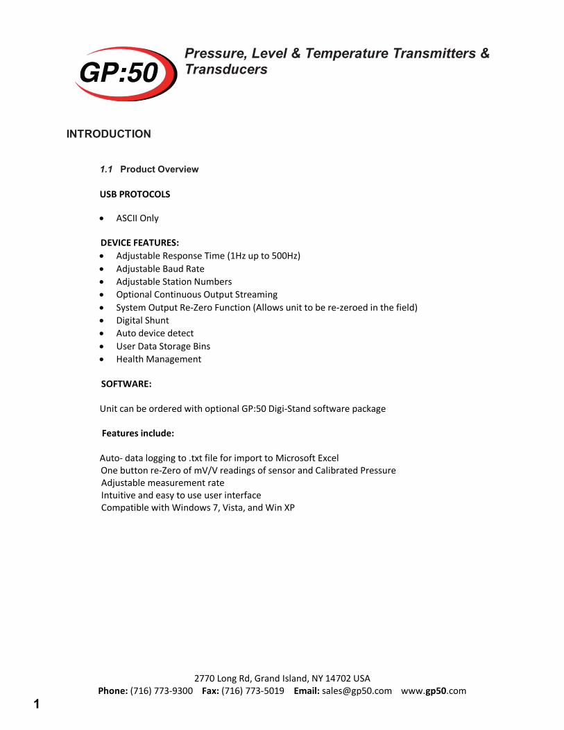
1.1 Product Overview
USB PROTOCOLS
• ASCII Only
DEVICE FEATURES: • Adjustable Response Time (1Hz up to 500Hz)• Adjustable Baud Rate• Adjustable Station Numbers• Optional Continuous Output Streaming• System Output Re-Zero Function (Allows unit to be re-zeroed in the field)• Digital Shunt• Auto device detect• User Data Storage Bins• Health Management
SOFTWARE:
Unit can be ordered with optional GP:50 Digi-Stand software package
Features include:
Auto- data logging to .txt file for import to Microsoft Excel One button re-Zero of mV/V readings of sensor and Calibrated Pressure Adjustable measurement rate Intuitive and easy to use user interface Compatible with Windows 7, Vista, and Win XP
1
Pressure, Level & Temperature Transmitters & Transducers
2770 Long Rd, Grand Island, NY 14702 USA Phone: (716) 773-9300 Fax: (716) 773-5019 Email: [email protected] www.gp50.com
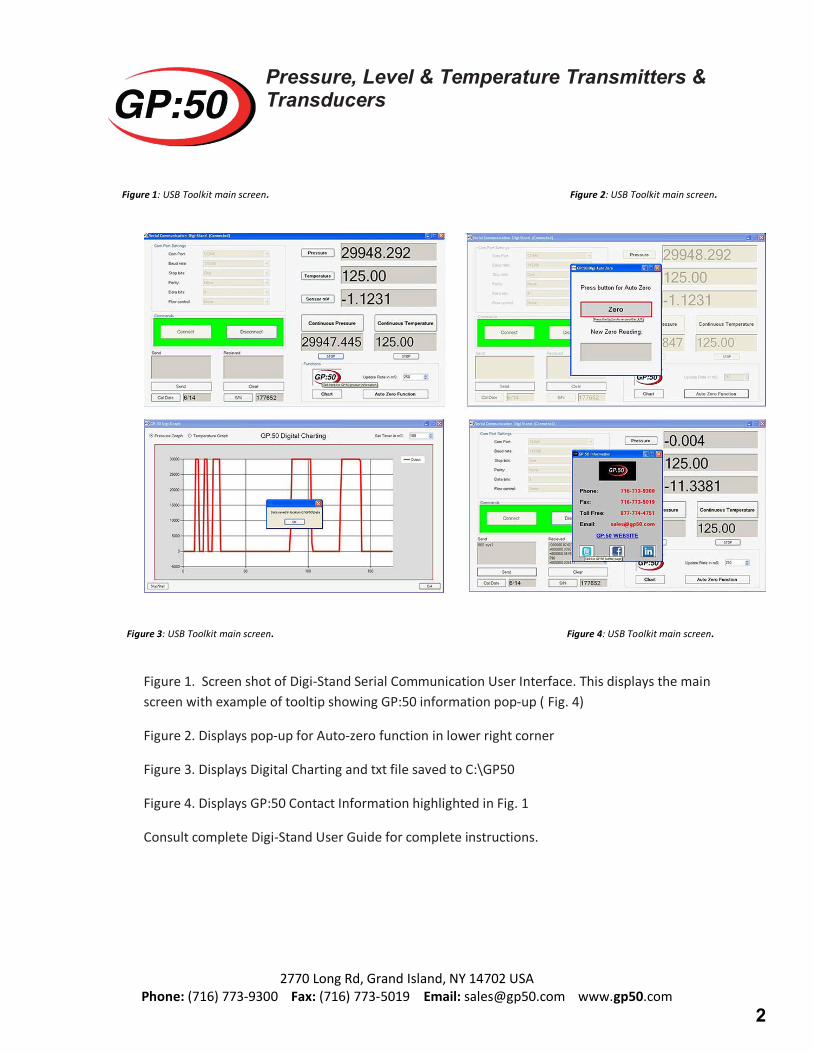
Figure 1: USB Toolkit main screen. Figure 2: USB Toolkit main screen.
Figure 3: USB Toolkit main screen. Figure 4: USB Toolkit main screen.
Figure 1. Screen shot of Digi-Stand Serial Communication User Interface. This displays the main screen with example of tooltip showing GP:50 information pop-up ( Fig. 4)
Figure 2. Displays pop-up for Auto-zero function in lower right corner
Figure 3. Displays Digital Charting and txt file saved to C:\GP50
Figure 4. Displays GP:50 Contact Information highlighted in Fig. 1
Consult complete Digi-Stand User Guide for complete instructions.
2
Pressure, Level & Temperature Transmitters & Transducers
2770 Long Rd, Grand Island, NY 14702 USA Phone: (716) 773-9300 Fax: (716) 773-5019 Email: [email protected] www.gp50.com
1.2 Warning Pressurized vessels and associated equipment are potentially dangerous. The product described in the guide should be operated only by personnel trained in the procedures that will assure safety to themselves, to others, to the equipment, and to the product. Specific warnings are noted as in specific installation/operation sections.
1.3 Unpacking and Inspection All models covered in this manual are carefully tested, inspected and packed. Upon receipt of the shipment thoroughly inspect the transducer. If you see any visible signs of obvious shipping damage, notify the freight company immediately.
1.4 Using this manual This manual is intended to help the end user install, maintain, and provide general service of GP:50 Model 611/612 USB digital output Pressure Transducer. The user should have an understanding of general instrumentation control. All aforementioned models are precision instruments and should be given the same care as any other precision instrument during installation and operation.
2. INSTALLATION
2.1 Mounting/Process Connection
Model 611/612 can be ordered with a number of optional pressure ports depending on pressure range. Consult factory for availability. Installation of the device shall be in accordance with industry standard pipe fitting requirements for this size. During installation or removal torque should only be applied at the wrench flats provided on the pressure port. As a general rule of thumb, the device shall be “wrench-tight” to avoid leakage from the process connection.
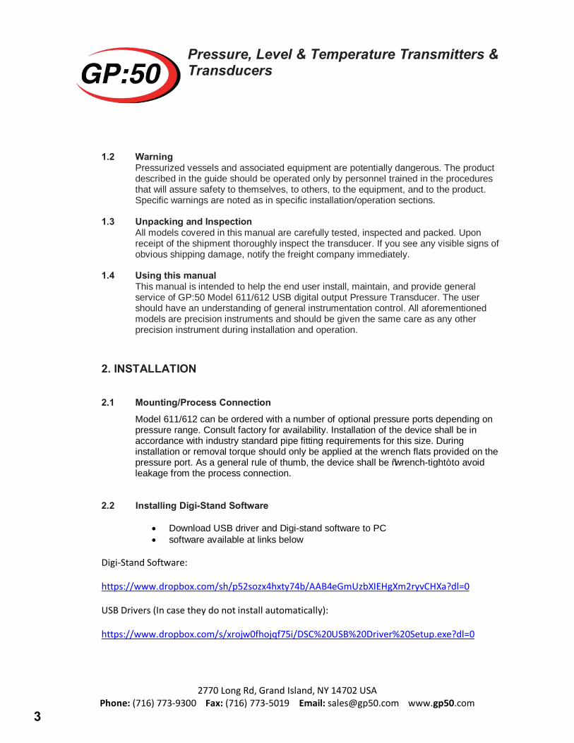
2.2 Installing Digi-Stand Software
• Download USB driver and Digi-stand software to PC• software available at links below
Digi-Stand Software:
https://www.dropbox.com/sh/p52sozx4hxty74b/AAB4eGmUzbXIEHgXm2ryvCHXa?dl=0
USB Drivers (In case they do not install automatically):
https://www.dropbox.com/s/xrojw0fhojqf75i/DSC%20USB%20Driver%20Setup.exe?dl=0
3
Pressure, Level & Temperature Transmitters & Transducers
2770 Long Rd, Grand Island, NY 14702 USA Phone: (716) 773-9300 Fax: (716) 773-5019 Email: [email protected] www.gp50.com
• Connect the USB unit to an open com port connection on your computer orlaptop
• Unzip the Digi-Stand application Zip file to a location on your C drive• Run the GP50 Digi-Stand application file, this will automatically install the
application to your computer• Open the Digi-Stand application and select the COM port value that is populated.• Click the Connect button, you should now be connected and have pressure data.
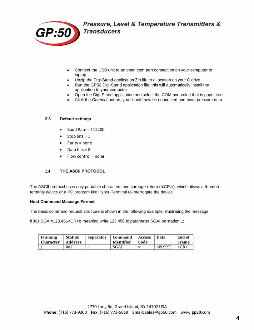
2.3 Default settings
• Baud Rate = 115200• Stop bits = 1• Parity = none• Data bits = 8• Flow control = none
2.4 THE ASCII PROTOCOL
The ASCII protocol uses only printable characters and carriage-return (‘<CR>’), which allows a “dumb” terminal device or a PC program like Hyper-Terminal to interrogate the device.
Host Command Message Format
The basic command request structure is shown in the following example, illustrating the message
“!001:SGAI=123.456<CR>”, meaning write 123.456 to parameter SGAI on station 1:
Framing Character
Station Address
Separator Command Identifier
Access Code
Data End of Frame ! 001 : SGAI = -99.9999 <CR>
4
Pressure, Level & Temperature Transmitters & Transducers
2770 Long Rd, Grand Island, NY 14702 USA Phone: (716) 773-9300 Fax: (716) 773-5019 Email: [email protected] www.gp50.com
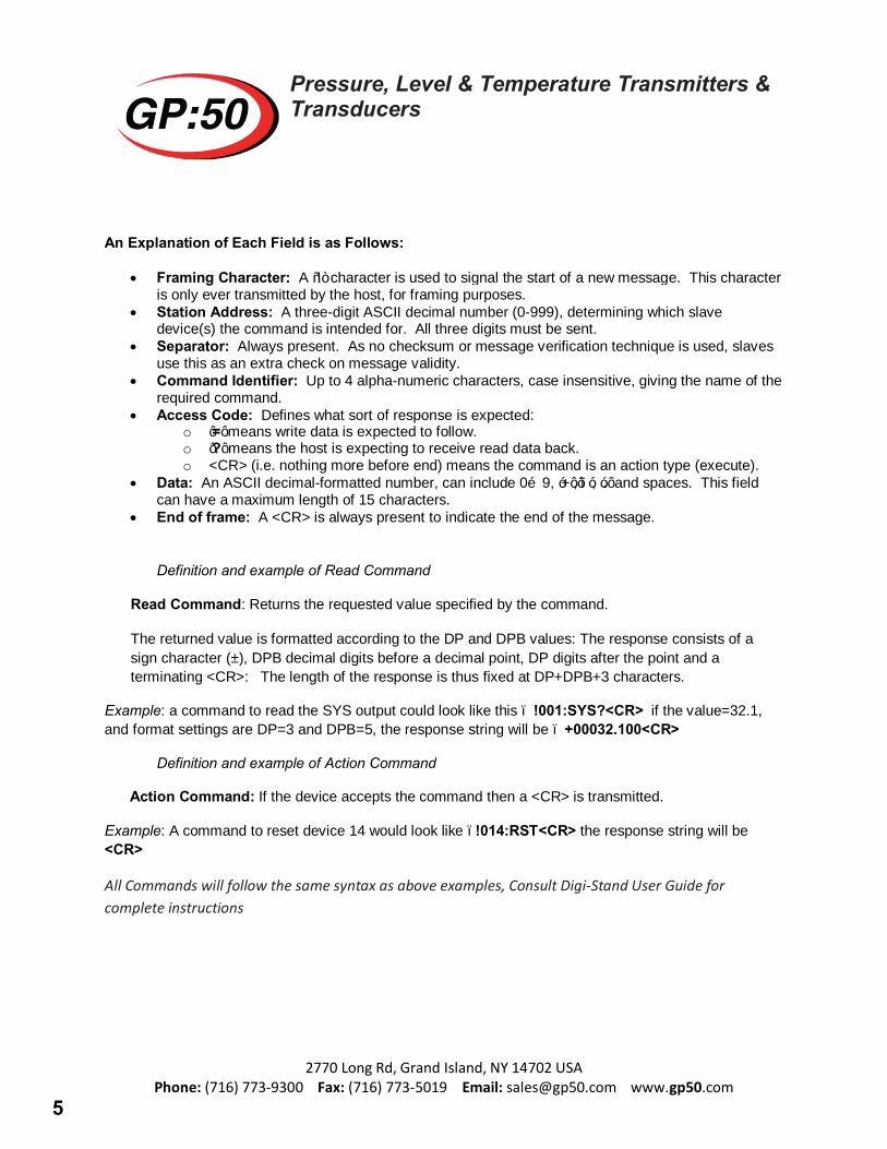
An Explanation of Each Field is as Follows:
• Framing Character: A “!” character is used to signal the start of a new message. This characteris only ever transmitted by the host, for framing purposes.
• Station Address: A three-digit ASCII decimal number (0-999), determining which slavedevice(s) the command is intended for. All three digits must be sent.
• Separator: Always present. As no checksum or message verification technique is used, slavesuse this as an extra check on message validity.
• Command Identifier: Up to 4 alpha-numeric characters, case insensitive, giving the name of therequired command.
• Access Code: Defines what sort of response is expected:o ’=’ means write data is expected to follow.o ’?’ means the host is expecting to receive read data back.o <CR> (i.e. nothing more before end) means the command is an action type (execute).
• Data: An ASCII decimal-formatted number, can include 0…9, ‘+’,’–‘, ‘.’ and spaces. This fieldcan have a maximum length of 15 characters.
• End of frame: A <CR> is always present to indicate the end of the message.
Definition and example of Read Command
Read Command: Returns the requested value specified by the command.
The returned value is formatted according to the DP and DPB values: The response consists of a sign character (±), DPB decimal digits before a decimal point, DP digits after the point and a terminating <CR>: The length of the response is thus fixed at DP+DPB+3 characters.
Example: a command to read the SYS output could look like this – !001:SYS?<CR> if the value=32.1, and format settings are DP=3 and DPB=5, the response string will be – +00032.100<CR>
Definition and example of Action Command
Action Command: If the device accepts the command then a <CR> is transmitted.
Example: A command to reset device 14 would look like –!014:RST<CR> the response string will be <CR>
All Commands will follow the same syntax as above examples, Consult Digi-Stand User Guide for complete instructions
5
Pressure, Level & Temperature Transmitters & Transducers
2770 Long Rd, Grand Island, NY 14702 USA Phone: (716) 773-9300 Fax: (716) 773-5019 Email: [email protected] www.gp50.com
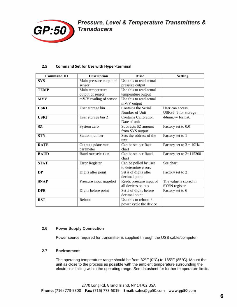
2.5 Command Set for Use with Hyper-terminal
Command ID Description Misc Setting SYS Main pressure output of
sensor Use this to read actual pressure output
TEMP Main temperature output of sensor
Use this to read actual temperature output
MVV mV/V reading of sensor Use this to read actual mV/V output
USR1 User storage bin 1 Contains the Serial Number of Unit
User can access USR3…9 for storage
USR2 User storage bin 2 Contains Calibration Date of unit
ddmm.yy format.
SZ System zero Subtracts SZ amount from SYS output
Factory set to 0.0
STN Station number Sets the address of the unit.
Factory set to 1
RATE Output update rate parameter
Can be set per Rate chart
Factory set to 3 = 10Hz
BAUD Baud rate selection Can be set per Baud chart
Factory set to 2=115200
STAT Error Register Can be polled by user to determine errors
See chart
DP Digits after point Set # of digits after decimal point
Factory set to 2
SNAP Pressure input snapshot Reads pressure input of all devices on bus
The value is stored in SYSN register
DPB Digits before point Set # of digits before decimal point
Factory set to 6
RST Reboot Use this to reboot / power cycle the device
2.6 Power Supply Connection
Power source required for transmitter is supplied through the USB cable/computer.
2.7 Environment
The operating temperature range should be from 32°F (0°C) to 185°F (85°C). Mount the unit as close to the process as possible with the ambient temperature surrounding the electronics falling within the operating range. See datasheet for further temperature limits.
6
Pressure, Level & Temperature Transmitters & Transducers
2770 Long Rd, Grand Island, NY 14702 USA Phone: (716) 773-9300 Fax: (716) 773-5019 Email: [email protected] www.gp50.com
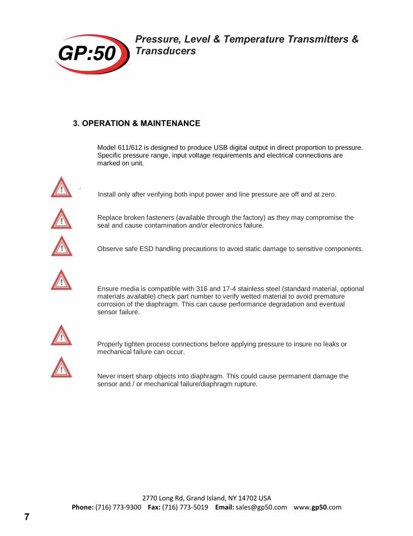
3. OPERATION & MAINTENANCE
Model 611/612 is designed to produce USB digital output in direct proportion to pressure. Specific pressure range, input voltage requirements and electrical connections are marked on unit.
. Install only after verifying both input power and line pressure are off and at zero.
Replace broken fasteners (available through the factory) as they may compromise the seal and cause contamination and/or electronics failure.
Observe safe ESD handling precautions to avoid static damage to sensitive components.
Ensure media is compatible with 316 and 17-4 stainless steel (standard material, optional materials available) check part number to verify wetted material to avoid premature corrosion of the diaphragm. This can cause performance degradation and eventual sensor failure.
Properly tighten process connections before applying pressure to insure no leaks or mechanical failure can occur.
Never insert sharp objects into diaphragm. This could cause permanent damage the sensor and / or mechanical failure/diaphragm rupture.
7
Pressure, Level & Temperature Transmitters & Transducers
2770 Long Rd, Grand Island, NY 14702 USA Phone: (716) 773-9300 Fax: (716) 773-5019 Email: [email protected] www.gp50.com
4. TROUBLESHOOTING & RETURN INFORMATION
No output
- Verify baud rate is correct- Verify station number is correct- Verify Com Port value is correct- Verify power supply voltage meets transducer requirements- Verify pressure if being applied- Verify output load is not shorted
Erratic output or zero drift
- Verify pressure applied is constant- Verify power supply remains within specifications- Inspect USB cable for discontinuity or damage- Verify output with a multi-meter- Check insulation resistance between amplifier and transducer case
Slow Response
- Verify pressure port is not clogged
If the problem persists, please call the factory as indicated below for assistance. Please have the following information ready:
• Serial number• Model number• Which action caused device failure
Contact: [email protected]
Repairs should only be done by GP:50. Repairs done by customer will void any warranties and may cause permanent damage to unit. Repairs done by customer on Intrinsically Safe units will void the approvals and are a potential explosion hazard.
Returned products that have been exposed to hazardous substances should be cleaned prior to return and should include the Material Safety Data Sheet for all substances.
8
Pressure, Level & Temperature Transmitters & Transducers
2770 Long Rd, Grand Island, NY 14702 USA Phone: (716) 773-9300 Fax: (716) 773-5019 Email: [email protected] www.gp50.com
5. WARRANTY
GP:50 warrants its products to the original customer/purchaser against defects in material and workmanship for a period of one (1) year from the date of delivery by GP:50, as shown in its shipping documents, subject to the following terms and conditions:
Without charge GP:50 will repair or replace products found to be defective in materials or workmanship within the warranty period provided that:
1. The product has not been subjected to abuse, neglect, accident, incorrect wiring (notprovided by GP:50), improper installation or servicing, or use in violation of instructionsfurnished by GP:50.
2. As to any prior defect in materials or workmanship covered by this warranty, the product hasnot been repaired or altered by anyone except GP:50 or its authorized service agencies.
3. The serial number has not been removed, defaced or otherwise changed.
4. Examination discloses, in the judgment of GP:50, a defect in materials or workmanship whichdeveloped under normal installation, use and service.
5. GP:50 is notified in advance of, and approves, the return by issuing a Return MaterialAuthorization Number; and the products are returned to GP:50 transportation prepaid.Products returned without an RMA number will not be accepted and be returned to sender atsender’s expense.
THIS WARRANTY IS THE ONLY WARRANTY AND IS IN LIEU OF ANY OTHER WARRANTY EXPRESSED OR IMPLIED, INCLUDING ANY WARRANTY OR MERCHANTABILITY OR FITNESS. NO REPRESENTATIVE OR PERSONS ARE AUTHORIZED TO GIVE ANY OTHER WARRANTY OR TO ASSUME FOR GP:50 ANY OTHER LIABILITY IN CONNECTION WITH THE SALE OF ITS PRODUCTS. GP:50 DOES NOT ASSUME THE COSTS OF REMOVAL AND/OR INSTALLATION OF THE PRODUCT OR ANY OTHER WORKMANSHIP, OR WILL GP:50 BE LIABLE FOR ANY CONSEQUENTIAL DAMAGES RESULTING FROM THE USE OR INSALLATION OF ITS PRODUCT.
Contact our website http://www. GP50.com for a copy of our repair policy or call our repair dept. Copyright© 2008 GP:50
9