Embed Size (px)
Citation preview
Process ManagementTM
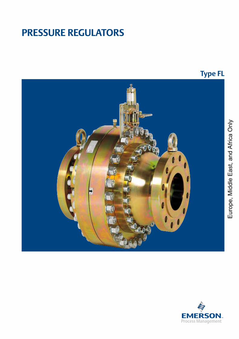
Type FL
PRESSURE REGULATORS
Eur
ope,
Mid
dle
Eas
t, an
d A
frica
Onl
y
2
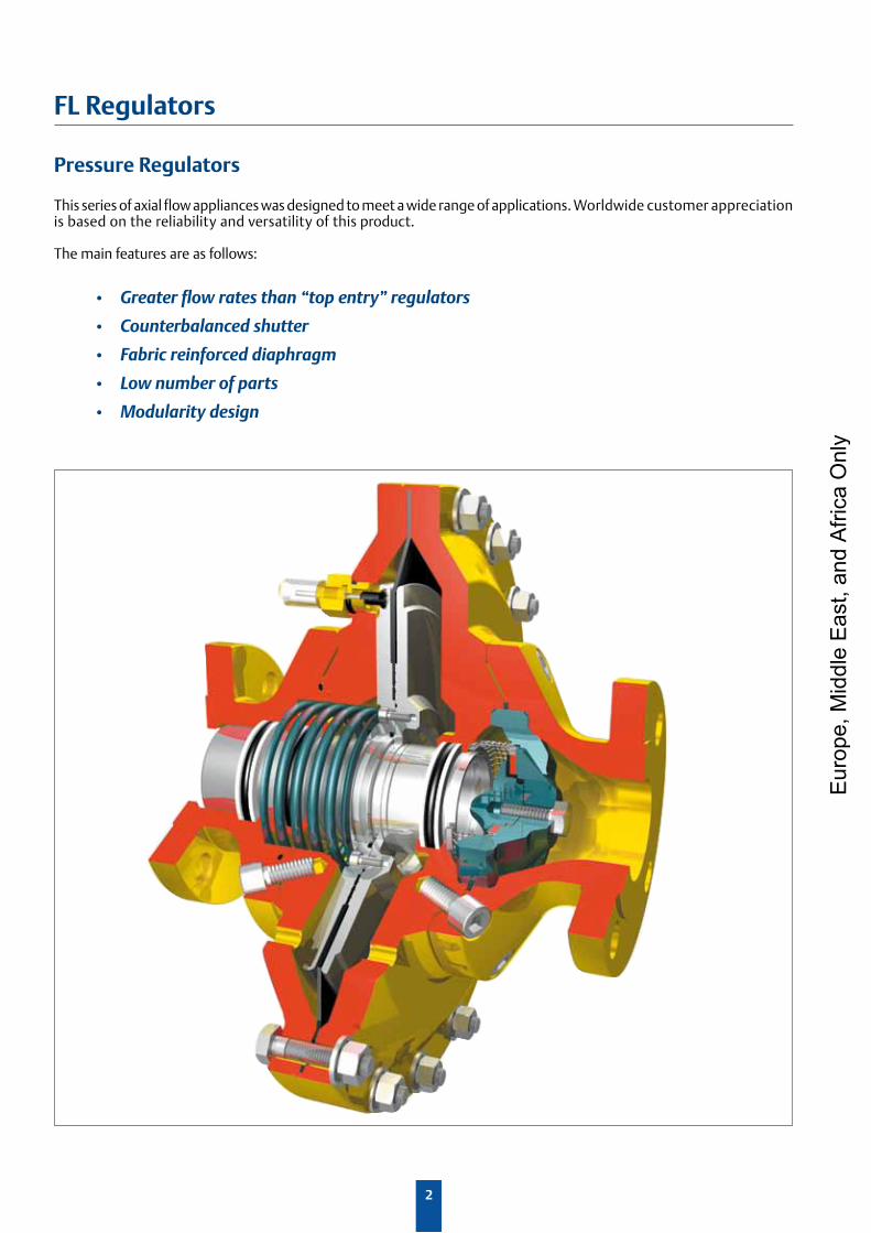
FL Regulators
This series of axial flow appliances was designed to meet a wide range of applications. Worldwide customer appreciation is based on the reliability and versatility of this product.
The main features are as follows:
• Greaterflowratesthan“topentry”regulators
• Counterbalancedshutter
• Fabricreinforceddiaphragm
• Lownumberofparts
• Modularitydesign
Pressure Regulators
Eur
ope,
Mid
dle
Eas
t, an
d A
frica
Onl
y
3
FL Regulators
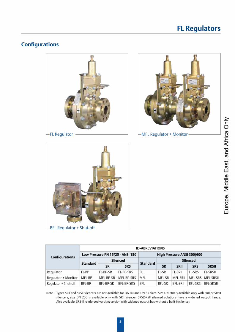
Configurations
FL Regulator MFL Regulator + Monitor
BFL Regulator + Shut-off
Note : Types SRII and SRSII silencers are not available for DN 40 and DN 65 sizes. Size DN 200 is available only with SRII or SRSII silencers, size DN 250 is available only with SRII silencer. SRS/SRSII silenced solutions have a widened output flange. Also available: SRS-R reinforced version; version with widened output but without a built-in silencer.
Configurations
ID-ABREVIATIONS
Low Pressure PN 16/25 - ANSI 150 High Pressure ANSI 300/600
StandardSilenced
StandardSilenced
SR SRS SR SRII SRS SRSII
Regulator FL-BP FL-BP-SR FL-BP-SRS FL FL-SR FL-SRII FL-SRS FL-SRSII
Regulator + Monitor MFL-BP MFL-BP-SR MFL-BP-SRS MFL MFL-SR MFL-SRII MFL-SRS MFL-SRSII
Regulator + Shut-off BFL-BP BFL-BP-SR BFL-BP-SRS BFL BFL-SR BFL-SRII BFL-SRS BFL-SRSII
Eur
ope,
Mid
dle
Eas
t, an
d A
frica
Onl
y
4
FL Regulators
Operation
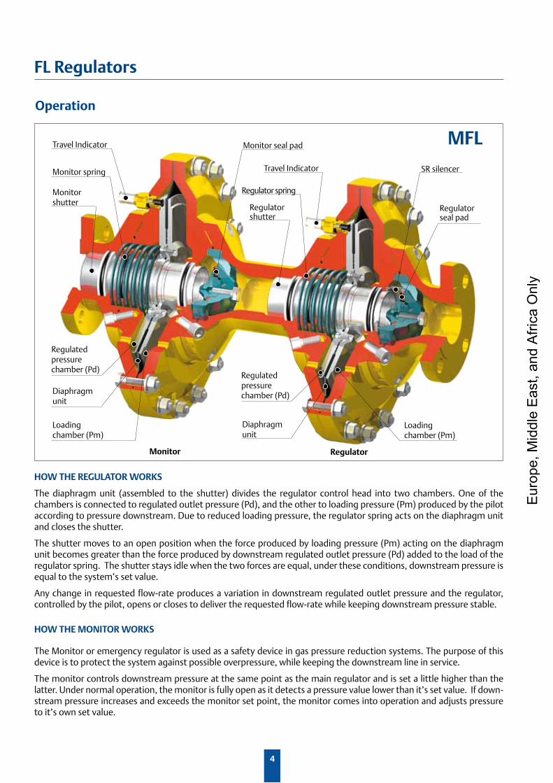
Travel Indicator
Monitor spring
Monitorshutter
Regulatedpressurechamber (Pd)
Diaphragmunit
Loadingchamber (Pm)
Monitor seal pad
Travel Indicator
Regulator spring
Regulatorshutter
Regulatedpressurechamber (Pd)
Diaphragmunit
Loadingchamber (Pm)
SR silencer
Regulatorseal pad
Monitor Regulator
HOW THE REGULATOR WORKS
The diaphragm unit (assembled to the shutter) divides the regulator control head into two chambers. One of the chambers is connected to regulated outlet pressure (Pd), and the other to loading pressure (Pm) produced by the pilot according to pressure downstream. Due to reduced loading pressure, the regulator spring acts on the diaphragm unit and closes the shutter.
The shutter moves to an open position when the force produced by loading pressure (Pm) acting on the diaphragm unit becomes greater than the force produced by downstream regulated outlet pressure (Pd) added to the load of the regulator spring. The shutter stays idle when the two forces are equal, under these conditions, downstream pressure is equal to the system’s set value.
Any change in requested flow-rate produces a variation in downstream regulated outlet pressure and the regulator, controlled by the pilot, opens or closes to deliver the requested flow-rate while keeping downstream pressure stable.
HOW THE MONITOR WORKS
The Monitor or emergency regulator is used as a safety device in gas pressure reduction systems. The purpose of this device is to protect the system against possible overpressure, while keeping the downstream line in service.
The monitor controls downstream pressure at the same point as the main regulator and is set a little higher than the latter. Under normal operation, the monitor is fully open as it detects a pressure value lower than it’s set value. If down-stream pressure increases and exceeds the monitor set point, the monitor comes into operation and adjusts pressure to it’s own set value.
MFL
Eur
ope,
Mid
dle
Eas
t, an
d A
frica
Onl
y
5
FL Regulators
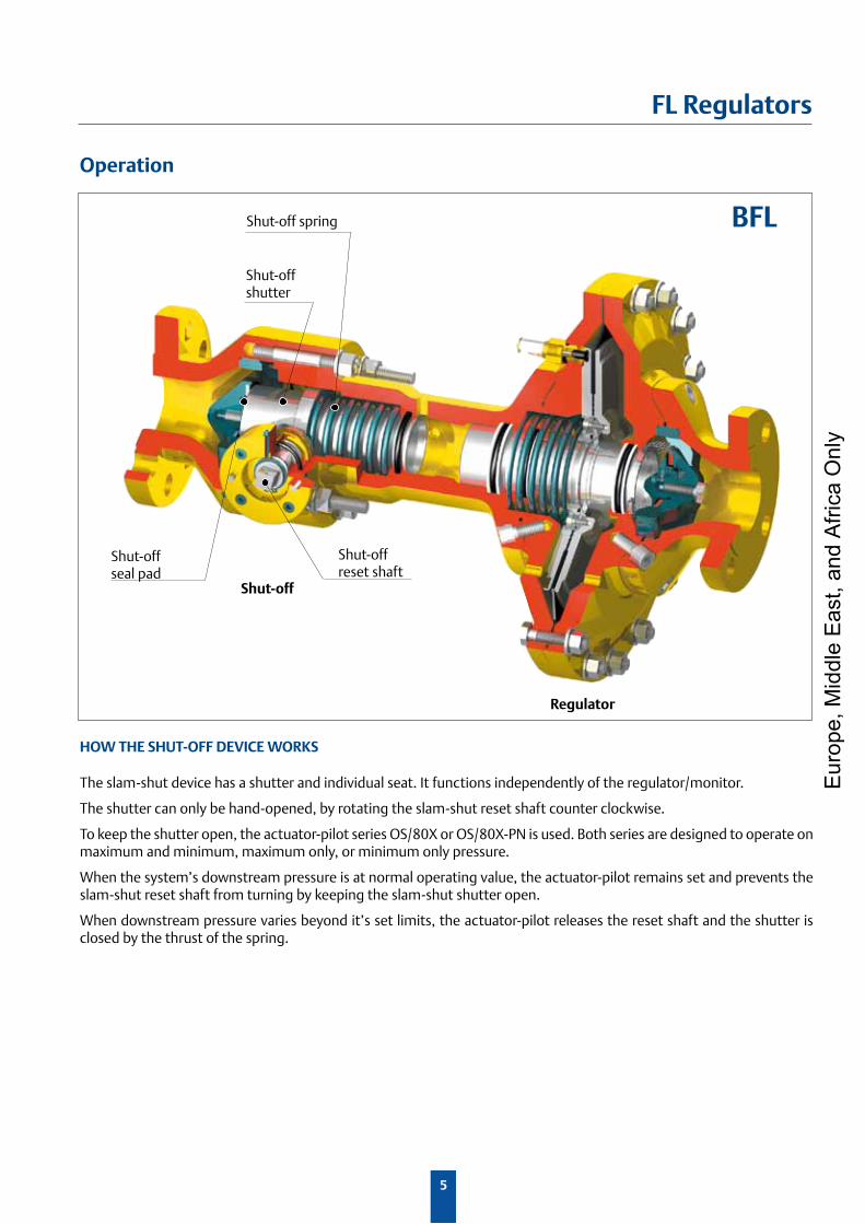
HOW THE SHUT-OFF DEVICE WORKS
The slam-shut device has a shutter and individual seat. It functions independently of the regulator/monitor.
The shutter can only be hand-opened, by rotating the slam-shut reset shaft counter clockwise.
To keep the shutter open, the actuator-pilot series OS/80X or OS/80X-PN is used. Both series are designed to operate on maximum and minimum, maximum only, or minimum only pressure.
When the system’s downstream pressure is at normal operating value, the actuator-pilot remains set and prevents the slam-shut reset shaft from turning by keeping the slam-shut shutter open.
When downstream pressure varies beyond it’s set limits, the actuator-pilot releases the reset shaft and the shutter is closed by the thrust of the spring.
Shut-off spring
Shut-offshutter
Shut-offseal pad
Shut-offreset shaft
Regulator
Shut-off
Operation
BFL
Eur
ope,
Mid
dle
Eas
t, an
d A
frica
Onl
y
6
FL Regulators
Features
Technical Features
Materials Flanges and covers: Carbon SteelDiaphragms: Fabric NBR+PVC/Nitrile rubberPads: NBR Nitrile rubber
Allowable pressure PS : up to 100 barInlet pressure range bpu : 1 to 100 barSet range Wd : 0.5 to 80 bar Min. operating differential pres. ∆pmin : 0.5 bar
Flange rating PN 16/25 - ANSI 150
Flange rating ANSI 300/600
TemperatureStandard version Working: -10 °C +60 °C
Low temperature versionWorking: -20 °C +60 °C
Shut-off device
Accuracy class AG : up to ± 1% Response time ta : ≤1s
Identical Inlet and outlet : DN 25 - 40 - 50 - 65 - 80 - 100 - 150* - 200* - 250*Different Inlet and outlet : DN 25x100 - 40x150 - 50x150 - 65x200 - 80x250 - 100x250 150x300* - 200x400*(*) These sizes are not available in MFL and BFL configurations DN 200 and DN 250 BP versions are not available
Flanged connections
Applications FL series regulators are used in reduction, distribution and conveying stations of suitably filtered natural gas. They can also be used for air, propane, butane, LPG, city gas, nitrogen, carbon dioxide and hydrogen.
Allowable pressure PS : up to 25 barInlet pressure range bpu : 0.2 to 25 barSet range Wd : 0.01 to 8 bar Min. operating differential pres. ∆pmin : 0.2 bar
Accuracy class AC : up to ± 1% Lock-up pressure class SG : up to + 5%Class of lock-up pressure zone SZ : up to 5%
Functional Features
Eur
ope,
Mid
dle
Eas
t, an
d A
frica
Onl
y
7
FL Regulators
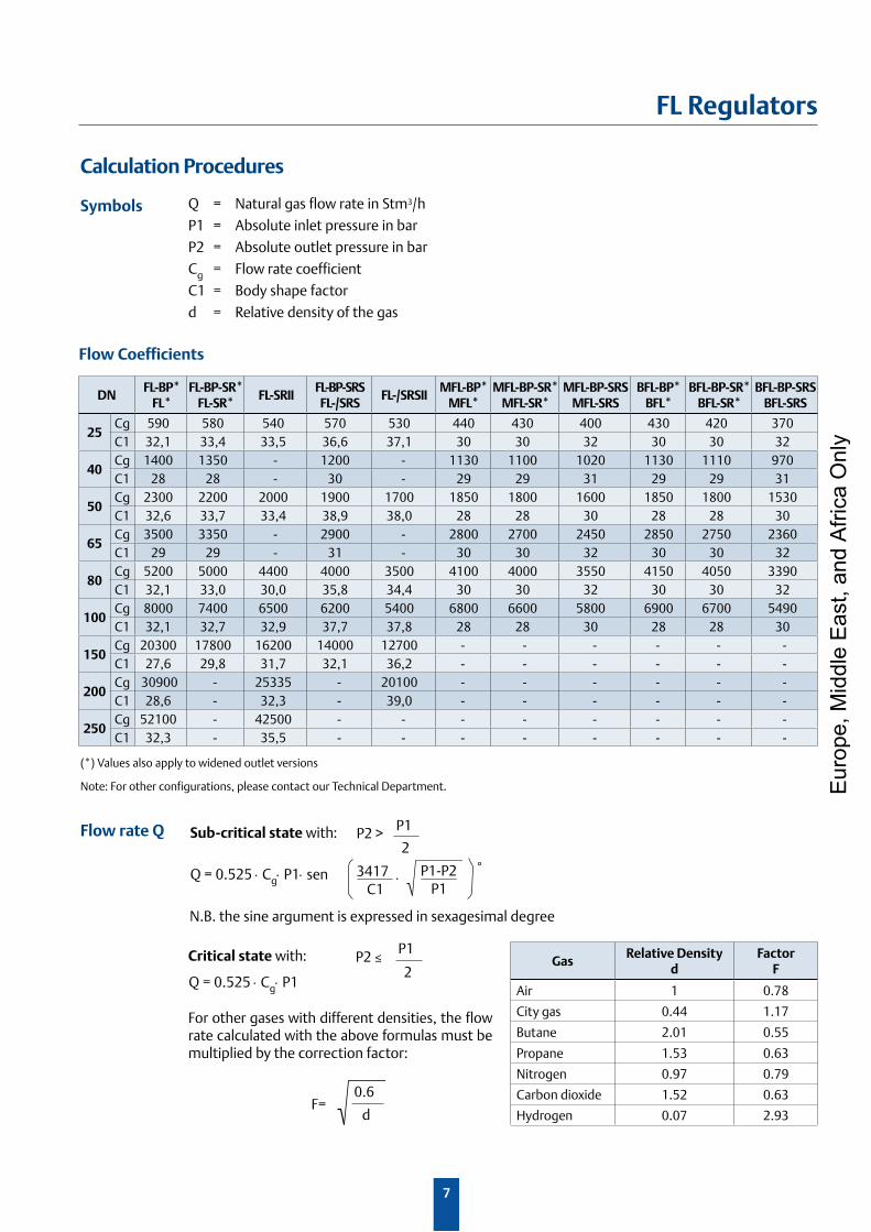
Calculation Procedures
Symbols
For other gases with different densities, the flow rate calculated with the above formulas must be multiplied by the correction factor:
Sub-critical state with: P1
2P2 >
Q = Natural gas flow rate in Stm3/h
P1 = Absolute inlet pressure in bar
P2 = Absolute outlet pressure in bar
Cg = Flow rate coefficient
C1 = Body shape factor
d = Relative density of the gas
0.6
dF=
Flow rate Q
N.B. the sine argument is expressed in sexagesimal degree
Critical state with: P1
2P2≤
Q = 0.525 ⋅ Cg⋅ P1
Q = 0.525 ⋅ Cg⋅ P1⋅ sen P1-P2P1
°3417C1
⋅
(*) Values also apply to widened outlet versions
Note: For other configurations, please contact our Technical Department.
GasRelative Density
dFactor
F
Air 1 0.78
City gas 0.44 1.17
Butane 2.01 0.55
Propane 1.53 0.63
Nitrogen 0.97 0.79
Carbon dioxide 1.52 0.63
Hydrogen 0.07 2.93
Flow Coefficients
DNFL-BP*
FL*FL-BP-SR*
FL-SR*FL-SRII
FL-BP-SRSFL-/SRS
FL-/SRSIIMFL-BP*
MFL*MFL-BP-SR*
MFL-SR*MFL-BP-SRS
MFL-SRSBFL-BP*
BFL*BFL-BP-SR*
BFL-SR*BFL-BP-SRS
BFL-SRS
25Cg 590 580 540 570 530 440 430 400 430 420 370C1 32,1 33,4 33,5 36,6 37,1 30 30 32 30 30 32
40Cg 1400 1350 - 1200 - 1130 1100 1020 1130 1110 970C1 28 28 - 30 - 29 29 31 29 29 31
50Cg 2300 2200 2000 1900 1700 1850 1800 1600 1850 1800 1530C1 32,6 33,7 33,4 38,9 38,0 28 28 30 28 28 30
65Cg 3500 3350 - 2900 - 2800 2700 2450 2850 2750 2360C1 29 29 - 31 - 30 30 32 30 30 32
80Cg 5200 5000 4400 4000 3500 4100 4000 3550 4150 4050 3390C1 32,1 33,0 30,0 35,8 34,4 30 30 32 30 30 32
100Cg 8000 7400 6500 6200 5400 6800 6600 5800 6900 6700 5490C1 32,1 32,7 32,9 37,7 37,8 28 28 30 28 28 30
150Cg 20300 17800 16200 14000 12700 - - - - - -C1 27,6 29,8 31,7 32,1 36,2 - - - - - -
200Cg 30900 - 25335 - 20100 - - - - - -C1 28,6 - 32,3 - 39,0 - - - - - -
250Cg 52100 - 42500 - - - - - - - -C1 32,3 - 35,5 - - - - - - - -
Eur
ope,
Mid
dle
Eas
t, an
d A
frica
Onl
y
8
FL Regulators
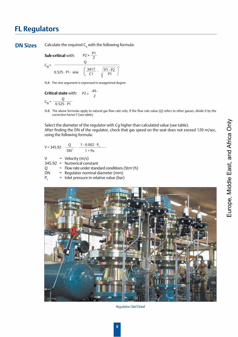
Calculate the required Cg with the following formula:
N.B. The above formulas apply to natural gas flow rate only. If the flow rate value (Q) refers to other gasses, divide it by the correction factor F (see table).
V = Velocity (m/s)345.92 = Numerical constantQ = Flow rate under standard conditions (Stm3/h)DN = Regulator nominal diameter (mm)Pu = Inlet pressure in relative value (bar)
DN Sizes
Cg =Q
0.525 ⋅ P1 ⋅ sineP1 - P2
P1
°3417C1
⋅
Sub-critical with:P12
P2 >
Q0.525 ⋅ P1
Cg =
N.B. The sine argument is expressed in sexagesimal degree
Critical state with: P12
P2≤
Select the diameter of the regulator with Cg higher than calculated value (see table).After finding the DN of the regulator, check that gas speed on the seat does not exceed 120 m/sec, using the following formula:
V = 345.92 ⋅ Q
DN2⋅
1 - 0.002 ⋅ Pu
1 + Pu
Regulation Skid Detail
Eur
ope,
Mid
dle
Eas
t, an
d A
frica
Onl
y
9
FL Regulators
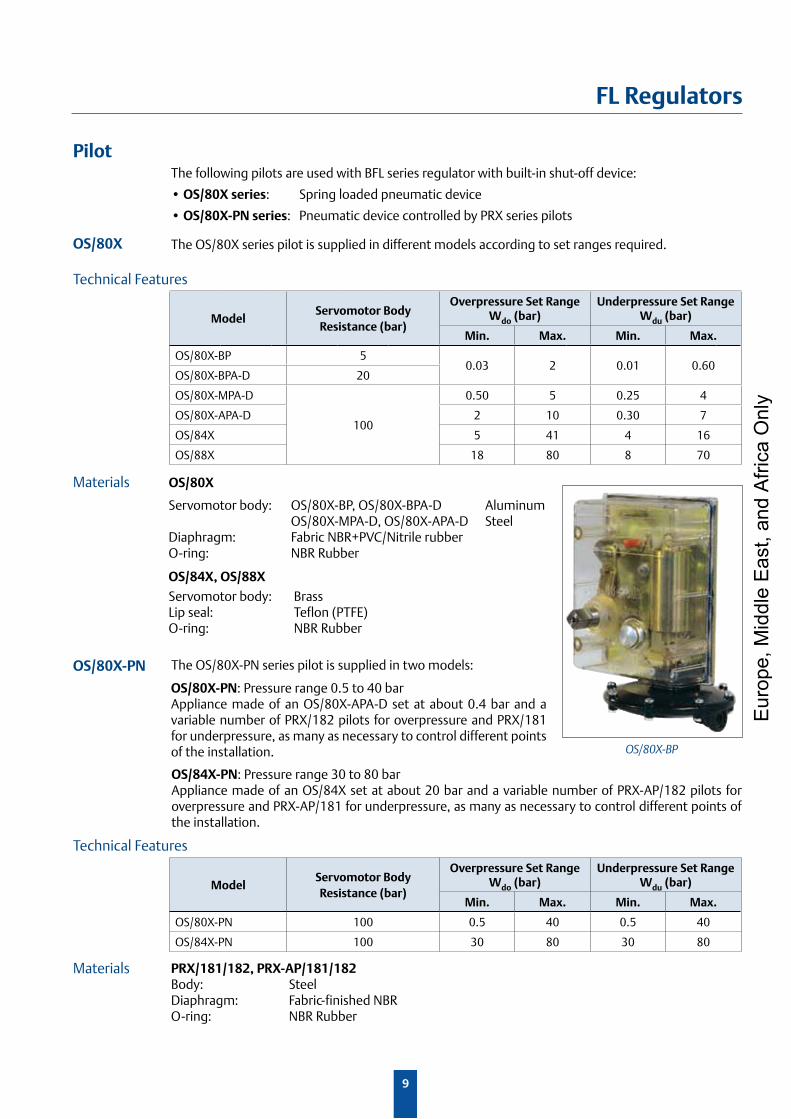
Servomotor body: OS/80X-BP, OS/80X-BPA-D Aluminum OS/80X-MPA-D, OS/80X-APA-D SteelDiaphragm: Fabric NBR+PVC/Nitrile rubberO-ring: NBR Rubber
OS/84X, OS/88X
Servomotor body: BrassLip seal: Teflon (PTFE)O-ring: NBR Rubber
PilotThe following pilots are used with BFL series regulator with built-in shut-off device:
•OS/80X series: Spring loaded pneumatic device
•OS/80X-PN series: Pneumatic device controlled by PRX series pilots
OS/80X The OS/80X series pilot is supplied in different models according to set ranges required.
PRX/181/182, PRX-AP/181/182Body: SteelDiaphragm: Fabric-finished NBRO-ring: NBR Rubber
Technical Features
Materials OS/80X
Technical Features
Materials
OS/84X-PN: Pressure range 30 to 80 barAppliance made of an OS/84X set at about 20 bar and a variable number of PRX-AP/182 pilots for overpressure and PRX-AP/181 for underpressure, as many as necessary to control different points of the installation.
OS/80X-PN: Pressure range 0.5 to 40 barAppliance made of an OS/80X-APA-D set at about 0.4 bar and a variable number of PRX/182 pilots for overpressure and PRX/181 for underpressure, as many as necessary to control different points of the installation.
The OS/80X-PN series pilot is supplied in two models:OS/80X-PN
OS/80X-BP
ModelServomotor Body Resistance (bar)
Overpressure Set Range Wdo (bar)
Underpressure Set Range Wdu (bar)
Min. Max. Min. Max.
OS/80X-PN 100 0.5 40 0.5 40
OS/84X-PN 100 30 80 30 80
ModelServomotor Body Resistance (bar)
Overpressure Set Range Wdo (bar)
Underpressure Set Range Wdu (bar)
Min. Max. Min. Max.
OS/80X-BP 50.03 2 0.01 0.60
OS/80X-BPA-D 20
OS/80X-MPA-D
100
0.50 5 0.25 4
OS/80X-APA-D 2 10 0.30 7
OS/84X 5 41 4 16
OS/88X 18 80 8 70
Eur
ope,
Mid
dle
Eas
t, an
d A
frica
Onl
y
10
FL Regulators
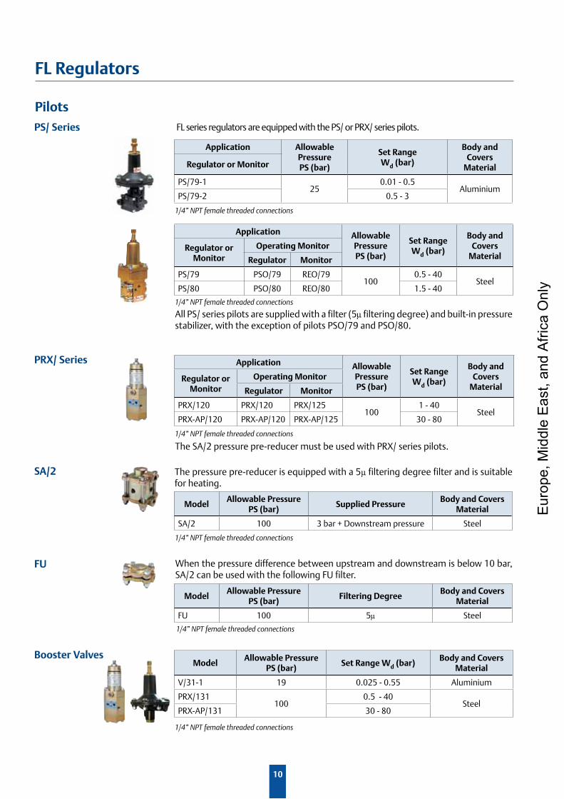
PilotsFL series regulators are equipped with the PS/ or PRX/ series pilots.PS/ Series
PRX/ Series
SA/2
FU
Booster Valves
1/4” NPT female threaded connections
1/4” NPT female threaded connections
All PS/ series pilots are supplied with a filter (5µ filtering degree) and built-in pressure stabilizer, with the exception of pilots PSO/79 and PSO/80.
1/4” NPT female threaded connections
The SA/2 pressure pre-reducer must be used with PRX/ series pilots.
The pressure pre-reducer is equipped with a 5µ filtering degree filter and is suitable for heating.
1/4” NPT female threaded connections
When the pressure difference between upstream and downstream is below 10 bar, SA/2 can be used with the following FU filter.
1/4” NPT female threaded connections
1/4” NPT female threaded connections
Application Allowable PressurePS (bar)
Set RangeWd (bar)
Body and Covers
MaterialRegulator or Monitor
PS/79-125
0.01 - 0.5Aluminium
PS/79-2 0.5 - 3
Application Allowable PressurePS (bar)
Set RangeWd (bar)
Body and Covers
MaterialRegulator or
MonitorOperating Monitor
Regulator Monitor
PS/79 PSO/79 REO/79100
0.5 - 40Steel
PS/80 PSO/80 REO/80 1.5 - 40
Application Allowable PressurePS (bar)
Set RangeWd (bar)
Body and Covers
MaterialRegulator or
MonitorOperating Monitor
Regulator Monitor
PRX/120 PRX/120 PRX/125100
1 - 40Steel
PRX-AP/120 PRX-AP/120 PRX-AP/125 30 - 80
ModelAllowable Pressure
PS (bar)Supplied Pressure
Body and Covers Material
SA/2 100 3 bar + Downstream pressure Steel
ModelAllowable Pressure
PS (bar)Filtering Degree
Body and Covers Material
FU 100 5µ Steel
ModelAllowable Pressure
PS (bar)Set Range Wd (bar)
Body and Covers Material
V/31-1 19 0.025 - 0.55 Aluminium
PRX/131100
0.5 - 40Steel
PRX-AP/131 30 - 80
Eur
ope,
Mid
dle
Eas
t, an
d A
frica
Onl
y
11
FL Regulators
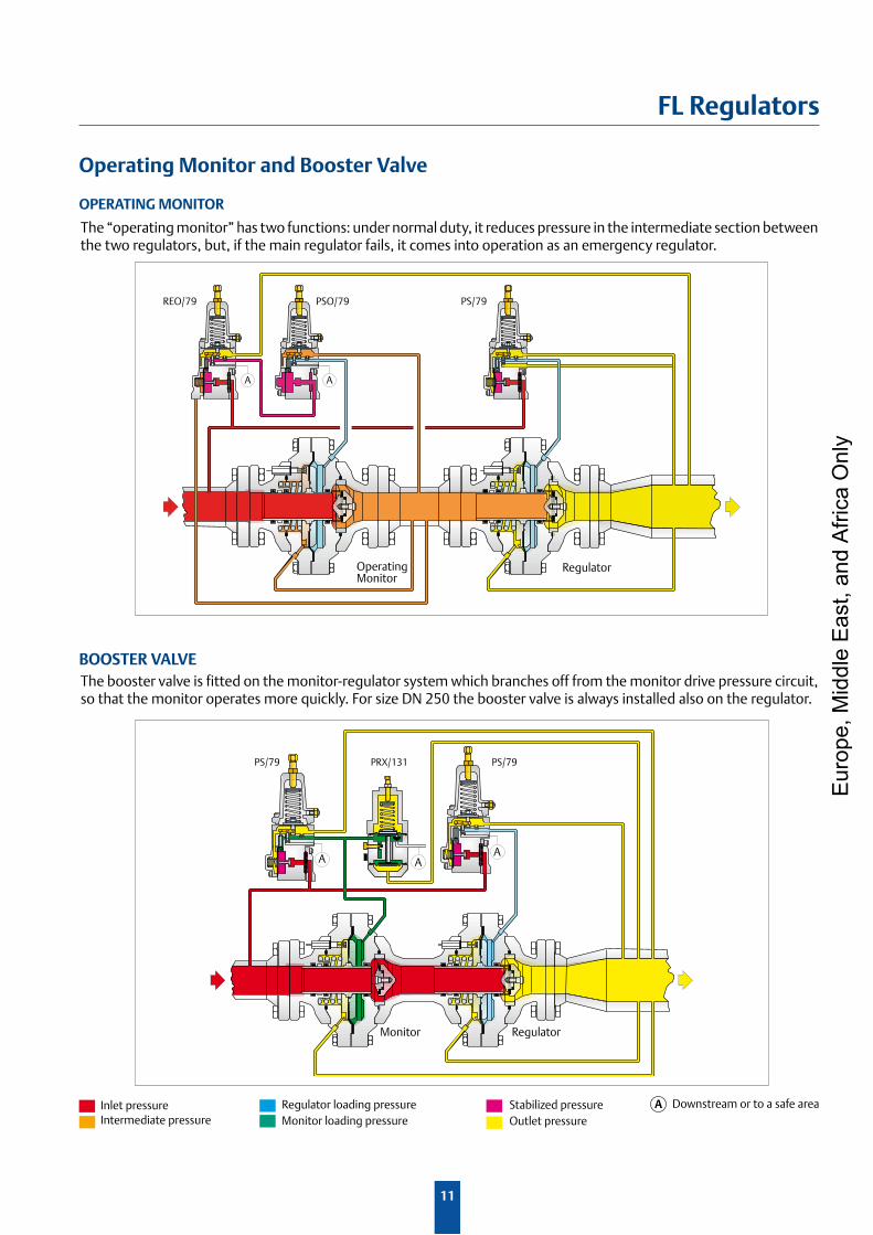
Operating Monitor and Booster Valve
The “operating monitor” has two functions: under normal duty, it reduces pressure in the intermediate section between the two regulators, but, if the main regulator fails, it comes into operation as an emergency regulator.
The booster valve is fitted on the monitor-regulator system which branches off from the monitor drive pressure circuit, so that the monitor operates more quickly. For size DN 250 the booster valve is always installed also on the regulator.
OPERATING MONITOR
BOOSTER VALVE
PS/79
AA
PSO/79REO/79
Operating Monitor
Regulator
AAA
PS/79 PS/79PRX/131
Monitor Regulator
Inlet pressureIntermediate pressure
Stabilized pressureOutlet pressure
Regulator loading pressure Monitor loading pressure
A Downstream or to a safe area
Eur
ope,
Mid
dle
Eas
t, an
d A
frica
Onl
y
12
FL Regulators
V≥ 200 m/s
V≤ 80 m/s
V=120 m/s
30
25
35
20
15
10
5
70 75 80 85 90 95 100 105 110 115 120
Built-in multi-path or split-flow silencer
Noise of non silenced regulator dB (A)
Noi
se re
duct
ion
dB (A
)
120
100
80
60
40
20
0
FL FL SR FL SR+SRS FL SRII FL SRII+SRS
0 20000 40000 60000 80000 100000 120000
Sound Performance Level
Noi
se d
B (A
)
Flow rate (Stm3/h)
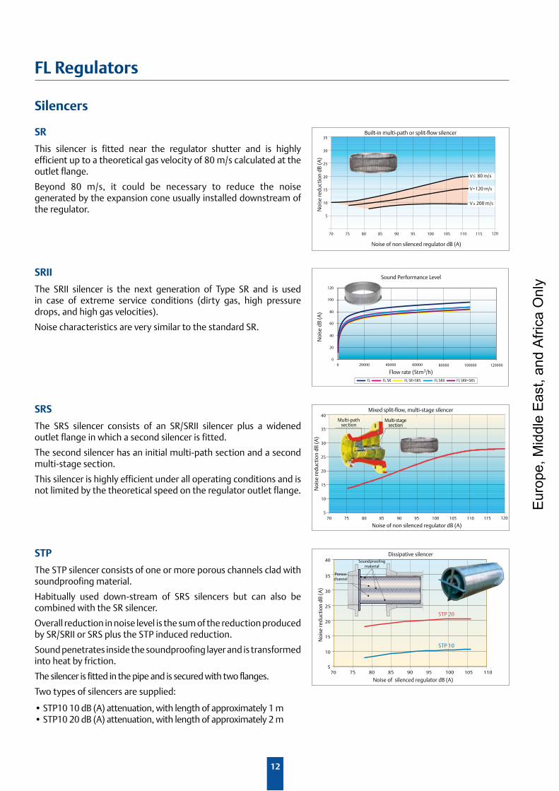
Silencers
STP
The STP silencer consists of one or more porous channels clad with soundproofing material.
Habitually used down-stream of SRS silencers but can also be combined with the SR silencer.
Overall reduction in noise level is the sum of the reduction produced by SR/SRII or SRS plus the STP induced reduction.
Sound penetrates inside the soundproofing layer and is transformed into heat by friction.
The silencer is fitted in the pipe and is secured with two flanges.
Two types of silencers are supplied:
•STP1010dB(A)attenuation,withlengthofapproximately1m•STP1020dB(A)attenuation,withlengthofapproximately2m
SRS
The SRS silencer consists of an SR/SRII silencer plus a widened outlet flange in which a second silencer is fitted.
The second silencer has an initial multi-path section and a second multi-stage section.
This silencer is highly efficient under all operating conditions and is not limited by the theoretical speed on the regulator outlet flange.
SRII
The SRII silencer is the next generation of Type SR and is used in case of extreme service conditions (dirty gas, high pressure drops, and high gas velocities).
Noise characteristics are very similar to the standard SR.
SR
This silencer is fitted near the regulator shutter and is highly efficient up to a theoretical gas velocity of 80 m/s calculated at the outlet flange.
Beyond 80 m/s, it could be necessary to reduce the noise generated by the expansion cone usually installed downstream of the regulator.
30
25
35
20
15
10
570 75 80 85 90 95 100 105 110 115 120
40
Noise of non silenced regulator dB (A)
Noi
se re
duct
ion
dB (A
)
Mixed split-flow, multi-stage silencer
Multi-pathsection
Multi-stagesection
STP 10
STP 20
30
25
35
20
15
10
570 75 80 85 90 95 100 105 110
40
Noise of silenced regulator dB (A)
Noi
se re
duct
ion
dB (A
)
Dissipative silencerSoundproofing
material
Porouschannel
Eur
ope,
Mid
dle
Eas
t, an
d A
frica
Onl
y
13
FL Regulators
0.5 mm
S
RegolatoreValvola di Blocco
Elettrova lvola
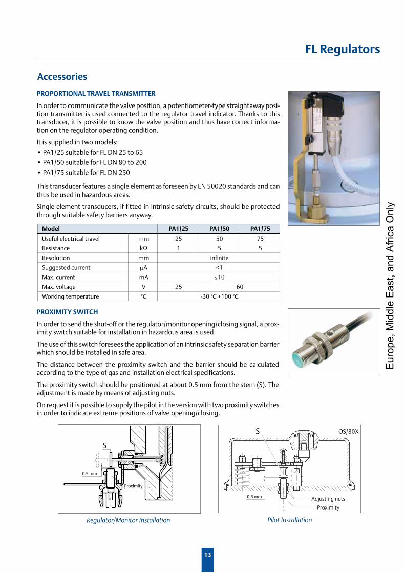
Pilot Installation
Proximity
0.5 mm
S
Regulator/Monitor Installation
OS/80X
Adjusting nuts
Proximity
Accessories
PROPORTIONAL TRAVEL TRANSMITTER
In order to communicate the valve position, a potentiometer-type straightaway posi-tion transmitter is used connected to the regulator travel indicator. Thanks to this transducer, it is possible to know the valve position and thus have correct informa-tion on the regulator operating condition.
It is supplied in two models:
•PA1/25suitableforFLDN25to65
•PA1/50suitableforFLDN80to200
•PA1/75suitableforFLDN250
This transducer features a single element as foreseen by EN 50020 standards and can thus be used in hazardous areas.
Single element transducers, if fitted in intrinsic safety circuits, should be protected through suitable safety barriers anyway.
PROXIMITy SWITCH
In order to send the shut-off or the regulator/monitor opening/closing signal, a prox-imity switch suitable for installation in hazardous area is used.
The use of this switch foresees the application of an intrinsic safety separation barrier which should be installed in safe area.
The distance between the proximity switch and the barrier should be calculated according to the type of gas and installation electrical specifications.
The proximity switch should be positioned at about 0.5 mm from the stem (S). The adjustment is made by means of adjusting nuts.
On request it is possible to supply the pilot in the version with two proximity switches in order to indicate extreme positions of valve opening/closing.
Model PA1/25 PA1/50 PA1/75
Useful electrical travel mm 25 50 75
Resistance kΩ 1 5 5
Resolution mm infinite
Suggested current µA <1
Max. current mA ≤10
Max. voltage V 25 60
Working temperature °C -30 °C +100 °C
Eur
ope,
Mid
dle
Eas
t, an
d A
frica
Onl
y
14
FL Regulators
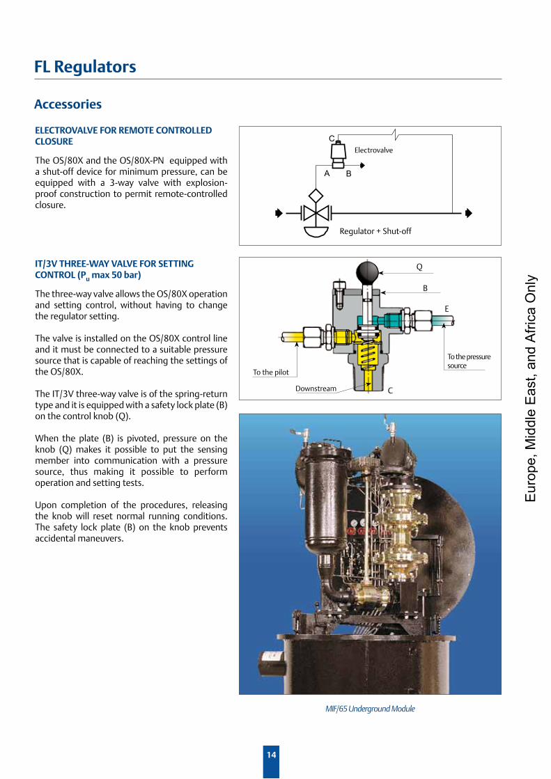
IT/3V THREE-WAy VALVE FOR SETTINGCONTROL (Pu max 50 bar)
The three-way valve allows the OS/80X operation and setting control, without having to change the regulator setting.
The valve is installed on the OS/80X control line and it must be connected to a suitable pressure source that is capable of reaching the settings of the OS/80X.
The IT/3V three-way valve is of the spring-return type and it is equipped with a safety lock plate (B) on the control knob (Q).
When the plate (B) is pivoted, pressure on the knob (Q) makes it possible to put the sensing member into communication with a pressure source, thus making it possible to perform operation and setting tests.
Upon completion of the procedures, releasing the knob will reset normal running conditions. The safety lock plate (B) on the knob prevents accidental maneuvers.
E
CDownstream
To the pressure source
To the pilot
Q
B
ELECTROVALVE FOR REMOTE CONTROLLEDCLOSURE
The OS/80X and the OS/80X-PN equipped with a shut-off device for minimum pressure, can be equipped with a 3-way valve with explosion-proof construction to permit remote-controlled closure.
A B
CElectrovalve
Regulator + Shut-off
MIF/65 Underground Module
Accessories
Eur
ope,
Mid
dle
Eas
t, an
d A
frica
Onl
y
15
FL Regulators
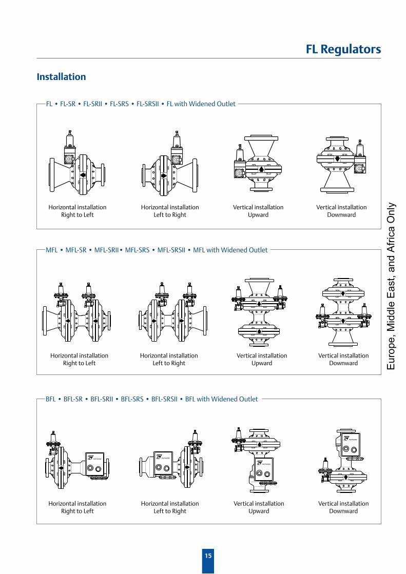
Installation
FL•FL-SR•FL-SRII•FL-SRS•FL-SRSII•FLwithWidenedOutlet
MFL•MFL-SR•MFL-SRII•MFL-SRS•MFL-SRSII•MFLwithWidenedOutlet
BFL•BFL-SR•BFL-SRII•BFL-SRS•BFL-SRSII•BFLwithWidenedOutlet
Horizontal installationRight to Left
Horizontal installationLeft to Right
Vertical installationUpward
Vertical installationDownward
Horizontal installationRight to Left
Horizontal installationLeft to Right
Vertical installationUpward
Horizontal installationRight to Left
Horizontal installationLeft to Right
Vertical installationUpward
Vertical installationDownward
Vertical installationDownward E
urop
e, M
iddl
e E
ast,
and
Afri
ca O
nly
16
FL Regulators
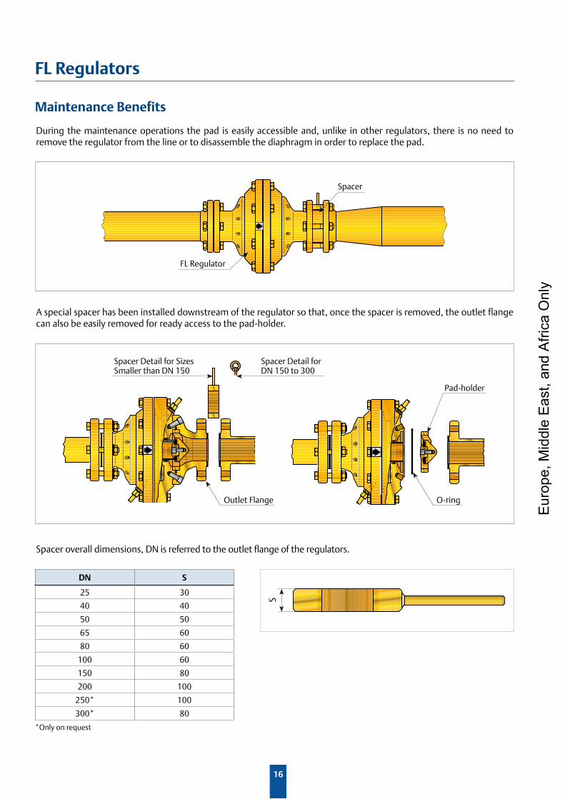
Maintenance Benefits
Pad-holder
During the maintenance operations the pad is easily accessible and, unlike in other regulators, there is no need to remove the regulator from the line or to disassemble the diaphragm in order to replace the pad.
FL Regulator
Spacer
A special spacer has been installed downstream of the regulator so that, once the spacer is removed, the outlet flange can also be easily removed for ready access to the pad-holder.
Spacer overall dimensions, DN is referred to the outlet flange of the regulators.
*Only on request
DN S
25 30
40 40
50 50
65 60
80 60
100 60
150 80
200 100
250* 100
300* 80
Outlet Flange O-ring
Spacer Detail for DN 150 to 300
Spacer Detail for Sizes Smaller than DN 150
S
Eur
ope,
Mid
dle
Eas
t, an
d A
frica
Onl
y
17
FL Regulators
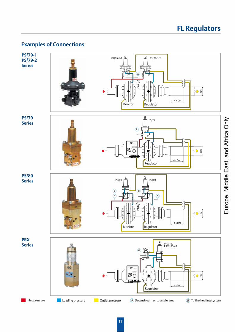
Examples of Connections
PS/79-1-2
A
PS/79-1-2
4 x DN
DN
PS/79
R
4 x DN
DN
TARTARINI
OS/80X
4 x DN
DN
PS/80
n10
R
PS/80
A
R
A
R
4 x DN
DN
TARTARINI
OS/80X
PRX/120PRX/120-AP
SA/2
Monitor Regulator
Regulator
PS/79-1PS/79-2Series
PS/80 Series
PS/79Series
PRXSeries
Monitor Regulator
Regulator
RA Downstream or to a safe area To the heating systemInlet pressure Outlet pressureLoading pressure
Eur
ope,
Mid
dle
Eas
t, an
d A
frica
Onl
y
18
FL Regulators
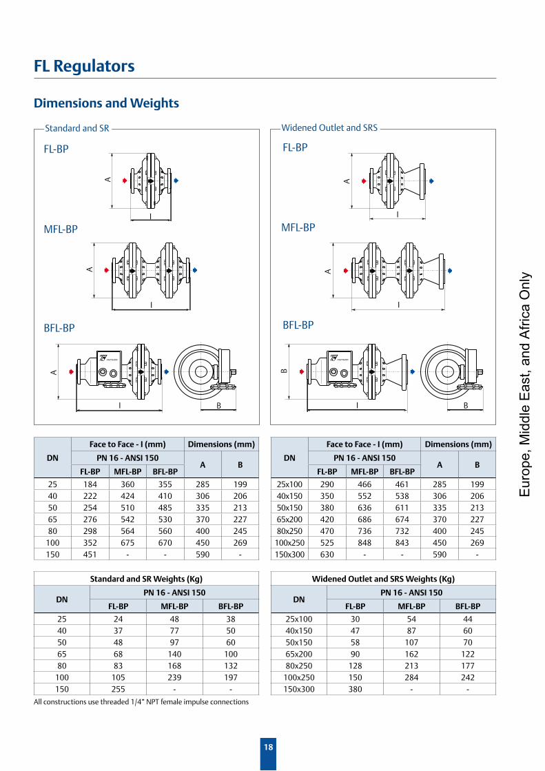
Dimensions and Weights
All constructions use threaded 1/4” NPT female impulse connections
DN
Face to Face - I (mm) Dimensions (mm)
PN 16 - ANSI 150A B
FL-BP MFL-BP BFL-BP
25 184 360 355 285 19940 222 424 410 306 20650 254 510 485 335 21365 276 542 530 370 22780 298 564 560 400 245
100 352 675 670 450 269150 451 - - 590 -
DN
Face to Face - I (mm) Dimensions (mm)
PN 16 - ANSI 150A B
FL-BP MFL-BP BFL-BP
25x100 290 466 461 285 19940x150 350 552 538 306 20650x150 380 636 611 335 21365x200 420 686 674 370 22780x250 470 736 732 400 245
100x250 525 848 843 450 269150x300 630 - - 590 -
Standard and SR Weights (Kg)
DNPN 16 - ANSI 150
FL-BP MFL-BP BFL-BP
25 24 48 3840 37 77 5050 48 97 6065 68 140 10080 83 168 132
100 105 239 197150 255 - -
Widened Outlet and SRS Weights (Kg)
DNPN 16 - ANSI 150
FL-BP MFL-BP BFL-BP
25x100 30 54 4440x150 47 87 6050x150 58 107 7065x200 90 162 12280x250 128 213 177
100x250 150 284 242150x300 380 - -
A
I I
A
FL-BP FL-BP
Widened Outlet and SRSStandard and SR
MFL-BP MFL-BP
I
A
I
A
I
B
B
BFL-BP
I
A
B
BFL-BP
Eur
ope,
Mid
dle
Eas
t, an
d A
frica
Onl
y
19
FL Regulators
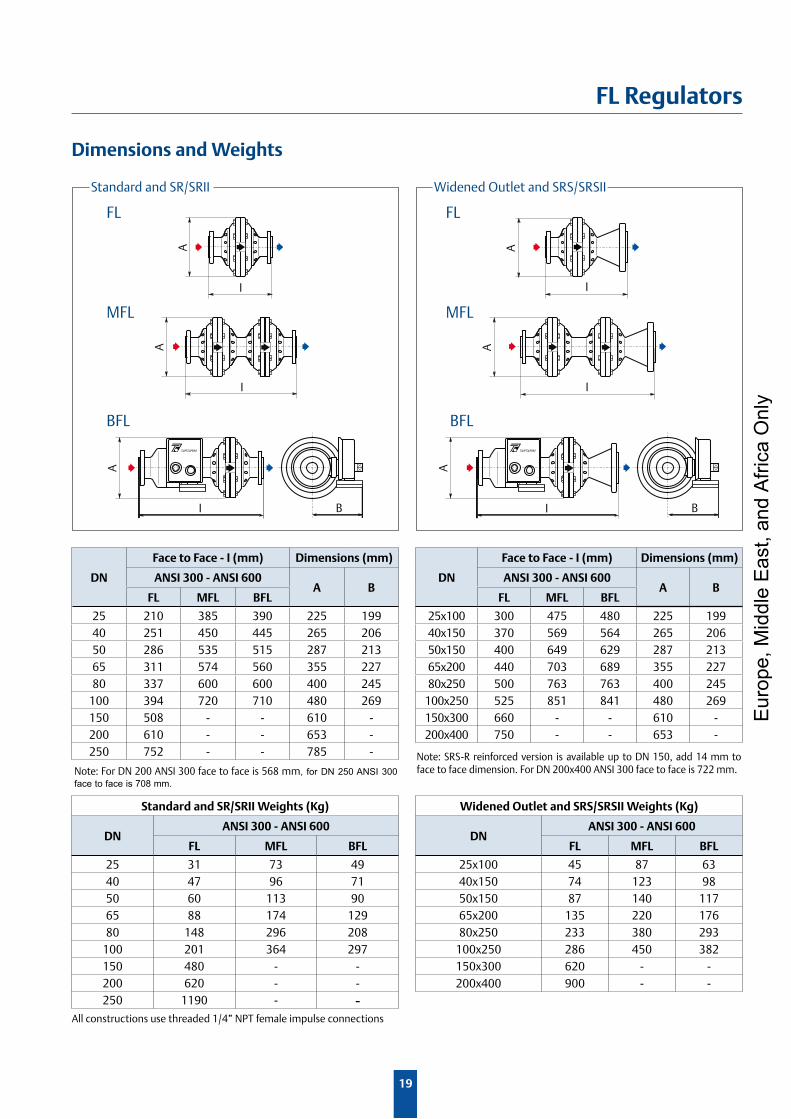
Dimensions and Weights
A
I B
A
I B
A
I
A
I
FL
A
I
I
A
FL
MFL MFL
Widened Outlet and SRS/SRSIIStandard and SR/SRII
BFL BFL
Note: For DN 200 ANSI 300 face to face is 568 mm, for DN 250 ANSI 300 face to face is 708 mm.
DN
Face to Face - I (mm) Dimensions (mm)
ANSI 300 - ANSI 600A B
FL MFL BFL
25 210 385 390 225 19940 251 450 445 265 20650 286 535 515 287 21365 311 574 560 355 22780 337 600 600 400 245
100 394 720 710 480 269150 508 - - 610 -200 610 - - 653 -250 752 - - 785 -
Standard and SR/SRII Weights (Kg)
DNANSI 300 - ANSI 600
FL MFL BFL
25 31 73 4940 47 96 7150 60 113 9065 88 174 12980 148 296 208
100 201 364 297150 480 - -200 620 - -250 1190 - -
DN
Face to Face - I (mm) Dimensions (mm)
ANSI 300 - ANSI 600A B
FL MFL BFL
25x100 300 475 480 225 19940x150 370 569 564 265 20650x150 400 649 629 287 21365x200 440 703 689 355 22780x250 500 763 763 400 245
100x250 525 851 841 480 269150x300 660 - - 610 -200x400 750 - - 653 -
Widened Outlet and SRS/SRSII Weights (Kg)
DNANSI 300 - ANSI 600
FL MFL BFL
25x100 45 87 6340x150 74 123 9850x150 87 140 11765x200 135 220 17680x250 233 380 293
100x250 286 450 382150x300 620 - -200x400 900 - -
Note: SRS-R reinforced version is available up to DN 150, add 14 mm to face to face dimension. For DN 200x400 ANSI 300 face to face is 722 mm.
All constructions use threaded 1/4” NPT female impulse connections
Eur
ope,
Mid
dle
Eas
t, an
d A
frica
Onl
y

Process ManagementTM
© O.M.T. Officina Meccanica Tartarini s.r.l. 2011 ; All Rights Reserved
Natural Gas Technologies
Emerson Process ManagementRegulator Technologies, Inc.
O.M.T.Officina Meccanica Tartarini s.r.l.Via P. Fabbri, 1 I - 40013 Castel Maggiore (Bologna), Italy Tel. : +39 - 0514190611 Fax: +39 - 0514190715 E-mail: [email protected]
The Emerson logo is a trademark and service mark of Emerson Electric Co. All other marks are the property of their prospective owners. Tartarini is a mark owned by O.M.T. Officina Meccanica Tartarini s.r.l., a business of Emerson Process Management.
The contents of this publication are presented for informational purposes only, and while every effort has been made to ensure their accuracy, they are not to be construed as warranties or guarantees, express or implied, regarding the products or services described herein or their use or applicability. We reserve the right to modify or improve the designs or specifications of such products at any time without notice.
O.M.T. Tartarini does not assume responsibility for the selection, use or maintenance of any product. Responsibility for proper selection, use and maintenance of any O.M.T. Tartarini product remains solely with the purchaser.
For further information visit: www.tartarini-naturalgas.com
Natural Gas Technologies
Emerson Process ManagementRegulator Technologies, Inc.
Francel S.A.Z.A. La Croix Saint Mathieu28320 GallardonFranceTel: +33 (0)2 37 33 47 00Fax: +33 (0)2 37 31 46 56
0002EN_FL_BUL - 02/2008 - Rev. 02
Eur
ope,
Mid
dle
Eas
t, an
d A
frica
Onl
y