Embed Size (px)
Citation preview

PRIMERGY
PRIMERGY Econel 100 Server System Options GuideSusanne DäschleinFujitsu Siemens Computers GmbH München81730 Muniche-mail: email: [email protected].: (0 89) 61 001 - 155Fax: (++49) 700 / 372 00000U41627-J-Z156-1-76Sprachen: En
Edition December 2005

Comments… Suggestions… Corrections…The User Documentation Department would like to know your opinion of this manual. Your feedback helps us optimize our documentation to suit your individual needs.
Fax forms for sending us your comments are included in the back of the manual.
There you will also find the addresses of the relevant User Documentation Department.
Certified documentation according to DIN EN ISO 9001:2000To ensure a consistently high quality standard and user-friendliness, this documentation was created to meet the regulations of a quality management system which complies with the requirements of the standard DIN EN ISO 9001:2000.
cognitas. Gesellschaft für Technik-Dokumentation mbH www.cognitas.de
Copyright and TrademarksCopyright © 2005 Fujitsu Siemens Computers GmbH.
All rights reserved. Delivery subject to availability; right of technical modifications reserved.
All hardware and software names used are trademarks of their respective manufacturers.
U41627-J-Z156-1-76 Options Guide
Contents1 Introduction . . . . . . . . . . . . . . . . . . . . . . . . . . . 51.1 Overview of the documentation . . . . . . . . . . . . . . . . . . 51.2 Expansions and conversions . . . . . . . . . . . . . . . . . . . 61.3 Notational conventions . . . . . . . . . . . . . . . . . . . . . . 7
2 Procedure . . . . . . . . . . . . . . . . . . . . . . . . . . . . 9
3 Safety notes . . . . . . . . . . . . . . . . . . . . . . . . . . 11
4 Preparation . . . . . . . . . . . . . . . . . . . . . . . . . . . 174.1 Opening the server . . . . . . . . . . . . . . . . . . . . . . . 174.2 Removing the front panel . . . . . . . . . . . . . . . . . . . . 184.3 Folding out the power supply unit . . . . . . . . . . . . . . . . 194.4 Removing the system fan . . . . . . . . . . . . . . . . . . . . 20
5 Main memory . . . . . . . . . . . . . . . . . . . . . . . . . . 215.1 Equipping rules . . . . . . . . . . . . . . . . . . . . . . . . . 215.2 Extending the main memory . . . . . . . . . . . . . . . . . . 22
6 Accessible drives . . . . . . . . . . . . . . . . . . . . . . . 256.1 Installing a CD/DVD/tape drive . . . . . . . . . . . . . . . . . 266.1.1 Connecting the drives . . . . . . . . . . . . . . . . . . . . . . 286.2 Installing the floppy disk drive . . . . . . . . . . . . . . . . . . 29
7 SATA hard disk drives . . . . . . . . . . . . . . . . . . . . . 337.1 Installing a SATA hard disk drive . . . . . . . . . . . . . . . . 33
8 Controllers in PCI slots . . . . . . . . . . . . . . . . . . . . 398.1 Installing a standard PCI controller . . . . . . . . . . . . . . . 398.2 Installing a low-profile PCI controller . . . . . . . . . . . . . . 41
9 Completion . . . . . . . . . . . . . . . . . . . . . . . . . . . 439.1 Mounting the system fan . . . . . . . . . . . . . . . . . . . . 439.2 Folding in the power supply unit . . . . . . . . . . . . . . . . . 449.3 Mounting the front cover . . . . . . . . . . . . . . . . . . . . . 459.4 Closing the server . . . . . . . . . . . . . . . . . . . . . . . . 46
Options Guide U41627-J-Z156-1-76
Contents
10 Appendix . . . . . . . . . . . . . . . . . . . . . . . . . . . . 4710.1 Cabling . . . . . . . . . . . . . . . . . . . . . . . . . . . . . 47
Abbreviations . . . . . . . . . . . . . . . . . . . . . . . . . . . . . . . 49
Related publications . . . . . . . . . . . . . . . . . . . . . . . . . . . 55
Index . . . . . . . . . . . . . . . . . . . . . . . . . . . . . . . . . . . . 57
U41627-J-Z156-1-76 Options Guide 5
1 IntroductionThe PRIMERGY Econel 100 server is an Intel-based server for small and mid-size networks. The server is suitable for use as a file server and also as an application, information or Internet server.
1.1 Overview of the documentation
I PRIMERGY manuals are available in PDF format on the ServerBooks CD which is supplied in the ServerView Suite package for every server system.
These PDF files can also be downloaded free of charge from the Internet: at http://manuals.fujitsu-siemens.com you will find an overview page with the online documentation available on the Internet. You can go to the PRIMERGY Server documentation by clicking on “industry standard servers”.
Concept and target groups
This Options Guide shows you how you can expand and upgrade the server.
The activities described in this manual may only be performed by technical specialists.
Additional documentation about the server
The PRIMERGY Econel 100 documentation comprises the following additional manuals:
– “Quick Start Hardware - PRIMERGY Econel100” (poster)– “Quick Start Software - PRIMERGY ServerView Suite” (poster)– “Warranty” manual (print version delivered together with the system, PDF file
available on the ServerBooks CD)– “Safety” manual (print version delivered together with the system, PDF file
available on the ServerBooks CD)– “Ergonomics” manual (PDF file available on the ServerBooks CD)– “Returning used devices” (PDF file available on the ServerBooks CD)– “Help Desk” (poster with worldwide help desk telephone numbers)– “PRIMERGY Econel 100 Server System Operating Manual” (PDF file
available on the ServerBooks CD)
6 Options Guide U41627-J-Z156-1-76
Expansions and conversions Introduction
– Technical Manual for the system board D2179 (PDF file available on the ServerBooks CD)
– “BIOS Setup” manual (PDF file available on the ServerBooks CD)– “ServerView Suite” includes the ServerStart CD, the ServerBooks CD and the
print version of the manual “PRIMERGY ServerView Suite - ServerStart”. The PDF file of the manual is also available on the ServerBooks CD.
– “LSI SATA Software RAID User’s Guide” (PDF file available on the ServerBooks CD)
I If you need a backup of the ServerBooks CD send the details of your server via E-mail address: [email protected]
Further sources of information:
– manual for the monitor– manual for ServerView server management– documentation for the boards and drives– operating system documentation– information files of your operating system
(see also “Related publications” on page 55)
1.2 Expansions and conversions
Extension of the main memory
The system board supports up to 8 Gbyte main memory. 4 slots are available for the main memory. Each slot can be populated with 512 Mbyte, 1 Gbyte or 2 Gbyte PC2-4200 DDR2 533 MHz (unbuffered) DIMMmemory modules.
Additional accessible drives
Two free 5.25-inch bays for additional accessible drives and one 3.5-inch bay for a 1.44 MB floppy disk drive are available. If a backup drive (tape) is to be installed a PCI SCSI controller is needed.
The highest, first bay is already occupied with a DVD drive.
SATA hard disk drives
Up to four SATA hard disk drives can be installed.
U41627-J-Z156-1-76 Options Guide 7
Introduction Notational conventions
Additional controllers in the PCI slots
The system board offers three PCI-E (Express) slots and four standard PCI slots (33 MHz) for additional controllers.
1.3 Notational conventions
The following notational conventions are used in this manual:
text in italics indicate commands, menu items or software programs.
“quotation marks” indicate names of chapters and terms that are being emphasized.
Ê describes activities that must be performed in the order shown
V CAUTION! Pay particular attention to texts marked with this symbol. Failure to observe this warning may endanger your life, destroy the system or lead to the loss of data.
I indicates additional information, notes and tips
Table 1: Notational conventions

U41627-J-Z156-1-76 Options Guide 9
2 ProcedureV CAUTION!
The actions described in this manual should only be performed by technical specialists. Equipment repairs should only be performed by service personnel. Any failure to observe the guidelines in this manual, and any unauthorized openings and improper repairs could expose the user to risks (electric shock, energy hazards, fire hazards) and could also damage the equipment. Please note that any unauthorized openings of the device will result in the invalidation of the warranty and exclusion from all liability.
Ê At first, please take notice of chapter “Safety notes” on page 11 and following.
Ê Make sure all necessary manuals (see “Additional documentation about the server” on page 5) are available; possibly print of the PDF files. You will definitely need the Operating Manual for the server and the Technical Manual for the system board.
Ê Shut down the server correctly, switch it OFF, pull out the power plug, and open the server as described in the chapter “Preparation” on page 17 and following.
Ê Expand or upgrade your server as described in the relevant chapter.
Ê Close the server, connect it to the mains, and switch it ON as described in chapter “Completion” on page 43 and following.
Ê Start the operating system and, if necessary, configure it as required (see Operating Manual).

U41627-J-Z156-1-76 Options Guide 11
3 Safety notesI The following safety notes are also provided in the “Safety” manual.
This device complies with the relevant safety regulations for data processing equipment.
If you have any questions about where you can set up the device, contact your sales outlet or our customer service team.
V CAUTION!
The actions described in this manual should only be performed by technical specialists. Any repairs on the device must be performed by authorized, technically qualified personnel. Any unauthorized openings and improper repairs could expose the user to risks (electric shock, energy hazards, fire hazards) and could also damage the equipment. Please note that any unauthorized openings of the device will result in the invalidation of the warranty and exclusion from all liability.
Before operating the device
V CAUTION!
● During installation and before operating the device, observe the instructions on environmental conditions for your device.
● If the device is brought in from a cold environment, condensation may form both inside and on the outside of the machine.
Wait until the device has acclimatized to room temperature and is absolutely dry before starting it up. Material damage may be caused to the device if this requirement is not observed.
● Transport the device in its original packaging or in other suitable packaging which will protect it against shock or impact.
12 Options Guide U41627-J-Z156-1-76
Safety
Installation and operation
V CAUTION!
● If the server is integrated in an installation that receives power from an industrial (public) power supply network with the IEC309 connector, the (public) power supply protection must comply with the requirements for the non-industrial (public) power supply networks for the type A connector.
● The server automatically sets itself to a voltage in the range of 100 V to 240 V. Make sure that your local voltage is within this range.
● This device has a specially approved power cable and must only be connected to a grounded insulated socket.
● Ensure that the power socket on the device or the grounded wall outlet is freely accessible.
● The power switch or the main power switch does not disconnect the device from the mains voltage. To disconnect the line voltage completely, remove the power plug from the grounded insulated socket.
● Always connect the device and the attached peripherals to the same power circuit. Otherwise you run the risk of losing data if, for example, the central processing unit is still running but the peripheral device (e.g. storage subsystem) has failed during a power outage.
● Data cables must be adequately shielded.
● To the LAN wiring the requirements apply in accordance with the standards EN 50173 and EN 50174-1/2. As minimum requirement the use of a protected LAN line of category 5 for 10/100 MBps Ethernet, and/or of category 5e for Gigabit Ethernet is considered. The requirements of the specification ISO/IEC 11801 are to be considered.
● Route the cables in such a way that they do not form a potential hazard (make sure no-one can trip over them) and that they cannot be damaged. When connecting up a device, refer to the relevant notes in this manual.
U41627-J-Z156-1-76 Options Guide 13
Safety
V CAUTION!
● Never connect or disconnect data transmission lines during a storm (lightning hazard).
● Otherwise you run the risk of losing data if, for example, the central processing unit is still running but the peripheral device (e.g. storage subsystem) has failed during a power outage.
● In emergencies (e.g. damaged casing, controls or cables, penetration of liquids or foreign matter), switch OFF the device immediately, remove the power plug and contact your sales outlet or customer service team.
● Proper operation of the system (in accordance with IEC 60950/EN 60950) is only ensured if the casing is completely assembled and the rear covers for the installation openings have been put in place (electric shock, cooling, fire protection, interference suppression).
● Only install system expansions that satisfy the requirements and rules governing safety and electromagnetic compatibility and relating to telecommunications terminal equipment. If you install other expan-sions, you may damage the system or violate the safety regulations and regulations governing RFI suppression. Information on which system expansions are suitable can be obtained from the customer service centre or your sales outlet.
● The components or parts marked with a warning label (e.g. lightning symbol) may only be opened, removed or exchanged by authorized, qualified personnel.
● The warranty expires if the device is damaged during the installation or replacement of system expansions.
● You may only set those resolutions and refresh rates specified in the “Technical data” section of the monitor description. Otherwise, you may damage your monitor. If you are in any doubt, contact your sales outlet or customer service centre.
14 Options Guide U41627-J-Z156-1-76
Safety
Batteries
V CAUTION!
● Incorrect replacement of batteries may lead to a risk of explosion. The batteries may only be replaced with identical batteries or with a type recommended by the manufacturer (see the technical manual for the system board under “Related publications” on page 55).
● Replace the lithium battery on the system board in accordance with the instructions in the technical manual for the system board (see “Related publications” on page 55).
Notes on handling CDs/DVDs and CD/DVD drives
V CAUTION!
● Use only CDs/DVDs in proper condition in the CD/DVD drive of your server to prevent data loss, damage to the device and injuries.
● Therefore, check each CD/DVD for damage, cracks, breakage etc. before inserting it in the drive.
Please note that any additional labels applied may change the mechanical properties of a CD/DVD and cause imbalance.
Damaged and imbalanced CDs/DVDs can break at high drive speeds (data loss).
Under certain conditions sharp-edged pieces of broken CDs/DVDs can penetrate the cover of the drive (damage to the device) and be thrown out of the device (danger of injury, particularly on uncovered body parts such as the face or neck).
I You protect the CD/DVD drive and prevent mechanical damage, as well as premature wearing of the CDs/DVDs, by observing the following suggestions:
– Only insert the CDs/DVDs in the drive when needed and remove them after use.
– Store the CDs/DVDs in suitable sleeves.– Protect the CDs/DVDs from exposure to heat and direct sunlight.
U41627-J-Z156-1-76 Options Guide 15
Safety
Note about the laser
The CD/DVD drive is classified for laser class 1 according to IEC 60825-1.
V CAUTION!
The CD/DVD drive contains a laser diode (LED). Sometimes the LED produces a stronger laser beam than laser class 1. Direct view into the laser beam is dangerous.
Never remove parts of the CD/DVD drive assembly!
Modules with electrostatic-sensitive components
Systems and components that might be damaged by electrostatic discharge (ESD) are marked with the following label:
Figure 1: ESD label
When you handle components fitted with ESDs, you must observe the following points under all circumstances:
● Remove the power plug from the power socket before inserting or removing components containing ESDs.
● You must always discharge yourself of static charges (e.g. by touching a grounded object) before working.
● The equipment and tools you use must be free of static charges.
● Use a grounding cable designed for this purpose to connect yourself to the system unit as you install components.
● Only touch the components at the positions highlighted in green (touch point).
● Do not touch any exposed pins or conductors on a component.
16 Options Guide U41627-J-Z156-1-76
Safety
● Place all components on a static-safe base.
I You will find a detailed description for handling ESD components in the relevant European or international standards (EN 61340-5-1, ANSI/ESD S20.20).
U41627-J-Z156-1-76 Options Guide 17
4 PreparationV CAUTION!
Refer to the safety notes in chapter “Safety notes” on page 11 and following.
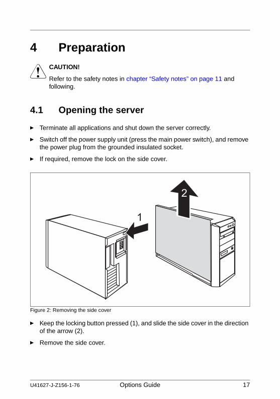
4.1 Opening the server
Ê Terminate all applications and shut down the server correctly.
Ê Switch off the power supply unit (press the main power switch), and remove the power plug from the grounded insulated socket.
Ê If required, remove the lock on the side cover.
Figure 2: Removing the side cover
Ê Keep the locking button pressed (1), and slide the side cover in the direction of the arrow (2).
Ê Remove the side cover.
18 Options Guide U41627-J-Z156-1-76
Removing the front panel Preparation
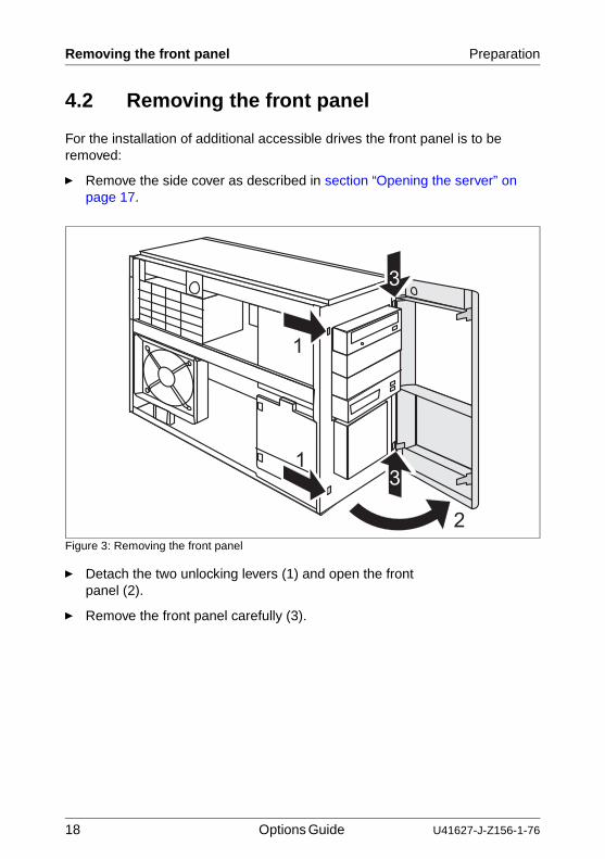
4.2 Removing the front panel
For the installation of additional accessible drives the front panel is to be removed:
Ê Remove the side cover as described in section “Opening the server” on page 17.
Figure 3: Removing the front panel
Ê Detach the two unlocking levers (1) and open the front panel (2).
Ê Remove the front panel carefully (3).
U41627-J-Z156-1-76 Options Guide 19
Preparation Folding out the power supply unit
4.3 Folding out the power supply unit
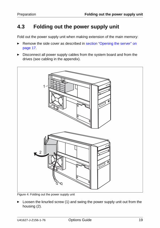
Fold out the power supply unit when making extension of the main memory:
Ê Remove the side cover as described in section “Opening the server” on page 17.
Ê Disconnect all power supply cables from the system board and from the drives (see cabling in the appendix).
Figure 4: Folding out the power supply unit
Ê Loosen the knurled screw (1) and swing the power supply unit out from the housing (2).
20 Options Guide U41627-J-Z156-1-76
Removing the system fan Preparation
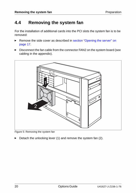
4.4 Removing the system fan
For the installation of additional cards into the PCI slots the system fan is to be removed:
Ê Remove the side cover as described in section “Opening the server” on page 17.
Ê Disconnect the fan cable from the connector FAN2 on the system board (see cabling in the appendix).
Figure 5: Removing the system fan
Ê Detach the unlocking lever (1) and remove the system fan (2).
U41627-J-Z156-1-76 Options Guide 21
5 Main memoryV CAUTION!
Refer to the safety notes in chapter “Safety notes” on page 11 and following.
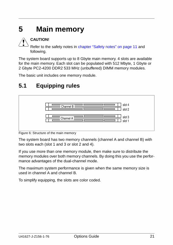
The system board supports up to 8 Gbyte main memory. 4 slots are available for the main memory. Each slot can be populated with 512 Mbyte, 1 Gbyte or 2 Gbyte PC2-4200 DDR2 533 MHz (unbuffered) DIMM memory modules.
The basic unit includes one memory module.
5.1 Equipping rules
Figure 6: Structure of the main memory
The system board has two memory channels (channel A and channel B) with two slots each (slot 1 and 3 or slot 2 and 4).
If you use more than one memory module, then make sure to distribute the memory modules over both memory channels. By doing this you use the perfor-mance advantages of the dual-channel mode.
The maximum system performance is given when the same memory size is used in channel A and channel B.
To simplify equipping, the slots are color coded.
slot 1slot 3
slot 4slot 2
Channel B
Channel A
22 Options Guide U41627-J-Z156-1-76
Extending the main memory Main memory
Following table shows the mandatory population order.
If you install three memory modules equip the following slots: channel A (slot 1 and slot 3), channel B (slot 2).
With a dual channel configuration identical memory modules are to be used for the individual population possibilities.
5.2 Extending the main memory
Ê Open the server and fold out the power supply unit as described in chapter “Preparation” on page 17 and following.
Ê Unpack the memory module.
mode option slotslot 1 slot 3 slot 2 slot 4
single channel
channel A equippedequipped
channel B equippedequipped
dual channel
channel A+B
equipped equippedequipped equipped
equipped equipped equipped equipped
Table 2: Memory modules population
U41627-J-Z156-1-76 Options Guide 23
Main memory Extending the main memory
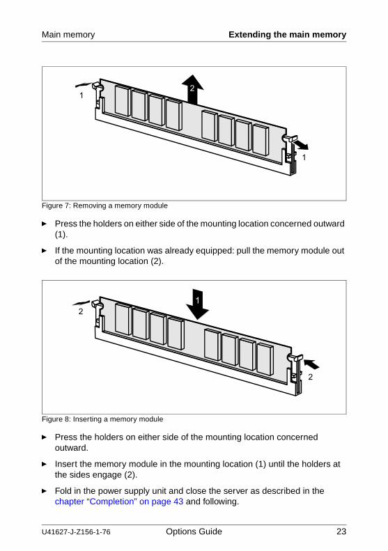
Figure 7: Removing a memory module
Ê Press the holders on either side of the mounting location concerned outward (1).
Ê If the mounting location was already equipped: pull the memory module out of the mounting location (2).
Figure 8: Inserting a memory module
Ê Press the holders on either side of the mounting location concerned outward.
Ê Insert the memory module in the mounting location (1) until the holders at the sides engage (2).
Ê Fold in the power supply unit and close the server as described in the chapter “Completion” on page 43 and following.
1
12
2
2

U41627-J-Z156-1-76 Options Guide 25
6 Accessible drivesV CAUTION!
Refer to the safety notes in chapter “Safety notes” on page 11 and following.
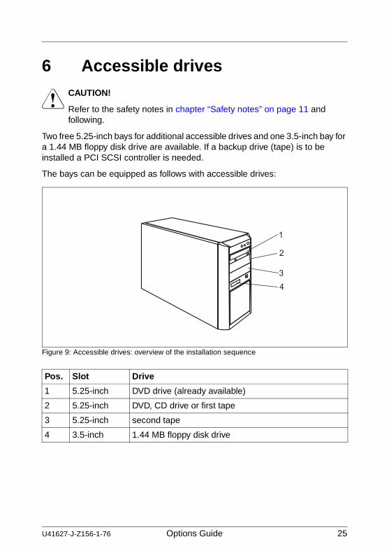
Two free 5.25-inch bays for additional accessible drives and one 3.5-inch bay for a 1.44 MB floppy disk drive are available. If a backup drive (tape) is to be installed a PCI SCSI controller is needed.
The bays can be equipped as follows with accessible drives:
Figure 9: Accessible drives: overview of the installation sequence
Pos. Slot Drive
1 5.25-inch DVD drive (already available)
2 5.25-inch DVD, CD drive or first tape
3 5.25-inch second tape
4 3.5-inch 1.44 MB floppy disk drive
26 Options Guide U41627-J-Z156-1-76
Installing a CD/DVD/tape drive Accessible drives
6.1 Installing a CD/DVD/tape drive
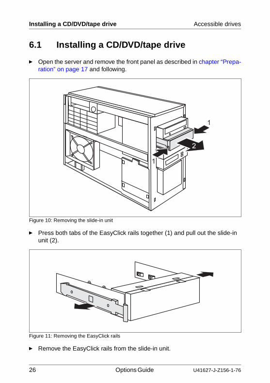
Ê Open the server and remove the front panel as described in chapter “Prepa-ration” on page 17 and following.
Figure 10: Removing the slide-in unit
Ê Press both tabs of the EasyClick rails together (1) and pull out the slide-in unit (2).
Figure 11: Removing the EasyClick rails
Ê Remove the EasyClick rails from the slide-in unit.
U41627-J-Z156-1-76 Options Guide 27
Accessible drives Installing a CD/DVD/tape drive
V CAUTION!
Keep the slide-in unit for future use. If the drive is removed again and not replaced with a new drive, the slide-in unit must be reinstalled due to cooling, to comply with applicable EMC regulations (regulations on electromagnetic compatibility) and to protect against fire.
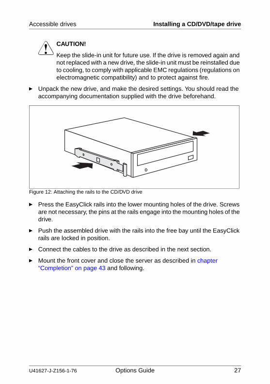
Ê Unpack the new drive, and make the desired settings. You should read the accompanying documentation supplied with the drive beforehand.
Figure 12: Attaching the rails to the CD/DVD drive
Ê Press the EasyClick rails into the lower mounting holes of the drive. Screws are not necessary, the pins at the rails engage into the mounting holes of the drive.
Ê Push the assembled drive with the rails into the free bay until the EasyClick rails are locked in position.
Ê Connect the cables to the drive as described in the next section.
Ê Mount the front cover and close the server as described in chapter “Completion” on page 43 and following.
28 Options Guide U41627-J-Z156-1-76
Installing a CD/DVD/tape drive Accessible drives
6.1.1 Connecting the drives
Ê Connect the power cable connector P3, P4 or P5 to the relevant power connector of the drive. You should read the accompanying documentation supplied with the drive beforehand.
IDE drive (CD/DVD)
Ê Connect the second connector of the existing IDE cable T26139-Y1737-V111 (flat band cable) to the relevant IDE port of the CD/DVD drive. You should read the accompanying documentation supplied with the drive beforehand.
SCSI drives (tape)
For the operation of additional backup drives (tape) a PCI SCSI controller is needed. The PCI SCSI controller will be installed in one of the seven PCI slots (1-7) (see chapter “Controllers in PCI slots” on page 39).
Ê Connect the SCSI cable T26139-Y3859-V11/T26139-Y3576-V209 (flat band cable delivered with the SCSI controller) to the relevant SCSI interface of the tape drive. You should read the accompanying documentation supplied with the drive and/or the controller beforehand.
Ê Connect the SCSI cable to the SCSI interface of the SCSI controller. You should read the accompanying documentation supplied with the drive and/or the controller beforehand.
U41627-J-Z156-1-76 Options Guide 29
Accessible drives Installing the floppy disk drive
6.2 Installing the floppy disk drive
Ê Open the server and remove the front panel as described in chapter “Prepa-ration” on page 17 and following.
Ê Remove the connector of the USB front cable from the connector USB front on the system board.
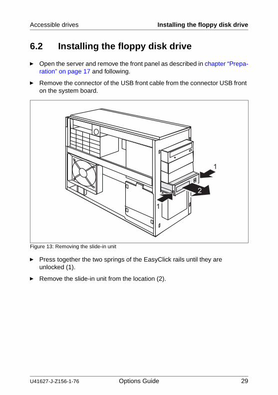
Figure 13: Removing the slide-in unit
Ê Press together the two springs of the EasyClick rails until they are unlocked (1).
Ê Remove the slide-in unit from the location (2).
30 Options Guide U41627-J-Z156-1-76
Installing the floppy disk drive Accessible drives
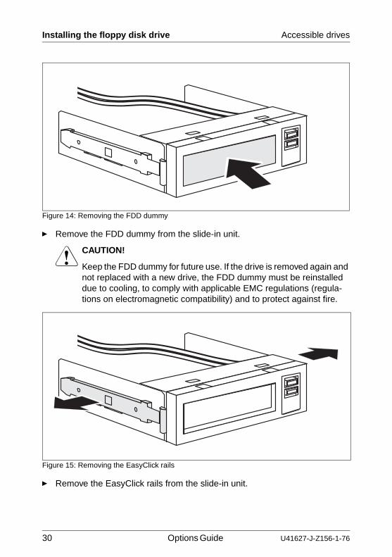
Figure 14: Removing the FDD dummy
Ê Remove the FDD dummy from the slide-in unit.
V CAUTION!
Keep the FDD dummy for future use. If the drive is removed again and not replaced with a new drive, the FDD dummy must be reinstalled due to cooling, to comply with applicable EMC regulations (regula-tions on electromagnetic compatibility) and to protect against fire.
Figure 15: Removing the EasyClick rails
Ê Remove the EasyClick rails from the slide-in unit.
U41627-J-Z156-1-76 Options Guide 31
Accessible drives Installing the floppy disk drive
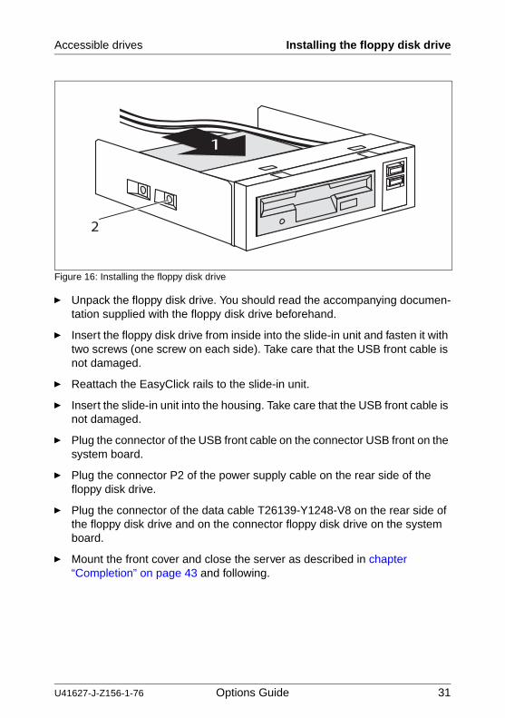
Figure 16: Installing the floppy disk drive
Ê Unpack the floppy disk drive. You should read the accompanying documen-tation supplied with the floppy disk drive beforehand.
Ê Insert the floppy disk drive from inside into the slide-in unit and fasten it with two screws (one screw on each side). Take care that the USB front cable is not damaged.
Ê Reattach the EasyClick rails to the slide-in unit.
Ê Insert the slide-in unit into the housing. Take care that the USB front cable is not damaged.
Ê Plug the connector of the USB front cable on the connector USB front on the system board.
Ê Plug the connector P2 of the power supply cable on the rear side of the floppy disk drive.
Ê Plug the connector of the data cable T26139-Y1248-V8 on the rear side of the floppy disk drive and on the connector floppy disk drive on the system board.
Ê Mount the front cover and close the server as described in chapter “Completion” on page 43 and following.

U41627-J-Z156-1-76 Options Guide 33
7 SATA hard disk drivesV CAUTION!
Refer to the safety notes in chapter “Safety notes” on page 11 and following.
7.1 Installing a SATA hard disk drive
Up to three additional SATA hard disk drives can be installed.
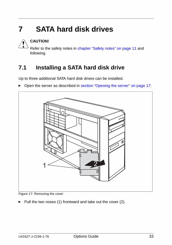
Ê Open the server as described in section “Opening the server” on page 17.
Figure 17: Removing the cover
Ê Pull the two noses (1) frontward and take out the cover (2).
34 Options Guide U41627-J-Z156-1-76
Installing a SATA hard disk drive SATA hard disk drives
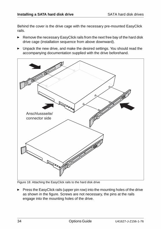
Behind the cover is the drive cage with the necessary pre-mounted EasyClick rails.
Ê Remove the necessary EasyClick rails from the next free bay of the hard disk drive cage (installation sequence from above downward).
Ê Unpack the new drive, and make the desired settings. You should read the accompanying documentation supplied with the drive beforehand.
Figure 18: Attaching the EasyClick rails to the hard disk drive
Ê Press the EasyClick rails (upper pin row) into the mounting holes of the drive as shown in the figure. Screws are not necessary, the pins at the rails engage into the mounting holes of the drive.
Anschlussseite/
connector side
U41627-J-Z156-1-76 Options Guide 35
SATA hard disk drives Installing a SATA hard disk drive
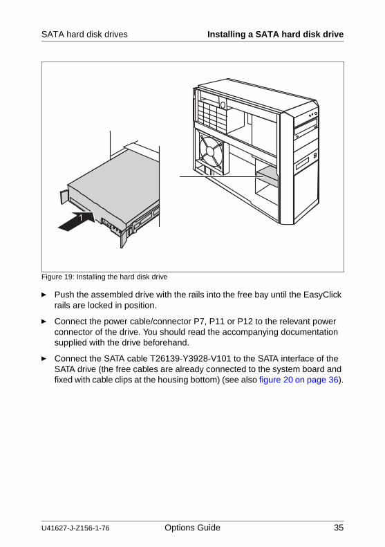
Figure 19: Installing the hard disk drive
Ê Push the assembled drive with the rails into the free bay until the EasyClick rails are locked in position.
Ê Connect the power cable/connector P7, P11 or P12 to the relevant power connector of the drive. You should read the accompanying documentation supplied with the drive beforehand.
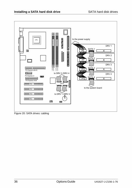
Ê Connect the SATA cable T26139-Y3928-V101 to the SATA interface of the SATA drive (the free cables are already connected to the system board and fixed with cable clips at the housing bottom) (see also figure 20 on page 36).
36 Options Guide U41627-J-Z156-1-76
Installing a SATA hard disk drive SATA hard disk drives
Figure 20: SATA drives: cabling
PCI
PCI
PCI
PCI
PCI Express x1
PCI Express x4/x8slot 1slot 3
slot 4slot 2
Cha
nn
elB
Cha
nn
elA
PCI Express x8/x16
U41627-J-Z156-1-76 Options Guide 37
SATA hard disk drives Installing a SATA hard disk drive
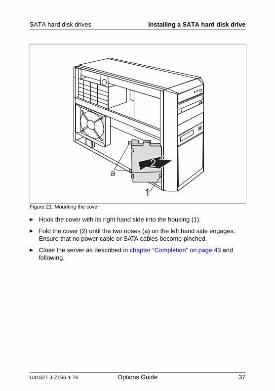
Figure 21: Mounting the cover
Ê Hook the cover with its right hand side into the housing (1).
Ê Fold the cover (2) until the two noses (a) on the left hand side engages. Ensure that no power cable or SATA cables become pinched.
Ê Close the server as described in chapter “Completion” on page 43 and following.

U41627-J-Z156-1-76 Options Guide 39
8 Controllers in PCI slotsV CAUTION!
Refer to the safety notes in chapter “Safety notes” on page 11 and following.
The system board offers three PCI-E (Express) slots and four standard PCI slots (33 MHz) for additional controllers. The numbering of the slots takes place from above downward (1-7). Four slots (1, 3, 5 and 7) are suitable also for low-profile cards.
8.1 Installing a standard PCI controller
Ê Open the server and remove the system fan as described in chapter “Prepa-ration” on page 17 and following.
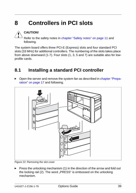
Figure 22: Removing the slot cover
Ê Press the unlocking mechanism (1) in the direction of the arrow and fold out the locking rail (2). The word „PRESS“ is embossed on the unlocking mechanism.
40 Options Guide U41627-J-Z156-1-76
Installing a standard PCI controller Controllers in PCI slots
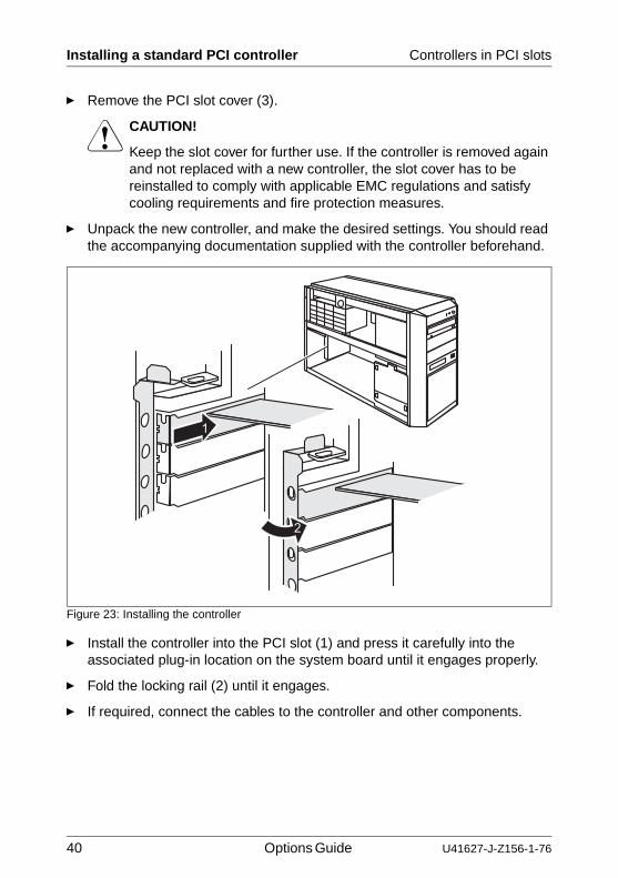
Ê Remove the PCI slot cover (3).
V CAUTION!
Keep the slot cover for further use. If the controller is removed again and not replaced with a new controller, the slot cover has to be reinstalled to comply with applicable EMC regulations and satisfy cooling requirements and fire protection measures.
Ê Unpack the new controller, and make the desired settings. You should read the accompanying documentation supplied with the controller beforehand.
Figure 23: Installing the controller
Ê Install the controller into the PCI slot (1) and press it carefully into the associated plug-in location on the system board until it engages properly.
Ê Fold the locking rail (2) until it engages.
Ê If required, connect the cables to the controller and other components.
U41627-J-Z156-1-76 Options Guide 41
Controllers in PCI slots Installing a low-profile PCI controller
Ê Mount the system fan and close the server as described in chapter “Completion” on page 43 and following.
I Please check the relevant PCI slot settings in the BIOS-Setup. If necessary, change the settings. Please read the documentation for the installed PCI card.
Pay attention to the allocation of the PCI interrupts. You find further infor-mation in the Technical Manual for the system board D2179 (PDF file available on the ServerBooks CD).
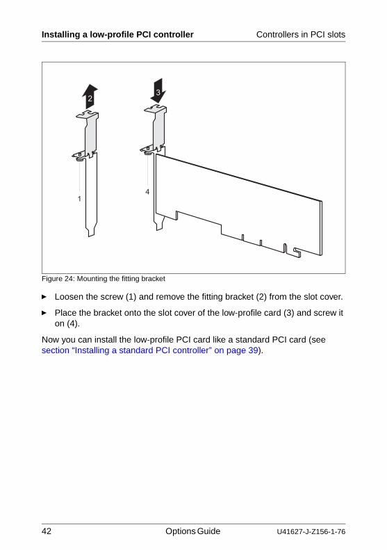
8.2 Installing a low-profile PCI controller
The four standard PCI slots are suitable for installing low-profile cards. These slots are provided with two-piece covers. In order to install a low-profile card a part of this two-piece cover is to be mounted as fitting bracket onto the slot cover of the card.
Ê Remove the slot cover from the PCI slot as shown in figure “Removing the slot cover” on page 39.
V CAUTION!
Keep the slot cover for further use. If the controller is removed again and not replaced with a new controller, the slot cover has to be reinstalled to comply with applicable EMC regulations and satisfy cooling requirements and fire protection measures.
Ê Unpack the new controller, and make the desired settings. You should read the accompanying documentation supplied with the controller beforehand.
42 Options Guide U41627-J-Z156-1-76
Installing a low-profile PCI controller Controllers in PCI slots
Figure 24: Mounting the fitting bracket
Ê Loosen the screw (1) and remove the fitting bracket (2) from the slot cover.
Ê Place the bracket onto the slot cover of the low-profile card (3) and screw it on (4).
Now you can install the low-profile PCI card like a standard PCI card (see section “Installing a standard PCI controller” on page 39).
U41627-J-Z156-1-76 Options Guide 43
9 CompletionV CAUTION!
Refer to the safety notes in chapter “Safety notes” on page 11 and following.
9.1 Mounting the system fan
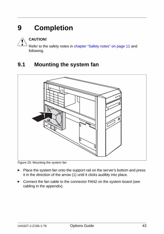
Figure 25: Mounting the system fan
Ê Place the system fan onto the support rail on the server’s bottom and press it in the direction of the arrow (1) until it clicks audibly into place.
Ê Connect the fan cable to the connector FAN2 on the system board (see cabling in the appendix).
44 Options Guide U41627-J-Z156-1-76
Folding in the power supply unit Completion
9.2 Folding in the power supply unit
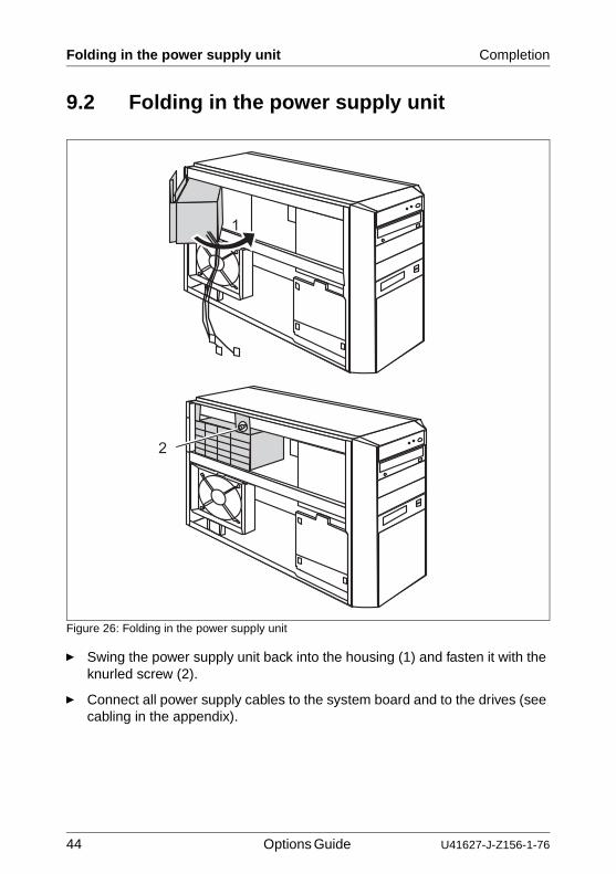
Figure 26: Folding in the power supply unit
Ê Swing the power supply unit back into the housing (1) and fasten it with the knurled screw (2).
Ê Connect all power supply cables to the system board and to the drives (see cabling in the appendix).
U41627-J-Z156-1-76 Options Guide 45
Completion Mounting the front cover
9.3 Mounting the front cover
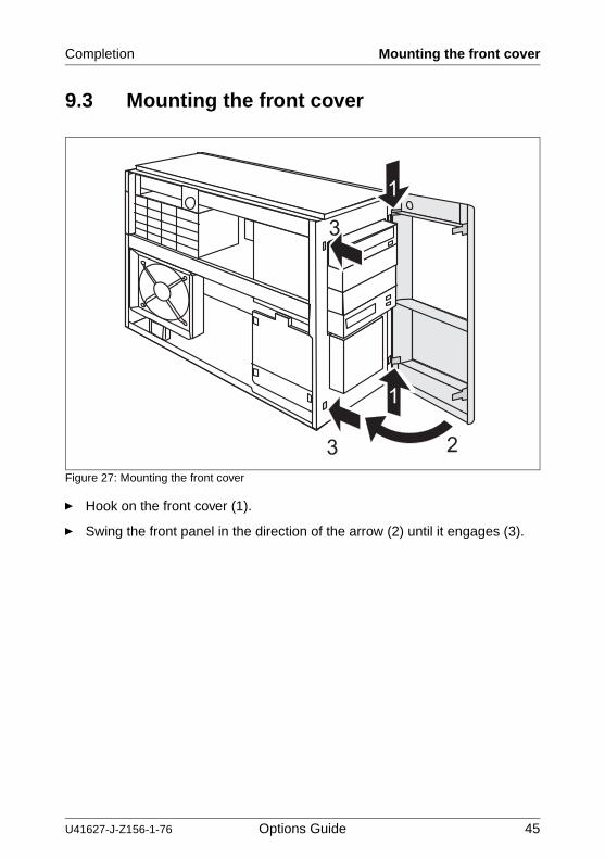
Figure 27: Mounting the front cover
Ê Hook on the front cover (1).
Ê Swing the front panel in the direction of the arrow (2) until it engages (3).
46 Options Guide U41627-J-Z156-1-76
Closing the server Completion
9.4 Closing the server
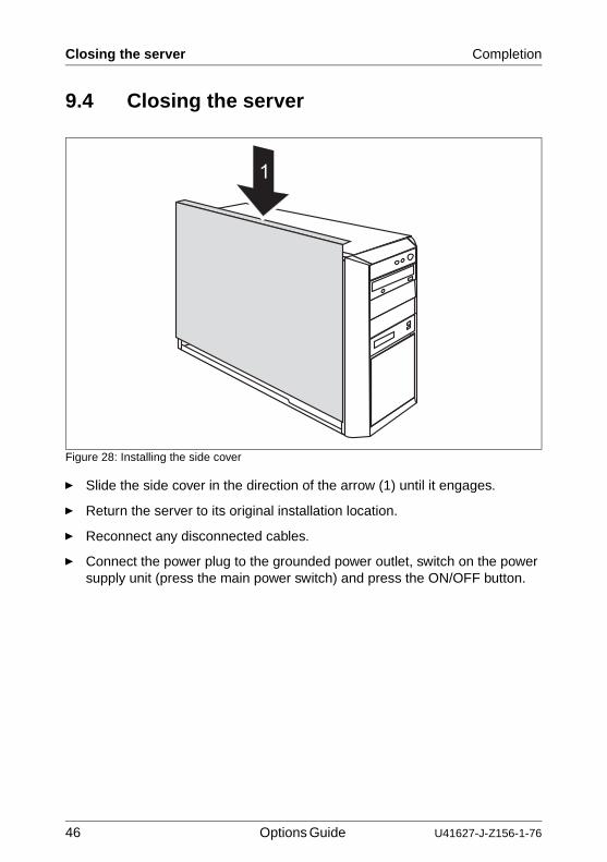
Figure 28: Installing the side cover
Ê Slide the side cover in the direction of the arrow (1) until it engages.
Ê Return the server to its original installation location.
Ê Reconnect any disconnected cables.
Ê Connect the power plug to the grounded power outlet, switch on the power supply unit (press the main power switch) and press the ON/OFF button.
U41627-J-Z156-1-76 Options Guide 47
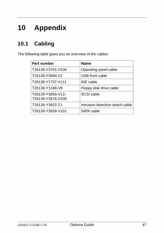
10 Appendix
10.1 Cabling
The following table gives you an overview of the cables:
Part number Name
T26139-Y3701-V106 Operating panel cable
T26139-Y3894-V2 USB front cable
T26139-Y1737-V111 IDE cable
T26139-Y1248-V8 Floppy disk drive cable
T26139-Y3859-V11/ T26139-Y3576-V209
SCSI cable
T26139-Y3922-Z1 Intrusion detection switch cable
T26139-Y3928-V101 SATA cable
48 Options Guide U41627-J-Z156-1-76
Cabling Appendix
Figure 29: Basic cabling
PC
I
PC
I
PC
I
PC
I
PC
I Exp
ress
x1
PC
I Exp
ress
x4/
x8
slot 1slot 3
slot 4slot 2
Channel B
Channel A
PC
I Exp
ress
x8/
x16
U41627-J-Z156-1-76 Options Guide 49
AbbreviationsAC
Alternating Current
ACPIAdvanced Configuration and Power Interface
ANSIAmerican National Standards Institute
ASR&RAutomatic Server Reconfiguration and Restart
BIOSBasic Input-Output System
BMCBaseboard Management Controller
CCCache Coherency
CDCompact Disk
CD-ROMCompact Disk-Read Only Memory
CECommunauté Européenne
CHSCylinder Head Sector
CMOSComplementary Metal Oxide Semiconductor
COMCommunications
CPUCentral Processing Unit
50 Options Guide U41627-J-Z156-1-76
Abbreviations
DCDirect Current
DIMMDual Inline Memory Module
DIPDual Inline Package
DMADirect Memory Access
DMIDesktop Management Interface
ECCError Checking and Correcting
ECPExtended Capabilities Port
EEPROMElectrically Erasable Programmable Read-Only Memory
EMCElectroMagnetic Compatibility
EMPEmergency Management Port
EPPEnhanced Parallel Port
EPROMErasable Programmable Read-Only Memory
ESDElectroStatic Discharge
FCCFederal Communications Commission (USA)
FPCFront Panel Controller
U41627-J-Z156-1-76 Options Guide 51
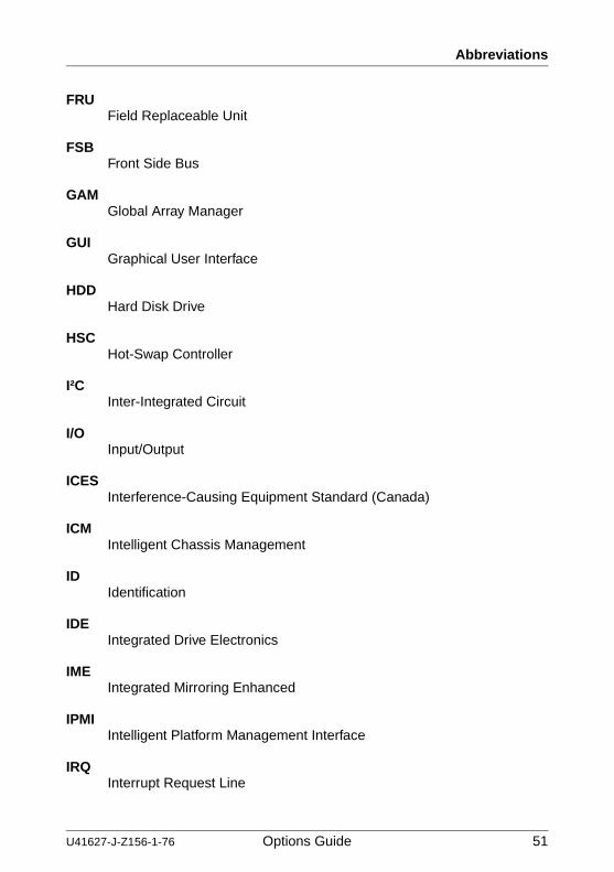
Abbreviations
FRUField Replaceable Unit
FSBFront Side Bus
GAMGlobal Array Manager
GUIGraphical User Interface
HDDHard Disk Drive
HSCHot-Swap Controller
I²CInter-Integrated Circuit
I/OInput/Output
ICESInterference-Causing Equipment Standard (Canada)
ICMIntelligent Chassis Management
IDIdentification
IDEIntegrated Drive Electronics
IMEIntegrated Mirroring Enhanced
IPMIIntelligent Platform Management Interface
IRQInterrupt Request Line
52 Options Guide U41627-J-Z156-1-76
Abbreviations
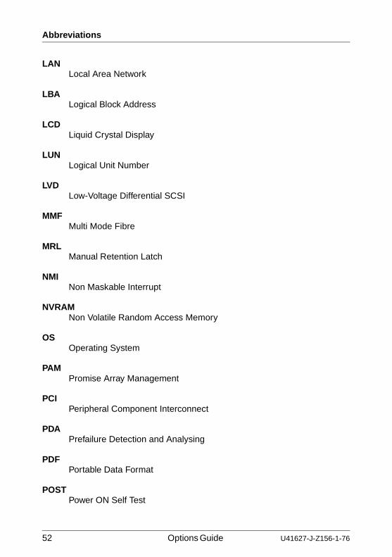
LANLocal Area Network
LBALogical Block Address
LCDLiquid Crystal Display
LUNLogical Unit Number
LVDLow-Voltage Differential SCSI
MMFMulti Mode Fibre
MRLManual Retention Latch
NMINon Maskable Interrupt
NVRAMNon Volatile Random Access Memory
OSOperating System
PAMPromise Array Management
PCIPeripheral Component Interconnect
PDAPrefailure Detection and Analysing
PDFPortable Data Format
POSTPower ON Self Test
U41627-J-Z156-1-76 Options Guide 53
Abbreviations
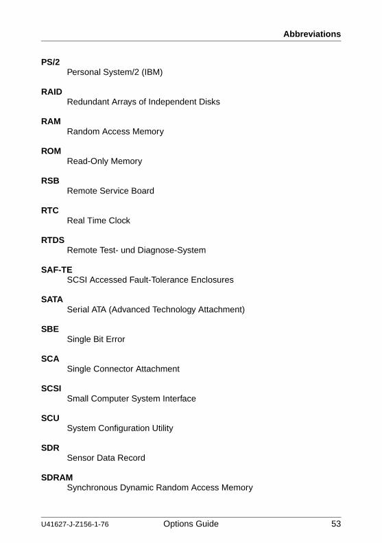
PS/2Personal System/2 (IBM)
RAIDRedundant Arrays of Independent Disks
RAMRandom Access Memory
ROMRead-Only Memory
RSBRemote Service Board
RTCReal Time Clock
RTDSRemote Test- und Diagnose-System
SAF-TESCSI Accessed Fault-Tolerance Enclosures
SATASerial ATA (Advanced Technology Attachment)
SBESingle Bit Error
SCASingle Connector Attachment
SCSISmall Computer System Interface
SCUSystem Configuration Utility
SDRSensor Data Record
SDRAMSynchronous Dynamic Random Access Memory
54 Options Guide U41627-J-Z156-1-76
Abbreviations
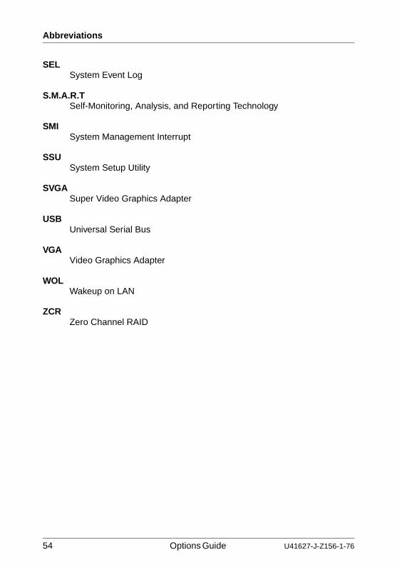
SELSystem Event Log
S.M.A.R.TSelf-Monitoring, Analysis, and Reporting Technology
SMISystem Management Interrupt
SSUSystem Setup Utility
SVGASuper Video Graphics Adapter
USBUniversal Serial Bus
VGAVideo Graphics Adapter
WOLWakeup on LAN
ZCRZero Channel RAID
U41627-J-Z156-1-76 Options Guide 55
Related publicationsPRIMERGY manuals are available as PDF files on the ServerBooks CD. The ServerBooks CD is part of the ServerView Suite delivered with each server system.
The current versions of the required manuals can be downloaded free of charge as PDF files from the Internet. The overview page showing the online documen-tation available on the Internet can be found via the URL: http://manuals.fujitsu-siemens.com. For the documentation of the PRIMERGY servers choose the navigation point industry standard servers.
[1] Safety
[2] Ergonomics
[3] Warranty
[4] Returning used devices
[5] System board D2179 for Econel 100 Technical Manual
[6] BIOS-Setup Reference Manual
[7] Quickstart Hardware - PRIMERGY Econel 100 Poster
[8] Quickstart Software - PRIMERGY ServerView Suite Poster
[9] PRIMERGY Econel 100 Server System Operating Manual
[10] PRIMERGY ServerView Suite ServerStartUser Manual
[11] LSI SATA Software RAID User Manual
56 Options Guide U41627-J-Z156-1-76
Related publications
[12] Configurator For partners and distributors only:http://extranet.fujitsu-siemens.com/cafe/products/primergy
U41627-J-Z156-1-76 Options Guide 57
IndexAaccessible drives 6, 25
Ccontroller 7
EEMC regulations 27, 30ESD (devices sensitive to electrostatic
discharge) 15ESD-sensitive devices 15
FFDD dummy 30front cover 18, 45
Hhard disk drives 33
Iinformation 6
Llight-emitting diode (LED) 15lithium battery 14
Mmain memory 6meaning
of the symbols 7
Nnotational conventions 7note about the laser 15
Ooverview cables 47
PPCI controller
low-profile 41standard 39
PCI slots 39power supply unit 19, 44
SSATA hard disk drive 6server
closing 46opening 17
slide-in unitaccessible drives 27
system fan 20, 43
Ttarget group 5

Comments on PRIMERGY Econel 100 Server System
U41627-J-Z156-1-76
Comments Suggestions Corrections
✁
Submitted by
Fujitsu Siemens Computers GmbH User Documentation 81730 Munich Germany
Fax: (++49) 700 / 372 00000
email: [email protected] http://manuals.fujitsu-siemens.com


Comments on PRIMERGY Econel 100 Server System
U41627-J-Z156-1-76
Comments Suggestions Corrections
✁
Submitted by
Fujitsu Siemens Computers GmbH User Documentation 81730 Munich Germany
Fax: (++49) 700 / 372 00000
email: [email protected] http://manuals.fujitsu-siemens.com


Information on this document On April 1, 2009, Fujitsu became the sole owner of Fujitsu Siemens Compu-ters. This new subsidiary of Fujitsu has been renamed Fujitsu Technology So-lutions.
This document from the document archive refers to a product version which was released a considerable time ago or which is no longer marketed.
Please note that all company references and copyrights in this document have been legally transferred to Fujitsu Technology Solutions.
Contact and support addresses will now be offered by Fujitsu Technology So-lutions and have the format …@ts.fujitsu.com.
The Internet pages of Fujitsu Technology Solutions are available at http://ts.fujitsu.com/... and the user documentation at http://manuals.ts.fujitsu.com.
Copyright Fujitsu Technology Solutions, 2009
Hinweise zum vorliegenden Dokument Zum 1. April 2009 ist Fujitsu Siemens Computers in den alleinigen Besitz von Fujitsu übergegangen. Diese neue Tochtergesellschaft von Fujitsu trägt seit-dem den Namen Fujitsu Technology Solutions.
Das vorliegende Dokument aus dem Dokumentenarchiv bezieht sich auf eine bereits vor längerer Zeit freigegebene oder nicht mehr im Vertrieb befindliche Produktversion.
Bitte beachten Sie, dass alle Firmenbezüge und Copyrights im vorliegenden Dokument rechtlich auf Fujitsu Technology Solutions übergegangen sind.
Kontakt- und Supportadressen werden nun von Fujitsu Technology Solutions angeboten und haben die Form …@ts.fujitsu.com.
Die Internetseiten von Fujitsu Technology Solutions finden Sie unter http://de.ts.fujitsu.com/..., und unter http://manuals.ts.fujitsu.com finden Sie die Benutzerdokumentation.
Copyright Fujitsu Technology Solutions, 2009