Embed Size (px)
Citation preview
Primergy
PRIMERGY SX30Storage Subsystem Operating ManualGünter BenkelbergFujitsu Siemens Computers GmbH Paderborn81730 Münchene-mail: Internet:[email protected].: 0 52 51 / 81 48 91Fax: (++49) 700 / 372 00000U41169-J-Z156-4-74Sprachen: En
Edition March 2006

Comments… Suggestions… Corrections…The User Documentation Department would like toknow your opinion of this manual. Your feedback helpsus optimize our documentation to suit your individual needs.
Fax forms for sending us your comments are included inthe back of the manual.
There you will also find the addresses of the relevantUser Documentation Department.
Certified documentation according to DIN EN ISO 9001:2000To ensure a consistently high quality standard anduser-friendliness, this documentation was created tomeet the regulations of a quality management system which complies with the requirements of the standardDIN EN ISO 9001:2000.
cognitas. Gesellschaft für Technik-Dokumentation mbHwww.cognitas.de
Copyright and Trademarks
Copyright © 2006 Fujitsu Siemens Computers GmbH.All rights reserved.Delivery subject to availability; right of technical modifications reserved.
All hardware and software names used are trademarks of their respective manufacturers.
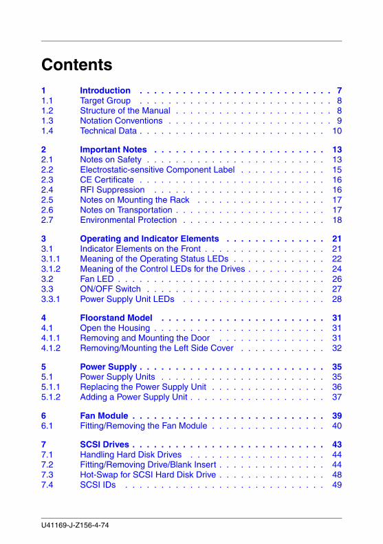
Contents1 Introduction . . . . . . . . . . . . . . . . . . . . . . . . . . . 71.1 Target Group . . . . . . . . . . . . . . . . . . . . . . . . . . . 81.2 Structure of the Manual . . . . . . . . . . . . . . . . . . . . . . 81.3 Notation Conventions . . . . . . . . . . . . . . . . . . . . . . . 91.4 Technical Data . . . . . . . . . . . . . . . . . . . . . . . . . . 10
2 Important Notes . . . . . . . . . . . . . . . . . . . . . . . . 132.1 Notes on Safety . . . . . . . . . . . . . . . . . . . . . . . . . 132.2 Electrostatic-sensitive Component Label . . . . . . . . . . . . 152.3 CE Certificate . . . . . . . . . . . . . . . . . . . . . . . . . . 162.4 RFI Suppression . . . . . . . . . . . . . . . . . . . . . . . . 162.5 Notes on Mounting the Rack . . . . . . . . . . . . . . . . . . 172.6 Notes on Transportation . . . . . . . . . . . . . . . . . . . . . 172.7 Environmental Protection . . . . . . . . . . . . . . . . . . . . 18
3 Operating and Indicator Elements . . . . . . . . . . . . . . 213.1 Indicator Elements on the Front . . . . . . . . . . . . . . . . . 213.1.1 Meaning of the Operating Status LEDs . . . . . . . . . . . . . 223.1.2 Meaning of the Control LEDs for the Drives . . . . . . . . . . . 243.2 Fan LED . . . . . . . . . . . . . . . . . . . . . . . . . . . . . 263.3 ON/OFF Switch . . . . . . . . . . . . . . . . . . . . . . . . . 273.3.1 Power Supply Unit LEDs . . . . . . . . . . . . . . . . . . . . 28
4 Floorstand Model . . . . . . . . . . . . . . . . . . . . . . . 314.1 Open the Housing . . . . . . . . . . . . . . . . . . . . . . . . 314.1.1 Removing and Mounting the Door . . . . . . . . . . . . . . . 314.1.2 Removing/Mounting the Left Side Cover . . . . . . . . . . . . 32
5 Power Supply . . . . . . . . . . . . . . . . . . . . . . . . . . 355.1 Power Supply Units . . . . . . . . . . . . . . . . . . . . . . . 355.1.1 Replacing the Power Supply Unit . . . . . . . . . . . . . . . . 365.1.2 Adding a Power Supply Unit . . . . . . . . . . . . . . . . . . . 37
6 Fan Module . . . . . . . . . . . . . . . . . . . . . . . . . . . 396.1 Fitting/Removing the Fan Module . . . . . . . . . . . . . . . . 40
7 SCSI Drives . . . . . . . . . . . . . . . . . . . . . . . . . . . 437.1 Handling Hard Disk Drives . . . . . . . . . . . . . . . . . . . 447.2 Fitting/Removing Drive/Blank Insert . . . . . . . . . . . . . . . 447.3 Hot-Swap for SCSI Hard Disk Drive . . . . . . . . . . . . . . . 487.4 SCSI IDs . . . . . . . . . . . . . . . . . . . . . . . . . . . . 49
U41169-J-Z156-4-74
Contents
8 Electronic Modules . . . . . . . . . . . . . . . . . . . . . . 518.1 Single Node SCSI Module . . . . . . . . . . . . . . . . . . . 518.1.1 Single Node SCSI Module One-channel . . . . . . . . . . . . 518.1.2 Single Node SCSI Module Two-channel . . . . . . . . . . . . 538.2 Dual Node SCSI Module . . . . . . . . . . . . . . . . . . . . 558.2.1 Dual Node SCSI Module Two-channels . . . . . . . . . . . . . 558.3 Fitting/Removing a Module . . . . . . . . . . . . . . . . . . . 57
9 Connections . . . . . . . . . . . . . . . . . . . . . . . . . . 599.1 Connections for the One-channel Configuration . . . . . . . . 599.2 Connections for the Two-channel Configurations . . . . . . . . 609.3 SCSI Connection . . . . . . . . . . . . . . . . . . . . . . . . 619.4 Mains Connection . . . . . . . . . . . . . . . . . . . . . . . . 639.5 Mains Connection with Phase Redundancy . . . . . . . . . . . 64
10 Configurations . . . . . . . . . . . . . . . . . . . . . . . . . 6510.1 With Single Node SCSI Modules (One-channels) . . . . . . . . 6510.2 With Single Node SCSI Modules (Two-channels) . . . . . . . . 6610.3 With Dual Node SCSI Modules (Two-channel) . . . . . . . . . 67
11 Installation . . . . . . . . . . . . . . . . . . . . . . . . . . . 6911.1 Installation Steps . . . . . . . . . . . . . . . . . . . . . . . . 6911.2 Unpacking the Storage Subsystem . . . . . . . . . . . . . . . 7011.3 Setting Up the Floorstand Model . . . . . . . . . . . . . . . . 7011.4 Installing and Uninstalling the Storage Subsystem in and from the
Rack . . . . . . . . . . . . . . . . . . . . . . . . . . . . . . . 7111.5 Requirements of the Rack . . . . . . . . . . . . . . . . . . . . 7111.6 Installing in the PRIMECENTER Rack . . . . . . . . . . . . . 7511.7 Installing in the DataCenter Rack . . . . . . . . . . . . . . . . 7811.8 Installing in the Classic Rack . . . . . . . . . . . . . . . . . . 7811.9 Installing in 3rd-Party Racks . . . . . . . . . . . . . . . . . . 7811.10 Installing the Server . . . . . . . . . . . . . . . . . . . . . . . 7911.11 Routing the Leads . . . . . . . . . . . . . . . . . . . . . . . . 8011.12 Connecting and Disconnecting Leads . . . . . . . . . . . . . . 8211.13 Switching the Storage Subsystem ON/OFF . . . . . . . . . . . 83
12 Fault Clearing . . . . . . . . . . . . . . . . . . . . . . . . . 8512.1 Problem Solutions and Tips . . . . . . . . . . . . . . . . . . . 8612.1.1 Power Supply Indication (Front) . . . . . . . . . . . . . . . . . 8612.1.1.1 Power supply indication remains dark . . . . . . . . . . . . . . 8612.1.1.2 Power supply indication is yellow . . . . . . . . . . . . . . . . 8612.1.1.3 Power supply indication is flashing orange . . . . . . . . . . . 8712.1.2 Cooling Status . . . . . . . . . . . . . . . . . . . . . . . . . . 8712.1.2.1 Cooling status LED is yellow . . . . . . . . . . . . . . . . . . 87
U41169-J-Z156-4-74
Contents
12.1.2.2 Cooling status LED is orange . . . . . . . . . . . . . . . . . . 8812.1.3 Server Management Status . . . . . . . . . . . . . . . . . . . 8812.1.4 Storage Subsystem Switches OFF . . . . . . . . . . . . . . . 8912.1.5 System does not Start Up after New Drives have been Installed 8912.1.6 Hard Disk Drive Operating Indication does not Come ON . . . 8912.1.7 Drives “dead” on System Start . . . . . . . . . . . . . . . . . 8912.1.8 RAID Controller Indicates the Added Drive to be Incorrect . . . 9012.1.9 Storage Subsystem cannot be Switched OFF by the Server . . 90
Abbreviations . . . . . . . . . . . . . . . . . . . . . . . . . . . . . . . 91
Related publications . . . . . . . . . . . . . . . . . . . . . . . . . . . 93
Index . . . . . . . . . . . . . . . . . . . . . . . . . . . . . . . . . . . . 95
U41169-J-Z156-4-74

1 IntroductionThe functionality, mechanics and design of the PRIMERGY SX30 storage subsystem are optimally adapted to the PRIMERGY servers. It can be used as rack or floorstand model. In the 19-inch rack, the SX30 subsystem occupies three height units.
The PRIMERGY SX30 storage subsystem can accommodate up to fourteen 1-inch hard disk drives. If it is equipped, e. g. with 146 Gbyte Ultra 160/320 SCSI drives, approximately 2 Tbyte hard disk memory is available as a maximum within one housing.
The PRIMERGY SX30 exists in a single-node, as well as in a dual-node version. Whereas the one-channel option (1 x 14 HDD) and the two-channel option (2 x 7 HDD) are both available for the single-node version, there is only the two-channel option for the dual-node (cluster) version.
The cluster capability is made possible by the use of dual node SCSI modules. In conjunction with the Microsoft Windows 2000 Advanced Server, two PRIMERGY servers can be run over two channels on a two-channel PRIMERGY SX30 storage subsystem via one RAID controller each. As a result of the dual node SCSI module, both servers are connected to each SCSI channel in the storage subsystem.
Server Management/ServerView
ServerView uses the SAF-TE protocol of the SCSI bus to communicate with the clients.
ServerView and the related agents are set up within the group of servers and storage subsystems being monitored. The received informations are evaluated by ServerView and processed for display or forwarding to the administrator (manager).
I When installing PRIMERGY SX30 Storage Subsystems in connection with ServerView please install the ServerStart CD version 3.29 or higher on each of the connected servers.
Notes to installing and update see at the documentation of ServerView (see also “Related publications” on page 93).
U41169-J-Z156-4-74 7
Target Group Introduction
1.1 Target Group
The operating instructions are intended for the person responsible for installing the hardware and correctly operating the system. The operating instructions contain all the descriptions which are of importance for commissioning your PRIMERGY SX30 storage subsystem in so far as they do not form part of the publication of your server system.
To understand the different expansion options it is necessary to have a knowledge of hardware and data transmission, as well as basic knowledge of the operating system used.
1.2 Structure of the Manual
The PRIMERGY SX30 storage subsystem manual describes how to install and configure the subsystem and perform expansions or upgrades.
You will find further information (see also entries in the chapter “Related publi-cations” on page 93):
● in the “Safety and Ergonomics” manual
● in the documentation on the PRIMERGY server
This manual consists of the following chapters:
● Important notesThis chapter contains instructions on the safe operation of your storage subsystem as well as information about environmental protection.
● Operating and indicator elementsThis chapter gives a detailed description of the operating panel and the connecting elements on the rear panel of the corresponding storage subsystem.
● Floorstand modelThis part of the manual describes how opening and closing the floorstand model housing.
● Power supplyThis part of the manual describes the power supply units and their power supply. Fitting and removing power supply units is also described in detail.
● Fan moduleThis part of the manual describes the fitting and removal of the fan module.
8 U41169-J-Z156-4-74
Introduction Notation Conventions
● SCSI drivesThis chapter describes in detail how the hot replacement drives must be dealt with.
● Electronic modulesThis chapter describes the SCSI modules and its fitting and removal.
● Connections This chapter describes the SCSI and the mains connection.
The possibilities of supplying the storage subsystem with mains voltage are also described.
● ConfigurationsThis part of the manual gives SCSI configuration examples.
● InstallationThe activities needed to install and commission the storage subsystem are described.
● Clearing faultsThis chapter contains advice on solving problems that occur on commis-sioning or during the operation of the storage subsystem.
1.3 Notation Conventions
Italics identifies commands and entries in flow text
Semibold highlights text
“Quotation marks” indicates references to other chapters or manuals
Ê identifies an operation that you have to perform.
I indicates additional information, notes and tips
V CAUTION! indicates warnings, which, if ignored, will endanger your health, the operability of your server or the security of your data
Table 1: Notation Conventions
U41169-J-Z156-4-74 9
Technical Data Introduction
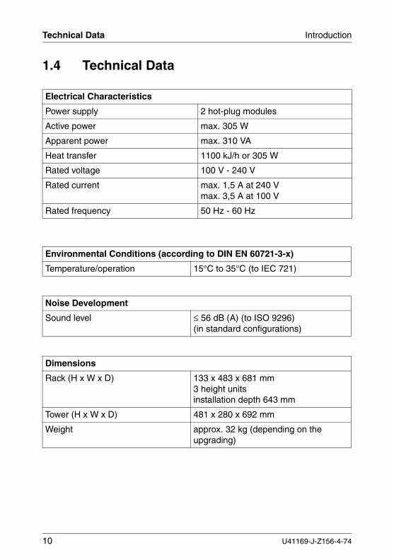
1.4 Technical Data
Electrical Characteristics
Power supply 2 hot-plug modules
Active power max. 305 W
Apparent power max. 310 VA
Heat transfer 1100 kJ/h or 305 W
Rated voltage 100 V - 240 V
Rated current max. 1,5 A at 240 Vmax. 3,5 A at 100 V
Rated frequency 50 Hz - 60 Hz
Environmental Conditions (according to DIN EN 60721-3-x)
Temperature/operation 15°C to 35°C (to IEC 721)
Noise Development
Sound level ≤ 56 dB (A) (to ISO 9296)(in standard configurations)
Dimensions
Rack (H x W x D) 133 x 483 x 681 mm3 height unitsinstallation depth 643 mm
Tower (H x W x D) 481 x 280 x 692 mm
Weight approx. 32 kg (depending on the upgrading)
10 U41169-J-Z156-4-74
Introduction Technical Data
Standards Complied With
Product safety
Global IEC 60950
Europe EN 60950
USA / Canada UL 1950, CSA 22.2 No. 950
Electromagnetic compatibility
Europe EN 55022, Class A,EN 55024, EN 61000-3-3
Taiwan -
Japan -
Australia / New Zealand -
USA / Canada FCC Class A
Method of conformity
Europe (CE) 73/23/EWG (EMV)
North America FCC Class A
Admittance
Product safety
Global CB
Europe ENEC
Germany GS
USA / Canada CSAUS / CSAC
U41169-J-Z156-4-74 11

2 Important Notes
2.1 Notes on Safety
In this section you will find information that you must note when using the storage subsystem.
This device complies with the relevant safety standards for IT equipment, including electronic office machines, intended for use in the office environment.
I You will also find the following safety instructions in the manual entitled “Safety, Guarantee and Ergonomics“ which also includes other notes on guarantee and ergonomics. Also pay attention to the notes in the manual of the connected PRIMERGY system.
If you have any questions relating to setting up and operating your system in the environment where you intend to use it, please consult our service organization.
V CAUTION!
● The actions described in these instructions should only be performed by technicians, service personnel or technical specialists. Equipment repairs should only be performed by qualified staff. Any failure to observe the guidelines in this manual could expose the user to considerable risks (electric shock, fire hazards) and could also damage the equipment. Note that any unauthorized opening of the device will result in the invalidation of the warranty and exclusion from all liability.
● Transport the device in its original packaging or in other suitable packaging which will protect it against shock or impact.
● Read the notes on environmental conditions in section “Technical Data” on page 10 before setting up and operating the device.
● If the device is brought in from a cold environment, condensation may form both inside and on the outside of the machine.
Wait until the device has acclimatized to room temperature and is absolutely dry before starting it up. Material damage may be caused to the device if this requirement is not observed.
U41169-J-Z156-4-74 13
Notes on Safety Important Notes
V CAUTION!
● Check that the rated voltage specified on the device's ID plate is the same as the local line voltage.
● The device must only be connected to a properly grounded wall outlet (the device is fitted with a tested and approved power cable).
● Make sure that the protective grounded outlet of the building’s wiring system is freely accessible.
● Switching off the device does not cut off the supply of power. To do this you must remove the power plugs.
● Before opening the unit, switch off the device and then pull out the power plugs.
● Route the cables in such a way that they do not form a potential hazard (make sure no-one can trip over them) and that they cannot be damaged. When connecting up a device, refer to the relevant notes in this manual.
● Never connect or disconnect data transmission lines during a storm (lightning hazard).
● Systems which comprise a number of cabinets must use a separate fused socket for each cabinet.
● The system unit and the directly connected external storage subsystems should be connected to the same power supply distributor. Otherwise you run the risk of losing data if, for example, the central processing unit is still running but the storage subsystem has failed during a power failure.
● Make sure that no objects (such as bracelets or paper clips) fall into or liquids spill into the device (risk of electric shock or short circuit).
● In emergencies (e.g. damage to housings, power cords or controls or ingress of liquids or foreign bodies), immediately power down the device, pull out the power plugs and notify your service department.
● Note that proper operation of the system (in accordance with IEC 60950/DIN EN 60950) is guaranteed only if slot covers are installed on all vacant slots and/or dummies on all vacant bays and the housing cover is fitted (cooling, fire protection, RFI suppression).
14 U41169-J-Z156-4-74
Important Notes Electrostatic-sensitive Component Label
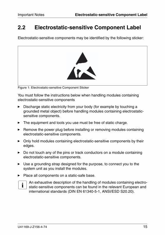
2.2 Electrostatic-sensitive Component Label
Electrostatic-sensitive components may be identified by the following sticker:
Figure 1: Electrostatic-sensitive Component Sticker
You must follow the instructions below when handling modules containing electrostatic-sensitive components
Ê Discharge static electricity from your body (for example by touching a grounded metal object) before handling modules containing electrostatic-sensitive components.
Ê The equipment and tools you use must be free of static charge.
Ê Remove the power plug before installing or removing modules containing electrostatic-sensitive components.
Ê Only hold modules containing electrostatic-sensitive components by their edges.
Ê Do not touch any of the pins or track conductors on a module containingelectrostatic-sensitive components.
Ê Use a grounding strap designed for the purpose, to connect you to the system unit as you install the modules.
Ê Place all components on a static-safe base.
I An exhaustive description of the handling of modules containing electro-static-sensitive components can be found in the relevant European and international standards (DIN EN 61340-5-1, ANSI/ESD S20.20).
U41169-J-Z156-4-74 15
CE Certificate Important Notes
2.3 CE Certificate
2.4 RFI Suppression
All other equipment which is connected to this product must also have radio noise suppression in accordance with EC Guideline 89/336/EWG.
Products which meet this requirement are accompanied by a certificate to that effect issued by the manufacturer and/or bear the CE mark. Products which do not meet this requirement may be operated only with the special permission of the BZT (Bundesamt für Zulassungen in der Telekommunikation).
I This is a “Class A“ equipment. This equipment may cause harmful inter-ference in residential areas. In this case, the user may be held liable for taking appropriate measures and bearing the costs resulting from these measures.
The shipped version of this device complies with the requirements of the EEC directives 89/336/EEC ”Electromagnetic compatibility“ and 73/23/EEC ”Low voltage directive“. The device therefore qualifies for the CE certificate (CE=Communauté Européenne).
16 U41169-J-Z156-4-74
Important Notes Notes on Mounting the Rack
2.5 Notes on Mounting the Rack
● For safety reasons, at least two people are required to install the rack-mounted model because of its weight and size.
● When connecting and disconnecting cables, observe the notes in the documentation for your PRIMERGY system and the comments in the ”Important notes“ chapter in the 19-inch rack operating manual supplied with the rack.
● Ensure that the anti-tilt bracket is correctly mounted when you set up the rack.
● For safety reasons, no more than one unit may be withdrawn from the rack at any one time during installation and maintenance work.
● If more than one unit is withdrawn from the rack at any one time, there is a danger that the rack will tilt forward.
● The power supply to the rack must be installed by an authorized specialist (electrician).
2.6 Notes on Transportation
I Transport the storage subsystem in its original packaging or in other suitable packaging which will protect it against shock or impact.Do not unpack it until all transport maneuvers are completed.
If you need to lift or transport the storage subsystem, ask someone to help you.
U41169-J-Z156-4-74 17

Environmental Protection Important Notes
2.7 Environmental Protection
Environmentally friendly product design and development
This product has been designed in accordance with the FSC standard for “environmentally friendly product design and development”.
This means that the designers have taken into account important criteria such as durability, selection of materials and coding, emissions, packaging, the ease with which the product can be dismantled and the extent to which it can be recycled.
This saves resources and thus reduces the harm done to the environment.
Notes on saving energy
Devices that do not have to be on permanently should not be switched on until they need to be used and should be switched off during long breaks and on completion of work
Notes on packaging
We recommend that you do not throw away the original packaging in case you need it later for transportation. If possible, devices should be transported in their original packaging.
Notes on labeling plastic housing parts
Please avoid attaching your own labels to plastic housing parts wherever possible, since this makes it difficult to recycle them.
Take-back, recycling and disposal
For details on take-back and reuse of devices and consumables within Europe, contact your FSC branch office/subsidiary or our recycling center in Paderborn:
Fujitsu Siemens ComputersRecycling CenterD-33106 Paderborn
Tel. ++49 5251 8180-10
Fax ++49 5251 8180-15
18 U41169-J-Z156-4-74

Important Notes Environmental Protection
Further information on environmental protection
The Fujitsu Siemens Computers representative for environmental protection will be happy to answer any further questions you may have concerning environ-mental protection.
Fujitsu Siemens ComputersReferat UmweltschutzWerner-von-Siemens-Straße 6D-86159 Augsburg
Tel. ++49 821 804-2386
Fax ++49 821 804-2706
U41169-J-Z156-4-74 19

3 Operating and Indicator ElementsThis section describes the position and meaning of the operating and indicator elements on the PRIMERGY SX30 storage subsystem.
3.1 Indicator Elements on the Front
You can see the following on the front of the PRIMERGY SX30 subsystem
● The three operating status LEDs which indicate the power supply status, the cooling status and the server management status.
● Control LEDs for the drives.
I There is a busy and a fault LED for each of the 14 possible hard disk drives.
U41169-J-Z156-4-74 21
Indicator Elements on the Front Operating and Indicator Elements
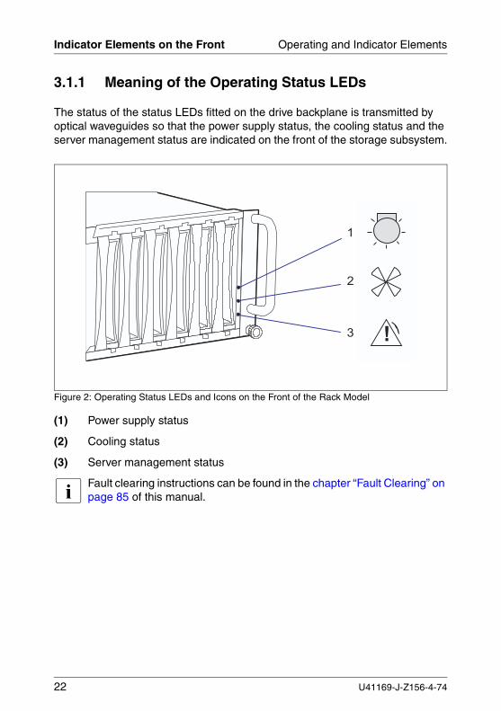
3.1.1 Meaning of the Operating Status LEDs
The status of the status LEDs fitted on the drive backplane is transmitted by optical waveguides so that the power supply status, the cooling status and the server management status are indicated on the front of the storage subsystem.
Figure 2: Operating Status LEDs and Icons on the Front of the Rack Model
(1) Power supply status
(2) Cooling status
(3) Server management status
I Fault clearing instructions can be found in the chapter “Fault Clearing” on page 85 of this manual.
��
�
�
22 U41169-J-Z156-4-74
Operating and Indicator Elements Indicator Elements on the Front
V CAUTION!
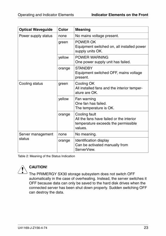
The PRIMERGY SX30 storage subsystem does not switch OFF automatically in the case of overheating. Instead, the server switches it OFF because data can only be saved to the hard disk drives when the connected server has been shut down properly. Sudden switching OFF can destroy the data.
Optical Waveguide Color Meaning
Power supply status none No mains voltage present.
green POWER OKEquipment switched on, all installed power supply units OK.
yellow POWER WARNINGOne power supply unit has failed.
orange STANDBY Equipment switched OFF, mains voltage present.
Cooling status green Cooling OKAll installed fans and the interior temper-ature are OK.
yellow Fan warningOne fan has failed.The temperature is OK.
orange Cooling faultAll the fans have failed or the interior temperature exceeds the permissible values.
Server management status
none No meaning.
orange Identification displayCan be activated manually from ServerView.
Table 2: Meaning of the Status Indication
U41169-J-Z156-4-74 23
Indicator Elements on the Front Operating and Indicator Elements
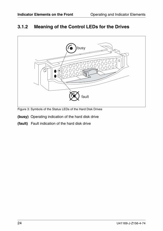
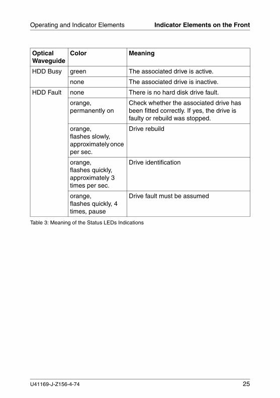
3.1.2 Meaning of the Control LEDs for the Drives
Figure 3: Symbols of the Status LEDs of the Hard Disk Drives
(busy) Operating indication of the hard disk drive
(fault) Fault indication of the hard disk drive
� � � �
� � �
24 U41169-J-Z156-4-74
Operating and Indicator Elements Indicator Elements on the Front
Optical Waveguide
Color Meaning
HDD Busy green The associated drive is active.
none The associated drive is inactive.
HDD Fault none There is no hard disk drive fault.
orange,permanently on
Check whether the associated drive has been fitted correctly. If yes, the drive is faulty or rebuild was stopped.
orange,flashes slowly, approximately once per sec.
Drive rebuild
orange,flashes quickly, approximately 3 times per sec.
Drive identification
orange,flashes quickly, 4 times, pause
Drive fault must be assumed
Table 3: Meaning of the Status LEDs Indications
U41169-J-Z156-4-74 25
Fan LED Operating and Indicator Elements
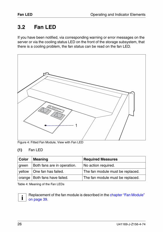
3.2 Fan LED
If you have been notified, via corresponding warning or error messages on the server or via the cooling status LED on the front of the storage subsystem, that there is a cooling problem, the fan status can be read on the fan LED.
Figure 4: Fitted Fan Module, View with Fan LED
(1) Fan LED
I Replacement of the fan module is described in the chapter “Fan Module” on page 39.
Color Meaning Required Measures
green Both fans are in operation. No action required.
yellow One fan has failed. The fan module must be replaced.
orange Both fans have failed. The fan module must be replaced.
Table 4: Meaning of the Fan LEDs
�
26 U41169-J-Z156-4-74
Operating and Indicator Elements ON/OFF Switch
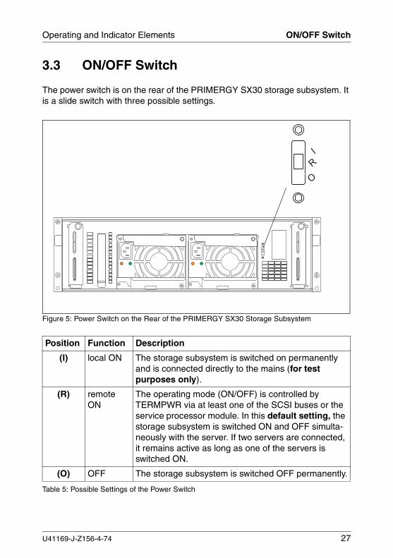
3.3 ON/OFF Switch
The power switch is on the rear of the PRIMERGY SX30 storage subsystem. It is a slide switch with three possible settings.
Figure 5: Power Switch on the Rear of the PRIMERGY SX30 Storage Subsystem
Position Function Description
(I) local ON The storage subsystem is switched on permanently and is connected directly to the mains (for test purposes only).
(R) remote ON
The operating mode (ON/OFF) is controlled by TERMPWR via at least one of the SCSI buses or the service processor module. In this default setting, the storage subsystem is switched ON and OFF simulta-neously with the server. If two servers are connected, it remains active as long as one of the servers is switched ON.
(O) OFF The storage subsystem is switched OFF permanently.
Table 5: Possible Settings of the Power Switch
�
��
U41169-J-Z156-4-74 27
ON/OFF Switch Operating and Indicator Elements
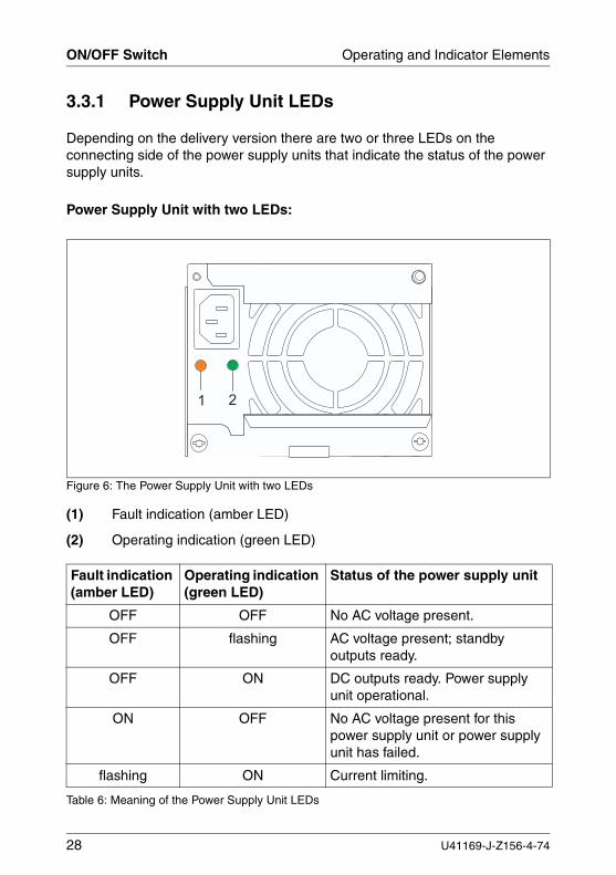
3.3.1 Power Supply Unit LEDs
Depending on the delivery version there are two or three LEDs on the connecting side of the power supply units that indicate the status of the power supply units.
Power Supply Unit with two LEDs:
Figure 6: The Power Supply Unit with two LEDs
(1) Fault indication (amber LED)
(2) Operating indication (green LED)
Fault indication (amber LED)
Operating indication (green LED)
Status of the power supply unit
OFF OFF No AC voltage present.
OFF flashing AC voltage present; standby outputs ready.
OFF ON DC outputs ready. Power supply unit operational.
ON OFF No AC voltage present for this power supply unit or power supply unit has failed.
flashing ON Current limiting.
Table 6: Meaning of the Power Supply Unit LEDs
� �
28 U41169-J-Z156-4-74
Operating and Indicator Elements ON/OFF Switch
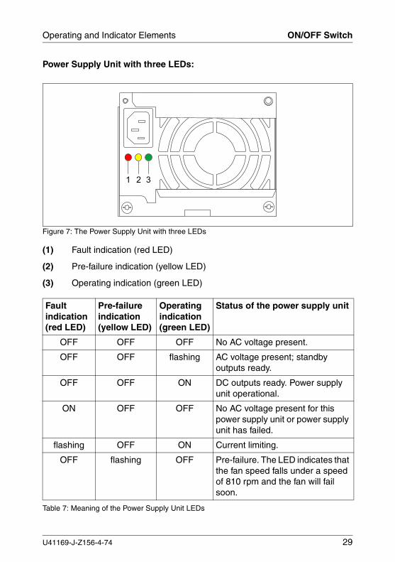
Power Supply Unit with three LEDs:
Figure 7: The Power Supply Unit with three LEDs
(1) Fault indication (red LED)
(2) Pre-failure indication (yellow LED)
(3) Operating indication (green LED)
Fault indication (red LED)
Pre-failure indication (yellow LED)
Operating indication (green LED)
Status of the power supply unit
OFF OFF OFF No AC voltage present.
OFF OFF flashing AC voltage present; standby outputs ready.
OFF OFF ON DC outputs ready. Power supply unit operational.
ON OFF OFF No AC voltage present for this power supply unit or power supply unit has failed.
flashing OFF ON Current limiting.
OFF flashing OFF Pre-failure. The LED indicates that the fan speed falls under a speed of 810 rpm and the fan will fail soon.
Table 7: Meaning of the Power Supply Unit LEDs
1 2 3
U41169-J-Z156-4-74 29

4 Floorstand Model
4.1 Open the Housing
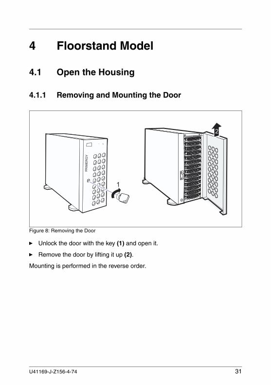
4.1.1 Removing and Mounting the Door
Figure 8: Removing the Door
Ê Unlock the door with the key (1) and open it.
Ê Remove the door by lifting it up (2).
Mounting is performed in the reverse order.
�
�
�
U41169-J-Z156-4-74 31
Open the Housing Floorstand Model
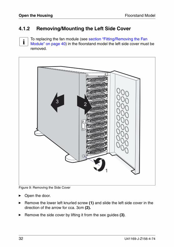
4.1.2 Removing/Mounting the Left Side Cover
I To replacing the fan module (see section “Fitting/Removing the Fan Module” on page 40) in the floorstand model the left side cover must be removed.
Figure 9: Removing the Side Cover
Ê Open the door.
Ê Remove the lower left knurled screw (1) and slide the left side cover in the direction of the arrow for cca. 3cm (2).
Ê Remove the side cover by lifting it from the sex guides (3).
�
�
�
32 U41169-J-Z156-4-74
Floorstand Model Open the Housing
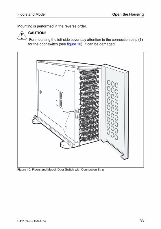
Mounting is performed in the reverse order.
V CAUTION!
For mounting the left side cover pay attention to the connection strip (1) for the door switch (see figure 10). It can be damaged.
Figure 10: Floorstand Model: Door Switch with Connection Strip
�
U41169-J-Z156-4-74 33

5 Power Supply
5.1 Power Supply Units
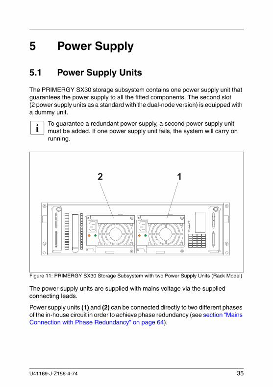
The PRIMERGY SX30 storage subsystem contains one power supply unit that guarantees the power supply to all the fitted components. The second slot (2 power supply units as a standard with the dual-node version) is equipped with a dummy unit.
I To guarantee a redundant power supply, a second power supply unit must be added. If one power supply unit fails, the system will carry on running.
Figure 11: PRIMERGY SX30 Storage Subsystem with two Power Supply Units (Rack Model)
The power supply units are supplied with mains voltage via the supplied connecting leads.
Power supply units (1) and (2) can be connected directly to two different phases of the in-house circuit in order to achieve phase redundancy (see section “Mains Connection with Phase Redundancy” on page 64).
� �� �
U41169-J-Z156-4-74 35
Power Supply Units Power Supply
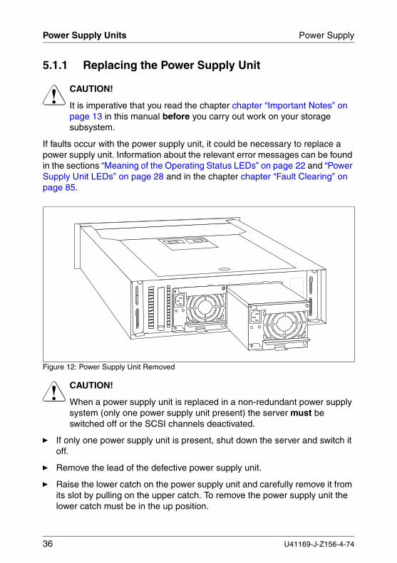
5.1.1 Replacing the Power Supply Unit
V CAUTION!
It is imperative that you read the chapter chapter “Important Notes” on page 13 in this manual before you carry out work on your storage subsystem.
If faults occur with the power supply unit, it could be necessary to replace a power supply unit. Information about the relevant error messages can be found in the sections “Meaning of the Operating Status LEDs” on page 22 and “Power Supply Unit LEDs” on page 28 and in the chapter chapter “Fault Clearing” on page 85.
Figure 12: Power Supply Unit Removed
V CAUTION!
When a power supply unit is replaced in a non-redundant power supply system (only one power supply unit present) the server must be switched off or the SCSI channels deactivated.
Ê If only one power supply unit is present, shut down the server and switch it off.
Ê Remove the lead of the defective power supply unit.
Ê Raise the lower catch on the power supply unit and carefully remove it from its slot by pulling on the upper catch. To remove the power supply unit the lower catch must be in the up position.
36 U41169-J-Z156-4-74
Power Supply Power Supply Units
Fitting is the reverse of removal:
Ê Push the new power supply unit into the empty slot (see next section “Adding a Power Supply Unit”).
V CAUTION!
Please ensure that the power supply unit engages correctly in the mounting frame and is locked in position. This is the only way to avoid the power supply unit being shaken out of its mountings and damaged during transport.
Ê Connect the lead to the power supply unit (see the section “Mains Connection” on page 63
Ê Connect the power cable to the mains (see section “Mains Connection” on page 63).
5.1.2 Adding a Power Supply Unit
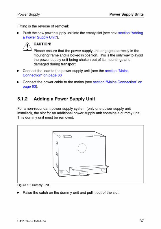
For a non-redundant power supply system (only one power supply unit installed), the slot for an additional power supply unit contains a dummy unit. This dummy unit must be removed.
Figure 13: Dummy Unit
Ê Raise the catch on the dummy unit and pull it out of the slot.
U41169-J-Z156-4-74 37
Power Supply Units Power Supply
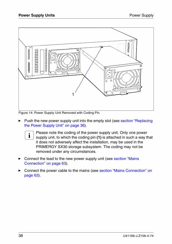
Figure 14: Power Supply Unit Removed with Coding Pin
Ê Push the new power supply unit into the empty slot (see section “Replacing the Power Supply Unit” on page 36).
I Please note the coding of the power supply unit. Only one power supply unit, to which the coding pin (1) is attached in such a way that it does not adversely affect the installation, may be used in the PRIMERGY SX30 storage subsystem. The coding may not be removed under any circumstances.
Ê Connect the lead to the new power supply unit (see section “Mains Connection” on page 63).
Ê Connect the power cable to the mains (see section “Mains Connection” on page 63).
�
38 U41169-J-Z156-4-74
6 Fan ModuleThe redundant fan module ensures cooling of the PRIMERGY SX30 storage subsystem. It is equipped with two fans. If one fails, the other working fan suffi-ciently guarantees cooling and prevents the components of the storage subsystem from overheating.
A temperature sensor on the rear panel of the power supply unit and a revolution monitor fitted for each fan are used to permanently check the cooling. Error messages can be read on the cooling status LED on the front panel of the storage subsystem (see section “Meaning of the Operating Status LEDs” on page 22) and on the fan LED (see section “Fan LED” on page 26).
As soon as fan failure is detected, the fan module with the defective fan should immediately be replaced with an intact module so that the redundancy charac-teristics (availability) are retained.
I Only the complete fan module may be replaced.
I The fan module can be replaced during operation.
V CAUTION!
The fan module should be replaced within 30 seconds to prevent possible overheating.
U41169-J-Z156-4-74 39
Fitting/Removing the Fan Module Fan Module
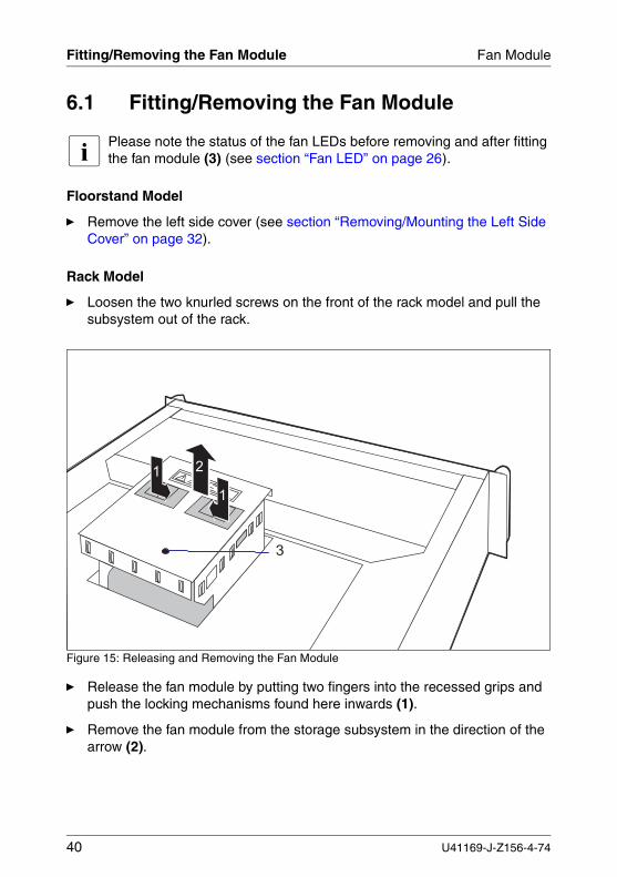
6.1 Fitting/Removing the Fan Module
I Please note the status of the fan LEDs before removing and after fitting the fan module (3) (see section “Fan LED” on page 26).
Floorstand Model
Ê Remove the left side cover (see section “Removing/Mounting the Left Side Cover” on page 32).
Rack Model
Ê Loosen the two knurled screws on the front of the rack model and pull the subsystem out of the rack.
Figure 15: Releasing and Removing the Fan Module
Ê Release the fan module by putting two fingers into the recessed grips and push the locking mechanisms found here inwards (1).
Ê Remove the fan module from the storage subsystem in the direction of the arrow (2).
�
�
�
�
40 U41169-J-Z156-4-74
U
Fan Module Fitting/Removing the Fan Module
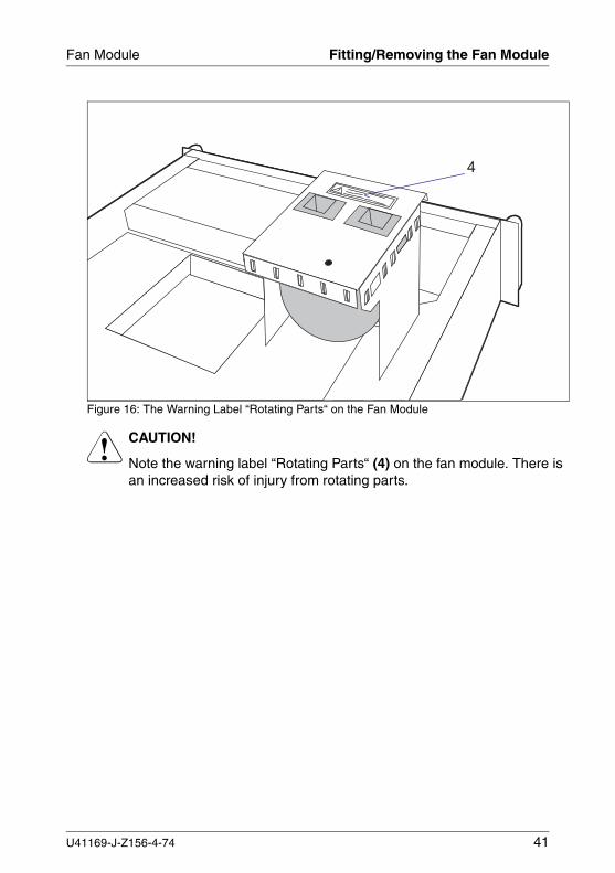
Figure 16: The Warning Label “Rotating Parts“ on the Fan Module
V CAUTION!
Note the warning label “Rotating Parts“ (4) on the fan module. There is an increased risk of injury from rotating parts.
�
41169-J-Z156-4-74 41
Fitting/Removing the Fan Module Fan Module
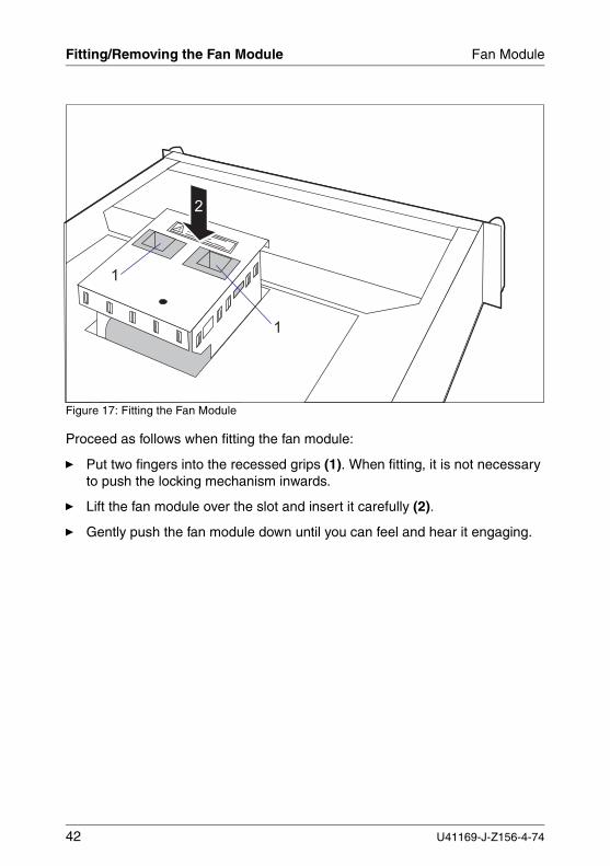
Figure 17: Fitting the Fan Module
Proceed as follows when fitting the fan module:
Ê Put two fingers into the recessed grips (1). When fitting, it is not necessary to push the locking mechanism inwards.
Ê Lift the fan module over the slot and insert it carefully (2).
Ê Gently push the fan module down until you can feel and hear it engaging.
�
�
�
42 U41169-J-Z156-4-74
7 SCSI DrivesThe PRIMERGY SX30 storage subsystem can accomodate up to fourteen 1-inch hard disk drives. If it is equipped, e. g. with 146 Gbyte Ultra 160/320 SCSI drives, approximately 2 Tbyte hard disk memory is available as a maximum within one housing.
With the one-channel option, all of the fourteen U320 SCSI hard disk drives are assigned only to this channel, and are accessible via a single node SCSI module.
With the two-channel option, seven U160/320 SCSI hard disk drives at a time are assigned to each of the two independend SCSI channels, and are acces-sible via two single-node SCSI modules in each case, as well as via the dual node SCSI module.
The SCSI hard disk drives are built into a frame which allows defective drives to be replaced (hot replacement) or new drives to be added (hot adding) during operation.
The “Hot Replace“ function can only be performed together with a corre-sponding RAID configuration. Further information about the RAID configuration or RAID level can be found in the disk array controller documentation.
A drive may only be replaced if it is inactive (see description of the LEDs in the table “Meaning of the Status LEDs Indications” on page 25) or has been marked as defective in the management tool.
The hot replacement procedure increases the availability of the system operation and guarantees a high degree of data integrity and protection against failure.
U41169-J-Z156-4-74 43
Handling Hard Disk Drives SCSI Drives
7.1 Handling Hard Disk Drives
Hard disk drives are highly sensitive electromagnetic devices and must be handled with great care. It is extremely likely that an incorrect handling will lead to a partially and/or total failure of the hard disk drives.
These failures will result in data errors and to loss of data or to total destruction of the hard disk drive.
Please observe following rules, which will help to avoid the occurrence of this type of problems:
● Store and transport hard disk units only within the limits stipulated in the specification.
● When transporting hard disk units (even over short distances), always use the original packaging (ESD labeling).
● Never expose a hard disk unit to a temperature shock. Avoid the formation of condensation inside and on the outside of the hard disk drives.
The hard disk drives may be exposed only to defined temperature and climatic conditions.
● Always put the hard disk unit down carefully, with its largest surface facing downwards, to avoid the danger of tipping over.
7.2 Fitting/Removing Drive/Blank Insert
V CAUTION!
Under no circumstances should you remove a hard disk unit while the system is in operation if you are not sure that the hard disk drive is operated by a RAID controller and belongs to a disk array which is operating in RAID level 1, 5, 10 or 50.The drives must all be marked clearly so that they can be put back into the original slots after an upgrade. If this is not taken into account, existing data can be destroyed.
The hard disk drives which can be ordered for the PRIMERGY SX30 storage subsystem are delivered pre-installed in the slide-in hard disk units. Only a service technician may remove a hard disk drive from the hard disk unit.
44 U41169-J-Z156-4-74
SCSI Drives Fitting/Removing Drive/Blank Insert
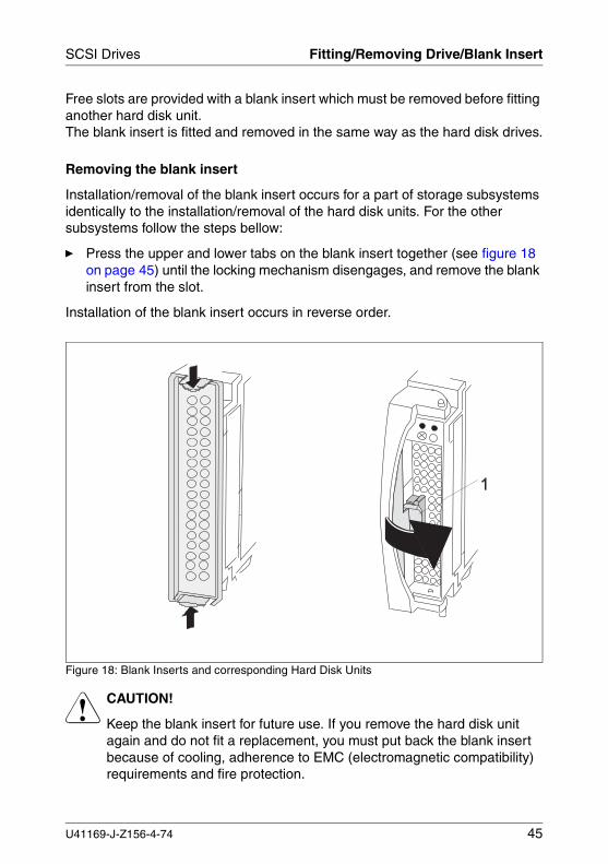
Free slots are provided with a blank insert which must be removed before fitting another hard disk unit.The blank insert is fitted and removed in the same way as the hard disk drives.
Removing the blank insert
Installation/removal of the blank insert occurs for a part of storage subsystems identically to the installation/removal of the hard disk units. For the other subsystems follow the steps bellow:
Ê Press the upper and lower tabs on the blank insert together (see figure 18 on page 45) until the locking mechanism disengages, and remove the blank insert from the slot.
Installation of the blank insert occurs in reverse order.
Figure 18: Blank Inserts and corresponding Hard Disk Units
V CAUTION!
Keep the blank insert for future use. If you remove the hard disk unit again and do not fit a replacement, you must put back the blank insert because of cooling, adherence to EMC (electromagnetic compatibility) requirements and fire protection.
U41169-J-Z156-4-74 45
Fitting/Removing Drive/Blank Insert SCSI Drives
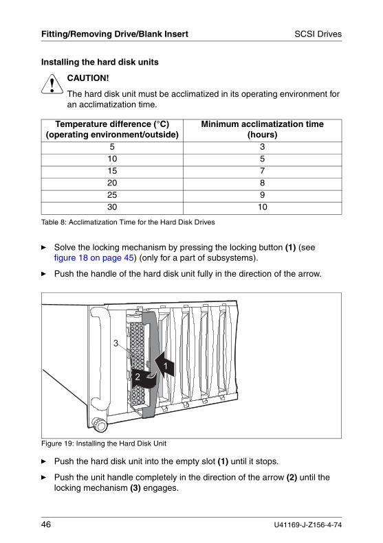
Installing the hard disk units
V CAUTION!
The hard disk unit must be acclimatized in its operating environment for an acclimatization time.
Ê Solve the locking mechanism by pressing the locking button (1) (see figure 18 on page 45) (only for a part of subsystems).
Ê Push the handle of the hard disk unit fully in the direction of the arrow.
Figure 19: Installing the Hard Disk Unit
Ê Push the hard disk unit into the empty slot (1) until it stops.
Ê Push the unit handle completely in the direction of the arrow (2) until the locking mechanism (3) engages.
Temperature difference (°C)(operating environment/outside)
Minimum acclimatization time (hours)
5 310 515 720 825 930 10
Table 8: Acclimatization Time for the Hard Disk Drives
�
�
�
46 U41169-J-Z156-4-74
SCSI Drives Fitting/Removing Drive/Blank Insert
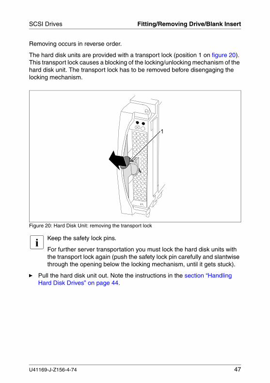
Removing occurs in reverse order.
The hard disk units are provided with a transport lock (position 1 on figure 20). This transport lock causes a blocking of the locking/unlocking mechanism of the hard disk unit. The transport lock has to be removed before disengaging the locking mechanism.
Figure 20: Hard Disk Unit: removing the transport lock
I Keep the safety lock pins.
For further server transportation you must lock the hard disk units with the transport lock again (push the safety lock pin carefully and slantwise through the opening below the locking mechanism, until it gets stuck).
Ê Pull the hard disk unit out. Note the instructions in the section “Handling Hard Disk Drives” on page 44.
U41169-J-Z156-4-74 47
Hot-Swap for SCSI Hard Disk Drive SCSI Drives
7.3 Hot-Swap for SCSI Hard Disk Drive
V CAUTION!
Only pull out the hard disk units if the green HDD busy LED is not on.
If you want to replace an SCSI hard disk drive during operation, proceed as follows:
Ê If you want to pull out a hard disk drive which is not defective, it must be set to “Offline“ beforehand via the software (e.g. Mylex + GAM).
Ê Pull the hard disk drive (defective/not defective) out by a few centimeters.
Ê Wait for at least 60 seconds.
I This period is necessary for the RAID controller to recognize that a hard disk drive has been pulled out and for the hard disk drive to come to a stop.
Ê Pull the hard disk unit right out.
Ê Insert the new hard disk unit.
When you have removed the hard disk unit and are not fitting any replacement, then fit a blank insert into the blank slot. Ensure that the blank insert engages in the slot correctly.
48 U41169-J-Z156-4-74
SCSI Drives SCSI IDs
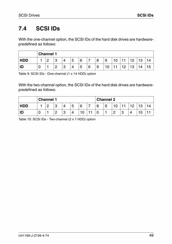
7.4 SCSI IDs
With the one-channel option, the SCSI IDs of the hard disk drives are hardware-predefined as follows:
With the two-channel option, the SCSI IDs of the hard disk drives are hardware-predefined as follows:
Channel 1
HDD 1 2 3 4 5 6 7 8 9 10 11 12 13 14
ID 0 1 2 3 4 5 6 9 10 11 12 13 14 15
Table 9: SCSI IDs - One-channel (1 x 14 HDD) option
Channel 1 Channel 2
HDD 1 2 3 4 5 6 7 8 9 10 11 12 13 14
ID 0 1 2 3 4 10 11 0 1 2 3 4 10 11
Table 10: SCSI IDs - Two-channel (2 x 7 HDD) option
U41169-J-Z156-4-74 49

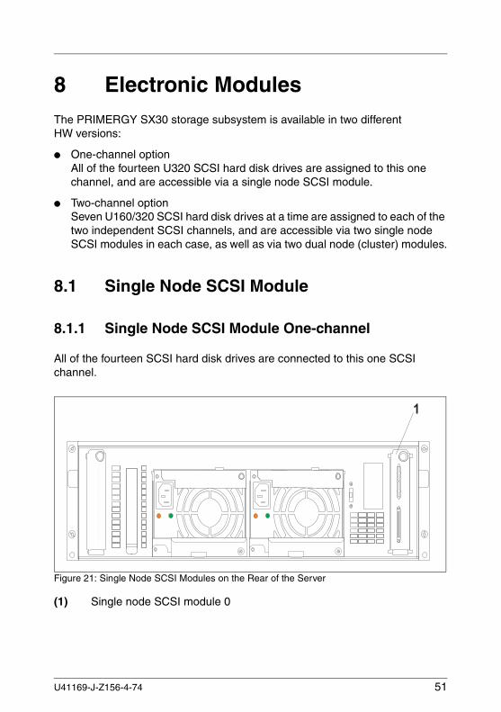
8 Electronic ModulesThe PRIMERGY SX30 storage subsystem is available in two different HW versions:
● One-channel optionAll of the fourteen U320 SCSI hard disk drives are assigned to this one channel, and are accessible via a single node SCSI module.
● Two-channel optionSeven U160/320 SCSI hard disk drives at a time are assigned to each of the two independent SCSI channels, and are accessible via two single node SCSI modules in each case, as well as via two dual node (cluster) modules.
8.1 Single Node SCSI Module
8.1.1 Single Node SCSI Module One-channel
All of the fourteen SCSI hard disk drives are connected to this one SCSI channel.
Figure 21: Single Node SCSI Modules on the Rear of the Server
(1) Single node SCSI module 0
�
U41169-J-Z156-4-74 51
Single Node SCSI Module Electronic Modules
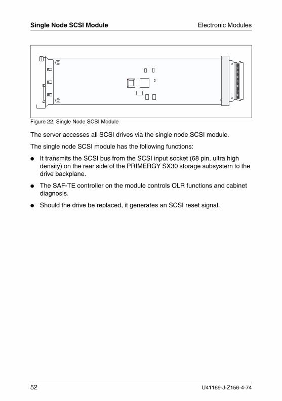
Figure 22: Single Node SCSI Module
The server accesses all SCSI drives via the single node SCSI module.
The single node SCSI module has the following functions:
● It transmits the SCSI bus from the SCSI input socket (68 pin, ultra high density) on the rear side of the PRIMERGY SX30 storage subsystem to the drive backplane.
● The SAF-TE controller on the module controls OLR functions and cabinet diagnosis.
● Should the drive be replaced, it generates an SCSI reset signal.
52 U41169-J-Z156-4-74
Electronic Modules Single Node SCSI Module
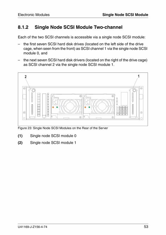
8.1.2 Single Node SCSI Module Two-channel
Each of the two SCSI channels is accessible via a single node SCSI module:
– the first seven SCSI hard disk drives (located on the left side of the drive cage, when seen from the front) as SCSI channel 1 via the single node SCSI module 0, and
– the next seven SCSI hard disk drivers (located on the right of the drive cage) as SCSI channel 2 via the single node SCSI module 1.
Figure 23: Single Node SCSI Modules on the Rear of the Server
(1) Single node SCSI module 0
(2) Single node SCSI module 1
� �
U41169-J-Z156-4-74 53
Single Node SCSI Module Electronic Modules
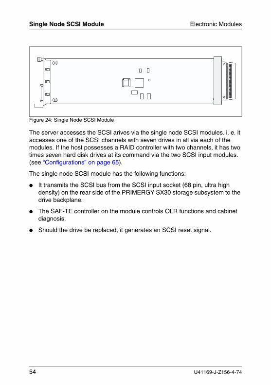
Figure 24: Single Node SCSI Module
The server accesses the SCSI arives via the single node SCSI modules. i. e. it accesses one of the SCSI channels with seven drives in all via each of the modules. If the host possesses a RAID controller with two channels, it has two times seven hard disk drives at its command via the two SCSI input modules. (see “Configurations” on page 65).
The single node SCSI module has the following functions:
● It transmits the SCSI bus from the SCSI input socket (68 pin, ultra high density) on the rear side of the PRIMERGY SX30 storage subsystem to the drive backplane.
● The SAF-TE controller on the module controls OLR functions and cabinet diagnosis.
● Should the drive be replaced, it generates an SCSI reset signal.
54 U41169-J-Z156-4-74
Electronic Modules Dual Node SCSI Module
8.2 Dual Node SCSI Module
8.2.1 Dual Node SCSI Module Two-channels
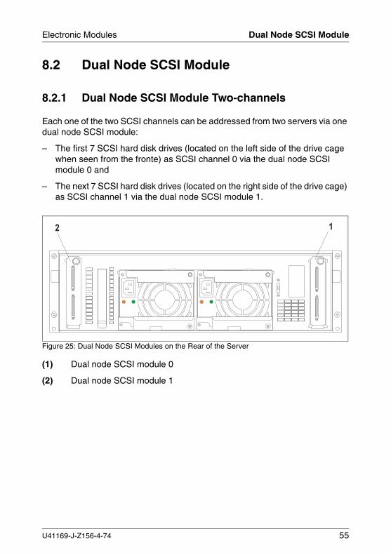
Each one of the two SCSI channels can be addressed from two servers via one dual node SCSI module:
– The first 7 SCSI hard disk drives (located on the left side of the drive cage when seen from the fronte) as SCSI channel 0 via the dual node SCSI module 0 and
– The next 7 SCSI hard disk drives (located on the right side of the drive cage) as SCSI channel 1 via the dual node SCSI module 1.
Figure 25: Dual Node SCSI Modules on the Rear of the Server
(1) Dual node SCSI module 0
(2) Dual node SCSI module 1
� �
U41169-J-Z156-4-74 55
Dual Node SCSI Module Electronic Modules
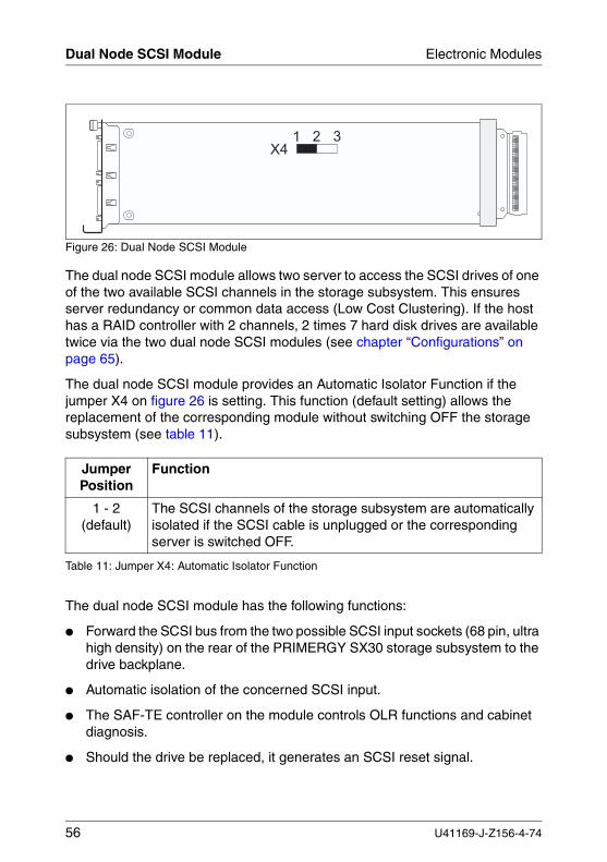
Figure 26: Dual Node SCSI Module
The dual node SCSI module allows two server to access the SCSI drives of one of the two available SCSI channels in the storage subsystem. This ensures server redundancy or common data access (Low Cost Clustering). If the host has a RAID controller with 2 channels, 2 times 7 hard disk drives are available twice via the two dual node SCSI modules (see chapter “Configurations” on page 65).
The dual node SCSI module provides an Automatic Isolator Function if the jumper X4 on figure 26 is setting. This function (default setting) allows the replacement of the corresponding module without switching OFF the storage subsystem (see table 11).
The dual node SCSI module has the following functions:
● Forward the SCSI bus from the two possible SCSI input sockets (68 pin, ultra high density) on the rear of the PRIMERGY SX30 storage subsystem to the drive backplane.
● Automatic isolation of the concerned SCSI input.
● The SAF-TE controller on the module controls OLR functions and cabinet diagnosis.
● Should the drive be replaced, it generates an SCSI reset signal.
Jumper Position
Function
1 - 2(default)
The SCSI channels of the storage subsystem are automatically isolated if the SCSI cable is unplugged or the corresponding server is switched OFF.
Table 11: Jumper X4: Automatic Isolator Function
� �
� � �
56 U41169-J-Z156-4-74
Electronic Modules Fitting/Removing a Module
8.3 Fitting/Removing a Module
Fitting/removing the two module types (single node SCSI module and/or the dual node SCSI module) occurs in the same way. The following figures show only the single node SCSI module.
V CAUTION!
Note the safety instructions and the instructions on the ESD label in chapter “Important Notes” on page 13.
V CAUTION!
The single node SCSI module may only be removed while the system is not in operation. Shut down the server before you remove the module or take the line-to-neutral voltage from the SCSI (remove power supply unit plug).
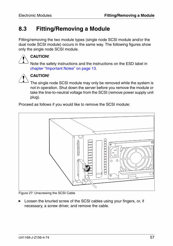
Proceed as follows if you would like to remove the SCSI module:
Figure 27: Unscrewing the SCSI Cable
Ê Loosen the knurled screw of the SCSI cables using your fingers, or, if necessary, a screw driver, and remove the cable.
U41169-J-Z156-4-74 57
Fitting/Removing a Module Electronic Modules
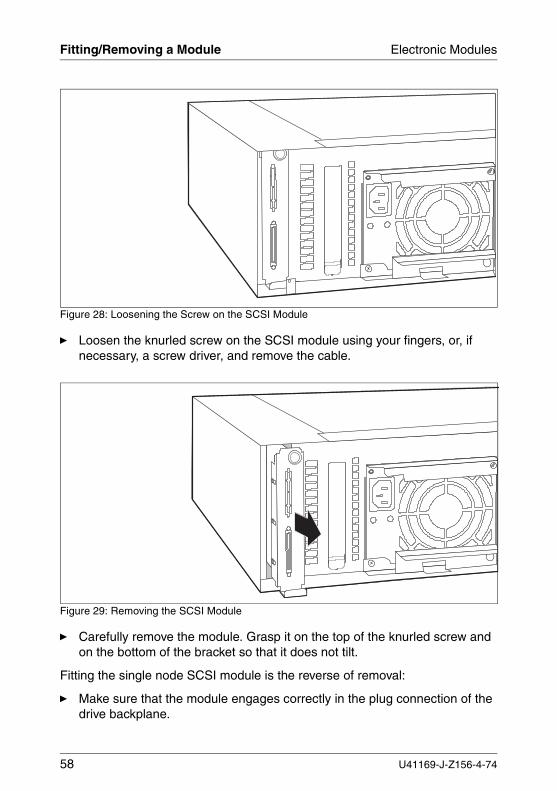
Figure 28: Loosening the Screw on the SCSI Module
Ê Loosen the knurled screw on the SCSI module using your fingers, or, if necessary, a screw driver, and remove the cable.
Figure 29: Removing the SCSI Module
Ê Carefully remove the module. Grasp it on the top of the knurled screw and on the bottom of the bracket so that it does not tilt.
Fitting the single node SCSI module is the reverse of removal:
Ê Make sure that the module engages correctly in the plug connection of the drive backplane.
58 U41169-J-Z156-4-74
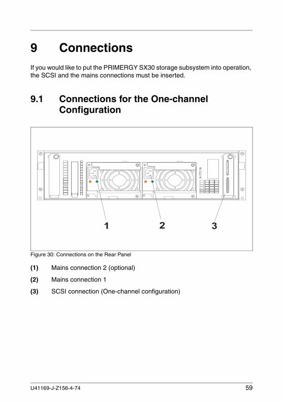
9 ConnectionsIf you would like to put the PRIMERGY SX30 storage subsystem into operation, the SCSI and the mains connections must be inserted.
9.1 Connections for the One-channel Configuration
Figure 30: Connections on the Rear Panel
(1) Mains connection 2 (optional)
(2) Mains connection 1
(3) SCSI connection (One-channel configuration)
� � � �� �
U41169-J-Z156-4-74 59
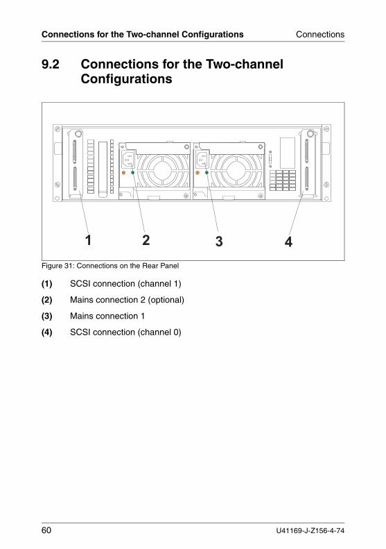
Connections for the Two-channel Configurations Connections
9.2 Connections for the Two-channel Configurations
Figure 31: Connections on the Rear Panel
(1) SCSI connection (channel 1)
(2) Mains connection 2 (optional)
(3) Mains connection 1
(4) SCSI connection (channel 0)
� � � � � �� �
60 U41169-J-Z156-4-74
Connections SCSI Connection
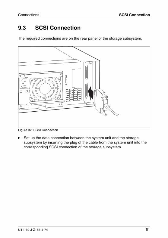
9.3 SCSI Connection
The required connections are on the rear panel of the storage subsystem.
Figure 32: SCSI Connection
Ê Set up the data connection between the system unit and the storage subsystem by inserting the plug of the cable from the system unit into the corresponding SCSI connection of the storage subsystem.
U41169-J-Z156-4-74 61
SCSI Connection Connections
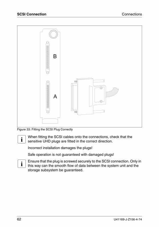
Figure 33: Fitting the SCSI Plug Correctly
I When fitting the SCSI cables onto the connections, check that the sensitive UHD plugs are fitted in the correct direction.
Incorrect installation damages the plugs!
Safe operation is not guaranteed with damaged plugs!
I Ensure that the plug is screwed securely to the SCSI connection. Only in this way can the smooth flow of data between the system unit and the storage subsystem be guaranteed.
62 U41169-J-Z156-4-74
Connections Mains Connection
9.4 Mains Connection
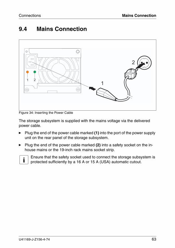
Figure 34: Inserting the Power Cable
The storage subsystem is supplied with the mains voltage via the delivered power cable.
Ê Plug the end of the power cable marked (1) into the port of the power supply unit on the rear panel of the storage subsystem.
Ê Plug the end of the power cable marked (2) into a safety socket on the in-house mains or the 19-inch rack mains socket strip.
I Ensure that the safety socket used to connect the storage subsystem is protected sufficiently by a 16 A or 15 A (USA) automatic cutout.
� �
�
�
U41169-J-Z156-4-74 63
Mains Connection with Phase Redundancy Connections
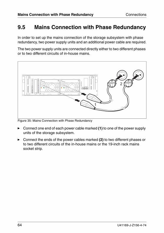
9.5 Mains Connection with Phase Redundancy
In order to set up the mains connection of the storage subsystem with phase redundancy, two power supply units and an additional power cable are required.
The two power supply units are connected directly either to two different phases or to two different circuits of in-house mains.
Figure 35: Mains Connection with Phase Redundancy
Ê Connect one end of each power cable marked (1) to one of the power supply units of the storage subsystem.
Ê Connect the ends of the power cables marked (2) to two different phases or to two different circuits of the in-house mains or the 19-inch rack mains socket strip.
�
�
64 U41169-J-Z156-4-74
10 Configurations
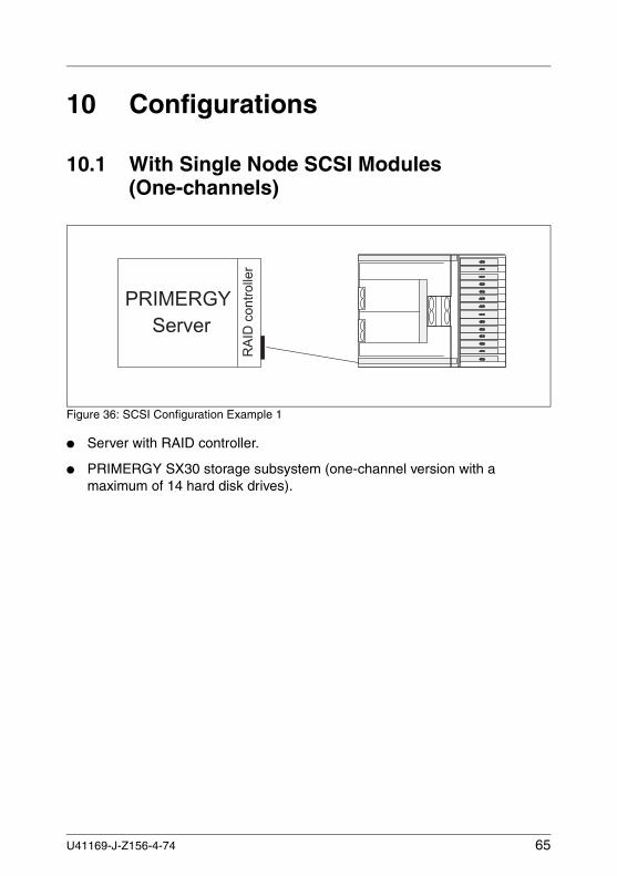
10.1 With Single Node SCSI Modules (One-channels)
Figure 36: SCSI Configuration Example 1
● Server with RAID controller.
● PRIMERGY SX30 storage subsystem (one-channel version with a maximum of 14 hard disk drives).
� � � � � � � � � � �
���������������
U41169-J-Z156-4-74 65
With Single Node SCSI Modules (Two-channels) Configurations
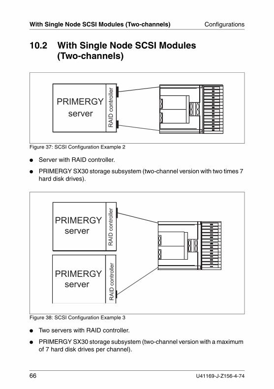
10.2 With Single Node SCSI Modules (Two-channels)
Figure 37: SCSI Configuration Example 2
● Server with RAID controller.
● PRIMERGY SX30 storage subsystem (two-channel version with two times 7 hard disk drives).
Figure 38: SCSI Configuration Example 3
● Two servers with RAID controller.
● PRIMERGY SX30 storage subsystem (two-channel version with a maximum of 7 hard disk drives per channel).
� � � � � � � � � � � �
���������������
� � � � � � � � � � � � � � � �
����
����
�������
����
����
�������
� � � � � � � � � � � � � � � �
66 U41169-J-Z156-4-74
Configurations With Dual Node SCSI Modules (Two-channel)
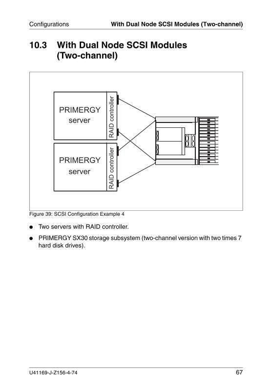
10.3 With Dual Node SCSI Modules (Two-channel)
Figure 39: SCSI Configuration Example 4
● Two servers with RAID controller.
● PRIMERGY SX30 storage subsystem (two-channel version with two times 7 hard disk drives).
� � � � � � � � � � � �
����
����
������
�
� � � � � � �
� � � � �
����
����
������
�
U41169-J-Z156-4-74 67

11 Installation
11.1 Installation Steps
V CAUTION!
The storage subsystem should not be subjected to any extreme environ-mental conditions (see section “Technical Data” on page 10). Protect it from dust, moisture and heat.
The following installation steps are described in detail in other sections of this chapter:
Ê Unpacking the storage subsystem.
Ê Setting up the floorstand model or insert the rack model into the rack.
Ê Cabling the storage subsystem (see section “SCSI Connection” on page 61).
Ê Setting the desired system parameters.
Ê Connecting the storage subsystem to the mains voltage (see section “Mains Connection” on page 63 or section “Mains Connection with Phase Redun-dancy” on page 64).
Ê Switching ON the storage subsystem.
U41169-J-Z156-4-74 69
Unpacking the Storage Subsystem Installation
11.2 Unpacking the Storage Subsystem
V CAUTION!
Please note the safety instructions in chapter “Important Notes” on page 13.
Enlist the help of others to carry the storage subsystem.
You should retain the original packing of the storage subsystem for possible further transport.
Ê Unpack all parts.
Ê Check the contents of the package for visible transport damage.
Ê Check whether the delivery matches the information given on the delivery note.
Ê Check whether the first page of the guarantee booklet has been completed in full.
If you find transport damage or inconsistencies between the contents of the package and the delivery note, inform your supplier immediately!
11.3 Setting Up the Floorstand Model
Set up the storage subsystem at the intended installation site.
Note the following:
– The equipment must be protected against direct sunlight.– The required minimum distances for operating and maintenance areas must
be adhered to. – In order to connect the server, the rear panel of the storage subsystem must
be accessible.– The mains plug must be accessible easily and safely.– The free space in front of and behind the storage subsystem must be at least
200 mm so that the storage subsystem is ventilated sufficiently.
70 U41169-J-Z156-4-74
Installation Installing/Uninstalling the Subsystem in/from the Rack
11.4 Installing and Uninstalling the Storage Subsystem in and from the Rack
V ● Please observe the safety precautions and references to mounting into the rack in chapter “Important Notes” on page 13.
● At least two people are needed to position the server in the rack.
● The rack can tip over if more than one unit is removed.
11.5 Requirements of the Rack
The rack systems of the Fujitsu Siemens Computers GmbH (19-Inch (Classic) Rack, DataCenter Rack and PRIMECENTER Rack) fully support the installation of the PRIMERGY server systems. The installation in rack systems of several other manufacturers (3rd-Party Rack) available at present is supported to a large part.
To accommodate the ventilation concept and ensure proper ventilation of the components in the rack, any unused areas must be closed using dummy covers.
Power is supplied via the socket strips available in the rack.
The mounting of the cable management is described in detail in the Technical Manual for the respective rack.
U41169-J-Z156-4-74 71
Requirements of the Rack Installation
The main features of the rack systems of the Fujitsu Siemens Computers GmbH are:
PRIMECENTER Rack
– Frontally bolted telescopic rails or sliding rails.
The rails are provided with a linear alignment facility to ensure also an adjustment to different rack depths (except in the rear left area, where a support bracket is used).
– Extended cable management within the lateral rack area.
DataCenter Rack
– Frontally or laterally (using a grid) bolted telescopic rails or sliding rails (except within the rear left area, where a support bracket is used).
– Extended cable management within the lateral rack area.
19-Inch (Classic) Rack
– Laterally (using a grid) bolted telescopic rails or sliding rails.
– Cable management using a hinged cable carrier.
The mounting of the telescopic rails and the assembly brackets in the different racks is described in the next sections.
72 U41169-J-Z156-4-74
Installation Requirements of the Rack
When installing rack systems of several other manufacturers, the following applies:
3rd-Party Rack
Some general conditions must observed:
– Installation dimensions (see the dimensions shown in figure 40 on page 74).
– The operability of the server safety mechanisms, e.g. stoppers or holding back systems, must be guaranteed.
– The form of the rack support uprights must ensure the frontal screwing on of the telescope rails.
– Frontally bolted telescopic rails or gliding rails.The rails are provided with a linear alignment facility to ensure also an adjustment to different rack depths.
– No support for the cable management delivered with the mounting kit.– Climatic conditions.
An air intake unimpeded to a large extent in the rack front and an air discharge in the rear cover of the rack are necessary for the ventilation of the installed server.In principle, the ventilation concept envisages that the necessary cooling is reached by the horizontal self-ventilation of the installed devices (air flow from the front to the rear).
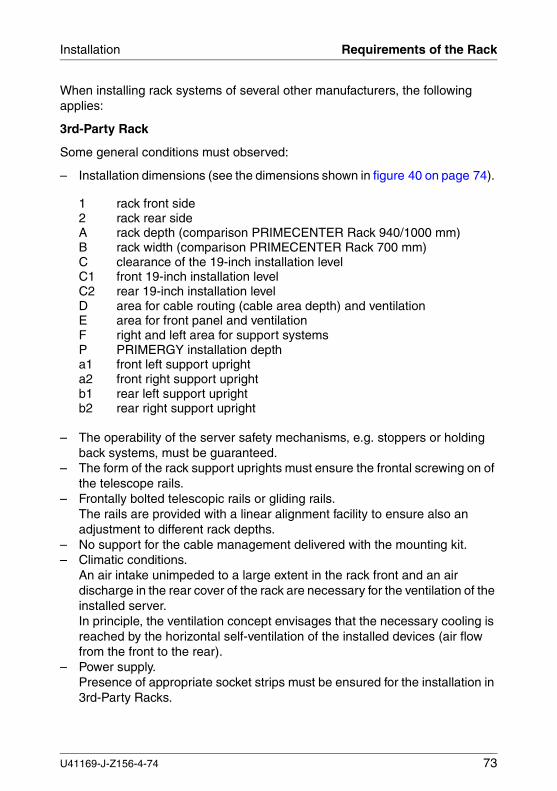
– Power supply.Presence of appropriate socket strips must be ensured for the installation in 3rd-Party Racks.
1 rack front side2 rack rear sideA rack depth (comparison PRIMECENTER Rack 940/1000 mm)B rack width (comparison PRIMECENTER Rack 700 mm)C clearance of the 19-inch installation levelC1 front 19-inch installation levelC2 rear 19-inch installation levelD area for cable routing (cable area depth) and ventilationE area for front panel and ventilationF right and left area for support systemsP PRIMERGY installation deptha1 front left support uprighta2 front right support uprightb1 rear left support uprightb2 rear right support upright
U41169-J-Z156-4-74 73
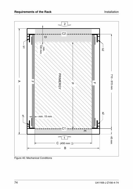
Requirements of the Rack Installation
Figure 40: Mechanical Conditions
710 - 8
15 m
m
C (450 mm +1)
b2
a2
a1
b1
B
-0
E
45 m
m
1
2
D
min. 15 mm
FF
C1
C2
min
. 100 m
m
PR
IME
RG
Y
A
P
74 U41169-J-Z156-4-74
Installation Installing in the Different Racks
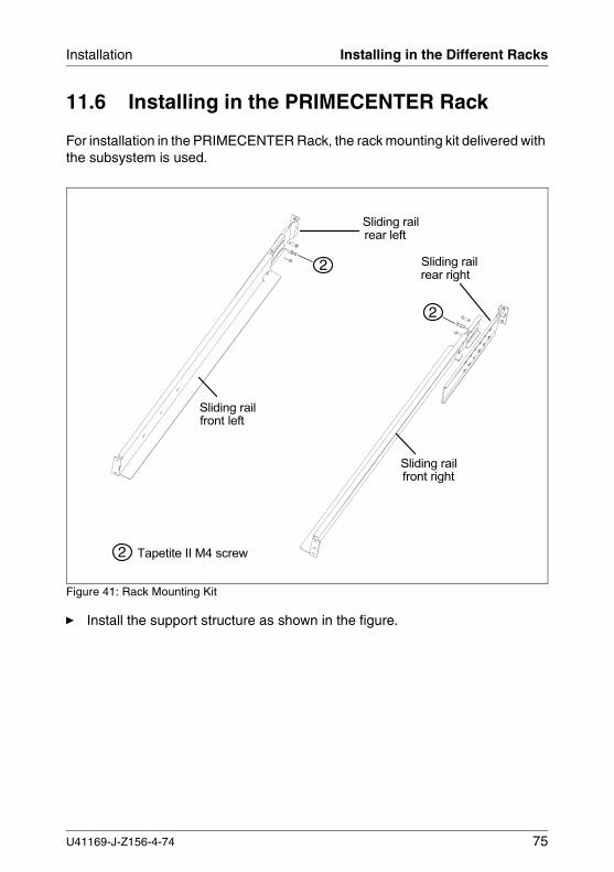
11.6 Installing in the PRIMECENTER Rack
For installation in the PRIMECENTER Rack, the rack mounting kit delivered with the subsystem is used.
Figure 41: Rack Mounting Kit
Ê Install the support structure as shown in the figure.
2
2
2 Sliding railrear right
Sliding railfront left
Tapetite II M4 screw
Sliding railrear left
Sliding railfront right
U41169-J-Z156-4-74 75
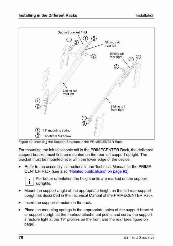
Installing in the Different Racks Installation
Figure 42: Installing the Support Structure in the PRIMECENTER Rack
For mounting the left telescopic rail in the PRIMECENTER Rack, the delivered support bracket must first be mounted on the rear left support upright. The bracket must be mounted level with the lower edge of the device.
Ê Refer to the assembly instructions in the Technical Manual for the PRIME-CENTER Rack (see also “Related publications” on page 93).
I For better orientation the height units are marked on the support uprights.
Ê Mount the support angle at the appropriate height on the left rear support upright as described in the Technical Manual of the PRIMECENTER Rack.
Ê Insert the support structure in the rack.
Ê Place the mounting springs in the appropriate holes of the support bracket or support upright at the marked attachment points and screw the support structure tight at the 19“ profiles on the front and the rear (see figure on page).
Sliding railrear right
Sliding railfront left
Tapetite II M4 screw
Support bracket 1HU
Sliding railrear left
Sliding railfront right
19" mounting spring1
2
1
2
1
2
12
12
1 2
2
2
76 U41169-J-Z156-4-74
Installation Installing in the Different Racks
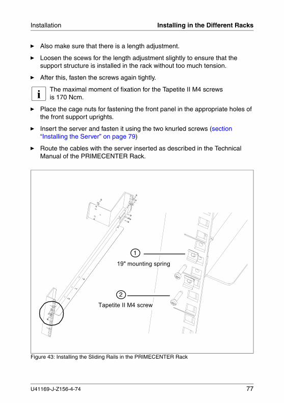
Ê Also make sure that there is a length adjustment.
Ê Loosen the scews for the length adjustment slightly to ensure that the support structure is installed in the rack without too much tension.
Ê After this, fasten the screws again tightly.
I The maximal moment of fixation for the Tapetite II M4 screws is 170 Ncm.
Ê Place the cage nuts for fastening the front panel in the appropriate holes of the front support uprights.
Ê Insert the server and fasten it using the two knurled screws (section “Installing the Server” on page 79)
Ê Route the cables with the server inserted as described in the Technical Manual of the PRIMECENTER Rack.
Figure 43: Installing the Sliding Rails in the PRIMECENTER Rack
19" mounting spring
Tapetite II M4 screw
2
1
U41169-J-Z156-4-74 77
Installing in the Different Racks Installation
11.7 Installing in the DataCenter Rack
The installation in the DataCenter Rack is carried out in the same way as was described for the PRIMECENTER Rack.
11.8 Installing in the Classic Rack
To install the server in the Classic (19-inch) Rack, please use a sliding rail of the rack manufacturer.
The rack mounting kit delivered with the server cannot be used for this rack.
11.9 Installing in 3rd-Party Racks
If your rack matches the general conditions for 3rd-Party Racks, you can use parts of the rack mounting kit delivered with the server. The delivered support bracket and the cable management may not be required.
For installing the server in a 3rd-Party Rack the following parts from the rack mounting kit are required:
– Two telescopic rails (assembled)– Eight mounting springs with Tapetite II M4 screws.
Ê Refer to the original manual of the rack manufacturer regarding the mechanical installation and/or the climatic conditions.
V When installing the server installation in 3rd-Party Racks, make sure that there is air flow in the rack from the front to the rear.
I A number of parts of the delivered rack mounting kit may not be compatible, because original parts of the 3rd-Party Rack must to be used.
V Make sure that the server security mechanismus, e. g. stoppers and holding back systems, will function properly.
Ê Insert the server (see section “Installing the Server” on page 79).
Ê Route the cables as described in the original manual of the rack.
Ê Secure the server on the front panel using two knurled screws.
78 U41169-J-Z156-4-74
Installation Installing the Server
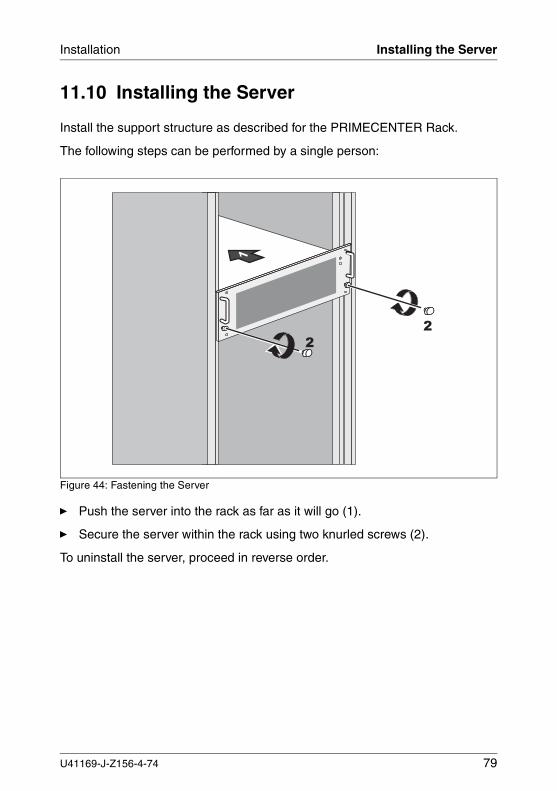
11.10 Installing the Server
Install the support structure as described for the PRIMECENTER Rack.
The following steps can be performed by a single person:
Figure 44: Fastening the Server
Ê Push the server into the rack as far as it will go (1).
Ê Secure the server within the rack using two knurled screws (2).
To uninstall the server, proceed in reverse order.
��
U41169-J-Z156-4-74 79
Routing the Leads Installation
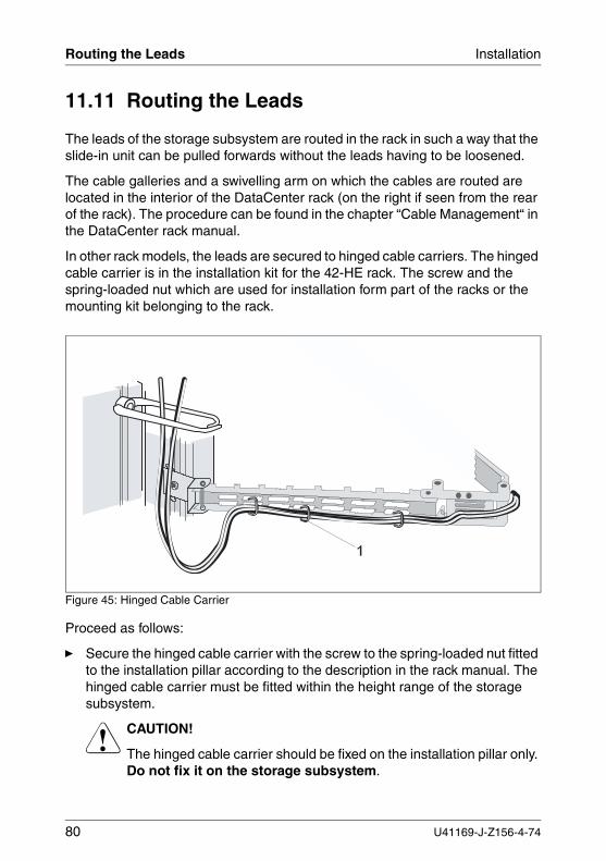
11.11 Routing the Leads
The leads of the storage subsystem are routed in the rack in such a way that the slide-in unit can be pulled forwards without the leads having to be loosened.
The cable galleries and a swivelling arm on which the cables are routed are located in the interior of the DataCenter rack (on the right if seen from the rear of the rack). The procedure can be found in the chapter “Cable Management“ in the DataCenter rack manual.
In other rack models, the leads are secured to hinged cable carriers. The hinged cable carrier is in the installation kit for the 42-HE rack. The screw and the spring-loaded nut which are used for installation form part of the racks or the mounting kit belonging to the rack.
Figure 45: Hinged Cable Carrier
Proceed as follows:
Ê Secure the hinged cable carrier with the screw to the spring-loaded nut fitted to the installation pillar according to the description in the rack manual. The hinged cable carrier must be fitted within the height range of the storage subsystem.
V CAUTION!
The hinged cable carrier should be fixed on the installation pillar only. Do not fix it on the storage subsystem.
80 U41169-J-Z156-4-74
Installation Routing the Leads
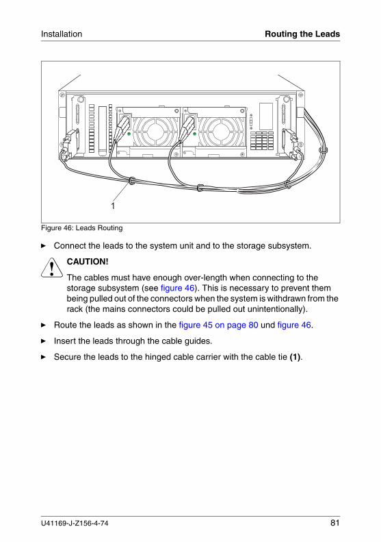
Figure 46: Leads Routing
Ê Connect the leads to the system unit and to the storage subsystem.
V CAUTION!
The cables must have enough over-length when connecting to the storage subsystem (see figure 46). This is necessary to prevent them being pulled out of the connectors when the system is withdrawn from the rack (the mains connectors could be pulled out unintentionally).
Ê Route the leads as shown in the figure 45 on page 80 und figure 46.
Ê Insert the leads through the cable guides.
Ê Secure the leads to the hinged cable carrier with the cable tie (1).
�
U41169-J-Z156-4-74 81
Connecting/Disconnecting Leads Installation
11.12 Connecting and Disconnecting Leads
V CAUTION!
The power plug must be pulled out!Read the documentation for the external device before connecting any leads.Lead may neither be connected nor disconnected during thunderstorms.When disconnecting a lead, always hold it by the plug, never pull on the wire!
When connecting or disconnecting leads, follow the sequence described below:
Connecting leads
Ê Switch OFF all the relevant devices.
Ê Pull the power plugs of all the relevant devices out of their sockets.
Ê Connect all the leads to the server and the storage subsystem. Mark the leads and make a note of the function of each lead. Always note the safety instructions in chapter “Important Notes” on page 13.
Ê Connect the power plugs to appropriately protected safety sockets. For rack models make sure that the power cables of the devices are connected in such a way that the power is split equally among the three phases (L1, L2, L3) (you can find further information in the manual for the19-inch rack).
Ê For devices with hinged cable carriers, secure the leads to the hinged cable carrier with cable ties.
Disconnecting leads
Ê Switch OFF all the relevant devices.
Ê Pull the power plugs of all the relevant devices out of their sockets.
Ê Disconnect all the cables on the server and on the storage subsystem.
82 U41169-J-Z156-4-74
Installation Switching the Subsystem ON/OFF
11.13 Switching the Storage Subsystem ON/OFF
The PRIMERGY SX30 storage subsystem can be switched ON or OFF via its own operating switch or via TerminationPower of the controller in the server.
V CAUTION!
If the storage subsystem is not switched ON by a connected server, the storage subsystem must always be switched ON before the connected server.
U41169-J-Z156-4-74 83

12 Fault ClearingV CAUTION!
Note the safety instructions in the “Safety, Guarantee and Ergonomics“ manual and in section “Connecting and Disconnecting Leads” on page 82.
If a fault occurs, attempt to rectify it in accordance with the measures set out below:
● Which are described in this chapter,
● Which are described in the documentation for the connected server and the disk array controller used.
If you cannot rectify the fault, proceed as follows:
Ê Note the steps that you have performed and the state which was active when the error occurred. Note also any error message which may have been displayed.
Ê Switch OFF the connected server.
Ê Switch OFF the storage subsystem and pull out the power plug.
Ê Contact our service organization.
U41169-J-Z156-4-74 85
Problem Solutions and Tips Fault Clearing
12.1 Problem Solutions and Tips
The following sections describe irregularities which can be observed on the storage subsystem in case of faults. Their possible causes are named and there are instructions for fault clearing.
12.1.1 Power Supply Indication (Front)
If the power supply indication is green the device is switched on and the power supply and power supply units are OK.
12.1.1.1 Power supply indication remains dark
Power cable not connected correctly
Ê Ensure that the power cable on the storage subsystem and the safety socket are connected correctly.
Power supply units defective
Ê Check the LEDs of the power supply units.
If the operating indication (green LED) is dark on the power supply units and the error indication (amber LED) is on, the power supply units are defective.
Ê Replace the power supply units.
12.1.1.2 Power supply indication is yellow
One of the installed power supply units has failed
Ê Check which one of the power supply units has failed. On the rear panel of the storage subsystem there is an amber LED and a green LED on all the power supply units. If only the amber LED is ON, the power supply unit is defective or the power supply don’t receive power.
86 U41169-J-Z156-4-74
Fault Clearing Problem Solutions and Tips
Ê Replace the defective power supply unit (see section “Replacing the Power Supply Unit” on page 36).
The problem is cleared if
– the green LED on the power supply unit is ON and
– the power supply indication on the front panel of the storage subsystem is green.
12.1.1.3 Power supply indication is flashing orange
The device is switched OFF and in the standby mode.
Ê Switch the device ON (see section “Switching the Storage Subsystem ON/OFF” on page 83).
Ê If the LED remains orange, the power supply units may have failed. Replace the power supply units. If the LED then still remains orange, contact our service organization.
12.1.2 Cooling Status
If the cooling status LED is green, both the installed fans and the interior temper-ature of the storage subsystem are OK.
12.1.2.1 Cooling status LED is yellow
I This indication means that a redundant fan is defective, but the temper-ature is OK.
One of the fans is defective
I In this case, the status LED on the fan module is yellow (see section “Fan LED” on page 26).
Ê Replace the fan module (see section “Fitting/Removing the Fan Module” on page 40).
U41169-J-Z156-4-74 87
Problem Solutions and Tips Fault Clearing
V CAUTION!
It is imperative when replacing the fan module during operation that you take no longer than 30 seconds, since otherwise the temperature in the storage subsystem can exceed the permissible limit values.
After the fan module has been replaced successfully, both the status LED on the fan module and the cooling status LED must be green again.
12.1.2.2 Cooling status LED is orange
In this case there is a cooling fault.
Ê Check whether or not all the fans have failed. In this case the status LED on the fan module is orange (see chapter “Fan Module” on page 39).
If the status LED on the fan module is green or yellow, the temperature in the device is too high although the fans (or at least one of the fans) are working. Check whether or not the ambient temperature is too high or the air outlet on the rear panel of the device is obstructed.
All the fans have failed
Ê Immediately shut down the system to prevent overheating damage in the device.
Ê Replace the fan module (see section “Fitting/Removing the Fan Module” on page 40).
V CAUTION!
It is imperative when replacing the fan module during operation that you take no longer than 30 seconds, since otherwise the temperature in the storage subsystem exceeds the permissible limit values.
12.1.3 Server Management Status
This indication can be activated manually from the ServerView. Evaluation is performed with a later version of the storage subsystem.
88 U41169-J-Z156-4-74
Fault Clearing Problem Solutions and Tips
12.1.4 Storage Subsystem Switches OFF
Temperature too high
The temperature sensors have measured an increased temperature and the server has shut down the system.
Ê Wait until the storage subsystem has cooled down.
12.1.5 System does not Start Up after New Drives have been Installed
SCSI configuration incorrect (disk array controller)
Ê Call up the configuration menu and check the drive settings (device config-uration) and the additional settings (advanced configuration options).
12.1.6 Hard Disk Drive Operating Indication does not Come ON
Ê Check whether the hard disk drive has been correctly installed and locked (see section “Fitting/Removing Drive/Blank Insert” on page 44).
Hard disk unit or SCSI backplane is defective
Ê Replace the hard disk unit. If the operating indication is still OFF, the SCSI backplane is defective. Contact the service organization.
12.1.7 Drives “dead” on System Start
Incorrect cabling
Ê Ensure that the cabling and SCSI channel assignment correspond to the original status.
Configuration of the disk array controller incorrect
Ê Call up the RAID utility from the configuration disk or from the controller BIOS of the RAID controller, and correct the settings for the drives.
You will find further notes in the disk array controller documentation.
U41169-J-Z156-4-74 89
Problem Solutions and Tips Fault Clearing
12.1.8 RAID Controller Indicates the Added Drive to be Incorrect
This error message can have the following cause:
RAID controller not configured for the drive
Installation was occured with the system switched off.
Ê Configure the RAID controller retroactively for the drive. You will find infor-mation on this topic in the RAID controller documentation
or
Ê Re-install the drive with the system switched ON.If the drive is still found to be incorrect, it must be replaced (see section “Hot-Swap for SCSI Hard Disk Drive” on page 48).
12.1.9 Storage Subsystem cannot be Switched OFF by the Server
A server connected to another SCSI module is still switched ON
I As long as one of the servers is switched ON, the storage subsystem remains switched ON via TERMPower.
The ON/OFF switch is in the “local on” position
Ê Set the ON/OFF switch to the “remote on” position (see section “ON/OFF Switch” on page 27).
90 U41169-J-Z156-4-74
AbbreviationsA
Ampere
CEEuropean Community
DACDisk Array Controller
DCDirect Current
EGBElectrostatically Sensitive Components
ESDElectrostatic Discharge
HDDHard Disk Drive
LANLocal Area Network
LEDLight Emitting Diode
LWLFiber Optics
OLROnLine Replacement
PCIPeripheral Component Interconnect
RAIDRedundant Arrays of Independent Disks
U41169-J-Z156-4-74 91
Abbreviations
SAF-TESCSI Accessed Fault-Tolerance Enclosures
SCASingle Connector Attachment
SCSISmall Computer System Interface
UHDUltra High Density
92 U41169-J-Z156-4-74
Related publicationsPlease apply to your local office for ordering the manuals.
[1] Safety, Guarantee and Ergonomics
[2] 19-Zoll-Rack für PRIMERGY- und RM-Systeme19” Rack for PRIMERGY and RM Systems Technisches Handbuch/Technical manual
[3] PRIMERGY DataCenter Rack Technisches Handbuch/Technical manual
[4] PRIMERGY SX30Operating Manual Microsoft Server Clustering under Microsoft Windows 2000 Advanced Server Hardware Installation and Configuration Guide
[5] PRIMERGY ServerStart BundleOperating Manual
U41169-J-Z156-4-74 93

Index
AAC power distribution 63acclimatization time 46adhesive labels on plastic casingparts 18approval certification 11
Bblank insert
fitting/removing 44blank insert, hard disk drive 45
Ccage nut 76, 78CE label 11, 16clip
for telescopic rail 76, 77cluster 7
Low Cost Clustering 56cooling
fan module 39
Ddisposal of equipment 18drive "dead" 89dual node SCSI module 56
fitting 58removal 57
Eelectrical data 10electromagnetic compatibility 16EMC 45EMC guideline 11emitted interference 11environmental conditions 10environmental protection 18ergonomics 11
Ffan LED 26, 39
fan module 39removal 40replacement 39
floorstand model 70
Hhard disk drive
acclimatization time 46blank insert 45fitting/removing 44hot-swap 48replace online 48SCSI-ID 49
hard disk LED does not come on 89height units 7, 76, 78high availability 35hot-swap 48housing
opening 31
Iindicator elements
control LEDs for the drives 21operating status LEDs 21
Lleads
connecting 82disconnecting 82
Low Cost Clustering 56low voltage directive 16
Mmains connection 63
phase redundancy 64mains voltage status 23manufacturer’s notes 16
Nnoise immunity 11noise level 11
U41169-J-Z156-4-74 95
Index
OON/OFF switch 27operating status LEDs
cooling status 22mains voltage status 22server management status 22
operating status LEDs, meaning 23
Ppacking 18plastic casing parts, adhesive
labels 18power supply indication dark 86power supply unit
coding 38LEDs 28redundancy 35replacement 36
product safety 11
Rrack assembly kit
mounting 78radio suppression 16recycling, equipment 18returning, equipment 18
SSAF TE controller 52safety instructions 13SAF-TE-Controller 54saving energy 18SCSI configurations 65
with dual node SCSI modules 67with SCSI single input
modules 65SCSI connection 61SCSI ID 49server
height units 76, 78mounting rack assembly kit 78
ServerView 7side cover
removing/mounting 32
single node SCSI module 54fitting 58removal 57
spring nut 76status LEDs 21structure of the manual 8support angle 76system does not start up 89
Ttelescopic rail
clip 76, 77
Uunpacking 70
96 U41169-J-Z156-4-74

Comments on PRIMERGY SX30Storage Subsystem
U41169-J-Z156-4-74
CommentsSuggestionsCorrections
✁
Submitted by
Fujitsu Siemens Computers GmbHUser Documentation81730 MünchenGermany
Fax: (++49) 700 / 372 00000
Internet: [email protected]://manuals.fujitsu-siemens.com

Comments on PRIMERGY SX30Storage Subsystem
U41169-J-Z156-4-74
CommentsSuggestionsCorrections
✁
Submitted by
Fujitsu Siemens Computers GmbHUser Documentation81730 MünchenGermany
Fax: (++49) 700 / 372 00000
Internet: [email protected]://manuals.fujitsu-siemens.com


Information on this document On April 1, 2009, Fujitsu became the sole owner of Fujitsu Siemens Compu-ters. This new subsidiary of Fujitsu has been renamed Fujitsu Technology So-lutions.
This document from the document archive refers to a product version which was released a considerable time ago or which is no longer marketed.
Please note that all company references and copyrights in this document have been legally transferred to Fujitsu Technology Solutions.
Contact and support addresses will now be offered by Fujitsu Technology So-lutions and have the format …@ts.fujitsu.com.
The Internet pages of Fujitsu Technology Solutions are available at http://ts.fujitsu.com/... and the user documentation at http://manuals.ts.fujitsu.com.
Copyright Fujitsu Technology Solutions, 2009
Hinweise zum vorliegenden Dokument Zum 1. April 2009 ist Fujitsu Siemens Computers in den alleinigen Besitz von Fujitsu übergegangen. Diese neue Tochtergesellschaft von Fujitsu trägt seit-dem den Namen Fujitsu Technology Solutions.
Das vorliegende Dokument aus dem Dokumentenarchiv bezieht sich auf eine bereits vor längerer Zeit freigegebene oder nicht mehr im Vertrieb befindliche Produktversion.
Bitte beachten Sie, dass alle Firmenbezüge und Copyrights im vorliegenden Dokument rechtlich auf Fujitsu Technology Solutions übergegangen sind.
Kontakt- und Supportadressen werden nun von Fujitsu Technology Solutions angeboten und haben die Form …@ts.fujitsu.com.
Die Internetseiten von Fujitsu Technology Solutions finden Sie unter http://de.ts.fujitsu.com/..., und unter http://manuals.ts.fujitsu.com finden Sie die Benutzerdokumentation.
Copyright Fujitsu Technology Solutions, 2009