Embed Size (px)
Citation preview
Pro-WedgeTM Operator’s Manual Rev A.doc i
Pro-WedgeTM
Model: VM-20/A and VM-20/3/A
Operator’s Manual
Pro-WedgeTM Operator’s Manual Rev A.doc
ii
Copyright 2005 by DEMTECH Services, Inc.
All Right Reserved
Scope of Manual:
This manual contains procedures for general unpacking, set-up, and operation of your DEMTECH Services, Inc. Pro-Wedge.
The text of this publication, or any part thereof, may not be reproduced or transmitted in any form or by any means, electronic or mechanical, including photocopying, recording, storage in an information retrieval system, or otherwise, without prior written permission of DEMTECH Services, Inc.
Notice Patents have been granted and/or patent applications are pending or are in the process of preparation on all DEMTECH Services, Inc. developments. The material in the manual is for informational purposes only and is subject to change without notice. DEMTECH Services, Inc. assumes no responsibility for any errors that may appear in this manual.
Printed in the USA
Manual Number: VM-20, Rev A
DEMTECH Services, Inc. 6414 Capitol Avenue
Diamond Springs, CA 95619 U.S.A. Telephone: (530) 621-3200 Toll Free: (888) 324-9353
Fax: (530) 621-0150 Web Site: www.demtech.com
Pro-WedgeTM Operator’s Manual Rev A.doc
iii
Table of Contents
Introduction………………………………………………….…..…...ii
Safety Precautions ........................................................................ ..….v
Section 1 General Safety Information……………………………..…..1
1.1 Intended Use………………………………………………..…1 1.2 Maintenance……………………………………………….….1 Section 2 Unpacking and Power Connection (Start-up) .............. .….2
2.1 Unpacking .......................................................................... .….2
2.2 Electrical Plug Connection................................................. .….2
2.3 Power Requirements .......................................................... .….2
2.4 Generator Recommendation............................................... .….3
2.5 Extension Cords…………………………….……….….….....3 2.6 Accessories………………………………………….….…......3 Section 3 Material Set-up ................................................................. ......4
3.1 (Set-up) Nip Pressure Adjustment………………….…….…...5 3.2 (Set-up) Upper Contour Roller Adjustment………………......7 Upper Contour Spring/Roller Configuration Chart ....................8
Pro-WedgeTM Operator’s Manual Rev A.doc
iv
Removing-Upper Contour Roller Assembly……………..……9
3.3 (Set-up) Lower Contour Roller Adjustment……………....….10
3.4 (Set-up) Wedge Fore/Aft Adjustment…………………..……12
Section 4 Welding Procedure (Operation)..................................... ....14
4.1. Power-up................................................................................ ....14
4.2. Setting Wedge Temperature………………………..…. .…...…14 4.3. Setting Weld Speed……………………………...………..……14
4.4. Starting a Weld ...................................................................... .....16
4.5. Ending a Weld ...................................................................... .....16
4.6. Shutdown……………………………………………………….17 Section 5 Reference Documents……………………………………....17
5.1 Appendix A, Welding Speed/Temperature Chart……………….…..17 5.2 Appendix B, Speed Setting vs. Actual Travel Speed Chart…………17 5.3 Appendix C, Product Information Brochure…………………...…....17 5.4 Appendix D, Product Warranty……………………..........................17 5.5 Appendix E, Spare Parts Identification Photos……..……………….17
Pro-WedgeTM Operator’s Manual Rev A.doc
v
Safety Precautions Safety precautions for operating personnel: WARNING 1: Operating personnel should perform only the procedures described and recommended in this manual. Only qualified service personnel familiar with electrical shock hazards and mechanical entanglement hazards present inside the equipment should perform disassembly or corrective maintenance of the equipment. WARNING 2: To avoid shock hazards, the equipment must be grounded with an adequate earth ground in accordance with local and national electrical codes. WARNING 3: The locations of potentially dangerous voltages and other hazards are identified and labeled on the equipment. Be careful to observe these warnings when installing, operating, maintaining or servicing the equipment. Observe all warnings in this manual. WARNING 4: Make sure to turn off the equipment power and remove the ~ (ac) line cord from the power outlet before attempting to service the equipment. Do not perform service unless you are qualified and trained to do so. CAUTION 1: Observe the precautions given on the equipment and within this manual to prevent damage to the equipment. CAUTION 2: Before connecting the equipment to its electrical power source, check that the ~ (ac) voltage, frequency and current to be supplied to the equipment are correct and match the serial plate affixed to the system. CAUTION 3: Use proper handling and packaging procedures for Electro-Static Discharge (ESD) sensitive circuit boards. Assume that all circuit boards are sensitive to potential damage from ESD. CAUTION 4: Unauthorized personnel should not remove from the equipment those panels or covers that are provided for protection and/or require a tool to remove.
Pro-Wedge Operator's Manual Rev A.doc Page 1
Section 1: General Safety Information The Pro-Wedge is a high voltage piece of equipment. Always disconnect the power source before performing service and maintenance to the unit. Never pull or carry welder by the power cord or electrical connection. Always keep slack in extension cord while in operation to avoid damage to the power connection. Keep hands and other body parts clear of heating wedge and elements when hot. Always use Pro-Wedge in a well-ventilated area when welding materials such as PVC that produce toxic fumes. Do not inhale toxic fumes when present. Do not operate near flammable materials. Do not apply flammable liquids to seam area. Allow unit to cool down for at least 5 minutes before putting back into shipping/storage case. Protect unit from exposure to direct rainfall or standing water. Never attempt to weld in standing water. 1.1. Intended Use For additional product information please refer to the product data sheet located in Appendix C of this manual. The Pro-Wedge has been manufactured according to the latest technology and current safety regulations. However, improper use or abuse may lead to hazardous conditions for the user or third party or damage to the unit. Always have this manual handy at the location where the Pro-Wedge is being used so that it can be referred to quickly and easily. The technician assigned to operate this welder must have read through and become familiar with this manual before starting work, particularly the section on safety. Do not make changes or modifications to the Pro-Wedge relative to safety without contacting the manufacturer for advice. 1.2. Maintenance Maintenance, inspection and adjustment of the Pro-Wedge may only be carried out by qualified personnel. Before removing or installing spare parts or performing other repair operations to the Pro-Wedge, consult the manufacturer for advice on proper procedures. This will help insure a safe and successful outcome. Always make sure all screw connections are tight before attempting to operate the unit after maintenance or repair. Also make sure all covers, guards, and other safety devices have been reinstalled before use.
Pro-Wedge Operator's Manual Rev A.doc Page 2
Section 2: Unpacking, Power Connection, and Accessories
2.1. Unpacking
The Pro-Wedge hot wedge welder is delivered to you in a sturdy, reusable shipping/storage case. The custom foam insert protects the unit from damage during shipping and should be left in the case at all times. When the unit is out of the case, make sure the lid is closed to avoid dirt, dust and rain from getting inside. Once the Pro-Wedge has been removed from the case, it is ready for use except for any necessary set-up adjustments. For set-up procedure, refer to the set-up adjustment section in this manual. 2.2. Electrical Plug Connection The Pro-Wedge is supplied with an appropriate U.S. plug-end according to the specified operating voltage of the welder. The supplied plug-end can be replaced by the customer as long as the new one is rated at a minimum of 20 amps.
2.3. Power Requirements The voltage requirement of your Pro-Wedge hot wedge welder depends on voltage specified when ordered. If the unit was ordered as a 120v welder (model #VM20/A) it will operate properly with voltage ranging from 104VAC to 125VAC. Units ordered as 220V welders (VM20/A.2) will operate properly at 208VAC to 240VAC. Note: The above operating voltage ranges refer to actual voltage at point of welder plug-in. In other words, the voltage under load at the welder end of extension cord. To measure voltage under load, connect the welder to the extension cord and generator that will be used. Start the generator and turn both welder power switches to the on position. While the number 1 indicator light on the temperature controller is illuminated and the wedge is heating, separate the plug at the end of the welders power cord just enough to expose the prongs. Using a digital voltmeter, measure the voltage under load between the hot and neutral prongs. This procedure should only be performed by a qualified electrician.

Pro-Wedge Operator's Manual Rev A.doc Page 3
2.4. Generator Recommendation If using house power from a building circuit, please contact the manufacturer for advice on plug and cord configuration. In-field generators should be rated for at least 3500 watts, however a rating of 5000 watts or more is recommended in order to obtain the best welder performance and temperature control. As a rule, the higher the wattage of the generator, the better the performance of the welder. Keep in mind that the length and wire gauge of the extension cord being used combined with the capacity of the generator will ultimately determine the operating voltage reaching the welder.
2.5. Extension Cords Extension cords should be at least 12 gauge and regardless of overall length should have a minimum of plug-end connections.
Maximum recommended extension cord length:
10 gauge, 3 wire 12 gauge, 3 wire 14 gauge, 3 wire 500 Feet 250 Feet 100 Feet
2.6. Accessories
The Pro-Wedge has been designed to weld a wide range of materials on most sub grade types. However, for the best results on each job site, there are many different accessories available to help make the welding process easier. For example, the independent front travel rollers can be replaced with a wide tubular roller to help prevent sand and loose dirt from pushing up onto the bottom sheet of material. For extreme cases of sandy sub grades, an outrigger system and raised rear travel roller are available. Please contact supplier for more information and pricing.
Pro-Wedge Operator's Manual Rev A.doc Page 4
Section 3: Material Set-up The Pro-Wedge is designed to weld a wide range of material types and thickness’ from very thin PE, PP and PVC to very thick materials such as 60-120 Mil (1.5-2.5mm) HDPE. Non-woven geotextiles can also be welded at very high speeds (up to 32 ft/minute with stock motor). The Pro-Wedge uses a spring-loaded upper contour roller system and “floating” wedge design that allows the operator to weld several different thicknesses of material without resetting the adjustments. However, for best results on all materials, the following set-up procedure can be used. Note: before you begin, you will need the following items to set-up a Pro-Wedge hot wedge welder:
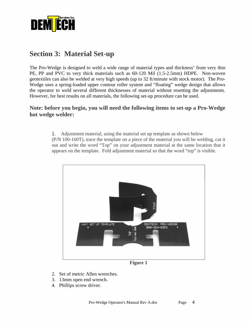
1. Adjustment material, using the material set up template as shown below (P/N 100-160T), trace the template on a piece of the material you will be welding, cut it out and write the word “Top” on your adjustment material at the same location that it appears on the template. Fold adjustment material so that the word “top” is visible.
Figure 1
2. Set of metric Allen wrenches. 3. 13mm open end wrench. 4. Phillips screw driver.
Pro-Wedge Operator's Manual Rev A.doc Page 5
Important! Unit must be cooled down before attempting adjustments.
Please refer to the parts identification photos as instructed throughout the set up procedure.
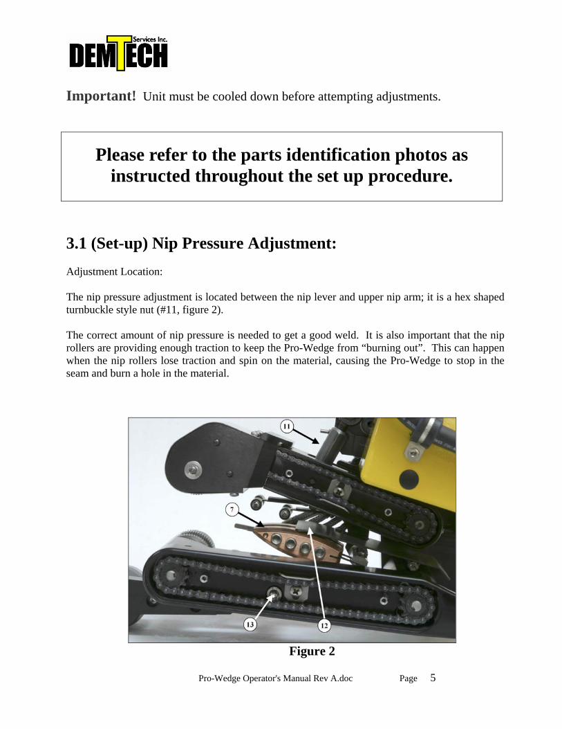
3.1 (Set-up) Nip Pressure Adjustment: Adjustment Location: The nip pressure adjustment is located between the nip lever and upper nip arm; it is a hex shaped turnbuckle style nut (#11, figure 2). The correct amount of nip pressure is needed to get a good weld. It is also important that the nip rollers are providing enough traction to keep the Pro-Wedge from “burning out”. This can happen when the nip rollers lose traction and spin on the material, causing the Pro-Wedge to stop in the seam and burn a hole in the material.
Figure 2
Pro-Wedge Operator's Manual Rev A.doc Page 6
Note: Pressure Adjustment for thin material and geotextiles:
These materials require less nip pressure. Too much pressure can cause the material to perforate material at the edge of the seam causing a “zipper” effect.
3.1.1. Make sure the heating wedge (#7, figure 2) is in the disengaged position.
3.1.2. Turn the nip pressure adjustment hex nut (#11, figure 2) clockwise while looking down from above several turns, raising the nip arm up to give a fresh starting point for this adjustment. (Loosen set screw(s) on hex nut first if present to avoid damaging threads on eye bolts) 3.1.3. Place one end, (one thickness) of your adjustment material between the nip rollers and into the unit about 1” inch. Engage nip rollers by pushing down on the nip lever until it has “clicked” into place and is held in position by the lock pin. At this point the material should move around freely between the nip rollers. 3.1.4. Turn the hex nut (#11, figure 2) counter clockwise until the nip rollers begin to pinch down on the material and you can not turn the nut by hand anymore. This zeros the adjustment. 3.1.5. Disengage nip rollers and turn the hex nut counter clockwise one full rotation. 3.1.6. Insert the adjustment material (the opposite end of the fold, two thicknesses) between the nip rollers and engage nip rollers together until the lock pin clicks into its detent as shown on next page (figure 3). Check pressure by attempting to move the material side to side. If you are able to move the material or pull the material straight out without the nip rollers turning, disengage the nip pressure and turn adjustment nut (#11, figure 2) counter clockwise ¼ turn at a time until the desired pressure is reached. Remember to tighten the set screw(s) on the adjustment nut after you have completed adjustment of the nip pressure to prevent the pressure from backing off while welding.
Pro-Wedge Operator's Manual Rev A.doc Page 7
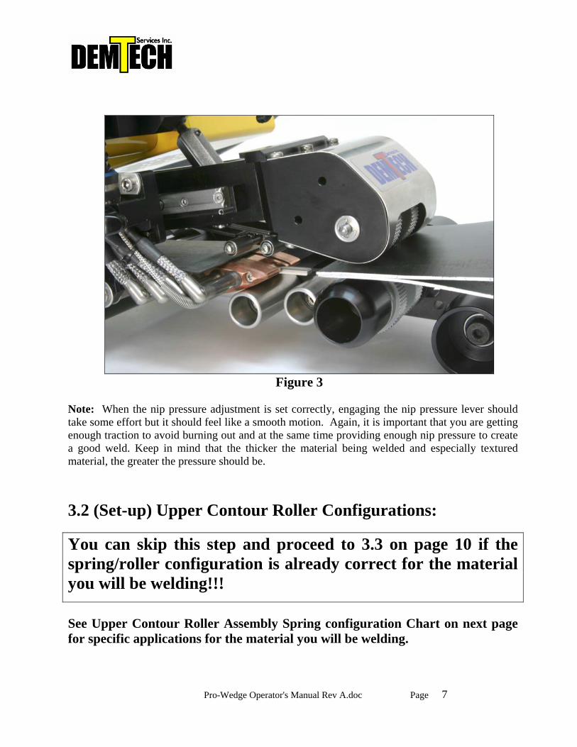
Figure 3
Note: When the nip pressure adjustment is set correctly, engaging the nip pressure lever should take some effort but it should feel like a smooth motion. Again, it is important that you are getting enough traction to avoid burning out and at the same time providing enough nip pressure to create a good weld. Keep in mind that the thicker the material being welded and especially textured material, the greater the pressure should be. 3.2 (Set-up) Upper Contour Roller Configurations:
You can skip this step and proceed to 3.3 on page 10 if the spring/roller configuration is already correct for the material you will be welding!!! See Upper Contour Roller Assembly Spring configuration Chart on next page for specific applications for the material you will be welding.
Pro-Wedge Operator's Manual Rev A.doc Page 8
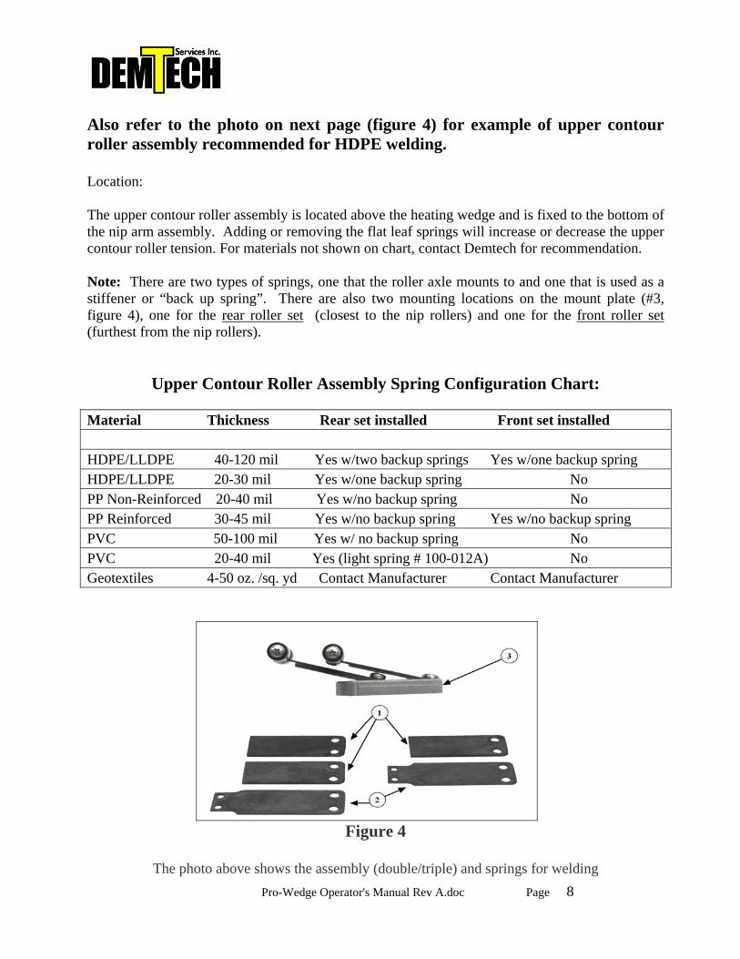
Also refer to the photo on next page (figure 4) for example of upper contour roller assembly recommended for HDPE welding. Location: The upper contour roller assembly is located above the heating wedge and is fixed to the bottom of the nip arm assembly. Adding or removing the flat leaf springs will increase or decrease the upper contour roller tension. For materials not shown on chart, contact Demtech for recommendation. Note: There are two types of springs, one that the roller axle mounts to and one that is used as a stiffener or “back up spring”. There are also two mounting locations on the mount plate (#3, figure 4), one for the rear roller set (closest to the nip rollers) and one for the front roller set (furthest from the nip rollers).
Upper Contour Roller Assembly Spring Configuration Chart:
Material Thickness Rear set installed Front set installed HDPE/LLDPE 40-120 mil Yes w/two backup springs Yes w/one backup spring HDPE/LLDPE 20-30 mil Yes w/one backup spring No PP Non-Reinforced 20-40 mil Yes w/no backup spring No PP Reinforced 30-45 mil Yes w/no backup spring Yes w/no backup spring PVC 50-100 mil Yes w/ no backup spring No PVC 20-40 mil Yes (light spring # 100-012A) No Geotextiles 4-50 oz. /sq. yd Contact Manufacturer Contact Manufacturer
Figure 4
The photo above shows the assembly (double/triple) and springs for welding
Pro-Wedge Operator's Manual Rev A.doc Page 9
40-120 mil (1.0-2.5mm) HDPE and LLDPE material. Changing spring configuration: Removing-upper contour roller assembly:
3.2.1. Remove screw from the end of the shaft that the material guide plate (# 12, figure 2, page 5) pivots on, then slide material guide off of shaft and set aside.
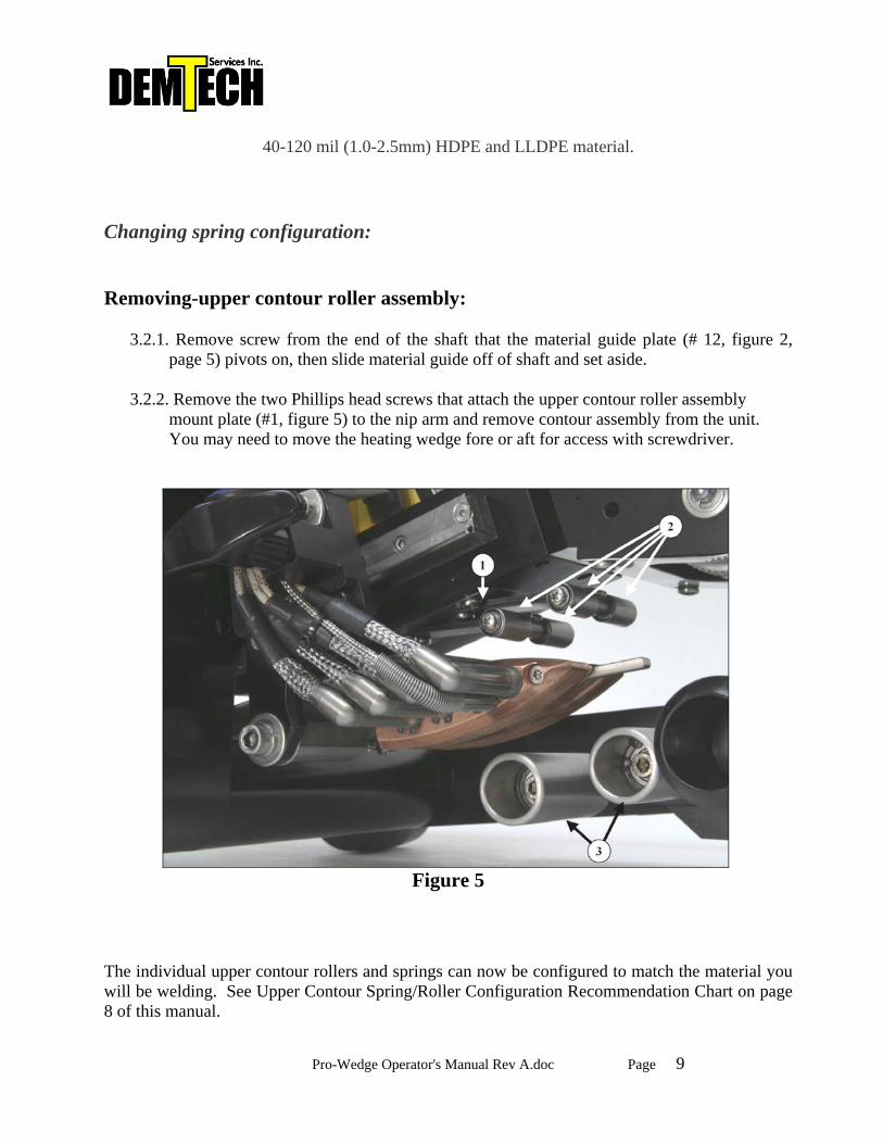
3.2.2. Remove the two Phillips head screws that attach the upper contour roller assembly
mount plate (#1, figure 5) to the nip arm and remove contour assembly from the unit. You may need to move the heating wedge fore or aft for access with screwdriver.
Figure 5
The individual upper contour rollers and springs can now be configured to match the material you will be welding. See Upper Contour Spring/Roller Configuration Recommendation Chart on page 8 of this manual.
Pro-Wedge Operator's Manual Rev A.doc Page 10
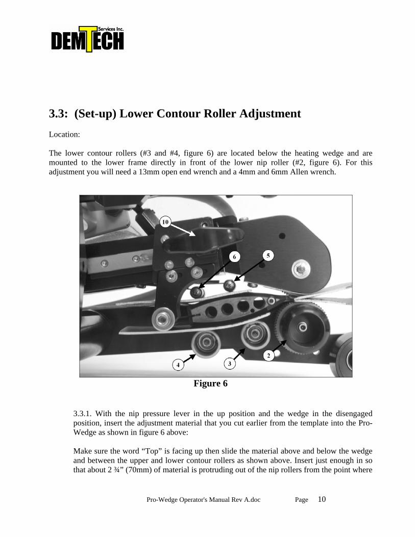
3.3: (Set-up) Lower Contour Roller Adjustment Location: The lower contour rollers (#3 and #4, figure 6) are located below the heating wedge and are mounted to the lower frame directly in front of the lower nip roller (#2, figure 6). For this adjustment you will need a 13mm open end wrench and a 4mm and 6mm Allen wrench.
Figure 6
3.3.1. With the nip pressure lever in the up position and the wedge in the disengaged position, insert the adjustment material that you cut earlier from the template into the Pro-Wedge as shown in figure 6 above: Make sure the word “Top” is facing up then slide the material above and below the wedge and between the upper and lower contour rollers as shown above. Insert just enough in so that about 2 ¾” (70mm) of material is protruding out of the nip rollers from the point where
Pro-Wedge Operator's Manual Rev A.doc Page 11
the nip rollers pinch down on the material. Slide the wedge to its engaged position until it locks into its detent then lock the nip pressure lever down on to the material.
Note 1: Make sure if using a split wedge with an air channel pin, that the notch is cut in the end of the doubled-up piece of material as it is detailed on the material template. This is to allow clearance for the air channel finger when the material set-up piece is in place.
3.3.2. With a Phillips screw driver remove lower frame chain cover to expose the lockdown bolt for the front lower contour roller (#4, figure 6). 3.3.3. Using a 6mm Allen wrench, loosen the lockdown bolt then temporarily adjust the front lower contour roller down, clockwise, away from the wedge using a 4mm Allen wrench on the end of the roller (this will give you a fresh starting point and you will make a final adjustment on this roller later). 3.3.4. Using a 13mm open end wrench, loosen the lockdown bolt (hex head) for the rear lower contour roller (#3, figure 6). You can now adjust the height of the wedge by adjusting the rear lower contour roller up or down with a 4mm Allen wrench at the end of the roller. Once the desired position has been adjusted, tighten the lockdown bolt (hex head) then check the adjustment again to make sure it did not move when tightened.
Note 2: The most important adjustment is the positioning of the wedge in relationship to the lower nip roller (#2, figure 6). The distance between the lower tip of the heating wedge and the lower nip roller should be slightly more than the thickness of the material you will be welding. The distance is set by adjusting the rear lower contour roller (#3, figure 6) up or down. Note 3: When adjusting the lower contour rollers (#4) and (#3) rotate them both to the right (counterclockwise) and up so that in their adjusted positions the rollers are closest to the nip roller (#2). Also because the rear contour roller (#3) is forcing the wedge up against the upper contour roller spring tension, you may notice the roller will still spin with your fingers. This is normal. The amount of resistance of the roller when turning it with your fingers does not matter. Note 4: The lower contour rollers are mounted to the lower frame on eccentric cams that thread onto the lockdown bolts. When adjusting, you may need to work the 4mm Allen wrench and the 6mm Allen wrench for the front contour roller (4)) or the 13mm open end wrench for the rear contour roller (3)) simultaneously to rotate the roller smoothly. Warning!
Pro-Wedge Operator's Manual Rev A.doc Page 12
If the rear lower contour roller is adjusted too high, there will not be enough clearance for the top sheet to travel through the welder and it will be pinched between the top of the heating wedge and the upper nip frame. This will result in loss of welding nip pressure and an inconsistent weld.
3.3.5. Adjust the front lower contour roller (#4, figure 6)) up and to the right (counterclockwise) until it just comes in contact with the material. The roller should have a slight amount of resistance as you rotate it. If you adjust it to tight it will rock the wedge and change the rear roller (#3) adjustment.
Note 5: If you are setting up the Pro-Wedge to weld thin material or in very hot ambient conditions the front contour roller (#4) adjustment should be set very loose or backed off completely to reduce material dwell time (over heating material) and minimize the possibility of burn outs.
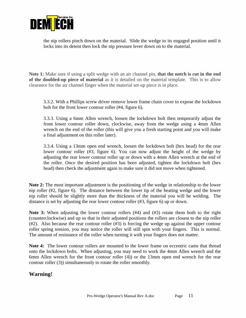
Step 4: (Set-up) Wedge Fore/Aft Adjustment The fore/aft adjustment sets the limit of travel of the heating wedge in its fully engaged position. In other words, how close the tip of the wedge is to the nip rollers. If the tip of the wedge is too close to the nip rollers they will pinch down on the wedge when pressure is engaged, reducing the amount of nip pressure on the heated material. This can also cause damage to the tip of the wedge when running out of the end of the seam. There are two types of wedge slide lock mounts, one piece (#1, figure 7) and two piece (#3, figure 7) as shown below. A two piece assembly is shown on figure 6, page 10 of this manual.
Figure 7
Pro-Wedge Operator's Manual Rev A.doc Page 13
Adjustment procedure for one piece lock mount assembly (#1, figure 7):
3.4.1. With material set-up piece in place and with nip lever and wedge engaged as shown on figure 6, page 10, use a 5mm Allen wrench to loosen the wedge mount bolt that connects the wedge hex mount to the wedge slide lock mount (#1, figure 7).
3.4.2. Move the heating wedge forward or backward (left or right) so that there is plenty of
clearance between the tip of the wedge and the upper and lower nip rollers. When adjusting Pro-Wedge for welding HDPE, position the lock bolt as far down and forward (left) in the oval adjustment slot as possible.
3.4.3. Tighten lock bolt to set adjustment.
Adjustment procedure for two piece lock mounts assembly (#3, figure 7):
3.4.4. With material set-up piece in place and with nip lever and wedge engaged as shown on figure 6, page 10, use a 5mm Allen wrench to loosen the wedge mount bolt that connects the wedge hex mount to the lock mount (#3, figure 7). For HDPE set-up, position lock bolt as far down in slot as possible and tighten bolt. 3.4.5. Using a 3mm Allen wrench, loosen the two lock screws that hold the lower piece of the assembly to the upper piece. You will need to insert the 3mm Allen wrench between the cartridge heater lead wires to access one of the screws. 3.4.6. Move the heating wedge forward or backward (left or right) so that there is plenty of clearance between the tip of the wedge and the upper and lower nip rollers. When adjusting Pro-Wedge for welding HDPE the tip of the wedge should have the same clearance as shown on figure 6 on page 10 of this manual. 3.4.7. Tighten lock screws to set adjustment. Re-check all adjustments to make sure they are correct before disengaging nip lever and wedge and removing material set-up piece.
When in doubt, contact Demtech!
(888) 324-WELD (9353) (530) 621-3200
(530) 621-0150 fax [email protected]
Pro-Wedge Operator's Manual Rev A.doc Page 14
Section 4: Welding Procedure 4.1. Power Up
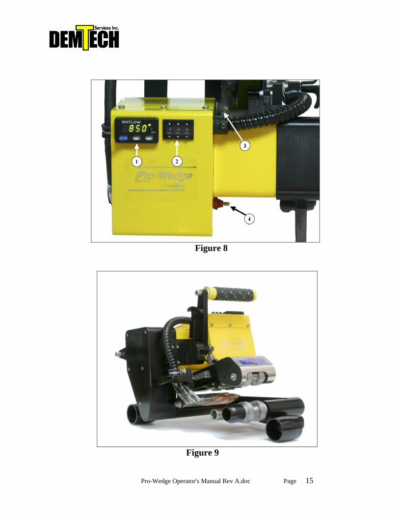
Connect the Pro-Wedge power cord to power source making sure that the voltage is correct for the model of welder you have. Please refer to pages 2 and 3 of this manual for details. Flip the main power toggle switch (#4, figure 8 on page 15) to the “on” position (up). The main power switch is located on the front of the control box, below the front handle. After a 3 second delay, the temperature control unit (#1, figure, 8) located on top of the control box should light up and display current wedge temperature. Turn on the drive motor with the motor switch (#3, figure 8), located on rear of the control box, near the nip pressure adjustment hex nut. It is recommended that the drive motor remain on at all times while the welder is plugged in. This helps eliminate hot spots on the nip rollers and makes starting a weld quicker and easier. 4.2. Setting Wedge Temperature To display current wedge temperature set point, press and hold blue “set” button located on temperature control unit. To adjust set point, press up or down arrow buttons while holding down “set” button. (Refer to Welding Speed/Temperature Setting Chart, appendix A, for recommended wedge temperature setting).
4.3. Setting Weld Speed
To set weld speed, use “+” and “-“ buttons on speed setting pot (#2, figure 8) located on top of control box, next to temperature control unit. Keep in mind that the three-digit number on the speed setting pot does not relate directly to feet or meters per minute. (Refer to the Speed Setting vs. Actual Travel Rate Chart, appendix B, for setting vs. feet per minute values).
Note: High/Low Gear Unless other wise specified, your Pro-Wedge has been factory set in low gear, which gives the welder a speed range of 0-18 feet per minute (0-5.5meters/m). You will use this range for most all in field geomembranes welding applications and especially ones that require high torque such as HDPE. The main motor drive sprockets on the Pro-wedge can be flipped to change the ratio to high gear, changing the speed range for 0-32 ft/min (0-9.5 meters/min) for high speed seaming of thin materials and non-woven geotextiles. Speed vs. setting values are listed for high and low gear in the speed-setting chart, appendix B.
Pro-Wedge Operator's Manual Rev A.doc Page 15
Figure 8
Figure 9
Pro-Wedge Operator's Manual Rev A.doc Page 16
4.4. Starting a Weld To start a weld, you must first make sure that the material to be welded is set at the proper overlap. The optimum overlap is 5-6 inches (12.7-15.2 cm) for field welds. For recommendation on in-house fabrication overlap settings, please contact the manufacturer.
Start the loading process with the nip lever in the “up” or disengaged position, the heating wedge in the “forward” or disengaged position (figure 9, page 15), and the motor on with the nip rollers turning.
First, peel back the top sheet to expose the bottom sheet. Load bottom sheet of the material into welder, between both lower contour rollers and the bottom of heating wedge, then between the two nip rollers. Second, insert the top sheet into the welder, between the upper contour roller(s) and the top of the heating wedge, and then between the nip rollers. You may need to roll the welder forward and backward a little for both sheets to settle into the welder. Third, pull out on the wedge lock handle and slide wedge toward nip rollers until the lock pin slides off the end on the slide rail. Make sure wedge is completely engaged before continuing. Fourth, engage nip rollers by pushing the nip pressure lever down until it “clicks” and is locked in position. At this time the welder should be moving and welding on its own. If the nip rollers are spinning on the material and burning a hole, quickly disengage nip rollers, roll the welder down the seam a few more inches, past the overheated area, and engage again. 4.5. Ending a Weld Just as the welder is about to run out of the end of the seam, disengage nip rollers, slide welder out of the seam, and then disengage wedge. At this time it is a good idea to tip the Pro-Wedge up onto the front handle, raising the back of the unit, to prevent a hole being melted in the material from heat radiating from the wedge.
Note: Practice makes perfect.

Pro-Wedge Operator's Manual Rev A.doc Page 17
4.6. Shut-Down
To shut down the Pro-Wedge, simply turn main power switch to the “off” position or unplug unit. After 5-10 minutes, place unit in shipping/storage case provided with welder.
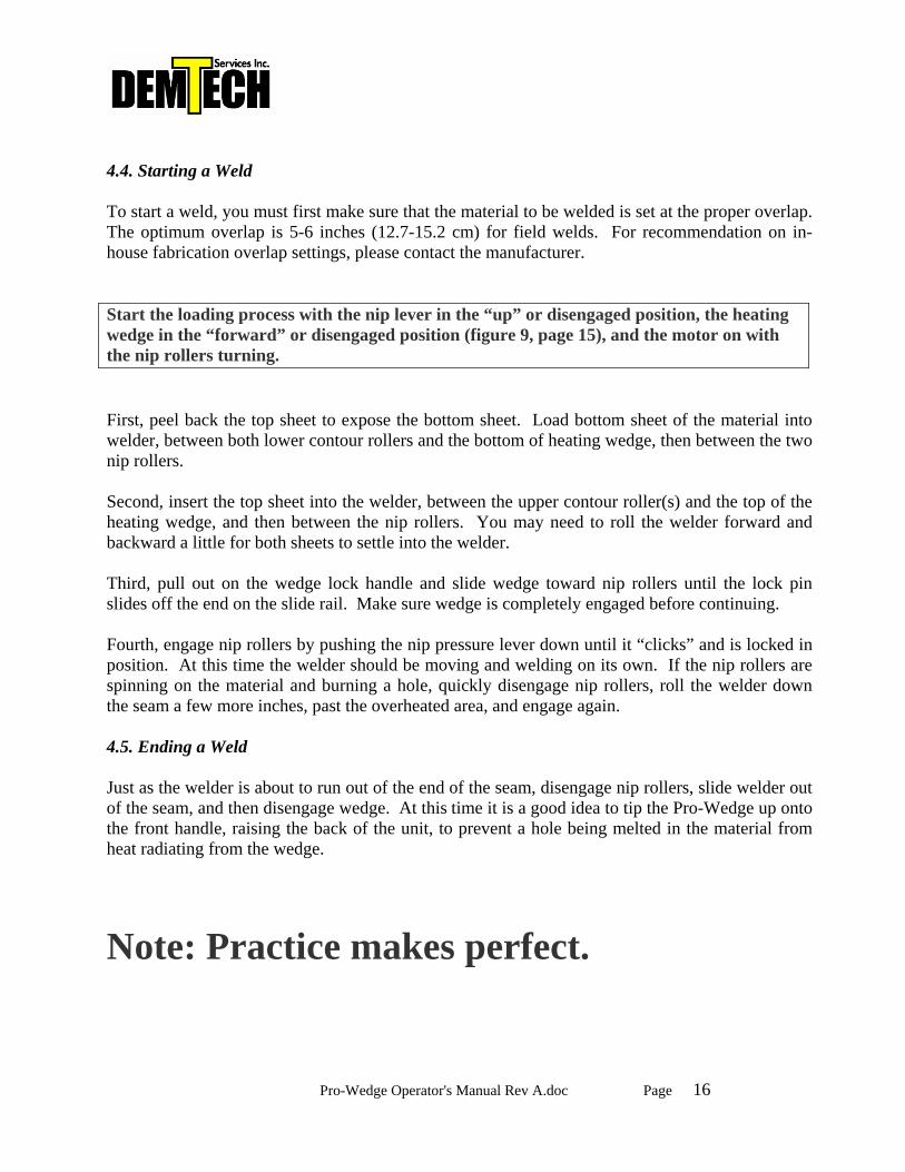
Section 5: Reference Documents (beginning after this page) 5.1 Appendix A, Welding Speed / Temperature Chart Refer to appendix A for recommended preliminary speeds and temperatures for a wide range of material types and thicknesses. This chart is a great reference tool, however all site conditions are different and the settings recommended on the chart may not be suitable for your specific site. Please contact a Demtech technical representative for advice on appropriate settings. 5.2 Appendix B, Speed Setting vs. Actual Travel Rate Chart Refer to appendix B for a chart showing the travel (welding) speed of the Pro-Wedge at various speed pot settings. Keep in mind that actual speed, especially at the highest setting (999) may vary depending on power supply, length of cords, etc. 5.3 Appendix C, Pro-Wedge Product Information Sheet Appendix B is a brochure showing photos and technical specifications of the Pro-Wedge. 5.4 Appendix D, Pro-Wedge Product Warranty 5.5 Appendix E, Pro-Wedge Spare Parts Identification Refer to spare parts identification photos and Demtech part number listings for ordering common wear item replacement parts for the Pro-Wedge.
END OF MANUAL
PRO-WEDGE WELDING SPEED / TEMPERATURE CHART
Appendix A
Material type ThicknessAmbient
TemperatureWedge
TemperatureMaximum Welding
SpeedSolid
WedgeSplit
WedgeSolid Nips
Split Nips
Upper contour rollers
HDPE 12 mil (0.3mm) 65-85 F (18-30 C) 650 F (340 C) 32 ft/min (9.8 m/min) X rubber single light upperHDPE 20 mil (0.5mm) 65-85 F (18-30 C) 750 F (400 C) 25 ft/min (7.6 m/min) X rubber single upperHDPE 30 mil (0.75mm) 65-85 F (18-30 C) 750 F (400 C) 18 ft/min (5.5 m/min) X rubber single upperHDPE 40 mil (1.0mm) 65-85 F (18-30 C) 750 F (400 C) 16 ft/min (4.9 m/min) X steel double/trippleHDPE 60 mil (1.5mm) 65-85 F (18-30 C) 860 F (460 C) 15 ft/min (4.6 m/min) X steel double/trippleHDPE 80 mil (2.0mm) 65-85 F (18-30 C) 860 F (460 C) 13 ft/min (4.0 m/min) X steel double/trippleHDPE 100mil (2.5mm) 65-85 F (18-30 C) 860 F (460 C) 12 ft/min (3.7 m/min) X steel double/trippleHDPE 120 mil (3.0mm) 65-85 F (18-30 C) 860 F (460 C) 8 ft/min (2.4 m/min) X steel double/tripple
LLDPE 20 mil (0.5mm) 65-85 F (18-30 C) 600 F (315 C) 25 ft/min (7.6 m/min) X rubber single upperLLDPE 30 mil (0.75mm) 65-85 F (18-30 C) 650 F (340 C) 22 ft/min (6.7 m/min) X rubber single upperLLDPE 40 mil (1.0mm) 65-85 F (18-30 C) 750 F (400 C) 20 ft/min (6.1 m/min) X steel single/doubleLLDPE 60 mil (1.5mm) 65-85 F (18-30 C) 800 F (425 C) 18 ft/min (5.5 m/min) X steel double/trippleLLDPE 80 mil (2.0mm) 65-85 F (18-30 C) 860 F (460 C) 15 ft/min (4.6 m/min) X steel double/tripple
Non-reinforced PVC/PP 20 mil (0.5mm) 65-85 F (18-30 C) 650 F (340 C) 25 ft/min (7.6 m/min) X X rubber single upperNon-reinforced PVC/PP 30 mil (0.75mm) 65-85 F (18-30 C) 700 F (370 C) 22 ft/min (6.7 m/min) X X rubber single upperNon-reinforced PVC/PP 40 mil (1.0mm) 65-85 F (18-30 C) 750 F (400 C) 20 ft/min (6.1 m/min) X X rubber single/doubleNon-reinforced PVC/PP 50-60 mil (1.27-1.5mm) 65-85 F (18-30 C) 800 F (425 C) 18 ft/min (5.5 m/min) X X steel steel double/trippleNon-reinforced PVC/PP 80 mil (2.0mm) 65-85 F (18-30 C) 860 F (460 C) 15 ft/min (4.6 m/min) X X steel steel double/tripple
Reinforced PP 36 mil (0.9mm) 65-85 F (18-30 C) 750 F (400 C) 32 ft/min (9.8 m/min) X steel single/singleReinforced PP 45 mil (1.1mm) 65-85 F (18-30 C) 750 F (400 C) 32 ft/min (9.8 m/min) X steel single/single
Non-woven geotextile 4 to 8 oz./sq. yd. 65-85 F (18-30 C) 650 F (340 C) 32 ft/min (9.8 m/min) X X steel steel wedge disengagedNon-woven geotextile 10 to 12 oz./sq. yd. 65-85 F (18-30 C) 650 F (340 C) 32 ft/min (9.8 m/min) X X steel steel wedge disengagedNon-woven geotextile 14 to 20 oz./sq. yd. 65-85 F (18-30 C) 650 F (340 C) 25 ft/min (7.6 m/min) X X steel steel wedge disengagedNon-woven geotextile 22 to 32 oz./sq. yd. 65-85 F (18-30 C) 650 F (340 C) 22 ft/min (6.7 m/min) X X steel steel wedge disengagedNon-woven geotextile Up to 50 oz./sq. yd. 65-85 F (18-30 C) 650 F (340 C) 18 ft/min (5.5 m/min) X X steel steel wedge disengaged
NOTE: The above parameters are intended as a basic starting point only and will need to be adjusted to compensate for each individual ambient and site condition.
Manufacturer assumes no liability for weld quality using the above parameters!!
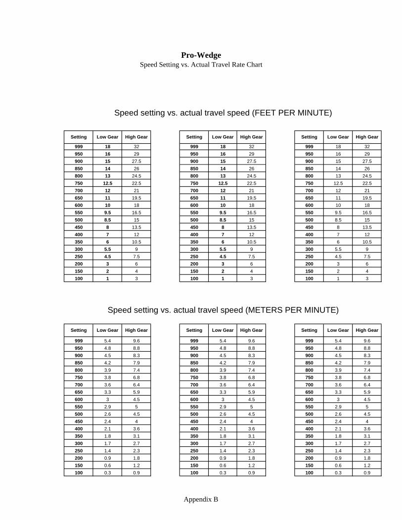
Pro-Wedge Speed Setting vs. Actual Travel Rate Chart
999 18 32 999 18 32 999 18 32950 16 29 950 16 29 950 16 29900 15 27.5 900 15 27.5 900 15 27.5850 14 26 850 14 26 850 14 26800 13 24.5 800 13 24.5 800 13 24.5750 12.5 22.5 750 12.5 22.5 750 12.5 22.5700 12 21 700 12 21 700 12 21650 11 19.5 650 11 19.5 650 11 19.5600 10 18 600 10 18 600 10 18550 9.5 16.5 550 9.5 16.5 550 9.5 16.5500 8.5 15 500 8.5 15 500 8.5 15450 8 13.5 450 8 13.5 450 8 13.5400 7 12 400 7 12 400 7 12350 6 10.5 350 6 10.5 350 6 10.5300 5.5 9 300 5.5 9 300 5.5 9250 4.5 7.5 250 4.5 7.5 250 4.5 7.5200 3 6 200 3 6 200 3 6150 2 4 150 2 4 150 2 4100 1 3 100 1 3 100 1 3
999 5.4 9.6 999 5.4 9.6 999 5.4 9.6950 4.8 8.8 950 4.8 8.8 950 4.8 8.8900 4.5 8.3 900 4.5 8.3 900 4.5 8.3850 4.2 7.9 850 4.2 7.9 850 4.2 7.9800 3.9 7.4 800 3.9 7.4 800 3.9 7.4750 3.8 6.8 750 3.8 6.8 750 3.8 6.8700 3.6 6.4 700 3.6 6.4 700 3.6 6.4650 3.3 5.9 650 3.3 5.9 650 3.3 5.9600 3 4.5 600 3 4.5 600 3 4.5550 2.9 5 550 2.9 5 550 2.9 5500 2.6 4.5 500 2.6 4.5 500 2.6 4.5450 2.4 4 450 2.4 4 450 2.4 4400 2.1 3.6 400 2.1 3.6 400 2.1 3.6350 1.8 3.1 350 1.8 3.1 350 1.8 3.1300 1.7 2.7 300 1.7 2.7 300 1.7 2.7250 1.4 2.3 250 1.4 2.3 250 1.4 2.3200 0.9 1.8 200 0.9 1.8 200 0.9 1.8150 0.6 1.2 150 0.6 1.2 150 0.6 1.2100 0.3 0.9 100 0.3 0.9 100 0.3 0.9
Speed setting vs. actual travel speed (FEET PER MINUTE)
Speed setting vs. actual travel speed (METERS PER MINUTE)
Setting Low Gear High Gear Setting Low Gear High Gear Setting Low Gear High Gear
Setting Low Gear High Gear Setting Low Gear High Gear Setting Low Gear High Gear
Appendix B
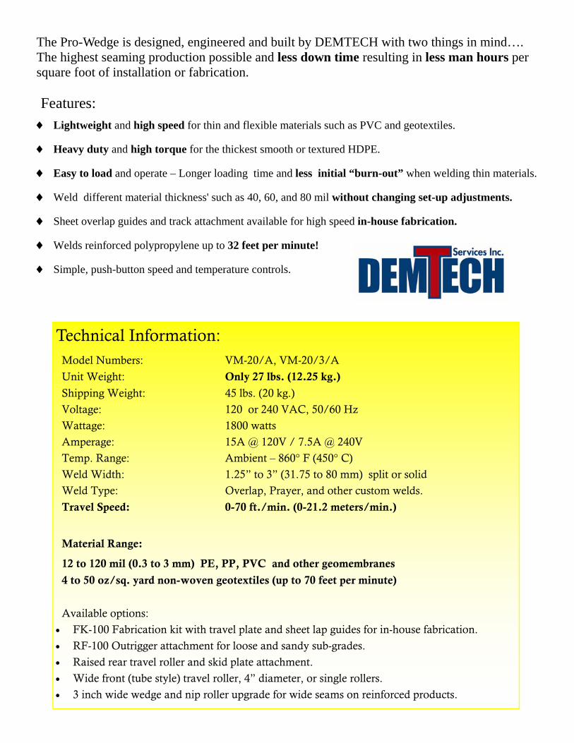
♦ Lightweight and high speed for thin and flexible materials such as PVC and geotextiles.
♦ Heavy duty and high torque for the thickest smooth or textured HDPE.
♦ Easy to load and operate – Longer loading time and less initial “burn-out” when welding thin materials.
♦ Weld different material thickness' such as 40, 60, and 80 mil without changing set-up adjustments.
♦ Sheet overlap guides and track attachment available for high speed in-house fabrication.
♦ Welds reinforced polypropylene up to 32 feet per minute!
♦ Simple, push-button speed and temperature controls.
The Pro-Wedge is designed, engineered and built by DEMTECH with two things in mind…. The highest seaming production possible and less down time resulting in less man hours per square foot of installation or fabrication.
Technical Information:
Model Numbers: VM-20/A, VM-20/3/A
Unit Weight: Only 27 lbs. (12.25 kg.)
Shipping Weight: 45 lbs. (20 kg.)
Voltage: 120 or 240 VAC, 50/60 Hz
Wattage: 1800 watts
Amperage: 15A @ 120V / 7.5A @ 240V
Temp. Range: Ambient – 860° F (450° C)
Weld Width: 1.25” to 3” (31.75 to 80 mm) split or solid
Weld Type: Overlap, Prayer, and other custom welds.
Travel Speed: 0-70 ft./min. (0-21.2 meters/min.)
Material Range:
12 to 120 mil (0.3 to 3 mm) PE, PP, PVC and other geomembranes
4 to 50 oz/sq. yard non-woven geotextiles (up to 70 feet per minute)
Available options:
• FK-100 Fabrication kit with travel plate and sheet lap guides for in-house fabrication.
• RF-100 Outrigger attachment for loose and sandy sub-grades.
• Raised rear travel roller and skid plate attachment.
• Wide front (tube style) travel roller, 4” diameter, or single rollers.
• 3 inch wide wedge and nip roller upgrade for wide seams on reinforced products.
Features:
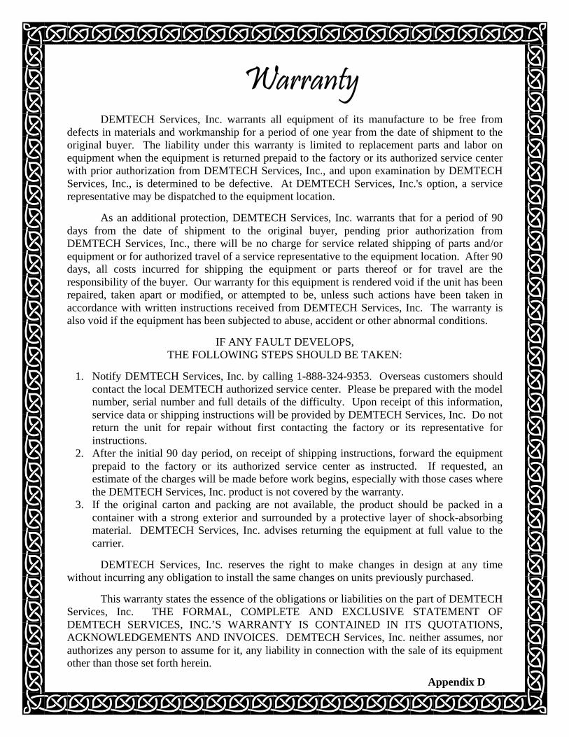
Warranty
DEMTECH Services, Inc. warrants all equipment of its manufacture to be free from defects in materials and workmanship for a period of one year from the date of shipment to the original buyer. The liability under this warranty is limited to replacement parts and labor on equipment when the equipment is returned prepaid to the factory or its authorized service center with prior authorization from DEMTECH Services, Inc., and upon examination by DEMTECH Services, Inc., is determined to be defective. At DEMTECH Services, Inc.'s option, a service representative may be dispatched to the equipment location.
As an additional protection, DEMTECH Services, Inc. warrants that for a period of 90 days from the date of shipment to the original buyer, pending prior authorization from DEMTECH Services, Inc., there will be no charge for service related shipping of parts and/or equipment or for authorized travel of a service representative to the equipment location. After 90 days, all costs incurred for shipping the equipment or parts thereof or for travel are the responsibility of the buyer. Our warranty for this equipment is rendered void if the unit has been repaired, taken apart or modified, or attempted to be, unless such actions have been taken in accordance with written instructions received from DEMTECH Services, Inc. The warranty is also void if the equipment has been subjected to abuse, accident or other abnormal conditions.
IF ANY FAULT DEVELOPS, THE FOLLOWING STEPS SHOULD BE TAKEN:
1. Notify DEMTECH Services, Inc. by calling 1-888-324-9353. Overseas customers should
contact the local DEMTECH authorized service center. Please be prepared with the model number, serial number and full details of the difficulty. Upon receipt of this information, service data or shipping instructions will be provided by DEMTECH Services, Inc. Do not return the unit for repair without first contacting the factory or its representative for instructions.
2. After the initial 90 day period, on receipt of shipping instructions, forward the equipment prepaid to the factory or its authorized service center as instructed. If requested, an estimate of the charges will be made before work begins, especially with those cases where the DEMTECH Services, Inc. product is not covered by the warranty.
3. If the original carton and packing are not available, the product should be packed in a container with a strong exterior and surrounded by a protective layer of shock-absorbing material. DEMTECH Services, Inc. advises returning the equipment at full value to the carrier.
DEMTECH Services, Inc. reserves the right to make changes in design at any time
without incurring any obligation to install the same changes on units previously purchased.
This warranty states the essence of the obligations or liabilities on the part of DEMTECH Services, Inc. THE FORMAL, COMPLETE AND EXCLUSIVE STATEMENT OF DEMTECH SERVICES, INC.’S WARRANTY IS CONTAINED IN ITS QUOTATIONS, ACKNOWLEDGEMENTS AND INVOICES. DEMTECH Services, Inc. neither assumes, nor authorizes any person to assume for it, any liability in connection with the sale of its equipment other than those set forth herein.
Appendix D
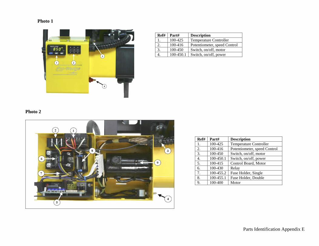
Parts Identification Appendix E
Photo 1
Photo 2
Ref# Part# Description 1. 100-425 Temperature Controller 2. 100-416 Potentiometer, speed Control 3. 100-450 Switch, on/off, motor 4. 100-450.1 Switch, on/off, power
Ref# Part# Description 1. 100-425 Temperature Controller 2. 100-416 Potentiometer, speed Control 3. 100-450 Switch, on/off, motor 4. 100-450.1 Switch, on/off, power 5. 100-415 Control Board, Motor 6. 100-430 Relay 7. 100-455.2 Fuse Holder, Single 8. 100-455.1 Fuse Holder, Double 9. 100-400 Motor
Parts Identification Appendix E
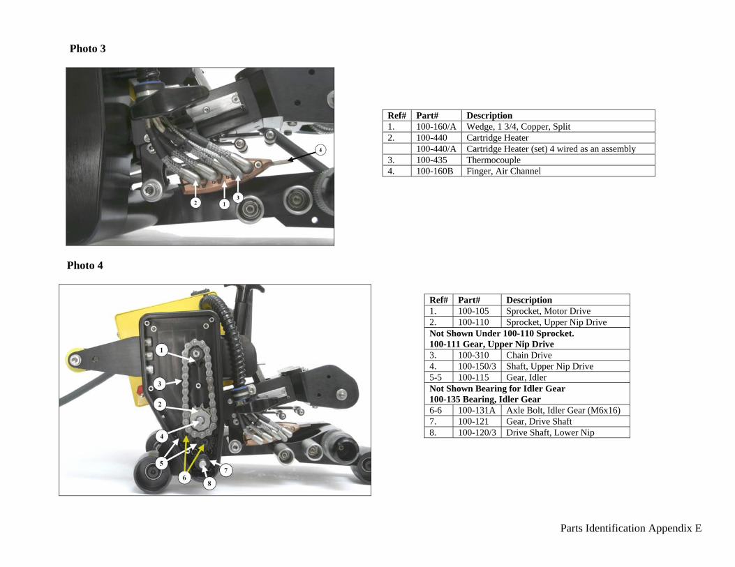
Photo 3
Photo 4
Ref# Part# Description 1. 100-160/A Wedge, 1 3/4, Copper, Split 2. 100-440 Cartridge Heater 100-440/A Cartridge Heater (set) 4 wired as an assembly 3. 100-435 Thermocouple 4. 100-160B Finger, Air Channel
Ref# Part# Description 1. 100-105 Sprocket, Motor Drive 2. 100-110 Sprocket, Upper Nip Drive Not Shown Under 100-110 Sprocket. 100-111 Gear, Upper Nip Drive 3. 100-310 Chain Drive 4. 100-150/3 Shaft, Upper Nip Drive 5-5 100-115 Gear, Idler Not Shown Bearing for Idler Gear 100-135 Bearing, Idler Gear 6-6 100-131A Axle Bolt, Idler Gear (M6x16) 7. 100-121 Gear, Drive Shaft 8. 100-120/3 Drive Shaft, Lower Nip
Parts Identification Appendix E
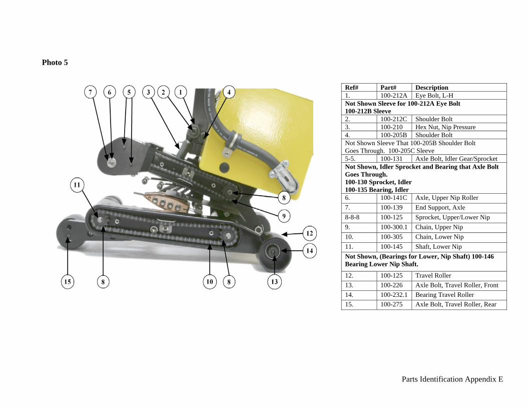
Photo 5
Ref# Part# Description 1. 100-212A Eye Bolt, L-H Not Shown Sleeve for 100-212A Eye Bolt 100-212B Sleeve 2. 100-212C Shoulder Bolt 3. 100-210 Hex Nut, Nip Pressure 4. 100-205B Shoulder Bolt Not Shown Sleeve That 100-205B Shoulder Bolt Goes Through. 100-205C Sleeve 5-5. 100-131 Axle Bolt, Idler Gear/Sprocket Not Shown, Idler Sprocket and Bearing that Axle Bolt Goes Through. 100-130 Sprocket, Idler 100-135 Bearing, Idler 6. 100-141C Axle, Upper Nip Roller 7. 100-139 End Support, Axle 8-8-8 100-125 Sprocket, Upper/Lower Nip 9. 100-300.1 Chain, Upper Nip 10. 100-305 Chain, Lower Nip 11. 100-145 Shaft, Lower Nip Not Shown, (Bearings for Lower, Nip Shaft) 100-146 Bearing Lower Nip Shaft.
12. 100-125 Travel Roller 13. 100-226 Axle Bolt, Travel Roller, Front 14. 100-232.1 Bearing Travel Roller 15. 100-275 Axle Bolt, Travel Roller, Rear
Parts Identification Appendix E
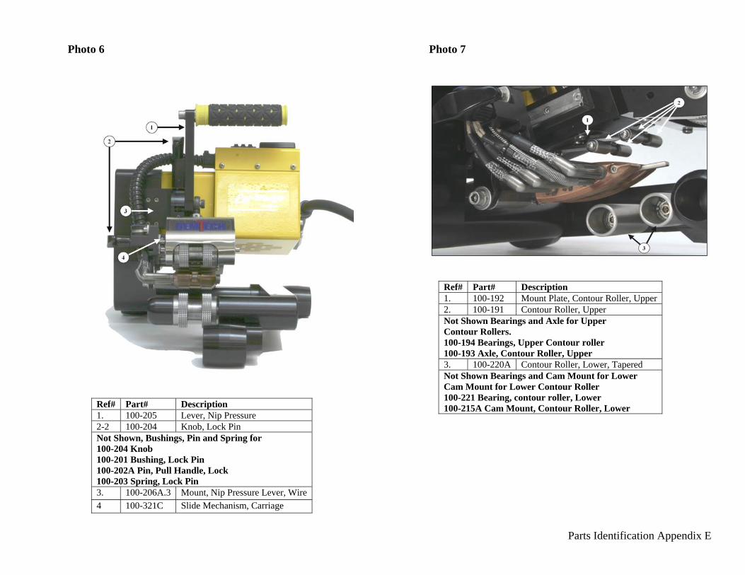
Photo 6 Photo 7
Ref# Part# Description 1. 100-192 Mount Plate, Contour Roller, Upper 2. 100-191 Contour Roller, Upper Not Shown Bearings and Axle for Upper Contour Rollers. 100-194 Bearings, Upper Contour roller 100-193 Axle, Contour Roller, Upper 3. 100-220A Contour Roller, Lower, Tapered Not Shown Bearings and Cam Mount for Lower Cam Mount for Lower Contour Roller 100-221 Bearing, contour roller, Lower 100-215A Cam Mount, Contour Roller, Lower Ref# Part# Description
1. 100-205 Lever, Nip Pressure 2-2 100-204 Knob, Lock Pin Not Shown, Bushings, Pin and Spring for 100-204 Knob 100-201 Bushing, Lock Pin 100-202A Pin, Pull Handle, Lock 100-203 Spring, Lock Pin 3. 100-206A.3 Mount, Nip Pressure Lever, Wire 4 100-321C Slide Mechanism, Carriage

Parts Identification Appendix E
Photo 8 Photo 9
Ref# Part# Description 1. 100-010 Backup Spring, Contour Roller Upper 2. 100-012 Spring w/Mount Contour Roller Upper 3. 100-192 Mount Plate, Contour Roller Upper
Ref# Part# Description 1. 100-200 Lock Mount, Wedge Slide (One Piece) 2. 100-200L Lock Mount, Wedge Slide (Lower Piece) 3. 100-200U Lock Mount, Wedge Slide (Upper Piece)


![CICADA - USENIX · 1 vm 2 vm 3 vm 4 vm 5vm 6 vm 7 vm 8 vm 9 vm 2 vm 3 vm 4 vm 5 vm 6 vm 7 vm 8 vm 9 vm 1 rigid application (similar to VOC [1]) vm 1 vm 2 vm 3 vm 4 vm 5vm 6 vm 7 vm](https://img.pdfslide.net/doc/110x75/5f3ade2be7477529602b0cb3/cicada-usenix-1-vm-2-vm-3-vm-4-vm-5vm-6-vm-7-vm-8-vm-9-vm-2-vm-3-vm-4-vm-5-vm.jpg)