Embed Size (px)
Citation preview
c.3
SANDIA REPORTSAND96-8564 ● UC–1 409Unlimited ReleasePrinted October 1996
Proceedings of theInternational Workshop onMeasurement and Computationof Turbulent Nonpremixed Flames
Edited byRobert S. Barlow
●
Issued by Sandia National Laboratories, operated for the United StatesDepartment of Energy by Sandia Corporation.NOTICE This report was prepared as an account of work sponsored byan a9encY Of the United States Government. Neither the United StatesGovernment nor any agency thereof, nor any of their employees, nor anyof the contractors, subcontractors, or their employees, makes any war.rarity, express or implied, or assumes any legal liability or responsibilityfor the accuracy, completeness, or usefulness of any information,
aPParatus, Product, or Process disclosed, or represents that its usewould not infringe privately owned rights. Reference herein to anyspecific commercial product, process, or service by trade name,trademark, manufacturer, or otherwise, does not necessarily constituteor imply its endorsement, recommendation, or favoring by the UnitedStates Government, any agency thereof or any of their contractors orsubcontractors. The views and opinions expressed herein do notnecessarily state or reflect those of the United States Government, anyagency thereof or any of their contractors or subcontractors.
This report has been reproduced from the best available copy.
Available to DOE and DOE contractors from:
Office of Scientific and Technical InformationP. 0. BOX 62Oak Ridge, TN 37831
Prices available from (61 5) 576-8401, FTS 626-8401
Available to the public from:
.National Technical Information ServiceU.S. Department of Commerce5285 Port Royal Rd.Springfield, VA 22161
-..—.
UC-1409
SAND96-8564Unlimited Release
Printed October 1996
PROCEEDINGS OF THEINTERNATIONAL WORKSHOP ON
MEASUREMENT AND COMPUTATION OFTURBULENT NONPREMIXED FLAMES
Naples, ItalyJuly 26-27, 1996
Edited byRobert S. Barlow
Sandia National Laboratories, Livermore, CA 94551
ABSTRACT
This SAND report documents the proceedings of the International Workshop on Measurementand Computation of Turbulent Nonpremixed Flames, held in Naples, Italy on July 26-27,1996. Contents include materials that were distributed to participants at the beginning of theworkshop, as well as a Summary of Workshop Accomplishments that was generated at theclose to this Naples meeting.
The Naples workshop involved sixty-one people from eleven countries. The primaryobjectives were: i) to select a set of well-documented and relatively simple flames that wouldbe appropriate for collaborative comparisons of model predictions; and ii) to specify commonsubmodels to be used in these predictions, such that models for the coupling of turbulence andchemistry might be isolated and better understood.
These proceedings are also “published” on the Web and those interested in the ongoing processof data selection and model comparison should consult the workshop page for the most recentand complete information on these collaborative research efforts. The URL is:
(http://www/ca.sandia.gov/tdf/Workshop.html)
‘ Correspondence should be addressed to [email protected]
3/4

Blank Page
.
.%
International Workshop on Measurement and Computationof Turbulent Nonpremixed Flames
Naples, ItalyJuly 26-27, 1996
Organizing Committee: R. Barlow, R. Bilger, J.-Y. Chen, I. Gökalp, E. Hassel, A. Masri, N. Peters
Contents
Preface and Objectives . . . . . . . . . . . . . . . . . . . . . . . . . . . . . . . . . . . . . . . . . . . . . . . . . . . . . . . . . . . . . . . . . . . . . . . . . . . . . . .7
Agenda . . . . . . . . . . . . . . . . . . . . . . . . . . . . . . . . . . . . . . . . . . . . . . . . . . . . . . . . . . . . . . . . . . . . . . . . . . . . . . . . . . . . . . . . . . . . . . . . .8
Discussion Issues . . . . . . . . . . . . . . . . . . . . . . . . . . . . . . . . . . . . . . . . . . . . . . . . . . . . . . . . . . . . . . . . . . . . . . . . . . . . . . . . . . . 10
Questionnaire Results . . . . . . . . . . . . . . . . . . . . . . . . . . . . . . . . . . . . . . . . . . . . . . . . . . . . . . . . . . . . . . . . . . . . . . . . . . . . . . 12
Overview of Some Available Data Sets . . . . . . . . . . . . . . . . . . . . . . . . . . . . . . . . . . . . . . . . . . . . . . . . . . . . . . . . . . 14
Data Summaries:
TH Darmstadt H2/N2 Jet Flames . . . . . . . . . . . . . . . . . . . . . . . . . . . . . . . . . . . . . . . . . . . . . . . . . . . . . . . . . . . . . 15
DLR Stuttgart H2/N2 Jet Flames . . . . . . . . . . . . . . . . . . . . . . . . . . . . . . . . . . . . . . . . . . . . . . . . . . . . . . . . . . . . . 17
Sandia H2/He Jet Flames . . . . . . . . . . . . . . . . . . . . . . . . . . . . . . . . . . . . . . . . . . . . . . . . . . . . . . . . . . . . . . . . . . . . . . 21
ETH Zurich H2/He Jet Flames . . . . . . . . . . . . . . . . . . . . . . . . . . . . . . . . . . . . . . . . . . . . . . . . . . . . . . . . . . . . ...23
Univ. Dayton H2 Jet Flames and Air Jets . . . . . . . . . . . . . . . . . . . . . . . . . . . . . . . . . . . . . . . . . . . . . . . . ...27
Sandia CO/H2/N2 Jet Flames . . . . . . . . . . . . . . . . . . . . . . . . . . . . . . . . . . . . . . . . . . . . . . . . . . . . . . . . . . . . . . . . . 35
TU Delft Piloted Natural Gas Flames . . . . . . . . . . . . . . . . . . . . . . . . . . . . . . . . . . . . . . . . . . . . . . . . . . . . . . . . 37
U Sydney/Sandia Piloted Flames . . . . . . . . . . . . . . . . . . . . . . . . . . . . . . . . . . . . . . . . . . . . . . . . . . . . . . . . . . . . . 41
U Sydney/Sandia Bluff-Body Flames . . . . . . . . . . . . . . . . . . . . . . . . . . . . . . . . . . . . . . . . . . . . . . . . . . . . . . . 47
List of Participants . . . . . . . . . . . . . . . . . . . . . . . . . . . . . . . . . . . . . . . . . . . . . . . . . . . . . . . . . . . . . . . . . . . . . . . . . . . . . . . ...53
Summary of Workshop Accomplishments . . . . . . . . . . . . . . . . . . . . . . . . . . . . . . . . . . . . . . . . . . . . . . . . . . . . . . 61
5/6

Blank Page
*
International Workshop on Measurement and Computationof Turbulent Nonpremixed Flames
Preface and Objectives
In recent years, there has been important progress in both experimental and computationalresearch on turbulent nonpremixed combustion. We wish to consolidate some aspects of thisprogress by identifying a set of well-documented and relatively simple flames that can serve asbenchmark cases for comparison with model predictions.
The emphasis of this workshop is on fundamental issues of turbulence-chemistry interactions ingaseous, non-sooting flames. The data sets under consideration include simple jet flames, pilotedjet flames, and bluff-body stabilized flames. This emphasis is complementary to othercollaborative efforts involving more technical flames.
An important objective of the workshop and subsequent collaborations will be to isolatesubmodels that treat mixing and reaction. To accomplish this it will be necessary to eliminate,minimize, or at least try to understand the differences in model predictions that result from usingdifferent chemical mechanisms, different fluid dynamics models, different model constants,different numerical schemes, different thermo-fluid properties, or different radiation models.
This will not be a competition to identify the model that best matches the data, since a model mayget the right answers for the wrong reasons. Rather, this is intended as a collaborative exercise tobetter understand the critical issues in the measurement and modeling of turbulence-chemistryinteractions. We want to identify priorities for additional experiments and pathways for potentialimprovements in a variety of combustion models.
Specific objectives of this workshop are to:
● Select a set of well-documented flames that are appropriate for collaborative comparisonof model predictions.
● Determine a process for review and expansion of this collective data base.
● Identify gaps in the existing data base and, if possible, establish priorities and a time tablefor filling these gaps.
● Establish common submodels, where appropriate, to simplify the task of comparingmodel predictions.
● Define ground rules for comparison of model predictions.
Identify an appropriate format for presentation and publication of the results of thesecollaborative comparisons.
Progress toward these objectives will be documented and distributed at the end of the workshopor during the Symposium week. Workshop results and information on subsequent collaborationswill also be published on the Web at:
http://www.ca.sandia.gov/tdf/Workshop.html
7
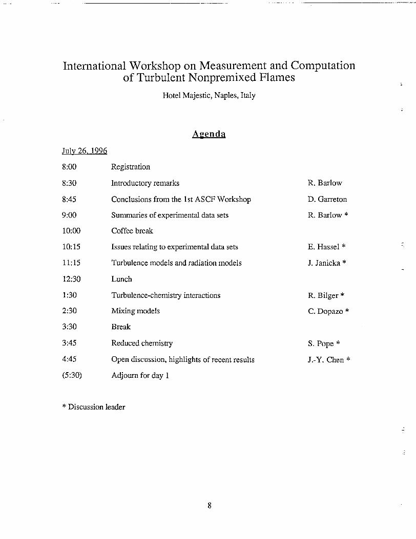
International Workshop on Measurement and Computationof Turbulent Nonpremixed Flames
Hotel Majestic, Naples, Italy
~UIV 26.1996
8:00 Registration
8:30 Introductory remarks
8:45 Conclusions from the 1st ASCF Workshop
9:00 Summaries of experimental data sets
10:00 Coffee break
10:15
11:15
12:30
1:30
2:30
3:30
3:45
4:45
(5:30)
Issues relating to experimental data sets
Turbulence models and radiation models
Lunch
Turbulence-chemistry interactions
Mixing models
Break
Reduced chemistry
Open discussion, highlights of recent results
Adjourn for day 1
R. Barlow
D. Garreton
R. Barlow *
E, Hassel *
J. Janicka *
R. Bilger *
C. Dopazo *
S. Pope *
J.-Y. Chen *
* Discussion leader
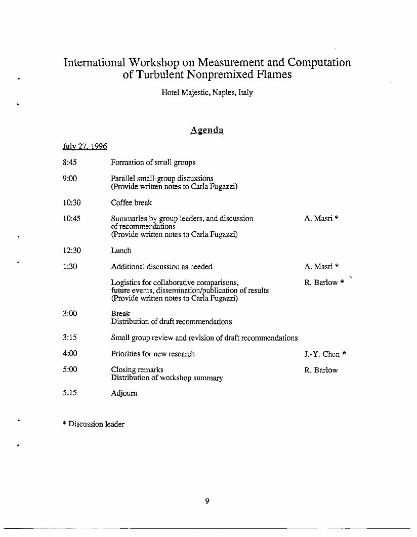
International Workshop on Measurement and Computationof Turbulent Nonpremixed Flames
Hotel Majestic, Naples, Italy
A~enda
July 27.1996
8:45 Formation of small groups
9:00 Parallel small-group discussions(Provide written notes to Carla Fugazzi)
10:30 Coffee break
10:45 Summaries by group leaders, and discussionof recommendations(Provide written notes to Carla Fugazzi)
A. Masri *
12:30 Lunch
1:30 Additional discussion as needed A. Masn *.
Logistics for collaborative comparisons, R. Ba.rlow * ‘future events, dissemination/publication of results(Provide written notes to Carla Fugazzi)
3:00 BreakDistribution of draft recommendations
3:15 Small group review and revision of draft recommendations
4:00 Priorities for new research J.-Y. Chen *
5:00 Closing remarks R. BarlowDistribution of workshop summary
5:15 Adjourn
* Discussion leader
9
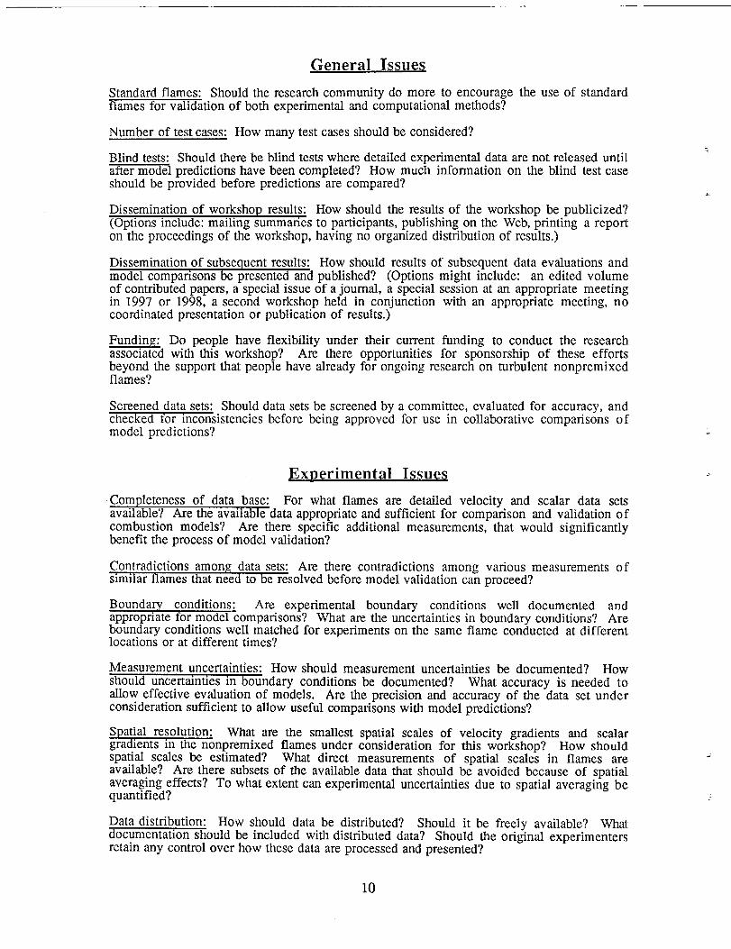
General Issues
Standard flames: Should the research community do more to encourage the use of standardflames for validation of both experimental and computational methods?
Number of test cases: How many test cases should be considered?
Blind tests: Should there be blind tests where detailed experimental data are not released untilafter model predictions have been completed? How much information on the blind test caseshould be provided before predictions are compared?
Dissemination of workshop results: How should the results of the workshop be publicized?(Options include: mailing summaries to participants, publishing on the Web, printing a reporton the proceedings of the workshop, having no organized distribution of results.)
Dissemination of subsequent results: How should results of subsequent data evaluations andmodel comparisons be presented and published? (Options might include: an edited volumeof contributed papem a special issue of a journal, a special session at an appropriate meetingin 1997 or 1998, a second workshop held in conjunction with an appropriate meeting, nocoordinated presentation or publication of results.)
Funding: Do people have flexibility under their current funding to conduct the researchassociated with thk workshop? Are there opportunities for sponsorship of these effortsbeyond the support that people have already for ongoing research on turbulent nonpremixedflames?
Screened data sets: Should data sets be screened by a committee, evaluated for accuracy, andchecked for inconsistencies before being approved for use in collaborative comparisons ofmodel predictions?
Ex~erirnental Issues
Completeness of data base: For what flames are detailed velocity and scalar data setsavailable? Are the available data appropriate and sufficient for comparison and validation ofcombustion models? Are there specific additional measurements, that would significantlybenefit the process of model validation?
Contradictions among data sets: Are there contradictions among various measurements ofslmdar flames that need to be resolved before model validation can proceed?
Boundary conditions: Are experimental boundary conditions well documented andappropriate for model comparisons? What are the uncertainties in boundary conditions? Areboundary conditions well matched for experiments on the same flame conducted at differentlocations or at different times?
Measurement uncertainties: How should measurement uncertainties be documented? Howshould uncertainties in boundary conditions be documented? What accuracy is needed toallow effective evaluation of models. Are the precision and accuracy of the data set underconsideration sufficient to allow useful comparisons with model predictions?
Spatial resolution: What are the smallest spatial scales of velocity gradients and scalargradients in the nonpremixed flames under consideration for this workshop? How shouldspatial scales be estimated? What direct measurements of spatial scales in flames areavailable? Are there subsets of the available data that should be avoided because of spatialaveraging effects? To what extent can experimental uncertainties due to spatial averaging bequantified?
-.
.,
.
-.
.-
Data distribution: How should data be distributed? Should it be freely available? Whatdocumentation should be included with distributed data? Should the original experimentersretain any control over how these data are processed and presented?
10
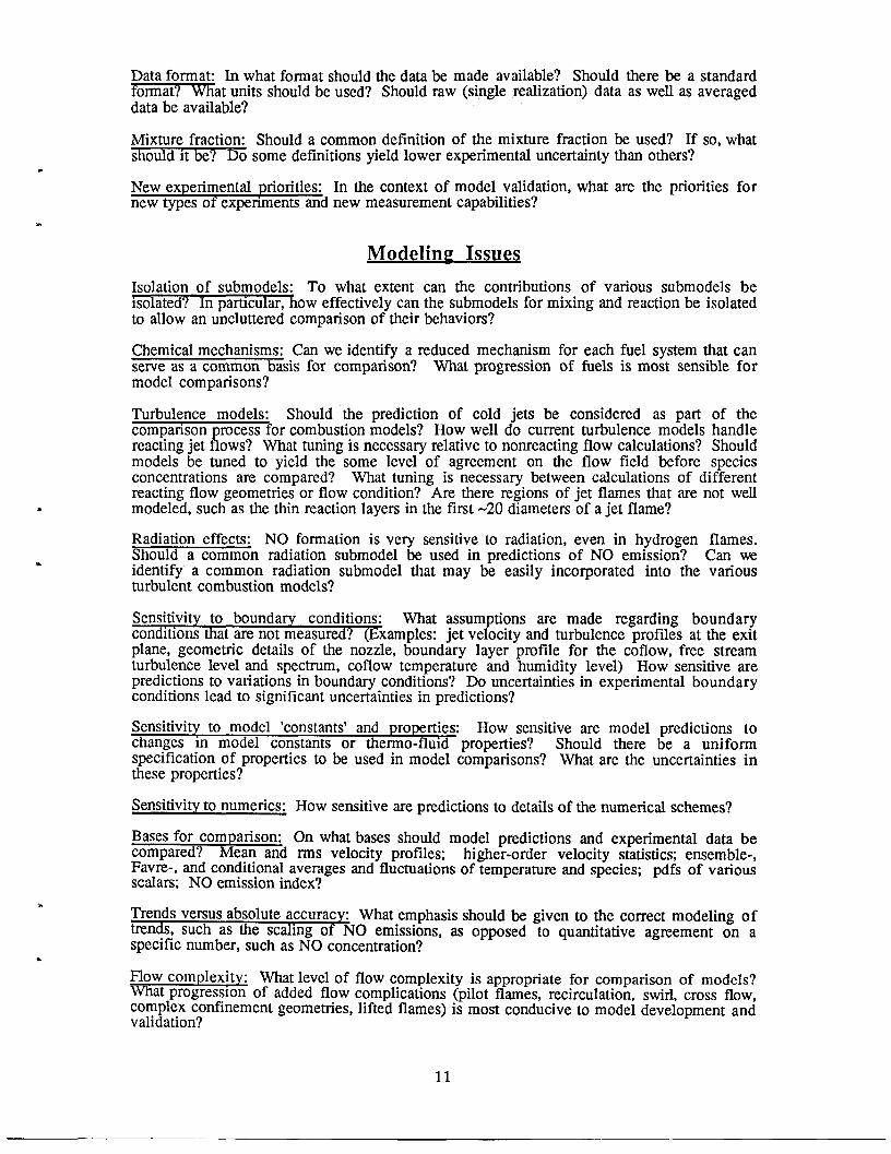
Data format: In what format should the data be made available? Should there be a standard~ormat? What units should be used? Should raw (single realization) data as well as averageddata be available?
Mixture fraction: Should a common definition of the mixture fraction be used? If so, whatshould It be? Do some definitions yield lower experimental uncertainty than others?
New experimental priorities: In the context of model validation, what are the priorities fornew types of experiments and new measurement capabilities?
.
Modelin~ Issues
Isolation of submodels: To what extent can the contributions of various submodels beisolated? In pamcular, how effectively can the submodels for mixing and reaction be isolatedto allow an uncluttered comparison of their behaviors?
Chemical mechanisms: Can we identify a reduced mechanism for each fuel system that canserve as a common basis for comparison? What progression of fhels is most sensible formodel comparisons?
Turbulence models: Should the prediction of cold jets be considered as part of thecomparison process for combustion models? How well do current turbulence models handlereacting jet flows? What tuning is necessary relative to nonreacting flow calculations? Shouldmodels be tuned to yield the some level of agreement on the flow field before speciesconcentrations are compared? What tuning is necessary between calculations of differentreacting flow geometries or flow condition? Are there regions of jet flames that are not wellmodeled, such as the tlin reaction layers in the first -20 diameters of a jet flame?
Radiation effects: NO formation is very sensitive to radiation, even in hydrogen flames.Should a common radiation submodel be used in predictions of NO emission? Can weidentify a common radiation submodel that may be easily incorporated into the variousturbulent combustion models?
Sensitivity to boundary conditions: What assumptions are made regarding boundarycondmons that are not measured? (Examples: jet velocity and turbulence profiles at the exitplane, geometric details of the nozzle, boundary layer profile for the coflow, free streamturbulence level and spectrum, coflow temperature and humidity level) How sensitive arepredictions to variations in boundary conditions? Do uncertainties in experimental boundaryconditions lead to significant uncertainties in predictions?
Sensitivity to model ‘constants’ and properties: How sensitive are model predictions tochanges m model constants or thermo-fluld properties? Should there be a uniformspecification of properties to be used in model comparisons? What are the uncertainties inthese properties?
Sensitivity to numerics: How sensitive are predictions to details of the numerical schemes?
Bases for comparison: On what bases should model predictions and experimental data becompared? Mean and rms velocity profiles; higher-order velocity statistics; ensemble-,Favre-, and conditional averages and fluctuations of temperature and species; pdfs of variousscalars; NO emission index?
Trends versus absolute accuracy: What emphasis should be given to the correct modeling oftrends, such as the scaling of NO emissions, as opposed to quantitative agreement on aspecific number, such as NO concentration?
Flow complexity: What level of flow complexity is appropriate for comparison of models?What progression of added flow complications (pilot flames, recirculation, swirl, cross flow,complex confhement geometries, lifted flames) is most conducive to model development andvalidation?
11
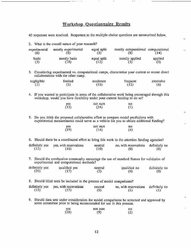
Worksho~ 0 uestionnaire Results
40responses were received. Responses to the multiple-choice questions are summarized below.
2. What is the overall nature of your research?
experimental mostly experimental equal split(6) (8) (3)
basic mostly basic equal split(3) (18) (12)
3. Considering experimental vs. computational camps,collaborations with the other camp.
negligible limited moderate
4.
5.
6.
“(1) (5) (15)
mostly computational(8)
mostly applied(3)
computational(14)
applied(o)
characterize your current or recent direct
frequent extensive(12) (6)
If you wanted to participate in some of the collaborative work being encouraged through thisworkshop, would you have flexibility under your current funding to do so?
yes not sure(13) (24) ?;
Do you think the proposed collaborative effort to compare model predictions withexperimental measurements could serve as a vehicle for you to obtain additional funding?
yes not sure(19) (14) ?;
Should there be a coordinated effort to bring thk work to the attention funding agencies?
definitely yes yes, with reservations neutral no, with reservations definitely no(12) (16) (lo) (o) (o)
7. Should the combustion community encourage the use of standard flames for validation ofexperimental and computational methods?
definitely yes qualified yes neutral qualified no definitely no(20) (17) (2) (o) (o)
8. Should blind tests be included in the process of model comparisons?
defi$~~ yes yes, with reservations neutral no, with reservations definitely no(17) (9) (1) (1)
-..9. Should data sets under consideration for model comparisons be screened and approved by
some committee prior to being recommended for use in this process.
yes not sure(28) (9) :!
12
.-
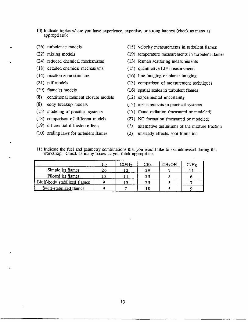
10) Indicate topics where you have experience, expertise, or strong interest (check as many as
*
.
.
appropriate):
(26)
(22)
(24)
(18)
(14)
(21)
(19)
(8)
(8)
(15)
(18)
(19)
(lo)
turbulence models
mixing models
reduced chemical mechanisms
detailed chemical mechanisms
reaction zone structure
pdf models
flamelet models
conditional moment closure models
eddy breakup models
modeling of practical systems
comparison of different models
differential diffusion effects
scaling laws for turbulent flames
(15)
(19)
(13)
(15)
(16)
(13)
(16)
(12)
(13)
(17)
(27)
(7)
(2)
velocity measurements in turbulent flames
temperature measurements in turbulent flames
Raman scattering measurements
quantitative LIF measurements
line imaging or planar imaging
comparison of measurement techniques
spatial scales in turbulent flames
experimental uncertainty
measurements in practical systems
flame radiation (measured or modeled)
NO formation (measured or modeled)
alternative definitions of the mixture fraction
unsteady effects, soot formation
11) Indicate the fuel and geometry combinations that vou would like to see addressed during thkworkshop. Check as hany b~xes as you think apfiropnate.
H?, Co/H?< cm CH?OH C~H~Simple iet flames 26 12 29 7 11Piloted iet flames 13 11 23 5 6
Bluff-body stabilized flames 9 13 23 5 7Swirl-stabilized flames 9 7 18 5 9
.
.
13
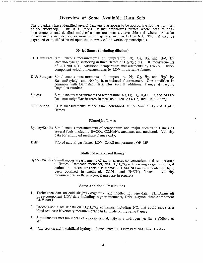
overview of Some Available Data Sets
The organizers have identified several data sets that appear to be appropriate for the purposesof the workshop. This is a limited list that emphasizes flames where both velocitymeasurements and detailed multi scalar measurements are available and where the scalarmeasurements include one or more minor species, such as OH or NO. The list may beexpanded or modified based upon the interests of the workshop participants.
TH Darmstadt
DLR-Stuttgart
Sandia
ETH Zurich
Sydney/Sandia
Delft.
Sydney/Sandia
1.
2.
3.
4.
Hz jet flames (including dilution)
Simultaneous measurements of temperature, N2, 02,Raman/Rayleigh scattering in three flames of H2/N2 (1:1).of OH and NO. Additional temperature measurements
H2, and H20 byLIF measurements
by CARS. Three-component velocity measurements-by LDV in the same flam”es.
Simultaneous measurements of temperature, N2, 02, H2, and H20 byRaman/Rayleigh and NO by laser-induced fluorescence. One condition incommon with Darmstadt data, plus several additional flames at varyingReynolds number.
Simultaneous measurements of temperature, N2, 02, H2, H20, OH, and NO byRaman/Raleigh/LIF in three flames (undiluted, 20% He, 40% He dilution)
LDV measurements at the same conditions as the Sandia H2 and H~eflames.
Piloted jet flames
Simultaneous measurements of temperature and major species in flames ofseveral fuels, including H~C02, CO/H~2, methane, and methanol. Velocitydata for undiluted methane flames only.
Piloted natural gas flame. LDV, CARS temperatures, OH LIF
Bluff-body-stabilized flames
Simultaneous measurements of major species concentrations and temperaturein flames of methane, methanol, and CO/HflZ with varying degrees on localextinction. Recent data sets also include OH and NO measurements and havebeen obtained in methanol, COlH2, and HflCH4 flames. Velocitymeasurements in these recent flames are in progress.
Some Additional Possibilities
Turbulence data on cold air jets (Wimanski and Fledler hot wire data, TH Darmstadtthree-component LDV data including- higher moments, Univ. Dayton three-componentLDV data)
Recent Sandia scalar data on CO/H~2 jet flames, including NO, that could serve as ablind test case if velocity measurements can be made on the same flames
Simultaneous measurements of velocity and density in a hydrogen jet flame (Dibble etal).
Data sets on swirl-stabilized hydrogen flames from TH Darmstadt and Univ. Dayton.
14
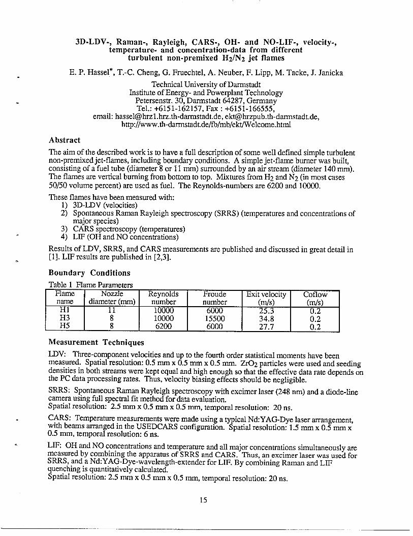
3D-LDV-, Raman-, Rayleigh, CARS-, OH- and NO-LIF-, velocity-,temperature- and concentration-data from different
turbulent non-premixed H2/N2 jet flames
E. P. Hassel*, T.-C. Cheng, G. Fruechtel, A. Neuber, F. Lipp, M. Tacke, J. Janicka
Technical University of DarmstadtInstitute of Energy- and PowerPlant Technology
Petersenstr. 30, Darmstadt 64287, GermanyTel.: +6151-162157, Fax : +6151-166555,
email: [email protected]. th-da.rmstadt.de, [email protected]. de,http://www.th-darrnstadt.de/fb/mb/ekt/Welcome.html
Abstract
The aim of the described work is to have a full description of some well defined simple turbulentnon-premixed jet-flames, including boundary conditions. A simple jet-flame burner was built,consisting of a fuel tube (diameter 8 or 11 mm) surrounded by an air stream (diameter 140 mm).The flames are vertical burning from bottom to top. Mixtures from H2 and N2 (in most cases50/50 volume percent) are used as fuel. The Reynolds-numbers are 6200 and 10000.
These flames have been measured with:1) 3D-LDV (velocities)2) Spontaneous Raman Rayleigh spectroscopy (SRRS) (temperatures and concentrations of
major species)3) CARS spectroscopy (temperatures)
* 4) LIF (OH and NO concentrations)
Results of LDV, SRRS, and CARS measurements are published and discussed in great detail in[1]. LIF results are published in [2,3].s
Boundary Conditions
Table 1 Flame PmametersFlame Nozzle Reynolds Froude Exit velocity Coflowname diameter (mm) number number (m/s) (m/s)HI 11 10000 6000 25.3H3 8 10000 15500 34.8 $;H5 8 6200 6000 27.7 0.2
Measurement Techniques
LDV Three-component velocities and up to the fourth order statistical moments have beenmeasured. Spatial resolution: 0.5 mm x 0.5 mm x 0.5 mm. Zr02 particles were used and seedingdensities in both streams were kept equal and high enough so that the effective data rate depends onthe PC data processing rates. Thus, velocity biasing effects should be negligible.
SRRS: Spontaneous Raman Rayleigh spectroscopy with excimer laser (248 nm) and a diode-linecamera using full spectral fit method for data evaluation.Spatial resolution: 2.5 mm x 0,5 mm x 0.5 mm, temporal resolution: 20 ns.
* CARS: Temperature measurements were made using a typical Nd:YAG-Dye laser arrangement,with beams arranged in the USEDCARS configuration. Spatial resolution: 1.5 mm x 0.5 mm x0.5 mm, temporal resolution: 6 ns.
. LE OH and NO concentrations and temperature and all major concentrations simultaneously aremeasured by combining the apparatus of SRRS and CARS. Thus, an excimer laser was used forSRRS, and a Nd:YAG-Dye-wavelength-extender for LIF. By combining Raman and LIFquenching is quantitatively calculated.Spatial resolution: 2.5 mm x 0.5 mm x 0.5 mm, temporal resolution: 20 ns.
15
Uncertainty Estimates
For LDV measurements in these flames the overall maximum errors are estimated to be 5% formean values and 15% for auto- and cross-correlations. Accuracy for the SRRS measurements isestimated to be *1OO K for temperature and Al percent for concentrations, based uponmeasurements in a premixed la.minar flat flame. Accuracy of the CARS temperature measurementsis estimated as 350 K. Uncertainties are discussed in references [1-3].OH and NO concentrations: precision 520 percent, accuracy *1O percent.
Summary of Measurements
The diffusion flames were measured on the axis from x/d=O to 100 with a spacing of Ax/d=5. Theradial profiles were measured at levels x/d=5, 20, 40, 60, 80 with variable spacings from 0.5 mmto 3 mm. For the SRRS and CARS measurements 100 samples were collected at each location andFavre averaging was applied. Velocity data were number averaged.
Many of the results are compared to Reynolds-stress-model predictions and to calculations withreduced chemistry mechanisms.
A burner was also delivered to the DLR Stuttgart, Germany, where some additional measurementsare made and compared to the above data.
Availability of Data
The data are available through FTP on a computer in our institute (krause.ekt.maschinenbau.th-darrnstadt.de). The data are given in ASCII format. The normalization of the data is shown in thecaption of each independent data file. Only averaged data are given.
Existing Model Comparisons
There are some comparisons with model predictions which are discussed in detail in severalpublications, e.g. [1-3] and ref. therein. One part is compared to Reynolds-stress-tensorcalculations with simple fast chemistry, another part (mostly the LIT part) is compared to k-e-model with reduced chemistry.
References
1.
2.
3.
T.C. Cheng, G, Fruechtel, A. Neuber, F. Lipp, E.P. Hassel, J. Janicka, “Experimental database for numerical simulations of turbulent diffusion flames,” Forschung im Ingenieurwesen -engineering research, Vol. 61, No 6 (1995)
A. Neuber, G. Krieger, M. Tacke, E. Hassel, J, Janicka, “Finite Rate Chemistry and NO Molefraction in Non-Premixed Turbulent Flames,” submitted to Comb. and Flame, June (1996)
A. Neuber, K. Krieger, M. Tacke, E. Hassel, J. Janicka, “In-situ measurements of NO inturbulent diffusion flames,” Forschung im Ingenieurwesen - engineering research, in press, toappear in Sept. (1996)
-.
16
Simultaneous Raman/LIF’ Measurements of Temperature, Major Species, and NOand 2D LIF Imaging in Turbulent H2/N2/Air Jet Diffusion Flames
W. Meier*, A. Vyrodov, V. Bergmann, U. Meier, W. Stricker
Institut fur Physikalische Chemie der Verbrennung,DLR Stuttgart, Pfaffenwaldring 38, D-70569 Stuttgart
Fax: +49-7 11/6862-578, E-mail: Wolfgang.Meier@ dlr.de
AbstractA combined single-pulse spontaneous Raman/LIF system has been used to determine thetemperature and the major species and NO concentrations in turbulent H2/N2/air jet diffusionflames. Two flames with different N2 dilutions and Reynolds numbers are characterized bypointwise measurements of radial temperature and concentration profiles at 6 downstreampositions. In addition, 4 flames with different jet exit velocities but same fuel compositions arecompared. The results show that differential diffusion plays an important role in these flames,especially near the flame base, where the temperature is increased above the adiabatic flametemperature and deviations from adiabatic equilibrium are large., The correlation between NO andtemperature in the near field of the jet reveals an unexpected separation into a “lean” and “richbranch” with significantly different NO concentration levels. The visualization of the reaction zoneand the fuel jet by 2D LIF imaging shows that two distinct flow regions are present in the nearfield: a highly turbulent fuel jet and a Iaminarized flow in the reaction zone. These structures havean important influence on the transport processes in that region of the flame.
*Boundary ConditionsThe burner for the turbulent diffusion flames consists of a straight stainless steel tube (id. 8 mm,
. length 350 mm) with a thinned rim at the exit and a contoured nozzle (id. 140 mm) for supplyingcoflowing dry air. The presented data sets are from 2 different flames. Flame A: Fuel composition50% H2 + 50% N2 (Hl,5%), v~Xit=21.7111/s (M1.25 ds), Re=6200, COflOW 0.32 dS (&O.02 XII/S);
Flame B: Fuel composition 75% Hz (~0.5%) + 25% N2 (*0.5%), veXit=42.3 m/s (*0.5 m/s),Re=8800, coflow 0.4 mh (&O.02 m/s). In addition, the influence of a variation in exit velocity(14.1, 28.2,42 .3,56.4 m/s) was investigated in flame B.
TechniquesA single-pulse spontaneous Raman scattering apparatus, based on a flashlamp pumped dye laser(2-4 J pulse energy, k=488 rim), was used for point-wise measurements of the major speciesconcentrations and the temperatures [1,2]. The spatial resolution was 0.6 mm (in x, y, and zdirection), the temporal resolution 2-3 ps. The precision is mainly limited by shot noise of thedetected photons and was determined in stable flat flames, yielding e.g. for the mole fraction of N2at 1950 K. 0.69 ~ 0.005 (rel. o=iO.7%), for Oz: 0.053 t 0.002 (rel. c=~3.8%), and for thetemperature M .5%. The accuracy depends essentially on the quality of the calibration procedure.The main uncertainties of our calibration flames are H% for the temperature and N% for the gasflows. The error of the gas flow meters resulted in an uncertainty of =1 % for the concentrations of
* N2 and HZO in the exhaust gas and 3-590 for 02 and H2. An additional error could arise fromtemperature induced drifts of the adjustment between 2 calibration measurements.
. The concentrations of nitric oxide were simultaneously measured by laser-induced fluorescenceafter excitation of the A*X+- X*II (O-O)transition at k=226 nrn with a Nd:YAG pumped dye laser[3]. With the knowledge of the temperature and the gas composition, as deduced from the Ramansignals, the NO fluorescence signals could be analyzed taking into account Boltzmann fraction,quenching, line shift, and line broadening on a single-pulse basis. The precision, as derived from
17
NO-doped laminar flat flames, is typically 7-10%, the single-pulse accuracy was estimated as 10-15%.
~ of OH and doped NO (added to the fuel) was used to visualize the structures ofthe reaction zones and fuel jet (no absolute concentration measurements). In these measurements,the fluorescence distribution from (doped) NO reflects the entrainment of water into the fuel jet inthe following sense: In a pure H2/N2 mixture, NO fluorescence is very weakly quenched(Q=3x 10⁷ see-l) resulting in high signal levels, but small admixtures of water enhance thequenching drastically, e.g. 2% water increase the quenching rate by an order of magnitude,leading to a rapid drop in LIF signal intensity. Thus, from the NO LIF distribution regions of purefuel and the boundary to regions where water from the mixing layer has entrained into the fuel jetcan be identified.
CalibrationCalibration measurements for the Raman and NO LIF signals were performed in Iaminar premixedH2/air flames stabilized on a flat flame burner (McKenna Products). The characteristics of thisburner have been thoroughly studied by CARS, Rayleigh scattering, and flame calculationsresulting in a set of 38 “standard flames” covering a range of temperatures from 1230 to 2180 Kand of equivalence ratios from 0.3 to 2.0. A further extension of the temperature range down toabout 700 K was achieved by using a stainless steel tube as a cooler for the exhaust gas. Theoperating conditions of the burner as well as the temperatures and gas compositions of most of the“standard flames” can be found in a paper of Prucker et al [3]. For the calibration of the NO LIFsignals, the flames were doped with small amounts of NO (up to 100 ppm).
Summary of MeasurementsThe flames were investigated at the downstream positions x/D = 5, 10, 20, 40, 60, and 80. Ateach x/D, radial profiles consisting of typically 15 points were measured, each measurementcomprising 300 single-pulse values of the temperature, major species, and NO concentrations. Inorder to get a general characterization of the flames, the mean values and fluctuations of each ofthese quantities were extracted from the pdfs. For studies of the correlations between thesequantities, various scatter plots were built on a single-pulse basis, in some cases conditionallyaveraged for an easier identification of relations. The comparison of the 4 flames with different exitvelocities was performed by measuring a radial profile at x/D = 5 and an axial profile in eachflame.
Besides the composition of comprehensive data sets, the main points addressed in themeasurements are (1) the influence of differential diffusion on temperature, species distributions,NO production, and mixture fraction f as a conserved(?) scalar; (2) the C~o-T and C~o-fcorrelations and their dependence on jet exit velocity [4,5].
Single-pulse 2D LIF images of OH and doped NO were recorded in flame B (Re=8800) atdownstream positions from O to xlD=20. The images support the interpretation of the transportprocesses, especially in the near field of the jet, where the laminarization of the flow within thereaction zone forms a contrast to the highly turbulent fuel jet [5].
.
-.
Availability of DataAll single-pulse data of the temperature, major species and NO concentrations, and mixturefractions from the flames are available as (compressed) ASCII files. Mean values and RMSfluctuations, calculated as ensemble (or time) averaged values are also given for each measuringlocation. The data sets can be submitted on floppy disks.
18
References1.
2.
3.
4.
5.
Meier, W., Prucker, S. & Stricker, W. (1994). Species Concentrationand TemperatureMeasurementsbySingle-Pulse Spontaneous Raman Scattering and 2D LIF Imaging in a Turbulent H2/AhFlame, in ~IntrusiveCombustionDiamostics, ed. K.K. Kuo & T.P. Parr, pp.40-51, Begell House, New York.
Meier, W., Prucker, S., Cao, M.-H. & Stricker, W. (1996). Characterization of Turbulent H@z/Ah JetDiffusion Flames by Single-Pulse Spontaneous Raman Scattering, Combust. Sci. Technol., accepted for
publication.
Prucker, S., Meier, W. & Stricker, W. (1994). A Flat Flame Burner as Calibration Source for CombustionResearch: Temperatures and Species Concentrations of Premixed Hz/Air Flames, Rev. Sci. Instrum., vol. 65,pp.2908-2911.
Meier, W., Vyrodov, A. O., Bergmann, V. & Sticker, W. (1996), Simultaneous Raman/LIF Measurements ofMajor Species and NO in Turbulent H2/Air Diffusion Flames, ADd. Phvs. B., vol. 62, (in press).
Meier, W., Vyrodov, A.O., Bergmann, V., Meier, U.E. & Stricker, W. (1996). Investigations of Turbulent JetDiffusion Flames by Spontaneous Raman Scattering and Laser-Induced Fluorescence, Eighth InternationalSymposium on Applications of Laser Techniques to Fluid Dynamics, Lisbon, Portugal, July 8-111996.

Blank Page
Simultaneous Measurements of Major Species, OH and NOin Nonpremixed Hz and Hz/He Jet Flames
R. S. BarIow* and C. D. Carter
*Mail Stop 9051, Sandia National Laboratories, Livermore, California, 94551-0969Phone (510) 294-2688, FAX (510) 294-1004, [email protected]. gov
http://www.ca.sandia. gov/tdflLab.html
AbstractSpontaneous Raman scattering, Rayleigh scattering, and laser-inducedfluorescenceare combined to obtainsimultaneousmeasurementsof the major species, temperature,OH, andNO in jet flamesof hydrogenand helium-dilutedhydrogen. A primaryobjectiveof this experimentalseries is to providedetailedinformationon thermalNOformationin jet flames, Flowconditionsare similarto those reportedby Driscolland Chen[1],who madesamplingprobe measurementsof NO andNOX. The presentdata set includesradialprofiles at severalstreamwiselocationsalong the visible flame length for each of three flames: undilutedH2, 2070 He dilution, and 4070 He dilution.Dilution reducesradiativeloss, and in the most dilute case radiationhas only a small influenceon thermal NOproduction. In the contextof model validation,dilution allows the effectsof the radiationsubmodelto be isolatedfromturbulence,chemistry,and mixing submodels. In addition, measurements in the undiluted H2 flame were madeat the visible flame tip for Reynolds numbers from 6000 to 12000, providing some limited information on theReynolds number scaling of the overall NO emission. Experimental results are discussed in [2,3], and somecomparisons with predictions using Monte Carlo pdf and Conditional Moment Closure models have been publishedin [4,5]. LDV measurements at nominally the same flow conditions are available from ETH Zurich.
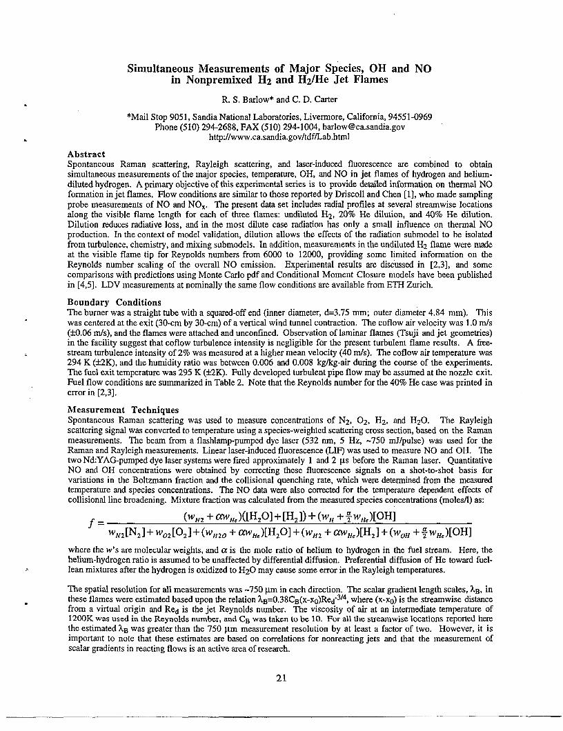
Boundary ConditionsThe burner was a straight tube with a squared-off end (inner diameter, d=3.75 mm; outer diameter 4.84 mm). Thiswas centered at the exit (30-cm by 30-cm) of a vertical wind tunnel contraction. The coflow air velocity was 1.0 mls(M).06 rids), and the flames were attached and unconfined. Observation of huninar flames (Tsuji and jet geometries)in the facility suggest that coflow turbulence intensity is negligible for the present turbulent flame results. A kstream turbulence intensity of 270 was measured at a higher mean velocity (40 m/s). The coflow air temperature was294 K @2K), and the humidity ratio was between 0.006 and 0.008 kg/kg-air during the course of the experiments.The fuel exit temperature was 295 K (fiK). Fully developed turbulent pipe flow maybe assumed at the nozzle exit.Fuel flow conditions are summarized in Table 2. Note that the Reynolds number for the 40’% He case was printed inerror in [2,3].
Measurement TechniquesSpontaneous Raman scattering was used to measure concentrations of N2, 02, H2, and H20. The Rayleighscattering signal was converted to temperature using a species-weighted scattering cross section, based on the Ramanmeasurements. The beam from a flashhunp-purnped dye laser (532 nm, 5 Hz, -750 mJ/pulse) was used for theRaman and Rayleigh measurements. Linear laser-induced fluorescence (LIF) was used to measure NO and OH. Thetwo Nd:YAG-pumped dye laser systems were fired approximately 1 and 2 ps before the Raman laser. QuantitativeNO and OH concentrations were obtained by correcting these fluorescence signals on a shot-to-shot basis forvariations in the Boltzmann fraction and the collisional quenching rate, which were determined from the measuredtemperature and species concentrations. The NO data were also corrected for the temperature dependent effects ofcollisional line broadening. Mixture fraction was calculated from the measured species concentrations (moles/l) as:
f. (w., + wJ([H,OI +[H,]) + (wH+;wJ[WwjvJN21+ W02[021 + (WH20 + WJ[H201 + (WH2 + WHe)[H21 + (woH + ; WHe)[oHl
where the w’s are molecular weights, and a is tie mole ratio of helium to hydrogen in the fuel stream. Here, thehelium-hydrogen ratio is assumed to be unaffected by differential diffusion. Preferential diffusion of He toward fuel-Iean mixtures after the hydrogen is oxidized to H20 may cause some error in the Rayleigh temperatures.
The spatial resohltion for all measurements was -75(I pm in each dkection. The scahr gradient length scales, %B, inthese flames were estimated based upon the relation kB=().38CB(X-Xo)Red ‘3’4, where (x-xo) is the streamwise distancefrom a virtual origin and Red is the jet Reynolds number. The viscosity of air at an intermediate temperature of1200K was used in the Reynolds number, and CB was taken to be 10. For all the streamwise locations reported herethe estimated %Bwas greater than the 750 pm measurement resolution by at least a factor of two. However, it isimportant to note that these estimates me based on correlations for nonreacting jets and that the measurement ofscalar gradients in reacting flows is an active area of research.
21
Calibrations and UncertaintiesThe temperature dependent calibration functions for each of the Raman channels were determined by measuringsignals from H2-air flat flames over a wide range of conditions above a Hencken burner. (The Hencken burner is anearly-adiabatic burner consisting of an array of small fuel tubes arranged in a stainless-steel honeycomb matrix thatallows for the flow of air.) OH measurements were referenced to a Hz-air Hencken burner flame at an equivalenceratio of $=0.94 (T-2350 K), where the OH number density was measured by laser absorption. The NO calibrationfactor was determined by doping lean premixed laminar flames with known concentrations of NO and differencing thesignals for two doping levels.
Measurement precision is limited by shot noise in the Raman and LIF signals, shot-to-shot variation in theRaman/Rayleigh laser Iineshape, and noise in the laser energy measurement used in determining Rayleightemperature. Table 1 includes the standard deviations of results in representative calibration flames. Table 1 alsoincludes estimates of potential systematic errors in the measured scalars. These estimates are based on repeatabilityof Raman calibrations, changes in the Rarnan/Rayleigh laser characteristics during experiments, drift in the LIF dyelaser wavelengths, and uncertainties in the fluorescence calibrations and corrections.
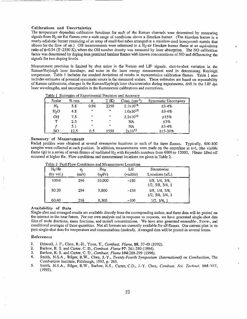
Table 1 Estimates of Experimental Precision and Accuracy
scalar 70 rms 4 T (K) Cone. (cm-3) Systematic Uncertainty
N2 3,8 0.94 2350 2.1X1018 *3-4%
H20 4.8 “ “ 1.OX1O18 &3-4y*
OH 7.5 “ “ 2.2xlol~ *15%
T 2.5 “ ,, NA *3 ‘%
f 5.1 “ ,, NA *3-4%
NO 12.5 0.5 1550 2X10¹³ A15.20910
Summarv of MeasurementsRadial pr~files were obtained at several streamwise locations in each of the three flames. Typically, 600-800samples were collected at each position. In addition, measurements were made on the centerline at x=L (the visibleflame tip) in a series of seven flames of undiluted H2 with Reynolds numbers from 6000 to 12000. Flame lifted-offoccurred at higher Re. Flow conditions and measurement locations are given in Table 2.
Table 2 Fuel Flow Conditions and Measurement LocationsH2:He Uj Red IJd Streamwise 1
(by VO1.) (m/s) (Ujd/V) (visible) Locations (x/L)
100:0 296 10,000 -180 1/8, 114, 318,1/2, 5/8, 3/4, 1
80:20 294 9,800 -150 1/8, 114, 3/8,1/2, 5/8, 3/4, 1
I 60:40 256 8,300 ‘“loo 1/2, 3/4, 1 I
Availability of DataSingle-shot and averaged results are available directly from the corresponding author, and these data will be posted onthe internet in the near future. For our own analysis and in response to requests, we have generated single-shot datafiles of mole fractions, mass fractions, and molefl concentrations. We have also generated ensemble-, Favre-, andconditional averages of these quantities. Not all formats are currently available for all flames. Our current plan is topost single-shot data for temperature and concentrations (moles/l). Averaged data will be posted in several forms.
References
1. Driscoll, J. F., Chen, R.-H., Yoon, Y., Combust. Flame, 88, 37-49 (1992).2. Barlow, R. S. and Carter, C. D., Combust. Flame 97:261-280 (1994).3. Barlow, R. S. and Carter, C. D., Combust. Flame 104:288-299 (1996).4. Smith, N. S. A., Bilger, R.W., Chen, J.-Y., Twenty-Fourth Symposium
Combustion Institute, Pittsburgh, 1992, p. 263.5. Smith, N. S. A., Bilger, R. W., Barlow, R. S., Carter, C. D., J.=Y. Chen,
(1995).
(International) on Combustion, The
Combust. Sci. TechnoL 105:357,
22
Laser Doppler VelocimetryMeasurements in Turbulent Non PremixedHydrogen/Helium Flames
M. Flury *, M. Schlatter
Institute of Energy TechnologyEnergy Systems LaboratoryETH Zuerich Switzerland
e-Mail: Jury@ iet.mavt.ethz.ch or schlatter@ iet.mavt.ethz.chWWW.:http://wnw.les. iet.ethz.ch/comb/nodnox.html
1 Abstract
Laser Doppler Velocimetry (LDV) measurements (including the Reynolds Stress tensor) were conducted in a turbulent nonpremixed hydrogen flame. The hydrogen was diluted with O%, 20% and 40% helium. The burner was a straight tube (inner
diameter 3.75 mm) centered in a coflowing air stream. The flamesweresimilarto the onesinvestigatedby R.S. BarlowandC.D.CarterwithRaman/Rayleigh/LIFat SandiaNationalLaboratories(BarlowandCarter,1994).Additionallysimpleheatfluxmeasurementswereperformedandfor illustrationpurposes integral video pictures were taken.
2 Boundary Conditions
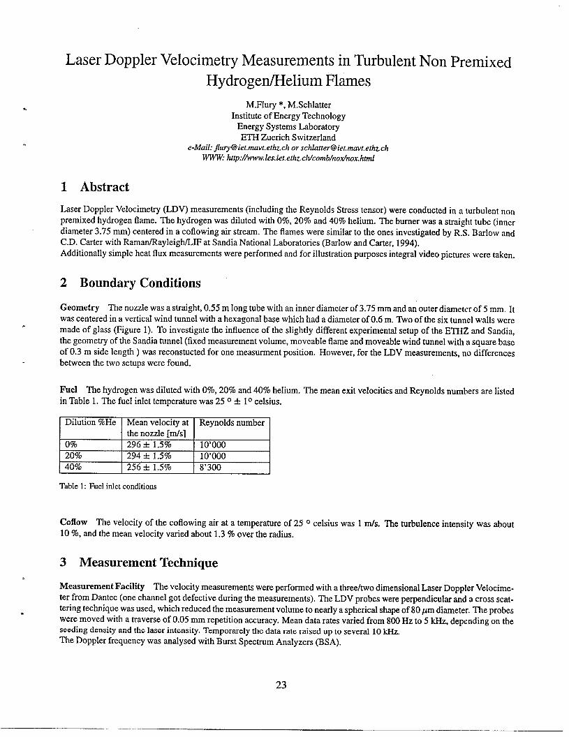
Geometry The nozzle was a straight, 0.55 m long tube with an inner diameter of 3.75 mm and an outer diameter of 5 mm. Itwas centered in a vertical wind tunnel with a hexagonal base which had a diameter of 0.6 m. Two of the six tunnel walls weremade of glass (Figure 1). To investigate the influence of the slightly different experimental setup of the ETHZ and Sandia,the geometry of the Sandia tunnel (fixed measurement volume, moveable flame and moveable wind tunnel with a square baseof 0.3 m side length ) was reconstructed for one measurement position. However, for the LDV measurements, no differencesbetween the two setups were found.
Fuel The hydrogenwasdilutedwithO%,20%and40%helium.The meanexit velocitiesandReynoldsnumbersare listedin Table1. Thefuel inlet temperaturewas250 + 10celsius.
Dilution %He Mean velocity at Reynolds numberthe nozzle [m/s]
o% 296 + 1.5% 10’00020% 294 + 1.5% 10’000
40% 256 + 1.5% 8’300
Table 1: Fuel intet conditions
Coflow The velocity of the coflowing air at a temperature of 250 celsius was 1 m/s. The turbulence intensity was about10 Yo,and the mean velocity varied about 1.3 Yoover the radius.
3 Measurement Technique
Measurement Facility The velocity measurements were performed with a three/two dimensional Laser Doppler Velocime-ter from Dantec (one channel got defective during the measurements). The LDV probes were perpendicular and a cross scat-tering technique was used, which reduced the measurement volume to nearly a spherical shape of 80 #m diameter. The probeswere moved with a traverse of 0.05 mm repetition accuracy. Mean data rates varied from 800 Hz to 5 kHz, depending on theseeding density and the laser intensity. Temporarily the data rate raised up to several 10 kHz.The Doppler frequency was analysed with Burst Spectrum Analyzers (BSA).
23
Data Analysis With a Shannon algorithm (Veynante and Candel, 1993) the non equal spaced raw data was remapped to a
regularly spaced timebase. This procedure reduces LDV biases which occur due to higher measurement probabilities of fasterseeding particles and due to conditional sampling. The reliability of the Shannon algorithm was shown by (Veynante andCandel, 1988) and (Flury and Schlatter, 1996). Based on the remapped data, Reynolds averaged mean, rms, and ReynoldsStress tensor components were calculated. Furthermore for the 20% dilution integral time scales were determined.
-.
Radiation Measurements To estimate the radiative heat flux of the flame, a black plate (Figure 2) was moved along the flame
at a radial distance of 0.3 m. The temperature of the plate was measured with a calibrated thermocouple. With an additionalcorrection for the convective heat losses the emitted radiation could be determined.
\\, Isolatio
\Contraction \
~hermocouple Type
Figure 1: Sketch of the test facility Figure 2: Sketch of the black plate sensor
4 Summary of Measurements
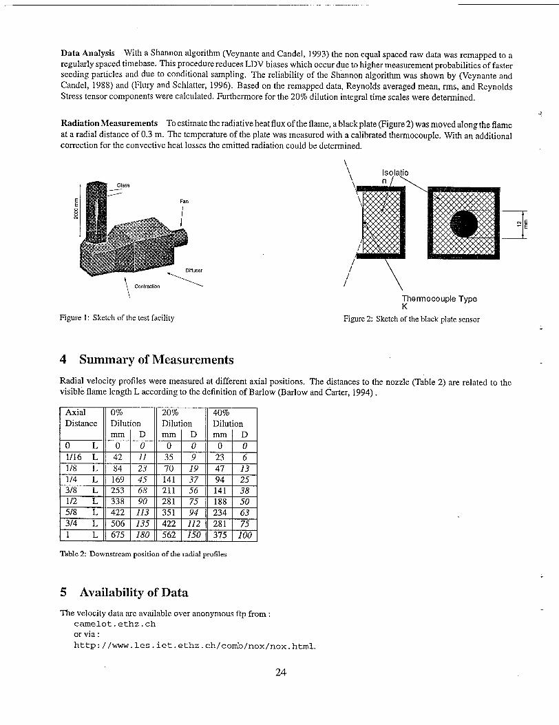
Radial velocity profiles were measured at different axial positions. The distances to the nozzle (Table 2) are related to thevisible flame length L according to the definition of Barlow (Barlow and Carter, 1994) .
Axial o% 20% 40%Distance Dilution Dilution Dilution
mm D mm D mm D
OL o 0 0 0 0 0
1/16 L 42 11 35 9 23 6
1/8 L 84 23 70 19 47 13
1/4 L 169 45 141 37 94 253/8 L 253 68 211 56 141 381/2 L 338 90 281 75 188 505/8 L 422 113 351 94 234 633/4 L 506 135 422 112 281 75
1 L 675 180 562 150 375 100
Table 2: Downstream position of the radial profiles
5 Availability of Data
The velocity data are available over anonymous ftp from:
carnelot . ethz . ch
or via:htzt-p: //WWW. les . iet. ethz . ch/comb/nox/nox .html.
24
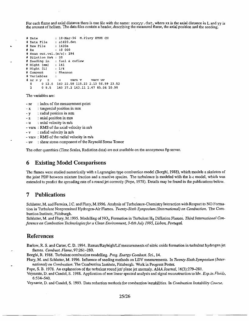
For each flame and axial distance there is ?ne file with the na~e: SXXYY. dat, where xx is the ax~a! distance in L and yy isthe amount of hehum. The data files contain a header, descrlbmg the measured flame, the axial pos:hon and the seeding.
# Date : 18-Mar-96 M.FlurY ETHZ CH# Data File : s1420.dat
* # Raw File : 1420a# Re : 10 000# Mean out.vel.[m/s]: 294# Dilution He% : 20# Seeding in : fuel & coflow# Hight [mm] : 141# Hight [L] : 1/4# Comment : Shannon# Variables :#nrxy z u varu v varv uv
o 0 12.5 140 22.58 115.23 2.13 56.99 23.522 0 8.5 140 37.2 163.11 2.67 85.04 20.98
The variables are:
- nr : index ofthe measurementpoint-x : tangential position inmm
-Y : radial position inmm-z : axial position inmm-u : axial velocity inrnls-varu : RMSofthe axial veIocityin m/s-v : radial velocity in mfs-varv : RMSofthe radial velocity inm/s
- Uv : shear stress componentofthe Reynold Stress Tensor
Theotherquantities (TimeScaIes, Radiation data) arenotavailable ontheanonymous ftpserver.
6 Existing Model Comparisons
The flames were studied numerically with a Lagrangian type combustion model (Borghi, 1988), which models a skeleton of
tiejoint PDF between mixture fraction andareactive species. l%eturbulence ismodeled with thek-c model, which wasextended to predict the spreading rate of a round jet correctly (Pope, 1978). Details may be found in the publications below.
7 Publications
Schlatter, M. and Ferreira, J.C. and Flury, M. 1996. Analysis of Turbulence-Chemistry Interaction with Respect to NO Forma-tion in Turbulent Nonpremixed Hydrogen-Air Flames. Twenty-Sixth Symposium (International) on Combustion. The Com-bustion Institute, Pittsburgh.Schlatter, M. and Flury, M. 1995. Modelling of NOX Formation in Turbulent H2 Diffusion Flames. Third International Con-ference on Combustion Technologies for a Clean Environment, 3-6th July 1995, Lisbon, Portugal.
References
Barlow, R. S. and Carter, C. D. 1994. Raman/Rayleigh/Lif measurements of nitric oxide formation in turbulent hydrogen jet. flames. Combust. Flame, 97:261-280.
Borghi, R. 1988. Turbulent combustion modelling. Prog. Energy Combust. Sci., 14.Flury, M. and Schlatter, M. 1996. Influence of seeding methods on LDV measurements. In Twenty-Sixth Symposium (Inter-
. national) on Combustion. The Combustion Institute, Phtsburgh. Work in Progress Poster.Pope, S, B. 1978, An explanation of the turbulent round jet/ plane jet anomaly. AL4A Journal, 16(3):279-281.Veynante, D. and Candel, S. 1988. Application of non linear spectral analysis and signal reconstruction to Idv. Exp.in.Fluids,
6:534-540.Veynante, D. and Candel, S. 1993. Data reduction methods for combustion instabilities. In Combustion znstabili~ Course.
25126

Blank Page
Intemationul Workshop on Memurement and Computation of Turbulent Nonpt-em-xedFtis, NaplesItaly,July 26-27,1996
-,
.
LDV AND CARS MEASUREMENTS IN SWIRLING AND NON-SWIRLINGCOAXIAL TURBULENT HYDROGEN JET DIFFUSION FLAMES
Fumiaki Takahashi*, Marlin D. Vangsness, Mark D. Durbin, and W. John Schmoll
University of Dayton Research Institute300 College Park
Dayton, OH 45469-0140Telephone: (513) 252-8138
FAX: (513) 252-9917e-mail ftakahas @engr.udayton.edu
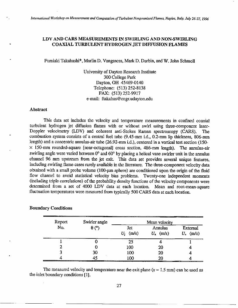
Abstract
This data set includes the velocity and temperature measurements in confined coaxialturbulent hydrogen jet diffusion flames with or without swirl using three-component laser-Doppler velocimetry (LDV) and coherent anti-Stokes Rarnan spectroscopy (CARS). Thecombustion system consists of a central fiel tube (9.45-mm id., 0.2-rnm lip thickness, 806-mmlength) and a concentric annulus-air tube (26.92-mm id.), centered in a vertical test section (150-x 150-mm rounded-square [near-octagonal] cross section, 486-mm length). The annulus-air
swirling angle were varied between 0° and 60° by placing a helical vane swirler unit in the annuluschannel 96 mm upstream from the jet exit. This data set provides several unique features,including swirling flame cases rarely available in the literature. The three-component velocity data
obtained with a small probe volume (100-~m sphere) are conditioned upon the origin of the fluidflow channel to avoid statistical velocity bias problems. Twenty-one independent moments(including triple correlations) of the probability density functions of the velocity components weredetermined from a set of 4000 LDV data at each location. Mean and root-mean-squarefluctuation temperatures were measured from typically 500 CARS data at each location.
Boundary Conditions
Report Swirler angle Mean velocityNo. e (0) Jet Anrluhls External
Uj (m/S) u, (In/s) u, (In/s)
1 0 25 4 12 0 100 20 43 30 100 20 44 45 100 20 4b
The measured velocity and temperature near the exit plane (x= 1.5 mm) can be used asthe inlet boundary conditions [1].
27
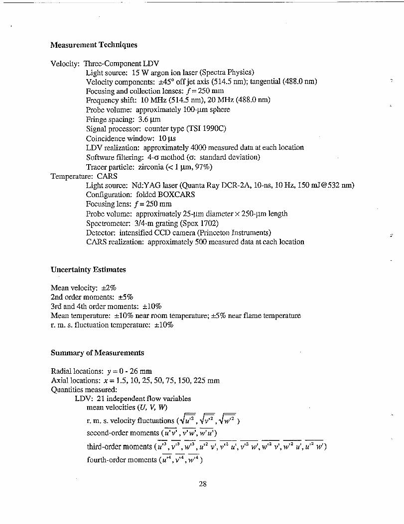
Measurement Techniques
Velocity: l%ree-Component LDVLight source: 15 W argon ion laser (Spectra Physics)Velocity components: A45” off jet axis (514.5 run); tangential (488.0 nrn)Focusing and collection lenses: j= 250 mmFrequency shfi 10 MHz (514.5 rim), 20 MHz (488.0 nrn)Probe volume: approximately 100-ym sphereFringe spacing: 3.6 ~mSignal processo~ counter type (TSI 1990C)Coincidence window: 10 p.sLDV realization: approximately 4000 measured data at each location
Software faltering: 4-0 method (C standard deviation)Tracer particle: zirconia (< 1 pm, 97%)
Temperature: CARSLight source: Nd:YAG laser (Quanta Ray DCR-2A, 10-ns, 10 Hz, 150 mJ@532 nm)Cordlguration: folded BOXCARSFocusing lens: ~= 250 mm
Probe volume: approximately 25-&m diameter x 250-pm lengthSpectrometer: 3/4-m grating (Spex 1702)Detectoc intensified CCD camera (Princeton Instruments)CARS realization: approximately 500 measured data at each location
Uncertainty Estimates
Mean veloci~. &2%2nd order moments: &5%3rd and 4th order moments: A1O%Mean temperature: MO% near room temperature; &5% near flame temperaturer. m.s. fluctuation temperature: &10%
Summary of Measurements
Radial locations: y = 0-26 mmAxial locations: x = 1.5, 10,25,50,75, 150,225 mmQuantities measured:
LDV: 21 independent flow variablesmean velocities (U, W W)
JRF,lmr. m.s. velocity fluctuations ( u——
second-order moments (~, v’w’, w’u’ )—— .— __ —— —
third-ordermoments(U’3,V’3,W’3, N v’, V’2u’>V’2w’, W*2v’, W’2u’, U’2w’]—. —
fourth-order moments (U’4, V’4, W’4)
28
1
*
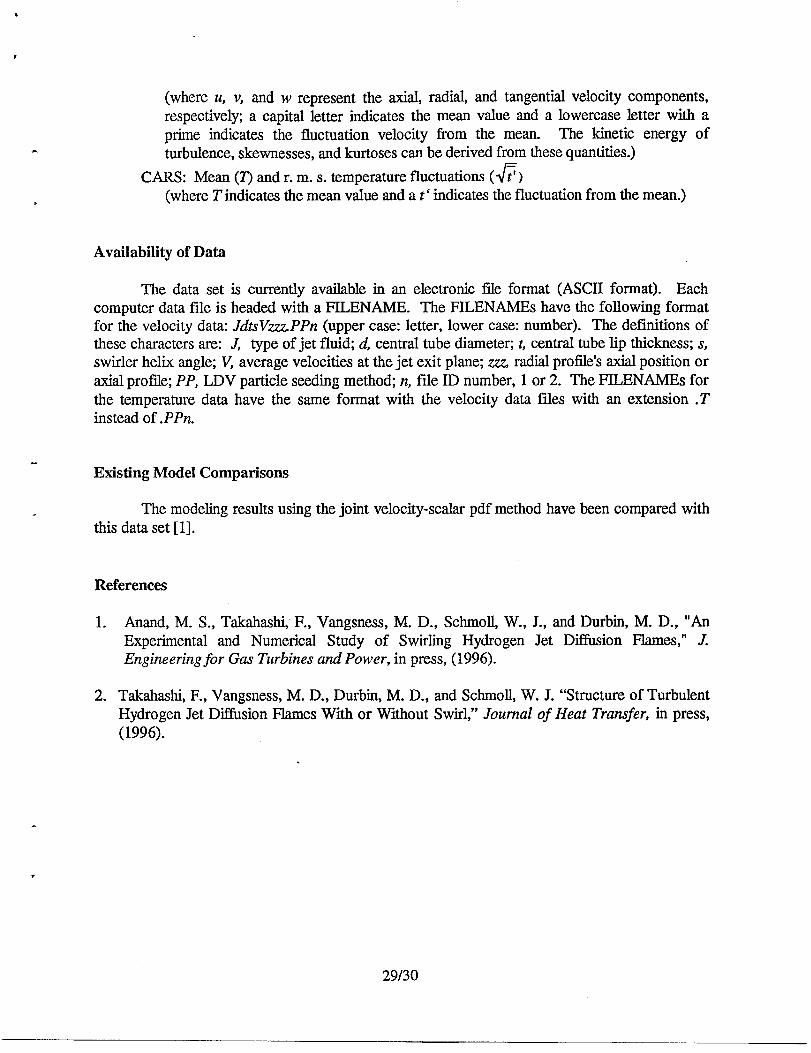
(where u, v, and w represent the axial, radial, and tangential velocity components,respectively a capital letter indicates the mean value and a lowercase letter with aprime indicates the fluctuation velocity from the mean. The kinetic energy ofturbulence, skewnesses, and kurtoses can be derived from these quantities.)
CARS: Mean (T) and r. m.s. temperature fluctuations (~)(where Tindicates the mean value and a t‘indicates the fluctuation from the mean.)
Availability of Data
The data set is currently available in an electronic fde format (ASCII format). Eachcomputer data file is headed with a FILENAME. The FILENAMEs have the following formatfor the velocity data: JdtsVZzPPn (upper case: letter, lower case: number). The definitions ofthese characters are: J type of jet fluid; d, central tube diameter; t,central tube lip thickness; s,swirler helix angle; V, average velocities at the jet exit plane; .ZZZ,radial protlle’s axial position oraxial profile; PP, LDV particle seeding method; n, fde ID number, 1 or 2. The FILENAMEs forthe temperature data have the same format with the velocity data fdes with an extension .Tinstead of .PPn.
.
Existing Model Comparisons
The modeling results using the joint velocity-scalar pdf method have been compared withthis data set [1].
References
1. Anand, M. S., Takahashi, F., Vangsness, M. D., Schmoll, W., J., and Durbin, M. D., “AnExperimental and Numerical Study of Swirling Hydrogen Jet DiHusion Flames,” J.Engineering for Gas Turbines and Power, in press, (1996).
2. Takahashi, F., Vangsness, M. D., Durbin, M. D.,Hydrogen Jet Diffusion Flames With or Without(1996).
and Schmoll, W. J. “Structure of TurbulentSwirl:’ Journal of Heat Transfer, in press,
“
29/30

Blank Page
International Workshop on Measuremeru and Computation of Turbulent Nonprem’xedFlames, Naples, Italy, July 26-2Z 1996
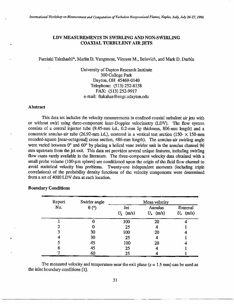
LDV MEASUREMENTS IN SWIRLING AND NON-SWIRLINGCOAXIAL TURBULENT AIR JETS
Fumiaki Takahashi*, Marlin D. Vangsness, VincentM., Belovich, and Mark D. Durbin
University of Dayton Research Institute300 College Park
Dayton, OH 45469-0140Telephone: (513) 252-8138
FAX: (513) 252-9917e-maik ftakahas @engr.udayton.edu
Abstract
This data set includes the velocity measurements in confined coaxial turbulent air jets withor without swirl using three-component laser-Doppler velocimetry (LDV). The flow systemconsists of a central injector tube (9.45-mm id., 0.2-mm lip thickness, 806-mm length) and a
concentric annulus-air tube (26.92-mm id.), centered in a vertical test section (150- x 150-mmrounded-square [near-octagonal] cross section, 486-mm length). The ammlus-air swirling angle
were varied between 0° and 60° by placing a helical vane swirler unit in the annulus channel 96mm upstream from the jet exit. This data set provides several unique features, including swirlingflow cases rarely available in the literature. The three-component velocity data obtained with a
small probe volume (100-~m sphere) are conditioned upon the origin of the fluid flow channel toavoid statistical velocity bias problems. Twenty-one independent moments (including triplecorrelations) of the probability density functions of the velocity components were determinedfrom a set of 4000 LDV data at each location.
Boundary Conditions
Report Swirler angle Mean velocityNo. e (0) Jet Annulus External
Vj (In/s) u, (In/s) IVe (m/s)
1 0 100 20 42 0 25 4 13 30 100 20 44 30 25 4 15 45 100 20 46 45 25 4 1
The measured velocity and temperature near the exit plane (x= 1.5 mm) can be used asthe inlet boundary conditions [1].
31
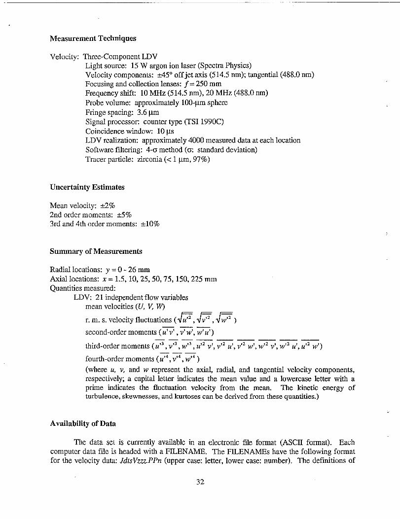
Measurement Techniques
Velocity: Three-Component LDVLight source: 15 W argon ion laser (Spectra Physics)Velocity components: &45° off jet axis (514.5 rim); tangential (488.0 m-n)Focusing and collection lenses: j= 250 mmFrequency shif~ 10 MHz (514.5 rim), 20 MHz (488.0 nm)Probe volume: approximately 100-pm sphere
Fringe spacing: 3.6 pmSignal processor: counter type (TSI 1990C)Coincidence window: 10 KSLDV realization: approximately 4000 measured data at each locationSoftware filtering: 4-0 method (m standard deviation)Tracer particle: zirconia (< 1 Lm, 97%)
Uncertainty Estimates
Mean velocity: &2%2nd order moments: &5%3rd and 4th order moments: &lO%
Summary of Measurements
Radial locations: y = 0-26 mmAxial locations: x = 1.5, 10,25,50,75, 150,225 mmQuantities measured:
LDV: 21 independent flow variablesmean velocities (U, w W)
F,lmlmr. m.s. velocity fluctuations ( u——
second-order moments (~, v’w’, w’u’).— .— —— —— _
third-order moments ( U’3,V’3,W’3, U’*v’, V’* u’, V’z w’, W’z v’, W’z u’, U’z w’)—— —
fourth-order moments (U’4, V’4, W’4)
(where u, v, and w represent the axial, radial, and tangential velocity components,respectively, a capital letter indicates the mean value and a lowercase letter with aprime indicates the fluctuation velocity from the mean. The kinetic energy ofturbulence, skewnesses, and kurtoses can be derived from these quantities.)
.
Availability of Data
The data sel is currently available in an electronic file format (ASCII format). Eachcomputer data file is headed with a FILENAME. The FILENAMEs have the following formatfor the velocity data: JdtsVzz.r,.PPn (upper case: letter, lower case: number). The definitions of
32
these characters are: J, type of jet fluid; d, central tube diamete~ t, central tube lip thickness; S,swirler helix angle; V, average velocities at the jet exit plane; zzz, radial profile’s axial position oraxial profd~ PP, LDV particle seeding method; n, file ID number, 1 or 2.
.
Existing Model Comparisons
The modeling results using the joint velocity-scalar pdf method have been compared withthis data set [1].
References
1.
2.
Anand, M. S., Pope, S. B., and Mongia, H. C., “PDF Calculations for Swirling Flows,” AI’J., in press, (1996).
Takahashi, F., Vangsness, M. D., and Belovich, V. M., “Conditional LDV Measurements inSwirling and Non-Swirling Coaxial Turbulent Air Jets for Model Validation:’ AI&4 PaperNo. 92-0580, January 1992.
33/34
-

Blank Page
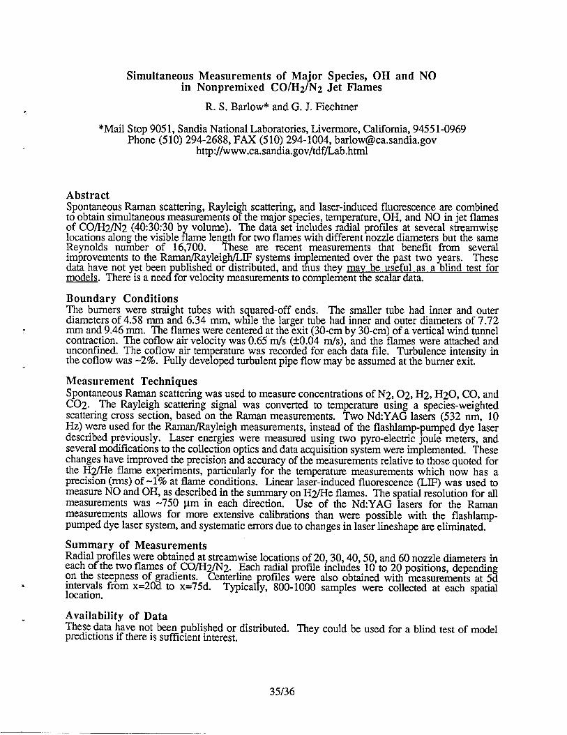
Simultaneous Measurements of Ma”or Species, OH and NO/“in Nonpremixed CO/H2 N2 Jet Flames
R. S. Barlow* and G. J. Fiechtner
*Mail Stop 9051, Sandia National Laboratories, Livermore, California, 94551-0969Phone (510) 294-2688, FAX (510) 294-1004, [email protected]. gov
http://www.ca.sandia. gov/tdf/Lab.html
AbstractSpontaneous Raman scattering, Rayleigh scattering, and laser-induced fluorescence axe combinedto obtain simultaneous measurements of the major species, temperature, OH, and NO in jet flamesof CO/H21N2 (40:30:30 b volume). The data set includes radial profiles at several streanmvise
ilocations along the visible ame len th for two flames with different nozzle diameters but the sameReynolds number of 16,700. h ese are reeent measurements that benefit from severalimprovements to the Rarnan/Rayleigh/LIF systems im lemented over the past two years. These
idata have not yet been ublished or distributed, and us they may be useful as a blind test forc?models. There is a nee for velocity measurements to complement the scalar data.
Boundary ConditionsThe burners were straight tubes with squared-off ends. The smaller tube had inner and outerdiameters of 4.58 mm and 6.34 mm, whale the larger tube had inner and outer diameters of 7.72mm and 9.46 mm. The flames were centered at the exit (30-cm by 30-cm) of a vertical wind tunnelcontraction. The coflow air velocity was 0.65 m/s (YO.04 m/s), and the flames were attached andunconfined. The coflow air tern erature was recorded for each data file. Turbulence intensity in
fthe coflow was -2%. Fully deve oped turbulent pipe flow maybe assumed at the burner exit.
Measurement TechniquesSpontaneous Raman scattering was used to measure concentrations of N2, 02, H2, H20, CO, andC02. The Rayleigh scattering signal was converted to temperature using a species-weightedscattering cross section, based on the Raman measurements. Two NdYAG lasers (532 nm, 10Hz) were used for the Raman/Rayleigh measurements, instead of the flashlamp-pumped dye laserdescribed previously. Laser energies were measured using two pyre-electric joule meters, andseveral modifications to the collection optics and data acquisition system were implemented. Thesechanges have improved the precision and accuracy of the measurements relative to those quoted forthe H~e flame experiments, particularly for the temperature measurements which now has aprecision (rms) of -1% at flame conditions. Linear laser-induced fluorescence (LIF) was used tomeasure NO and OH, as described in the summary on H2/He flames. The spatial resolution for allmeasurements was -750 ~m in each direction. Use of the Nd:YAG lasers for the Ramanmeasurements allows for more extensive calibrations than were possible with the flashlamp-pumped dye laser system, and systematic errors due to changes in laser lineshape are eliminated.
Summary of MeasurementsRadial refiles were obtained at streamwise locations of 20~ 30,40,50, and 60 nozzle diameters in
?each o the two flames of CO/H2/N2. Each radial profde includes 10 to 20 positions, dependingon the steepness of gradients. Centerline refiles were also obtained with measurements at 5d
Jintervals from x=20d to x=75d. Typica y, 800-1000 samples were collected at each spatiallocation.
Availability of DataThese data have not been published or distributed. They could be used for a blind test of modelpredictions if there is sufficient interest.
35/36

Blank Page
VELOCITY, OH-CONCENTRATION AND TEMPERATURE MEASUREMENTSIN A PILOTED NATURAL GAS DIFFUSION FLAME.
Th.H. van ‘der Meer*, I. Mantzaras, P.P.J. Stroomer and J.E. de Vries.
Delft University of Technology
Department of Applied Physics
P.O. Box 5046, 2600 GA Delft
The Netherlands
tel.: 31-15-2782477, FAX: 31-15-2781204
e-mail: [email protected]. tudelft.nlhttp: //duttwte.tn.tudelft. nl:8080/trwthome. html
ABSTRACT
LDA, CARS, LIF and PLIF measurements have been performed in natural gas
flames. The burner consists of a round fuel tube (diameter 6 mm) and an annu-
lus (inner diameter 15 mm., outer diameter’45 mm) for primary air supply. The
composition of the Dutch natural gas is (in mole fractions) 81.3 70 methane, 2.8
% ethane, 14.3 % nitrogen, 0.9 % carbon dioxide and 0.7 % other hydrocarbons.The pilot flames are positioned at the rim between central pipe and annulus. The
flame environment is confined in a octagonal glass chamber (57 mm. wide) with
a low velocity uniform air flow to prevent large scale reciculat ions. Variations of
the natural gas velocity, the primary air velocity and the primary air temperature
(295 K and 675 K) resulted in six flames. Visualizations of the OH-concentrationfields in these flames clearly show the different turbulent structures with extinc-tion phenomena most prominent in the flames with the highest gas and primary
air velocities disappearing in the preheated flames. One of the flames has been
examined most thoroughly and will be presented in the data set.
BOUNDARY CONDITIONS
Mean velocities:
Ufu.l = 21.9 m/suann = 4.4 m/s
UcOfI= 0.3 m/s
All inlet streams at room temperature, 295 K
● uniform profiles for fuel inlet
● profiles from developed annulus flow for annulus, calculated using standard
k-epsilon model with wall functions
● uniform profiles for outer coflow
This leads to a set of profiles that are available in the data set.
37
MEASUREMENT TECHNIQUES
LDA:
A 2D back scatter LDA system was used. Size of the measuring volume: 0.15 x2.1 mm.Statistical uncertainties 1 to 1.5 % in averaged velocities, 2.5 % in rms values. Thedifferences between ensemble averaging and residence time weighted averaging
was only present (up to 3 70) in the peak maxima of the rms distributions.
CARS:
A folded BOXCARS arrangement was used resulting in an interaction length of
the Stokes and pump beams of 0.9 mm. Temporal resolution: 6 ns. The uncer-
tainty of the mean temperatures varies with the position in the flame. In regions
with steep gradients the CARS temperatures are too low by as much as 160
K. In regions without steep gradients the uncertainty is about 50 K. Averaged
temperatures compared well with thermocouple measurements. Calibrations in
a flat flame from a McKenna burner resulted in temperatures within 25 K with
numerical simulations.
LIF:
lD measurements with measuring volume depth of approximately 0.75 mm. Tem-
poral resolution of 6 ns. Calibration has been done in a rich and a lean Iaminar
flame from the McKenna burner. Estimated uncertainty of the averaged OH con-
centration is 5070
SUMMARY OF MEASUREMENTS
We have radial profiles at axial positions 50, 100, 150, 200 and 250 mm.
● mean axial velocitye mean radial velocityo rms-values of the axial velocity● rms-value of the radial velocity● the turbulent kinetic energy● The Reynolds stress ~e Mean OH concentrations● rms OH-concentrations@ Mean temperatureso rms values of temperature
The LDA measurements have also been performed very close to the burner exitat axial position of 3 mm. Also pdf’s of velocities, OH-concentrations and tem-perature are available.
The data will be made available on an anonymous ftp-site before the end of June.
38
In our own Heat Transfer Section we have modelled this flame with assumed
shape pdf models as well as Monte Carlo pdf models combined with different
chemical models.
REFERENCE:
Peeters, T. W. J., Stroomer, P. P. J., de Vries, J. E., Roekaerts, D. and Hoogen-
doorn, C. J., Comparative experimental and numerical investigation of a piloted
turbulent natural gas diffusion flame, 25th Int. Symposium on Combustion, the
Combustion Institute, 1994, pp. 1241-1248.
39/40

Blank Page
,
Turbulent Nonpremixed Flames Stabilised on aPiloted Jet Burner
A.R. Masril
Department of Mechanical and Mechatronic Engineering
The University of Sydney, NSW 2006, Australia
R.W. Dibble
Department of Mechanical Engineering
University of California, Berkeley California, USA
and
R.S. Barlow
Combustion Research Facility
Sandia National Laboratories, Livermore, CA. USA.
Abstract
The piloted jet burner was developed at the University of Sydney, Australia, and is proven to be
a useful tool to investigate streaming (parabolic) turbulent nonpremixed flames for variety of fuels
and wide range of Reynolds Numbers. The geometry of the burner is relatively simple and consists
of an axisymmetric jet with a thin wall nozzle and an annulus where the pilot gases burn. The
hot gases from the pilot stabilise the main flame to the nozzle which forces extinction to occur at
higher jet velocities. The pilot flame gases have the same C/H and O/H ratios as that of the main
fuel so that the combustion products of both the pilot and the main fuel are indistinguishable. The
flames are axisymmetric and the boundary conditions are relatively simple and well defined.
Flowfield data as well as temperature and composition data are available. The flowfield data are col-
lected at the University of Sydney using a conventional LDV technique and consist of radial profiles
of mean and rms fluctuations of the axial and radial velocity components for a range of axial loca-
tions. The flowfield data are available for selected flames only. Temperature and composition data
are instantaneous points measurements collected at the Combustion Research Facility, Sandia Na-
tional Laboratories, Livermore CA. Measurements have been made using the Raman/Rayleigh/LIF
technique to give instantaneous and simultaneous temperature and concentration of various species
at a single point in the flame. The species measured are: N2, 02, CH4 (or CH30H), CO, C02,
H2, H20, OH. A range of fuel mixtures and flame velocities from low to close to extinction are
1Author to whom correspondence should be addressed.
Email : [email protected]. su.oz.auPhone : + 6123512288, Facsimile: + 6123517060http: //www.me.su.oz. au.research.energy. energy.html
41
available. The objective of this work is to provide a comprehensive bank of data which may be
used by modelers of turbulent nonpremixed combustion.
Boundary Conditions
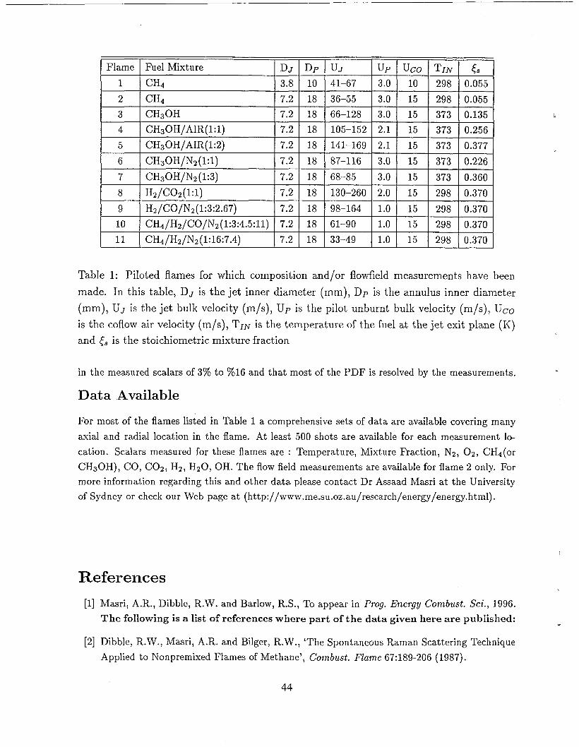
Table I contains a list of fuels and flow conditions measured for this burner. In all of these flames
the burner have a fuel jet nozzle which extends to more than 40 jet diameters upstream of the
burner exit plane to ensure fully developed pipe flow of the jet. The burnt pilot gas velocity is
calculated from the unburnt pilot gas velocity assuming ideal gas behaviour and using the adiabatic
pilot flame temperature. The pilot gases are at stoichiometric conditions. The wind tunnel has
a 2% turbulence intensity in the free stream. All flames are visibly symmetric and clean of soot.
Measured boundary conditions and more detailed information for the piloted jet burner may be
found in [1]..
Measurements Uncertainty
There are many factors which may contribute to the overall error associated with the measurements
presented here. These include shot noise, electronic noise, error associated with the optical set-up
and spatial resolution error. Other sources of errors which are specific to the Raman set-up include
the cross talk between the Raman signals, the fluorescence interference from soot precursors and
other molecules and the interpolation for the Raman calibration factors.
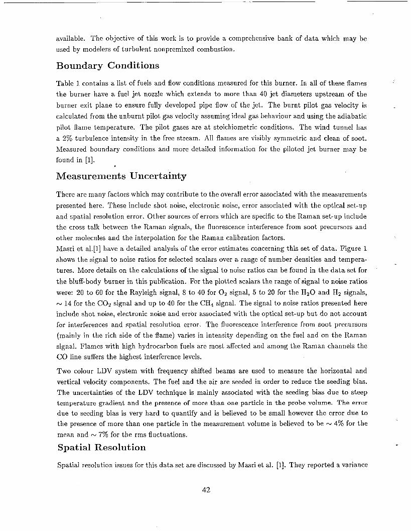
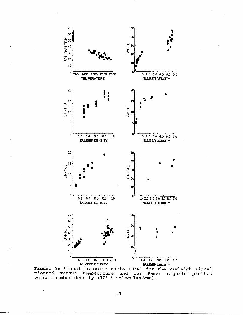
Masri et al. [1] have a detailed analysis of the error estimates concerning this set of data. Figure 1
shows the signal to noise ratios for selected scalars over a range of number densities and tempera-
tures. More details on the calculations of the signal to noise ratios can be found in the data set for
the bluff-body burner in this publication. For the plotted scalars the range of signal to noise ratios
were: 20 to 60 for the Rayleigh signal, 8 to 40 for 02 signal, 5 to 20 for the H20 and H2 signals,
= 14 for the C02 signal and up to 40 for the CH4 signal. The signal to noise ratios presented here
include shot noise, electronic noise and error associated with the optical set-up but do not account
for interferences and spatial resolution error. The fluorescence interference from soot precursors
(mainly in the rich side of the flame) varies in intensity depending on the fuel and on the Raman
signal. Flames with high hydrocarbon fuels are most affected and among the Raman channels the
CO line suffers the highest interference levels.
Two colour LDV system with frequency shifted beams are used to measure the horizontal and
vertical velocity components. The fuel and the air are seeded in order to reduce the seeding bias.
The uncertainties of the LDV technique is mainly associated with the seeding bias due to steep
temperature gradient and the presence of more than one particle in the probe volume. The error
due to seeding bias is very hard to quantify and is believed to be small however the error due to
the presence of more than one particle in the measurement volume is believed to be w 4% for the
mean and N 7% for the rms fluctuations.
Spatial Resolution
Spatial resolution issues for this data set are discussed by Masri et al. [1]. They reported a variance
42
“%r’f#.~oe
JAA_LA—500 1000 1500 2000 2500
TEMPERATURE
20-
15 -0f
? 10 -Cn
5 -
::
I:
.8!●
0.2 0.4 0.6 0.8 1.0
NUMBER DENSITY
20 -●
15 -o“o
I::2 10 -g3 **
o~0.2 0.4 0.6 0.8 1.0
NUMBER DENSITY
70
60[
●
50
?“ 40L.;&GC/Y30 ● ●
20f
●*
10
05.0 10.0 15.0 20.0 25.0
NUMBER DENSITY
50
40
0“30
?
1
w 20 #e
10
$
:;●
f)~1.0 2.0 3.0 4.0 5.0 6.0
NUMBER DENSITY
20
1
● 815e*
TN ●
; 10(n
●
5
●
OLkAAk—A1.0 2.0 3.0 4.0 5.0 6.0
NUMBER DENSITY
50-
40 -●
●
1“ ●
030 -
z320 :
●
10
tfj~
1.02.03 .04.05.06.07.0
NUMBER DENSITY
40.
30 -8
●o ●o ● ●
g 20 - ●UY
10 -
B
o .“’”’”’’ ”’’’’ ”’’’’’””~1.0 2.0 3.0 4.0 5.0
NUMBER DENSITY
Figure 1: Si9nal to noise ratio (S/N) for the Rayleigh signalplotted versus temperature and for Raman signals plottedversus number density (106 * molecules/cm3) .
43
Flame Fuel Mixture DJ Dp uJ up Uco TIN &
1 CHA 3.8 10 41-67 3.0 10 298 0.055
2 CHA 7.2 18 36-55 3.0 15 298 0.055
3 CH30H 7.2 18 66-128 3.0 15 373 0.135
4 CHsOH/AIR(l:l) 7.2 18 105-152 2.1 15 373 0.256
5 cH30H/AIR(l:2) 7.2 18 141-169 2.1 15 373 0.377
6 CH30H/Nz(l:l) 7.2 18 87-116 3.0 15 373 0.226
7 cH30H/N2(l:3) 7.2 18 68-85 3.0 15 373 0.360
8 Hz/COz(l:l) 7.2 18 130-260 2.0 15 298 0.370
9 Hz/CO/Nz(l:3:2.67) 7.2 18 98-164 1.0 15 298 0.370
10 CH~/HZ/CO/NZ(l:3 :4.5:11) 7.2 18 61-90 1.0 15 298 0.370
11 cH4/H2/N2(l:16:7 .4) 7.2 18 33-49 1.0 15 298 0.370
Table 1: Piloted flames for which composition and/or flowfield measurements have been
made. In this table, DJ is the jet inner diameter (mm), Dp is the annulus inner diameter
(mm), UJ is the jet bulk velocity (m/s), Up is the pilot unburnt bulk velocity (m/s), UCO
is the coflow air velocity (m/s), TIN is the temperature of the fuel at the jet exit plane (K)
and ~~ is the stoichiometric mixture fraction
in the measured scalars of 3% to Y016 and that most of the PDF is resolved by the measurements.
Data Available
For most of the flames listed in Table 1 a comprehensive sets of data are available covering many
axial and radial location in the flame. At least 500 shots are available for each measurement lo-
cation. Scalars measured for these flames are : Temperature, Mixture Fraction, N2, 02, CH4(or
CH30H), CO, C02, H2, H20, OH. The flow field measurements are available for flame 2 only. For
more information regarding this and other data please contact Dr Assaad Masri at the University
of Sydney or check our Web page at (http: //www.me.su.oz. au/research/energy /energy. html).
References
[1]Mas.ri, A. R., Dibble, R.W. and Barlow, R. S., To appear in _Prog. Energy cornbust. S’ci., 1996.
The following is a list of references where part of the data given here are published: .
[2] Dibble, R.W., Masri, A.R. and Bilger, R.W., ‘The Spontaneous Raman Scattering Technique
Applied to Nonpremixed Flames of Methane’, C’ombust. Flame 67:189-206 (1987).
44
.‘ .
.
●
✎
[3] MaSri, A.R. and Bilger, R.W., ‘Turbulent Nonpremixed Flames of Hydrocarbon Fuels Near Ex-
tinction: Mean Structure from Probe Measurements’, Twenty-first Symposium flnternationalj
on Combustion, The Combustion Institute, Pittsburgh, 1988, pp. 1511-5120.
[4] MaSri, A.R., Dibble, R.W. and Bilger, R.W., ‘Turbulent Nonpremixed Flames of Methane
Near Extinction: Mean Structure from Raman Measurements’, Combust. Flame 71:245-266
(1988).
[5] MaSri, A.R., Bilger, R.W. and Dibble, R.W., ‘Turbulent Nonpremixed Flames of Methane
Near Extinction: Probability Density Functions’, Combust. Flame 73:261-285 (1988).
[6] Masri, A. R., Bilger, R.W. and Dibble, R.W., ‘Conditional Probability Density Functions Mea-
sured in Turbulent Nonpremixed Flames of Methane Near Extinction’, Combust. Flame 74:267-
284 (1988).
[7] MaSri, A. R., Bilger, R.W. and Dibble, R.W., ‘The Local Structure of Turbulent Nonpremixed
Flames Near Extinction’, Combust, Flame 81:260-276 (1990), /
[8] MaSri, A. R., Dibble, R.W. and Barlow, R. S., ‘The Structure of Turbulent Nonpremixed Flames
of Methanol over a Range of Mixing Rates’, Combust. Flame 89:167-185 (1992).
[9] Masri, A. R., Dibble, R.W. and Barlow, R. S., ‘Chemical Kinetic Effects in Nonpremixed Flames
of H2/C02 Fuel’, Combust. Flame 91:285-309 (1992).
45146

Blank Page
Turbulent Nonpremixed Flames Stabilised on aBluff-Body Burner
B.B. Dally, A.R. Masril
Department of Mechanical and Mechatronic Engineering
The University of Sydney, NSW 2006, Australia
and
R.S. Barlow, G.J. Fiechtner
Combustion Research Facility
Sandia National Laboratories, Livermore,
Abstract
CA. USA.
The bluff-body burner is a useful tool to study turbulent nonpremixed flames with recirculating
(elliptic) flows. The burner geometry is simple, its boundary conditions are well defined and it has
a stable flame for a wide range of coflow and jet conditions. The burner consists of a straight tubecentered on a larger cylinder which is mounted on a wind tunnel. The gap between the two tubes
is sealed with ceramics to minimize the heat loss to the burner. Burners with a range of bluff-bodydiameters and fuel jet diameters have been investigated. Spontaneous, single-point measurements
of NO, OH, temperature and the major species using the Raman/Rayleigh/LIF technique are avail-able. Also available, are means and rms fluctuations of the radial and axial velocity components
measured using conventional two color LDV technique for some of the flames. Flames studied
have fuel mixtures ranging from simple Hz/CO to complex CH4, H2/CH4, CO/CH4 and gziseous
methanol. Data are available for different fuel jet velocity flames and at different axial and radial
locations along the full length of most flames. The temperature and composition data are collected
at the Combustion Research Facility, Sandia National Laboratories, Livermore, California. The
flowfield data are collected at the University of Sydney, Australia.
Boundary ConditionsTable 2 contains a list of fuels and flow conditions measured for this burner. For all the cases listedin this table the burner have a fuel jet nozzle which extends to more than 40 jet diameters upstream
of the burner surface to ensure fully developed pipe flow at the exit of the jet. The wind tunnelhas a 2% turbulence intensity in the free stream. All flames looked visibly symmetric and clean ofsoot. The burner surface is well insulated and heat transfer to the burner is negligible. Measured
boundary conditions and more detailed information on the bluff-body burner maybe found in [1].
Measurements Uncertaintya There are many factors which may contribute to the overall error associated with the measurements
presented here. These include shot noise, electronic noise, error associated with the optical set-upand spatial resolution error. Other sources of errors which are specific to the Raman set-up include
.1Aut hor to ~hom correspondence should be addressed.
Email : [email protected]. su.oz.auPhone : + 6123512288, Facsimile: + 6123517060http: //www.me.su.oz. au.research.energy. energy.html
47
the cross talk between the Raman signals, the fluorescence interference from soot precursors and
other molecules and the interpolation for the Raman calibration factors.
In order to reduce the error associated with the Raman and Rayleigh measurements made at San-dia’s Combustion Research Facility, a number of modifications have been recently introduced. Themost important of these modifications is the use of two Nd:Yag lasers for the Raman/Rayleigh mea-
surements instead of the pumped-dye laser (DIANA) which suffers from lineshape changing dueto the dye aging. Another modification to the experimental rig is mounting the Rayleigh detector
outside the polychromator to reduce the interference of the strong Rayleigh signal on the weak
Raman signals. To improve the calibration of the Raman species, a heater is used to cover a wider
range of temperatures especially in the lower end of the scale. The calibration gases are heated up
to 800”C and Raman/Rayleigh measurements are taken at 100”C intervals providing calibration
data between ambient and flame temperatures. The flow-meters used in this experiment were ak.o
calibrated using a bank of Laminar Flow Elements.
These modifications have led to an improvement of the signal to noise ratio over previous measure-
ments. This is clearly illustrated in Figure 1 which shows the signal to noise ratio obtained from
the calibration data of the Rayleigh signal, a range of Raman signals and the OH LIF signal. A
comparison of the signal t% noise ratios for these measurements show a clear improvement over thewhole range of each scalar has been made. The signal to noise ratios for the Rayleigh signal range
from w 150 at temperatures of N 2500K to ~ 400 at room temperature. However, the ratios for
the Raman species and OH increase with number density and range from w 10 to w 60 depending
on the species. For N2, which is not shown here, the signal to noise ratio ranges from N 65 to
w 125. Note that the ratios presented here include shot noise, electronic noise and error associated
with the optical set-up and do not account for interferences and spatial resolution error. Table 1
shows estimates of the percentage error on various species for two typical samples collected in a
methane/hydrogen flame using the new and old experimental setup. It is important to note that
the measurements in the last two flames listed in Table 2 were obtained using the old experimental
setup. The error estimates reported in Table 1 under ‘Error Old’ apply for these flames.
Lean and rich sample compositions are obtained from the actual data and are taken here as illus-
trations of typical measurement conditions. The percentage error increases with decreasing number
density or mole fraction as shown in Fig. 1. At a mole fraction of N 5% the error is about 5% on
C02 and 8% on CO increasing to 9% when the mole fraction is w 2%. Water at a mole fraction ofw 12?Z0has an associated error of -470. In general, and for mole fractions of w 1% or higher thepercentage error on the Raman species is N 107o or lower.
It should be emphasised that the errors reported here do not include the effect of interferences
and spatial resolution. Raman interferences affect only selected species and are believed to have a
small contribution to the overall error. The fluorescence interference from soot precursors (mainly
in the rich side of the flame) is very low in these flames and that improves the signal to noiseratio in all the affected Raman signals. Flames with high hydrocarbon fuels are most affected and
among the Raman signals the CO line suffers the highest interference levels. The uncertainty onthe NO measurements was reported by Barlow and Carter [2], and the maximum estimated errorwas reported to be ~ 20~0.
For the LDV measurements the green and blue beams from the Argon-Ion laser are shifted by 10MHz to resolve the velocity direction. The jet and the coflow are seeded and 400 data points are
collected for each location with minimum fixed intervals. The error associated with the seedingbki.s due to steep temperature gradients is hard to quantify and is believed to be small. However,the estimated error from other sources including the velocity bias is believed to be N 470 for the
mean and w 770 for the rms fluctuations.
“
48
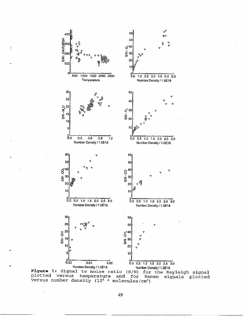
*
.
Vvz
- 500 1000 1500 2000 2500
Temperature
t______0.0 0.3 0.6 0.9 1.2
Number Density / 1.OE16
60 : v
50 : v
0“40 :V VP v
o‘ 30 :
G vC/J
10 :
0 ““’’’’’’’’””~0.0 0.5 1.0 1.5 2.0 2.5 3.0
Number Density/ 1.0E18
5Ltoo 0.01 0.02
‘160
50
0“40v
530 Vv0 v
20 v:
10
1.0 2.0 3.0 4.0 5.0 6.0
Number Density / 1.0E18
50 -
40 -
1“ 30 -
$co 20 -
0 40.0 0.5 1.0 1.5 2.0 2.5 3.0
Number Density / 1.0E18
vv
Vv
vv
; Vv
“v
60 -
50 :
040 : vo v
‘ 30 : vGco
20 ! V$
10 ?
0“”””’”’’’’’’’’”10.0 0.5 1.0 1.5 2.0 2.5 3.0
Number Density / 1.OE18
607
50 !’ v
=“ 40 : vo v
~ 30:V
20 \ Vv
10 :
0 --’’’’’’’’’”1 40.0 0.5 1.0 1.5 2.0 2.5 3.0
Number Density/ 1.0E18 Number Density / 1.OE18Figure 1: Signal to noise ratio (s/N) for the Rayleigh signalplotted versus temperature and for Raman signals plottedversus number density (106 * molecules/cm3)
49
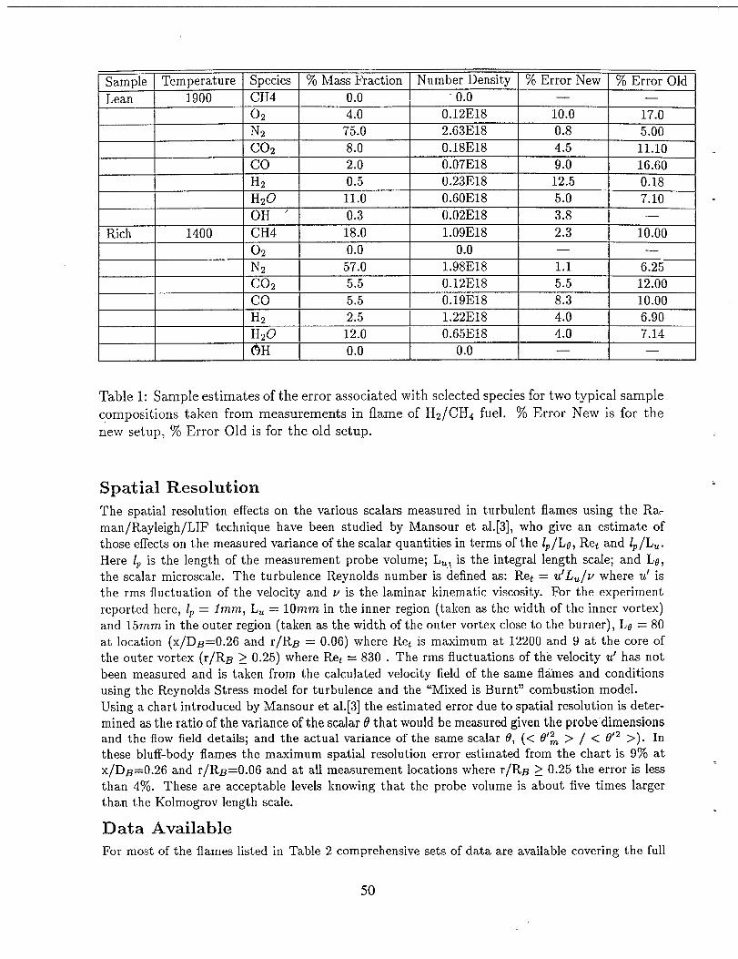
Sample Temperature Species VoMass Fraction Number Density % Error New 70 Error Old
Lean 1900 CH4 0.0 0.0 — —
o~ 4.0 0.12E18 10.0 17.0Nz 75.0 2.63E18 0.8 5.00C02 8.0 0.18E18 4.5 11.10 .
co 2.0 0.07E18 9.0 16.60Hz 0.5 0.23E18 12.5 0.18H20 11.0 0.60E18 5.0 7.10 “OH ‘ 0.3 0.02E18 3.8 —
Rich 1400 CH4 18.0 1.09E18 2.3 10.0002 0.0 0.0 — —
Nz 57.0 1.98E18 1.1 6.25C02 5.5 0.12E18 5.5 12.00co 5.5 0.19E18 8.3 10.00Hz 2.5 1.22E18 4.0 6.90
[ H~O 12.0 0.65E18 4.0 7.14
OH 0.0 0.0 — —
Table 1: Sample estimates Qf the error associated with selected species for two t ypical sample
compositions taken from measurements in flame of H2/CH4 fuel. 70 Error New is for the
new setup, $ZOError Old is for the old setup.
Spatial Resolution
The spatial resolution effects on the various scalars measured in turbulent flames using the Ra-
man/ Rayleigh/LIF technique have been studied by Mansour et al. [3], who give an estimate of
those effects on the measured variance of the scalar quantities in terms of the Zp/Le, Ret and Zp/Lti.
Here 1P is the length of the measurement probe volume; Lu, is the integral length scale; and LO,
the scalar microscale. The turbulence Reynolds number is defined as: Ret = u’Lu/v where u’ isthe rms fluctuation of the velocity and v is the laminar kinematic viscosity. For the experiment
reported here, 1P= 1mm, L. = 10rnm in the inner region (taken as the width of the inner vortex)
and 15mrn in the outer region (taken as the width of the outer vortex close to the burner), Lo = 80
at location (x/DB=0.26 and r/RB = 0.06) where Ret is maximum at 12200 and 9 at the core of
the outer vortex (r/Rjg ~ 0.25) where Ret = 830. The rms fluctuations of the velocity u’ has not
been measured and is taken from the calculated velocity field of the same flames and conditionsusing the Reynolds Stress model for turbulence and the “Mixed is Burnt” combustion model.
Using a chart introduced by Mansour et al.[3] the estimated error due to spatial resolution is deter-
mined as the ratio of the variance of the scalar (?that would be measured given the probe’ dimensionsand the flow field details; and the actual variance of the same scalar 6, (< d’: > / < 0’2 >). Inthese bluff-body flames the maximum spatial resolution error estimated from the chart is 970 atx/D~=O.26 and r/RB=0.06 and at all measurement locations where r/RB ~ 0.25 the error is less
than 4’XO.These are acceptable levels knowing that the probe volume is about five times largerthan the Kolmogrov length scale.
llata Available
For most of the flames listed in Table 2 comprehensive sets of data are available covering the full
50
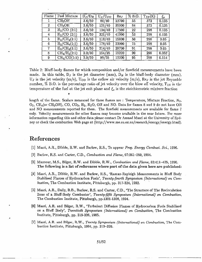
Flame Fuel Mixture DJ/DB uJ/uco ReJ % B.O. TIN(K) <81 CH30H 3.6/50 80/40 23700 55 373 0.1352 CH30H 3.6/50 121/40 35900 84 373 0.135, , , 1
3 ] Hz/CO (2:1) I 3.6;50 ] 134;40 I 17500 I 22 298 I 0.1351r , 1 I 1
4 I H2;coi2:li ! 3.6;50 I 321;40 1419901 53 298 I 0.135 I5 Hi;CHA(l:~) 3.6;50 118;40 15800 50 298 0.05
6 Hz/CH4(l:l) 3.6/50 178/40 23900 75 298 0.05,7 I Hq;CHdil:lj 3.6;50 I 214;40 I 287001 91 I 298 0.05 1,8 cH4/H2~2:l j 2.0;50 154;25 15200 90 298 0.052
9 CHAJCO(l:l) 2.0/50 99/25 12200 95 298 0.114
Table 2: Bluff-body flames for which composition and/or flowfield measurements have beel~
made. In this table, DJ is the jet diameter (mm), DB is the bluff-body diameter (mm),
UJ is the jet velocity (m/s), Uco is the coflow air velocity (m/s), Re~ is the jet Reynolds
number, 70 B. O. is the percentage ratio of jet velocity over the blow off velocity, TIN is t hc
temperature of the fuel at the jet exit plane and & is the stoichiometric mixture fraction
t
length of the flame. Scalars measured for these flames are : Temperature, Mixture Fraction, N2,02, CHA(or CH30H), CO, C02, H2, H20, OH and NO. Data for flames 8 and 9 do not have OHand NO measurements reported for them. The flowfield measurements are available for flame 7only. Velocity measurements for other flames may become available in the near future. For rnorcinformation regarding this and other data please contact Dr Assaad Masri at the University of Syd-ney or check the combustion Web page at (http: //www.me.su.oz. au/research/energy/energy.ht1lll).
.
References
[1]
[2]
[3]
[4]
[5]
[6]
[7]
Masri, A. R., Dibble, R.W. and Barlow, R. S., To appear Prog. Energy Condmst. Sci., 1996.
Barlow, R.S. and Carter, C. D., Combustion and Flame, 97:261-280, 1994.
Mansour, M. S., Bilger, R.W. and Dibble, R. W., Combustion and Flame, 82:411-425, 1990.The following is a list of references where part of the data given here are published:
Masri, A. R., Dibble, R.W. and Barlow, R. S., ‘Raman-Rayleigh Measurements in Bluff Body
Stabilised Flames of Hydrocarbon Fuels’, ~wenty-fourth Symposium ~lnternationalj on Comb-
ustion, The Combustion Institute, Pittsburgh, pp. 317-324, 1992. “’
Masri, A. R., Dally, B. B., Barlow, R.S. and Carter, C. D., ‘The Structure of The Recirculation
Zone of a Bluff-Body Combustor’, Twenty- fiflh Symposium (International) on Combustion,The Combustion Institute, Pittsburgh, pp.1301-1308, 1994.
Masri, A.R. and Bilger, R.W., ‘Turbulent Diffusion Flames of Hydrocarbon Fuels Stabilisedon a Bluff Body’, Twentieth Symposium (International) on Combustion, The Combustion
Institute, Pittsburgh, pp. 319-326, 1985.
Masri, A.R. and Bilger, R.W., Twenty Symposium (International) on Combustion, The Com-bustion Institute, Pittsburgh, 1984, pp. 319-320.
51/52

Blank Page
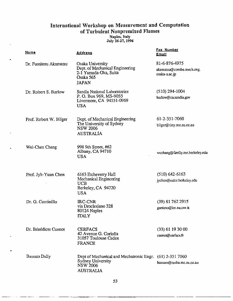
International Workshop on Measurement and Computation
.
Name
*
Dr. Fumiteru Akamatsu
Dr. Robert S. Barlow
Prof. Robert W. Bilger
,
. Wei-Chen Chang
Prof. Jyh-Yuan Chen
Dr. G. Continillo
Dr. B4n6dicte Cuenot
.
Bassarn Dally
of Turbulent Nonpremixed FlamesNaples,Italy
thI1y 26-27, 1996
Osaka UniversityDept. of Mechanical Engineering2-1 Yarnada-Oka, SuitaOsaka 565JAPAN
Sandia National LaboratoriesP. O. BOX 969, MS-9055Livermore, CA 94551-0969USA
Dept. of Mechanical EngineeringThe University of SydneyNSW 2006AUSTRALL4
998 9th Street, #62Albany, CA 94710USA
6163 Etcheverry HallMechanical Erq$neeringUCBBerkeley, CA 94720USA
IRC-CNRvia Droclesiano 32880124 NaplesITALY
CERFACS42 Avenue G. Coriolis31057 Toulouse CedexFRANCE
Dept of Mechanical and Mechatronic Engr.Sydney UniversityNSW 2006AUSTRALIA
53
F Numbec
&
81-6-876-4975
(510) 294-1004
61-2-351-7060
wcchrmg@f~efly.me.berkeley.edu
(510) 642-6163
(39) 817622915
(33) 61193000
(61) 2-3517060
[email protected],oz.au
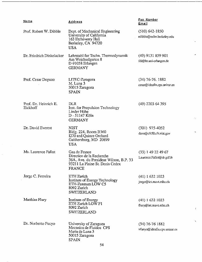
Nan.!2
Prof. Robert W. Dibble
Dr. Fnedrich Dinkelacker
Prof. Cesar Dopazo
Prof. Dr. Heinnch E.Eickhoff
Dr. David Everest
Ms. Laurence Fallot
Jorge C. Ferreira
Matthias Flury
Dr. Norberto Fucyo
Address
Dept. of Mechanical EngineeringUniversity of California163 Etcheverry HallBerkeley, CA 94720
USA
Lehrstuhl fur Techn. ThermodynamikAm Weichselgarten 8D-91058 ErlangenGERMANY
LITEC-ZaragozaM. Luna 350015 ZaragozaSPAIN
DLRInst. for Propulsion TechnologyLinder HoheD -51147 Koln
GERMANY
NISTBldg. 224, Room B3601270 and Quince OrchardGaithersburg, MD 20899USA
Gaz de FranceDirection de la Recherche36A, Ave. du President Wilson, B.P. 3393211 La Plaine St. Denis CedexFRANCE
ETH ZurichInstitute of Energy TechnologyETH-Zentrum LOW C58092 ZurichSWITZERLAND
Institute of EnergyETH Zurich LOW F18092 ZurichSWITZERLAND
University of ZaragozaMecanica de Fluidos CPSMaria de Luna 350015 ZaragozaSPAIN
54
Fax NumbeC
&rtdl
(510) 642-1850
(49) 9131859901
(34) 76-76.1882
(49) 220364395
(301) 975-4052
(33) 149224967
(419 16321023
(41) 16321023
(34) 76-761882
nfue@i&afix.cps.unizar.es
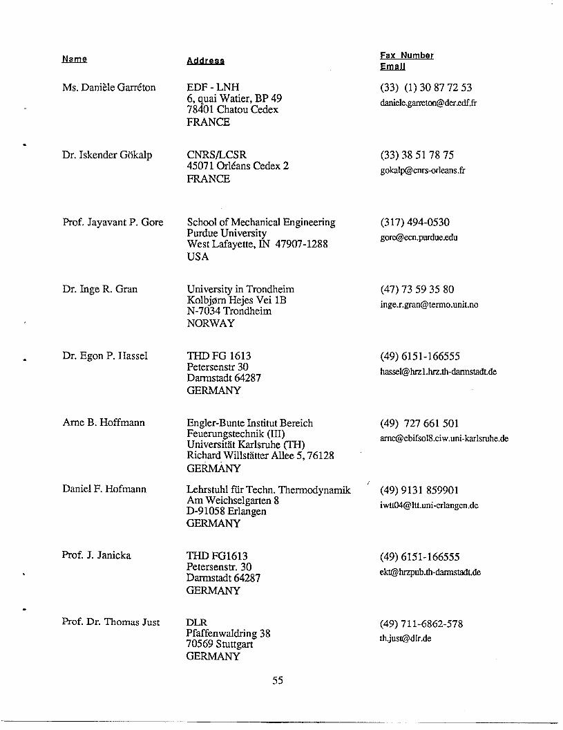
Name
Ms. Dani?le Garr6ton
●
Dr. Iskender Gokalp
Prof. Jayavant P. Gore
Dr. Inge R. Gran
●Dr. Egon P. Hassel
Ame B. Hoffmann
Daniel F. Hofmann
Prof. J. Janicka
*
.
Prof. Dr. Thomas Just
EDF - LNH6, quai Watier, BP 4978401 Chatou CedexFRANCE
CNRS/LCSR4507 10r16ans Cedex 2FRANCE
School of Mechanical EngineeringPurdue UniversityWest Lafayette, IN 47907-1288USA
University in TrondheimKolbj@m Hejes Vei lBN-7034 TrondheimNORWAY
THD FG 1613Petersenstr 30Darrnstadt 64287GERMANY
Engler-Bunte Institut BereichFeuerungstechnik (III)Universitat Karlsruhe (TH)Richard Willstatter Allee 5,76128
GE-
Lehrstuhl fur Techn. ThermodynamikAm Weichselgarten 8D-91058 ErlangenGERMANY
THD FG1613Petersenstr. 30Darrnstadt 64287GERMANY
DLRPfaffenwaldring 3870569 StuttgartGERMANY
Fa NumbeC
&
(33) (1) 30877253
(33) [email protected]
(317) 494-0530
(47) 73593580
(49) 6151-166555
(49) 727661501
(49) 9131859901
(49) 6151-166555
(49) 711-6862-578
th.@@dir.de
55
Fax Number
(202) 767-4798
Name
Dr. Carolyn R. Kaplan
Address
Code 6410Naval Research LaboratoryWashington, DC 20375USA
Dr. Viswanath R. Katta 1SS13845 Woodhurst CourtDayton, OH 45430USA
(513) 255-3139 .
[email protected]. wpafb.af.mil
Dr. Masaharu Komiyama Dept. of Mechanical EngineeringOsaka University
81-6-879-7311
[email protected], Yamada-Oka, Suita
Osaka, 565JAPAN
Markus Kraft FB CheminUniversitat KaiserslauterrtD67663 KaiserslautemGERMANY
(49) 6312052187
Guenther C. Krieger TH DarmstadtFachgebiet Energie-und KraftwerkstechnikPetersenstr. 30Darmstadt 64287GERMANY
(49) 6151-166555
Prof. Bernhard Lenze Engler-Bunte-Institut, Univ. KarlsruheKaiserstr. 12
(49) 721-661501
[email protected] Karlsruhe
GERMANY
Dr. R. P. Lindstedt Mechanical Engineering Dept.Imperial CollegeExhibition RoadLondon SW72BXUK
(44) 171-8238845
Prof. Marshall Long Yale UniversityMechanical EngineeringP.O. BOX208284New Haven, CT 06520USA
(203) 432-6775
Chnstoph Magel University of Stuttgart -NDPfaffenwaldring 2370550 StuttgartGERMANY
49-711-6853491
56
J!&un!2
Gaudenzio Mariotti
.
Prof. Assaad R. Masri
Dr. Wolfgang Meier
Akira Miyafuji
* Pieter A. Nooren
Michael Oevermann
Dr. Tae Won Park
Dr. T.W.J. Peeters
.
.
Prof. Dr. Norbert Peters
Fax NumbeL
&?lfLU
ENEL (39) 50-535021Centro Ricerca Termica [email protected] Andrea Pisano 12056122 PissrI’ALY
Dem. of Mechanical and Mechatronic Enzr. (61) 2-3517060
[email protected] University“.,
NSW 2006AUSTRALIA
DLR - Institut fur Physikalische Chemieder VerbrennungPfaffenwaldring 3870569 StuttgartGERMANY
Dept. of Mechanical EngineeringOsaka University2-1 Yamada-Oka, SuitaOsaka, 565JAPAN
Delft University of TechnologyHeat Transfer SectionP.O. BOX 50462600 GA DelftTHE NETHERLANDS
DLR Institut fiir StromungsmechanikBunsenstr. 1037073 GottirtgenGERMANY
Wright Laboratory, WL/POSCRoom 104, Building 490, Area B1790 Loop Road NorthWright Patterson AFB, OH 45433-7103USA
Delft University of TechnologyHeat Transfer Section, Faculty of Appl.Phys.Lorentzweg 1
~ titiRLANDS
Institut fii Technische MechanikRWTH AachenD52056, AachenGERMANY
(49) 7116862578
81-6-879-7311
(31) 15.2781204
(49) 55517092446
(513) [email protected] .wpafb.af.mil
(31) 15.2781204
(49) 2418888223
57
JNamQ
Dr. William M. Pitts
Prof. Robert W. Pitz
Prof. Stephen B. Pope
Dr. Larry A. Rahn
Prof. Dr. Dirk Roekaerts
Dr. Hans Sanders
Thomas Schafer
Martin Schlatter
Prof, Mitchell D. Smooke
Address
B258/224National Institute of Standards&TechnologyGaithersburg, MD 20899USA
Vanderbilt UniversityMechanical EngineeringBox 1592, Station BNashville, TN 37235USA
Upson HallCornell UniversityIthaca, NY 14853USA
Sandia National LaboratoriesP. O. BOX969, MS9056Livermore, CA 94551-0969USA
Shell Research & Technology CentreP. O. BOX 380001030 BN AmsterdamTHE NETHERLANDS
LCSR-CNRS OrleanslC, Ave. de la Recherche Scientifique4507 10rleans Cedex 2FRANCE
Universitat HeidelbergPhysikalisch-Chemisches InstitutIm Neuenheimer Feld 25369120 HeidelbergGERMANY
ETH ZurichInstitute of Energy TechnologyETH Zentrum LOW C28092 ZurichSWITZERLAND
Dept. of Mechanical EngineeringYale UniversityNew Haven, CT 06520
USA
Fax Number
!ana
(301) 975-4052
(615) 343-8730
(607) 255-1222
(510) 294-2276
(31) 206304035
(33) 38.51.78.75
(49) 6221544255
(41) 16321023
[email protected]. ethz.ch
-:(203) 432-6775
smooke%[email protected]
58
Jwn!2 &!m!2ssFax N rnberEm@Jl”
Markus M. Tacke TH - Darmstadt (49) 6151166555Energie-und KraftwerkstechnikPetersenstrasse 30
D64287 DarmstadtGERMANY
*Prof. Toshimi Takagi Osaka University
Dept. of Mechanical Engineering2-1, Yamada-Oka, SuitsOsaka 565
(81) 6-879-7311
JAPAN
Dr. Fumiaki Takahashi University of Dayton (513) 252-9917300 College ParkDayton, OH 45469-0140
USA
Frank Tichy University in TrondheimKolbj@rn Hejes Vei lBN-7034 Trondheim
(47) 73593580
* NORWAY
Dr. Th. H. van der Meer Delft University of Technology●
(31) 15-2781204Dept. of Applied Physics, Heat TransferSect.
P.O. BOX 5046
~ tititiANDS
Prof. Forman A. Williams Ames 0411 (619) 534-5354University of California, San DiegoLa Jolla, CA 92093
USA
Huib A. Wouters Delft University of TechnologyHeat Transfer SectionP. O. BOX5046
(31) 15-2781204
2600 GA DelftTHE NETHERLANDS
Dr. Bernard Zamuner oNERA (33-1) 46734147Energetic DepartmentBP72
zamunemonera.fr
92322- Chatillon CedexFRANCE
59/60

Blank Page
International Workshop on Measurement and Computationof Turbulent Nonpremixed Flames
Su mmarv of workshoD Acco mt)]ishment~
July 27, 1996
Sixty-one people from eleven countries participated in this workshop, which was marked byactive discussions and a strong consensus that the collaborative efforts proposed by thisworkshop will be valuable. The primary objectives of the workshop were achieved, namelythe selection of a few well-documented flames to serve as a first round of standard cases, thespecification of common submodels to be used (where appropriate) in model calculations ofthese standard flames, and the definition of some ground rules for comparison of modelresults.
On the second day of the workshop, four discussion groups were formed to providerecommendations on specific issues.
Qm12 Leaders
Experimental Data Sets Hassel, MasriTurbulence Models and Radiation Janicka, GoreMixing Models and Reduced Chemistry Pope, Dopazo“Standard” Flames of the Future Bilger
The recommendations of these groups are outlined on the following pages, which include thenames of those people who have kindly agreed to serve on committees or complete certaintasks.
It was agreed that opportunities for new funding to support this international collaborativeresearch effort should be explored. A committee comprised of Bilger, Barlow, Gokalp,Janicka, Just, Pope, and Rahn will pursue strategies for approaching funding agencies.
It was also agreed that more workshops on this topic should be held. Initial plans are to have awork-in-progress workshop in one year, possibly at Sandia/California. The committee listedabove will investigate opportunities to obtain travel funding, and they will also look into thepossibility of holding the work-in-progress workshop in conjunction with and appropriateturbulence or combustion meeting during the summer of 1997. A pre-27 th-SymposiumWorkshop on Measurement and Modeling of Turbulent Nonpremixed Flames will be plannedfor Boulder, Colorado in 1998.
Information generated through this workshop and the ongoing collaborations will be madeavailable through the Web site that has already been established for the workshop. This willinclude:● descriptions of the selected data sets and links to sites where the data are available“ links to other data sets for nonpremixed flames that are available but have not been selected
for this first round of comparisonse information on recommended submodels, and “reference” calculations for some of the
standard flames.The committee for the Web site will be: Hassel, Meier, Barlow, Pope, Masri, Gore, Lindstedt
It is anticipated that the results of these collaborative comparisons, together with descriptions ofthe data sets, will be published in an edited volume and should make a significant contributionto the archival combustion literature.
61
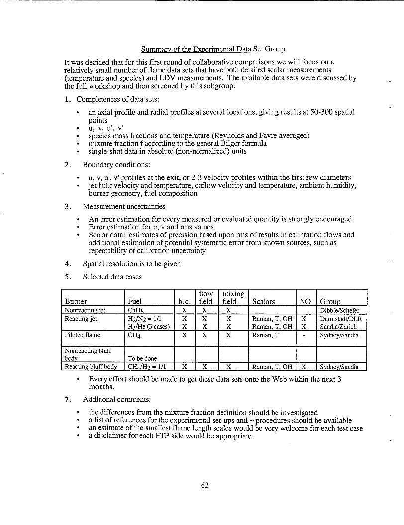
Summary of the ExDerimental Data Set Grouu
It was decided that for this fiist round of collaborative comparisons we will focus on arelatively small number of flame data sets that have both detailed scalar measurements(temperature and species) and LDV measurements. The available data sets were discussed bythe full workshop and then screened by this subgroup.
1. Completeness of data sets:
● an axial profde and radial profiles at several locations, giving results at 50-300 spatialpoints
● u, v, u’, v’“ species mass fractions and temperature (Reynolds and Favre averaged)● mixture fraction f according to the general Bilger formula● single-shot data in absolute (non-normalized) units
2. Boundary conditions:
● u, v, u’, v’ profiles at the exit, or 2-3 velocity profiles within the first few diameters● jet bulk velocity and temperature, coflow velocity and temperature, ambient humidity,
burner geometry, fuel composition
3. Measurement uncertainties
● An error estimation for every measured or evaluated quantity is strongly encouraged.● Error estimation for u, v and rrns values● Scala data estimates of precision based upon rms of results in calibration flows and
additional estimation of potential systematic error from known sources, such asrepeatability or calibration uncertainty
4. Spatial resolution is to be given
5. Selected data cases
flow mixingBurner Fuel b.c. field field Scalars NO GroupNonreactingjet C?H8 x x x Dibble/ScheferReactingjet H2/N2= 1/1 x x x Raman, T, OH x Darmstadt/DLR
H#He (3 cases) x x x Raman, T, OH x SandiaZurichPilotedflame cm x x x Raman, T - SydneylSandia
Nonreactingbluffbody To be doneReactingbluffbody CH4/HZ= 1/1 x x x Raman, T, OH x SydneylSandia
● Every effort should be made to get these data sets onto the Web within the next 3months.
7. Additional comments:
● the differences from the mixture fraction definition should be investigated● a list of references for the experimental set-ups and - procedures should be available● an estimate of the smallest flame length scales would be very welcome for each test casee a disclaimer for each FIT side would be appropriate
62
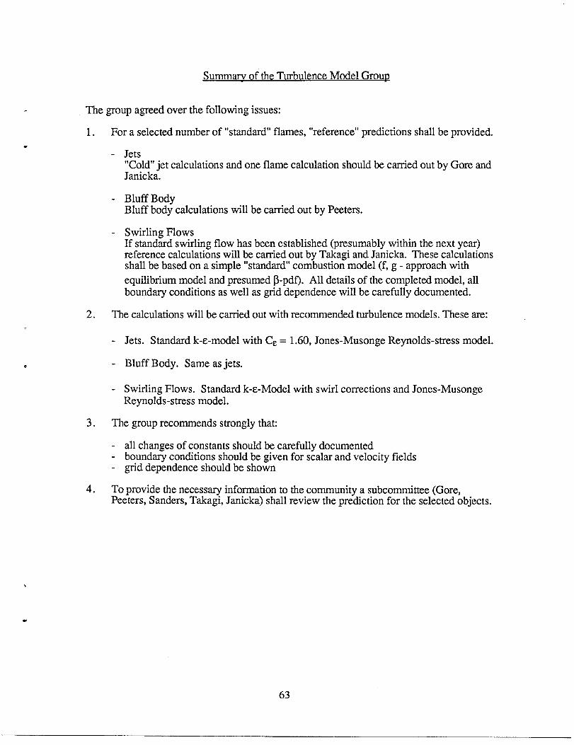
Summarv of the Turbulence Model Grou~
The group agreed over the following issues:
1. For a selected number of “standard” flames, “reference” predictions shall be provided.
- Jets“Cold” jet calculations and one flame calculation should be carried out by Gore andJanicka.
- Bluff BodyBluff body calculations will be carried out by Peeters.
- Swirling FlowsIf standard swirling flow has been established (presumably within the next year)reference calculations will be carried out by Takagi and Janicka. These calculationsshall be based on a simple “standard” combustion model (f, g - approach with
equilibrium model and presumed ~-pdf). All details of the completed model, allboundary conditions as well as grid dependence will be carefully documented.
2. The calculations will be carried out with recommended turbulence models. These are:
- Jets. Standard k-e-model with C~ = 1.60, Jones-Musonge Reynolds-stress model.
- Bluff Body. Same as jets.
- Swirling Flows. Standard k-e-Model with swirl corrections and Jones-MusongeReynolds-stress model.
3. The group recommends strongly that
all changes of constants should be carefully documented- boundary conditions should be given for scalar and velocity fields- grid dependence should be shown
4. To provide the necessary information to the community a subcommittee (Gore,Peeters, Sanders, Takagi, Janicka) shall review the prediction for the selected objects.
63
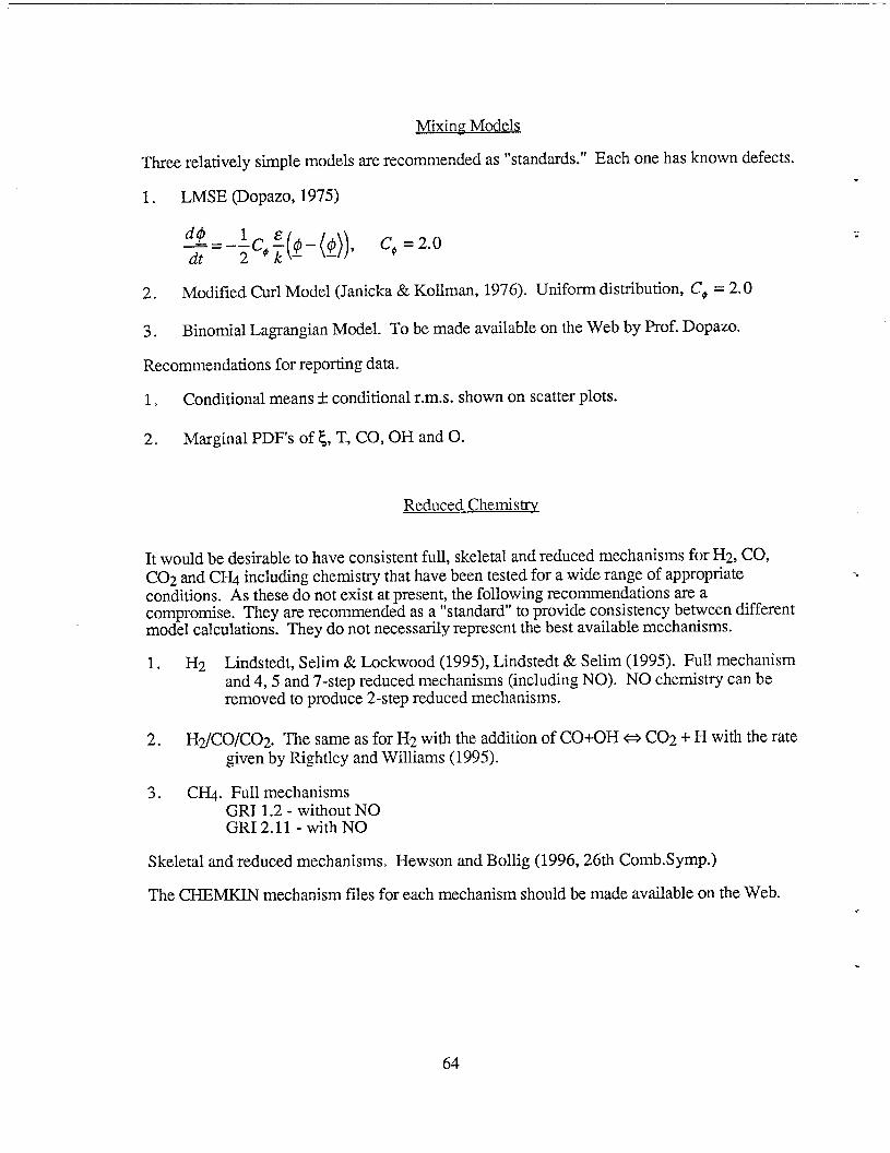
Mixing ModeIs
Three relatively simple models are recommended as “standards.” Each one has known defects.
1. LMSE (Dopazo, 1975)
2. Modified Curl Model (Janicka & Kollman, 1976). Uniform distribution, CO =2. O
3. Binomial Lagrangian Model. To be made available on the Web by Prof. Dopazo.
Recommendations for reporting data.
16 Conditional means * conditional r.m.s. shown on scatter plots.
2. Marginal PDFs of ~, T>CO, OH and 0.
Reduced Chemistry
It would be desirable to have consistent full, skeletal and reduced mechanisms for Hz, CO,C02 and CH4 including chemistry that have been tested for a wide range of appropriateconditions. As these do not exist at present, the following recommendations are acompromise. They are recommended as a “standard” to provide consistency between differentmodel calculations. They do not necessarily represent the best available mechanisms.
1. Hz Lindstedt, Selim & Lockwood (1995), Lindstedt & Selim (1995). Full mechanismand 4, 5 and 7-step reduced mechanisms (including NO). NO chemistry can beremoved to produce 2-step reduced mechanisms.
2. H2/CO/C02. The same as for Hz with the addition of CO+OH ~ C02 + H with the rategiven by Rightley and Williams (1995).
3. CI&. Full mechanismsGRI 1.2- without NOGRI 2.11- with NO
Skeletal and reduced mechanisms. Hewson and Bollig (1996, 26th Comb. Symp.)
The CHEMKIN mechanism files for each mechanism should be made available on the Web.
.
64
Re~ort on Radiation
Thermal radiation from flames reduces the local temperatures sufficiently to affect theproduction rates of pollutants such as NO. In order to include this effect into turbulence-chemistry models for simple jet diffusion flames, a highly simplified treatment of radiative heatloss is needed.
The flames selected for baseline model evaluation and development involve Hz, H~2 andHfie mixtures injected in the fuel stream. This simplifies the radiation calculations, sinceonly H20 bands are involved. Radiative heat loss is a nonlinear function of waterconcentration and temperature; hence, the fluctuations lead to turbulence-radiation interactions.Therefore, average temperatures and average concentrations cannot be used. Mean radiativeheat loss (optically thin) can be calculated using integration of a source term convoluted with ajoint probability density function of appropriate scalars such as mixture fraction and enthalpy.It is important to note that this PDF should be time averaged thus increasing the temperaturedependence.
The Planck mean emission coefficient should be used to calculate optically thin (emission only)radiative heat loss. The RADCAL program by Grosshandler of NIST is most convenient forgenerating the Planck mean absorption coefficient data.
A list of references on coupled radiation and turbulence calculations is being assembled.Contributions to this list from workshop participants and others are welcome.
The action items are:
1) Measurements of radiative heat fluxes for the Sandia/Darmstadt H#air and Hz + He/airflames, and CO/H2/NZ flames. Gore and Barlow have made preliminary arrangements tomake these measurements within the next 3-6 months.
2) Reference coupled calculations on the Web for the Darmstadt “H3” flames.
65
Grouu Re~ort on “Standard” Flames of the Future
Introduction
Our views became focussed after agreeing on the following premises:
● Improvements in modeling the effects of turbulence on chemistry will remain aleading edge issue for some time (at least 3 years).
● The spontaneous Raman probe will remain a unique measurement tool that enablesmixture fractions to be determined in conjunction with reactive scalars.
● Recommendations should not over-reach the likely capabilities of experimentersand/or modellers.
Jet Flames
Unpiloted and piloted jet diffusion flames should continue to be a major thrust ofexperiments within the following as examples of what should be worthwhile.
“ completion of databases on intermediate fuels such as HJCO and HiCOz with goodmeasurements of CO, NO and radiation loss.
● use of the now identified “standard” H~2, flames as a base from which morecomplex kinetics can be studied by addition of small amounts of NH3, methylamine(source for HCN), CILI, etc. The aim is to test modeling capability for secondaryreactions occurring at equivalence ratios of 2 to 3 and hence quite separate from themain reaction zone.
* use of the now identified standard H2/N2 flames as a basis for investigation byadvanced techniques such as 2D/3D imaging and as a calibration for otherdiagnostics.
Jets into Hot Coflow
Development of new experimental configurations involving a simple jet in a coflow ofhot combustion products in geometries accessible to spontaneous Raman measurementsshould be pursued. They will provide better simulations of the reaction/mixingsituations inherent in:
o recirculation zones where fuel mixes with products rather than air (Dibble)
● NOXreburn where methane is injected into (cooled) near-stoichiometric combustionproducts
Confined Axisymmetric Flows
There is a need to prove turbulent chemistry modeling in “elliptic” flows. Confinedflows will be more realistic simulations of industrial combustors than bluff-body flowsin a surrounding unconfined airstream. Accessibility for spontaneous Ramanmeasurements is essential. Swirling flows to be included. Data will also be importantfor improving flow and mixing models.
66
INITITAL DISTRIBUTIONUNLIMITED RELEASE
Dr. Wiliam H. KirchhoffU.S. Department of EnergyER 141, G-236Office of Basic Energy SciencesWashington, DC 20545
Dr. Allan H. LauferU.S. Department of EnergyG-340, ER-141Washington, DC 20545
Dr. Robert S. Marianelli, DirectorDivision of Chemical SciencesOffice of Basic Energy SciencesU.S. Department of Energy, ER 14, GTNWashington, DC 20545
Prof. Marcus AldenLund Institute of TechnologyCombustion CentreP.O. BOX 1189S-221 00 LundSWEDEN
Dr. Frank BehrendtUniversitat Heidelberg - I W RIm Neuenheimer Feld36869120 HeidelbergGERMANY
Prof. K.N.C. BrayCambridge UniversityEngineering DepartmentTrumpington StreetCambridge CB2 lPZENGLAND
Prof. Sebastien CandelEcole Centrale de ParisGrande Voie des Vignes92295 Chatenay Malabry cedexFRANCE
Prof. Norman ChigierCarnegie Mellon UniversityMechanical EngineeringPittsburgh, PA 15213-3890
Prof. Werner J.A. DahmUniversity of MichiganAerospace Engineering #21 18Ann Arbor, MI 48109-2118
Prof. Gerard M. FaethDept. of Aerospace EngineeringUniversity of Michigan3000 FXB BuildingAnn Arbor, MI 48109-2118
Prof. Ahmed GhoniemMassachusetts Institute of Technology77 Massachusetts AvenueCambridge, MA 02319
Prof. W. P. JonesImperial CollegeChemical EngineeringPrince Consort RoadLondon SW72BYUK
Prof. Wolfgang KollmannDepartment of Mechanical EngineeringUniversity of CaliforniaDavis, CA 95616
Dr. Ulrich MaasKonrad-Zuse-Zentrum fuerInformationstechnikHeilbronner Str. 1010711 Berlin-WilmersdorfGERMANY
Prof. Bjom MagnussenInst. for TermodynamikNHTN7034 TrondheimNORWAY
Dr. George KosalyDepartment of Mechanical EngineeringUniversity of Washington, FU-10Seattle, WA 98195
Dr. Mohy S. MansourMechanical Power Engineering Dept.Cairo UniversityGinEGYPT
67
Prof. Suresh MenonSchool of Aerospace EngineeringGeorgia Institute of TechnologyAtlanta, GA 30332-0150
Dr. Bernd RoggRuhr-Universitat BochumInst. fur Therrno. und Fluid.Universitatsstr 15044780 BochumGERMANY
Dr. Winfried StrickerDLRInst. fur Phys. Chemie der VerbrennungPfaffenwaldring 3870569 StuttgartGERMANY
Prof. Juergen WolfrumRuprecht-Karis-UniversitatPhysikalisch Chemisches Inst.Im Neuenheimer Feld 25369120 HeidelbergGERMANY
Dr. M. S. AnandAllison Gas Turbine DivisionGeneral Motors CorporationP.O. Box 420, Speed Code T-1Indianapolis, IN 46206-0420
Dr. Roland BorghiLMFN, CORIAURA CNRS 230INSA de RouenBP8 76131 Mont Saint AignanFRANCE
Dr. Campbell D. CarterSystems Research Laboratory2800 Indian Ripple RoadDayton, OH 45440-3696
Dr. Yung-cheng Chen101, Sec. 2, Kuang Fu RoadHsinchu 30043TaiwanREPUBLIC OF CHINA
Dr. Sanjay CorreaGeneral Electric R&D CenterP.O. BOX 8, K1-ES112Schenectady, NY 12301
Mr. G. B. Drummond567 South L StreetLivermore, CA 94550
Dr. Hukam MongiaGeneral Electric Aircraft EnginesMD X403One Neumann WayCincinnati, OH 45215-6301
Dr. Elaine S. OranNaval Research LaboratoryCode 64044555 Overlook AvenueWashington, DC 20375-5433
Dr. Robert V. SerauskasGas Research Institute8600 W. Bryn Mawr AvenueChicago, IL 60631
Dr. Julian M. TishkoffAFOSRINA110 Duncan Avenue, Suite B 115Boiling AFB, DC 20332
MS9001Attn:
MS9054Attn:
MS9042MS9057MS9021
MS9021
MS0899MS9018
68
T. O. Hunter, 8000MS9005 J. B. Wright, 2200MS9006 E. E. Ives, 5200MS9004 M. E. John, 8100MS9420 L. A. West, 8200MS9007 R. C. Wayne, 8400MS9002 P. N. Smith, 8500MS9405 T. M. Dyer, 8700MS9141 P. E. Brewer, 8800MS9003 D. L. Crawford, 8900W. J. McLean, 8300MS9056 J. C. McMichael, 8305MS9671 D. W. Putz, 8346MS9056 L. A. Rahn, 8351MS9055 F. P. Tully, 8353MS9052 D. R. Hardesty, 8361MS9053 R. W. Carling, 8362MS9053 R. J. Gallagher, 8366A. E. Lutz, 8345R. S. Barlow. 8351 (15)Technical Co~unicationsDepartment, 8815, for OSTI (10)
.-
Technical CommunicationsDepartment, 88151TechnicalLibrary, MS 0899,4414
$,
Technical Library, 4414 (4)Central Technical Files, 8940-2 (3)