Embed Size (px)
Citation preview

PROCEEDINGS PAPER
A Study of Stress Relaxation in Prestressing Reinfor(ement
by Donald D. Magura, Mete A. So,zen, Chester P. Siess*
INTRODUCTION
Relaxation is defined as the loss of stress in a stressed material held at constant length. Another manifestation of the same basic phenomenon, creep, is defined as the change in length of a material under stress. Since no generally satisfactory quantitative relationship between creep and relaxation has been developed, relaxation tests must be carried out whenever relaxation data are required, although creep tests are simpler to perform.
Relaxation characteristics of prestressing reinforcement are of interest in prestressed concrete construction, even though pure relaxation does not exist under practical conditions. Creep and shrinkage of the concrete and fluctuations in superimposed load change the length of the tendon. Nevertheless, the tendon does not deform freely and the stress in it can change. Thus, the conditions are comparable more to a relaxation test than to a creep test.
The attitude toward the effect of relaxation has changed considerably over the last two decades. At first, relaxation losses were considered to be quite critical because they affected the working stresses which governed the design. At the same time, it was thought that the reinforcement reached a stable stress in a matter of a few weeks if not hours and that the relaxation losses were limited to a very small fraction of the initial stress. By the time it was established that relaxation losses could amount to as much as 20 percent of the initial stress over a long period of time, it was recognized that partial loss of prestress is not necessarilly accompanied by a loss in flexural strength.
At present, a knowledge of the losses resulting from relaxation is required primarily in relation to the serviceability of a prestressed member. In this respect, it should be mentioned that the critical quantity is the remaining stress and not the loss. The recognition of this fact makes a considerable difference in the interpretation of the available test data.
Object and Scope
The object of this paper is to present and evaluate the results of available relaxation tests with a view to the development of expressions for estimating the effects of stress relaxation.
Appendix A presents a detailed
description of 57 tests carried out at the University of Illinois.
Appendix B summarizes the results of 444 tests carried out in the course of 17 investigations at different laboratories.
The data from all 501 tests are
"Assistant Development Engineer, Portland Cement Association, Professor of Civil Engineering, University of Illinois, and Professor of Civil Engineering, University of Illinois, respectively.
April 1964 13
discussed in the paper which includes a bibliography on stress relaxation.
Definitions
Yield Stress: 0.1 percent offset stress
Initial Stress Ratio: Initial stress/ yield stress
Final Stress Ratio: Final stress/ initial stress
METHODS OF STRESS MEASUREMENT A relaxation test requires equip
ment which will determine the stress in the specimen while keeping the strain constant. The necessity for long durations of tests under controlled environment puts practical limits on the size of the specimen and related equipment. These criteria have been satisfied or nearly satisfied by various investigators using different methods which can be categorized in four groups and are described briefly in the following sections.
The Vibration Method
The vibration method involves the determination of the stress in the wire by measuring its frequency of lateral vibration. It was used first by Dawance [1948].
The measured frequency of vibration is converted to stress with the use of a calibration for a given mode of vibration obtained prior to the relaxation test. This method makes it possible to use rather short lengths of specimens since the stress is measured without any appreciable movement of the anchorages. Wires with a length to diameter ratio of approximately 200 have been used in tests.
One application of the vibration method is described in detail in Appendix A.
14
The Lever Method
Some investigators stressed the wires through a lever system which made it possible to use relatively small weights to develop the necessary stress in the wire. The length of the specimen was maintained constant by removing the weights as it became necessary.
Variations of this system were used by Bannister [1953], the C.U.R. [1958], Kajfasz [1958] and others.
The Balance Method
The characteristic of this method is the determination of the stress in the wire by balancing, temporarily, the tension in the wire by a known force. One end of the wire is gripped and pulled until the reaction of the near anchorage is zero. The measured force corresponding to this condition is the tension in the wire.
Magnel [1948] and Spare [1952] used this method with different mechanical arrangements.
Closely allied to this method is the one involving direct measurement of the force (Bate [1958] and Kingham [1961]) with the use of a dynamometer in series with the wire. To give an indication of the change in stress, the dynamometer has to deform. However, this deformation can be arranged to be small in relation to the length of the specimen so that the change in strain in the specimen is very small.
The Deflection Method
The deflection method, used by Gifford [1953], involved the determination of the stress in the wire by measuring its lateral deflection at mid-length under a known load. The relation between the force in the wire and the lateral deflection
PCI Journal
'+-0 'Q)
..c E ::J z
10
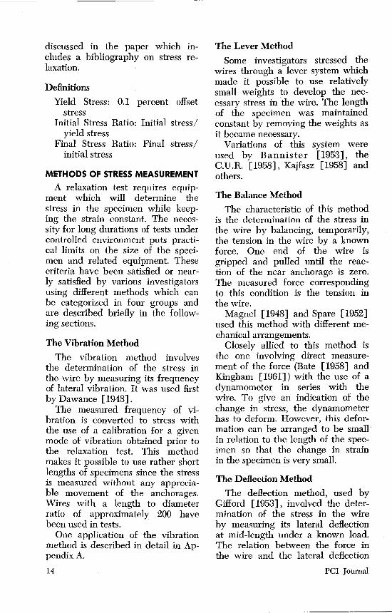
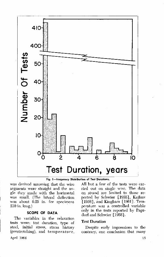
Test Duration, years Fig. !-Frequency Distribution of Test Duratio,ns.
was derived assuming that the wire All but a few of the tests were car-segments were straight and the an- ried out on single wire. The data gle they made with the horizontal on strand are limited to those re-was small. (The lateral deflection ported by Schwier [1955], Kajfasz was about 0.25 in. for specimens [1958], and Kingham [1961]. Tem-210 in. long.) perature was a controlled variable
SCOPE OF DATA only in the tests reported by Papsdorf and Schwier [1958].
The variables in the relaxation tests were: test duration, type of steel, initial stress, stress history (prestretching), and temperature.
April 1964
Test Duration
Despite early impressions to the contrary, one conclusion that many
15

r I
investigators have come to is that the phenomenon of relaxation is not shortlived. It appears from the available evidence that relaxation may continue indefinitely although at a diminishing rate. Consequently, the significance of a given test depends on its duration.
As indicated earlier, this report draws information from 501 individual tests, an impressive number. However, the impact of this number is reduced when the durations of these tests are considered. Figure 1 shows the number of tests for different test durations grouped in half-year intervals. Only 18 percent of the 501 tests exceeded a duration of one-half year. A total of 36 tests exceeded a duration of 3 years and only 15 tests exceeded 6 years. Of these 15 tests, 8 were reported by Levi [1958] and 7 are described in Appendix A of this report.
It is hoped that a breakthrough will be made in the technique of relaxation tests by the achievement of a reliable understanding of the time-temperature interaction. Longtime losses at working stress and temperature levels can then be estimated closely by short-time tests under high temperatures and/ or stresses. However, the final confirmation of any such procedure may have to await the development of long-time data under ordinary conditions.
Type of Steel
All tests discussed in this report have been carried out on colddrawn wire which is produced from billets of high-carbon steel usually in three steps: hot-rolling, lead patenting, and cold-drawing. Billets are first hot-rolled into rods. To give them the ductility and strength re-
16
quired in the cold-drawing process, they are heated to a temperature sufficient to transform the grain structure of the steel and then cooled in a lead bath to arrest the grain structure in the sorbitic stage. Following this process, the rods are drawn through dies of successively smaller size to the desired diameter. The drawing operation tends to decrease the ductility and increase the strength of the wire.
Frequently, the wire is subjected to further treatment to produce additional changes of the physical properties. The most common treatments employed are: stress-relieving, oil tempering, and straightening.
Stress-relieving is a controlled time-temperature heat-treatment process. It consists of heating the wire for a short period of time to temperatures in the range of 500oF to IOOOoF; the time and tempera·· ture being varied to remove the residual stresses without destroying the fibrous grain structure. The process produces a wire with increased elastic limit and ductility over the as-drawn wire.
Oil tempering is a heat-treatment process in which the fibrous structure is destroyed by heating the wire to about 1700°F, quenching it in an oil bath and immersing it in lead at about 800°F. The elastic limit is increased by this process, but ductility remains low.
Drawn wire retains a high degree of curvature when wound on a reel directly from the wire drawing block. The radius of curvature is small making the wire difficult to handle. Therefore, it is mechanically straightened to increase the free radius. Wire which has been heat-treated generally has a free radius greater than as-drawn wire
PCI Journal

since the heat-treating equipment uses larger diameter reels. Because the free radius is sufficiently large, heat-treated wire is not usually straightened.
The tests described were made on wires subjected to various types of treatment subsequent to drawing. The pertinent information, wherever available, is given in detail in Appendices A and B. About threefourths of the total number of tests were conducted on wire in the asdrawn condition.
Initial Stress
The absolute value of the initial stress is not significant in studying data from wires having diHerent stress-strain characteristics. The ratio of the initial stress to the 0.1-percent offset stress was chosen as a comparison index in this study.
Figure 2 shows the frequency distribution of the ratio of the initial stress to the 0.1-percent offset stress for 228 tests for which the 0.1-percent offset stress was available. The range extends from 0.29 to 1.44. However, 86 percent of the data lie between 0.5 and 1.0. Although the 0.1-percent offset stress is not given for a substantial portion of the data reported, it appears from the other strength information provided that the picture presented in Fig. 2 is representative of the whole group of data.
Prestretching
Prestretching involves the appli-
Source
Dumas Kajfasz Gifford Appendix A
April 1964
Stress
0 to 50% above initial stress 10% above initial stress 12 ksi above initial stress 10% above initial stress
cation to the wire of a sustained stress equal to or greater than the initial stress for a short period of time prior to anchoring the wire. It is intended to reduce relaxation losses.
A number of investigations included prestretched specimens to determine the effect of this variable on relaxation losses. Since the operation has not been standardized, tests were conducted on specimens prestretched for various lengths of time and at various amounts of stress as shown in the table at the bottom of this page.
Tests were conducted on prestretched wires with non-prestretched companion specimens to allow evaluation of the effect of prestretching on relaxation losses.
DISCUSSION OF DATA ON STRESS RELAXATION
Effect of Initial Stress To illustrate the effect of initial
stress on relaxation losses, the data from Series SR100 reported in Appendix A are plotted in Fig. 3. The loss is shown as a function of the initial stress. All data refer to the same type of wire.
The curve in Fig. 3, drawn merely to show the trend, indicates that as the initial stress increases, the loss increases at an increasing rate. This trend was representative of all available test results.
As mentioned earlier, it is not possible to compare data from different types or even shipments of
~No. of Prestretched Time Specimens
2 minutes 10 minutes 2minutes
10 or 15 minutes
20 11 5
16
52
17

40
(/) ..... (/)
~ 30
'+-0
20 "-Q)
..c E 10 ~
z
0.5 1.0 1.5
Initio I Stress Ratio,
Fig. 2-Frequency Distri,bution of Initial Stress Ratios.
wire on the basis of the parameters used in Fig. 3. In work related to creep of metals, the ratio of the initial stress to the yield stress is often used as an index value for comparing data from metals having different yield stresses and subjected to different stresses. Since creep and relaxation must result from the same basic mechanism, it was assumed in this study that the ratio of the initial stress to the yield stress is a critical parameter affecting relaxation.
For steels used in the tests, there was no definite yield point. Hence, this had to be defined arbitrarily and was chosen as the stress corresponding to the 0.1-percent offset. The choice was influenced by the facts that (a) much of the available data had been reported in terms of this definition, (b) it gave an early indication of inelastic action as compared with the 0.2-per-
18
cent offset stress or the stress at one-percent strain, and (c) for heattreated wire used in the U.S. the difference between the 0.1-percent offset stress and the stress at onepercent strain is usually less than 10 percent (See Table A.l, Appendix A).
Figure 4 shows the data from tests on three different types of wire reported in Appendix A. The loss is plotted as a ratio of the initial stress (the loss ratio). The abscissas represent ratios cif the initial stress to the 0.1-percent offset stress, (the initial stress ratio). Three significant and general trends are indicated: For initial stress ratios less than about one half, relaxation losses are insignificant. The loss ratio increases at an increasing rate with the initial stress ratio although it can be represented closely by a straight line. Loss ratios are different for different types of wire.
PCI Journal

CJ) 40 ~ .. CJ) ':::s 0 I
0 0 0 +-<(
CJ) CJ)
0 _J
30
20
10
J I
r' /
40 80 120 160 200
Initial Stress, ksi. ~ig. 3-Effect of Initial Stress Level on Relaxation Loss; Data from Series SRIOO, Appendix A.
+c Q)
240
~ 20.-----.-----.-----.------r-----r-----, Q) a. .. ~ 15r-----r-----+-----+-----~--~~----~ ':J 0
J: ~ IOr-----r-----r---~r----.~~--r---~ Qa> o.!= Q(J)
~o <( ·;t ~c (J)-
.3 0o~---2~o~---4~o~--~6~o~--~a~o~--~~--~,2o
Initio I Stress Ratio, fsi fy , percent
Fig. 4-Effect of Initial Stress Level on Relaxation Loss; Data from Series 01100, SRIOO, and OR200, Appendix A.
April 1964 19

The effect of initial stress on the rate of relaxation loss can be studied with the help of Fig. A.3, A.4 and A.5 in Appendix A. The relaxation rate increases with the initial stress ratio approximately in direct proportion to the total loss expected. Figure 5 is a plot of the ratio of the relaxation loss at a given time to the total measured loss versus time for seven specimens (OR210, 307-P, 308, 309-P, 310, 403-P, and 405) for which measurements up to 50,000 hours were available. These specimens developed about three-quarters of the total loss in one year. There was no apparent effect of the initial stress ratio on this proportion.
(/) ':::s 0 :c 0
(/)0 cno 0 .. _JO
Effect of Prestretching
The term prestretching is used in this report to denote the operation in which the stress in the wire is increased to a level equal to or higher than the intended initial stress, held at that level for a short period of time, and then anchored at the intended initial stress. This operation has been claimed to reduce relaxation losses considerably.
On the basis of what is known about time-dependent phenomena in materials under stress, it can be reasoned that prestretching will reduce relaxation losses. Consider the timedependent deformations for a material put under a constant stress at time t0 • If this material is put in
c:tO o~ :.t=C c(J) XU)
..S!o 0.41----+----+---t----r------J
Q)_j
o::c: 0 ·-~ 0 X c
0.21---+---+---+---r-------J
<V 0 o 10
0:: Time,
20 30
thousands 40 50
of hours Fig. 5-Rate of Relaxation Loss.
20 PCI Journal

service at a later time t 1, the effective time-dependent deformation can be considered to be that occurring after time t 1• This is effectively the manner in which prestretching reduces relaxation loss: the loss that occurs during the period of prestretching is subtracted from the total loss.
The fact that the stress is increased to a higher level could be quite significant if the desired initial stress itself had not been quite high. With the practical levels of initial stress on the order of 75 percent of the strength of the steel, it is not feasible to prestretch it by more than about 15 percent above the desired initial stress. Hence, the overstress should have little effect on the results of the operation. Almost the same effect could be achieved by holding the stress at the desired level for a length of time. However, under practical conditions it may be easier to overstress the wire to a certain level and avoid the necessity to maintain the stress at a constant level during the prestretching period.
Thus, the reduction in relaxation loss resulting from prestretching should be approximately equal to the loss occurring over the period of prestretching. The rate of relaxation loss with time is quite high immediately after stressing. However, it is not so high as to make this an appreciable effect in the long run if the prestretching period is limited to a matter of minutes.
The average ratio of the loss occuring over the first 15 minutes to that occurring at six years for four specimens tested at the University of Illinois (Appendix A) is 5 per-
Final stress, prestretched specimen / Initial stress, prestretched specimen
April 1964
cent. Had these specimens been prestretched for 15 minutes, it is conceivable that the measured loss would be less by that amount which would not be sufficient to yield conclusive evidence in relation to the experimental scatter.
A direct comparison of the effect of prestretching on the relaxation losses of specimens under test for a reasonably long duration of time can be made with the use of data provided by Gifford [1953] and in Appendix A.
Gifford reports test results on five pairs of specimens, each pair consisting of one prestretched and one non-prestretched specimen at the same level of initial stress. The test duration was 10,080 hours and the ratio of the initial stress to the 0.1-percent offset stress of the wire ranged from 0.50 to 0.98. Data on these specimens are provided in Table B.7, Appendix B.
A measure of the efficiency of the prestretching operation is the ratio shown at the bottom of this page. The average value of this ratio for the five pairs reported by Gifford was 100.2 percent with a range of 99 to 102 percent. In terms of the remaining stress in the wire, prestretching for a short period of time (2 min.) did not appear to be worthwhile.
The efficiency ratio described above is plotted against the logarithm of time in Fig. 6 and against the initial stress ratio in Fig. 7 for comparable pairs of specimens in Series OR200, OR300, and OR400 reported in Appendix A. The periods (10 or 15 min.) and overstresses involved in the prestretching operation are given in Table A.l. The
Final stress, non-prestretched specimen Initial stress, non-prestretched specimen
21

c Q)
~ Q) c.. ..
1.2
• t a::: 1.0 J· •
0.8 100 1000 IOPOO 100,000
Test Duration. hours Fig. 6-Effect of Prestretching in Tests of Different Durations.
Final stress, prestretched specimen/Final stress, non-prestressed specimen R=
Initial stress, prestretched specimen Initial stress, non-prestretched specimen
1.2
0::: 1.0
Initial
• A _ _.. . . ~
•••
20 40 60
Stress Ratio,
80 100 t . l' , percent y
Fig. 7-Effect of Prestretching in Tests with Different Initial Stress Ratios.
Final stress, prestretched specimen /Final stress, non-prestressed specimen R=
Jn,itial stress, prestretched specimen Initial stress, non-prestretched specimen
10 0
0 t =0.6_/ v L v v 8
,.!»'~ .Q 6
y 0.7~
0.8--' :>.9-
v '/ / v /
22
-~ (/) (/)
~ -(/) 0 c: ii:
4 0
2 0
010 1)0 ICOO 10,000 000 10(,
Time, hours Fig. 8-Variation of Stress with Time According to Equation 1.
PCI Journal
data in Fig. 6 and 7 indicate that the effect of prestretching was insignificant.
The effect of prestretching was also investigated by Kajfasz [1958] who concluded that it was unimportant. On the other hand, Dumas [1958] considered its effect on relaxation losses to be quite beneficial. However, as it can be seen in Table B.12 of Appendix B, the difference in final stress for a group of wires tensioned to the same initial stress but with different overstresses was rather small.
On the basis of available evidence, it appears that prestretching is of little consequence if the prestretching period is limited to a matter of minutes.
There is a practical aspect of prestretching that should be mentioned here. This is the prestretching involved in a pretensioning operation. The tendon is stressed between abutments for a period of, say, two days. Then, the stress is transferred to the concrete with a drop in stress of about 30,000 psi. In this case both the time period and change in stress level are significant in relation to relaxation losses since 30 to 40 percent of the loss may be expected to occur in the first two days.
Expressions for Estimating the Amount of Stress Relaxation
The available experimental data reveal that the major factors affecting stress relaxation are: (a) the initial stress ratio, (b) the type of steel, (c) the program of stressing, and (d) the temperature.
The influence of the initial stress ratio (the ratio of the initial stress to the "yield" stress) is significant and this variable must be considered in any expression developed
April 1964
to predict the effect of stress relax- · ation.
The relaxation losses measured in tests on steels of different types have been observed to be different even when all other variables were ostensibly the same. Since it is beyond the scope of this study to relate relaxation losses to the microscopic structure of the material, two courses of action may be followed: to derive different expressions for particular types of steel or to use a general expression on the basis of all data considered. The first alternative is undesirable not only because it eliminates the general objective of obtaining a useable method for estimating the effects of stress relaxation but also because limiting a certain expression to a certain type of steel would not fulfill the desired end; test results on specimens from different heats of the same type of steel have indicated different relaxation losses. Consequently, it was decided to ignore this variable in the expressions to predict the effect of relaxation losses, with the understanding that the definition of the initial stress ratio would take into account part of the effect of the type of steel.
Most of the effect of the program of stressing can be anticipated using a simple relation between relaxation loss and time. Therefore, a special parameter was not included for this effect in the expression for relaxation losses.
Temperature variations can have a critical effect on relaxation if the range is abnormally high. Schwier [1958] found that an increase in temperature from 72oF to 212oF magnified relaxation losses eight times. However, under ordinary
23

working conditions this variable may be ignored.
In accordance with the preceding discussion, it was decided to express the remaining stress in the wire as a function of time modified only by the initial stress ratio. It should be emphasized at this stage of the discussion that the quantity sought is the remaining stress in the wire and not the relaxation loss. This is quite critical in the interpretation of the data. The relative scatter in the relaxation loss data is considerable. However, the corresponding relative scatter in the value of the remaining stress is much smaller. A relative error of 100 percent in relaxation loss may represent a relative error of only tWo percent in the remaining stress.
Papsdorf and Schwier [1958] suggest that the curve describing the variation of the remaining stress with the logarithm of time is Sshaped: the slope of the curve increases at first and then starts decreasing. Their relaxation data obtained at high temperatures indicated the presence of a point of inflection in the curve for stress vs. the logarithm of time. In extending a concept of "endurance limit" from fatigue to relaxation studies, Stussi [1959] used an analytical expression resulting in an S-shaped curve for the stress vs. logarithm of time relationship. A similar approach, but with the extreme relaxation limit lowered to zero, was used in this study. The data were analyzed with the assumption that
f fsi 8 =1+JOn (1)
where f. =the remaining stress at any time t after prestressing
fsi = the initial stress
24
n = a function of time and the initial stress ratio
The function n was found to be described satisfactorily by the expression
n =- 1.3 + lo: t (f.dfy- 0.55) (2)
where fv = 0.1% offset stress t = time in hours
The variations of stress with time as indicated by Eq. 1 and 2 are shown in Fig. 8 for different values of the initial stress ratio. Mter 100,-000 hours (about 11 years) the stress is predicted to be 94 percent of the initial for an initial stress ratio of 0.6 and about 83 percent of the initial for an initial stress ratio of 0.9. The shape of the curves indicate the half-life (time at reaching of half the initial stress) to occur far in the future. According to Eq. 1 and 2, the half life would be reached in 106 years for a wire having an initial stress ratio of 0.9.
The curves in Fig 8 suggest that a linear approximation could be used to predict the stress satisfactorily up to a time of about 50 years at the practical levels of prestress. The following expression relating the logarithm of time to the ratio f,!fsi linearly was derived from the data.
f8 = 1 _log t [fsi _ 0.55] fsi 10 fv (3)
for ~~· ;;:: 0.55
The stresses calculated on the basis of Eq. 1-2 and 3 are compared with results from tests with durations of greater than one year in Table 1. Although the test results
PCI Journal

refer to wires manufactured using different techniques, the comparison is favorable. For Eq. 1, the mean ratio of the measured to computed stress is 1.01, the standard deviation 0.05 and the range 0.92 to 1.16. For Eq. 3, the mean ratio is 1.02, the standard deviation 0.06, and the range 0.92 to 1.16. On the basis of these comparisons, it appears that Eq. 1~2 or Eq. 3 may be used to estimate the effect of relaxation on prestress. It is not strictly justifiable to project the conclusions from the test data to longer durations and to different conditions. However, the use of Eq. 1 or 3 should represent a better estimate than the use of a flat percentage.
With the assumption that Eq. 1 does predict the stress correctly, it is interesting to study the efficiency of the initial stress ratio. Figure 9 shows the ratio of the stress remaining after 50 years to the "yield"
stress as a function of the initial stress ratio. It is seen that the efficiency, the ratio of the increase in remaining stress to the increase in initial stress, becomes about 50 percent at fsdf11 = 0.8 and practically zero at fsdf11 = 0.9. The curve is not extended beyond fsi/f11 = 1 because few tests of long duration were made above this value.
In the case of pretensioned specimens, the loss occurring before release should be subtracted from the total loss predicted for the effective stress at release. For example, if the stress is to be estimated at time tn, the wire is tensioned at time zero, and released at time tr, Eq. 3 may be modified as follows
& = 1 -[tsi - o.ssJ fsi f11
[log tn 1~ log tr J (3a)
80r-----r-----r-----~----~--~
01» l()en ..... ~ ..... <1>0 +-~c ..
60
<I> .... ~ en o~1~ 20r-----~----~-----4------~----~ en~ Q)CI> ~CL +-I cn-
6 20 40 60 80 100
Initial Stress Ratio, t . .!_f , percent y
Fig. 9-Comparison of the Remaining Stress After 50 Years Based on Equa· tion 1 with the Initial Stress.
April 1964 25

The term fsi should be taken as the effective stress at release.
At present, experimental information on relaxation characteristics of seven-wire strand is rather limited. However, the available results (Table B.10 and B.17, Appendix B) do not indicate that strand should
be treated differently; relaxation losses recorded are comparable to those of wire. Equation 3 was used to calculate the remaining stress in 10 specimens of seven-wire strand reported by Kingham [1961]. The average value for the ratios of measured to computed stress was 1.02 with a range of 1.01 to 1.03.
ACKNOWLEDGMENTS
This study was carried out in the Structural Research Laboratory of the Department of Civil Engineering at the University of Illinois as part of a cooperative investigation of prestressed reinforced concrete for highway bridges. The investigation was sponsored by the Illinois Division of Highways as part of the Illinois Cooperative Highway Research Program. The U.S. Department of Commerce, Bureau of
Public Roads participated through grants of Federal-Aid Funds.
Acknowledgement is due Garnett McLean, formerly Research Assistant in Civil Engineering, for his invaluable work in developing the test equipment described in Appendix A. The tests reported in Appendix A were initiated by G. McLean and continued by N. Gouvis and 0. Gardi, former Research Assistants.
BIBLIOGRAPHY
1946 Ros, M. R.: "Vorgespannter Beton," Report No. 155, Eidgenossische Material-prufungs und Versuchsanstalt fur Industrie, Bauwesen und Gewerbe (EMPA), Zurich. (March, 1946).
1948 Dawance, G.: "Une Nouvelle Methode pour L'Etude de la Relaxation des Fils D'Acier." Annales de L'Institut Technique ·due Batiment et des Travaux Publics, Paris, (February, 1948).
1948 deStrycker, R.: "LeFluage et la Relaxation a Froid des Fils d' Acier Trefiles." Revue Metallurgie Vol. 45, No. 10. (October, 1948).
1949 Magnel, G.: "Creep of Steel and Concrete in Relation to Prestressed Concrete." American Concrete Institute, Vol. 19, No. 6. (February, 1948).
1949 Rainieri, G.: "Prove di Fluage e di Rilassemento a Freddo su Accial ad Elevato Limite di Snervamento." Construzioni Metalliche, No. 5. (1949).
1951 Everling, W. 0.: Discussion on "Steel Wire for Prestressed Concrete." Proceedings of First U.S. Conference on Prestressed Concrete M.I.T. (August, 1951).
1951 Godfrey, H. J.: "Steel Wire for
26
Prestressed Concrete." Proceedings of First U.S. Conference on Prestressed Concrete, M.I.T. (August, 1951).
1951 deStrycker, R.: "Le Comportment sons Tension des Armatures pour Beton Precontrainte." International Congress on Prestressed Concrete, Ghent. (1951).
1951 deStrycker, R.: "Fluage et Relaxation des Fils Trefiles." Revue Metallurgie, Vol. 48, No. 11 (November, 1951).
1951 Simon, J. and Xercavins, P.: "Le Caractere Conventionnel de la Limite d' elasticite dans les Aciers durs de Precontrainte." International Congress on Prestressgd Concrete, Ghent. (1951).
1952 Laravoire, L.: "Un Nouveau Prodnit Siderurgique Francais-le fils Machine 'en Acier Traite' pour Beton Precontraint." Travaux, No. 217. (November, 1952).
1952 Spare, G. T.: "Creep and Relaxation of High Strength Steel Wires at Room Temperatures." Wire and Wire Products. (October, 1952).
1953 Bannister, J. L.: "Cold Drawn Prestressing Wire." The Stro,ctural Engineer, Vol. 31, No. 8. (August, 1953).
1953 Campus, F. and deStrycker, R.:
PCI Journal

"Comptes Rendus de Recherche." L'Institute pour L'Encouragement de la Recherche Scientifique dans L'Industrie et Agriculture, Brussels, No. 11. (July, 1953).
1953 Clark, N. W. B. and Walley, F.: "Creep of High-Tensile Steel Wire." Proceedings of Institution of Civil Engineers, Part I. Vol. 2, No. 2. (March, 1953).
1953 deStrycker, R.: "Discussion of a Paper by Clark and Walley." Proceedings of Institution of Civil Engineers, Part 1, Vol. 2, No. 2. (March, 1953).
1953 Gifford, F. W.: "Creep Tests on Prestressing Steel." Magazine of Concrete Research. Cement and Concrete Association. Vol. 15, No. 14. (December, 1953).
1953 Guyon, Y.: "Prestressed Concrete," John Wiley and Sons. New York. (1953).
1954 Bi.imheim, H.: "Dber das Kriechen von Hochfesten Stahldrahten bei Raumtemperatur." Der Bauingenieur, Vol. 29, No. 1. (January, 1954).
1954 Levi, F.: "II Problema Degli Acciai per Cementa Armato Precompreso." Giornale del Genio Civile, Vol. 92, No. 4. (April, 1954). No. 10. (October, 1954).
1954 McLean, G.: "A Study of the Effects of Time-Dependent Variables in Prestressed Concrete." M.S. Thesis, University of Illinois. Urbana, Illinois. (June, 1954).
1954 Spare, G. T.: "Prestressing Wires -Stress-Relaxation and Stress-Corrosion Up to Date." Wire and Wire Products, Vol. 29, No. 12. (December, 1954).
1955 Gouvis, N. A.: "Time-Dependent Effects in Prestressed Concrete." M.S. Thesis, University of Illinois, Urbana, Illinois. (1955).
1955 Schwier, F.: "Stress Corrosion and Relaxation of High-Carbon Steel Wire for Prestressed Concrete." Wire and Wire Products, Vol. 30, No. 12. (December, 1955).
1956 McLean, G. and Siess, C. P.: "Relaxation of High-Tensile-Strength Steel 'Wire for Use in Prestressed Concrete." Civil Engineering Studies. Structural Research Series No. 117. University of Illinois, Urbana, Illinois. (January, 1956).
1957 Dawance, G. and Chagneau, A.: Measured Loss in Prestress." Supplement to Annoles de L'Institut Technique du Batiment et des Travaux Publics, Vol. 10, No. 120. Paris. (December, 1957.
1958 Bates, S. C. C.: ''The Properties, Testing, and Specification of Steel for Prestressed Concrete." RILEM Symposium on Special Reinforcements for Reinforced Concrete and on Prestressing Reinforcements. Liege, Belgium. ( 1958 ) .
1958 Commissie voor Uitvoering von
April 1964
Research (C.U.R.): "Onderzoek von Hoogwaardig Betonstaal voor Voorgespannel Beton." Rapport No. 14. (1958).
1958 Dumas, F.: "The Necessity for the Use of the Highest Class Materials in Prestressed Concrete Construction." RILEM Symposium on Special Reinforcements for Reinforced Concrete and on Prestressing Reinforcements. Liege, Belgium. ( 1958).
1958 Kajfasz, S.: "Some Relaxation Tests on Prestressing Wire." Magazine of Concrete Research (London), Vol. 10, No. 39. (November, 1958).
1958 Killick, H. S. and Bannister, J. L.: "Characteristics of Prestressing Tendons." RILEM Symposium on Special Reinforcements for Reinforced Concrete and on Prestressing Reinforcements. Liege, Belgium. (1958).
1958 Levi, F.: "Tests of Steel for Prestressed Concrete." Proceedings, Second Congress of Federation Internationale de la Precontrainte. Amsterdam. (1958).
1958 Levi, F.: "Le Problema des Aciers de Precontrainte en ltalie." Third Congress of the Federation de la Precontrainte. Berlin. (1958).
1958 Papsdorf, W. and Schwier, F.: "Creep and Relaxation of Steel Wire, Particularly at Slightly Elevated Temperatures." Stahl un Eisen, Vol. 78, No. 14. (July, 1958). Cement and Concrete Association Library Translation No. 84. London. (July, 1959).
1958 Schwier, F.: "Wires and Bars for Prestressed Concrete." RILEM Symposium on Special Reinforcements for Reinforced Concrete and on Prestressing Reinforcements. Liege, Belgium. ( 1958).
1959 Jevtic, D.: "Relaxation, Creep Fatigue Tests and Tests of Behavior at High Temperatures of Steel Wires for Prestressed Concrete." RILEM Bulletin No. 4. (October, 1959).
1959 Sti.issi, F.: "On the Relaxation of Steel Wires." International Association for Bridge and Structural Engineering, Publications, Vol. 19. (1959).
1959 deStrycker, R.: "The Influence of Temperature and Variations of Stress on the Creep of Prestressing Steels." Revue de Metallurgie, Vol. 56. No. 1. (January, 1959). Cement and Concrete Association Library Translation No. 87. London. (March, 1960).
1961 Kingham, R. I., Fisher, J. W., and Viest, I. M.: "Creep and Shrinkage of Concrete in Outdoor Exposure and Relaxation of Prestressing Steel," Special Report 66, AASHO Road Test Technical Staff Papers. Ottawa, Ill. (1961).
27

TABLE I COMPARISON OF MEASURED AND COMPUTED STRESSES
Source Mark Initial Stress Duration Final Stress Ratio Measured Stress Ratio f,j,, Computed Stress f,<ffv Measured Computed
Eq.3 Eq. 1 Eq. 3 Eq. 1 % Hours % % %
Dawance [1948] 1 67 7,200 91 94 95 0.97 0.96 2 67 7,200 90 94 95 0.96 0.95 3 69 9,350 88 93 94 0.95 0.94 4 69 9,350 87 93 94 0.94 0.93
15 113 19,200 87 75 75 1.16 1.16 16 113 19,200 87 75 75 1.16 1.16 17 90 19,200 90 85 85 1.06 1.06 18 90 19,200 91 85 85 1.06 1.07
Gifford [1953] 1 98 10,080 84 84 83 1.00 1.01 20 97 10,080 84 84 83 1.00 1.01 2 87 10,080 91 88 87 1.03 1.05
19 87 10,080 89 88 87 1.01 1.02 3 78 10,080 94 91 91 1.03 1.03
18 75 10,080 93 92 92 1.01 1.01 4 61 10,080 97 95 98 1.02 0.99
17 61 10,080 97 95 98 1.02 0.99 5 50 10,080 96 96 1.00
16 50 10,080 97 96 1.01 Levi [1958] 1 72 75,000 88 91 92 0.97 0.96
2 72 74,800 88 91 92 0.97 0.96 3 80 72,000 82 89 88 0.92 0.93 4 74 73,600 84 91 91 0.92 0.92 5 77 73,600 83 89 89 0.93 0.93 6 88 63,100 86 85 84 1.01 1.02 7 100 17,700 89 82 81 1.08 1.10 8 96 52,800 91 82 81 1.11 1.12 9 74 53,000 90 91 90 0.99 1.00
12 91 14,200 88 87 85 1.01 1.03 13 99 47,300 90 80 80 1.12 1.12 16 69 40,500 91 92 94 0.99 0.97 19 77 39,100 92 90 90 1.02 1.02 21 77 36,800 92 90 90 1.02 1.02 22 88 36,800 93 86 85 1.08 1.09 31 74 32,600 94 91 91 1.03 1.03 32 64 32,600 96 94 96 1.02 1.00
Appendix A OT101 69 41,139 90 92 94 0.98 0.96 OT102 78 44,140 88 90 89 0.98 0.99 OT103 83 44,140 85 88 87 0.97 0.98 OT104 88 44,137 85 86 85 0.99 1.00 OR210 85 81,720 87 87 85 1.00 1.02 OR303-P 72 28,201 94 92 92 1.02 1.02 OR304 72 28,201 95 92 92 1.03 1.03 OR305 81 28,321 93 89 88 1.04 1.06 OR306-P 81 28,321 93 89 88 1.04 1.06 OR307-P 97 68,930 88 80 80 1.10 1.10 OR308 95 68,560 85 82 81 1.04 1.05 OR309-P 90 68,270 87 85 83 1.02 1.05 OR310 90 68,270 87 85 83 1.02 1.05 OR401-P 95 21,746 88 84 83 1.05 1.06 OR402 94 21,745 88 85 83 1.03 1.06 OR403-P 84 68,240 87 87 86 1.00 1.01 OR404 85 21,743 85 88 87 0.97 0.98 OR405 85 68,160 87 87 86 1.00 1.01 NR101 58 44,303 93 95 99 0.98 0.94 NR102 66 44,303 89 93 95 0.96 0.94 NR103 77 44,304 86 90 90 0.96 0.96 NR104 84 44,305 84 88 86 0.95 0.98 NR105 88 44,309 83 86 85 0.97 0.98
28 PCI Journal

APPENDIX A
TESTS AT THE UNIVERSITY OF ILLINOIS
Object
The object of the investigation at the Structural Research Laboratory of the University of Illinois Civil Engineering Department was to study the effects of time, level of initial stress, type of wire, and prestretching on the relaxation losses of prestressing wire.
Scope
A total of 57 specimens were tested, the longest reported test duration being 9 years. All tests were carried out on approximately 3-ft pieces of 0.2-in. prestressing wire.
The level of initial stress varied from 51 to 88.5 percent of the tensile strength of the specimen.
The prestressing wires tested were received from different manufacturers and had been given different treatments as described in a follow·ing section.
To study the effects of prestretching, pairs of specimens were tested, each pair at a given initial stress level. One of the wires of each pair was prestretched to a stress 10 percent greater than the desired stress and held there for 10 to 15 minutes before being anchored at the desired stress.
Designation Manufacturer
Outline of Tests and Designation of Test Specimens
The test specimens were cut from wire received from four different manufacturers and were subjected to six different types of treatment as shown at the bottom of this page.
The NR wire is distinguished from the OR wire in that the NR wire lies nearly straight when it is cut from the coil while the OR wire describes an arc with a radius of curvature of approximately six feet.
In the designation of the test specimens, three numerals follow the letters, e.g., SOIOI. The first numeral designates the coil from which the specimen was cut, the remaining two numerals distinguish that particular specimen from others cut from the same coil. The presence of a letter P after the numerals indicates that the specimen has been prestretched, e.g., OR202-P.
Description of Wire Properties Specimens designated by the pre
fixes SO, SR, OR, and NR, with the exception of series OR400, were cut from wire manufactured by the American Steel and Wire Division of the United States Steel Corporation.
Number of Treatment Specimens
SO AS&W• Straightened, not stress-relieved 6 Straightened, stress relieved 8 SR AS&W
OR AS&W and UWR• Stress relieved 32 NR AS&W OT Wickwire B Somerset•
Stress relieved 5 Oil tempered 4 Special treatment to reduce relaxation loss 2
a American Steel and Wire Division of United States Steel Co.
b Union Wire Rope Corporation c Somerset Wire Company Ltd., U.K.
April 1964 29

The wire was drawn from high-carban open-hearth steel with the following ranges of chemical analysis: Carbon, 0.75-0.86 percent; Manganese, 0.50-0.90 percent; Silicon, 0.20 to 0.27 percent; Phosphorus, 0.045 percent maximum, and Sulphur, 0.050 percent maximum. The straight wire was straightened mechanically. Stress-relieving was accomplished for types SR and OR by immersion in hot lead at 800oF for a period of 5 to 15 sec.
The specimens of series OR400 were cut from wire manufactured by the Union Wire Rope Corporation of Kansas City, Missouri. This wire was drawn from a heat with the following chemical analysis: Carbon, 0.85 percent; Manganese, 0.84 percent; Phosphorus, 0.010 percent; Sulphur, 0.029 percent; and Silicon, 0.018 percent. The wire was stress-relieved and not straightened.
The specimens of series OT were cut from straight oil-tempered wire manufactured by the Wickwire Spencer Company.
The wire used in series B was manufactured specially to reduce relaxation losses by the Somerset Wire Company Ltd. of the U.K. The heat analysis was approximately in the following ranges: Carbon, 0.8 to 0.85 percent; Manganese, 0.6-0.8 percent; Sulphur, 0.05 percent maximum and Phosphorus, 0.05 percent maximum.
The stress-strain curves based on 8-in. gage lengths for all of the wires are shown in Fig. A.l. The tensile properties used in the study of the data are listed in Table A. I. The wire diameters for the different series are shown below.
Series
SOlOO SRlOO OTlOO ORlOO OR200
30
Measured Diameter
0.192 0.192 0.192 0.192 0.195
Series
OR300 OR400 OR500 NRlOO BlOO
Test Equipment
Measured Diameter
0.196 0.198 0.196 0.196 0.200
Because of the simplicity of the stressing frame and the small amount of laboratory space required, the vibration technique used by Dawance [1948] was adopted for the measurement of relaxation losses.
Wire specimens were mounted in steel frames which were fabricated from 3-ft. lengths of 8 by 8-in. wide-flange beam sections. Plates 1.5 in. thick were welded at the ends of the wide-flange section to provide abutments for the stressed wires. These end plates were drilled to accommodate four wires in each test frame.
In order to provide definite nodal points near the ends of the specimen when vibrated, quarter-inch screws were mounted in tapped holes in the beam flanges so that these screws could be adjusted to barely touch the wire.
Two types of anchorages were used to hold the stretched wires. For specimens with an initial stress up to about 70 percent of the tensile strength of the wires, threads were cut on the ends of the specimen and a hardened steel nut was run over the threads to bear against the end plates of the test frame. For specimens with an initial stress greater than about 70 percent of the tensile strength of the wire, the anchoring grip consisted of three hardened tapered wedges from a commercial 6 BWG-size Strandvise grip bearing on an internally tapered stud. Whenever this type of anchorage was used, 0.0001-in. dial
PCI Journal

300
200 v I
·- .100 w ...lll:: .. w
~~-of--(/.)
w 0 Q)
II... -(/)
200 f..-I
I
~~~ 100
0
April 1964
)....--1--f-- ~ v I
f ( 7 I ~~~ ~~~ ~z-~ Ll::'l-- ,_f-- Ll::'!--
(/.) 0 0 0
~ -I .1.....-v; ~ I I 7 {
w~ ~~ 7o 10 ~~ ~2 Q:l-- Ll::'i- Q:!--
0 0 ~ Q)
Strain
Fig. A.l-Stress-Strain Curves.
Pickup
8 'IF 36 Beam
Fig. A.2-Schematic View of Test Setup.
- 1-
~
Horizontal Input
CATHODE RAY OSCILLOSCOPE
Vertical Input
Hardened Steel Nut
Threaded Hollow Stud Threaded Anchor Sleeve
31

gages were mounted on the ends of the specimen to measure slip at the anchorage, if any.
The wire was stressed by anchoring one end, and applying a force on the other end with a centerhole hydraulic jack; a pull-rod bearing on the ram was devised to grip the wire. When the wire was stressed to the desired level, anchorage was effected by turning the anchorage nut so that it made positive contact with the bearing plate or by turning the stud against the bearing plate so that the Strandvise grips locked the wire, depending upon the type of anchorage used.
The applied force was measured with a dynamometer incorporated in the pull-rod. This dynamometer, equipped with SR-4 strain gages, was calibrated at 10 lb per dial division on the strain indicator which
22 0
r---r-1---c. --~5 6 -f--. 4 -t-t-3 0
18
14
I ·-(/)
Series SOIOO ~ .. (/) 10 0 (/) Q) '--(/) 18 0
14 0 -11
7 Series OTIOO
could be read reliably to one-half dial division.
The electrical apparatus employed to vibrate the wire, to observe the resonant vibration of the wire and to measure the frequency of vibration, is shown schematically in Fig. A.2.
The main components of the electrical apparatus were:
( 1) An oscillator, with variable frequency output.
( 2) A frequency counter which counted the number of cycles in 10 seconds of the oscillator output, and hence gave the oscillator frequency correct to 0.1 cycles per second ..
( 3) An electromagnetic vibrator, fed by the oscillator through a variable-output amplifier. The vibrator was mounted about Ys2-in. from the wire,
lr7
I/ 1r6 5
~ - t::::::-,.:: ~ lr-4 L- a-f-1--
r t--'- 2 - I~ Series SRIOO
I.-
2 I
Series ORIOO 100 1000 10,000 10 100 1000 10,000 100,000
Time, hours
32
Fig. A.3-Measured Variation of Steel Stress wifh Time; Series SOlOO, SRlOO, OTl 00, and ORl 00.
PCI Journal

·-en ~ .. en en Q) ~ -(f)
·-en ~ .. en en Q) ~ -(f)
220
180
140
13P 12P gp-IIP -:;-rJQ -I 5P 8P 6 4P ---r3_ '----zp I
Series0R200 Series OR200 100
180 ..... _7p ~ r----t- -t--? -s'o 5
140 2P 4 IP -3P
I I Series OR300 Series OR300
100 1000 10,000 10 100 1000 10,000 100,000
Time, hours Fig. A.4-Measured Variation of Steel Stress with Time; Series OR200 and OR300.
220
18 -.;~p
2 13 r--4 ~ 14 0
,_ -
2
10 0 SeriesOR40C Series OR500
18 o- ,_ I----r--- 5 2
14 -~ 0
~ Series NRIOO Series 8100
100 1000 10,000 10 100 1000 10,000 100,000
Time, hours Fig. A.5-Measured Variation of Steel Stress with Time; Series OR400, NRIOO, and 8100.
April 1964 33

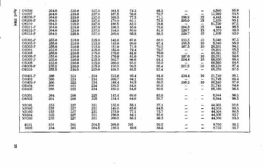
"" ""'" TABLE A.l
RESULTS OF TESTS AT THE UNIVERSITY OF ILLINOIS
0.1% Offset Stress at Initial Initial Initial Prestretch Final ~easurernent ~ark Strength Stress 1% Strain Stress Offset Stress at <s = 1% Stress Time Time Final Stress
f' f. f' f,, f..! f. f.Jf~ Initial Stress
8 • f./f,, ksi ksi ksi ksi % % ksi min. hours %
SOlO I 244.0 150.0 203.0 135.2 90.2 66.7 13,060 92.5 S0102 244.0 150.0 203.0 159.0 106.0 78.3 5,667 90.0 S0103 244.0 150.0 203.0 169.1 112.8 83.3 13,061 89.0 S0104 244.0 150.0 203.0 181.3 120.9 89.3 5,692 88.2 SOlOS 244.0 150.0 203.0 200.0 133.3 98.5 5,692 86.3 S0106 244.0 150.0 203.0 216.0 144.0 106.3 12,946 83.0
SR101 240.0 201.0 210.0 134.2 66.8 63.9 4,680 94.1 SR102 240.0 201.0 210.0 145.3 72.3 69.2 4,060 91.9 SR103 240.0 201.0 210.0 150.8 75.0 71.8 7,095 90.6 SR104 240.0 201.0 210.0 160.0 79.6 76.2 4,874 89.5 SR105 240.0 201.0 210.0 165.7 82.5 78.9 4,824 88.3 SR106 240.0 201.0 210.0 170.1 84.6 81.1 1,775 90.2 SR107 240.0 201.0 210.0 180.4 89.8 85.9 4,660 83.7 SR108 240.0 201.0 210.0 194.0 96.5 92.4 7,155 82.1
OTlOl 214.0 193.5 198.0 133.0 68.8 67.2 41,139 90.3 0Tl02 214.0 193.5 198.0 150.5 77.8 76.0 44,140 87.8 0Tl03 214.0 193.5 198.0 160.0 82.7 80.8 44,140 85.2 0Tl04 214.0 193.5 198.0 171.0 88.4 86.4 44,137 84.7
OR101 250.0 206.0 221.0 146.1 70.9 66.1 1,896 97.5 ORI02 250.0 206.0 221.0 170.0 82.5 76.9 2,015 93.0
"d (j OR201 264.0 218.0 237.0 136.0 62.4 57.4 4,604 97.8 ...... '-< OR202-P 264.0 218.0 237.0 142.7 65.4 60.3 153.7 15 11,948 96.3 0 OR203 264.0 218.0 237.0 151.8 69.6 64.1 11,934 95.9 :::: ... OR204-P 264.0 218.0 237.0 152.8 70.1 64.5 165.2 15 11,903 96.4 ::1 e. OR205-P 264.0 218.0 237.0 161.0 73.9 67.9 176.0 15 1,011 97.5
? OR206 264.0 218.0 237.0 161.8 74.3 68.3 4,560 95.9 g;, OR207 264.0 218.0 237.0 167.5 76.8 70.7 11,980 93.8
OR208-P 264.0 218.0 237.0 168.5 77.3 71.1 186.9 15 4,442 94.4 ..... OR209-P 264.0 218.0 237.0 179.0 82.1 75.5 205.0 15 1,229 95.1 gs ""'"
OR210 264.0 218.0 237.0 186.5 85.5 78.6 81,720 87.2 OR211-P 264.0 218.0 237.0 186.8 85.6 78.8 204.5 15 944 96.5 OR2I2-P 264.0 218.0 237.0 I94.0 89.0 81.9 220.7 15 4,370 92.3 OR2I3-P 264.0 218.0 237.0 209.0 95.8 88.2 229.7 I5 I,205 93.9
OR301-P 255.0 2IO.O 215.0 I42.0 67.6 66.0 I53.5 10 5,040 97.5 OR302-P 255.0 2IO.O 2I5.0 I45.0 69.0 67.4 I58.5 10 5,040 95.9 OR303-P 255.0 2IO.O 2I5.0 I5l.O 71.9 70.2 167.5 10 28,201 94.2 OR304 255.0 210.0 215.0 152.0 72.4 70.7 28,201 95.5 OR305 255.0 210.0 2I5.0 170.0 81.0 79.0 28,32I 92.7 OR306-P 255.0 210.0 2I5.0 I70.0 81.0 79.0 187.0 10 28,32I 92.6 OR307-P 255.0 210.0 2I5.0 202.7 96.6 94.4 224.4 10 68,930 88.4 OR308 255.0 2IO.O 2I5.0 200.0 95.2 93.0 68,560 84.8 OR309-P 255.0 2IO.O 2I5.0 I90.0 90.5 88.4 207.5 10 68,270 87.4 OR3IO 255.0 210.0 2I5.0 I88.0 89.5 87.4 68,270 87.5
OR40I-P 266 223 234 2I2.6 95.4 91.0 234.4 10 21,746 88.I OR402 266 223 234 209.7 94.I 89.6 2I,745 88.4 OR403-P 266 223 234 I88.4 84.5 80.5 205.2 10 68,240 87.0 OR404 266 223 234 I89.0 84.8 80.8 21,743 84.6 OR405 266 223 234 I89.0 84.8 80.8 68,160 86.8
OR501 264 208 225 143.4 69.0 63.8 8,944 96.3 OR502 264 208 225 I34.4 64.6 59.7 8,944 96.5
NRIOI 255 227 23I I32.0 58. I 57.1 44,303 92.6 NR102 255 227 23I 149.0 65.6 64.5 44,303 89.3 NR103 255 227 23I I75.0 77.I 75.7 44,304 86.5 NR104 255 227 231 190.8 84.1 82.6 44,305 83.7 NR105 255 227 23I 200.0 88.I 86.5 44,309 83.3
BIOI 234 20I 204.5 203.0 101 99.2 9,703 89.1 BI02 234 201 204.5 180.1 89.6 88.2 8,735 95.7

at its midpoint. ( 4) An ear-phone, mounted close
to the wire to pick up the forced vibration of the wire.
( 5) A cathode-ray oscilloscope; the output of the oscillator was fed directly into the horizontal deflecting plates, and the .current generated in the ear-phone by · the vibrating wire was fed into the vertical deflecting plates.
When the oscillator frequency coincided with the natural frequency of the wire, a "figure eight" was obtained on the oscilloscope, since the wire made one complete oscillation for both the positive and negative half-cycles of the driving current.
The wire was vibrated in the third mode for two reasons: ( 1) It reduced the effects of uncertainties regarding the end conditions of the wires, and ( 2) it raised the frequency of the wire to a pitch at which it was audible, and hence the resonant frequency could be located approximately by ear. Thus, the resonant position was indicated by three means:
( 1) sound, ( 2) appearance of a "figure eight"
on the oscilloscope, and ( 3) reaching of the maximum
vertical dimension of the figure on the oscilloscope.
The maximum vertical dimension of the figure eight increased greatly at resonance necessitating reduction in the amplification of the oscillator output.
Test Procedures and Results
The frequency of vibration of a stressed string is given by the ex-pression
36
f = !5__ /Tg 2L~ w (A.1)
where f =frequency of lateral vibration
k = 1, 2, 3, . 00
L = length of string T =force
wIg = mass per unit length Equation A.1 was not directly
applicable to the test conditions because the wires had a finite, though small, bending stiffness and the test frames were not absolutely rigid. However, a linear calibration could be obtained between the stress in the wire and the square of the frequency for a particular mode of vibration. Therefore, the stress in thP wires was determined from individual calibrations. The calibration was obtained by making several frequency measurements as the wire was stressed to the desired level for series S0100, SRlOO, OR-100, OR200, and OR300. Since it was felt that this procedure might affect relaxation losses, the calibration was obtained for the remaining series from two calibration tests on identical wire samples prior to the stressing of the actual test specimen in. a particular position in the test frame.
Thus, in some tests the desired level of stress was reached in five increments, with the frequency measured at each increment, while in others the desired stress was reached on one increment. As soon as this stress was reached the wire was anchored and the third-mode f-rpquency was read immediately. This reading was taken to indicate the initial stress level in the wire. The dial gages, if any, were set as soon as the frequency reading was made.
The wire was subsequently vibrated at suitable intervals of time to obtain the stress in the wire and changes in the dial gage readings,
PCI Journal

if any, were noted. Several readings were taken in the first hour of test and later at greater intervals of time, in accordance with the de-
creasing rate of relaxation. The test results for the 57 speci
mens are reported in detail in Fig. A.3, A.4, A.5 and Table A.l.
APPENDIX B TESTS AT VARIOUS LABORATORIES
The following sections contain brief summaries of research on relaxation characteristics of prestressing reinforcement reported in the literature. The data from each investigation are tabulated at the end of this appendix.
Swiss Federal Testing Laboratory-1946
(a) Object and Scope E.M.P.A. Report No. 155, a com
prehensive report on prestressed concrete, included results of relaxation tests on 0.126-in. diameter, colddrawn Swedish wire. Three wires with tensile strength of 279 ksi, were tested at initial stresses of 56, 66 and 76 percent of tensile strength for periods of 11, 16 and 56 days, respectively. (b) Results and Conclusions
At initial stress of 56, 66 and 76 percent of tensile strength, losses were 2.7, 5.0, and 9.3 percent of the initial stress, respectively. It was observed that the relaxation loss increased with increase in initial stress. It was felt that the test periods were sufficiently long to observe the total relaxation loss.
Dawance-1948
(a) Object and Scope The tests conducted by Dawance
were carried out to determine the relaxation characteristics of 0.08-in., 0.1-in. and 0.2-in. diameter colddrawn wires. The initial stress on the 0.1-in. diameter wire ranged from 67 to 113 percent of the 0.2
April 1964
percent proof stress and the initial stress on the 0.2-in. diameter wire was varied between 0.62 and 1.17 of the 0.2 percent proof stress. The duration of test extended from about 6.5 days to over two years.
To measure the stress in the specimens, the vibration technique was developed as part of the research program. ( b ) Results and Conclusions
The maximum losses recorded for the 0.1-in. diameter wire were about 13 percent of initial stress at time of about 2 years. For the same diameter wire, losses of about 10 percent were obsenred at 300 days. The greatest losses obtained for the 0.2-in. diameter wire were 9 percent of initial stress when the initial stress was 111 percent of the 0.2 percent proof stress.
The author noted that for wires whose stress versus logarithm of time plots exhibited a point of contraHexure, it would be possible to establish a limit of relaxation.
Magnel-1948
(a) Object and Scope The purpose of the author's pa
per was to present results of creep tests on concrete and creep and relaxation tests on prestressing wire, and to draw conclusions from these results.
The relaxation losses were measured for a period of over 300 hours on two 82 ft. specimens of 0.2-in. cold-drawn wire. The initial stress of both specimens was 123,000 psi
37

or 85 percent of the 0.1-percent off-set stress.
For one specimen, an overstress of 137,000 psi was held for two minutes and then the stress was reduced to 123,000 psi. The initial stress for the second specimen was applied directly with no overstress. (b) Results and Conclusions
For the specimen not subjected to prestretching, the loss was 12 percent of initial stress at the end of 12 days and was considered to be the complete stress reduction for the wire.
After two days, the loss for the prestretched specimen was 4 percent of the initial stress. The author felt this to be the limiting value of loss for the specimen.
Spare-1952, 1954
(a) Object and Scope The object was to provide users
of high strength wire with information on stability of stress over long periods of time.
The 1952 tests included two specimens of 0.192-in. diameter colddrawn wire at initial stresses of 60 and 70 percent of tensile strength.
The relaxation tests conducted in 1954 consisted of nine cold-drawn and five stress-relieved specimens 0.2-in. in diameter. Initial stress varied from 54 to 93 percent of tensile strength.
For both series of tests, the facilities and procedures were the same. The specimens were 100-ft. long with wire stress measured by the aid of a load cell using the balancing technique (See Chapter 2). The test duration was 1000 hours for all specimens. ( b ) Results and Conclusions
In comparing losses of cold-drawn and stress-relieved wire, the author concluded that, for initial stresses
38
below 60 to 70 percent of tensile strength, stress-relieved wire had losses which are less than those for cold-drawn wire. For initial stresses above approximately 70 percent of tensile strength, cold-drawn wire had losses greater than those for stress-relieved wire.
It was noted that the rate of loss diminished rapidly and the results obtained at 1000 hours should be close to the final value for loss.
Bannister-1953
(a) Object and Scope Tests were made primarily to
study the effect of heat treatment on the relaxation characteristics of cold-drawn wire.
Four types of specimens were tested in the series for a duration of 250 hours. Specimens designated 1 and 2 were in the as-drawn condition, however, specimens 2 were produced by smaller reductions of area in the drawing process. To determine the effect of heat treatment on relaxation losses, two types of stress-relieved wires were tested. The stress-relieved specimens were designated 1-H and 1-H-T where T indicates that the wire was stressrelieved under tension. The wires were tested under initial stresses varying from 69 to 119 percent of the 0.1-percent proof stress to cover the range normally used in prestressed concrete construction.
As part of the test program, the tensile strength of wire 1 was measured after cooling from temperatures ranging from 212oF to 935° F. (b) Results and Conclusions
The heat-treated specimens, 1-H, had lower losses than the as-drawn wires, 1, at the lower initial stresses, but had losses greater than those for wires 1 at the higher initial
PCI Journal

stresses. However, the wires heat treated under tension had lower losses than the as-drawn wire regardless of the initial stress and also had lower losses than the heattreated specimens 1-H throughout the range of initial stress.
From the results of the tensile strength temperature tests a plot was made showing the tensile strength at the various temperatures. In the range 390oF to 750°F, the tensile strength is either unchanged or increased. Outside this range of temperatures the tensile strength was reduced.
In the conclusions of the paper the author states: "The characteristics of drawn wires are not a simple function of either diameter or maximum strength, but are dependent on the basic material and its treatment, and the extent and manner of subsequent cold reduction and aging. The relaxation of such wires is not related to elastic characteristics or the maximum strength or elongation at this stress."
Clark and Walley-1953
(a) Object and Scope The object of this investigation
was to determine the relaxation losses of cold-drawn wires obtained commercially.
The wires obtained were 0.104 in., 0.2 in. and 0.276 in. in diameter and had tensile strengths ranging from 225 ksi to 320 ksi. In testing the wires, a lever apparatus was arranged to accommodate specimens about 40 ft. in length. This length was chosen as an approximation of lengths commonly found in prestressed concrete beams. To determine whether a general relationship existed between relaxation loss and initial stress, the test series covered a wide range of initial
April 1964
stress, 29 to 117 percent of the 0.1-percent offset stress. A total of 23 specimens were tested for a duration of 1000 hours.
(b) Results and Conclusions The authors felt that relaxation
loss in a wire is a function of the initial stress and a property of the wire probably dependent on residual stresses and the crystalline structure. The characteristics of the wire would show up in the shape of the stress-strain curve and in the value of tensile strength and ultimate elongation. It was observed that losses were greater for wires wound on small diameter coils than for wires straightened and wound on large diameter coils. Relaxation loss increased at an increasing rate for initial stress levels greater than 40 percent of the 0.1-percent offset stress.
The authors felt that relaxation losses could be reduced by overstressing, especially in pretensioning operations since a large portion of the loss occurs after tensioning and before release.
Gifford-1953 (a) Object and Scope
Gifford tested 10 specimens of 0.2-in. diameter prestressing wire for a duration of over 400 days. Two specimens were tested at each of five levels of initial stress which ranged from 50 to 90 percent of tensile strength in approximately 10-percent increments. At each level of initial stress, one specimen was prestretched for two minutes to a load five percent of tensile strength above the intended initial stress. The stress was determined by measuring the lateral deflection of the 17.5 ft. specimen. (b) Results and Conclusions
Gifford noted that for initial
39

stresses up to 60 percent of the tensile strength, the loss at 420 days was five percent or less of the initial stress and should reach a limiting value of about seven percent. Since losses caused by creep and shrinkage of concrete in prestressed concrete would reduce the initial stress, the value of five percent stress loss due to relaxation was sufficient allowance in design. For initial stresses greater than 60 percent of tensile strength, a higher allowance must be made.
Based on the test results, the author concluded that the effect of prestretch became significant only for wires with initial stress greater than 60 percent of tensile strength.
deStrycker-1953
(a) Ob;ect and Scope One of the earlier investigators
of relaxation characteristics of prestressing wire was deStrycker who reported some test results as early as 1948 and also in 1951. However, 1953 was the year when his most comprehensive report was published.
Tests were carried out by deStrycker to develop reliable and practical testing methods for the steel industry as well as to investigate the mechanism of the relaxation phenomenon and its relation to creep. Various types of wire were tested at an initial stress of approximately 60 percent of the tensile strength of the wire. (b) Results and Conclusions
The 1953 reference by deStrycker contains the results of 291 relaxation tests in addition to creep tests on prestressing wire. However, the test duration for 241 of these tests was limited to 23 hours. The results of 50 tests with durations of 72 ( 32 tests) and 360 ( 18 tests) hours are
40
listed in Table B.S. For drawn wires under ordinary
ranges of prestress, deStrycker concluded that creep and relaxation could be expressed approximately as functions of the logarithm of time and that short-duration tests limited to a few days or even a few hours could be used to predict long-time relaxation losses. However, for heat-treated or aged wires, it was not possible to predict the maximum relaxation loss on the basis of short-duration tests.
Prestretching was not found to have a significant effect on relaxation losses.
Burnheim-1954
(a) Ob;ect and Scope The results of 1000-hour relaxa
tion tests on nine 51-ft. specimens of 0.2-in. diameter wire and four specimens of 0.28-in. diameter were presented by Burnheim. The specimens, with tensile strengths ranging from 224 to 246 ksi, were subjected to various levels of initial stress varying between 70 and 190 ksi. ( b ) Results and Conclusions
The losses measured at 1000 hours increased with increasing initial stress. At the lowest value of initial stress, 70 ksi, losses were one to four percent of initial stress while for the highest value of initial stress, 190 ksi, loss was nine percent of initial stress.
Schwier-1955
(a) Obiect and Scope The loss of prestress for various
types of steel was investigated by tests on 16 specimens. Four types of specimens were tested: stressrelieved and nonstress-relieved wires and strands. The strand was made up of seven wires each of
PCI Journal

0.118 in. diameter with a tensile strength of either 258, 266 or 278 ksi. For the wires tested, the diameter varied between 0.158 and 0.407 inches and the tensile strength ranged from 238 to 270 ksi. To measure stress in the specimen, a lever arrangement was used. The specimens were tested for 1000 hours at levels of initial stress from about 48 to 92 percent of the tensile strength. (b) Results and Conclusions
The results of the relaxation tests showed that up to an initial stress of about 70 percent of tensile strength nonstress-relieved specimens exhibited greater loss of stress than stress-relieved specimens. From this observation, the author concluded that stress-relieved steel is more favorable for use in prestressing.
C.U.R. [The Dutch Committee for Research]-1958
(a) Object and Scope The tests were carried out to in
vestigate the relaxation characteristics of cold-drawn and hot-rolled wire. A total of 21 specimens were tested for periods ranging from 300 to 3000 hours. Five types of wires were included: ( 1) cold-drawn, ( 2) cold-drawn and straightened, ( 3) cold-drawn and martempered, ( 4) cold-drawn and aged, and ( 5) hot-rolled, hardened and tempered.
The wires had a nominal diameter of 0.20 in. The initial stress varied from 62 to 118 percent of the 0.1 percent offset stress.
The lever system was used to measure the stress. (b) Results and Conclusions
The results are shown in Table B.10. The major conclusion was that a test duration of 3000 hours is in-
April 1964
sufficient to make predictions about the maximum loss expected.
Dumas-1958
(a) Obfect and Scope Results are presented to show the
effect of prestretch on relaxation losses. Twenty-six specimens were tested at levels of initial stress ranging from about 60 to 90 percent of the tensile strength. No information was given on the type of wire and size of specimens. At each level of initial stress, one specimen was not overstressed; other specimens were prestretched for two minutes at various amounts of overstress. The duration of tests varied from 500 to 1500 hours. (b) Results and Conclusions
It is concluded that prestretching is an effective technique to reduce relaxation loss. As overstress was increased for a particular level of initial stress, measured losses were reduced. It must be noted, however, that even for prestretched specimens, losses were substantial. This was particularly true for specimens tested at high initial stress. At 1000 hours, specimens with no overstress and an initial stress of 85 to 88 percent of tensile strength had losses amounting to 13 percent of initial stress while for specimens at the same level of initial stress and subjected to prestretching at the initial stress for two minutes, loss was measured to be from 14 to 15 percent of the initial stress.
Kajfasz-1958
(a) Object and Scope A series of relaxation tests were
conducted on 0.1-in. cold-drawn wire. The specimens tested were of two types: single wire and twintwisted strand in which the pitch of twist was varied from 0.9 in. to
41

infinity. Forty-six specimens of each type were tested for durations which varied from 10 to 130 days (Results are reported for only 80 tests). Initial stresses applied to the single strand specimens ranged from 77 to 108 percent of the 0.2-percent offset stress. Twelve of the single strand specimens were overstressed 10 percent above the initial stress for 10 minutes. All specimens were 79 in. long and were mounted in steel frames of rolled sections. To maintain constant length during the test period, a lever system was arranged such that weights were removed from an arm as wire stress decreased. From the statics of the system, wire stress was determined. (b) Results and Conclusions
The author compared results obtained for the series of tests conducted with other published results. He concluded that the basis of comparison of relaxation tests should be the ratio of initial stress to the 0.2-percent offset stress.
The results of Kajfasis tests on the single wire strand and results reported by Levi were used to study the relation between rate of relaxation and time; The following formula was developed to describe relaxation 1~:
fr = c(log t - log to) where fr =relaxation in kg/mm2
c = a parameter depending on the ratio of initial stress to the 0.2-percent offset stress
logt =natural logarithm of time in minutes . ·
log t0 ==natural logarithm of time in minutes at which first reading was taken.
The parameter c was evaluated by assuming it was a linear function of the ratio of initial stress to offset stress. By including in the expression
42.
the loss occurring from zero time to the time at which the first reading was taken, the total loss at time, t, can be determined.
From extrapolation of the test results, Kajfasz noted that for an initial stress less than 0.55 of the 0.2-percent offset stress, losses are not of practical significance.
The parameter, c, was also evaluated for the twin-twisted strands. For values of initial stress less than the 0.2-percent offset stress, the value of c was nearly the same as that for single wire strand.
In evaluating the effect of prestretching on companion specimens at the same level of initial stress, Kajfasz noted that only in the verv early stages of the test was there a noticeable difference in losses between the prestretched and nonprestretched specimens. During the following period of testing, the losses were nearly identical for the companion specimens.
Levi-1958
(a) Object and Scope At the Second and Third Con
gresses of the Federation Internationale de la Prccontrainte, Levi presented results of an extensive series of tests on prestressing steel.
The diameter of the wires tested varied from 0.078 to 0.31 in. with tensile strengths of 182 ksi to 313 ksi. The initial stress applied to the specimens ranged from 52 to 90 percent of tensile strength.
Specimens were tested for durations of 120 hours to nearly nine years. From results of tests of long duration, it was felt that losses a~ 120 hours would indicate final values cif loss, therefore, a considerable number of tests were terminated at that time.
PCI Journal
( b ) Results and Conclusions Based on results of wires tested
for long periods of time, the author concluded that the relaxation at 120 hours would be little more than half the final value. By carrying tests out to 120 hours, it would be possible to estimate the final value of relaxation loss.
In considering the results with respect to initial stress, the author stated that a stress of about 80 percent of the 0.2-percent proof stress can be maintained indefinitely.
Papsdorf and Schwier-1958
(a) Object and Scope The authors studied the creep
and relaxation of prestressing steel by conducting a survey of research literature and carrying out relaxation tests. The purpose was to examine behavior in an effort to arrive at a means ofobtaining the loss of stress over a long period of time.
In the relaxation tests carried out, specimens were tested for 1000 hours at temperatures ranging from 72oF to 302°F. The specimens were made from a drawn and tempered wire 0.26 in. in diameter with a tensile strength of 254 ksi and the 0.2 percent proof stress of 224 ksi. To measure the loss of stress in the wire, a lever system was used which had a distance between anchorages of either 67 inches or 79 inches. The initial stress ranged from 43 to 96 percent of the tensile strength. (b) Results and Conclusions
From their own tests and from others, the authors concluded that the strain versus logarithm of time curves in constant-stress tests and stress versus logarithm of time curves in relaxation tests exhibited a point of inflection which occurred after a length of time depending on the magnitude of the initial
April 1964
stress applied. The results of relaxation tests at
various temperatures showed that elevated temperatures produced higher relaxation losses at 1000 hours for initial stresses on the order of 55 to 60 percent of the tensile strength. With longer test periods the influence of temperature was noticed to be less. An increase in the initial stress had a similar effect in that the influence of temperature diminished for increasing loads.
The authors believe that tests at elevated temperatures will enable the relaxation curves to be determined fairly accurately without having to resort to excessively long test durations.
Jevtic-1959
(a) Object and Scope Relaxation tests and tests of ten
sile strength at elevated temperatures were conducted by Jevtic as part of a program to determine the properties of cold-drawn wire manufactured in Jesenice, Yugoslavia.
The relaxation tests consisted of measuring losses on two series of specimens. One series of 0.1-in. diameter wire contained five specimens with f • .!fv ranging from 0.91 to 1.19. In the second series, three wires of 0.2-in. diameter were subjected to f.,;/fv from 0.90 to 1.12. The test duration was 696 hours for the 0.1-in. diameter specimens. In the second series, the period of test was 720 hours for two specimens and 796 hours for the third specimen. Since the vibration method- was used to measure wire stress, each specimen was mounted in a suitable steel frame. All wires tested had a free length of 80.7 in. (b) Results and Conclusions
At the end of the test duration,
43

specimens of the first test series had losses ranging from 8.2 percent to 3.3 percent of the initial stress where the greater losses occurred in the wires with the higher initial stress. For the specimens of 0.2-in. diameter, losses at the final time ranged from 7.9 percent to 4.7 percent of the initial stress.
Kin~ham, Fisher and Viest-1961
(a) Obfect and Scope As part of the bridge research
at the AASHO Road Test, a study of the long-time behavior of prestressed concrete beams was carried out. In conjunction with the study, relaxation tests were conducted on stress-relieved prestressing steel used in the construction of bridge beams in the Road Tests.
The relaxation tests consisted of determining losses in two types of specimens: 0.192-in. diameter wire and seven-wire strand of 0.375-in. diameter with a mean cross-sectional area of 0.0806 square inches. Eight wire specimens and 10 specimens of seven-wire strand were tested for a minimum duration of 1000 hours with two specimens of each type observed for more than 7000 hours. To measure stress in the wires, the vibration technique was employed. For the seven-wire strand, a load cell was used to measure stress. Each specimen was mounted in a steel frame where the distance between anchorages was approximately 40 in. [nitial stress
44
for the specimens ranged from 60 to 78 percent of tensile strength. ( b ) Results and Conclusions
From the results of the relaxation tests, the authors noted that substantial losses occurred beyond 1000 hours and although the rate of loss decreased with time, there was no indication that losses would approach a limiting value. At 1000 hours, losses for the wire specimens ranged from 4.2 to 9.0 percent of the initial stress while losses for the seven-wire strand varied between 2.0 and 6.1 percent of the initial stress.
In the analysis of test data, the authors developed a formula to be used in estimating relaxation losses in prestressed concrete beams. Using a modified form of similar formulas found in literature, the final expression was written as follows:
[r ]0
ar = f; t; (l- e-tta )b
where ar = relaxation loss at time t fi = initial stress f: = tensile strength e = base of natural logarithm t =time from application of
initial stress in hours a, b, c = empirical constants
Test data from 10 to 1000 hours was used to evaluate the empirical constants by multiple regression analyses. The authors concluded that the duration of their tests was not sufficient to provide information on the limiting value of the relaxation loss.
PCI Journal

TABLE B.1 E.M.P.A. 1946
Offset Initial Initial Mark" Diameter Strength Stress'"' Stress Offset
t: t. f,, I ,.If. in. ksi ksi ksi %
1 0.126 279 240 156 65 2 0.126 279 240 185 77 3 0.126 279 240 213 89
Length of Specimen: Not reported. Type of Steel: Cold-Drawn single wire from Sweden. Method of Stress Measurement: Not reported. " Not indicated in original report. "" Based on 0.2 percent strain.
TABLE B.2 DAWANCE 1948
Offset Initial Initial Mark" Diameter Strength Stress"" Stress Offset
f' ' t. t,, I ,.If. in. ksi ks; ksi %
1 0.10 284 226 152 67 2 0.10 284 226 152 67 3 0.10 284 226 152 69 4 0.10 284 226 156 69 5 0.20 224 183 114 62
6 0.20 224 183 114 62 7 0.20 224 183 152 83 8 0.20 224 183 152 83 9 0.20 224 183 204 111
10 0.20 224 183 204 111
11 0.20 224 183 182 99 12 0.20 224 183 182 99 13 0.20 224 183 214 117 14 0.20 224 183 214 117 15 0.10 284 226 256 113
16 0.10 284 226 256 113 17 0.10 284 226 204 90 18 0.10 284 226 204 90
Length of Specimen: 19.7 to 78.8 in. Type of Steel: Cold-drawn single wire. Method of Stress Measurement: Vibration. " Not indicated in original report. "" Based on 0.2 percent strain.
TABLE B.3 MAGNEL
Offset Initial Mark Diameter Strength Stress" Stress
f' fu f,. in. ksi ksi ksi
3 0.'20 216 145 123 4 0.20 216 145 123
Length of Specimen: 82 ft. Type of Steel: Cold-drawn single wire. Method of Stress Measurement: Balancing. " Based on 0.1 percent stress.
April 1964
1948
Initial Offset f,;f y
%
85 85
Prestretch Final Measurement Stress Time Time Final Stress
Initial Stress 1,/f,,
ksi min. hours %
288 97.3 388 95.0
1344 90.7
Prestretch Final Measurement Stress Time T,me Final Stress
Initial Stress f./f,,
ksi min. hours %
7200 91 7200 90 9350 88 9350 87
156 96
156 95 228 97 228 97 156 91 156 91
408 94 408 93 288 92 288 92
19200 87
19200 87 19200 90 19200 91
Prestretch Final Measurement Stress Time T:me Final Stress
Initial Stress 1,/t,,
ksi min. hours %
300 88 137 2 300 96.4
---~.
45

TABLE B.4 SPARE 1952 and 1954
Prestretch Final Measurement Offset Initial Initial Stress Time Time Final Stress
Mark~ Diameter Strength Stress Stress Offset Initial Stress f' fy f,, t,Jfy Ut,, .
in. ksi ksi ksi % ksi min. hours %
1 0.20 223 145 1000 93 2 0.20 223 167 1000 93 3 0.20 253 222 1000 90 4 0.20 253 235 1000 88 5 0.20 260 141 1000 96
6 0.20 260 174 1000 93 7 0.20 260 208 1000 91 8 0.20 249 154 1000 95 9 0.20 249 172 1000 92
10 0.20 270 189 1000 93
11 0.20 249 179 1000 92 12 0.20 249 194 1000 87 13 0.20 240 168 1000 92 14 0.20 272 155 1000 97 15 0.192 250 155 1000 94
16 0.192 250 172 1000 92
Length of Specimen: 100 ft. Type of Steel: Cold-Drawn (Specimens 11 through 15 were stress-relieved). Method of Stress Measurement: Balancing. ~Not indicated in original report.
TABLE B.5 BANNISTER 1953
Prestretch Final Measurement Offset Initial Initial Stress Time Time Final Stress
Mark Diameter Strength Stress~ Stress Offset Initial Stress f'. t. f,, f,jfy Ut .•
in. ksi ksi ksi % ksi min. hours %
1 0.20 226 150 134 89 250 96 1 0.20 226 150 157 105 250 96 1 0.20 226 150 179 119 250 94
2 0.20 241 195 134 69 250 97 2 0.20 241 195 157 80 250 96 2 0.20 241 195 179 92 250 95
1-H 0.20 235 150 134 89 250 97 1-H 0.20 235 150 157 105 250 95 1-H 0.20 235 150 179 119 250 92
1-H-Tu 0.20 236 201 157 78 8 99 1-H-Tu 0.20 236 201 179 89 8 99
Length of Specimen: 3 ft. Type of Steel: Cold-drawn single wire (Specimens 1-H were heat-treated and specimens
1-H-T were heat-treated under tension). Method of Stress Measurement: Lever. ~ Based on 0.1 percent strain. u Not included in over-all tally because of limited test duration.
46 PCI Journal

TABLE B.6 CLARK AND WALLEY 1953
Prestretch Final Measurement Offset Initial Initial Stress Time Time Final Stress
Mark Diameter Strength Stress" Stress Offset Initial Stress f. t. f., f.Jt. f,/f,,
in. ksi ksi ksi % ksi min. hours %
1 0.104 260 177 52 29 1000 94 2 0.104 256 179 105 59 1000 92 3 0.104 260 177 157 89 1000 93 4 0.104 256 179 210 117 1000 90 5 0.104 308 224 70 31 1000 97
6 0.104 316 211 146 70 1000 95 7 0.104 311 211 175 83 1000 95 8 0.104 320 244 204 84 1000 94 9 0.104 320 244 232 95 1000 94
10 0.104 308 225 255 114 1000 90
11 0.20 225 125 70 44 1000 96 12 0.20 251 168 120 71 1000 95 13 0.20 248 161 130 81 1000 95 14 0.20 238 161 142 88 1000 92 15 0.20 238 161 152 95 1000 92
16 0.20 190 97 1000 92 17 0.20 251 212 70 33 1000 92 18 0.20 251 212 130 61 1000 98 19 0.20 251 212 170 80 1000 98 20 0.276 229 187 67 37 1000 95
21 0.276 229 187 101 55 1000 99 22 0.276 229 187 130 69 1000 98 23 0.276 225 187 168 90 1000 96
Length of Specimen: 40 ft. Type of Steel: Cold-Drawn single wire. Method of Stress Measurement: Lever. " Based on 0.1 percent strain.
TABLE B.7 GIFFORD 1953
Prestretch Final Measurement Offset Initial Initial Stress Time Time Final Stress
Mark Diameter Strength Stress" Stress Offset Initial Stress f. f y f,, f,Jt. fJfd
in. ksi ksi ksi % ksi min. hours %
1 0.20 241 210 207 98 219 2 10080 84 20 0.20 241 210 203 97 10080 84
2 0.20 241 210 182 87 194 2 10080 91 19 0.20 241 210 182 87 10080 89
3 0.20 241 210 164 78 176 2 10080 94 18 0.20 241 210 157 75 10080 93
4 0.20 241 210 129 61 141 2 10080 97 17 0.20 241 210 129 61 10080 97
5 0.20 241 210 104 50 116 2 10080 96 16 0.20 241 210 104 50 10080 97
Length of Specimen: 17 ft. 6 in. Type of Steel: Single wire. Method of Stress Measurement: Deflection. " Based on 0.1 percent strain.
April 1964 47

TABLE 8.8 deSTRYCKER 1953
Prestretch Final Measurement Offset Initial Initial Stress Time Time Final Stress
Mark Diameter Strength Stress Stress Offset Initial Stress f' t. f,, f,.Jt. f,!f, ' in. ksi ksi ksi % ksi min. hours %
B313 " 121 72 95.7 B516 - " 121 72 95.4 B712 " 121 72 95.8
SA03 0.274 223 123 360 95.7 SA13 0.274 223 123 72 96.5 SF03 0.274 229 124 360 95.7 SF13 0.274 229 124 360 96.2 SF23 0.274 229 124 72 96.8
SB03 0.238 239 121 72 96.7 SB13 0.238 239 121 360 95.8 SB23 0.238 239 121 72 96.7
SG04 0.236 236 121 360 96.2 SG14 0.236 236 121 72 97.0 SG24 0.236 236 121 360 97.0 SC06 0.198 236 120 72 95.9 SC16 0.198 236 120 360 95.1 SC23 0.198 236 120 72 96.0 SH03 0.198 236 121 72 97.3 SH13 0.198 236 121 360 96.3 SH23 0.198 236 121 72 97.1
SD05 0.157 245 119 72 95.7 SD13 0.157 245 119 72 95.7 SD23 0.157 245 119 360 94.7 SD34 0.157 245 119 72 96.1 SD43 0.157 245 119 72 95.8
SI03 0.157 256 124 360 95.6 Sll3 0.157 256 124 72 96.6 SI23 0.157 256 124 72 96.7
PA02 0.277 222 135 360 97.7 PA12 0.277 222 135 72 98.2 PA22 0.277 222 135 72 98.2 PB02 0.199 252 150 72 98.4 PB12 0.199 252 150 72 99.1
PC02 0.159 234 141 360 97.2 PC12 0.159 234 141 72 98.3 PC22 0.159 234 141 72 98.3
PF04 0.198 239 152 360 98.5 PF14 0.198 239 152 360 98.4 PF23 0.198 239 152 72 99.0 PF33 0.198 239 152 72 98.9
PG03 0.278 220 136 360 97.6 PG14 0.278 220 136 72 98.0 PG23 0.278 220 136 72 98.2 PG33 0.278 220 136 72 98.3
BB03 0.276 228 136 360 97.8 BB14 0.276 228 136 360 97.1 BB23 0.276 228 136 72 98.5
48 PCI Journal

[ BC03
I' BC13 BC23
0.198 0.198 0.198
242 242 242
TABLE B.8 (Cont.)
146 146 146
72 360
72
96.7 96.0 97.5
Length of Specimen: 10 to 22 in. Type of Steel: Cold drawn single wire. Wires of Series P were aged. Wires of Series SA
were straightened. Method of Stress Measurement: Lever. "Probably 0.2 in.
TABLE B.9 BURNHEIM 1954
Prestretch Final Measurement Offset Initial Initial Stress Time Time Final Stress
Mark" Diameter Strength"" Stress Stress Offset Initial Stress t: f. f,, f,.lf. f,/f,, in. ksi ksi ksi % ksi min. hours %
1 0.20 190 1000 91 2 0.20 150 1000 92 3 0.20 140 1000 92 4 0.20 130 1000 95 5 0.20 120 1000 95
6 0.20 70 1000 96 7 0.28 168 1000 96 8 0.28 130 1000 98 9 0.28 100 1000 99
10 0.28 67 1000 99
11 0.20 170 1000 95 12 0.20 130 1000 98 13 0.20 70 1000 98
Length of Specimen: 51 ft. Type of Steel: Single wire. Method of Stress Measurement: Lever. " Not indicated in original report. "" reported to range from 224 to 246 ksi.
TABLE 8.10 SCHWIER 1955
Prestretch "Final Measurement Offset In Tal Initial Stress Time Time Final Stress
Mark" Diameter Strength Stress"" S>ress Offset Initial Stress f' f. f,, f,,Jt. Ut,, ' in. ksi ksi ksi % ksi min. hours %
1a 0.158 270 210 149 71 1000 94.3 2a 0.158 270 210 176 84 1000 92.3 3a 0.158 270 210 203 96 1000 91.3 4a 0.158 270 210 229 108 1000 90.2 5a 0.158 270 210 248 118 1000 89.0
6b 0.407 246 229 123 54 1000 99.2 7h 0.389 238 214 135 64 1000 99.0 8b 0.368 249 228 149 66 1000 98.7
9c 7 X 0.118 266 192 133 70 1000 93.2 10c 7 X 0.118 258 192 156 R2 1000 91.0 11c 7 X 0.118 258 192 181 95 1000 89.0
12rl 7 X 0.118 278 260 132 51 1000 98 R 13d 7 X 0.118 278 260 162 62 1000 97.7
April 1964 49

r-
TABLE B.lO (Cont.) 14d 7 X 0.118 278 260 181 69 1000 96.2 15d 7 X 0.118 278 260 222 85 1000 91.5 16d 7 X 0.118 278 260 235 91 1000 88.2
Length of Specimen: 39.4 in. Type of Steel: a-Cold-drawn wire; b-Stress-Relieved wire; c-Nonstress-Relieved 7 X
0.118" strand; d-Stress-Relieved 7 X 0.118" strand. Method of Stress Measurement: Lever. " Not indicated in original report. "" Based on 0.2 percent strain.
TABLE B.11 C.U.R. 1958
Prestretch Final Measurement Offset Initial Initial Stress Time Time Final Stress
Mark Diameter Strength Stress" Stress Offset Initial Stress f. f. f,, f,.lf. f,/f,,
in.40 ksi ksi ksi o/o ksi min. hours o/o
B-a 0.20 235 157 128 82 128 1 300 95 B-b 0.20 235 157 142 90 142 1 500 95 B-e 0.20 235 157 157 100 157 1 2000 92 B-d 0.20 235 157 171 109 171 1 300 94
C-a 0.20 232 145 128 88 128 1 300 95 C-b 0.20 232 145 142 98 142 1 300 94 C-c 0.20 232 145 158 109 158 1 3000 91 C-d 0.20 232 145 171 ll8 171 1 300 92
D-a 0.20 242 219 135 62 135 1 300 97 D-b 0.20 242 219 142 65 142 1 500 97 D-e 0.20 242 219 150 69 150 1 300 97 D-d 0.20 242 219 166 76 166 1 3000 92
F-a 0.20 228 208 128 62 128 1 300 99 F-b 0.20 228 208 142 68 142 1 500 97 F-e 0.20 228 208 159 76 159 1 3000 92 F-d 0.20 228 208 179 86 179 1 500 88
H-a 0.20" 226 212 142 67 142 1 300 99 H-e 0.20" 226 212 150 71 150 1 3000 98 H-b 0.20" 226 212 157 74 157 1 500 98 H-e 0.20" 226 212 166 78 166 1 300 96 H-d 0.20" 226 212 188 89 188 1 3000 89
Length of Specimen: (Not given in report). Type of Steel: B-cold-drawn; C-cold-drawn, straightened; D-cold-drawn. aged; F-
cold-drawn, martempered; H-hot-rolled, hardened, tempered. Method of Stress Measurement: Lever. " Based on 0.1 percent strain. ""Specimens with diameter marked with superscript a have an elliptical cross section.
TABLE B.12 DUMAS 1958
Prestretch Final Measurement Offset Initial Initial Stress Time Time Final Stress
Mark Diameter Strength Stress Stress Offset Initial Stress I' f '" I ..If. f,/f,, . v
in. ksi ksi ksi % ksi min. hours %
lAd 242 142 142 2 500 93 2Ad 242 142 156 2 500 95 3Car 242 142 171 2 700 96 4Ad 242 142 192 2 1000 96 lAb 242 142 213 2 1000 96 No.2 242 142 206 2 1500 96 No. 3BG 242 142 1000 93
50 PCI Journal

TABLE 8.12 (Cont.)
2Ba 242 156 171 2 1000 95 3Ba 242 156 156 2 500 92 4Ba 242 156 192 2 1000 96 2Bb 242 156 213 2 1000 95 No.5 242 156 206 2 1000 96 4DAR 242 156 1000 91
3Ca 242 171 171 2 1000 91 4Ca 242 171 191 2 1000 93 3Cb 242 171 213 2 1000 94 No.9 242 171 206 2 1000 93 2Ab 242 171 1000 88
4Da 242 192 192 2 1000 89 4Ab 242 192 213 2 1000 92 No.8 242 192 206 2 1000 90 No.1 242 192 1000 86
No.8 242 206 206 2 1000 87 4Bl 242 206 1000 86
4Db 242 213 213 2 1000 87 4Cb 242 213 1000 85
Length of Specimen: (Not given in report). Type of Steel: Cold-drawn single wire. Method of Stress Measurement: Lever.
TABLE B. 13a KAJFASZ 1958
Prestretch Final Measurement Offset Initial Initial Stress Time Time Final Stress
Mark Diameter Strength Stress" Stress Offset Initial Stress t: f. f,, f,Jt. f,/f.,
in. ksi ksi ksi % ksi min. hours %
3 0.10 320 278 214 77 360 98 3 0.10 320 278 214 77 360 98
13 0.10 320 278 214 77 960 97 13 0.10 320 278 214 77 960 97 22 0.10 320 278 214 77 3600 94 22 0.10 320 278 214 77 3600 96
4 0.10 320 278 214 77 235 10 360 98 4 0.10 320 278 214 77 235 10 360 98
14 0.10 320 278 214 77 235 10 120 99 14 0.10 320 278 214 77 235 10 120 99
5 0.10 320 278 242 87 120 97 5 0.10 320 278 242 87 120 97
23 0.10 320 278 242 87 2880 91 23 0.10 320 278 242 87 2880 92
6 0.10 320 278 242 87 266 10 720 98 6 0.10 320 278 242 87 266 10 720 98
15 0.10 320 278 242 87 266 10 120 99 15 0.10 320 278 242 87 266 10 120 98
9 0.10 320 278 242 87 2880 95
7 0.0985 320 278 270 97 960 95 7 0.0985 320 278 270 97 960 94
18 0.0985 320 278 270 97 96 97 18 0.0985 320 278 270 97 96 97 20 0.0985 320 278 270 97 72 95 20 0.0985 320 278 270 97 72 94
April 1964 51

TABLE B.l3a (Cont.)
8 0.0985 320 278 270 97 297 10 1440 96 8 0.0985 320 278 270 97 297 10 1440 96
16 0.0985 320 278 270 97 297 10 120 98 16 0.0985 320 278 270 97 297 10 120 98
9 0.0985 320 278 270 97 2880 93 19 0.0985 320 278 284 102 480 94 19 0.0985 320 278 299 108 480 95 21 0.0985 320 278 299 108 72 90 21 0.0985 320 278 299 108 72 91
Length of Specimen: 78.7 in. Type of Steel: Cold-Drawn single wire. Method of Stress Measurement: Lever. "' Based on 0.2 percent strain.
TABLE B. 13b KAJFASZ 1958
Prestretch Final Measurement Offset Initial Initial Stress Time Time Final Stress
Mark Diameter Strength Stress"' Stress Offset Initial Stress t: f. f,, fjf. f.lf,.
in. ksi ksi ksi % ksi min. hours %
1 0.10 316 292 214 73 96 97 1 0.10 316 292 214 73 96 97 9 0.10 316 292 214 73 96 98 9 0.10 316 292 214 73 120 98
10 0.10 316 292 214 73 120 95 10 0.10 316 292 214 73 120 96 18 0.10 316 292 214 73 120 97 18 0.10 316 292 214 73 120 98 19 0.10 316 292 214 73 120 97 19 0.10 316 292 214 73 120 97
8 0.10 299 263 214 81 120 96 8 0.10 299 263 214 81 120 96
17 0.10 299 263 214 81 96 96 17 0.10 299 263 214 81 96 96 26 0.10 299 263 214 81 120 96 26 0.10 299 263 214 81 120 95
7 0.10 299 246 214 87 120 96 7 0.10 299 246 214 87 120 96
16 0.10 299 246 214 87 120 96 16 0.10 299 246 214 87 120 95 25 0.10 299 246 214 87 120 94 25 0.10 299 246 214 87 120 93
6 0.10 299 232 214 92 120 94 6 0.10 299 232 214 92 120 94
15 0.10 299 232 214 92 120 93 15 0.10 299 232 214 92 120 93 24 0.10 299 232 214 92 120 94 24 0.10 299 232 214 92 120 94
4 0.10 290 206 214 104 120 92 4 0.10 290 206 214 104 120 93
13 0.10 290 206 214 104 120 92 13 0.10 290 206 214 104 120 93 22 0.10 290 206 214 104 120 92 22 0.10 290 206 214 104 120 93
3 0.10 279 178 214 120 96 90 3 0.10 279 178 214 120 96 88
52 PCI Journal

TABLE B.l3b (Cont.) I
12 0.10 279 178 214 120 96 90 I 12 0.10 279 178 214 120 96 90
21 0.10 279 178 214 120 120 90 21 0.10 279 178 214 120 120 91
2 0.10 264 163 214 131 96 90 2 0.10 264 163 214 131 96 85
11 0.10 264 163 214 131 96 89 11 0.10 264 163 214 131 96 86 20 0.10 264 163 214 131 120 88 20 0.10 264 163 214 131 120 88
Length of Specimen: 78.7 in. Type of Steel: Cold-Drawn two-wire strand (The pitch of the strand varied as follows.
It was 0.9 in. for 2, 11, 20; 1.3 in. for 3, 12, 21; 1.7 in. for 4, 13, 22; 2.5 in. for 6, 15, 24; 3 in. for 7, 16, 25; 3.5 in. for 8, 17, 26, and infinite for 1, 9, 10, 18, 19).
Method of Stress Measurement: Lever. " Based on 0.2 percent strain.
TABLE B. 14 LEVI 1958
Prestretch Final Measurement Offset Initial Initial Stress Time Time Final Stress
Mark Diameter Strength Stress" Stress Offset Initial Stress f. f, f,, f • .lt. Ut,,
in. ksi ksi ksi % ksi min. hours %
1 0.078 302 228 165 72 75000 88 2 0.078 302 228 165 72 74800 88 3 0.078 313 284 228 80 72000 82 4 0.078 288 221 164 74 73600 84 5 0.078 288 221 170 77 73600 83
6 0.20 209 174 154 88 63100 86 7 0.20 213 171 172 100 17700 89 8 0.20 210 168 161 96 52800 91 9 0.20 270 242 178 74 53000 90
10 0.20 239 188 171 91 2130 89 11 0.20 239 188 156 83 5150 89 12 0.20 239 188 171 91 14200 88
13' 0.20 215 173 171 99 47300 90 14' 0.20 182 129 95 74 4150 97 15' 0.20 182 137 87 64 3940 96 16' 0.20 256 249 171 69 40500 91
17 0.08 258 199 39100 87 17bis 0.08 264 204 185 91 120 94
18 0.09 254 201 185 92 120 94 18bis 0.09 268 215 185 86 480 92 18bis 0.09 264 190 185 97 120 93
19 0.20 249 242 185 77 39100 92 20' 0.20 215 173 171 99 6310 89 21 0.20 261 241 185 77 36800 92 22' 0.20 204 194 171 88 36800 93 23" 0.20 204 194 171 88 4220 95 24 0.20 242 214 171 80 120 91 25' 0.20 227 208 171 82 4240 95 26• 0.20 230 230 171 74 120 97 27 0.20 242 234 171 73 4360 90
28 0.15 282 267 171 64 4240 96 April 1964 53

TABLE B.l4 (Cont.)
29 0.20 224 210 171 82 120 96 30• 0.20 212 212 171 81 3260 94 31 0.20 212 211 156 74 32600 94 32 0.20 212 212 135 64 32600 96 33 0.20 230 216 168 78 120 97 33 0.20 230 220 171 78 120 97
34 0.31 205 187 171 91 120 95 34 0.31 208 192 171 89 120 95
35 0.28 209 172 163 95 120 95
36 0.16 293 226 171 76 120 96 36 0.16 289 222 171 77 120 96
37 0.20 269 196 171 87 120 94 37 0.20 274 202 171 85 120 94 38 0.20 243 224 171 76 120 95 39 0.20 241 199 171 86 120 95 40 0.20 245 237 171 72 120 98
41 0.20 262 228 135 59 1270 95 42 0.20 262 228 157 69 1300 97 43 0.20 262 228 171 75 1300 94 44 0.20 278 255 157 62 120 97 45 0.20 246 183 171 93 120 91
45 0.20 246 179 17i 95 120 91 45 0.20 244 178 171 96 120 91 45 0.20 251 179 171 95 120 90 45 0.20 251 185 171 92 120 90 46 0.20 262 228 171 75 120 94 46 0.20 262 228 171 75 120 95
47 0.20 251 240 171 71 120 98 47 0.20 253 241 171 71 120 98 47bis 0.20 251 240 181 75 120 97 47bis 0.20 253 241 223 97 120 91
53 0.28 221 193 199 103 120 94 53 0.28 221 193 185 96 120 95 53 0.28 221 193 171 89 120 96 53 0.28 221 193 157 81 120 96
54 0.20 232 212 171 81 120 99 55 0.28 235 204 171 84 120
56 0.20 240 196b 171 87 120 95 56 0.20 240 198b 171 87 120 95 58 0.20 250 202b 171 85 120 92 58 0.20 254 202b 142 70 120 94 58 0.20 254 202b 150 74 120 93 58 0.20 249 189b 171 90 120 90
59 0.28 222 193b 171 89 120 92 59 0.28 222 188b 157 84 120 92 59 0.28 222 193b 171 89 120 91 59 0.28 222 192b 157 82 120 92
61 0.20 255 186 149 80 120 93 61 0.20 274 196 171 87 120 91 61 0.20 268 190 171 90 120 92 61bis 0.20 259 189 149 79 120 94 62 0.20 251 168 178 106 120 91
62 0.20 257 168 178 106 120 90
54 PCI Journal

TABLE B.14 (Cont.) 65 0.20 215 194 171 88 120 94 65 0.20 215 192 171 89 120 95 66 0.20 253 166 171 103 120 90 66 0.20 254 163 171 105 120 90
67 0.20 267 246 171 70 840 97 68 0.20 241 197 171 87 120 94 68 0.20 241 202 171 84 120 94 69 0.20 245 180 171 95 120 95 69 0.20 245 176 171 97 120 95
72 0.20 272 228b 171 75 >.,.- 120 96 72 0.20 271 228b 171 75 120 96 73 0.20 242 228b 135 59 120 98 73 0.20 242 228b 135 59 120 98 73 0.20 242 228b 135 59 120 98
74 0.20 242 228b 171 75 19300 91 75 0.20 242 228b 135 59 19300 97
Length of Specimen: 9 ft. 10 in. Type of Steel: Cold-Drawn single wire. Some specimens, marked by the superscript a in
the table, were cut from rolled wire. Method of Stress Measurement: Lever. "Based on 0.1 percent strain. Some values marked by the superscript b in the table, were
based on 0.2 percent strain. TABLE B. 15
PAPSDORF AND SCHWIER 1958
Prestretch Final Measurement Offset Initial Initial Stress Time Time Final
M~rk" Diameter Strength Stress"" Stress Offset Stress""" Initial Stress
f. f. f,, f.Jf. Uf, in. ksi ksi ksi % ksi min. hours %
1a 0.26 254 223 109 49 1000 99 1b 0.26 254 223 109 49 1000 98 1c 0.26 254 223 109 49 1000 97 1d 0.26 254 223 109 49 1000 92 1e 0.26 254 223 109 49 1000 90
2a 0.26 254 223 132 59 1000 99 2b 0.26 254 223 132 59 1000 97 2c 0.26 254 223 132 59 1000 95 2d 0.26 254 223 132 59 1000 91 2e 0.26 254 223 132 59 1000 91
3a 0.26 254 223 157 70 1000 96 3b 0.26 254 223 157 70 1000 93 3c 0.26 254 223 157 70 1000 90 3d 0.26 254 223 157 70 1000 88 3e 0.26 254 223 157 70 1000 87
4a 0.26 254 223 180 81 1000 92 4b 0.26 254 223 180 81 1000 88 4c 0.26 254 223 180 81 1000 85 4d 0.26 254 223 180 81 1000 83
5a 0.26 254 223 206 92 1000 86 5b 0.26 254 223 206 92 1000 82 5c 0.26 254 223 206 92 1000 79 5d 0.26 > 254 223 206 92 1000 78
6a 0.26 254 223 228 102 1000 81 6b 0.26 254 223 228 102 1000 79 6r 0.26 254 223 228 102 1000 78
April Hi64 55

TABLE B.15 (Cont.) 6d 0.26 254 223 228 102 1000 77
7a 0.26 254 223 244 109 1000 80 7b 0.26 254 223 244 109 1000 79 7c 0.26 254 223 244 109 1000 78 7d 0.26 254 223 244 109 1000 78
Length of Specimen: a, b, c-67 or 79 inches; d and e-79 inches. Type of Steel: Drawn and Tempered. Method of Stress Measurement: Lever. " Not indicated in original report. "" Based on 0.2% proof stress. """The final stress represents an average obtained from 2 to 5 test specimens. a-Test Temperature 72oF; b-Test Temperature 95°F; c-Test Temperature 122°F; d-Test Temperature 212°F; e-Test Temperature 302°F.
Mark"
1 2 3 4 5
6 7 8
TABLE B. 16 JEVTIC 1959
Offset Initial Diameter Strength Stress"" Stress
Initial Offset
'; f. f,, in. ksi ksi ksi
f.Jf. %
0.1 0.1 0.1 0.1 0.1'
0.2 0.2 0.2
271 271 271 271 271
214 214 214
189 189 189 189 189
156 156 156
173 91.5 176 93.1 189 100.0 202 107 226 119
141 90.4 155 99.4 174 112.4
Prestretch Stress Time
ksi min.
Final Measurement Time Final Stress
Initial Stress f,/f,,
hours %
696 696 696 696 696
720 720 792
96.7 95.3 95.2 94.5 91.8
95.3 94.4 92.1
--------------------------------------------------------- ·--
Length of Specimen: 80.7 in. Type of Steel: Cold-drawn single wire. Method of Stress Measurement: Vibration. " Not indicated in original paper. " Based on 0.1 percent strain.
TABLE B. 17 ------------· VIEST, KINGHAM, AND FISHEILlJ~-=-1 _______ ,
Mark
509 507 506 505 502 504 503 510
604 609 610 607 602
56
Diameter Strength f.
in. ksi
0.192 0.192 0.192 0.192 0.192 0.192 0.192 0.192
0.375 0.375 0.375 0.375 0.375
257 257 257 257 257 257 257 257
265 265 265 265 265
Offset Initial Stress Stress f. f., ksi ksi
215 215 215 215 215 215 215 215
240 240 240 240 240
199.1 196.4 187.5 184.7 180.8 180.5 175.0 169.1
187.5 185.0 165.4 163.0 158.0
Initial Offset f,,lf.
%
92.6 91.3 87.2 85.9 84.1 84.0 81.4 78.7
78.1 77.1 69.0 68.0 65.9
Prestretch Stress Time
Final Measurement Time Final Stress
Initial Stress f.lf,,
ksi min. hours %
219.1 216.4 207.5 204.7 200.8 200.5 195.0 189.1
a a a a a
1 1 1 1 1 1 1 1
1000 1000 1000 1000 1000 1000 1000 1000
0.3-0.5 1000 0.3-0.5 1000 0.3-0.5 1000 0.3-0.5 1000 0.3-0.5 1000
91.0 92.8 92.1 94.1 92.9 95.7 95.8 95.1
94.6 93.6 97.0 97.4 98.0
PCI Journal

TABLE B.l7 (Cont.)
606 0.375 275 240 195.5 81.5 a 0.3-0.5 1000 93.9 608 0.375 275 240 189.0 78.8 a 0.3-0.5 1000 95.7 603 0.375 275 240 185.8 77.5 a 0.3-0.5 1000 96.1 601 0.375 275 240 169.3 70.6 a 0.3-0.5 1000 96.9 605 0.375 275 240 168.3 70.1 a 0.3-0.5 1000 96.5
Length of Specimen: About 3 ft. 4 in. Type of Steel: Cold-Drawn stress relieved wire in Series 500 and cold-drawn stress
relieved seven wire strand in Series 600. Method of Stress Measurement: Vibration for the wires. The stress in the strand was
measured directly. a-An additional stress of 19 to 24 ksi.
April 1964 57