Embed Size (px)
Citation preview

School of Mechanical, Industrial, & Manufacturing
Engineering
Process Analysis and Modeling Using IDEF0
2
School of Mechanical, Industrial, & Manufacturing
Engineering
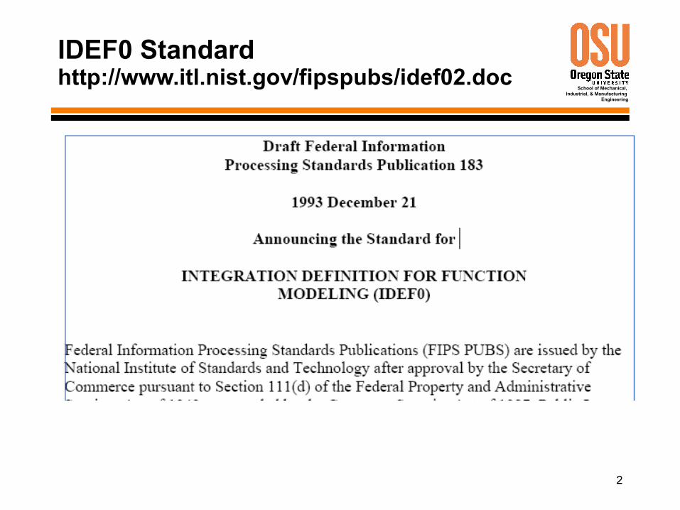
IDEF0 Standardhttp://www.itl.nist.gov/fipspubs/idef02.doc
3
School of Mechanical, Industrial, & Manufacturing
Engineering
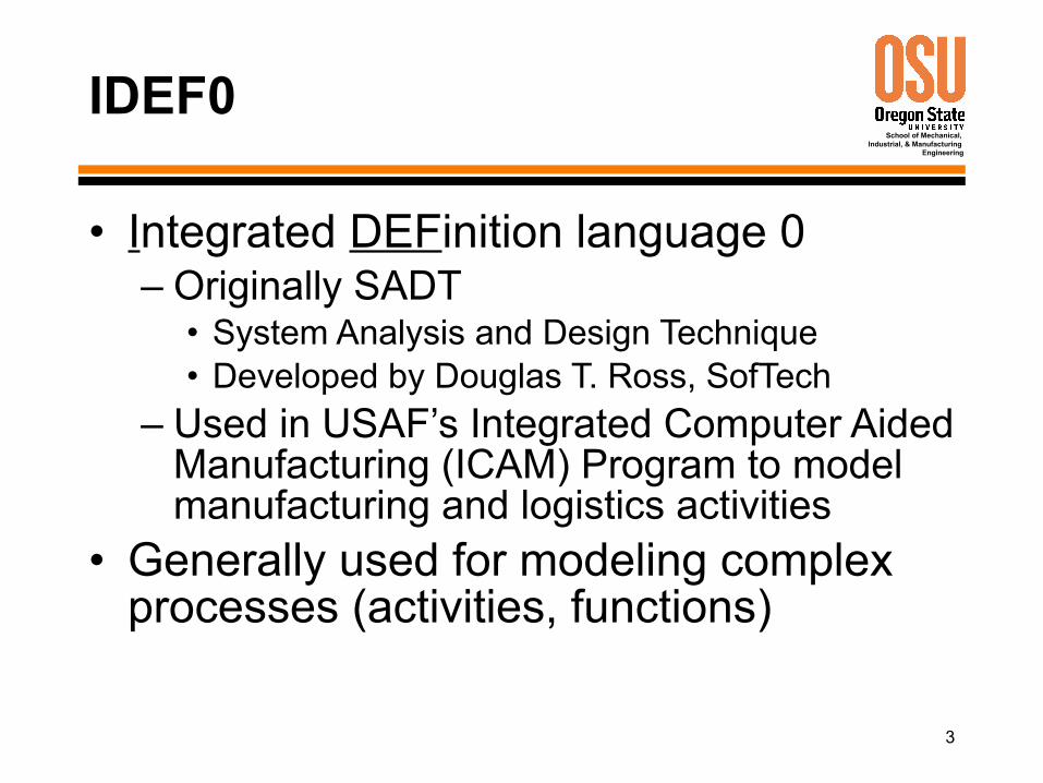
IDEF0
• Integrated DEFinition language 0– Originally SADT
• System Analysis and Design Technique• Developed by Douglas T. Ross, SofTech
– Used in USAF’s Integrated Computer Aided Manufacturing (ICAM) Program to model manufacturing and logistics activities
• Generally used for modeling complex processes (activities, functions)
4
School of Mechanical, Industrial, & Manufacturing
Engineering
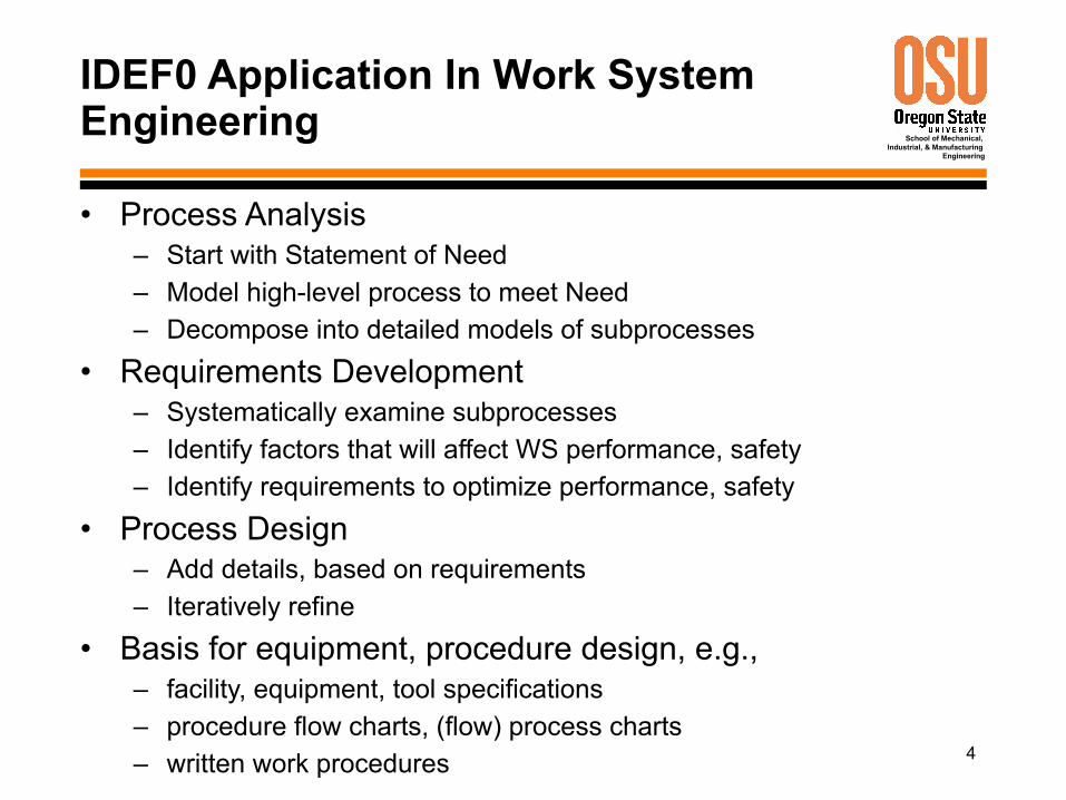
IDEF0 Application In Work System Engineering
• Process Analysis– Start with Statement of Need– Model high-level process to meet Need– Decompose into detailed models of subprocesses
• Requirements Development– Systematically examine subprocesses– Identify factors that will affect WS performance, safety– Identify requirements to optimize performance, safety
• Process Design– Add details, based on requirements
– Iteratively refine
• Basis for equipment, procedure design, e.g.,– facility, equipment, tool specifications– procedure flow charts, (flow) process charts– written work procedures
5
School of Mechanical, Industrial, & Manufacturing
Engineering
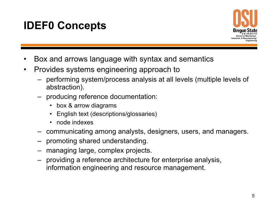
IDEF0 Concepts
• Box and arrows language with syntax and semantics• Provides systems engineering approach to
– performing system/process analysis at all levels (multiple levels of abstraction).
– producing reference documentation:• box & arrow diagrams• English text (descriptions/glossaries)• node indexes
– communicating among analysts, designers, users, and managers.– promoting shared understanding.– managing large, complex projects.– providing a reference architecture for enterprise analysis,
information engineering and resource management.
6
School of Mechanical, Industrial, & Manufacturing
Engineering
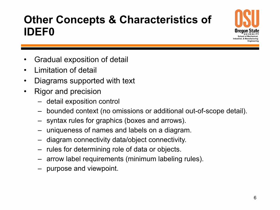
Other Concepts & Characteristics of IDEF0
• Gradual exposition of detail• Limitation of detail• Diagrams supported with text• Rigor and precision
– detail exposition control– bounded context (no omissions or additional out-of-scope detail).– syntax rules for graphics (boxes and arrows).– uniqueness of names and labels on a diagram.– diagram connectivity data/object connectivity.– rules for determining role of data or objects.– arrow label requirements (minimum labeling rules).– purpose and viewpoint.
7
School of Mechanical, Industrial, & Manufacturing
Engineering
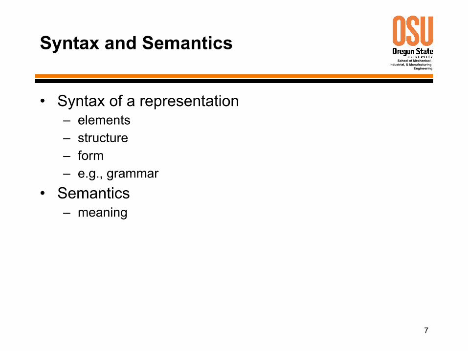
Syntax and Semantics
• Syntax of a representation– elements– structure– form– e.g., grammar
• Semantics– meaning
8
School of Mechanical, Industrial, & Manufacturing
Engineering
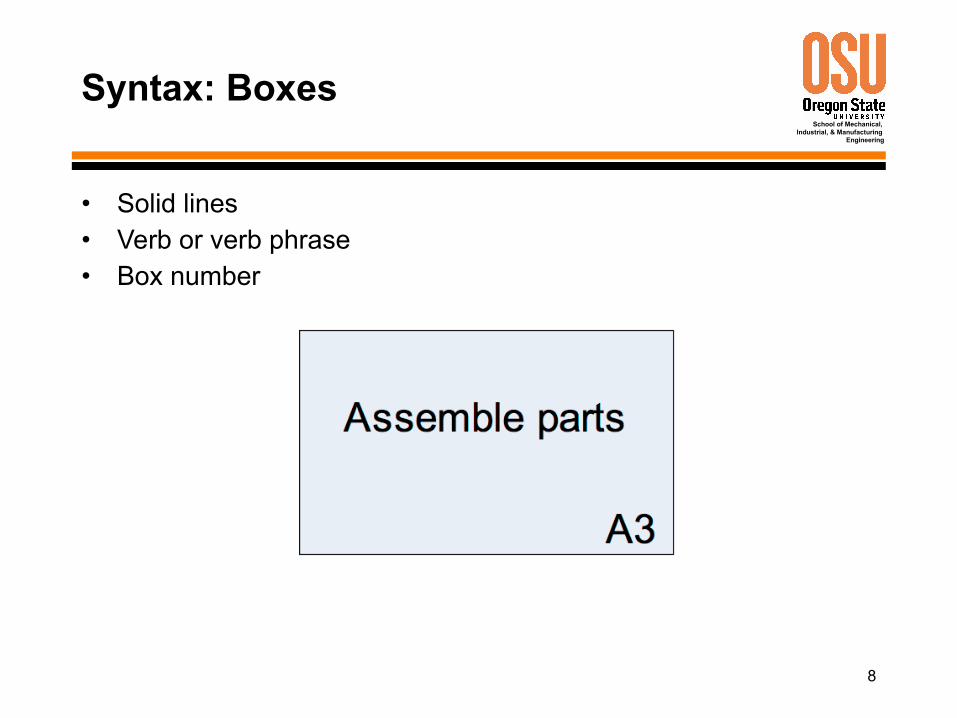
Syntax: Boxes
• Solid lines• Verb or verb phrase• Box number
9
School of Mechanical, Industrial, & Manufacturing
Engineering
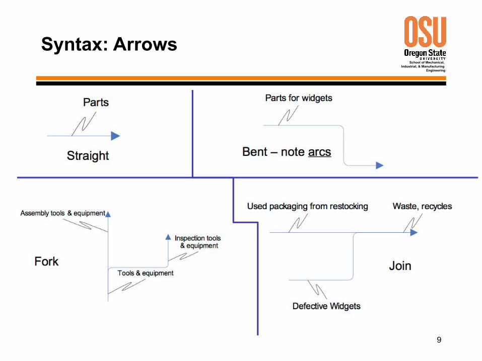
Syntax: Arrows
10
School of Mechanical, Industrial, & Manufacturing
Engineering
Box and Arrow Syntax Rules
• Boxes– Boxes shall be sufficient in size to insert box name.– Boxes shall be rectangular in shape, with square corners.– Boxes shall be drawn with solid lines.
• Arrows– Arrows that bend shall be curved using only 90 degree arcs.– Arrows shall be drawn in solid line segments.– Arrows shall be drawn vertically or horizontally, not
diagonally.– Arrow ends shall touch the outer perimeter of the function
box and shall not cross into the box.– Arrows shall attach at box sides, not at corners.
11
School of Mechanical, Industrial, & Manufacturing
Engineering
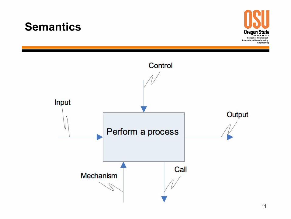
Semantics
12
School of Mechanical, Industrial, & Manufacturing
Engineering
Semantics
Something (matter, energy, information, system) transformed by the process
Something that guides, facilitates, limits, or
constrains the process
Something that results
from the process
A means by which the process is
performed
A reference to another model.
13
School of Mechanical, Industrial, & Manufacturing
Engineering
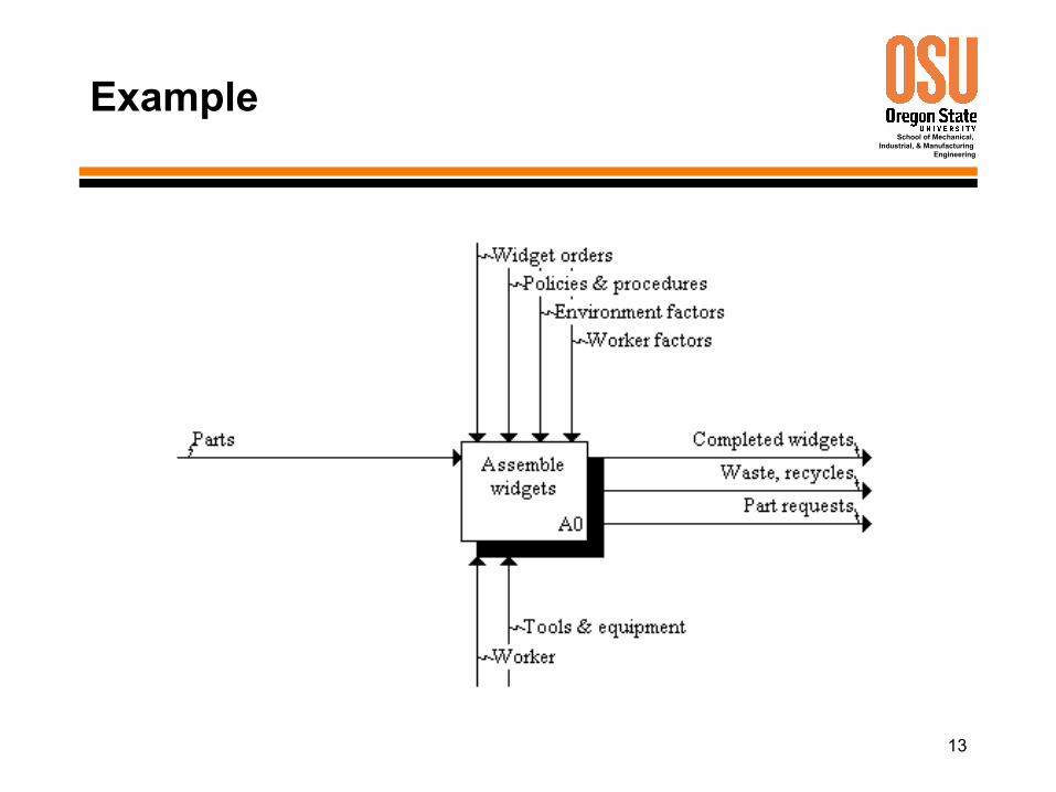
Example
14
School of Mechanical, Industrial, & Manufacturing
Engineering
More Box and Arrow Syntax Rules
• A box shall be named with an active verb or verb phrase.• Each side of a function box shall have a standard box/arrow
relationship:a. Input arrows shall interface with the left side of a box.b. Control arrows shall interface with the top side of a box.c. Output arrows shall interface with the right side of the box.d. Mechanism arrows (except call arrows) shall point upward and shall
connect to the bottom side of the box.e. Mechanism call arrows shall point downward, shall connect to the
bottom side of the box, and shall be labeled with the reference expression for the box which details the subject box.
• Arrow segments, except for call arrows, shall be labeled with a noun or noun phrase unless a single arrow label clearly applies to the arrow as a whole.
• A “squiggle” ( ) shall be used to link an arrow with its associated label, unless the arrow/label relationship is obvious.
• Arrow labels shall not consist solely of any of the following terms: function, input, control, output, mechanism, or call.
15
School of Mechanical, Industrial, & Manufacturing
Engineering
IDEF0 Diagrams and Text
• Top-Level Context Diagram• Child Diagram• Parent Diagram• Text and Glossary• For Exposition Only Diagrams
16
School of Mechanical, Industrial, & Manufacturing
Engineering
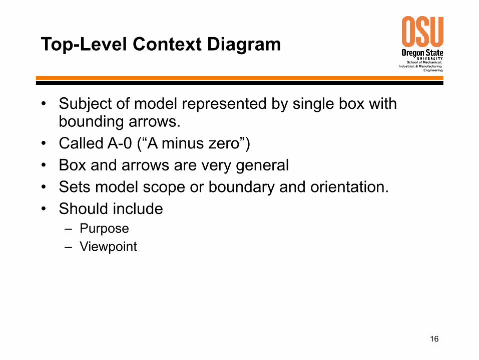
Top-Level Context Diagram
• Subject of model represented by single box with bounding arrows.
• Called A-0 (“A minus zero”)• Box and arrows are very general• Sets model scope or boundary and orientation.• Should include
– Purpose– Viewpoint
17
School of Mechanical, Industrial, & Manufacturing
Engineering
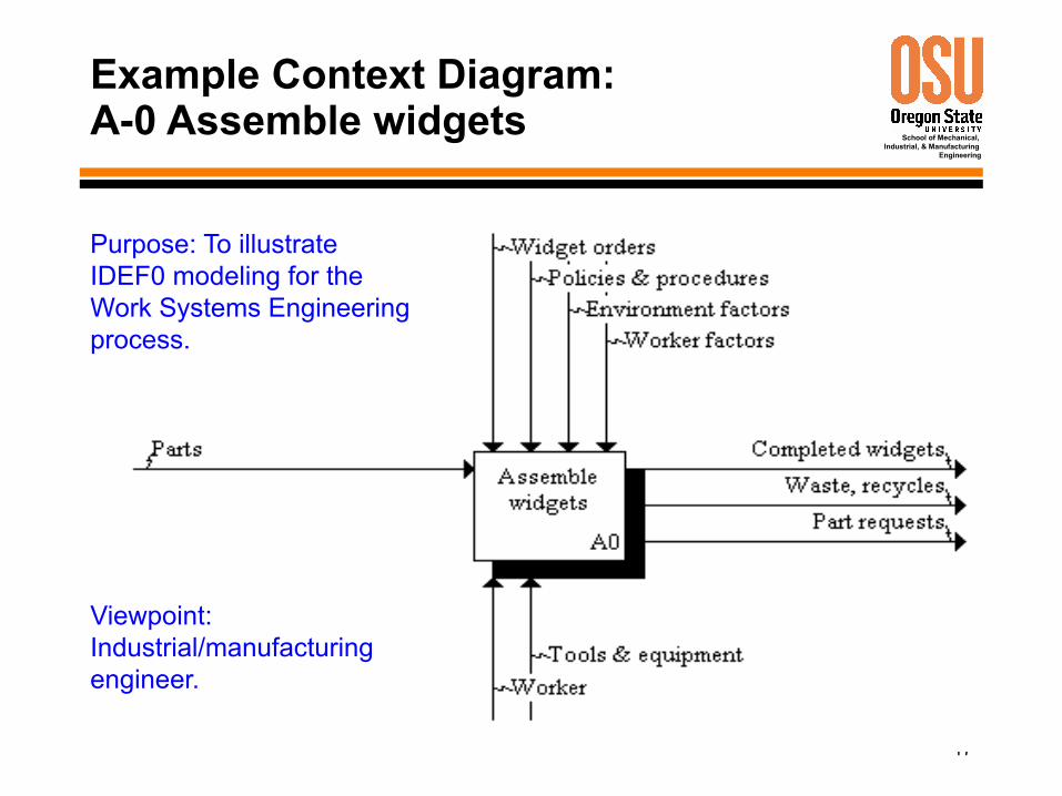
Example Context Diagram:A-0 Assemble widgets
Purpose: To illustrate IDEF0 modeling for the Work Systems Engineering process.
Viewpoint: Industrial/manufacturing engineer.
18
School of Mechanical, Industrial, & Manufacturing
Engineering
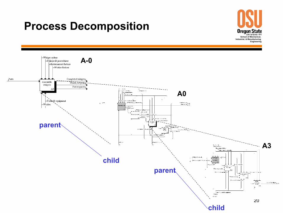
Child Diagram
• Single process in Context Diagram (A-0) may be decomposed into subprocesses and modeled in a child (A0) diagram.
• Each process in the A0 diagram may be decomposed further into subprocesses and modeled in (grand-) child (A1, A2, … A6) diagrams.
• Each (grand-) child process may be decomposed further into subprocesses and modeling (great-grand-) child diagrams.
• And so on …
19
School of Mechanical, Industrial, & Manufacturing
Engineering
Parent Diagram
• Diagram that contains one or more parent boxes, i.e., boxes detailed on child diagrams.
20
School of Mechanical, Industrial, & Manufacturing
Engineering
Process Decomposition
A-0
A0
A3
parent
childparent
child
21
School of Mechanical, Industrial, & Manufacturing
Engineering
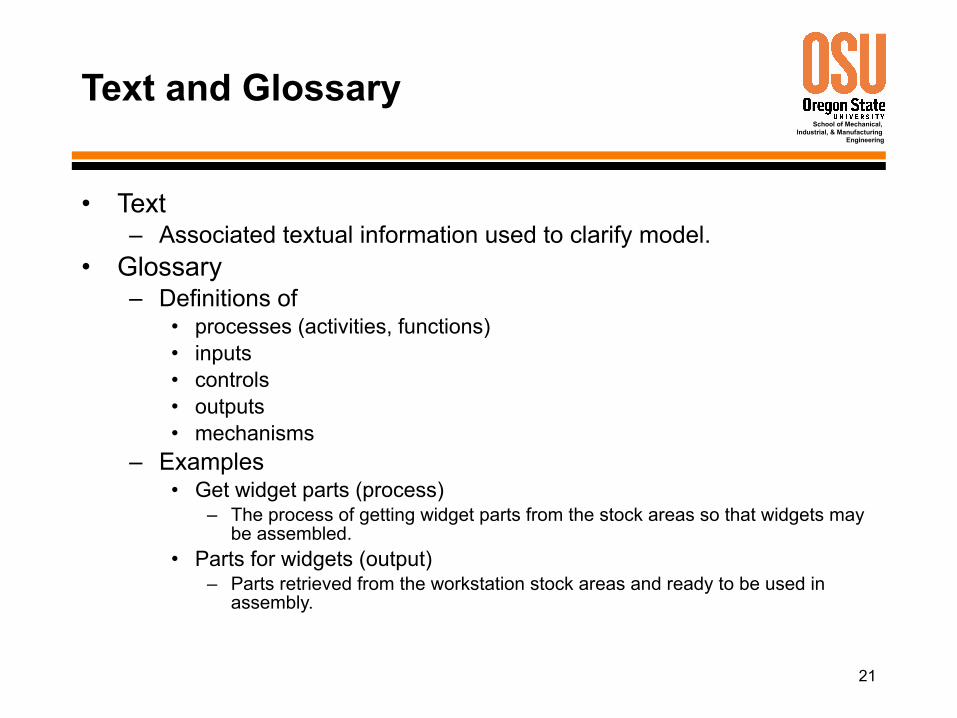
Text and Glossary
• Text– Associated textual information used to clarify model.
• Glossary– Definitions of
• processes (activities, functions)• inputs• controls• outputs• mechanisms
– Examples• Get widget parts (process)
– The process of getting widget parts from the stock areas so that widgets may be assembled.
• Parts for widgets (output)– Parts retrieved from the workstation stock areas and ready to be used in
assembly.
22
School of Mechanical, Industrial, & Manufacturing
Engineering
For Exposition Only Diagram
• FEO (“fee-oh”)• Provides supplementary information to help reader
understand model.• Need not comply with IDEF0 rules• Example: Flowchart to describe a procedure
(action/decision sequence) that can be used to perform the process.
23
School of Mechanical, Industrial, & Manufacturing
Engineering
Diagram Features
• Arrows As Constraints• Concurrent Operation• Arrows As Pipelines• Branching Arrows• Inter-Box Connections• Boundary Arrows• Tunneled Arrows• Call Arrows
24
School of Mechanical, Industrial, & Manufacturing
Engineering
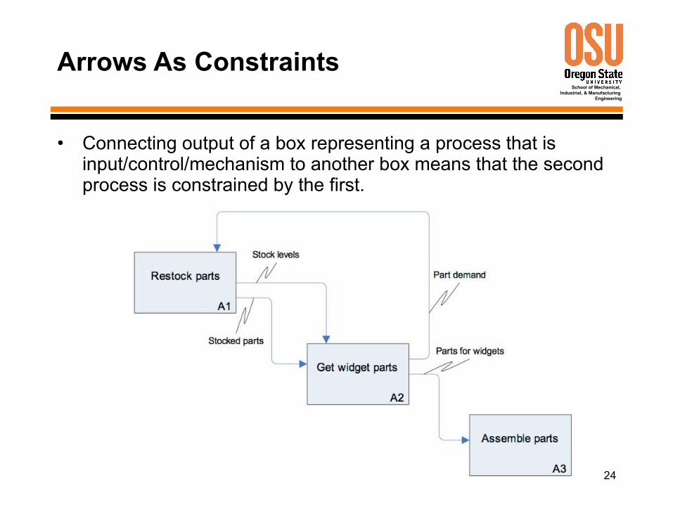
Arrows As Constraints
• Connecting output of a box representing a process that is input/control/mechanism to another box means that the second process is constrained by the first.
25
School of Mechanical, Industrial, & Manufacturing
Engineering
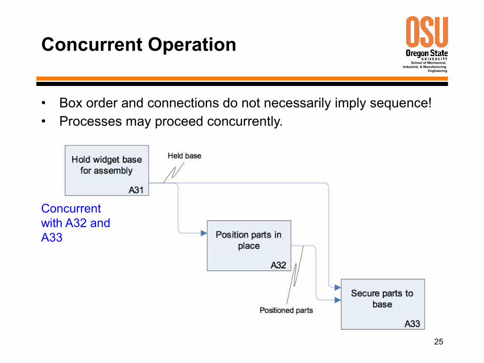
Concurrent Operation
• Box order and connections do not necessarily imply sequence!• Processes may proceed concurrently.
Concurrent with A32 and A33
26
School of Mechanical, Industrial, & Manufacturing
Engineering
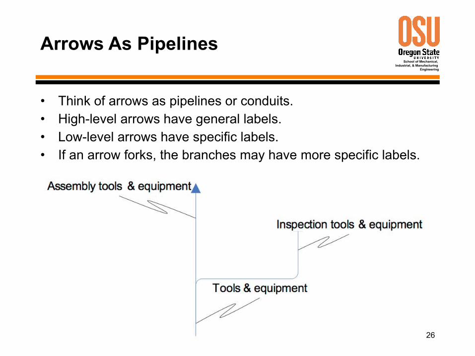
Arrows As Pipelines
• Think of arrows as pipelines or conduits.• High-level arrows have general labels.• Low-level arrows have specific labels.• If an arrow forks, the branches may have more specific labels.
27
School of Mechanical, Industrial, & Manufacturing
Engineering
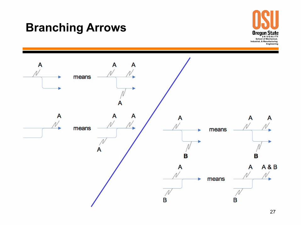
Branching Arrows
28
School of Mechanical, Industrial, & Manufacturing
Engineering
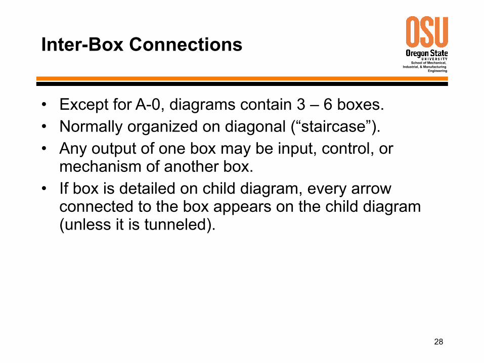
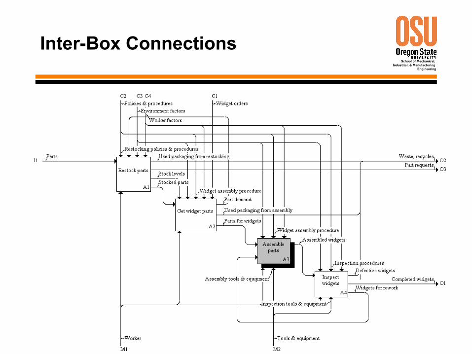
Inter-Box Connections
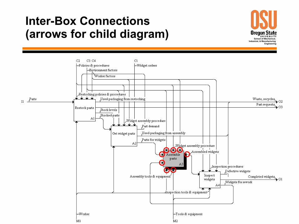
• Except for A-0, diagrams contain 3 – 6 boxes.• Normally organized on diagonal (“staircase”).• Any output of one box may be input, control, or
mechanism of another box.• If box is detailed on child diagram, every arrow
connected to the box appears on the child diagram (unless it is tunneled).
29
School of Mechanical, Industrial, & Manufacturing
Engineering
Inter-Box Connections
30
School of Mechanical, Industrial, & Manufacturing
Engineering
Inter-Box Connections(arrows for child diagram)
31
School of Mechanical, Industrial, & Manufacturing
Engineering
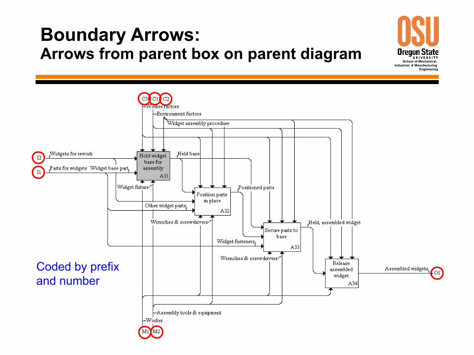
Boundary Arrows:Arrows from parent box on parent diagram
Coded by prefix and number

32
School of Mechanical, Industrial, & Manufacturing
Engineering
to be continued …
33
School of Mechanical, Industrial, & Manufacturing
Engineering
WSE Project Assignment
1. IDEF0 A-0 diagram (hand-drawn OK)2. IDEF0 A0 diagram (hand-drawn OK)3. IDEF0 glossary (typed)4. Requirements Version 15. Progress Report 1
i. Cover: Memo Evaluation Form (provided by instructor)ii. Memo (see syllabus)iii. Separator page: Work Products Evaluation Form (provided by
instructor)iv. Copies of work products (see above)