Embed Size (px)
Citation preview
Process Optimization of Bismaleimide (BMI) Resin Infused Carbon Fiber Composite
Joshua W. Ehrlich, LaNetra C. Tate, Sarah B. Cox, Brian J. Taylor, M. Clara Wright, Anne J. Caraccio, Jeffery W. Sampson
National Aeronautics and Space Administration NASA
Kennedy Space Center, FL 32899
ABSTRACT Bismaleimide (BMI) resins are an attractive new addition to world-wide composite
applications. This type of thermosetting polyimide provides several unique characteristics such as excellent physical property retention at elevated temperatures and in wet environments, constant electrical properties over a vast array of temperature settings, and nonflammability properties as well. This makes BMI a popular choice in advance composites and electronics applications [IJ. Bismaleimide-2 (BMI-2) resin was used to infuse intermediate modulus 7 (IM7) based carbon fiber. Two panel configurations consisting of 4 plies with [ +45°, 90°)2 and [0°]4
orientations were fabricated. For tensile testing, a [90°]4 configuration was tested by rotating the [0°]4 configirration to lie orthogonal with the load direction of the test fixture.
Curing of the BMI-2/IM7 system utilized an optimal infusion process which focused on the integration of the manufacturer-recommended ramp rates,. hold times, and cure temperatures. Completion of the cure cycle for the BMI-2/IM7 composite yielded a product with multiple surface voids determined through visual and metallographic observation. Although the curing cycle was the same for the three panellayups, the surface voids that remained within the material post-cure were different in abundance, shape, and size. For tensile testing, the [0°]4 layup had a 19.9% and 21.7% greater average tensile strain performance compared to the [90°]4 and [+45°, 90°, 90°,-45°] layups, respectively, at failure. For tensile stress performance, the [0°]4 layup had a 5.8% and 34.0% greater average performance% than the [90°]4 and [+45°, 90°, 90°,-45°] layups.
1. INTRODUCTION
1.1 General
Engineers today are presented with the challenge to design and build the next generation of space hardware out of the lightest, strongest, and most durable materials available. Composites offer excellent structural characteristics and outstanding reliability in many forms. The NASA funded Composites for Exploration (CoEx) project investigated dry composite structures and materials technologies with direct application to enable NASA's future space exploration needs. This effort evaluated the use of graphite/BMI Out of Autoclave (OoA) material processes for use in repair patch-work systems. BMI-matrix composite systems have higher operating temperature capability than epoxy-matrix systems [2J, which is believed to make for an ideal design incorporation ideal for payload fairing structures where the dominant design conditions call for thermal loadings.
Development and testing on these systems and resin/fiber systems will provide useful data and opportunities to define parameters for engineering an optimal composite matrix tailored to a variety of applications. One such application involving the OoA systems is their usage on primary structures. Composite-bonded repairs have been shown to be more cost effective than mechanically fastened repairs or full replacement of the damaged structure [3J. Although bonded repair has been a common and widely used method [4l, new material systems and material/resin combination must be properly optimized to determine appropriate cure profile, produce uniform bondlines, and minimize residual stress effects on the repair patch, adhesive, and repaired system as a structural unit. With bonded repair, the damaged area is removed and replaced with a new patch. Among the common repair patch fabrication methods available, resin infusion within the substrate provides several benefits that make this method particularly suitable for high load structural applications, which involves designing a system comprised of a high modulus yield for added stiffness while minimizing mass accumulation from the optimized resin infusion process to prevent an increase in loads and costs.
2. EXPERUWENTATION
2.1 Composite Components
The Carbon fiber fabric, consisting of a 5-hamess satin IM7-GP-6K configuration incorporating a Kevlar® 195 gram denier leno fiber construction with a fabric areal weight of 193 g/m"2 was purchased from Textile Products Incorporated.
The BMI-2 resin system, a catalyzed version of the BMI-1 formulation based on similar handling and viscosity characteristics, was purchased from Raptor Resins, LLC [SJ. Its reactivity temperature approaches 230°F (110°C), making it more reactive but significantly possessing less flow capability than BMI -1 which allows for molten infusion to occur at lower temperatures than other infusion resins [6l. Additionally, BMI resins are capable of these high temperatures uses, compared to epoxies, while still possessing the same epoxy-like processing many aerospace industry epoxy users are widely familiar with. Epoxies have earned wide acceptance in the industry because of its excellent mechanical properties, ease of manufacturing, and service temperature range. However, many applications require service temperature ranges higher than the capabilities of epoxies, which fall in the range of BMI resin [IJ.
2.2 Panel Layup Configuration
The fabric was sectioned into 12 in. square sections to produce samples with areas equivalent to the caull plate placed on top of the fiber pack used with the vacuum bagging system. To prevent individual yarns from sliding out of the material, the edges of the cut fabric were taped with ~ in. masking tape. Three panel configurations were fabricated: [0°]4, [90°]4,
[ +45°/90°/90°/-45°].
2.3 Composite Bagging
In order for the resin to be infused into the substrate, the IM7 composite material, BMI-2 resin and experimental area were prepared using the powder infusion bagging process, following the manufacturer recommended procedures. The bagging methodology was provided by the resin manufacturer. The bagging scheme, known as powder infusion, was carried out in the process order shown below; the three separate composite layups were fabricated all in the same manner.
Room-temperature vulcanizing (RTV) silicone was applied to the perimeter of the test specimen, aluminum compression caull plate and fiber pack (including all peel ply & flow media in-between). Edges were smoothed for adequate RTV distribution around the perimeter to create a seal which would form during the curing cycle. The amount ofRTV silicone applied to the edges varied, dependent on whether all voids and bubbles were removed or were not visually present to prevent a seal from forming. The test specimen was left to sit for 24 hours for the RTV silicone seal to form thoroughly. The assembly is shown in Figure 1.
Figure 1- At the top of the image is a piece of the porous Teflon® material used to allow additional infusion of the resin through the composite due to suction (not shown is half of the porous Teflon underneath the fiber pack, which
provided additional suction power on the resin from the vacuum pump).
The amount of matrix content required for complete infusion of the fiber pack was determined with Equation 2, in which Wm is the matrix content percentage by weight, Ar is the weight/unit area of one sheet of reinforcement, N is the number of sheets in the test specimen, Pc the specimen density (see Equation 1), Mi the total mass of the specimen, A the total specimen area, and h the specimen thickness [?J.
(1)
W. = lOO _ (Ar X N X 0.1) m PcXh
(2)
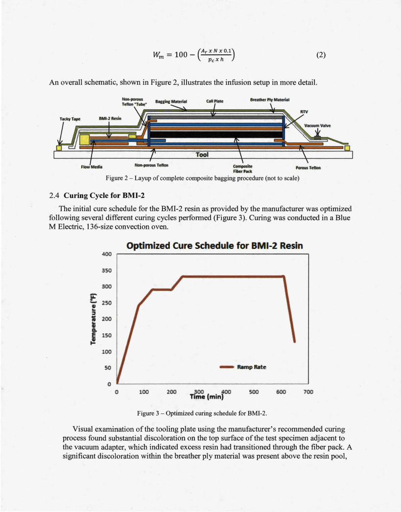
An overall schematic, shown in Figure 2, illustrates the infusion setup in more detail.
Colnposite L'orous Teftoll FilletPKk
Figure 2 - Layup of complete composite bagging procedure (not to scale)
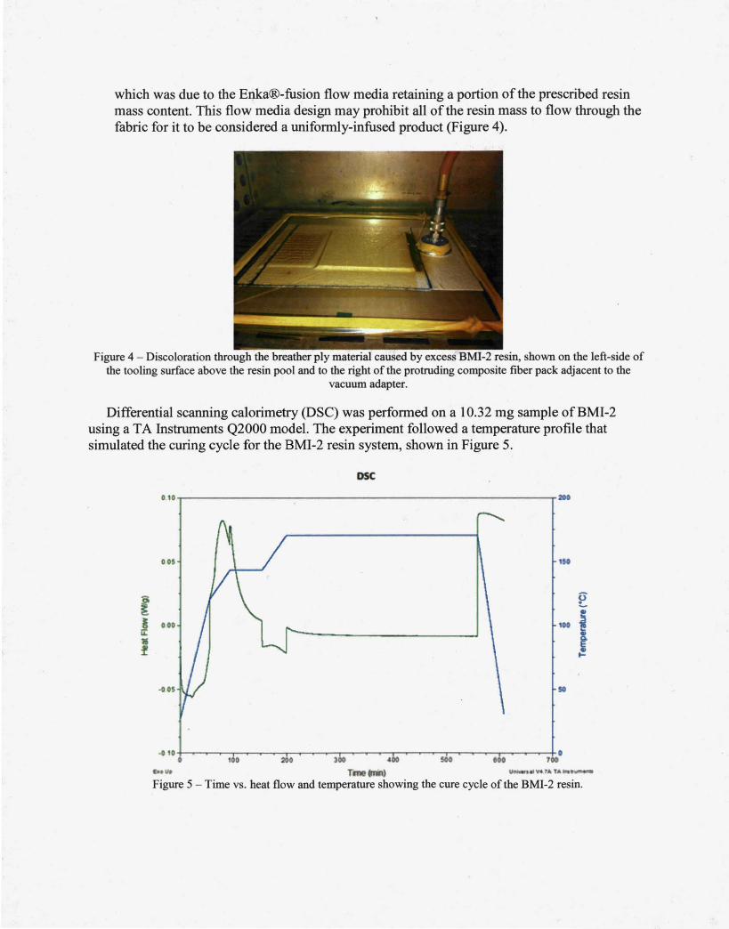
2.4 Curing Cycle for BMI-2
The initial cure schedule for the BMI-2 resin as provided by the manufacturer was optimized following several different curing cycles performed (Figure 3). Curing was conducted in a Blue M Electric, 136-size convection oven.
Optimized Cure Schedule for B 1-2 Resin 400
350
300
F 2SO -..
::J
= 200
G.
~ 150
100
so RMnpRirte
0 0 100 200 300 ~
Tim . (min) 500 600 700
Figure 3 - Optimized curing schedule for BMI-2.
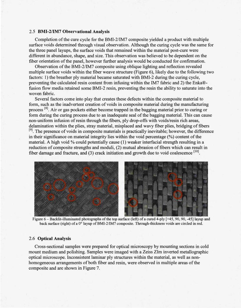
Visual examination of the tooling plate using the manufacturer's recommended curing process found substantial discoloration on the top surface of the test specimen adjacent to the vacuum adapter, which indicated excess resin had transitioned through the fiber pack. A significant discoloration within the breather ply material was present above the resin pool,
which was due to the Enka®-fusion flow media retaining a portion of the prescribed resin mass content. This flow media design may prohibit all of the resin mass to flow through the fabric for it to be considered a uniformly-infused product (Figure 4).
Figure 4 - Discoloration through the breather ply material caused by excess BMI-2 resin, shown on the left-side of the tooling surface above the resin pool and to the right of the protruding composite fiber pack adjacent to the
vacuum adapter.
Differential scanning calorimetry (DSC) was performed on a 10.32 mg sample ofBMI-2 using a T A Instruments Q2000 model. The experiment followed a temperature profile that simulated the curing cycle for the BMI-2 resin system, shown in Figure 5.
DSC
010~-------------------------------------------------ra•
00$ 1$0
f E 5 010 , 0 j ti: • f
-on so
.,. Ti ' ) oJ .... f A TAINI
Figure 5 - Time vs. heat flow and temperature showing the cure cycle of the BMI-2 resin.
2.5 BMI-2/IM7 Observational Analysis
Completion of the cure cycle for the BMI-2/IM7 composite yielded a product with multiple surface voids determined through visual observation. Although the curing cycle was the same for the three panellayups, the surface voids that remained within the material post-cure were different in abundance, shape, and size. This observation was believed to be dependent on the fiber orientation of the panel, however further analysis would be conducted for confirmation.
Observation of the BMI-2/IM7 composite using oblique lighting and reflection revealed multiple surface voids within the fiber weave structure (Figure 6), likely due to the following two factors: 1) the breather ply material became saturated with BMI-2 during the curing cycle, preventing the calculated resin content from infusing within the IM7 fabric and 2) the Enka®fusion flow media retained some BMI-2 resin, preventing the resin the ability to saturate into the woven fabric.
Several factors come into play that creates these defects within the composite material to form, such as the inadvertent creation of voids in composite material during the manufacturing process [81 . Air or gas pockets either become trapped in the bagging material prior to curing or form during the curing process due to an inadequate seal of the bagging material. This can cause non-uniform infusion of resin through the fibers, ply drop-offs with voids/resin rich areas, delamination within the plies, stray material, misplaced and wavy fiber plies, bridging of fibers [91. The presence of voids in composite materials is practically inevitable; however, the difference in their significance on material integrity lies within the void percentage(%) content of the material. A high void% could potentially cause (1) weaker interfacial strength resulting in a reduction of composite strengths and moduli, (2) mutual abrasion of fibers which can result in fiber damage and fracture, and (3) crack initiation and growth due to void coalescence [101 .
Figure 6 - Backlit-illuminated photographs of the top surface (left) of a cured 4-ply [ +45, 90, 90, -45] layup and back surface (right) of a 0° layup ofBMI-2/IM7 composite. Through-thickness voids are circled in red.
2.6 Optical Analysis
Cross-sectional samples were prepared for optical microscopy by mounting sections in cold mount medium and polishing. Samples were imaged with a Zeiss Zlm inverted metallographic optical microscope. Inconsistent laminar ply structures within the material, as well as nonhomogeneous arrangements ofboth fiber and resin, were observed in multiple areas of the composite and are shown in Figure 7.
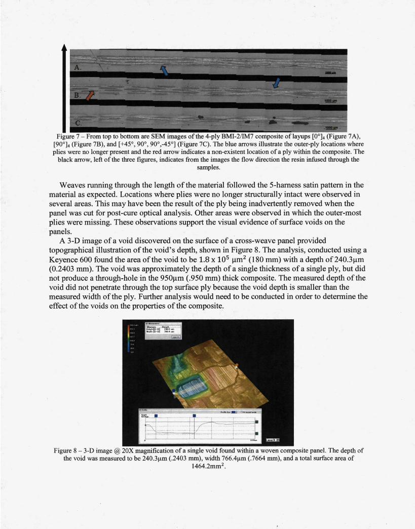
Figure 7 - From top to bottom are SEM images of the 4-ply BMI-2/IM7 composite of layups [0°]4 (Figure 7 A), [90°]4 (Figure 7B), and [+45°, 90°, 90°,-45°] (Figure 7C). The blue arrows illustrate the outer-ply locations where plies were no longer present and the red arrow indicates a non-existent location of a ply within the composite. The
black arrow, left of the three figures, indicates from the images the flow direction the resin infused through the samples.
Weaves running through the length of the material followed the 5-hamess satin pattern in the material as expected. Locations where plies were no longer structurally intact were observed in several areas. This may have been the result ofthe ply being inadvertently removed when the panel was cut for post-cure optical analysis. Other areas were observed in which the outer-most plies were missing. These observations support the visual evidence of surface voids on the panels.
A 3-D image of a void discovered on the surface of a cross-weave panel provided topographical illustration of the void's depth, shown in Figure 8. The analysis, conducted using a Keyence 600 found the area ofthe void to be 1.8 x 10⁵ )1m2 (180 mm) with a depth of240.3Jlm (0.2403 mm). The void was approximately the depth of a single thickness of a single ply, but did not produce a through-hole in the 950J..Lm (.950 mm) thick composite. The measured depth of the void did not penetrate through the top surface ply because the void depth is smaller than the measured width of the ply. Further analysis would need to be conducted in order to determine the effect of the voids on the properties of the composite.
Figure 8 - 3-D image @ 20X magnification of a single void found within a woven composite panel. The depth of the void was measured to be 240.3J.1m (.2403 mm), width 766.4J.Lm (.7664 mm), and a total surface area of
1464.2mm2•
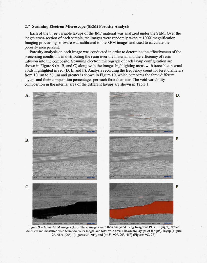
2.7 Scanning Electron Microscope (SEM) Porosity Analysis
Each of the three variable layups of the IM7 material was analyzed under the SEM. Over the length cross-section of each sample, ten images were randomly taken at 1 OOX magnification. Imaging processing software was calibrated to the SEM images and used to calculate the porosity area percent.
Porosity analysis on each image was conducted in order to determine the effectiveness of the processing conditions in distributing the resin over the material and the efficiency of resin infusion into the composite. Scanning electron micrograph of each layup configuration are shown in Figure 9 (A, B, and C) along with the images highlighting areas with traceable internal voids highlighted in red (D, E, and F). Analysis recording the frequency count for feret diameters from 10 J..Lm to 50 J..Lm and greater is shown in Figure 10, which compares the three different layups and their composition percentages per each feret diameter. The void variability composition in the internal area of the different layups are shown in Table 1.
A. D.
B. E.
C. F.
Figure 9 - Actual SEM images (left). These images were then analyzed using lmagePro Plus 6.1 (right), which detected and measured void ferret diameter length and total void area. Shown are layups of the [0°]4 layup (Figure
9A, 9D), [90°]4 (Figures 9B, 9E), and [+45°, 90°, 90°,-45°] (Figures 9C, 9F).
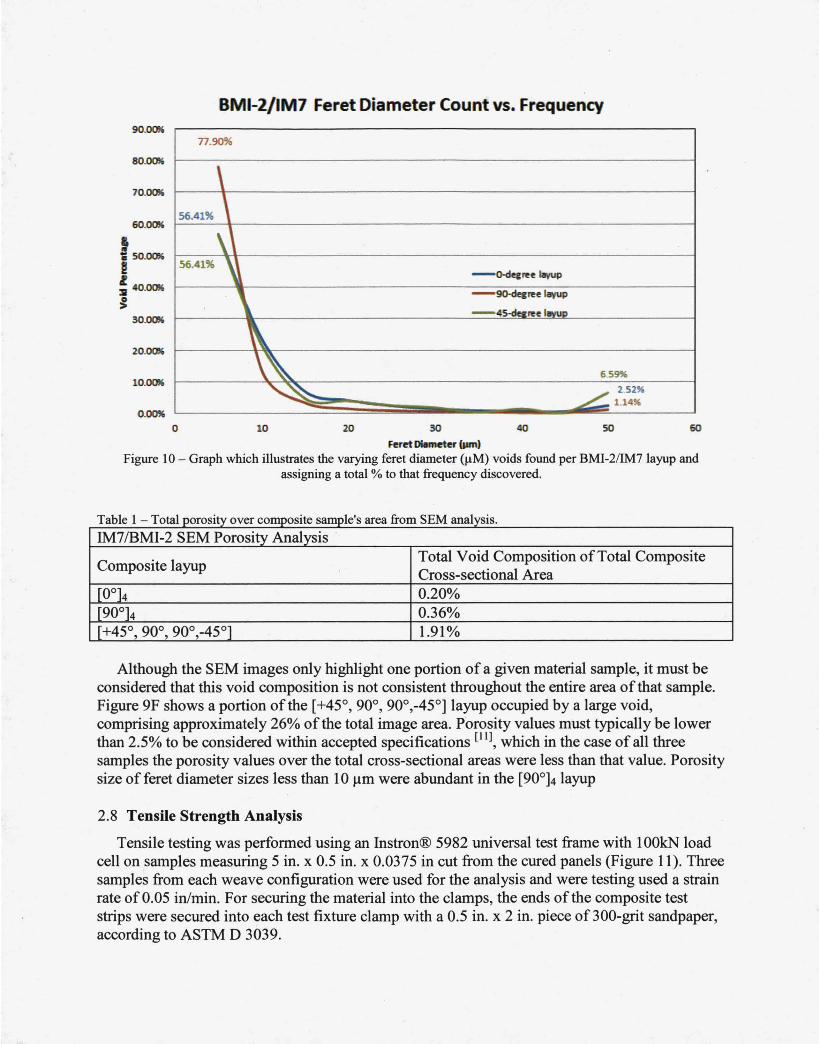
BMI-2/IM7 Feret Diameter Count vs. Frequency 90.0!a
80.0!a
70.()(a
60.0!a
t a SO.IXB'
! l :II 40.0!a
~ 30.1XB'
20.0!a
lO.O!a
0
77.90%
\ 56.41% \
\' 56.41% '
l
\ , - o-decn!e p
- 90-decn!e IIIVUP
-4~n!e IIMIP
\
''" 65~
~ ..L. 2.52" 1.14"
10 20 30 40 50 60
Feret Diameter {pm)
Figure 10 - Graph which illustrates the varying feret diameter (J..LM) voids found per BMI-2/IM7 layup and assigning a total % to that frequency discovered.
Table 1 - Totalporosity over composite sample's area fr om SEM analysis.
IM7/BMI-2 SEM Porosity Analysis .
Composite layup Total Void Composition ofTotal Composite Cross-sectional Area
f0°l4 0.20% [90°]4 0.36% [+45° 90° 90°-45°] , , , 1.91%
Although the SEM images only highlight one portion of a given material sample, it must be considered that this void composition is not consistent throughout the entire area of that sample. Figure 9F shows a portion ofthe [+45°, 90°, 90°,-45°] layup occupied by a large void, comprising approximately 26% of the total image area. Porosity values must typically be lower than 2.5% to be considered within accepted specifications [IIJ, which in the case of all three samples the porosity values over the total cross-sectional areas were less than that value. Porosity size of feret diameter sizes less than 10 J.tm were abundant in the [90°]4 layup
2.8 Tensile Strength Analysis
Tensile testing was performed using an Instron® 5982 universal test frame with 1 OOkN load cell on samples measuring 5 in. x 0.5 in. x 0.0375 in cut from the cured panels (Figure 11). Three samples from each weave configuration were used for the analysis and were testing used a strain rate of0.05 in/min. For securing the material into the clamps, the ends of the composite test strips were secured into each test fixture clamp with a 0.5 in. x 2 in. piece of 300-grit sandpaper, according to ASTM D 3039.
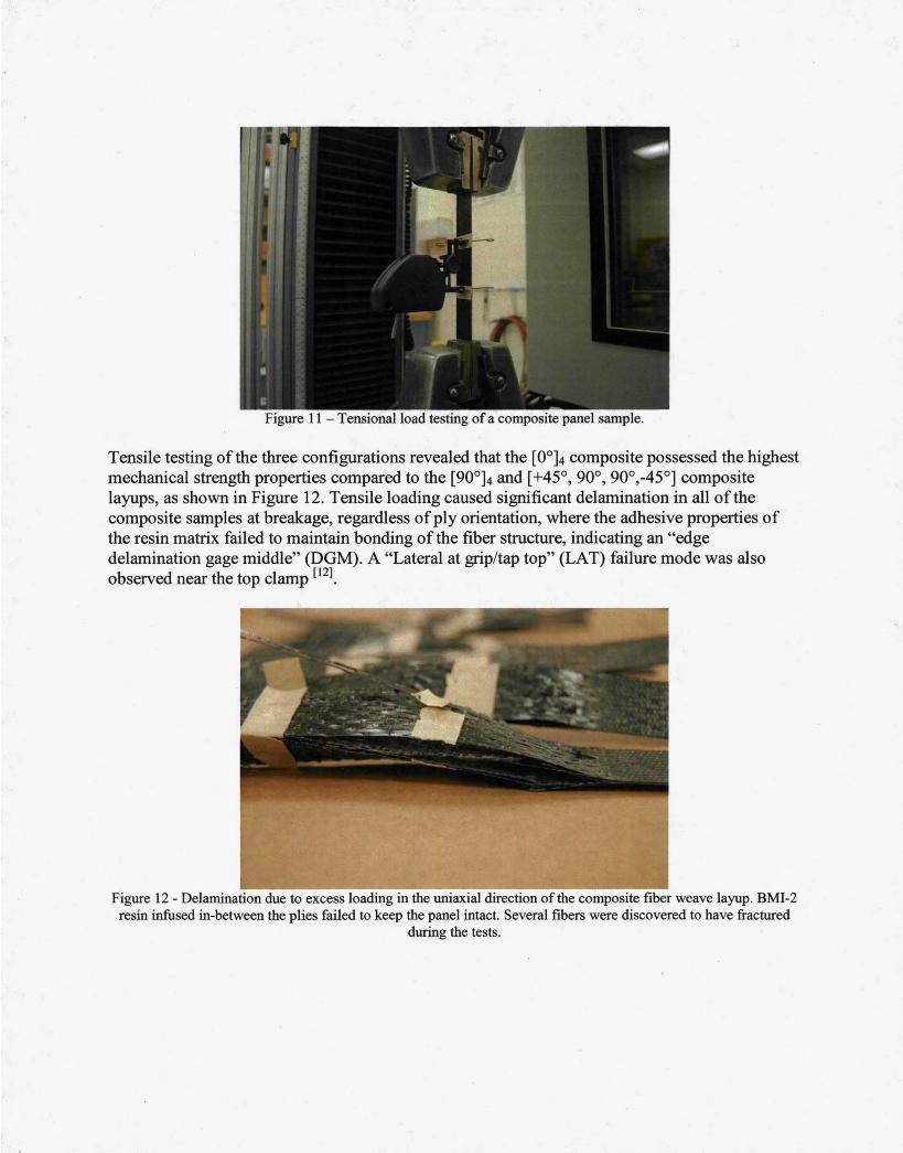
Figure 11 -Tensional load testing of a composite panel sample.
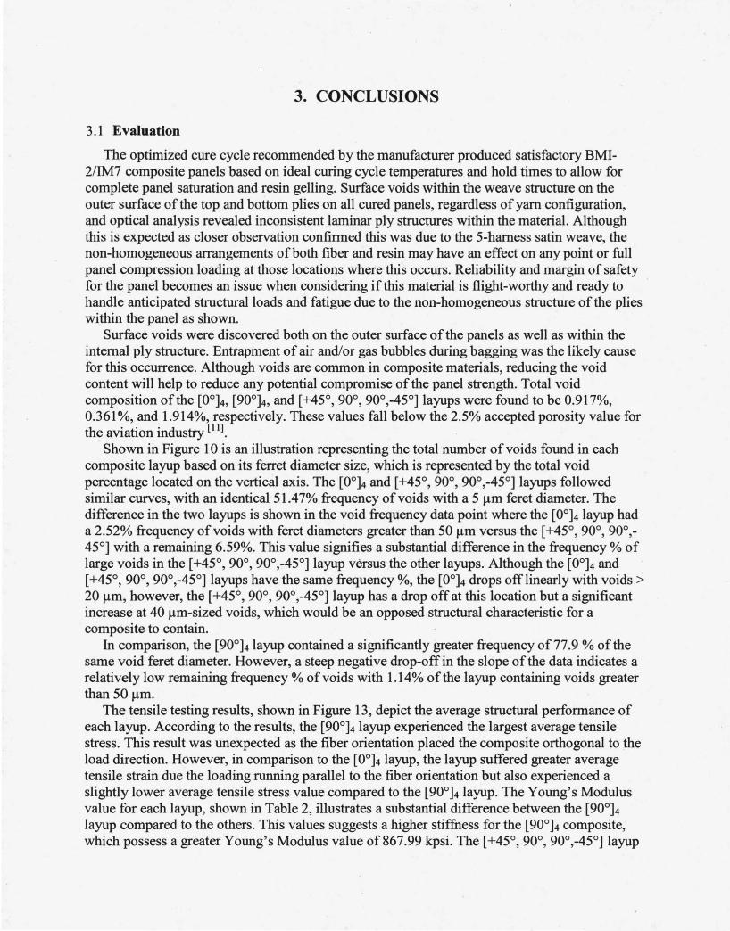
Tensile testing of the three configurations reveal~d that the [0°]4 composite possessed the highest mechanical strength properties compared to the [90°]4 and [+45°, 90°, 90°,-45°] composite layups, as shown in Figure 12. Tensile loading caused significant delamination in all of the composite samples at breakage, regardless of ply orientation, where the adhesive properties of the resin matrix failed to maintain bonding of the fiber structure, indicating an "edge delamination gage middle" (DGM). A "Lateral at grip/tap top" (LAT) failure mode was also observed near the top clamp [!21.
Figure 12- Delamination due to excess loading in the uniaxial direction of the composite fiber weave layup. BMI-2 resin infused in-between the plies failed to keep the panel intact. Several fibers were discovered to have fractured
during the tests.
3. CONCLUSIONS
3 .1 Evaluation
The optimized cure cycle recommended by the manufacturer produced satisfactory BMI-2/IM7 composite panels based on ideal curing cycle temperatures and hold times to allow for complete panel saturation and resin gelling. Surface voids within the weave structure on the outer surface of the top and bottom plies on all cured panels, regardless of yarn configuration, and optical analysis revealed inconsistent laminar ply structures within the material. Although this is expected as closer observation confirmed this was due to the 5-harness satin weave, the non-homogeneous arrangements of both fiber and resin may have an effect on any point or full panel compression loading at those locations where this occurs. Reliability and margin of safety for the panel becomes an issue when considering if this material is flight-worthy and ready to handle anticipated structural loads and fatigue due to the non-homogeneous structure of the plies within the panel as shown.
Surface voids were discovered both on the outer surface of the panels as well as within the internal ply structure. Entrapment of air and/or gas bubbles during bagging was the likely cause for this occurrence. Although voids are common in composite materials, reducing the void content will help to reduce any potential compromise of the panel strength. Total void composition of the [0°]4, [90°]4, and [ +45°, 90°, 90°,-45°] layups were found to be 0.917%, 0.361%, and 1.914%, respectively. These values fall below the 2.5% accepted porosity value for the aviation industry [Ill.
Shown in Figure 1 0 is an illustration representing the total number of voids found in each composite layup based on its ferret diameter size, which is represented by the total void percentage located on the vertical axis. The [0°]4 and [+45°, 90°, 90°,-45°] layups followed similar curves, with an identical51.47% frequency of voids with a 5 Jlm feret diameter. The difference in the two layups is shown in the void frequency data point where the [0°]4 layup had a 2.52% frequency of voids with feret diameters greater than 50 Jlm versus the [+45°, 90°, 90°,-450] with a remaining 6.59%. This value signifies a substantial difference in the frequency % of large voids in the [+45°, 90°, 90°,-45°] layup versus the other layups. Although the [0°]4 and [+45°, 90°, 90°,-45°] layups have the same frequency%, the [0°]4 drops off linearly with voids> 20 Jlm, however, the [ +45°, 90°, 90° ,-45°] layup has a drop off at this location but a significant increase at 40 Jlm-sized voids, which would be an opposed structural characteristic for a composite to contain.
In comparison, the [90°]4 layup contained a significantly greater frequency of 77.9 % of the same void feret diameter. However, a steep negative drop-off in the slope of the data indicates a relatively low remaining frequency% of voids with 1.14% of the layup containing voids greater than 50 Jlm.
The tensile testing results, shown in Figure 13, depict the average structural performance of each layup. According to the results, the [90°]4 layup experienced the largest average tensile stress. This result was unexpected as the fiber orientation placed the composite orthogonal to the load direction. However, in comparison to the [0°]4 layup, the layup suffered greater average tensile strain due the loading running parallel to the fiber orientation but also experienced a slightly lower average tensile stress value compared to the [90°]4 layup. The Young's Modulus value for each layup, shown in Table 2, illustrates a substantial difference between the [90°]4
layup compared to the others. This values suggests a higher stiffness for the [90°]4 composite, which possess a greater Young's Modulus value of867.99 kpsi. The [+45°, 90°, 90°,-45°] layup
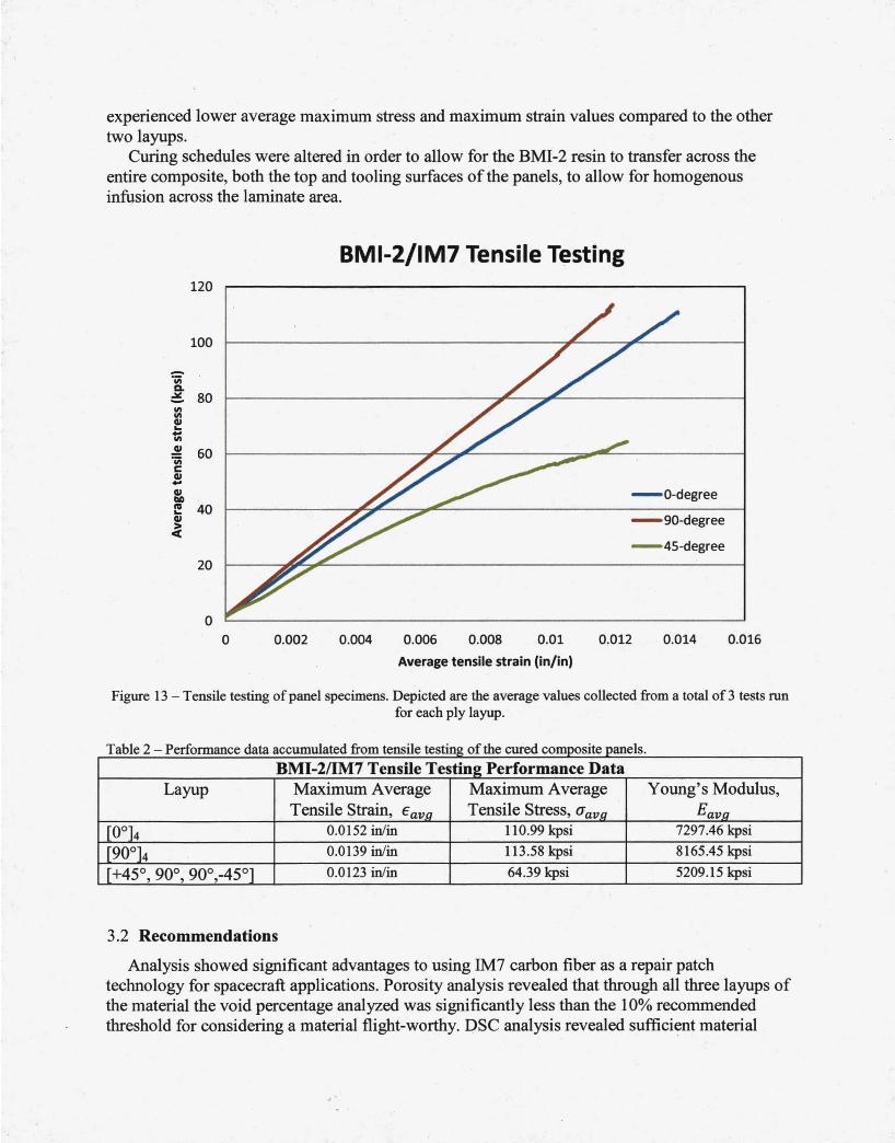
experienced lower average maximum stress and maximum strain values compared to the other two layups.
Curing schedules were altered in order to allow for the BMI-2 resin to transfer across the entire composite, both the top and tooling surfaces of the panels, to allow for homogenous infusion across the laminate area.
BMI-2/IM7 Tensile Testing 120
100
-'iii a. ; 80 Ill Ill Gl ... t; .!! 60 'iii c Gl .. Gl - a -degree 110 ftl 40 ... Gl - 90-degree ~
- 45-degree 20
0
0 0.002 0.004 0.006 0.008 0.01 0.012 0.014 0.016
Average tensile strain (in/in)
Figure 13 - Tensile testing of panel specimens. Depicted are the average values collected from a total of3 tests run for each ply layup.
a e - e ormance T bl 2 P r£ ta accumu ate om tens e testing o 1 d fr il da fth d e cure composite pane s.
BMI-2/IM7 Tensile Testing Performance Data Layup Maximum Average Maximum Average Young's Modulus,
Tensile Strain, Eav,q Tensile Stress, aavg Eav,q
[0°]4 0.0152 in/in 110.99 kpsi 7297.46 kpsi
[90°]4 0.0139 in/in 113.58 kpsi 8165.45 kpsi
[+45° 90° 90°-45°] 0.0123 in/in 64.39 kpsi 5209.15 kpsi ' ' '
3.2 Recommendations
Analysis showed significant advantages to using IM7 carbon fiber as a repair patch technology for spacecraft applications. Porosity analysis revealed that through all three layups of the material the void percentage analyzed was significantly less than the 10% recommended threshold for considering a material flight-worthy. DSC analysis revealed sufficient material
density within the material to prevent air or gas concentrations from accumulating within the material due to heat flow values as high as O.og Wig. This value shows an insignificant exothermic reaction as the resin is raised in temperature. Strength properties of the BMI-2/IM7 material displayed excellent stress and strain properties. Specifically, the [0°]4 layup had an }g_g% and 21.7% greater average tensile strain performance compared to the [g0°]4 and [+45°, goo, goo,-45°] layups, respectively, at failure. For tensile stress performance, the [0°]4 layup had a 5.8% and 34.0% greater average performance% than the [g0°]4 and [+45°, goo·, goo,-45°] layups.
Curing of the BMI-2/IM7 system utilized an optimal infusion process which focused on the integration of the manufacturer-recommended ramp rates, hold times, and cure temperatures. However, during the manufacturing process for which the fabric and resin was prepped, it is suspected that unintended air and/or gas entrapment occurred during the bagging procedure. Although this paper focuses in on the optimization of the curing schedule of the BMI-2/IM7 system, results recovered from void analysis following the cure anticipated do not take into account possible voids that had formed within the composite due to these air/gas pockets being present. The void percentage values calculated considered an optimized curing process coupled with a non-optimized procedure for air/gas removal unintentional void creation. It is recommended for future curing cycles that an optilnized procedure for air/ gas removal from the bagged system be constructed, which would include the creation on an optimal percentage for air/gas removal. The vacuum pump used in the procedure must be calibrated in order to meet that optimal value.
From the results, it can be interpreted that the BMI-2/IM7 composite would serve as an adequate material for repair patch work. Loading on the material must be considered when applying the material to its specified application. A uniaxial configuration of the plies must be considered when applying the material to the intended surface as it is recommended the yarn length run parallel with the anticipated loading direction on the surface of the material. Areal elongation due to structural and thermal loading, although minimal, is expected to occur. Additionally, research should be conducted to compare existing material-resin systems and their expected structural and thermal resistant properties to determine if the BMI-2/IM7 system is compatible for application of spacecraft repair patch work.
This project was supported through NASA's Composites for Exploration Project. The authors of this paper would like to thank Dr. James Sutter (NASA Glenn Research Center), Dr. Sandi Miller (NASA Glenn Research Center}, and Linas Repecka ofRaptor Resins.
4. REFERENCES
1. Stenzenberger, Horst. "Bismaleimide Resins." Constituent Materials Chapters from ASM Handbook. Iowa State University, College ofEngineering, 104 Marston Hall, Ames, Iowa 50011. February 4, 2013. http://home.engineering.iastate.edu/~mkessler/MatE454/Constituent%20Materials%20Chapt ers%20from%20ASM%20Handbook/%286%29%20Bismaleimide%20Resins.pdf.
2. Aerospace Repair Analysis & Substantiation. Kress Precision Composites, 2012.
3. Baker, Dr. Alan; Chester, Dr. Richard; Mazza, James. "Bonded Repair Technology for Aging Aircraft." Life Management Techniques for Aging Air Vehicles. RTO A VT Specialists' Meeting, Manchester, United Kingdom, October 8-11, 200l.RTO-MP-079(11).
4. Ihn, Jeong-Beohm; Soutis, Constantinos. "Design, Analysis, and SHM of Bonded Composite Repair and Substructure." Wiley Online Library. September 15, 2009. Encyclopedia of Structural Health Monitoring, John Wiley &Sons, pp.2. February 4, 2013. http://onlinelibrary.wiley.com/doi/1 0.1 002/9780470061626.shm145/full.
5. "Instructions, BMI Resin infusion." Raptor Resins Inc. 2008. September 15, 2012. http:/ /raptorresins.com/index.htm.
6. "Resin Properties for Composite Materials." Azom.com: The A to Z of Materials. SP Systems. October 26, 2001. September 15, 2012. http://www .azom.com/article.aspx? ArticleiD=997.
7. [5] ASTM Standard D3171- 09, 2012, "Standard Test Method for Constituent Content of Composite Materials" ASTM International, 100 Barr Harbor Drive, PO Box C700, West
· Conshohocken, PA 19428, 2012, DOl: E47.01/D3171 -09, www.astm.org.
8. "Composite Basics: Materials." American Composite Manufacturers Association. 2004. http:/ /www.mdacomposites.org/mda/psgbridge _ CB _ Materials2 _ Resins.html. September 2012.
9. Smith, R.A. Composite Defects and Their Detection. 1994. September 15,2012. http://www .desware.net/Sample-Chapters/D07/E6-3 6-04-03 .pdf.
10. Beckwith, Dr. Scott W. "Manufacturing Defects in Composite Structures." 2012. SAMPE Journal, Volume 48, No.5, September/October 2012. SAMPE: Society for the Advancement of Material and Process Engineering. pp.53. September 18, 2012. http://www .sampe.org/news/TechTidbitsSept12.pd£
11. Kastner, Johann; Plank, Bernhard; Salaberger, Dietmar; Sekelja, Jakov. "Defect and Porosity Determination of Fibre Reinforced Polymers by X-ray Computed Tomography". 2nd
International Symposium on NDT in Aerospace 2010. Radison Blu Hotel, Hamburg Airport, Germany, November 22-24,2010. NDT in Aerospace, pp. 1-12.

12. ASTM Standard D3039/D3039M - 08, 2010, "Standard Method for Tensile Properties of Polymer Matrix Composite Materials" ASTM International, 100 Barr Harbor Drive, PO Box C700, West Conshohocken, P A 19428, 2012, DOl: D30.04/D3039/D3039M- 08, www.astm.org.


![AIR FORCE INSTITUTE OF TECHNOLOGY · The effect of prior aging on the mechanical response of IM7/BMI 5250-4 graphite/bismaleimide composite with [±45] 4s and [0/90] 4s fiber orientation](https://img.pdfslide.net/doc/110x75/5ba151e209d3f2766b8c2026/air-force-institute-of-the-effect-of-prior-aging-on-the-mechanical-response.jpg)
![BM1弾 カードチェックリスト · 2020-06-17 · 1.89 d bmi-scp4[cp1 c] bmi-scp8[cp] bmi-hcpi bmi-scps[cpi a bmi cl bmi-scpi c] bmi-scp5[cp] c] bmi-cpi [cpi 12 bmi-cp2tcp]](https://img.pdfslide.net/doc/110x75/5f0d11867e708231d43885ac/bm1-fffffff-2020-06-17-189-d-bmi-scp4cp1-c-bmi-scp8cp.jpg)