Embed Size (px)
Citation preview
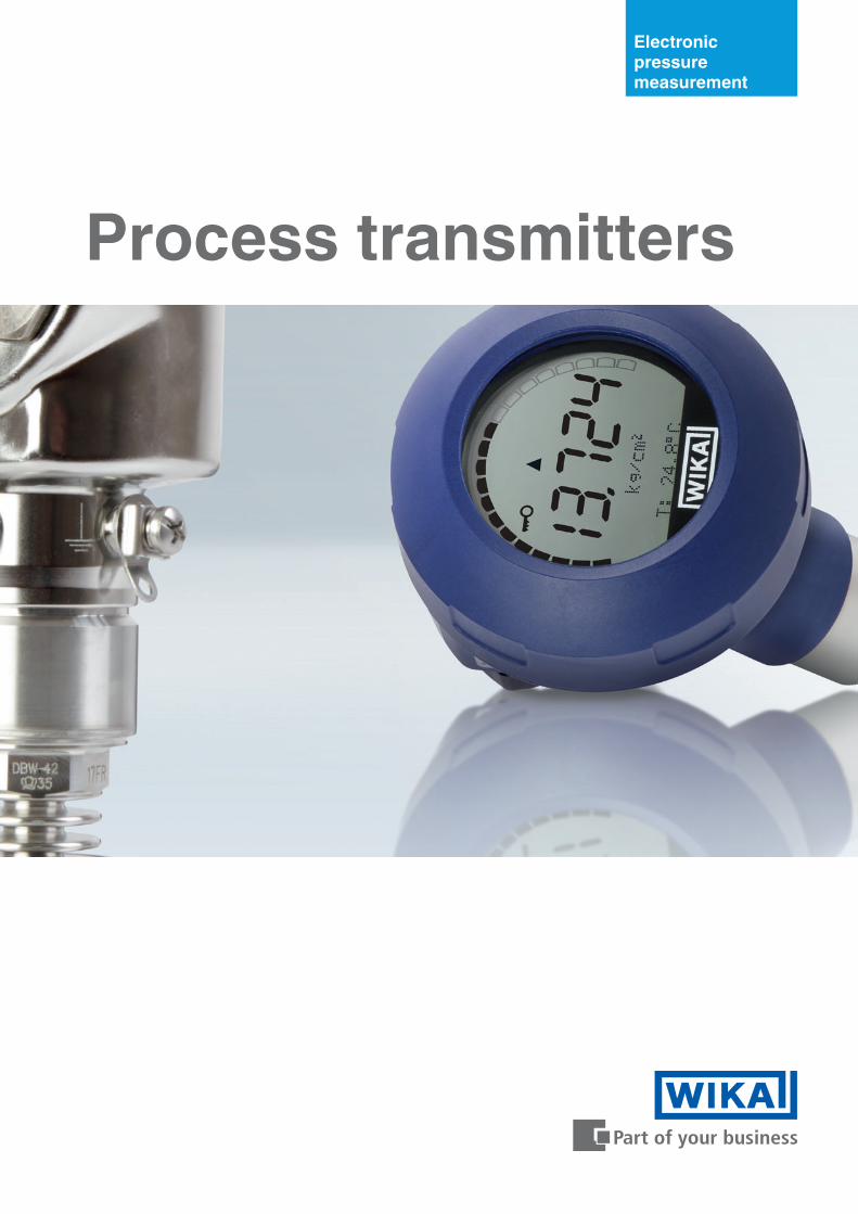
Electronic pressure measurement
Process transmitters
2
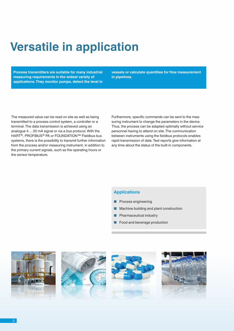
Process transmitters are suitable for many industrial measuring requirements in the widest variety of applications. They monitor pumps, detect the level in
vessels or calculate quantities for flow measurement in pipelines.
Versatile in application
The measured value can be read on site as well as being transmitted to a process control system, a controller or a terminal. The data transmission is achieved using an analogue 4 ... 20 mA signal or via a bus protocol. With the HART®, PROFIBUS® PA or FOUNDATION™ Fieldbus bus systems, there is the possibility to transmit further information from the process and/or measuring instrument, in addition to the primary current signals, such as the operating hours or the sensor temperature.
Furthermore, specific commands can be sent to the mea-suring instrument to change the parameters in the device. Thus, the process can be adapted optimally without service personnel having to attend on site. The communication between instruments using the fieldbus protocols enables rapid transmission of data. Test reports give information at any time about the status of the built-in components.
■ Process engineering
■ Machine building and plant construction
■ Pharmaceutical industry
■ Food and beverage production
Applications
3
Pharmaceutical water treatment
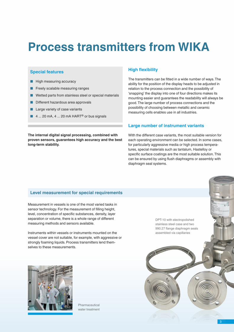
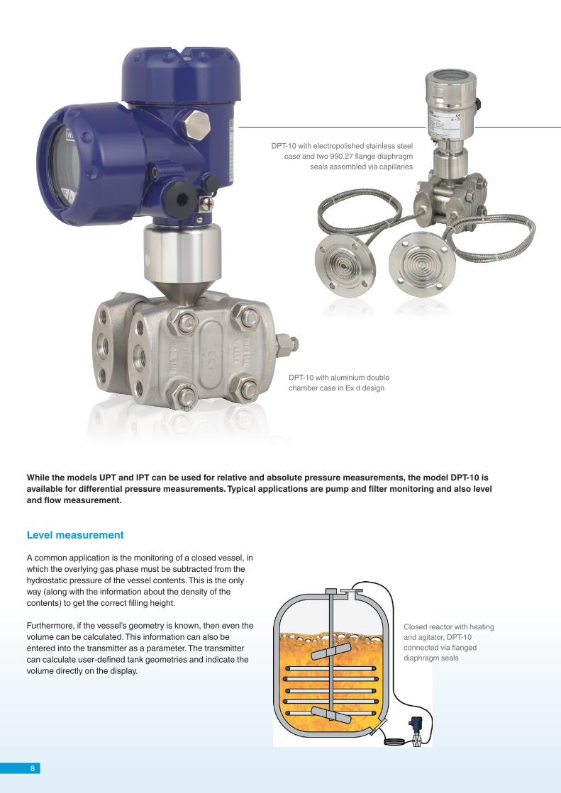
DPT-10 with electropolished stainless steel case and two 990.27 flange diaphragm seals assembled via capillaries
Process transmitters from WIKA
Level measurement for special requirements
The internal digital signal processing, combined with proven sensors, guarantees high accuracy and the best long-term stability.
Measurement in vessels is one of the most varied tasks in sensor technology. For the measurement of filling height, level, concentration of specific substances, density, layer separation or volume, there is a whole range of different measuring methods and sensors available.
Instruments within vessels or instruments mounted on the vessel cover are not suitable, for example, with aggressive or strongly foaming liquids. Process transmitters lend them-selves to these measurements.
Special features
■ High measuring accuracy
■ Freely scalable measuring ranges
■ Wetted parts from stainless steel or special materials
■ Different hazardous area approvals
■ Large variety of case variants
■ 4 ... 20 mA, 4 ... 20 mA HART® or bus signals
High flexibility
The transmitters can be fitted in a wide number of ways. The ability for the position of the display heads to be adjusted in relation to the process connection and the possibility of ‘snapping’ the display into one of four directions makes its mounting easier and guarantees the readability will always be good. The large number of process connections and the possibility of choosing between metallic and ceramic measuring cells enables use in all industries.
Large number of instrument variants
With the different case variants, the most suitable version for each operating environment can be selected. In some cases, for particularly aggressive media or high process tempera-tures, special materials such as tantalum, Hastelloy or specific surface coatings are the most suitable solution. This can be ensured by using flush diaphragms or assembly with diaphragm seal systems.

4
Wide range of applications Excellent readability
This measuring instrument is as suited to machine building and plant construction as it is for the traditional areas for process transmitters. The UPT also finds its place in chemical plants, especially in the Ex ia version (intrinsically safe design). With flush process connections, the requirements of the hygienic, pharmaceutical and food industries are fulfilled. The instrument is available with analogue output signal or with HART® protocol to the latest HART® v7 revision.
The case of the UPT is rotatable around the connection so that the ideal orientation towards the viewer can be made, even after mounting to the process. The electrical installation is possible on site without the aid of tools. The instrument has a high-contrast, clear and particularly large display. With a 58 mm diameter, it is the largest on the market. The digits of the main display, with a character height of 14 mm, can be read easily from a distance. With a tilt angle for the display of 45°, reading from both the front and from above are equally possible without needing any modification to the display.
UPT-20 with display and G 1/2 B process connection
5
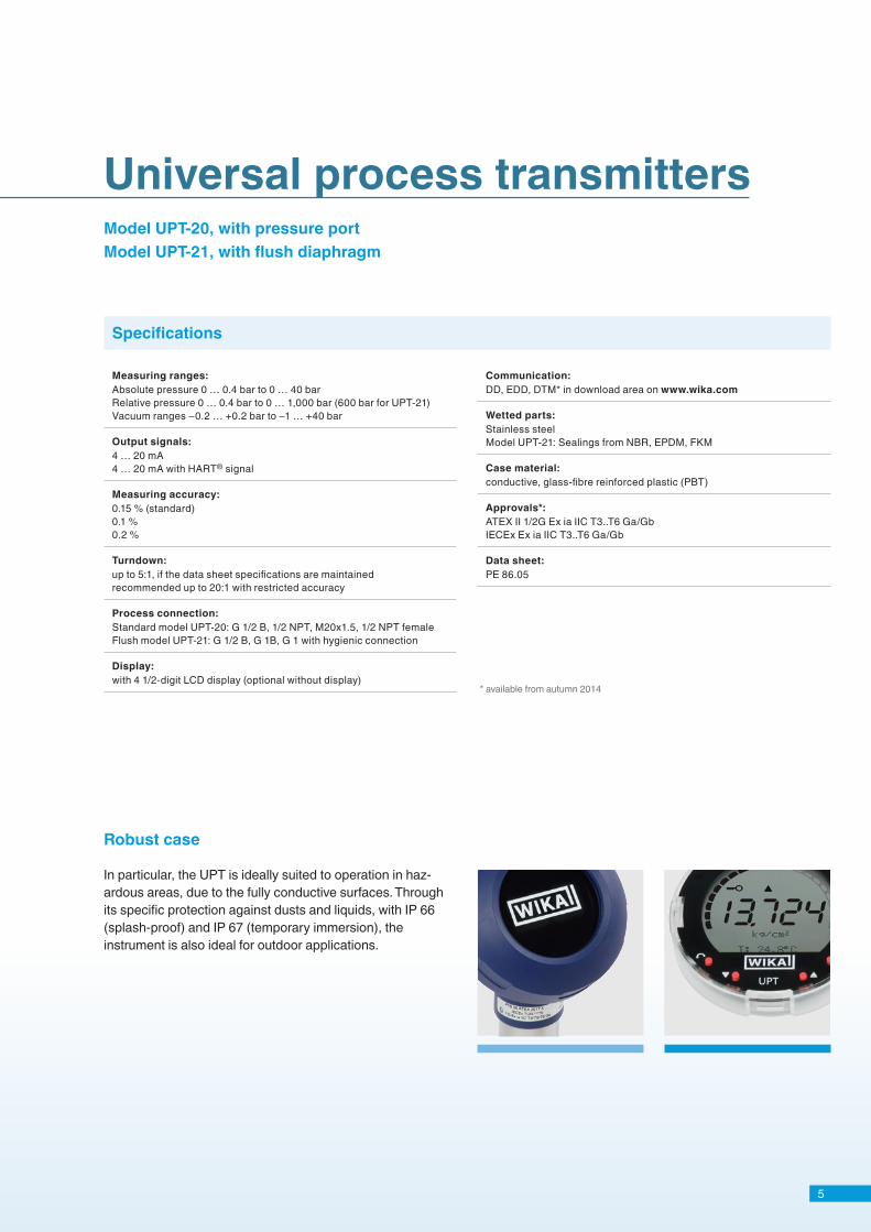
Robust case
Universal process transmitters
In particular, the UPT is ideally suited to operation in haz-ardous areas, due to the fully conductive surfaces. Through its specific protection against dusts and liquids, with IP 66 (splash-proof) and IP 67 (temporary immersion), the instrument is also ideal for outdoor applications.
Model UPT-20, with pressure portModel UPT-21, with flush diaphragm
Specifications
Measuring ranges:Absolute pressure 0 … 0.4 bar to 0 … 40 barRelative pressure 0 … 0.4 bar to 0 … 1,000 bar (600 bar for UPT-21)Vacuum ranges −0.2 … +0.2 bar to −1 … +40 bar
Output signals:4 … 20 mA4 … 20 mA with HART® signal
Measuring accuracy:0.15 % (standard)0.1 %0.2 %
Turndown:up to 5:1, if the data sheet specifications are maintainedrecommended up to 20:1 with restricted accuracy
Process connection:Standard model UPT-20: G 1/2 B, 1/2 NPT, M20x1.5, 1/2 NPT femaleFlush model UPT-21: G 1/2 B, G 1B, G 1 with hygienic connection
Display:with 4 1/2-digit LCD display (optional without display)
Communication:DD, EDD, DTM* in download area on www.wika.com
Wetted parts:Stainless steelModel UPT-21: Sealings from NBR, EPDM, FKM
Case material:conductive, glass-fibre reinforced plastic (PBT)
Approvals*:ATEX II 1/2G Ex ia IIC T3..T6 Ga/GbIECEx Ex ia IIC T3..T6 Ga/Gb
Data sheet:PE 86.05
* available from autumn 2014
6
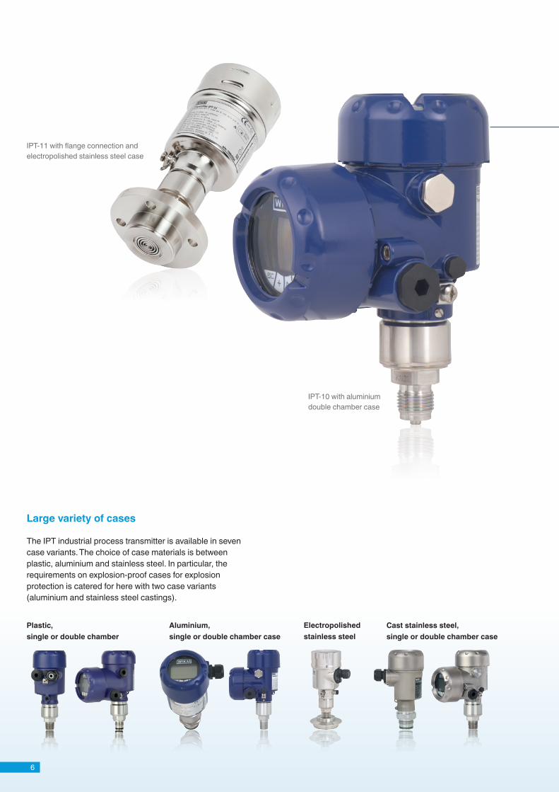
IPT-10 with aluminium double chamber case
IPT-11 with flange connection and electropolished stainless steel case
Large variety of cases
The IPT industrial process transmitter is available in seven case variants. The choice of case materials is between plastic, aluminium and stainless steel. In particular, the requirements on explosion-proof cases for explosion protection is catered for here with two case variants (aluminium and stainless steel castings).
Plastic, single or double chamber
Aluminium, single or double chamber case
Cast stainless steel, single or double chamber case
Electropolished stainless steel
7
Industrial process transmitters Model IPT-10, with pressure portModel IPT-11, with flush diaphragm
Specifications
Electronics Sensors
The electronics are available in four variants with an ana-logue output and three bus variants. In this way, all standard output signals in the process industry are covered.
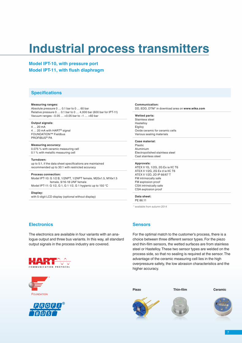
For the optimal match to the customer’s process, there is a choice between three different sensor types. For the piezo and thin-film sensors, the wetted surfaces are from stainless steel or Hastelloy. These two sensor types are welded on the process side, so that no sealing is required at the sensor. The advantage of the ceramic measuring cell lies in the high overpressure safety, the low abrasion characteristics and the higher accuracy.
Piezo Thin-film Ceramic
Measuring ranges:Absolute pressure 0 … 0.1 bar to 0 … 60 barRelative pressure 0 … 0.1 bar to 0 … 4,000 bar (600 bar for IPT-11)Vacuum ranges −0.05 … +0.05 bar to −1 … +60 bar
Output signals:4 … 20 mA4 … 20 mA with HART® signalFOUNDATION™ FieldbusPROFIBUS® PA
Measuring accuracy:0.075 % with ceramic measuring cell0.1 % with metallic measuring cell
Turndown:up to 5:1, if the data sheet specifications are maintainedrecommended up to 30:1 with restricted accuracy
Process connection:Model IPT-10: G 1/2 B, 1/2NPT, 1/2NPT female, M20x1.5, M16x1.5
female, 9/16-18 UNF femaleModel IPT-11: G 1/2, G 1, G 1 1/2, G 1 hygienic up to 150 °C
Display:with 5-digit LCD display (optional without display)
Communication:DD, EDD, DTM* in download area on www.wika.com
Wetted parts:Stainless steelHastelloyElgiloyOxide ceramic for ceramic cells Various sealing materials
Case material:PlasticAluminiumElectropolished stainless steelCast stainless steel
Approvals:ATEX II 1G, 1/2G, 2G Ex ia IIC T6ATEX II 1/2G, 2G Ex d ia IIC T6ATEX II 1/2D, 2D IP 66/67 TFM intrinsically safeFM explosion proofCSA intrinsically safeCSA explosion proof
Data sheet:PE 86.11
* available from autumn 2014
8
DPT-10 with aluminium double chamber case in Ex d design
A common application is the monitoring of a closed vessel, in which the overlying gas phase must be subtracted from the hydrostatic pressure of the vessel contents. This is the only way (along with the information about the density of the contents) to get the correct filling height.
Furthermore, if the vessel’s geometry is known, then even the volume can be calculated. This information can also be entered into the transmitter as a parameter. The transmitter can calculate user-defined tank geometries and indicate the volume directly on the display.
While the models UPT and IPT can be used for relative and absolute pressure measurements, the model DPT-10 is available for differential pressure measurements. Typical applications are pump and filter monitoring and also level and flow measurement.
Closed reactor with heating and agitator, DPT-10 connected via flanged diaphragm seals
Level measurement
DPT-10 with electropolished stainless steel case and two 990.27 flange diaphragm
seals assembled via capillaries
9
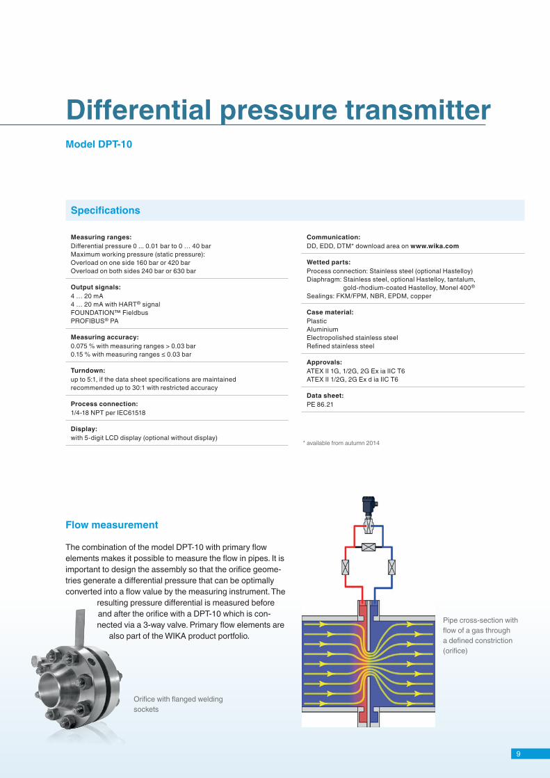
Differential pressure transmitterModel DPT-10
Specifications
Orifice with flanged welding sockets
Pipe cross-section with flow of a gas through a defined constriction (orifice)
The combination of the model DPT-10 with primary flow elements makes it possible to measure the flow in pipes. It is important to design the assembly so that the orifice geome-tries generate a differential pressure that can be optimally converted into a flow value by the measuring instrument. The
resulting pressure differential is measured before and after the orifice with a DPT-10 which is con-nected via a 3-way valve. Primary flow elements are
also part of the WIKA product portfolio.
Measuring ranges:Differential pressure 0 ... 0.01 bar to 0 … 40 barMaximum working pressure (static pressure):Overload on one side 160 bar or 420 barOverload on both sides 240 bar or 630 bar
Output signals:4 … 20 mA4 … 20 mA with HART® signalFOUNDATION™ FieldbusPROFIBUS® PA
Measuring accuracy:0.075 % with measuring ranges > 0.03 bar0.15 % with measuring ranges ≤ 0.03 bar
Turndown:up to 5:1, if the data sheet specifications are maintainedrecommended up to 30:1 with restricted accuracy
Process connection:1/4-18 NPT per IEC61518
Display:with 5-digit LCD display (optional without display)
Communication:DD, EDD, DTM* download area on www.wika.com
Wetted parts:Process connection: Stainless steel (optional Hastelloy)Diaphragm: Stainless steel, optional Hastelloy, tantalum,
gold-rhodium-coated Hastelloy, Monel 400®
Sealings: FKM/FPM, NBR, EPDM, copper
Case material:PlasticAluminiumElectropolished stainless steelRefined stainless steel
Approvals:ATEX II 1G, 1/2G, 2G Ex ia IIC T6ATEX II 1/2G, 2G Ex d ia IIC T6
Data sheet:PE 86.21
Flow measurement
* available from autumn 2014

10
Communication with process transmitters
For the WIKA UPT, IPT and DPT process transmitters, we recommend turndown values of up to 30:1. The stated basic accuracy is maintained to a max. of 5:1. Through clever selection of stock, this enables several applications to be covered with the same basic measuring range.
Freely scalable
Process Control Systems (PCS) are observing units that fully monitor, manage and control industrial plants (for example). All parameters and measured data related to the process are transmitted to a central point and evaluated according to a defined algorithm. A purely analogue output signal only enables the communication from the measuring instrument for control. With process transmitters with fieldbus interfaces, further possibilities are offered. The digital bus signal, or also the HART® protocol, enables bidirectional communication. The operator thus has the possibility to request specific parameters and, if necessary, also to change them. Therefore, for example, the measuring span of a process pressure transmitter can be matched to the process without needing any service personnel.
Fieldbus systems in process control technology
A bus instrument offers a further sizeable advantage: Through the scalability in the process or in the laboratory, a measuring instrument can be exchanged when it malfunc-tions and the stored data easily transferred to the new instrument. Through the reduction in service time and downtime connected with this, the operating costs can clearly be optimised.
11
Open, manufacturer-independent and fieldbus-independent user interface for operation and parameterisation of fieldbus devices.
For direct communication on site.
For communication between PC or notebook and the process transmitter via the HART® interface (USB, RS232, Bluetooth).
For communication over the HART® loop, for parameterisation of the measuring instruments, etc.
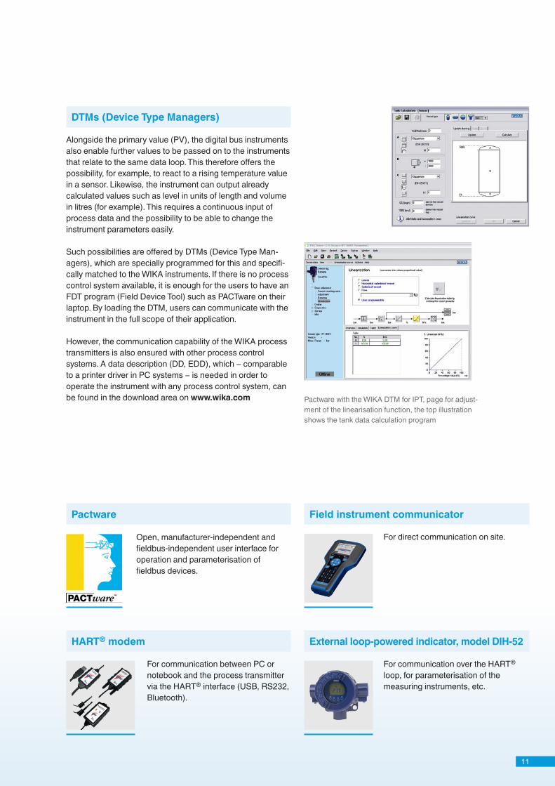
Pactware with the WIKA DTM for IPT, page for adjust-ment of the linearisation function, the top illustration shows the tank data calculation program
Alongside the primary value (PV), the digital bus instruments also enable further values to be passed on to the instruments that relate to the same data loop. This therefore offers the possibility, for example, to react to a rising temperature value in a sensor. Likewise, the instrument can output already calculated values such as level in units of length and volume in litres (for example). This requires a continuous input of process data and the possibility to be able to change the instrument parameters easily.
Such possibilities are offered by DTMs (Device Type Man-agers), which are specially programmed for this and specifi-cally matched to the WIKA instruments. If there is no process control system available, it is enough for the users to have an FDT program (Field Device Tool) such as PACTware on their laptop. By loading the DTM, users can communicate with the instrument in the full scope of their application.
However, the communication capability of the WIKA process transmitters is also ensured with other process control systems. A data description (DD, EDD), which − comparable to a printer driver in PC systems − is needed in order to operate the instrument with any process control system, can be found in the download area on www.wika.com
Pactware Field instrument communicator
HART® modem External loop-powered indicator, model DIH-52
DTMs (Device Type Managers)
WIKA Alexander Wiegand SE & Co. KGAlexander-Wiegand-Straße 30 / 63911 Klingenberg/GermanyTel. +49 9372 132-0 / Fax +49 9372 [email protected] / www.wika.com
14100924 04/2014 GB
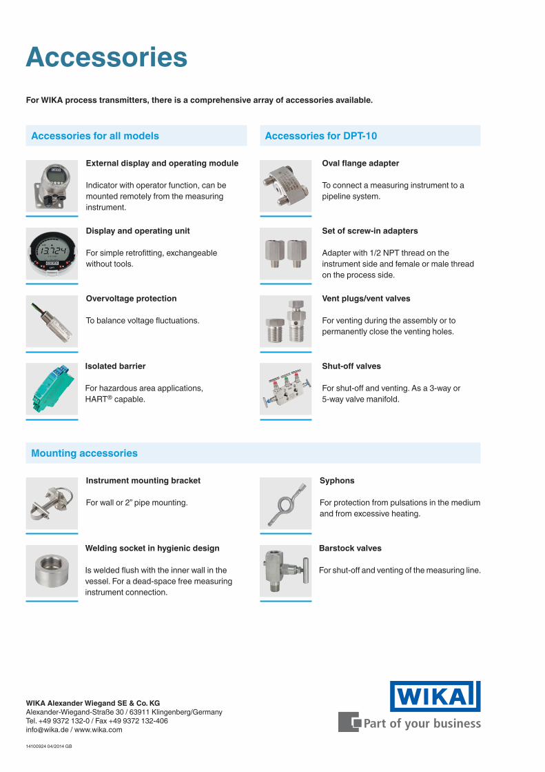
For WIKA process transmitters, there is a comprehensive array of accessories available.
Accessories
Accessories for all models
Mounting accessories
Accessories for DPT-10
External display and operating module
Indicator with operator function, can be mounted remotely from the measuring instrument.
Oval flange adapter
To connect a measuring instrument to a pipeline system.
Set of screw-in adapters
Adapter with 1/2 NPT thread on the instrument side and female or male thread on the process side.
Vent plugs/vent valves
For venting during the assembly or to permanently close the venting holes.
Shut-off valves
For shut-off and venting. As a 3-way or 5-way valve manifold.
Overvoltage protection
To balance voltage fluctuations.
Welding socket in hygienic design
Is welded flush with the inner wall in the vessel. For a dead-space free measuring instrument connection.
Barstock valves
For shut-off and venting of the measuring line.
Isolated barrier
For hazardous area applications, HART® capable.
Instrument mounting bracket
For wall or 2” pipe mounting.
Syphons
For protection from pulsations in the medium and from excessive heating.
Display and operating unit
For simple retrofitting, exchangeable without tools.