Embed Size (px)
Citation preview
Introduction:This manual covers the assembly, installation, startup, operation and maintenance of the 1200, 1400,1800 and 2000 remote low side cuber systems.
Keep this manual for future reference.
Prodigy Eclipse� 1200, 1400, 1800, 2000
August 2008Page 1
Table of Contents
Configuration· · · · · · · · · · · · · · · · · · Page 2
Technical Specifications · · · · · · · · · · · · Page 3
Model Number Locations · · · · · · · · · · · Page 4
Cabinet Drawings, Ice Making System · · · · Page 5
Cabinet Drawings, Compressor Package andCondensers · · · · · · · · · · · · · · · · · · Page 6
Proper Combinations: · · · · · · · · · · · · · Page 7
Create the System · · · · · · · · · · · · · · · Page 8
System Examples · · · · · · · · · · · · · · · Page 9
System Examples · · · · · · · · · · · · · · · Page 10
Place Remote System · · · · · · · · · · · · · Page 11
System Location · · · · · · · · · · · · · · · · Page 12
Route Tubing· · · · · · · · · · · · · · · · · · Page 13
Ice Making Section· · · · · · · · · · · · · · · Page 14
Compressor Package · · · · · · · · · · · · · Page 15
Condensing Section Assembly · · · · · · · · Page 16
Condensing Section Assembly · · · · · · · · Page 17
Ice making section: · · · · · · · · · · · · · · Page 18
Water and Drain · · · · · · · · · · · · · · · · Page 19
Water and Drain · · · · · · · · · · · · · · · · Page 20
Ice Making Section Set Up · · · · · · · · · · Page 21
Coupling Connections:· · · · · · · · · · · · · Page 22
Condensing Unit Connections · · · · · · · · · Page 23
Final Placement · · · · · · · · · · · · · · · · Page 24
Controller Operation · · · · · · · · · · · · · · Page 25
Initial Start Up · · · · · · · · · · · · · · · · · Page 26
Ice Bridge and Water Purge Adjustments · · · Page 27
Controller Information · · · · · · · · · · · · · Page 28
Use and Operation· · · · · · · · · · · · · · · Page 29
Control Switches · · · · · · · · · · · · · · · · Page 30
Options· · · · · · · · · · · · · · · · · · · · · Page 31
System Operation: · · · · · · · · · · · · · · · Page 32
Refrigeration Details: · · · · · · · · · · · · · Page 33
Technicians Only: Freeze Cycle Sequence of OperationPage 34
Technicians Only: Harvest Cycle Sequence ofOperation · · · · · · · · · · · · · · · · · · · Page 35
Control Safeties · · · · · · · · · · · · · · · · Page 36
Controller Operation · · · · · · · · · · · · · · Page 37
Cleaning, Sanitation and Maintenance · · · · Page 38
Service Diagnosis · · · · · · · · · · · · · · · Page 40
Service Diagnosis · · · · · · · · · · · · · · · Page 41
Service Diagnosis · · · · · · · · · · · · · · · Page 42
Operational Characteristics 1200 lb system · · Page 43
Operational Characteristics 1400 lb system · · Page 44
Operational Characteristics 1800 lb system · · Page 45
Operational Characteristics 2000 lb system · · Page 46
Refrigeration System Service · · · · · · · · · Page 47
Note this symbol when it appears. Itindicates a potential hazard.
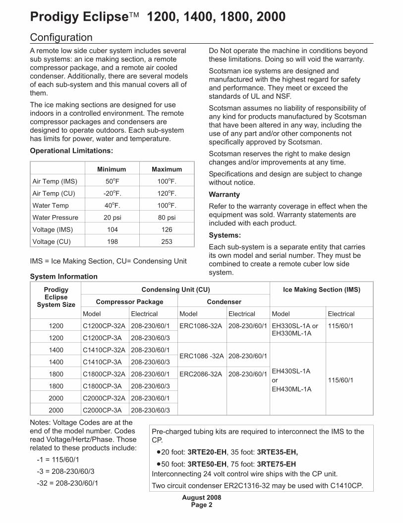
ConfigurationA remote low side cuber system includes severalsub systems: an ice making section, a remotecompressor package, and a remote air cooledcondenser. Additionally, there are several modelsof each sub-system and this manual covers all ofthem.
The ice making sections are designed for useindoors in a controlled environment. The remotecompressor packages and condensers aredesigned to operate outdoors. Each sub-systemhas limits for power, water and temperature.
Operational Limitations:
Minimum Maximum
Air Temp (IMS) 50oF 100
oF.
Air Temp (CU) -20oF. 120
oF.
Water Temp 40oF. 100
oF.
Water Pressure 20 psi 80 psi
Voltage (IMS) 104 126
Voltage (CU) 198 253
IMS = Ice Making Section, CU= Condensing Unit
Do Not operate the machine in conditions beyondthese limitations. Doing so will void the warranty.
Scotsman ice systems are designed andmanufactured with the highest regard for safetyand performance. They meet or exceed thestandards of UL and NSF.
Scotsman assumes no liability of responsibility ofany kind for products manufactured by Scotsmanthat have been altered in any way, including theuse of any part and/or other components notspecifically approved by Scotsman.
Scotsman reserves the right to make designchanges and/or improvements at any time.
Specifications and design are subject to changewithout notice.
Warranty
Refer to the warranty coverage in effect when theequipment was sold. Warranty statements areincluded with each product.
Systems:
Each sub-system is a separate entity that carriesits own model and serial number. They must becombined to create a remote cuber low sidesystem.
Prodigy Eclipse� 1200, 1400, 1800, 2000
August 2008Page 2
System Information
ProdigyEclipse
System Size
Condensing Unit (CU) Ice Making Section (IMS)
Compressor Package Condenser
Model Electrical Model Electrical Model Electrical
1200 C1200CP-32A 208-230/60/1 ERC1086-32A 208-230/60/1 EH330SL-1A orEH330ML-1A
115/60/1
1200 C1200CP-3A 208-230/60/3
1400 C1410CP-32A 208-230/60/1ERC1086 -32A 208-230/60/1
EH430SL-1A
or
EH430ML-1A
115/60/1
1400 C1410CP-3A 208-230/60/3
1800 C1800CP-32A 208-230/60/1 ERC2086-32A 208-230/60/1
1800 C1800CP-3A 208-230/60/3
2000 C2000CP-32A 208-230/60/1
2000 C2000CP-3A 208-230/60/3
Notes: Voltage Codes are at theend of the model number. Codesread Voltage/Hertz/Phase. Thoserelated to these products include:
-1 = 115/60/1
-3 = 208-230/60/3
-32 = 208-230/60/1
Pre-charged tubing kits are required to interconnect the IMS to theCP.
�20 foot: 3RTE20-EH, 35 foot: 3RTE35-EH,
�50 foot: 3RTE50-EH, 75 foot: 3RTE75-EH
Interconnecting 24 volt control wire ships with the CP unit.
Two circuit condenser ER2C1316-32 may be used with C1410CP.
Technical Specifications
Ice Making Section (IMS)
Compressor Package (CP)
Condenser
* * ERC condenser fan motor is powered from CPunit and the ERC’s ampacity is included in CP unitnumbers.
Model Number Description
Example:
�EH330SL-1A
�EH= Eclipse head
�3= Relative Size of Prodigy Eclipse head
�30= nominal width of cabinet.
�S= Cube size. S=small or half dice cube.M=medium or full dice cube
�L = Remote Low Side
�-1=Electrical code. -1=115 volts. -32=208-230single phase. -3=208-230 three phase. -6=23050 Hz
�A=Series revision code. A=first series
Note: In some areas of this manual modelnumbers may include only the first five charactersof the model number, meaning that the cube size,condenser type and voltage differences are notcritical to the information listed there.
Prodigy Eclipse� 1200, 1400, 1800, 2000
August 2008Page 3
Model Voltage Cube Size Minimum CircuitAmpacity
Max Fuse Size Cabinet Size Weight (lb)
EH330SL-1A 115/60/1 Small 3 15 30”w x 24”d x 23”h
EH330ML-1A 115/60/1 Medium 3 15 30”w x 24”d x 23”h
EH430SL-1A 115/60/1 Small 3 15 30”w x 24”d x 29”h 160
EH430ML-1A 115/60/1 Medium 3 15 30”w x 24”d x 29”h 160
Model Voltage ContainsHeadmaster?
MinimumCircuit
Ampacity
MaxFuseSize
RefrigerantCharge(R-404A)*
Cabinet Size Weight(lb)
C1200CP-32A 208-230/60/1 Yes 17.9 30 17 lb 29 ¾” w x 18”d x 34 ½” h 180
C1200CP-3A 208-230/60/3 Yes 14.2 20 17 lb same 180
C1410CP-32A 208-230/60/1 Yes 16.45 30 17 lb same 180
C1410CP-3A 208-230/60/3 Yes 12.58 20 17 lb same 180
C1800CP-32A 208-230/60/1 Yes 31.4 50 18 lb same 204
C1800CP-3A 208-230/60/3 Yes 19.0 30 18 lb same 204
C2000CP-32A 208-230/60/1 Yes 30.88 50 18 lb same 215
C2000CP-3A 208-230/60/3 Yes 21.0 30 18 lb same 215
* Includes entire system charge.
Model Voltage ContainsHeadmaster?
NumberofCircuits
MinimumCircuit
Ampacity**
MaxFuseSize**
Cabinet Size, with legs Weight(lb)
ERC1086-32A 208-230/60/1 No 1 1.25 15 29 ¾”w x 28 5/8”d x 38 ½”h 95
ERC2086-32A 208-230/60/1 No 1 1.25 15 29 ½” x 37 ¾” d x 38 ½” h 95
Model Number Locations
Ice Making Section
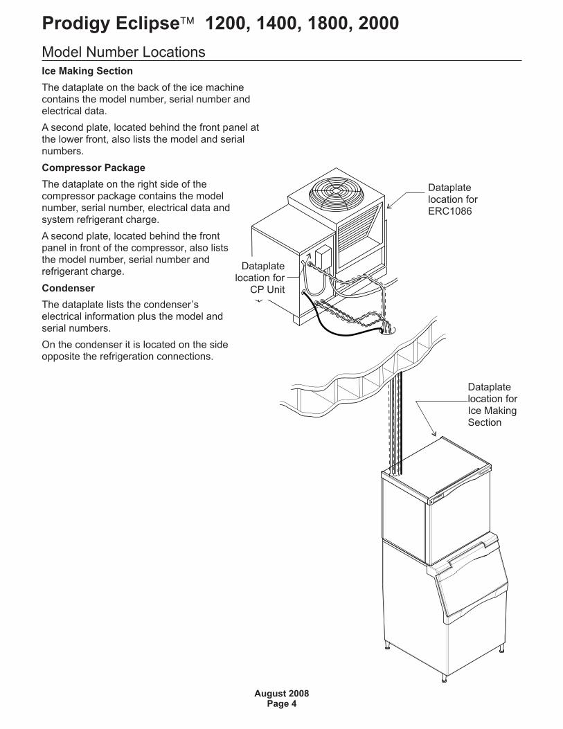
The dataplate on the back of the ice machinecontains the model number, serial number andelectrical data.
A second plate, located behind the front panel atthe lower front, also lists the model and serialnumbers.
Compressor Package
The dataplate on the right side of thecompressor package contains the modelnumber, serial number, electrical data andsystem refrigerant charge.
A second plate, located behind the frontpanel in front of the compressor, also liststhe model number, serial number andrefrigerant charge.
Condenser
The dataplate lists the condenser’selectrical information plus the model andserial numbers.
On the condenser it is located on the sideopposite the refrigeration connections.
Prodigy Eclipse� 1200, 1400, 1800, 2000
August 2008Page 4
Dataplatelocation for
CP Unit
Dataplatelocation forERC1086
Dataplatelocation forIce MakingSection
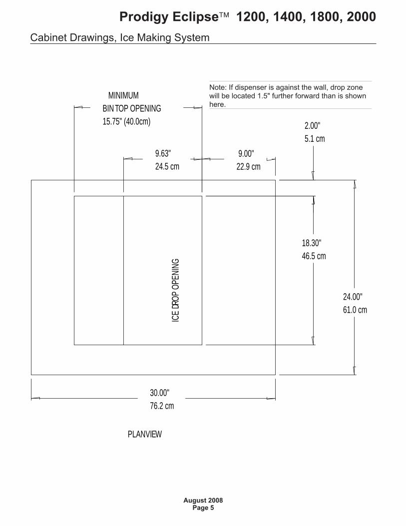
Cabinet Drawings, Ice Making System
Prodigy Eclipse� 1200, 1400, 1800, 2000
August 2008Page 5
30.00"76.2 cm
24.00"61.0 cm
ICE D
ROP O
PENI
NG
9.00"22.9 cm
9.63"24.5 cm
MINIMUM BIN TOP OPENING15.75" (40.0cm) 2.00"
5.1 cm
18.30"46.5 cm
PLAN VIEW
Note: If dispenser is against the wall, drop zonewill be located 1.5" further forward than is shownhere.
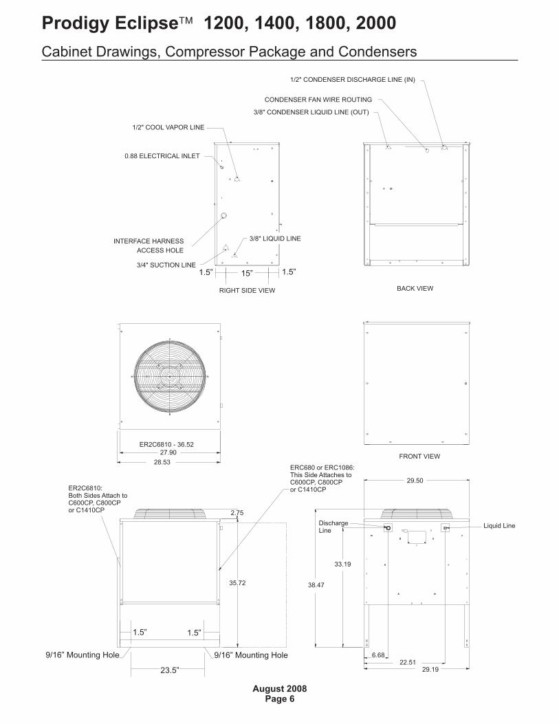
Cabinet Drawings, Compressor Package and Condensers
Prodigy Eclipse� 1200, 1400, 1800, 2000
August 2008Page 6
BACK VIEW
FRONT VIEW
RIGHT SIDE VIEW
1/2" COOL VAPOR LINE
0.88 ELECTRICAL INLET
3/4" SUCTION LINE
INTERFACE HARNESS
ACCESS HOLE
3/8" CONDENSER LIQUID LINE (OUT)
1/2" CONDENSER DISCHARGE LINE (IN)
CONDENSER FAN WIRE ROUTING
ERC680 or ERC1086:This Side Attaches toC600CP, C800CPor C1410CPER2C6810:
Both Sides Attach toC600CP, C800CPor C1410CP
27.90
28.53
35.72
2.75
Liquid LineDischargeLine
29.50
38.47
33.19
6.6822.51
29.19
ER2C6810 - 36.52
9/16” Mounting Hole 9/16” Mounting Hole
23.5”
1.5” 1.5”
3/8" LIQUID LINE
15”1.5” 1.5”
Proper Combinations:The three sub systems are designed to beconnected together in certain combinations tomeet the user’s needs:
Eclipse 1200 System
�EH330, C1200CP, ERC1086
Eclipse 1400 System:
�EH430, C1410CP, ERC1086
Eclipse 1800 System:
�EH430, C1800CP, ERC2086
Eclipse 2000 System:
�EH430, C2000CP, ERC2086
ERC coils may be substituted for by an approvedUL listed central condenser coil & fan (coil must bewithout headmaster - headmaster is part of CP).
ERC1086 condenser coil internal volume target is165 cubic inches, BHTU target is 42,000 BTUH.
ERC2086 condenser coil internal volume target is209 cubic inches, BTUH target is 48,000 BTUH
Note: The ice making section cannot be stackedvertically.
Accessories such as bin adapters and tubing kitsare required to complete the installation.
Dispenser Adapter Kits:
�Scotsman ID200 or ID250: KBT44
Bin Adapter Kits:
�B842: KBT29
�B948: KBT22
Tubing Kits:
�20 foot: 3RTE20-EH
�35 foot: 3RTE35-EH
�50 foot: 3RTE50-EH
�75 foot: 3RTE75-EH
�Suction Line Trap: KSLT075
�Interconnecting Tubing to Approved RackCondenser Coil: RTE10
�Line end kit: KTE6-EH
Items required for installation:
�Ice making section
�Compressor Package (includes interconnectingcontrol system wire)
�Remote condenser or approved rack coilw/tubing kit
�20’, 35’, 50’ or 75’ triple line set (liquid, vaporand suction)
�Bin or dispenser adapter
Special Considerations
The ice making section’s footprint is 30” wide by24” deep. The refrigeration connections can bemade out the top panel or out the back. Theelectrical power cord and the water inlet line canalso be routed through either of those areas. Thedrain may be routed out the back or to the left side.
Water
Pure water does not exist. All water suppliescontain some amounts of impurities, althoughpotable water is, by definition, fit for humanconsumption. Because the contents of the water toan ice machine directly impact its performance,consideration should be given to improving thewater’s quality.
There are two ways water can contain impurities:in suspension or in solution. Suspended solids canbe filtered out of the water. In solution or dissolvedsolids must be diluted or treated. Water filters arerecommended to remove the suspended solids.Some filters or filter systems have treatmentchemicals in them for treating the suspendedsolids.
This ice machine has an adjustment for theamount of water rinsed or purged. Water useadjustments are customer convenienceadjustments; they are not factory defects and arenot covered by warranty.
Prodigy Eclipse� 1200, 1400, 1800, 2000
August 2008Page 7
Create the System
Plan the installation. The system consists of fourparts: the ice making section, the compressorpackage, the interconnecting tubing and theremote condenser. Of these, the biggest variable isthe interconnecting tubing.
Tubing: The tubing consists of three pre-charged,insulated and sealed soft copper tubes. They eachcontain a small holding charge of R-404A. Onetube, the liquid line, is 3/8” OD. The vapor tube is½” OD and the suction tube is ¾” OD. A siteinspection will determine what length of tubing isrequired for the installation.
Excess tubing must be either shortened at the jobsite (recovering the holding charge, purging withnitrogen when brazing and evacuating to 50microns) or coiled up inside the building.
Installations with greater than 20 feet of vertical liftbetween ice machine and the compressor requirea suction line trap. The suction line requires carefulhandling and large radius bends to prevent kinking.
Roof mounting: To make installation easier thecompressor and condenser are designed to beassembled together on the roof. Someinstallations will require the use of a hoist to lift thecomponents to the roof.
Pad mounting: The compressor and condensermay be located below the ice making section, up toa limit of 15 feet.
Distance from unit: Limited to the length of theavailable pre-charged tubing.
Elevation: CP unit limited to 35 feet above the icemaking section.
Compressor package: Electrical power must besupplied to the compressor package. The remotecondenser fan motor takes its power from thecompressor package.
Ice making section location and attachment:The 115/60 Hz ice making section is cordconnected and requires an outlet within 6 feet ofthe installation.
Interconnecting wires: An interconnecting wireharness is included with the CP unit. One endplugs into the ice making section and the other intothe compressor package. The system will NOToperate without this harness.
Exposed tubing: Minimize the amount of tubingexposed outdoors.
Confirm Component Availability:
EH330
�C1200CP with ERC1086
EH430
�C1410CP with ERC1086 or
�C1800CP with ERC2086 or
�C2000CP with ERC2086
�ERC required unless connecting to an approvedcondenser coil.
Note: Only these condensers may be used. Theydo NOT contain a headmaster valve. That valve is
in the Compressor Package. Do NOT use any
other Scotsman condenser. Do NOT use thesecondensers on any other Scotsman remoteproduct.
�Interconnecting tubing kit
Note: Check tubing integrity before assembly byattaching a refrigeration compound gauge ontoone of each tube’s schrader valves. If there ispressure, the tube is OK, if not it should bechecked for damage and leaks.
�Bin or dispenser adapter
Prodigy Eclipse� 1200, 1400, 1800, 2000
August 2008Page 8
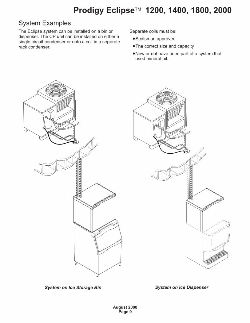
System ExamplesThe Eclipse system can be installed on a bin ordispenser. The CP unit can be installed on either asingle circuit condenser or onto a coil in a separaterack condenser.
Separate coils must be:
�Scotsman approved
�The correct size and capacity
�New or not have been part of a system thatused mineral oil.
Prodigy Eclipse� 1200, 1400, 1800, 2000
August 2008Page 9
System on Ice Storage Bin System on Ice Dispenser
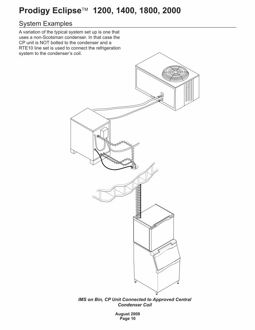
System ExamplesA variation of the typical system set up is one thatuses a non-Scotsman condenser. In that case theCP unit is NOT bolted to the condenser and aRTE10 line set is used to connect the refrigerationsystem to the condenser’s coil.
Prodigy Eclipse� 1200, 1400, 1800, 2000
August 2008Page 10
IMS on Bin, CP Unit Connected to Approved CentralCondenser Coil
Place Remote SystemRoof preparation
Most installations of this system will place thecompressor package and condenser on the roof ofa building. The roof must be physically stoutenough to accept the load of the equipment andthe roofing material must be prepared to preventwater leaks.
Follow local codes for the placement andattachment of the equipment.
Location
The air cooled condensing unit assembly requiresunobstructed air flow to operate efficiently. A fourfoot space between each intake side and a wall orother cabinet is recommended. Provide at least 2feet of space above the air cooled condenser forproper air flow.
Do not place where the air cooled condenser willpick up hot discharged air from an air conditioneror other refrigeration system condensing unit.
Space must also be reserved for service on thecompressor package.
Roof Piercing:
The roof (or wall) must have a passage largeenough for the three pre-charged, pre-bent tubesand the control wire to pass through. The minimumrecommended size is 4” ID. In most areas thepower supply may also pass through the samepassage. If there isn’t a passage one must becreated. In most cases this must be done by alicensed and bonded roofer in order to maintain theroof’s integrity.
Suggestions:
Hoist the compressor package and condenser tothe roof in separate loads.
Note: In most cases a mechanical lift, boom truckor crane will be required to hoist the condensingunit components.
Assemble the compressor package to thecondenser and mount both to either roof rails orpressure treated 4 x 4s.
Orient the assembled unit so that the unit’s mountsare parallel to the pitch of the roof to allow water todrain freely.
Do NOT place the unit directly onto roof rock.
Prodigy Eclipse� 1200, 1400, 1800, 2000
August 2008Page 11
System Location
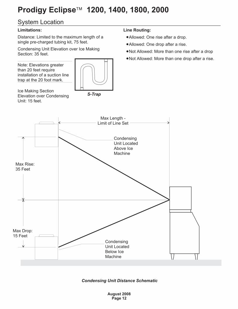
Limitations:
Distance: Limited to the maximum length of asingle pre-charged tubing kit, 75 feet.
Condensing Unit Elevation over Ice MakingSection: 35 feet.
Note: Elevations greaterthan 20 feet requireinstallation of a suction linetrap at the 20 foot mark.
Ice Making SectionElevation over CondensingUnit: 15 feet.
Line Routing:
�Allowed: One rise after a drop.
�Allowed: One drop after a rise.
�Not Allowed: More than one rise after a drop
�Not Allowed: More than one drop after a rise.
Prodigy Eclipse� 1200, 1400, 1800, 2000
August 2008Page 12
22
.87
"1
7.1
5"
40.35"
Condensing Unit Distance Schematic
Max Rise:35 Feet
Max Drop:15 Feet
Max Length -Limit of Line Set
CondensingUnit LocatedBelow IceMachine
CondensingUnit LocatedAbove IceMachine
S-Trap
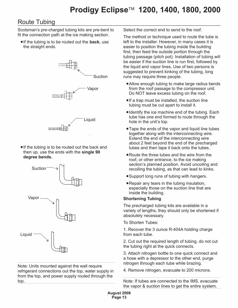
Route TubingScotsman’s pre-charged tubing kits are pre-bent tofit the connection path at the ice making section.
�If the tubing is to be routed out the back, usethe straight ends.
�If the tubing is to be routed out the back andthen up, use the ends with the single 90degree bends.
Note: Units mounted against the wall requirerefrigerant connections out the top, water supply infrom the top, and power supply routed through thetop.
Select the correct end to send to the roof.
The method or technique used to route the tube isleft to the installer. However, in many cases it iseasier to position the tubing inside the buildingfirst, then feed the outside portion through thetubing passage (pitch pot). Installation of tubing willbe easier if the suction line is run first, followed bythe liquid and vapor lines. Use of two persons issuggested to prevent kinking of the tubing, longruns may require three people.
�Allow enough tubing to make large radius bendsfrom the roof passage to the compressor unit.Do NOT leave excess tubing on the roof.
�If a trap must be installed, the suction linetubing must be cut apart to install it.
�Identify the ice machine end of the tubing. Eachtube has one end formed to route through thehole in the unit’s top.
�Tape the ends of the vapor and liquid line tubestogether along with the interconnecting wire.Extend the end of the interconnecting wireabout 2 feet beyond the end of the prechargedtubes and then tape it back onto the tubes.
�Route the three tubes and the wire from theroof, or other entrance, to the ice makingsection’s planned position. Avoid uncoiling andrecoiling the tubing, as that can lead to kinks.
�Support long runs of tubing with hangers.
�Repair any tears in the tubing insulation,especially those on the suction line that areinside the building.
Shortening Tubing
The precharged tubing kits are available in avariety of lengths, they should only be shortened ifabsolutely necessary.
To Shorten Tubes:
1. Recover the 3 ounce R-404A holding chargefrom each tube.
2. Cut out the required length of tubing, do not cutthe tubing right at the quick connects.
3. Attach nitrogen bottle to one quick connect anda hose with a depressor to the other end, purgenitrogen through each tube while brazing.
4. Remove nitrogen, evacuate to 200 microns.
Note: If tubes are connected to the IMS, evacuatethe vapor & suction lines to get the entire system.
Prodigy Eclipse� 1200, 1400, 1800, 2000
August 2008Page 13
Suction
Vapor
Liquid
Suction
Vapor
Liquid
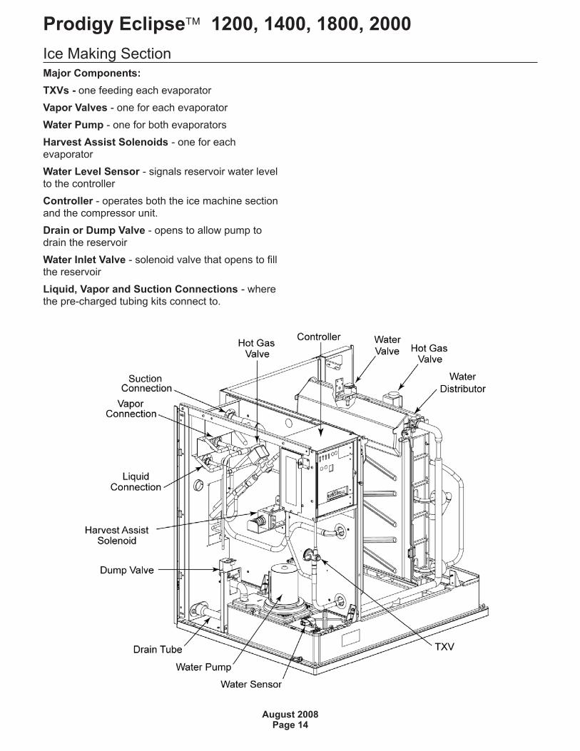
Ice Making Section
Major Components:
TXVs - one feeding each evaporator
Vapor Valves - one for each evaporator
Water Pump - one for both evaporators
Harvest Assist Solenoids - one for eachevaporator
Water Level Sensor - signals reservoir water levelto the controller
Controller - operates both the ice machine sectionand the compressor unit.
Drain or Dump Valve - opens to allow pump todrain the reservoir
Water Inlet Valve - solenoid valve that opens to fillthe reservoir
Liquid, Vapor and Suction Connections - wherethe pre-charged tubing kits connect to.
Prodigy Eclipse� 1200, 1400, 1800, 2000
August 2008Page 14
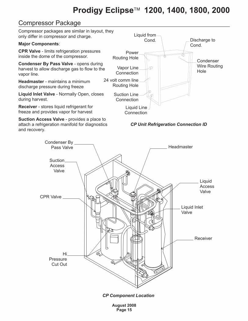
Compressor PackageCompressor packages are similar in layout, they
only differ in compressor and charge.
Major Components:
CPR Valve - limits refrigeration pressuresinside the dome of the compressor.
Condenser By Pass Valve - opens duringharvest to allow discharge gas to flow to thevapor line.
Headmaster - maintains a minimumdischarge pressure during freeze
Liquid Inlet Valve - Normally Open, closesduring harvest.
Receiver - stores liquid refrigerant forfreeze and provides vapor for harvest
Suction Access Valve - provides a place toattach a refrigeration manifold for diagnosticsand recovery.
Prodigy Eclipse� 1200, 1400, 1800, 2000
August 2008Page 15
CP Unit Refrigeration Connection ID
PowerRouting Hole
Vapor LineConnection
24 volt comm lineRouting Hole
Liquid LineConnection
Suction LineConnection
Liquid fromCond. Discharge to
Cond.
CondenserWire RoutingHole
CP Component Location
CPR Valve
LiquidAccessValve
HeadmasterCondenser By
Pass Valve
HiPressure
Cut Out
Liquid InletValve
Receiver
SuctionAccess
Valve
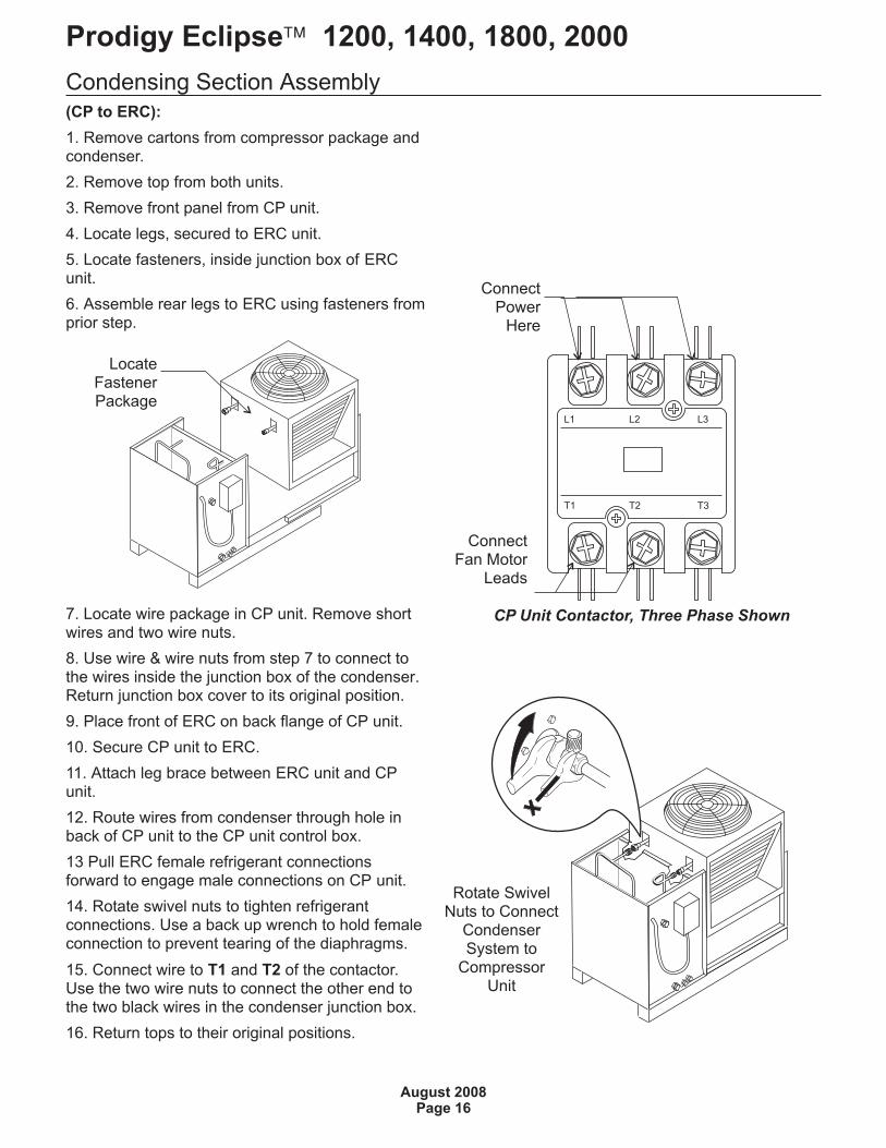
Condensing Section Assembly
(CP to ERC):
1. Remove cartons from compressor package andcondenser.
2. Remove top from both units.
3. Remove front panel from CP unit.
4. Locate legs, secured to ERC unit.
5. Locate fasteners, inside junction box of ERCunit.
6. Assemble rear legs to ERC using fasteners fromprior step.
7. Locate wire package in CP unit. Remove shortwires and two wire nuts.
8. Use wire & wire nuts from step 7 to connect tothe wires inside the junction box of the condenser.Return junction box cover to its original position.
9. Place front of ERC on back flange of CP unit.
10. Secure CP unit to ERC.
11. Attach leg brace between ERC unit and CPunit.
12. Route wires from condenser through hole inback of CP unit to the CP unit control box.
13 Pull ERC female refrigerant connectionsforward to engage male connections on CP unit.
14. Rotate swivel nuts to tighten refrigerantconnections. Use a back up wrench to hold femaleconnection to prevent tearing of the diaphragms.
15. Connect wire to T1 and T2 of the contactor.Use the two wire nuts to connect the other end tothe two black wires in the condenser junction box.
16. Return tops to their original positions.
Prodigy Eclipse� 1200, 1400, 1800, 2000
August 2008Page 16
CP Unit Contactor, Three Phase Shown
ConnectFan Motor
Leads
ConnectPower
Here
Rotate SwivelNuts to Connect
CondenserSystem to
CompressorUnit
LocateFastenerPackage
Condensing Section Assembly
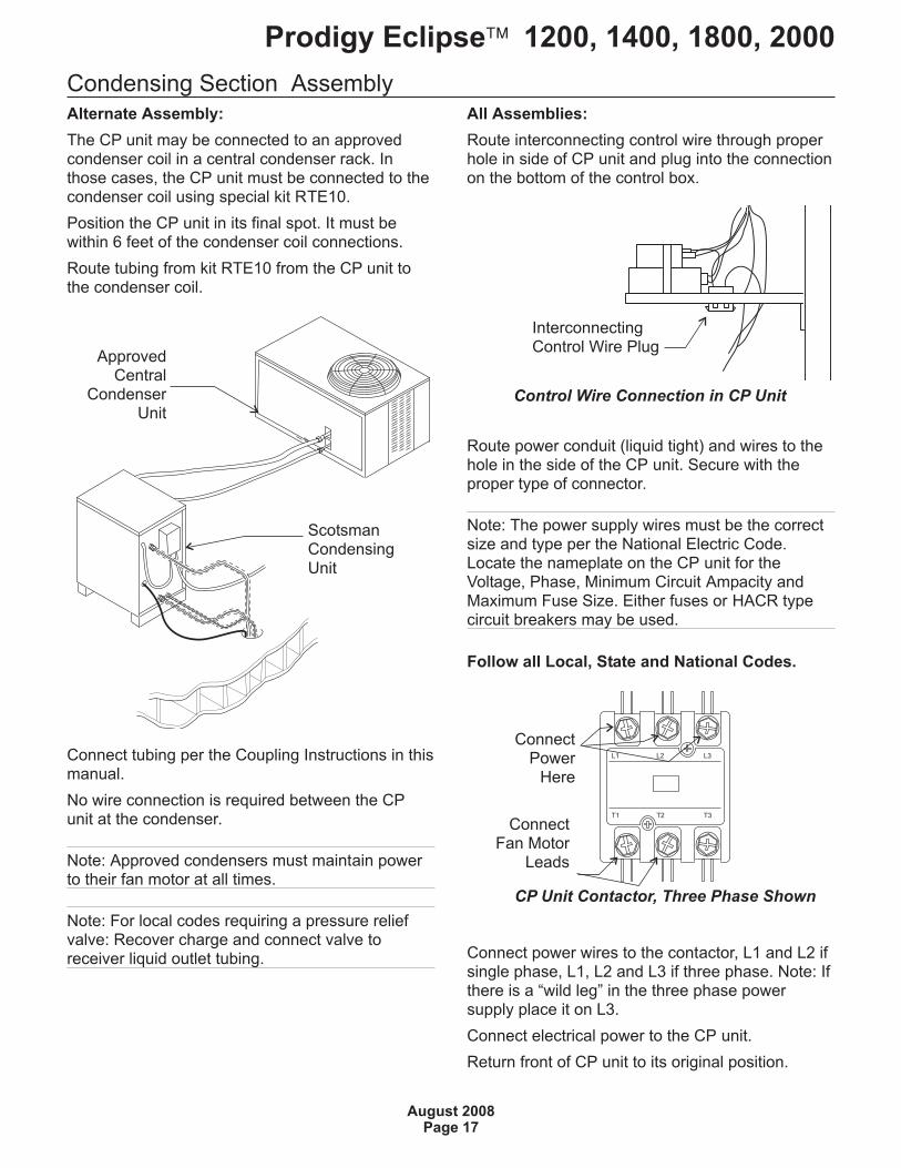
Alternate Assembly:
The CP unit may be connected to an approvedcondenser coil in a central condenser rack. Inthose cases, the CP unit must be connected to thecondenser coil using special kit RTE10.
Position the CP unit in its final spot. It must bewithin 6 feet of the condenser coil connections.
Route tubing from kit RTE10 from the CP unit tothe condenser coil.
Connect tubing per the Coupling Instructions in thismanual.
No wire connection is required between the CPunit at the condenser.
Note: Approved condensers must maintain powerto their fan motor at all times.
Note: For local codes requiring a pressure reliefvalve: Recover charge and connect valve toreceiver liquid outlet tubing.
All Assemblies:
Route interconnecting control wire through properhole in side of CP unit and plug into the connectionon the bottom of the control box.
Route power conduit (liquid tight) and wires to thehole in the side of the CP unit. Secure with theproper type of connector.
Note: The power supply wires must be the correctsize and type per the National Electric Code.Locate the nameplate on the CP unit for theVoltage, Phase, Minimum Circuit Ampacity andMaximum Fuse Size. Either fuses or HACR typecircuit breakers may be used.
Follow all Local, State and National Codes.
Connect power wires to the contactor, L1 and L2 ifsingle phase, L1, L2 and L3 if three phase. Note: Ifthere is a “wild leg” in the three phase powersupply place it on L3.
Connect electrical power to the CP unit.
Return front of CP unit to its original position.
Prodigy Eclipse� 1200, 1400, 1800, 2000
August 2008Page 17
Control Wire Connection in CP Unit
InterconnectingControl Wire Plug
CP Unit Contactor, Three Phase Shown
ConnectPower
Here
ConnectFan Motor
Leads
ApprovedCentral
CondenserUnit
ScotsmanCondensingUnit
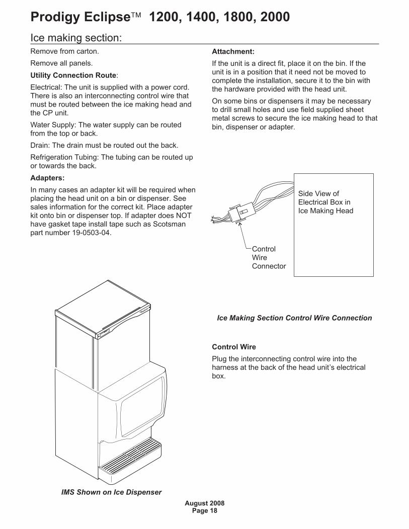
Ice making section:Remove from carton.
Remove all panels.
Utility Connection Route:
Electrical: The unit is supplied with a power cord.There is also an interconnecting control wire thatmust be routed between the ice making head andthe CP unit.
Water Supply: The water supply can be routedfrom the top or back.
Drain: The drain must be routed out the back.
Refrigeration Tubing: The tubing can be routed upor towards the back.
Adapters:
In many cases an adapter kit will be required whenplacing the head unit on a bin or dispenser. Seesales information for the correct kit. Place adapterkit onto bin or dispenser top. If adapter does NOThave gasket tape install tape such as Scotsmanpart number 19-0503-04.
Attachment:
If the unit is a direct fit, place it on the bin. If theunit is in a position that it need not be moved tocomplete the installation, secure it to the bin withthe hardware provided with the head unit.
On some bins or dispensers it may be necessaryto drill small holes and use field supplied sheetmetal screws to secure the ice making head to that
bin, dispenser or adapter.
Control Wire
Plug the interconnecting control wire into theharness at the back of the head unit’s electricalbox.
Prodigy Eclipse� 1200, 1400, 1800, 2000
August 2008Page 18
Ice Making Section Control Wire Connection
IMS Shown on Ice Dispenser
ControlWireConnector
Side View ofElectrical Box inIce Making Head
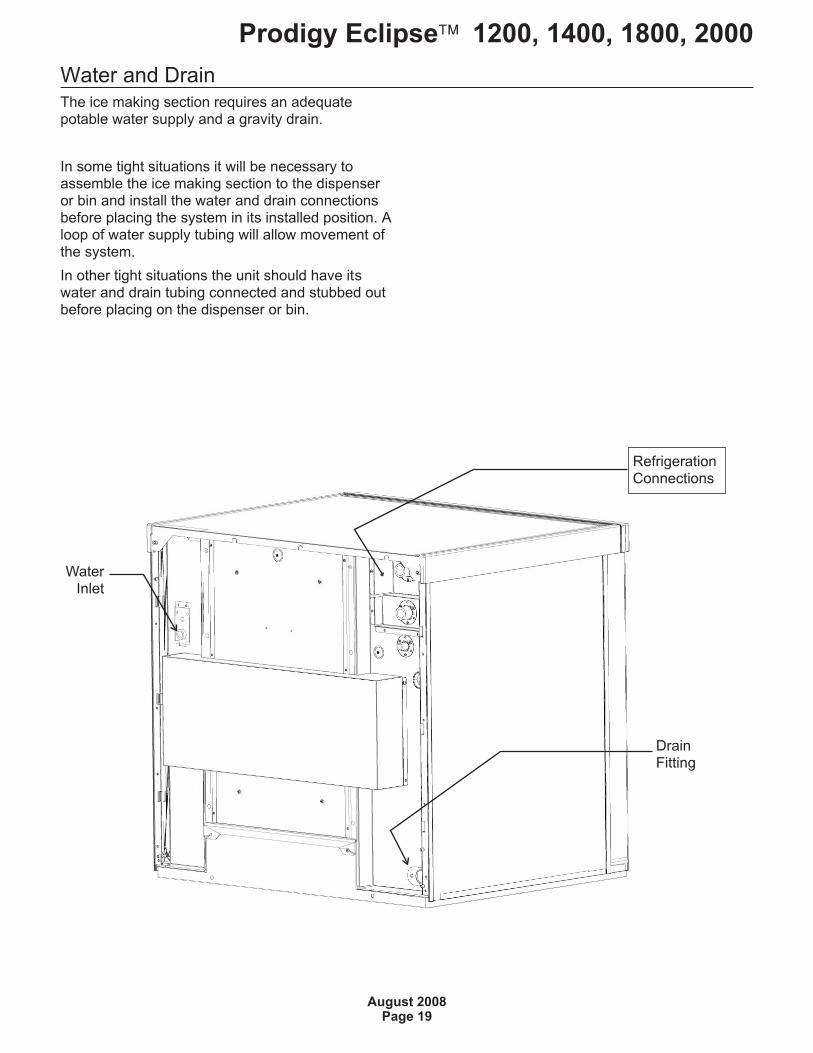
Water and DrainThe ice making section requires an adequatepotable water supply and a gravity drain.
In some tight situations it will be necessary toassemble the ice making section to the dispenseror bin and install the water and drain connectionsbefore placing the system in its installed position. Aloop of water supply tubing will allow movement ofthe system.
In other tight situations the unit should have itswater and drain tubing connected and stubbed outbefore placing on the dispenser or bin.
Prodigy Eclipse� 1200, 1400, 1800, 2000
August 2008Page 19
DrainFitting
WaterInlet
RefrigerationConnections
Water and Drain
All models require connection to cold, potablewater. A hand actuated valve within site of themachine is required. There is a single 3/8” FPTinlet water connection, a 3/8” FPT to 3/8” maleflare adapter is supplied with the machine and canbe used if desired.
Water Filters
Install a new cartridge if the filters were used with aprior machine.
All models require drain tubing to be attached tothem. There is a single ¾” FPT drain fitting in theback of the cabinet.
Install new tubing when replacing a prior icemachine, as the tubing will have been sized for theold model and might not be correct for this one.
1. Connect water supply to water inlet fitting.
Note: This NSF listed model has a 1" anti-backflow air gap between the potable water inlet tubeend and the highest possible reservoir water level,no back flow device is required.
2. Connect drain tubing to drain fitting.
3. Route the drain tubing to building drain. Followlocal codes for drain air gap.
Use rigid drain tubes and route them separately –do not Tee into the bin’s drain.
Vent the reservoir drain. A vertical vent at the backof the drain, extended about 8 – 10” will allow thegravity drain to empty and also keep any surgesduring draining from discharging water.
Horizontal runs of drain tubing need a ¼” per fallper foot of run for proper draining.
Follow all applicable codes.
Prodigy Eclipse� 1200, 1400, 1800, 2000
August 2008Page 20
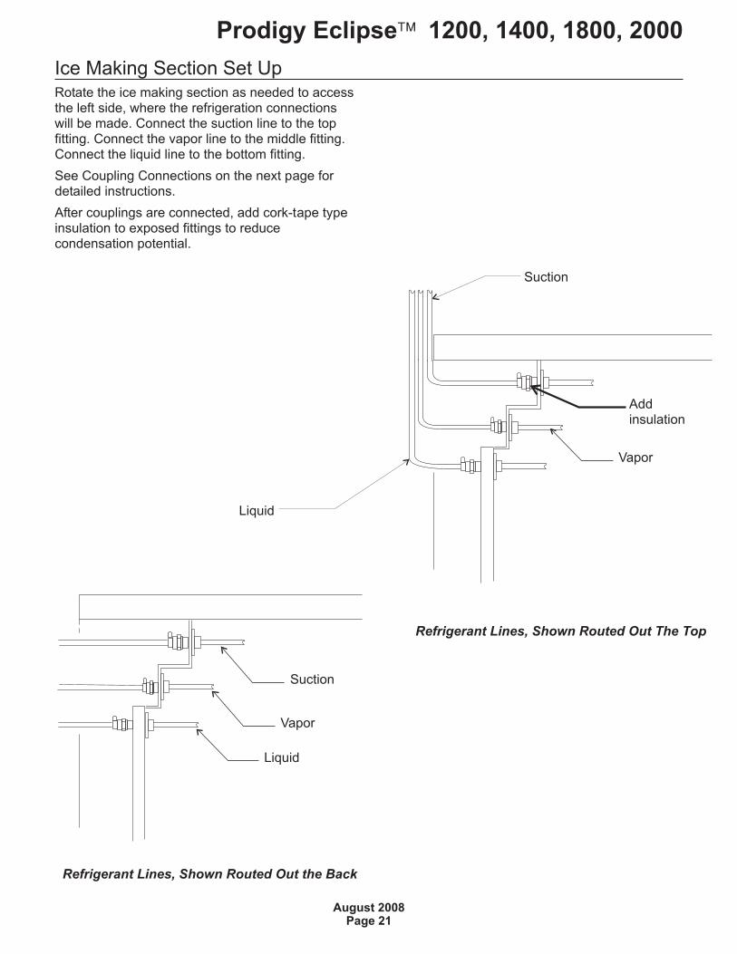
Ice Making Section Set UpRotate the ice making section as needed to accessthe left side, where the refrigeration connectionswill be made. Connect the suction line to the topfitting. Connect the vapor line to the middle fitting.Connect the liquid line to the bottom fitting.
See Coupling Connections on the next page fordetailed instructions.
After couplings are connected, add cork-tape typeinsulation to exposed fittings to reducecondensation potential.
Prodigy Eclipse� 1200, 1400, 1800, 2000
August 2008Page 21
Refrigerant Lines, Shown Routed Out The Top
Addinsulation
Suction
Vapor
Liquid
Refrigerant Lines, Shown Routed Out the Back
Vapor
Liquid
Suction
Coupling Connections:The couplings on the ends of the pre-charged linesets are self-sealing when installed properly.
Follow these instructions carefully. These stepsmust be performed by an EPA Certified Type II orhigher technician.
Initial Connections
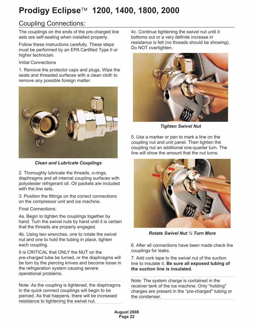
1. Remove the protector caps and plugs. Wipe theseats and threaded surfaces with a clean cloth toremove any possible foreign matter.
2. Thoroughly lubricate the threads, o-rings,diaphragms and all internal coupling surfaces withpolyolester refrigerant oil. Oil packets are includedwith the line sets.
3. Position the fittings on the correct connectionson the compressor unit and ice machine.
Final Connections:
4a. Begin to tighten the couplings together byhand. Turn the swivel nuts by hand until it is certainthat the threads are properly engaged.
4b. Using two wrenches, one to rotate the swivelnut and one to hold the tubing in place, tighteneach coupling.
It is CRITICAL that ONLY the NUT on thepre-charged tube be turned, or the diaphragms willbe torn by the piercing knives and become loose inthe refrigeration system causing severeoperational problems.
Note: As the coupling is tightened, the diaphragmsin the quick connect couplings will begin to bepierced. As that happens, there will be increasedresistance to tightening the swivel nut.
4c. Continue tightening the swivel nut until itbottoms out or a very definite increase inresistance is felt (no threads should be showing).Do NOT overtighten.
5. Use a marker or pen to mark a line on thecoupling nut and unit panel. Then tighten thecoupling nut an additional one-quarter turn. Theline will show the amount that the nut turns.
6. After all connections have been made check thecouplings for leaks.
7. Add cork tape to the swivel nut of the suction
line to insulate it. Be sure all exposed tubing of
the suction line is insulated.
Note: The system charge is contained in thereceiver tank of the ice machine. Only “holding"charges are present in the “pre-charged" tubing orthe condenser.
Prodigy Eclipse� 1200, 1400, 1800, 2000
August 2008Page 22
Clean and Lubricate Couplings
Tighten Swivel Nut
Rotate Swivel Nut ¼ Turn More
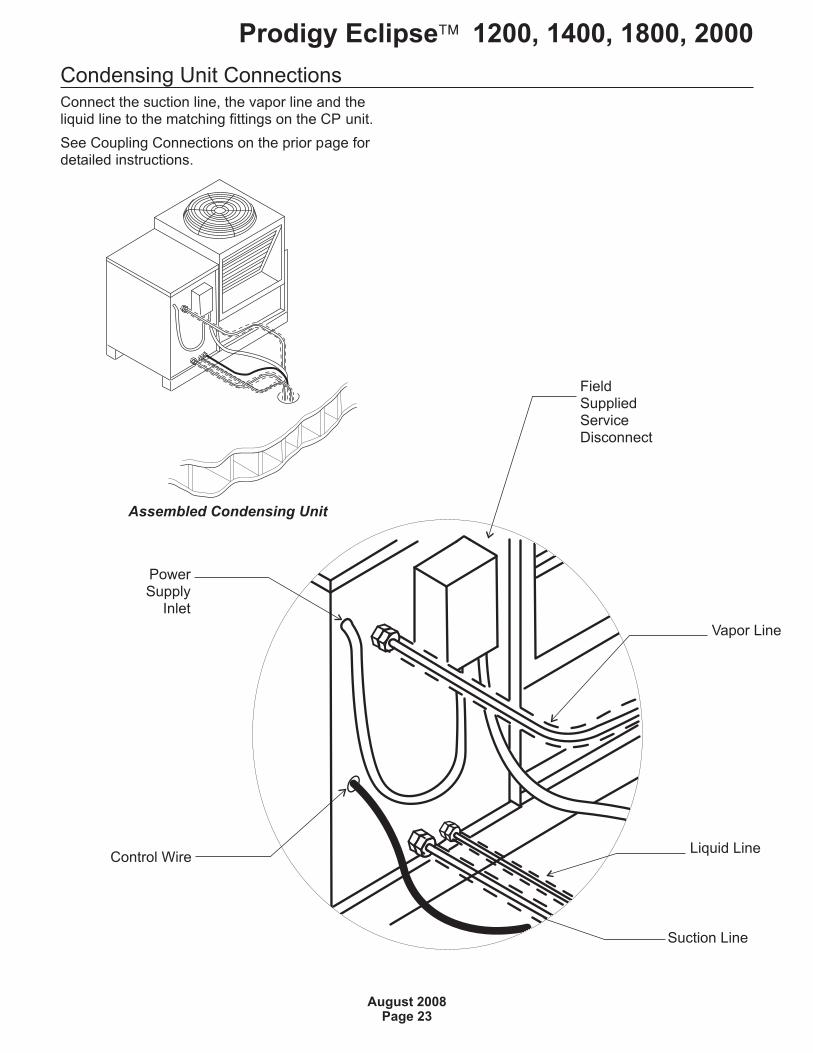
Condensing Unit ConnectionsConnect the suction line, the vapor line and theliquid line to the matching fittings on the CP unit.
See Coupling Connections on the prior page fordetailed instructions.
Prodigy Eclipse� 1200, 1400, 1800, 2000
August 2008Page 23
Assembled Condensing Unit
Control Wire
PowerSupply
Inlet
FieldSuppliedServiceDisconnect
Liquid Line
Suction Line
Vapor Line
Final PlacementAfter the utilities and refrigeration connectionshave been made, secure the unit to the dispenseror bin top.
Secure ice making section to dispenser or binadapter.
Use strap/clips to secure unit. On some bins ordispensers it may be necessary to drill small holesand use field supplied sheet metal screws tosecure the ice making head to that bin, dispenser
or adapter.
If the ice maker & bin or dispenser is not yet in itsfinal position gently move it there.
Note: The refrigerant lines above the machinemust be able to move freely while the machine isbeing moved into position.
Final Check List Before Initial Start Up
1. Confirm that the ice making section is installedindoors in a controlled environment.
2. Confirm that all packing materials have beenremoved from all products.
3. Confirm that the ice making section is level.
4. Confirm that all the refrigerant connectionshave been made and checked for leaks.
5. Confirm that the proper power supply has beenturned on to the condensing unit.
6. Confirm that cold, potable water has beensupplied to the ice making section and checkedfor leaks.
7. Confirm that the water supply is adequate.
8. Confirm that there is adequate water pressureand that any water filters have been checked toconfirm that the cartridges do not needchanging.
9. Confirm that the proper size drain tubing hasbeen installed and properly routed.
10. Confirm that the ice making section has beenconnected to the proper power supply.
11. Confirm that the interconnecting wire has beenrouted and connected between the ice makingsection and the compressor package.
Prodigy Eclipse� 1200, 1400, 1800, 2000
August 2008Page 24
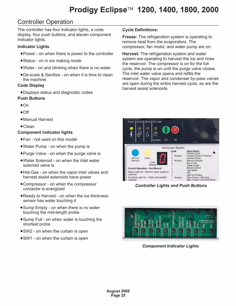
Controller OperationThe controller has four indicator lights, a codedisplay, four push buttons, and eleven componentindicator lights.
Indicator Lights
�Power - on when there is power to the controller
�Status - on in ice making mode
�Water - on and blinking when there is no water
�De-scale & Sanitize - on when it is time to cleanthe machine
Code Display
�Displays status and diagnostic codes
Push Buttons
�On
�Off
�Manual Harvest
�Clean
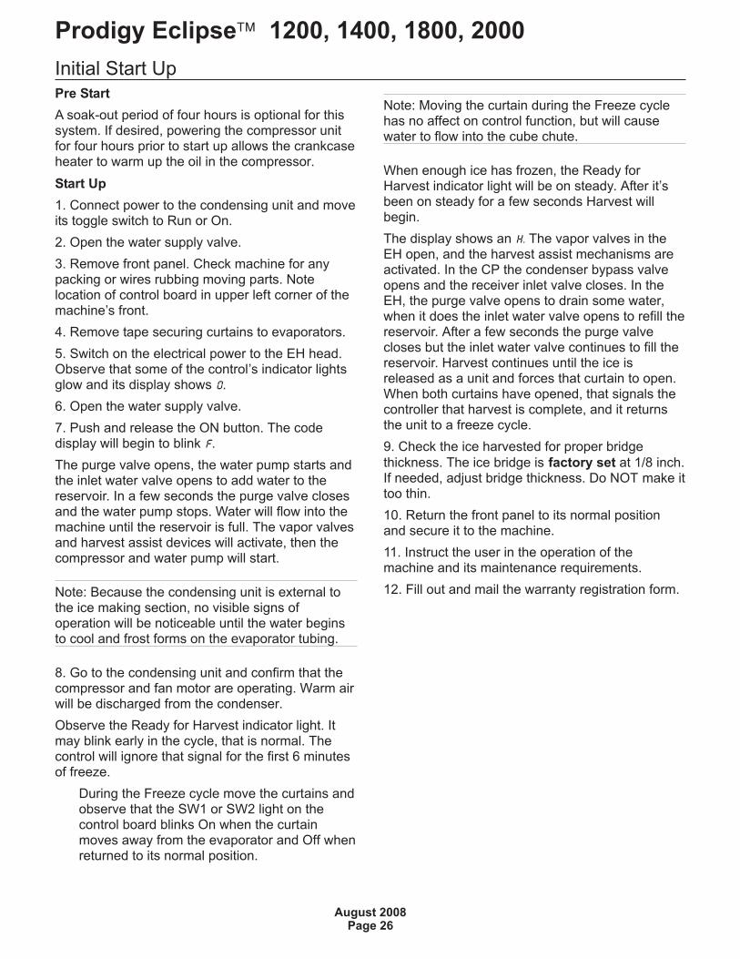
Component indicator lights
�Fan - not used on this model
�Water Pump - on when the pump is
�Purge Valve - on when the purge valve is
�Water Solenoid - on when the inlet watersolenoid valve is
�Hot Gas - on when the vapor inlet valves andharvest assist solenoids have power
�Compressor - on when the compressorcontactor is energized
�Ready to Harvest - on when the ice thicknesssensor has water touching it
�Sump Empty - on when there is no watertouching the mid-length probe
�Sump Full - on when water is touching theshortest probe
�SW2 - on when the curtain is open
�SW1 - on when the curtain is open
Cycle Definitions:
Freeze: The refrigeration system is operating toremove heat from the evaporators. Thecompressor, fan motor, and water pump are on.
Harvest: The refrigeration system and watersystem are operating to harvest the ice and rinsethe reservoir. The compressor is on for the fullcycle, the pump is on until the purge valve closes.The inlet water valve opens and refills thereservoir. The vapor and condenser by-pass valvesare open during the entire harvest cycle, as are theharvest assist solenoids.
Prodigy Eclipse� 1200, 1400, 1800, 2000
August 2008Page 25
Controller Lights and Push Buttons
Component Indicator Lights
Initial Start Up
Pre Start
A soak-out period of four hours is optional for thissystem. If desired, powering the compressor unitfor four hours prior to start up allows the crankcaseheater to warm up the oil in the compressor.
Start Up
1. Connect power to the condensing unit and moveits toggle switch to Run or On.
2. Open the water supply valve.
3. Remove front panel. Check machine for anypacking or wires rubbing moving parts. Notelocation of control board in upper left corner of themachine’s front.
4. Remove tape securing curtains to evaporators.
5. Switch on the electrical power to the EH head.Observe that some of the control’s indicator lightsglow and its display shows O.
6. Open the water supply valve.
7. Push and release the ON button. The codedisplay will begin to blink F.
The purge valve opens, the water pump starts andthe inlet water valve opens to add water to thereservoir. In a few seconds the purge valve closesand the water pump stops. Water will flow into themachine until the reservoir is full. The vapor valvesand harvest assist devices will activate, then thecompressor and water pump will start.
Note: Because the condensing unit is external tothe ice making section, no visible signs ofoperation will be noticeable until the water beginsto cool and frost forms on the evaporator tubing.
8. Go to the condensing unit and confirm that thecompressor and fan motor are operating. Warm airwill be discharged from the condenser.
Observe the Ready for Harvest indicator light. Itmay blink early in the cycle, that is normal. Thecontrol will ignore that signal for the first 6 minutesof freeze.
During the Freeze cycle move the curtains andobserve that the SW1 or SW2 light on thecontrol board blinks On when the curtainmoves away from the evaporator and Off whenreturned to its normal position.
Note: Moving the curtain during the Freeze cyclehas no affect on control function, but will causewater to flow into the cube chute.
When enough ice has frozen, the Ready forHarvest indicator light will be on steady. After it’sbeen on steady for a few seconds Harvest willbegin.
The display shows an H. The vapor valves in theEH open, and the harvest assist mechanisms areactivated. In the CP the condenser bypass valveopens and the receiver inlet valve closes. In theEH, the purge valve opens to drain some water,when it does the inlet water valve opens to refill thereservoir. After a few seconds the purge valvecloses but the inlet water valve continues to fill thereservoir. Harvest continues until the ice isreleased as a unit and forces that curtain to open.When both curtains have opened, that signals thecontroller that harvest is complete, and it returnsthe unit to a freeze cycle.
9. Check the ice harvested for proper bridge
thickness. The ice bridge is factory set at 1/8 inch.If needed, adjust bridge thickness. Do NOT make ittoo thin.
10. Return the front panel to its normal positionand secure it to the machine.
11. Instruct the user in the operation of themachine and its maintenance requirements.
12. Fill out and mail the warranty registration form.
Prodigy Eclipse� 1200, 1400, 1800, 2000
August 2008Page 26
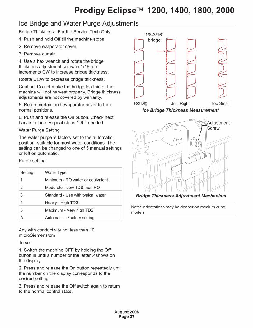
Ice Bridge and Water Purge AdjustmentsBridge Thickness - For the Service Tech Only
1. Push and hold Off till the machine stops.
2. Remove evaporator cover.
3. Remove curtain.
4. Use a hex wrench and rotate the bridgethickness adjustment screw in 1/16 turnincrements CW to increase bridge thickness.
Rotate CCW to decrease bridge thickness.
Caution: Do not make the bridge too thin or themachine will not harvest properly. Bridge thicknessadjustments are not covered by warranty.
5. Return curtain and evaporator cover to theirnormal positions.
6. Push and release the On button. Check nextharvest of ice. Repeat steps 1-6 if needed.
Water Purge Setting
The water purge is factory set to the automaticposition, suitable for most water conditions. Thesetting can be changed to one of 5 manual settingsor left on automatic.
Purge setting
Setting Water Type
1 Minimum - RO water or equivalent
2 Moderate - Low TDS, non RO
3 Standard - Use with typical water
4 Heavy - High TDS
5 Maximum - Very high TDS
A Automatic - Factory setting
Any with conductivity not less than 10microSiemens/cm
To set:
1. Switch the machine OFF by holding the Offbutton in until a number or the letter A shows onthe display.
2. Press and release the On button repeatedly untilthe number on the display corresponds to thedesired setting.
3. Press and release the Off switch again to returnto the normal control state.
Note: Indentations may be deeper on medium cube
models
Prodigy Eclipse� 1200, 1400, 1800, 2000
August 2008Page 27
Bridge Thickness Adjustment Mechanism
Ice Bridge Thickness Measurement
1/8-3/16"bridge
AdjustmentScrew
Too Big Too SmallJust Right
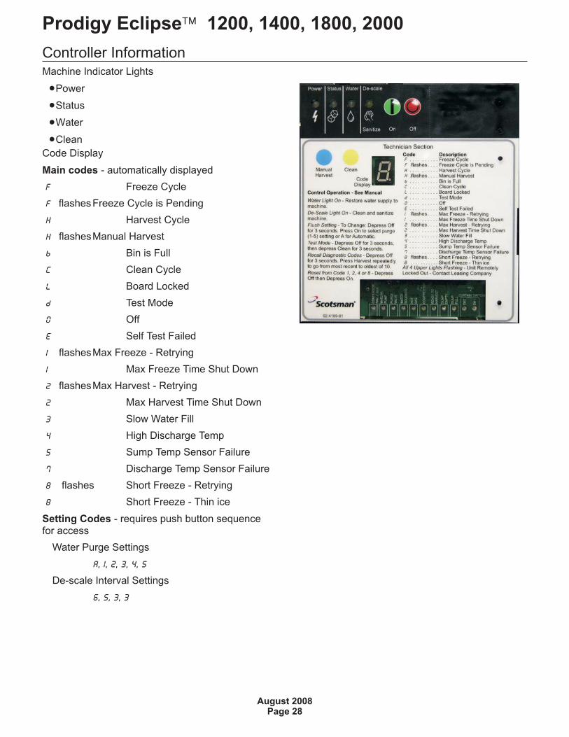
Controller InformationMachine Indicator Lights
�Power
�Status
�Water
�Clean
Code Display
Main codes - automatically displayed
F Freeze Cycle
F flashesFreeze Cycle is Pending
H Harvest Cycle
H flashesManual Harvest
b Bin is Full
C Clean Cycle
L Board Locked
d Test Mode
O Off
E Self Test Failed
1 flashesMax Freeze - Retrying
1 Max Freeze Time Shut Down
2 flashesMax Harvest - Retrying
2 Max Harvest Time Shut Down
3 Slow Water Fill
4 High Discharge Temp
5 Sump Temp Sensor Failure
7 Discharge Temp Sensor Failure
8 flashes Short Freeze - Retrying
8 Short Freeze - Thin ice
Setting Codes - requires push button sequencefor access
Water Purge Settings
A, 1, 2, 3, 4, 5
De-scale Interval Settings
6, 5, 3, 3
Prodigy Eclipse� 1200, 1400, 1800, 2000
August 2008Page 28
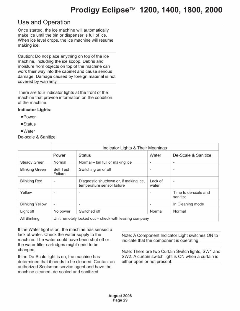
Use and OperationOnce started, the ice machine will automaticallymake ice until the bin or dispenser is full of ice.When ice level drops, the ice machine will resumemaking ice.
Caution: Do not place anything on top of the icemachine, including the ice scoop. Debris andmoisture from objects on top of the machine canwork their way into the cabinet and cause seriousdamage. Damage caused by foreign material is notcovered by warranty.
There are four indicator lights at the front of themachine that provide information on the conditionof the machine.
Indicator Lights:
�Power
�Status
�Water
De-scale & Sanitize
Indicator Lights & Their Meanings
Power Status Water De-Scale & Sanitize
Steady Green Normal Normal – bin full or making ice - -
Blinking Green Self TestFailure
Switching on or off - -
Blinking Red - Diagnostic shutdown or, if making ice,temperature sensor failure
Lack ofwater
-
Yellow - - - Time to de-scale andsanitize
Blinking Yellow - - - In Cleaning mode
Light off No power Switched off Normal Normal
All Blinking Unit remotely locked out – check with leasing company
If the Water light is on, the machine has sensed alack of water. Check the water supply to themachine. The water could have been shut off orthe water filter cartridges might need to bechanged.
If the De-Scale light is on, the machine hasdetermined that it needs to be cleaned. Contact anauthorized Scotsman service agent and have themachine cleaned, de-scaled and sanitized.
Prodigy Eclipse� 1200, 1400, 1800, 2000
August 2008Page 29
Note: A Component Indicator Light switches ON toindicate that the component is operating.
Note: There are two Curtain Switch lights, SW1 andSW2. A curtain switch light is ON when a curtain iseither open or not present.
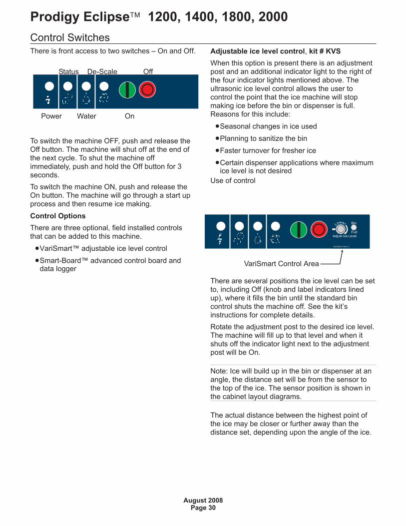
Control SwitchesThere is front access to two switches – On and Off.
To switch the machine OFF, push and release theOff button. The machine will shut off at the end ofthe next cycle. To shut the machine offimmediately, push and hold the Off button for 3seconds.
To switch the machine ON, push and release theOn button. The machine will go through a start upprocess and then resume ice making.
Control Options
There are three optional, field installed controlsthat can be added to this machine.
�VariSmart™ adjustable ice level control
�Smart-Board™ advanced control board anddata logger
Adjustable ice level control, kit # KVS
When this option is present there is an adjustmentpost and an additional indicator light to the right ofthe four indicator lights mentioned above. Theultrasonic ice level control allows the user tocontrol the point that the ice machine will stopmaking ice before the bin or dispenser is full.Reasons for this include:
�Seasonal changes in ice used
�Planning to sanitize the bin
�Faster turnover for fresher ice
�Certain dispenser applications where maximumice level is not desired
Use of control
There are several positions the ice level can be setto, including Off (knob and label indicators linedup), where it fills the bin until the standard bincontrol shuts the machine off. See the kit’sinstructions for complete details.
Rotate the adjustment post to the desired ice level.The machine will fill up to that level and when itshuts off the indicator light next to the adjustmentpost will be On.
Note: Ice will build up in the bin or dispenser at anangle, the distance set will be from the sensor tothe top of the ice. The sensor position is shown inthe cabinet layout diagrams.
The actual distance between the highest point ofthe ice may be closer or further away than thedistance set, depending upon the angle of the ice.
Prodigy Eclipse� 1200, 1400, 1800, 2000
August 2008Page 30
Power Water On
Status De-Scale Off
02-4294-01 Rev. A.
Adjust Ice Level
Lower Bin
Full
VariSmart Control Area
Options
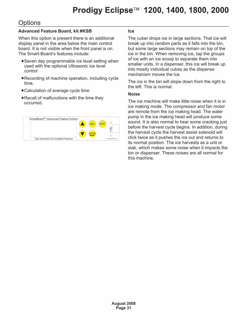
Advanced Feature Board, kit #KSB
When this option is present there is an additionaldisplay panel in the area below the main controlboard. It is not visible when the front panel is on.The Smart-Board’s features include:
�Seven day programmable ice level setting whenused with the optional Ultrasonic ice levelcontrol
�Recording of machine operation, including cycletime.
�Calculation of average cycle time
�Recall of malfunctions with the time theyoccurred.
Ice
The cuber drops ice in large sections. That ice willbreak up into random parts as it falls into the bin,but some large sections may remain on top of theice in the bin. When removing ice, tap the groupsof ice with an ice scoop to separate them intosmaller units. In a dispenser, this ice will break upinto mostly individual cubes as the dispensemechanism moves the ice.
The ice in the bin will slope down from the right tothe left. This is normal.
Noise
The ice machine will make little noise when it is inice making mode. The compressor and fan motorare remote from the ice making head. The waterpump in the ice making head will produce somesound. It is also normal to hear some cracking justbefore the harvest cycle begins. In addition, duringthe harvest cycle the harvest assist solenoid willclick twice as it pushes the ice out and returns toits normal position. The ice harvests as a unit orslab, which makes some noise when it impacts thebin or dispenser. These noises are all normal forthis machine.
Prodigy Eclipse� 1200, 1400, 1800, 2000
August 2008Page 31
SmartBoard Advanced Feature Control™
See Instructions for Available Features
34SEL
02-4293-01 Rev A.
ENTER
ESC
System Operation:This section is intended for the technician.Understanding it is not necessary for the normaloperation and maintenance of this ice makingsystem.
Major Components:
Ice making section sub-system:
�Controller,
�Water Level Sensor,
�Transformer,
�Evaporators,
�Expansion Valves,
�Vapor Inlet Valves,
�Water Pump,
�Inlet Water Valve
�Purge Valve.
�Harvest Assist Solenoids
Compressor Package sub-system:
�Compressor,
�Contactor,
�Condenser Bypass Valve,
�Liquid Inlet Valve,
�Receiver,
�Accumulator,
�CPR Valve,
�Headmaster.
Condenser sub-system:
�Coils
�Fan Motor
Freeze:
In the air cooled condensing unit sub-system(compressor package and condenser) thecompressor is on, the condenser by-pass valve isclosed, the fan motor is rotating the fan blade.
Harvest:
During harvest the compressor and fan motorcontinue to operate. The vapor inlet, condenserbypass, receiver inlet and harvest assist solenoidsare energized.
Ice releases and falls into the bin or dispenser.
Prodigy Eclipse� 1200, 1400, 1800, 2000
August 2008Page 32
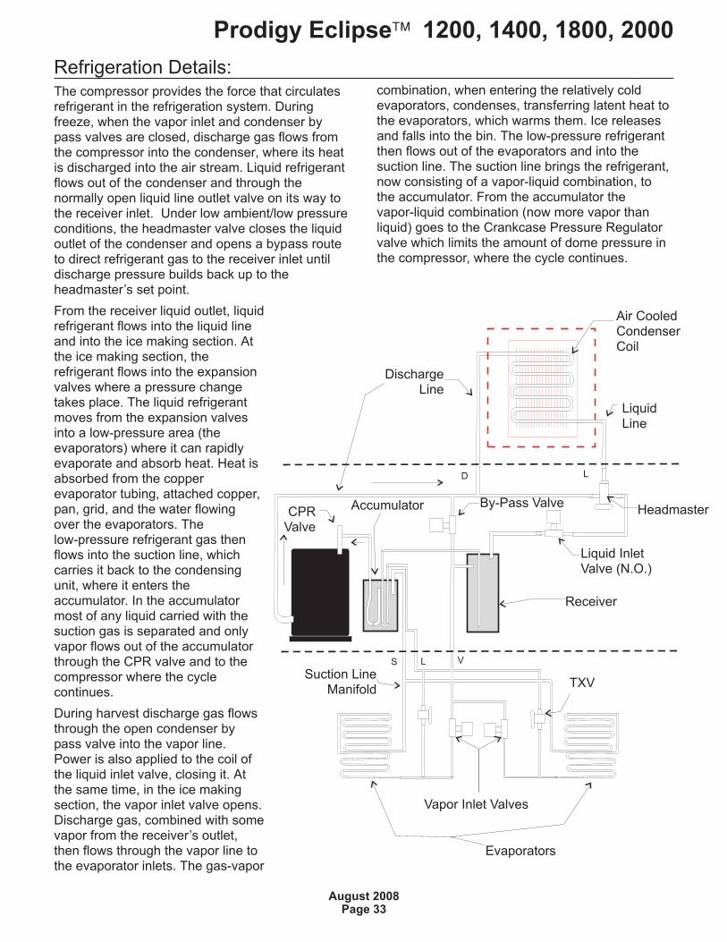
Refrigeration Details:The compressor provides the force that circulatesrefrigerant in the refrigeration system. Duringfreeze, when the vapor inlet and condenser bypass valves are closed, discharge gas flows fromthe compressor into the condenser, where its heatis discharged into the air stream. Liquid refrigerantflows out of the condenser and through thenormally open liquid line outlet valve on its way tothe receiver inlet. Under low ambient/low pressureconditions, the headmaster valve closes the liquidoutlet of the condenser and opens a bypass routeto direct refrigerant gas to the receiver inlet untildischarge pressure builds back up to theheadmaster’s set point.
From the receiver liquid outlet, liquidrefrigerant flows into the liquid lineand into the ice making section. Atthe ice making section, therefrigerant flows into the expansionvalves where a pressure changetakes place. The liquid refrigerantmoves from the expansion valvesinto a low-pressure area (theevaporators) where it can rapidlyevaporate and absorb heat. Heat isabsorbed from the copperevaporator tubing, attached copper,pan, grid, and the water flowingover the evaporators. Thelow-pressure refrigerant gas thenflows into the suction line, whichcarries it back to the condensingunit, where it enters theaccumulator. In the accumulatormost of any liquid carried with thesuction gas is separated and onlyvapor flows out of the accumulatorthrough the CPR valve and to thecompressor where the cyclecontinues.
During harvest discharge gas flowsthrough the open condenser bypass valve into the vapor line.Power is also applied to the coil ofthe liquid inlet valve, closing it. Atthe same time, in the ice makingsection, the vapor inlet valve opens.Discharge gas, combined with somevapor from the receiver’s outlet,then flows through the vapor line tothe evaporator inlets. The gas-vapor
combination, when entering the relatively coldevaporators, condenses, transferring latent heat tothe evaporators, which warms them. Ice releasesand falls into the bin. The low-pressure refrigerantthen flows out of the evaporators and into thesuction line. The suction line brings the refrigerant,now consisting of a vapor-liquid combination, tothe accumulator. From the accumulator thevapor-liquid combination (now more vapor thanliquid) goes to the Crankcase Pressure Regulatorvalve which limits the amount of dome pressure inthe compressor, where the cycle continues.
Prodigy Eclipse� 1200, 1400, 1800, 2000
August 2008Page 33
DischargeLine
Headmaster
Liquid InletValve (N.O.)
By-Pass Valve
TXV
Vapor Inlet Valves
Evaporators
Receiver
LiquidLine
CPRValve
Suction LineManifold
Accumulator
Air CooledCondenserCoil
D L
L VS
Technicians Only: Freeze Cycle Sequence of OperationThis sequence begins with a restart after the unithas shut off with the bin full. Ice has beenconsumed, causing the ice sensors to becomeun-blocked.
1. The controller (four minutes has to have passedsince the machine shut off on bin full for themachine to restart)
2. The purge valve is opened and the pumpstarted.
3. After the purge valve closes the inlet water valveopens and fills the reservoir.
Note: If the water reservoir does not fill within thetime period expected the controller will shut off andswitch on the water indicator light. It will re-try to fillthe reservoir in 20 minutes. If successful the freezecycle will continue.
4. The compressor and fan motor start and thefreezing process begins.
Note: The controller is connected to two externalrelays in the EH, one for the CP's compressorcontactor and the other for the CP's solenoidvalves. A separate 24 volt transformer is in the CPsupplying power to the contacts of these two linevoltage relays through the interconnecting wire.
5. The controller will shut the water pump off for afew seconds when the reservoir’s watertemperature reaches a pre-set point.
6. The freeze cycle continues until water makescontinuous contact with the ice thickness sensor.That signals the controller to terminate the freezecycle and begin the harvest cycle. The Ready toHarvest light will be ON.
.
Prodigy Eclipse� 1200, 1400, 1800, 2000
August 2008Page 34
Technicians Only: Harvest Cycle Sequence of OperationWhen harvest begins, the controller connectspower to the external relay for the CP's solenoids.
It also connects power to the vapor inlet solenoidvalve in the cabinet of the EH.
The vapor inlet solenoid valve and the condenserbypass valve open. The receiver inlet solenoidvalve closes. Vapor flows from the condensing unitto the EH evaporator inlets.
The water pump and purge valve will be on for aperiod of time during the first part of harvest topurge the water reservoir of a portion of the water.The inlet water solenoid valve opens to fill thereservoir when the water level sensor indicates anempty sump. It continues to fill when the pump andpurge valve have shut off and will stop filling whenthe water level sensor senses a full sump.
Harvest will continue until both curtains haveopened. The curtain switch, attached to the edgeof each curtain, will sense the curtain opening.
If the curtains both close, harvest will terminateand the freeze cycle will resume.
If one or both of the curtains remains open for 30seconds, the machine will shut down.
Prodigy Eclipse� 1200, 1400, 1800, 2000
August 2008Page 35
Control Safeties
Max freeze time – 45 minutes
When exceeded, the controller will attempt anotherfreeze cycle. If the condition is exceeded again thenext cycle, the control will again attempt anotherfreeze cycle. If the freeze cycle exceeds themaximum time in 3 consecutive cycles, thecontroller will shut the machine off and it must bemanually reset.
Min freeze time – 6 minutes
If the controller switches the machine into harvestwithin 20 seconds of the minimum freeze time, thecontroller will harvest for a preset time and doesnot stop if the curtain switch opens. If this occursagain in the next three cycles, the machine willshut down and must be manually reset.
Max harvest time – 3.5 minutes
If the harvest cycle has continued for 3.5 minuteswithout the curtain opening, the controller will shutthe machine off for 50 minutes and then restart. Ifthere is another the machine will shut the machineoff for another 50 minutes and then restart. If it failsa third consecutive time the controller will shut themachine down and must be manually reset.
�Time between resets – 50 minutes
�Number of automatic resets – 2
�Max water fill time – 5 minutes. Machine willattempt a restart every 20 minutes.
�Max discharge temp – 250 degrees F.
�Time interval between cleanings – 6 monthspower on time - adjustable in one monthincrements, can be set at 6, 5, 4 or 3 months ofpower up time.
�Manual harvest time – 3 minutes
�Pump down interval – remote only. 12 hours.Pump down is 30 seconds of compressor onlyon time.
�Minimum compressor off time – 4 minutes
�Continuous Run Time Maximum Cycles - 25
Restarts
Power Interruption
The controller will automatically restart the icemachine after adequate voltage has been restored.
�H blinks on code display
�Status indicator light blinks
�Reservoir is drained and refilled
�Default harvest is initiated. The curtain switchdoes not have to open to terminate harvest,harvest will continue until the default harvesttime expires. Default harvest time is 3 minutes.The machine will then return to a normal freezecycle.
Water Interruption
The controller will attempt to fill the reservoir everytwenty minutes until it is successful.
Prodigy Eclipse� 1200, 1400, 1800, 2000
August 2008Page 36
Controller Operation
Control Button Use (from standby)
Set purge level, 1-5 (1 is minimum, 5 is maximum)or Automatic:
�Hold off button in for 3 seconds. Release.
�Press and release the On button to cyclethrough and select one of the five purgesettings or to use the Automatic setting.
Recall diagnostic code:
�Hold off button in for 3 seconds. Release.
�Press and release the Harvest button to cyclethrough each of the last 10 error codes frommost recent to oldest.
Clear diagnostic code:
�Hold Clean and Harvest buttons in for 3seconds to clear all prior codes.
Reset control:
�Depress and release Off, then depress andrelease On
Start Test Mode:
�Hold Off button in for 3 seconds. Release.
�Hold Clean button in for 3 seconds. Release.
Lock Unlock control:
�Hold On button in for 3 seconds, keep holdingthen press and release Off twice.
Empty reservoir:
�Hold Clean button in for 3 seconds. Release.Pump and purge valve will be ON for 30seconds. Repeat as needed.
Test Mode:
�Depress Off for 3 seconds, release. Thendepress Clean for 3 seconds.
�The sump will fill the first 30 seconds of the test.If the sump is full it will overflow into the bin. At30 seconds the Water Inlet Valve will shut offand the Water Pump will turn on. You will beable to see and hear the water running over theplates. After 10 seconds the Purge and VaporInlet Valves will turn on. Water will be purgingfrom the machine. After 10 more seconds thecompressor will start. 5 seconds later the VIVwill close. The compressor will run for a total of20 seconds. After which everything will turn offfor 5 seconds. After that time the VIV will openand you’ll be able to hear the hissing as thepressure is equalized. 10 seconds later the fanwill turn on (if air cooled). After 10 seconds allwill be off and the output test will be complete.
Change De-Scale Notification Interval
Like the others, this feature is accessible only fromstandby (Status Light Off).
�Press and hold harvest button for 3 seconds.
�This will allow control to enter Time to CleanAdjustment State.
�Display current time to clean months on 7segment display.
�Pressing clean button repeatedly will cyclethrough one of 4 possible settings:
6 months (4380 hours) (default)
5 months (3650 hrs)
4 months (2920 hrs)
3 months (2190 hrs)
Prodigy Eclipse� 1200, 1400, 1800, 2000
August 2008Page 37
Cleaning, Sanitation and MaintenanceThis ice system requires three types ofmaintenance:
• Remove the build up of mineral scale from the ice machine’s water system and sensors.
• Sanitize the ice machine’s water system and the ice storage bin or dispenser.
• Clean the air cooled condenser.
It is the User’s responsibility to keep the ice machine and ice storage bin in a sanitary condition. Withouthuman intervention, sanitation will not be maintained. Ice machines also require occasional cleaning oftheir water systems with a specifically designed chemical. This chemical dissolves mineral build up thatforms during the ice making process.
Sanitize the ice storage bin as frequently as local health codes require, and every time the ice machine iscleaned and sanitized.
The ice machine’s water system should be cleaned and sanitized a minimum of twice per year.
1. Remove the front panel.
2. Remove the evaporator cover.
3. If the machine is operating, push and releasethe Harvest button. When the machinecompletes the Harvest cycle it will stop. If thebin is full (b shows in display) push and releasethe Off button.
4. Remove all ice from the storage bin ordispenser.
5. Push and release the Clean button. The yellowClean light will blink and the display will showC. The machine will drain the reservoir andrefill it. Go onto the next step when thereservoir has filled.
6. Pour 24 ounces of Scotsman Clear 1 nickelsafe scale remover into the reservoir.
7. Allow the ice machine cleaner to circulate inthe water system for at least 10 minutes.
8. Push and release the Clean button again. Theyellow Clean light will be on continuously andthe machine will drain and refill the reservoir toflush out the ice machine cleaner and residue.
9. Allow the drain and refill process to continuefor at least 20 minutes.
10. Push and release the Off button. The cleancycle will stop and the display will show O.
Note: If unit has not been de-scaled for anextended period of time and significant mineralscale remains, repeat steps 5 - 10.
11. Mix a cleaning solution of 1 oz of ice machinecleaner to 12 ounces of water.
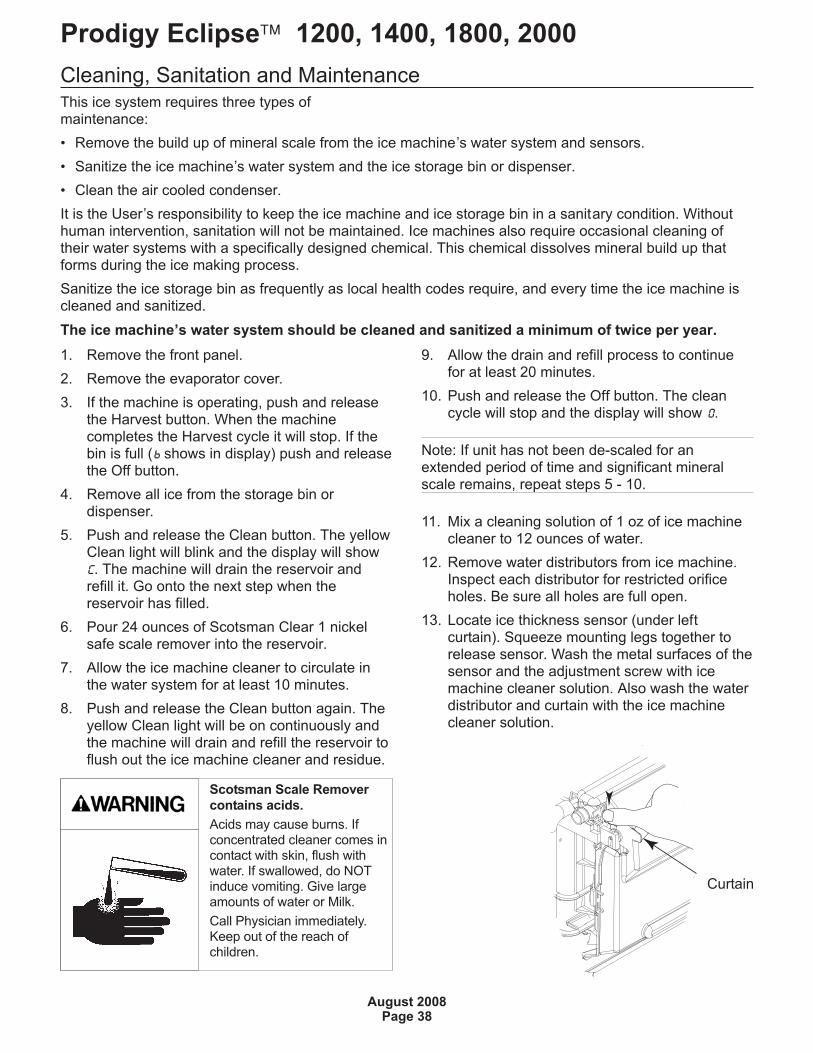
12. Remove water distributors from ice machine.Inspect each distributor for restricted orificeholes. Be sure all holes are full open.
13. Locate ice thickness sensor (under leftcurtain). Squeeze mounting legs together torelease sensor. Wash the metal surfaces of thesensor and the adjustment screw with icemachine cleaner solution. Also wash the waterdistributor and curtain with the ice machinecleaner solution.
Prodigy Eclipse� 1200, 1400, 1800, 2000
August 2008Page 38
Scotsman Scale Remover
contains acids.
Acids may cause burns. Ifconcentrated cleaner comes incontact with skin, flush withwater. If swallowed, do NOTinduce vomiting. Give largeamounts of water or Milk.
Call Physician immediately.Keep out of the reach ofchildren.
Curtain
14. Locate water level sensor. Squeeze catchestogether and pull up to remove sensor. Washmetal surfaces of sensor with ice machinecleaner solution.
15. Mix a solution of locally approved sanitizer.
Note; A possible sanitizing solution may be madeby mixing 1 ounce of liquid household bleach with2 gallons of warm (95-115
oF.) potable water.
16. Thoroughly wash all surfaces of the icethickness sensor, water level sensor, curtainand water distributor with the sanitizer solution.
17. Thoroughly wash all interior surfaces of thefreezing compartment, including evaporatorframes, back wall, evaporator cover and thepart of the top panel covering the freezingcompartment with the sanitizer solution.
18. Return water level sensor, ice thicknesssensor, water distributors and curtains to theirnormal positions.
19. Push and hold the clean button to drain thereservoir. Push and release the clean buttonagain and when the flush valve indicator lightgoes out, immediately pour the remainingcleaning solution into the reservoir.
20. Circulate the sanitizer solution for 10 minutes,then push and release the Clean button.
21. Allow the water system to be flushed ofsanitizer for at least 20 minutes, then push andrelease the Off button.
22. Return the evaporator cover and front panel totheir normal position and secure with theoriginal fasteners.
23. Push and release the On button to resume icemaking.
Other Maintenance
The remote air cooled condenser coil must becleaned occasionally to keep the system operatingat high efficiency.
�Remove any large debris from the outside of thecoil.
�Vacuum accumulated dust.
�Wash out the coils with water.
Caution: Do NOT use excessive water pressure asthat will bend the fins.
�Straighten any damaged fins with a fin comb.
�If the coils have become coated with grease, acoil cleaner will have to be used to wash thecoils.
Disconnect power to the condensing unit andremove the condenser top.
�Inspect the fan blade to be sure it is not crackedand is clean.
Return the condenser top to its original positionand reconnect the power supply.
Prodigy Eclipse� 1200, 1400, 1800, 2000
August 2008Page 39
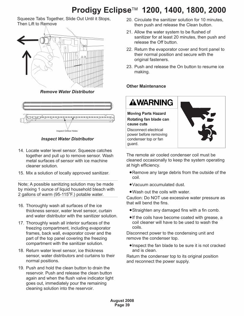
Moving Parts Hazard
Rotating fan blade can
cause cuts
Disconnect electricalpower before removingcondenser top or fanguard.
Remove Water Distributor
Squeeze Tabs Together, Slide Out Until it Stops,Then Lift to Remove
Inspect Orifice Holes
Inspect Water Distributor
Service Diagnosis
Prodigy Eclipse� 1200, 1400, 1800, 2000
August 2008Page 40
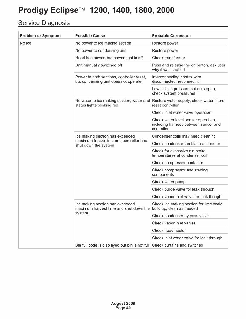
Problem or Symptom Possible Cause Probable Correction
No ice No power to ice making section Restore power
No power to condensing unit Restore power
Head has power, but power light is off Check transformer
Unit manually switched off Push and release the on button, ask userwhy it was shut off
Power to both sections, controller reset,but condensing unit does not operate
Interconnecting control wiredisconnected, reconnect it
Low or high pressure cut outs open,check system pressures
No water to ice making section, water andstatus lights blinking red
Restore water supply, check water filters,reset controller
Check inlet water valve operation
Check water level sensor operation,including harness between sensor andcontroller.
Ice making section has exceededmaximum freeze time and controller hasshut down the system
Condenser coils may need cleaning
Check condenser fan blade and motor
Check for excessive air intaketemperatures at condenser coil
Check compressor contactor
Check compressor and startingcomponents
Check water pump
Check purge valve for leak through
Check vapor inlet valve for leak though
Ice making section has exceededmaximum harvest time and shut down thesystem
Check ice making section for lime scalebuild up, clean as needed
Check condenser by pass valve
Check vapor inlet valves
Check headmaster
Check inlet water valve for leak through
Bin full code is displayed but bin is not full Check curtains and switches
Service Diagnosis
Prodigy Eclipse� 1200, 1400, 1800, 2000
August 2008Page 41
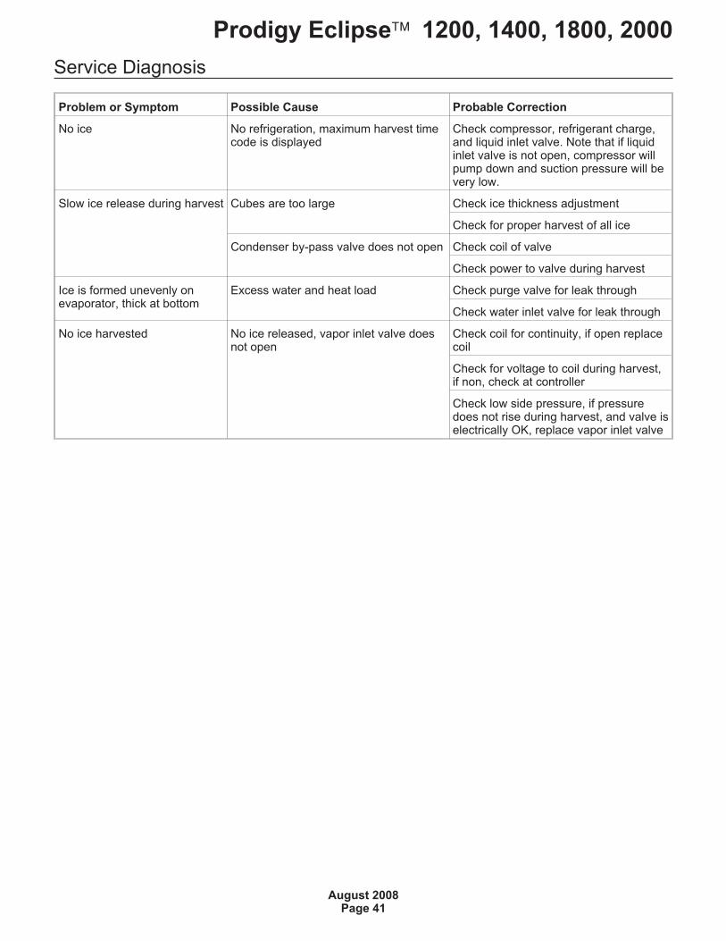
Problem or Symptom Possible Cause Probable Correction
No ice No refrigeration, maximum harvest timecode is displayed
Check compressor, refrigerant charge,and liquid inlet valve. Note that if liquidinlet valve is not open, compressor willpump down and suction pressure will bevery low.
Slow ice release during harvest Cubes are too large Check ice thickness adjustment
Check for proper harvest of all ice
Condenser by-pass valve does not open Check coil of valve
Check power to valve during harvest
Ice is formed unevenly onevaporator, thick at bottom
Excess water and heat load Check purge valve for leak through
Check water inlet valve for leak through
No ice harvested No ice released, vapor inlet valve doesnot open
Check coil for continuity, if open replacecoil
Check for voltage to coil during harvest,if non, check at controller
Check low side pressure, if pressuredoes not rise during harvest, and valve iselectrically OK, replace vapor inlet valve
Service Diagnosis
Prodigy Eclipse� 1200, 1400, 1800, 2000
August 2008Page 42
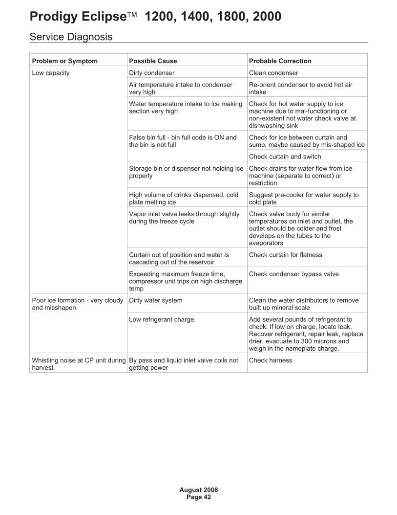
Problem or Symptom Possible Cause Probable Correction
Low capacity Dirty condenser Clean condenser
Air temperature intake to condenservery high
Re-orient condenser to avoid hot airintake
Water temperature intake to ice makingsection very high
Check for hot water supply to icemachine due to mal-functioning ornon-existent hot water check valve atdishwashing sink
False bin full - bin full code is ON andthe bin is not full
Check for ice between curtain andsump, maybe caused by mis-shaped ice
Check curtain and switch
Storage bin or dispenser not holding iceproperly
Check drains for water flow from icemachine (separate to correct) orrestriction
High volume of drinks dispensed, coldplate melting ice
Suggest pre-cooler for water supply tocold plate
Vapor inlet valve leaks through slightlyduring the freeze cycle
Check valve body for similartemperatures on inlet and outlet, theoutlet should be colder and frostdevelops on the tubes to theevaporators
Curtain out of position and water iscascading out of the reservoir
Check curtain for flatness
Exceeding maximum freeze time,compressor unit trips on high dischargetemp
Check condenser bypass valve
Poor ice formation - very cloudyand misshapen
Dirty water system Clean the water distributors to removebuilt up mineral scale
Low refrigerant charge. Add several pounds of refrigerant tocheck. If low on charge, locate leak.Recover refrigerant, repair leak, replacedrier, evacuate to 300 microns andweigh in the nameplate charge.
Whistling noise at CP unit duringharvest
By pass and liquid inlet valve coils notgetting power
Check harness
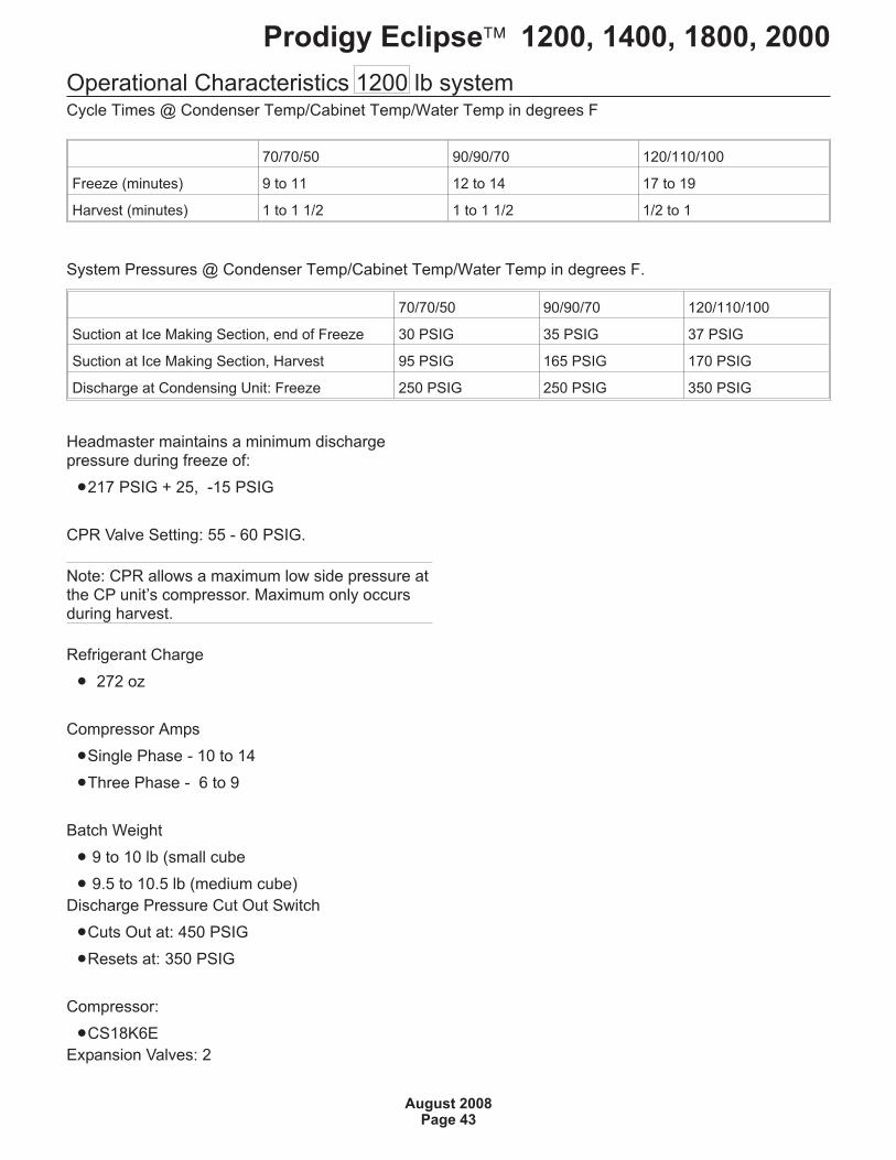
Operational Characteristics 1200 lb systemCycle Times @ Condenser Temp/Cabinet Temp/Water Temp in degrees F
System Pressures @ Condenser Temp/Cabinet Temp/Water Temp in degrees F.
Headmaster maintains a minimum dischargepressure during freeze of:
�217 PSIG + 25, -15 PSIG
CPR Valve Setting: 55 - 60 PSIG.
Note: CPR allows a maximum low side pressure atthe CP unit’s compressor. Maximum only occursduring harvest.
Refrigerant Charge
� 272 oz
Compressor Amps
�Single Phase - 10 to 14
�Three Phase - 6 to 9
Batch Weight
� 9 to 10 lb (small cube
� 9.5 to 10.5 lb (medium cube)
Discharge Pressure Cut Out Switch
�Cuts Out at: 450 PSIG
�Resets at: 350 PSIG
Compressor:
�CS18K6E
Expansion Valves: 2
Prodigy Eclipse� 1200, 1400, 1800, 2000
August 2008Page 43
70/70/50 90/90/70 120/110/100
Freeze (minutes) 9 to 11 12 to 14 17 to 19
Harvest (minutes) 1 to 1 1/2 1 to 1 1/2 1/2 to 1
70/70/50 90/90/70 120/110/100
Suction at Ice Making Section, end of Freeze 30 PSIG 35 PSIG 37 PSIG
Suction at Ice Making Section, Harvest 95 PSIG 165 PSIG 170 PSIG
Discharge at Condensing Unit: Freeze 250 PSIG 250 PSIG 350 PSIG
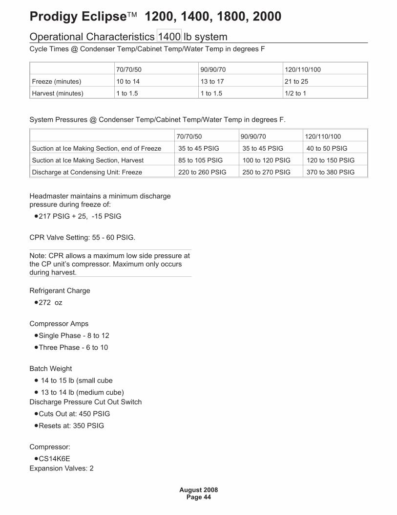
Operational Characteristics 1400 lb systemCycle Times @ Condenser Temp/Cabinet Temp/Water Temp in degrees F
System Pressures @ Condenser Temp/Cabinet Temp/Water Temp in degrees F.
Headmaster maintains a minimum dischargepressure during freeze of:
�217 PSIG + 25, -15 PSIG
CPR Valve Setting: 55 - 60 PSIG.
Note: CPR allows a maximum low side pressure atthe CP unit’s compressor. Maximum only occursduring harvest.
Refrigerant Charge
�272 oz
Compressor Amps
�Single Phase - 8 to 12
�Three Phase - 6 to 10
Batch Weight
� 14 to 15 lb (small cube
� 13 to 14 lb (medium cube)
Discharge Pressure Cut Out Switch
�Cuts Out at: 450 PSIG
�Resets at: 350 PSIG
Compressor:
�CS14K6E
Expansion Valves: 2
Prodigy Eclipse� 1200, 1400, 1800, 2000
August 2008Page 44
70/70/50 90/90/70 120/110/100
Freeze (minutes) 10 to 14 13 to 17 21 to 25
Harvest (minutes) 1 to 1.5 1 to 1.5 1/2 to 1
70/70/50 90/90/70 120/110/100
Suction at Ice Making Section, end of Freeze 35 to 45 PSIG 35 to 45 PSIG 40 to 50 PSIG
Suction at Ice Making Section, Harvest 85 to 105 PSIG 100 to 120 PSIG 120 to 150 PSIG
Discharge at Condensing Unit: Freeze 220 to 260 PSIG 250 to 270 PSIG 370 to 380 PSIG
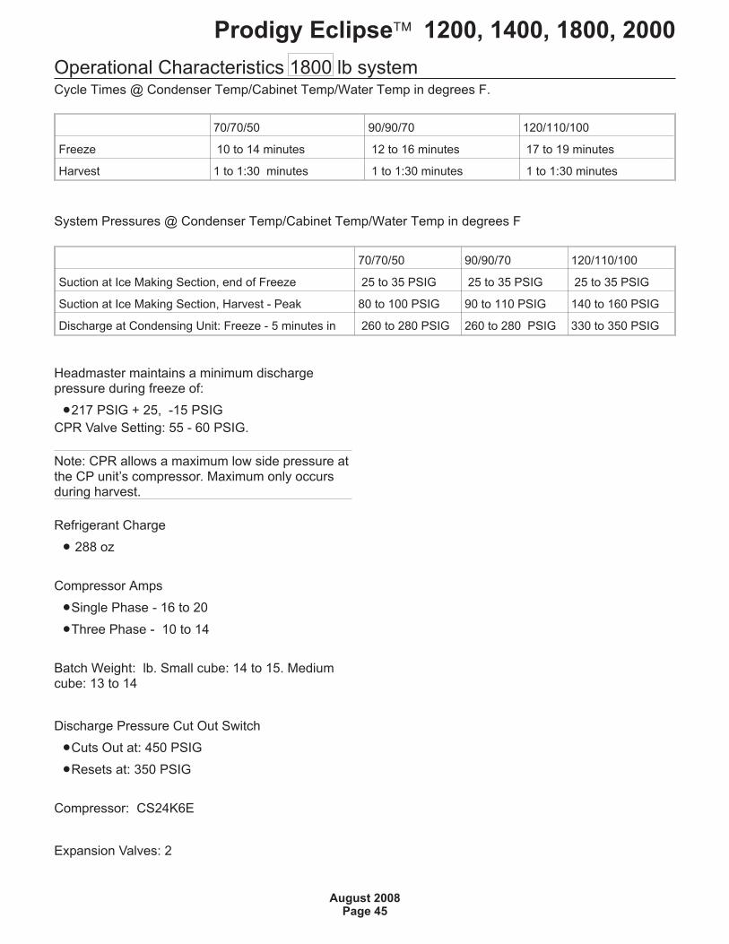
Operational Characteristics 1800 lb systemCycle Times @ Condenser Temp/Cabinet Temp/Water Temp in degrees F.
System Pressures @ Condenser Temp/Cabinet Temp/Water Temp in degrees F
Headmaster maintains a minimum dischargepressure during freeze of:
�217 PSIG + 25, -15 PSIG
CPR Valve Setting: 55 - 60 PSIG.
Note: CPR allows a maximum low side pressure atthe CP unit’s compressor. Maximum only occursduring harvest.
Refrigerant Charge
� 288 oz
Compressor Amps
�Single Phase - 16 to 20
�Three Phase - 10 to 14
Batch Weight: lb. Small cube: 14 to 15. Mediumcube: 13 to 14
Discharge Pressure Cut Out Switch
�Cuts Out at: 450 PSIG
�Resets at: 350 PSIG
Compressor: CS24K6E
Expansion Valves: 2
Prodigy Eclipse� 1200, 1400, 1800, 2000
August 2008Page 45
70/70/50 90/90/70 120/110/100
Freeze 10 to 14 minutes 12 to 16 minutes 17 to 19 minutes
Harvest 1 to 1:30 minutes 1 to 1:30 minutes 1 to 1:30 minutes
70/70/50 90/90/70 120/110/100
Suction at Ice Making Section, end of Freeze 25 to 35 PSIG 25 to 35 PSIG 25 to 35 PSIG
Suction at Ice Making Section, Harvest - Peak 80 to 100 PSIG 90 to 110 PSIG 140 to 160 PSIG
Discharge at Condensing Unit: Freeze - 5 minutes in 260 to 280 PSIG 260 to 280 PSIG 330 to 350 PSIG
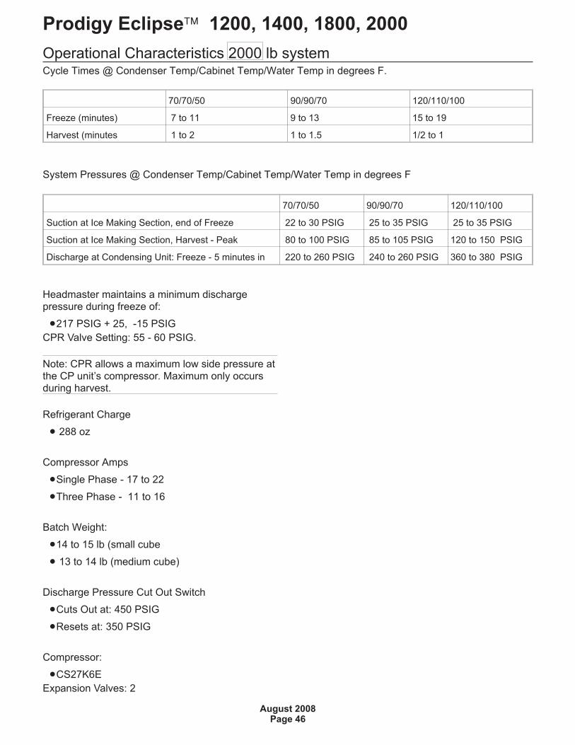
Operational Characteristics 2000 lb systemCycle Times @ Condenser Temp/Cabinet Temp/Water Temp in degrees F.
System Pressures @ Condenser Temp/Cabinet Temp/Water Temp in degrees F
Headmaster maintains a minimum dischargepressure during freeze of:
�217 PSIG + 25, -15 PSIG
CPR Valve Setting: 55 - 60 PSIG.
Note: CPR allows a maximum low side pressure atthe CP unit’s compressor. Maximum only occursduring harvest.
Refrigerant Charge
� 288 oz
Compressor Amps
�Single Phase - 17 to 22
�Three Phase - 11 to 16
Batch Weight:
�14 to 15 lb (small cube
� 13 to 14 lb (medium cube)
Discharge Pressure Cut Out Switch
�Cuts Out at: 450 PSIG
�Resets at: 350 PSIG
Compressor:
�CS27K6E
Expansion Valves: 2
Prodigy Eclipse� 1200, 1400, 1800, 2000
August 2008Page 46
70/70/50 90/90/70 120/110/100
Freeze (minutes) 7 to 11 9 to 13 15 to 19
Harvest (minutes 1 to 2 1 to 1.5 1/2 to 1
70/70/50 90/90/70 120/110/100
Suction at Ice Making Section, end of Freeze 22 to 30 PSIG 25 to 35 PSIG 25 to 35 PSIG
Suction at Ice Making Section, Harvest - Peak 80 to 100 PSIG 85 to 105 PSIG 120 to 150 PSIG
Discharge at Condensing Unit: Freeze - 5 minutes in 220 to 260 PSIG 240 to 260 PSIG 360 to 380 PSIG
Refrigeration System Service
Recovery
Recovery must be done from the condensing unit,but requires the ice machine to be shut down.
1. At the ice making section, remove the frontpanel.
2. Push and release the Harvest button. When themachine shuts off, recover the refrigerant.
3. Remove compressor package covers.
4. Attach recovery system to low side (compressorprocess port valve)
5. If the recovery system can recover liquid, attachrecovery system to high side (receiver liquid lineout valve)
Operate recovery system to remove refrigerantfrom the system. No other points of attachment orsolenoid activation are required.
Prodigy Eclipse� 1200, 1400, 1800, 2000
August 2008Page 47