Embed Size (px)
Citation preview

IEEE TRANSACTIONS ON MAGNETICS, VOL. MAG-20, NO. 2, MARCH 1984 373
PRODUCIBILITY I3PR-S AND MANLIFA"URE OF' A PROTM"I(PE CcBNERCm COMpAcT p w H ~ O F Q ~
J.M. Weldon, V i c e President, Research & Developwnt D.H. Pryor, Senior Vice President
O W , Inc., P.O. 4578, Odessa, Texas 79760
JNIRODUCI'ION
university of Texas a t Austin has developd the tech- nology for ' the design of an all iron rotating, 6.2 ma jou le canpact hampols generator. ,This generator was developd by.the Center for Electrachanics for the U. S. Amy Annarent Research and Develapment Caw mand under contract DAAK10-80-C-0309.2
OF, ~nc. negotiated an exclusive licer@ng agre&t with the University of. exa as for the c m - cia1 mufactwe of The Campact Pulsed Hcanopolar Gen- erator. I n order to m u f a c t q e t h i s product on a comnercial basis it was necessary to d i f y the m. design of the generator.to acccpnplish several goals.
The goals of the redesign were: to increase the machine's maximum design current output f m 750,000' to 1,000,000 amperes, to overcame or eliminate problems encountwed by CEM during their prototype generator construction, and t o d i f y the design t o we it mre ccpnpatible w i t h industrial production practices to al- law for parts interchangability . This paper describes these design modifications and reviews manufacturing problems and subsequent solutions which arose during the manufacture of the ODE,. Inc. Canpact Pulsed Hano- polar m e r a t o r prototype. Due t o manufacturing and raw material acquisition delays, testing of t h i s pro- tom generator has not been carrpleted a t the time of this writing, so consequently the p e r f o m c e evalua- tion of this unit cannot be reported i n this paper.
MACHINE DESCRIPTLON
The Center for Electrcmchanics (W) a t the
The hmpolar generator was conceived i n the eariy 1800's by Michael Faraday, and saw limited appli- cation for .the next 100 years as a direct current pw- er ,source. 1 In the last two decades the hcmpolar generator has ken the subject of considerable atten- tion as an energy storage device and subsequent pulsed duty generator. This. attention has lead to .nmrous advances in brush &d bearing technology, as well as improvements in the useful energy output per unit volm of the mchine. The CcoTp?act pulsed Homspolar Generator can be considered t o be a mechanical capac- i to r w i t h a very high variable equivalent capacitance. The machine stores energy in- the form .of rotational kinetic energy in the rotor and then discharges this energy' into a given electrical load. T h e . voltage pro- duced by this machine is a direct function. of the rotor speed and magnetic field strength and c+ be easily predicted frcin Faraday's Law of Electromagnetic Induc- tion.- As compared to other f o m of energy storage and high energy electrical pulse generators, the Ccarr pact Pulsed, H m p o l a r Generabr is an.eco&cal , re- liable, rugged, and highly versatile device for achiev- ing high amperagepdsed electrfcal discharges.
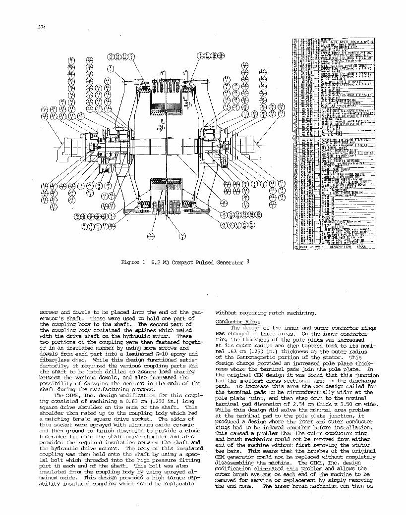
cross section in Figure '1 stores 6.2 mgajoules of energy a t a speed of '6245 rpn and w i l l produce 50 VDC terminal voltage a t this speed with full, field excita- tion. The machine has a minimun effective capacitance of 4960 farads coupled w i t h a very law impenaance of 7.5 microhms and 30 nanohenries. Tkis generator has a discharge current rating of 1,000,000 amperes, and produces a discharge torque of 81,000 newton-wters (60,000 foot-pounds) a t this current level. The total generator weight is 1600 kilograms (3530 pounds) and has overall outside dimmions of 83.9 an (33.02 in.) d i e t e r by 63.8 an (25.12 in.) long. The Campad pulsed Hmpolar Generator has an effective energy density of 3.875 kilojoules/kilogram or 17.6 megajoules /cubic mter.
The Compact Pulsea Homopolar Generator shown in
As shown in Figure 1, The Campact Pulsed Hompolar Generator .consists of a 770 kilogram (1700, p o u n d ) s p l shaped rotor assembly which has two electrically insulated rotor sections pressure fitted on a c m n shaft. This rotor assembly rotates inside the genera- tor housing on a pair of precision heavy duty needle bearings. Axial rotor.position is maintained through the use of a p a i r of 40° angular contact bal1,bearings. All bearings are pressure j e t lubricated and ps i t ive- l y scavanged to insure prowr bearing operation. Seal- ing between the bearing housing and the rotor cavity is provided by two teflon U-cup Bal-seals. The stator, field coil, and m e r brush mechanisms are located i n the space between the flanges of the rotor. The field coil consists of two 78 turn coils of 0.60 cm(0.235 in) square ,copper w i r e epoxy pt&d into a single structure. The inner brush mechanisms consist of two sets of 280 brushes each. These brushes are pneumatically accuat- ed in sets of 14 by 40 individual air bladders fed from a cormy3n a i r manifold. The outer brush mechan- isms .consist of two sets of 300 brushes each. These brkhes are pneumatically actuated in sets of six by 60 individual a i r bladders on each end of the machine. The outer brush bladders on each end of the machine are connected t o a c o m n a i r manifold. The inner brush mechanisms are munted on two inner conductor rings which each conduct the discharge current radially to 20 pairs of equally spaced terminal pads on the out- side circumference of the michine. The outer brush mechanisms are munted on two outer conductor rings which conduct the discharge qxrent to another 20 pairs of terminal pads. These terminal pads are arranged such that one terminal pad from each outer and each inner conductor ring are' located between the 20 structural t e e , bars ,which support the machine's end &res. Be- cause the Compact Pulsed Hmpolar Generator has two electrically isloated rotor sections, each having two sets of brushes associated w i t h them, this machine has two separate voltage producing paths through the rotor. This allows these two paths, which are capable of pro- ducing about 25 WC each and conducting 1 mega-ampere of current, t o be either connected in series to pro- duce a 50 W C / l . O mega-amp generator or in .parallel to produce a 25 WC/2.0 -a-amp generator. The re- mainder of the wchine consists mainly of the structur- al portion of the generator, m l y the bearing hous- ings, end cones, tee bars, and stator. All bearings in the bearing housings are electrically insulated frm the housing t o prevent circulating eddy currents f r m causing bearing damage due to race or roller arc- ing. The hydxaulic drive mtors are munted to the bearing housings using electrically insulated bolts and spacers, and these mtors are coupled to the generator rotor/shaft assembly through insulated coupl- ings. These steps prevent circulating eddy currents f n p possibly damaging the bearing i n the hydraulic mtors .
DESIGN MODIFICATIONS The OIME, Inc. prototype comrc ia l Compact Pulsed
H m p l q Generator d i f f e r s from the Center for Electro- mechanics' 6.2 megajoule prototype generator described in their September 1982 contract report in several ways. The major differences are described below.
Rotor-Shaft System
system was in the area of the insulated couplings used to couple the ends of the shaft to the hydraulic drive mtors. The original C3f design called for ml t ip l e
The only design change made on the rotor-shaft
0018-9464/84/0300-0373$01 .OO 0 1984 IEEE
3 74
Figure 1 6.2 Mj Capact Pulsed Generabr 3
screws and dowels to be placed into the end of the gen- erator's shaft. These were used t o hold one part of the coupling body to the shaft. The second part of the coupling M y contained the splines which mated w i t h the drive shaft on the hydraulic mtor. These two portions of the coupling were then fastened togeth- er in an insulated manner by using more screws and dowels from each part into a laminated G10 epoxy and fiberglass disc. While this design functioned satis- factorily, it required the various coupling parts and the shaft to be match drilled t o assure load sharing between the various dowels, and also increased the possibility of damaging the centers in the ends of the shaft during the manufacturing process.
ing consisted of machining a 0.63 cm (-250 in.) long square drive shoulder on the ends of the shaft. This shoulder then mted up t o the coupling body which had a matching female square drive socket. The sides of this socket were sprayed w i t h aluminum oxide ceramic and then ground to f inish dimension t o provide a close tolerance f i t onto the shaft drive shoulder and also provides the required insulation between the shaft and the hydraulic drive motors. The body of this insulated coupling was then held onto the shaft by using a spec- ia l bolt which threaded into the high pressure f i t t ing port in each end of the shaft. This bolt was also insulated from the coupling body by using sprayed al- Lrminum oxide. This design provided a high torque c a p ability insulated coupling which could be replacable
The OIME, Inc. design modification for this coupl-
without requiring match machining. Conductor Rings
The design of the inner and outer conductor rings w a s changed in three areas. On the inner conductor ring the thickness of the pole plate w a s increased at its outer radius and then tapered back t o its nomi- nal .63 cm ( .250 i n . ) thickness a t the outer radius of the ferromagnetic portion of the stator. This design change provided an increased pole plate thick- ness where the terminal pads join the pole plate. In the original CEM design it was found that this junction had the mllest C ~ C D S sectional area i n the discharge path. To increase this area the CEM design called for the terminal pads t o be c i r d r e n t i a l l y wider a t the pole plate joint, and then step down to the nominal terminal pad d b n s i o n of 2.54 cm thick x 3.50 cm wide. While this design did solve the minimal area problem at the terminal pad to the pole plate junction, it prcduced a design where the inner and outer conductor rings had to be indexed together before installation. This caused a problem that the outer conductor ring and brush mechanism could not be rmved from either end of the machine without f i r s t r m v i n g the stator tee bars. This means that the brushes of the original CEM generator could not be replaced without completely disassembling the machine. The O M , Inc. design Wif ica t ion eliminated this problem and allows the outer brush systems on each end of the machine to be r a v e d f o r service or replacement by sirply remving the end cone. The inner brush mechanism can then be
375
r m v e d by disassembling the rotor and extracting the inner conductor ring with the inner brush mchanism attached.
The second area of design change concerned the inner conductor to stator munting system. Because the inner conductor rings conduct the fu l l discharge current radially across the p l e facerthese conduc- tors see the fu l l discharge torque of the mchine. This requires that the rings be s t i f f ly munted t o each side of the stator core but still maintain elec- trical isolation from each other. The original CEM design used a cambination of steel core nylon clad f l a t head machine screws threaded into the face of the stator to provide axial confinemnt, and a set of ceramic insulated dowel pins between the conductor ring and the stator face to provide reaction torque confinenent. These dowels were necessary because the steel core nylon screws could not be used t o carry the shear load generated by the reaction torque on the pole plate. This design worked satisfactorily, but required that each conductor ring be matched doweled t o a particular stator face on a particular machine. This led to a problem of difficulty in part interchangability in a production generator. The OIME, Inc. solution t o this problem was t o use in- sulated dowels w i t h a threaded hole through their center shrunk f i t i n t o the steel core of the stator. This design in effect provided high strength ’elec- trically insulated threaded holes in each face of the stator. The inner conductor rings were then m u n t d t o the stator by using high strength Allen head button type cap screws,which can be torqued tight enough t o confine the applied reaction torque by way of fric- tion between the pole plate and the stator face.
ductor rings involved the material selection for the rings. The original CEM design called for the use of flat plates of ETP-110 c o m r t o be rolled and silver soldered into rings and then silver soldered t o the p l e plates and terminal bars to produce the finished product. This procedire led t o several problem areas during mufacture due t o thermal war- page of the plates and rings during the soldering process. The O M , Inc. design eliminated these pro- blems by substituting single piece forgings of ETP- 102 silver bearing copper. This material has a slight- ly better conductivity than the original ETP-110, and greatly simplified the mufacture of the conductor rings. Stator
sed Homoplar Generator was modified from the original CEM design in two areas. The f i r s t of these was in the specifications for the aluminum ring which was shrunk f i t onto the steel stator core. This ring which forms the imier brush m i f o l d a s well as providing the munting p i n t t o r the tee bars and termindl pad insulators was originally fabricated from a rolled and welded ring of 6061 T6 alloy aluminum It was found by CEM personnel that during the shrink f i t t ing process on this ring that the very high shrink f i t pressures required by the machine stiffness criter- ion caused this ring to break a t the weld on several tries. This problem eventually led t o a reduction in the desired shrink f i t pressure t o allow the use of the rolled and welded ring, and. then a subsequent mdification in the tee bar mounting system. The original design called for the tee bars t o be mounted w i t h bolts and dowels into the aluminurnsing only, thereby preserving the magnetic mass of the steel stator core. Because of the lower shrink f i t pres- sures obtained, this design was d i f i e d to use steel
The third area of design modification on the con-
The stator design on the OIME, Inc. Compact Pul-
over the steel studs. This in effect munted the tee bars t o the S t e e l core Of the stator without adversly effecting the magnetic flux pattern in the stator, and provided an adequate but expensive solution. The OIME, Inc. design called for the use of a high strength 7075-T6 aluminum rolled ring forging which could w i t h - stand the high shrink f i t forces t o be used, and then the original CEM design be reinstituted.
K W U E ’ A m M3DIFICATIONS The only major manufacturing modification which
OIME, Inc. initiated on the CEM production process was a t their suggestion and involved the sequence used in finish grinding the rotor and shaft. The original mufacturing sequence used by CEM t o make the finish- ed rotor was (1) finish machine the shaft; (2) ceramic spray appropriate areas of the shaft; (3) finish grind a l l surfaces on the shaft; (4) rough machine the rotor sections; (5) ceramic spray the rotor bores and center faces; (6) finish grind the rotor bores and center faces; (7) assemble the rotor sections on the shaft, and (8) finish grind the outside rotor surfaces t o camplete the sub-assembly. This sequence worked sat- isfactorily, but led t o one problem area. Because of the necessity of having the high pressure hydraulic ports located in the center of the ends of the shaft& allow for rotor section r m v a l from the shaft, .the machine centers i n the ends of the shaft are larger than centers typically used on this size rotor. These centers proved t o be somwhat undesirable during the grinding process on the rotors because of thermal distortion caused by excessive heating. This problem w a s campounded by the sequence requiring that the s m centers be used for two separate grinding steps, one on the shaft before the rotor assembly and one after assembly on the outside surfaces of the rotors. Since the surfaces produced during these two different grind- steps are required t o be highly accurate and have a total run out of less than 0.013 mn (0.0005 i n . ) it w a s found that the centers were not satisfactory and had to be reworked several times during the sequence.
The OIME, 1nc.dif icat ion to the sequence was in two areas. First we designed and manufactured a pair of hardened steel center nuts which attached and lccked t o the threads on each end of the shaft. This eliminated the before mt ioned problems associated w i t h the large centers. The second modification con- cerned the sequence used in the manufacturing of the rotor shaft assembly. The new sequence is t o (1)rough machine the shaft w i t h small centers and no hydraulic ports, (2) ceramic spray appropriate areas of the shaft; (3) finish grind the tapered areas of the shaft used for rotor assembly only; (4) finish machine the shaft; (5) rough machine the rotor sections; (6) cera- mic spray the rotor bores and center faces; (7) finish grind the rotor bores and center faces; (8) assemble the rotor sections onto the shaft; (9) install the hardened center nuts; and (10) finish grind a l l appro- priate areas on the shaft and rotors. Utilization of this sequence proved t o produce excellent results in regards t o finished rotor accuracy, and required no rework.
COWSIONS OIME, Inc. has successfully taken the highly
sophisticated Campact Pulsed H o m p l a r Generator de- sign developed by the Center for Electromxhanics a t The University of Texas a t Austin, and produced a rugged, highly reliable, comercially available proto- type unit. The design and manufacturing mdifications outlined in this paper proved t o be useful in produc- ing a production model prototype w i t h interchangable ccqmnents and easier romponent access.
studs threaded through the-alminun ring into the steel core of the stator, and then using special hollow m - S tee bar mounting bolts w i t h internal threads to f i t OIME, Inc. wishes to express its appreciation
316
to the University of Texas a t Austin, and especially t o the personnel of the C e n t e r for Electranechanics for their cooperation during this project.
-S 1. Faraday, Michael. EQefimental 'Research in Exec-
_. t r ic i ty , , Proceed-s of the Royal Society. Londx&gland, PWenker 1831.
2. Gully, John H. and Weldon, William F. The Design, Fabrication, and Testing of a Ccsnpact, Light- wight, . P ~ U e d ? i m ~ ~ ~ & a t o r Paver Supply. center for Ekctrmchanics, The U r G Z E i t y of Texas a t Austin, A u g u s t 1982.
3 . "Hamopo la r Generator Assembly". OIME, Inc. P/N 400.2300. Dwg. date m y 25, 1983.