Embed Size (px)
Citation preview
Product Data Sheet 00813-0200-4852 Rev AH May 2016
Rosemount 3152K
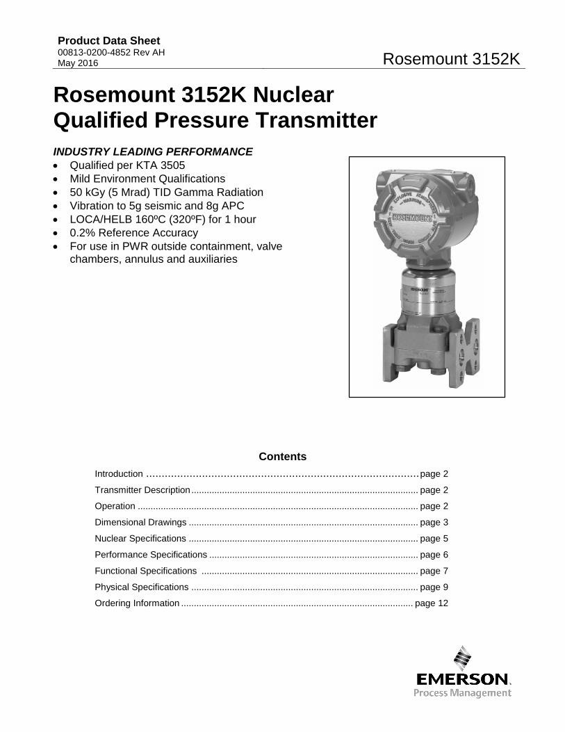
Rosemount 3152K Nuclear Qualified Pressure Transmitter INDUSTRY LEADING PERFORMANCE • Qualified per KTA 3505 • Mild Environment Qualifications • 50 kGy (5 Mrad) TID Gamma Radiation • Vibration to 5g seismic and 8g APC • LOCA/HELB 160ºC (320ºF) for 1 hour • 0.2% Reference Accuracy • For use in PWR outside containment, valve
chambers, annulus and auxiliaries
Contents Introduction ........................................................................................ page 2
Transmitter Description ......................................................................................... page 2
Operation .............................................................................................................. page 2
Dimensional Drawings .......................................................................................... page 3
Nuclear Specifications .......................................................................................... page 5
Performance Specifications .................................................................................. page 6
Functional Specifications ..................................................................................... page 7
Physical Specifications ......................................................................................... page 9
Ordering Information ........................................................................................... page 12
Rosemount 3152K Product Data Sheet
00813-0200-4852 Rev AH May 2016
2
Results Driven by Proven Measurement
Introduction
Rosemount 3152K Nuclear Pressure Transmitters are designed for precision pressure measurements in nuclear applications which require reliable performance and safety over an extended service life. These transmitters were qualified per KTA 3505 at radiation levels of 50 kGy TID gamma radiation, vibration levels up to 5g seismic and 8g APC, and for steam pressure/temperature performance. Stringent quality control during the manufacturing process includes traceability of pressure-retaining parts, special nuclear cleaning, and hydrostatic testing.
Applications
Intended areas of installation in Pressurized Water Reactors (PWR) are outside containment, valve chambers, annulus and auxiliaries.
Transmitter Description
Rosemount 3152K Transmitters are similar in construction and performance to the proven Rosemount 3051 Transmitters. Units are available
in absolute (AP), gauge (GP), and differential (DP) configurations, with 6 pressure range options.
Direct electronic sensing with the completely sealed coplanar capacitance sensing element (see Figure 1) eliminates mechanical force transfer and problems associated with shock and vibration. Installation and commissioning are simplified by compact design, 2-wire system compatibility, and non-interacting external span and zero adjustments for standard calibrations. Wiring terminals and electronics are in separate compartments, so the electronics remain sealed during installation.
Operation
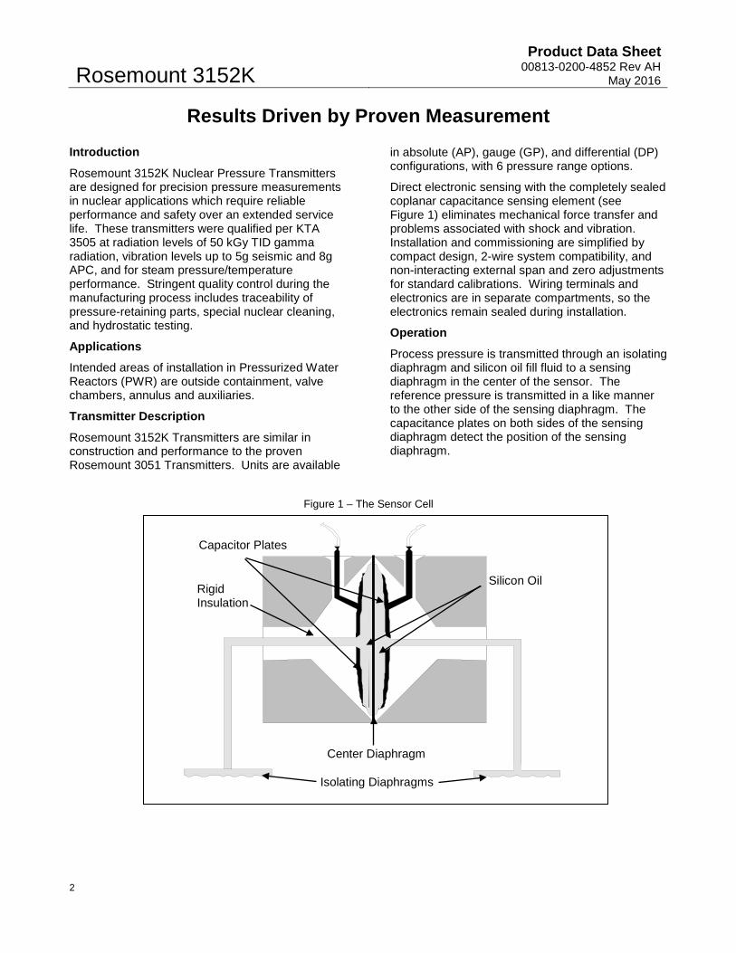
Process pressure is transmitted through an isolating diaphragm and silicon oil fill fluid to a sensing diaphragm in the center of the sensor. The reference pressure is transmitted in a like manner to the other side of the sensing diaphragm. The capacitance plates on both sides of the sensing diaphragm detect the position of the sensing diaphragm.
Figure 1 – The Sensor Cell
Capacitor Plates
Silicon Oil
Isolating Diaphragms
Center Diaphragm
Rigid Insulation
Product Data Sheet 00813-0200-4852 Rev AH May 2016
Rosemount 3152K
3
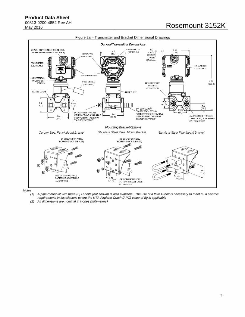
Figure 2a – Transmitter and Bracket Dimensional Drawings
Notes (1) A pipe-mount kit with three (3) U-bolts (not shown) is also available. The use of a third U-bolt is necessary to meet KTA seismic
requirements in installations where the KTA Airplane Crash (APC) value of 8g is applicable (2) All dimensions are nominal in inches (millimeters)
(1)
Rosemount 3152K Product Data Sheet
00813-0200-4852 Rev AH May 2016
4
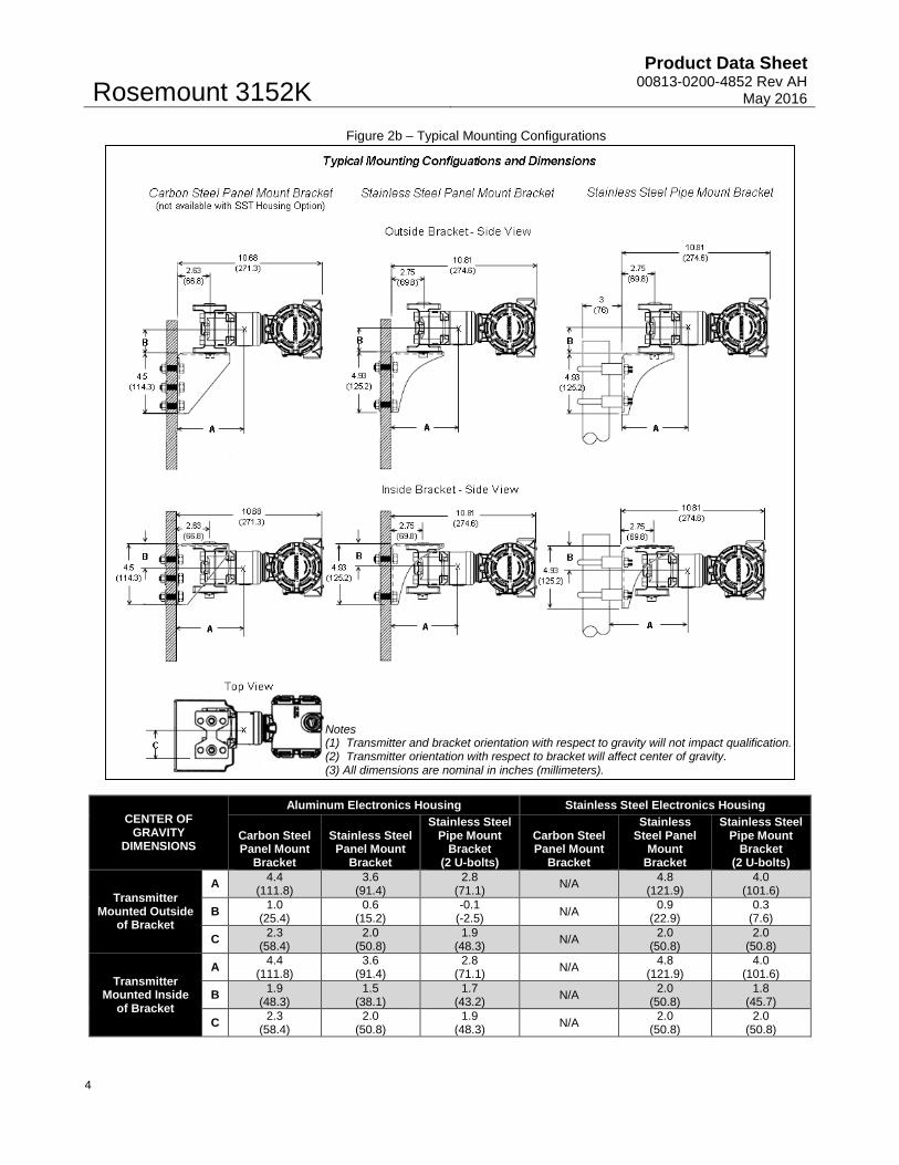
Figure 2b – Typical Mounting Configurations
CENTER OF GRAVITY
DIMENSIONS
Aluminum Electronics Housing Stainless Steel Electronics Housing
Carbon Steel Panel Mount
Bracket
Stainless Steel Panel Mount
Bracket
Stainless Steel Pipe Mount
Bracket (2 U-bolts)
Carbon Steel Panel Mount
Bracket
Stainless Steel Panel
Mount Bracket
Stainless Steel Pipe Mount
Bracket (2 U-bolts)
Transmitter Mounted Outside
of Bracket
A 4.4 (111.8)
3.6 (91.4)
2.8 (71.1) N/A 4.8
(121.9) 4.0
(101.6)
B 1.0 (25.4)
0.6 (15.2)
-0.1 (-2.5) N/A 0.9
(22.9) 0.3
(7.6)
C 2.3 (58.4)
2.0 (50.8)
1.9 (48.3) N/A 2.0
(50.8) 2.0
(50.8)
Transmitter Mounted Inside
of Bracket
A 4.4 (111.8)
3.6 (91.4)
2.8 (71.1) N/A 4.8
(121.9) 4.0
(101.6)
B 1.9 (48.3)
1.5 (38.1)
1.7 (43.2) N/A 2.0
(50.8) 1.8
(45.7)
C 2.3 (58.4)
2.0 (50.8)
1.9 (48.3) N/A 2.0
(50.8) 2.0
(50.8)
Notes (1) Transmitter and bracket orientation with respect to gravity will not impact qualification. (2) Transmitter orientation with respect to bracket will affect center of gravity. (3) All dimensions are nominal in inches (millimeters).
Product Data Sheet 00813-0200-4852 Rev AH May 2016
Rosemount 3152K
5
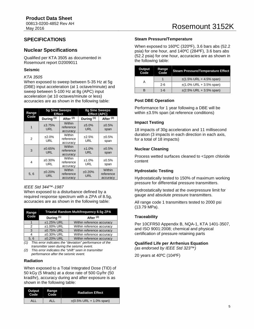
SPECIFICATIONS Nuclear Specifications Qualified per KTA 3505 as documented in Rosemount report D2009011
Seismic
KTA 3505 When exposed to sweep between 5-35 Hz at 5g (DBE) input acceleration (at 1 octave/minute) and sweep between 5-100 Hz at 8g (APC) input acceleration (at 10 octaves/minute or less) accuracies are as shown in the following table:
Range Code
5g Sine Sweeps Effect
8g Sine Sweeps Effect (APC)
During (1) After (2) During (1) After (2)
1 ±3.75% URL
Within reference accuracy
±5.0% URL
±0.5% span
2 ±2.0% URL
Within reference accuracy
±2.5% URL
±0.5% span
3 ±0.65% URL
Within reference accuracy
±1.0% URL
±0.5% span
4 ±0.30% URL
Within reference accuracy
±1.0% URL
±0.5% span
5, 6 ±0.20% URL
Within reference accuracy
±0.20% URL
Within reference accuracy
IEEE Std 344™-1987 When exposed to a disturbance defined by a required response spectrum with a ZPA of 8.5g, accuracies are as shown in the following table:
Range Code
Triaxial Random Multifrequency 8.5g ZPA
During (1) After (2) 1 ±1.25% URL Within reference accuracy 2 ±1.00% URL Within reference accuracy 3 ±0.75% URL Within reference accuracy 4 ±0.30% URL Within reference accuracy
5, 6 ±0.20% URL Within reference accuracy (1) This error indicates the “deviation” performance of the
transmitter seen during the seismic event. (2) This error indicates the “shift” seen in transmitter
performance after the seismic event.
Radiation
When exposed to a Total Integrated Dose (TID) of 50 kGy (5 Mrads) at a dose rate of 500 Gy/hr (50 krad/hr), accuracy during and after exposure is as shown in the following table:
Output Code
Range Code Radiation Effect
ALL ALL ±(0.5% URL + 1.0% span)
Steam Pressure/Temperature
When exposed to 160ºC (320ºF), 3.6 bars abs (52.2 psia) for one hour, and 140ºC (284ºF), 3.6 bars abs (52.2 psia) for one hour, accuracies are as shown in the following table:
Output Code
Range Code Steam Pressure/Temperature Effect
A 1 ±(1.5% URL + 4.5% span)
2-6 ±(1.0% URL + 3.5% span)
B 1-6 ±(2.5% URL + 3.5% span)
Post DBE Operation
Performance for 1 year following a DBE will be within ±3.5% span (at reference conditions)
Impact Testing
18 impacts of 30g acceleration and 11 millisecond duration (3 impacts in each direction in each axis, for a total of 18 impacts)
Nuclear Cleaning
Process wetted surfaces cleaned to <1ppm chloride content
Hydrostatic Testing
Hydrostatically tested to 150% of maximum working pressure for differential pressure transmitters.
Hydrostatically tested at the overpressure limit for gauge and absolute pressure transmitters.
All range code 1 transmitters tested to 2000 psi (13.79 MPa).
Traceability
Per 10CFR50 Appendix B, NQA-1, KTA 1401-3507, and ISO 9001:2008; chemical and physical certification of pressure retaining parts
Qualified Life per Arrhenius Equation (as endorsed by IEEE Std 323™)
20 years at 40ºC (104ºF)
Rosemount 3152K Product Data Sheet
00813-0200-4852 Rev AH May 2016
6
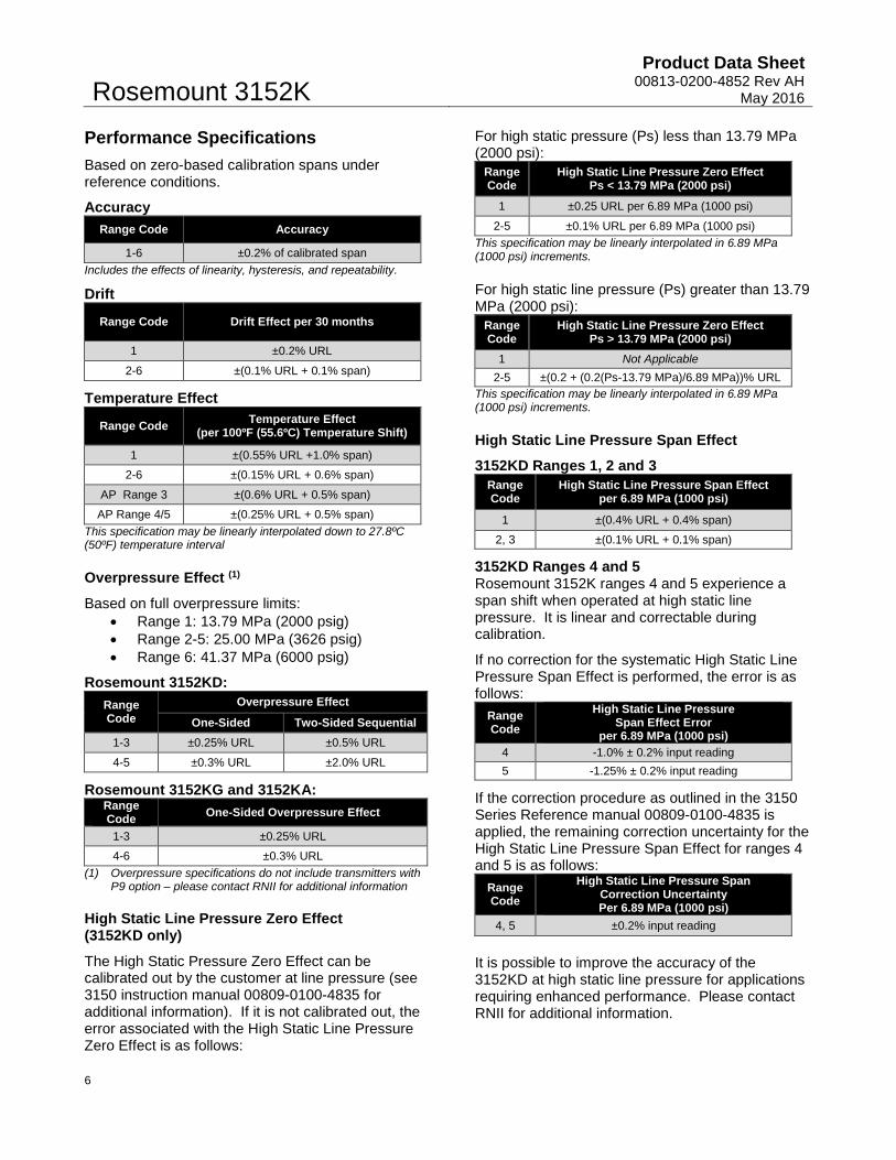
Performance Specifications Based on zero-based calibration spans under reference conditions.
Accuracy Range Code Accuracy
1-6 ±0.2% of calibrated span Includes the effects of linearity, hysteresis, and repeatability.
Drift
Range Code Drift Effect per 30 months
1 ±0.2% URL
2-6 ±(0.1% URL + 0.1% span)
Temperature Effect
Range Code Temperature Effect (per 100ºF (55.6ºC) Temperature Shift)
1 ±(0.55% URL +1.0% span)
2-6 ±(0.15% URL + 0.6% span)
AP Range 3 ±(0.6% URL + 0.5% span)
AP Range 4/5 ±(0.25% URL + 0.5% span) This specification may be linearly interpolated down to 27.8ºC (50ºF) temperature interval
Overpressure Effect (1)
Based on full overpressure limits: • Range 1: 13.79 MPa (2000 psig) • Range 2-5: 25.00 MPa (3626 psig) • Range 6: 41.37 MPa (6000 psig)
Rosemount 3152KD: Range Code
Overpressure Effect
One-Sided Two-Sided Sequential 1-3 ±0.25% URL ±0.5% URL
4-5 ±0.3% URL ±2.0% URL
Rosemount 3152KG and 3152KA: Range Code One-Sided Overpressure Effect
1-3 ±0.25% URL
4-6 ±0.3% URL (1) Overpressure specifications do not include transmitters with
P9 option – please contact RNII for additional information
High Static Line Pressure Zero Effect (3152KD only)
The High Static Pressure Zero Effect can be calibrated out by the customer at line pressure (see 3150 instruction manual 00809-0100-4835 for additional information). If it is not calibrated out, the error associated with the High Static Line Pressure Zero Effect is as follows:
For high static pressure (Ps) less than 13.79 MPa (2000 psi):
Range Code
High Static Line Pressure Zero Effect Ps < 13.79 MPa (2000 psi)
1 ±0.25 URL per 6.89 MPa (1000 psi)
2-5 ±0.1% URL per 6.89 MPa (1000 psi) This specification may be linearly interpolated in 6.89 MPa (1000 psi) increments.
For high static line pressure (Ps) greater than 13.79 MPa (2000 psi):
Range Code
High Static Line Pressure Zero Effect Ps > 13.79 MPa (2000 psi)
1 Not Applicable 2-5 ±(0.2 + (0.2(Ps-13.79 MPa)/6.89 MPa))% URL
This specification may be linearly interpolated in 6.89 MPa (1000 psi) increments.
High Static Line Pressure Span Effect
3152KD Ranges 1, 2 and 3 Range Code
High Static Line Pressure Span Effect per 6.89 MPa (1000 psi)
1 ±(0.4% URL + 0.4% span)
2, 3 ±(0.1% URL + 0.1% span)
3152KD Ranges 4 and 5 Rosemount 3152K ranges 4 and 5 experience a span shift when operated at high static line pressure. It is linear and correctable during calibration.
If no correction for the systematic High Static Line Pressure Span Effect is performed, the error is as follows:
Range Code
High Static Line Pressure Span Effect Error
per 6.89 MPa (1000 psi) 4 -1.0% ± 0.2% input reading 5 -1.25% ± 0.2% input reading
If the correction procedure as outlined in the 3150 Series Reference manual 00809-0100-4835 is applied, the remaining correction uncertainty for the High Static Line Pressure Span Effect for ranges 4 and 5 is as follows:
Range Code
High Static Line Pressure Span Correction Uncertainty Per 6.89 MPa (1000 psi)
4, 5 ±0.2% input reading
It is possible to improve the accuracy of the 3152KD at high static line pressure for applications requiring enhanced performance. Please contact RNII for additional information.
Product Data Sheet 00813-0200-4852 Rev AH May 2016
Rosemount 3152K
7
Power Supply Effect
Less than 0.005% of span / volt
Load Effect
No load effect other than the change in voltage supplied to the transmitter
Electromagnetic Compatibility
Meets the specifications defined in the following standards:
• EN 61000-6-2 and EN61000-6-4 (see Rosemount report D2010005)
• EN 61326-1 and EN61326-2-3 (see Rosemount report D2008005)
Transient Protection (Option T1)
Designed in accordance with IEEE C62.41.2-2002: Location Category B 6kV crest (0.5 microseconds – 100 kHz) 3kA crest (8 x 20 microseconds) 6 kV crest (1.2 x 50 microseconds)
Mounting Position Effect
No span effect; zero shift of up to 0.37 kPa (1.5 inH2O) which can be calibrated out.
Functional Specifications Service
Liquid, gas, vapor
Output
4-20 mA
Power Supply
Maximum supply voltage • 50 VDC
Maximum allowable supply voltage ripple • less than 1 volt peak-to-peak ripple for
ripple frequency less than or equal to 120 Hz
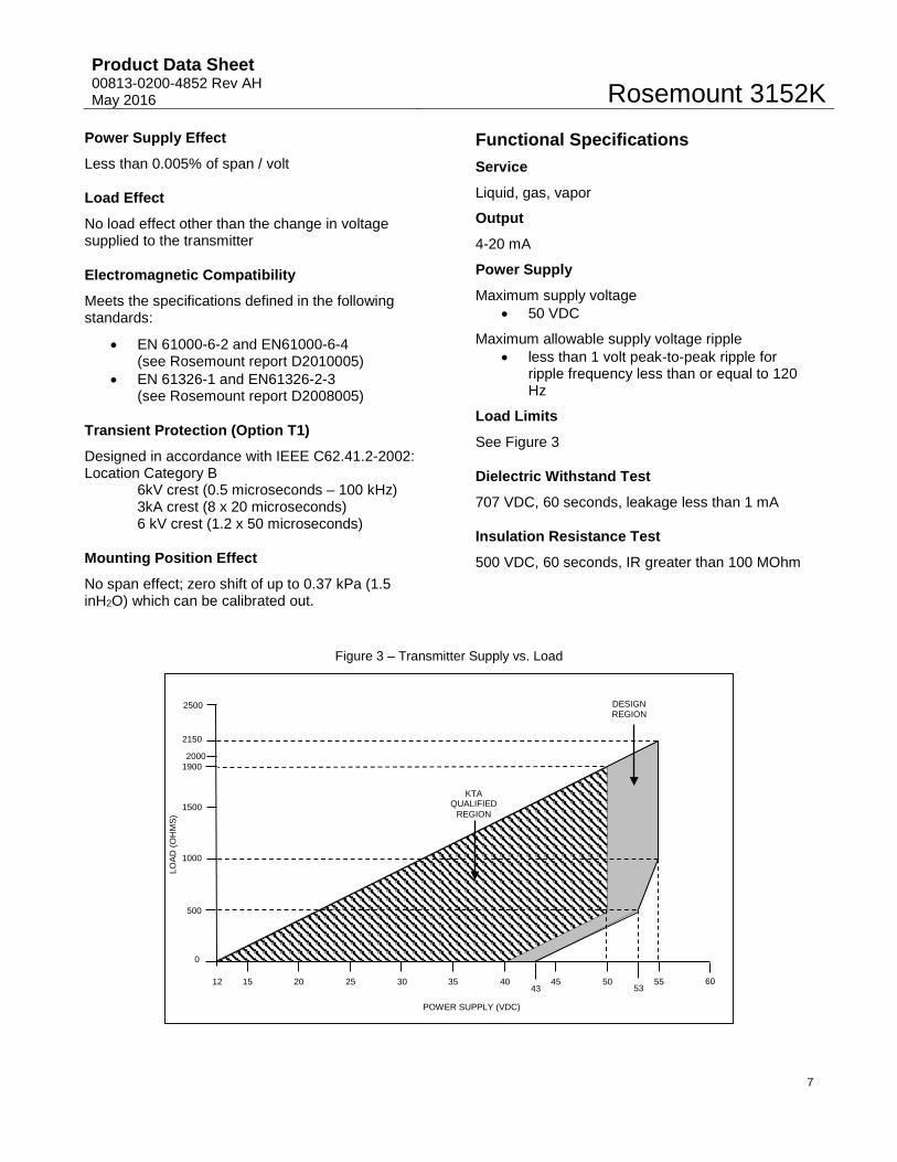
Load Limits
See Figure 3
Dielectric Withstand Test
707 VDC, 60 seconds, leakage less than 1 mA
Insulation Resistance Test
500 VDC, 60 seconds, IR greater than 100 MOhm
Figure 3 – Transmitter Supply vs. Load
2150
POWER SUPPLY (VDC)
2500
1500
500
12
1000
20 25 30 35 40 45 50
15
55
KTA QUALIFIED
REGION
DESIGN REGION
LOAD
(OH
MS)
53 60
43
0
1900 2000
Rosemount 3152K Product Data Sheet
00813-0200-4852 Rev AH May 2016
8
Span and Zero Adjustments
External adjust; non-interacting for standard adjustments
Zero Elevation, Zero Suppression
Maximum Zero Elevation Zero is adjustable to the Lower Range Limit (LRL)
Maximum Zero Suppression Zero is adjustable to 90% of the Upper Range Limit (URL) (80% for Range 1)
Range Down
10:1 (5:1 for Range 1)
Response Time
Time constant (63.2%) at 37.8ºC (100ºF)
Output Code A
Range Code Fixed Time Response (Max)
DP / GP AP 1 0.40 sec N/A
2 0.20 sec N/A
3 0.20 sec 0.20 sec
4-6 0.20 sec 0.20 sec
Output Code B (Continuously Adjustable Damping)
Range Code Minimum Time Response in the Max Damping Position
ALL 1.20 sec Note: In the Minimum Damping Position, the values for Fixed Time Response apply.
Temperature Limits
Normal Operating Limits: 4.4ºC to 93.3ºC (40ºF to 200ºF)
Qualified Storage Limits: -40.0ºC to 48.9ºC (-40ºF to 120ºF)
Humidity Limits
0 to 100% relative humidity
Enclosure Rating
NEMA 4X (IP 66)
Volumetric Displacement
Less than 0.082 cm3 (less than 0.005 in3)
Turn-On Time
2 seconds maximum
Maximum Working Pressure
Larger of Static Pressure Limit or Upper Range Limit (URL)
Pressure Ranges
Adjustable within the range shown; upper range limit (URL) is the highest pressure shown
Rosemount 3152KD and 3152KG Range Code Pressure Range
1 0-1.25 kPa to 0-6.23 kPa (0-5 to 0-25 inH2O)
2 0-6.23 kPa to 0-62.3 kPa (0-25 to 0-250 inH2O)
3 0-24.9 kPa to 0-249 kPa (0-100 to 0-1000 inH2O)
4 0-206.8 kPa to 0-2068 kPa (0-30 to 0-300 psig)
5 0-1379 kPa to 0-13.79 MPa (0-200 to 0-2000 psig)
6 0-2758 kPa to 0-27.58 MPa (0-400 to 0-4000 psig) Range 6 not available on 3152KD
Rosemount 3152KA (1)
Range Code Pressure Range
3 0-24.9 kPa to 0-249 kPa (0-100 to 0-1000 inH2O abs)
4 0-206.8 kPa to 0-2068 kPa (0-30 to 0-300 psia)
5 0-1379 kPa to 0-13.79 MPa (0-200 to 0-2000 psia)
6 0-2758 kPa to 0-27.58 MPa (0-400 to 0-4000 psia)
(1) Extended operation below 3.5 kPa absolute pressure (0.5 psia) is not recommended.
Static Pressure Limits (3152KD only) Range Code Static Pressure Limit
1 3.45 kPa to 13.79 MPa (0.5 psia to 2000 psig)
2-5 3.45 kPa to 25.00 MPa (0.5 psia to 3626 psig)
Overpressure Limits Range Code Overpressure Limit
1 13.79 MPa (2000 psig)
2-5 25.00 MPa (3626 psig) [31.03 MPa (4500 psig) with P9 option]
6 43.36 MPa (6000 psig)
Burst Pressure
Product Data Sheet 00813-0200-4852 Rev AH May 2016
Rosemount 3152K
9
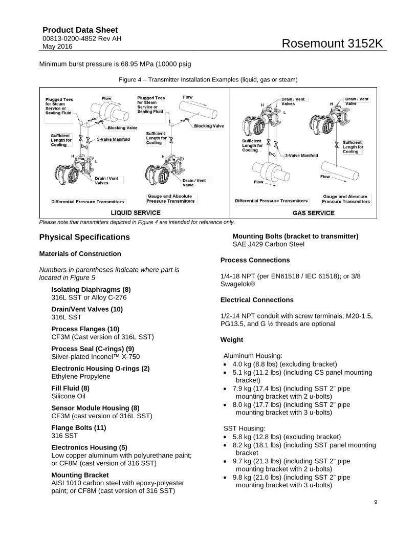
Minimum burst pressure is 68.95 MPa (10000 psig
Figure 4 – Transmitter Installation Examples (liquid, gas or steam)
Please note that transmitters depicted in Figure 4 are intended for reference only.
Physical Specifications
Materials of Construction
Numbers in parentheses indicate where part is located in Figure 5
Isolating Diaphragms (8) 316L SST or Alloy C-276
Drain/Vent Valves (10) 316L SST
Process Flanges (10) CF3M (Cast version of 316L SST)
Process Seal (C-rings) (9) Silver-plated Inconel™ X-750
Electronic Housing O-rings (2) Ethylene Propylene
Fill Fluid (8) Silicone Oil
Sensor Module Housing (8) CF3M (cast version of 316L SST)
Flange Bolts (11) 316 SST
Electronics Housing (5) Low copper aluminum with polyurethane paint; or CF8M (cast version of 316 SST)
Mounting Bracket AISI 1010 carbon steel with epoxy-polyester paint; or CF8M (cast version of 316 SST)
Mounting Bolts (bracket to transmitter) SAE J429 Carbon Steel
Process Connections
1/4-18 NPT (per EN61518 / IEC 61518); or 3/8 Swagelok®
Electrical Connections
1/2-14 NPT conduit with screw terminals; M20-1.5, PG13.5, and G ½ threads are optional
Weight
Aluminum Housing: • 4.0 kg (8.8 lbs) (excluding bracket) • 5.1 kg (11.2 lbs) (including CS panel mounting
bracket) • 7.9 kg (17.4 lbs) (including SST 2” pipe
mounting bracket with 2 u-bolts) • 8.0 kg (17.7 lbs) (including SST 2” pipe
mounting bracket with 3 u-bolts)
SST Housing: • 5.8 kg (12.8 lbs) (excluding bracket) • 8.2 kg (18.1 lbs) (including SST panel mounting
bracket • 9.7 kg (21.3 lbs) (including SST 2” pipe
mounting bracket with 2 u-bolts) • 9.8 kg (21.6 lbs) (including SST 2” pipe
mounting bracket with 3 u-bolts)
Rosemount 3152K Product Data Sheet
00813-0200-4852 Rev AH May 2016
10
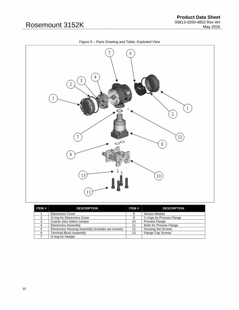
Figure 5 – Parts Drawing and Table, Exploded View
ITEM # DESCRIPTION ITEM # DESCRIPTION
1 Electronics Cover 8 Sensor Module 2 O-ring for Electronics Cover 9 C-rings for Process Flange 3 Coarse Zero Select Jumper 10 Process Flange 4 Electronics Assembly 11 Bolts for Process Flange 5 Electronics Housing Assembly (includes set screws) 12 Housing Set Screws 6 Terminal Block Assembly 13 Flange Cap Screws 7 O-ring for Header
Product Data Sheet 00813-0200-4852 Rev AH May 2016
Rosemount 3152K
11
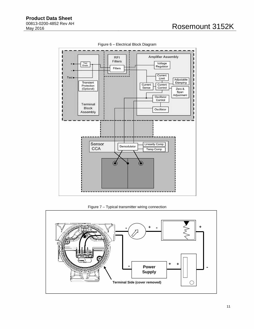
Figure 6 – Electrical Block Diagram
Figure 7 – Typical transmitter wiring connection
Terminal Side (cover removed)
-
+ - +
+ + - Power Supply
-
Rosemount 3152K Product Data Sheet
00813-0200-4852 Rev AH May 2016
12
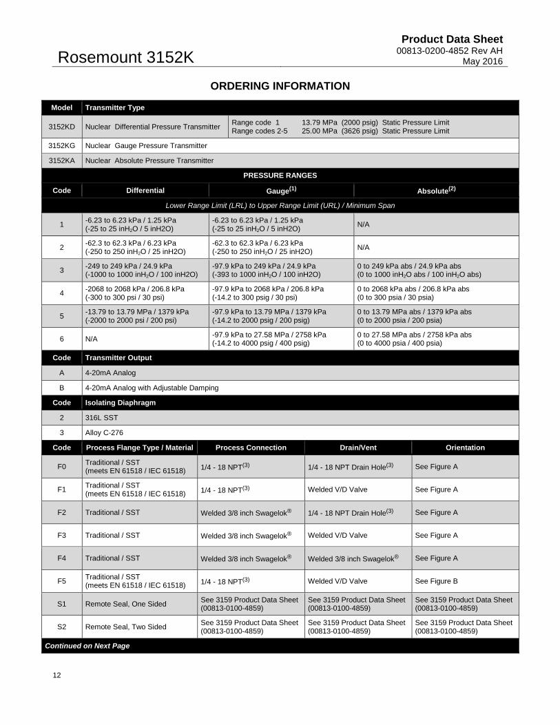
ORDERING INFORMATION
Model Transmitter Type
3152KD Nuclear Differential Pressure Transmitter Range code 1 13.79 MPa (2000 psig) Static Pressure Limit Range codes 2-5 25.00 MPa (3626 psig) Static Pressure Limit
3152KG Nuclear Gauge Pressure Transmitter
3152KA Nuclear Absolute Pressure Transmitter
PRESSURE RANGES
Code Differential Gauge(1) Absolute(2)
Lower Range Limit (LRL) to Upper Range Limit (URL) / Minimum Span
1 -6.23 to 6.23 kPa / 1.25 kPa (-25 to 25 inH2O / 5 inH2O)
-6.23 to 6.23 kPa / 1.25 kPa (-25 to 25 inH2O / 5 inH2O) N/A
2 -62.3 to 62.3 kPa / 6.23 kPa (-250 to 250 inH2O / 25 inH2O)
-62.3 to 62.3 kPa / 6.23 kPa (-250 to 250 inH2O / 25 inH2O) N/A
3 -249 to 249 kPa / 24.9 kPa (-1000 to 1000 inH2O / 100 inH2O)
-97.9 kPa to 249 kPa / 24.9 kPa (-393 to 1000 inH2O / 100 inH2O)
0 to 249 kPa abs / 24.9 kPa abs (0 to 1000 inH2O abs / 100 inH2O abs)
4 -2068 to 2068 kPa / 206.8 kPa (-300 to 300 psi / 30 psi)
-97.9 kPa to 2068 kPa / 206.8 kPa (-14.2 to 300 psig / 30 psi)
0 to 2068 kPa abs / 206.8 kPa abs (0 to 300 psia / 30 psia)
5 -13.79 to 13.79 MPa / 1379 kPa (-2000 to 2000 psi / 200 psi)
-97.9 kPa to 13.79 MPa / 1379 kPa (-14.2 to 2000 psig / 200 psig)
0 to 13.79 MPa abs / 1379 kPa abs (0 to 2000 psia / 200 psia)
6 N/A -97.9 kPa to 27.58 MPa / 2758 kPa (-14.2 to 4000 psig / 400 psig)
0 to 27.58 MPa abs / 2758 kPa abs (0 to 4000 psia / 400 psia)
Code Transmitter Output
A 4-20mA Analog
B 4-20mA Analog with Adjustable Damping
Code Isolating Diaphragm
2 316L SST
3 Alloy C-276
Code Process Flange Type / Material Process Connection Drain/Vent Orientation
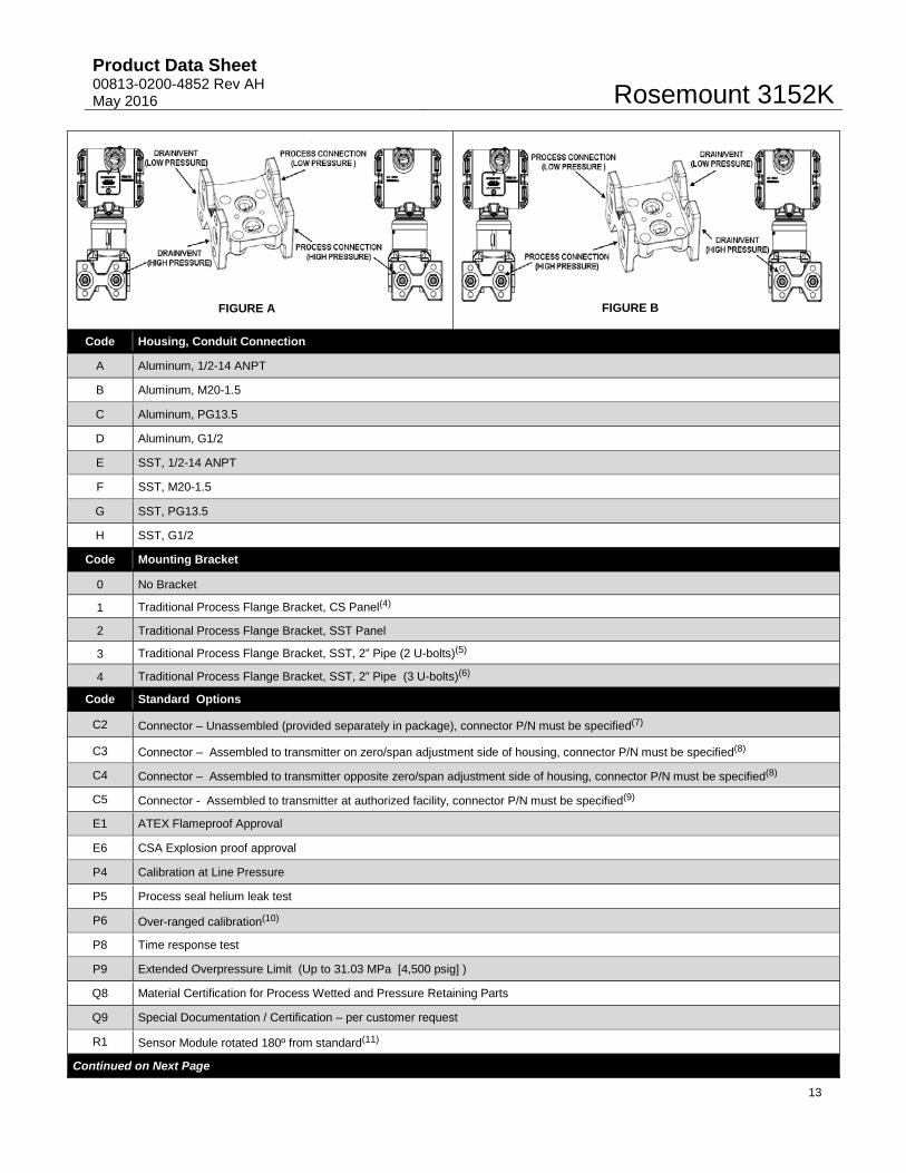
F0 Traditional / SST (meets EN 61518 / IEC 61518) 1/4 - 18 NPT(3) 1/4 - 18 NPT Drain Hole(3) See Figure A
F1 Traditional / SST (meets EN 61518 / IEC 61518) 1/4 - 18 NPT(3) Welded V/D Valve See Figure A
F2 Traditional / SST Welded 3/8 inch Swagelok® 1/4 - 18 NPT Drain Hole(3) See Figure A
F3 Traditional / SST Welded 3/8 inch Swagelok® Welded V/D Valve See Figure A
F4 Traditional / SST Welded 3/8 inch Swagelok® Welded 3/8 inch Swagelok® See Figure A
F5 Traditional / SST (meets EN 61518 / IEC 61518) 1/4 - 18 NPT(3) Welded V/D Valve See Figure B
S1 Remote Seal, One Sided See 3159 Product Data Sheet (00813-0100-4859)
See 3159 Product Data Sheet (00813-0100-4859)
See 3159 Product Data Sheet (00813-0100-4859)
S2 Remote Seal, Two Sided See 3159 Product Data Sheet (00813-0100-4859)
See 3159 Product Data Sheet (00813-0100-4859)
See 3159 Product Data Sheet (00813-0100-4859)
Continued on Next Page
Product Data Sheet 00813-0200-4852 Rev AH May 2016
Rosemount 3152K
13
Code Housing, Conduit Connection
A Aluminum, 1/2-14 ANPT
B Aluminum, M20-1.5
C Aluminum, PG13.5
D Aluminum, G1/2
E SST, 1/2-14 ANPT
F SST, M20-1.5
G SST, PG13.5
H SST, G1/2
Code Mounting Bracket
0 No Bracket
1 Traditional Process Flange Bracket, CS Panel(4)
2 Traditional Process Flange Bracket, SST Panel
3 Traditional Process Flange Bracket, SST, 2” Pipe (2 U-bolts)(5)
4 Traditional Process Flange Bracket, SST, 2” Pipe (3 U-bolts)(6)
Code Standard Options
C2 Connector – Unassembled (provided separately in package), connector P/N must be specified(7)
C3 Connector – Assembled to transmitter on zero/span adjustment side of housing, connector P/N must be specified(8)
C4 Connector – Assembled to transmitter opposite zero/span adjustment side of housing, connector P/N must be specified(8)
C5 Connector - Assembled to transmitter at authorized facility, connector P/N must be specified(9)
E1 ATEX Flameproof Approval
E6 CSA Explosion proof approval
P4 Calibration at Line Pressure
P5 Process seal helium leak test
P6 Over-ranged calibration(10)
P8 Time response test
P9 Extended Overpressure Limit (Up to 31.03 MPa [4,500 psig] )
Q8 Material Certification for Process Wetted and Pressure Retaining Parts
Q9 Special Documentation / Certification – per customer request
R1 Sensor Module rotated 180º from standard(11)
Continued on Next Page
FIGURE A FIGURE B
Rosemount 3152K Product Data Sheet
00813-0200-4852 Rev AH May 2016
14
(1) 3152KG LRL varies with atmospheric pressure. (2) Extended operation below 3.5 kPa absolute pressure (0.5 psia) is not recommended. (3) Customer assumes responsibility for qualifying interfaces on these options. (4) Not available with SST housing options. (5) The pipe mount kit provided with mounting bracket option code “3” contains two u-bolts and is qualified for DBE seismic events up to
5g per KTA 3505. (6) The pipe mount kit provided with mounting bracket option code “4” contains three u-bolts and is qualified for Airplane Crash (APC)
seismic events up to 8g per KTA 3505. (7) Qualification of the connector installation and instrument/connector interface is the responsibility of the end user. (8) Installation will be performed at the Rosemount Nuclear factory. Certification of the connector installation and instrument/connector
interface will be provided by Rosemount Nuclear. (9) Installation of the connector will be performed under the applicable Emerson QA program and performed per approved installation
procedures. Certification of the connector installation and instrument/connector interface will be provided by the factory performing the installation
(10) Over-range limit varies by pressure range. Please contact RNII for details. (11) The R1 and R4 options cannot be used together on a single transmitter.
R4 Electronics Housing rotated 180º from standard(11)
T1 Transient Protection
V5 External Ground Screw Kit
W1 Additional Customer Tagging Information – Permanent Tag attached to electronics housing (see Figure 2)
W2 Additional Customer Tagging Information – Wire-on Tag attached to nameplate (see Figure 2)
Typical Model Number: 3152K D 2 A 2 F0 A 0 C3 W1
Product Data Sheet 00813-0200-4852 Rev AH May 2016
Rosemount 3152K
15
Standard Accessories
One instruction manual is included with each shipment.
Caibration
Transmitters are factory calibrated to the customer’s specified range. If calibration is not specified, transmitters are calibrated at maximum range (0 to URL). Calibration is performed at ambient temperature and atmospheric pressure.
Additional Customer Tagging Information
Additional tagging is optional and will be provided when either option W1 or W2 is included in the model number. All tags are SST. The transmitter will be tagged in accordance with customer requirements (within space limitations defined below).
Permanent Tag (W1)
Wire-on Tag (W2)
Nominal Character Height
2.54 mm (0.10 in)
4.76 mm (0.188 in)
Maximum Number of Lines 4 4
Maximum Characters per Line 24 20
Special Options
Please Contact Rosemount Nuclear Instruments, Inc for special transmitter needs.
Spare Parts
A spare part list for the Rosemount 3152K pressure transmitter is located within the Rosemount 3150 Series Reference Manual 00809-0100-4835.
Transportation and Storage
During transportation and storage, transmitters shall be transported only in their original packaging supplied by Rosemount Nuclear.
Documentation
Certifications
Certification of compliance will be provided for each Rosemount 3152K Pressure Transmitter for nuclear qualification, accuracy, special cleaning, hydrostatic testing, and traceability. Chemical and physical reports and identification of pressure-retaining parts will be on file at Rosemount Nuclear Instruments Inc.
Revision Control
As-built drawing and part number revisions of baseline qualification hardware are provided in RNII Document EIF-3152-EPR-01.
The evolution of important drawings, part numbers, manufacturing tests and inspection procedures associated with Rosemount 3152K transmitters is documented in Reference File RF-3152-EPR-01. The reference file is maintained in accordance with RNII’s documented quality system and is intended to satisfy the requirements of “Reference File” as defined by RCC-E and “Document Catalogue” as defined by KTA

Rosemount 3152K Product Data Sheet
00813-0200-4852 Rev AH May 2016
16

Product Data Sheet 00813-0200-4852 Rev AH May 2016
Rosemount 3152K
17
Page Intentionally Left Blank

Rosemount 3152K Product Data Sheet
00813-0200-4852 Rev AH May 2016
18
Page Intentionally Left Blank
Product Data Sheet 00813-0200-4852 Rev AH May 2016
Rosemount 3152K
19
REVISIONS Changes from Rev AG to Rev AH
Page (Old) Page (New) Changes
Throughout Throughout Update document revision and implementation date.
6 6 Revised accuracy specification for pressure range 6 transmitters from ±0.25% of calibrated span to ±0.2% of calibrated span.
8 8 Revised response time specification for AP pressure range 3 transmitters with output code A from 0.25 sec to 0.20 sec.
Rosemount 3152K Product Data Sheet
00813-0200-4852 Rev AH May 2016
Standard Terms and Conditions of Sale can be found at: www.Emerson.com/en-us/pages/Terms-of-Use.aspx The Emerson logo is a trademark and service mark of Emerson Electric Co. Coplanar, Rosemount, and Rosemount logotype are trademarks of Emerson Process Management. Swagelok is a registered trademark of Swagelok Co. Std 323 and Std 344 are registered trademarks of IEEE. Inconel is a registered trademark of International Nickel Company. All other marks are the property of their respective owners. © 2016 Emerson Process Management. All rights reserved. Global Headquarters Emerson Process Management Rosemount Nuclear Instruments, Inc. 8200 Market Blvd. Chanhassen, MN 55137, USA P +1 952 949-5210 F +1 952 949-5201 E [email protected]
Rosemount Nuclear Instruments, Inc. satisfies all obligations coming from legislation to harmonize product requirements in the European Union.