Embed Size (px)
Citation preview
©2011-2014 Cymbet Corporation • Tel: +1-763-633-1780 • www.cymbet.comDS-72-20 Rev B Page 1 of 15
CBC-EVAL-10
System Features and OverviewCBC-EVAL-10 is a demonstration kit that provides designers a platform to easily develop Energy Harvesting (EH) solutions using the EnerChip CBC3150TM configured to operate in an energy harvesting mode. The kit combines a small solar panel, power management circuit, energy storage, regulated output voltage, and input/output pins for connection to commercially available microcontroller (MCU) and radio boards. A 16-pin CBC51100 module is included, providing the EH functions, battery management, and 100µAh solid state rechargeable energy storage. CBC-EVAL-10 is a practical, low cost realization of an EH-based power system that can provide many years of service without need of battery maintenance.
CBC-EVAL-10 has the following elements:
• Energy harvesting circuitry that matches the impedance of photovoltaic cells to ensure maximum power transfer to system load and on-board energy storage devices
• Solid state energy storage with thousands of charge-discharge cycles available
• Integrated battery management that controls battery charging and discharge cutoff, ensuring maximum service life of on-board storage cells
• Provision for additional energy storage (primary or rechargeable batteries) with switchover control circuit to meet application requirements
• Regulated output voltage with user-configurable voltage settings
• Input/output headers for connection to system components such as radios and microcontrollers
The photovoltaic (PV) panel included in the CBC-EVAL-10 converts ambient light energy into electrical energy, which is fed into the CBC3150 device residing on the CBC51100 module. The CBC3150 performs several important functions:
• Decouples the load impedance from the PV cell impedance to ensure maximum power conversion efficiency from the PV transducer to the energy storage and system load.
• Controls charge voltage and discharge cutoff circuit for maximizing the service life of the EnerChip solid state batteries within the CBC3150 and auxiliary CBC050 energy storage device on the CBC51100 module.
• Manages internal circuitry for switching from PV power to EnerChip (or external battery) power when ambient light level is too low to power the system and/or recharge the energy storage devices.
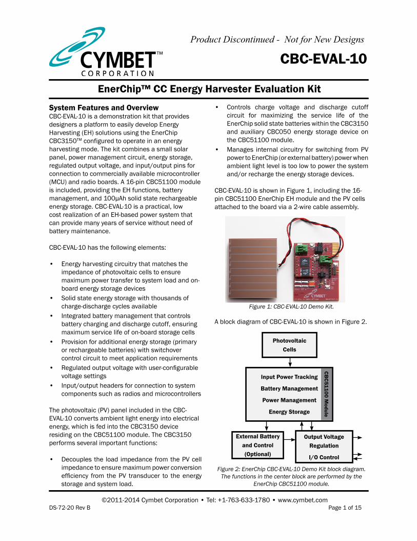
CBC-EVAL-10 is shown in Figure 1, including the 16-pin CBC51100 EnerChip EH module and the PV cells attached to the board via a 2-wire cable assembly.
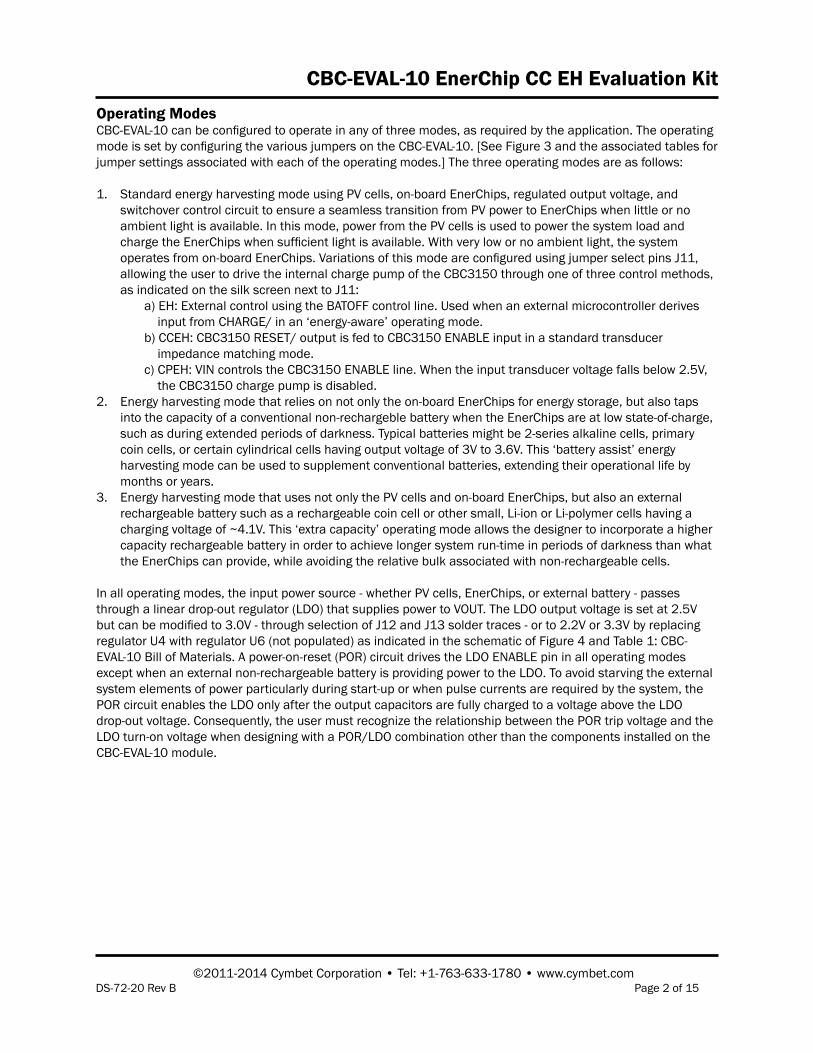
A block diagram of CBC-EVAL-10 is shown in Figure 2.
Figure 1: CBC-EVAL-10 Demo Kit.
EnerChip™ CC Energy Harvester Evaluation Kit
Figure 2: EnerChip CBC-EVAL-10 Demo Kit block diagram. The functions in the center block are performed by the
EnerChip CBC51100 module.
PhotovoltaicCells
Input Power Tracking
Battery Management
Power Management
Energy Storage
Output Voltage Regulation
I/O Control
CBC51100 M
odule
External Batteryand Control (Optional)
Product Discontinued - Not for New Designs
CBC-EVAL-10 EnerChip CC EH Evaluation Kit
©2011-2014 Cymbet Corporation • Tel: +1-763-633-1780 • www.cymbet.comDS-72-20 Rev B Page 2 of 15
Operating ModesCBC-EVAL-10 can be configured to operate in any of three modes, as required by the application. The operating mode is set by configuring the various jumpers on the CBC-EVAL-10. [See Figure 3 and the associated tables for jumper settings associated with each of the operating modes.] The three operating modes are as follows:
1. Standard energy harvesting mode using PV cells, on-board EnerChips, regulated output voltage, and switchover control circuit to ensure a seamless transition from PV power to EnerChips when little or no ambient light is available. In this mode, power from the PV cells is used to power the system load and charge the EnerChips when sufficient light is available. With very low or no ambient light, the system operates from on-board EnerChips. Variations of this mode are configured using jumper select pins J11, allowing the user to drive the internal charge pump of the CBC3150 through one of three control methods, as indicated on the silk screen next to J11:
a) EH: External control using the BATOFF control line. Used when an external microcontroller derives input from CHARGE/ in an ‘energy-aware’ operating mode. b) CCEH: CBC3150 RESET/ output is fed to CBC3150 ENABLE input in a standard transducer impedance matching mode. c) CPEH: VIN controls the CBC3150 ENABLE line. When the input transducer voltage falls below 2.5V, the CBC3150 charge pump is disabled.2. Energy harvesting mode that relies on not only the on-board EnerChips for energy storage, but also taps
into the capacity of a conventional non-rechargeble battery when the EnerChips are at low state-of-charge, such as during extended periods of darkness. Typical batteries might be 2-series alkaline cells, primary coin cells, or certain cylindrical cells having output voltage of 3V to 3.6V. This ‘battery assist’ energy harvesting mode can be used to supplement conventional batteries, extending their operational life by months or years.
3. Energy harvesting mode that uses not only the PV cells and on-board EnerChips, but also an external rechargeable battery such as a rechargeable coin cell or other small, Li-ion or Li-polymer cells having a charging voltage of ~4.1V. This ‘extra capacity’ operating mode allows the designer to incorporate a higher capacity rechargeable battery in order to achieve longer system run-time in periods of darkness than what the EnerChips can provide, while avoiding the relative bulk associated with non-rechargeable cells.
In all operating modes, the input power source - whether PV cells, EnerChips, or external battery - passes through a linear drop-out regulator (LDO) that supplies power to VOUT. The LDO output voltage is set at 2.5V but can be modified to 3.0V - through selection of J12 and J13 solder traces - or to 2.2V or 3.3V by replacing regulator U4 with regulator U6 (not populated) as indicated in the schematic of Figure 4 and Table 1: CBC-EVAL-10 Bill of Materials. A power-on-reset (POR) circuit drives the LDO ENABLE pin in all operating modes except when an external non-rechargeable battery is providing power to the LDO. To avoid starving the external system elements of power particularly during start-up or when pulse currents are required by the system, the POR circuit enables the LDO only after the output capacitors are fully charged to a voltage above the LDO drop-out voltage. Consequently, the user must recognize the relationship between the POR trip voltage and the LDO turn-on voltage when designing with a POR/LDO combination other than the components installed on the CBC-EVAL-10 module.
CBC-EVAL-10 EnerChip CC EH Evaluation Kit
©2011-2014 Cymbet Corporation • Tel: +1-763-633-1780 • www.cymbet.comDS-72-20 Rev B Page 3 of 15
External Control of the CBC-EVAL-10 Energy Harvesting FunctionsIn addition to protecting the EnerChips from being discharged too deeply in low ambient light conditions or abnormally high current load conditions, the CBC3150 power management circuit also ensures that the system load is powered with a smooth power-on transition. The power management circuit has a control line (CHARGE/) for indication to the system controller that the energy harvester is charging the EnerChips. A control line input (BATOFF) is available for the external controller to disable the CBC3150 charge pump. Use of these two control lines is optional.
There are several connectors on CBC-EVAL-10 for connection to target devices to be powered. Either the J9 or J10 connector can be used for low power microcontroller-based systems. In the case of a low power wireless end device, the CBC-EVAL-10 has storage energy for approximately 1000 radio transmissions - depending on protocol used - in no/low ambient light conditions.
Microcontroller-based systems that are powered by the CBC-EVAL-10 should contain firmware that is “Energy Harvesting Aware” and take advantage of the power management status and control signals available on CBC-EVAL-10.
Using Additional EnerChips and External BatteriesThe CBC-EVAL-10 is designed to permit attachment of rechargeable and non-rechargeable batteries whereby the energy harvesting circuitry extends the life of those batteries by operating from (i) PV cell power when suf-ficient light is available, (ii) EnerChips when in an acceptable state-of-charge, and (iii) the external battery when neither of those two conditions exists.
Two classes of external batteries may be attached to the CBC-EVAL-10:1. A primary battery (i.e., non-rechargeable) or series combination of primary batteries may be connected to
header pins J3 only. The acceptable voltage range is 2.7 to 3.6. Commonly used batteries in this category are: A single 3V CR-type or BR-type coin cell (e.g., CR2032, BR2032), or two alkaline cells (e.g., AAA, AA, C, D) connected in series. A single 3.6V thionyl chloride cell may also be used. Contact Cymbet for recommen-dations in selecting a primary battery for your application.
2. A secondary (i.e., rechargeable) battery may be connected to header pins J7 only. The acceptable charging voltage range is 4.0V to 4.2V. The charging source for this battery is the VCHG output pin of the CBC3150 that normally charges the EnerChips to 4.1V. Maximum drive current of this pin is on the order of 1mA. VCHG drive current can be adjusted by populating capacitor C9 (module shipped without a capacitor). See DS-72-03 EnerChip CC CBC3150 Data Sheet for guidelines on sizing the charge pump capacitor. The discharge cutoff voltage is fixed at 3.0V +/- 0.3V. Examples of rechargeable batteries supported by CBC-EVAL-10 are the LiR-type coin cells, including LiR-1220 (~8mAh) and LiR-2032 (~40mAh). The charging rate for these external cells will be a function of available light, to a maximum of 1mA as limited by the CBC3150 charge pump drive current.
To operate the CBC-EVAL-10 board for use with an external battery, configure the header pins as follows:
1. Non-rechargeable (i.e., primary) battery connected to EXT BAT terminal block J3: J1 and J2 - shorted J4, J5, J6 - not shorted J7 - no connection
2. Rechargeable (i.e., secondary) battery connected to header pins J7: J1, J2 - not shorted J3 - no connection J4, J5, and J6 - shorted
CBC-EVAL-10 EnerChip CC EH Evaluation Kit
©2011-2014 Cymbet Corporation • Tel: +1-763-633-1780 • www.cymbet.comDS-72-20 Rev B Page 4 of 15
CONNECTORS
Connector PinNumber Designation
J31 External Primary
Battery Input (+)
2 External Primary Battery Input (-)
Connector Type: Terminal Block
J7
1External
Rechargeable Battery Input (+)
2External
Rechargeable Battery Input (-)
Connector Type: vias
J81 PV Cell Input (+)
2 PV Cell Input (-)
Connector Type: Terminal Block
J9
1 CHARGE/
2 BATOFF
3 No Connection
4 GND
5 VOUT
Connector Type: Vertical SIP
J10
1 BATOFF
2 GND
3 No Connection
4 No Connection
5 VOUT
6 CHARGE/
Connector Type: Right Angle SIP
1
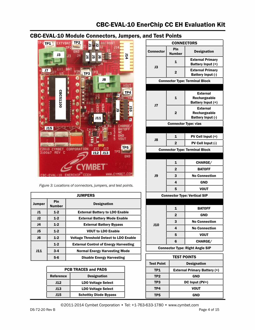
CBC-EVAL-10 Module Connectors, Jumpers, and Test Points
Figure 3: Locations of connectors, jumpers, and test points.
TP1 TP2
TP3
J3
TP5
TP4
J11
J4
J10
J7
J12
J14
J13J6J5
J2
J9
1
J1
J8
CBC51100
JUMPERS
Jumper PinNumber Designation
J1 1-2 External Battery to LDO Enable
J2 1-2 External Battery Mode Enable
J4 1-2 External Battery Bypass
J5 1-2 VOUT to LDO Enable
J6 1-2 Voltage Threshold Detect to LDO Enable
J11
1-2 External Control of Energy Harvesting
3-4 Normal Energy Harvesting Mode
5-6 Disable Energy Harvesting TEST POINTSTest Point Designation
TP1 External Primary Battery (+)
TP2 GND
TP3 DC Input (PV+)
TP4 VOUT
TP5 GND
PCB TRACES and PADSReference Designation
J12 LDO Voltage Select
J13 LDO Voltage Select
J15 Schottky Diode Bypass
J15
CBC-EVAL-10 EnerChip CC EH Evaluation Kit
©2011-2014 Cymbet Corporation • Tel: +1-763-633-1780 • www.cymbet.comDS-72-20 Rev B Page 5 of 15
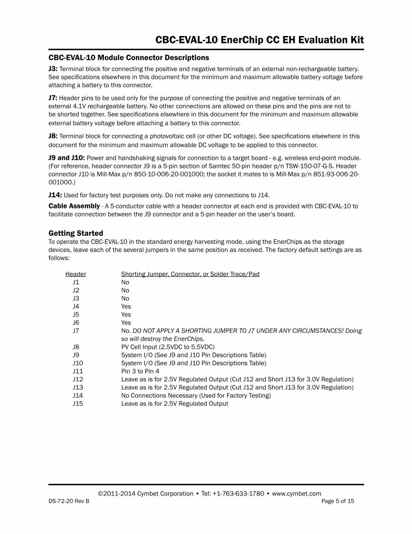
CBC-EVAL-10 Module Connector DescriptionsJ3: Terminal block for connecting the positive and negative terminals of an external non-rechargeable battery. See specifications elsewhere in this document for the minimum and maximum allowable battery voltage before attaching a battery to this connector.
J7: Header pins to be used only for the purpose of connecting the positive and negative terminals of an external 4.1V rechargeable battery. No other connections are allowed on these pins and the pins are not to be shorted together. See specifications elsewhere in this document for the minimum and maximum allowable external battery voltage before attaching a battery to this connector.
J8: Terminal block for connecting a photovoltaic cell (or other DC voltage). See specifications elsewhere in this document for the minimum and maximum allowable DC voltage to be applied to this connector.
J9 and J10: Power and handshaking signals for connection to a target board - e.g. wireless end-point module. (For reference, header connector J9 is a 5-pin section of Samtec 50-pin header p/n TSW-150-07-G-S. Header connector J10 is Mill-Max p/n 850-10-006-20-001000; the socket it mates to is Mill-Max p/n 851-93-006-20-001000.)
J14: Used for factory test purposes only. Do not make any connections to J14.
Cable Assembly - A 5-conductor cable with a header connector at each end is provided with CBC-EVAL-10 to facilitate connection between the J9 connector and a 5-pin header on the user’s board.
Getting StartedTo operate the CBC-EVAL-10 in the standard energy harvesting mode, using the EnerChips as the storage devices, leave each of the several jumpers in the same position as received. The factory default settings are as follows:
Header Shorting Jumper, Connector, or Solder Trace/Pad J1 No J2 No J3 No J4 Yes J5 Yes J6 Yes J7 No. DO NOT APPLY A SHORTING JUMPER TO J7 UNDER ANY CIRCUMSTANCES! Doing so will destroy the EnerChips. J8 PV Cell Input (2.5VDC to 5.5VDC) J9 System I/O (See J9 and J10 Pin Descriptions Table) J10 System I/O (See J9 and J10 Pin Descriptions Table) J11 Pin 3 to Pin 4 J12 Leave as is for 2.5V Regulated Output (Cut J12 and Short J13 for 3.0V Regulation) J13 Leave as is for 2.5V Regulated Output (Cut J12 and Short J13 for 3.0V Regulation) J14 No Connections Necessary (Used for Factory Testing) J15 Leave as is for 2.5V Regulated Output
CBC-EVAL-10 EnerChip CC EH Evaluation Kit
©2011-2014 Cymbet Corporation • Tel: +1-763-633-1780 • www.cymbet.comDS-72-20 Rev B Page 6 of 15
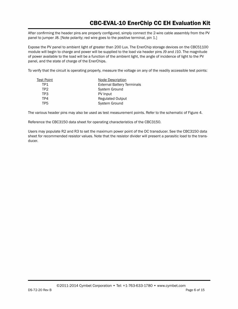
After confirming the header pins are properly configured, simply connect the 2-wire cable assembly from the PV panel to jumper J8. [Note polarity; red wire goes to the positive terminal, pin 1.]
Expose the PV panel to ambient light of greater than 200 Lux. The EnerChip storage devices on the CBC51100 module will begin to charge and power will be supplied to the load via header pins J9 and J10. The magnitude of power available to the load will be a function of the ambient light, the angle of incidence of light to the PV panel, and the state of charge of the EnerChips.
To verify that the circuit is operating properly, measure the voltage on any of the readily accessible test points:
Test Point Node Description TP1 External Battery Terminals TP2 System Ground TP3 PV Input TP4 Regulated Output TP5 System Ground
The various header pins may also be used as test measurement points. Refer to the schematic of Figure 4.
Reference the CBC3150 data sheet for operating characteristics of the CBC3150.
Users may populate R2 and R3 to set the maximum power point of the DC transducer. See the CBC3150 data sheet for recommended resistor values. Note that the resistor divider will present a parasitic load to the trans-ducer.
CBC-EVAL-10 EnerChip CC EH Evaluation Kit
©2011-2014 Cymbet Corporation • Tel: +1-763-633-1780 • www.cymbet.comDS-72-20 Rev B Page 7 of 15
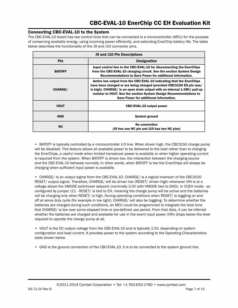
Connecting CBC-EVAL-10 to the SystemThe CBC-EVAL-10 board has two control lines that can be connected to a microcontroller (MCU) for the purpose of conserving available energy, using incoming power efficiently, and extending EnerChip battery life. The table below describes the functionality of the J9 and J10 connector pins.
• BATOFF is typically controlled by a microcontroller I/O line. When driven high, the CBC3150 charge pump will be disabled. This feature allows all available power to be delivered to the load rather than to charging the EnerChips, a useful mode when limited transducer power is available or when higher operating current is required from the system. When BATOFF is driven low, the interaction between the charging source and the CBC-EVAL-10 behaves normally. In other words, when BATOFF is low the EnerChips will always be charging when sufficient input power is available.
• CHARGE/ is an output signal from the CBC-EVAL-10. CHARGE/ is a logical inversion of the CBC3150 RESET/ output signal. Therefore, CHARGE/ will be driven low (RESET/ driven high) whenever VIN is at a voltage above the VMODE switchover setpoint (nominally 3.0V with VMODE tied to GND). In CCEH mode - as configured by jumper J11 - RESET/ is tied to EN, meaning the charge pump will be active and the batteries will be charging only when RESET/ is high. During operating conditions when RESET/ is toggling on and off at some duty cycle (for example in low light), CHARGE/ will also be toggling. To determine whether the batteries are charged during such conditions, an MCU could be programmed to integrate the total time that CHARGE/ is low over some elapsed time or pre-defined use period. From that data, it can be inferred whether the batteries are charged and available for use in the event input power (VIN) drops below the level required to operate the charge pump at all.
• VOUT is the DC output voltage from the CBC-EVAL-10 and is typically 2.5V, depending on system configuration and load current. It provides power to the system according to the Operating Characteristics table shown below.
• GND is the ground connection of the CBC-EVAL-10. It is to be connected to the system ground line.
J9 and J10 Pin Descriptions
Pin Designation
BATOFFInput control line to the CBC-EVAL-10 for disconnecting the EnerChips from the CBC-EVAL-10 charging circuit. See the section System Design
Recommendations to Save Power for additional information.
CHARGE/
Active low output from the CBC-EVAL-10 indicating that the EnerChips have been charged or are being charged (provided CBC3150 EN pin was/is high). CHARGE/ is an open drain output with an internal 1.0MΩ pull-up
resistor to VOUT. See the section System Design Recommendations to Save Power for additional information.
VOUT CBC-EVAL-10 output power
GND System ground
NC No connection(J9 has one NC pin and J10 has two NC pins)
CBC-EVAL-10 EnerChip CC EH Evaluation Kit
©2011-2014 Cymbet Corporation • Tel: +1-763-633-1780 • www.cymbet.comDS-72-20 Rev B Page 8 of 15
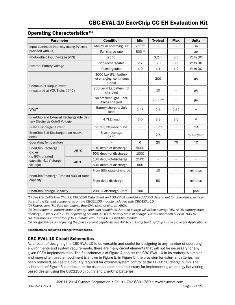
Operating Characteristics (1)
Specifications subject to change without notice.
(1) See DS-72-03 EnerChip CC CBC3150 Data Sheet and DS-72-01 EnerChip CBC050 Data Sheet for complete specifica-tions of the Cymbet components on the CBC51100 module included with CBC-EVAL-10.(2) Fluorescent (FL) light conditions. EnerChip state-of-charge >90%.(3) Dependent on battery state-of-charge and load conditions. State-of-charge will affect average VIN. At 0% battery state-of-charge, 2.6V < VIN < 3.1V, depending on load. At 100% battery state-of-charge, VIN will approach 5.2V at 700Lux.(4) Continuous current for up to 1 minute with CBC51100 EnerChip module.(5) For guidelines on adjusting the pulse current capability, see AN-1025: Using the EnerChip in Pulse Current Applications.
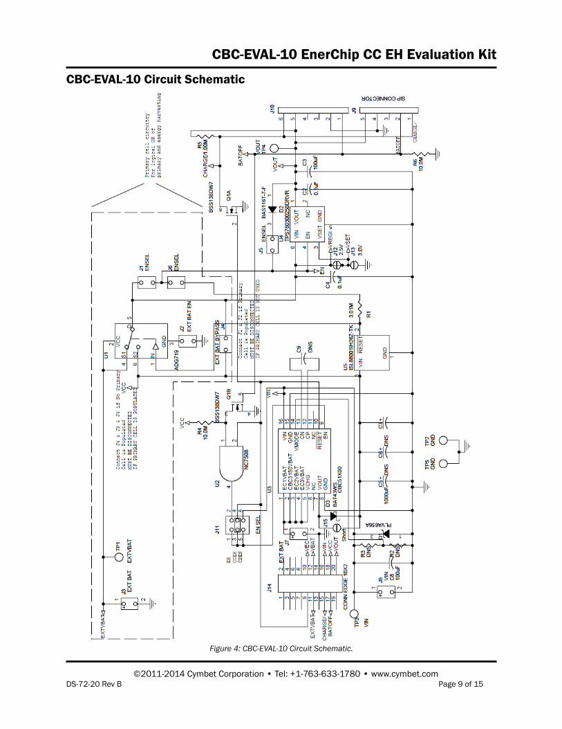
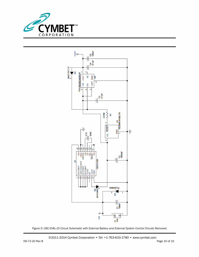
CBC-EVAL-10 Circuit SchematicsAs a result of designing the CBC-EVAL-10 to be versatile and useful for designing to any number of operating environments and system requirements, there are many circuit elements that will not be necessary for any given CCEH implementation. The full schematic of Figure 4 depicts the CBC-EVAL-10 in its entirety. A simpler and more often used embodiment is shown in Figure 5. In Figure 5, the provision for external batteries has been removed, as has the circuitry required for external system control of the CBC3150 charge pump. The schematic of Figure 5 is reduced to the essential elements necessary for implementing an energy harvesting-based design using the CBC3150 circuitry and EnerChip batteries.
Parameter Condition Min Typical Max Units
Input Luminous Intensity (using PV cells provided with kit)
Minimum operating Lux 250 (2) - - LuxFull charge rate 800 (2) - - Lux
Photovoltaic Input Voltage (VIN) 25°C 3.2 (3) 5.5 Volts DC
External Battery VoltageNon-rechargeable 2.7 3.0 3.6 Volts DC
Rechargeable 4.0 4.1 4.2 Volts DC
Continuous Output Power(measured at VOUT pin; 25°C)
1000 Lux (FL); battery not charging; continuous
output- 300 - µA
200 Lux (FL), battery not charging - 10 - µA
No ambient light, Ener-Chips charged - 2000 (4) - µA
VOUT Battery charged; 2µA load 2.48 2.5 2.52 V
EnerChip and External Rechargeable Bat-tery Discharge Cutoff Voltage 4.7kΩ load 3.0 3.3 3.6 V
Pulse Discharge Current 25°C ; 20 msec pulse - 30 (5) - mA
EnerChip Self-Discharge (non-recover-able)
5-year average25°C - 2.5 - % per year
Operating Temperature - 0 25 70 °C
EnerChip Recharge Cycles(to 80% of rated capacity; 4.1 V charge voltage)
25°C10% depth-of-discharge 5000 - - -
50% depth-of discharge 1000 - - -
40°C10% depth-of-discharge 2500 - - -
50% depth-of-discharge 500 - - -
EnerChip Recharge Time (to 80% of rated capacity)
From 50% state-of-charge - 10 - minutes
From deep discharge - 50 - minutes
EnerChip Storage Capacity 200 µA discharge; 25°C 100 - - µAh
CBC-EVAL-10 EnerChip CC EH Evaluation Kit
©2011-2014 Cymbet Corporation • Tel: +1-763-633-1780 • www.cymbet.comDS-72-20 Rev B Page 9 of 15
Figure 4: CBC-EVAL-10 Circuit Schematic.
CBC-EVAL-10 Circuit Schematic
©2011-2014 Cymbet Corporation • Tel: +1-763-633-1780 • www.cymbet.comDS-72-20 Rev B Page 10 of 15
Figure 5: CBC-EVAL-10 Circuit Schematic with External Battery and External System Control Circuits Removed.
CBC-EVAL-10 EnerChip CC EH Evaluation Kit
©2011-2014 Cymbet Corporation • Tel: +1-763-633-1780 • www.cymbet.comDS-72-20 Rev B Page 11 of 15
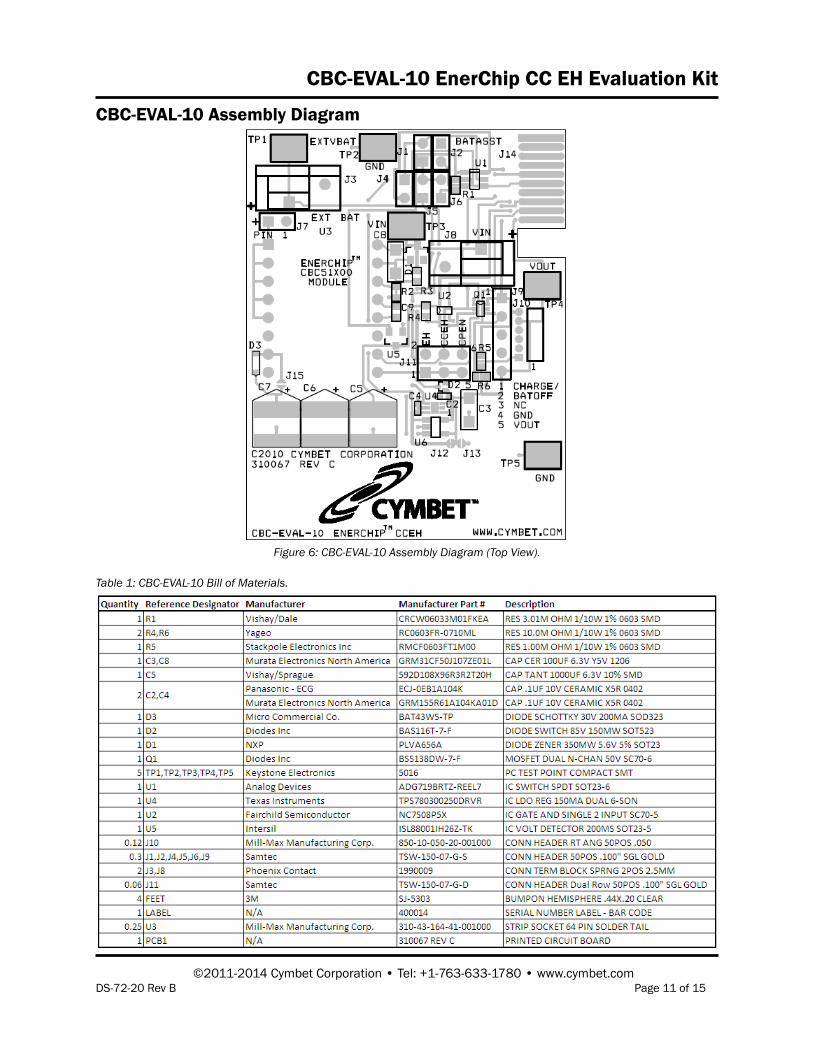
Figure 6: CBC-EVAL-10 Assembly Diagram (Top View).
CBC-EVAL-10 Assembly Diagram
Table 1: CBC-EVAL-10 Bill of Materials.
CBC-EVAL-10 EnerChip CC EH Evaluation Kit
©2011-2014 Cymbet Corporation • Tel: +1-763-633-1780 • www.cymbet.comDS-72-20 Rev B Page 12 of 15
Using Other Energy Harvesting TransducersCBC-EVAL-10 includes a standard amorphous silicon solar panel (Sanyo AM1815 type) configured as 8 series-connected cells on a glass substrate. The output voltage and current vary with incident light intensity, wave-length, and load impedance.
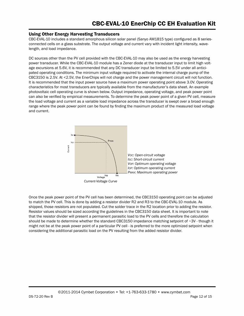
DC sources other than the PV cell provided with the CBC-EVAL-10 may also be used as the energy harvesting power transducer. While the CBC-EVAL-10 module has a Zener diode at the transducer input to limit high volt-age excursions at 5.6V, it is recommended that any DC transducer input be limited to 5.5V under all antici-pated operating conditions. The minimum input voltage required to activate the internal charge pump of the CBC3150 is 2.5V. At <2.5V, the EnerChips will not charge and the power management circuit will not function. It is recommended that the input power source have a maximum power operating point above 3.0V. Operating characteristics for most transducers are typically available from the manufacturer’s data sheet. An example photovoltaic cell operating curve is shown below. Output impedance, operating voltage, and peak power point can also be verified by empirical measurements. To determine the peak power point of a given PV cell, measure the load voltage and current as a variable load impedance across the transducer is swept over a broad enough range where the peak power point can be found by finding the maximum product of the measured load voltage and current.
Once the peak power point of the PV cell has been determined, the CBC3150 operating point can be adjusted to match the PV cell. This is done by adding a resistor divider R2 and R3 to the CBC-EVAL-10 module. As shipped, those resistors are not populated. Cut the solder trace in the R2 location prior to adding the resistor. Resistor values should be sized according the guidelines in the CBC3150 data sheet. It is important to note that the resistor divider will present a permanent parasitic load to the PV cells and therefore the calculation should be made to determine whether the standard CBC3150 impedance matching setpoint of ~3V - though it might not be at the peak power point of a particular PV cell - is preferred to the more optimized setpoint when considering the additional parasitic load on the PV resulting from the added resistor divider.
VOC: Open-circuit voltageISC: Short-circuit currentVOP: Optimum operating voltageIOP: Optimum operating currentPMAX: Maximum operating power
Current-Voltage Curve
CBC-EVAL-10 EnerChip CC EH Evaluation Kit
©2011-2014 Cymbet Corporation • Tel: +1-763-633-1780 • www.cymbet.comDS-72-20 Rev B Page 13 of 15
System Design Recommendations to Save PowerIn most system power budgets, the peak power required is not as critical as the length of time the power is required.
1. Careful selection of the message protocol for the RF link can have a significant impact on the overall power budget.
2. In many cases, using higher power analog circuits that can be turned on, settle quickly, and immediately turned off can decrease the overall energy consumed.
3. Microcontroller clock frequency can also have a significant impact on the power budget.4. In some applications it might be advantageous to use a higher microcontroller clock frequency to reduce
the time the microcontroller and peripheral circuits are active.5. Avoid using circuits that bias microcontroller digital inputs to mid-level voltages; this can cause significant
amounts of parasitic currents to flow.6. Use 22MΩ (or larger) pull-up/down resistors where possible. However, be aware that high circuit
impedances coupled with parasitic capacitance can make for a slow rise/fall time that can place the voltage on the microcontroller inputs at mid-levels, resulting in parasitic current flow. One solution to the problem is to enable the internal pull-up/down resistor of the microcontroller input to force the input to a known state, then disable the resistor when it’s time to check the state of the line. If using the microcontroller’s internal pull-up/down resistors on the inputs to bias push-button switches in a polled system, leave the pull-up/down resistor disabled and enable the resistor only while checking the state of the input port. Alternatively, in an interrupt-driven system, disable the pull-up/down resistor within the first few instructions in the interrupt service routine. Enable the pull-up/down resistor only after checking that the switch has been opened.
7. Microcontroller pull-up/down resistors are typically less than 100kΩ and will be a huge load on the system if left on continuously while a button is being pressed or if held for any significant length of time. For even greater reduction in power, use external pull-up/down resistors in the 10MΩ to 22MΩ range. Bias the external resistor not with the power rail but with a microcontroller port. The same algorithm used for internal pull-up/down resistors can then be used to save power.
8. The CHARGE/ line on the CBC-EVAL-10 has a 1.0MΩ pull-up resistor with a very slow rise time. Use an internal microcontroller pull-down resistor to force the CHARGE/ line low all of the time and then disable the pull-down resistor to check the state of the line. This will keep the CHARGE/ line from biasing the input at mid level for long periods of time, which could case large parasitic currents to flow.
9. The CBC-EVAL-10 module has a feature for disabling the CBC3150 charge pump. A handshake line BATOFF is provided for use of this feature. A high level will disable the charge pump. This is useful in very low ambient energy conditions to steer all of the available energy into the load. EnerChip batteries have very low self-discharge rates (typically 2.5% per year) so it is not necessary to continuously charge them.
10. While it is relatively straightforward to calculate a power budget and design a system to work within the constraints of the power and energy available, it is easy to overlook the power required to initialize the system to a known state and to complete the radio link with the host system or peer nodes in a mesh network. The initialization phase can sometimes take two to three times the power needed for steady state operation. Ideally, the hardware should be in a low power state when the system power-on reset is in its active state. If this is not possible, the microcontroller should place the hardware in a low power state as soon as possible. After this is done, the microcontroller should be put into a sleep state long enough for the energy harvester to replenish the energy storage device. If the power budget is not exceeded during this phase, the system can continue with its initialization. Next, the main initialization of the system, radio links, analog circuits, and so forth, can begin. Care should be taken to ensure that the time the system is on during this phase does not exceed the power budget. Several sleep cycles might be needed to ‘stairstep’ the system up to its main operational state. The Cymbet CBC-EVAL-10 module has a handshake line CHARGE/ to indicate to the microcontroller when energy is available. Another way to know whether energy is available is to have the microcontroller monitor the voltage on its power bus using one its internal A/D converters.

CBC-EVAL-10 EnerChip CC EH Evaluation Kit
©2011-2014 Cymbet Corporation • Tel: +1-763-633-1780 • www.cymbet.comDS-72-20 Rev B Page 14 of 15
Frequently Asked Questions
Q: I am not sure if I have enough input power to charge the EnerChip batteries?A: Measure the voltage on pin 1 of header connector J7. If the voltage is 4.1V, the EnerChips (and external rechargeable battery connected to J7, if any) are being charged. If the voltage is not 4.1V (+/- 50mV), there is insufficient power to charge the batteries.
Q: What if I short-circuit the output?A: The disconnect circuit will disconnect the EnerChip devices from the output after the capacitor is discharged below about 3.0V. This prevents the EnerChips from being discharged too deeply. The EnerChip cell will automatically reconnect after the capacitor is recharged.
Q: What happens if I want to run a larger pulse current application?A: See application note AN-1025. The output capacitor can be sized to drive almost any load as long as the duration is not too long. AN-1025 describes how to calculate the capacitor size.
Q: What happens if the EnerChip is short-circuited? Will it explode or leak harmful chemicals?A: No. There are no harmful chemicals to leak and the energy storage cells will not explode.
Q: How long will the CBC-EVAL-10 module operate with no ambient light?A: This depends on many factors, including load power consumption, EnerChip state-of-charge, operating temperature, etc. The EnerChips on the CBC51100 module provide 100µAh of discharge capacity when fully charged.
Q: How long will the CBC-EVAL-10 module last if I use it every day and input power is available most of the time?A: The CBC-EVAL-10 module should last at least 10 years.
Q: How long will the two EnerChips on the CBC51100 module hold a charge, assuming no input power?A: The self-discharge of the EnerChip is a function of several parameters, including temperature. Self- discharge specifications can be found in the product data sheets at http://www.cymbet.com/content/ products-resource-docs.asp.
Q: What happens if the EnerChip is left in a discharged state for a long period of time?A: Leaving the EnerChip in a discharged state is not detrimental to its performance.
Q: I see no voltage on VOUT.A: Make sure there is sufficient input power to operate the CBC3150 charge pump and that the output is not short-circuited.
Q: Will the CBC-EVAL-10 disconnect the EnerChips before they become too deeply depleted?A: Yes, the CBC-EVAL-10 has a cutoff circuit that will prevent the EnerChips from being damaged due to over-discharge. However, repeatedly operating the system in a mode that allows the cutoff circuit to be invoked at deep discharge will cause premature capacity fade and shorter product life. If it is anticipated that the low voltage cutoff point will be reached, it is better to put the system into a high power mode to force cutoff at a higher state-of-charge, thereby prolonging the life of the EnerChips.

CBC-EVAL-10 EnerChip CC EH Evaluation Kit
©2011-2014 Cymbet Corporation • Tel: +1-763-633-1780 • www.cymbet.comDS-72-20 Rev B Page 15 of 15
Cymbet, the Cymbet Logo and EnerChip are trademarks of Cymbet Corporation. All Rights Reserved.EnerChip products and technology are covered by one or more patents or patents pending.
Disclaimer of Warranties; As IsThe information provided in this data sheet is provided “As Is” and Cymbet Corporation disclaims all representations or warranties of any kind, express or implied, relating to this data sheet and the Cymbet battery product described herein, including without limitation, the implied warranties of merchantability, fitness for a particular purpose, non-infringement, title, or any warranties arising out of course of dealing, course of performance, or usage of trade. Cymbet battery products are not approved for use in life critical applications. Users shall confirm suitability of the Cymbet battery product in any products or applications in which the Cymbet battery product is adopted for use and are solely responsible for all legal, regulatory, and safety-related requirements concerning their products and applications and any use of the Cymbet battery product described herein in any such product or applications.
EnerChip Part Number Description NotesCBC-EVAL-10 EnerChip CC Energy Harvester
Evaluation KitContains Solar Cell Panel and
CBC51100 ModuleCBC3150-D9C EnerChip CC with Integrated Power
ManagementPackaged in Tape and Reel or
TubesCBC050-M8C EnerChip 50µAh Solid State
BatteryPackaged in Tape and Reel or
Tubes
Ordering Information - Products Discontinued and Not Available
Power Conversion Efficiency ConsiderationsSystem factors such as PV cell properties; ambient light; input and output capacitor sizes; battery state-of-charge; and CBC3150 VMODE peak power setting will all affect the duty cycle of the CBC3150 charge pump and system power conversion efficiency.
The CBC3150 has a built-in latency of about 200ms with respect to the timing of RESET/ being asserted low af-ter the charge pump is disabled. For optimum power conversion efficiency, size the input capacitor so that it will only charge one or two tenths of a volt during that 200ms period under the lowest anticipated lighting condition - that is, where the PV cell gives its lowest power output.
For example, suppose the PV cell at 200Lux can deliver 50µA at a maximum power point of 3.0V. Transposing the standard equation I = C x dv/dt, the input capacitor can be sized as C = 50µA x 200ms/100mV = 100µF of capacitance. When the charge pump runs, it will quickly pump the capacitor to the switching point. When the charge pump stops during the 200ms latency time, the capacitor will not charge above the maximum power point. At higher light intensity, the efficiency is less important and thus the capacitor does not need to be over-sized to maintain operation at the peak power point of the PV cell.


![Srm 10 Eval Guide[1]](https://img.pdfslide.net/doc/110x75/577d36561a28ab3a6b92cccb/srm-10-eval-guide1.jpg)