Embed Size (px)
Citation preview
Product Technical Specification nbn™ BSS ILA Product Module
nbn™ BSS Interim Launch Agreement
This document forms part of the nbn™ BSS Interim Launch Agreement, which is a Standard Form of Access Agreement for the purposes of Part XIC of the Competition and Consumer Act 2010.
SFAA - nbn™ BSS Interim Launch Agreement - Product Technical Specification - nbn™ BSS ILA Product Module 2
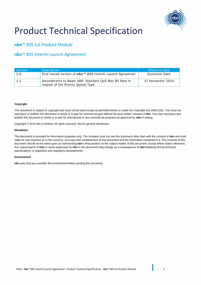
Product Technical Specification nbn™ BSS ILA Product Module
nbn™ BSS Interim Launch Agreement
Version Description Effective Date 1.0 First issued version of nbn™ BSS Interim Launch Agreement Execution Date
1.1 Amendments to Beam ABP, Standard QoS Max Bit Rate in respect of the Priority Queue Type
27 November 2019
Copyright
This document is subject to copyright and must not be used except as permitted below or under the Copyright Act 1968 (Cth). You must not reproduce or publish this document in whole or in part for commercial gain without the prior written consent of nbn. You may reproduce and publish this document in whole or in part for educational or non-commercial purposes as approved by nbn in writing.
Copyright © 2019 nbn co limited. All rights reserved. Not for general distribution.
Disclaimer
This document is provided for information purposes only. The recipient must not use this document other than with the consent of nbn and must make its own inquiries as to the currency, accuracy and completeness of this document and the information contained in it. The contents of this document should not be relied upon as representing nbn’s final position on the subject matter of this document, except where stated otherwise. Any requirements of nbn or views expressed by nbn in this document may change as a consequence of nbn finalising formal technical specifications, or legislative and regulatory developments.
Environment
nbn asks that you consider the environment before printing this document.
SFAA - nbn™ BSS Interim Launch Agreement - Product Technical Specification - nbn™ BSS ILA Product Module 3
Roadmap A roadmap describing the structure of this nbn™ BSS ILA Product Technical Specification is provided below.
Product Technical Specification ........................................................................................................................... 2
1 Scope and purpose ....................................................................................................................................... 6
1.1 Purpose ..................................................................................................................................................... 6
1.2 Scope ......................................................................................................................................................... 6
1.3 Definitions ................................................................................................................................................. 6
2 Introduction ................................................................................................................................................. 7
2.1 The nbn™ BSS Products ............................................................................................................................ 7
2.1.1 nbn™ BSS Products ........................................................................................................................... 7
2.1.2 Product Components and Product Features .................................................................................... 7
2.1.2.1 B-NNI (BSS Network-Network Interface) ................................................................................... 8
2.1.2.2 UNI (User Network Interface) .................................................................................................... 8
2.1.2.3 BVC (Broadband Virtual Connection) ......................................................................................... 8
2.1.2.4 IAC (Internet Access Connection) .............................................................................................. 8
2.1.3 Product Features .............................................................................................................................. 9
2.2 Access Components ................................................................................................................................ 10
3 BSS Network-Network Interface (B-NNI) ..................................................................................................... 11
3.1 B-NNI Bearers .......................................................................................................................................... 11
3.2 B-NNI Redundancy mode ........................................................................................................................ 11
3.2.1 Single Interface (Single BSS POI) ..................................................................................................... 12
3.2.2 Redundant Interface (Single BSS POI) ............................................................................................. 12
3.2.3 Single Interface (Redundant BSS POI) ............................................................................................. 12
3.2.4 Redundant Interface (Redundant BSS POI) .................................................................................... 12
3.3 BVC Support ............................................................................................................................................ 13
3.4 Layer 3 Protocol Support ........................................................................................................................ 13
3.4.1 nbn™ ABSL3 .................................................................................................................................... 13
3.5 Orderable B-NNI Attributes..................................................................................................................... 13
3.5.1 B-NNI ............................................................................................................................................... 13
3.5.1.1 B-NNI Redundancy Mode ......................................................................................................... 13
3.5.1.2 B-NNI Orderable Attributes Summary ..................................................................................... 14
3.5.2 B-NNI Bearer ................................................................................................................................... 14
SFAA - nbn™ BSS Interim Launch Agreement - Product Technical Specification - nbn™ BSS ILA Product Module 4
3.5.2.1 B-NNI Bearer Ordering ............................................................................................................. 14
3.5.2.2 B-NNI Bearer Orderable Attributes .......................................................................................... 14
4 User Network Interface (UNI-D) .................................................................................................................. 16
4.1 Overview ................................................................................................................................................. 16
4.2 Addressing Mode .................................................................................................................................... 16
4.2.1 VSAT NTD IP Addressing Modes ..................................................................................................... 16
4.3 Physical Interface .................................................................................................................................... 17
4.4 Scalability Factors .................................................................................................................................... 18
4.4.1 Line Rate ......................................................................................................................................... 18
4.4.2 Information Rate ............................................................................................................................. 18
4.5 IAC and BVC Support ............................................................................................................................... 18
4.6 Resilience ................................................................................................................................................ 19
4.7 VSAT NTD Supply ..................................................................................................................................... 19
4.8 Orderable UNI-D Attributes .................................................................................................................... 19
4.8.1 Configuration Attributes ................................................................................................................. 19
5 Broadband Virtual Connection (BVC) .......................................................................................................... 21
5.1 Overview ................................................................................................................................................. 21
5.2 Information Rate Bandwidth Profile ....................................................................................................... 22
5.3 VLANs ...................................................................................................................................................... 22
5.4 UNI to UNI ............................................................................................................................................... 22
5.5 Orderable BVC Attributes ....................................................................................................................... 23
5.5.1 BVC Configuration Attributes ......................................................................................................... 23
5.5.2 BVC Service Attributes .................................................................................................................... 23
6 Internet Access Connection (IAC) ................................................................................................................ 25
6.1 Overview ................................................................................................................................................. 25
6.2 Information Rate Bandwidth Profile ....................................................................................................... 25
6.3 Data Usage Allowance ............................................................................................................................. 25
6.4 Orderable IAC Attributes ......................................................................................................................... 26
6.4.1 IAC Configuration Attributes .......................................................................................................... 26
6.4.2 IAC Service Attributes ..................................................................................................................... 26
7 Other Service Attributes ............................................................................................................................. 28
7.1.1.1 VSAT NTD Attributes ................................................................................................................ 28
SFAA - nbn™ BSS Interim Launch Agreement - Product Technical Specification - nbn™ BSS ILA Product Module 5
8 Product Features ........................................................................................................................................ 29
8.1 Access Bandwidth Pool (ABP) ................................................................................................................. 29
8.1.1 Beam ABP ........................................................................................................................................ 29
8.2 Burst ........................................................................................................................................................ 31
8.3 Additional VLANs ..................................................................................................................................... 31
8.4 Bandwidth on Demand (BoD) ................................................................................................................. 31
8.5 Disaster Recovery (DR) ............................................................................................................................ 32
8.6 Encryption ............................................................................................................................................... 32
8.7 Fleet Plan ................................................................................................................................................. 33
8.8 Performance Enhancing Proxy (PEP) ....................................................................................................... 33
8.8.1 HTTP Acceleration ........................................................................................................................... 33
8.8.2 TCP Acceleration ............................................................................................................................. 35
8.9 Quality of Service (QoS) Marking ............................................................................................................ 37
8.10 Time of Day (ToD) ................................................................................................................................... 39
8.11 VoIP Prioritisation ................................................................................................................................... 40
9 Service Performance ................................................................................................................................... 42
9.1 QoS Class Performance ........................................................................................................................... 42
10 BSS Class of Service (CoS) ...................................................................................................................... 43
10.1 BSS CoS Architecture ............................................................................................................................... 43
10.1.1 Bandwidth Profiles Parameter Considerations............................................................................... 43
10.1.1.1 Calculation of Information Rate ............................................................................................. 43
10.1.1.2 Committed Information Rate ................................................................................................. 43
10.1.1.3 Peak Information Rate ........................................................................................................... 43
10.1.1.4 Network Burst ........................................................................................................................ 43
SFAA - nbn™ BSS Interim Launch Agreement - Product Technical Specification - nbn™ BSS ILA Product Module 6
1 Scope and purpose
1.1 Purpose This nbn™ BSS ILA Product Technical Specification sets out the technical specifications for the nbn™ BSS Products. It forms part of the nbn™ BSS Interim Launch Agreement.
1.2 Scope Sections 2 to 10 of this nbn™ BSS ILA Product Technical Specification describe the features of the nbn™ BSS Products, as offered by nbn in the nbn™ BSS Interim Launch Agreement. Any differences in availability or performance of these features between the nbn™ BSS Products are detailed in this nbn™ BSS ILA Product Technical Specification and the nbn™ BSS ILA Network Interface Specification, where necessary.
1.3 Definitions Capitalised terms used but not defined in this nbn™ BSS ILA Product Technical Specification have the meaning given in the nbn™ BSS ILA Dictionary.
If a capitalised term used in this document is not defined in the nbn™ BSS ILA Dictionary, then that term has the ordinary meaning commonly accepted in the industry.
SFAA - nbn™ BSS Interim Launch Agreement - Product Technical Specification - nbn™ BSS ILA Product Module 7
2 Introduction
2.1 The nbn™ BSS Products This section provides a brief overview of the nbn™ BSS Products that Customers may choose to acquire:
2.1.1 nbn™ BSS Products
(a) Each of the following is an nbn™ BSS Product:
(i) nbn™ Virtual Internet Service Product (nbn™ VISP);
(ii) nbn™ Internet of Things (nbn™ IoT); and
(iii) nbn™ Access Bandwidth Services Layer 3 (nbn™ ABSL3).
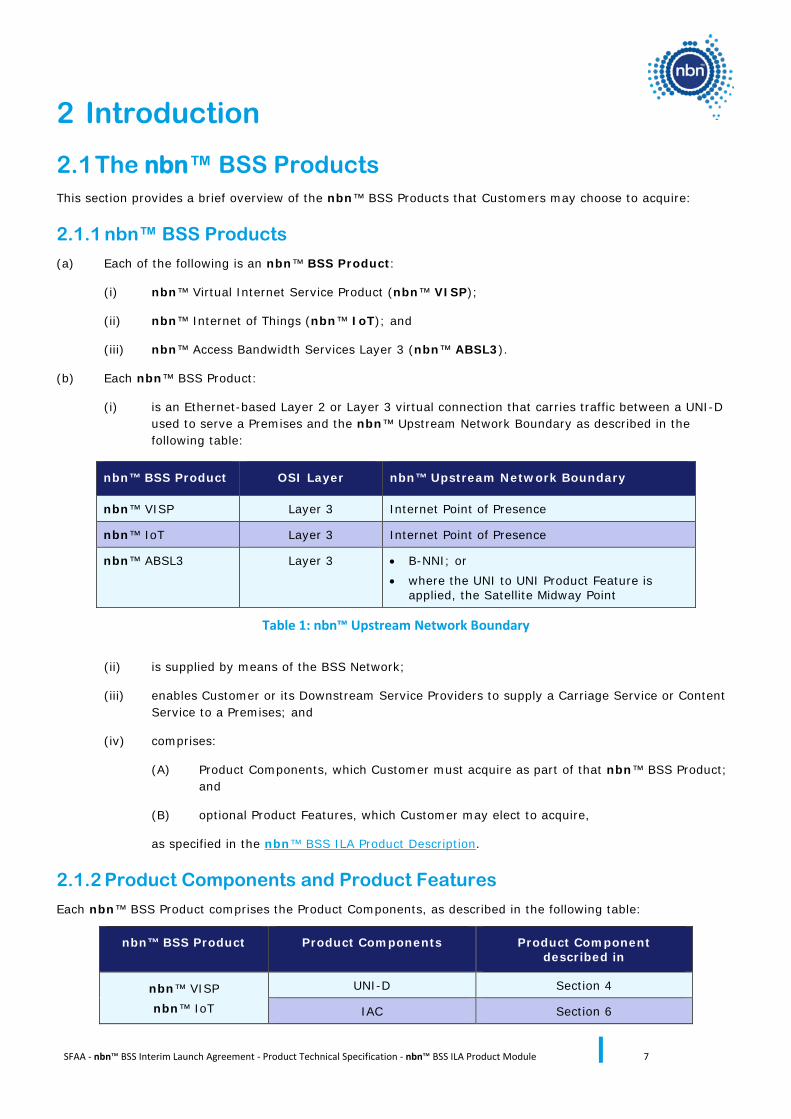
(b) Each nbn™ BSS Product:
(i) is an Ethernet-based Layer 2 or Layer 3 virtual connection that carries traffic between a UNI-D used to serve a Premises and the nbn™ Upstream Network Boundary as described in the following table:
nbn™ BSS Product OSI Layer nbn™ Upstream Network Boundary
nbn™ VISP Layer 3 Internet Point of Presence
nbn™ IoT Layer 3 Internet Point of Presence
nbn™ ABSL3 Layer 3 • B-NNI; or • where the UNI to UNI Product Feature is
applied, the Satellite Midway Point
Table 1: nbn™ Upstream Network Boundary
(ii) is supplied by means of the BSS Network;
(iii) enables Customer or its Downstream Service Providers to supply a Carriage Service or Content Service to a Premises; and
(iv) comprises:
(A) Product Components, which Customer must acquire as part of that nbn™ BSS Product; and
(B) optional Product Features, which Customer may elect to acquire,
as specified in the nbn™ BSS ILA Product Description.
2.1.2 Product Components and Product Features
Each nbn™ BSS Product comprises the Product Components, as described in the following table:
nbn™ BSS Product Product Components Product Component described in
nbn™ VISP nbn™ IoT
UNI-D Section 4
IAC Section 6
SFAA - nbn™ BSS Interim Launch Agreement - Product Technical Specification - nbn™ BSS ILA Product Module 8
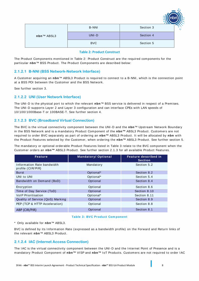
nbn™ ABSL3
B-NNI Section 3
UNI-D Section 4
BVC Section 5
Table 2: Product Construct
The Product Components mentioned in Table 2: Product Construct are the required components for the particular nbn™ BSS Product. The Product Components are described below:
2.1.2.1 B-NNI (BSS Network-Network Interface)
A Customer acquiring an nbn™ ABSL3 Product is required to connect to a B-NNI, which is the connection point at a BSS POI between the Customer and the BSS Network.
See further section 3.
2.1.2.2 UNI (User Network Interface)
The UNI-D is the physical port to which the relevant nbn™ BSS service is delivered in respect of a Premises. The UNI-D supports Layer 2 and Layer 3 configuration and can interface CPEs with LAN speeds of 10/100/1000Base-T or 100BASE-T. See further section 4.
2.1.2.3 BVC (Broadband Virtual Connection)
The BVC is the virtual connectivity component between the UNI-D and the nbn™ Upstream Network Boundary in the BSS Network and is a mandatory Product Component of the nbn™ ABSL3 Product. Customers are not required to order BVC separately as part of ordering an nbn™ ABSL3 Product. It will be allocated by nbn with the Product Features selected by the Customer, when ordering the nbn™ ABSL3 Product. See further section 5.
The mandatory or optional orderable Product Features listed in Table 3 relate to the BVC component when the Customer orders an nbn™ ABSL3 Product. See further section 2.1.3 for all available Product Features.
Feature Mandatory/Optional Feature described in Section
Information Rate bandwidth profile (CIR/PIR)
Mandatory Section 5.2
Burst Optional* Section 8.2 UNI to UNI Optional* Section 5.4 Bandwidth on Demand (BoD) Optional Section 8.4
Encryption Optional Section 8.6 Time of Day Service (ToD) Optional Section 8.10 VoIP Prioritisation Optional* Section 8.11 Quality of Service (QoS) Marking Optional Section 8.9 PEP (TCP & HTTP Acceleration) Optional Section 8.8
ABP (CIR/PIR) Optional Section 8.1
Table 3: BVC Product Component
* Only available for nbn™ ABSL3.
BVC is defined by its Information Rate (expressed as a bandwidth profile) on the Forward and Return links of the relevant nbn™ ABSL3 Product.
2.1.2.4 IAC (Internet Access Connection)
The IAC is the virtual connectivity component between the UNI-D and the Internet Point of Presence and is a mandatory Product Component of nbn™ VISP and nbn™ IoT Products. Customers are not required to order IAC
SFAA - nbn™ BSS Interim Launch Agreement - Product Technical Specification - nbn™ BSS ILA Product Module 9
separately as part of ordering an nbn™ VISP or nbn™ IoT Product. It will be allocated with the Product Features selected by the Customer, when ordering nbn™ VISP or nbn™ IoT. See further section 6.
For nbn™ VISP, IAC is defined by the Information Rate (expressed as a bandwidth profile) on the Forward and Return links and the data usage allowance. For nbn™ IoT, IAC is defined by the Information Rate (expressed as a bandwidth profile) on the Forward and Return links.
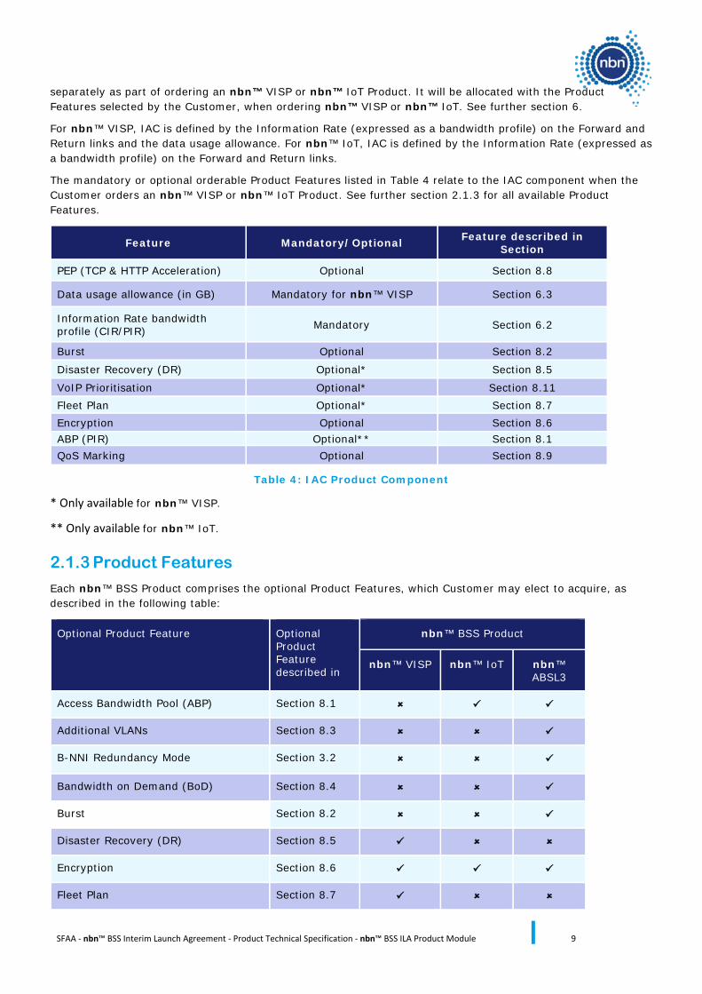
The mandatory or optional orderable Product Features listed in Table 4 relate to the IAC component when the Customer orders an nbn™ VISP or nbn™ IoT Product. See further section 2.1.3 for all available Product Features.
Feature Mandatory/Optional Feature described in Section
PEP (TCP & HTTP Acceleration) Optional Section 8.8
Data usage allowance (in GB) Mandatory for nbn™ VISP Section 6.3
Information Rate bandwidth profile (CIR/PIR) Mandatory Section 6.2
Burst Optional Section 8.2
Disaster Recovery (DR) Optional* Section 8.5
VoIP Prioritisation Optional* Section 8.11 Fleet Plan Optional* Section 8.7 Encryption Optional Section 8.6 ABP (PIR) Optional** Section 8.1 QoS Marking Optional Section 8.9
Table 4: IAC Product Component
* Only available for nbn™ VISP.
** Only available for nbn™ IoT.
2.1.3 Product Features
Each nbn™ BSS Product comprises the optional Product Features, which Customer may elect to acquire, as described in the following table:
Optional Product Feature Optional Product Feature described in
nbn™ BSS Product
nbn™ VISP nbn™ IoT nbn™ ABSL3
Access Bandwidth Pool (ABP) Section 8.1
Additional VLANs Section 8.3
B-NNI Redundancy Mode Section 3.2
Bandwidth on Demand (BoD) Section 8.4
Burst Section 8.2
Disaster Recovery (DR) Section 8.5
Encryption Section 8.6
Fleet Plan Section 8.7
SFAA - nbn™ BSS Interim Launch Agreement - Product Technical Specification - nbn™ BSS ILA Product Module 10
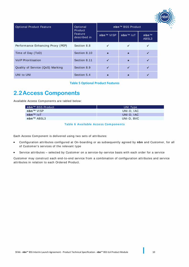
Optional Product Feature Optional Product Feature described in
nbn™ BSS Product
nbn™ VISP nbn™ IoT nbn™ ABSL3
Performance Enhancing Proxy (PEP) Section 8.8
Time of Day (ToD) Section 8.10
VoIP Prioritisation Section 8.11
Quality of Service (QoS) Marking Section 8.9
UNI to UNI Section 5.4
Table 5 Optional Product Features
2.2 Access Components Available Access Components are tabled below:
nbn™ BSS Product UNI Type nbn™ VISP UNI-D, IAC nbn™ IoT UNI-D, IAC nbn™ ABSL3 UNI-D, BVC
Table 6 Available Access Components
Each Access Component is delivered using two sets of attributes:
• Configuration attributes configured at On-boarding or as subsequently agreed by nbn and Customer, for all of Customer’s services of the relevant type
• Service attributes – selected by Customer on a service-by-service basis with each order for a service
Customer may construct each end-to-end service from a combination of configuration attributes and service attributes in relation to each Ordered Product.
SFAA - nbn™ BSS Interim Launch Agreement - Product Technical Specification - nbn™ BSS ILA Product Module 11
3 BSS Network-Network Interface (B-NNI) Section 3 of the nbn™ BSS ILA Product Description describes the B-NNI Product Component and the B-NNI Bearers. This section provides further product-level specification of the B-NNI Bearers, B-NNI Redundancy mode and BVC support characteristics of the B-NNI Product Component.
• B-NNIs associated with an nbn™ ABSL3 service will support BGP and static routes at the B-NNI to exchange route information with the Customer.
Detailed network-level specifications are set out in the nbn™ BSS ILA Network Interface Specification.
3.1 B-NNI Bearers Physical interface options for a B-NNI Bearer are:
• 1000BaseLX
• 1000BaseEX
• 10GBaseLR
• 10GBaseER
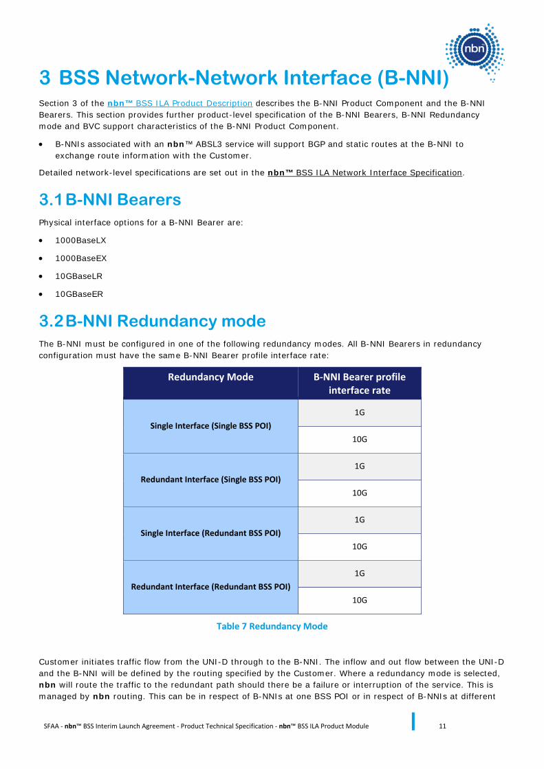
3.2 B-NNI Redundancy mode The B-NNI must be configured in one of the following redundancy modes. All B-NNI Bearers in redundancy configuration must have the same B-NNI Bearer profile interface rate:
Redundancy Mode B-NNI Bearer profile interface rate
Single Interface (Single BSS POI) 1G
10G
Redundant Interface (Single BSS POI) 1G
10G
Single Interface (Redundant BSS POI) 1G
10G
Redundant Interface (Redundant BSS POI) 1G
10G
Table 7 Redundancy Mode
Customer initiates traffic flow from the UNI-D through to the B-NNI. The inflow and out flow between the UNI-D and the B-NNI will be defined by the routing specified by the Customer. Where a redundancy mode is selected, nbn will route the traffic to the redundant path should there be a failure or interruption of the service. This is managed by nbn routing. This can be in respect of B-NNIs at one BSS POI or in respect of B-NNIs at different
SFAA - nbn™ BSS Interim Launch Agreement - Product Technical Specification - nbn™ BSS ILA Product Module 12
BSS POIs subject to the redundancy configuration selected by the Customer and the type of the failure or interruption.
3.2.1 Single Interface (Single BSS POI)
When a B-NNI is configured with no B-NNI redundancy, the B-NNI Bearer will be provisioned with a single B-NNI interface (1G or 10G) at the BSS POI selected by Customer. If the B-NNI fails, traffic may be dropped.
3.2.2 Redundant Interface (Single BSS POI)
When a B-NNI is configured as Redundant Interface (Single BSS POI), redundant B-NNI Bearers will each be provisioned at the BSS POI selected by Customer.
The B-NNI Bearers will operate in a 1:1 protection mode, meaning that if the primary B-NNI Bearer fails, traffic will be re-directed to the other B-NNI Bearer.
3.2.3 Single Interface (Redundant BSS POI)
When a B-NNI is configured as Single Interface (Redundant BSS POI), a single B-NNI Bearer will be provisioned at each BSS POI.
The B-NNI Bearers will operate in a 1:1 protection mode, meaning that if the primary B-NNI Bearer fails, traffic will be re-directed to the other B-NNI Bearer at the other BSS POI.
Note:
• It is the Customer’s responsibility to arrange backhaul from the Customer Network to each BSS POI and manage Customer’s network orchestration between the two B-NNI Bearers in the case of failover.
3.2.4 Redundant Interface (Redundant BSS POI)
When a B-NNI is configured as Redundant Interface (Redundant BSS POI), 2 B-NNI Bearers will be provisioned at each BSS POI.
For nbn™ ABSL3, the B-NNIs may operate in Active-Standby or Active-Active configuration. Customer can choose and control the active B-NNIs and determine failover conditions (e.g. where a B-NNI at one site is unavailable) and load balancing (i.e. sharing traffic between two or more B-NNIs) using BGP.
Notes:
1. It is the responsibility of the Customer to configure its routers to manage failover and load balancing with nbn™ ABSL3.
2. It is the Customer’s responsibility to arrange backhaul from Customer’s network to each BSS POI and manage Customer’s network orchestration between the four B-NNI Bearers to manage all failovers.
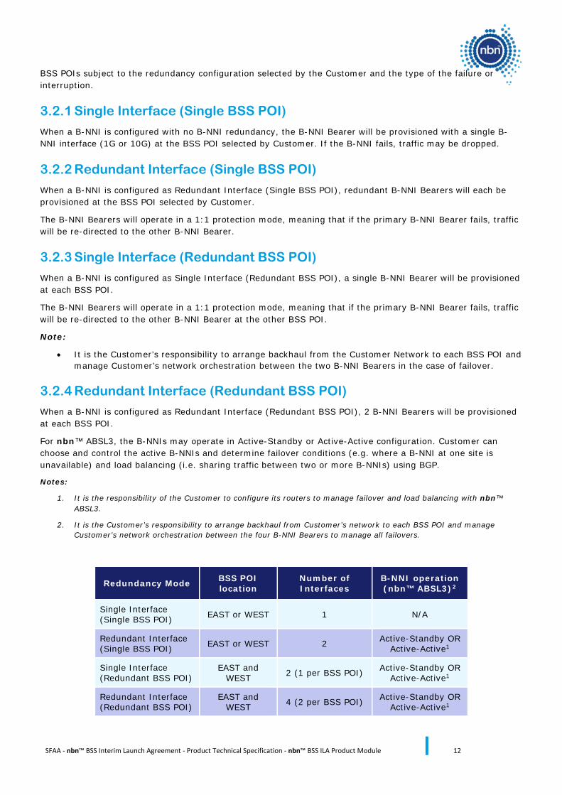
Redundancy Mode BSS POI location
Number of Interfaces
B-NNI operation (nbn™ ABSL3)2
Single Interface (Single BSS POI) EAST or WEST 1 N/A
Redundant Interface (Single BSS POI) EAST or WEST 2 Active-Standby OR
Active-Active1
Single Interface (Redundant BSS POI)
EAST and WEST 2 (1 per BSS POI) Active-Standby OR
Active-Active1
Redundant Interface (Redundant BSS POI)
EAST and WEST 4 (2 per BSS POI) Active-Standby OR
Active-Active1
SFAA - nbn™ BSS Interim Launch Agreement - Product Technical Specification - nbn™ BSS ILA Product Module 13
Table 8 B-NNI Redundancy modes
Note:
1. To be configured by Customer at their discretion using BGP attributes which will be defined and agreed between nbn and Customer during Solution Design Workshops.
2. For nbn™ ABSL3, where Customer acquires Single Interface (Redundant BSS POI) or Redundant Interface (Redundant BSS POI), it will be the Customer’s responsibility to use BGP local-preference and AS-Path features to automate and orchestrate the BGP failover between BSS POIs.
3.3 BVC Support The B-NNI will transparently support the BSS Traffic Class and priority encoding/decoding model set out in section 8.9, as detailed further in section 4.5 of the nbn™ BSS ILA Network Interface Specification.
3.4 Layer 3 Protocol Support
3.4.1 nbn™ ABSL3
BGP protocol (RFC 4271) is used to interface to the Customer Network across the B-NNI and receive routing updates from the network. A ‘static’ route is subject to agreement between Customer and nbn at a Solution Design Workshop. The Solution Design Workshop will be held for both nbn and the Customer to jointly understand customer experience required and configuration capabilities provided by the nbn™ BSS Product to provide an end-to-end solution to seek to meet Customer requirements.
3.5 Orderable B-NNI Attributes B-NNI has the following orderable attributes.
3.5.1 B-NNI
The B-NNI has the following attributes:
• Location
• Interface rate
• Redundancy mode
• Set of B-NNI Bearers
• Layer 2 or Layer 3 functional characteristics
3.5.1.1 B-NNI Redundancy Mode
The B-NNI can be configured in one of the following redundancy modes:
• Single Interface (Single BSS POI)
• Redundant Interface (Single BSS POI)
• Single Interface (Redundant BSS POI)
• Redundant Interface (Redundant BSS POI)
In order to change the redundancy mode of a B-NNI, Customer must order a new B-NNI in the intended redundancy mode and transition existing BVCs from the previous B-NNI. Once completed, the previous B-NNI may be cancelled.
SFAA - nbn™ BSS Interim Launch Agreement - Product Technical Specification - nbn™ BSS ILA Product Module 14
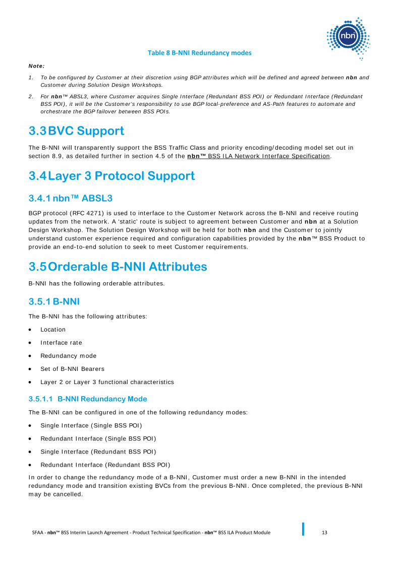
3.5.1.2 B-NNI Orderable Attributes Summary
Component Attributes Attribute Description
Selectable Options
Service details Physical Location Physical location of B-NNI BSS POI Site (EAST or WEST)
B-NNI Attributes Redundancy Mode Physical interface type
Single Interface (Single BSS POI) (default)
Redundant Interface (Single BSS POI)
Single Interface (Redundant BSS POI)
Redundant Interface (Redundant BSS POI)
Table 9 B-NNI Orderable Attributes
3.5.2 B-NNI Bearer
3.5.2.1 B-NNI Bearer Ordering
B-NNI Bearers are ordered through a B-NNI.
A feasibility check will be required upon addition of any B-NNI Bearer to a B-NNI, to determine whether the number of allowable B-NNI Bearers within the B-NNI has been exceeded.
nbn initially provisions each completed B-NNI Bearer order to Customer in an administratively “down” state. nbn will change this to an “up” state in co-ordination with Customer.
The following activities may be performed on a B-NNI, with respect to the set of B-NNI Bearers:
• establish a new B-NNI through ordering at least one B-NNI Bearer (Single Interface) or at least one pair of B-NNI Bearers (Redundant Interface)
• modify an existing B-NNI through adding/removing B-NNI Bearer(s)
• cancel an existing B-NNI– all underlying B-NNI Bearers will be automatically cancelled
For B-NNI configured as Single Interface (Single BSS POI or Redundant BSS POI), B-NNI Bearers may be ordered as single interfaces.
For B-NNI configured as Redundant Interface (Single BSS POI or Redundant BSS POI), B-NNI Bearers must be ordered in pairs.
Note: nbn intends to schedule an Outage with Customer to augment the B-NNI with additional B-NNI Bearers unless nbn notifies Customer that an Outage is not necessary.
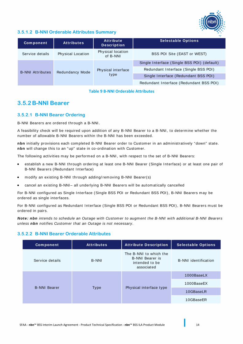
3.5.2.2 B-NNI Bearer Orderable Attributes
Component Attributes Attribute Description Selectable Options
Service details B-NNI
The B-NNI to which the B-NNI Bearer is intended to be
associated
B-NNI identification
B-NNI Bearer Type Physical interface type
1000BaseLX
1000BaseEX
10GBaseLR
10GBaseER

SFAA - nbn™ BSS Interim Launch Agreement - Product Technical Specification - nbn™ BSS ILA Product Module 15
Table 10 B-NNI Bearer Service Attributes
Customer must separately acquire the necessary facilities access rights to connect the B-NNI Bearer to Customer’s backhaul transmission cables or Customer Active Equipment.
SFAA - nbn™ BSS Interim Launch Agreement - Product Technical Specification - nbn™ BSS ILA Product Module 16
4 User Network Interface (UNI-D)
4.1 Overview The UNI-D is an Ethernet interface port on the VSAT NTD for the purposes of data carriage. It is the downstream physical demarcation point which separates the responsibility of the Customer from that of nbn. Each UNI-D will be assigned to a single service operating in total isolation from any other UNI-D and the Customer may deliver one service over that UNI-D.
UNI-D is compliant with IEEE 802.3 standards. Each UNI-D is regarded as a fully independent interface, operating in total isolation from any other UNI-D residing on the same VSAT NTD. The aggregate of all UNI-D throughput Information Rates on a VSAT NTD cannot exceed the relevant VSAT NTD throughput limit set out in the nbn™ BSS ILA Product Description and in the nbn™ BSS ILA Network Interface Specification.
In respect of nbn™ VISP and nbn™ IoT, each UNI-D is logically connected to the Internet Point of Presence via an IAC. In respect of nbn™ ABSL3 each UNI-D is logically connected via a BVC to a B-NNI, and to the Satellite Midway Point if UNI-to-UNI configuration applies.
The UNI-D will be associated with an active IAC for nbn™ VISP or nbn™ IoT Products or an active BVC for nbn™ ABSL3 Products (as the case may be) at all times.
Note: Only one UNI-D port can be active and provisioned per VSAT NTD. Any additional UNI-D ports on a VSAT NTD are for nbn’s management and troubleshooting use and will not be available for Customer traffic.
4.2 Addressing Mode The UNI-D supports a number of interface tagging, prioritisation addressing, and Quality of Service mapping modes as described in the nbn™ BSS ILA Network Interface Specification.
Note: Not all addressing modes are available in respect of all nbn™ BSS Products.
4.2.1 VSAT NTD IP Addressing Modes
Two VSAT NTD IP addressing modes are supported:
• NAT mode: This mode is supported by nbn™ VISP and nbn™ IoT. By default, a unique single static usable public IPv4 is allocated to each nbn™ VISP and nbn™ IoT service. This IP Address is allocated to the UNI-D and all the Customer Equipment connected to the UNI-D must use NAT. The IP range used for NAT is set at the time of ordering. This IP range may be allocated by Customer to Customer Equipment or End User Equipment statically or via the DHCP provided by the VSAT NTD. DHCP is enabled by default at the time of ordering and cannot be disabled. The full IP Address range (X.X.X.(0-254)) will be enabled. By default, the NAT IP address allocation range is /32 192.168.99.0 but can be changed via the nbn™ BSS Portal.
• Route mode: This mode is supported by nbn™ VISP, nbn™ IoT and nbn™ ABSL3. It is the default mode for nbn™ ABSL3 Products and cannot be altered.
If Route Mode is selected for an nbn™ VISP or nbn™ IoT Ordered Product, Customer may order a /30 IP subnet.
• 2 IPv4 (1 usable by Customer, 1 allocated to UNI-D) for nbn™ IoT and nbn™ VISP
If Route Mode is selected for an nbn™ ABSL3 or nbn™ IoT Ordered Product, Customer may order one of the following IP subnet options:
• 6 IPv4 (5 usable by Customer, 1 allocated to UNI-D) for nbn™ IoT and nbn™ ABSL3 • 14 IPv4 (13 usable by Customer, 1 allocated to UNI-D) for nbn™ IoT and nbn™ ABSL3
SFAA - nbn™ BSS Interim Launch Agreement - Product Technical Specification - nbn™ BSS ILA Product Module 17
In this mode, the IP addresses allocated to the Customer uses the one IP address allocated to UNI-D as the default gateway. The IP addresses allocated by Customer to Customer Equipment or End User Equipment could be set statically or via the DHCP provided by the VSAT NTD from that selected subnet. DHCP can be enabled or disabled as per selected subnet by the Customer, at the time of ordering.
For nbn™ VISP and nbn™ IoT, the public IP subnet is summarised and advertised using BGP protocol to the Internet (according to RFC 4271).
Note: In route mode, Customer must tag VLAN as 99 in order for nbn™ VISP traffic to be correctly routed. In this mode, static route and RIP V3 protocols are supported for nbn™ ABSL3 and nbn™ VISP only.
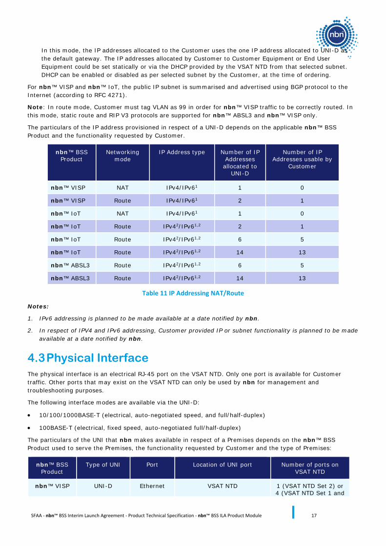
The particulars of the IP address provisioned in respect of a UNI-D depends on the applicable nbn™ BSS Product and the functionality requested by Customer.
nbn™ BSS Product
Networking mode
IP Address type Number of IP Addresses
allocated to UNI-D
Number of IP Addresses usable by
Customer
nbn™ VISP NAT IPv4/IPv61 1 0
nbn™ VISP Route IPv4/IPv61 2 1
nbn™ IoT NAT IPv4/IPv61 1 0
nbn™ IoT Route IPv42/IPv61,2 2 1
nbn™ IoT Route IPv42/IPv61,2 6 5
nbn™ IoT Route IPv42/IPv61,2 14 13
nbn™ ABSL3 Route IPv42/IPv61,2 6 5
nbn™ ABSL3 Route IPv42/IPv61,2 14 13
Table 11 IP Addressing NAT/Route
Notes:
1. IPv6 addressing is planned to be made available at a date notified by nbn.
2. In respect of IPV4 and IPv6 addressing, Customer provided IP or subnet functionality is planned to be made available at a date notified by nbn.
4.3 Physical Interface The physical interface is an electrical RJ-45 port on the VSAT NTD. Only one port is available for Customer traffic. Other ports that may exist on the VSAT NTD can only be used by nbn for management and troubleshooting purposes.
The following interface modes are available via the UNI-D:
• 10/100/1000BASE-T (electrical, auto-negotiated speed, and full/half-duplex)
• 100BASE-T (electrical, fixed speed, auto-negotiated full/half-duplex)
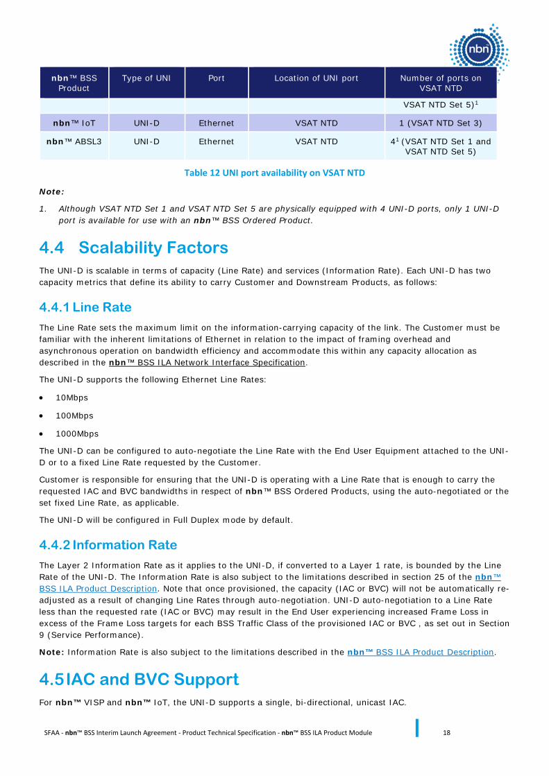
The particulars of the UNI that nbn makes available in respect of a Premises depends on the nbn™ BSS Product used to serve the Premises, the functionality requested by Customer and the type of Premises:
nbn™ BSS Product
Type of UNI Port Location of UNI port Number of ports on VSAT NTD
nbn™ VISP UNI-D Ethernet VSAT NTD 1 (VSAT NTD Set 2) or 4 (VSAT NTD Set 1 and
SFAA - nbn™ BSS Interim Launch Agreement - Product Technical Specification - nbn™ BSS ILA Product Module 18
nbn™ BSS Product
Type of UNI Port Location of UNI port Number of ports on VSAT NTD
VSAT NTD Set 5)1
nbn™ IoT UNI-D Ethernet VSAT NTD 1 (VSAT NTD Set 3)
nbn™ ABSL3 UNI-D Ethernet VSAT NTD 41 (VSAT NTD Set 1 and VSAT NTD Set 5)
Table 12 UNI port availability on VSAT NTD
Note:
1. Although VSAT NTD Set 1 and VSAT NTD Set 5 are physically equipped with 4 UNI-D ports, only 1 UNI-D port is available for use with an nbn™ BSS Ordered Product.
4.4 Scalability Factors The UNI-D is scalable in terms of capacity (Line Rate) and services (Information Rate). Each UNI-D has two capacity metrics that define its ability to carry Customer and Downstream Products, as follows:
4.4.1 Line Rate
The Line Rate sets the maximum limit on the information-carrying capacity of the link. The Customer must be familiar with the inherent limitations of Ethernet in relation to the impact of framing overhead and asynchronous operation on bandwidth efficiency and accommodate this within any capacity allocation as described in the nbn™ BSS ILA Network Interface Specification.
The UNI-D supports the following Ethernet Line Rates:
• 10Mbps
• 100Mbps
• 1000Mbps
The UNI-D can be configured to auto-negotiate the Line Rate with the End User Equipment attached to the UNI-D or to a fixed Line Rate requested by the Customer.
Customer is responsible for ensuring that the UNI-D is operating with a Line Rate that is enough to carry the requested IAC and BVC bandwidths in respect of nbn™ BSS Ordered Products, using the auto-negotiated or the set fixed Line Rate, as applicable.
The UNI-D will be configured in Full Duplex mode by default.
4.4.2 Information Rate
The Layer 2 Information Rate as it applies to the UNI-D, if converted to a Layer 1 rate, is bounded by the Line Rate of the UNI-D. The Information Rate is also subject to the limitations described in section 25 of the nbn™ BSS ILA Product Description. Note that once provisioned, the capacity (IAC or BVC) will not be automatically re-adjusted as a result of changing Line Rates through auto-negotiation. UNI-D auto-negotiation to a Line Rate less than the requested rate (IAC or BVC) may result in the End User experiencing increased Frame Loss in excess of the Frame Loss targets for each BSS Traffic Class of the provisioned IAC or BVC , as set out in Section 9 (Service Performance).
Note: Information Rate is also subject to the limitations described in the nbn™ BSS ILA Product Description.
4.5 IAC and BVC Support For nbn™ VISP and nbn™ IoT, the UNI-D supports a single, bi-directional, unicast IAC.
SFAA - nbn™ BSS Interim Launch Agreement - Product Technical Specification - nbn™ BSS ILA Product Module 19
For nbn™ ABSL3, the UNI-D supports a single, bi-directional, unicast BVC.
4.6 Resilience The UNI-D is an unprotected physical interface. If an unprotected UNI-D suffers a failure, all services being delivered across that UNI-D will be disrupted.
4.7 VSAT NTD Supply nbn will supply VSAT NTDs suitable for operation with each nbn™ BSS Product and based on Customer requirements.
The VSAT NTD includes the following nbn approved elements:
• An outdoor unit (ODU), being the transceiver and the antenna; and
• An indoor unit (IDU), being the modem.
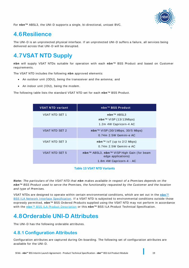
The following table lists the standard VSAT NTD set for each nbn™ BSS Product.
VSAT NTD variant nbn™ BSS Product
VSAT NTD SET 1 nbn™ ABSL3 nbn™ VISP (13/13Mbps) 1.2m 4W Capricorn-4 AC
VSAT NTD SET 2 nbn™ VISP (30/1Mbps, 30/5 Mbps) 0.74m 2.5W Gemini-e AC
VSAT NTD SET 3 nbn™ IoT (up to 2/2 Mbps) 0.74m 2.5W Gemini-e AC
VSAT NTD SET 5 nbn™ ABSL3, nbn™ VISP High Gain (for beam edge applications)
1.8m 4W Capricorn-4 - AC
Table 13 VSAT NTD Variants
Note: The particulars of the VSAT NTD that nbn makes available in respect of a Premises depends on the nbn™ BSS Product used to serve the Premises, the functionality requested by the Customer and the location and type of Premises.
VSAT NTDs are designed to operate within certain environmental conditions, which are set out in the nbn™ BSS ILA Network Interface Specification. If a VSAT NTD is subjected to environmental conditions outside those expressly permitted, nbn™ BSS Ordered Products supplied using the VSAT NTD may not perform in accordance with the nbn™ BSS ILA Product Description or this nbn™ BSS ILA Product Technical Specification.
4.8 Orderable UNI-D Attributes The UNI-D has the following orderable attributes.
4.8.1 Configuration Attributes
Configuration attributes are captured during On-boarding. The following set of configuration attributes are available for the UNI-D.
SFAA - nbn™ BSS Interim Launch Agreement - Product Technical Specification - nbn™ BSS ILA Product Module 20
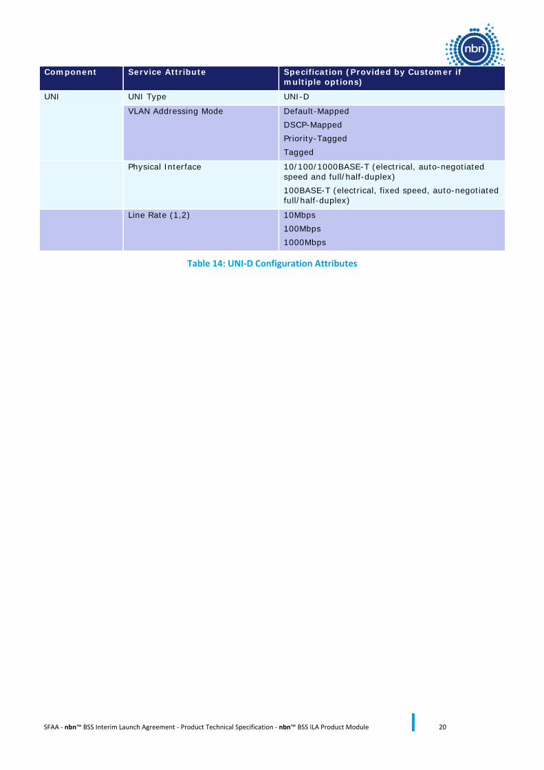
Component Service Attribute Specification (Provided by Customer if multiple options)
UNI UNI Type UNI-D
VLAN Addressing Mode Default-Mapped DSCP-Mapped Priority-Tagged Tagged
Physical Interface 10/100/1000BASE-T (electrical, auto-negotiated speed and full/half-duplex) 100BASE-T (electrical, fixed speed, auto-negotiated full/half-duplex)
Line Rate (1,2) 10Mbps 100Mbps 1000Mbps
Table 14: UNI-D Configuration Attributes
SFAA - nbn™ BSS Interim Launch Agreement - Product Technical Specification - nbn™ BSS ILA Product Module 21
5 Broadband Virtual Connection (BVC)
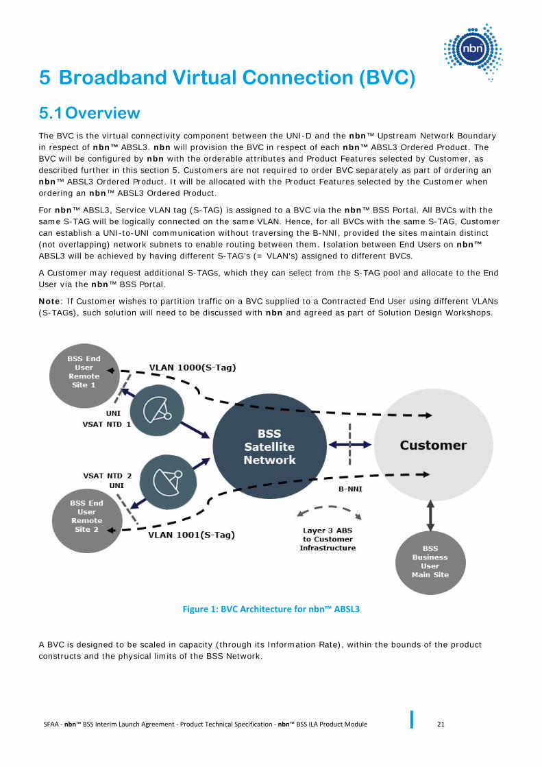
5.1 Overview The BVC is the virtual connectivity component between the UNI-D and the nbn™ Upstream Network Boundary in respect of nbn™ ABSL3. nbn will provision the BVC in respect of each nbn™ ABSL3 Ordered Product. The BVC will be configured by nbn with the orderable attributes and Product Features selected by Customer, as described further in this section 5. Customers are not required to order BVC separately as part of ordering an nbn™ ABSL3 Ordered Product. It will be allocated with the Product Features selected by the Customer when ordering an nbn™ ABSL3 Ordered Product.
For nbn™ ABSL3, Service VLAN tag (S-TAG) is assigned to a BVC via the nbn™ BSS Portal. All BVCs with the same S-TAG will be logically connected on the same VLAN. Hence, for all BVCs with the same S-TAG, Customer can establish a UNI-to-UNI communication without traversing the B-NNI, provided the sites maintain distinct (not overlapping) network subnets to enable routing between them. Isolation between End Users on nbn™ ABSL3 will be achieved by having different S-TAG’s (= VLAN’s) assigned to different BVCs.
A Customer may request additional S-TAGs, which they can select from the S-TAG pool and allocate to the End User via the nbn™ BSS Portal.
Note: If Customer wishes to partition traffic on a BVC supplied to a Contracted End User using different VLANs (S-TAGs), such solution will need to be discussed with nbn and agreed as part of Solution Design Workshops.
Figure 1: BVC Architecture for nbn™ ABSL3
A BVC is designed to be scaled in capacity (through its Information Rate), within the bounds of the product constructs and the physical limits of the BSS Network.
SFAA - nbn™ BSS Interim Launch Agreement - Product Technical Specification - nbn™ BSS ILA Product Module 22
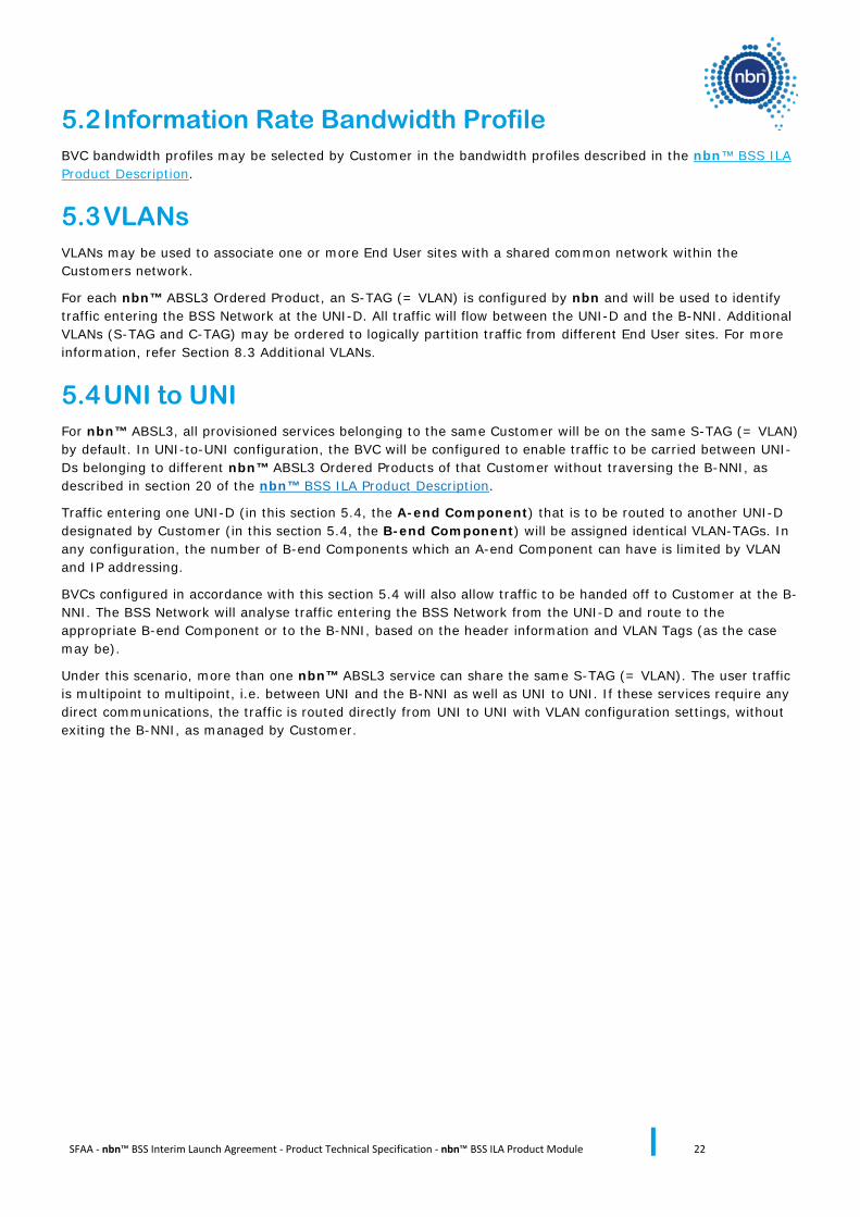
5.2 Information Rate Bandwidth Profile BVC bandwidth profiles may be selected by Customer in the bandwidth profiles described in the nbn™ BSS ILA Product Description.
5.3 VLANs VLANs may be used to associate one or more End User sites with a shared common network within the Customers network.
For each nbn™ ABSL3 Ordered Product, an S-TAG (= VLAN) is configured by nbn and will be used to identify traffic entering the BSS Network at the UNI-D. All traffic will flow between the UNI-D and the B-NNI. Additional VLANs (S-TAG and C-TAG) may be ordered to logically partition traffic from different End User sites. For more information, refer Section 8.3 Additional VLANs.
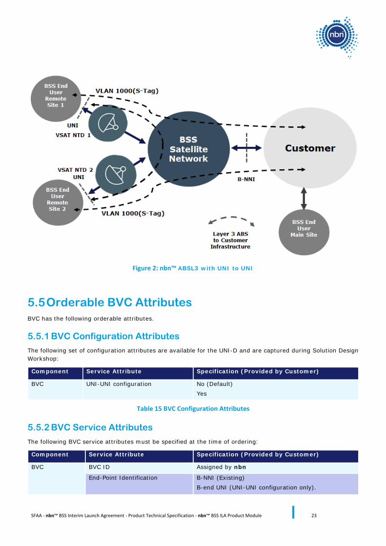
5.4 UNI to UNI For nbn™ ABSL3, all provisioned services belonging to the same Customer will be on the same S-TAG (= VLAN) by default. In UNI-to-UNI configuration, the BVC will be configured to enable traffic to be carried between UNI-Ds belonging to different nbn™ ABSL3 Ordered Products of that Customer without traversing the B-NNI, as described in section 20 of the nbn™ BSS ILA Product Description.
Traffic entering one UNI-D (in this section 5.4, the A-end Component) that is to be routed to another UNI-D designated by Customer (in this section 5.4, the B-end Component) will be assigned identical VLAN-TAGs. In any configuration, the number of B-end Components which an A-end Component can have is limited by VLAN and IP addressing.
BVCs configured in accordance with this section 5.4 will also allow traffic to be handed off to Customer at the B-NNI. The BSS Network will analyse traffic entering the BSS Network from the UNI-D and route to the appropriate B-end Component or to the B-NNI, based on the header information and VLAN Tags (as the case may be).
Under this scenario, more than one nbn™ ABSL3 service can share the same S-TAG (= VLAN). The user traffic is multipoint to multipoint, i.e. between UNI and the B-NNI as well as UNI to UNI. If these services require any direct communications, the traffic is routed directly from UNI to UNI with VLAN configuration settings, without exiting the B-NNI, as managed by Customer.
SFAA - nbn™ BSS Interim Launch Agreement - Product Technical Specification - nbn™ BSS ILA Product Module 23
Figure 2: nbn™ ABSL3 with UNI to UNI
5.5 Orderable BVC Attributes BVC has the following orderable attributes.
5.5.1 BVC Configuration Attributes
The following set of configuration attributes are available for the UNI-D and are captured during Solution Design Workshop:
Component Service Attribute Specification (Provided by Customer)
BVC UNI-UNI configuration No (Default) Yes
Table 15 BVC Configuration Attributes
5.5.2 BVC Service Attributes
The following BVC service attributes must be specified at the time of ordering:
Component Service Attribute Specification (Provided by Customer)
BVC BVC ID Assigned by nbn
End-Point Identification B-NNI (Existing) B-end UNI (UNI-UNI configuration only).
SFAA - nbn™ BSS Interim Launch Agreement - Product Technical Specification - nbn™ BSS ILA Product Module 24
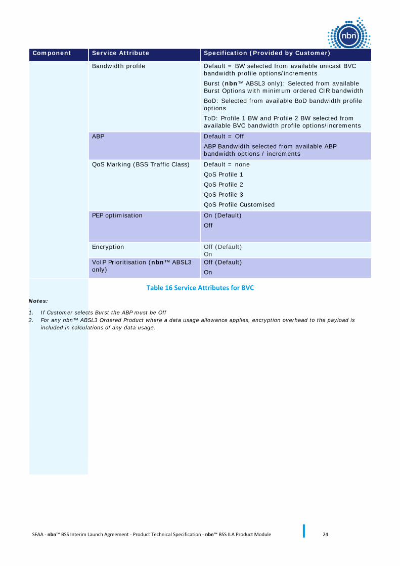
Component Service Attribute Specification (Provided by Customer)
Bandwidth profile Default = BW selected from available unicast BVC bandwidth profile options/increments Burst (nbn™ ABSL3 only): Selected from available Burst Options with minimum ordered CIR bandwidth BoD: Selected from available BoD bandwidth profile options ToD: Profile 1 BW and Profile 2 BW selected from available BVC bandwidth profile options/increments
ABP Default = Off ABP Bandwidth selected from available ABP bandwidth options / increments
QoS Marking (BSS Traffic Class) Default = none QoS Profile 1 QoS Profile 2 QoS Profile 3 QoS Profile Customised
PEP optimisation On (Default) Off
Encryption Off (Default) On
VoIP Prioritisation (nbn™ ABSL3 only)
Off (Default) On
Table 16 Service Attributes for BVC
Notes:
1. If Customer selects Burst the ABP must be Off 2. For any nbn™ ABSL3 Ordered Product where a data usage allowance applies, encryption overhead to the payload is
included in calculations of any data usage.
SFAA - nbn™ BSS Interim Launch Agreement - Product Technical Specification - nbn™ BSS ILA Product Module 25
6 Internet Access Connection (IAC)
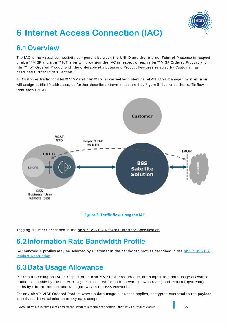
6.1 Overview The IAC is the virtual connectivity component between the UNI-D and the Internet Point of Presence in respect of nbn™ VISP and nbn™ IoT. nbn will provision the IAC in respect of each nbn™ VISP Ordered Product and nbn™ IoT Ordered Product with the orderable attributes and Product Features selected by Customer, as described further in this Section 6.
All Customer traffic for nbn™ VISP and nbn™ IoT is carried with identical VLAN TAGs managed by nbn. nbn will assign public IP addresses, as further described above in section 4.1. Figure 3 illustrates the traffic flow from each UNI-D.
Figure 3: Traffic flow along the IAC
Tagging is further described in the nbn™ BSS ILA Network Interface Specification.
6.2 Information Rate Bandwidth Profile IAC bandwidth profiles may be selected by Customer in the bandwidth profiles described in the nbn™ BSS ILA Product Description.
6.3 Data Usage Allowance Packets traversing an IAC in respect of an nbn™ VISP Ordered Product are subject to a data usage allowance profile, selectable by Customer. Usage is calculated for both Forward (downstream) and Return (upstream) paths by nbn at the east and west gateway in the BSS Network.
For any nbn™ VISP Ordered Product where a data usage allowance applies, encrypted overhead to the payload is excluded from calculation of any data usage.
SFAA - nbn™ BSS Interim Launch Agreement - Product Technical Specification - nbn™ BSS ILA Product Module 26
The VSAT NTD and DPS are responsible for encryption key management which is transparent to the End User. AES encryption over the air adds on average 12.5 bytes header to the data packet. See further section 8.6.
6.4 Orderable IAC Attributes IAC has the following orderable attributes.
6.4.1 IAC Configuration Attributes
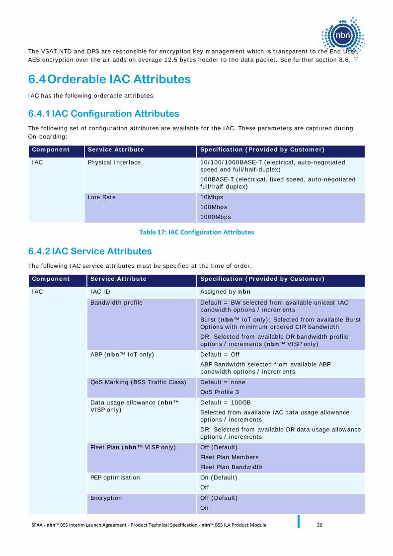
The following set of configuration attributes are available for the IAC. These parameters are captured during On-boarding:
Component Service Attribute Specification (Provided by Customer)
IAC Physical Interface 10/100/1000BASE-T (electrical, auto-negotiated speed and full/half-duplex) 100BASE-T (electrical, fixed speed, auto-negotiated full/half-duplex)
Line Rate 10Mbps 100Mbps 1000Mbps
Table 17: IAC Configuration Attributes
6.4.2 IAC Service Attributes
The following IAC service attributes must be specified at the time of order:
Component Service Attribute Specification (Provided by Customer)
IAC IAC ID Assigned by nbn
Bandwidth profile Default = BW selected from available unicast IAC bandwidth options / increments Burst (nbn™ IoT only): Selected from available Burst Options with minimum ordered CIR bandwidth DR: Selected from available DR bandwidth profile options / increments (nbn™ VISP only)
ABP (nbn™ IoT only) Default = Off ABP Bandwidth selected from available ABP bandwidth options / increments
QoS Marking (BSS Traffic Class) Default = none QoS Profile 3
Data usage allowance (nbn™ VISP only)
Default = 100GB Selected from available IAC data usage allowance options / increments DR: Selected from available DR data usage allowance options / increments
Fleet Plan (nbn™ VISP only) Off (Default) Fleet Plan Members Fleet Plan Bandwidth
PEP optimisation On (Default) Off
Encryption Off (Default) On

SFAA - nbn™ BSS Interim Launch Agreement - Product Technical Specification - nbn™ BSS ILA Product Module 27
VoIP Prioritisation (nbn™ VISP only)
Off (Default) On
Table 18 Service Attributes for IAC
SFAA - nbn™ BSS Interim Launch Agreement - Product Technical Specification - nbn™ BSS ILA Product Module 28
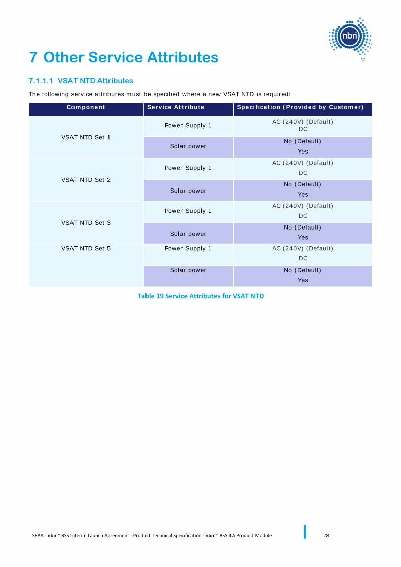
7 Other Service Attributes 7.1.1.1 VSAT NTD Attributes
The following service attributes must be specified where a new VSAT NTD is required:
Component Service Attribute Specification (Provided by Customer)
VSAT NTD Set 1
Power Supply 1 AC (240V) (Default) DC
Solar power No (Default)
Yes
VSAT NTD Set 2
Power Supply 1 AC (240V) (Default)
DC
Solar power No (Default)
Yes
VSAT NTD Set 3
Power Supply 1 AC (240V) (Default)
DC
Solar power No (Default)
Yes
VSAT NTD Set 5 Power Supply 1 AC (240V) (Default) DC
Solar power No (Default) Yes
Table 19 Service Attributes for VSAT NTD
SFAA - nbn™ BSS Interim Launch Agreement - Product Technical Specification - nbn™ BSS ILA Product Module 29
8 Product Features A number of Product Features will be made available to Customer, the availability of which is determined in accordance to the nbn™ BSS ILA Product Description.
8.1 Access Bandwidth Pool (ABP) Access Bandwidth Pool allows Customer to order a pool of bandwidth that can be allocated (in respect of any CIR bandwidth) or shared on a contended basis (in respect of any PIR bandwidth) across multiple Ordered Products (ABP Members). Customer can manage contention between the Ordered Products (ABP Members) which operate in the same ABP, thus enabling better efficiency in respect of bandwidth utilisation. The ABP Product Feature applies only to the eligible nbn™ BSS Products; nbn™ IoT and nbn™ ABSL3.
Each ABP will only service one type of nbn™ BSS Product. Separate ABPs are required for each type of nbn™ BSS Product set, nbn™ IoT or nbn™ ASBL3 respectively. The ABP must be ordered separately (established), ahead of or at the time of purchasing the Ordered Products that will be operating within the ABP.
Customer may order ABP capacity for use in either a single Beam or multiple designated Beams. The selected Beams define the Customers’ ordered ABP coverage area. The Beams define the geographical areas to which Ordered Products in an ABP can be supplied. The ABP must be configured with a common QoS Marking (if selected) and is reported as a single block of capacity.
Note: all services in the ABP must operate the same QoS Marking.
Dedicated CIR bandwidth will be delivered using bandwidth allocated in respect of Customer in a Beam. PIR bandwidth will be delivered using bandwidth shared between Customer and Other Customers (and managed by nbn).
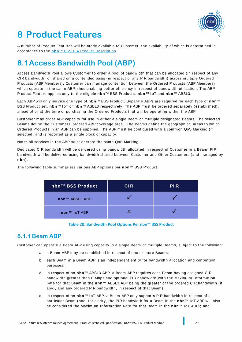
The following table summarises various ABP options per nbn™ BSS Product.
nbn™ BSS Product CIR PIR
nbn™ ABSL3 ABP
nbn™ IoT ABP
Table 20: Bandwidth Pool Options Per nbn™ BSS Product
8.1.1 Beam ABP
Customer can operate a Beam ABP using capacity in a single Beam or multiple Beams, subject to the following:
a. a Beam ABP may be established in respect of one or more Beams;
b. each Beam in a Beam ABP is an independent entity for bandwidth allocation and contention purposes;
c. in respect of an nbn™ ABSL3 ABP, a Beam ABP requires each Beam having assigned CIR bandwidth greater than 0 Mbps and optional PIR bandwidth(with the Maximum Information Rate for that Beam in the nbn™ ABSL3 ABP being the greater of the ordered CIR bandwidth (if any), and any ordered PIR bandwidth, in respect of that Beam);
d. in respect of an nbn™ IoT ABP, a Beam ABP only supports PIR bandwidth in respect of a particular Beam (and, for clarity, the PIR bandwidth for a Beam in the nbn™ IoT ABP will also be considered the Maximum Information Rate for that Beam in the nbn™ IoT ABP); and
SFAA - nbn™ BSS Interim Launch Agreement - Product Technical Specification - nbn™ BSS ILA Product Module 30
e. the bandwidth in a Beam cannot be shared between ABP Members in other Beams within the Beam ABP.
Note: ABP operating as capacity for a group of services across a number of Beams is planned to be made available at a date notified by nbn.
Customer may separately order nbn™ BSS Ordered Products in a single Beam within the ABP. Each of the Ordered Products in the ABP will have their own bandwidth profile of CIR (in respect of nbn™ ABSL3 ABP Members) and PIR as may be configured by Customer in accordance with section 7 of the nbn™ BSS ILA Product Description. Customer will be able to allocate any CIR bandwidth, or share any PIR bandwidth on a contended basis (as the case may be), ordered in a Beam ABP between the ABP Members operating in that Beam.
If more than one Ordered Product is in operation in a single Beam within an ABP, those Ordered Products will be allocated any CIR bandwidth, or share any PIR bandwidth on a contended basis (as the case may be), within the Beam bandwidth in that ABP. Customer is responsible for managing the dimensioning of capacity, and bandwidth contention (if applicable), between the ABP Members within a Beam.
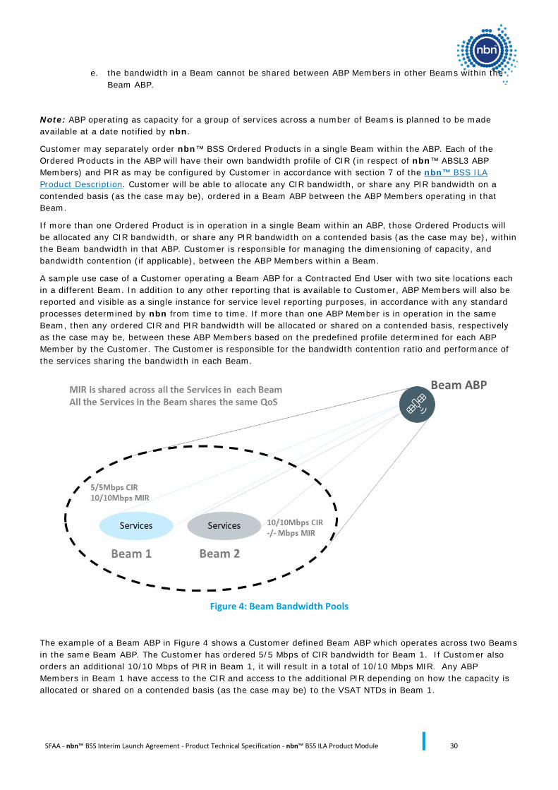
A sample use case of a Customer operating a Beam ABP for a Contracted End User with two site locations each in a different Beam. In addition to any other reporting that is available to Customer, ABP Members will also be reported and visible as a single instance for service level reporting purposes, in accordance with any standard processes determined by nbn from time to time. If more than one ABP Member is in operation in the same Beam, then any ordered CIR and PIR bandwidth will be allocated or shared on a contended basis, respectively as the case may be, between these ABP Members based on the predefined profile determined for each ABP Member by the Customer. The Customer is responsible for the bandwidth contention ratio and performance of the services sharing the bandwidth in each Beam.
Figure 4: Beam Bandwidth Pools
The example of a Beam ABP in Figure 4 shows a Customer defined Beam ABP which operates across two Beams in the same Beam ABP. The Customer has ordered 5/5 Mbps of CIR bandwidth for Beam 1. If Customer also orders an additional 10/10 Mbps of PIR in Beam 1, it will result in a total of 10/10 Mbps MIR. Any ABP Members in Beam 1 have access to the CIR and access to the additional PIR depending on how the capacity is allocated or shared on a contended basis (as the case may be) to the VSAT NTDs in Beam 1.
SFAA - nbn™ BSS Interim Launch Agreement - Product Technical Specification - nbn™ BSS ILA Product Module 31
In Beam 2 of the Beam ABP the Customer has ordered CIR of 10/10Mbps. No additional PIR capacity has been ordered for Beam 2. In this instance the CIR is capacity that is always available to be allocated between ABP Members located in Beam 2. As no PIR has been ordered in Beam 2 of the ABP, the ABP Members do not have access to ABP PIR so the MIR is equal to the CIR of 10/10Mbps.
8.2 Burst Burst is an optional Product Feature of the BVC Product Component only in respect of nbn™ ABSL3.
Burst provides an nbn™ ABSL3 BVC Ordered Product at predefined CIR thresholds the limited ability to burst above its CIR in accordance with the associated Burst profiles, on a best efforts basis Burst is only available in respect of nbn™ ABSL3 BSS Ordered Products not operating in an ABP.
The Burst profiles and thresholds are:
Burst Profile CIR threshold
(Forward/Return) Mbps (minimum)
Maximum Burst achievable PIR Forward (Mbps)
Profile 1 1/1 10
Profile 2 2/1 20
Profile 3 5/1 50
Table 21: Burst profiles and thresholds
Customer may select a Burst profile only in respect of an nbn™ ABSL3 Ordered Product that meets or exceeds the associated CIR threshold. For example, an nbn™ ABSL3 BVC with 4/1 Mbps (CIR) is eligible for Burst “Profile 1” (10 Mbps PIR Forward) and Burst “Profile 2” (20 Mbps PIR Forward).
In another example, if Customer acquires the Burst “Profile 2” option with an nbn™ ABSL3 BVC Ordered Product with 2/1 Mbps (CIR), the nbn™ ABSL3 Ordered Product can burst up to a maximum of 2 Mbps CIR – 20 Mbps PIR / 1 Mbps CIR.
8.3 Additional VLANs Additional VLANs enable Customers to logically separate traffic from different End User sites.
An nbn™ ABSL3 BVC is configured with a single VLAN. In this construct VLAN (S-TAG) can represent a group of End User sites (of the same enterprise) such that all these sites are logically partitioned from other traffic generated by other End Users of the same Customer. The Customer may order up to 4 additional VLANs for each such group of End User sites.
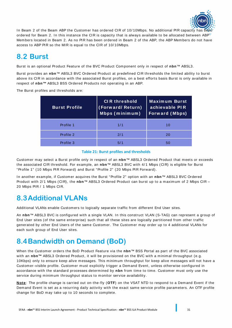
8.4 Bandwidth on Demand (BoD) When the Customer orders the BoD Product Feature via the nbn™ BSS Portal as part of the BVC associated with an nbn™ ABSL3 Ordered Product, it will be provisioned on the BVC with a minimal throughput (e.g. 10Kbps) only to ensure keep alive messages. This minimum throughput for keep alive messages will not have a Customer-visible profile. Customer must explicitly trigger a Demand Event, unless otherwise configured in accordance with the standard processes determined by nbn from time to time. Customer must only use the service during minimum throughput status to monitor service availability.
Note: The profile change is carried out on-the-fly (OTF) on the VSAT NTD to respond to a Demand Event if the Demand Event is set as a recurring daily activity with the exact same service profile parameters. An OTF profile change for BoD may take up to 10 seconds to complete.
SFAA - nbn™ BSS Interim Launch Agreement - Product Technical Specification - nbn™ BSS ILA Product Module 32
Figure 5: Example BoD configuration
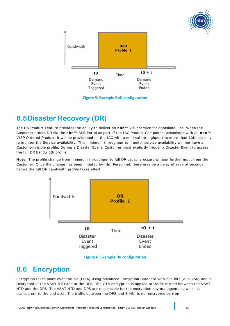
8.5 Disaster Recovery (DR) The DR Product Feature provides the ability to deliver an nbn™ VISP service for occasional use. When the Customer orders DR via the nbn™ BSS Portal as part of the IAC Product Component associated with an nbn™ VISP Ordered Product, it will be provisioned on the IAC with a minimal throughput (no more than 10Kbps) only to monitor the Service availability. This minimum throughput to monitor service availability will not have a Customer-visible profile. During a Disaster Event, Customer must explicitly trigger a Disaster Event to access the full DR bandwidth profile.
Note: The profile change from minimum throughput to full DR capacity occurs without further input from the Customer. Once the change has been initiated by nbn Personnel, there may be a delay of several seconds before the full DR bandwidth profile takes effect.
Figure 6: Example DR configuration
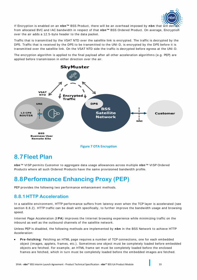
8.6 Encryption Encryption takes place over-the-air (OTA) using Advanced Encryption Standard with 256 bits (AES-256) and is Decrypted at the VSAT NTD and at the DPS. The OTA encryption is applied to traffic carried between the VSAT NTD and the DPS. The VSAT NTD and DPS are responsible for the encryption key management, which is transparent to the end user. The traffic between the DPS and B-NNI is not encrypted by nbn.
SFAA - nbn™ BSS Interim Launch Agreement - Product Technical Specification - nbn™ BSS ILA Product Module 33
If Encryption is enabled on an nbn™ BSS Product, there will be an overhead imposed by nbn that will detract from allocated BVC and IAC bandwidth in respect of that nbn™ BSS Ordered Product. On average, Encryption over the air adds a 12.5-byte header to the data packet.
Traffic that is transmitted by the VSAT NTD over the satellite link is encrypted. The traffic is decrypted by the DPS. Traffic that is received by the DPS to be transmitted to the UNI-D, is encrypted by the DPS before it is transmitted over the satellite link. On the VSAT NTD side the traffic is decrypted before egress at the UNI-D.
The encryption algorithm is applied to the final payload after all other acceleration algorithms (e.g. PEP) are applied before transmission in either direction over the air.
Figure 7 OTA Encryption
8.7 Fleet Plan nbn™ VISP permits Customer to aggregate data usage allowances across multiple nbn™ VISP Ordered Products where all such Ordered Products have the same provisioned bandwidth profile.
8.8 Performance Enhancing Proxy (PEP) PEP provides the following two performance enhancement methods.
8.8.1 HTTP Acceleration
In a satellite environment, HTTP performance suffers from latency even when the TCP layer is accelerated (see section 8.8.2). HTTP traffic can be dealt with specifically, to further improve the bandwidth usage and browsing speed.
Internet Page Acceleration (IPA) improves the Internet browsing experience while minimizing traffic on the inbound as well as the outbound channels of the satellite network.
Unless PEP is disabled, the following methods are implemented by nbn in the BSS Network to achieve HTTP Acceleration:
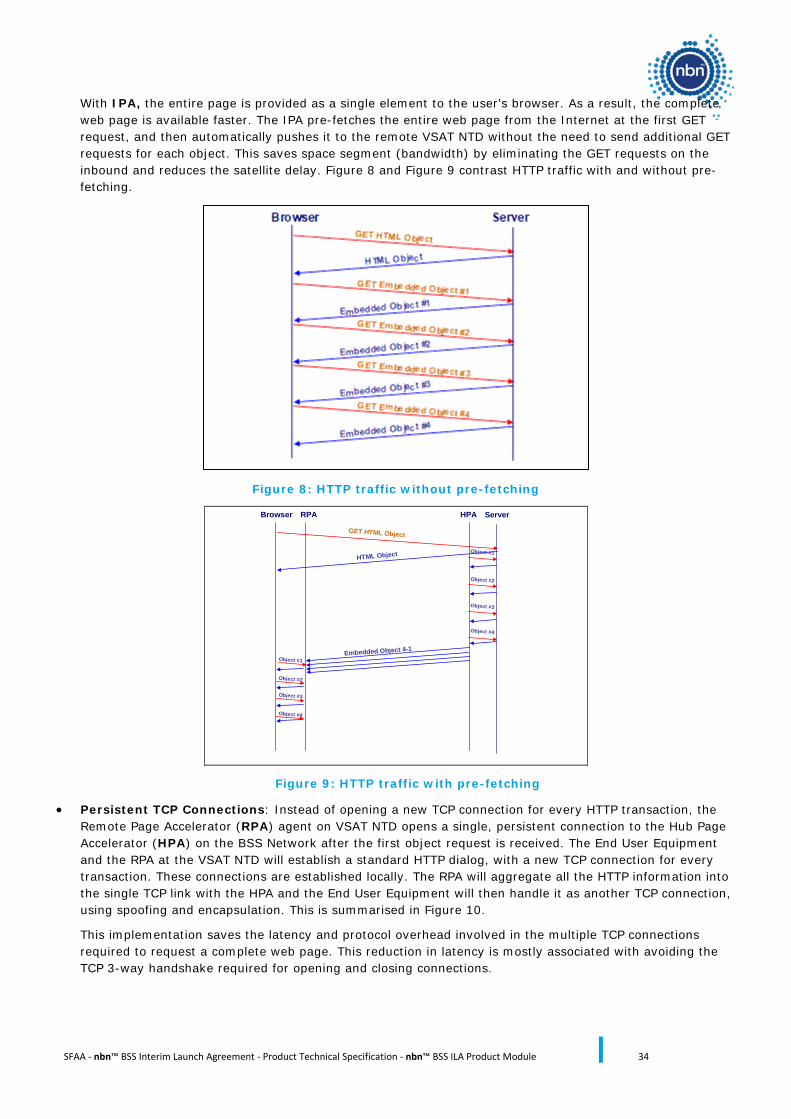
• Pre-fetching: Fetching an HTML page requires a number of TCP connections, one for each embedded object (images, applets, frames, etc.). Sometimes one object must be completely loaded before embedded objects are fetched. For example, an HTML frame set must be completely loaded before the enclosed frames are fetched, which in turn must be completely loaded before the embedded images are fetched.
SFAA - nbn™ BSS Interim Launch Agreement - Product Technical Specification - nbn™ BSS ILA Product Module 34
With IPA, the entire page is provided as a single element to the user’s browser. As a result, the complete web page is available faster. The IPA pre-fetches the entire web page from the Internet at the first GET request, and then automatically pushes it to the remote VSAT NTD without the need to send additional GET requests for each object. This saves space segment (bandwidth) by eliminating the GET requests on the inbound and reduces the satellite delay. Figure 8 and Figure 9 contrast HTTP traffic with and without pre-fetching.
Figure 8: HTTP traffic without pre-fetching
Server
GET HTML Object
HTML Object
Browser RPA HPA
Embedded Object 4-1Object #1
Object #2
Object #3
Object #4
Object #1
Object #2
Object #3
Object #4
Figure 9: HTTP traffic with pre-fetching
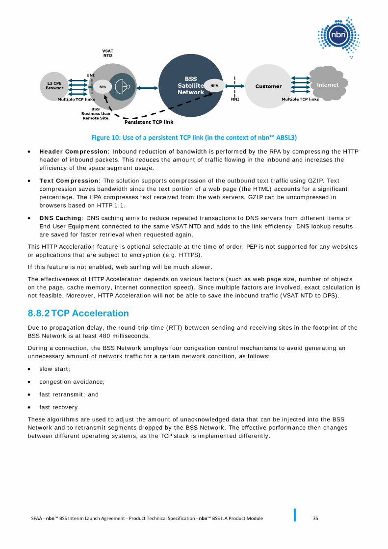
• Persistent TCP Connections: Instead of opening a new TCP connection for every HTTP transaction, the Remote Page Accelerator (RPA) agent on VSAT NTD opens a single, persistent connection to the Hub Page Accelerator (HPA) on the BSS Network after the first object request is received. The End User Equipment and the RPA at the VSAT NTD will establish a standard HTTP dialog, with a new TCP connection for every transaction. These connections are established locally. The RPA will aggregate all the HTTP information into the single TCP link with the HPA and the End User Equipment will then handle it as another TCP connection, using spoofing and encapsulation. This is summarised in Figure 10.
This implementation saves the latency and protocol overhead involved in the multiple TCP connections required to request a complete web page. This reduction in latency is mostly associated with avoiding the TCP 3-way handshake required for opening and closing connections.
SFAA - nbn™ BSS Interim Launch Agreement - Product Technical Specification - nbn™ BSS ILA Product Module 35
Figure 10: Use of a persistent TCP link (in the context of nbn™ ABSL3)
• Header Compression: Inbound reduction of bandwidth is performed by the RPA by compressing the HTTP header of inbound packets. This reduces the amount of traffic flowing in the inbound and increases the efficiency of the space segment usage.
• Text Compression: The solution supports compression of the outbound text traffic using GZIP. Text compression saves bandwidth since the text portion of a web page (the HTML) accounts for a significant percentage. The HPA compresses text received from the web servers. GZIP can be uncompressed in browsers based on HTTP 1.1.
• DNS Caching: DNS caching aims to reduce repeated transactions to DNS servers from different items of End User Equipment connected to the same VSAT NTD and adds to the link efficiency. DNS lookup results are saved for faster retrieval when requested again.
This HTTP Acceleration feature is optional selectable at the time of order. PEP is not supported for any websites or applications that are subject to encryption (e.g. HTTPS).
If this feature is not enabled, web surfing will be much slower.
The effectiveness of HTTP Acceleration depends on various factors (such as web page size, number of objects on the page, cache memory, internet connection speed). Since multiple factors are involved, exact calculation is not feasible. Moreover, HTTP Acceleration will not be able to save the inbound traffic (VSAT NTD to DPS).
8.8.2 TCP Acceleration
Due to propagation delay, the round-trip-time (RTT) between sending and receiving sites in the footprint of the BSS Network is at least 480 milliseconds.
During a connection, the BSS Network employs four congestion control mechanisms to avoid generating an unnecessary amount of network traffic for a certain network condition, as follows:
• slow start;
• congestion avoidance;
• fast retransmit; and
• fast recovery.
These algorithms are used to adjust the amount of unacknowledged data that can be injected into the BSS Network and to retransmit segments dropped by the BSS Network. The effective performance then changes between different operating systems, as the TCP stack is implemented differently.
SFAA - nbn™ BSS Interim Launch Agreement - Product Technical Specification - nbn™ BSS ILA Product Module 36
SYNC
ACK
TCP1
TCP2
TCP3
TCP4
ACK
FIN
ACK
SYNC (Source IP-Add, Port, Dest1, PA-Add, Port, Socket)
ACK (Socket)
ACK1
ACK2
ACK3
ACK4
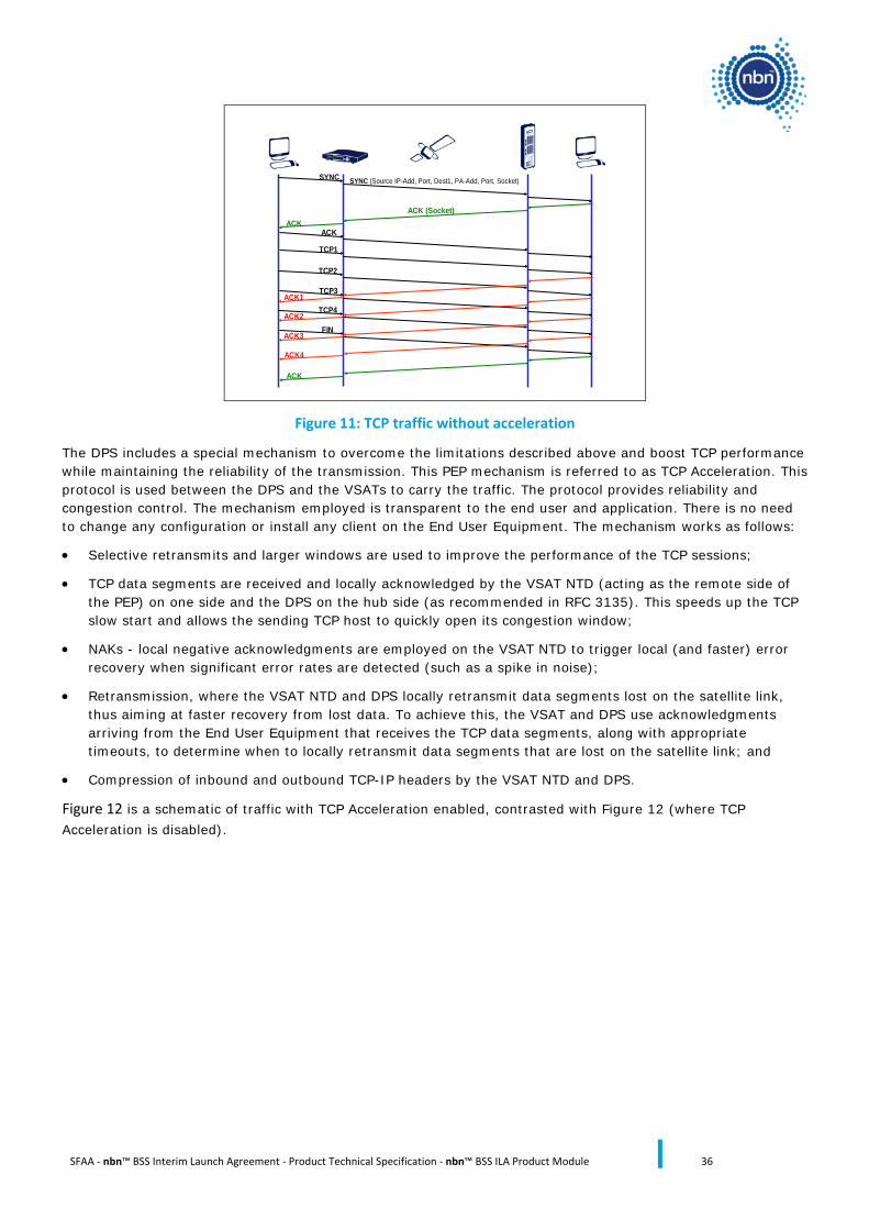
Figure 11: TCP traffic without acceleration
The DPS includes a special mechanism to overcome the limitations described above and boost TCP performance while maintaining the reliability of the transmission. This PEP mechanism is referred to as TCP Acceleration. This protocol is used between the DPS and the VSATs to carry the traffic. The protocol provides reliability and congestion control. The mechanism employed is transparent to the end user and application. There is no need to change any configuration or install any client on the End User Equipment. The mechanism works as follows:
• Selective retransmits and larger windows are used to improve the performance of the TCP sessions;
• TCP data segments are received and locally acknowledged by the VSAT NTD (acting as the remote side of the PEP) on one side and the DPS on the hub side (as recommended in RFC 3135). This speeds up the TCP slow start and allows the sending TCP host to quickly open its congestion window;
• NAKs - local negative acknowledgments are employed on the VSAT NTD to trigger local (and faster) error recovery when significant error rates are detected (such as a spike in noise);
• Retransmission, where the VSAT NTD and DPS locally retransmit data segments lost on the satellite link, thus aiming at faster recovery from lost data. To achieve this, the VSAT and DPS use acknowledgments arriving from the End User Equipment that receives the TCP data segments, along with appropriate timeouts, to determine when to locally retransmit data segments that are lost on the satellite link; and
• Compression of inbound and outbound TCP-IP headers by the VSAT NTD and DPS.
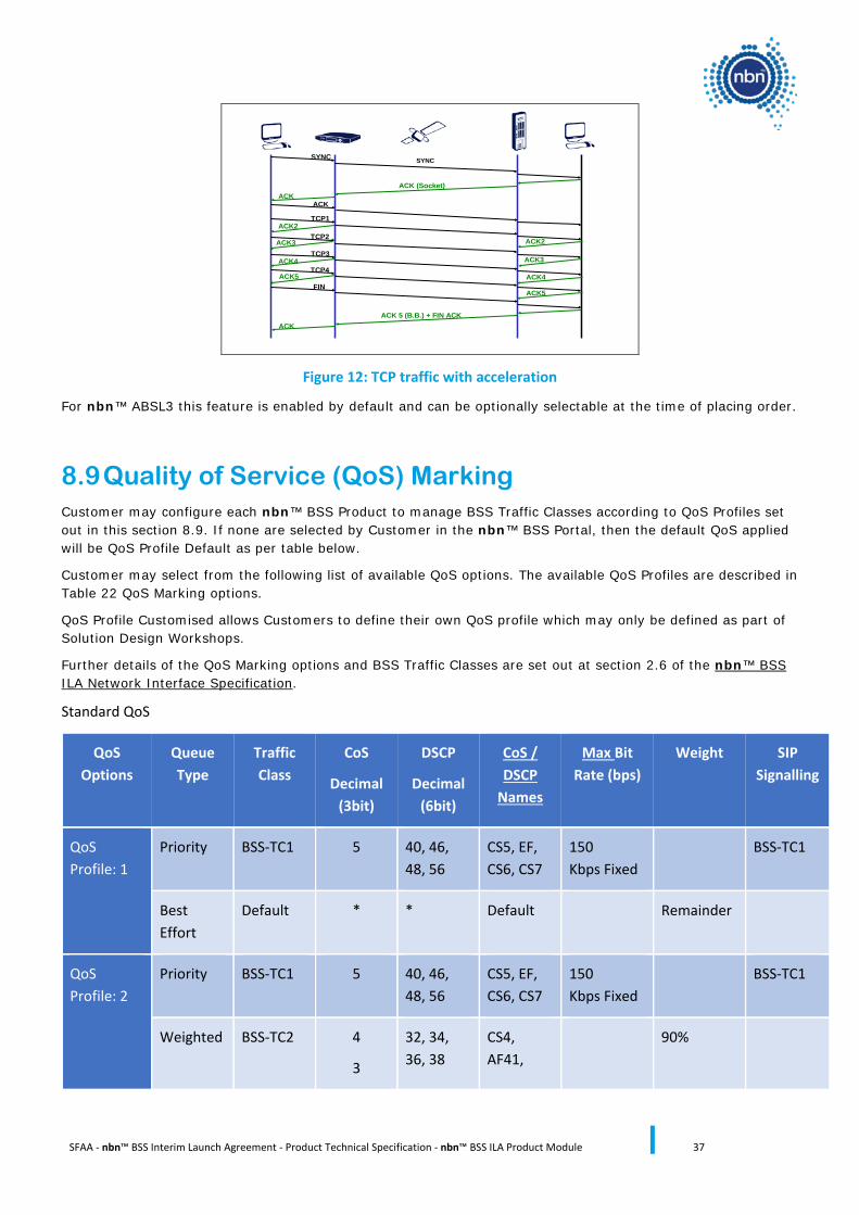
Figure 12 is a schematic of traffic with TCP Acceleration enabled, contrasted with Figure 12 (where TCP Acceleration is disabled).
SFAA - nbn™ BSS Interim Launch Agreement - Product Technical Specification - nbn™ BSS ILA Product Module 37
SYNC
ACK
TCP1
TCP2
TCP3
TCP4
ACK
FIN
ACK
ACK (Socket)
ACK3
ACK2
ACK4
ACK5
ACK 5 (B.B.) + FIN ACK
ACK2
ACK3ACK4
ACK5
SYNC
Figure 12: TCP traffic with acceleration
For nbn™ ABSL3 this feature is enabled by default and can be optionally selectable at the time of placing order.
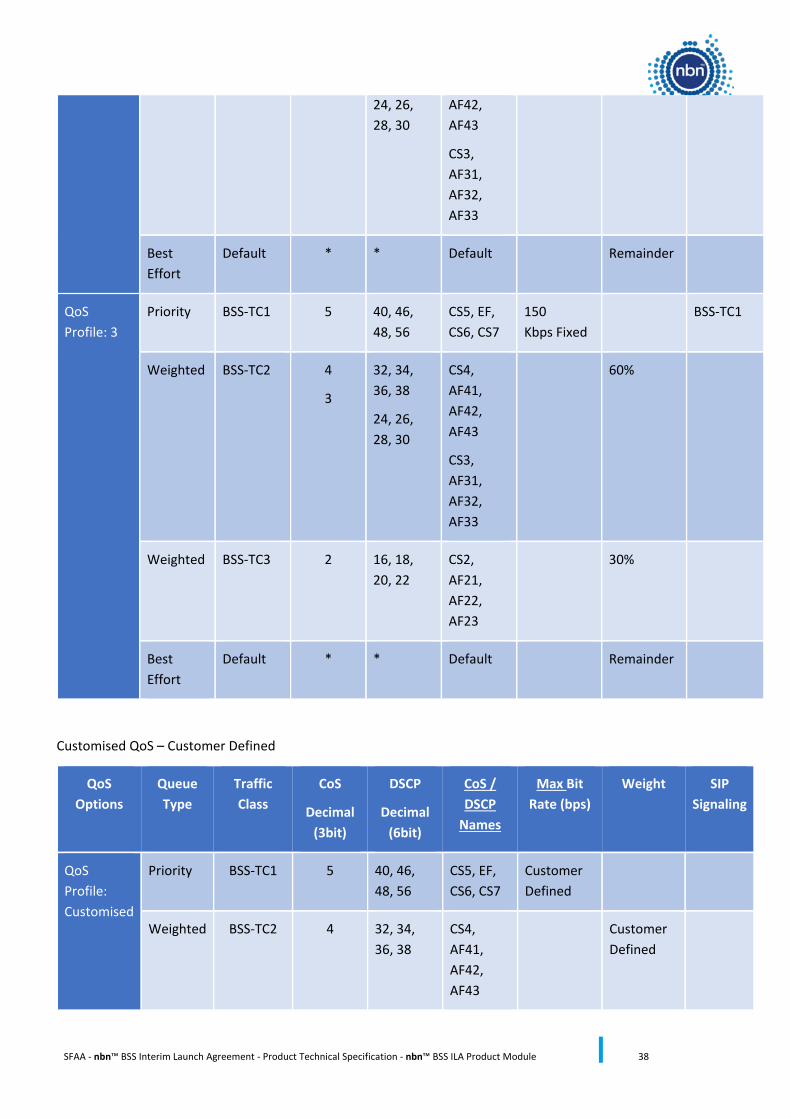
8.9 Quality of Service (QoS) Marking Customer may configure each nbn™ BSS Product to manage BSS Traffic Classes according to QoS Profiles set out in this section 8.9. If none are selected by Customer in the nbn™ BSS Portal, then the default QoS applied will be QoS Profile Default as per table below.
Customer may select from the following list of available QoS options. The available QoS Profiles are described in Table 22 QoS Marking options.
QoS Profile Customised allows Customers to define their own QoS profile which may only be defined as part of Solution Design Workshops.
Further details of the QoS Marking options and BSS Traffic Classes are set out at section 2.6 of the nbn™ BSS ILA Network Interface Specification.
Standard QoS
QoS Options
Queue Type
Traffic Class
CoS
Decimal (3bit)
DSCP
Decimal (6bit)
CoS / DSCP
Names
Max Bit Rate (bps)
Weight SIP Signalling
QoS Profile: 1
Priority BSS-TC1 5 40, 46, 48, 56
CS5, EF, CS6, CS7
150 Kbps Fixed
BSS-TC1
Best Effort
Default * * Default Remainder
QoS Profile: 2
Priority BSS-TC1 5 40, 46, 48, 56
CS5, EF, CS6, CS7
150 Kbps Fixed
BSS-TC1
Weighted BSS-TC2 4
3
32, 34, 36, 38
CS4, AF41,
90%
SFAA - nbn™ BSS Interim Launch Agreement - Product Technical Specification - nbn™ BSS ILA Product Module 38
24, 26, 28, 30
AF42, AF43
CS3, AF31, AF32, AF33
Best Effort
Default * * Default
Remainder
QoS Profile: 3
Priority BSS-TC1 5 40, 46, 48, 56
CS5, EF, CS6, CS7
150 Kbps Fixed
BSS-TC1
Weighted BSS-TC2 4
3
32, 34, 36, 38
24, 26, 28, 30
CS4, AF41, AF42, AF43
CS3, AF31, AF32, AF33
60%
Weighted BSS-TC3 2 16, 18, 20, 22
CS2, AF21, AF22, AF23
30%
Best Effort
Default * * Default Remainder
Customised QoS – Customer Defined
QoS Options
Queue Type
Traffic Class
CoS
Decimal (3bit)
DSCP
Decimal (6bit)
CoS / DSCP
Names
Max Bit Rate (bps)
Weight SIP Signaling
QoS Profile: Customised
Priority BSS-TC1 5 40, 46, 48, 56
CS5, EF, CS6, CS7
Customer Defined
Weighted BSS-TC2 4 32, 34, 36, 38
CS4, AF41, AF42, AF43
Customer Defined
SFAA - nbn™ BSS Interim Launch Agreement - Product Technical Specification - nbn™ BSS ILA Product Module 39
Weighted BSS-TC3 3 24, 26, 28, 30
CS3, AF31, AF32, AF33
Customer Defined
Weighted BSS-TC4 2 16, 18, 20, 22
CS2, AF21, AF22, AF23
Customer Defined
BSS-TC4
Weighted BSS-TC5 1 8, 10, 12, 14
CS1, AF11, AF12, AF13
Customer Defined
Best Effort
BSS-TC6 * *
Customer Defined
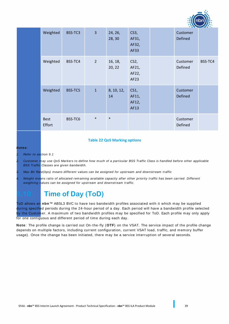
Table 22 QoS Marking options
Notes:
1. Refer to section 9.1
2. Customer may use QoS Markers to define how much of a particular BSS Traffic Class is handled before other applicable BSS Traffic Classes are given bandwidth.
3. Max Bit Rate(bps) means different values can be assigned for upstream and downstream traffic
4. Weight means ratio of allocated remaining available capacity after other priority traffic has been carried. Different weighting values can be assigned for upstream and downstream traffic.
8.10 Time of Day (ToD) ToD allows an nbn™ ABSL3 BVC to have two bandwidth profiles associated with it which may be supplied during specified periods during the 24-hour period of a day. Each period will have a bandwidth profile selected by the Customer. A maximum of two bandwidth profiles may be specified for ToD. Each profile may only apply for one contiguous and different period of time during each day.
Note: The profile change is carried out On-the-fly (OTF) on the VSAT. The service impact of the profile change depends on multiple factors, including current configuration, current VSAT load, traffic, and memory buffer usage). Once the change has been initiated, there may be a service interruption of several seconds.
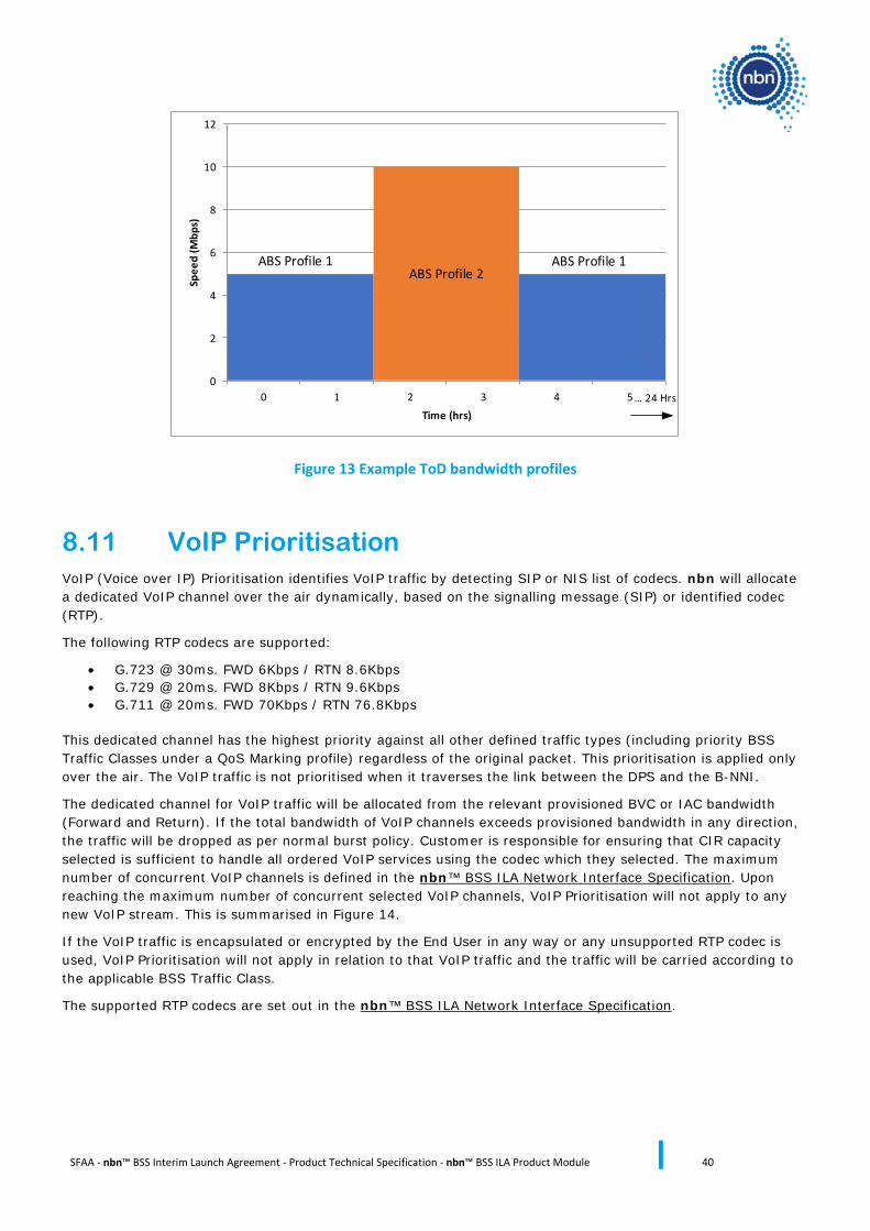
SFAA - nbn™ BSS Interim Launch Agreement - Product Technical Specification - nbn™ BSS ILA Product Module 40
0
2
4
6
8
10
12
0 1 2 3 4 5
Spee
d (M
bps)
Time (hrs)
ABS Profile 2ABS Profile 1 ABS Profile 1
… 24 Hrs
Figure 13 Example ToD bandwidth profiles
8.11 VoIP Prioritisation VoIP (Voice over IP) Prioritisation identifies VoIP traffic by detecting SIP or NIS list of codecs. nbn will allocate a dedicated VoIP channel over the air dynamically, based on the signalling message (SIP) or identified codec (RTP).
The following RTP codecs are supported:
• G.723 @ 30ms. FWD 6Kbps / RTN 8.6Kbps • G.729 @ 20ms. FWD 8Kbps / RTN 9.6Kbps • G.711 @ 20ms. FWD 70Kbps / RTN 76.8Kbps
This dedicated channel has the highest priority against all other defined traffic types (including priority BSS Traffic Classes under a QoS Marking profile) regardless of the original packet. This prioritisation is applied only over the air. The VoIP traffic is not prioritised when it traverses the link between the DPS and the B-NNI.
The dedicated channel for VoIP traffic will be allocated from the relevant provisioned BVC or IAC bandwidth (Forward and Return). If the total bandwidth of VoIP channels exceeds provisioned bandwidth in any direction, the traffic will be dropped as per normal burst policy. Customer is responsible for ensuring that CIR capacity selected is sufficient to handle all ordered VoIP services using the codec which they selected. The maximum number of concurrent VoIP channels is defined in the nbn™ BSS ILA Network Interface Specification. Upon reaching the maximum number of concurrent selected VoIP channels, VoIP Prioritisation will not apply to any new VoIP stream. This is summarised in Figure 14.
If the VoIP traffic is encapsulated or encrypted by the End User in any way or any unsupported RTP codec is used, VoIP Prioritisation will not apply in relation to that VoIP traffic and the traffic will be carried according to the applicable BSS Traffic Class.
The supported RTP codecs are set out in the nbn™ BSS ILA Network Interface Specification.
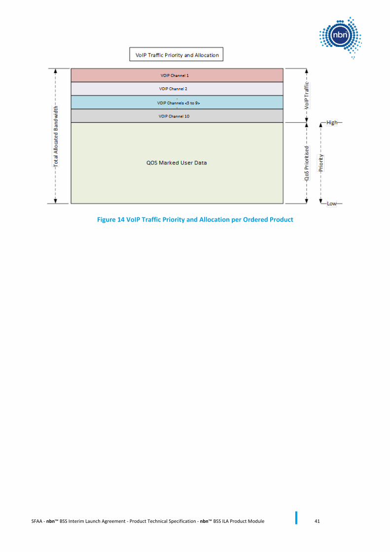
SFAA - nbn™ BSS Interim Launch Agreement - Product Technical Specification - nbn™ BSS ILA Product Module 41
Figure 14 VoIP Traffic Priority and Allocation per Ordered Product
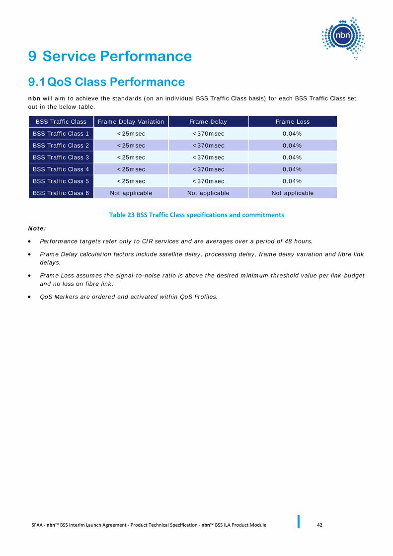
SFAA - nbn™ BSS Interim Launch Agreement - Product Technical Specification - nbn™ BSS ILA Product Module 42
9 Service Performance
9.1 QoS Class Performance nbn will aim to achieve the standards (on an individual BSS Traffic Class basis) for each BSS Traffic Class set out in the below table.
BSS Traffic Class Frame Delay Variation Frame Delay Frame Loss
BSS Traffic Class 1 <25msec <370msec 0.04%
BSS Traffic Class 2 <25msec <370msec 0.04%
BSS Traffic Class 3 <25msec <370msec 0.04%
BSS Traffic Class 4 <25msec <370msec 0.04%
BSS Traffic Class 5 <25msec <370msec 0.04%
BSS Traffic Class 6 Not applicable Not applicable Not applicable
Table 23 BSS Traffic Class specifications and commitments
Note:
• Performance targets refer only to CIR services and are averages over a period of 48 hours.
• Frame Delay calculation factors include satellite delay, processing delay, frame delay variation and fibre link delays.
• Frame Loss assumes the signal-to-noise ratio is above the desired minimum threshold value per link-budget and no loss on fibre link.
• QoS Markers are ordered and activated within QoS Profiles.
SFAA - nbn™ BSS Interim Launch Agreement - Product Technical Specification - nbn™ BSS ILA Product Module 43
10 BSS Class of Service (CoS)
10.1 BSS CoS Architecture The BSS Network supports the carriage of a range of BSS Traffic Classes to accommodate a variety of higher layer applications. Customers may take advantage of these higher layer applications to provide more tailored performance and effective utilisation of the BSS Network.
The BSS Traffic Class of traffic is included in the header information and are set by the Customer in relation to the traffic presented to the BSS Network. The QoS Markers selected by the Customer will define how each BSS Traffic Class is managed within the BSS Network. If the Customer does not select any optional QoS Markers, nbn will manage each BSS Traffic Class presented in the Customer traffic in line with the Default QoS Marker.
10.1.1 Bandwidth Profiles Parameter Considerations
This section describes the bandwidth profile parameters used within the BSS Network.
10.1.1.1 Calculation of Information Rate
All Information Rate limitations, including as set out in this nbn™ BSS ILA Product Technical Specification, are enforced at both the UNI-D and, where applicable, at the nbn™ Upstream Network Boundary between the Customer and the BSS Network.
For clarity, the Information Rate calculation definition is based only upon Layer 2. The effective Layer 2 payload rate of the BSS Network will degrade slightly for lowest-sized Ethernet service frames. This is the expected behaviour for Ethernet-based services for which the bandwidth profile is based on the service frame definitions in the nbn™ BSS ILA Network Interface Specification. It is the responsibility of Customer to accommodate any payload rate degradation as a result of Layer 2 Frame Sizes.
10.1.1.2 Committed Information Rate
Committed Information Rate (CIR) traffic will be carried through the BSS Network in the Forward and Return direction (RF Gateway to the VSAT NTD/ VSAT NTD to the RF Gateway) under normal conditions within performance targets specified in this nbn™ BSS ILA Product Technical Specification.
10.1.1.3 Peak Information Rate
Peak Information Rate (PIR) is the maximum information rate at which the BSS Network is committed to transfer for a particular link under normal conditions. Traffic capacity in excess of the CIR and within the PIR will be carried through the BSS Network without any performance objectives. Traffic that exceeds the PIR will be discarded at ingress to the BSS Network. PIR is subject to the limitations described in sections 4.4, 5.2, 6.2 and 9 of this nbn™ BSS ILA Product Technical Specification and section 25 of the nbn™ BSS ILA Product Description.
10.1.1.4 Network Burst
Network Burst is the capability to transmit traffic higher than the configured bandwidth profile without dropping any packets. Supported Network Burst sizes are set out in the nbn™ BSS ILA Network Interface Specification.