Embed Size (px)
Citation preview
Instruction manual
PROFIBUS DP slave interface for digital multibus
Mass Flow / Pressure / Gateway instruments
Doc. no.: 9.17.025V Date: 12-02-2020
ATTENTION Please read this instruction manual carefully before installing and operating the instrument. Not following the guidelines could result in personal injury and/or damage to the equipment.
BRONKHORST®
Page 2 PROFIBUS DP interface 9.17.025
Disclaimer The information in this manual has been reviewed and is believed to be wholly reliable. No responsibility, however, is assumed for inaccuracies. The material in this manual is for information purposes only.
Copyright All rights reserved. This documentation is protected by copyright. Subject to technical and optical changes as well as printing errors. The information contained in this document is subject to change at any time without prior notification. Bronkhorst High-Tech B.V. reserves the right to modify or improve its products and modify the contents without being obliged to inform any particular persons or organizations. The device specifications and the contents of the package may deviate from what is stated in this document.
Symbols
Important information. Discarding this information could cause injuries to people or damage to the Instrument or installation.
Helpful information. This information will facilitate the use of this instrument.
Additional info available on the internet or from your local sales representative.
Warranty Bronkhorst® products are warranted against defects in material and workmanship for a period of three years from the date of shipment, provided they are used in accordance with the ordering specifications and the instructions in this manual and that they are not subjected to abuse, physical damage or contamination. Products that do not operate properly during this period may be repaired or replaced at no charge. Repairs are normally warranted for one year or the balance of the original warranty, whichever is the longer.
See also paragraph 9 of the Conditions of sales: http://www.bronkhorst.com/files/corporate_headquarters/sales_conditions/en_general_terms_of_sales.pdf
The warranty includes all initial and latent defects, random failures, and undeterminable internal causes. It excludes failures and damage caused by the customer, such as contamination, improper electrical hook-up, physical shock etc. Re-conditioning of products primarily returned for warranty service that is partly or wholly judged non-warranty may be charged for. Bronkhorst High-Tech B.V. or affiliated company prepays outgoing freight charges when any party of the service is performed under warranty, unless otherwise agreed upon beforehand. However, if the product has been returned collect to our factory or service center, these costs are added to the repair invoice. Import and/or export charges, foreign shipping methods/carriers are paid for by the customer.
BRONKHORST®
Page 3 PROFIBUS DP interface 9.17.025
Table of contents
1 GENERAL PRODUCT INFORMATION ................................................................................................. 4 1.1 INTRODUCTION ................................................................................................................................................ 4 1.2 MULTIBUS TYPES .............................................................................................................................................. 4 1.3 REFERENCES TO OTHER APPLICABLE DOCUMENTS ..................................................................................................... 5
1.3.1 Manuals and user guides: ........................................................................................................................... 5 1.3.2 Technical Drawings: .................................................................................................................................... 5 1.3.3 Software tooling: ........................................................................................................................................ 5
1.4 SHORT FORM START-UP ..................................................................................................................................... 6 1.5 OPERATING PRINCIPLES ..................................................................................................................................... 7
2 FIELD BUS INSTALLATION ................................................................................................................. 8 2.1 GENERAL ........................................................................................................................................................ 8 2.2 PROFIBUS DP CONNECTOR .............................................................................................................................. 8 2.3 PROFIBUS DP CABLES ..................................................................................................................................... 9 2.4 MAXIMAL CABLE LENGTH WITH PROFIBUS DP ...................................................................................................... 9 2.5 SPUR LINES WITH PROFIBUS DP .......................................................................................................................10 2.6 NETWORK TERMINATION ..................................................................................................................................11
3 INSTRUMENT CONFIGURATION ..................................................................................................... 12 3.1 INSTRUMENT GSD-FILE ....................................................................................................................................12 3.2 LOAD INSTRUMENT GSD-FILE “BHT_0586.GSD” .................................................................................................13 3.3 ADD AN INSTRUMENT TO PROFIBUS DP .............................................................................................................14 3.4 INSTRUMENT CONFIGURATION SETTINGS ...............................................................................................................15 3.5 INSTRUMENT PARAMETER SETTINGS ....................................................................................................................16
4 GATEWAY CONFIGURATION .......................................................................................................... 17 4.1 GATEWAY GSD-FILE ....................................................................................................................................17 4.2 LOAD GATEWAY GSD-FILE “BHT0F42.GSD” .......................................................................................................18 4.3 ADD GATEWAY TO PROFIBUS DP ................................................................................................................18 4.4 PARAMETER ACCESS THROUGH BRONKHORST® GATEWAY ........................................................................19 4.5 INSTRUMENT PARAMETER SETTINGS OF A FLOW-BUS SYSTEM ...................................................................22
4.5.1 Gateway parameters ................................................................................................................................ 23 5 PROFIBUS SLAVE ADDRESSING ....................................................................................................... 24
5.1 GENERAL .......................................................................................................................................................24 5.2 VIA ROTARY SWITCHES ON THE SIDE OF INSTRUMENT (IF PRESENT) ..............................................................................24 5.3 VIA RS232: FLOWFIX ......................................................................................................................................25 5.4 VIA RS232: OTHER PROGRAMS ..........................................................................................................................26 5.5 VIA MICRO-SWITCH AND LED’S ON TOP OF INSTRUMENT ..........................................................................................26
6 DOWNLOAD TO MASTER ............................................................................................................... 27
7 TEST COMMUNICATION................................................................................................................. 28
8 SAFE STATE ................................................................................................................................... 29
9 TROUBLESHOOTING ...................................................................................................................... 30 9.1 LED INDICATION ..............................................................................................................................................30 9.2 TROUBLESHOOTING HINTS AND TIPS ....................................................................................................................31
10 SERVICE ..................................................................................................................................... 32
11 APPENDIX A: GATEWAY FLOW-BUS NODE ADDRESS SETUP ......................................................... 33
12 APPENDIX B: GATEWAY FLOW-BUS DEBUG EXAMPLE ................................................................. 35
BRONKHORST®
Page 4 PROFIBUS DP interface 9.17.025
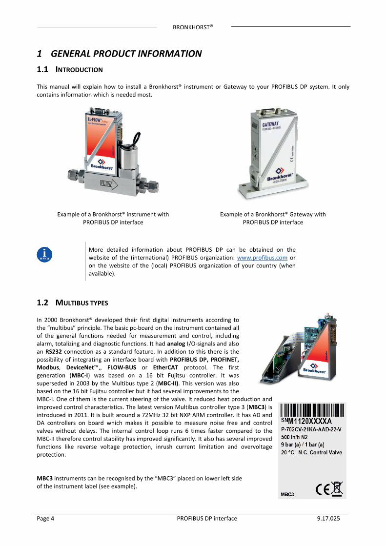
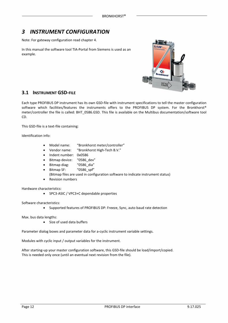
1 GENERAL PRODUCT INFORMATION 1.1 INTRODUCTION This manual will explain how to install a Bronkhorst® instrument or Gateway to your PROFIBUS DP system. It only contains information which is needed most.
Example of a Bronkhorst® instrument with
PROFIBUS DP interface
Example of a Bronkhorst® Gateway with PROFIBUS DP interface
More detailed information about PROFIBUS DP can be obtained on the website of the (international) PROFIBUS organization: www.profibus.com or on the website of the (local) PROFIBUS organization of your country (when available).
1.2 MULTIBUS TYPES In 2000 Bronkhorst® developed their first digital instruments according to the “multibus” principle. The basic pc-board on the instrument contained all of the general functions needed for measurement and control, including alarm, totalizing and diagnostic functions. It had analog I/O-signals and also an RS232 connection as a standard feature. In addition to this there is the possibility of integrating an interface board with PROFIBUS DP, PROFINET, Modbus, DeviceNet™,, FLOW-BUS or EtherCAT protocol. The first generation (MBC-I) was based on a 16 bit Fujitsu controller. It was superseded in 2003 by the Multibus type 2 (MBC-II). This version was also based on the 16 bit Fujitsu controller but it had several improvements to the MBC-I. One of them is the current steering of the valve. It reduced heat production and improved control characteristics. The latest version Multibus controller type 3 (MBC3) is introduced in 2011. It is built around a 72MHz 32 bit NXP ARM controller. It has AD and DA controllers on board which makes it possible to measure noise free and control valves without delays. The internal control loop runs 6 times faster compared to the MBC-II therefore control stability has improved significantly. It also has several improved functions like reverse voltage protection, inrush current limitation and overvoltage protection. MBC3 instruments can be recognised by the “MBC3” placed on lower left side of the instrument label (see example).
BRONKHORST®
Page 5 PROFIBUS DP interface 9.17.025
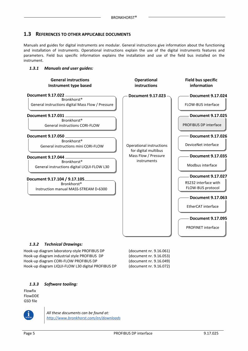
1.3 REFERENCES TO OTHER APPLICABLE DOCUMENTS Manuals and guides for digital instruments are modular. General instructions give information about the functioning and installation of instruments. Operational instructions explain the use of the digital instruments features and parameters. Field bus specific information explains the installation and use of the field bus installed on the instrument.
1.3.1 Manuals and user guides:
1.3.2 Technical Drawings: Hook-up diagram laboratory-style PROFIBUS DP (document nr. 9.16.061) Hook-up diagram industrial style PROFIBUS DP (document nr. 9.16.053) Hook-up diagram CORI-FLOW PROFIBUS DP (document nr. 9.16.049) Hook-up diagram LIQUI-FLOW L30 digital PROFIBUS DP (document nr. 9.16.072)
1.3.3 Software tooling: Flowfix FlowDDE GSD file
All these documents can be found at: http://www.bronkhorst.com/en/downloads
RS232 interface with FLOW-BUS protocol
Modbus interface
DeviceNet interface
PROFIBUS DP interface
FLOW-BUS interface
Operational instructions for digital multibus
Mass Flow / Pressure instruments
Bronkhorst® General instructions digital Mass Flow / Pressure
Bronkhorst® General instructions CORI-FLOW
Bronkhorst® General instructions mini CORI-FLOW
Bronkhorst® General instructions digital LIQUI-FLOW L30
Document 9.17.022
Document 9.17.050
Document 9.17.044
Document 9.17.023 Document 9.17.024
Document 9.17.025
Document 9.17.026
Document 9.17.035
Document 9.17.027
General instructions Instrument type based
Operational instructions
Field bus specific information
Document 9.17.031
Bronkhorst® Instruction manual MASS-STREAM D-6300
EtherCAT interface
Document 9.17.063
PROFINET interface
Document 9.17.095
Document 9.17.104 / 9.17.105
BRONKHORST®
Page 6 PROFIBUS DP interface 9.17.025
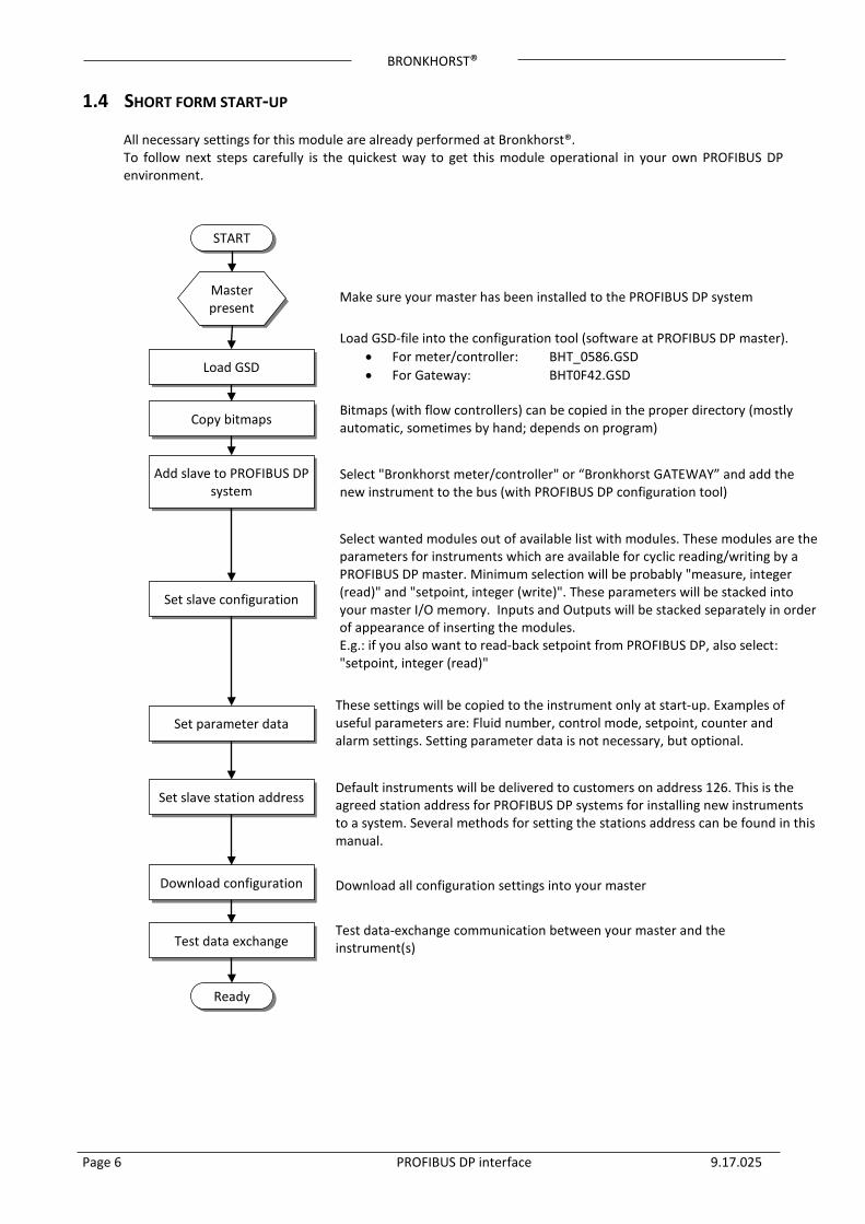
1.4 SHORT FORM START-UP
All necessary settings for this module are already performed at Bronkhorst®. To follow next steps carefully is the quickest way to get this module operational in your own PROFIBUS DP environment.
START
Master present
Load GSD
Make sure your master has been installed to the PROFIBUS DP system
Load GSD-file into the configuration tool (software at PROFIBUS DP master). • For meter/controller: BHT_0586.GSD • For Gateway: BHT0F42.GSD
Copy bitmaps Bitmaps (with flow controllers) can be copied in the proper directory (mostly automatic, sometimes by hand; depends on program)
Add slave to PROFIBUS DP system
Select "Bronkhorst meter/controller" or “Bronkhorst GATEWAY” and add the new instrument to the bus (with PROFIBUS DP configuration tool)
Set slave configuration
Set parameter data These settings will be copied to the instrument only at start-up. Examples of useful parameters are: Fluid number, control mode, setpoint, counter and alarm settings. Setting parameter data is not necessary, but optional.
Set slave station address Default instruments will be delivered to customers on address 126. This is the agreed station address for PROFIBUS DP systems for installing new instruments to a system. Several methods for setting the stations address can be found in this manual.
Download configuration Download all configuration settings into your master
Test data exchange Test data-exchange communication between your master and the instrument(s)
Ready
Select wanted modules out of available list with modules. These modules are the parameters for instruments which are available for cyclic reading/writing by a PROFIBUS DP master. Minimum selection will be probably "measure, integer (read)" and "setpoint, integer (write)". These parameters will be stacked into your master I/O memory. Inputs and Outputs will be stacked separately in order of appearance of inserting the modules. E.g.: if you also want to read-back setpoint from PROFIBUS DP, also select: "setpoint, integer (read)"
BRONKHORST®
Page 7 PROFIBUS DP interface 9.17.025
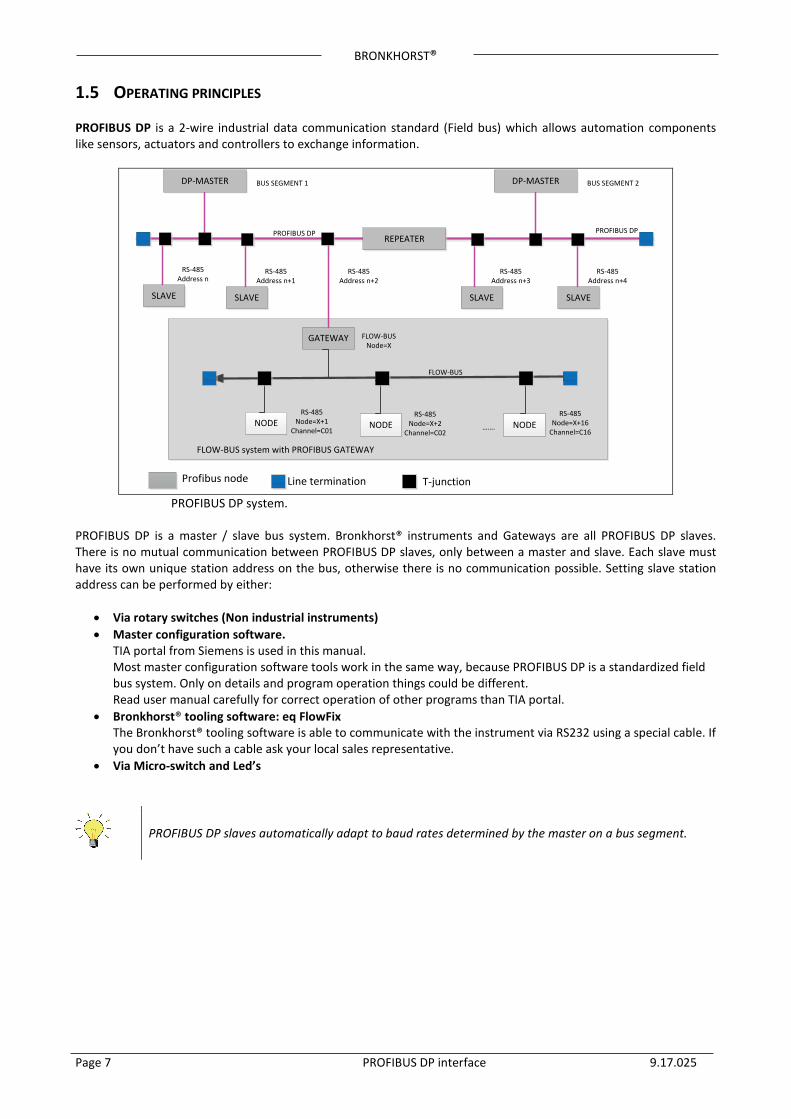
1.5 OPERATING PRINCIPLES PROFIBUS DP is a 2-wire industrial data communication standard (Field bus) which allows automation components like sensors, actuators and controllers to exchange information.
DP-MASTER BUS SEGMENT 1 DP-MASTER BUS SEGMENT 2
SLAVE
RS-485Address n
REPEATER
SLAVE
RS-485Address n+1
GATEWAY
RS-485Address n+2
SLAVE
RS-485Address n+3
SLAVE
RS-485Address n+4
NODERS-485
Node=X+1Channel=C01
NODE NODE…….
FLOW-BUS
PROFIBUS DP PROFIBUS DP
FLOW-BUSNode=X
Profibus node Line termination T-junction
FLOW-BUS system with PROFIBUS GATEWAY
RS-485Node=X+2
Channel=C02
RS-485Node=X+16
Channel=C16
PROFIBUS DP system.
PROFIBUS DP is a master / slave bus system. Bronkhorst® instruments and Gateways are all PROFIBUS DP slaves. There is no mutual communication between PROFIBUS DP slaves, only between a master and slave. Each slave must have its own unique station address on the bus, otherwise there is no communication possible. Setting slave station address can be performed by either:
• Via rotary switches (Non industrial instruments) • Master configuration software. TIA portal from Siemens is used in this manual. Most master configuration software tools work in the same way, because PROFIBUS DP is a standardized field
bus system. Only on details and program operation things could be different. Read user manual carefully for correct operation of other programs than TIA portal. • Bronkhorst® tooling software: eq FlowFix The Bronkhorst® tooling software is able to communicate with the instrument via RS232 using a special cable. If
you don’t have such a cable ask your local sales representative. • Via Micro-switch and Led’s
PROFIBUS DP slaves automatically adapt to baud rates determined by the master on a bus segment.
BRONKHORST®
Page 8 PROFIBUS DP interface 9.17.025
2 FIELD BUS INSTALLATION 2.1 GENERAL
The following installation guidelines only apply to data transfer using copper cables (RS 485) to EN 50170. Furthermore, operators of PROFIBUS equipment are strongly recommended only to use field bus devices and components which have been certified by the PROFIBUS User Organization e.V. (PNO). Certified products have undergone extensive tests carried out by specialists to demonstrate their compliance to the PROFIBUS standard EN 50170 in combination with PROFIBUS devices from other manufacturers. PROFIBUS DP data transfer is based on the RS 485 standard. The relevant features for use with PROFIBUS DP are described in EN 50170.
PROFIBUS DP field bus wiring is the cause of many problems if not proper installed. Please use the instructions below and those mentioned on www.profibus.com
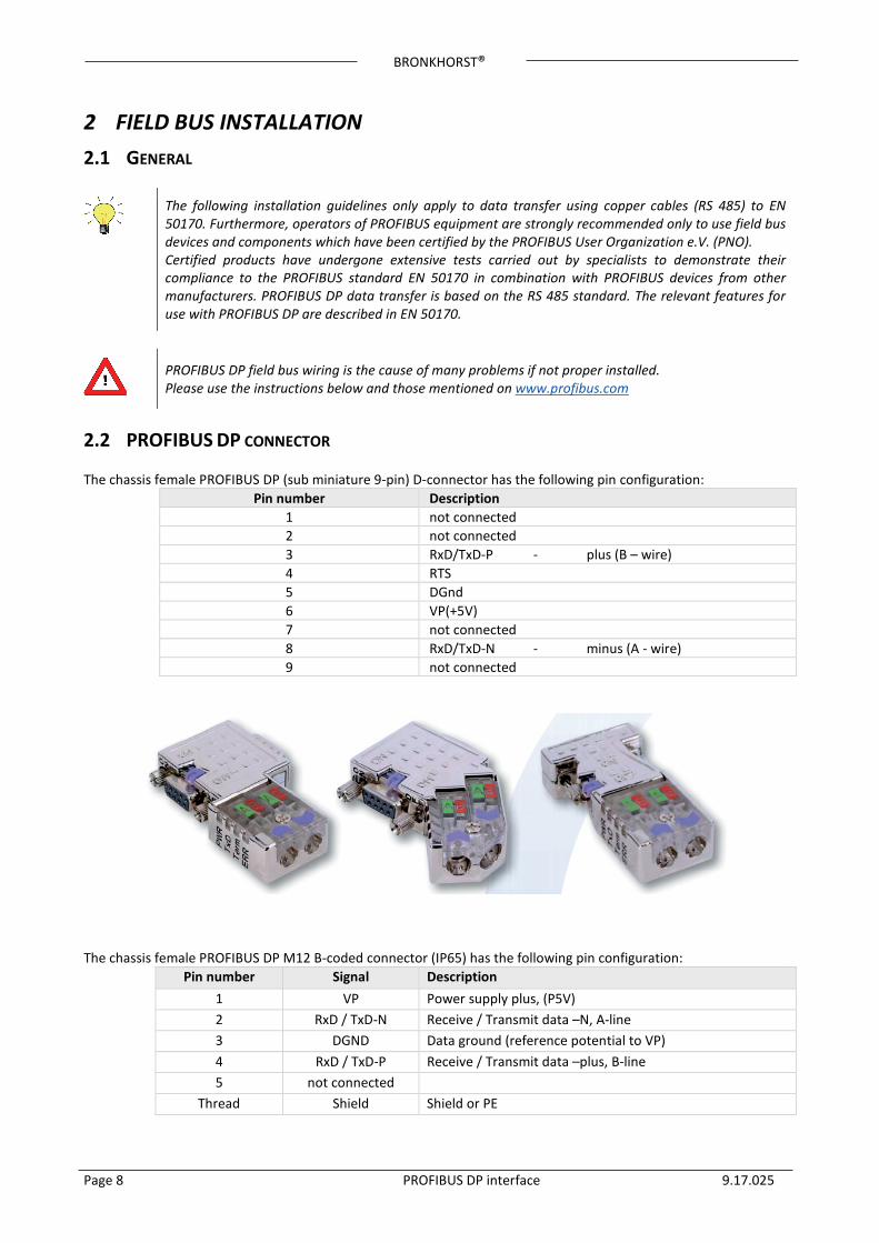
2.2 PROFIBUS DP CONNECTOR The chassis female PROFIBUS DP (sub miniature 9-pin) D-connector has the following pin configuration:
Pin number Description 1 not connected 2 not connected 3 RxD/TxD-P - plus (B – wire) 4 RTS 5 DGnd 6 VP(+5V) 7 not connected 8 RxD/TxD-N - minus (A - wire) 9 not connected
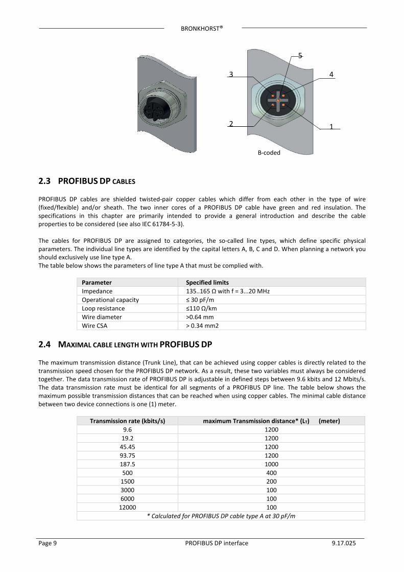
The chassis female PROFIBUS DP M12 B-coded connector (IP65) has the following pin configuration:
Pin number Signal Description 1 VP Power supply plus, (P5V) 2 RxD / TxD-N Receive / Transmit data –N, A-line 3 DGND Data ground (reference potential to VP) 4 RxD / TxD-P Receive / Transmit data –plus, B-line 5 not connected
Thread Shield Shield or PE
BRONKHORST®
Page 9 PROFIBUS DP interface 9.17.025
2.3 PROFIBUS DP CABLES PROFIBUS DP cables are shielded twisted-pair copper cables which differ from each other in the type of wire (fixed/flexible) and/or sheath. The two inner cores of a PROFIBUS DP cable have green and red insulation. The specifications in this chapter are primarily intended to provide a general introduction and describe the cable properties to be considered (see also IEC 61784-5-3). The cables for PROFIBUS DP are assigned to categories, the so-called line types, which define specific physical parameters. The individual line types are identified by the capital letters A, B, C and D. When planning a network you should exclusively use line type A. The table below shows the parameters of line type A that must be complied with.
Parameter Specified limits Impedance 135..165 Ω with f = 3...20 MHz Operational capacity ≤ 30 pF/m Loop resistance ≤110 Ω/km Wire diameter >0.64 mm Wire CSA > 0.34 mm2
2.4 MAXIMAL CABLE LENGTH WITH PROFIBUS DP The maximum transmission distance (Trunk Line), that can be achieved using copper cables is directly related to the transmission speed chosen for the PROFIBUS DP network. As a result, these two variables must always be considered together. The data transmission rate of PROFIBUS DP is adjustable in defined steps between 9.6 kbits and 12 Mbits/s. The data transmission rate must be identical for all segments of a PROFIBUS DP line. The table below shows the maximum possible transmission distances that can be reached when using copper cables. The minimal cable distance between two device connections is one (1) meter.
Transmission rate (kbits/s) maximum Transmission distance* (LT) (meter) 9.6 1200
19.2 1200 45.45 1200 93.75 1200 187.5 1000 500 400
1500 200 3000 100 6000 100
12000 100 * Calculated for PROFIBUS DP cable type A at 30 pF/m
B-coded
4
2
3
5
1
BRONKHORST®
Page 10 PROFIBUS DP interface 9.17.025
2.5 SPUR LINES WITH PROFIBUS DP (Also known as stubs or branches) In table 5 the maximum spur capacitance is set out to the baud rate. With the use of PROFIBUS DP cable type A this will result in the stated length.
Transmission rate
(kbit/s) Total allowable spur capacitance
(nF) Total Spur cable length* (ΣLS)
(m) 19.2 15 500
93.75 3.0 100 187.5 1.0 33 500 0.6 20
1500 0.2 6.7 > 1500 none None
* Calculated for PROFIBUS DP cable type A at 30 pF/m
• The maximal Spur line length is 0.25m • The total Spur line length of a segment represents the sum of all Spurs attached to that segment. • The minimal Trunk line length should be longer than the sum of all Spur lines • Spurs on DP segments should be avoided where possible. • Each PROFIBUS DP device will have a short Spur line carrying the bus signals between the external
bus connector and it’s RS 485 driver chip (for calculations use about 5cm per node). • Devices are tested for reflections as part of the certification process. • Uncertified devices can cause reflections.
Example:
We are installing a M12 system with 19 nodes and a spur length of 25 cm. Additional 30 Sub-D instruments are installed. Transmission rate at 1500 kbits/s. Is this allowed? (19 nodes x 25cm + 19 nodes x 5cm) + 32 nodes x 5cm = 7.3m The maximum spur length at 1500 kbits/s is 6.7m so this is not allowed.
When spur lines are installed, additional termination at the end of a spur-line should not be used! The rule that we must never exceed two terminations per segment, still applies even if using spurs.
References: See document “DP Spur Lines” on http://profibuscentre.com.au/download.html
Spur-lines are not allowed when using higher baud rates (>1.5Mbit/s). At baud rates lower than 1.5Mbit/s, spur-lines are allowed up to the maximum capacitance for the baud rate.
BRONKHORST®
Page 11 PROFIBUS DP interface 9.17.025
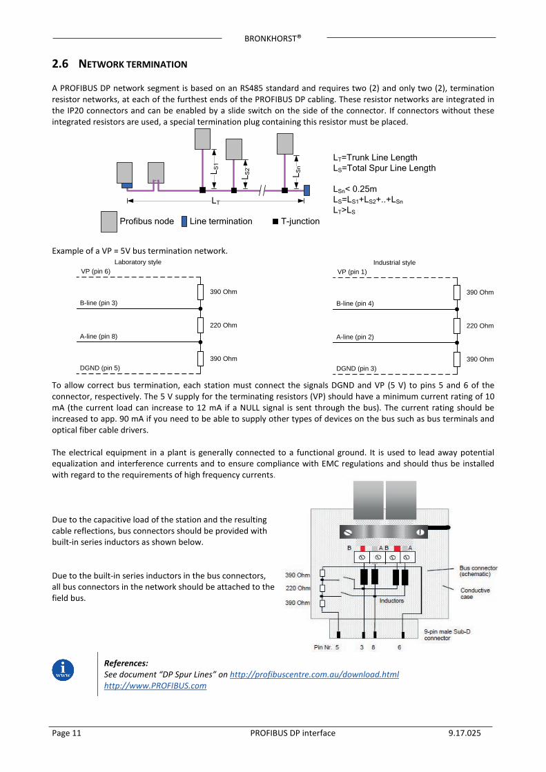
390 Ohm
220 Ohm
390 Ohm
VP (pin 6)
B-line (pin 3)
A-line (pin 8)
DGND (pin 5)
Laboratory style
2.6 NETWORK TERMINATION A PROFIBUS DP network segment is based on an RS485 standard and requires two (2) and only two (2), termination resistor networks, at each of the furthest ends of the PROFIBUS DP cabling. These resistor networks are integrated in the IP20 connectors and can be enabled by a slide switch on the side of the connector. If connectors without these integrated resistors are used, a special termination plug containing this resistor must be placed.
Profibus node Line termination T-junction
LT
L Sn
L S2L S
1
LT=Trunk Line LengthLS=Total Spur Line Length
LSn< 0.25mLS=LS1+LS2+..+LSn
LT>LS
Example of a VP = 5V bus termination network. To allow correct bus termination, each station must connect the signals DGND and VP (5 V) to pins 5 and 6 of the connector, respectively. The 5 V supply for the terminating resistors (VP) should have a minimum current rating of 10 mA (the current load can increase to 12 mA if a NULL signal is sent through the bus). The current rating should be increased to app. 90 mA if you need to be able to supply other types of devices on the bus such as bus terminals and optical fiber cable drivers. The electrical equipment in a plant is generally connected to a functional ground. It is used to lead away potential equalization and interference currents and to ensure compliance with EMC regulations and should thus be installed with regard to the requirements of high frequency currents. Due to the capacitive load of the station and the resulting cable reflections, bus connectors should be provided with built-in series inductors as shown below. Due to the built-in series inductors in the bus connectors, all bus connectors in the network should be attached to the field bus.
References: See document “DP Spur Lines” on http://profibuscentre.com.au/download.html http://www.PROFIBUS.com
390 Ohm
220 Ohm
390 Ohm
VP (pin 1)
B-line (pin 4)
A-line (pin 2)
DGND (pin 3)
Industrial style
BRONKHORST®
Page 12 PROFIBUS DP interface 9.17.025
3 INSTRUMENT CONFIGURATION Note: For gateway configuration read chapter 4. In this manual the software tool TIA-Portal from Siemens is used as an example.
3.1 INSTRUMENT GSD-FILE Each type PROFIBUS DP instrument has its own GSD-file with instrument specifications to tell the master configuration software which facilities/features the instruments offers to the PROFIBUS DP system. For the Bronkhorst® meter/controller the file is called: BHT_0586.GSD. This file is available on the Multibus documentation/software tool CD. This GSD-file is a text-file containing: Identification info:
• Model name: “Bronkhorst meter/controller” • Vendor name: “Bronkhorst High-Tech B.V.” • Indent number: 0x0586 • Bitmap device: “0586_dev” • Bitmap diag: “0586_dia” • Bitmap SF: “0586_spf”
(Bitmap files are used in configuration software to indicate instrument status) • Revision numbers
Hardware characteristics:
• SPC3-ASIC / VPC3+C dependable properties Software characteristics:
• Supported features of PROFIBUS DP: Freeze, Sync, auto baud rate detection
Max. bus data lengths: • Size of used data buffers
Parameter dialog boxes and parameter data for a-cyclic instrument variable settings. Modules with cyclic input / output variables for the instrument. After starting-up your master configuration software, this GSD-file should be load/import/copied. This is needed only once (until an eventual next revision from the file).
BRONKHORST®
Page 13 PROFIBUS DP interface 9.17.025
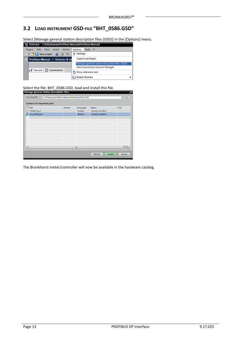
3.2 LOAD INSTRUMENT GSD-FILE “BHT_0586.GSD” Select [Manage general station description files (GSD)] in the [Options] menu.
Select the file: BHT_0586.GSD, load and install this file.
The Bronkhorst meter/controller will now be available in the hardware catalog.
BRONKHORST®
Page 14 PROFIBUS DP interface 9.17.025
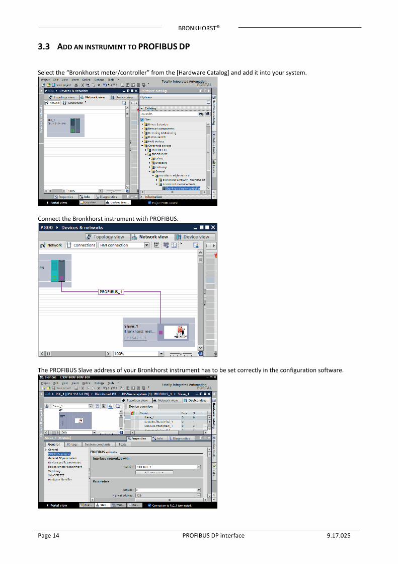
3.3 ADD AN INSTRUMENT TO PROFIBUS DP Select the “Bronkhorst meter/controller” from the [Hardware Catalog] and add it into your system.
Connect the Bronkhorst instrument with PROFIBUS.
The PROFIBUS Slave address of your Bronkhorst instrument has to be set correctly in the configuration software.
BRONKHORST®
Page 15 PROFIBUS DP interface 9.17.025
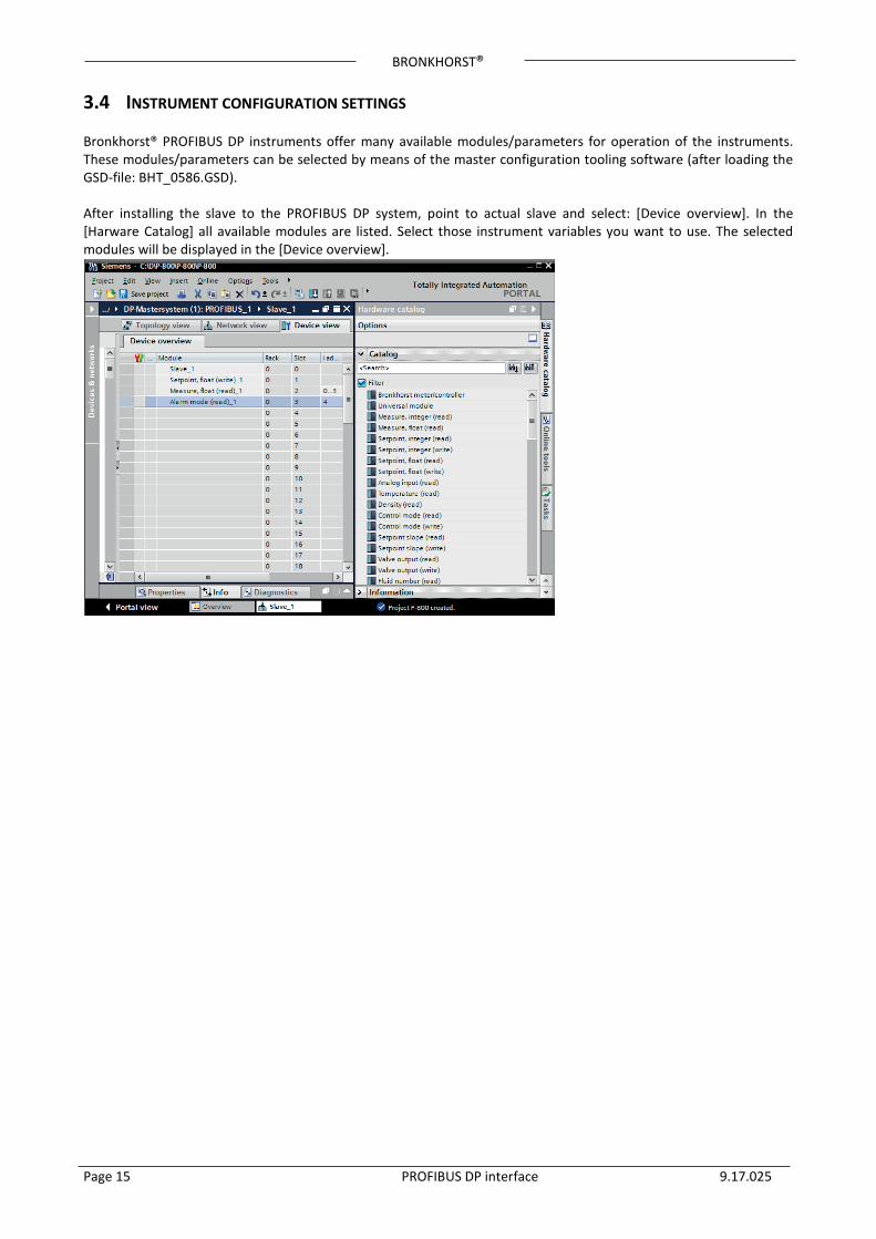
3.4 INSTRUMENT CONFIGURATION SETTINGS Bronkhorst® PROFIBUS DP instruments offer many available modules/parameters for operation of the instruments. These modules/parameters can be selected by means of the master configuration tooling software (after loading the GSD-file: BHT_0586.GSD). After installing the slave to the PROFIBUS DP system, point to actual slave and select: [Device overview]. In the [Harware Catalog] all available modules are listed. Select those instrument variables you want to use. The selected modules will be displayed in the [Device overview].
BRONKHORST®
Page 16 PROFIBUS DP interface 9.17.025
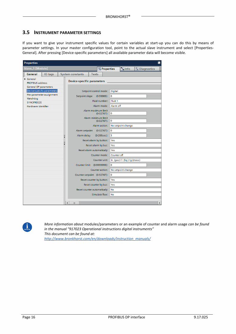
3.5 INSTRUMENT PARAMETER SETTINGS If you want to give your instrument specific values for certain variables at start-up you can do this by means of parameter settings. In your master configuration tool, point to the actual slave instrument and select [Properties-General]. After pressing [Device-specific parameters] all available parameter data will become visible.
More information about modules/parameters or an example of counter and alarm usage can be found in the manual “917023 Operational instructions digital instruments” This document can be found at: http://www.bronkhorst.com/en/downloads/instruction_manuals/
BRONKHORST®
Page 17 PROFIBUS DP interface 9.17.025
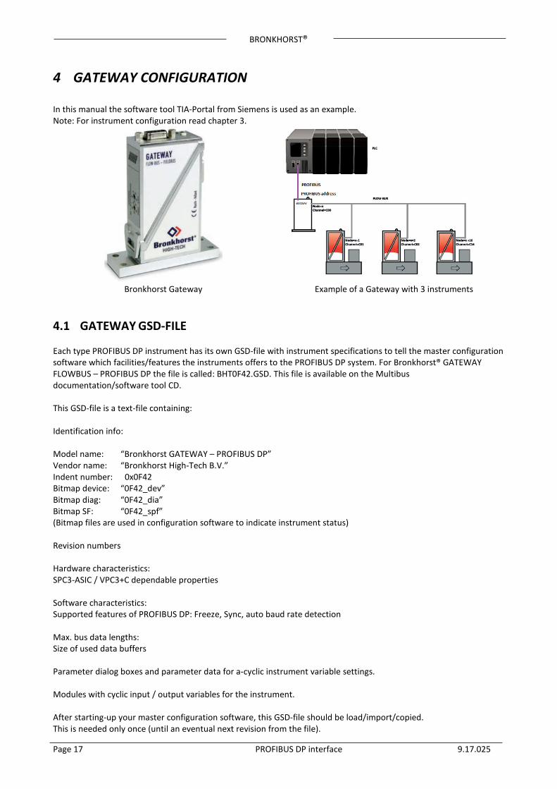
4 GATEWAY CONFIGURATION In this manual the software tool TIA-Portal from Siemens is used as an example. Note: For instrument configuration read chapter 3.
Bronkhorst Gateway Example of a Gateway with 3 instruments
4.1 GATEWAY GSD-FILE Each type PROFIBUS DP instrument has its own GSD-file with instrument specifications to tell the master configuration software which facilities/features the instruments offers to the PROFIBUS DP system. For Bronkhorst® GATEWAY FLOWBUS – PROFIBUS DP the file is called: BHT0F42.GSD. This file is available on the Multibus documentation/software tool CD. This GSD-file is a text-file containing: Identification info: Model name: “Bronkhorst GATEWAY – PROFIBUS DP” Vendor name: “Bronkhorst High-Tech B.V.” Indent number: 0x0F42 Bitmap device: “0F42_dev” Bitmap diag: “0F42_dia” Bitmap SF: “0F42_spf” (Bitmap files are used in configuration software to indicate instrument status) Revision numbers Hardware characteristics: SPC3-ASIC / VPC3+C dependable properties Software characteristics: Supported features of PROFIBUS DP: Freeze, Sync, auto baud rate detection Max. bus data lengths: Size of used data buffers Parameter dialog boxes and parameter data for a-cyclic instrument variable settings. Modules with cyclic input / output variables for the instrument. After starting-up your master configuration software, this GSD-file should be load/import/copied. This is needed only once (until an eventual next revision from the file).
BRONKHORST®
Page 18 PROFIBUS DP interface 9.17.025
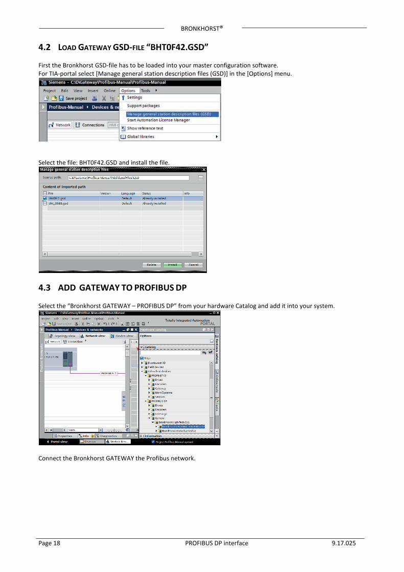
4.2 LOAD GATEWAY GSD-FILE “BHT0F42.GSD” First the Bronkhorst GSD-file has to be loaded into your master configuration software. For TIA-portal select [Manage general station description files (GSD)] in the [Options] menu.
Select the file: BHT0F42.GSD and install the file.
4.3 ADD GATEWAY TO PROFIBUS DP Select the “Bronkhorst GATEWAY – PROFIBUS DP” from your hardware Catalog and add it into your system.
Connect the Bronkhorst GATEWAY the Profibus network.
BRONKHORST®
Page 19 PROFIBUS DP interface 9.17.025
4.4 PARAMETER ACCESS THROUGH BRONKHORST® GATEWAY The Bronkhorst® meter/controllers (nodes) have to be connected to the Gateway through FLOW-BUS. Each device connected to the FLOW-BUS must have its own unique FLOW-BUS node address. The default FLOW-BUS node address of the Gateway is 2. This default must be changed in case of address conflicts (see manual 9.17.022). Such a conflict could for example arise when a E-8000 is connected to the FLOW-BUS (default address of 2). In this case the node address of the GATEWAY has to be changed to a free node address (e.g. node address 3, see appendix A). The PROFIBUS DP master can access the Gateway and the connected FLOW-BUS nodes that are within the FLOW-BUS address range: “Gateway FLOW-BUS address +1” up to “Gateway FLOW-BUS address +16”
Instruments that are outside this range cannot be accessed by the gateway. The PROFIBUS DP master can access the parameters of the Gateway and the connected instruments (within the FLOW-BUS addressing range). The physical FLOW-BUS node address is converted into a channel number:
• C00 (Channel 0): Is the Gateway with FLOW-BUS address X • C01 (Channel 1): Is the instrument with FLOW-BUS address X+1 • C02 (Channel 2): Is the instrument with FLOW-BUS address X+2 • C03 (Channel 3): Is the instrument with FLOW-BUS address X+3 • ….. • C16 (Channel 16): Is the instrument with FLOW-BUS address X+16
Short resume of PROFINET Gateway configurations: Gateway (X00) + X01..X15 – Max 16 adjacent FLOW-BUS nodes. Maximum number of modules = 48 Example: The maximum of 48 modules can be divided over the maximum of 16 FLOW-BUS nodes. The parameters of each instrument can be accessed by adding the Channel number prefix: C<channel number> before the instrument parameter, e.g.:
• “C01 Measure, integer (read)": to access the measurement value of FLOW-BUS Node X+1 • “C02 Measure, integer (read)": to access the measurement value of FLOW-BUS Node X+2
These parameters will be visible after installing the Gateway to the PROFIBUS DP system. Point to actual Gateway and select: [Device overview]. In the [Hardware Catalog] all available modules are listed. Select those instrument parameters you want to use. The selected modules will be displayed in the [Device overview].
BRONKHORST®
Page 20 PROFIBUS DP interface 9.17.025
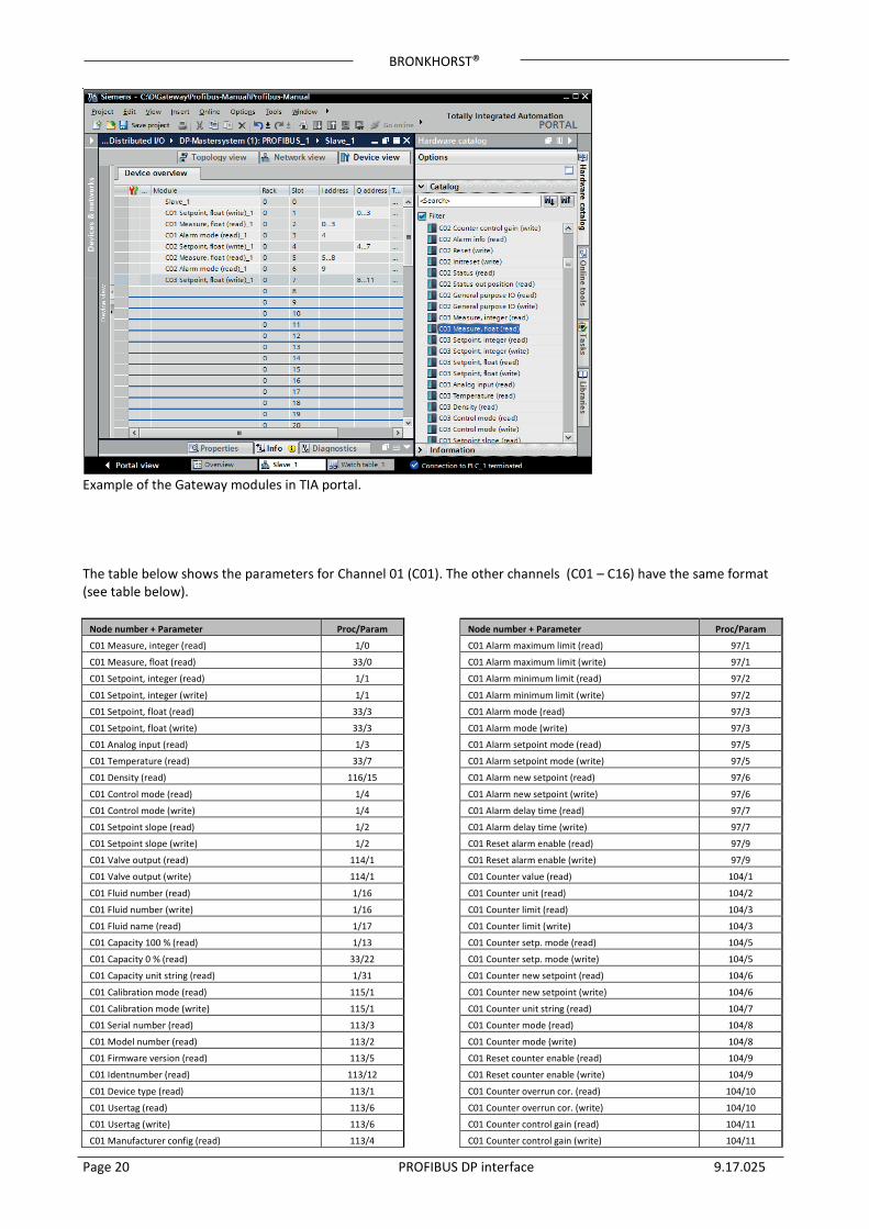
Example of the Gateway modules in TIA portal. The table below shows the parameters for Channel 01 (C01). The other channels (C01 – C16) have the same format (see table below).
Node number + Parameter Proc/Param
C01 Measure, integer (read) 1/0
C01 Measure, float (read) 33/0
C01 Setpoint, integer (read) 1/1
C01 Setpoint, integer (write) 1/1
C01 Setpoint, float (read) 33/3
C01 Setpoint, float (write) 33/3
C01 Analog input (read) 1/3
C01 Temperature (read) 33/7
C01 Density (read) 116/15
C01 Control mode (read) 1/4
C01 Control mode (write) 1/4
C01 Setpoint slope (read) 1/2
C01 Setpoint slope (write) 1/2
C01 Valve output (read) 114/1
C01 Valve output (write) 114/1
C01 Fluid number (read) 1/16
C01 Fluid number (write) 1/16
C01 Fluid name (read) 1/17
C01 Capacity 100 % (read) 1/13
C01 Capacity 0 % (read) 33/22
C01 Capacity unit string (read) 1/31
C01 Calibration mode (read) 115/1
C01 Calibration mode (write) 115/1
C01 Serial number (read) 113/3
C01 Model number (read) 113/2
C01 Firmware version (read) 113/5
C01 Identnumber (read) 113/12
C01 Device type (read) 113/1
C01 Usertag (read) 113/6
C01 Usertag (write) 113/6
C01 Manufacturer config (read) 113/4
Node number + Parameter Proc/Param
C01 Alarm maximum limit (read) 97/1
C01 Alarm maximum limit (write) 97/1
C01 Alarm minimum limit (read) 97/2
C01 Alarm minimum limit (write) 97/2
C01 Alarm mode (read) 97/3
C01 Alarm mode (write) 97/3
C01 Alarm setpoint mode (read) 97/5
C01 Alarm setpoint mode (write) 97/5
C01 Alarm new setpoint (read) 97/6
C01 Alarm new setpoint (write) 97/6
C01 Alarm delay time (read) 97/7
C01 Alarm delay time (write) 97/7
C01 Reset alarm enable (read) 97/9
C01 Reset alarm enable (write) 97/9
C01 Counter value (read) 104/1
C01 Counter unit (read) 104/2
C01 Counter limit (read) 104/3
C01 Counter limit (write) 104/3
C01 Counter setp. mode (read) 104/5
C01 Counter setp. mode (write) 104/5
C01 Counter new setpoint (read) 104/6
C01 Counter new setpoint (write) 104/6
C01 Counter unit string (read) 104/7
C01 Counter mode (read) 104/8
C01 Counter mode (write) 104/8
C01 Reset counter enable (read) 104/9
C01 Reset counter enable (write) 104/9
C01 Counter overrun cor. (read) 104/10
C01 Counter overrun cor. (write) 104/10
C01 Counter control gain (read) 104/11
C01 Counter control gain (write) 104/11

BRONKHORST®
Page 21 PROFIBUS DP interface 9.17.025
Node number + Parameter Proc/Param
C01 Alarm info (read) 1/20
C01 Reset (write) 115/8
C01 Initreset (write) 0/10
C01 Status (read) 115/20
Node number + Parameter Proc/Param
C01 Status out position (read) 115/21
C01 General purpose IO (read) 114/31
C01 General purpose IO (write) 114/31
More information about modules/parameters or an example of counter and alarm usage can be found in the manual “917023 Operational instructions digital instruments”. The description of the parameter can be found in the manual by searching for the process/parameter (Proc/Param), e.g. search for “I/0” to find the definition of “C01 Measure, integer (read)”. This document can be found at: http://www.bronkhorst.com/en/downloads/instruction_manuals/
BRONKHORST®
Page 22 PROFIBUS DP interface 9.17.025
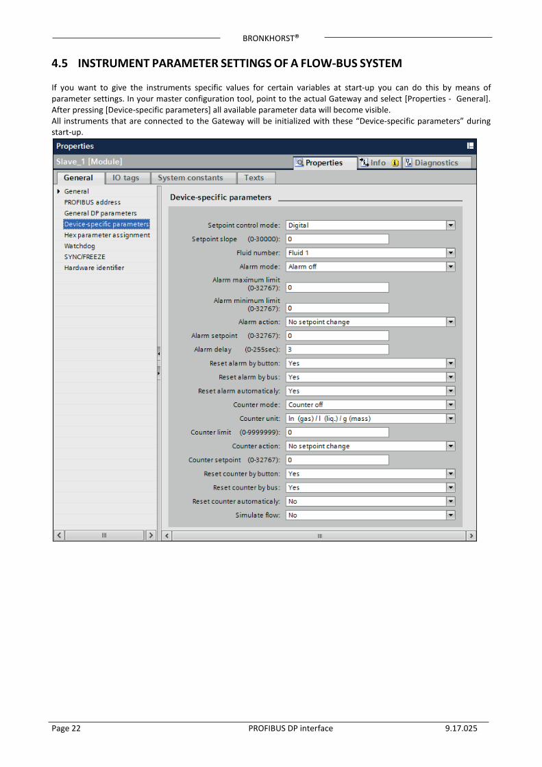
4.5 INSTRUMENT PARAMETER SETTINGS OF A FLOW-BUS SYSTEM If you want to give the instruments specific values for certain variables at start-up you can do this by means of parameter settings. In your master configuration tool, point to the actual Gateway and select [Properties - General]. After pressing [Device-specific parameters] all available parameter data will become visible. All instruments that are connected to the Gateway will be initialized with these “Device-specific parameters” during start-up.
BRONKHORST®
Page 23 PROFIBUS DP interface 9.17.025
4.5.1 Gateway parameters The PROFIBUS DP parameters of the GATEWAY all start with: GATEWAY followed by the parameter, e.g. “GATEWAY Status (read)”. The parameters of the GATEWAY are listed in the table below.
GATEWAY Parameters Description
GATEWAY version (read) Gateway firmware version
GATEWAY FLOWBUS status (read)
16 bit integer which contains flowbus status bits 0 means that flowbus is working correct. Bit 0: when 1: No bus communication. Bit 1: when 1: Communication but no tokens received. Bit 2: when 1: Many communication errors (node occupied?). Bit 15: when 1: Flowbus disabled.
GATEWAY Number of FLOWBUS nodes (read) Represents the number of active flowbus nodes within the gateway node range (3-19).
GATEWAY FLOWBUS live list (read) Array of 16 bytes with nodes active on the corresponding address. 255 means that no node is active on that address.
GATEWAY Safe state (read) Read 0: nodes are in normal operating mode. Read 1: nodes are in safe state
GATEWAY Safe state (write) Write 0: disables safe state Write 1: enable safe state
BRONKHORST®
Page 24 PROFIBUS DP interface 9.17.025
5 PROFIBUS SLAVE ADDRESSING 5.1 GENERAL When you have installed your Bronkhorst® meter/controller / GATEWAY PROFIBUS DP slave and made right settings for slave configuration and parameter data, you can give your instrument the slave address you want. Default instruments will be delivered with slave address 126. This address has been agreed by the PROFIBUS organization to be free for installing new devices to the bus. Changing the station address can be performed in four different ways:
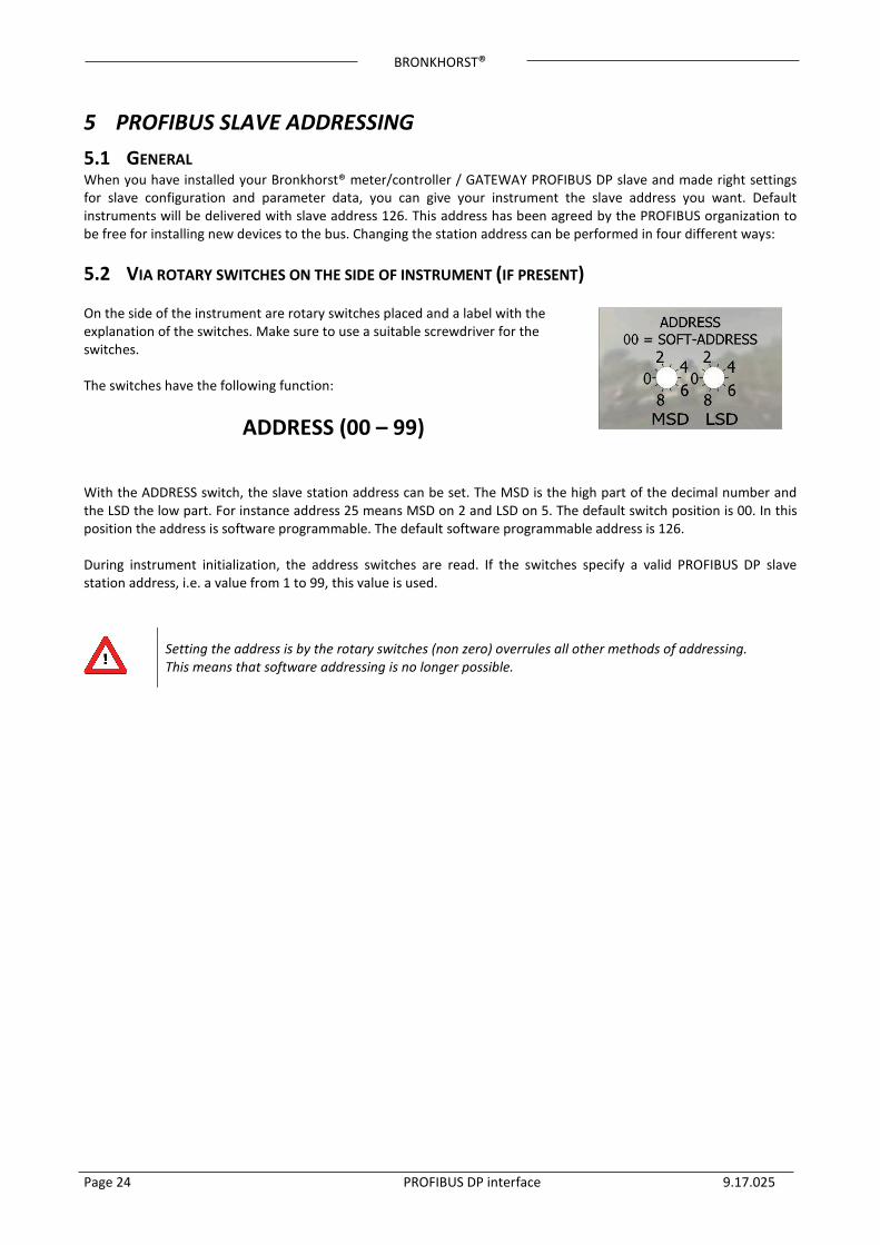
5.2 VIA ROTARY SWITCHES ON THE SIDE OF INSTRUMENT (IF PRESENT) On the side of the instrument are rotary switches placed and a label with the explanation of the switches. Make sure to use a suitable screwdriver for the switches. The switches have the following function:
ADDRESS (00 – 99) With the ADDRESS switch, the slave station address can be set. The MSD is the high part of the decimal number and the LSD the low part. For instance address 25 means MSD on 2 and LSD on 5. The default switch position is 00. In this position the address is software programmable. The default software programmable address is 126. During instrument initialization, the address switches are read. If the switches specify a valid PROFIBUS DP slave station address, i.e. a value from 1 to 99, this value is used.
Setting the address is by the rotary switches (non zero) overrules all other methods of addressing. This means that software addressing is no longer possible.
BRONKHORST®
Page 25 PROFIBUS DP interface 9.17.025
5.3 VIA RS232: FLOWFIX ‘Off-line’ via RS232-service communication port by means of a special tooling program, called FlowFix. FlowFix is a tool for multi-bus instruments which can be used for all field busses enabling the user to:
• Change slave station address • Read and evt. change baud rate (depends on field bus system) • Make a service log file to be send to Bronkhorst® in case of trouble
FlowFix software can be found at the Bronkhorst® website http://www.bronkhorst.com/en/products/accessories/software_tools/
Connect your Bronkhorst® meter/controller PROFIBUS DP slave instrument to a free COM-port using the cable mentioned below.
A special RS232 cable (7.03.366) can be ordered separately. It consists of a T-part with 1 male and 1 female sub-D 9 connector on one instrument-side and a normal female sub-D 9 connector on the side of the computer. By means of this cable it is possible to offer RS232 communication and still be able to connect power-supply and analog interface through the (analog) sub-D 9 connector.
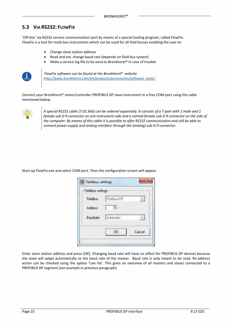
Start-up FlowFix.exe and select COM-port. Then the configuration screen will appear.
Enter slave station address and press [OK]. Changing baud rate will have no effect for PROFIBUS DP devices because the slave will adapt automatically to the baud rate of the master. Baud rate is only meant to be read. Re-address action can be checked using the option ‘Live list’. This gives an overview of all masters and slaves connected to a PROFIBUS DP segment (see example in previous paragraph).
BRONKHORST®
Page 26 PROFIBUS DP interface 9.17.025
5.4 VIA RS232: OTHER PROGRAMS It is also possible to read and or change slave station address or baud rate by means of any program via RS232 using the COM-port of your PC on 38400 Baud. This can be achieved using the FLOW-BUS protocol.
Process Parameter Type R/W Init mode Description 125 9 LONG R/W Soft init Baud rate for field bus interface (PROFIBUS DP: Read only) 125 10 CHR R/W Soft init Field bus station address/MAC ID
Table 6: Address setting and Baud rate reading by RS232 Pro-par
More detailed information about the RS232 protocol (document 9.17.027) can be found at: http://www.bronkhorst.com/en/downloads/instruction_manuals/
5.5 VIA MICRO-SWITCH AND LED’S ON TOP OF INSTRUMENT With the micro-switch on top of the instrument it is possible to change and readout the settings for slave station address and baud rate. The Led’s will indicate the tens of the address with green flashes and the units with red flashes. For baud rate-indication both Led’s will flash (baud rate will adjust to master setting automatically and is therefore read-only).
See document 9.17.023 for a detailed description This document can be found at: http://www.bronkhorst.com/en/downloads/instruction_manuals/
BRONKHORST®
Page 27 PROFIBUS DP interface 9.17.025
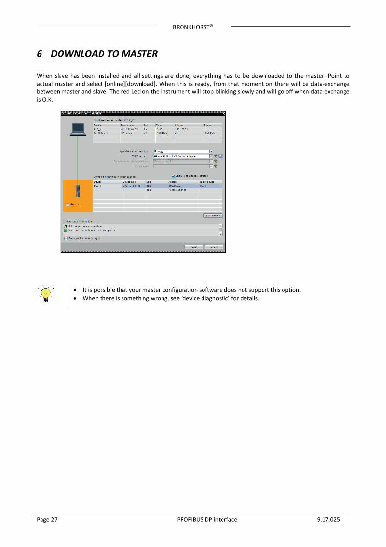
6 DOWNLOAD TO MASTER When slave has been installed and all settings are done, everything has to be downloaded to the master. Point to actual master and select [online][download]. When this is ready, from that moment on there will be data-exchange between master and slave. The red Led on the instrument will stop blinking slowly and will go off when data-exchange is O.K.
• It is possible that your master configuration software does not support this option. • When there is something wrong, see ‘device diagnostic’ for details.
BRONKHORST®
Page 28 PROFIBUS DP interface 9.17.025
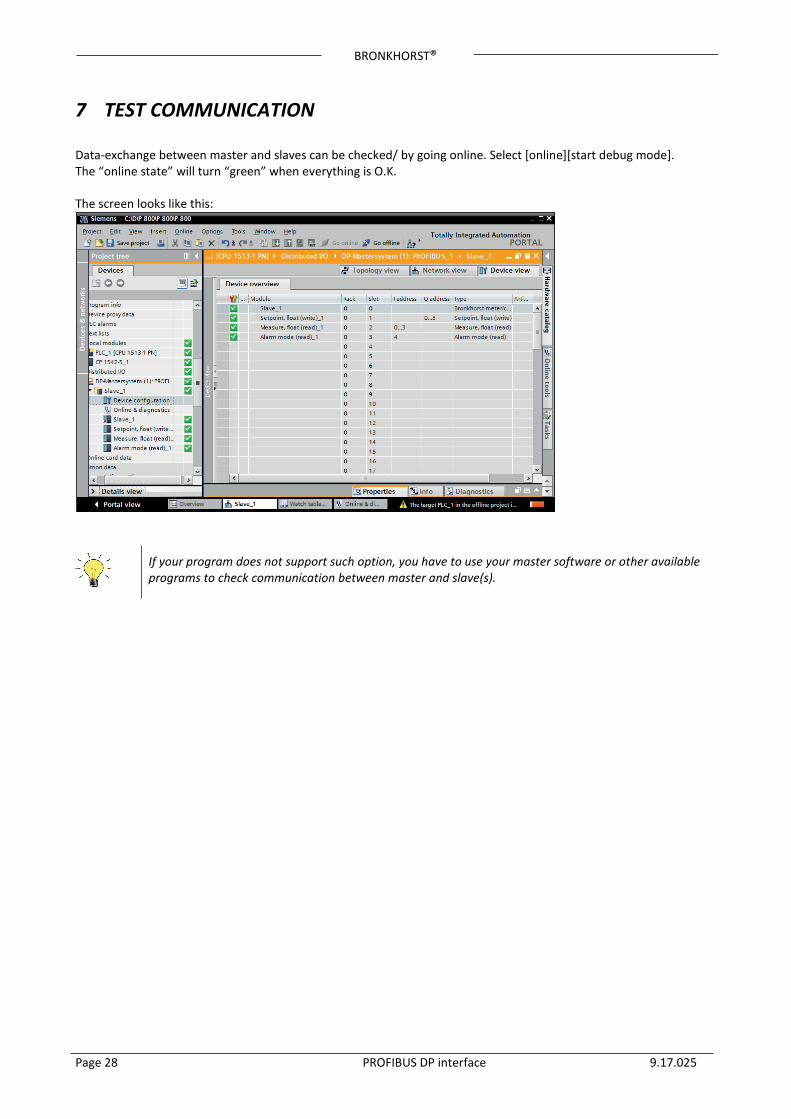
7 TEST COMMUNICATION Data-exchange between master and slaves can be checked/ by going online. Select [online][start debug mode]. The “online state” will turn “green” when everything is O.K. The screen looks like this:
If your program does not support such option, you have to use your master software or other available programs to check communication between master and slave(s).
BRONKHORST®
Page 29 PROFIBUS DP interface 9.17.025
8 SAFE STATE
If PROFIBUS DP communication problems occur, so when instrument is not in data exchange mode, the instrument forces the valve (controllers only) into a safe state mode. This safe state depends on the type of valve. NC valves will be closed, NO valves will be opened fully. The green and red Led on top of the instrument indicates this mode by a short flash: 0.1 sec on, 2 sec off. As long as there is no data exchange between master and slave the instrument will stay in this mode. It will leave this mode automatically when data exchange starts. Via the RS232 communication interface it is possible to force the instrument out of the safe state by changing the control mode to 18 (RS232) or 1 (Analog input). The safe state is also deactivated in the bus configuration mode.
BRONKHORST®
Page 30 PROFIBUS DP interface 9.17.025
9 TROUBLESHOOTING
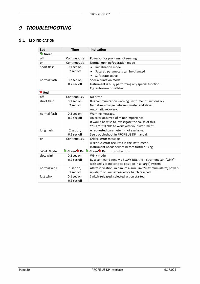
9.1 LED INDICATION
Led Time Indication Green off Continuously Power-off or program not running on Continuously Normal running/operation mode Short flash 0.1 sec on,
2 sec off • Initialization mode • Secured parameters can be changed • Safe state active
normal flash 0.2 sec on, 0.2 sec off
Special function mode Instrument is busy performing any special function. E.g. auto-zero or self-test
Red off Continuously No error short flash 0.1 sec on,
2 sec off Bus communication warning. Instrument functions o.k. No data-exchange between master and slave. Automatic recovery.
normal flash 0.2 sec on, 0.2 sec off
Warning message. An error occurred of minor importance. It would be wise to investigate the cause of this. You are still able to work with your instrument.
long flash 2 sec on, 0.1 sec off
A requested parameter is not available. See troubleshoot in PROFIBUS DP manual.
on Continuously Critical error message. A serious error occurred in the instrument. Instrument needs service before further using.
Wink Mode Green Red Green Red turn by turn slow wink 0.2 sec on,
0.2 sec off Wink mode By a command send via FLOW-BUS the instrument can “wink” with Led’s to indicate its position in a (large) system
normal wink 1 sec on, 1 sec off
Alarm indication: minimum alarm, limit/maximum alarm; power-up alarm or limit exceeded or batch reached.
fast wink 0.1 sec on, 0.1 sec off
Switch-released, selected action started
BRONKHORST®
Page 31 PROFIBUS DP interface 9.17.025
9.2 TROUBLESHOOTING HINTS AND TIPS
PROFIBUS problems No Communication • Check power supply and cabling.
• Check bus termination. At the beginning and end of a bus segment, termination should be enabled in your connector or by means of any external special resistor network.
• Check all PROFIBUS DP settings at your master. Master and slave settings for use of memory modules must be the same. Select at least one module e.g. ‘Measure, integer (read)’ otherwise there will be no data-exchange.
• Check address of interface (slave) • Try to reset the instrument and/or restart your master. • Make sure all settings for your slave are downloaded to your master (otherwise it
won’t work). • Contact PROFIBUS sales representative or service department.
Flow is not reacting to setpoint commands
• In case of PROFIBUS DP communication problems instrument will put it’s valve into a safe state. This will close (NC) or open the valve fully (NO). When data exchange between master and slave has been re-established, instrument will respond to setpoint again. For overruling safe state via RS232 interface, see setpoint /control modes in chapter 2.5 from doc. nr. 9.17.023, (digital instrument description).
Red Led has long flash • Make sure the requested parameters are available in the particular Bronkhorst®
PROFIBUS DP slave. • Delete the PROFIBUS DP slave configuration and add a new slave in your software,
this will remove a corruption in the software configuration.
GATEWAY problems FLOW-BUS problems No Comunication * Check power supply and cabling.
* Check all FLOW-BUS settings of the GATEWAY and attached instruments (see Appendix A: GATEWAY FLOW-BUS node address setup).
* Check the if there are no FLOW-BUS address node conflicts: All attached instruments must have an unique node address. The Gateway can only communicate with instruments with node address: “Gateway FLOW-BUS address +1” up to “Gateway FLOW-BUS address +16”
* Try to reset the instrument and/or restart your GATEWAY. * Use the following GATEWAY parameters to debug your FLOW-BUS communication:
* GATEWAY number of nodes (read) * GATEWAY FLOWBUS live list (read) * GATEWAY FLOWBUS status (read) * See example in Appendix B

BRONKHORST®
Page 32 PROFIBUS DP interface 9.17.025
10 SERVICE For current information on Bronkhorst® and service addresses please visit our website:
http://www.bronkhorst.com
Do you have any questions about our products? Our Sales Department will gladly assist you selecting the right product for your application. Contact sales by e-mail:
For after-sales questions, our Customer Service Department is available with help and guidance. To contact CSD by e-mail:
No matter the time zone, our experts within the Support Group are available to answer your request immediately or ensure appropriate further action. Our experts can be reached at:
+31 859 02 18 66
BRONKHORST®
Page 33 PROFIBUS DP interface 9.17.025
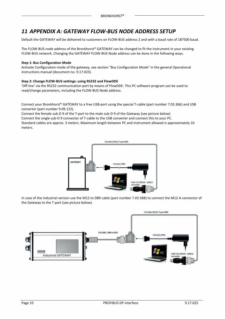
11 APPENDIX A: GATEWAY FLOW-BUS NODE ADDRESS SETUP Default the GATEWAY will be delivered to customers on FLOW-BUS address 2 and with a baud rate of 187500 baud. The FLOW-BUS node address of the Bronkhorst® GATEWAY can be changed to fit the instrument in your existing FLOW-BUS network. Changing the GATEWAY FLOW-BUS Node address can be done in the following ways. Step 1: Bus Configuration Mode Activate Configuration mode of the gateway, see section "Bus Configuration Mode" in the general Operational instructions manual (document no. 9.17.023). Step 2: Change FLOW-BUS settings: using RS232 and FlowDDE ‘Off-line’ via the RS232 communication port by means of FlowDDE. This PC software program can be used to read/change parameters, including the FLOW-BUS Node address. Connect your Bronkhorst® GATEWAY to a free USB-port using the special T-cable (part number 7.03.366) and USB converter (part number 9.09.122). Connect the female sub-D 9 of the T-part to the male sub-D 9 of the Gateway (see picture below) Connect the single sub-D 9 connector of T-cable to the USB converter and connect this to your PC. Standard cables are approx. 3 meters. Maximum length between PC and instrument allowed is approximately 10 meters.
In case of the industrial version use the M12 to DB9 cable (part number 7.03.588) to connect the M12-A connector of the Gateway to the T-part (see picture below).
Industrial GATEWAY
BRONKHORST®
Page 34 PROFIBUS DP interface 9.17.025
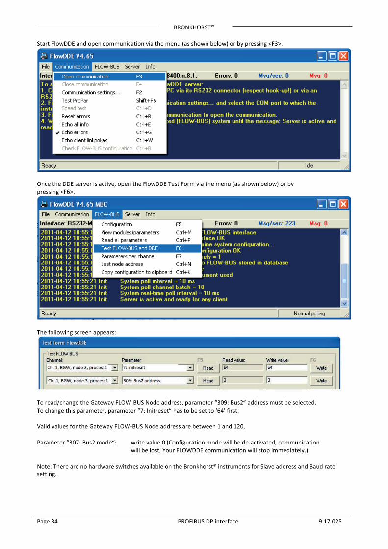
Start FlowDDE and open communication via the menu (as shown below) or by pressing <F3>.
Once the DDE server is active, open the FlowDDE Test Form via the menu (as shown below) or by pressing <F6>.
The following screen appears:
To read/change the Gateway FLOW-BUS Node address, parameter “309: Bus2” address must be selected. To change this parameter, parameter “7: Initreset” has to be set to ‘64’ first. Valid values for the Gateway FLOW-BUS Node address are between 1 and 120, Parameter “307: Bus2 mode“: write value 0 (Configuration mode will be de-activated, communication
will be lost, Your FLOWDDE communication will stop immediately.)
Note: There are no hardware switches available on the Bronkhorst® instruments for Slave address and Baud rate setting.
BRONKHORST®
Page 35 PROFIBUS DP interface 9.17.025
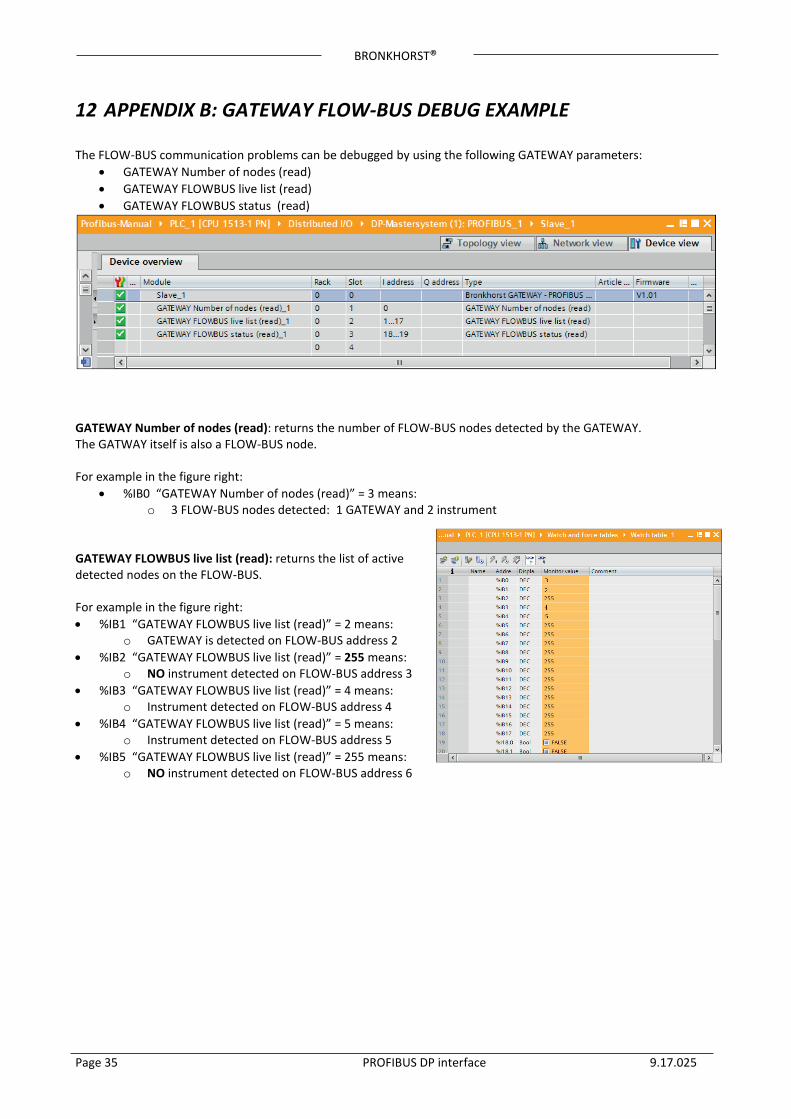
12 APPENDIX B: GATEWAY FLOW-BUS DEBUG EXAMPLE The FLOW-BUS communication problems can be debugged by using the following GATEWAY parameters:
• GATEWAY Number of nodes (read) • GATEWAY FLOWBUS live list (read) • GATEWAY FLOWBUS status (read)
GATEWAY Number of nodes (read): returns the number of FLOW-BUS nodes detected by the GATEWAY. The GATWAY itself is also a FLOW-BUS node. For example in the figure right:
• %IB0 “GATEWAY Number of nodes (read)” = 3 means: o 3 FLOW-BUS nodes detected: 1 GATEWAY and 2 instrument
GATEWAY FLOWBUS live list (read): returns the list of active detected nodes on the FLOW-BUS. For example in the figure right: • %IB1 “GATEWAY FLOWBUS live list (read)” = 2 means:
o GATEWAY is detected on FLOW-BUS address 2 • %IB2 “GATEWAY FLOWBUS live list (read)” = 255 means:
o NO instrument detected on FLOW-BUS address 3 • %IB3 “GATEWAY FLOWBUS live list (read)” = 4 means:
o Instrument detected on FLOW-BUS address 4 • %IB4 “GATEWAY FLOWBUS live list (read)” = 5 means:
o Instrument detected on FLOW-BUS address 5 • %IB5 “GATEWAY FLOWBUS live list (read)” = 255 means:
o NO instrument detected on FLOW-BUS address 6
BRONKHORST®
Page 36 PROFIBUS DP interface 9.17.025
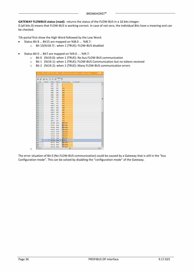
GATEWAY FLOWBUS status (read): returns the status of the FLOW-BUS in a 16 bits integer. 0 (all bits 0) means that FLOW-BUS is working correct. In case of not zero, the individual Bits have a meaning and can be checked. TIA-portal first show the High Word followed by the Low Word: • Status Bit 8 … Bit15 are mapped on %I8.0 ... %I8.7:
o Bit 15(%I18.7) : when 1 (TRUE): FLOW-BUS disabled
• Status Bit 0 … Bit7 are mapped on %I9.0 .. . %I9.7: o Bit 0 (%I19.0): when 1 (TRUE): No bus FLOW-BUS communication o Bit 1 (%I19.1): when 1 (TRUE): FLOW-BUS Communication but no tokens received o Bit 2 (%I19.2): when 1 (TRUE): Many FLOW-BUS communication errors
o The error situation of Bit 0 (No FLOW-BUS communication) could be caused by a Gateway that is still in the “bus Configuration mode”. This can be solved by disabling the “configuration mode” of the Gateway.


![BU 2700 PROFIBUS DP Busschnittstelle - NORD€¦ · Sicherheit/PROFIBUS DP [BU 2700]/Bestimmungsgemäße Ver wendung PROFIBUS DP @ 8\mod_1461835577600_6.docx @ 2249428 @ 2 @ 1 2.1](https://img.pdfslide.net/doc/110x75/5eab6d581394d0309b74d9e9/bu-2700-profibus-dp-busschnittstelle-nord-sicherheitprofibus-dp-bu-2700bestimmungsgeme.jpg)