Embed Size (px)
Citation preview
1
Programmable Controller CQM1H
The CQM1H’s rack-less modular design letsyou customize your control system by adding“inner boards” for advanced functions, as wellas specialized I/O and communicationsmodules. CQM1H offers the most flexibility ofall PLC systems in its class.
4 different base CPUs to choose from; 16DC inputs built in; expands up to 512 points
No separate backplane required
Inner Boards allow “customized”configuration of the CPU
Serial communications inner board supportsprotocol macro feature for communicationwith third-party serial devices
Supports all existing and new CQM1 I/Oand specialized I/O modules
Optional memory cassettes allow backup ofsensitive data, provides a real-time clock
ControllerLink network transmits 8 kworddata packets at up to 2 Mbps; 32 nodes
Advanced instruction set includes PID,floating point math, protocol macroinstructions and more
CompoBus/S, SYSMAC BUS andAS-interface masters support remote I/O
Up to 15.2 kwords of program memory
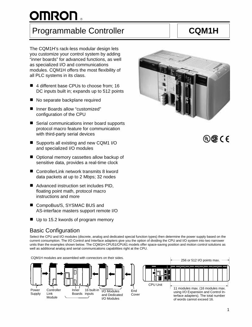
Basic ConfigurationSelect the CPU and I/O modules (discrete, analog and dedicated special function types) then determine the power supply based on thecurrent consumption. The I/O Control and Interface adapters give you the option of dividing the CPU and I/O system into two narrowerunits than the examples shown below. The CQM1H-CPU51/CPU61 models offer space-saving position and motion control solutions aswell as additional analog and serial communications capabilities right at the CPU.
ControllerLink Module
Inner Boards
I/O Modulesand DedicatedI/O Modules
256 or 512 I/O points max.
11 modules max. (16 modules max.using I/O Expansion and Control In-terface adapters). The total numberof words cannot exceed 16.
CQM1H modules are assembled with connectors on their sides.
Power Supply
16 built-ininputs
CPU Unit
End Cover
CQM1HCQM1H
2
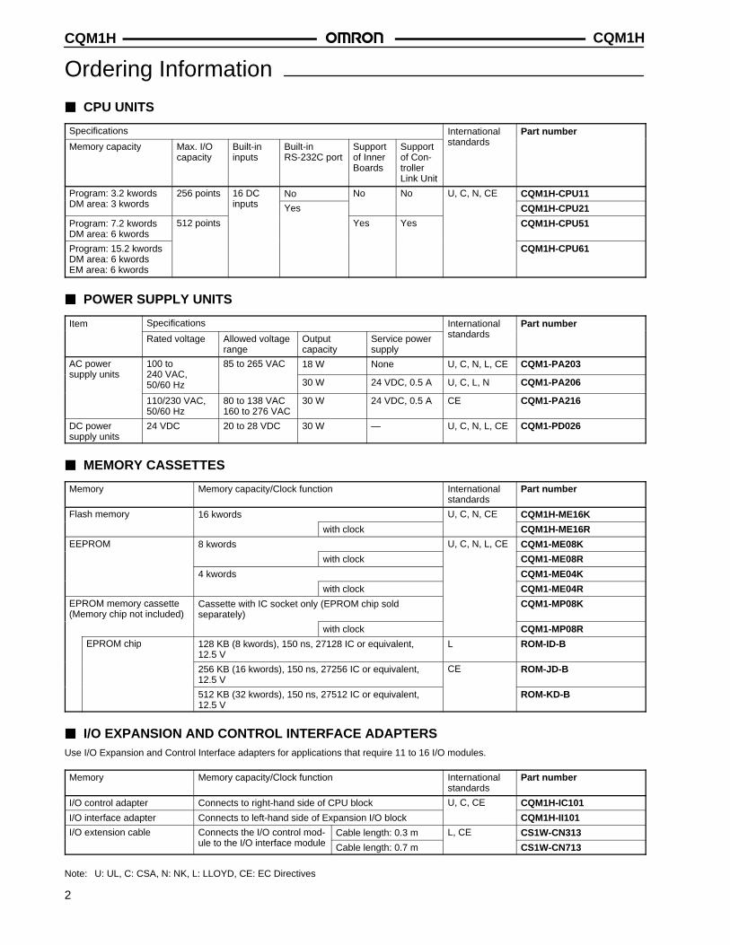
Ordering Information
CPU UNITS
Specifications International Part number
Memory capacity Max. I/O capacity
Built-in inputs
Built-inRS-232C port
Supportof InnerBoards
Supportof Con-trollerLink Unit
standards
Program: 3.2 kwords 256 points 16 DC No No No U, C, N, CE CQM1H-CPU11DM area: 3 kwords inputs Yes CQM1H-CPU21
Program: 7.2 kwordsDM area: 6 kwords
512 points Yes Yes CQM1H-CPU51
Program: 15.2 kwordsDM area: 6 kwordsEM area: 6 kwords
CQM1H-CPU61
POWER SUPPLY UNITS
Item Specifications International Part number
Rated voltage Allowed voltagerange
Output capacity
Service powersupply
standards
AC power 100 to 85 to 265 VAC 18 W None U, C, N, L, CE CQM1-PA203supply units 240 VAC,
50/60 Hz 30 W 24 VDC, 0.5 A U, C, L, N CQM1-PA206
110/230 VAC,50/60 Hz
80 to 138 VAC160 to 276 VAC
30 W 24 VDC, 0.5 A CE CQM1-PA216
DC power supply units
24 VDC 20 to 28 VDC 30 W — U, C, N, L, CE CQM1-PD026
MEMORY CASSETTES
Memory Memory capacity/Clock function Internationalstandards
Part number
Flash memory 16 kwords U, C, N, CE CQM1H-ME16K
with clock CQM1H-ME16R
EEPROM 8 kwords U, C, N, L, CE CQM1-ME08K
with clock CQM1-ME08R
4 kwords CQM1-ME04K
with clock CQM1-ME04R
EPROM memory cassette(Memory chip not included)
Cassette with IC socket only (EPROM chip sold separately)
CQM1-MP08K
with clock CQM1-MP08R
EPROM chip 128 KB (8 kwords), 150 ns, 27128 IC or equivalent, 12.5 V
L ROM-ID-B
256 KB (16 kwords), 150 ns, 27256 IC or equivalent,12.5 V
CE ROM-JD-B
512 KB (32 kwords), 150 ns, 27512 IC or equivalent,12.5 V
ROM-KD-B
I/O EXPANSION AND CONTROL INTERFACE ADAPTERSUse I/O Expansion and Control Interface adapters for applications that require 11 to 16 I/O modules.
Memory Memory capacity/Clock function Internationalstandards
Part number
I/O control adapter Connects to right-hand side of CPU block U, C, CE CQM1H-IC101
I/O interface adapter Connects to left-hand side of Expansion I/O block CQM1H-II101
I/O extension cable Connects the I/O control mod- Cable length: 0.3 m L, CE CS1W-CN313ule to the I/O interface module Cable length: 0.7 m CS1W-CN713
Note: U: UL, C: CSA, N: NK, L: LLOYD, CE: EC Directives
CQM1H CQM1H
3
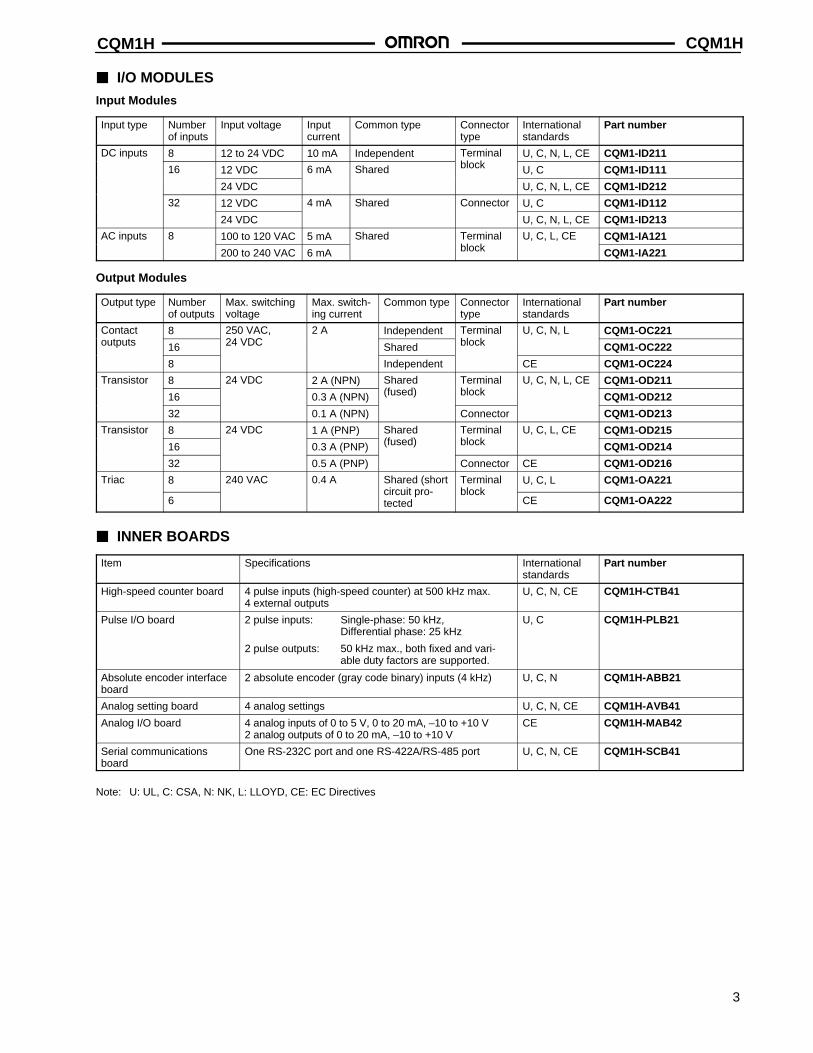
I/O MODULES
Input Modules
Input type Numberof inputs
Input voltage Inputcurrent
Common type Connectortype
Internationalstandards
Part number
DC inputs 8 12 to 24 VDC 10 mA Independent Terminal U, C, N, L, CE CQM1-ID211
16 12 VDC 6 mA Shared block U, C CQM1-ID111
24 VDC U, C, N, L, CE CQM1-ID212
32 12 VDC 4 mA Shared Connector U, C CQM1-ID112
24 VDC U, C, N, L, CE CQM1-ID213
AC inputs 8 100 to 120 VAC 5 mA Shared Terminal U, C, L, CE CQM1-IA121
200 to 240 VAC 6 mA block CQM1-IA221
Output Modules
Output type Numberof outputs
Max. switchingvoltage
Max. switch-ing current
Common type Connectortype
Internationalstandards
Part number
Contact 8 250 VAC, 2 A Independent Terminal U, C, N, L CQM1-OC221outputs 16 24 VDC Shared block CQM1-OC222
8 Independent CE CQM1-OC224
Transistor 8 24 VDC 2 A (NPN) Shared Terminal U, C, N, L, CE CQM1-OD211
16 0.3 A (NPN) (fused) block CQM1-OD212
32 0.1 A (NPN) Connector CQM1-OD213
Transistor 8 24 VDC 1 A (PNP) Shared Terminal U, C, L, CE CQM1-OD215
16 0.3 A (PNP) (fused) block CQM1-OD214
32 0.5 A (PNP) Connector CE CQM1-OD216
Triac 8 240 VAC 0.4 A Shared (short Terminal U, C, L CQM1-OA221
6circuit pro-tected
blockCE CQM1-OA222
INNER BOARDS
Item Specifications Internationalstandards
Part number
High-speed counter board 4 pulse inputs (high-speed counter) at 500 kHz max.4 external outputs
U, C, N, CE CQM1H-CTB41
Pulse I/O board 2 pulse inputs: Single-phase: 50 kHz, Differential phase: 25 kHz
2 pulse outputs: 50 kHz max., both fixed and vari-able duty factors are supported.
U, C CQM1H-PLB21
Absolute encoder interfaceboard
2 absolute encoder (gray code binary) inputs (4 kHz) U, C, N CQM1H-ABB21
Analog setting board 4 analog settings U, C, N, CE CQM1H-AVB41
Analog I/O board 4 analog inputs of 0 to 5 V, 0 to 20 mA, –10 to +10 V2 analog outputs of 0 to 20 mA, –10 to +10 V
CE CQM1H-MAB42
Serial communicationsboard
One RS-232C port and one RS-422A/RS-485 port U, C, N, CE CQM1H-SCB41
Note: U: UL, C: CSA, N: NK, L: LLOYD, CE: EC Directives
CQM1HCQM1H
4
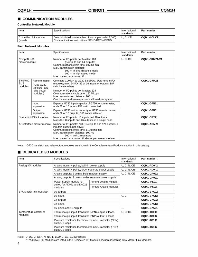
COMMUNICATION MODULES
Controller Network Module
Item Specifications Internationalstandards
Part number
Controller Link module(wired)
Data link (Maximum number of words per node: 8,000)Communications instructions: SEND/RECV/CMND
U, C, CE CQM1H-CLK21
Field Network Modules
Item Specifications Internationalstandards
Part number
CompoBus/S master module
Number of I/O points per Master: 128 (64 inputs and 64 outputs; )
Communications cycle time: 0.5 ms min.Max. transmission distance:
500 m in long-distance mode100 m in high-speed mode
Max. slaves per master: 32
U, C, CE CQM1-SRM21-V1
SYSMACBUS modules
Remote master
(*Use G730transistor andrelay outputmodules.)
Connects CQM1H to G730 SYSMAC BUS remote I/Omodules; max. 64 I/O (32 or 16 inputs or outputs, DIPswitch selectable)
Number of I/O points per Master: 128Communications cycle time: 187.5 kbpsMax. transmission distance: 200 mOne master and two expansions allowed per system
CQM1-G7M21
Input expansion
Expands G730 input capacity of G730 remote master;adds 32 or 16 inputs, DIP switch selected
CQM1-G7N11
Output expansion
Expands G730 output capacity of G730 remote master;adds 32 or 16 outputs, DIP switch selected
CQM1-G7N01
DeviceNet I/O link module Number of I/O points: 16 inputs and 16 outputsMaps the 16 inputs and 16 outputs as a single node.
CQM1-DRT21
AS-interface master module Number of I/O points: 248 (124 inputs and 124 outputs; 4inputs/4 outputs per slave)Communications cycle time: 5.148 ms min.Max. transmission distance: 100 m;
300 m with 2 repeatersMax. slaves per master: 31 slaves per master module
CQM1-ARM21
Note: *G730 transistor and relay output modules are shown in the Complementary Products section in this catalog.
DEDICATED I/O MODULES
Item Specifications Internationalstandards
Part number
Analog I/O modules Analog inputs: 4 points, built-in power supply U, C, N, CE CQM1-AD042
Analog inputs: 4 points, order separate power supply U, C, N, CE CQM1-AD041
Analog outputs: 2 points, built-in power supply U, C, N, CE CQM1-DA022Analog outputs: 2 points, order separate power supply CQM1-DA021
Power Supply Module re- For one Analog module CQM1-IPS01quired for AD041 and DA021modules For two Analog modules CQM1-IPS02
B7A Master link modules* 16 outputs — CQM1-B7A02
16 inputs U, C CQM1-B7A12
32 outputs CQM1-B7A03
32 inputs CQM1-B7A13
16 inputs and 16 outputs — CQM1-B7A21
Temperature controller Thermocouple input, transistor (NPN) output, 2 loops U, C, CE CQM1-TC001modules Thermocouple input, transistor (PNP) output, 2 loops CQM1-TC002
Platinum resistance thermometer input, transistor (NPN)output, 2 loops
CQM1-TC101
Platinum resistance thermometer input, transistor (PNP)output, 2 loops
CQM1-TC102
Note: U: UL, C: CSA, N: NK, L: LLOYD, CE: EC Directives*B7A Slave Link Modules are listed in the Dedicated I/O Modules section describing B7A Master Link Modules.
CQM1H CQM1H
5
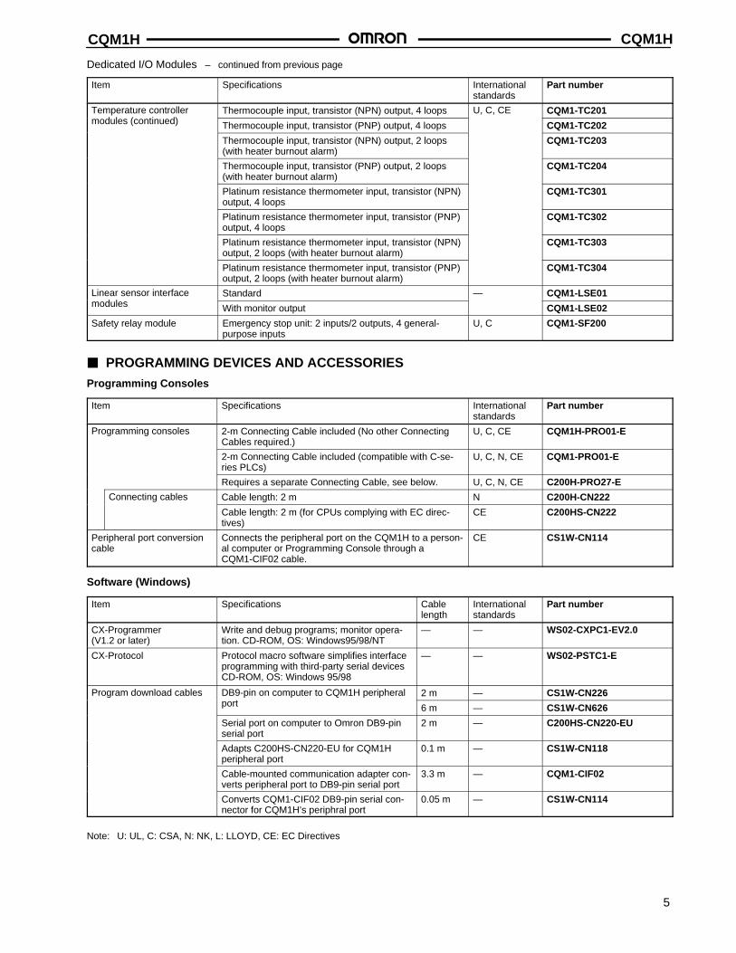
Dedicated I/O Modules – continued from previous page
Item Specifications Internationalstandards
Part number
Temperature controller Thermocouple input, transistor (NPN) output, 4 loops U, C, CE CQM1-TC201modules (continued) Thermocouple input, transistor (PNP) output, 4 loops CQM1-TC202
Thermocouple input, transistor (NPN) output, 2 loops(with heater burnout alarm)
CQM1-TC203
Thermocouple input, transistor (PNP) output, 2 loops(with heater burnout alarm)
CQM1-TC204
Platinum resistance thermometer input, transistor (NPN)output, 4 loops
CQM1-TC301
Platinum resistance thermometer input, transistor (PNP)output, 4 loops
CQM1-TC302
Platinum resistance thermometer input, transistor (NPN)output, 2 loops (with heater burnout alarm)
CQM1-TC303
Platinum resistance thermometer input, transistor (PNP)output, 2 loops (with heater burnout alarm)
CQM1-TC304
Linear sensor interface Standard — CQM1-LSE01modules With monitor output CQM1-LSE02
Safety relay module Emergency stop unit: 2 inputs/2 outputs, 4 general-purpose inputs
U, C CQM1-SF200
PROGRAMMING DEVICES AND ACCESSORIES
Programming Consoles
Item Specifications Internationalstandards
Part number
Programming consoles 2-m Connecting Cable included (No other ConnectingCables required.)
U, C, CE CQM1H-PRO01-E
2-m Connecting Cable included (compatible with C-se-ries PLCs)
U, C, N, CE CQM1-PRO01-E
Requires a separate Connecting Cable, see below. U, C, N, CE C200H-PRO27-E
Connecting cables Cable length: 2 m N C200H-CN222
Cable length: 2 m (for CPUs complying with EC direc-tives)
CE C200HS-CN222
Peripheral port conversioncable
Connects the peripheral port on the CQM1H to a person-al computer or Programming Console through aCQM1-CIF02 cable.
CE CS1W-CN114
Software (Windows)
Item Specifications Cablelength
Internationalstandards
Part number
CX-Programmer (V1.2 or later)
Write and debug programs; monitor opera-tion. CD-ROM, OS: Windows95/98/NT
— — WS02-CXPC1-EV2.0
CX-Protocol Protocol macro software simplifies interfaceprogramming with third-party serial devicesCD-ROM, OS: Windows 95/98
— — WS02-PSTC1-E
Program download cables DB9-pin on computer to CQM1H peripheral 2 m — CS1W-CN226port 6 m — CS1W-CN626
Serial port on computer to Omron DB9-pinserial port
2 m — C200HS-CN220-EU
Adapts C200HS-CN220-EU for CQM1H peripheral port
0.1 m — CS1W-CN118
Cable-mounted communication adapter con-verts peripheral port to DB9-pin serial port
3.3 m — CQM1-CIF02
Converts CQM1-CIF02 DB9-pin serial con-nector for CQM1H’s periphral port
0.05 m — CS1W-CN114
Note: U: UL, C: CSA, N: NK, L: LLOYD, CE: EC Directives
CQM1HCQM1H
6
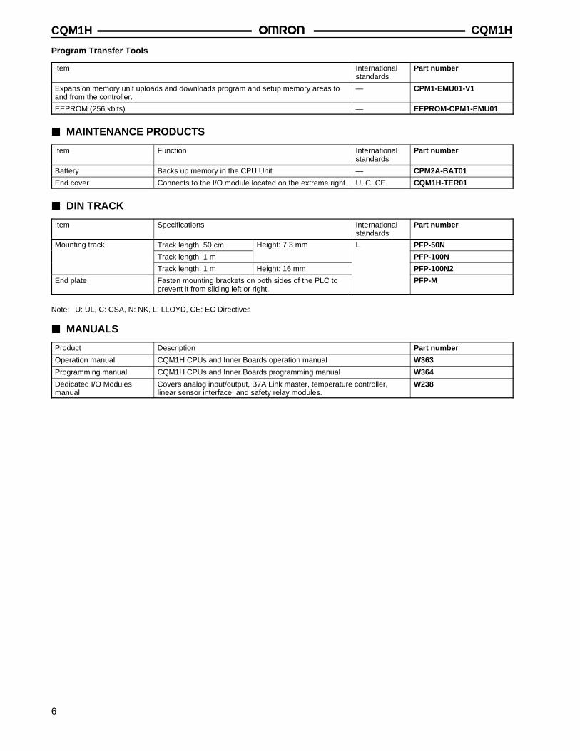
Program Transfer Tools
Item Internationalstandards
Part number
Expansion memory unit uploads and downloads program and setup memory areas toand from the controller.
— CPM1-EMU01-V1
EEPROM (256 kbits) — EEPROM-CPM1-EMU01
MAINTENANCE PRODUCTS
Item Function Internationalstandards
Part number
Battery Backs up memory in the CPU Unit. — CPM2A-BAT01
End cover Connects to the I/O module located on the extreme right U, C, CE CQM1H-TER01
DIN TRACK
Item Specifications Internationalstandards
Part number
Mounting track Track length: 50 cm Height: 7.3 mm L PFP-50N
Track length: 1 m PFP-100N
Track length: 1 m Height: 16 mm PFP-100N2
End plate Fasten mounting brackets on both sides of the PLC toprevent it from sliding left or right.
PFP-M
Note: U: UL, C: CSA, N: NK, L: LLOYD, CE: EC Directives
MANUALS
Product Description Part number
Operation manual CQM1H CPUs and Inner Boards operation manual W363
Programming manual CQM1H CPUs and Inner Boards programming manual W364
Dedicated I/O Modulesmanual
Covers analog input/output, B7A Link master, temperature controller,linear sensor interface, and safety relay modules.
W238
CQM1H CQM1H
7
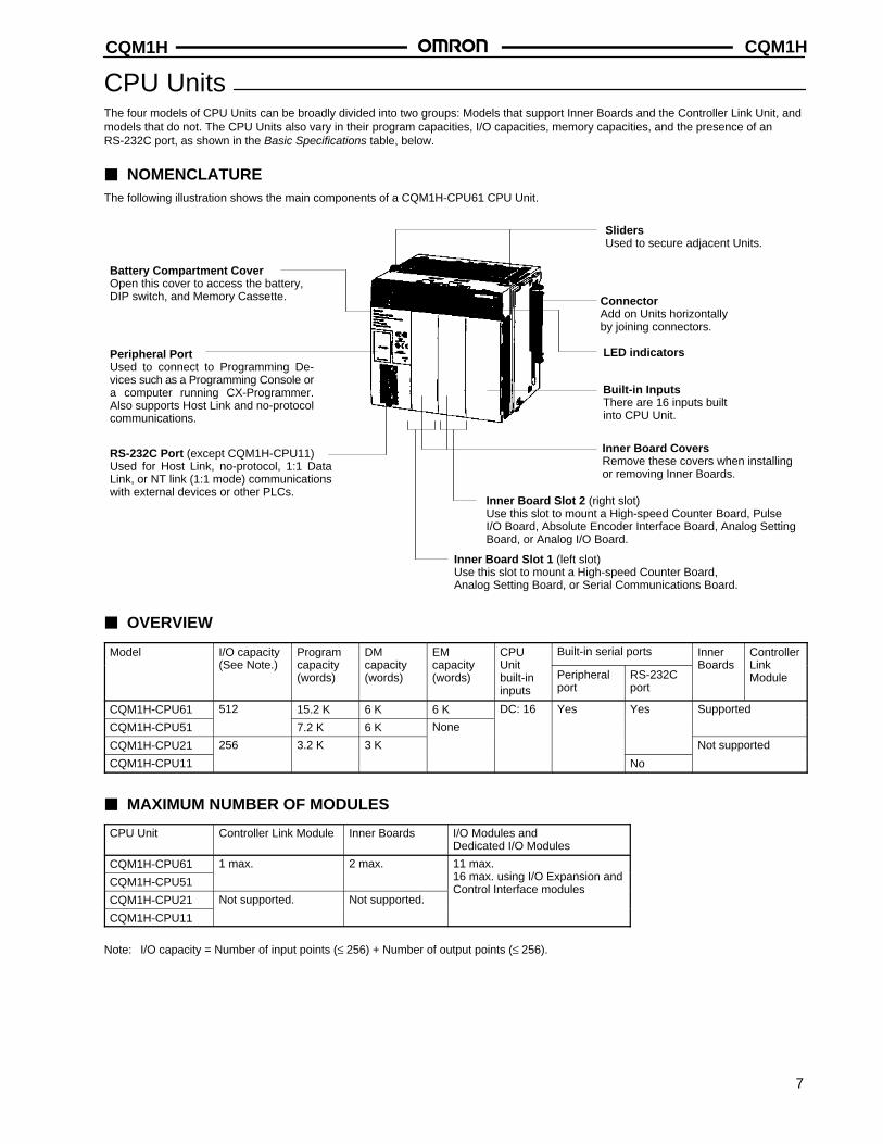
CPU UnitsThe four models of CPU Units can be broadly divided into two groups: Models that support Inner Boards and the Controller Link Unit, andmodels that do not. The CPU Units also vary in their program capacities, I/O capacities, memory capacities, and the presence of anRS-232C port, as shown in the Basic Specifications table, below.
NOMENCLATUREThe following illustration shows the main components of a CQM1H-CPU61 CPU Unit.
Peripheral PortUsed to connect to Programming De-vices such as a Programming Console ora computer running CX-Programmer.Also supports Host Link and no-protocolcommunications.
RS-232C Port (except CQM1H-CPU11)Used for Host Link, no-protocol, 1:1 DataLink, or NT link (1:1 mode) communicationswith external devices or other PLCs.
LED indicators
Inner Board Slot 1 (left slot)Use this slot to mount a High-speed Counter Board,Analog Setting Board, or Serial Communications Board.
Inner Board Slot 2 (right slot)Use this slot to mount a High-speed Counter Board, PulseI/O Board, Absolute Encoder Interface Board, Analog SettingBoard, or Analog I/O Board.
Battery Compartment CoverOpen this cover to access the battery,DIP switch, and Memory Cassette.
Inner Board CoversRemove these covers when installingor removing Inner Boards.
Built-in InputsThere are 16 inputs builtinto CPU Unit.
ConnectorAdd on Units horizontallyby joining connectors.
SlidersUsed to secure adjacent Units.
OVERVIEW
Model I/O capacity Program DM EM CPU Built-in serial ports Inner Controller(See Note.) capacity
(words)capacity(words)
capacity(words)
Unitbuilt-ininputs
Peripheralport
RS-232Cport
Boards Link Module
CQM1H-CPU61 512 15.2 K 6 K 6 K DC: 16 Yes Yes Supported
CQM1H-CPU51 7.2 K 6 K None
CQM1H-CPU21 256 3.2 K 3 K Not supported
CQM1H-CPU11 No
MAXIMUM NUMBER OF MODULES
CPU Unit Controller Link Module Inner Boards I/O Modules and Dedicated I/O Modules
CQM1H-CPU61 1 max. 2 max. 11 max.
CQM1H-CPU51 16 max. using I/O Expansion and
CQM1H-CPU21 Not supported. Not supported.Control Interface modules
CQM1H-CPU11
Note: I/O capacity = Number of input points (≤ 256) + Number of output points (≤ 256).
CQM1HCQM1H
8
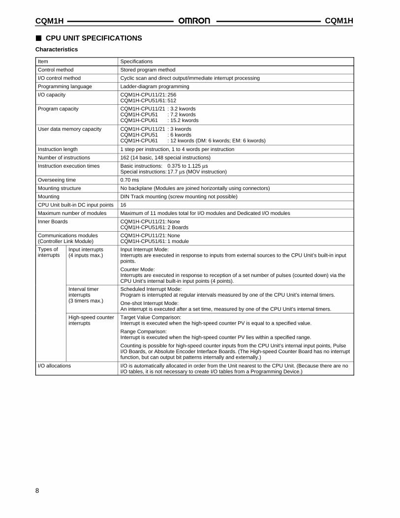
CPU UNIT SPECIFICATIONS
Characteristics
Item Specifications
Control method Stored program method
I/O control method Cyclic scan and direct output/immediate interrupt processing
Programming language Ladder-diagram programming
I/O capacity CQM1H-CPU11/21: 256CQM1H-CPU51/61: 512
Program capacity CQM1H-CPU11/21 : 3.2 kwordsCQM1H-CPU51 : 7.2 kwordsCQM1H-CPU61 : 15.2 kwords
User data memory capacity CQM1H-CPU11/21 : 3 kwordsCQM1H-CPU51 : 6 kwordsCQM1H-CPU61 : 12 kwords (DM: 6 kwords; EM: 6 kwords)
Instruction length 1 step per instruction, 1 to 4 words per instruction
Number of instructions 162 (14 basic, 148 special instructions)
Instruction execution times Basic instructions: 0.375 to 1.125 µsSpecial instructions: 17.7 µs (MOV instruction)
Overseeing time 0.70 ms
Mounting structure No backplane (Modules are joined horizontally using connectors)
Mounting DIN Track mounting (screw mounting not possible)
CPU Unit built-in DC input points 16
Maximum number of modules Maximum of 11 modules total for I/O modules and Dedicated I/O modules
Inner Boards CQM1H-CPU11/21: NoneCQM1H-CPU51/61: 2 Boards
Communications modules (Controller Link Module)
CQM1H-CPU11/21: NoneCQM1H-CPU51/61: 1 module
Types ofinterrupts
Input interrupts(4 inputs max.)
Input Interrupt Mode: Interrupts are executed in response to inputs from external sources to the CPU Unit’s built-in inputpoints.
Counter Mode: Interrupts are executed in response to reception of a set number of pulses (counted down) via theCPU Unit’s internal built-in input points (4 points).
Interval timer interrupts(3 timers max.)
Scheduled Interrupt Mode: Program is interrupted at regular intervals measured by one of the CPU Unit’s internal timers.
One-shot Interrupt Mode: An interrupt is executed after a set time, measured by one of the CPU Unit’s internal timers.
High-speed counterinterrupts
Target Value Comparison: Interrupt is executed when the high-speed counter PV is equal to a specified value.
Range Comparison: Interrupt is executed when the high-speed counter PV lies within a specified range.
Counting is possible for high-speed counter inputs from the CPU Unit’s internal input points, PulseI/O Boards, or Absolute Encoder Interface Boards. (The High-speed Counter Board has no interruptfunction, but can output bit patterns internally and externally.)
I/O allocations I/O is automatically allocated in order from the Unit nearest to the CPU Unit. (Because there are noI/O tables, it is not necessary to create I/O tables from a Programming Device.)
CQM1H CQM1H
9
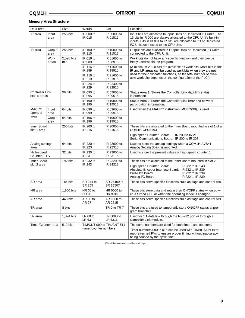
Memory Area Structure
Data area Size Words Bits Function
IR area Inputarea
256 bits IR 000 toIR 015
IR 00000 toIR 01515
Input bits are allocated to Input Units or Dedicated I/O Units. The16 bits in IR 000 are always allocated to the CPU Unit’s built-ininputs. Bits in IR 001 to IR 015 are allocated to I/O or DedicatedI/O Units connected to the CPU Unit.
IR area Outputarea
256 bits IR 100 toIR 115
IR 10000 toIR 11515
Output bits are allocated to Output Units or Dedicated I/O Unitsconnected to the CPU Unit.
Workareas
2,528 bitsmin.
IR 016 toIR 089
IR 01600 toIR 08915
Work bits do not have any specific function and they can befreely used within the program.
IR 116 toIR 189
IR 11600 toIR 18915
(A minimum 2,528 bits are available as work bits. Most bits in theIR and LR areas can be used as work bits when they are not
IR 216 toIR 219
IR 21600 toIR 21915
IR and LR areas can be used as work bits when they are notused for their allocated functions, so the total number of avail-able work bits depends on the configuration of the PLC.)
IR 224 toIR 229
IR 22400 toIR 22915
Controller Link status areas
96 bits IR 090 toIR 095
IR 09000 toIR 09515
Status Area 1: Stores the Controller Link data link status information.
IR 190 toIR 195
IR 19000 toIR 19515
Status Area 2: Stores the Controller Link error and network participation information.
MACROoperand
Inputarea
64 bits IR 096 toIR 099
IR 09600 toIR 09915
Used when the MACRO instruction, MCRO(99), is used.
area Outputarea
64 bits IR 196 toIR 199
IR 19600 toIR 19915
Inner Board slot 1 area
256 bits IR 200 toIR 215
IR 20000 toIR 21515
These bits are allocated to the Inner Board mounted in slot 1 of aCQM1H-CPU51/61.
High-speed Counter Board: IR 200 to IR 213Serial Communications Board: IR 200 to IR 207
Analog settingsarea
64 bits IR 220 toIR 223
IR 22000 toIR 22315
Used to store the analog settings when a CQM1H-AVB41 Analog Setting Board is mounted.
High-speed Counter, 0 PV
32 bits IR 230 toIR 231
IR 23000 toIR 23115
Used to store the present values of high-speed counter 0.
Inner Board slot 2 area
192 bits IR 232 toIR 243
IR 23200 toIR 24315
These bits are allocated to the Inner Board mounted in slot 2.
High-speed Counter Board: IR 232 to IR 243Absolute Encoder Interface Board: IR 232 to IR 239Pulse I/O Board: IR 232 to IR 239Analog I/O Board: IR 232 to IR 239
SR area 184 bits SR 244 toSR 255
SR 24400 toSR 25507
These bits serve specific functions such as flags and control bits.
HR area 1,600 bits HR 00 toHR 99
HR 0000 toHR 9915
These bits store data and retain their ON/OFF status when pow-er is turned OFF or when the operating mode is changed.
AR area 448 bits AR 00 toAR 27
AR 0000 toAR 2715
These bits serve specific functions such as flags and control bits.
TR area 8 bits — TR 0 to TR 7 These bits are used to temporarily store ON/OFF status at pro-gram branches.
LR area 1,024 bits LR 00 toLR 63
LR 0000 toLR 6315
Used for 1:1 data link through the RS-232 port or through a Controller Link module.
Timer/Counter area 512 bits TIM/CNT 000 to TIM/CNT 511(timer/counter numbers)
The same numbers are used for both timers and counters.
Timer numbers 000 to 015 can be used with TIMH(15) for inter-rupt-refreshed PVs to ensure proper timing without inaccuracybeing caused by the cycle time.
(This table continues on the next page.)
CQM1HCQM1H
10
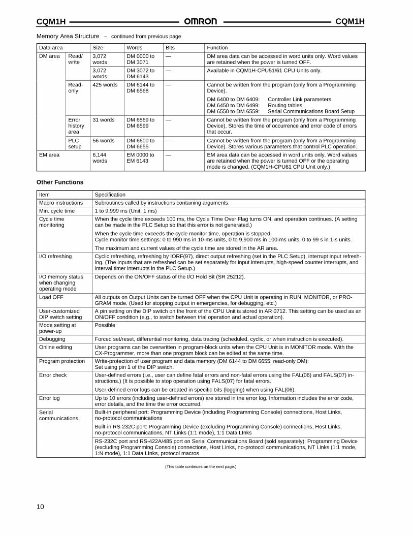
Memory Area Structure – continued from previous page
Data area Size Words Bits Function
DM area Read/write
3,072words
DM 0000 toDM 3071
— DM area data can be accessed in word units only. Word valuesare retained when the power is turned OFF.
3,072words
DM 3072 toDM 6143
— Available in CQM1H-CPU51/61 CPU Units only.
Read-only
425 words DM 6144 toDM 6568
— Cannot be written from the program (only from a ProgrammingDevice).
DM 6400 to DM 6409: Controller Link parametersDM 6450 to DM 6499: Routing tablesDM 6550 to DM 6559: Serial Communications Board Setup
Errorhistoryarea
31 words DM 6569 toDM 6599
— Cannot be written from the program (only from a ProgrammingDevice). Stores the time of occurrence and error code of errorsthat occur.
PLCsetup
56 words DM 6600 toDM 6655
— Cannot be written from the program (only from a ProgrammingDevice). Stores various parameters that control PLC operation.
EM area 6,144words
EM 0000 toEM 6143
— EM area data can be accessed in word units only. Word valuesare retained when the power is turned OFF or the operatingmode is changed. (CQM1H-CPU61 CPU Unit only.)
Other Functions
Item Specification
Macro instructions Subroutines called by instructions containing arguments.
Min. cycle time 1 to 9,999 ms (Unit: 1 ms)
Cycle time monitoring
When the cycle time exceeds 100 ms, the Cycle Time Over Flag turns ON, and operation continues. (A settingcan be made in the PLC Setup so that this error is not generated.)
When the cycle time exceeds the cycle monitor time, operation is stopped.Cycle monitor time settings: 0 to 990 ms in 10-ms units, 0 to 9,900 ms in 100-ms units, 0 to 99 s in 1-s units.
The maximum and current values of the cycle time are stored in the AR area.
I/O refreshing Cyclic refreshing, refreshing by IORF(97), direct output refreshing (set in the PLC Setup), interrupt input refresh-ing. (The inputs that are refreshed can be set separately for input interrupts, high-speed counter interrupts, andinterval timer interrupts in the PLC Setup.)
I/O memory statuswhen changing operating mode
Depends on the ON/OFF status of the I/O Hold Bit (SR 25212).
Load OFF All outputs on Output Units can be turned OFF when the CPU Unit is operating in RUN, MONITOR, or PRO-GRAM mode. (Used for stopping output in emergencies, for debugging, etc.)
User-customizedDIP switch setting
A pin setting on the DIP switch on the front of the CPU Unit is stored in AR 0712. This setting can be used as anON/OFF condition (e.g., to switch between trial operation and actual operation).
Mode setting atpower-up
Possible
Debugging Forced set/reset, differential monitoring, data tracing (scheduled, cyclic, or when instruction is executed).
Online editing User programs can be overwritten in program-block units when the CPU Unit is in MONITOR mode. With theCX-Programmer, more than one program block can be edited at the same time.
Program protection Write-protection of user program and data memory (DM 6144 to DM 6655: read-only DM):Set using pin 1 of the DIP switch.
Error check User-defined errors (i.e., user can define fatal errors and non-fatal errors using the FAL(06) and FALS(07) in-structions.) (It is possible to stop operation using FALS(07) for fatal errors.
User-defined error logs can be created in specific bits (logging) when using FAL(06).
Error log Up to 10 errors (including user-defined errors) are stored in the error log. Information includes the error code,error details, and the time the error occurred.
Serial communications
Built-in peripheral port: Programming Device (including Programming Console) connections, Host Links, no-protocol communications
Built-in RS-232C port: Programming Device (excluding Programming Console) connections, Host Links, no-protocol communications, NT Links (1:1 mode), 1:1 Data LInks
RS-232C port and RS-422A/485 port on Serial Communications Board (sold separately): Programming Device(excluding Programming Console) connections, Host Links, no-protocol communications, NT Links (1:1 mode,1:N mode), 1:1 Data LInks, protocol macros
(This table continues on the next page.)
CQM1H CQM1H
11
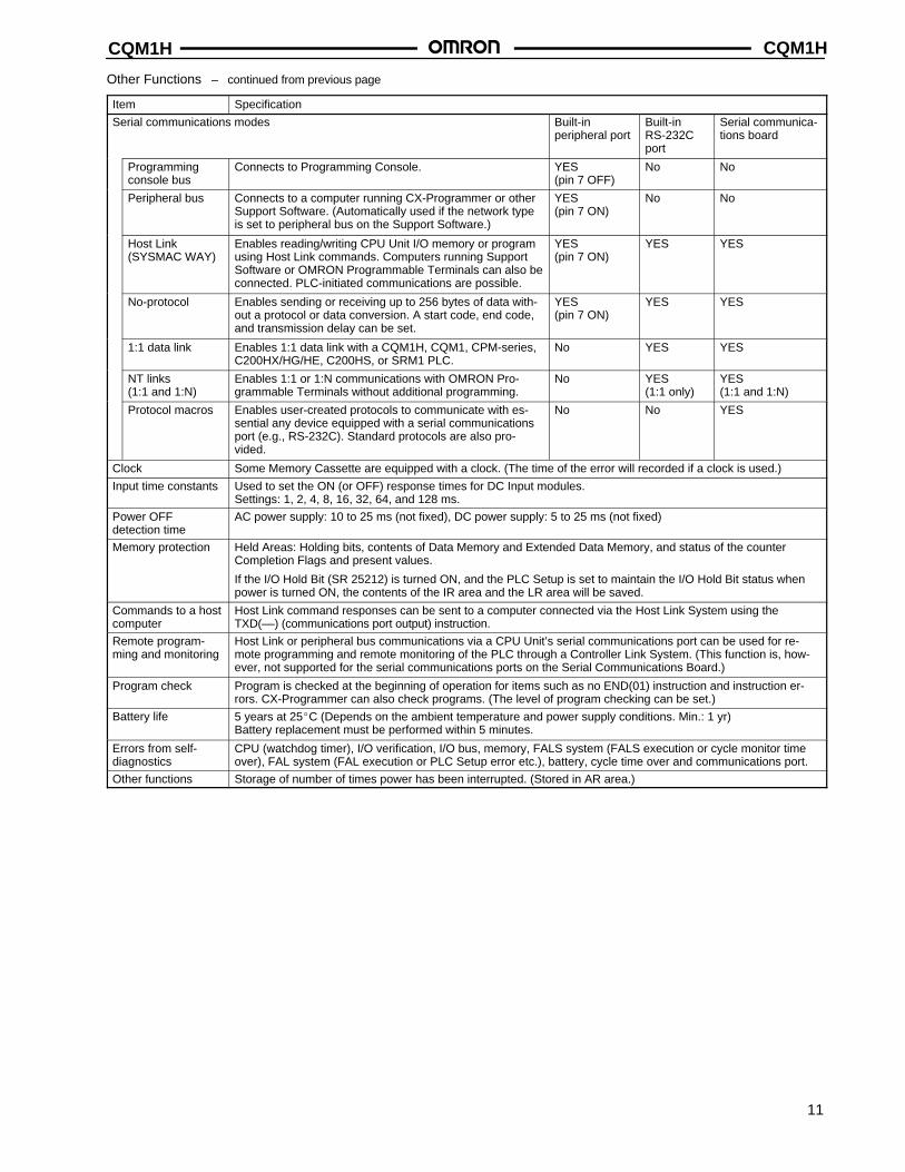
Other Functions – continued from previous page
Item Specification
Serial communications modes Built-in peripheral port
Built-inRS-232Cport
Serial communica-tions board
Programmingconsole bus
Connects to Programming Console. YES (pin 7 OFF)
No No
Peripheral bus Connects to a computer running CX-Programmer or otherSupport Software. (Automatically used if the network typeis set to peripheral bus on the Support Software.)
YES (pin 7 ON)
No No
Host Link (SYSMAC WAY)
Enables reading/writing CPU Unit I/O memory or programusing Host Link commands. Computers running SupportSoftware or OMRON Programmable Terminals can also beconnected. PLC-initiated communications are possible.
YES (pin 7 ON)
YES YES
No-protocol Enables sending or receiving up to 256 bytes of data with-out a protocol or data conversion. A start code, end code,and transmission delay can be set.
YES(pin 7 ON)
YES YES
1:1 data link Enables 1:1 data link with a CQM1H, CQM1, CPM-series,C200HX/HG/HE, C200HS, or SRM1 PLC.
No YES YES
NT links (1:1 and 1:N)
Enables 1:1 or 1:N communications with OMRON Pro-grammable Terminals without additional programming.
No YES (1:1 only)
YES (1:1 and 1:N)
Protocol macros Enables user-created protocols to communicate with es-sential any device equipped with a serial communicationsport (e.g., RS-232C). Standard protocols are also pro-vided.
No No YES
Clock Some Memory Cassette are equipped with a clock. (The time of the error will recorded if a clock is used.)
Input time constants Used to set the ON (or OFF) response times for DC Input modules. Settings: 1, 2, 4, 8, 16, 32, 64, and 128 ms.
Power OFF detection time
AC power supply: 10 to 25 ms (not fixed), DC power supply: 5 to 25 ms (not fixed)
Memory protection Held Areas: Holding bits, contents of Data Memory and Extended Data Memory, and status of the counterCompletion Flags and present values.
If the I/O Hold Bit (SR 25212) is turned ON, and the PLC Setup is set to maintain the I/O Hold Bit status whenpower is turned ON, the contents of the IR area and the LR area will be saved.
Commands to a hostcomputer
Host Link command responses can be sent to a computer connected via the Host Link System using theTXD(––) (communications port output) instruction.
Remote program-ming and monitoring
Host Link or peripheral bus communications via a CPU Unit’s serial communications port can be used for re-mote programming and remote monitoring of the PLC through a Controller Link System. (This function is, how-ever, not supported for the serial communications ports on the Serial Communications Board.)
Program check Program is checked at the beginning of operation for items such as no END(01) instruction and instruction er-rors. CX-Programmer can also check programs. (The level of program checking can be set.)
Battery life 5 years at 25C (Depends on the ambient temperature and power supply conditions. Min.: 1 yr)Battery replacement must be performed within 5 minutes.
Errors from self-diagnostics
CPU (watchdog timer), I/O verification, I/O bus, memory, FALS system (FALS execution or cycle monitor timeover), FAL system (FAL execution or PLC Setup error etc.), battery, cycle time over and communications port.
Other functions Storage of number of times power has been interrupted. (Stored in AR area.)
CQM1HCQM1H
12
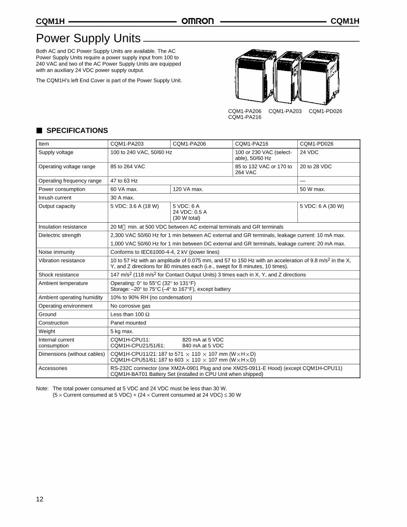
Power Supply UnitsBoth AC and DC Power Supply Units are available. The ACPower Supply Units require a power supply input from 100 to240 VAC and two of the AC Power Supply Units are equippedwith an auxiliary 24 VDC power supply output.
The CQM1H’s left End Cover is part of the Power Supply Unit.
CQM1-PA206CQM1-PA216
CQM1-PA203 CQM1-PD026
SPECIFICATIONS
Item CQM1-PA203 CQM1-PA206 CQM1-PA216 CQM1-PD026
Supply voltage 100 to 240 VAC, 50/60 Hz 100 or 230 VAC (select-able), 50/60 Hz
24 VDC
Operating voltage range 85 to 264 VAC 85 to 132 VAC or 170 to264 VAC
20 to 28 VDC
Operating frequency range 47 to 63 Hz —
Power consumption 60 VA max. 120 VA max. 50 W max.
Inrush current 30 A max.
Output capacity 5 VDC: 3.6 A (18 W) 5 VDC: 6 A 24 VDC: 0.5 A(30 W total)
5 VDC: 6 A (30 W)
Insulation resistance 20 M min. at 500 VDC between AC external terminals and GR terminals
Dielectric strength 2,300 VAC 50/60 Hz for 1 min between AC external and GR terminals, leakage current: 10 mA max.
1,000 VAC 50/60 Hz for 1 min between DC external and GR terminals, leakage current: 20 mA max.
Noise immunity Conforms to IEC61000-4-4, 2 kV (power lines)
Vibration resistance 10 to 57 Hz with an amplitude of 0.075 mm, and 57 to 150 Hz with an acceleration of 9.8 m/s2 in the X,Y, and Z directions for 80 minutes each (i.e., swept for 8 minutes, 10 times).
Shock resistance 147 m/s2 (118 m/s2 for Contact Output Units) 3 times each in X, Y, and Z directions
Ambient temperature Operating: 0° to 55°C (32° to 131°F)Storage: –20° to 75°C (–4° to 167°F), except battery
Ambient operating humidity 10% to 90% RH (no condensation)
Operating environment No corrosive gas
Ground Less than 100 ΩConstruction Panel mounted
Weight 5 kg max.
Internal current consumption
CQM1H-CPU11: 820 mA at 5 VDCCQM1H-CPU21/51/61: 840 mA at 5 VDC
Dimensions (without cables) CQM1H-CPU11/21: 187 to 571 110 107 mm (WHD)CQM1H-CPU51/61: 187 to 603 110 107 mm (WHD)
Accessories RS-232C connector (one XM2A-0901 Plug and one XM2S-0911-E Hood) (except CQM1H-CPU11)CQM1H-BAT01 Battery Set (installed in CPU Unit when shipped)
Note: The total power consumed at 5 VDC and 24 VDC must be less than 30 W.(5 × Current consumed at 5 VDC) + (24 × Current consumed at 24 VDC) ≤ 30 W
CQM1H CQM1H
13
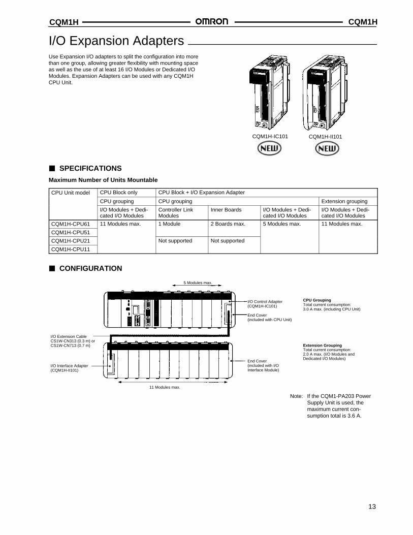
I/O Expansion AdaptersUse Expansion I/O adapters to split the configuration into morethan one group, allowing greater flexibility with mounting spaceas well as the use of at least 16 I/O Modules or Dedicated I/OModules. Expansion Adapters can be used with any CQM1HCPU Unit.
CQM1H-IC101 CQM1H-II101
SPECIFICATIONS
Maximum Number of Units Mountable
CPU Unit model CPU Block only CPU Block + I/O Expansion Adapter
CPU grouping CPU grouping Extension grouping
I/O Modules + Dedi-cated I/O Modules
Controller Link Modules
Inner Boards I/O Modules + Dedi-cated I/O Modules
I/O Modules + Dedi-cated I/O Modules
CQM1H-CPU61 11 Modules max. 1 Module 2 Boards max. 5 Modules max. 11 Modules max.
CQM1H-CPU51
CQM1H-CPU21 Not supported Not supported
CQM1H-CPU11
CONFIGURATION
5 Modules max.
I/O Control Adapter(CQM1H-IC101)
End Cover (included with CPU Unit)
End Cover (included with I/O Interface Module)
11 Modules max.
Extension GroupingTotal current consumption: 2.0 A max. (I/O Modules and Dedicated I/O Modules)
I/O Interface Adapter (CQM1H-II101)
CPU GroupingTotal current consumption:3.0 A max. (including CPU Unit)
I/O Extension CableCS1W-CN313 (0.3 m) orCS1W-CN713 (0.7 m)
Note: If the CQM1-PA203 PowerSupply Unit is used, themaximum current con-sumption total is 3.6 A.

CQM1HCQM1H
14
Memory CassettesAn optional Memory Cassette can be used to store the user program, PLC setup, and other data in ROM so that vital data will not be lostin the event of battery expiration or careless programming/monitoring operations.
If the PLC’s settings need to be changed to execute another process, the entire software setup and user program can be changed just byexchanging the Memory Cassette and rebooting the PLC.
EEPROM:
CQM1-ME04KCQM1-ME04RCQM1-ME08KCQM1-ME08R
Flash Memory:
CQM1H-ME16KCQM1H-ME16R
EPROM:
CQM1-MP08KCQM1-MP08R
SPECIFICATIONS
Memory Model Specifications
EEPROM CQM1-ME04K 4 kwords without clock
CQM1-ME04R 4 kwords with clock
CQM1-ME08K 8 kwords without clock
CQM1-ME08R 8 kwords with clock
EPROM CQM1-MP08K Without clock (see below)
CQM1-MP08R With clock (see below)
Flash CQM1H-ME16K 16 kwords without clock
CQM1H-ME16R 16 kwords with clock
Memory Cassette (EEPROM or flash memory)
Mounted from the front of the CPU Unit and used to store and read the user’s program,DM (read-only DM and PLC Setup), and expansion instruction information as one block.It is possible to set the CPU Unit so that data stored in the Memory Cassette (user’sprogram, DM, expansion instruction information) is automatically sent to the CPU Unit(auto-boot) at startup. Transfer and comparison of data between the CPU Unit andMemory Cassette are possible using AR area control bits.
EPROM Chips
The following EPROM chips (sold separately) are required for EPROM Memory Cassettes. The chip is mounted in the I/O socket on the Memory Cassette.
Model ROM version Capacity Access speed
ROM-ID-B 27128 or equivalent 8 kwords 150 ns
ROM-JD-B 27256 or equivalent 16 kwords 150 ns
ROM-KD-B 27512 or equivalent 32 kwords 150 ns
CQM1H CQM1H
15
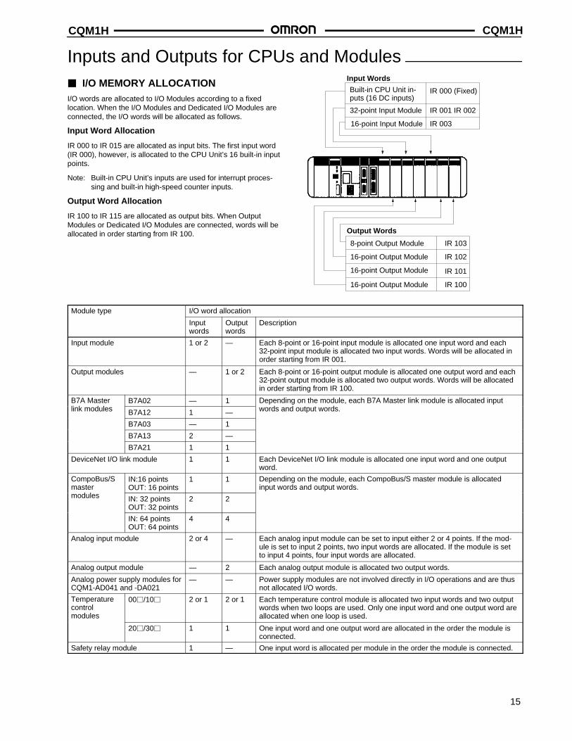
Inputs and Outputs for CPUs and Modules I/O MEMORY ALLOCATIONI/O words are allocated to I/O Modules according to a fixedlocation. When the I/O Modules and Dedicated I/O Modules areconnected, the I/O words will be allocated as follows.
Input Word Allocation
IR 000 to IR 015 are allocated as input bits. The first input word(IR 000), however, is allocated to the CPU Unit’s 16 built-in inputpoints.
Note: Built-in CPU Unit’s inputs are used for interrupt proces-sing and built-in high-speed counter inputs.
Output Word Allocation
IR 100 to IR 115 are allocated as output bits. When OutputModules or Dedicated I/O Modules are connected, words will beallocated in order starting from IR 100.
Input Words
Built-in CPU Unit in-puts (16 DC inputs)
32-point Input Module
16-point Input Module
IR 000 (Fixed)
IR 001 IR 002
IR 003
IR 101
Output Words
8-point Output Module
16-point Output Module
16-point Output Module
16-point Output Module
IR 103
IR 102
IR 100
Module type I/O word allocation
Inputwords
Outputwords
Description
Input module 1 or 2 — Each 8-point or 16-point input module is allocated one input word and each32-point input module is allocated two input words. Words will be allocated inorder starting from IR 001.
Output modules — 1 or 2 Each 8-point or 16-point output module is allocated one output word and each32-point output module is allocated two output words. Words will be allocatedin order starting from IR 100.
B7A Master B7A02 — 1 Depending on the module, each B7A Master link module is allocated inputlink modules B7A12 1 — words and output words.
B7A03 — 1
B7A13 2 —
B7A21 1 1
DeviceNet I/O link module 1 1 Each DeviceNet I/O link module is allocated one input word and one outputword.
CompoBus/Smaster
IN:16 points OUT: 16 points
1 1 Depending on the module, each CompoBus/S master module is allocatedinput words and output words.
modules IN: 32 pointsOUT: 32 points
2 2
IN: 64 pointsOUT: 64 points
4 4
Analog input module 2 or 4 — Each analog input module can be set to input either 2 or 4 points. If the mod-ule is set to input 2 points, two input words are allocated. If the module is setto input 4 points, four input words are allocated.
Analog output module — 2 Each analog output module is allocated two output words.
Analog power supply modules forCQM1-AD041 and -DA021
— — Power supply modules are not involved directly in I/O operations and are thusnot allocated I/O words.
Temperaturecontrol modules
00/10 2 or 1 2 or 1 Each temperature control module is allocated two input words and two outputwords when two loops are used. Only one input word and one output word areallocated when one loop is used.
20/30 1 1 One input word and one output word are allocated in the order the module isconnected.
Safety relay module 1 — One input word is allocated per module in the order the module is connected.
CQM1HCQM1H
16
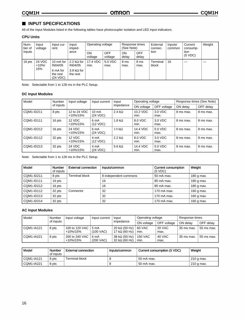
INPUT SPECIFICATIONSAll of the Input Modules listed in the following tables have photocoupler isolation and LED input indicators.
CPU Units
Num-ber of
Inputvoltage
Input cur-rent
Inputimped-
Operating voltage Response times(See Note)
Externalconnec-
Inputs/common
Currentconsump-
Weight
inputs ance ON voltage
OFF voltage
ON delay
OFFdelay
tion tion (5 VDC)
16 pts 24 VDC+10%/15%
10 mA forIN04/05
6 mA forthe rest(24 VDC)
2.2 kΩ forIN04/05
3.9 kΩ forthe rest
17.4 VDCmin.
5.0 VDCmax.
8 msmax.
8 msmax.
Terminalblock
16 — —
Note: Selectable from 1 to 128 ms in the PLC Setup.
DC Input Modules
Model Number Input voltage Input current Input Operating voltage Response times (See Note)of inputs impedance ON voltage OFF voltage ON delay OFF delay
CQM1-ID211 8 pts 12 to 24 VDC+10%/15%
10 mA(24 VDC)
2.4 kΩ 10.2 VDCmin.
3.0 VDCmax.
8 ms max. 8 ms max.
CQM1-ID111 16 pts 12 VDC+10%/15%
6 mA(12 VDC)
1.8 kΩ 8.0 VDCmin.
3.0 VDCmax.
8 ms max. 8 ms max.
CQM1-ID212 16 pts 24 VDC+10%/15%
6 mA(24 VDC)
3.9 kΩ 14.4 VDCmin.
5.0 VDCmax.
8 ms max. 8 ms max.
CQM1-ID112 32 pts 12 VDC+10%/15%
4 mA(12 VDC)
2.2 kΩ 8.0 VDCmin.
3.0 VDCmax.
8 ms max. 8 ms max.
CQM1-ID213 32 pts 24 VDC+10%/15%
4 mA(24 VDC)
5.6 kΩ 14.4 VDCmin.
5.0 VDCmax.
8 ms max. 8 ms max.
Note: Selectable from 1 to 128 ms in the PLC Setup.
Model Number External connection Inputs/common Current consumption WeightModel Numberof inputs
External connection Inputs/common Current consumption(5 VDC)
Weight
CQM1-ID211 8 pts Terminal block 8 independent commons 50 mA max. 180 g max.
CQM1-ID111 16 pts 16 85 mA max. 180 g max.
CQM1-ID212 16 pts 16 85 mA max. 180 g max.
CQM1-ID112 32 pts Connector 32 170 mA max. 160 g max.
CQM1-ID213 32 pts 32 170 mA max. 160 g max.
CQM1-ID214 32 pts 32 170 mA max. 160 g max.
AC Input Modules
Model Number Input voltage Input current Input Operating voltage Response timesof inputs impedance ON voltage OFF voltage ON delay OFF delay
CQM1-IA121 8 pts 100 to 120 VAC+10%/15%
5 mA(100 VAC)
20 kΩ (50 Hz)17 kΩ (60 Hz)
60 VACmin.
20 VACmax.
35 ms max. 55 ms max.
CQM1-IA221 8 pts 200 to 240 VAC+10%/15%
6 mA(200 VAC)
38 kΩ (50 Hz)32 kΩ (60 Hz)
150 VACmin.
40 VACmax.
35 ms max. 55 ms max.
Model Number External connection Inputs/common Current consumption (5 VDC) WeightModel Numberof inputs
External connection Inputs/common Current consumption (5 VDC) Weight
CQM1-IA121 8 pts Terminal block 8 50 mA max. 210 g max.
CQM1-IA221 8 pts 8 50 mA max. 210 g max.
CQM1H CQM1H
17
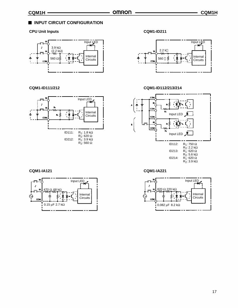
INPUT CIRCUIT CONFIGURATION
CPU Unit Inputs
3.9 kΩ(2.2 kΩ)
Input LED
InternalCircuits560 Ω
CQM1-ID211
2.2 k
Input LED
InternalCircuits560
CQM1-ID111/212 CQM1-ID112/213/214
Input LED
InternalCircuits
ID111: R1: 1.8 kΩR2: 620 Ω
ID212: R1: 3.9 kΩR2: 560 Ω ID112: R1: 750 Ω
R2: 2.2 kΩID213: R1: 620 Ω
R2: 5.6 kΩID214: R1: 620 Ω
R2: 3.9 kΩ
CQM1-IA121 CQM1-IA221
470 Ω
Input LED
InternalCircuits
2.7 kΩ0.15 µF
68 kΩ 820 Ω
Input LED
InternalCircuits
8.2 kΩ0.082 µF
220 kΩ
Input LED
Input LED
CQM1HCQM1H
18
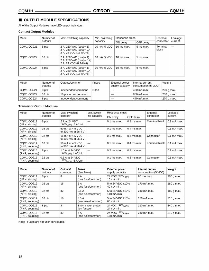
OUTPUT MODULE SPECIFICATIONSAll of the Output Modules have LED output indicators.
Contact Output Modules
Model Number of Max. switching capacity Min. switching Response times External Leakageoutputs capacity ON delay OFF delay connector current
CQM1-OC221 8 pts 2 A, 250 VAC (cosφ= 1)2 A, 250 VAC (cosφ= 0.4)2 A, 24 VDC (16 A/Unit)
10 mA, 5 VDC 10 ms max. 5 ms max. Terminalblock
—
CQM1-OC222 16 pts 2 A, 250 VAC (cosφ= 1)2 A, 250 VAC (cosφ= 0.4)2 A, 24 VDC (8 A/Unit)
10 mA, 5 VDC 10 ms max. 5 ms max.
CQM1-OC224 8 pts 2 A, 250 VAC (cosφ= 1)2 A, 250 VAC (cosφ= 0.4)2 A, 24 VDC (16 A/Unit)
10 mA, 5 VDC 15 ms max. 5 ms max.
Model Number of outputs
Outputs/common Fuses External powersupply capacity
Internal current consumption (5 VDC)
Weight
CQM1-OC221 8 pts Independent commons None — 430 mA max. 200 g max.
CQM1-OC222 16 pts 16 pts to one common — 850 mA max. 230 g max.
CQM1-OC224 8 pts Independent commons — 440 mA max. 270 g max.
Transistor Output Modules
Model Number of Max. switching Min. switch- Response times External Leakage outputs capacity ing capacity ON delay OFF delay connector current
CQM1-OD211(NPN, sinking)
8 pts 2 A at 24 VDC+10%/–15% 5 A/Unit
— 0.1 ms max. 0.3 ms max. Terminal block 0.1 mA max.
CQM1-OD212(NPN, sinking)
16 pts 50 mA at 4.5 VDCto 300 mA at 26.4 V
— 0.1 ms max. 0.4 ms max. 0.1 mA max.
CQM1-OD213(NPN, sinking)
32 pts 16 mA at 4.5 VDCto 100 mA at 26.4 V
— 0.1 ms max. 0.4 ms max. Connector 0.1 mA max.
CQM1-OD214(PNP, sourcing)
16 pts 50 mA at 4.5 VDCto 300 mA at 26.4 V
— 0.1 ms max. 0.4 ms max. Terminal block 0.1 mA max.
CQM1-OD215(PNP, sourcing)
8 pts 1.0 A at 24 VDC+10%/–15% 4 A/Unit
— 0.2 ms max. 0.8 ms max. 0.1 mA max.
CQM1-OD216(PNP, sourcing)
32 pts 0.5 A at 24 VDC+10%/–15% 5 A/Unit
— 0.1 ms max. 0.3 ms max. Connector 0.1 mA max.
Model Number of Outputs/ Fuses External power Internal current WeightModel Number of outputs
Outputs/common
Fuses(See Note)
External power supply capacity
Internal current consumption (5 VDC)
Weight
CQM1-OD211(NPN, sinking)
8 pts 8 7 A(one fuse/common)
24 VDC +10%/–15% 15 mA min.
90 mA max. 200 g max.
CQM1-OD212(NPN, sinking)
16 pts 16 5 A(one fuse/common)
5 to 24 VDC ±10%40 mA min.
170 mA max. 180 g max.
CQM1-OD213(NPN, sinking)
32 pts 32 3.5 A(one fuse/common)
5 to 24 VDC ±10%110 mA min.
240 mA max. 180 g max.
CQM1-OD214(PNP, sourcing)
16 pts 16 3.5 A(two fuses/common)
5 to 24 VDC ±10%60 mA min.
170 mA max. 210 g max.
CQM1-OD215(PNP, sourcing)
8 pts 8 Short-circuit protec-tion function
24 VDC +10%/–15% 24 mA min.
110 mA max. 240 g max.
CQM1-OD216(PNP, sourcing)
32 pts 32 7 A(one fuse/common)
24 VDC +10%/–15%160 mA min.
240 mA max. 210 g max.
Note: Fuses are not user-serviceable.
CQM1H CQM1H
19
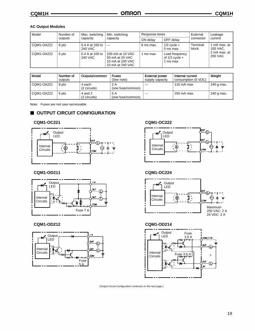
AC Output Modules
Model Number of Max. switching Min. switching Response times External Leakage outputs capacity capacity ON delay OFF delay connector current
CQM1-OA221 8 pts 0.4 A at 100 to240 VAC
— 6 ms max. 1/2 cycle + 5 ms max.
Terminalblock
1 mA max. at100 VAC,
CQM1-OA222 6 pts 0.4 A at 100 to240 VAC
100 mA at 10 VAC50 mA at 24 VAC10 mA at 100 VAC10 mA at 240 VAC
1 ms max. Load frequencyof 1/2 cycle + 1 ms max.
2 mA max. at200 VAC
Model Number of Outputs/common Fuses External power Internal current WeightModel Number of outputs
Outputs/common Fuses(See note)
External powersupply capacity
Internal current consumption (5 VDC)
Weight
CQM1-OA221 8 pts 4 each(2 circuits)
2 A(one fuse/common)
— 110 mA max. 240 g max.
CQM1-OA222 6 pts 4 and 2(2 circuits)
5 A(one fuse/common)
— 250 mA max. 240 g max.
Note: Fuses are not user-serviceable.
OUTPUT CIRCUIT CONFIGURATION
CQM1-OC221
OutputLED
InternalCircuits
CQM1-OC222
OutputLED
InternalCircuits
CQM1-OD211 CQM1-OC224
OutputLED
InternalCircuits
Maximum250 VAC: 2 A24 VDC: 2 A
CQM1-OD212 CQM1-OD214
Fuse5 A
OutputLED
InternalCircuits
OutputLED
InternalCircuits
Fuse3.5 A
Fuse 3.5 A
OutputLED
InternalCircuits
Fuse 7 A
(Output Circuit Configuration continues on the next page.)
CQM1HCQM1H
20
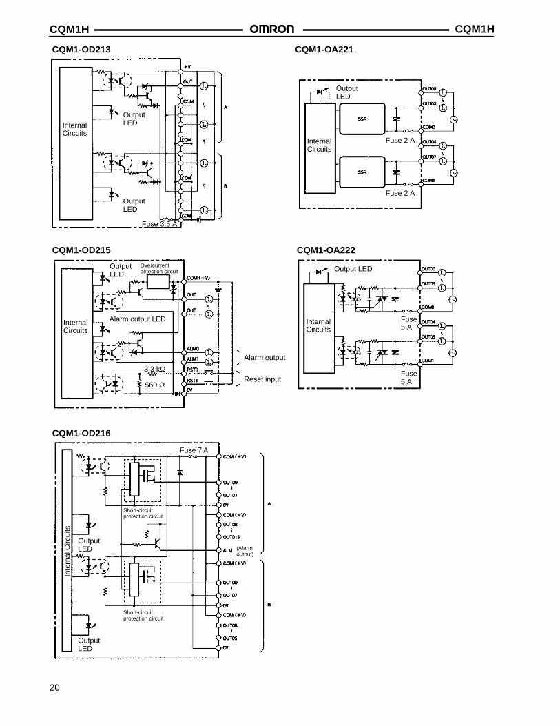
CQM1-OD213 CQM1-OA221
InternalCircuits
OutputLED
OutputLED
Fuse 3.5 A
InternalCircuits
OutputLED
Fuse 2 A
Fuse 2 A
CQM1-OD215 CQM1-OA222
Output LED
InternalCircuits
Fuse5 A
Fuse5 A
CQM1-OD216
InternalCircuits
OutputLED
3.3 kΩ
560 Ω
Fuse 7 A
OutputLED
OutputLED
Inte
rnal
Circ
uits
Overcurrentdetection circuit
Alarm output LED
Alarm output
Reset input
Short-circuitprotection circuit
Short-circuitprotection circuit
(Alarmoutput)
CQM1H CQM1H
21
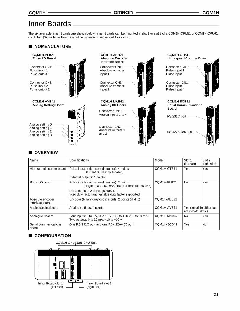
Inner BoardsThe six available Inner Boards are shown below. Inner Boards can be mounted in slot 1 or slot 2 of a CQM1H-CPU51 or CQM1H-CPU61CPU Unit. (Some Inner Boards must be mounted in either slot 1 or slot 2.)
NOMENCLATURE
CQM1H-PLB21Pulse I/O Board
Connector CN1:Pulse input 1Pulse output 1
Connector CN2:Pulse input 2Pulse output 2
CQM1H-ABB21Absolute EncoderInterface Board
Connector CN1:Absolute encoderinput 1
Connector CN2:Absolute encoderinput 2
CQM1H-CTB41High-speed Counter Board
Connector CN1:Pulse input 1Pulse input 2
Connector CN2:Pulse input 3Pulse input 4
CQM1H-AVB41Analog Setting Board
Analog setting 0Analog setting 1Analog setting 2Analog setting 3
CQM1H-MAB42Analog I/O Board
Connector CN1:Analog inputs 1 to 4
Connector CN2:Absolute outputs 1and 2
CQM1H-SCB41Serial CommunicationsBoard
RS-232C port
RS-422A/485 port
OVERVIEW
Name Specifications Model Slot 1(left slot)
Slot 2(right slot)
High-speed counter board Pulse inputs (high-speed counter): 4 points(50 kHz/500 kHz switchable)
External outputs: 4 points
CQM1H-CTB41 Yes Yes
Pulse I/O board Pulse inputs (high-speed counter): 2 points (single-phase: 50 kHz, phase difference: 25 kHz)
Pulse outputs: 2 points (50 kHz), fixed duty factor and variable duty factor supported
CQM1H-PLB21 No Yes
Absolute encoder interface board
Encoder (binary gray code) inputs: 2 points (4 kHz) CQM1H-ABB21
Analog setting board Analog settings: 4 points CQM1H-AVB41 Yes (Install in either butnot in both slots.)
Analog I/O board Four inputs: 0 to 5 V, 0 to 10 V, –10 to +10 V, 0 to 20 mATwo outputs: 0 to 20 mA, –10 to +10 V
CQM1H-MAB42 No Yes
Serial communicationsboard
One RS-232C port and one RS-422A/485 port CQM1H-SCB41 Yes No
CONFIGURATION
CQM1H-CPU51/61 CPU Unit
Inner Board slot 1(left slot)
Inner Board slot 2(right slot)
CQM1HCQM1H
22
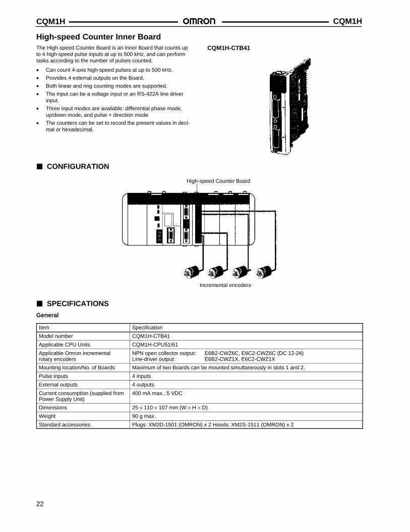
High-speed Counter Inner BoardThe High-speed Counter Board is an Inner Board that counts upto 4 high-speed pulse inputs at up to 500 kHz, and can performtasks according to the number of pulses counted.
• Can count 4-axis high-speed pulses at up to 500 kHz.
• Provides 4 external outputs on the Board.
• Both linear and ring counting modes are supported.
• The input can be a voltage input or an RS-422A line driverinput.
• Three input modes are available: differential phase mode,up/down mode, and pulse + direction mode
• The counters can be set to record the present values in deci-mal or hexadecimal.
CQM1H-CTB41
CONFIGURATION
High-speed Counter Board
Incremental encoders
SPECIFICATIONS
General
Item Specification
Model number CQM1H-CTB41
Applicable CPU Units CQM1H-CPU51/61
Applicable Omron incremental rotary encoders
NPN open collector output: E6B2-CWZ6C, E6C2-CWZ6C (DC 12-24)Line-driver output: E6B2-CWZ1X, E6C2-CWZ1X
Mounting location/No. of Boards Maximum of two Boards can be mounted simultaneously in slots 1 and 2.
Pulse inputs 4 inputs
External outputs 4 outputs
Current consumption (supplied fromPower Supply Unit)
400 mA max., 5 VDC
Dimensions 25 × 110 × 107 mm (W × H × D)
Weight 90 g max.
Standard accessories Plugs: XM2D-1501 (OMRON) x 2 Hoods: XM2S-1511 (OMRON) x 2
CQM1H CQM1H
23
High-speed Counter Inner Board
Pulse Input Functions
Item Specification
Number of counters 4 counters (4 ports)
Input modes (Set in the PLC Setup.) Differential phase inputs Up/Down pulse inputs Pulse/Direction inputs
Input method Switching between inputs using phasedifference multiples of 1x, 2x, or 4x.(Set in the PLC Setup.)
Two single-phase inputs Single-phase pulse anddirection inputs
Count frequency (Set for each port in the PLC Setup.)
25 kHz (default) or 250 kHz 50 kHz (default) or500 kHz
50 kHz (default) or500 kHz
Count values Linear counting: –8388608 to 8388607 BCD, F8000000 to 07FFFFFF HexRing counting: 00000000 to 08388607 BCD, 00000000 to 07FFFFFF Hex
Control Target value comparison Up to 48 target values and external/internal output bit patterns registered.method Range comparison Up to 16 upper limits, lower limits, and external/internal output bit patterns registered.
Pulse Input Ratings
Item Specification
Number of pulse inputs 4 inputs (Ports 1 to 4 = High-speed counters 1 to 4)
Signals Encoder inputs A and B; pulse input Z
Input voltage Switched by means of input voltage switch on the Board (Specified separately for phases A, B, and Z.)
24 VDC±10% RS-422A line driver (AM26LS31 or equivalent)
Phase A and B Phase Z Phase A and B Phase Z
Input current 5 mA typical 8 mA typical 10 mA typical 13 mA typical
ON voltage 19.6 VDC min. 18.6 VDC min. — —
OFF voltage 4.0 VDC min. 4.0 VDC min. — —
External Output Ratings
Item Specification
Number of external outputs 4 transistor outputs (The four outputs are set together as sinking or sourcing outputs in the PLC Setup.)
Function The target comparison or range comparison results of high-speed counters 1 to 4 output fouruser-defined 4-bit external bit patterns (bits 08 to 11 of either IR 208 to IR 211 or IR 240 toIR 243). An OR is taken of corresponding bits in these four bit patterns, and the result is outputon external outputs 1 to 4.
External power supply 5 to 24 VDC±10%
Switching capacity 16 mA/4.5 VDC to 80 mA/26.4 V
Leakage current 0.1 mA max.
Residual voltage 0.8 V max.
Response time ON response: 0.1 ms max.; OFF response: 0.4 ms max.
CQM1HCQM1H
24
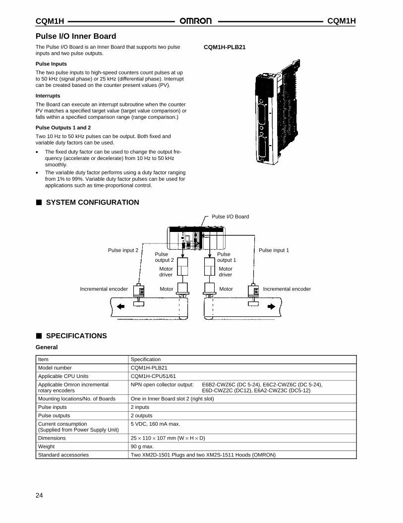
Pulse I/O Inner BoardThe Pulse I/O Board is an Inner Board that supports two pulseinputs and two pulse outputs.
Pulse Inputs
The two pulse inputs to high-speed counters count pulses at upto 50 kHz (signal phase) or 25 kHz (differential phase). Interruptcan be created based on the counter present values (PV).
Interrupts
The Board can execute an interrupt subroutine when the counterPV matches a specified target value (target value comparison) orfalls within a specified comparison range (range comparison.)
Pulse Outputs 1 and 2
Two 10 Hz to 50 kHz pulses can be output. Both fixed andvariable duty factors can be used.
• The fixed duty factor can be used to change the output fre-quency (accelerate or decelerate) from 10 Hz to 50 kHzsmoothly.
• The variable duty factor performs using a duty factor rangingfrom 1% to 99%. Variable duty factor pulses can be used forapplications such as time-proportional control.
CQM1H-PLB21
SYSTEM CONFIGURATION
Pulse I/O Board
Pulse input 2
Incremental encoder
Motordriver
Pulseoutput 2
Motor Motor
Motordriver
Pulse input 1
Incremental encoder
Pulseoutput 1
SPECIFICATIONS
General
Item Specification
Model number CQM1H-PLB21
Applicable CPU Units CQM1H-CPU51/61
Applicable Omron incremental rotary encoders
NPN open collector output: E6B2-CWZ6C (DC 5-24), E6C2-CWZ6C (DC 5-24), E6D-CWZ2C (DC12), E6A2-CWZ3C (DC5-12)
Mounting locations/No. of Boards One in Inner Board slot 2 (right slot)
Pulse inputs 2 inputs
Pulse outputs 2 outputs
Current consumption (Supplied from Power Supply Unit)
5 VDC, 160 mA max.
Dimensions 25 × 110 × 107 mm (W × H × D)
Weight 90 g max.
Standard accessories Two XM2D-1501 Plugs and two XM2S-1511 Hoods (OMRON)
CQM1H CQM1H
25
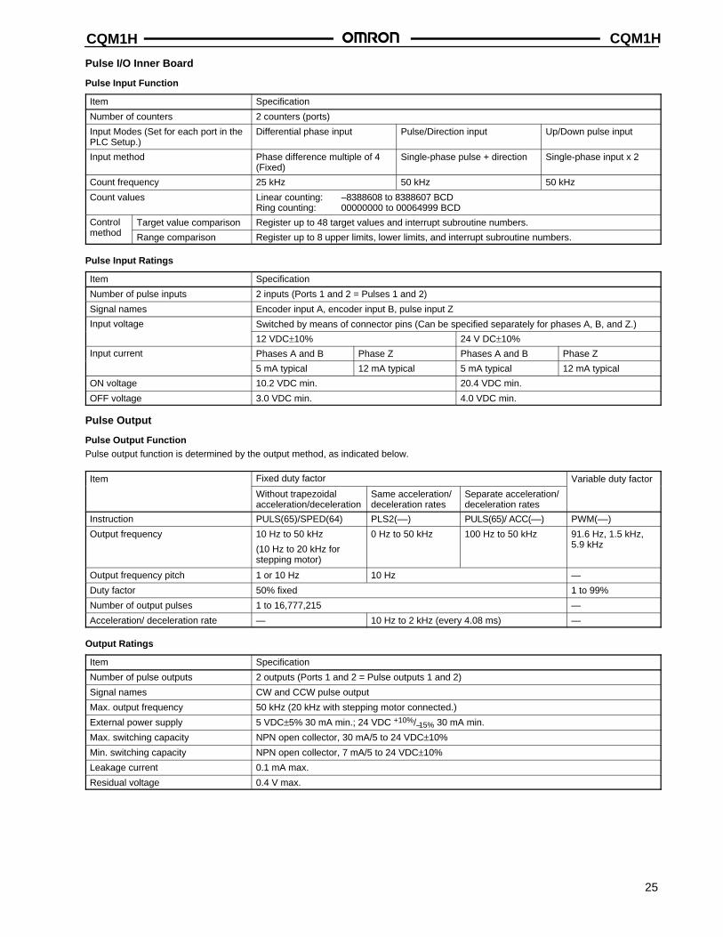
Pulse I/O Inner Board
Pulse Input Function
Item Specification
Number of counters 2 counters (ports)
Input Modes (Set for each port in thePLC Setup.)
Differential phase input Pulse/Direction input Up/Down pulse input
Input method Phase difference multiple of 4(Fixed)
Single-phase pulse + direction Single-phase input x 2
Count frequency 25 kHz 50 kHz 50 kHz
Count values Linear counting: –8388608 to 8388607 BCDRing counting: 00000000 to 00064999 BCD
Control Target value comparison Register up to 48 target values and interrupt subroutine numbers.method Range comparison Register up to 8 upper limits, lower limits, and interrupt subroutine numbers.
Pulse Input Ratings
Item Specification
Number of pulse inputs 2 inputs (Ports 1 and 2 = Pulses 1 and 2)
Signal names Encoder input A, encoder input B, pulse input Z
Input voltage Switched by means of connector pins (Can be specified separately for phases A, B, and Z.)
12 VDC±10% 24 V DC±10%
Input current Phases A and B Phase Z Phases A and B Phase Z
5 mA typical 12 mA typical 5 mA typical 12 mA typical
ON voltage 10.2 VDC min. 20.4 VDC min.
OFF voltage 3.0 VDC min. 4.0 VDC min.
Pulse Output
Pulse Output FunctionPulse output function is determined by the output method, as indicated below.
Item Fixed duty factor Variable duty factor
Without trapezoidal acceleration/deceleration
Same acceleration/deceleration rates
Separate acceleration/deceleration rates
Instruction PULS(65)/SPED(64) PLS2(––) PULS(65)/ ACC(––) PWM(––)
Output frequency 10 Hz to 50 kHz
(10 Hz to 20 kHz forstepping motor)
0 Hz to 50 kHz 100 Hz to 50 kHz 91.6 Hz, 1.5 kHz,5.9 kHz
Output frequency pitch 1 or 10 Hz 10 Hz —
Duty factor 50% fixed 1 to 99%
Number of output pulses 1 to 16,777,215 —
Acceleration/ deceleration rate — 10 Hz to 2 kHz (every 4.08 ms) —
Output Ratings
Item Specification
Number of pulse outputs 2 outputs (Ports 1 and 2 = Pulse outputs 1 and 2)
Signal names CW and CCW pulse output
Max. output frequency 50 kHz (20 kHz with stepping motor connected.)
External power supply 5 VDC±5% 30 mA min.; 24 VDC +10%/–15% 30 mA min.
Max. switching capacity NPN open collector, 30 mA/5 to 24 VDC±10%
Min. switching capacity NPN open collector, 7 mA/5 to 24 VDC±10%
Leakage current 0.1 mA max.
Residual voltage 0.4 V max.
CQM1HCQM1H
26
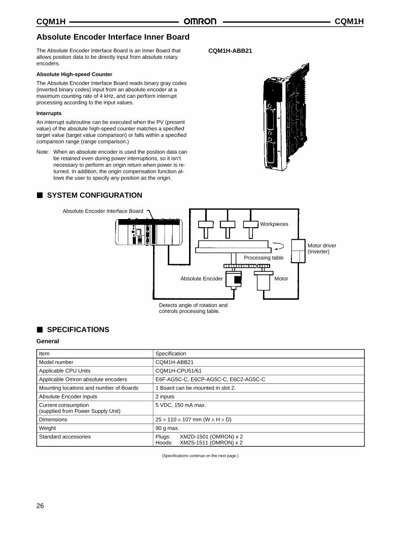
Absolute Encoder Interface Inner Board
The Absolute Encoder Interface Board is an Inner Board thatallows position data to be directly input from absolute rotaryencoders.
Absolute High-speed Counter
The Absolute Encoder Interface Board reads binary gray codes(inverted binary codes) input from an absolute encoder at amaximum counting rate of 4 kHz, and can perform interruptprocessing according to the input values.
Interrupts
An interrupt subroutine can be executed when the PV (presentvalue) of the absolute high-speed counter matches a specifiedtarget value (target value comparison) or falls within a specifiedcomparison range (range comparison.)
Note: When an absolute encoder is used the position data canbe retained even during power interruptions, so it isn’tnecessary to perform an origin return when power is re-turned. In addition, the origin compensation function al-lows the user to specify any position as the origin.
CQM1H-ABB21
SYSTEM CONFIGURATION
Absolute Encoder Interface Board
Workpieces
Motor driver(Inverter)
Processing table
Absolute Encoder Motor
Detects angle of rotation andcontrols processing table.
SPECIFICATIONS
General
Item Specification
Model number CQM1H-ABB21
Applicable CPU Units CQM1H-CPU51/61
Applicable Omron absolute encoders E6F-AG5C-C, E6CP-AG5C-C, E6C2-AG5C-C
Mounting locations and number of Boards 1 Board can be mounted in slot 2.
Absolute Encoder inputs 2 inputs
Current consumption (supplied from Power Supply Unit)
5 VDC, 150 mA max.
Dimensions 25 × 110 × 107 mm (W × H × D)
Weight 90 g max.
Standard accessories Plugs: XM2D-1501 (OMRON) x 2Hoods: XM2S-1511 (OMRON) x 2
(Specifications continue on the next page.)
CQM1H CQM1H
27
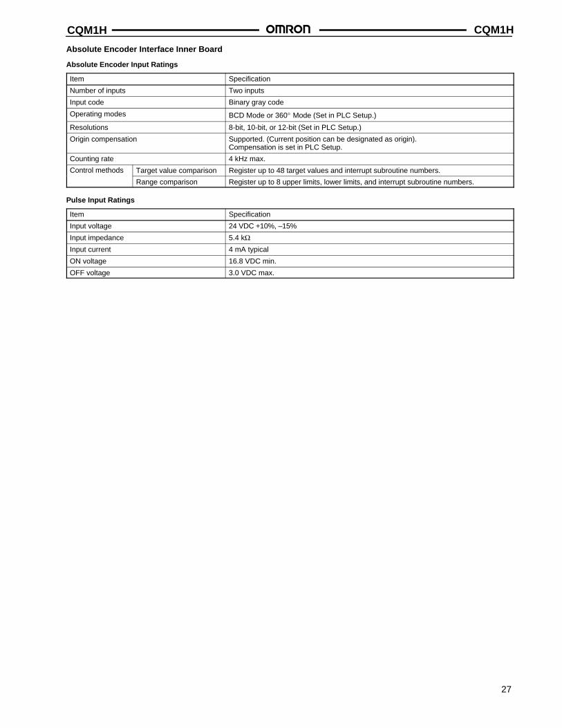
Absolute Encoder Interface Inner Board
Absolute Encoder Input Ratings
Item Specification
Number of inputs Two inputs
Input code Binary gray code
Operating modes BCD Mode or 360° Mode (Set in PLC Setup.)
Resolutions 8-bit, 10-bit, or 12-bit (Set in PLC Setup.)
Origin compensation Supported. (Current position can be designated as origin).Compensation is set in PLC Setup.
Counting rate 4 kHz max.
Control methods Target value comparison Register up to 48 target values and interrupt subroutine numbers.
Range comparison Register up to 8 upper limits, lower limits, and interrupt subroutine numbers.
Pulse Input Ratings
Item Specification
Input voltage 24 VDC +10%, –15%
Input impedance 5.4 kΩInput current 4 mA typical
ON voltage 16.8 VDC min.
OFF voltage 3.0 VDC max.
CQM1HCQM1H
28
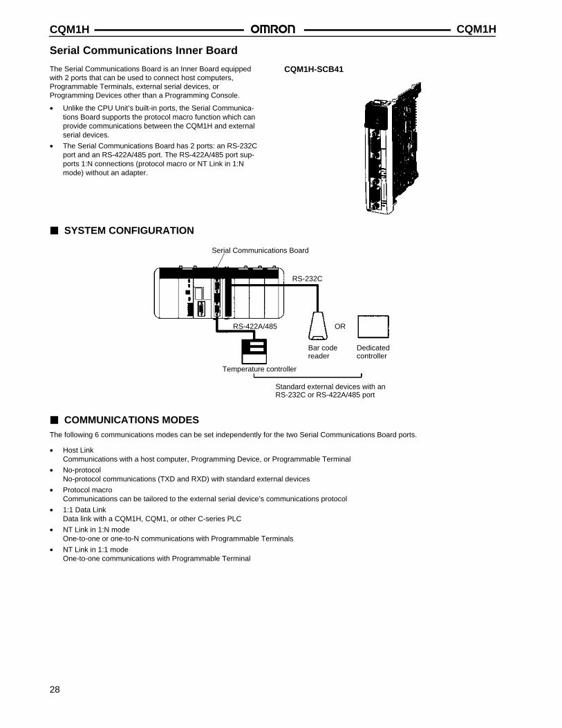
Serial Communications Inner Board
The Serial Communications Board is an Inner Board equippedwith 2 ports that can be used to connect host computers,Programmable Terminals, external serial devices, orProgramming Devices other than a Programming Console.
• Unlike the CPU Unit’s built-in ports, the Serial Communica-tions Board supports the protocol macro function which canprovide communications between the CQM1H and externalserial devices.
• The Serial Communications Board has 2 ports: an RS-232Cport and an RS-422A/485 port. The RS-422A/485 port sup-ports 1:N connections (protocol macro or NT Link in 1:Nmode) without an adapter.
CQM1H-SCB41
SYSTEM CONFIGURATION
Temperature controller
Serial Communications Board
RS-232C
RS-422A/485
Bar codereader
OR
Dedicatedcontroller
Standard external devices with anRS-232C or RS-422A/485 port
COMMUNICATIONS MODESThe following 6 communications modes can be set independently for the two Serial Communications Board ports.
• Host LinkCommunications with a host computer, Programming Device, or Programmable Terminal
• No-protocolNo-protocol communications (TXD and RXD) with standard external devices
• Protocol macroCommunications can be tailored to the external serial device’s communications protocol
• 1:1 Data LinkData link with a CQM1H, CQM1, or other C-series PLC
• NT Link in 1:N modeOne-to-one or one-to-N communications with Programmable Terminals
• NT Link in 1:1 modeOne-to-one communications with Programmable Terminal
CQM1H CQM1H
29
COMMUNICATIONS PORTS AND SERIAL COMMUNICATIONS MODES
Serial communications protocol CQM1H-SCB41 Serial communications board
RS-232C port (port 1) RS-422A/485 port (port 2)
Peripheral bus or Programming Console bus No No
Host Link (SYSMAC WAY) YES YES (See Note 1)
Protocol macro YES YES
No-protocol YES YES (See Note 1)
1:1 Data Link YES YES (See Note 1)
NT Link in 1:1 mode YES (See Note 2) YES (See Note 2)
NT Link in 1:N mode YES (See Note 2) YES (See Note 2)
Note: 1. The 4-wire method must be used if the RS-422A/485 port is used in Host Link, No-protocol, or 1:1 Data Link mode.2. A Programmable Terminal’s Programming Console function cannot be used.
SPECIFICATIONS
Item Specification
Model CQM1H-SCB41
Unit classification CQM1H-series Inner Board
Applicable CPU Units CQM1H-CPU61/51
Mounting locations and number of Boards 1 Board can be mounted in slot 1.
Serial Communications ports Port 1 RS-232C: 19.2 kbps max., 15 m max.
Port 2 RS-422A/485: 19.2 kbps max., 500 m max.
Protocols Port 1 Each port can be set independently to Host Link, No-protocol, Protocol macro, 1:1
Port 2 Data Link, NT Link in 1:N mode, or NT Link in 1:1 mode.
Current consumption 200 mA max.
Dimensions 32 × 131 × 107 mm (W × H × D)
Weight 90 g max.
Standard accessories Plugs: XM2SA-0901 (OMRON) x 1Hoods: XM2SA-0911 (OMRON) x 1 (ESD)
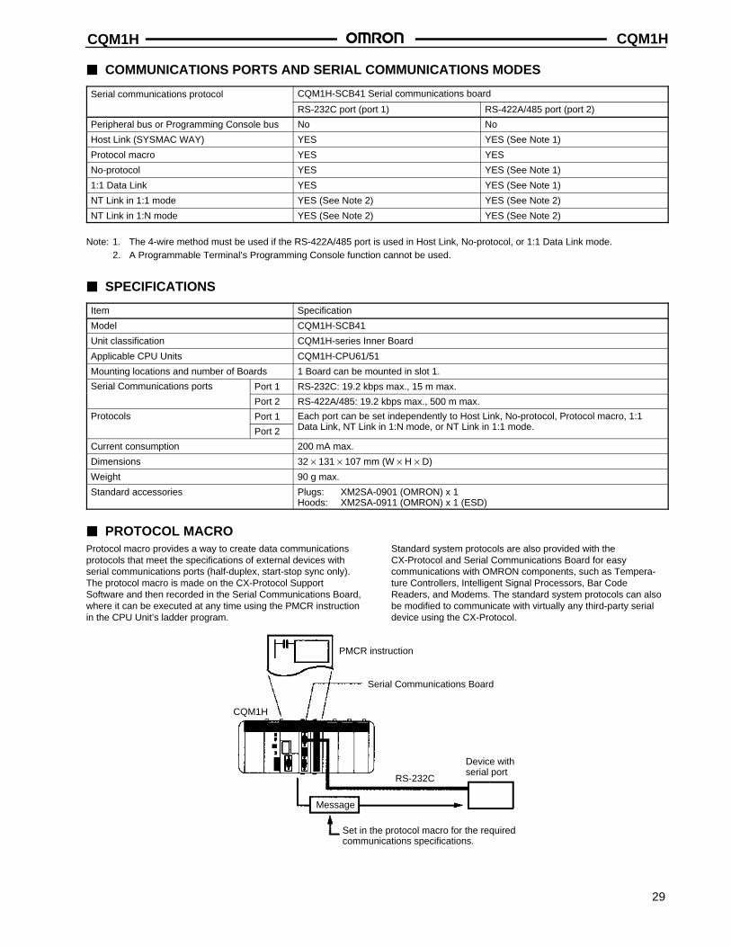
PROTOCOL MACROProtocol macro provides a way to create data communicationsprotocols that meet the specifications of external devices withserial communications ports (half-duplex, start-stop sync only).The protocol macro is made on the CX-Protocol SupportSoftware and then recorded in the Serial Communications Board,where it can be executed at any time using the PMCR instructionin the CPU Unit’s ladder program.
Standard system protocols are also provided with theCX-Protocol and Serial Communications Board for easycommunications with OMRON components, such as Tempera-ture Controllers, Intelligent Signal Processors, Bar CodeReaders, and Modems. The standard system protocols can alsobe modified to communicate with virtually any third-party serialdevice using the CX-Protocol.
PMCR instruction
CQM1H
Serial Communications Board
RS-232C
Message
Set in the protocol macro for the requiredcommunications specifications.
Device withserial port
CQM1HCQM1H
30
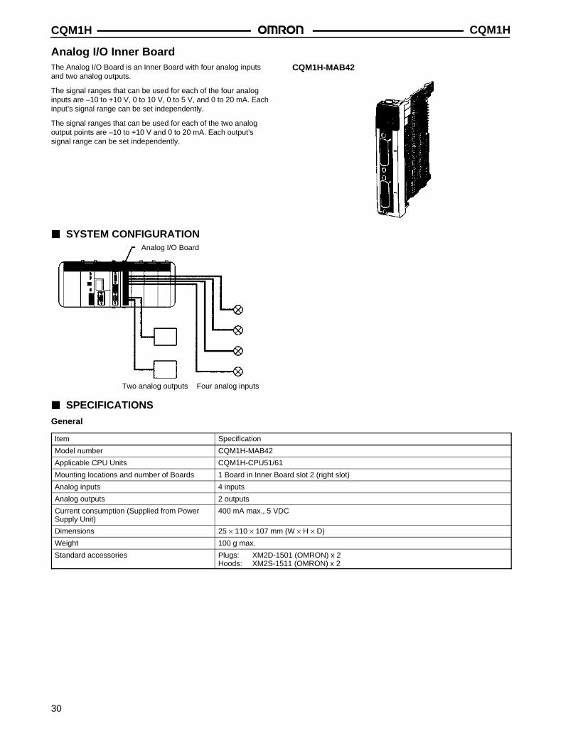
Analog I/O Inner BoardThe Analog I/O Board is an Inner Board with four analog inputsand two analog outputs.
The signal ranges that can be used for each of the four analoginputs are –10 to +10 V, 0 to 10 V, 0 to 5 V, and 0 to 20 mA. Eachinput’s signal range can be set independently.
The signal ranges that can be used for each of the two analogoutput points are –10 to +10 V and 0 to 20 mA. Each output’ssignal range can be set independently.
CQM1H-MAB42
SYSTEM CONFIGURATIONAnalog I/O Board
Four analog inputsTwo analog outputs
SPECIFICATIONS
General
Item Specification
Model number CQM1H-MAB42
Applicable CPU Units CQM1H-CPU51/61
Mounting locations and number of Boards 1 Board in Inner Board slot 2 (right slot)
Analog inputs 4 inputs
Analog outputs 2 outputs
Current consumption (Supplied from PowerSupply Unit)
400 mA max., 5 VDC
Dimensions 25 × 110 × 107 mm (W × H × D)
Weight 100 g max.
Standard accessories Plugs: XM2D-1501 (OMRON) x 2Hoods: XM2S-1511 (OMRON) x 2
CQM1H CQM1H
31
Analog I/O Inner Board
Analog Input Ratings
Item Specification
Input signals Voltage inputs Current inputs
Number of analog inputs 4 inputs
Input signal ranges (See Note 1) –10 to 10 V0 to 10 V0 to 5 V
0 to 20 mA
A/D conversion time (See Note 2) 1.7 ms max./point
Resolution 1/4,096
A/D conversion output data 12-bit binary data–10 to +10 V: F800 to 07FF Hex0 to 10 V, 0 to 5 V: 0000 to 0FFF Hex
12-bit binary data0 to 20 mA: 0000 to 0FFF Hex
External input impedance 1 MΩ typical 250 Ω typical
Absolute maximum rated input ±15 V ±30 mA
Overall precision (See Note 3) 23±2°C ±0.5% of FS
0 to 55°C ±1.0% of FS
Note: 1. Separate input signal ranges can be set for each input.2. The A/D conversion time is the time taken for an analog signal to be stored in memory as digital data. At least one cycle is re-
quired to transfer the data to the CPU Unit.3. The overall precision is the precision with respect to full scale.4. The CQM1H-MAB42 Analog I/O Board, unlike the CQM1-AD041, does not have a hardware average processing function. If
averaging of data is required, use the CPU Unit’s data averaging instruction (AVG).
Analog Output Ratings
Item Specification
Output signals Voltage outputs Current outputs
Number of analog outputs 2 outputs
Output signal ranges (See Note 1) –10 to 10 V 0 to 20 mA
D/A conversion time (See Note 2) 1.7 ms max./2 points
Resolution 1/4,096 1/2,048
Set output data 12-bit binary data–10 to +10 V: F800 to 07FF Hex
11-bit binary data0 to 20 mA: 0000 to 07FF Hex
Allowable external output load resistance 2 KΩ min. 350 Ω max.
Overall precision (See Note 3) 23±2°C ±0.5% of FS
0 to 55°C ±1.0% of FS
Note: 1. Separate output signal ranges can be set for each output.2. The D/A conversion time is the time taken for the output data set in memory to be converted to analog signals and output. At
least one cycle is required to transfer the data in the CPU Unit to the Analog I/O Board.3. The overall precision is the precision with respect to full scale.
CQM1HCQM1H
32
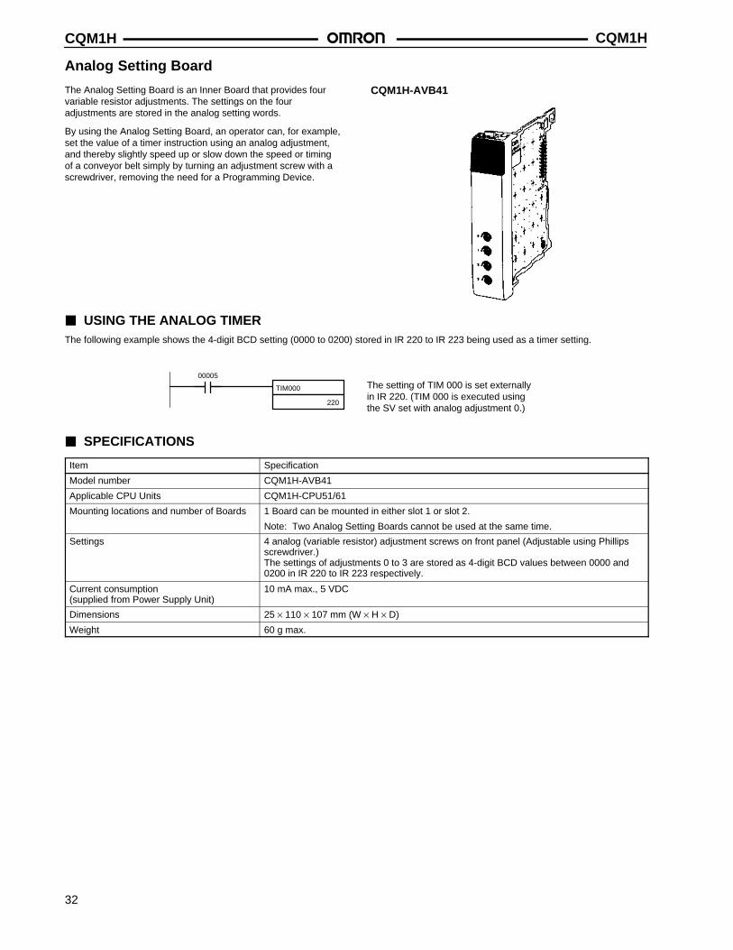
Analog Setting Board
The Analog Setting Board is an Inner Board that provides fourvariable resistor adjustments. The settings on the fouradjustments are stored in the analog setting words.
By using the Analog Setting Board, an operator can, for example,set the value of a timer instruction using an analog adjustment,and thereby slightly speed up or slow down the speed or timingof a conveyor belt simply by turning an adjustment screw with ascrewdriver, removing the need for a Programming Device.
CQM1H-AVB41
USING THE ANALOG TIMERThe following example shows the 4-digit BCD setting (0000 to 0200) stored in IR 220 to IR 223 being used as a timer setting.
TIM000
220
00005The setting of TIM 000 is set externallyin IR 220. (TIM 000 is executed usingthe SV set with analog adjustment 0.)
SPECIFICATIONS
Item Specification
Model number CQM1H-AVB41
Applicable CPU Units CQM1H-CPU51/61
Mounting locations and number of Boards 1 Board can be mounted in either slot 1 or slot 2.
Note: Two Analog Setting Boards cannot be used at the same time.
Settings 4 analog (variable resistor) adjustment screws on front panel (Adjustable using Phillipsscrewdriver.)The settings of adjustments 0 to 3 are stored as 4-digit BCD values between 0000 and0200 in IR 220 to IR 223 respectively.
Current consumption (supplied from Power Supply Unit)
10 mA max., 5 VDC
Dimensions 25 × 110 × 107 mm (W × H × D)
Weight 60 g max.
CQM1H CQM1H
33
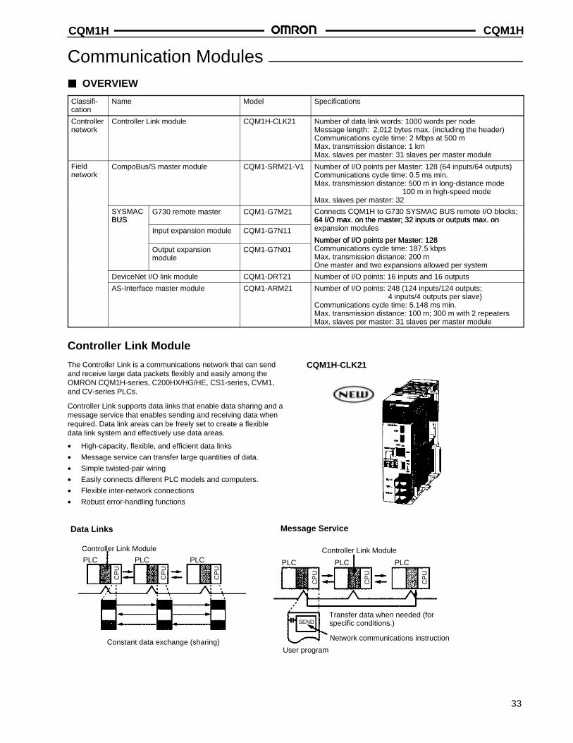
Communication Modules OVERVIEW
Classifi-cation
Name Model Specifications
Controllernetwork
Controller Link module CQM1H-CLK21 Number of data link words: 1000 words per nodeMessage length: 2,012 bytes max. (including the header)Communications cycle time: 2 Mbps at 500 mMax. transmission distance: 1 kmMax. slaves per master: 31 slaves per master module
Field network
CompoBus/S master module CQM1-SRM21-V1 Number of I/O points per Master: 128 (64 inputs/64 outputs)Communications cycle time: 0.5 ms min.Max. transmission distance: 500 m in long-distance mode
100 m in high-speed modeMax. slaves per master: 32
SYSMACBUS
G730 remote master CQM1-G7M21 Connects CQM1H to G730 SYSMAC BUS remote I/O blocks;64 I/O max. on the master; 32 inputs or outputs max. on BUS
Input expansion module CQM1-G7N11
64 I/O max. on the master; 32 inputs or outputs max. on expansion modules
Number of I/O points per Master: 128Output expansion module
CQM1-G7N01Number of I/O points per Master: 128Communications cycle time: 187.5 kbpsMax. transmission distance: 200 mOne master and two expansions allowed per system
DeviceNet I/O link module CQM1-DRT21 Number of I/O points: 16 inputs and 16 outputs
AS-Interface master module CQM1-ARM21 Number of I/O points: 248 (124 inputs/124 outputs; 4 inputs/4 outputs per slave)
Communications cycle time: 5.148 ms min.Max. transmission distance: 100 m; 300 m with 2 repeatersMax. slaves per master: 31 slaves per master module
Controller Link Module
The Controller Link is a communications network that can sendand receive large data packets flexibly and easily among theOMRON CQM1H-series, C200HX/HG/HE, CS1-series, CVM1,and CV-series PLCs.
Controller Link supports data links that enable data sharing and amessage service that enables sending and receiving data whenrequired. Data link areas can be freely set to create a flexibledata link system and effectively use data areas.
• High-capacity, flexible, and efficient data links
• Message service can transfer large quantities of data.
• Simple twisted-pair wiring
• Easily connects different PLC models and computers.
• Flexible inter-network connections
• Robust error-handling functions
CQM1H-CLK21
Data Links Message Service
Controller Link Module
Constant data exchange (sharing)
Controller Link Module
Transfer data when needed (forspecific conditions.)
Network communications instruction
User program
PLCPLC PLC PLCPLC PLC
SEND
CP
U
CP
U
CP
U
CP
U
CP
U
CP
U
CQM1HCQM1H
34
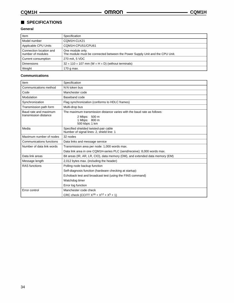
SPECIFICATIONS
General
Item Specification
Model number CQM1H-CLK21
Applicable CPU Units CQM1H-CPU51/CPU61
Connection location andnumber of modules
One module only.The module must be connected between the Power Supply Unit and the CPU Unit.
Current consumption 270 mA, 5 VDC
Dimensions 32 × 110 × 107 mm (W × H × D) (without terminals)
Weight 170 g max.
Communications
Item Specification
Communications method N:N token bus
Code Manchester code
Modulation Baseband code
Synchronization Flag synchronization (conforms to HDLC frames)
Transmission path form Multi-drop bus
Baud rate and maximumtransmission distance
The maximum transmission distance varies with the baud rate as follows:
2 Mbps: 500 m1 Mbps: 800 m500 kbps: 1 km
Media Specified shielded twisted-pair cableNumber of signal lines: 2, shield line: 1
Maximum number of nodes 32 nodes
Communications functions Data links and message service
Number of data link words Transmission area per node: 1,000 words max.
Data link area in one CQM1H-series PLC (send/receive): 8,000 words max.
Data link areas Bit areas (IR, AR, LR, CIO), data memory (DM), and extended data memory (EM)
Message length 2,012 bytes max. (including the header)
RAS functions Polling node backup function
Self-diagnosis function (hardware checking at startup)
Echoback test and broadcast test (using the FINS command)
Watchdog timer
Error log function
Error control Manchester code check
CRC check (CCITT X16 + X12 + X5 + 1)
CQM1H CQM1H
35
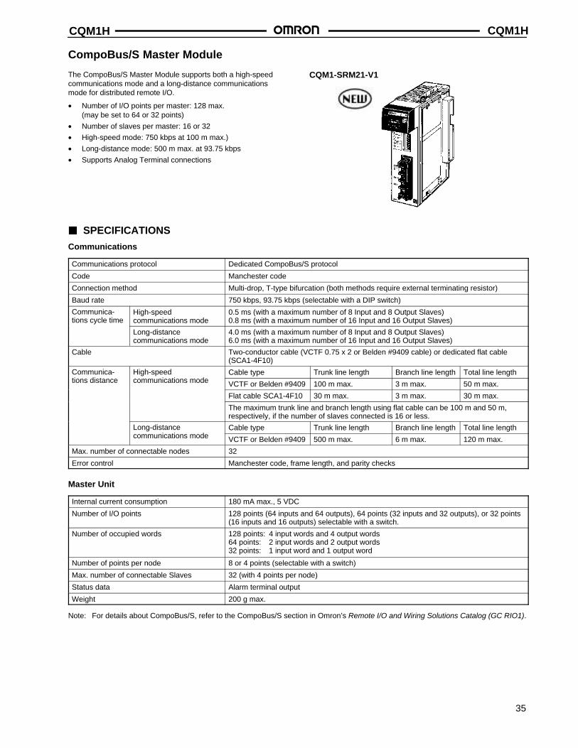
CompoBus/S Master Module
The CompoBus/S Master Module supports both a high-speedcommunications mode and a long-distance communicationsmode for distributed remote I/O.
• Number of I/O points per master: 128 max. (may be set to 64 or 32 points)
• Number of slaves per master: 16 or 32
• High-speed mode: 750 kbps at 100 m max.)
• Long-distance mode: 500 m max. at 93.75 kbps
• Supports Analog Terminal connections
CQM1-SRM21-V1
SPECIFICATIONS
Communications
Communications protocol Dedicated CompoBus/S protocol
Code Manchester code
Connection method Multi-drop, T-type bifurcation (both methods require external terminating resistor)
Baud rate 750 kbps, 93.75 kbps (selectable with a DIP switch)
Communica-tions cycle time
High-speed communications mode
0.5 ms (with a maximum number of 8 Input and 8 Output Slaves)0.8 ms (with a maximum number of 16 Input and 16 Output Slaves)
Long-distance communications mode
4.0 ms (with a maximum number of 8 Input and 8 Output Slaves)6.0 ms (with a maximum number of 16 Input and 16 Output Slaves)
Cable Two-conductor cable (VCTF 0.75 x 2 or Belden #9409 cable) or dedicated flat cable(SCA1-4F10)
Communica- High-speed Cable type Trunk line length Branch line length Total line lengthtions distance communications mode VCTF or Belden #9409 100 m max. 3 m max. 50 m max.
Flat cable SCA1-4F10 30 m max. 3 m max. 30 m max.
The maximum trunk line and branch length using flat cable can be 100 m and 50 m,respectively, if the number of slaves connected is 16 or less.
Long-distance Cable type Trunk line length Branch line length Total line lengthcommunications mode VCTF or Belden #9409 500 m max. 6 m max. 120 m max.
Max. number of connectable nodes 32
Error control Manchester code, frame length, and parity checks
Master Unit
Internal current consumption 180 mA max., 5 VDC
Number of I/O points 128 points (64 inputs and 64 outputs), 64 points (32 inputs and 32 outputs), or 32 points(16 inputs and 16 outputs) selectable with a switch.
Number of occupied words 128 points: 4 input words and 4 output words64 points: 2 input words and 2 output words32 points: 1 input word and 1 output word
Number of points per node 8 or 4 points (selectable with a switch)
Max. number of connectable Slaves 32 (with 4 points per node)
Status data Alarm terminal output
Weight 200 g max.
Note: For details about CompoBus/S, refer to the CompoBus/S section in Omron’s Remote I/O and Wiring Solutions Catalog (GC RIO1).
CQM1HCQM1H
36
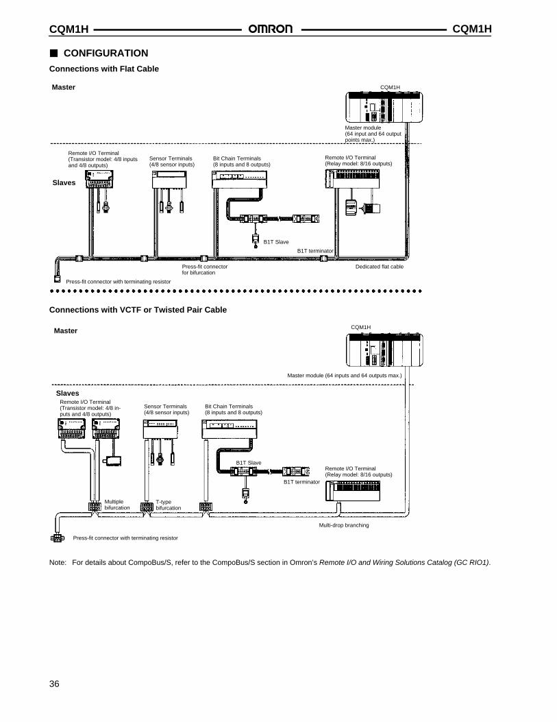
CONFIGURATION
Connections with Flat Cable
Master
Master module (64 input and 64 outputpoints max.)
Slaves
Remote I/O Terminal (Transistor model: 4/8 inputsand 4/8 outputs)
Sensor Terminals(4/8 sensor inputs)
Bit Chain Terminals(8 inputs and 8 outputs)
Remote I/O Terminal(Relay model: 8/16 outputs)
B1T Slave
B1T terminator
Press-fit connector for bifurcation
Dedicated flat cable
Press-fit connector with terminating resistor
CQM1H
Connections with VCTF or Twisted Pair Cable
Master
Master module (64 inputs and 64 outputs max.)
SlavesRemote I/O Terminal(Transistor model: 4/8 in-puts and 4/8 outputs)
Sensor Terminals (4/8 sensor inputs)
Bit Chain Terminals(8 inputs and 8 outputs)
Remote I/O Terminal (Relay model: 8/16 outputs)
B1T Slave
B1T terminator
Press-fit connector with terminating resistor
Multiple bifurcation
T-type bifurcation
Multi-drop branching
CQM1H
Note: For details about CompoBus/S, refer to the CompoBus/S section in Omron’s Remote I/O and Wiring Solutions Catalog (GC RIO1).
CQM1H CQM1H
37
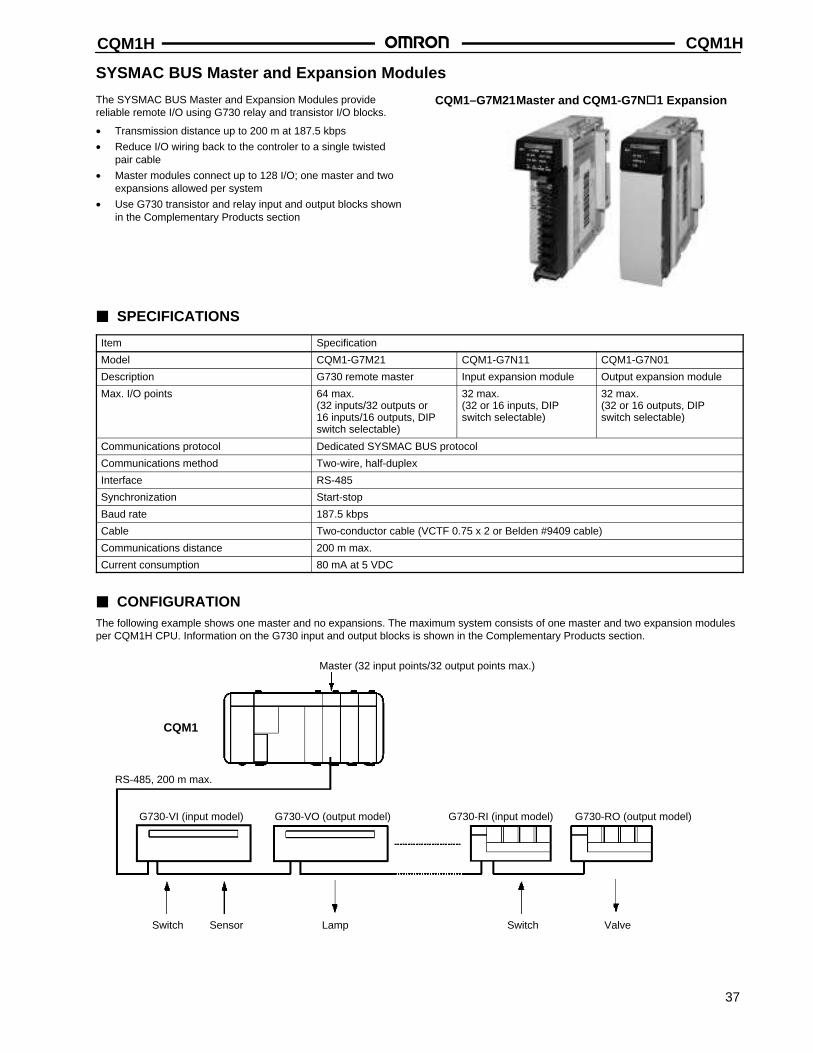
SYSMAC BUS Master and Expansion Modules
The SYSMAC BUS Master and Expansion Modules providereliable remote I/O using G730 relay and transistor I/O blocks.
• Transmission distance up to 200 m at 187.5 kbps
• Reduce I/O wiring back to the controler to a single twistedpair cable
• Master modules connect up to 128 I/O; one master and twoexpansions allowed per system
• Use G730 transistor and relay input and output blocks shownin the Complementary Products section
CQM1–G7M21 Master and CQM1-G7N1 Expansion
SPECIFICATIONS
Item Specification
Model CQM1-G7M21 CQM1-G7N11 CQM1-G7N01
Description G730 remote master Input expansion module Output expansion module
Max. I/O points 64 max.(32 inputs/32 outputs or 16 inputs/16 outputs, DIPswitch selectable)
32 max.(32 or 16 inputs, DIPswitch selectable)
32 max.(32 or 16 outputs, DIPswitch selectable)
Communications protocol Dedicated SYSMAC BUS protocol
Communications method Two-wire, half-duplex
Interface RS-485
Synchronization Start-stop
Baud rate 187.5 kbps
Cable Two-conductor cable (VCTF 0.75 x 2 or Belden #9409 cable)
Communications distance 200 m max.
Current consumption 80 mA at 5 VDC
CONFIGURATIONThe following example shows one master and no expansions. The maximum system consists of one master and two expansion modulesper CQM1H CPU. Information on the G730 input and output blocks is shown in the Complementary Products section.
Master (32 input points/32 output points max.)
RS-485, 200 m max.
G730-VI (input model) G730-VO (output model) G730-RI (input model) G730-RO (output model)
Switch Sensor Lamp ValveSwitch
CQM1
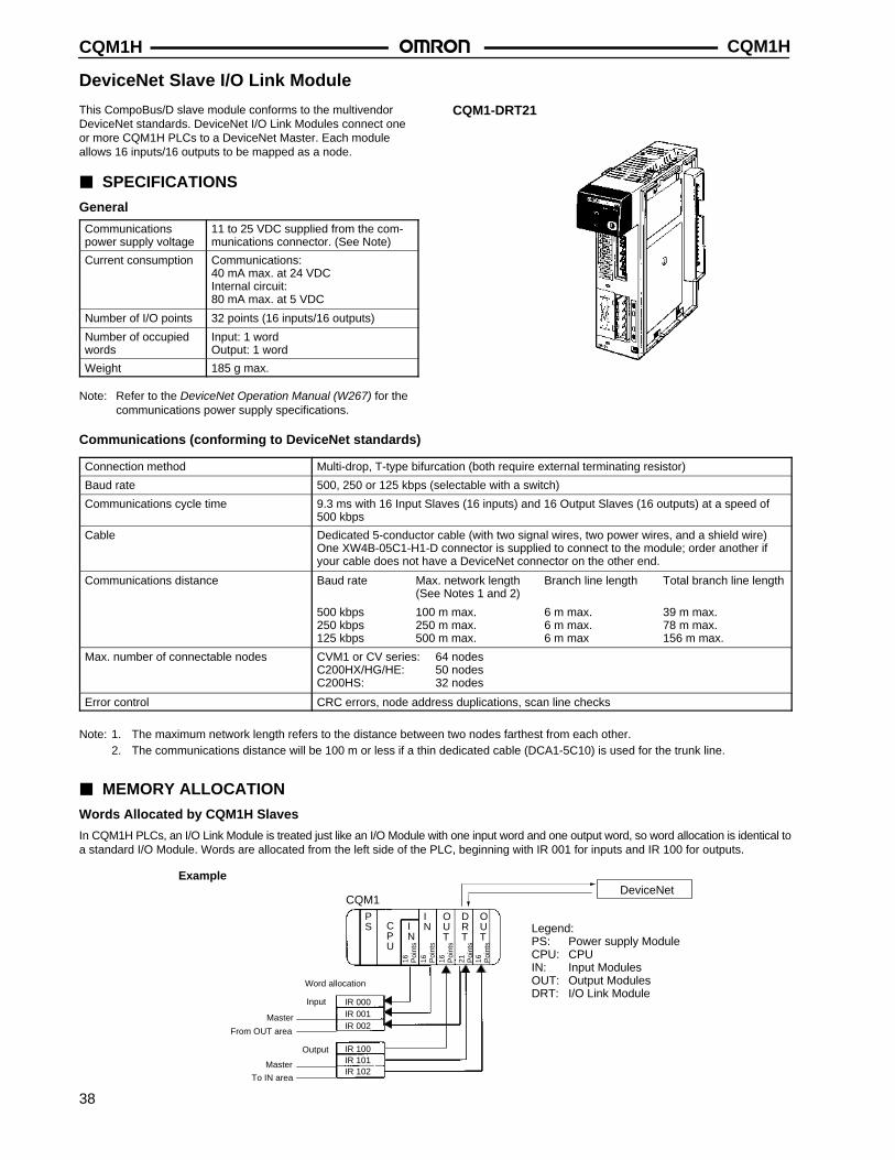
CQM1HCQM1H
38
DeviceNet Slave I/O Link Module
This CompoBus/D slave module conforms to the multivendorDeviceNet standards. DeviceNet I/O Link Modules connect oneor more CQM1H PLCs to a DeviceNet Master. Each moduleallows 16 inputs/16 outputs to be mapped as a node.
SPECIFICATIONS
General
Communicationspower supply voltage
11 to 25 VDC supplied from the com-munications connector. (See Note)
Current consumption Communications:40 mA max. at 24 VDCInternal circuit:80 mA max. at 5 VDC
Number of I/O points 32 points (16 inputs/16 outputs)
Number of occupiedwords
Input: 1 wordOutput: 1 word
Weight 185 g max.
Note: Refer to the DeviceNet Operation Manual (W267) for thecommunications power supply specifications.
CQM1-DRT21
Communications (conforming to DeviceNet standards)
Connection method Multi-drop, T-type bifurcation (both require external terminating resistor)
Baud rate 500, 250 or 125 kbps (selectable with a switch)
Communications cycle time 9.3 ms with 16 Input Slaves (16 inputs) and 16 Output Slaves (16 outputs) at a speed of500 kbps
Cable Dedicated 5-conductor cable (with two signal wires, two power wires, and a shield wire)One XW4B-05C1-H1-D connector is supplied to connect to the module; order another ifyour cable does not have a DeviceNet connector on the other end.
Communications distance Baud rate Max. network length Branch line length Total branch line length(See Notes 1 and 2)
500 kbps 100 m max. 6 m max. 39 m max.250 kbps 250 m max. 6 m max. 78 m max.125 kbps 500 m max. 6 m max 156 m max.
Max. number of connectable nodes CVM1 or CV series: 64 nodesC200HX/HG/HE: 50 nodesC200HS: 32 nodes
Error control CRC errors, node address duplications, scan line checks
Note: 1. The maximum network length refers to the distance between two nodes farthest from each other.2. The communications distance will be 100 m or less if a thin dedicated cable (DCA1-5C10) is used for the trunk line.
MEMORY ALLOCATION
Words Allocated by CQM1H Slaves
In CQM1H PLCs, an I/O Link Module is treated just like an I/O Module with one input word and one output word, so word allocation is identical toa standard I/O Module. Words are allocated from the left side of the PLC, beginning with IR 001 for inputs and IR 100 for outputs.
Word allocation
Input
16 Poi
nts
16 Poi
nts
16 Poi
nts
16 Poi
nts
Legend:PS: Power supply ModuleCPU: CPUIN: Input ModulesOUT: Output ModulesDRT: I/O Link Module
Example
CQM1
IR 000
IR 100
DeviceNet
IR 102IR 101
IR 002IR 001
21 Poi
nts
Master
From OUT area
Output
Master
To IN area
PS C
PU
INI
N
OUT
OUT
DRT
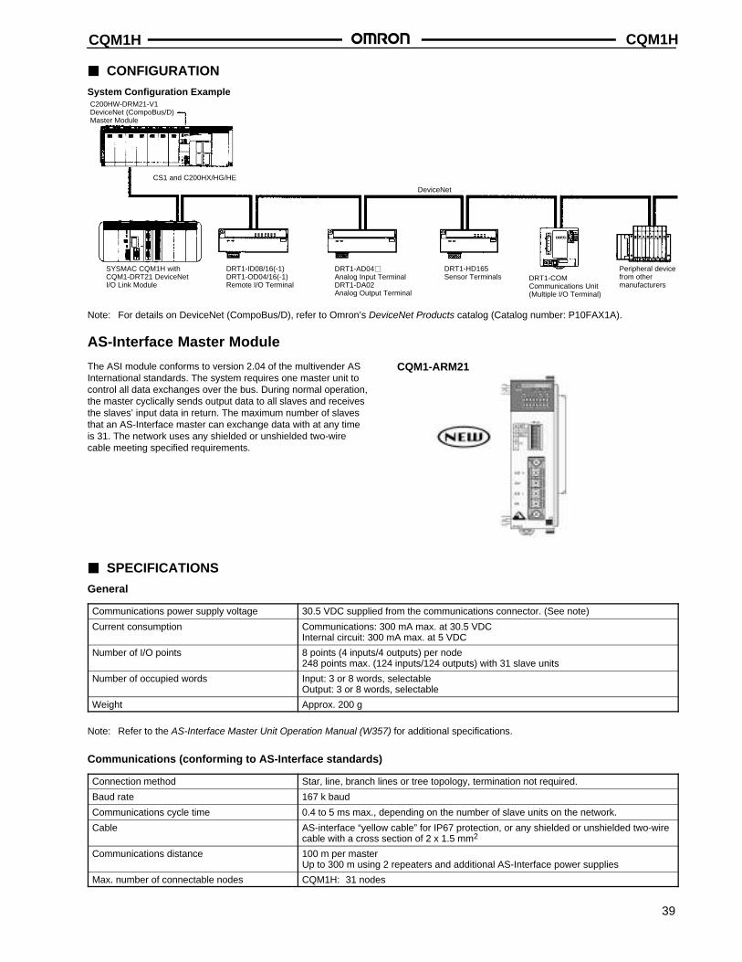
CQM1H CQM1H
39
CONFIGURATIONSystem Configuration Example
DRT1-ID08/16(-1)DRT1-OD04/16(-1)Remote I/O Terminal
DRT1-AD04Analog Input TerminalDRT1-DA02Analog Output Terminal
DRT1-HD165Sensor Terminals
Peripheral devicefrom other manufacturers
DeviceNet
DRT1-COMCommunications Unit (Multiple I/O Terminal)
C200HW-DRM21-V1DeviceNet (CompoBus/D)Master Module
CS1 and C200HX/HG/HE
SYSMAC CQM1H withCQM1-DRT21 DeviceNetI/O Link Module
Note: For details on DeviceNet (CompoBus/D), refer to Omron’s DeviceNet Products catalog (Catalog number: P10FAX1A).
AS-Interface Master Module
The ASI module conforms to version 2.04 of the multivender ASInternational standards. The system requires one master unit tocontrol all data exchanges over the bus. During normal operation,the master cyclically sends output data to all slaves and receivesthe slaves’ input data in return. The maximum number of slavesthat an AS-Interface master can exchange data with at any timeis 31. The network uses any shielded or unshielded two-wirecable meeting specified requirements.
CQM1-ARM21
SPECIFICATIONS
General
Communications power supply voltage 30.5 VDC supplied from the communications connector. (See note)
Current consumption Communications: 300 mA max. at 30.5 VDCInternal circuit: 300 mA max. at 5 VDC
Number of I/O points 8 points (4 inputs/4 outputs) per node248 points max. (124 inputs/124 outputs) with 31 slave units
Number of occupied words Input: 3 or 8 words, selectableOutput: 3 or 8 words, selectable
Weight Approx. 200 g
Note: Refer to the AS-Interface Master Unit Operation Manual (W357) for additional specifications.
Communications (conforming to AS-Interface standards)
Connection method Star, line, branch lines or tree topology, termination not required.
Baud rate 167 k baud
Communications cycle time 0.4 to 5 ms max., depending on the number of slave units on the network.
Cable AS-interface “yellow cable” for IP67 protection, or any shielded or unshielded two-wirecable with a cross section of 2 x 1.5 mm2
Communications distance 100 m per masterUp to 300 m using 2 repeaters and additional AS-Interface power supplies
Max. number of connectable nodes CQM1H: 31 nodes
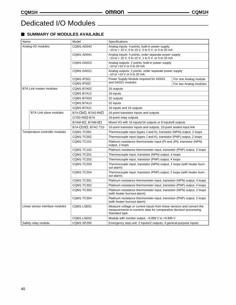
CQM1HCQM1H
40
Dedicated I/O Modules SUMMARY OF MODULES AVAILABLE
Name Model Specifications
Analog I/O modules CQM1-AD042 Analog inputs: 4 points, built-in power supply–10 to + 10 V, 0 to 10 V, 0 to 5 V, or 0 to 20 mA
CQM1-AD041 Analog inputs: 4 points, order separate power supply–10 to + 10 V, 0 to 10 V, 1 to 5 V, or 0 to 20 mA
CQM1-DA022 Analog outputs: 2 points, built-in power supply–10 to +10 V or 0 to 20 mA
CQM1-DA021 Analog outputs: 2 points, order separate power supply–10 to +10 V or 0 to 20 mA
CQM1-IPS01 Power Supply Module required for AD041 For one Analog moduleCQM1-IPS02 and DA021 modules For two Analog modules
B7A Link master modules CQM1-B7A02 16 outputs
CQM1-B7A12 16 inputs
CQM1-B7A03 32 outputs
CQM1-B7A13 32 inputs
CQM1-B7A21 16 inputs and 16 outputs
B7A Link slave modules B7A-6, B7AS-R6 16-point transistor inputs and outputs
G70D-R6-B7A 16-point relay outputs
B7AM-6, B7AM-8 Mixed I/O with 16 inputs/16 outputs or 8 inputs/8 outputs
B7A-10, B7AC-T10 10-point transistor inputs and outputs, 10-point sealed input link
Temperature controller modules CQM1-TC001 Thermocouple input (types J and K), transistor (NPN) output, 2 loops
CQM1-TC002 Thermocouple input (types J and K), transistor (PNP) output, 2 loops
CQM1-TC101 Platinum resistance thermometer input (Pt and JPt), transistor (NPN)output, 2 loops
CQM1-TC102 Platinum resistance thermometer input, transistor (PNP) output, 2 loops
CQM1-TC201 Thermocouple input, transistor (NPN) output, 4 loops
CQM1-TC202 Thermocouple input, transistor (PNP) output, 4 loops
CQM1-TC203 Thermocouple input, transistor (NPN) output, 2 loops (with heater burn-out alarm)
CQM1-TC204 Thermocouple input, transistor (PNP) output, 2 loops (with heater burn-out alarm)
CQM1-TC301 Platinum resistance thermometer input, transistor (NPN) output, 4 loops
CQM1-TC302 Platinum resistance thermometer input, transistor (PNP) output, 4 loops
CQM1-TC303 Platinum resistance thermometer input, transistor (NPN) output, 2 loops(with heater burnout alarm)
CQM1-TC304 Platinum resistance thermometer input, transistor (PNP) output, 2 loops(with heater burnout alarm)
Linear sensor interface modules CQM1-LSE01 Measure voltage or current inputs from linear sensors and convert themeasurements to numeric data for comparative decision processing.Standard type.
CQM1-LSE02 Module with monitor output: –9.999 V to +9.999 V
Safety relay module CQM1-SF200 Emergency stop unit: 2 inputs/2 outputs, 4 general-purpose inputs
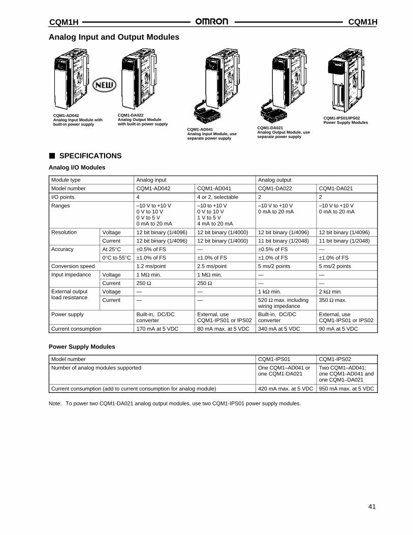
CQM1H CQM1H
41
Analog Input and Output Modules
CQM1-AD041Analog Input Module, useseparate power supply
CQM1-DA021Analog Output Module, useseparate power supply
CQM1-IPS01/IPS02Power Supply Modules
CQM1-AD042Analog Input Module withbuilt-in power supply
CQM1-DA022Analog Output Modulewith built-in power supply
SPECIFICATIONS
Analog I/O Modules
Module type Analog input Analog output
Model number CQM1-AD042 CQM1-AD041 CQM1-DA022 CQM1-DA021
I/O points 4 4 or 2, selectable 2 2
Ranges –10 V to +10 V0 V to 10 V0 V to 5 V0 mA to 20 mA
–10 to +10 V0 V to 10 V1 V to 5 V4 mA to 20 mA
–10 V to +10 V0 mA to 20 mA
–10 V to +10 V0 mA to 20 mA
Resolution Voltage 12 bit binary (1/4096) 12 bit binary (1/4000) 12 bit binary (1/4096) 12 bit binary (1/4096)
Current 12 bit binary (1/4096) 12 bit binary (1/4000) 11 bit binary (1/2048) 11 bit binary (1/2048)
Accuracy At 25°C ±0.5% of FS — ±0.5% of FS —
0°C to 55°C ±1.0% of FS ±1.0% of FS ±1.0% of FS ±1.0% of FS
Conversion speed 1.2 ms/point 2.5 ms/point 5 ms/2 points 5 ms/2 points
Input impedance Voltage 1 MΩ min. 1 MΩ min. — —
Current 250 Ω 250 Ω — —
External output Voltage — — 1 kΩ min. 2 kΩ min.load resistance Current — — 520 Ω max. including
wiring impedance350 Ω max.
Power supply Built-in, DC/DC converter
External, useCQM1-IPS01 or IPS02
Built-in, DC/DC converter
External, useCQM1-IPS01 or IPS02
Current consumption 170 mA at 5 VDC 80 mA max. at 5 VDC 340 mA at 5 VDC 90 mA at 5 VDC
Power Supply Modules
Model number CQM1-IPS01 CQM1-IPS02
Number of analog modules supported One CQM1–AD041 orone CQM1-DA021
Two CQM1–AD041;one CQM1-AD041 andone CQM1–DA021
Current consumption (add to current consumption for analog module) 420 mA max. at 5 VDC 950 mA max. at 5 VDC
Note: To power two CQM1-DA021 analog output modules, use two CQM1-IPS01 power supply modules.
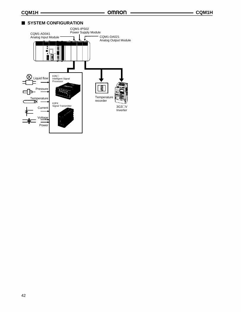
CQM1HCQM1H
42
SYSTEM CONFIGURATION
Liquid flow
Pressure
Temperature
Current
Voltage
K3N
Intelligent SignalProcessor
K3FKSignal Transmitter
CQM1-AD041Analog Input Module
CQM1-IPS02Power Supply Module
CQM1-DA021Analog Output Module
Temperaturerecorder
3G3VInverter
Power
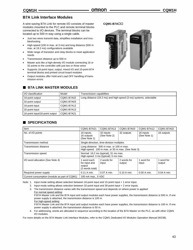
CQM1H CQM1H
43
B7A Link Interface Modules
A wire-saving B7A Link for remote I/O consists of mastermodules mounted to the PLC and remote terminal blocksconnected to I/O devices. The terminal blocks can belocated up to 500 m way using a single cable.
• Just two wires transmit data, simplifies installation and trou-bleshooting
• High-speed (100 m max. at 3 ms) and long distance (500 mmax. at 19.2 ms) configurations available
• Wide range of transistor and relay blocks to meet applicationneeds
• Transmission distance up to 500 m
• Master acts like a high-density I/O module connecting 16 or32 points to the controller with just two or three wires
• Supports 16-point input, output, mixed I/O and 10-point B7Aterminal blocks and printed circuit board modules
• Output modules offer Hold and Load OFF handling of trans-mission errors
CQM1-B7A
B7A LINK MASTER MODULES
I/O classification Model Transmission capabilities
16-point output CQM1-B7A02 Long distance (19.2 ms) and high-speed (3 ms) systems, selectable
32-point output CQM1-B7A03
16-point input CQM1-B7A12
32-point input CQM1-B7A13
16-point input/16-point output CQM1-B7A21
SPECIFICATIONS
Item CQM1-B7A21 CQM1-B7A13 CQM1-B7A03 CQM1-B7A12 CQM1-B7A02
No. of I/O points 16 inputs, 16 outputs (See Note 1)
32 inputs(See Note 2)
32 outputs 16 inputs(See Note 1)
16 outputs
Transmission method Single-direction, time-division multiplex
Transmission distance Long distance: 500 m max. or 100 m max.High-speed: 100 m max. or 50 m max. (See Note 3)
Transmission speed Normal: 19.2 ms (typical); 31 ms max.High-speed: 3 ms (typical); 5 ms max.
I/O word allocation (See Note 4) 1 word eachfor input andoutput (2 words total)
2 words forinput
2 words foroutput
1 word forinput
1 word for output
Required power supply 0.11 A min. 0.07 A min. 0.10 A min. 0.05 A min. 0.04 A min.
Current consumption (module as part of CQM1) 100 mA max., 5 VDC
Note: 1. Input mode setting allows selection between 16-point input and 15-point input + 1 error input.2. Input mode setting allows selection between 32-point input and 30-point input + 2 error inputs.3. The transmission distance varies with the transmission speed and depends on where power is applied:
For normal speed setting:If B7A Master Link and the B7A input and output modules each have power supplies, the transmission distance is 500 m. If onepower supply is attached, the transmission distance is 100 m.For high-speed setting:If B7A Master Link and the B7A input and output modules each have power supplies, the transmission distance is 100 m. If onepower supply is attached, the transmission distance is 50 m.
4. For addressing, words are allocated in sequence according to the location of the B7A Master on the PLC, as with other CQM1I/O modules.
For more details on the B7A Master Link Interface Modules, refer to the CQM1 Dedicated I/O Modules Operation Manual (W238).
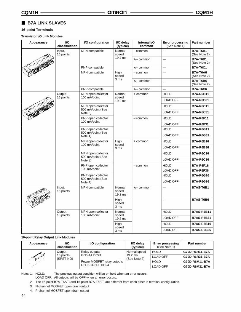
CQM1HCQM1H
44
B7A LINK SLAVES
16-point Terminals
Transistor I/O Link Modules
Appearance I/Oclassification
I/O configuration I/O delay(typical)
Internal I/Ocommon
Error processing(See Note 1)
Part number
Input,16 points
NPN compatible Normalspeed
– common — B7A-T6A1(See Note 2)
19.2 ms +/– common — B7A-T6B1(See Note 2)
PNP compatible +/– common — B7A-T6C1
NPN compatible Highspeed
– common — B7A-T6A6(See Note 2)
3 ms +/– common — B7A-T6B6(See Note 2)
PNP compatible +/– common — B7A-T6C6
Output, NPN open collector Normal + common HOLD B7A-R6B1116 points 100 mA/point speed
19.2 ms LOAD OFF B7A-R6B31
NPN open collector HOLD B7A-R6C11500 mA/point (SeeNote 3) LOAD OFF B7A-R6C31
PNP open collector – common HOLD B7A-R6F11100 mA/point
LOAD OFF B7A-R6F31
PNP open collector HOLD B7A-R6G11500 mA/point (SeeNote 4) LOAD OFF B7A-R6G31
NPN open collector High + common HOLD B7A-R6B16100 mA/point speed
3 ms LOAD OFF B7A-R6B36
NPN open collector HOLD B7A-R6C16500 mA/point (SeeNote 3) LOAD OFF B7A-R6C36
PNP open collector – common HOLD B7A-R6F16100 mA/point LOAD OFF B7A-R6F36
PNP open collector HOLD B7A-R6G16500 mA/point (SeeNote 4) LOAD OFF B7A-R6G36
Input.16 points
NPN compatible Normalspeed19.2 ms
+/– common — B7AS-T6B1
Highspeed3 ms
— B7AS-T6B6
Output, NPN open collector Normal HOLD B7AS-R6B1116 points 100 mA/point speed
19.2 ms LOAD OFF B7AS-R6B31
High HOLD B7AS-R6B16speed3 ms LOAD OFF B7AS-R6B36
16-point Relay Output Link Modules
Appearance I/Oclassification
I/O configuration I/O delay(typical)
Error processing(See Note 1)
Part number
Output, Relay outputs Normal speed HOLD G70D-R6R11-B7A16 points G6D-1A DC24 19.2 ms LOAD OFF G70D-R6R31-B7A(SPST-NO)
Power MOSFET relay outputs(See Note 2)
HOLD G70D-R6M11-B7AG3DZ-2R6PL DC24 LOAD OFF G70D-R6M31-B7A
Note: 1. HOLD: The previous output condition will be on hold when an error occurs.LOAD OFF: All outputs will be OFF when an error occurs.
2. The 16-point B7A-T6A and 16-point B7A-T6B are different from each other in terminal configuration.3. N-channel MOSFET open drain output4. P-channel MOSFET open drain output
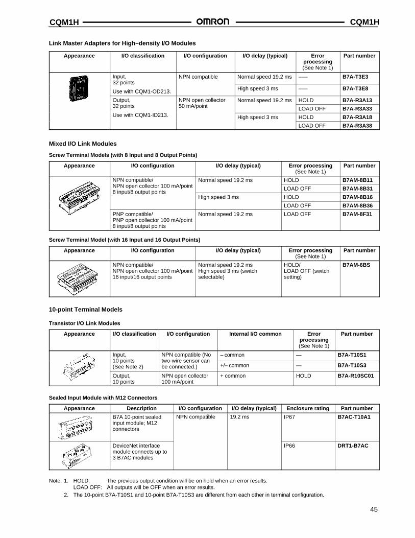
CQM1H CQM1H
45
Link Master Adapters for High–density I/O Modules
Appearance I/O classification I/O configuration I/O delay (typical) Errorprocessing(See Note 1)
Part number
Input, NPN compatible Normal speed 19.2 ms ––– B7A-T3E332 points
Use with CQM1-OD213. High speed 3 ms ––– B7A-T3E8
Output, NPN open collector Normal speed 19.2 ms HOLD B7A-R3A1332 points 50 mA/point LOAD OFF B7A-R3A33Use with CQM1-ID213. High speed 3 ms HOLD B7A-R3A18
LOAD OFF B7A-R3A38
Mixed I/O Link Modules
Screw Terminal Models (with 8 Input and 8 Output Points)
Appearance I/O configuration I/O delay (typical) Error processing(See Note 1)
Part number
NPN compatible/ Normal speed 19.2 ms HOLD B7AM-8B11NPN open collector 100 mA/point LOAD OFF B7AM-8B318 input/8 output points
High speed 3 ms HOLD B7AM-8B16
LOAD OFF B7AM-8B36
PNP compatible/PNP open collector 100 mA/point8 input/8 output points
Normal speed 19.2 ms LOAD OFF B7AM-8F31
Screw Terminal Model (with 16 Input and 16 Output Points)
Appearance I/O configuration I/O delay (typical) Error processing(See Note 1)
Part number
NPN compatible/NPN open collector 100 mA/point16 input/16 output points
Normal speed 19.2 msHigh speed 3 ms (switchselectable)
HOLD/LOAD OFF (switchsetting)
B7AM-6BS
10-point Terminal Models
Transistor I/O Link Modules
Appearance I/O classification I/O configuration Internal I/O common Errorprocessing(See Note 1)
Part number
Input, NPN compatible (No – common — B7A-T10S110 points(See Note 2)
two-wire sensor canbe connected.) +/– common — B7A-T10S3
Output,10 points
NPN open collector100 mA/point
+ common HOLD B7A-R10SC01
Sealed Input Module with M12 Connectors
Appearance Description I/O configuration I/O delay (typical) Enclosure rating Part number
B7A 10-point sealedinput module; M12connectors
NPN compatible 19.2 ms IP67 B7AC-T10A1
DeviceNet interfacemodule connects up to3 B7AC modules
IP66 DRT1-B7AC
Note: 1. HOLD: The previous output condition will be on hold when an error results.LOAD OFF: All outputs will be OFF when an error results.
2. The 10-point B7A-T10S1 and 10-point B7A-T10S3 are different from each other in terminal configuration.
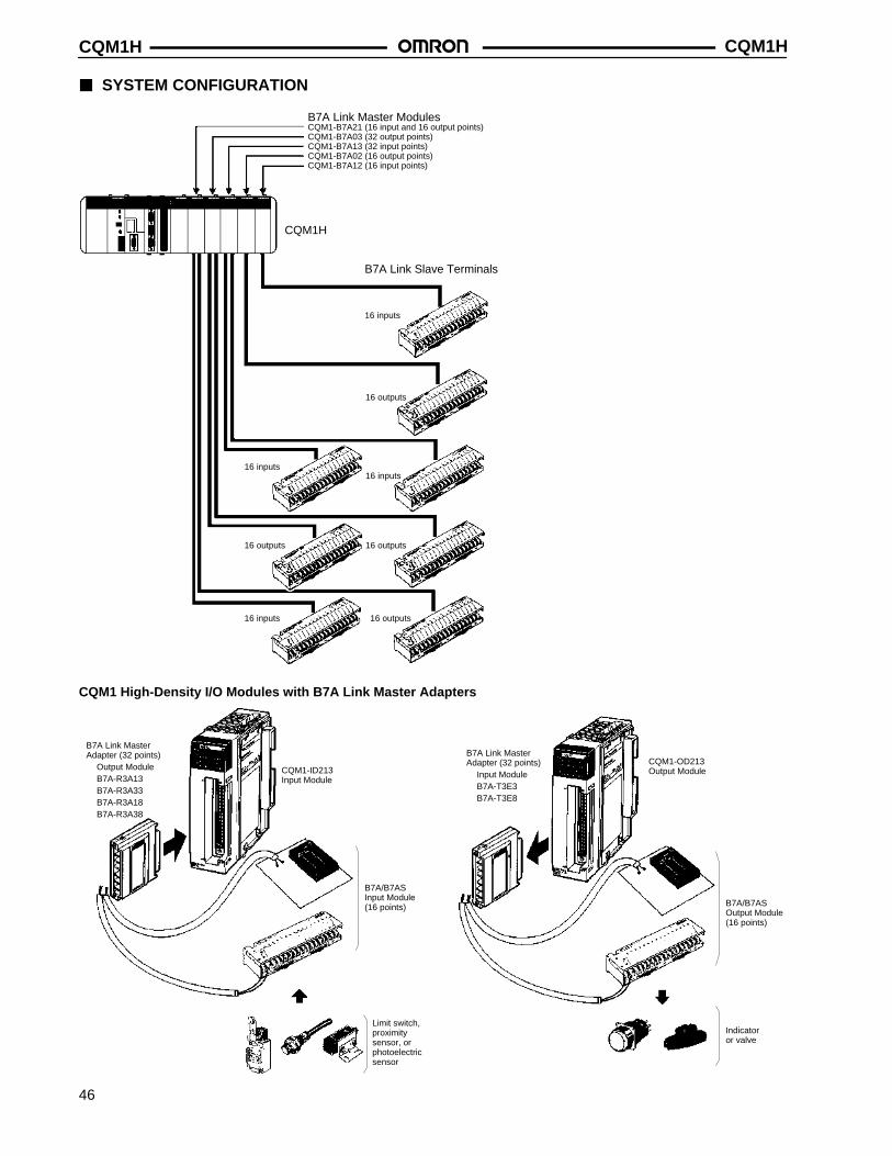
CQM1HCQM1H
46
SYSTEM CONFIGURATION
16 outputs
16 outputs
16 inputs
16 outputs
CQM1-B7A21 (16 input and 16 output points)CQM1-B7A03 (32 output points)CQM1-B7A13 (32 input points)CQM1-B7A02 (16 output points)CQM1-B7A12 (16 input points)
CQM1H
B7A Link Slave Terminals
16 inputs
16 inputs
16 outputs
16 inputs
B7A Link Master Modules
CQM1 High-Density I/O Modules with B7A Link Master Adapters
B7A Link MasterAdapter (32 points)
Output ModuleB7A-R3A13B7A-R3A33B7A-R3A18B7A-R3A38
CQM1-ID213Input Module
B7A/B7AS Input Module(16 points)
Limit switch,proximitysensor, orphotoelectricsensor
B7A Link MasterAdapter (32 points)
Input ModuleB7A-T3E3B7A-T3E8
CQM1-OD213Output Module
B7A/B7ASOutput Module(16 points)
Indicatoror valve
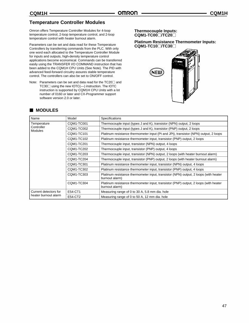
CQM1H CQM1H
47
Temperature Controller Modules
Omron offers Temperature Controller Modules for 4-looptemperature control, 2-loop temperature control, and 2-looptemperature control with heater burnout alarm.
Parameters can be set and data read for these TemperatureControllers by transferring commands from the PLC. With onlyone word each allocated to the Temperature Controller Modulefor inputs and outputs, high-density temperature controlapplications become economical. Commands can be transferredeasily using the TRANSFER I/O COMMAND instruction that hasbeen added to the CQM1H CPU Units (See Note). The PID withadvanced feed-forward circuitry assures stable temperaturecontrol. The controllers can also be set to ON/OFF control.
Note: Parameters can be set and data read for the TC20 andTC30 using the new IOTC(––) instruction. The IOTCinstruction is supported by CQM1H CPU Units with a lotnumber of 0160 or later and CX-Programmer supportsoftware version 2.0 or later.
Thermocouple Inputs: CQM1-TC00/TC20
Platinum Resistance Thermometer Inputs:CQM1-TC10/TC30
MODULES
Name Model Specifications
Temperature CQM1-TC001 Thermocouple input (types J and K), transistor (NPN) output, 2 loopsController CQM1-TC002 Thermocouple input (types J and K), transistor (PNP) output, 2 loopsModules
CQM1-TC101 Platinum resistance thermometer input (Pt and JPt), transistor (NPN) output, 2 loops
CQM1-TC102 Platinum resistance thermometer input, transistor (PNP) output, 2 loops
CQM1-TC201 Thermocouple input, transistor (NPN) output, 4 loops
CQM1-TC202 Thermocouple input, transistor (PNP) output, 4 loops
CQM1-TC203 Thermocouple input, transistor (NPN) output, 2 loops (with heater burnout alarm)
CQM1-TC204 Thermocouple input, transistor (PNP) output, 2 loops (with heater burnout alarm)
CQM1-TC301 Platinum resistance thermometer input, transistor (NPN) output, 4 loops
CQM1-TC302 Platinum resistance thermometer input, transistor (PNP) output, 4 loops
CQM1-TC303 Platinum resistance thermometer input, transistor (NPN) output, 2 loops (with heaterburnout alarm)
CQM1-TC304 Platinum resistance thermometer input, transistor (PNP) output, 2 loops (with heaterburnout alarm)
Current detectors for E54-CT1 Measuring range of 0 to 30 A, 5.8 mm dia. holeheater burnout alarm E54-CT2 Measuring range of 0 to 50 A, 12 mm dia. hole
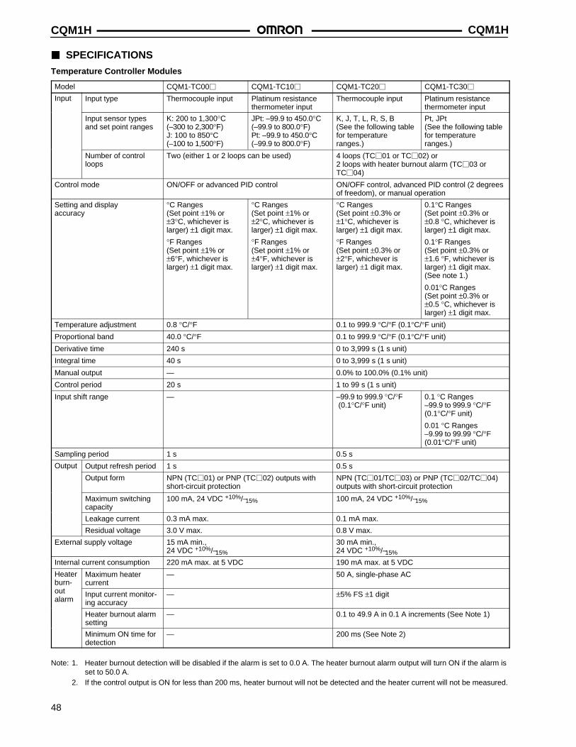
CQM1HCQM1H
48
SPECIFICATIONS
Temperature Controller Modules
Model CQM1-TC00 CQM1-TC10 CQM1-TC20 CQM1-TC30
Input Input type Thermocouple input Platinum resistancethermometer input
Thermocouple input Platinum resistancethermometer input
Input sensor typesand set point ranges
K: 200 to 1,300°C(–300 to 2,300°F)J: 100 to 850°C (–100 to 1,500°F)
JPt: –99.9 to 450.0°C(–99.9 to 800.0°F)Pt: –99.9 to 450.0°C(–99.9 to 800.0°F)
K, J, T, L, R, S, B(See the following tablefor temperatureranges.)
Pt, JPt(See the following tablefor temperatureranges.)
Number of controlloops
Two (either 1 or 2 loops can be used) 4 loops (TC01 or TC02) or 2 loops with heater burnout alarm (TC03 orTC04)
Control mode ON/OFF or advanced PID control ON/OFF control, advanced PID control (2 degreesof freedom), or manual operation
Setting and displayaccuracy
°C Ranges(Set point ±1% or±3°C, whichever islarger) ±1 digit max.
°F Ranges (Set point ±1% or±6°F, whichever islarger) ±1 digit max.
°C Ranges(Set point ±1% or±2°C, whichever islarger) ±1 digit max.
°F Ranges (Set point ±1% or±4°F, whichever islarger) ±1 digit max.
°C Ranges(Set point ±0.3% or±1°C, whichever is larger) ±1 digit max.
°F Ranges (Set point ±0.3% or±2°F, whichever is larger) ±1 digit max.
0.1°C Ranges (Set point ±0.3% or±0.8 °C, whichever islarger) ±1 digit max.
0.1°F Ranges (Set point ±0.3% or±1.6 °F, whichever islarger) ±1 digit max.(See note 1.)
0.01°C Ranges (Set point ±0.3% or±0.5 °C, whichever islarger) ±1 digit max.
Temperature adjustment 0.8 °C/°F 0.1 to 999.9 °C/°F (0.1°C/°F unit)
Proportional band 40.0 °C/°F 0.1 to 999.9 °C/°F (0.1°C/°F unit)
Derivative time 240 s 0 to 3,999 s (1 s unit)
Integral time 40 s 0 to 3,999 s (1 s unit)
Manual output — 0.0% to 100.0% (0.1% unit)
Control period 20 s 1 to 99 s (1 s unit)
Input shift range — –99.9 to 999.9 °C/°F (0.1°C/°F unit)
0.1 °C Ranges–99.9 to 999.9 °C/°F(0.1°C/°F unit)
0.01 °C Ranges–9.99 to 99.99 °C/°F(0.01°C/°F unit)
Sampling period 1 s 0.5 s
Output Output refresh period 1 s 0.5 s
Output form NPN (TC01) or PNP (TC02) outputs withshort-circuit protection
NPN (TC01/TC03) or PNP (TC02/TC04)outputs with short-circuit protection
Maximum switchingcapacity
100 mA, 24 VDC +10%/–15% 100 mA, 24 VDC +10%/–15%
Leakage current 0.3 mA max. 0.1 mA max.
Residual voltage 3.0 V max. 0.8 V max.
External supply voltage 15 mA min., 24 VDC +10%/–15%
30 mA min., 24 VDC +10%/–15%
Internal current consumption 220 mA max. at 5 VDC 190 mA max. at 5 VDC
Heaterburn-
Maximum heater current
— 50 A, single-phase AC
outalarm
Input current monitor-ing accuracy
— ±5% FS ±1 digit
Heater burnout alarmsetting
— 0.1 to 49.9 A in 0.1 A increments (See Note 1)
Minimum ON time fordetection
— 200 ms (See Note 2)
Note: 1. Heater burnout detection will be disabled if the alarm is set to 0.0 A. The heater burnout alarm output will turn ON if the alarm isset to 50.0 A.
2. If the control output is ON for less than 200 ms, heater burnout will not be detected and the heater current will not be measured.
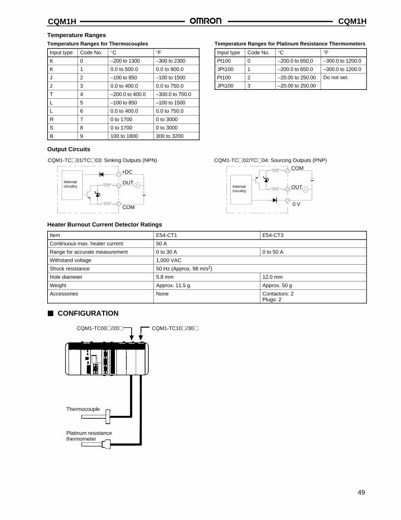
CQM1H CQM1H
49
Temperature RangesTemperature Ranges for Thermocouples
Input type Code No. °C °FK 0 –200 to 1300 –300 to 2300
K 1 0.0 to 500.0 0.0 to 900.0
J 2 –100 to 850 –100 to 1500
J 3 0.0 to 400.0 0.0 to 750.0
T 4 –200.0 to 400.0 –300.0 to 700.0
L 5 –100 to 850 –100 to 1500
L 6 0.0 to 400.0 0.0 to 750.0
R 7 0 to 1700 0 to 3000
S 8 0 to 1700 0 to 3000
B 9 100 to 1800 300 to 3200
Temperature Ranges for Platinum Resistance Thermometers
Input type Code No. °C °FPt100 0 –200.0 to 650.0 –300.0 to 1200.0
JPt100 1 –200.0 to 650.0 –300.0 to 1200.0
Pt100 2 –20.00 to 250.00 Do not set.
JPt100 3 –20.00 to 250.00
Output Circuits
CQM1-TC01/TC03: Sinking Outputs (NPN)
+DC
OUT
COM
CQM1-TC02/TC04: Sourcing Outputs (PNP)
COM
OUT
0 V
Internalcircuitry Internal
circuitry
Heater Burnout Current Detector Ratings
Item E54-CT1 E54-CT3
Continuous max. heater current 50 A
Range for accurate measurement 0 to 30 A 0 to 50 A
Withstand voltage 1,000 VAC
Shock resistance 50 Hz (Approx. 98 m/s2)
Hole diameter 5.8 mm 12.0 mm
Weight Approx. 11.5 g Approx. 50 g
Accessories None Contactors: 2Plugs: 2
CONFIGURATION
Thermocouple
Platinum resistancethermometer
CQM1-TC00/20 CQM1-TC10/30
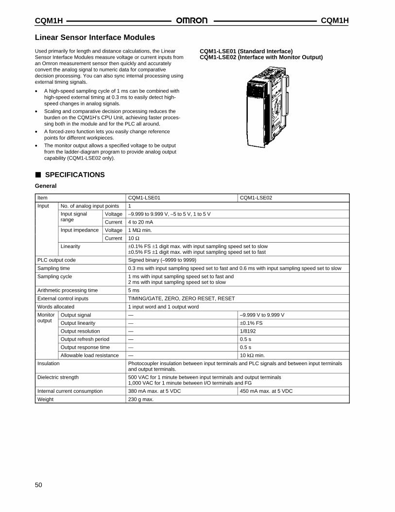
CQM1HCQM1H
50
Linear Sensor Interface Modules
Used primarily for length and distance calculations, the LinearSensor Interface Modules measure voltage or current inputs froman Omron measurement sensor then quickly and accuratelyconvert the analog signal to numeric data for comparativedecision processing. You can also sync internal processing usingexternal timing signals.
• A high-speed sampling cycle of 1 ms can be combined withhigh-speed external timing at 0.3 ms to easily detect high-speed changes in analog signals.
• Scaling and comparative decision processing reduces theburden on the CQM1H’s CPU Unit, achieving faster proces-sing both in the module and for the PLC all around.
• A forced-zero function lets you easily change referencepoints for different workpieces.
• The monitor output allows a specified voltage to be outputfrom the ladder-diagram program to provide analog outputcapability (CQM1-LSE02 only).
CQM1-LSE01 (Standard Interface)CQM1-LSE02 (Interface with Monitor Output)
SPECIFICATIONS
General
Item CQM1-LSE01 CQM1-LSE02
Input No. of analog input points 1
Input signal Voltage –9.999 to 9.999 V, –5 to 5 V, 1 to 5 Vrange Current 4 to 20 mA
Input impedance Voltage 1 MΩ min.
Current 10 ΩLinearity ±0.1% FS ±1 digit max. with input sampling speed set to slow
±0.5% FS ±1 digit max. with input sampling speed set to fast
PLC output code Signed binary (–9999 to 9999)
Sampling time 0.3 ms with input sampling speed set to fast and 0.6 ms with input sampling speed set to slow
Sampling cycle 1 ms with input sampling speed set to fast and 2 ms with input sampling speed set to slow
Arithmetic processing time 5 ms
External control inputs TIMING/GATE, ZERO, ZERO RESET, RESET
Words allocated 1 input word and 1 output word
Monitor Output signal — –9.999 V to 9.999 Voutput Output linearity — ±0.1% FS
Output resolution — 1/8192
Output refresh period — 0.5 s
Output response time — 0.5 s
Allowable load resistance — 10 kΩ min.
Insulation Photocoupler insulation between input terminals and PLC signals and between input terminalsand output terminals.
Dielectric strength 500 VAC for 1 minute between input terminals and output terminals1,000 VAC for 1 minute between I/O terminals and FG
Internal current consumption 380 mA max. at 5 VDC 450 mA max. at 5 VDC
Weight 230 g max.
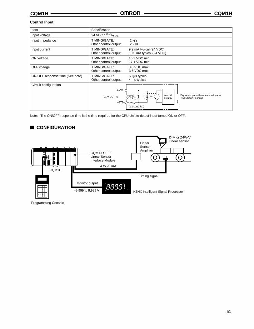
CQM1H CQM1H
51
Control Input
Item Specification
Input voltage 24 VDC +10%/–15%
Input impedance TIMING/GATE: 2 kΩOther control output: 2.2 kΩ
Input current TIMING/GATE: 9.2 mA typical (24 VDC)Other control output: 10.0 mA typical (24 VDC)
ON voltage TIMING/GATE: 16.3 VDC min.Other control output: 17.1 VDC min.
OFF voltage TIMING/GATE: 3.8 VDC max.Other control output: 3.6 VDC max.
ON/OFF response time (See note) TIMING/GATE: 50 µs typicalOther control output: 4 ms typical
Circuit configurationCOM
24 V DC 820 Ω(1.2 kΩ)
2.2 kΩ (2 kΩ)
Internalcircuitry
Figures in parentheses are values forTIMING/GATE input.
Note: The ON/OFF response time is the time required for the CPU Unit to detect input turned ON or OFF.
CONFIGURATION
Programming Console
CQM1H
CQM1-LSE02 Linear Sensor Interface Module
4 to 20 mA
Monitor output
LinearSensorAmplifier
Z4M or Z4W-VLinear sensor
Timing signal
K3NX Intelligent Signal Processor–9,999 to 9,999 V
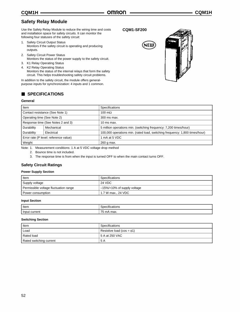
CQM1HCQM1H
52
Safety Relay Module
Use the Safety Relay Module to reduce the wiring time and costsand installation space for safety circuits. It can monitor thefollowing four statuses of the safety circuit:
1. Safety Circuit Output StatusMonitors if the safety circuit is operating and producingoutputs.
2. Safety Circuit Power StatusMonitors the status of the power supply to the safety circuit.
3. K1 Relay Operating Status4. K2 Relay Operating Status
Monitors the status of the internal relays that form the safetycircuit. This helps troubleshooting safety circuit problems.
In addition to the safety circuit, the module offers general-purpose inputs for synchronization: 4 inputs and 1 common.
CQM1-SF200
SPECIFICATIONS
General
Item Specifications
Contact resistance (See Note 1) 100 mΩOperating time (See Note 2) 300 ms max.
Response time (See Notes 2 and 3) 10 ms max.
Durability Mechanical 5 million operations min. (switching frequency: 7,200 times/hour)
Durability Electrical 100,000 operations min. (rated load, switching frequency: 1,800 times/hour)
Error rate (P level: reference value) 1 mA at 5 VDC
Weight 260 g max.
Note: 1. Measurement conditions: 1 A at 5 VDC voltage drop method2. Bounce time is not included.3. The response time is from when the input is turned OFF to when the main contact turns OFF.
Safety Circuit Ratings
Power Supply Section
Item Specifications
Supply voltage 24 VDC
Permissible voltage fluctuation range –15%/+10% of supply voltage
Power consumption 1.7 W max., 24 VDC
Input Section
Item Specifications
Input current 75 mA max.
Switching Section
Item Specifications
Load Resistive load (cos = φ1)
Rated load 5 A at 250 VAC
Rated switching current 5 A
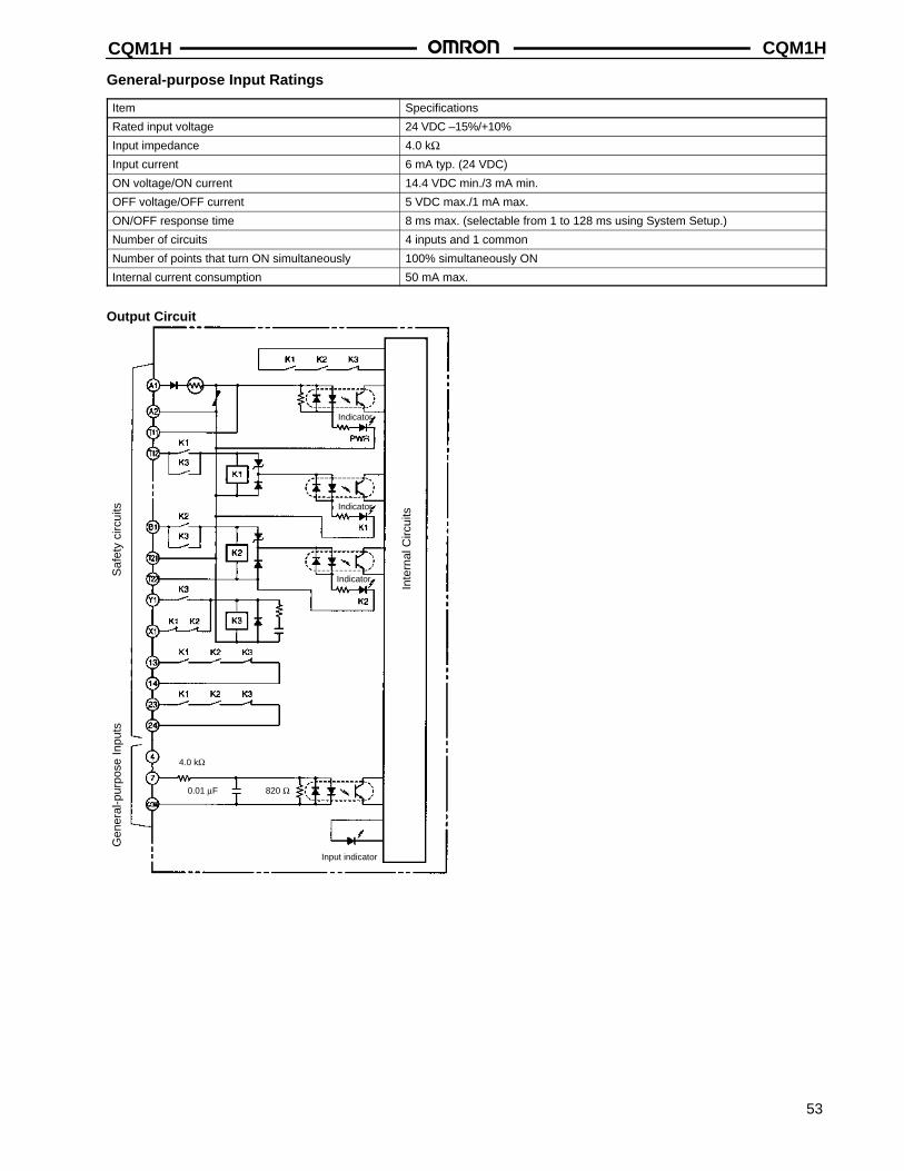
CQM1H CQM1H
53
General-purpose Input Ratings
Item Specifications
Rated input voltage 24 VDC –15%/+10%
Input impedance 4.0 kΩInput current 6 mA typ. (24 VDC)
ON voltage/ON current 14.4 VDC min./3 mA min.
OFF voltage/OFF current 5 VDC max./1 mA max.
ON/OFF response time 8 ms max. (selectable from 1 to 128 ms using System Setup.)
Number of circuits 4 inputs and 1 common
Number of points that turn ON simultaneously 100% simultaneously ON
Internal current consumption 50 mA max.
Output Circuit
Saf
ety
circ
uits
Gen
eral
-pur
pose
Inpu
ts
Inte
rnal
Circ
uits
Indicator
Indicator
Indicator
Input indicator
4.0 kΩ
820 Ω0.01 µF
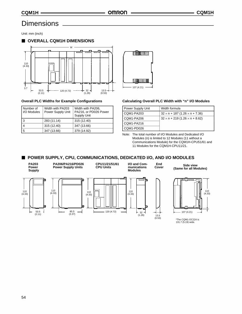
CQM1HCQM1H
54
DimensionsUnit: mm (inch)
OVERALL CQM1H DIMENSIONSW
110(4.33)
53.5(2.11)
3.7120 (4.72) 32
(1.26)13.5
(0.53)
107 (4.21)
Overall PLC Widths for Example Configurations
Number ofI/O Modules
Width with PA203Power Supply Unit
Width with PA206,PA216, or PD026 PowerSupply Unit
3 283 (11.14) 315 (12.40)
4 315 (12.40) 347 (13.66)
5 347 (13.66) 379 (14.92)
Calculating Overall PLC Width with “n” I/O Modules
Power Supply Unit Width formula
CQM1-PA203 32 × n + 187 (1.26 × n + 7.36)
CQM1-PA206 32 × n + 219 (1.26 × n + 8.62)
CQM1-PA216
CQM1-PD026
Note: The total number of I/O Modules and Dedicated I/OModules (n) is limited to 12 Modules (11 without aCommunications Module) for the CQM1H-CPU51/61 and11 Modules for the CQM1H-CPU11/21.
POWER SUPPLY, CPU, COMMUNICATIONS, DEDICATED I/O, AND I/O MODULES
110(4.33)
110(4.33)
32(1.26)
PA203PowerSupply
PA206/PA216/PD026Power Supply Units
CPU11/21/51/61CPU Units
I/O and Com-municationsModules
EndCover Side view
(Same for all Modules)
*The CQM1-OC224 is 131.7 (5.19) wide.
53.5(2.11)
120 (4.72)
13.5(0.53)
107 (4.21)
110(4.33)
85.5(3.37)
110(4.33)
110(4.33)
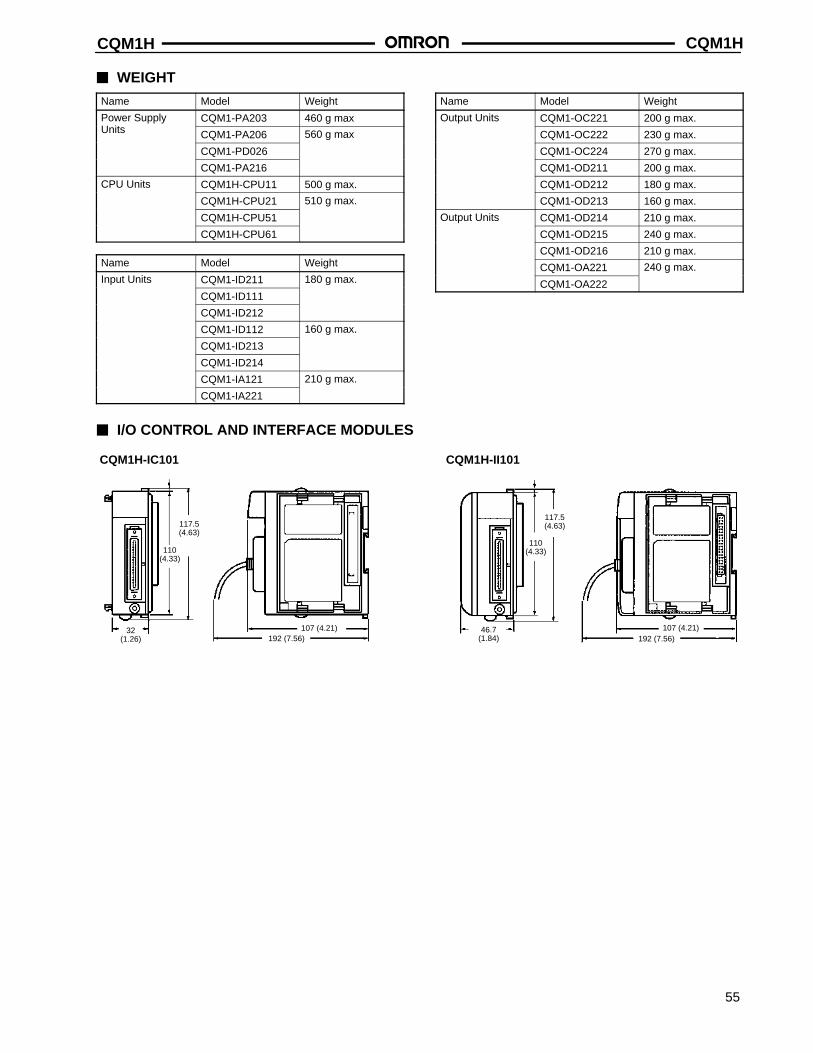
CQM1H CQM1H
55
WEIGHT
Name Model Weight
Power Supply CQM1-PA203 460 g maxUnits CQM1-PA206 560 g max
CQM1-PD026
CQM1-PA216
CPU Units CQM1H-CPU11 500 g max.
CQM1H-CPU21 510 g max.
CQM1H-CPU51
CQM1H-CPU61
Name Model Weight
Input Units CQM1-ID211 180 g max.
CQM1-ID111
CQM1-ID212
CQM1-ID112 160 g max.
CQM1-ID213
CQM1-ID214
CQM1-IA121 210 g max.
CQM1-IA221
Name Model Weight
Output Units CQM1-OC221 200 g max.
CQM1-OC222 230 g max.
CQM1-OC224 270 g max.
CQM1-OD211 200 g max.
CQM1-OD212 180 g max.
CQM1-OD213 160 g max.
Output Units CQM1-OD214 210 g max.
CQM1-OD215 240 g max.
CQM1-OD216 210 g max.
CQM1-OA221 240 g max.
CQM1-OA222
I/O CONTROL AND INTERFACE MODULES
CQM1H-IC101 CQM1H-II101
110(4.33)
110(4.33)
32(1.26) 192 (7.56)
107 (4.21)
117.5(4.63)
107 (4.21)192 (7.56)
46.7(1.84)
117.5(4.63)
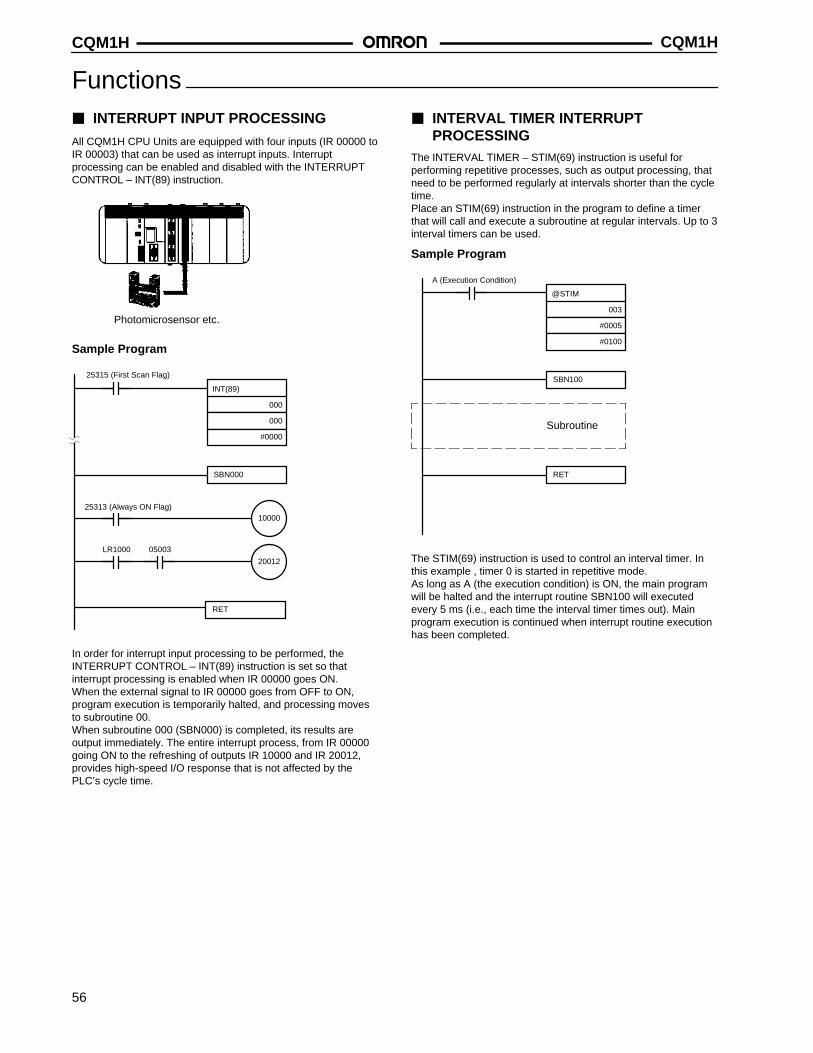
CQM1HCQM1H
56
Functions INTERRUPT INPUT PROCESSING
All CQM1H CPU Units are equipped with four inputs (IR 00000 toIR 00003) that can be used as interrupt inputs. Interruptprocessing can be enabled and disabled with the INTERRUPTCONTROL – INT(89) instruction.
Photomicrosensor etc.
Sample Program
INT(89)
000
000
#0000
SBN000
10000
20012
RET
LR1000 05003
25315 (First Scan Flag)
25313 (Always ON Flag)
In order for interrupt input processing to be performed, theINTERRUPT CONTROL – INT(89) instruction is set so thatinterrupt processing is enabled when IR 00000 goes ON.When the external signal to IR 00000 goes from OFF to ON,program execution is temporarily halted, and processing movesto subroutine 00.When subroutine 000 (SBN000) is completed, its results areoutput immediately. The entire interrupt process, from IR 00000going ON to the refreshing of outputs IR 10000 and IR 20012,provides high-speed I/O response that is not affected by thePLC’s cycle time.
INTERVAL TIMER INTERRUPT PROCESSING
The INTERVAL TIMER – STIM(69) instruction is useful forperforming repetitive processes, such as output processing, thatneed to be performed regularly at intervals shorter than the cycletime.Place an STIM(69) instruction in the program to define a timerthat will call and execute a subroutine at regular intervals. Up to 3interval timers can be used.
Sample Program
@STIM
003
#0005
#0100
SBN100
RET
Subroutine
A (Execution Condition)
The STIM(69) instruction is used to control an interval timer. Inthis example , timer 0 is started in repetitive mode.As long as A (the execution condition) is ON, the main programwill be halted and the interrupt routine SBN100 will executedevery 5 ms (i.e., each time the interval timer times out). Mainprogram execution is continued when interrupt routine executionhas been completed.
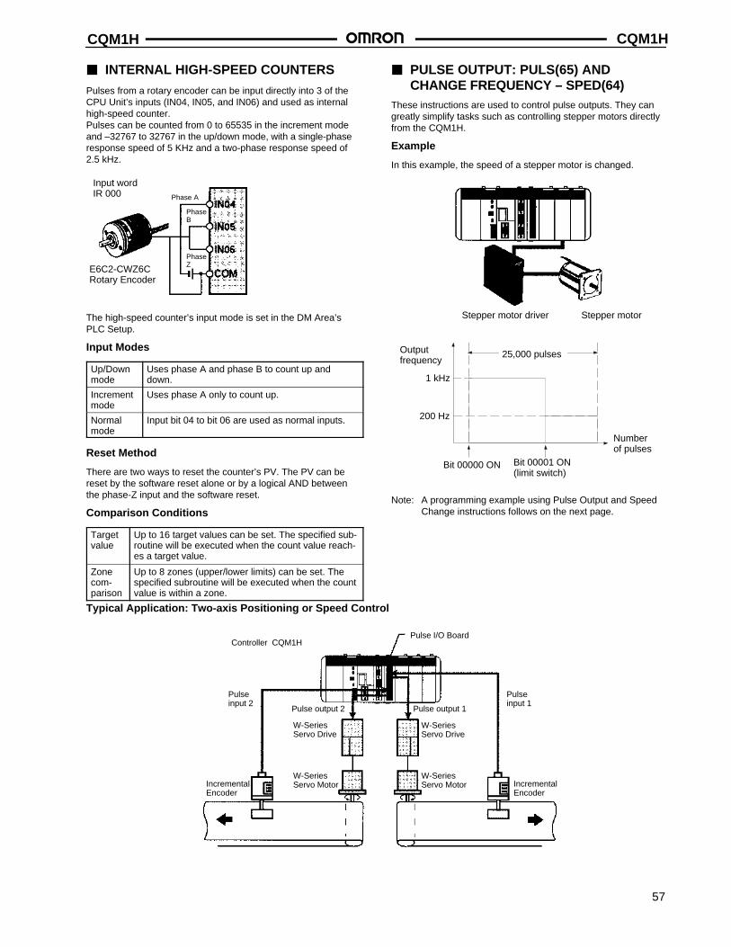
CQM1H CQM1H
57
INTERNAL HIGH-SPEED COUNTERS
Pulses from a rotary encoder can be input directly into 3 of theCPU Unit’s inputs (IN04, IN05, and IN06) and used as internalhigh-speed counter.Pulses can be counted from 0 to 65535 in the increment modeand –32767 to 32767 in the up/down mode, with a single-phaseresponse speed of 5 KHz and a two-phase response speed of2.5 kHz.
E6C2-CWZ6CRotary Encoder
Phase A
PhaseZ
PhaseB
Input word IR 000
The high-speed counter’s input mode is set in the DM Area’sPLC Setup.
Input Modes
Up/Downmode
Uses phase A and phase B to count up anddown.
Incrementmode
Uses phase A only to count up.
Normalmode
Input bit 04 to bit 06 are used as normal inputs.
Reset Method
There are two ways to reset the counter’s PV. The PV can bereset by the software reset alone or by a logical AND betweenthe phase-Z input and the software reset.
Comparison Conditions
Targetvalue
Up to 16 target values can be set. The specified sub-routine will be executed when the count value reach-es a target value.
Zonecom-parison
Up to 8 zones (upper/lower limits) can be set. Thespecified subroutine will be executed when the countvalue is within a zone.
PULSE OUTPUT: PULS(65) ANDCHANGE FREQUENCY – SPED(64)
These instructions are used to control pulse outputs. They cangreatly simplify tasks such as controlling stepper motors directlyfrom the CQM1H.
Example
In this example, the speed of a stepper motor is changed.
Stepper motor driver Stepper motor
Outputfrequency
1 kHz
200 Hz
25,000 pulses
Bit 00000 ON Bit 00001 ON(limit switch)
Numberof pulses
Note: A programming example using Pulse Output and SpeedChange instructions follows on the next page.
Typical Application: Two-axis Positioning or Speed Control
Pulse I/O BoardController CQM1H
Pulseinput 2
Pulse output 2
IncrementalEncoder
Pulse output 1
Pulseinput 1
IncrementalEncoder
W-SeriesServo Motor
W-SeriesServo Drive
W-SeriesServo Motor
W-SeriesServo Drive
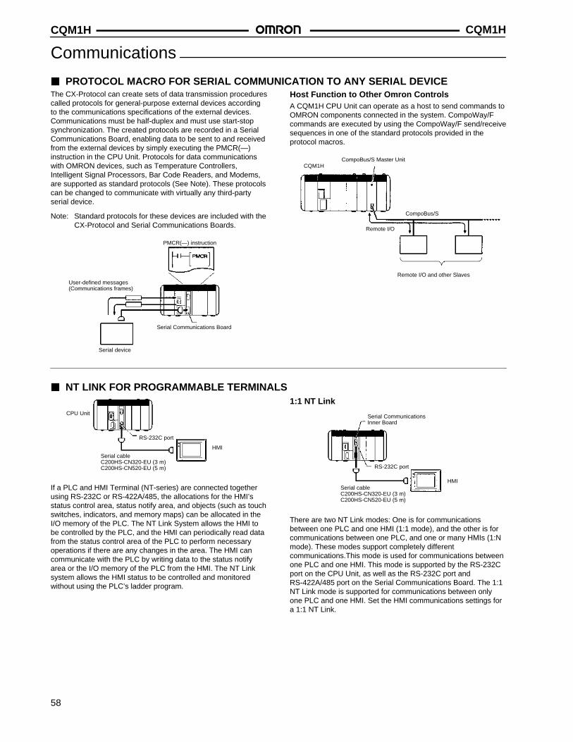
CQM1HCQM1H
58
Communications
PROTOCOL MACRO FOR SERIAL COMMUNICATION TO ANY SERIAL DEVICEThe CX-Protocol can create sets of data transmission procedurescalled protocols for general-purpose external devices accordingto the communications specifications of the external devices.Communications must be half-duplex and must use start-stopsynchronization. The created protocols are recorded in a SerialCommunications Board, enabling data to be sent to and receivedfrom the external devices by simply executing the PMCR(—)instruction in the CPU Unit. Protocols for data communicationswith OMRON devices, such as Temperature Controllers,Intelligent Signal Processors, Bar Code Readers, and Modems,are supported as standard protocols (See Note). These protocolscan be changed to communicate with virtually any third-partyserial device.
Note: Standard protocols for these devices are included with theCX-Protocol and Serial Communications Boards.
Serial Communications Board
PMCR(—) instruction
User-defined messages(Communications frames)
Serial device
Host Function to Other Omron ControlsA CQM1H CPU Unit can operate as a host to send commands toOMRON components connected in the system. CompoWay/Fcommands are executed by using the CompoWay/F send/receivesequences in one of the standard protocols provided in theprotocol macros.
CompoBus/S Master Unit
CompoBus/S
Remote I/O
CQM1H
Remote I/O and other Slaves
NT LINK FOR PROGRAMMABLE TERMINALS
CPU Unit
RS-232C port
HMI
Serial cableC200HS-CN320-EU (3 m)C200HS-CN520-EU (5 m)
If a PLC and HMI Terminal (NT-series) are connected togetherusing RS-232C or RS-422A/485, the allocations for the HMI’sstatus control area, status notify area, and objects (such as touchswitches, indicators, and memory maps) can be allocated in theI/O memory of the PLC. The NT Link System allows the HMI tobe controlled by the PLC, and the HMI can periodically read datafrom the status control area of the PLC to perform necessaryoperations if there are any changes in the area. The HMI cancommunicate with the PLC by writing data to the status notifyarea or the I/O memory of the PLC from the HMI. The NT Linksystem allows the HMI status to be controlled and monitoredwithout using the PLC’s ladder program.
1:1 NT Link
Serial CommunicationsInner Board
RS-232C port
HMISerial cableC200HS-CN320-EU (3 m)C200HS-CN520-EU (5 m)
There are two NT Link modes: One is for communicationsbetween one PLC and one HMI (1:1 mode), and the other is forcommunications between one PLC, and one or many HMIs (1:Nmode). These modes support completely differentcommunications.This mode is used for communications betweenone PLC and one HMI. This mode is supported by the RS-232Cport on the CPU Unit, as well as the RS-232C port andRS-422A/485 port on the Serial Communications Board. The 1:1NT Link mode is supported for communications between onlyone PLC and one HMI. Set the HMI communications settings fora 1:1 NT Link.
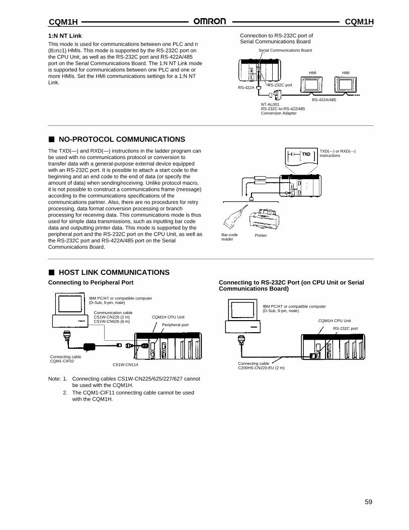
CQM1H CQM1H
59
1:N NT LinkThis mode is used for communications between one PLC and n(8≥n≥1) HMIs. This mode is supported by the RS-232C port onthe CPU Unit, as well as the RS-232C port and RS-422A/485port on the Serial Communications Board. The 1:N NT Link modeis supported for communications between one PLC and one ormore HMIs. Set the HMI communications settings for a 1:N NTLink.
NT-AL001RS-232C-to-RS-422/485Conversion Adapter
RS-232C port
RS-422A/485
RS-422A
HMI HMI
Serial Communications Board
Connection to RS-232C port ofSerial Communications Board
NO-PROTOCOL COMMUNICATIONSThe TXD(—) and RXD(—) instructions in the ladder program canbe used with no communications protocol or conversion totransfer data with a general-purpose external device equippedwith an RS-232C port. It is possible to attach a start code to thebeginning and an end code to the end of data (or specify theamount of data) when sending/receiving. Unlike protocol macro,it is not possible to construct a communications frame (message)according to the communications specifications of thecommunications partner. Also, there are no procedures for retryprocessing, data format conversion processing or branchprocessing for receiving data. This communications mode is thusused for simple data transmissions, such as inputting bar codedata and outputting printer data. This mode is supported by theperipheral port and the RS-232C port on the CPU Unit, as well asthe RS-232C port and RS-422A/485 port on the SerialCommunications Board.
Bar-code reader
Printer
TXD(—) or RXD(—)instructions
HOST LINK COMMUNICATIONSConnecting to Peripheral Port
IBM PC/AT or compatible computer(D-Sub, 9-pin, male)
Connecting cableCQM1-CIF02
CQM1H CPU Unit
Peripheral port
CS1W-CN114
Communication cableCS1W-CN226 (2 m)CS1W-CN626 (6 m)
Note: 1. Connecting cables CS1W-CN225/625/227/627 cannotbe used with the CQM1H.
2. The CQM1-CIF11 connecting cable cannot be usedwith the CQM1H.
Connecting to RS-232C Port (on CPU Unit or SerialCommunications Board)
CQM1H CPU Unit
RS-232C port
Connecting cableC200HS-CN220-EU (2 m)
IBM PC/AT or compatible computer(D-Sub, 9-pin, male)
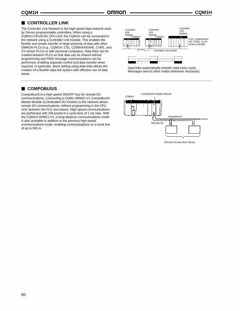
CQM1HCQM1H
60
CONTROLLER LINKThe Controller Link Network is the high-speed data network usedby Omron programmable controllers. When using aCQM1H-CPU51/61 CPU Unit, the CQM1H can be connected tothe network using a Controller Link module. This enables theflexible and simple transfer of large amounts of data with otherOMRON PLCs (e.g., CQM1H, CS1, C200HX/HG/HE, CVM1, andCV-series PLCs) or with personal computers. Data links can becreated between PLCs so that data can be shared withoutprogramming and FINS message communications can beperformed, enabling separate control and data transfer whenrequired. In particular, direct setting using data links allows thecreation of a flexible data link system with effective use of dataareas.
Controller Link Module
Messages sent to other nodes whenever necessary.
Controller Link (wired)
Data links automatically transfer data every cycle.
CQM1HCS1, C200HX/HG/HE, CVM1, or CV-series controller
Controller Link Module
CQM1H
Controller Link Module
COMPOBUS/SCompoBus/S is a high-speed ON/OFF bus for remote I/Ocommunications. Connecting a CQM1-SRM21-V1 CompoBus/SMaster Module (a Dedicated I/O module) to the network allowsremote I/O communications, without programming in the CPUUnit, between the PLC and slaves. High-speed communicationsare performed with 256 points in a cycle time of 1 ms max. Withthe CQM1H-SRM21-V1, a long-distance communications modeis also available in addition to the previous high-speedcommunications mode, enabling communications on a trunk lineof up to 500 m.
CompoBus/S Master Module
CompoBus/S
Remote I/O
CQM1H
Remote I/O and other Slaves
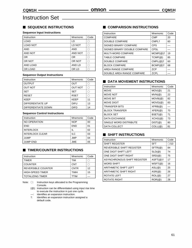
CQM1H CQM1H
61
Instruction Set
SEQUENCE INSTRUCTIONS
Sequence Input Instructions
Instruction Mnemonic Code
LOAD LD
LOAD NOT LD NOT
AND AND
AND NOT AND NOT
OR OR
OR NOT OR NOT
AND LOAD AND LD
OR LOAD OR LD
Sequence Output Instructions
Instruction Mnemonic Code
OUTPUT OUT
OUT NOT OUT NOT
SET SET
RESET RSET
KEEP KEEP 11
DIFFERENTIATE UP DIFU 13
DIFFERENTIATE DOWN DIFD 14
Sequence Control Instructions
Instruction Mnemonic Code
NO OPERATION NOP 00
END END 01
INTERLOCK IL 02
INTERLOCK CLEAR ILC 03
JUMP JMP 04
JUMP END JME 05
TIMER/COUNTER INSTRUCTIONS
Instruction Mnemonic Code
TIMER TIM
COUNTER CNT
REVERSIBLE COUNTER CNTR 12
HIGH-SPEED TIMER TIMH 15
TOTALIZING TIMER TTIM ––
Note: : Instruction keys allocated to the Programming Console.
(@): Instruction can be differentiated using input rise timeto execute the instruction in just one cycle.
––: Identifies an expansion instruction.†: Identifies an expansion instruction assigned a
default code.
COMPARISON INSTRUCTIONS
Instruction Mnemonic Code
COMPARE CMP 20
DOUBLE COMPARE CMPL† 60
SIGNED BINARY COMPARE CPS ––
SIGNED BINARY DOUBLE COMPARE CPSL ––
MULTI-WORD COMPARE MCMP(@)† 19
TABLE COMPARE TCMP(@) 85
DOUBLE COMPARE CMPL(@)† 60
BLOCK COMPARE BCMP(@)† 68
AREA RANGE COMPARE ZCP ––
DOUBLE AREA RANGE COMPARE ZCPL ––
DATA MOVEMENT INSTRUCTIONSInstruction Mnemonic Code
MOVE MOV(@) 21
MOVE NOT MVN(@) 22
MOVE BIT MOVB(@) 82
MOVE DIGIT MOVD(@) 83
TRANSFER BITS XFRB(@) ––
BLOCK TRANSFER XFER(@) 70
BLOCK SET BSET(@) 71
DATA EXCHANGE XCHG(@) 73
SINGLE WORD DISTRIBUTE DIST(@) 80
DATA COLLECT COLL(@) 81
SHIFT INSTRUCTIONSInstruction Mnemonic Code
SHIFT REGISTER SFT /10
REVERSIBLE SHIFT REGISTER SFTR(@) 84
ONE DIGIT SHIFT LEFT SLD(@) 74
ONE DIGIT SHIFT RIGHT SRD(@) 75
ASYNCHRONOUS SHIFT REGISTER ASFT(@)† 17
WORD SHIFT WSFT(@) 16
ARITHMETIC SHIFT LEFT ASL(@) 25
ARITHMETIC SHIFT RIGHT ASR(@) 26
ROTATE LEFT ROL(@) 27
ROTATE RIGHT ROR(@) 28
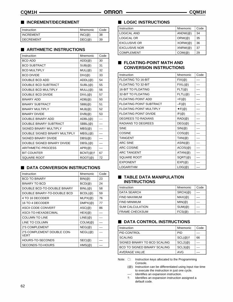
CQM1HCQM1H
62
INCREMENT/DECREMENT
Instruction Mnemonic Code
INCREMENT INC(@) 38
DECREMENT DEC(@) 39
ARITHMETIC INSTRUCTIONSInstruction Mnemonic Code
BCD ADD ADD(@) 30
BCD SUBTRACT SUB(@) 31
BCD MULTIPLY MUL(@) 32
BCD DIVIDE DIV(@) 33
DOUBLE BCD ADD ADDL(@) 54
DOUBLE BCD SUBTRACT SUBL(@) 55
DOUBLE BCD MULTIPLY MULL(@) 56
DOUBLE BCD DIVIDE DIVL(@) 57
BINARY ADD ADB(@) 50
BINARY SUBTRACT SBB(@) 51
BINARY MULTIPLY MLB(@) 52
BINARY DIVIDE DVB(@) 53
DOUBLE BINARY ADD ADBL(@) ––
DOUBLE BINARY SUBTRACT SBBL(@) ––
SIGNED BINARY MULTIPLY MBS(@) ––
DOUBLE SIGNED BINARY MULTIPLY MBSL(@) ––
SIGNED BINARY DIVIDE DBS(@) ––
DOUBLE SIGNED BINARY DIVIDE DBSL(@) ––
ARITHMETIC PROCESS APR(@) ––
BIT COUNTER BCNT(@)† 67
SQUARE ROOT ROOT(@) 72
DATA CONVERSION INSTRUCTIONSInstruction Mnemonic Code
BCD TO BINARY BIN(@) 23
BINARY TO BCD BCD(@) 24
DOUBLE BCD-TO-DOUBLE BINARY BINL(@) 58
DOUBLE BINARY-TO-DOUBLE BCD BCDL(@) 59
4 TO 16 DECODER MLPX(@) 76
16 TO 4 DECODER DMPX(@) 77
ASCII CODE CONVERT ASC(@) 86
ASCII-TO-HEXADECIMAL HEX(@) ––
COLUMN TO LINE LINE(@) ––
LINE TO COLUMN COLM(@) ––
2’S COMPLEMENT NEG(@) ––
2’S COMPLEMENT DOUBLE CON-VERT
NEGL(@) ––
HOURS-TO-SECONDS SEC(@) ––
SECONDS-TO-HOURS HMS(@) ––
LOGIC INSTRUCTIONSInstruction Mnemonic Code
LOGICAL AND ANDW(@) 34
LOGICAL OR ORW(@) 35
EXCLUSIVE OR XORW(@) 36
EXCLUSIVE NOR XNRW(@) 37
COMPLEMENT COM(@) 29
FLOATING-POINT MATH AND CONVERSION INSTRUCTIONS
Instruction Mnemonic Code
FLOATING TO 16-BIT FIX(@) ––
FLOATING TO 32-BIT FIXL(@) ––
16-BIT TO FLOATING FLT(@) ––
32-BIT TO FLOATING FLTL(@) ––
FLOATING POINT ADD +F(@) ––
FLOATING POINT SUBTRACT –F(@) ––
FLOATING POINT MULTIPLY F(@) ––
FLOATING POINT DIVIDE /F(@) ––
DEGREES TO RADIANS RAD(@) ––
RADIANS TO DEGREES DEG(@) ––
SINE SIN(@) ––
COSINE COS(@) ––
TANGENT TAN(@) ––
ARC SINE ASIN(@) ––
ARC COSINE ACOS(@) ––
ARC TANGENT ATAN(@) ––
SQUARE ROOT SQRT(@) ––
EXPONENT EXP(@) ––
LOGARITHM LOG(@) ––
TABLE DATA MANIPULATION INSTRUCTIONS
Instruction Mnemonic Code
DATA SEARCH SRCH(@) ––
FIND MAXIMUM MAX(@) ––
FIND MINIMUM MIN(@) ––
SUM CALCULATION SUM(@) ––
FRAME CHECKSUM FCS(@) ––
DATA CONTROL INSTRUCTIONSInstruction Mnemonic Code
PID CONTROL PID ––
SCALING SCL(@)† 66
SIGNED BINARY TO BCD SCALING SCL2(@) ––
BCD TO SIGNED BINARY SCALING SCL3(@) ––
AVERAGE VALUE AVG ––
Note: : Instruction keys allocated to the Programming Console.
(@): Instruction can be differentiated using input rise timeto execute the instruction in just one cycle.
––: Identifies an expansion instruction.†: Identifies an expansion instruction assigned a
default code.
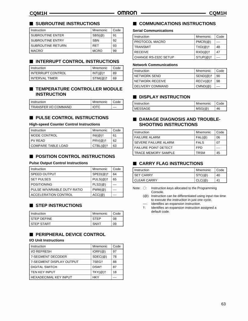
CQM1H CQM1H
63
SUBROUTINE INSTRUCTIONSInstruction Mnemonic Code
SUBROUTINE ENTER SBS(@) 91
SUBROUTINE ENTRY SBN 92
SUBROUTINE RETURN RET 93
MACRO MCRO 99
INTERRUPT CONTROL INSTRUCTIONSInstruction Mnemonic Code
INTERRUPT CONTROL INT(@)† 89
INTERVAL TIMER STIM(@)† 69
TEMPERATURE CONTROLLER MODULEINSTRUCTION
Instruction Mnemonic Code
TRANSFER I/O COMMAND IOTC ––
PULSE CONTROL INSTRUCTIONSHigh-speed Counter Control Instructions
Instruction Mnemonic Code
MODE CONTROL INI(@)† 61
PV READ PRV(@)† 62
COMPARE TABLE LOAD CTBL(@)† 63
POSITION CONTROL INSTRUCTIONSPulse Output Control Instructions
Instruction Mnemonic Code
SPEED OUTPUT SPED(@)† 64
SET PULSES PULS(@)† 65
POSITIONING PLS2(@) ––
PULSE W/VARIABLE DUTY RATIO PWM(@) ––
ACCELERATION CONTROL ACC(@) ––
STEP INSTRUCTIONS
Instruction Mnemonic Code
STEP DEFINE STEP 08
STEP START SNXT 09
PERIPHERAL DEVICE CONTROLI/O Unit Instructions
Instruction Mnemonic Code
I/O REFRESH IORF(@) 97
7-SEGMENT DECODER SDEC(@) 78
7-SEGMENT DISPLAY OUTPUT 7SEG† 88
DIGITAL SWITCH DSW† 87
TEN KEY INPUT TKY(@)† 18
HEXADECIMAL KEY INPUT HKY ––
COMMUNICATIONS INSTRUCTIONS
Serial Communications
Instruction Mnemonic Code
PROTOCOL MACRO PMCR(@) ––
TRANSMIT TXD(@)† 48
RECEIVE RXD(@)† 47
CHANGE RS-232C SETUP STUP(@)† ––
Network Communications
Instruction Mnemonic Code
NETWORK SEND SEND(@)† 90
NETWORK RECEIVE RECV(@)† 98
DELIVERY COMMAND CMND(@) ––
DISPLAY INSTRUCTIONInstruction Mnemonic Code
MESSAGE MSG(@) 46
DAMAGE DIAGNOSIS AND TROUBLE-SHOOTING INSTRUCTIONS
Instruction Mnemonic Code
FAILURE ALARM FAL(@) 06
SEVERE FAILURE ALARM FALS 07
FAILURE POINT DETECT FPD ––
TRACE MEMORY SAMPLE TRSM 45
CARRY FLAG INSTRUCTIONSInstruction Mnemonic Code
SET CARRY STC(@) 40
CLEAR CARRY CLC(@) 41
Note: : Instruction keys allocated to the Programming Console.
(@): Instruction can be differentiated using input rise timeto execute the instruction in just one cycle.
––: Identifies an expansion instruction.†: Identifies an expansion instruction assigned a
default code.
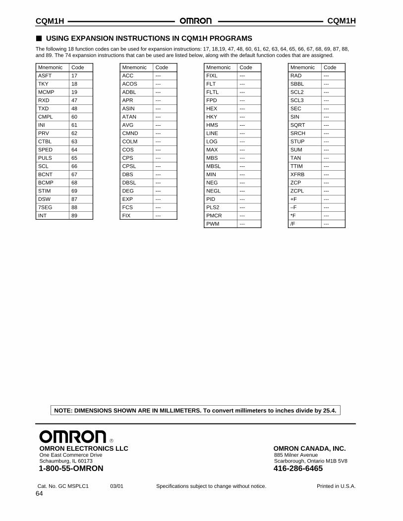
CQM1HCQM1H
64
USING EXPANSION INSTRUCTIONS IN CQM1H PROGRAMSThe following 18 function codes can be used for expansion instructions: 17, 18,19, 47, 48, 60, 61, 62, 63, 64, 65, 66, 67, 68, 69, 87, 88,and 89. The 74 expansion instructions that can be used are listed below, along with the default function codes that are assigned.
Mnemonic Code
ASFT 17
TKY 18
MCMP 19
RXD 47
TXD 48
CMPL 60
INI 61
PRV 62
CTBL 63
SPED 64
PULS 65
SCL 66
BCNT 67
BCMP 68
STIM 69
DSW 87
7SEG 88
INT 89
Mnemonic Code
ACC ---
ACOS ---
ADBL ---
APR ---
ASIN ---
ATAN ---
AVG ---
CMND ---
COLM ---
COS ---
CPS ---
CPSL ---
DBS ---
DBSL ---
DEG ---
EXP ---
FCS ---
FIX ---
Mnemonic Code
FIXL ---
FLT ---
FLTL ---
FPD ---
HEX ---
HKY ---
HMS ---
LINE ---
LOG ---
MAX ---
MBS ---
MBSL ---
MIN ---
NEG ---
NEGL ---
PID ---
PLS2 ---
PMCR ---
PWM ---
Mnemonic Code
RAD ---
SBBL ---
SCL2 ---
SCL3 ---
SEC ---
SIN ---
SQRT ---
SRCH ---
STUP ---
SUM ---
TAN ---
TTIM ---
XFRB ---
ZCP ---
ZCPL ---
+F ---
–F ---
*F ---
/F ---
Cat. No. GC MSPLC1 03/01 Specifications subject to change without notice. Printed in U.S.A.
OMRON ELECTRONICS LLCOne East Commerce DriveSchaumburg, IL 60173
NOTE: DIMENSIONS SHOWN ARE IN MILLIMETERS. To convert millimeters to inches divide by 25.4.
1-800-55-OMRON
OMRON CANADA, INC.885 Milner AvenueScarborough, Ontario M1B 5V8
416-286-6465