Embed Size (px)
Citation preview
Catalogue October
03
Programmable controllersTWIDOMore flexibility tosimplify machine control


1
Contents Twido programmable controller
Extended functions with version 2.0 of TwidoSoft software and controller versions u 2.0 (1):
n Integration of the new AS-interface Master module (M3 profile) in the Twido programmable controller range, allowing management of 62 slaves and 7 analogue modules with profile S7-3.
n Updating of TwidoSoft software on a PC (required configuration: Windows 98, 2000 or XP) for connection to the Twido controller using a serial port, a modem or a USB port (Windows 2000 or XP).
n PID (14 PID loops) and Event Processing functions available.
n Programming: Double words, Arithmetic, Variables, Trigonometrical
(1) Twido programmable controllers in versions lower than 2.0 can be updated to take advantage of these new functions. Updating of Twido controller "firmware" using TwidoSoft software is carried out via the "Tools menu: update PLC microprogram"
Twido programmable base controllersSelection guide . . . . . . . . . . . . . . . . . . . . . . . . . . . . . . . . . . . . . . . . pages 2 and 3
b Compact base controllers . . . . . . . . . . . . . . . . . . . . . . . . . . . . . . . . . pages 4 to 9
b Modular base controllers . . . . . . . . . . . . . . . . . . . . . . . . . . . . . . . . pages 10 to 15
Discrete I/O modulesSelection guide . . . . . . . . . . . . . . . . . . . . . . . . . . . . . . . . . . . . . . . . pages 16 to 19
b Discrete I/O modules . . . . . . . . . . . . . . . . . . . . . . . . . . . . . . . . . . . pages 20 to 25
b Master module for AS-Interface bus . . . . . . . . . . . . . . . . . . . . . . pages 32 and 33
Analogue I/O modulesSelection guide . . . . . . . . . . . . . . . . . . . . . . . . . . . . . . . . . . . . . . pages 26 and 27
b Analogue I/O modules . . . . . . . . . . . . . . . . . . . . . . . . . . . . . . . . . . pages 28 to 31
b Master module for AS-Interface bus . . . . . . . . . . . . . . . . . . . . . . pages 32 and 33
Extension modules for communicationb Communication, communication protocols . . . . . . . . . . . . . . . . . . pages 34 to 37
b Pre-wired solutions . . . . . . . . . . . . . . . . . . . . . . . . . . . . . . . . . . . pages 38 and 39
TwidoSoft programming softwareb TwidoSoft programming software . . . . . . . . . . . . . . . . . . . . . . . . . pages 40 to 47
Servicesb Schneider Electric worldwide. . . . . . . . . . . . . . . . . . . . . . . . . . . . . pages 48 to 53
b Community regulations and Protective treatment . . . . . . . . . . . . . . . . . . . page 54
2
Selection guide 0 Twido programmable controller 0
Compact and modular base controllers
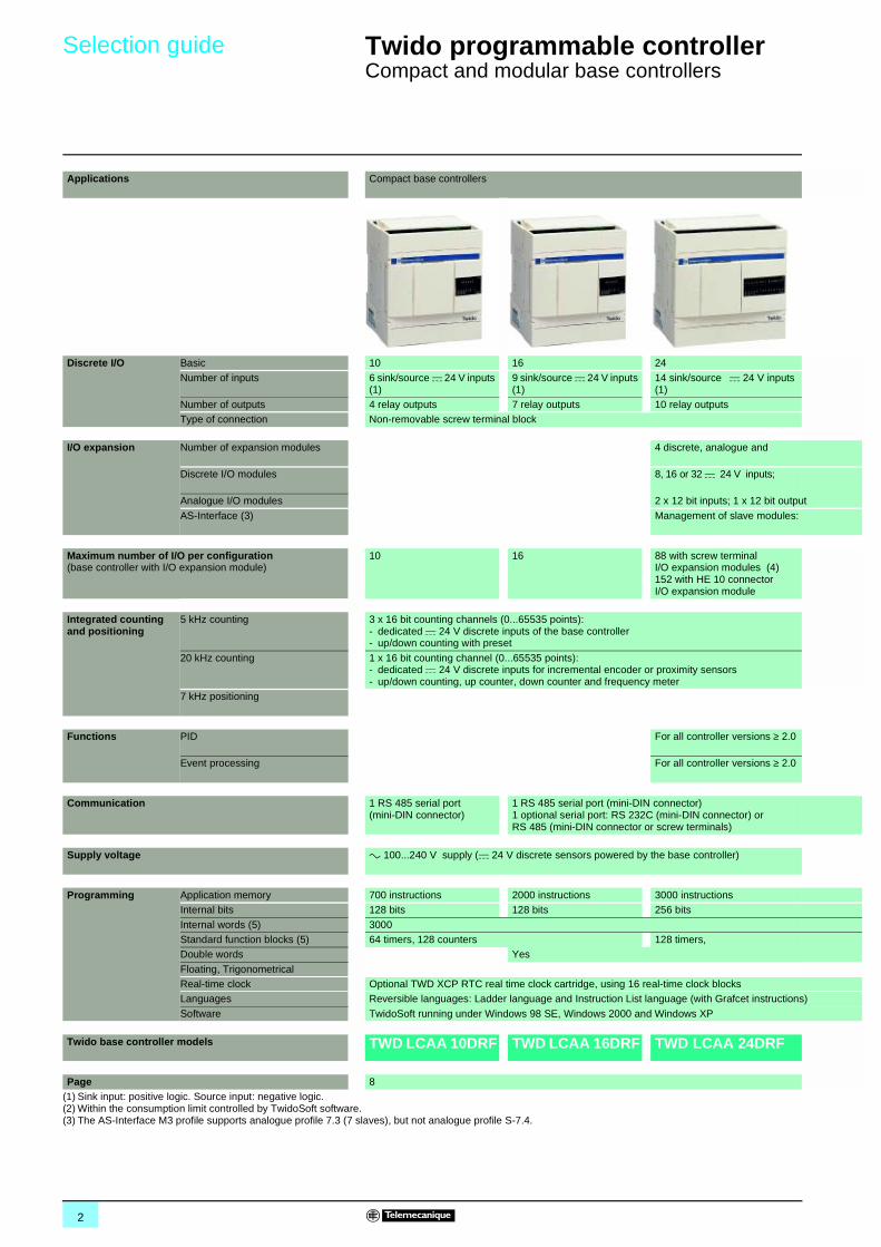
Applications Compact base controllers
Discrete I/O Basic 10 16 24
Number of inputs 6 sink/source c 24 V inputs (1)
9 sink/source c 24 V inputs (1)
14 sink/source c 24 V inputs (1)
Number of outputs 4 relay outputs 7 relay outputs 10 relay outputsType of connection Non-removable screw terminal block
I/O expansion Number of expansion modules 4 discrete, analogue and
Discrete I/O modules 8, 16 or 32 c 24 V inputs;
Analogue I/O modules 2 x 12 bit inputs; 1 x 12 bit output
AS-Interface (3) Management of slave modules:
Maximum number of I/O per configuration(base controller with I/O expansion module)
10 16 88 with screw terminal I/O expansion modules (4)152 with HE 10 connector I/O expansion module
Integrated counting and positioning
5 kHz counting 3 x 16 bit counting channels (0...65535 points):- dedicated c 24 V discrete inputs of the base controller - up/down counting with preset
20 kHz counting 1 x 16 bit counting channel (0...65535 points): - dedicated c 24 V discrete inputs for incremental encoder or proximity sensors- up/down counting, up counter, down counter and frequency meter
7 kHz positioning
Functions PID For all controller versions ≥ 2.0
Event processing For all controller versions ≥ 2.0
Communication 1 RS 485 serial port (mini-DIN connector)
1 RS 485 serial port (mini-DIN connector)1 optional serial port: RS 232C (mini-DIN connector) or RS 485 (mini-DIN connector or screw terminals)
Supply voltage a 100...240 V supply (c 24 V discrete sensors powered by the base controller)
Programming Application memory 700 instructions 2000 instructions 3000 instructionsInternal bits 128 bits 128 bits 256 bits
Internal words (5) 3000Standard function blocks (5) 64 timers, 128 counters 128 timers,Double words Yes
Floating, TrigonometricalReal-time clock Optional TWD XCP RTC real time clock cartridge, using 16 real-time clock blocksLanguages Reversible languages: Ladder language and Instruction List language (with Grafcet instructions)
Software TwidoSoft running under Windows 98 SE, Windows 2000 and Windows XP
Twido base controller models TWD LCAA 10DRF TWD LCAA 16DRF TWD LCAA 24DRF
Page 8(1) Sink input: positive logic. Source input: negative logic.(2) Within the consumption limit controlled by TwidoSoft software.(3) The AS-Interface M3 profile supports analogue profile 7.3 (7 slaves), but not analogue profile S-7.4.
3
00
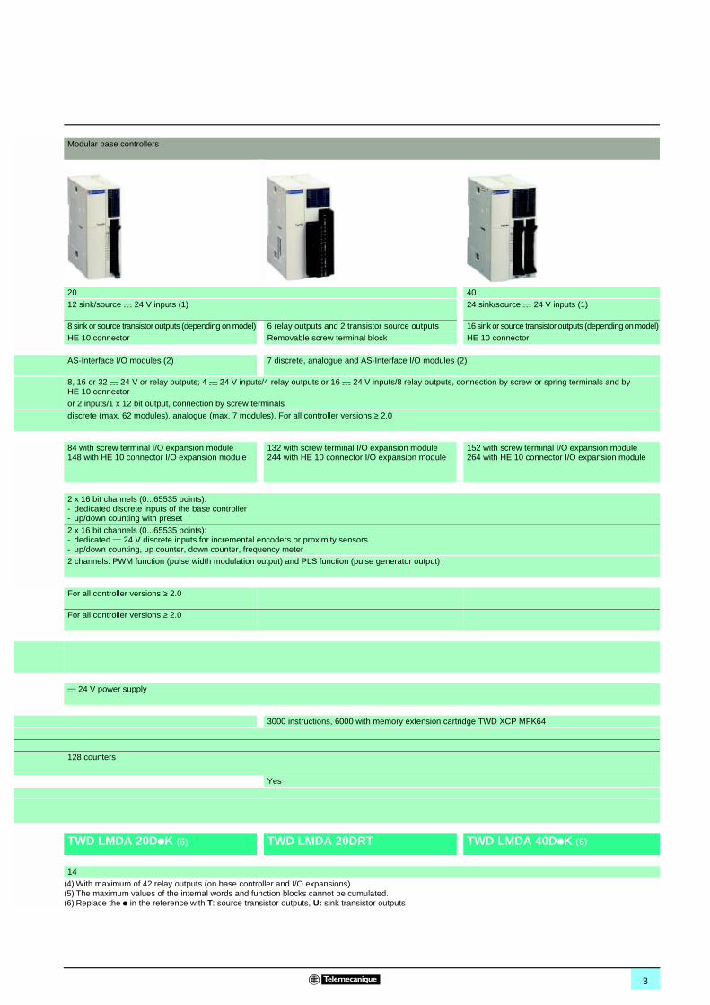
Modular base controllers
20 40
12 sink/source c 24 V inputs (1) 24 sink/source c 24 V inputs (1)
8 sink or source transistor outputs (depending on model) 6 relay outputs and 2 transistor source outputs 16 sink or source transistor outputs (depending on model)HE 10 connector Removable screw terminal block HE 10 connector
AS-Interface I/O modules (2) 7 discrete, analogue and AS-Interface I/O modules (2)
8, 16 or 32 c 24 V or relay outputs; 4 c 24 V inputs/4 relay outputs or 16 c 24 V inputs/8 relay outputs, connection by screw or spring terminals and by HE 10 connector
or 2 inputs/1 x 12 bit output, connection by screw terminals
discrete (max. 62 modules), analogue (max. 7 modules). For all controller versions ≥ 2.0
84 with screw terminal I/O expansion module148 with HE 10 connector I/O expansion module
132 with screw terminal I/O expansion module244 with HE 10 connector I/O expansion module
152 with screw terminal I/O expansion module264 with HE 10 connector I/O expansion module
2 x 16 bit channels (0...65535 points):- dedicated discrete inputs of the base controller- up/down counting with preset
2 x 16 bit channels (0...65535 points):- dedicated c 24 V discrete inputs for incremental encoders or proximity sensors- up/down counting, up counter, down counter, frequency meter2 channels: PWM function (pulse width modulation output) and PLS function (pulse generator output)
For all controller versions ≥ 2.0
For all controller versions ≥ 2.0
c 24 V power supply
3000 instructions, 6000 with memory extension cartridge TWD XCP MFK64
128 counters
Yes
TWD LMDA 20DpK (6) TWD LMDA 20DRT TWD LMDA 40DpK (6)
14(4) With maximum of 42 relay outputs (on base controller and I/O expansions).(5) The maximum values of the internal words and function blocks cannot be cumulated.(6) Replace the p in the reference with T: source transistor outputs, U: sink transistor outputs
4
Presentation 0 Twido programmable controller 0
Compact base controllers
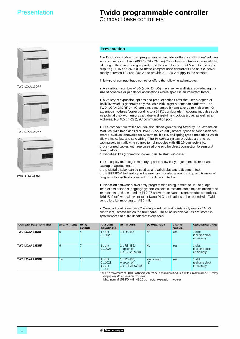
The Twido range of compact programmable controllers offers an "all-in-one" solution in a compact overall size (80/95 x 90 x 70 mm).Three base controllers are available, differing in their processing capacity and their number of c 24 V inputs and relay outputs (10, 16 and 24 I/O). All these compact base controllers use an a.c. power supply between 100 and 240 V and provide a c 24 V supply to the sensors.
This type of compact base controller offers the following advantages:
b A significant number of I/O (up to 24 I/O) in a small overall size, so reducing the size of consoles or panels for applications where space is an important factor.
b A variety of expansion options and product options offer the user a degree of flexibility which is generally only available with larger automation platforms. The TWD LCAA 24DRF 24 I/O compact base controller can take up to 4 discrete I/O expansion modules (corresponding to a 64 I/O configuration), optional modules such as a digital display, memory cartridge and real-time clock cartridge, as well as an additional RS 485 or RS 232C communication port.
b The compact controller solution also allows great wiring flexibility. For expansion modules (with base controller TWD LCAA 24DRF) several types of connection are offered, such as removable screw terminal blocks, and spring type connections which allow simple, fast and safe wiring. The TwidoFast system provides a pre-wired cabling solution, allowing connection of modules with HE 10 connectors to:v pre-formed cables with free wires at one end for direct connection to sensors/preactuators,v TwidoFast kits (connection cables plus Telefast sub-base).
b The display and plug-in memory options allow easy adjustment, transfer and backup of applications: v the digital display can be used as a local display and adjustment tool,v the EEPROM technology in the memory modules allows backup and transfer of programs to any Twido compact or modular controller.
b TwidoSoft software allows easy programming using instruction list language instructions or ladder language graphic objects. It uses the same objects and sets of instructions as those used by PL7-07 software for Nano programmable controllers. TwidoSoft software allows existing Nano PLC applications to be reused with Twido controllers by importing an ASCII file.
b Compact controllers have 2 analogue adjustment points (only one for 10 I/O controllers) accessible on the front panel. These adjustable values are stored in system words and are updated at every scan.
Presentation
TWD LCAA 10DRF
TWD LCAA 16DRF
TWD LCAA 24DRF
Compact base controller c 24V inputs Relayoutputs
Analogue adjustment
Serial ports I/O expansion Display module
Optional cartridge
TWD LCAA 10DRF 6 4 1 point 0…1023
1 x RS 485 No Yes 1 slot: real-time clock or memory
TWD LCAA 16DRF 9 7 1 point 0…1023
1 x RS 485,+ option of 1 x RS 232C/485
No Yes 1 slot: real-time clock or memory
TWD LCAA 24DRF 14 10 1 point 0…10231 point 0…511
1 x RS 485,+ option of 1 x RS 232C/485
Yes, 4 max(1)
Yes 1 slot: real-time clock or memory
(1) I.e.: a maximum of 88 I/O with screw terminal expansion modules, with a maximum of 32 relay outputs in I/O expansion modules. Maximum of 152 I/O with HE 10 connector expansion modules.
5
Description 0 Twido programmable controller 0
Compact base controllers
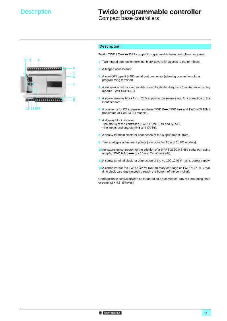
Twido TWD LCAA pp DRF compact programmable base controllers comprise:
1 Two hinged connection terminal block covers for access to the terminals.
2 A hinged access door.
3 A mini-DIN type RS 485 serial port connector (allowing connection of the programming terminal).
4 A slot (protected by a removable cover) for digital diagnostic/maintenance display module TWD XCP ODC.
5 A screw terminal block for c 24 V supply to the sensors and for connection of the input sensors.
6 A connector for I/O expansion modules TWD Dpp, TWD App and TWD NOI 10M3 (maximum of 4 on 24 I/O models).
7 A display block showing:- the status of the controller (PWR, RUN, ERR and STAT),- the inputs and outputs (INp and OUTp).
8 A screw terminal block for connection of the output preactuators.
9 Two analogue adjustment points (one point for 10 and 16 I/O models).
10 An extension connector for the addition of a 2nd RS 232C/RS 485 serial port using adapter TWD NAC ppp (for 16 and 24 I/O models).
11 A screw terminal block for connection of the a 100...240 V mains power supply
12 A connector for the TWD XCP MFK32 memory cartridge or TWD XCP RTC real-time clock cartridge (access through the bottom of the controller).
Compact base controllers can be mounted on a symmetrical DIN rail, mounting plate or panel (2 x 4.3 Ø holes).
Description
1
2 3 4
5
6
7
8
9101112
1
6
Characteristics 0 Twido programmable controller 0
Compact base controllers
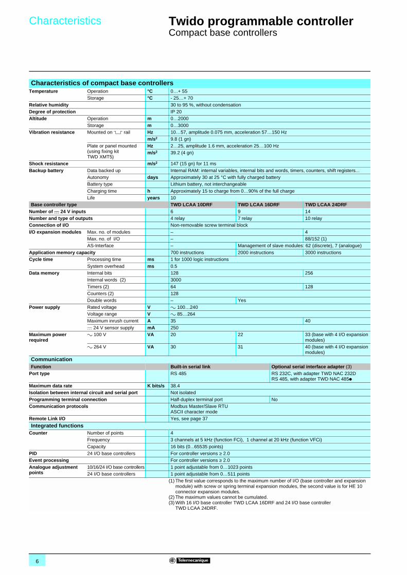
Characteristics of compact base controllersTemperature Operation °C 0…+ 55
Storage °C - 25…+ 70
Relative humidity 30 to 95 %, without condensationDegree of protection IP 20Altitude Operation m 0…2000
Storage m 0…3000Vibration resistance Mounted on 5 rail Hz 10…57, amplitude 0.075 mm, acceleration 57…150 Hz
m/s2 9.8 (1 gn)
Plate or panel mounted (using fixing kit TWD XMT5)
Hz 2…25, amplitude 1.6 mm, acceleration 25…100 Hzm/s2 39.2 (4 gn)
Shock resistance m/s2 147 (15 gn) for 11 ms
Backup battery Data backed up Internal RAM: internal variables, internal bits and words, timers, counters, shift registers...Autonomy days Approximately 30 at 25 °C with fully charged batteryBattery type Lithium battery, not interchangeable
Charging time h Approximately 15 to charge from 0…90% of the full chargeLife years 10
Base controller type TWD LCAA 10DRF TWD LCAA 16DRF TWD LCAA 24DRFNumber of c 24 V inputs 6 9 14Number and type of outputs 4 relay 7 relay 10 relayConnection of I/O Non-removable screw terminal block
I/O expansion modules Max. no. of modules – 4Max. no. of I/O – 88/152 (1)AS-Interface – Management of slave modules: 62 (discrete), 7 (analogue)
Application memory capacity 700 instructions 2000 instructions 3000 instructionsCycle time Processing time ms 1 for 1000 logic instructions
System overhead ms 0.5Data memory Internal bits 128 256
Internal words (2) 3000
Timers (2) 64 128Counters (2) 128Double words – Yes
Power supply Rated voltage V a 100…240Voltage range V a 85…264Maximum inrush current A 35 40
c 24 V sensor supply mA 250Maximum power required
a 100 V VA 20 22 33 (base with 4 I/O expansion modules)
a 264 V VA 30 31 40 (base with 4 I/O expansion modules)
CommunicationFunction Built-in serial link Optional serial interface adapter (3)
Port type RS 485 RS 232C, with adapter TWD NAC 232DRS 485, with adapter TWD NAC 485p
Maximum data rate K bits/s 38.4Isolation between internal circuit and serial port Not isolated
Programming terminal connection Half-duplex terminal port NoCommunication protocols Modbus Master/Slave RTU
ASCII character modeRemote Link I/O Yes, see page 37
Integrated functionsCounter Number of points 4
Frequency 3 channels at 5 kHz (function FCi), 1 channel at 20 kHz (function VFCi)
Capacity 16 bits (0...65535 points)PID 24 I/O base controllers For controller versions ≥ 2.0Event processing For controller versions ≥ 2.0
Analogue adjustment points
10/16/24 I/O base controllers 1 point adjustable from 0…1023 points24 I/O base controllers 1 point adjustable from 0…511 points
(1) The first value corresponds to the maximum number of I/O (base controller and expansion module) with screw or spring terminal expansion modules, the second value is for HE 10 connector expansion modules.
(2) The maximum values cannot be cumulated.(3) With 16 I/O base controller TWD LCAA 16DRF and 24 I/O base controller
TWD LCAA 24DRF.
7
Characteristics (continued) 0 Twido programmable controller 0
Compact base controllers
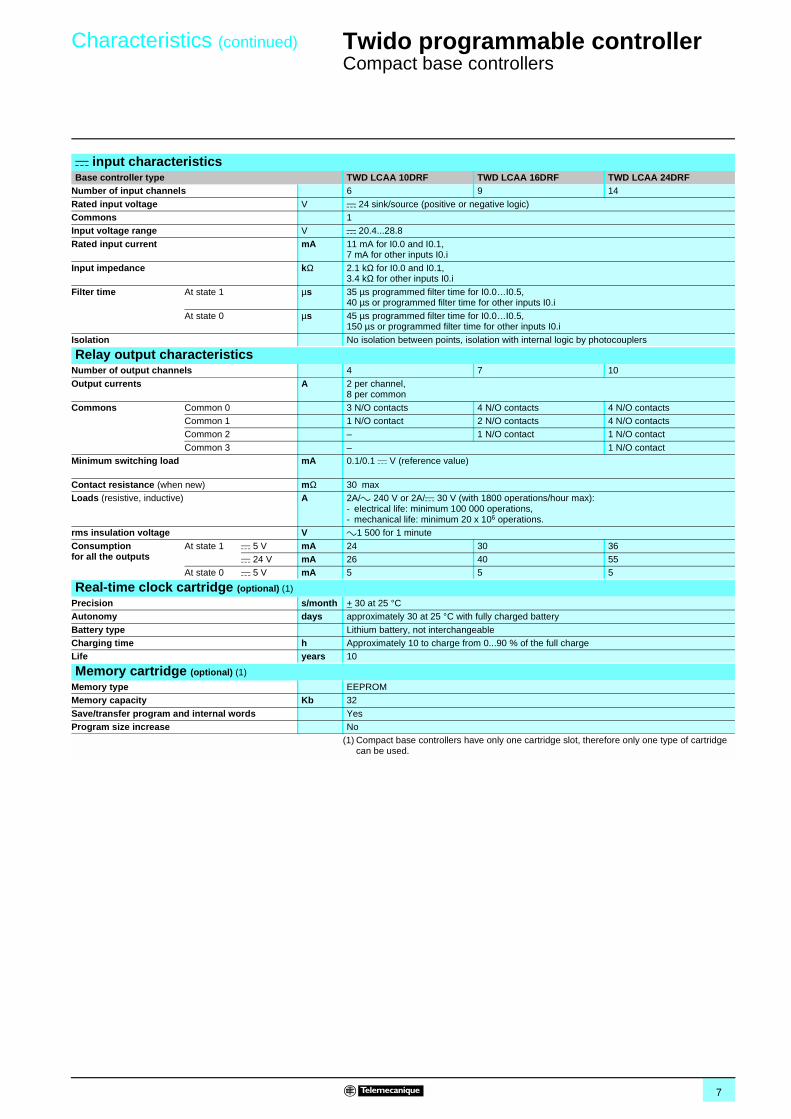
c input characteristics Base controller type TWD LCAA 10DRF TWD LCAA 16DRF TWD LCAA 24DRF
Number of input channels 6 9 14
Rated input voltage V c 24 sink/source (positive or negative logic)Commons 1Input voltage range V c 20.4...28.8
Rated input current mA 11 mA for I0.0 and I0.1, 7 mA for other inputs I0.i
Input impedance kΩ 2.1 kΩ for I0.0 and I0.1, 3.4 kΩ for other inputs I0.i
Filter time At state 1 µs 35 µs programmed filter time for I0.0…I0.5,40 µs or programmed filter time for other inputs I0.i
At state 0 µs 45 µs programmed filter time for I0.0…I0.5,150 µs or programmed filter time for other inputs I0.i
Isolation No isolation between points, isolation with internal logic by photocouplers
Relay output characteristicsNumber of output channels 4 7 10
Output currents A 2 per channel,8 per common
Commons Common 0 3 N/O contacts 4 N/O contacts 4 N/O contactsCommon 1 1 N/O contact 2 N/O contacts 4 N/O contactsCommon 2 – 1 N/O contact 1 N/O contact
Common 3 – 1 N/O contactMinimum switching load mA 0.1/0.1 c V (reference value)
Contact resistance (when new) mΩ 30 maxLoads (resistive, inductive) A 2A/a 240 V or 2A/c 30 V (with 1800 operations/hour max):
- electrical life: minimum 100 000 operations,- mechanical life: minimum 20 x 106 operations.
rms insulation voltage V a1 500 for 1 minute
Consumptionfor all the outputs
At state 1 c 5 V mA 24 30 36c 24 V mA 26 40 55
At state 0 c 5 V mA 5 5 5
Real-time clock cartridge (optional) (1)
Precision s/month + 30 at 25 °CAutonomy days approximately 30 at 25 °C with fully charged battery
Battery type Lithium battery, not interchangeableCharging time h Approximately 10 to charge from 0...90 % of the full chargeLife years 10
Memory cartridge (optional) (1)
Memory type EEPROMMemory capacity Kb 32
Save/transfer program and internal words YesProgram size increase No
(1) Compact base controllers have only one cartridge slot, therefore only one type of cartridge can be used.
8
References 0 Twido programmable controller 0
Compact base controllers
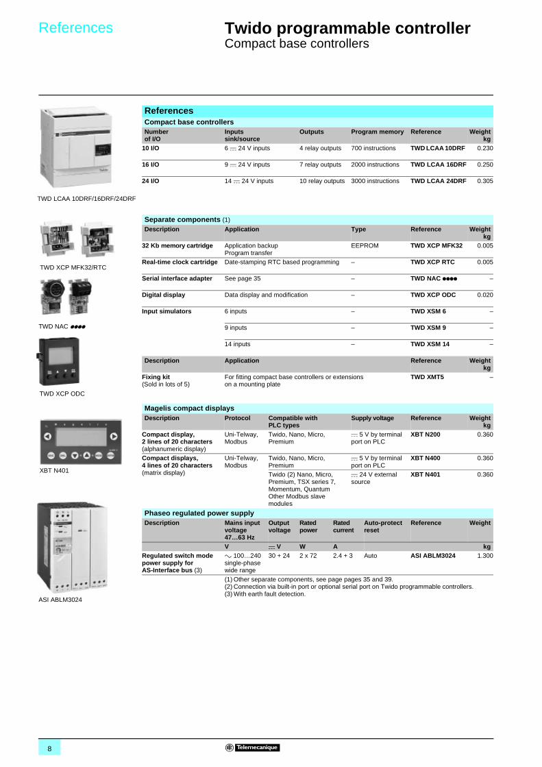
ReferencesCompact base controllersNumber of I/O
Inputssink/source
Outputs Program memory Reference Weightkg
10 I/O 6 c 24 V inputs 4 relay outputs 700 instructions TWD LCAA 10DRF 0.230
16 I/O 9 c 24 V inputs 7 relay outputs 2000 instructions TWD LCAA 16DRF 0.250
24 I/O 14 c 24 V inputs 10 relay outputs 3000 instructions TWD LCAA 24DRF 0.305
Separate components (1)
Description Application Type Reference Weightkg
32 Kb memory cartridge Application backupProgram transfer
EEPROM TWD XCP MFK32 0.005
Real-time clock cartridge Date-stamping RTC based programming –
TWD XCP RTC 0.005
Serial interface adapter See page 35 –
TWD NAC pppp –
Digital display Data display and modification –
TWD XCP ODC 0.020
Input simulators 6 inputs –
TWD XSM 6 –
9 inputs –
TWD XSM 9 –
14 inputs – TWD XSM 14 –
Description Application Reference Weightkg
Fixing kit(Sold in lots of 5)
For fitting compact base controllers or extensions on a mounting plate
TWD XMT5 –
Magelis compact displaysDescription Protocol Compatible with
PLC typesSupply voltage Reference Weight
kgCompact display, 2 lines of 20 characters(alphanumeric display)
Uni-Telway, Modbus
Twido, Nano, Micro, Premium
c 5 V by terminal port on PLC
XBT N200 0.360
Compact displays, 4 lines of 20 characters(matrix display)
Uni-Telway, Modbus
Twido, Nano, Micro, Premium
c 5 V by terminal port on PLC
XBT N400 0.360
Twido (2) Nano, Micro, Premium, TSX series 7, Momentum, Quantum Other Modbus slave modules
c 24 V external source
XBT N401 0.360
Phaseo regulated power supplyDescription Mains input
voltage 47…63 Hz
Output voltage
Rated power
Rated current
Auto-protect reset
Reference Weight
V c V W A kgRegulated switch mode power supply for AS-Interface bus (3)
a 100…240 single-phase wide range
30 + 24 2 x 72 2.4 + 3 Auto ASI ABLM3024 1.300
(1) Other separate components, see page pages 35 and 39.(2) Connection via built-in port or optional serial port on Twido programmable controllers.(3) With earth fault detection.
TWD LCAA 10DRF/16DRF/24DRF
TWD XCP MFK32/RTC
TWD NAC pppp
TWD XCP ODC
XBT N401
ASI ABLM3024
9
Dimensions,connections 0
Twido programmable controller 0
Compact base controllers
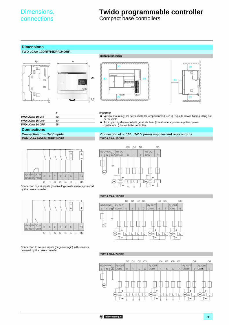
DimensionsTWD LCAA 10DRF/16DRF/24DRF
Installation rules
a Important:b Vertical mounting: not permissible for temperatures u 40° C, “upside down” flat mounting not
permissible.b Avoid placing devices which generate heat (transformers, power supplies, power
contactors...) beneath the controller.
TWD LCAA 10 DRF 80TWD LCAA 16 DRF 80TWD LCAA 24 DRF 95
ConnectionsConnection of c 24 V inputs Connection of a 100…240 V power supplies and relay outputs TWD LCAA 10DRF/16DRF/24DRF TWD LCAA 10DRF
Connection to sink inputs (positive logic) with sensors powered by the base controller.
TWD LCAA 16DRF
Connection to source inputs (negative logic) with sensors powered by the base controller.
70 a
90
4,5
20
4040
20
80
20
20
TWD LCAA 24DRF
10
Presentation 0 Twido programmable controller 0
Modular base controllers
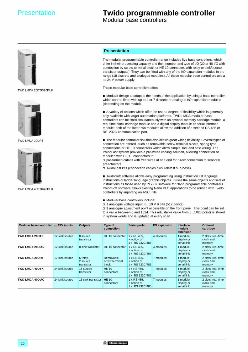
The modular programmable controller range includes five base controllers, which differ in their processing capacity and their number and type of I/O (20 or 40 I/O with connection by screw terminal block or HE 10 connector, with relay or sink/source transistor outputs). They can be fitted with any of the I/O expansion modules in the range (18 discrete and analogue modules). All these modular base controllers use a c 24 V power supply.
These modular base controllers offer:
b Modular design to adapt to the needs of the application by using a base controller which can be fitted with up to 4 or 7 discrete or analogue I/O expansion modules (depending on the model).
b A variety of options which offer the user a degree of flexibility which is generally only available with larger automation platforms. TWD LMDA modular base controllers can be fitted simultaneously with an optional memory cartridge module, a real-time clock cartridge module and a digital display module or serial interface module; both of the latter two modules allow the addition of a second RS 485 or RS 232C communication port.
b The modular controller solution also allows great wiring flexibility. Several types of connection are offered, such as removable screw terminal blocks, spring type connections or HE 10 connectors which allow simple, fast and safe wiring. The TwidoFast system provides a pre-wired cabling solution, allowing connection of modules with HE 10 connectors to:v pre-formed cables with free wires at one end for direct connection to sensors/preactuators,v TwidoFast kits (connection cables plus Telefast sub-base).
b TwidoSoft software allows easy programming using instruction list language instructions or ladder language graphic objects. It uses the same objects and sets of instructions as those used by PL7-07 software for Nano programmable controllers. TwidoSoft software allows existing Nano PLC applications to be reused with Twido controllers by importing an ASCII file.
b Modular base controllers include:v 1 analogue voltage input, 0...10 V 9 bits (512 points),v 1 analogue adjustment point accessible on the front panel. This point can be set to a value between 0 and 1024. This adjustable value from 0...1023 points is stored in system words and is updated at every scan.
Presentation
TWD LMDA 20DTK/20DUK
TWD LMDA 20DRT
TWD LMDA 40DTK/40DUK
Modular base controller c 24V inputs Outputs Type of connection
Serial ports I/O expansion Interface module extension
Optional cartridge
TWD LMDA 20DTK 12 sink/source 8 source transistor
HE 10 connector 1 x RS 485,+ option of 1 x RS 232C/485
4 modules 1 module: display or serial link
2 slots: real-time clock and memory
TWD LMDA 20DUK 12 sink/source 8 sink transistor HE 10 connector 1 x RS 485,+ option of 1 x RS 232C/485
4 modules 1 module: display or serial link
2 slots: real-time clock and memory
TWD LMDA 20DRT 12 sink/source 6 relay,2 source transistor
Removable screw terminal block
1 x RS 485,+ option of 1 x RS 232C/485
7 modules 1 module: display orserial link
2 slots: real-time clock and memory
TWD LMDA 40DTK 24 sink/source 16 source transistor
HE 10 connectors
1 x RS 485,+ option of 1 x RS 232C/485
7 modules 1 module: display or serial link
2 slots: real-time clock and memory
TWD LMDA 40DUK 24 sink/source 16 sink transistor HE 10 connectors
1 x RS 485,+ option of 1 x RS 232C/485
7 modules 1 module: display or serial link
2 slots: real-time clock and memory
11
Description 0 Twido programmable controller 0
Modular base controllers
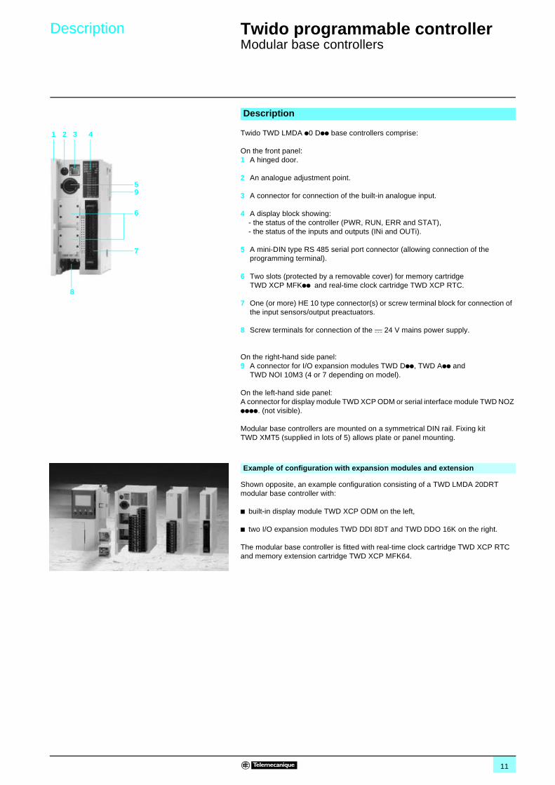
Twido TWD LMDA p0 Dpp base controllers comprise:
On the front panel: 1 A hinged door.
2 An analogue adjustment point.
3 A connector for connection of the built-in analogue input.
4 A display block showing:- the status of the controller (PWR, RUN, ERR and STAT),- the status of the inputs and outputs (INi and OUTi).
5 A mini-DIN type RS 485 serial port connector (allowing connection of the programming terminal).
6 Two slots (protected by a removable cover) for memory cartridge TWD XCP MFKpp and real-time clock cartridge TWD XCP RTC.
7 One (or more) HE 10 type connector(s) or screw terminal block for connection of the input sensors/output preactuators.
8 Screw terminals for connection of the c 24 V mains power supply.
On the right-hand side panel:9 A connector for I/O expansion modules TWD Dpp, TWD App and
TWD NOI 10M3 (4 or 7 depending on model).
On the left-hand side panel:A connector for display module TWD XCP ODM or serial interface module TWD NOZ pppp. (not visible).
Modular base controllers are mounted on a symmetrical DIN rail. Fixing kit TWD XMT5 (supplied in lots of 5) allows plate or panel mounting.
Shown opposite, an example configuration consisting of a TWD LMDA 20DRT modular base controller with:
b built-in display module TWD XCP ODM on the left,
b two I/O expansion modules TWD DDI 8DT and TWD DDO 16K on the right.
The modular base controller is fitted with real-time clock cartridge TWD XCP RTC and memory extension cartridge TWD XCP MFK64.
Description
1 2 3 4
5
6
7
8
9
Example of configuration with expansion modules and extension
12
Characteristics 0 Twido programmable controller 0
Modular base controllers
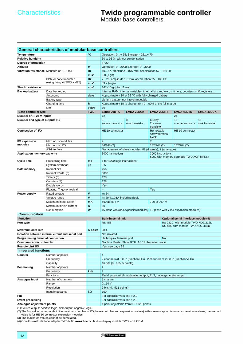
General characteristics of modular base controllersTemperature °C Operation: 0…+ 55; Storage: - 25…+ 70Relative humidity 30 to 95 %, without condensation
Degree of protection IP 20Altitude m Operation: 0…2000; Storage: 0…3000Vibration resistance Mounted on 5 rail Hz 10…57, amplitude 0.075 mm, acceleration 57…150 Hz
m/s2 9.8 (1 gn)Plate or panel mounted (using fixing kit TWD XMT5)
Hz 2…25, amplitude 1.6 mm, acceleration 25…100 Hzm/s2 39.2 (4 gn)
Shock resistance m/s2 147 (15 gn) for 11 msBackup battery Data backed up Internal RAM: internal variables, internal bits and words, timers, counters, shift registers...
Autonomy days Approximately 30 at 25 °C with fully charged battery
Battery type Lithium battery, not interchangeableCharging time h Approximately 15 to charge from 0…90% of the full chargeLife years 10
Base controller type TWD LMDA 20DTK LMDA 20DUK LMDA 20DRT LMDA 40DTK LMDA 40DUKNumber of c 24 V inputs 12 24Number and type of outputs (1) 8
source transistor8 sink transistor
6 relay,2 source transistor
16source transistor
16 sink transistor
Connection of I/O HE 10 connector Removable screw terminal block
HE 10 connector
I/O expansion modules
Max. no. of modules 4 7Max. no. of I/O 84/148 (2) 132/244 (2) 152/264 (2)AS-Interface Management of slave modules: 62 (discrete), 7 (analogue)
Application memory capacity 3000 instructions 3000 instructions,6000 with memory cartridge TWD XCP MFK64
Cycle time Processing time ms 1 for 1000 logic instructionsSystem overhead µs 0.5
Data memory Internal bits 256Internal words (3) 3000Timers (3) 128
Counters (3) 128Double words YesFloating, Trigonometrical – Yes
Power supply Rated voltage V c 24Voltage range V c 20.4…26.4 including rippleMaximum input current mA 560 at 26.4 V 700 at 26.4 V
Maximum inrush current A 50Consumption W 15 (base with 4 I/O expansion modules) 19 (base with 7 I/O expansion modules)
CommunicationFunction Built-in serial link Optional serial interface module (4)
Port type RS 485 RS 232C, with module TWD NOZ 232DRS 485, with module TWD NOZ 485p
Maximum data rate K bits/s 38.4
Isolation between internal circuit and serial port Not isolatedProgramming terminal connection Half-duplex terminal port NoCommunication protocols Modbus Master/Slave RTU. ASCII character mode
Remote Link I/O Yes, see page 35
Integrated functionsCounter Number of points 4
Frequency 2 channels at 5 kHz (function FCi), 2 channels at 20 kHz (function VFCi)Capacity 16 bits (0...65535 points)
Positioning Number of points 2Frequency kHz 7Functions PWM, pulse width modulation output; PLS, pulse generator output
Analogue input Number of channels 1 channelRange 0...10 VResolution 9 bits (0...511 points)
Input impedance kΩ 100PID For controller versions ≥ 2.0Event processing For controller versions ≥ 2.0
Analogue adjustment points 1 point adjustable from 0…1023 points(1) Source output: positive logic, sink output: negative logic.(2) The first value corresponds to the maximum number of I/O (base controller and expansion module) with screw or spring terminal expansion modules, the second
value is for HE 10 connector expansion modules.(3) The maximum values cannot be cumulated.(4) Or with serial interface adapter TWD NAC pppp fitted in built-in display module TWD XCP ODM.
13
Characteristics (continued) 0 Twido programmable controller 0
Modular base controllers
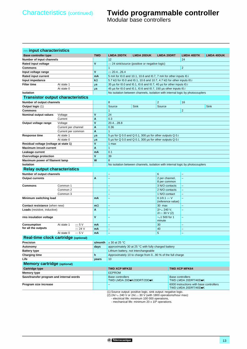
c input characteristics Base controller type TWD LMDA 20DTK LMDA 20DUK LMDA 20DRT LMDA 40DTK LMDA 40DUK
Number of input channels 12 24
Rated input voltage V c 24 sink/source (positive or negative logic)Commons 1 2Input voltage range V c 20.4...26.4
Rated input current mA 5 mA for I0.0 and 10.1, 10.6 and I0.7, 7 mA for other inputs I0.iInput impedance kΩ 5.7 kΩ for I0.0 and I0.1, 10.6 and 10.7, 4.7 kΩ for other inputs I0.iFilter time At state 1 µs 35 µs for I0.0 and I0.1, I0.6 and I0.7, 40 µs for other inputs I0.i
At state 0 µs 45 µs for I0.0 and I0.1, I0.6 and I0.7, 150 µs other inputs I0.iIsolation No isolation between channels, isolation with internal logic by photocouplers
Transistor output characteristicsNumber of output channels 8 2 16Output logic (1) Source Sink Source SinkCommons 1 2
Nominal output values Voltage V 24Current A 0.3
Output voltage range Voltage V 20.4…28.8
Current per channel A 0.36Current per common A 1
Response time At state 1 µs 5 µs for Q 0.0 and Q 0.1, 300 µs for other outputs Q 0.i
At state 0 µs 5 µs for Q 0.0 and Q 0.1, 300 µs for other outputs Q 0.iResidual voltage (voltage at state 1) V 1 maxMaximum inrush current A 1
Leakage current mA 0.1Overvoltage protection V 39
Maximum power of filament lamp W 8Isolation No isolation between channels, isolation with internal logic by photocouplers
Relay output characteristicsNumber of output channels – 6 –Output currents A – 2 per channel,
8 per common–
Commons Common 1 – 3 N/O contacts –Common 2 – 2 N/O contacts –
Common 3 – 1 N/O contact –Minimum switching load mA – 0.1/0.1 c V
(reference value)–
Contact resistance (when new) mΩ – 30 max –Loads (resistive, inductive) A – 2/a 240 V,
2/c 30 V (2)–
rms insulation voltage V – a1 500 for 1 minute
–
Consumption for all the outputs
At state 1 c 5 V mA – 30 –
c 24 V mA – 40 –At state 0 c 5 V mA – 5 –
Real-time clock cartridge (optional)
Precision s/month + 30 at 25 °CAutonomy days approximately 30 at 25 °C with fully charged batteryBattery type Lithium battery, not interchangeable
Charging time h Approximately 10 to charge from 0...90 % of the full chargeLife years 10
Memory cartridge (optional)
Cartridge type TWD XCP MFK32 TWD XCP MFK64Memory type EEPROMSave/transfer program and internal words Base controllers
TWD LMDA 20DpK/20DRT/20DpKBase controllers TWD LMDA 20DRT/40DpK
Program size increase – 6000 instructions with base controllersTWD LMDA 20DRT/40DpK
(1) Source output: positive logic, sink output: negative logic.(2) 2A/a 240 V or 2A/c 30 V (with 1800 operations/hour max):
- electrical life: minimum 100 000 operations,- mechanical life: minimum 20 x 106 operations.
14
References 0 Twido programmable controller 0
Modular base controllers
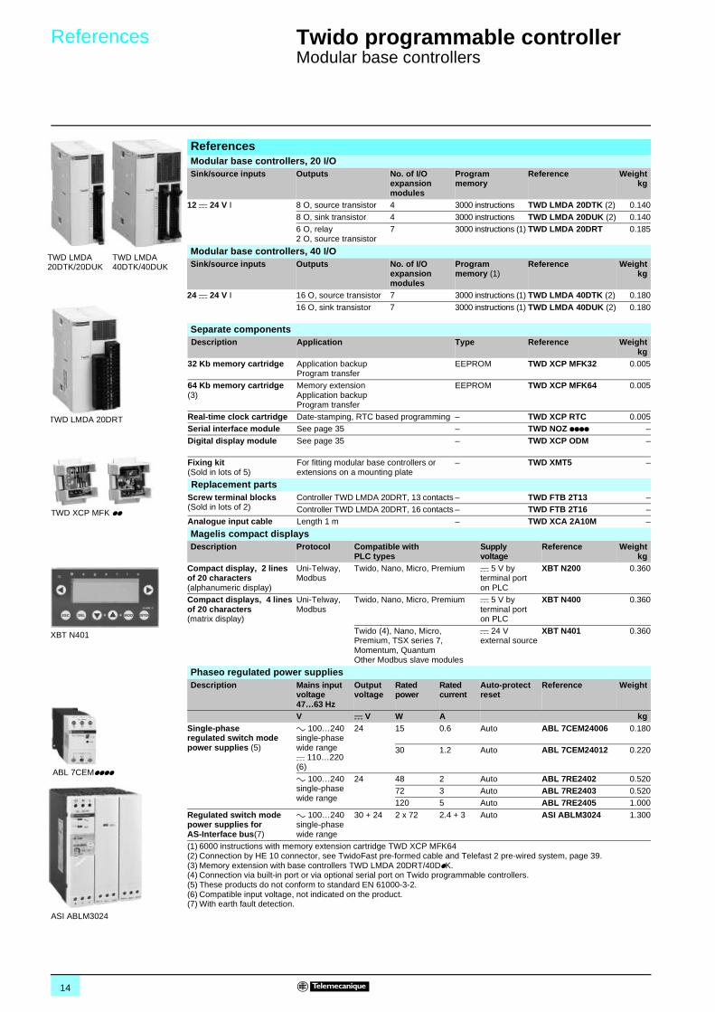
ReferencesModular base controllers, 20 I/OSink/source inputs Outputs No. of I/O
expansion modules
Programmemory
Reference Weightkg
12 c 24 V I 8 O, source transistor 4 3000 instructions TWD LMDA 20DTK (2) 0.140
8 O, sink transistor 4 3000 instructions TWD LMDA 20DUK (2) 0.1406 O, relay2 O, source transistor
7 3000 instructions (1) TWD LMDA 20DRT 0.185
Modular base controllers, 40 I/OSink/source inputs Outputs No. of I/O
expansion modules
Program memory (1)
Reference Weightkg
24 c 24 V I 16 O, source transistor 7 3000 instructions (1) TWD LMDA 40DTK (2) 0.180
16 O, sink transistor 7 3000 instructions (1) TWD LMDA 40DUK (2) 0.180
Separate components Description Application Type Reference Weight
kg32 Kb memory cartridge Application backup
Program transferEEPROM TWD XCP MFK32 0.005
64 Kb memory cartridge(3)
Memory extensionApplication backupProgram transfer
EEPROM TWD XCP MFK64 0.005
Real-time clock cartridge Date-stamping, RTC based programming – TWD XCP RTC 0.005Serial interface module See page 35 – TWD NOZ pppp –
Digital display module See page 35 – TWD XCP ODM –
Fixing kit(Sold in lots of 5)
For fitting modular base controllers or extensions on a mounting plate
– TWD XMT5 –
Replacement partsScrew terminal blocks(Sold in lots of 2)
Controller TWD LMDA 20DRT, 13 contacts – TWD FTB 2T13 –Controller TWD LMDA 20DRT, 16 contacts – TWD FTB 2T16 –
Analogue input cable Length 1 m – TWD XCA 2A10M –
Magelis compact displaysDescription Protocol Compatible with
PLC typesSupply voltage
Reference Weightkg
Compact display, 2 lines of 20 characters(alphanumeric display)
Uni-Telway, Modbus
Twido, Nano, Micro, Premium c 5 V by terminal port on PLC
XBT N200 0.360
Compact displays, 4 lines of 20 characters(matrix display)
Uni-Telway, Modbus
Twido, Nano, Micro, Premium c 5 V by terminal port on PLC
XBT N400 0.360
Twido (4), Nano, Micro, Premium, TSX series 7, Momentum, Quantum Other Modbus slave modules
c 24 V external source
XBT N401 0.360
Phaseo regulated power suppliesDescription Mains input
voltage 47…63 Hz
Output voltage
Rated power
Rated current
Auto-protect reset
Reference Weight
V c V W A kgSingle-phaseregulated switch mode power supplies (5)
a 100…240 single-phase wide range c 110…220 (6)
24 15 0.6 Auto ABL 7CEM24006 0.180
30 1.2 Auto ABL 7CEM24012 0.220
a 100…240 single-phase wide range
24 48 2 Auto ABL 7RE2402 0.52072 3 Auto ABL 7RE2403 0.520120 5 Auto ABL 7RE2405 1.000
Regulated switch mode power supplies for AS-Interface bus(7)
a 100…240 single-phase wide range
30 + 24 2 x 72 2.4 + 3 Auto ASI ABLM3024 1.300
(1) 6000 instructions with memory extension cartridge TWD XCP MFK64(2) Connection by HE 10 connector, see TwidoFast pre-formed cable and Telefast 2 pre-wired system, page 39.(3) Memory extension with base controllers TWD LMDA 20DRT/40DpK.(4) Connection via built-in port or via optional serial port on Twido programmable controllers.(5) These products do not conform to standard EN 61000-3-2.(6) Compatible input voltage, not indicated on the product.(7) With earth fault detection.
TWD LMDA20DTK/20DUK
TWD LMDA40DTK/40DUK
TWD LMDA 20DRT
TWD XCP MFK pp
XBT N401
ABL 7CEMpppp
ASI ABLM3024
15
Dimensions,connections 0
Twido programmable controller 0
Modular base controllers
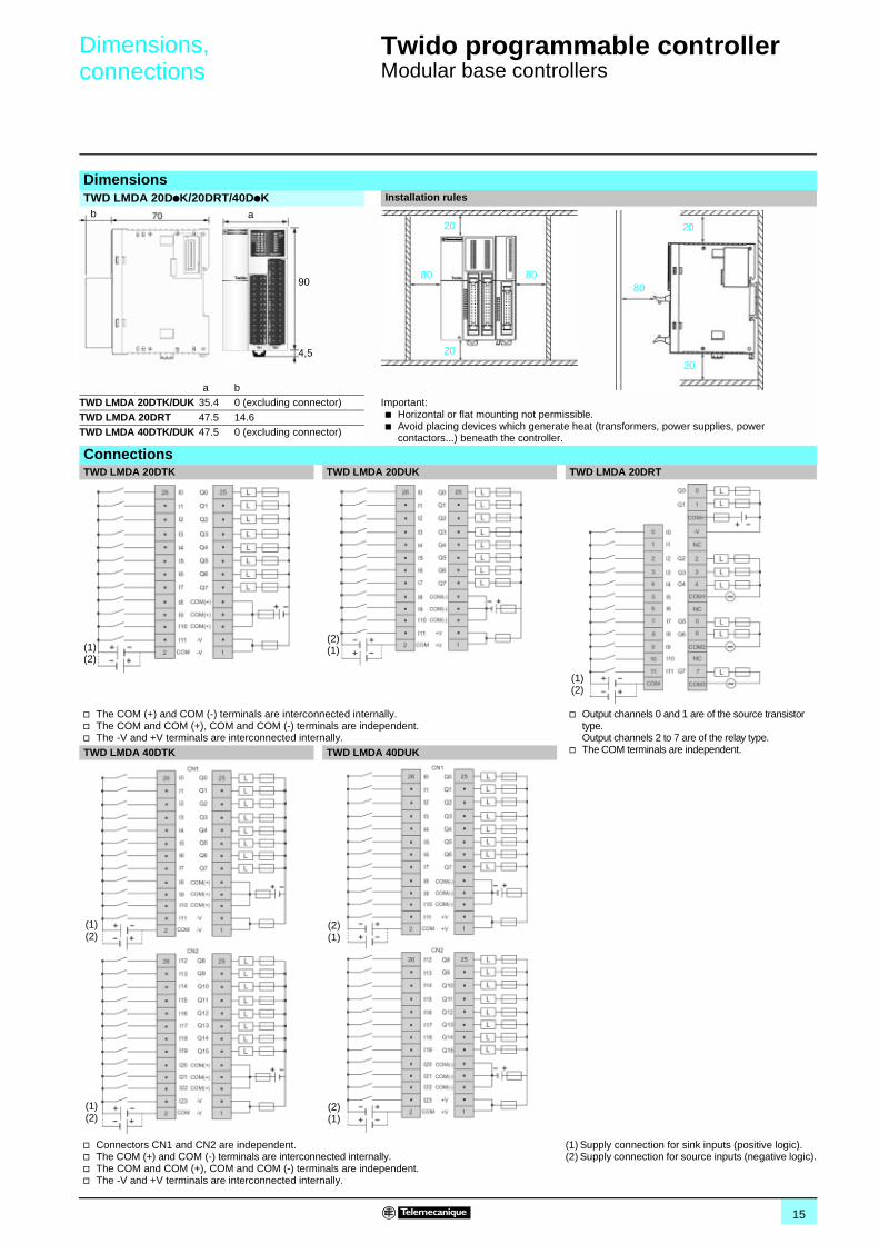
DimensionsTWD LMDA 20DpK/20DRT/40DpK Installation rules
a bTWD LMDA 20DTK/DUK 35.4 0 (excluding connector) Important:
b Horizontal or flat mounting not permissible.b Avoid placing devices which generate heat (transformers, power supplies, power
contactors...) beneath the controller.
TWD LMDA 20DRT 47.5 14.6 TWD LMDA 40DTK/DUK 47.5 0 (excluding connector)
ConnectionsTWD LMDA 20DTK TWD LMDA 20DUK TWD LMDA 20DRT
v The COM (+) and COM (-) terminals are interconnected internally.v The COM and COM (+), COM and COM (-) terminals are independent.v The -V and +V terminals are interconnected internally.
v Output channels 0 and 1 are of the source transistor type.Output channels 2 to 7 are of the relay type.
v The COM terminals are independent.TWD LMDA 40DTK TWD LMDA 40DUK
v Connectors CN1 and CN2 are independent.v The COM (+) and COM (-) terminals are interconnected internally.v The COM and COM (+), COM and COM (-) terminals are independent.v The -V and +V terminals are interconnected internally.
(1) Supply connection for sink inputs (positive logic).(2) Supply connection for source inputs (negative logic).
a
90
4,5
b20
20
8080
20
20
80
(1)(2)
(2)(1)
(1)(2)
(1)(2)
(1)(2)
(2)(1)
(2)(1)
16
Selection guide 0 Twido programmable controller 0
Discrete I/O modules
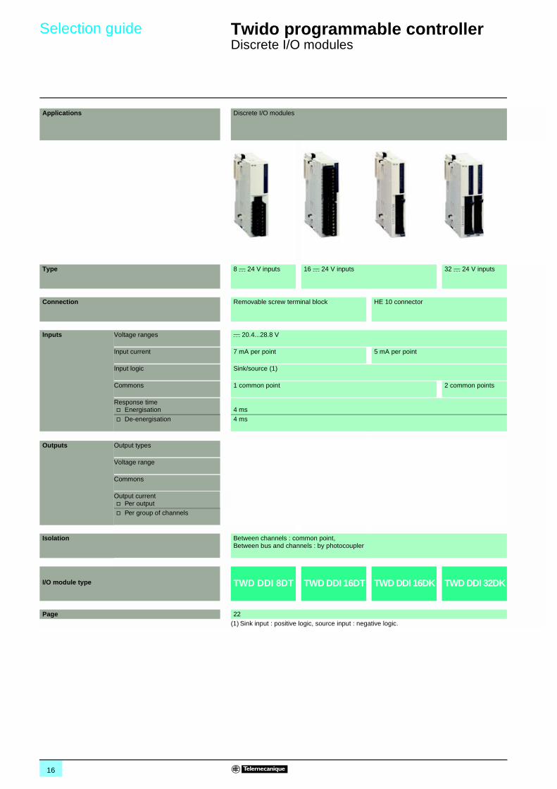
Applications Discrete I/O modules
Type 8 c 24 V inputs 16 c 24 V inputs 32 c 24 V inputs
Connection Removable screw terminal block HE 10 connector
Inputs Voltage ranges c 20.4...28.8 V
Input current 7 mA per point 5 mA per point
Input logic Sink/source (1)
Commons 1 common point 2 common points
Response timev Energisation 4 ms
v De-energisation 4 ms
Outputs Output types
Voltage range
Commons
Output currentv Per outputv Per group of channels
Isolation Between channels : common point, Between bus and channels : by photocoupler
I/O module type TWD DDI 8DT TWD DDI 16DT TWD DDI 16DK TWD DDI 32DK
Page 22(1) Sink input : positive logic, source input : negative logic.
17
00
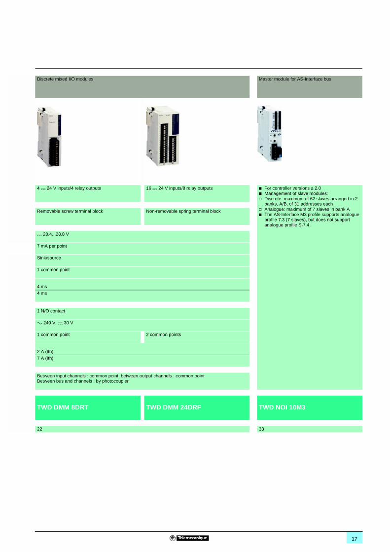
Discrete mixed I/O modules Master module for AS-Interface bus
4 c 24 V inputs/4 relay outputs 16 c 24 V inputs/8 relay outputs b For controller versions ≥ 2.0b Management of slave modules:v Discrete: maximum of 62 slaves arranged in 2
banks, A/B, of 31 addresses eachv Analogue: maximum of 7 slaves in bank Ab The AS-Interface M3 profile supports analogue
profile 7.3 (7 slaves), but does not support analogue profile S-7.4
Removable screw terminal block Non-removable spring terminal block
c 20.4...28.8 V
7 mA per point
Sink/source
1 common point
4 ms
4 ms
1 N/O contact
a 240 V, c 30 V
1 common point 2 common points
2 A (Ith)
7 A (Ith)
Between input channels : common point, between output channels : common pointBetween bus and channels : by photocoupler
TWD DMM 8DRT TWD DMM 24DRF TWD NOI 10M3
22 33
18
Selection guide (continued) 0 Twido programmable controller 0
Discrete I/O modules
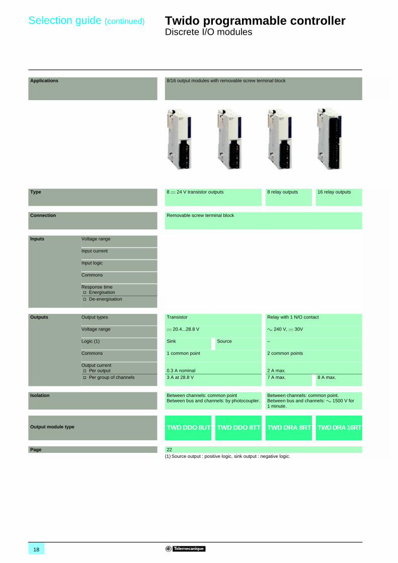
Applications 8/16 output modules with removable screw terminal block
Type 8 c 24 V transistor outputs 8 relay outputs 16 relay outputs
Connection Removable screw terminal block
Inputs Voltage range
Input current
Input logic
Commons
Response timev Energisation
v De-energisation
Outputs Output types Transistor Relay with 1 N/O contact
Voltage range c 20.4...28.8 V a 240 V, c 30V
Logic (1) Sink Source –
Commons 1 common point 2 common points
Output currentv Per output 0.3 A nominal 2 A max.
v Per group of channels 3 A at 28.8 V 7 A max. 8 A max.
Isolation Between channels: common pointBetween bus and channels: by photocoupler.
Between channels: common point. Between bus and channels: a 1500 V for1 minute.
Output module type TWD DDO 8UT TWD DDO 8TT TWD DRA 8RT TWD DRA 16RT
Page 22(1) Source output : positive logic, sink output : negative logic.
19
00
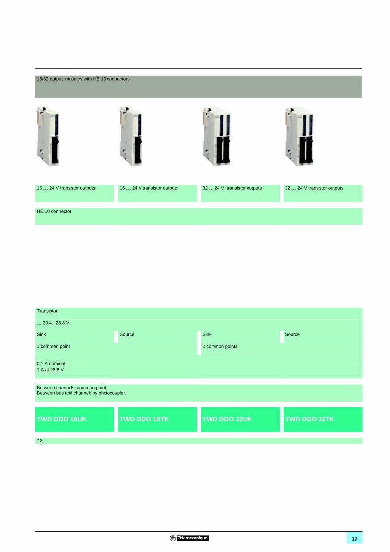
16/32 output modules with HE 10 connectors
16 c 24 V transistor outputs 16 c 24 V transistor outputs 32 c 24 V transistor outputs 32 c 24 V transistor outputs
HE 10 connector
Transistor
c 20.4...28.8 V
Sink Source Sink Source
1 common point 2 common points
0.1 A nominal
1 A at 28.8 V
Between channels: common point. Between bus and channel: by photocoupler.
TWD DDO 16UK TWD DDO 16TK TWD DDO 32UK TWD DDO 32TK
22
20
Presentation,description 0
Twido programmable controller 0
Discrete I/O modules
The range of Twido I/O modules includes input modules, output modules and mixed input/output modules. With the 14 I/O modules offered, in addition to the I/O integrated in 24 I/O compact base controllers and modular base controllers, configurations can be adapted to best suit application requirements, so optimising costs. The following discrete I/O modules are available :
b 4 c 24 V discrete input modules comprising an 8-channel module, two 16-channel modules and a 32-channel module, equipped with either removable screw terminal blocks or HE 10 type connector, depending on the model. These modules can be either “sink or source”.
b 8 discrete output modules comprising two output modules with 8 and 16 relay outputs, three output modules with 8, 16 or 32-channel "sink" transistor outputs and three output modules with 8, 16 or 32-channel "source" transistor outputs, equipped with either removable screw terminal blocks or HE 10 type connector, depending on the model.
b 2 discrete mixed input and output modules, comprising one 4-channel input/4-channel relay output module with removable screw terminal block and one 16-channel input/8-channel relay output module with non-removable spring terminal block.
The narrow width of these I/O modules (17.5 mm, 23.5 mm, 29.7 mm or 39.1 mm) makes it possible to build Twido configurations of up to 264 I/O with a minimal overall size of L 255.4 mm x H 90 mm x D 81.3 mm.
All these discrete I/O modules and the analogue I/O modules are connected to the base controller by stacking them on a DIN rail, starting from the right-hand side panel of the base controller, according to the following rules : v For the 24 I/O compact base controller TWD LCAA 24DRF: 4 modules max. (see characteristics page 6).v For 20 I/O modular base controllers TWD LMDA 20DpK: 4 modules max. (see characteristics page 13).v For 20 and 40 I/O base controllers TWD LMDA 20DRT/40DpK: 7 modules max. (see characteristics page 13).
All the discrete I/O modules are electrically isolated with the use of a photocoupler between the internal electronic circuit and the input/output channels.
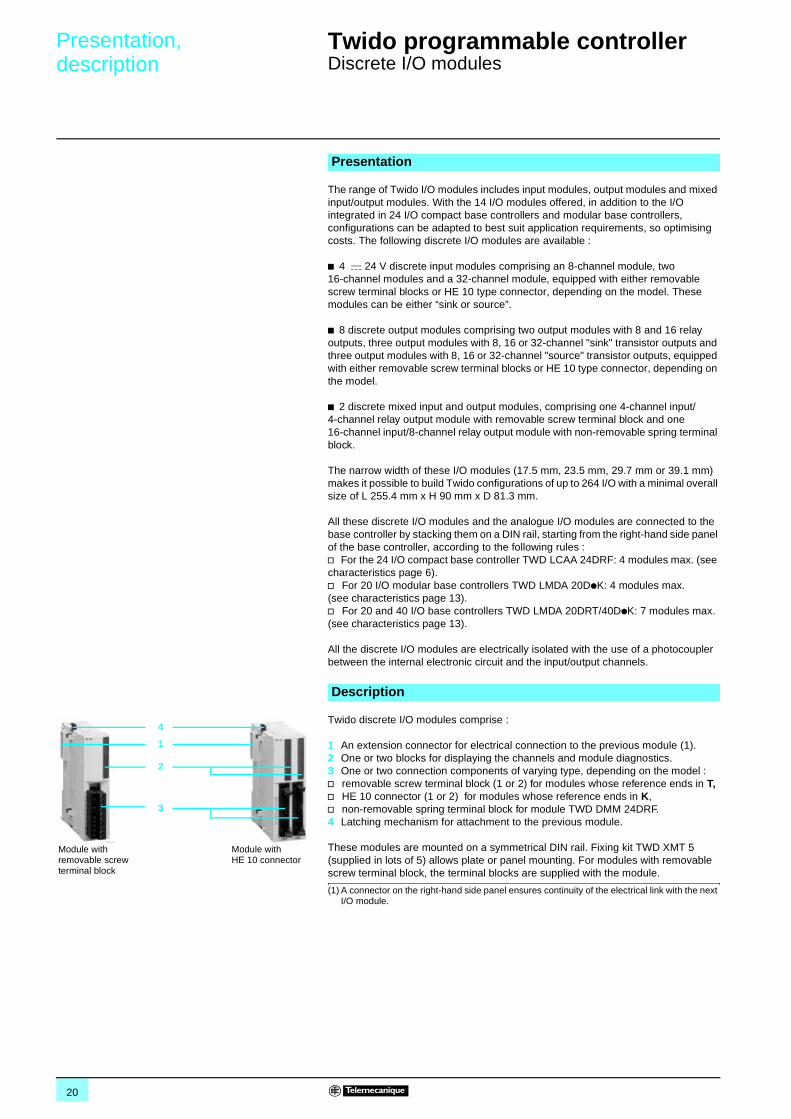
Twido discrete I/O modules comprise :
1 An extension connector for electrical connection to the previous module (1). 2 One or two blocks for displaying the channels and module diagnostics.3 One or two connection components of varying type, depending on the model :v removable screw terminal block (1 or 2) for modules whose reference ends in T,v HE 10 connector (1 or 2) for modules whose reference ends in K,v non-removable spring terminal block for module TWD DMM 24DRF.4 Latching mechanism for attachment to the previous module.
These modules are mounted on a symmetrical DIN rail. Fixing kit TWD XMT 5 (supplied in lots of 5) allows plate or panel mounting. For modules with removable screw terminal block, the terminal blocks are supplied with the module.
(1) A connector on the right-hand side panel ensures continuity of the electrical link with the next I/O module.
Presentation
Description
1
2
3
Module withHE 10 connector
Module with removable screw terminal block
4
21
Characteristics 0 Twido programmable controller 0
Discrete I/O modules
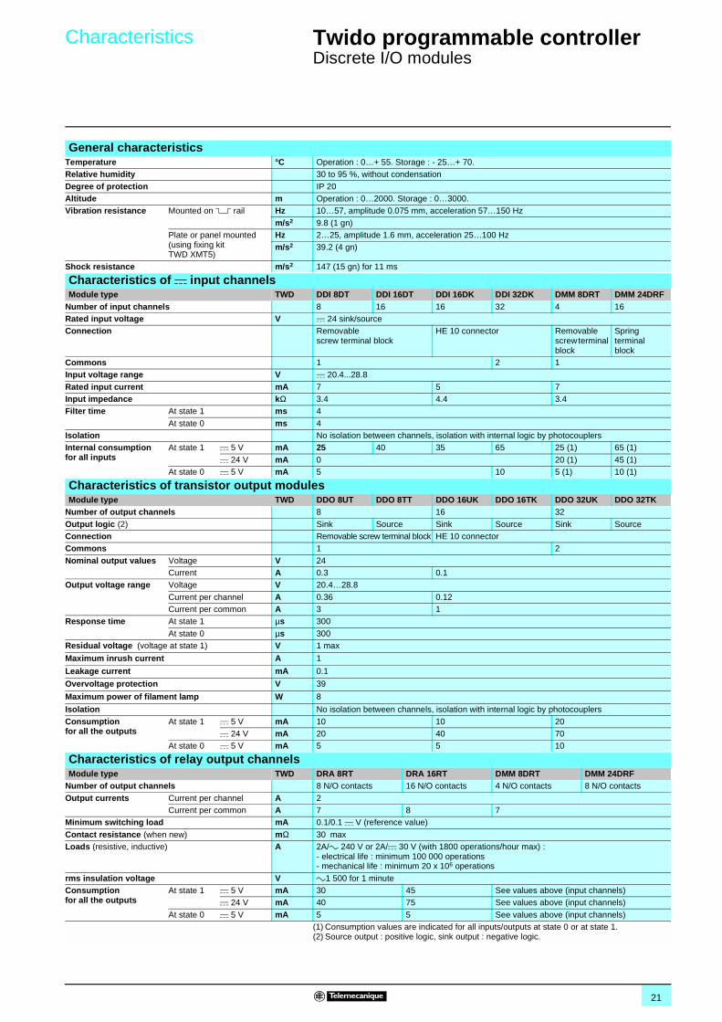
General characteristicsTemperature °C Operation : 0…+ 55. Storage : - 25…+ 70.Relative humidity 30 to 95 %, without condensation
Degree of protection IP 20Altitude m Operation : 0…2000. Storage : 0…3000.Vibration resistance Mounted on 5 rail Hz 10…57, amplitude 0.075 mm, acceleration 57…150 Hz
m/s2 9.8 (1 gn)Plate or panel mounted (using fixing kit TWD XMT5)
Hz 2…25, amplitude 1.6 mm, acceleration 25…100 Hzm/s2 39.2 (4 gn)
Shock resistance m/s2 147 (15 gn) for 11 ms
Characteristics of c input channels Module type TWD DDI 8DT DDI 16DT DDI 16DK DDI 32DK DMM 8DRT DMM 24DRF
Number of input channels 8 16 16 32 4 16Rated input voltage V c 24 sink/sourceConnection Removable
screw terminal blockHE 10 connector Removable
screw terminal block
Spring terminalblock
Commons 1 2 1Input voltage range V c 20.4...28.8
Rated input current mA 7 5 7Input impedance kΩ 3.4 4.4 3.4Filter time At state 1 ms 4
At state 0 ms 4Isolation No isolation between channels, isolation with internal logic by photocouplersInternal consumptionfor all inputs
At state 1 c 5 V mA 25 40 35 65 25 (1) 65 (1)
c 24 V mA 0 20 (1) 45 (1)At state 0 c 5 V mA 5 10 5 (1) 10 (1)
Characteristics of transistor output modulesModule type TWD DDO 8UT DDO 8TT DDO 16UK DDO 16TK DDO 32UK DDO 32TK
Number of output channels 8 16 32
Output logic (2) Sink Source Sink Source Sink SourceConnection Removable screw terminal block HE 10 connectorCommons 1 2
Nominal output values Voltage V 24Current A 0.3 0.1
Output voltage range Voltage V 20.4…28.8
Current per channel A 0.36 0.12Current per common A 3 1
Response time At state 1 µs 300
At state 0 µs 300 Residual voltage (voltage at state 1) V 1 max
Maximum inrush current A 1
Leakage current mA 0.1
Overvoltage protection V 39
Maximum power of filament lamp W 8
Isolation No isolation between channels, isolation with internal logic by photocouplers
Consumptionfor all the outputs
At state 1 c 5 V mA 10 10 20c 24 V mA 20 40 70
At state 0 c 5 V mA 5 5 10
Characteristics of relay output channelsModule type TWD DRA 8RT DRA 16RT DMM 8DRT DMM 24DRF
Number of output channels 8 N/O contacts 16 N/O contacts 4 N/O contacts 8 N/O contacts
Output currents Current per channel A 2 Current per common A 7 8 7
Minimum switching load mA 0.1/0.1 c V (reference value)
Contact resistance (when new) mΩ 30 maxLoads (resistive, inductive) A 2A/a 240 V or 2A/c 30 V (with 1800 operations/hour max) :
- electrical life : minimum 100 000 operations- mechanical life : minimum 20 x 106 operations
rms insulation voltage V a1 500 for 1 minuteConsumptionfor all the outputs
At state 1 c 5 V mA 30 45 See values above (input channels)c 24 V mA 40 75 See values above (input channels)
At state 0 c 5 V mA 5 5 See values above (input channels)(1) Consumption values are indicated for all inputs/outputs at state 0 or at state 1.(2) Source output : positive logic, sink output : negative logic.
22
References0
Twido programmable controller 0
Discrete I/O modules
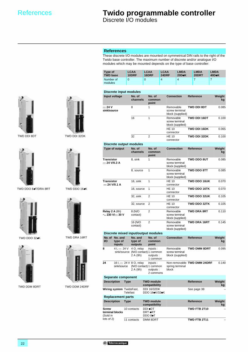
These discrete I/O modules are mounted on symmetrical DIN rails to the right of the Twido base controller. The maximum number of discrete and/or analogue I/O modules which may be mounted depends on the type of base controller:
References
Type of TWD base
LCAA 10DRF
LCAA 16DRF
LCAA 24DRF
LMDA 20DpK
LMDA 20DRT
LMDA 40DpK
Number of modules
0 0 4 4 7 7
TWD DDI 8DT TWD DDI 32DK
TWD DDO 16pKTWD DDO 8pT/DRA 8RT
TWD DDM 8DRT TWD DDM 24DRF
TWD DRA 16RTTWD DDO 32pK
Discrete input modulesInput voltage No. of
channelsNo. of common point
Connection Reference Weightkg
c 24 V sink/source
8 1 Removable screw terminal block (supplied)
TWD DDI 8DT 0.085
16 1 Removable screw terminal block (supplied)
TWD DDI 16DT 0.100
HE 10 connector
TWD DDI 16DK 0.065
32 2 HE 10 connector
TWD DDI 32DK 0.100
Discrete output modulesType of output No. of
channelsNo. of common point
Connection Reference Weightkg
Transistorc 24 V/0.3 A
8, sink 1 Removable screw terminal block (supplied)
TWD DDO 8UT 0.085
8, source 1 Removable screw terminal block (supplied)
TWD DDO 8TT 0.085
Transistor c 24 V/0.1 A
16, sink 1 HE 10 connector
TWD DDO 16UK 0.070
16, source 1 HE 10 connector
TWD DDO 16TK 0.070
32, sink 2 HE 10 connector
TWD DDO 32UK 0.105
32, source 2 HE 10 connector
TWD DDO 32TK 0.105
Relay 2 A (Ith)a 230 V/c 30 V
8 (N/O contact)
2 Removable screw terminal block (supplied)
TWD DRA 8RT 0.110
16 (N/O contact)
2 Removable screw terminal block (supplied)
TWD DRA 16RT 0.145
Discrete mixed input/output modulesNo. of I/O
No. and type of inputs
No. and type of outputs
No. of common point
Connection Reference Weightkg
8 4 I, c 24 V sink/source
4 O, relay(N/O contact)2 A (Ith)
inputs : 1 commonoutputs : 1 common
Removable screw terminal block (supplied)
TWD DMM 8DRT 0.095
24 16 I, c 24 Vsink/source
8 O, relay(N/O contact)2 A (Ith)
inputs : 1 commonoutputs : 2 commons
Non-removable spring terminal block
TWD DMM 24DRF 0.140
Separate componentDescription Type TWD module
compatibilityReference Weight
kgWiring system TwidoFast,
TelefastDDI 16/32DKDDO 16pK/32pK
See page 38 –
Replacement partsDescription Type TWD module
compatibilityReference Weight
kgScrewterminal blocks(Sold in lots of 2)
10 contacts DDI pDTDRT pRT DDO 8pT
TWD FTB 2T10 –
11 contacts DMM 8DRT TWD FTB 2T11 –
23
Dimensions,connections 0
Twido programmable controller 0
Discrete I/O module
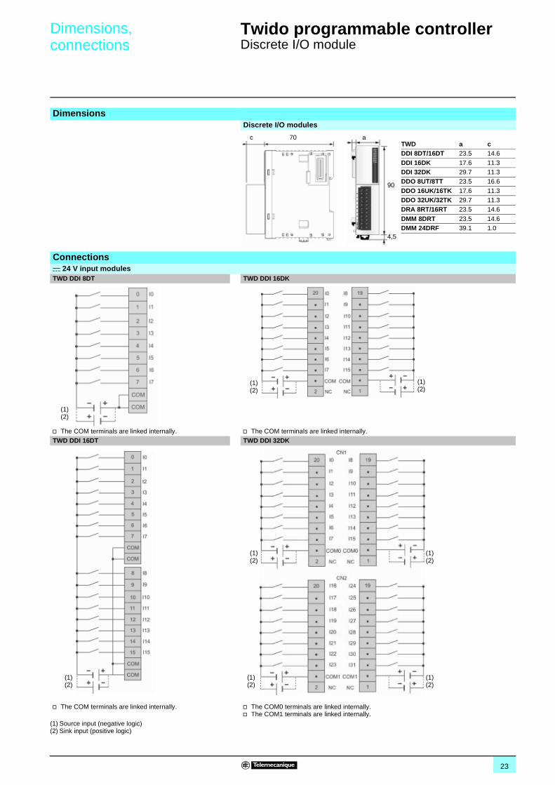
DimensionsDiscrete I/O modules
TWD a cDDI 8DT/16DT 23.5 14.6
DDI 16DK 17.6 11.3DDI 32DK 29.7 11.3DDO 8UT/8TT 23.5 16.6
DDO 16UK/16TK 17.6 11.3DDO 32UK/32TK 29.7 11.3DRA 8RT/16RT 23.5 14.6
DMM 8DRT 23.5 14.6DMM 24DRF 39.1 1.0
c 70 a
4,5
90
Connectionsc 24 V input modulesTWD DDI 8DT TWD DDI 16DK
v The COM terminals are linked internally. v The COM terminals are linked internally.
TWD DDI 16DT TWD DDI 32DK
v The COM terminals are linked internally. v The COM0 terminals are linked internally.v The COM1 terminals are linked internally.
(1) Source input (negative logic)(2) Sink input (positive logic)
(1)(2)
(1)(2)
(1)(2)
(1)(2)
(1)(2)
(1)(2)
(1)(2)
(1)(2)
24
Connections (continued) 0 Twido programmable controller 0
Discrete I/O modules
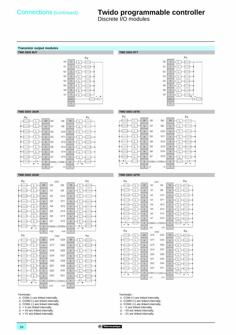
Transistor output modulesTWD DDO 8UT TWD DDO 8TT
TWD DDO 16UK TWD DDO 16TK
TWD DDO 32UK TWD DDO 32TK
Terminals :v COM (-) are linked internally.v COM0 (-) are linked internally.v COM1 (-) are linked internally.v + V are linked internally.v + V0 are linked internally.v + V1 are linked internally.
Terminals : v COM (+) are linked internally.v COM0 (+) are linked internally.v COM1 (+) are linked internally.v - V are linked internally.v - V0 are linked internally.v - V1 are linked internally.
Fu Fu
Fu Fu FuFu
FuFu
Fu Fu
FuFu
Fu Fu
25
Connections (continued) 0 Twido programmable controller 0
Discrete I/O modules
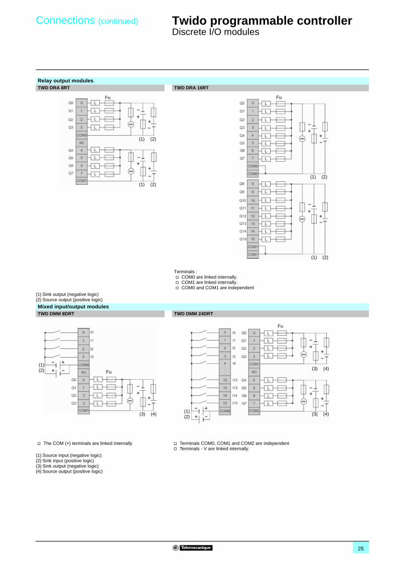
Relay output modulesTWD DRA 8RT TWD DRA 16RT
Terminals : v COM0 are linked internally.v COM1 are linked internally.v COM0 and COM1 are independent
(1) Sink output (negative logic)(2) Source output (positive logic)
Mixed input/output modulesTWD DMM 8DRT TWD DMM 24DRT
v The COM (+) terminals are linked internally v Terminals COM0, COM1 and COM2 are independentv Terminals - V are linked internally.
(1) Source input (negative logic)(2) Sink input (positive logic)(3) Sink output (negative logic)(4) Source output (positive logic)
(1) (2)
(1) (2)
Fu
(1) (2)
(1) (2)
Fu
(3) (4)
Fu
(1)(2) (3) (4)
(3) (4)
Fu
(1)(2)
26
Selection guide 0 Twido programmable controller 0
Analogue I/O modules
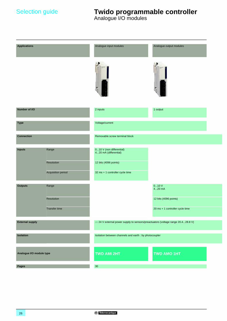
Applications Analogue input modules Analogue output modules
Number of I/O 2 inputs 1 output
Type Voltage/current
Connection Removable screw terminal block
Inputs Range 0...10 V (non differential)4...20 mA (differential)
Resolution 12 bits (4096 points)
Acquisition period 32 ms + 1 controller cycle time
Outputs Range 0...10 V4...20 mA
Resolution 12 bits (4096 points)
Transfer time 20 ms + 1 controller cycle time
External supply c 24 V external power supply to sensors/preactuators (voltage range 20.4...28.8 V)
Isolation Isolation between channels and earth : by photocoupler
Analogue I/O module type TWD AMI 2HT TWD AMO 1HT
Pages 30
27
00
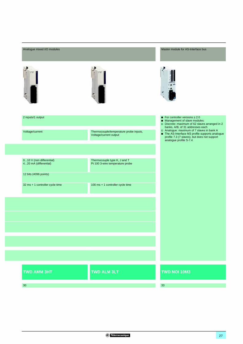
Analogue mixed I/O modules Master module for AS-Interface bus
2 inputs/1 output b For controller versions ≥ 2.0b Management of slave modules:v Discrete: maximum of 62 slaves arranged in 2
banks, A/B, of 31 addresses eachv Analogue: maximum of 7 slaves in bank Ab The AS-Interface M3 profile supports analogue
profile 7.3 (7 slaves), but does not support analogue profile S-7.4
Voltage/current Thermocouple/temperature probe inputs, Voltage/current output
0...10 V (non differential)4...20 mA (differential)
Thermocouple type K, J and TPt 100 3-wire temperature probe
12 bits (4096 points)
32 ms + 1 controller cycle time 100 ms + 1 controller cycle time
TWD AMM 3HT TWD ALM 3LT TWD NOI 10M3
30 33
28
Presentation,description 0
Twido programmable controller 0
Analogue I/O modules
Twido analogue I/O expansion modules enable the acquisition of various analogue values encountered in industrial applications, such as :
b High-level inputs (voltage 0…10 V or current 4…20 mA).b High-level outputs (voltage 0…10 V or current 4…20 mA).b Low level inputs from thermocouples type K, J and T.b Low level inputs from 3-wire Pt 100 temperature probes, range -100...500 °C.
Analogue output modules are used to control the preactuators in devices such as variable speed drives, valves and applications that require process control. The output current or the voltage is proportional to the numerical value defined by the user program. When the Twido controller stops, the outputs can be configured with fallback (reset to the lowest scale value or hold the last value received). This function, when set to 'hold', is useful when debugging the application or when a fault occurs, in order not to disturb the process being controlled.
The 4 following analogue I/O modules are available :
b One module with 2 high-level inputs.b One module with 1 high-level input.b One mixed module with 2 inputs and 1 high-level output.b One mixed module with 2 thermocouple or temperature probe inputs and 1 high-level output.
All Twido analogue extension modules offer 12-bit resolution (4096 points) with connection by removable screw terminal block. An external c 24 V power supply is required for each analogue module.
Like discrete I/O modules, analogue I/O modules are connected to the base controller by stacking them on a DIN rail, starting from the right-hand side panel of the base controller, according to the following rules :b For 24 I/O compact base controller TWD LCAA 24DRF : 4 modules max. (see characteristics page 6).b For 20 I/O modular base controllers TWD LMDA 20DpK : 4 modules max. (see characteristics page 13).b For 40 I/O modular base controllers TWD LMDA 20DRT/40DpK : 7 modules max. (see characteristics page 13).
All analogue I/O modules are electrically isolated with the use of a photocoupler between the internal electronic circuit and the input/output channels.
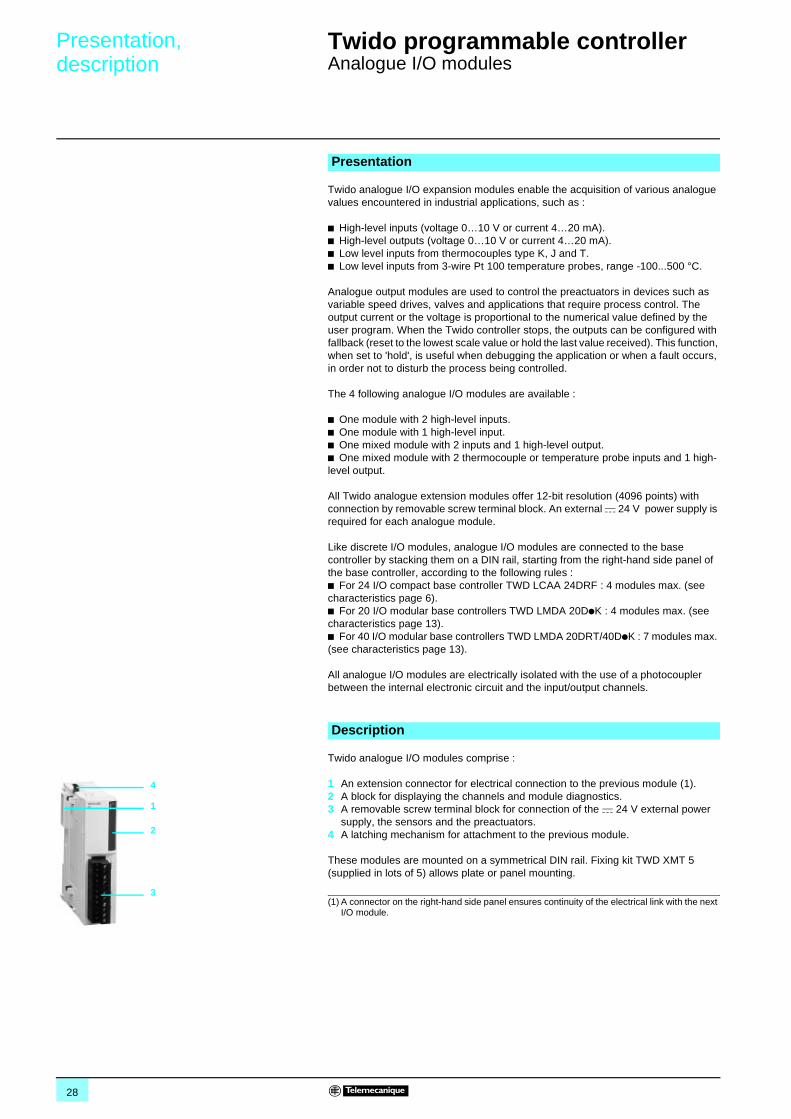
Twido analogue I/O modules comprise :
1 An extension connector for electrical connection to the previous module (1).2 A block for displaying the channels and module diagnostics.3 A removable screw terminal block for connection of the c 24 V external power
supply, the sensors and the preactuators.4 A latching mechanism for attachment to the previous module.
These modules are mounted on a symmetrical DIN rail. Fixing kit TWD XMT 5 (supplied in lots of 5) allows plate or panel mounting.
(1) A connector on the right-hand side panel ensures continuity of the electrical link with the next I/O module.
Presentation
Description
1
2
3
4
29
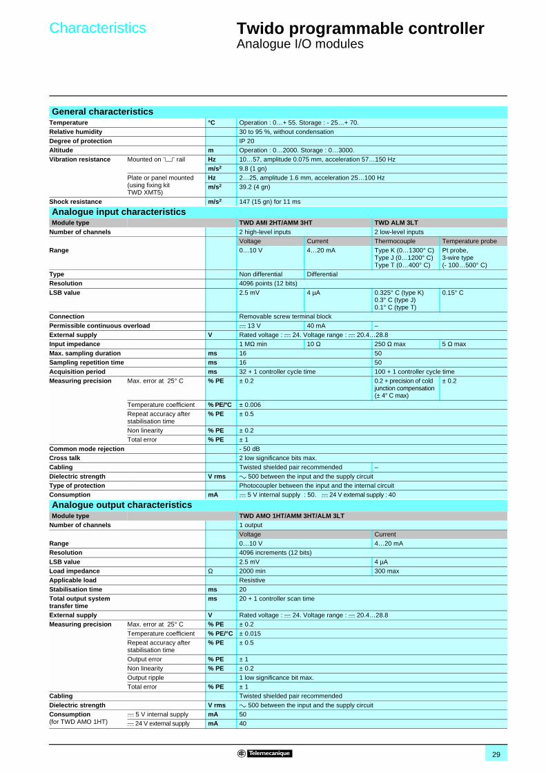
Characteristics 0 Twido programmable controller 0
Analogue I/O modules
General characteristicsTemperature °C Operation : 0…+ 55. Storage : - 25…+ 70.Relative humidity 30 to 95 %, without condensation
Degree of protection IP 20Altitude m Operation : 0…2000. Storage : 0…3000.Vibration resistance Mounted on 5 rail Hz 10…57, amplitude 0.075 mm, acceleration 57…150 Hz
m/s2 9.8 (1 gn)Plate or panel mounted (using fixing kit TWD XMT5)
Hz 2…25, amplitude 1.6 mm, acceleration 25…100 Hzm/s2 39.2 (4 gn)
Shock resistance m/s2 147 (15 gn) for 11 ms
Analogue input characteristicsModule type TWD AMI 2HT/AMM 3HT TWD ALM 3LT
Number of channels 2 high-level inputs 2 low-level inputsVoltage Current Thermocouple Temperature probe
Range 0…10 V 4…20 mA Type K (0…1300° C)Type J (0…1200° C)Type T (0…400° C)
Pt probe,3-wire type(- 100…500° C)
Type Non differential DifferentialResolution 4096 points (12 bits)
LSB value 2.5 mV 4 µA 0.325° C (type K)0.3° C (type J)0.1° C (type T)
0.15° C
Connection Removable screw terminal block
Permissible continuous overload c 13 V 40 mA –External supply V Rated voltage : c 24. Voltage range : c 20.4…28.8Input impedance 1 MΩ min 10 Ω 250 Ω max 5 Ω max
Max. sampling duration ms 16 50Sampling repetition time ms 16 50
Acquisition period ms 32 + 1 controller cycle time 100 + 1 controller cycle timeMeasuring precision Max. error at 25° C % PE ± 0.2 0.2 + precision of cold
junction compensation(± 4° C max)
± 0.2
Temperature coefficient % PE/°C ± 0.006Repeat accuracy after stabilisation time
% PE ± 0.5
Non linearity % PE ± 0.2Total error % PE ± 1
Common mode rejection - 50 dBCross talk 2 low significance bits max.Cabling Twisted shielded pair recommended –
Dielectric strength V rms a 500 between the input and the supply circuitType of protection Photocoupler between the input and the internal circuitConsumption mA c 5 V internal supply : 50. c 24 V external supply : 40
Analogue output characteristicsModule type TWD AMO 1HT/AMM 3HT/ALM 3LT
Number of channels 1 output
Voltage CurrentRange 0…10 V 4…20 mAResolution 4096 increments (12 bits)
LSB value 2.5 mV 4 µALoad impedance Ω 2000 min 300 maxApplicable load Resistive
Stabilisation time ms 20Total output system transfer time
ms 20 + 1 controller scan time
External supply V Rated voltage : c 24. Voltage range : c 20.4…28.8Measuring precision Max. error at 25° C % PE ± 0.2
Temperature coefficient % PE/°C ± 0.015Repeat accuracy after stabilisation time
% PE ± 0.5
Output error % PE ± 1Non linearity % PE ± 0.2
Output ripple 1 low significance bit max.Total error % PE ± 1
Cabling Twisted shielded pair recommended
Dielectric strength V rms a 500 between the input and the supply circuitConsumption(for TWD AMO 1HT)
c 5 V internal supply mA 50c 24 V external supply mA 40
30
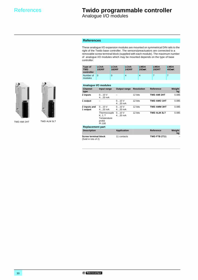
References 0 Twido programmable controller 0
Analogue I/O modules
These analogue I/O expansion modules are mounted on symmetrical DIN rails to the right of the Twido base controller. The sensors/preactuators are connected to a removable screw terminal block (supplied with each module). The maximum number of analogue I/O modules which may be mounted depends on the type of base controller:
References
Type of TWD controller
LCAA 10DRF
LCAA 16DRF
LCAA 24DRF
LMDA 20DpK
LMDA 20DRT
LMDA 40DpK
Number of modules
0 0 4 4 7 7
TWD AMI 2HT TWD ALM 3LT
Analogue I/O modulesChanneltype
Input range Output range Resolution Reference Weightkg
2 inputs 0…10 V4…20 mA
– 12 bits TWD AMI 2HT 0.085
1 output – 0…10 V4…20 mA
12 bits TWD AMO 1HT 0.085
2 inputs and1 output
0…10 V4…20 mA
0…10 V4…20 mA
12 bits TWD AMM 3HT 0.085
Thermocouple K, J, TTemperature probePt 100
0…10 V4…20 mA
12 bits TWD ALM 3LT 0.085
Replacement partDescription Application Reference Weight
kgScrew terminal block(Sold in lots of 2)
11 contacts TWD FTB 2T11 –
31
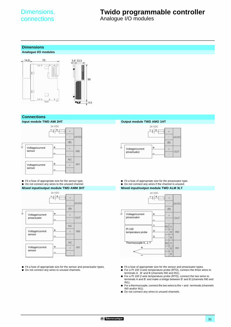
Dimensions,connections 0
Twido programmable controller 0
Analogue I/O modules
DimensionsAnalogue I/O modules
ConnectionsInput module TWD AMI 2HT Output module TWD AMO 1HT
b Fit a fuse of appropriate size for the sensor type.b Do not connect any wires to the unused channel.
b Fit a fuse of appropriate size for the preactuator type.b Do not connect any wires if the channel is unused.
Mixed input/output module TWD AMM 3HT Mixed input/output module TWD ALM 3LT
b Fit a fuse of appropriate size for the sensor and preactuator types.b Do not connect any wires to unused channels.
b Fit a fuse of appropriate size for the sensor and preactuator types.b For a Pt 100 3-wire temperature probe (RTD), connect the three wires to
terminals A , B’ and B (channels IN0 and IN1).b For a Pt 100 2-wire temperature probe (RTD), connect the two wires to
terminals A and B’ and make a bridge between B' and B (channels IN0 and IN1).
b For a thermocouple, connect the two wires to the + and - terminals (channels IN0 and/or IN1).
b Do not connect any wires to unused channels.
3,8 23,5
4,5
90
Voltage/current sensor
Voltage/current sensor
Voltage/current preactuator
Voltage/current preactuator
Voltage/current sensor
Voltage/current sensor
Voltage/current preactuator
Pt 100temperature probe
Thermocouple K, J, T
32
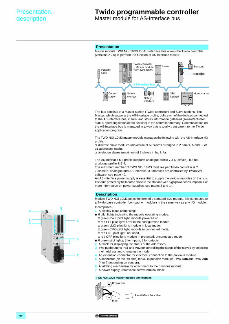
Presentation,description 0
Twido programmable controller 0
Master module for AS-Interface bus
Master module TWD NOI 10M3 for AS-Interface bus allows the Twido controller (versions u 2.0) to perform the function of AS-Interface master.
The bus consists of a Master station (Twido controller) and Slave stations. The Master, which supports the AS-Interface profile, polls each of the devices connected to the AS-Interface bus, in turn, and stores information gathered (sensor/actuator status, operating status of the devices) in the controller memory. Communication on the AS-Interface bus is managed in a way that is totally transparent to the Twido application program.
The TWD NOI 10M3 master module manages the following with the AS-Interface M3 profile:v discrete slave modules (maximum of 62 slaves arranged in 2 banks, A and B, of 31 addresses each),v analogue slaves (maximum of 7 slaves in bank A).
The AS-Interface M3 profile supports analogue profile 7.3 (7 slaves), but not analogue profile S-7.4.The maximum number of TWD NOI 10M3 modules per Twido controller is 2. 7 discrete, analogue and AS-Interface I/O modules are controlled by TwidoSfot software, see page 40.An AS-Interface power supply is essential to supply the various modules on the bus. It should preferably be located close to the stations with high power consumption. For more information on power supplies, see pages 8 and 14.
Module TWD NOI 10M3 takes the form of a standard-size module. It is connected to a Twido base controller (compact or modular) in the same way as any I/O module.
Presentation
SensorsPower
Control station
Twido controller + Master module TWD NOI 10M3
AS-Interface bus
Indicator bank
Safety monitor
Motor starter
Safety interface
XBL keypad
Description
It comprises:1 A display block comprising:b 6 pilot lights indicating the module operating modes:
v green PWR pilot light: module powered up,v red FLT pilot light: error in the configuration loaded,v green LMO pilot light: module in local mode,v green CMO pilot light: module in connected mode,v red CNF pilot light: not used,v red OFF pilot light: module in protected, unconnected mode.
b 6 green pilot lights, 3 for inputs, 3 for outputs.2 A block for displaying the status of the addresses.3 Two pushbuttons PB1 and PB2 for controlling the status of the slaves by selecting
their address and changing the mode.4 An extension connector for electrical connection to the previous module.5 A connector (on the RH side) for I/O expansion modules TWD Dpp and TWD App
(4 or 7 depending on version).6 A latching mechanism for attachment to the previous module.7 A power supply removable screw terminal block.
TWD NOI 10M3 master module connections
14
2
65
3
7
Brown wire
Blue
As-Interface flat cable
33
Diagnostics, characteristics,references 0
Twido programmable controller 0
Master module for AS-Interface bus
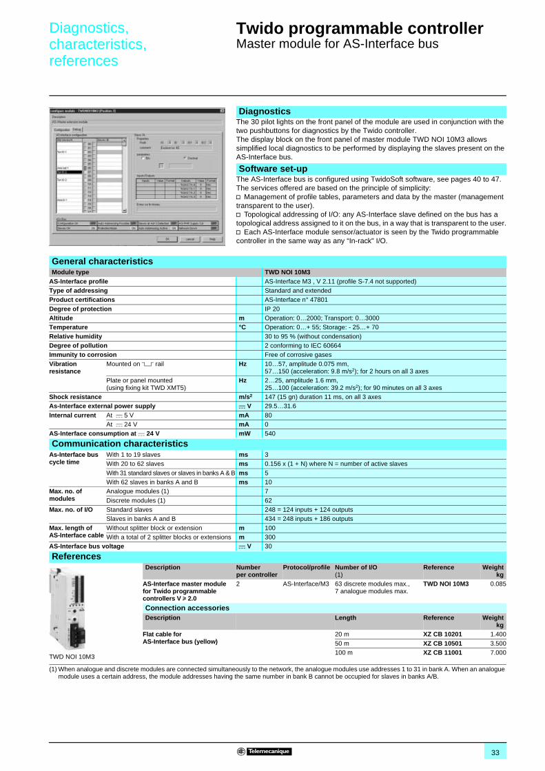
The 30 pilot lights on the front panel of the module are used in conjunction with the two pushbuttons for diagnostics by the Twido controller.The display block on the front panel of master module TWD NOI 10M3 allows simplified local diagnostics to be performed by displaying the slaves present on the AS-Interface bus.
The AS-Interface bus is configured using TwidoSoft software, see pages 40 to 47. The services offered are based on the principle of simplicity: v Management of profile tables, parameters and data by the master (management transparent to the user).v Topological addressing of I/O: any AS-Interface slave defined on the bus has a topological address assigned to it on the bus, in a way that is transparent to the user.v Each AS-Interface module sensor/actuator is seen by the Twido programmable controller in the same way as any “In-rack" I/O.
Diagnostics
Software set-up
General characteristicsModule type TWD NOI 10M3
AS-Interface profile AS-Interface M3 , V 2.11 (profile S-7.4 not supported)Type of addressing Standard and extendedProduct certifications AS-Interface n° 47801
Degree of protection IP 20Altitude m Operation: 0…2000; Transport: 0…3000Temperature °C Operation: 0…+ 55; Storage: - 25…+ 70
Relative humidity 30 to 95 % (without condensation)Degree of pollution 2 conforming to IEC 60664Immunity to corrosion Free of corrosive gases
Vibration resistance
Mounted on 5 rail Hz 10…57, amplitude 0.075 mm, 57…150 (acceleration: 9.8 m/s2); for 2 hours on all 3 axes
Plate or panel mounted (using fixing kit TWD XMT5)
Hz 2…25, amplitude 1.6 mm, 25…100 (acceleration: 39.2 m/s2); for 90 minutes on all 3 axes
Shock resistance m/s2 147 (15 gn) duration 11 ms, on all 3 axesAs-Interface external power supply c V 29.5…31.6
Internal current At c 5 V mA 80At c 24 V mA 0
AS-Interface consumption at c 24 V mW 540
Communication characteristicsAs-Interface bus cycle time
With 1 to 19 slaves ms 3With 20 to 62 slaves ms 0.156 x (1 + N) where N = number of active slaves
With 31 standard slaves or slaves in banks A & B ms 5With 62 slaves in banks A and B ms 10
Max. no. of modules
Analogue modules (1) 7
Discrete modules (1) 62Max. no. of I/O Standard slaves 248 = 124 inputs + 124 outputs
Slaves in banks A and B 434 = 248 inputs + 186 outputs
Max. length of AS-Interface cable
Without splitter block or extension m 100With a total of 2 splitter blocks or extensions m 300
AS-Interface bus voltage c V 30
ReferencesDescription Number
per controllerProtocol/profile Number of I/O
(1)Reference Weight
kgAS-Interface master module for Twido programmable controllers V u 2.0
2 AS-Interface/M3 63 discrete modules max.,7 analogue modules max.
TWD NOI 10M3 0.085
Connection accessoriesDescription Length Reference Weight
kgFlat cable for AS-Interface bus (yellow)
20 m XZ CB 10201 1.400
50 m XZ CB 10501 3.500100 m XZ CB 11001 7.000
(1) When analogue and discrete modules are connected simultaneously to the network, the analogue modules use addresses 1 to 31 in bank A. When an analogue module uses a certain address, the module addresses having the same number in bank B cannot be occupied for slaves in banks A/B.
TWD NOI 10M3
34
Presentation,description 0
Twido programmable controller 0
Communication
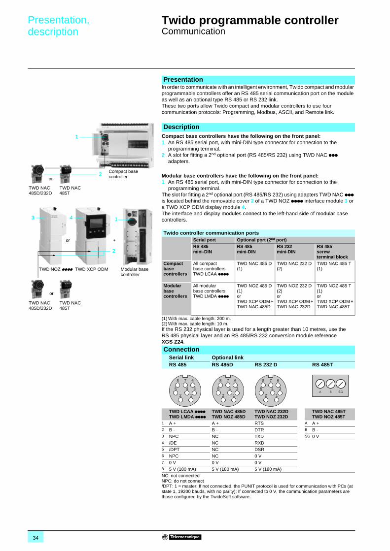
In order to communicate with an intelligent environment, Twido compact and modular programmable controllers offer an RS 485 serial communication port on the module as well as an optional type RS 485 or RS 232 link. These two ports allow Twido compact and modular controllers to use four communication protocols: Programming, Modbus, ASCII, and Remote link.
Compact base controllers have the following on the front panel: 1 An RS 485 serial port, with mini-DIN type connector for connection to the
programming terminal.2 A slot for fitting a 2nd optional port (RS 485/RS 232) using TWD NAC ppp
adapters.
Modular base controllers have the following on the front panel: 1 An RS 485 serial port, with mini-DIN type connector for connection to the
programming terminal.The slot for fitting a 2nd optional port (RS 485/RS 232) using adapters TWD NAC ppp is located behind the removable cover 2 of a TWD NOZ pppp interface module 3 or a TWD XCP ODM display module 4.The interface and display modules connect to the left-hand side of modular base controllers.
Presentation
Description1
2
TWD NAC 485D/232D
TWD NAC 485T
Compact base controlleror
Modular base controller
TWD NAC 485D/232D
TWD NAC 485T
TWD NOZ pppp
1
or
3 4
2
or +
TWD XCP ODM
Twido controller communication portsSerial port Optional port (2nd port)RS 485 mini-DIN
RS 485mini-DIN
RS 232mini-DIN
RS 485screw terminal block
Compact base controllers
All compact base controllers TWD LCAA pppp
TWD NAC 485 D (1)
TWD NAC 232 D (2)
TWD NAC 485 T (1)
Modular base controllers
All modular base controllers TWD LMDA pppp
TWD NOZ 485 D (1) orTWD XCP ODM + TWD NAC 485D
TWD NOZ 232 D (2) orTWD XCP ODM + TWD NAC 232D
TWD NOZ 485 T (1) orTWD XCP ODM + TWD NAC 485T
(1) With max. cable length: 200 m.(2) With max. cable length: 10 m.If the RS 232 physical layer is used for a length greater than 10 metres, use the RS 485 physical layer and an RS 485/RS 232 conversion module reference XGS Z24.
ConnectionSerial link Optional linkRS 485 RS 485D RS 232 D RS 485T
TWD LCAA ppppTWD LMDA pppp
TWD NAC 485DTWD NOZ 485D
TWD NAC 232DTWD NOZ 232D
TWD NAC 485TTWD NOZ 485T
1 A + A + RTS A A +2 B - B - DTR B B -3 NPC NC TXD SG 0 V4 /DE NC RXD5 /DPT NC DSR6 NPC NC 0 V7 0 V 0 V 0 V8 5 V (180 mA) 5 V (180 mA) 5 V (180 mA)NC: not connectedNPC: do not connect/DPT: 1 = master; If not connected, the PUNIT protocol is used for communication with PCs (at state 1, 19200 bauds, with no parity); If connected to 0 V, the communication parameters are those configured by the TwidoSoft software.
12
45 3
8 7 6
12
45 3
8 7 6
12
45 3
8 7 6
A B SG
35
References,dimensions 0
Twido programmable controller 0
Communication
ReferencesSerial link modules and adaptersDescription Compatibility Physical layer Connection Reference Weight
kgSerial interface adapters Compact base controllers
TWD LCAA 16/24DRFBuilt-in display module TWD XCP ODM
RS 232C Mini-DIN connector
TWD NAC 232D 0.010
RS 485 Mini-DIN connector
TWD NAC 485D 0.010
Screw terminals TWD NAC 485T 0.010
Serial interface modules Modular base controllers TWD LMDA 20/40Dpp
RS 232C Mini-DIN connector
TWD NOZ 232D 0.085
RS 485 Mini-DIN connector
TWD NOZ 485D 0.085
Screw terminals TWD NOZ 485T 0.085
Digital display and built-in display moduleDescription Compatibility Characteristics Reference Weight
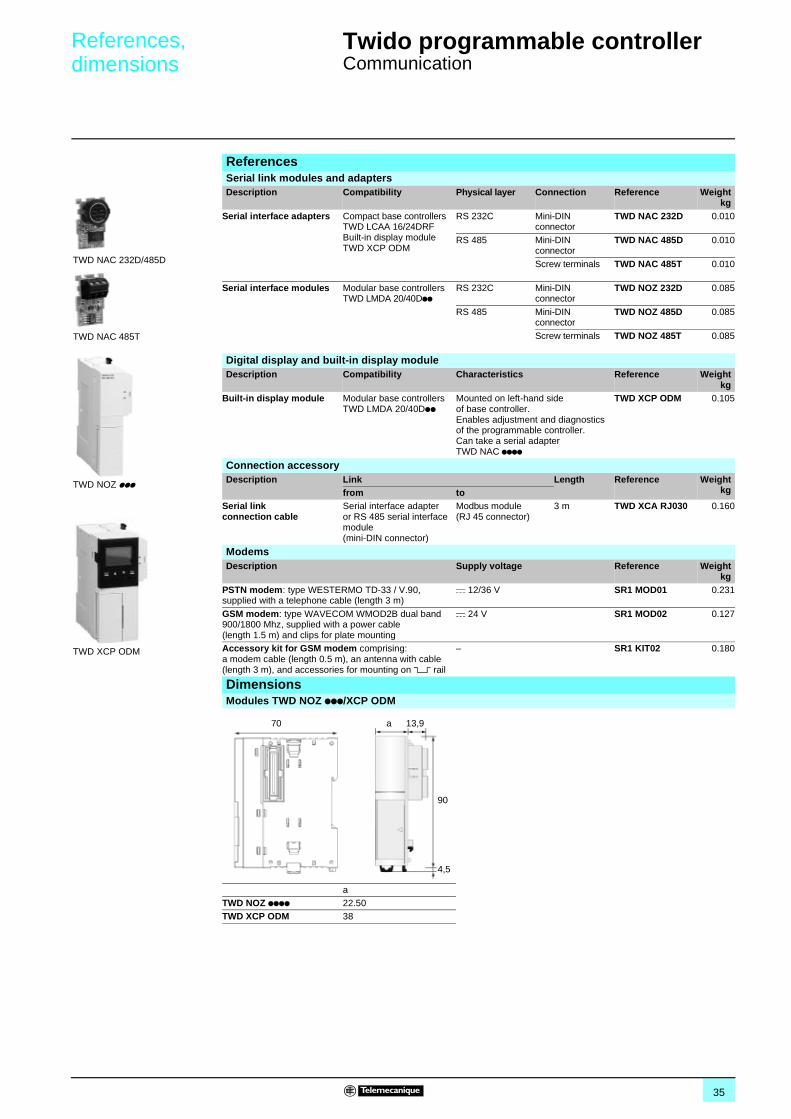
kgBuilt-in display module Modular base controllers
TWD LMDA 20/40DppMounted on left-hand side of base controller.Enables adjustment and diagnostics of the programmable controller.Can take a serial adapter TWD NAC pppp
TWD XCP ODM 0.105
Connection accessoryDescription Link Length Reference Weight
kgfrom toSerial linkconnection cable
Serial interface adapter or RS 485 serial interface module (mini-DIN connector)
Modbus module (RJ 45 connector)
3 m TWD XCA RJ030 0.160
ModemsDescription Supply voltage Reference Weight
kgPSTN modem: type WESTERMO TD-33 / V.90, supplied with a telephone cable (length 3 m)
c 12/36 V SR1 MOD01 0.231
GSM modem: type WAVECOM WMOD2B dual band 900/1800 Mhz, supplied with a power cable (length 1.5 m) and clips for plate mounting
c 24 V SR1 MOD02 0.127
Accessory kit for GSM modem comprising: a modem cable (length 0.5 m), an antenna with cable (length 3 m), and accessories for mounting on 5 rail
– SR1 KIT02 0.180
DimensionsModules TWD NOZ ppp/XCP ODM
aTWD NOZ pppp 22.50TWD XCP ODM 38
TWD NOZ ppp
TWD NAC 232D/485D
TWD XCP ODM
TWD NAC 485T
70 a
4,5
90
13,9
36
Presentation,characteristics 0
Twido programmable controller 0
Communication protocols
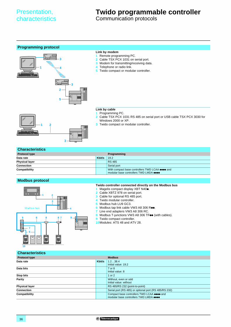
Programming protocolLink by modem1 Remote programming PC.2 Cable TSX PCX 1031 on serial port.3 Modem for transmitting/receiving data.4 Telephone or radio link.5 Twido compact or modular controller.
Link by cable1 Programming PC.2 Cable TSX PCX 1031 RS 485 on serial port or USB cable TSX PCX 3030 for
Windows 2000 or XP.3 Twido compact or modular controller.
CharacteristicsProtocol type Programming
Data rate Kbit/s 19.2Physical layer RS 485Connection Serial port
Compatibility With compact base controllers TWD LCAA pppp and modular base controllers TWD LMDA pppp
Modbus protocolTwido controller connected directly on the Modbus bus1 Magelis compact display XBT N40p. 2 Cable XBTZ 978 on serial port.3 Cable for optional RS 485 port.4 Twido modular controller.5 Modbus hub LU9 GC3.6 Modbus tap link cable VW3 A8 306 Rpp.7 Line end adapters VW3 A8 306 RC.8 Modbus T-junctions VW3 A8 306 TFpp (with cables).9 Twido compact controller.10Modules: ATS 48 and ATV 28.
CharacteristicsProtocol type Modbus
Data rate Kbit/s 1.2…38.4Initial value: 19.2
Data bits 7 or 8Initial value: 8
Stop bits 1 or 2Parity Without, even or odd
Initial value: withoutPhysical layer RS 485/RS 232 (point-to-point)Connection Serial port (RS 485) or optional port (RS 485/RS 232)
Compatibility Compact base controllers TWD LCAA pppp and modular base controllers TWD LMDA pppp
1
3
4
3
5
2
1 2
3
7
6
65 8 8 7 9
3
1
10
2
4Modbus bus
37
Presentation,characteristics 0
Twido programmable controller 0
Communication protocols
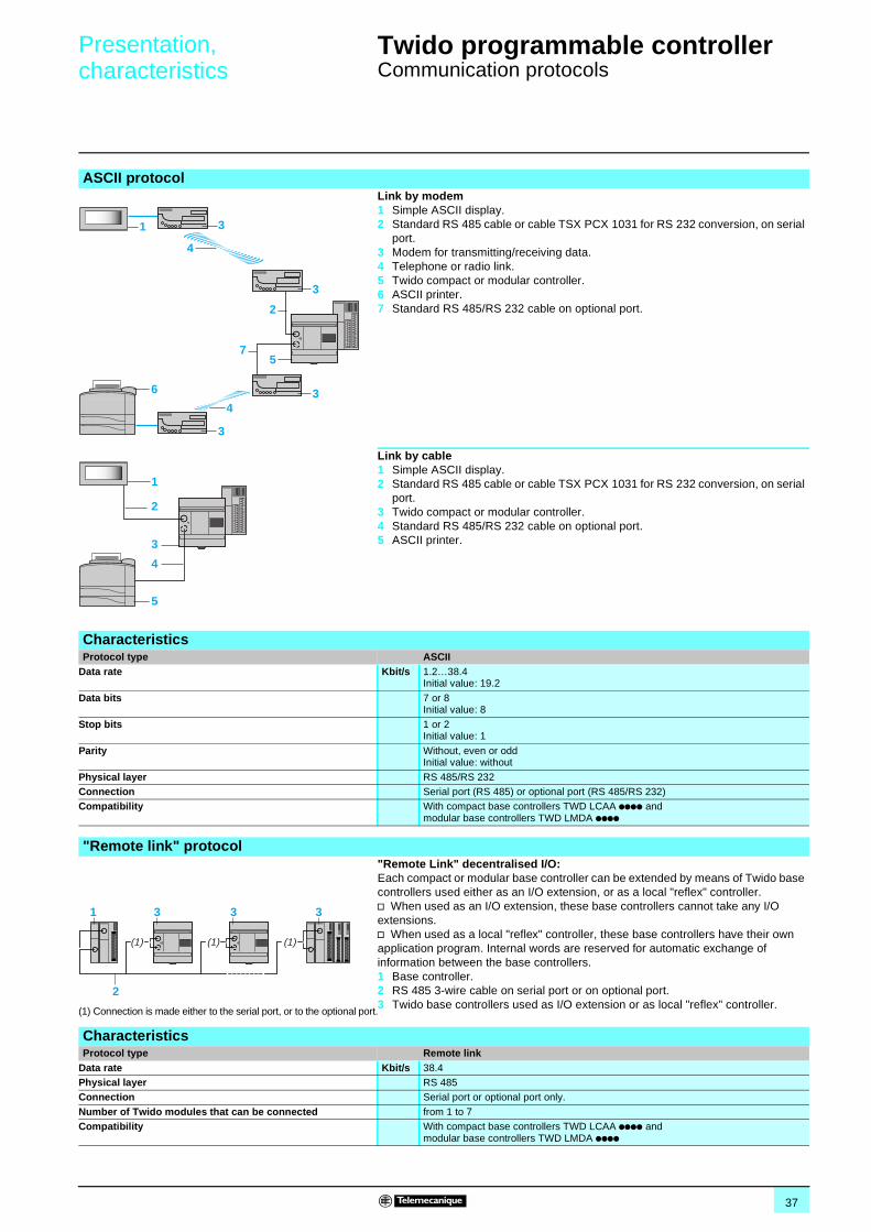
ASCII protocolLink by modem1 Simple ASCII display.2 Standard RS 485 cable or cable TSX PCX 1031 for RS 232 conversion, on serial
port.3 Modem for transmitting/receiving data.4 Telephone or radio link.5 Twido compact or modular controller.6 ASCII printer.7 Standard RS 485/RS 232 cable on optional port.
Link by cable1 Simple ASCII display.2 Standard RS 485 cable or cable TSX PCX 1031 for RS 232 conversion, on serial
port.3 Twido compact or modular controller.4 Standard RS 485/RS 232 cable on optional port.5 ASCII printer.
CharacteristicsProtocol type ASCII
Data rate Kbit/s 1.2…38.4Initial value: 19.2
Data bits 7 or 8Initial value: 8
Stop bits 1 or 2Initial value: 1
Parity Without, even or oddInitial value: without
Physical layer RS 485/RS 232Connection Serial port (RS 485) or optional port (RS 485/RS 232)Compatibility With compact base controllers TWD LCAA pppp and
modular base controllers TWD LMDA pppp
1
6
3
3
4
4
3
3
5
2
7
1
5
3
2
4
"Remote link" protocol
(1) Connection is made either to the serial port, or to the optional port.
"Remote Link" decentralised I/O: Each compact or modular base controller can be extended by means of Twido base controllers used either as an I/O extension, or as a local "reflex" controller. v When used as an I/O extension, these base controllers cannot take any I/O extensions.v When used as a local "reflex" controller, these base controllers have their own application program. Internal words are reserved for automatic exchange of information between the base controllers.1 Base controller. 2 RS 485 3-wire cable on serial port or on optional port.3 Twido base controllers used as I/O extension or as local "reflex" controller.
CharacteristicsProtocol type Remote link
Data rate Kbit/s 38.4Physical layer RS 485 Connection Serial port or optional port only.
Number of Twido modules that can be connected from 1 to 7Compatibility With compact base controllers TWD LCAA pppp and
modular base controllers TWD LMDA pppp
1 3 3
2
(1)(1)
3
(1)
38
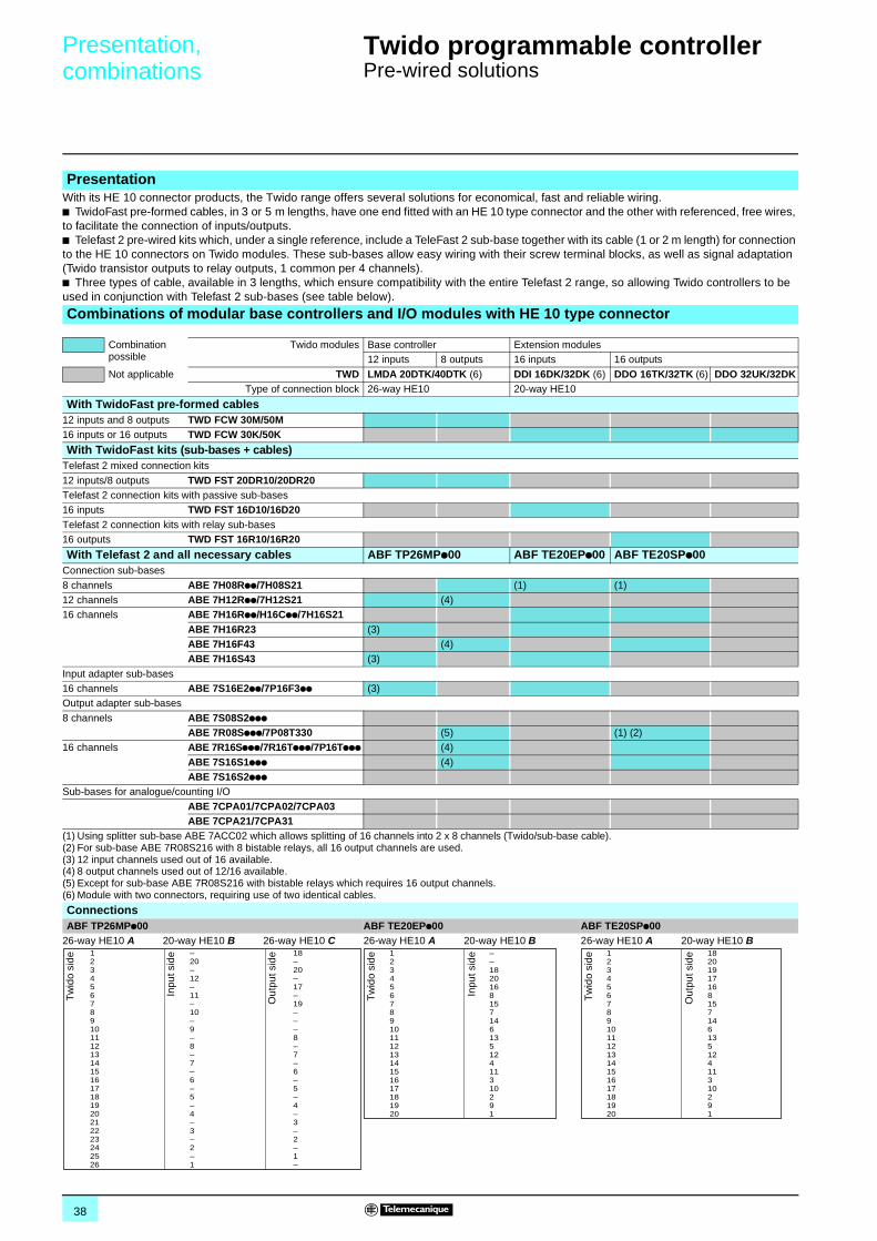
Presentation,combinations 0
Twido programmable controller 0
Pre-wired solutions
PresentationWith its HE 10 connector products, the Twido range offers several solutions for economical, fast and reliable wiring.b TwidoFast pre-formed cables, in 3 or 5 m lengths, have one end fitted with an HE 10 type connector and the other with referenced, free wires, to facilitate the connection of inputs/outputs.b Telefast 2 pre-wired kits which, under a single reference, include a TeleFast 2 sub-base together with its cable (1 or 2 m length) for connection to the HE 10 connectors on Twido modules. These sub-bases allow easy wiring with their screw terminal blocks, as well as signal adaptation (Twido transistor outputs to relay outputs, 1 common per 4 channels).b Three types of cable, available in 3 lengths, which ensure compatibility with the entire Telefast 2 range, so allowing Twido controllers to be used in conjunction with Telefast 2 sub-bases (see table below).
Combinations of modular base controllers and I/O modules with HE 10 type connector
Combination possible
Twido modules Base controller Extension modules12 inputs 8 outputs 16 inputs 16 outputs
Not applicable TWD LMDA 20DTK/40DTK (6) DDI 16DK/32DK (6) DDO 16TK/32TK (6) DDO 32UK/32DKType of connection block 26-way HE10 20-way HE10
With TwidoFast pre-formed cables12 inputs and 8 outputs TWD FCW 30M/50M16 inputs or 16 outputs TWD FCW 30K/50K
With TwidoFast kits (sub-bases + cables)Telefast 2 mixed connection kits
12 inputs/8 outputs TWD FST 20DR10/20DR20 Telefast 2 connection kits with passive sub-bases16 inputs TWD FST 16D10/16D20Telefast 2 connection kits with relay sub-bases16 outputs TWD FST 16R10/16R20
With Telefast 2 and all necessary cables ABF TP26MPp00 ABF TE20EPp00 ABF TE20SPp00Connection sub-bases
8 channels ABE 7H08Rpp/7H08S21 (1) (1)12 channels ABE 7H12Rpp/7H12S21 (4)16 channels ABE 7H16Rpp/H16Cpp/7H16S21
ABE 7H16R23 (3)ABE 7H16F43 (4)ABE 7H16S43 (3)
Input adapter sub-bases16 channels ABE 7S16E2pp/7P16F3pp (3)Output adapter sub-bases
8 channels ABE 7S08S2pppABE 7R08Sppp/7P08T330 (5) (1) (2)
16 channels ABE 7R16Sppp/7R16Tppp/7P16Tppp (4)
ABE 7S16S1ppp (4)ABE 7S16S2ppp
Sub-bases for analogue/counting I/O
ABE 7CPA01/7CPA02/7CPA03ABE 7CPA21/7CPA31
(1) Using splitter sub-base ABE 7ACC02 which allows splitting of 16 channels into 2 x 8 channels (Twido/sub-base cable).(2) For sub-base ABE 7R08S216 with 8 bistable relays, all 16 output channels are used.(3) 12 input channels used out of 16 available.(4) 8 output channels used out of 12/16 available.(5) Except for sub-base ABE 7R08S216 with bistable relays which requires 16 output channels.(6) Module with two connectors, requiring use of two identical cables.
ConnectionsABF TP26MPp00 ABF TE20EPp00 ABF TE20SPp00
26-way HE10 A 20-way HE10 B 26-way HE10 C 26-way HE10 A 20-way HE10 B 26-way HE10 A 20-way HE10 B1234567891011121314151617181920212223242526
18–20–17–19–––8–7–6–5–4–3–2–1–
–20–12–11–10–9–8–7–6–5–4–3–2–1
Tw
ido
side
Inpu
t sid
e
Out
put s
ide 1
234567891011121314151617181920
––182016815714613512 411310291
Tw
ido
side
Inpu
t sid
e 1234567891011121314151617181920
1820191716815714613512411310291
Tw
ido
side
Out
put s
ide
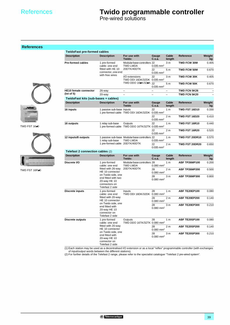
39
References 0 Twido programmable controller 0
Pre-wired solutions
ReferencesTwidoFast pre-formed cablesDescription Description For use with
Twido:GaugeC.s.a.
Cable length
Reference Weightkg
Pre-formed cables 1 pre-formed cable: one end fitted with HE 10 connector, one end with free wires
Modular base controllers TWD LMDA20DTK/40DTK
220.035 mm2
3 m TWD FCW 30M 0.405
220.035 mm2
5 m TWD FCW 50M 0.670
I/O extensions TWD DDI 16DK/32DK TWD DDO 16pK/32pK
220.035 mm2
3 m TWD FCW 30K 0.405
220.035 mm2
5 m TWD FCW 50K 0.670
HE10 female connector(lot of 5)
26-way – – – TWD FCN 5K26 –20-way – – – TWD FCN 5K20 –
TwidoFast kits (sub-bases + cables)Description Description For use with
TwidoGaugeC.s.a.
Cable length
Reference Weightkg
16 inputs 1 passive sub-base1 pre-formed cable
InputsTWD DDI 16DK/32DK
220.035 mm2
1 m TWD FST 16D10 0.330
220.035 mm2
2 m TWD FST 16D20 0.410
16 outputs 1 relay sub-base1 pre-formed cable
Outputs TWD DDO 16TK/32TK
220.035 mm2
1 m TWD FST 16R10 0.440
220.035 mm2
2 m TWD FST 16R20 0.520
12 inputs/8 outputs 1 passive sub-base1 relay sub-base1 pre-formed cable
Modular base controllers TWD LMDA20DTK/40DTK
220.035 mm2
1 m TWD FST 20DR10 0.570
220.035 mm2
2 m TWD FST 20DR20 0.650
Telefast 2 connection cables (2)
Description Description For use with Twido:
GaugeC.s.a.
Cable length
Reference Weightkg
Discrete I/O 1 pre-formed cable: one end fitted with 26-way HE 10 connector on Twido side, one end fitted with two 20-way HE 10 connectors on Telefast 2 side
Modular base controllers TWD LMDA20DTK/40DTK
280.080 mm2
1 m ABF TP26MP100 0.200
280.080 mm2
2 m ABF TP26MP200 0.500
280.080 mm2
3 m ABF TP26MP300 0.800
Discrete inputs 1 pre-formed cable: one end fitted with 20-way HE 10 connector on Twido side, one end fitted with 20-way HE 10 connector on Telefast 2 side
InputsTWD DDI 16DK/32DK
280.080 mm2
1 m ABF TE20EP100 0.080
280.080 mm2
2 m ABF TE20EP200 0.140
280.080 mm2
3 m ABF TE20EP300 0.210
Discrete outputs 1 pre-formed cable: one end fitted with 20-way HE 10 connector on Twido side, one end fitted with 20-way HE 10 connector on Telefast 2 side
Outputs TWD DDO 16TK/32TK
280.080 mm2
1 m ABF TE20SP100 0.080
280.080 mm2
2 m ABF TE20SP200 0.140
280.080 mm2
3 m ABF TE20SP300 0.210
(1) Each station may be used as a decentralised I/O extension or as a local "reflex" programmable controller (with exchanges of input/output words between the different stations).
(2) For further details of the Telefast 2 range, please refer to the specialist catalogue “Telefast 2 pre-wired system”.
TWD FST 16p0
TWD FST 16Rp0
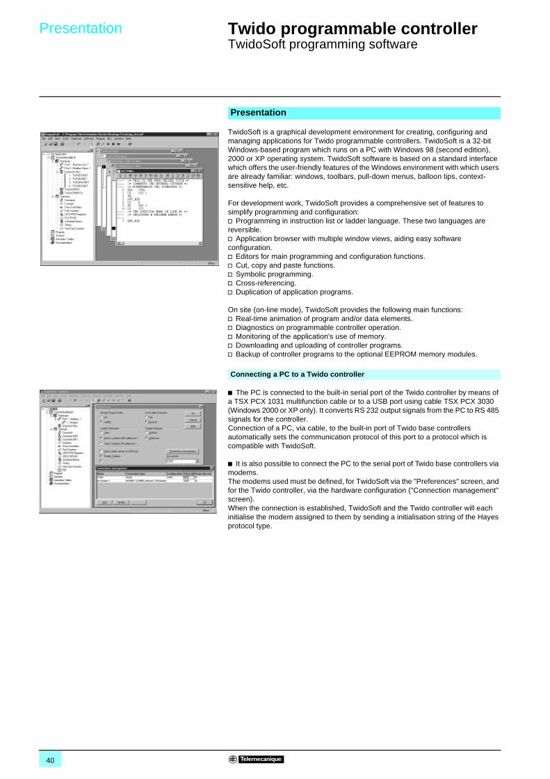
40
Presentation 0 Twido programmable controller 0
TwidoSoft programming software
TwidoSoft is a graphical development environment for creating, configuring and managing applications for Twido programmable controllers. TwidoSoft is a 32-bit Windows-based program which runs on a PC with Windows 98 (second edition), 2000 or XP operating system. TwidoSoft software is based on a standard interface which offers the user-friendly features of the Windows environment with which users are already familiar: windows, toolbars, pull-down menus, balloon tips, context-sensitive help, etc.
For development work, TwidoSoft provides a comprehensive set of features to simplify programming and configuration:v Programming in instruction list or ladder language. These two languages are reversible.v Application browser with multiple window views, aiding easy software configuration.v Editors for main programming and configuration functions.v Cut, copy and paste functions.v Symbolic programming.v Cross-referencing.v Duplication of application programs.
On site (on-line mode), TwidoSoft provides the following main functions:v Real-time animation of program and/or data elements.v Diagnostics on programmable controller operation.v Monitoring of the application's use of memory.v Downloading and uploading of controller programs.v Backup of controller programs to the optional EEPROM memory modules.
b The PC is connected to the built-in serial port of the Twido controller by means of a TSX PCX 1031 multifunction cable or to a USB port using cable TSX PCX 3030 (Windows 2000 or XP only). It converts RS 232 output signals from the PC to RS 485 signals for the controller. Connection of a PC, via cable, to the built-in port of Twido base controllers automatically sets the communication protocol of this port to a protocol which is compatible with TwidoSoft.
b It is also possible to connect the PC to the serial port of Twido base controllers via modems. The modems used must be defined, for TwidoSoft via the "Preferences" screen, and for the Twido controller, via the hardware configuration ("Connection management" screen). When the connection is established, TwidoSoft and the Twido controller will each initialise the modem assigned to them by sending a initialisation string of the Hayes protocol type.
Presentation
Connecting a PC to a Twido controller
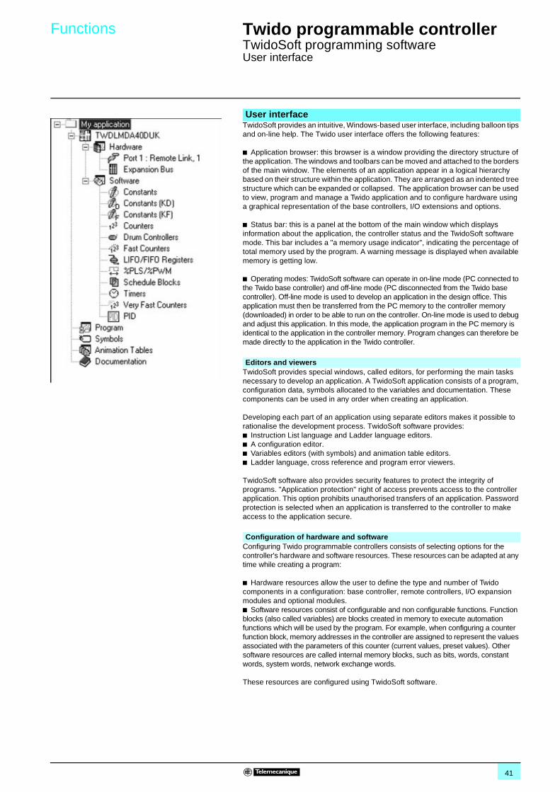
41
Functions 0 Twido programmable controller 0
TwidoSoft programming softwareUser interface
TwidoSoft provides an intuitive, Windows-based user interface, including balloon tips and on-line help. The Twido user interface offers the following features:
b Application browser: this browser is a window providing the directory structure of the application. The windows and toolbars can be moved and attached to the borders of the main window. The elements of an application appear in a logical hierarchy based on their structure within the application. They are arranged as an indented tree structure which can be expanded or collapsed. The application browser can be used to view, program and manage a Twido application and to configure hardware using a graphical representation of the base controllers, I/O extensions and options.
b Status bar: this is a panel at the bottom of the main window which displays information about the application, the controller status and the TwidoSoft software mode. This bar includes a "a memory usage indicator", indicating the percentage of total memory used by the program. A warning message is displayed when available memory is getting low.
b Operating modes: TwidoSoft software can operate in on-line mode (PC connected to the Twido base controller) and off-line mode (PC disconnected from the Twido base controller). Off-line mode is used to develop an application in the design office. This application must then be transferred from the PC memory to the controller memory (downloaded) in order to be able to run on the controller. On-line mode is used to debug and adjust this application. In this mode, the application program in the PC memory is identical to the application in the controller memory. Program changes can therefore be made directly to the application in the Twido controller.
TwidoSoft provides special windows, called editors, for performing the main tasks necessary to develop an application. A TwidoSoft application consists of a program, configuration data, symbols allocated to the variables and documentation. These components can be used in any order when creating an application.
Developing each part of an application using separate editors makes it possible to rationalise the development process. TwidoSoft software provides: b Instruction List language and Ladder language editors. b A configuration editor. b Variables editors (with symbols) and animation table editors.b Ladder language, cross reference and program error viewers.
TwidoSoft software also provides security features to protect the integrity of programs. "Application protection" right of access prevents access to the controller application. This option prohibits unauthorised transfers of an application. Password protection is selected when an application is transferred to the controller to make access to the application secure.
Configuring Twido programmable controllers consists of selecting options for the controller's hardware and software resources. These resources can be adapted at any time while creating a program:
b Hardware resources allow the user to define the type and number of Twido components in a configuration: base controller, remote controllers, I/O expansion modules and optional modules.b Software resources consist of configurable and non configurable functions. Function blocks (also called variables) are blocks created in memory to execute automation functions which will be used by the program. For example, when configuring a counter function block, memory addresses in the controller are assigned to represent the values associated with the parameters of this counter (current values, preset values). Other software resources are called internal memory blocks, such as bits, words, constant words, system words, network exchange words.
These resources are configured using TwidoSoft software.
User interface
Editors and viewers
Configuration of hardware and software
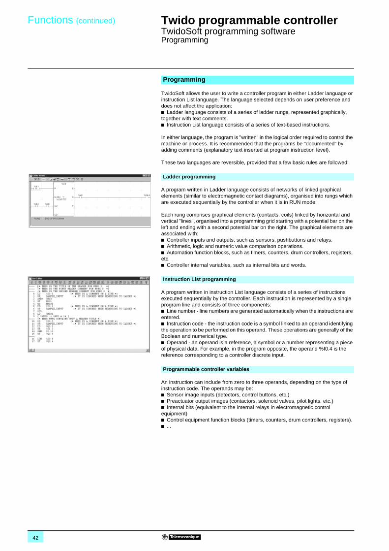
42
Functions (continued) 0 Twido programmable controller 0
TwidoSoft programming softwareProgramming
TwidoSoft allows the user to write a controller program in either Ladder language or instruction List language. The language selected depends on user preference and does not affect the application: b Ladder language consists of a series of ladder rungs, represented graphically, together with text comments. b Instruction List language consists of a series of text-based instructions.
In either language, the program is "written" in the logical order required to control the machine or process. It is recommended that the programs be "documented" by adding comments (explanatory text inserted at program instruction level).
These two languages are reversible, provided that a few basic rules are followed:
A program written in Ladder language consists of networks of linked graphical elements (similar to electromagnetic contact diagrams), organised into rungs which are executed sequentially by the controller when it is in RUN mode.
Each rung comprises graphical elements (contacts, coils) linked by horizontal and vertical "lines", organised into a programming grid starting with a potential bar on the left and ending with a second potential bar on the right. The graphical elements are associated with: b Controller inputs and outputs, such as sensors, pushbuttons and relays.b Arithmetic, logic and numeric value comparison operations.b Automation function blocks, such as timers, counters, drum controllers, registers, etc.b Controller internal variables, such as internal bits and words.
A program written in instruction List language consists of a series of instructions executed sequentially by the controller. Each instruction is represented by a single program line and consists of three components:b Line number - line numbers are generated automatically when the instructions are entered.b Instruction code - the instruction code is a symbol linked to an operand identifying the operation to be performed on this operand. These operations are generally of the Boolean and numerical type.b Operand - an operand is a reference, a symbol or a number representing a piece of physical data. For example, in the program opposite, the operand %I0.4 is the reference corresponding to a controller discrete input.
An instruction can include from zero to three operands, depending on the type of instruction code. The operands may be:b Sensor image inputs (detectors, control buttons, etc.)b Preactuator output images (contactors, solenoid valves, pilot lights, etc.)b Internal bits (equivalent to the internal relays in electromagnetic control equipment)b Control equipment function blocks (timers, counters, drum controllers, registers).b ...
Programming
Ladder programming
Instruction List programming
Programmable controller variables
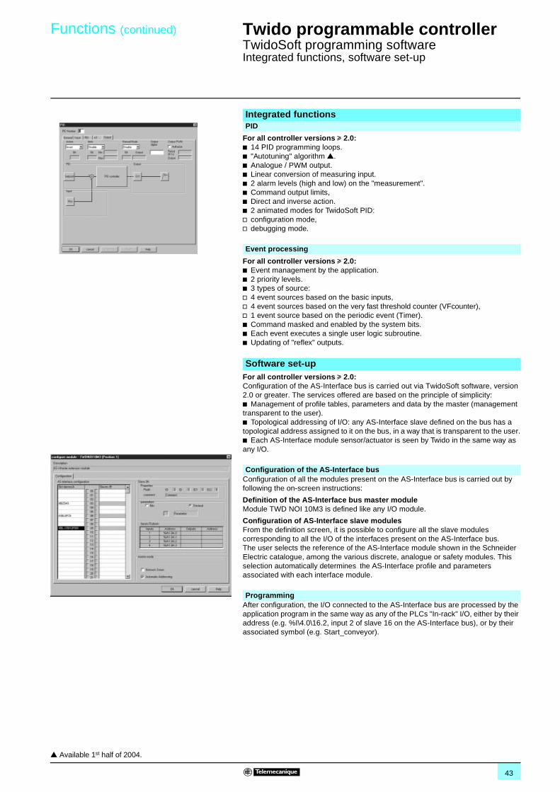
43
Functions (continued) 0 Twido programmable controller 0
TwidoSoft programming softwareIntegrated functions, software set-up
For all controller versions u 2.0:b 14 PID programming loops.b "Autotuning" algorithm r.b Analogue / PWM output.b Linear conversion of measuring input.b 2 alarm levels (high and low) on the "measurement".b Command output limits,b Direct and inverse action.b 2 animated modes for TwidoSoft PID:v configuration mode,v debugging mode.
For all controller versions u 2.0:b Event management by the application.b 2 priority levels.b 3 types of source:v 4 event sources based on the basic inputs,v 4 event sources based on the very fast threshold counter (VFcounter),v 1 event source based on the periodic event (Timer).b Command masked and enabled by the system bits.b Each event executes a single user logic subroutine.b Updating of "reflex" outputs.
For all controller versions u 2.0:Configuration of the AS-Interface bus is carried out via TwidoSoft software, version 2.0 or greater. The services offered are based on the principle of simplicity:b Management of profile tables, parameters and data by the master (management transparent to the user).b Topological addressing of I/O: any AS-Interface slave defined on the bus has a topological address assigned to it on the bus, in a way that is transparent to the user.b Each AS-Interface module sensor/actuator is seen by Twido in the same way as any I/O.
Configuration of all the modules present on the AS-Interface bus is carried out by following the on-screen instructions:
Definition of the AS-Interface bus master module Module TWD NOI 10M3 is defined like any I/O module.
Configuration of AS-Interface slave modulesFrom the definition screen, it is possible to configure all the slave modules corresponding to all the I/O of the interfaces present on the AS-Interface bus. The user selects the reference of the AS-Interface module shown in the Schneider Electric catalogue, among the various discrete, analogue or safety modules. This selection automatically determines the AS-Interface profile and parameters associated with each interface module.
After configuration, the I/O connected to the AS-Interface bus are processed by the application program in the same way as any of the PLCs "In-rack" I/O, either by their address (e.g. %I\4.0\16.2, input 2 of slave 16 on the AS-Interface bus), or by their associated symbol (e.g. Start_conveyor).
Integrated functionsPID
Event processing
Software set-up
Configuration of the AS-Interface bus
Programming
r Available 1st half of 2004.
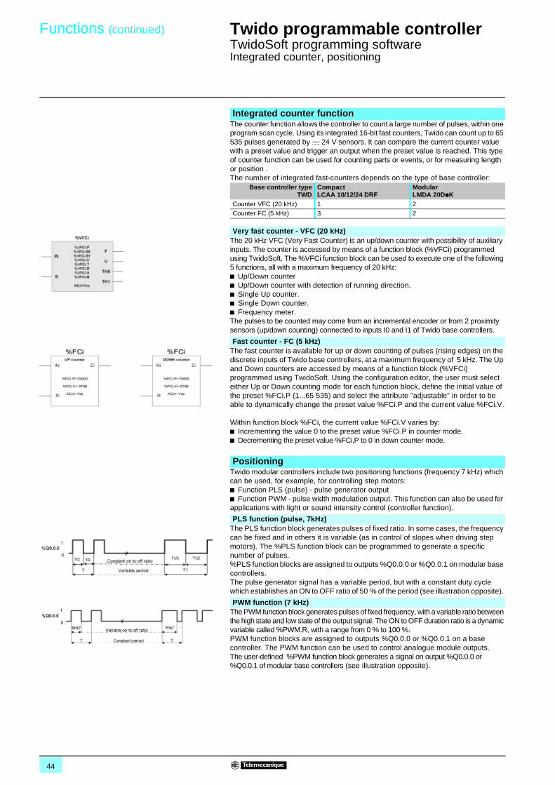
44
Functions (continued) 0 Twido programmable controller 0
TwidoSoft programming softwareIntegrated counter, positioning
The counter function allows the controller to count a large number of pulses, within one program scan cycle. Using its integrated 16-bit fast counters, Twido can count up to 65 535 pulses generated by c 24 V sensors. It can compare the current counter value with a preset value and trigger an output when the preset value is reached. This type of counter function can be used for counting parts or events, or for measuring length or position .The number of integrated fast-counters depends on the type of base controller:
The 20 kHz VFC (Very Fast Counter) is an up/down counter with possibility of auxiliary inputs. The counter is accessed by means of a function block (%VFCi) programmed using TwidoSoft. The %VFCi function block can be used to execute one of the following 5 functions, all with a maximum frequency of 20 kHz:b Up/Down counterb Up/Down counter with detection of running direction.b Single Up counter.b Single Down counter.b Frequency meter.The pulses to be counted may come from an incremental encoder or from 2 proximity sensors (up/down counting) connected to inputs I0 and I1 of Twido base controllers.
The fast counter is available for up or down counting of pulses (rising edges) on the discrete inputs of Twido base controllers, at a maximum frequency of 5 kHz. The Up and Down counters are accessed by means of a function block (%VFCi) programmed using TwidoSoft. Using the configuration editor, the user must select either Up or Down counting mode for each function block, define the initial value of the preset %FCi.P (1...65 535) and select the attribute "adjustable" in order to be able to dynamically change the preset value %FCi.P and the current value %FCi.V.
Within function block %FCi, the current value %FCi.V varies by:b Incrementing the value 0 to the preset value %FCi.P in counter mode.b Decrementing the preset value %FCi.P to 0 in down counter mode.
Twido modular controllers include two positioning functions (frequency 7 kHz) which can be used, for example, for controlling step motors:b Function PLS (pulse) - pulse generator output b Function PWM - pulse width modulation output. This function can also be used for applications with light or sound intensity control (controller function).
The PLS function block generates pulses of fixed ratio. In some cases, the frequency can be fixed and in others it is variable (as in control of slopes when driving step motors). The %PLS function block can be programmed to generate a specific number of pulses. %PLS function blocks are assigned to outputs %Q0.0.0 or %Q0.0.1 on modular base controllers. The pulse generator signal has a variable period, but with a constant duty cycle which establishes an ON to OFF ratio of 50 % of the period (see illustration opposite).
The PWM function block generates pulses of fixed frequency, with a variable ratio between the high state and low state of the output signal. The ON to OFF duration ratio is a dynamic variable called %PWM.R, with a range from 0 % to 100 %.PWM function blocks are assigned to outputs %Q0.0.0 or %Q0.0.1 on a base controller. The PWM function can be used to control analogue module outputs.The user-defined %PWM function block generates a signal on output %Q0.0.0 or %Q0.0.1 of modular base controllers (see illustration opposite).
Integrated counter function
Base controller typeTWD
CompactLCAA 10/12/24 DRF
ModularLMDA 20DpK
Counter VFC (20 kHz) 1 2Counter FC (5 kHz) 3 2
Very fast counter - VFC (20 kHz)
Fast counter - FC (5 kHz)
Positioning
PLS function (pulse, 7kHz)
PWM function (7 kHz)
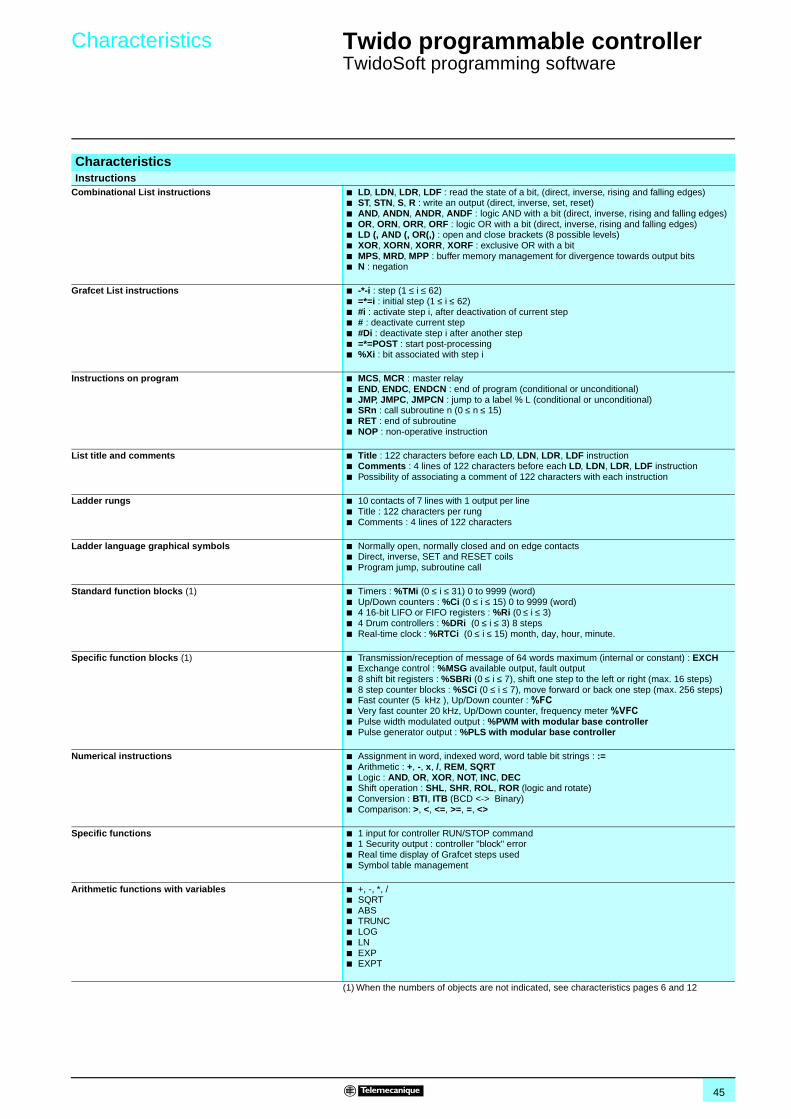
45
Characteristics 0 Twido programmable controller 0
TwidoSoft programming software
CharacteristicsInstructions
Combinational List instructions b LD, LDN, LDR, LDF : read the state of a bit, (direct, inverse, rising and falling edges)b ST, STN, S, R : write an output (direct, inverse, set, reset)b AND, ANDN, ANDR, ANDF : logic AND with a bit (direct, inverse, rising and falling edges)b OR, ORN, ORR, ORF : logic OR with a bit (direct, inverse, rising and falling edges)b LD (, AND (, OR(,) : open and close brackets (8 possible levels)b XOR, XORN, XORR, XORF : exclusive OR with a bitb MPS, MRD, MPP : buffer memory management for divergence towards output bitsb N : negation
Grafcet List instructions b -*-i : step (1 ≤ i ≤ 62)b =*=i : initial step (1 ≤ i ≤ 62)b #i : activate step i, after deactivation of current stepb # : deactivate current stepb #Di : deactivate step i after another stepb =*=POST : start post-processingb %Xi : bit associated with step i
Instructions on program b MCS, MCR : master relayb END, ENDC, ENDCN : end of program (conditional or unconditional)b JMP, JMPC, JMPCN : jump to a label % L (conditional or unconditional)b SRn : call subroutine n (0 ≤ n ≤ 15)b RET : end of subroutineb NOP : non-operative instruction
List title and comments b Title : 122 characters before each LD, LDN, LDR, LDF instructionb Comments : 4 lines of 122 characters before each LD, LDN, LDR, LDF instructionb Possibility of associating a comment of 122 characters with each instruction
Ladder rungs b 10 contacts of 7 lines with 1 output per lineb Title : 122 characters per rungb Comments : 4 lines of 122 characters
Ladder language graphical symbols b Normally open, normally closed and on edge contactsb Direct, inverse, SET and RESET coilsb Program jump, subroutine call
Standard function blocks (1) b Timers : %TMi (0 ≤ i ≤ 31) 0 to 9999 (word)b Up/Down counters : %Ci (0 ≤ i ≤ 15) 0 to 9999 (word)b 4 16-bit LIFO or FIFO registers : %Ri (0 ≤ i ≤ 3)b 4 Drum controllers : %DRi (0 ≤ i ≤ 3) 8 stepsb Real-time clock : %RTCi (0 ≤ i ≤ 15) month, day, hour, minute.
Specific function blocks (1) b Transmission/reception of message of 64 words maximum (internal or constant) : EXCHb Exchange control : %MSG available output, fault outputb 8 shift bit registers : %SBRi (0 ≤ i ≤ 7), shift one step to the left or right (max. 16 steps)b 8 step counter blocks : %SCi (0 ≤ i ≤ 7), move forward or back one step (max. 256 steps)b Fast counter (5 kHz ), Up/Down counter : %FC b Very fast counter 20 kHz, Up/Down counter, frequency meter %VFC b Pulse width modulated output : %PWM with modular base controllerb Pulse generator output : %PLS with modular base controller
Numerical instructions b Assignment in word, indexed word, word table bit strings : :=b Arithmetic : +, -, x, /, REM, SQRTb Logic : AND, OR, XOR, NOT, INC, DECb Shift operation : SHL, SHR, ROL, ROR (logic and rotate)b Conversion : BTI, ITB (BCD <-> Binary)b Comparison: >, <, <=, >=, =, <>
Specific functions b 1 input for controller RUN/STOP commandb 1 Security output : controller "block" errorb Real time display of Grafcet steps usedb Symbol table management
Arithmetic functions with variables b +, -, *, /b SQRTb ABSb TRUNCb LOGb LNb EXPb EXPT
(1) When the numbers of objects are not indicated, see characteristics pages 6 and 12
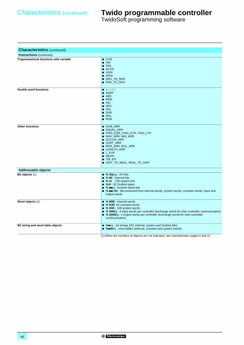
46
Characteristics (continued) 0 Twido programmable controller 0
TwidoSoft programming software
(1) When the numbers of objects are not indicated, see characteristics pages 6 and 12
Characteristics (continued)
Instructions (continued) Trigonometrical functions with variable b COS
b SINb TANb ACOSb ASINb ATANb DEG_TO_RADb RAD_TO_DEG
Double word functions b +, -, *, /b SQRTb ABSb REMb INCb DECb SHLb SHRb ROLb ROR
Other functions b SUM_ARRb EQUAL_ARRb FIND_EQR_FIND_GTR, FIND_LTRb MAX_ARR, MIN_ARRb OCCUR_ARRb SORT_ARRb ROR_ARR, ROL_ARRb LENGTH_ARRb L_KUPb MEANb ITB, BTIb DINT_TO_REAL, REAL_TO_DINT
Addressable objectsBit objects (1) b % I/Qx.y : I/O bits
b % Mi : internal bitsb % Si : 128 system bitsb %Xi : 62 Grafcet stepsb % ppi.j : function block bitsb % ppi:Xk : bits extracted from internal words, system words, constant words, input and
output words
Word objects (1) b % MWi : internal wordsb % KWi: 64 constant wordsb % SWi : 128 system wordsb % INWi.j : 4 input words per controller (exchange words for inter-controller communication)b % QNWi.j : 4 output words per controller (exchange words for inter-controller
communication)
Bit string and word table objects b %pi:L : bit strings (I/O, internal, system and Grafcet bits)b %pWi:L : word tables (internal, constant and system words)
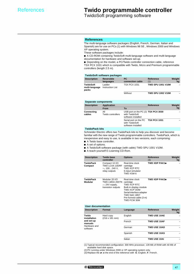
47
References 0 Twido programmable controller 0
TwidoSoft programming software
The multi-language software packages (English, French, German, Italian and Spanish) are for use on PCs (1) with Windows 98 SE , Windows 2000 and Windows XP operating system.These software packages include:b A CD-ROM containing TwidoSoft multi-language software and multi-language documentation for hardware and software set-up.b Depending on the model, a PC/Twido controller connection cable, reference TSX PCX 1031 which is compatible with Twido, Micro and Premium programmable controllers (length 2.5 m).
Schneider Electric offers two TwidoPack kits to help you discover and become familiar with the new range of Twido programmable controllers. TwidoPack, which is inexpensive and easy to use, is available in two versions, each comprising:b A Twido base controller.b A set of options.b A TwidoSoft software package (with cable) TWD SPU 1001 V10M.b A teach-yourself E-Learning CD-Rom.
References
TwidoSoft software packagesDescription Reversible
languagesPC connection cable
Reference(1)
Weightkg
TwidoSoft multi-language packs
LadderInstruction List
TSX PCX 1031 TWD SPU 1001 V10M –
Without TWD SPU 1002 V10M –
Separate componentsDescription Application Reference Weight
kgFrom ToConnecting cables
All Twido controllers
USB port on the PC (2) with TwidoSoft software installed
TSX PCX 3030 –
Serial port on the PC with TwidoSoft software installed
TSX PCX 1031 –
TwidoPack kits
Description Twido base controller
Options Reference(3)
Weightkg
TwidoPack Compact
Compact 10 I/O TWD LCAA 10DRF a 100…240 V, relay outputs
Real-time clock cartridge TWD XCP RTC6-input simulator TWD XSM 6
TWD XDP PAK1p –
TwidoPack Modular
Modular 20 I/O TWD LMDA 20DTK c 24V supply, transistor outputs
Real-time clock cartridge TWD XCP RTCBuilt-in display module TWD XCP ODMSerial interface adapter TWD NAC 485TPre-formed cable (3 m) TWD FCW 30M
TWD XDP PAK2p –
User documentationDescription Format Language Reference Weight
kgTwido installation and set-up manualsHardware and software
Hard copy(216 x 181 mm)
English TWD USE 10AE –
French TWD USE 10AF –
German TWD USE 10AD –
Spanish TWD USE 10AS –
Italian TWD USE 10AI –
(1) Typical recommended configuration: 300 MHz processor, 128 Mb of RAM with 40 Mb of available hard disk space.
(2) PC running under Windows 2000 or XP operating system only.(3) Replace the p at the end of the reference with E: English, F: French.
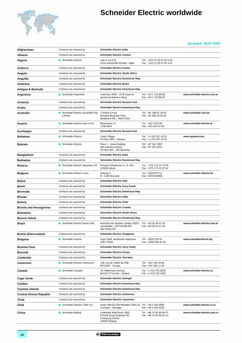
48
Schneider Electric worldwide 0
Afghanistan Contacts are assured by Schneider Electric India
Albania Contacts are assured by Schneider Electric Austria
Algeria b Schneider Electric voie A Lot C22Zone industrielle Rouiba - Alger
Tel. : +213 21 92 97 02 à 09Fax : +213 21 92 97 00 à 01
Andorra Contacts are assured by Schneider Electric France
Angola Contacts are assured by Schneider Electric South Africa
Anguilla Contacts are assured by Schneider Electric Dominican Rep.
Antartica Contacts are assured by Schneider Electric Brazil
Antigua & Barbuda Contacts are assured by Schneider Electric Dominican Rep.
Argentina b Schneider Argentina Viamonte 2850 - 1678 Caseros(provincia Buenos Aires)
Tel.: +54 1 716 88 88Fax: +54 1 716 88 33
www.schneider-electric.com.ar
Armenia Contacts are assured by Schneider Electric Russian Fed.
Aruba Contacts are assured by Schneider Electric Dominican Rep.
Australia b Schneider Electric (Australia) Pty. Limited
2 Solent CircuitNorwest Business ParkBaulkham Hill _ NSW 2153
Tel.: +61 298 51 28 00Fax: +61 296 29 83 40
www.schneider.com.au
Austria b Schneider Austria Ges.m.b.H. Birostrasse 111239 Wien
Tel.: +431 610 540Fax: +431 610 54 54
www.schneider-electric.at
Azerbaijan Contacts are assured by Schneider Electric Russian Fed.
Bahamas b Schneider Electric Union VillagePO Box 3901 - Nassau
Tel. : +1 242 327 42 91Fax : +1 242 327 42 91
www.squared.com
Bahrain b Schneider Electric Floor 1 - Juma BuildingAbu Horaira AvenuePO Box 355 - 304 Manama
Tel.: +97 322 7897Fax: +97 321 8313
Bangladesh Contacts are assured by Schneider Electric India
Barbados Contacts are assured by Schneider Electric Dominican Rep.
Belarus b Schneider Electric Industries SA Prospect Macherova 5, of. 202220004 Minsk
Tel. : +375 172 23 75 50Fax : +375 172 23 97 61
Belgium b Schneider Electric nv/sa Dieweg 3B - 1180 Brussels
Tel.: +3223737711Fax: +3223753858
www.schneider-electric.be
Belize Contacts are assured by Schneider Electric USA
Benin Contacts are assured by Schneider Electric Ivory Coast
Bermuda Contacts are assured by Schneider Electric Dominican Rep.
Bhutan Contacts are assured by Schneider Electric India
Bolivia Contacts are assured by Schneider Electric Chile
Bosnia and Herzegovina Contacts are assured by Schneider Electric Croatia
Botswana Contacts are assured by Schneider Electric South Africa
Bouvet island Contacts are assured by Schneider Electric Dominican Rep.
Brazil b Schneider Electric Brazil Ltda. Avenida Das Nações Unidas 23223Jurubatuba - CEP 04795-907São Paulo-SP
Tel.: +55 55 24 52 33Fax: +55 55 22 51 34
www.schneider-electric.com.br
Brunei (Darussalam) Contacts are assured by Schneider Electric Singapore
Bulgaria b Schneider Electric Expo 2000, Boulevard Vaptzarov1407 Sofiav
Tel.: +3592 919 42Fax: +3592 962 44 39
www.schneiderelectric.bg
Burkina Faso Contacts are assured by Schneider Electric Ivory Coast
Burundi Contacts are assured by Schneider Electric Kenya
Cambodia Contacts are assured by Schneider Electric Viet Nam
Cameroon b Schneider Electric Cameroon 166, rue de l'Hôtel de VilleBP12087 - Douala
Tel.: +237 343 38 84Fax: +237 343 11 94
Canada b Schneider Canada 19, Waterman AvenueM4 B1Y2 Toronto - Ontario
Tel.: +1 416 752 8020Fax: +1 416 752 4203
www.schneider-electric.ca
Cape Verde Contacts are assured by Schneider Electric Senegal
Caribee Contacts are assured by Schneider Electric Dominican Rep.
Cayman islands Contacts are assured by Schneider Electric Dominican Rep.
Central African Republic Contacts are assured by Schneider Electric Cameroon
Chad Contacts are assured by Schneider Electric Cameroon
Chile b Schneider Electric Chile S.A. Avda. Pdte Ed. Frei Montalva, 6001-31 Conchali - Santiago
Tel.: +56 2 444 3000Fax: +56 2 423 9335
www.schneider-electric.co.cl
China b Schneider Beijing Landmark bldg-Room 18018 North Dong Sanhuan RdChaoyang District 100004 Beijing
Tel.: +86 10 65 90 69 07Fax: +86 10 65 90 00 13
www.schneider-electric.com.cn
Up-dated: 28-07-2003
Schneider Electric worldwide 0
Up-dated: 28-07-2003
49
Christmas island Contacts are assured by Schneider Electric Australia
Cocos (Keeling) islands Contacts are assured by Schneider Electric Australia
Colombia b Schneider Electric de Colombia S.A.
Calle 45A #102-48Bogota DC
Tel.: +57 1 426 97 00Fax: +57 1 426 97 40
Comoros Contacts are assured by Schneider Electric la Reunion
Congo Contacts are assured by Schneider Electric Cameroon
Cook islands Contacts are assured by Schneider Electric Australia
Costa Rica b Schneider Centroamérica Ltda. 1.5 kmts oeste de la Embajada Americana,Pavas, San José, Costa Rica C.A.Apartado: 4123-1000 San Jose
Tel.: +506 232-60-55Fax: +506 232-04-26
www.schneider-ca.com
Croatia b Schneider Electric SA Fallerovo Setaliste 22HR - 10000 Zagreb
Tel.: +385 1 367 100Fax: +385 1 367 111
Cuba b Schneider Electric Bureau de Liaison de La HavaneCalle 36- N°306-Apto1Entre 3ra y 5ta Avenida MiramarPlaya Habana
Tel.: +53 724 15 59Fax: +53 724 12 17
Cyprus b Schneider Electric Cyprus 28 General Timayia AvenueKyriakos Building, Block #A301Larnaca 6046
Tel.: +00357 248 12646Fax: +00357 246 37382
Czech Republic b Schneider Electric CZ, s.r.o. Thámova 13Praha 8 - 186 00
Tel.: +420 2 810 88 111Fax: +420 2 24 81 08 49
www.schneider-electric.cz
Democratic Rep. of Congo Contacts are assured by Schneider Electric Cameroon
Denmark b Schneider Electric A/S Baltorpbakken 14DK-2750 Ballerup
Tel.: +45 44 73 78 88Fax: +45 44 68 5255
www.schneider-electric.dk
Djibouti Contacts are assured by Schneider Electric Egypt
Dominican Republic b Schneider Electric Calle Jacinto ManonEsq. Federico GeraldinoEdificio D' Roca Plaza Suite 402,Ens. Paraiso - Santo Domingo
Tel.: +1 809 334 66 63Fax: +1 809 334 66 68
Ecuador b Schneider Electric Ecuador SA Av.Republica del Salvador 1082 y Nac Edificio Mansion Blanca-Quito
Tel. : +593 2 224 42 42Fax : +593 2 224 42 94
Egypt b Schneider Electric Egypt sae 68, El Tayaran StreetNasr City, 11371 - Cairo
Tel.: +20 24 01 01 19Fax: +20 24 01 66 87
www.schneider.com.eg
El Salvador Contacts are assured by Schneider Electric USA
Equatorial Guinea Contacts are assured by Schneider Electric Cameroon
Eritrea Contacts are assured by Schneider Electric Egypt
Estonia b Lexel Electric Ehitajate tee 110EE 12618 Talinn
Tel. : +372 650 97 00Fax : +372 650 97 22
Ethiopia Contacts are assured by Schneider Electric Egypt
Falkland islands Contacts are assured by Schneider Electric Brazil
Faroe islands Contacts are assured by Schneider Electric Australia
Fiji Contacts are assured by Schneider Electric Australia
Finland b Schneider Electric Oy Sinimäentie 1402630 Espoo
Tel. : +358 9 527 000Fax : +358 9 5270 0376
www.schneider-electric.fi
France b Schneider Electric SA 5, rue Nadar92500 Rueil Malmaison
Tel.: +33 (0)1 41 29 82 00Fax: +33 (0)1 47 51 80 20
www.schneider-electric.fr
French Polynesia Contacts are assured by Schneider Electric Australia
French West Indies Contacts are assured by Schneider Electric Dominican Rep.
Gabon Contacts are assured by Schneider Electric Cameroon
Gambia Contacts are assured by Schneider Electric Senegal
Georgia Contacts are assured by Schneider Electric Russian Fed.
Germany b Schneider Electric GmbH Gothaer Straße 29D-40880 Ratingen
Tel.: +49210 240 40Fax: +492 10 240 49 256
www.schneiderelectric.de
Ghana b Schneider Electric Ghana PMB Kia3rd Floor Opeibea HouseAirport Commercial CenterLiberation road - Accra
Tel. : +233 21 70 11 687Fax : +233 21 77 96 22
Gilbraltar Contacts are assured by Schneider Electric Spain
Greece b Schneider Electric AE 14th km - RN Athens-LamiaGR - 14564 Kifissia
Tel.: +302 106 29 52 00Fax: +302 106 29 52 10
www.schneider-electric.com.gr
Greenland Contacts are assured by Schneider Electric United States
Grenada Contacts are assured by Schneider Electric Dominican Rep.
Guadeloupe Contacts are assured by Schneider Electric Martinique
Guam Contacts are assured by Schneider Electric Australia
Schneider Electric worldwide 0
Up-dated: 28-07-2003
50
Guatemala Contacts are assured by Schneider Electric United States
Guinea-Bissau Contacts are assured by Schneider Electric Sénégal
Guinea Contacts are assured by Schneider Electric Ivory Coast
Guyana Contacts are assured by Schneider Electric United States
Haiti Contacts are assured by Schneider Electric Dominican Rep.
Heard & Mac Donald isl. Contacts are assured by Schneider Electric Australia
Honduras Contacts are assured by Schneider Electric United States
Hong Kong b Schneider Electric (Hong Kong) Ltd
Room 3108-28, 31th Floor,Sun Hung Kai Centre,30 Harbour Road, Wanchai
Tel.: +852 25 65 06 21Fax: +852 28 11 10 29
Hungary b Schneider Electric Hungária Villamossági Rt.
Fehérvári út 108 – 112H-1116 Budapest
Tel.: +36 1 382 26-06Fax: +36 1 206 1429
www.schneider-electric.hu
Iceland Contacts are assured by Schneider Electric Denmark
India b Schneider Electric India Max House, 1 Dr Jha Marg, Okhla110 020 New Dehli
Tel. : +91 11 631 85 84Tel. : +91 11 631 71 61
www.schneiderelectric-in.com
Indonesia b P.T. Schneider Indonesia Ventura Building 7th FloorJalan R.A. Kartini Kav.26Cilandak - 12430 Jakarta
Tel.: +62 +21 750 44 06Fax: +62 +21 750 44 15/ 16
www.schneider-electric.co.id
Iran (Islamic Republic of) b Telemecanique Iran 1047 Avenue VALI ASSRP.O. Box 15875-3547 15116 Teheran
Tel.: +98 218 71 01 42Fax: +98 218 71 81 87
Irak b Schneider Electric Industries SA 38050 Grenoble Cedex 9 Tel.: +33 04 76 60 54 27Fax: +33 04 76 60 56 60
Ireland b Schneider Electric Ireland Maynooth RoadCellbridge - Co. Kildare
Tel.: +353+0 1 6012200Fax: +353+0 1 6012201
www.schneiderelectric.ie
Italy b Schneider Electric S.p.A. Centro Direzionale ColleoniPalazzo Sirio - Viale Colleoni, 720041 Agrate Brianza (Mi)
Tel.: +39 39 655 8111Fax: +39 39 605 6237
www.schneiderelectric.it
Ivory Coast b Schneider Electric Afrique de l'Ouest
Rue Pierre et Marie Curie18 BP 2027 Abidjan 18
Tel.: +225 21 75 00 10Fax: +225 21 75 00 30
Jamaica b Schneider Electric Shop#5, Plaza Dunrobin30 Dunrobin Avenue - Kingstown
Tel. : +1876 755 41 27Tel. : +931 87 74
Japan b Schneider Electric Japan Ltd Torigoe F. Bldg1-8-2, TorigoeTaito-Ku - 111-0054 Tokyo
Tel.: +81 358 35 35 81Fax: +81 358 35 35 85
www.schneider-electric.co.jp
Jordan b Schneider Electric Industr. Jordan Jordan University StreetAbu Al Haj Commercial Complex2nd Floor - Office # 202 - Amman
Tel.: 962 65 16 78 87Fax: 962 65 16 79 1
Kazakstan b Schneider Electric Kazakhstan Liaison Office
Prospekt Abaia 157 off 9480009 Almaty
Tel. : +7 327 250 93 88Tel. : +7 327 250 63 70
Kenya b Schneider East Africa Power Technics ComplexMonbasa Road - PO Box 46345Nairobi
Tel. : +254 2.824.156Fax : +254 2.824.157
Kiribati Contacts are assured by Schneider Electric Australia
Korea b Schneider Electric Korea Ltd 3Floor, Cheil Bldg., 94-46, 7-KaYoungdeungpodong, Youngdeungpo-ku150-037 Seoul
Tel. : +82 2 2630 9700Fax : +82 2 2630 9800
www.csinfo.co.kr/schneider/
Kurdistan Contacts are assured by Schneider Electric Russian Fed.
Kuwait b Schneider Electric Kuwait Al Gaas Tower - Sharq 2nd FloorPO Box 20092 - 13 061 Safat
Tel.: +965 240 75 46Fax: +965 240 75 06
Kyrgyz Republic Contacts are assured by Schneider Electric Russian Fed.
Laos Contacts are assured by Schneider Electric Thailand
Latvia b Lexel Electric 60A A.Deglava str.LV1035 Riga
Tel. : +371 780 23 74/75Fax : +371 754 62 80
Lebanon b Schneider Electric Liban Tabaris, Avenue Charles MalekImmeuble Ashada, 8P.O. Box 166223 - Beyrouth
Tel. : +961 1 20 46 20Tel. : +961 1 20 31 19
Lesotho Contacts are assured by Schneider Electric South Africa
Liberia Contacts are assured by Schneider Electric Ghana
Libya Contacts are assured by Schneider Electric Tunisia
Liechtenstein Contacts are assured by Schneider Electric Switzerland
Lithuania b Lexel Electric 44, Verkiu str.LT-2012 Vilnius
Tel. : +370 278 59 59/61Fax : +370 278 59 60
Loro Sae Contacts are assured by Schneider Electric Australia
Luxembourg b Schneider Electric Industrie SAS Agence de Metz1, Rue Graham Bell - BP n° 3519057075 Metz cedex 3 - France
Tel.: 33 03 87 39 06 03Fax: 33 03 87 74 25 96
www.schneider-electric.fr
Schneider Electric worldwide 0
Up-dated: 28-07-2003
51
Macau Contacts are assured by Schneider Electric China
Macedonia Contacts are assured by Schneider Electric Bulgaria
Madagascar Contacts are assured by Schneider Electric la Reunion
Malawi Contacts are assured by Schneider Electric South Africa
Malaysia b Schneider Electric (Malaysia) Sdn Bhd
No.11 Jalan U1/19, Seksyen U1Hicom-Glenmarie Industrial Park40150 Shah AlamSelangor Darul Ehsan
Tel. : (603) 7883 6333Fax : (603) 7883 6188
www.schneider-electric.com.my
Maldives Contacts are assured by Schneider Electric Reunion
Mali Contacts are assured by Schneider Electric Senegal
Malta Contacts are assured by Schneider Electric Tunisia
Marshall islands Contacts are assured by Schneider Electric Australia
Martinique b Schneider Electric Schneider ElectricImmeuble Cottrell - ZI de la Lézarde97232 Le Lamentin
Tel.: +05 96 51 06 00Fax: +05 96 51 11 26
Mauritania Contacts are assured by Schneider Electric Senegal
Mauritius b Schneider Electric Route côtièreCalodyne - Mauritius
Tel.: 230 282 18 83Fax: 230 282 18 84
Mayotte Contacts are assured by Schneider Electric Reunion
Mexico b Groupe Schneider Mexico Calz. Rojo Gomez N° 1121-ACol. Guadalupe del MoralMéxico, D.F. - C.P. 09300
Tel.: +525 686 30 00Fax: +525 686 24 09
www.schneider-electric.com.mx
Micronesia Contacts are assured by Schneider Electric Australia
Moldova Contacts are assured by Schneider Electric Romania
Monaco Contacts are assured by Schneider Electric France
Mongolia Contacts are assured by Schneider Electric Russian Fed.
Montserrat Contacts are assured by Schneider Electric Dominican Rep.
Morocco b Schneider Electric Morocco 26, rue Ibnou KhalikaneQuartier Palmiers20100 Casablanca
Tel.: +212 299 08 48 to 57Fax: +212 299 08 67 and 69
www.schneider.co.ma
Mozambique Contacts are assured by Schneider Electric South Africa
Myanmar Contacts are assured by Schneider Electric Singapore
Namibia Contacts are assured by Schneider Electric South Africa
Nauru Contacts are assured by Schneider Electric Australia
Nepal Contacts are assured by Schneider Electric India
Netherlands b Schneider Electric BV Waarderweg 40 - Postbus 8362003 RV Haarlem
Tel.: +31 23 512 4124Fax: +31 23 512 4100
www.schneider-electric.nl
Netherlands Antilles Contacts are assured by Schneider Electric Dominican Rep.
New Caledonia Contacts are assured by Schneider Electric Australia
New Zealand b Schneider Electric (NZ) Ltd 14 Charann Place AvondaleP.O. Box 15355 - New LynnAuckland
Tel. : +64 9 829 04 90Fax : +64 9 829 04 91
www.schneider-electric.co.nz
Nicaragua Contacts are assured by Schneider Electric United States
Niger Contacts are assured by Schneider Electric Ivory Coast
Nigeria b Schneider Electric Nigeria Limited Biro plaza - 8th Floor - Plot 634Abeyemo Alakija StreetVictoria Islan - Lagos
Tel. : +234 1 2702973Fax : +234 1 2702976
Niue Contacts are assured by Schneider Electric Australia
Norfolk island Contacts are assured by Schneider Electric Australia
North Korea Contacts are assured by Schneider Electric China
Northern Mariana islands Contacts are assured by Schneider Electric Australia
Norway b Schneider Electric Norge A/S Solgaard Skog 2Postboks 128 - 1501 Moss
Tel.: +47 6924 9700Fax: +47 6925 7871
www.schneider-electric.no
Oman b Schneider Electric CA c/o Arab Development CoPO Box 439 - 113 Muscat
Tel.: +968 77 163 64Fax: +968 77 104 49
Pakistan b Schneider Electric Pakistan 43-L, 2nd floor, M.M. Alam Road,Gulberg II - Lahore
Tel.: +92 42 5754471 à 73Fax: +92 42 5754474
Palau Contacts are assured by Schneider Electric Australia
Panama Contacts are assured by Schneider Electric United States
Papua New Guinea Contacts are assured by Schneider Electric Australia
Paraguay Contacts are assured by Schneider Electric Uruguay
Schneider Electric worldwide 0
Up-dated: 28-07-2003
52
Peru b Schneider Electric Peru S.A. Los Telares n°231 Urb. Vulcano, Ate Lima 03
Tel.: +511 348 44 11Fax: +511 348 05 23
www.schneider-electric.com.pe
Philippines b Schneider Electric Philippines, Inc 5th Floor, ALCO Building391 Sen, Gil Puyat AvenueMakati 1209
Tel. : +632 896 6063Fax : +632 896 7229
Pitcairn Contacts are assured by Schneider Electric Australia
Poland b Schneider Electric Polska Sp.zo.o. ul. Lubinowa 4a03-878 - Warszawa
Tel.: +48 22 511 8 200Fax: +48 22 511 8 210
www.schneider-electric.pl
Portugal b Schneider Electric Portugal Av.do Forte, 3Edificio Suécia II, Piso 3-ACP 2028 Carnaxide2795 Linda-A-Velha
Tel.: +351 21 416 5800Fax: +351 21 416 5857
www.schneiderelectric.pt
Puerto Rico Contacts are assured by Schneider Electric United States
Qatar b Schneider Electric Qatar Branch c/o Khalifa BinFahred Al ThaniTrad.and Co - P.O. Box 4484Doha
Tel.: +97 4424358Fax: +97 4424358
Reunion b Schneider Electric Immeuble Futura, 190, rue des 2 canonsBP 646 - 97497 Sainte Clothilde
Tel.: +262 28 14 28Fax: +262 28 39 37
Romania b Schneider Electric Bd Ficusului n°42Apimondia, Corp.A, et.1, Sector 1Bucuresti
Tel.: +401 203 06 50Fax: +401 232 15 98
www.schneider-electric.ro
Russian Federation b Schneider Electric ZAO Enisseyskaya 37129 281 Moscow
Tel.: +7095 797 40 00Fax: +7095 797 40 03
www.schneider-electric.ru
Rwanda Contacts are assured by Schneider Electric Kenya
Samoa Contacts are assured by Schneider Electric Australia
San Marino Contacts are assured by Schneider Electric Italy
Sandwich & Georgia island Contacts are assured by Schneider Electric Australia
Sao Tome & Principe Contacts are assured by Schneider Electric Senegal
Saudi Arabia b Schneider Electric Second Industrial CityP.O. Box 89249 - 11682 Riyadh
Tel.: +966 1 265 1515Fax: +966 1 265 1860
Senegal b Schneider Electric Sénégal BP 15952 - Dakar-FannRond point N'Gor - Dakar
Tel.: +221 820 68 05Fax: +221 820 58 50
Seychelles Contacts are assured by Schneider Electric Reunion
Sierra Leone Contacts are assured by Schneider Electric Ghana
Singapore b Schneider Electric Singapore Pte Ltd
10 Ang Mo Kio Street 65#02-17/20 TechPointSingapore 569059
Tel.: +65 484 78 77Fax: +65 484 78 00
www.schneider-electric.com.sg
Slovak Republic b Schneider Electric Slovakia spol s.r.o.
Borekova 10SK-821 06 Bratislava
Tel. : +02 45 52 40 10 and 40 30Fax : +02 45 52 40 00
www.schneider-electric.sk
Slovenia b Schneider Electric, d.o.o. Dunasjka 471000 Ljubljana
Tel. : +386 1 23 63 555Fax : +386 1 23 63 559
www.schneider-electric.si
Solomon islands Contacts are assured by Schneider Electric Australia
Somalia Contacts are assured by Schneider Electric Egypt
South Africa b Schneider Electric South Africa (PTY) Ltd
Private Bag X139Halfway House1685 - Midrand.
Tel.: +27 11 254 6400Fax: +27 11 315 8830
www.schneider-electric.co.za
Spain b Schneider Electric España, S.A. Pl. Dr. Letamendi, 5-708007 Barcelona
Tel.: +34 93 484 3100Fax: +34 93 484 3308
www.schneiderelectric.es
Sri Lanka b Schneider Electric Industries SA Liaison office SRI LankaLevel 3B Valiant towers46/7 Nawam Mawatha-Colombo 2
Tel. : +94 77 48 54 89 www.schneiderelectric-in.com
St Helena Contacts are assured by Schneider Electric Italy
St Kitts & Nevis Contacts are assured by Schneider Electric Dominican Rep.
St Lucia Contacts are assured by Schneider Electric Dominican Rep.
St Pierre et Miquelon Contacts are assured by Schneider Electric Dominican Rep.
St Vincent & Grenadines Contacts are assured by Schneider Electric Dominican Rep.
Sudan Contacts are assured by Schneider Electric Egypt
Suriname Contacts are assured by Schneider Electric United States
Svalbard & Jan Mayen isl. Contacts are assured by Schneider Electric Denmark
Swaziland Contacts are assured by Schneider Electric South Africa
Sweden b Schneider Electric AB Djupdalsvägen 17/1919129 Sollentuna
Tel.: +46 8 623 84 00Fax: +46 8 623 84 85
www.schneider-electric.se
Switzerland b Schneider Electric (Switzerland) S.A.
Schermenwaldstrasse 11CH - 3063 Ittigen
Tel.: +41 31 917 3333Fax: +41 31 917 3355
www.schneider-electric.ch
Schneider Electric worldwide 0
Up-dated: 28-07-2003
53
Syrian Arab Republic b Schneider Electric Syria Elba Street - MalkiGheibeh and Qassas bldg, 1st floorPO Box 33876-Damascus
Tel. : +963 11 37 49 88 00Fax : +963 11 37 17 55 9
Taiwan, Republic of China b Schneider Electric Taiwan Co Ltd 2FI., N°37, Ji-Hu Road, Nei-Hu Dist.,Taipei 114
Tel. : +886 2 8751 6388Fax : +886 2 8751 6389
www.schneider-electric.com.tw
Tajikistan Contacts are assured by Schneider Electric Russian Fed.
Tanzania, United Rep. of Contacts are assured by Schneider Electric Kenya
Thailand b Schneider (Thailand) Ltd 20th Floor Richmond Building75 Sukhumvit 26 Road, KlongtoeyBangkok 10110
Tel.: +662 204 9888Fax: +662 204 9816
www.schneider-electric.co.th
Togo Contacts are assured by Schneider Electric Ivory Coast
Tokelau Contacts are assured by Schneider Electric Australia
Tonga Contacts are assured by Schneider Electric Australia
Trinidad & Tobago b Schneider Electric 6, 1st Street West Ext.Beaulieu AvenueTrincity Trinidad West Indies
Tel.: 1868 640 42 04Fax: 1868 640 42 04
Tunisia b Schneider Electric Tunisia Rue du Lac Oubeira1053 Les Berges du Lac - Tunis
Tel.: +216 71 960 477Fax: +216 71 960 342
Turkey b Schneider Elektrik Sanayi Ve Ticaret A.S.
Tütüncü Mehmet Efendi Cad. N°:110 Kat 1-2 - 81080 Göztepe – Istanbul
Tel.: +90 21 63 86 95 70 Fax: +90 21 63 86 38 75
www.schneiderelectric.com.tr
Turkmenistan b Schneider Electric Turkmenistan Liaison Office
rue Neitralny Turkmenistan 28,off.326/32774 000 Achgabad
Tel. : +993 12 46 29 52Fax : +993 12 46 29 52
Turks & Caicos islands Contacts are assured by Schneider Electric Dominican Rep.
Tuvalu Contacts are assured by Schneider Electric Australia
Uganda Contacts are assured by Schneider Electric Kenya
Ukraine b Schneider Electric Rue Krechtchalik 2252601 Kiev
Tel.: +380 44 462 04 25Fax: +380 44 462 04 24
www.schneider-electric.com.ua
United Arab Emirates b Schneider Electric Abu Dhabi PO Box 29580Office Floor 2/Lulu StreetAl Marina Plaza TowerAbu Dhabi
Tel.: +9712 6 339444Fax: +9712 6 316606
United Kingdom b Schneider Electric Ltd Braywick House EastWindsor Road - MaidenheadBerkshire SL6 1 DN
Tel.: +44 (0)1 628 508 500Fax: +44 (0)1 628 508 508
www.schneider.co.uk
United States b Schneider Electric North American Division1415 Roselle RoadPalatine - IL 60067
Tel.: +1 847 397 2600Fax: +1 847 925 7500
www.squared.com
Uruguay b Schneider Electric Uruguay S.A. Ramon Masini 3190Montevideo
Tel. : +59 82 707 2392 Fax : +59 82 707 2184
Uzbekistan Contacts are assured by Schneider Electric Russian Fed.
Vanuatu Contacts are assured by Schneider Electric Australia
Vatican city St./Holy See Contacts are assured by Schneider Electric Italy
Venezuela b Schneider Mg SD TE, S.A Calle 162/ Piso 2Edificio Centro CynamidLa Urbina, 1070 - 75319 Caracas
Tel.: +58 2 241 13 44Fax: +58 2 243 60 09
www.schneider-electric.com.ve
Viet Nam b R.R.O. of Schneider Electric Industries S.A.S. in Viet Nam
Unit 2.9, 2nd Floor, e-Town Building364 Cong Hoa StreetTan Binh District - Ho Chi Minh City
Tel.: +84 8 8103 103Fax: +84 8 8120 477
Virgin islands Contacts are assured by Schneider Electric Dominican Rep.
Wallis & Futuna islands Contacts are assured by Schneider Electric Australia
Western Sahara Contacts are assured by Schneider Electric Morocco
Yemen Contacts are assured by Schneider Electric U.A.E.
Yugoslavia b Schneider Electric Jugoslavija d.o.o.
Ratarski put 27d11186 Belgrade
Tel.: +381 11 192 414Fax: +381 11 107 125
Zambia b Schneider Zambia Zambia Officec/o Matipi Craft Center BuildingPlot 1036 - Accra RoadPO Box 22792 - Kitwe
Tel.: +260 222 22 52Fax: +260 222 83 89
Zimbabwe b Schneider Electric Zimbabwe Liaison Office75A Second Street(corner Livingstone Avenue)Harare
Tel.: +263 4 707 179/180Fax: +263 4 707 176
54
0 Twido programmable controllers 0
Community regulations and protective treatment
The opening of European markets implies a harmonization of regulations in the various European Union member states.European Directives are documents used to remove obstacles to the free movement of goods and their application is compulsory in all states of the European Union.Member states are obliged to transcribe each Directive into their national legislation and, at the same time, to withdraw any conflicting regulations.The Directives, particularly those of a technical nature with which we are concerned, only set objectives, called “general requirements”.The manufacturer must take all necessary measures to ensure that his products conform to the requirements of each Directive relating to his equipment.As a general rule, the manufacturer affirms that his product conforms to the necessary requirements of the Directive(s) by applying the e label to his product.e marking is applied to Telemecanique products where relevant.
b e marking on a product means that the manufacturer certifies that his product conforms to the relevant European Directives ; it is necessary in order that a product which is subject to a Directive(s) can be marketed and freely moved within the European Union.b e marking is intended solely for the national authorities responsible for market regulation.
For electrical equipment, only conformity of the product to standards indicates that it is suitable for use, and only a guarantee by a recognised manufacturer can ensure a high level of quality.One or more Directives, as appropriate, may apply to our products, in particular :b The Low Voltage Directive 72/23/EEC amended by Directive 93/68/EEC : e marking under the terms of this Directive could not be applied before 1 January 1995 and is compulsory as of 1 January 1997.b The Electromagnetic Compatibility Directive 89/336/EEC, amended by Directives 92/31/EEC and 93/68/EEC : e marking on the products covered by this Directive has been compulsory since 1 January 1996.
Twido PLCs meet the requirements of “TC” treatment (1).For installations in industrial production workshops or in an environment which corresponds to “TH” treatment (2), Twido PLCs should be enclosed in casings with a minimum of IP 54 protection as prescribed by standards IEC 60 664 and NF C 20 040.Twido PLCs are supplied with an IP 20 protection index. They can therefore be installed without enclosure in locations with restricted access which do not exceed pollution degree 2 (control room which does not contain a machine or dust-producing activity).
(1) “TC” treatment : all climate treatment.(2) “TH” treatment : treatment for hot and humid environments.
Community regulationsEuropean Directives
The significance of e marking
Protective treatment of equipment
© Copyright Schneider Electric industries SAS 2003.
All rights reserved. No part of this work may be translated and/or reproduced or copied in any form or by any means - graphic, electronic or mechanical including photocopying, recording, taping or storage in an information retrieval system.
All software quoted in this document is the property of Schneider Electric Industries SAS, or a third party which has granted rights to Schneider Electric Industries SAS. The supply of such software confers a non-exclusive licence on the recipient to use such software solely for the purpose for which it was supplied.Any copying of such software, etc. (except solely for the purpose of producing back-up and security copies) is totally forbidden.
All products, hardware, software and services shown in this document are subject to modification and change without notice. Any descriptions or specifications given herein shall not be capable as being interpreted as part or a condition of any contract relative to such product, software or service.
Modbus, Twido , Magelis, Telefast, Telemecanique are registered trademarks of Schneider Electric Industries SAS.All other products and brands quoted in this document are registered trademarks of their respective holders.


ART. 065266 October 2003
DIA
3ED
2031
004E
N
Schneider Electric Industries SAS
Headquarters
89, bd Franklin Roosevelt F - 92506 Rueil Malmaison Cedex
http://www.schneider-electric.com
Owing to changes in standards and equipment, the characteristics given in the text and images in this document are not binding until they have been confirmed with us.
Production : Schneider Electric IndustriesPhotos : Schneider Electric IndustriesPrinted by :