Embed Size (px)
Citation preview
Laboratory 12: PIC programming part 1.
1
Laboratory 12 (draws on lab text by Alcataire)
Programming a PIC Microcontroller - Part 1
Required Components: 1x PIC16F88 microcontroller
1x 0.1 F capacitor
1x LED
1x 330 resistor
Ix lk resistor
1x NO button switch
Required Special Equipment and Software: MPLab X, microchip technology’s IDE
XC8, opensource compiler for PICs
PICkit 2 software
CanaKit USB PIC Programmer
cortlandStd.h file from course website
Introduction The integrated circuits that we have worked with in the last 2 labs (logic gates, flip-flop memory, timer,
counter, BCD to 7segment decoder) have value primarily as stepping stones to today’s lab using a micro-
controller/programmable integrated circuits. Some provide basic building blocks (logic gates, flip-flops,
timer) from which the PIC is formed. Others are hardwired examples (timer, counter 7segment decoder)
of a functional unit that can be controlled by an integrated circuit. The key improvement in the chips we
will use today over the chips we used last week is this:
Microcontrollers are programmable, we simply need to tell the chip to do what we wish it to do
as it is a computer on a chip.
Laboratory 12: PIC programming part 1.
2
Specific microcontrollers There are two commonly used microcontrollers, one is made by Microchip Technology Inc.
(www.microchip.com) and the other by Arduino. In lab today we will be using PICs by Microchip, in
particular the PIC16F88. You might choose a microcontroller based on
Price
Speed
Memory
Number of pins
Programming language.
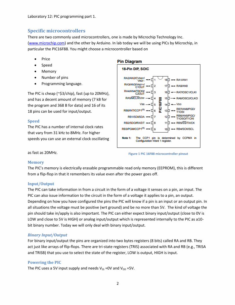
The PIC is cheap (~$3/chip), fast (up to 20MHz),
and has a decent amount of memory (7 kB for
the program and 368 B for data) and 16 of its
18 pins can be used for input/output.
Speed
The PIC has a number of internal clock rates
that vary from 31 kHz to 8MHz. For higher
speeds you can use an external clock oscillating
as fast as 20MHz.
Memory
The PIC’s memory is electrically erasable programmable read only memory (EEPROM), this is different
from a flip-flop in that it remembers its value even after the power goes off.
Input/Output
The PIC can take information in from a circuit in the form of a voltage it senses on a pin, an input. The
PIC can also issue information to the circuit in the form of a voltage it applies to a pin, an output.
Depending on how you have configured the pins the PIC will know if a pin is an input or an output pin. In
all situations the voltage must be positive (wrt ground) and be no more than 5V. The kind of voltage the
pin should take in/apply is also important. The PIC can either expect binary input/output (close to 0V is
LOW and close to 5V is HIGH) or analog input/output which is represented internally to the PIC as a10-
bit binary number. Today we will only deal with binary input/output.
Binary Input/Output
For binary input/output the pins are organized into two bytes registers (8 bits) called RA and RB. They
act just like arrays of flip-flops. There are tri-state registers (TRIS) associated with RA and RB (e.g., TRISA
and TRISB) that you use to select the state of the register, LOW is output, HIGH is input.
Powering the PIC
The PIC uses a 5V input supply and needs VSS =0V and VDD =5V.
Figure 1 PIC 16F88 microcontroller pinout
Laboratory 12: PIC programming part 1.
3
Programming a PIC using MPlab X MPlab X is an integrated development environment, IDE. For our purposes this will mean that it four
things will be unified:
A file manager for keeping track of files that contain the code you write.
A text editor for writing the code in.
A compiler for transforming the code from human readable form to machine readable form.
A programmer for storing the machine readable code in the PIC chip.
Getting Started: Let’s create a new project using a PIC 16F88 programmed using the XC8 compiler. This project will cause
a LED to flash using a 1MHz internal clock to keep time.
1. Logon to the computer using the Electronics account, password student.
2. Open MPlab X from the taskbar at the bottom of the screen.
3. Under File select New Project…
4. In the pop-up window under Projects select Standalone Project and then click Next.
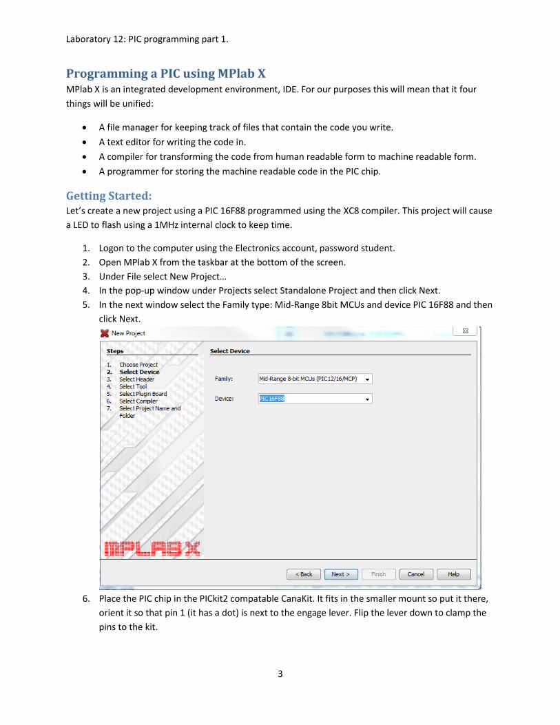
5. In the next window select the Family type: Mid-Range 8bit MCUs and device PIC 16F88 and then
click Next.
6. Place the PIC chip in the PICkit2 compatable CanaKit. It fits in the smaller mount so put it there,
orient it so that pin 1 (it has a dot) is next to the engage lever. Flip the lever down to clamp the
pins to the kit.
Laboratory 12: PIC programming part 1.
4
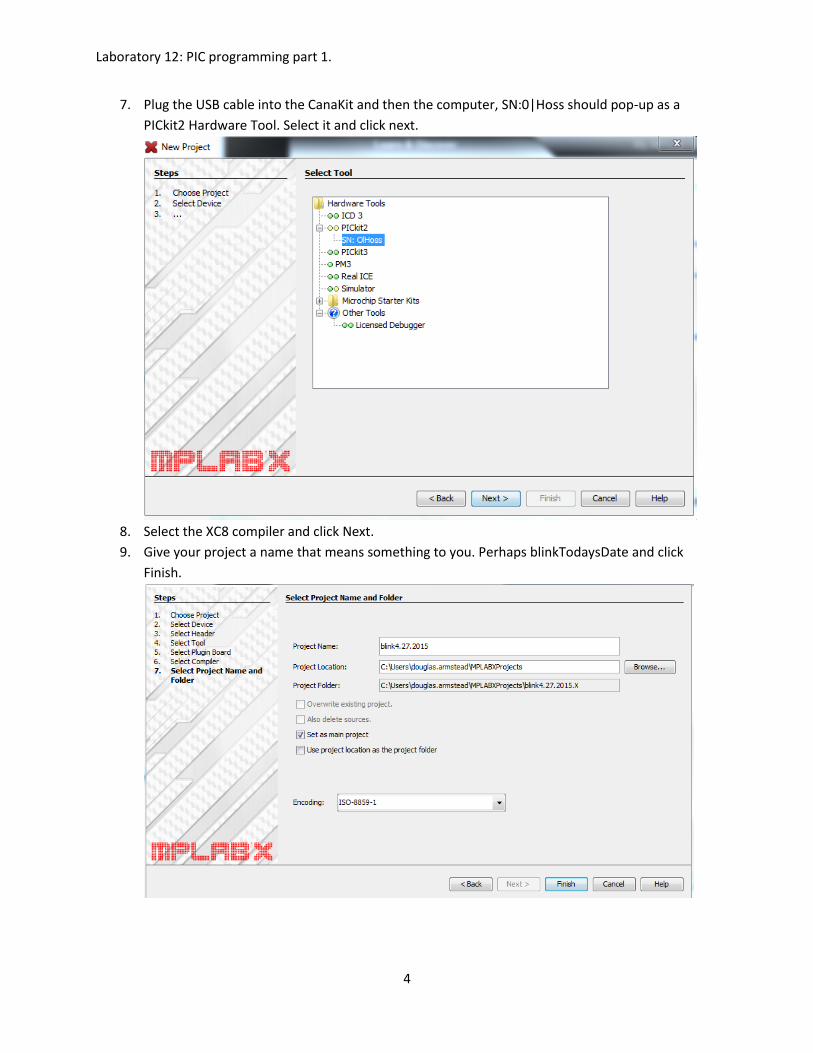
7. Plug the USB cable into the CanaKit and then the computer, SN:0|Hoss should pop-up as a
PICkit2 Hardware Tool. Select it and click next.
8. Select the XC8 compiler and click Next.
9. Give your project a name that means something to you. Perhaps blinkTodaysDate and click
Finish.
Laboratory 12: PIC programming part 1.
5
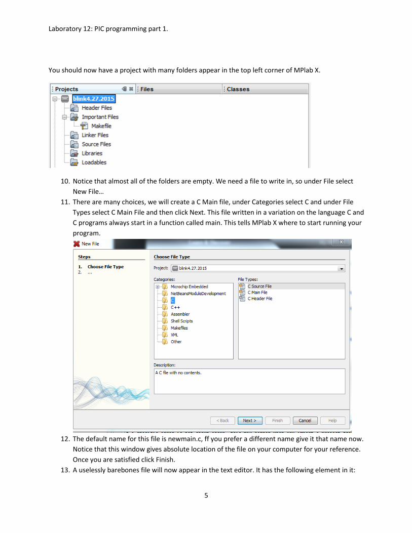
You should now have a project with many folders appear in the top left corner of MPlab X.
10. Notice that almost all of the folders are empty. We need a file to write in, so under File select
New File…
11. There are many choices, we will create a C Main file, under Categories select C and under File
Types select C Main File and then click Next. This file written in a variation on the language C and
C programs always start in a function called main. This tells MPlab X where to start running your
program.
12. The default name for this file is newmain.c, ff you prefer a different name give it that name now.
Notice that this window gives absolute location of the file on your computer for your reference.
Once you are satisfied click Finish.
13. A uselessly barebones file will now appear in the text editor. It has the following element in it:
Laboratory 12: PIC programming part 1.
6
a. Comments (grey and surrounded by the symbols/* */ these are here to clarify the text
to the reader explaining purpose, definitions, logic, etc. that may not be obvious. In this
case it specifies the filename, author, and date the file was originally created.
b. Include files, these are files that explain to the program how to do certain things. The
first included file (stdio.h) explains how to do standard input/output operations such as
printing to the screen and reading from the keyboard. The second explains how to
convert between variable types. The # in front of include tells the C compiler to treat the
include command in a special way (unnecessary detail: the # makes it a pre-processor
command).
c. The main function. It has an integer type and in principle has two arguments (argc and
argv). These have no purpose in this context. The main function is where things start to
happen.
i. The return statement. Each function ends at a return. The return must match
the type of the function, EXIT_SUCCESS is a constant with integer value 0 and is
defined in stdlib.h. (You can see this by right clicking on it, many choices will
appear, selecting Navigate will allow you to Go to Declairation. In a new window
stdlib.h will open up and highlight the line on which EXIT_SUCCESS was define.)
ii. Notice that the return statement has a semicolon at its end. These are used in
place of periods to complete the program equivalent of a sentence. As with any
writing spelling, capitalization, and grammar are important. Lines starting with a
# never end with semicolon.
Basic configuration and setting up the clock. 14. As it stands this program knows exactly zero about the fact that it will be run on a PIC.
a. To start to fix this we specify the clock frequency that we will set the PIC to use, 1MHz:
#define _XTAL_FREQ 1000000
b. Include another file called xc.h. This include file defines how to interact with the PIC:
#include <xc.h>
c. The rest of a basic configuration which is boiler plate (you never have to change it).
// BEGIN CONFIG
#pragma config FOSC = INTOSCIO
// Oscillator Selection bits (selects internal oscillator at 31kHz)
#pragma config WDTE = OFF // Watchdog Timer Enable bit (WDT disabled)
#pragma config PWRTE = OFF // Power-up Timer Enable bit (PWRT disabled)
#pragma config BOREN = ON // Brown-out Reset Enable bit (BOR enabled)
#pragma config LVP = OFF
// Low-Voltage (Single-Supply) In-Circuit Serial Programming
// Enable bit (RB3 is digital I/O, HV on MCLR must be used for programming)
#pragma config CPD = OFF, CP = OFF, WRT = OFF
// Flash Program Memory Code Protection bits
//(Code protection and write protection off)
//END CONFIG
Laboratory 12: PIC programming part 1.
7
d. These configurations can be set by menu using Window -> PIC memory views ->
Configuration Bits. The button Generate Source Code to Output gives you text that can
be cut and pasted into your code.
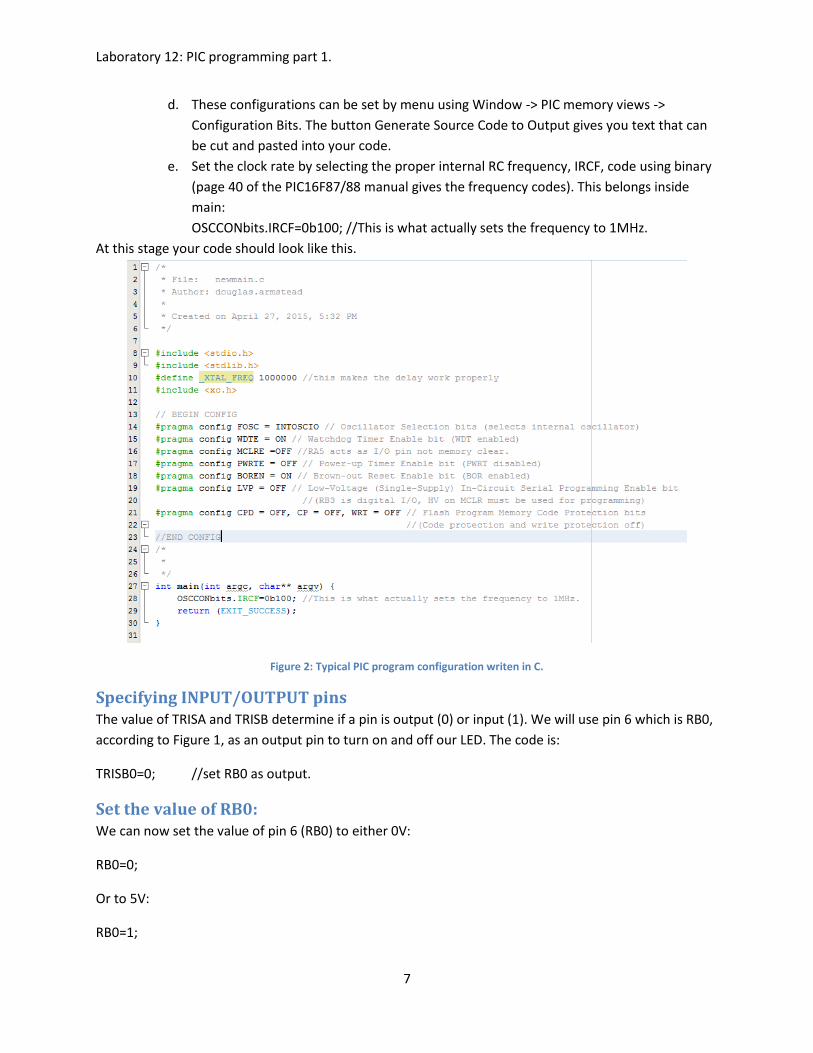
e. Set the clock rate by selecting the proper internal RC frequency, IRCF, code using binary
(page 40 of the PIC16F87/88 manual gives the frequency codes). This belongs inside
main:
OSCCONbits.IRCF=0b100; //This is what actually sets the frequency to 1MHz.
At this stage your code should look like this.
Figure 2: Typical PIC program configuration writen in C.
Specifying INPUT/OUTPUT pins The value of TRISA and TRISB determine if a pin is output (0) or input (1). We will use pin 6 which is RB0,
according to Figure 1, as an output pin to turn on and off our LED. The code is:
TRISB0=0; //set RB0 as output.
Set the value of RB0: We can now set the value of pin 6 (RB0) to either 0V:
RB0=0;
Or to 5V:
RB0=1;
Laboratory 12: PIC programming part 1.
8
Applying one voltage and then immediately the other happens too quickly to see, we need a delay:
__delay_ms(1000); //wait 1000ms, notice the double underscore before delay.
(MPlab X will complain about __delay_ms being undefined, this complaint is a bug in MPlab X).
To do this repetitively we need a loop, an infinite loop will do:
while(1==1){
thing to be repeated.
}
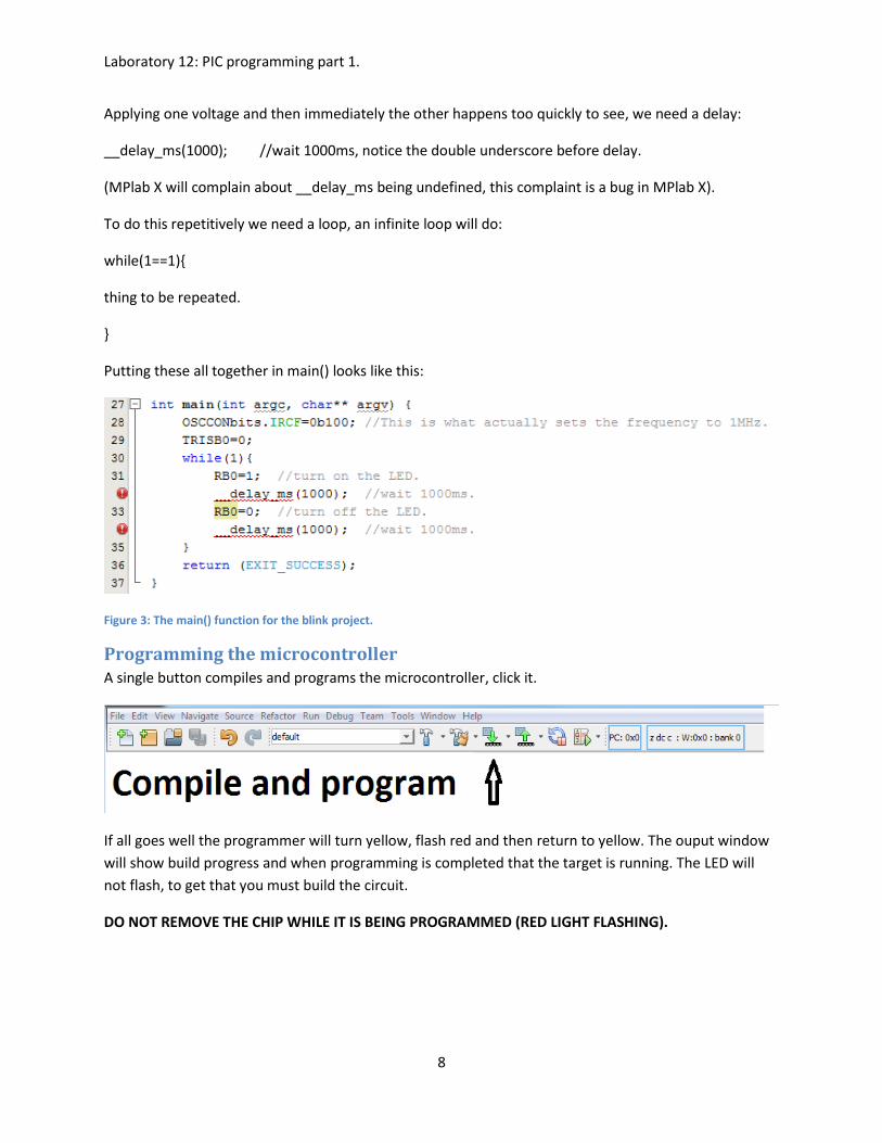
Putting these all together in main() looks like this:
Figure 3: The main() function for the blink project.
Programming the microcontroller A single button compiles and programs the microcontroller, click it.
If all goes well the programmer will turn yellow, flash red and then return to yellow. The ouput window
will show build progress and when programming is completed that the target is running. The LED will
not flash, to get that you must build the circuit.
DO NOT REMOVE THE CHIP WHILE IT IS BEING PROGRAMMED (RED LIGHT FLASHING).
Laboratory 12: PIC programming part 1.
9
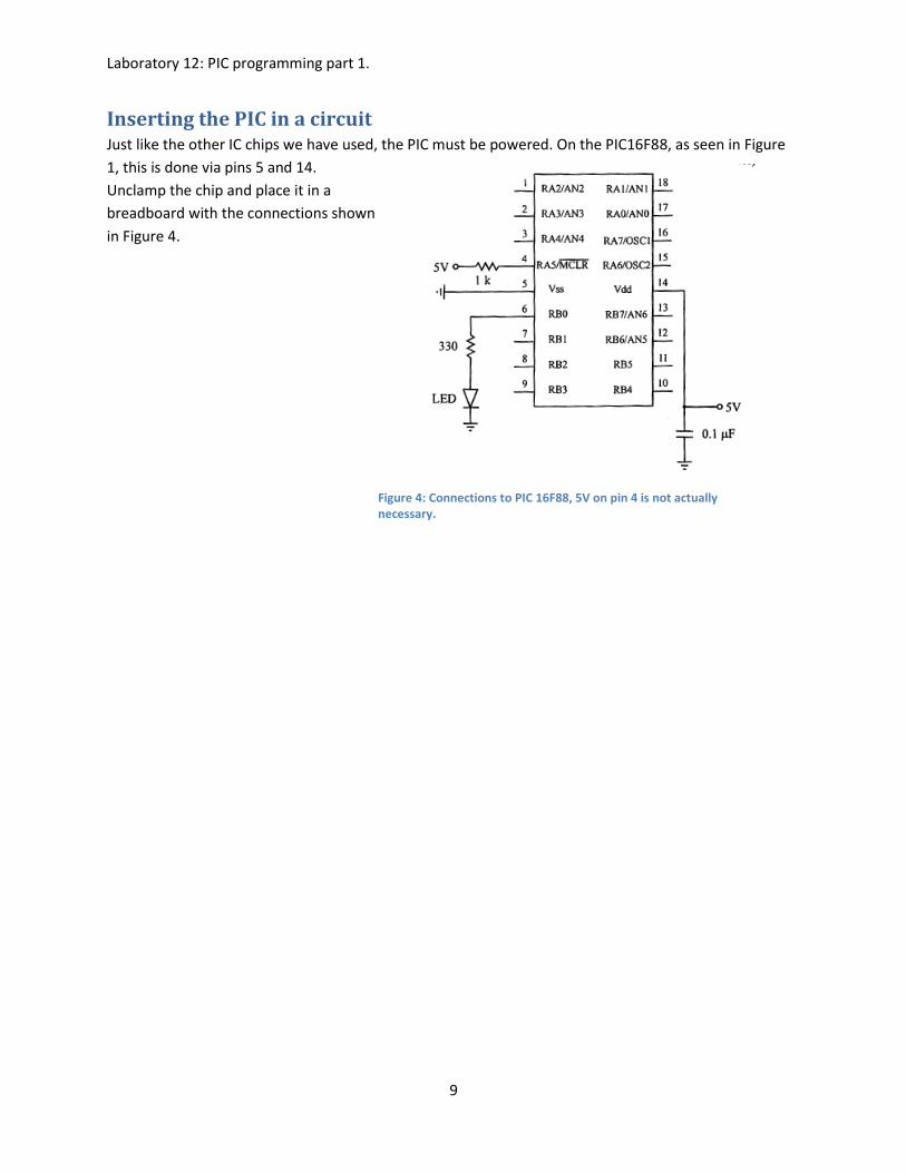
Inserting the PIC in a circuit Just like the other IC chips we have used, the PIC must be powered. On the PIC16F88, as seen in Figure
1, this is done via pins 5 and 14.
Unclamp the chip and place it in a
breadboard with the connections shown
in Figure 4.
Figure 4: Connections to PIC 16F88, 5V on pin 4 is not actually necessary.
Laboratory 12: PIC programming part 1.
10
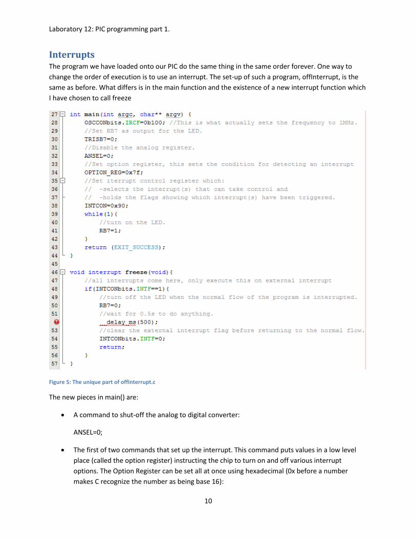
Interrupts The program we have loaded onto our PIC do the same thing in the same order forever. One way to
change the order of execution is to use an interrupt. The set-up of such a program, offInterrupt, is the
same as before. What differs is in the main function and the existence of a new interrupt function which
I have chosen to call freeze
Figure 5: The unique part of offInterrupt.c
The new pieces in main() are:
A command to shut-off the analog to digital converter:
ANSEL=0;
The first of two commands that set up the interrupt. This command puts values in a low level
place (called the option register) instructing the chip to turn on and off various interrupt
options. The Option Register can be set all at once using hexadecimal (0x before a number
makes C recognize the number as being base 16):
Laboratory 12: PIC programming part 1.
11
OPTION_REG=0x7f;
using binary (0b before a number makes C recognize it as being a base 2):
OPTION_REG=0b01111111;
or one bit at a time with the meaning of each bit value given in the comments:
OPTION_REGbits.nRBPU =0; //bit 7 enable RB0 pull-up OPTION_REGbits.INTEDG=1; //bit 6 interrupt on rising edge of RB0/INT pin. OPTION_REGbits.T0CS=1; //bit 5 Transition on RA4/T0CK1 pin OPTION_REGbits.T0SE=1; //bit 4 incr. on high->low transition of RA4/T0CK1 pin OPTION_REGbits.PSA=1; //bit 3 Prescales Watch Dog Timer, WDT OPTION_REGbits.PS = 0b111; //bits 0-2, multiplier of 1:128 used with WDT rate.
The second command to set up the interrupt is to fill a second low level place (called the control
register) that keeps track of which interrupts are allowed and which have been triggered.The
value we will assign to the Interrupt Control Register in hexadecimal is:
INTCON=0x90;
binary:
INTCON=0b10010000;
or bit by bit with the implications of the bit value explained in the comments:
INTCONbits.GIE=1; //bit 7 enable global interrupts INTCONbits.PEIE=0; //bit 6 no peripheral interrupts allowed INTCONbits.TMR0IE=0; //bit 5 no timer interrupts allowed INTCONbits.INTE=1; //bit 4 RB0/INT External interrupt enabled INTCONbits.RBIE=0; //bit 3 no RB port change enabled INTCONbits.TMR0IF=0; //bit 2 timer overflow flag off INTCONbits.INTF=0; //bit 1 external interrupt flag off. INTCONbits.RBIF=0; //bit 0 RB port change flag off.
It is important to note that only Option Register bits 6 & 7 matter for this example and bits 0-5
are irrelevant. The reason being that the external interrupt is the only interrupt enabled in the
Interrupt Control Register. Note also that with INTCON bits 3, 5 and 6 set to zero, bits 0 and 2
become irrelevant.
The program jumps to freeze() if an interrupt occurs. Once there freeze :
checks for an external interrupt
flag flashes the LED off for 0.5s
clears the interrupt flag and then
returns to main().
Laboratory 12: PIC programming part 1.
12
You will attach a normally off switch to RB0 to interrupt the normal flow of the program.
Details about the Option and IntCon registers follow.
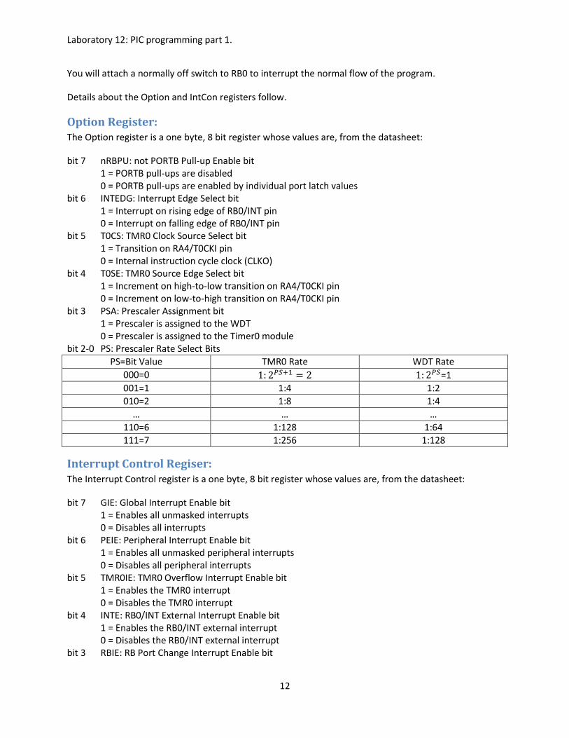
Option Register: The Option register is a one byte, 8 bit register whose values are, from the datasheet:
bit 7 nRBPU: not PORTB Pull-up Enable bit 1 = PORTB pull-ups are disabled 0 = PORTB pull-ups are enabled by individual port latch values
bit 6 INTEDG: Interrupt Edge Select bit 1 = Interrupt on rising edge of RB0/INT pin 0 = Interrupt on falling edge of RB0/INT pin
bit 5 T0CS: TMR0 Clock Source Select bit 1 = Transition on RA4/T0CKI pin 0 = Internal instruction cycle clock (CLKO)
bit 4 T0SE: TMR0 Source Edge Select bit 1 = Increment on high-to-low transition on RA4/T0CKI pin 0 = Increment on low-to-high transition on RA4/T0CKI pin
bit 3 PSA: Prescaler Assignment bit 1 = Prescaler is assigned to the WDT 0 = Prescaler is assigned to the Timer0 module
bit 2-0 PS: Prescaler Rate Select Bits
PS=Bit Value TMR0 Rate WDT Rate
000=0 1: 2𝑃𝑆+1 = 2 1: 2𝑃𝑆=1
001=1 1:4 1:2
010=2 1:8 1:4
… … …
110=6 1:128 1:64
111=7 1:256 1:128
Interrupt Control Regiser: The Interrupt Control register is a one byte, 8 bit register whose values are, from the datasheet:
bit 7 GIE: Global Interrupt Enable bit 1 = Enables all unmasked interrupts 0 = Disables all interrupts
bit 6 PEIE: Peripheral Interrupt Enable bit 1 = Enables all unmasked peripheral interrupts 0 = Disables all peripheral interrupts
bit 5 TMR0IE: TMR0 Overflow Interrupt Enable bit 1 = Enables the TMR0 interrupt 0 = Disables the TMR0 interrupt
bit 4 INTE: RB0/INT External Interrupt Enable bit 1 = Enables the RB0/INT external interrupt 0 = Disables the RB0/INT external interrupt
bit 3 RBIE: RB Port Change Interrupt Enable bit
Laboratory 12: PIC programming part 1.
13
1 = Enables the RB port change interrupt 0 = Disables the RB port change interrupt
bit 2 TMR0IF: TMR0 Overflow Interrupt Flag bit 1 = TMR0 register has overflowed (must be cleared in software) 0 = TMR0 register did not overflow
bit 1 INTF: RB0/INT External Interrupt Flag bit 1 = The RB0/INT external interrupt occurred (must be cleared in software) 0 = The RB0/INT external interrupt did not occur
bit 0 RBIF: RB Port Change Interrupt Flag bit A mismatch condition will continue to set flag bit RBIF. Reading PORTB will end the mismatch condition and allow flag bit RBIF to be cleared. 1 = At least one of the RB7:RB4 pins changed state (must be cleared in software) 0 = None of the RB7:RB4 pins have changed state
More external interrupts are possible on RB4-7 if one chose to activate them.
Procedure: 1. Use MPlabX to create a blink project drawing on Figs. 2 and 3.
2. Program your PIC chip and then install it in your circuit.
3. Alter your program to make the LED flash at a rate of 1Hz.
4. Repeat steps 1&2 for the offInterrupt project. Be sure to create an entirely new project. Before
you construct the circuit for offInterrupt, draw the schematic below being certain to include all
components. Show me your schematic before you build it and convince me that your changes
are appropriate. The program should turn on an LED attached to PortB.7. An interrupt on
PortB.0 should cause the LED to turn off for half a second, and then turn back on again. This
should be signaled by a no button switch. You must make sure to wire the switch so that the ON
state applies 5V DC to the pin, and the OFF state grounds the pin. The input should not be
allowed to “float” in the OFF state. When you are sure you have all components wired properly,
apply power to the circuit and test it for proper function.
Always use a chip-puller to remove your chip from the breadboard so you don’t damage it by
bending or breaking its pins.
Your schematic:
Laboratory 12: PIC programming part 1.
14
LAB 12 QUESTIONS
Names:
1. Explain all differences between PORTA and PORTB if using the pins for inputs. Refer to Section
7.8 in the textbook for more information.
2. For the offInterrupt example, if the button is held down for more that 0.5 second and then
released, is it possible that the LED would blink off again? If so, explain why. (Hint: consider
switch bounce.)
3. Show two different ways to simply and properly interface an LED to a PIC output pin. One circuit
should light the LED only when the pin is high (this is called positive logic) and the other circuit
should light the LED only when the pin is low (this is called negative logic).


![Pic microcontroller [autosaved] [autosaved]](https://img.pdfslide.net/doc/110x75/547c27a4b37959582b8b4f25/pic-microcontroller-autosaved-autosaved.jpg)