Embed Size (px)
Citation preview
DEPARTMENT OF COMMERCEBUREAU OF STANDARDS
S. W. STSATTON, Duticrot
PROGRESS REPORTOF THE
NATIONAL SCREW THREAD COMMISSION
(AUTHORIZED BY CONGRESS, JULY 18, 1918,
H. R. 10852)
AS APPROVED JUNE 19, 1920
JANUARY 4, 1921
MISCELLANEOUS PUBLICATIONSOF THE
BUREAU OF STANDARDS
No. 42
WASHINGTON«OVIRNMENT PRINTING OFFICE

.- -
NATIONAL SCREW THREAD COMMISSION,WASHINGTON,
June ig, 1920.
The accompanying Progress Report of the National Screw
Thread Commission has been approved by the Commission, and
by the Secretaries of War, Navy, and Commerce, in accordance
with the provisions of the law establishing the Commission.
APPROVAL BY THE MEMBERS OF THE COMMISSION.
The Progress Report of the National Screw Thread Commission, as
revised in accordance with the vote of November 23-24, 1919, and
embodying certain changes recommended by a special committee of
the Society of Automotive Engineers, is hereby approved.
S. W. Stratton,
Chairman.
B. C. Peck,
J. O. Johnson,
Representing the United States Army.
N. H. Wright,
P. M. McNair,
Representing the United States Navy.
James Hart'ness,
F. O. Wells,
Nominated by the American Society of Mechanical Engineers.
E. H. Ehrman,H. T. Herr,
Nominated by the Society of Automotive Engineers.
approval by the secretaries of war, navy, and commerce.
The attached report prepared by the National Screw Thread Com-mission, in accordance with the law establishing the Commission (Public
doc. No. 201, 65th Cong., H. R. 10852), is hereby accepted and approved.
Newton D. Baker,
Secretary of War.
Josephus Daniels,
Secretary of the Navy.
Joshua W. Alexander,
Secretary of Commerce.35455°—21
WASHINGTON : GOVERNMENT PRINTING OFFICE : 1921

DEPARTMENT OF COMMERCEBUREAU OF STANDARDS
S. W. STRATTON, Director
PROGRESS REPORTOF THE
NATIONAL SCREW THREAD COMMISSION
(AUTHORIZED BY CONGRESS, JULY 18, 1918,
H. R. 10852)
AS APPROVED JUNE 19, 1920
JANUARY 4, 1921
MISCELLANEOUS PUBLICATIONSOF THE
BUREAU OF STANDARDS
No. 42
WASHINGTONGOVERNMENT PRINTING OFFICE
1921
PREFACE
Recognizing the impossibility of bringing out a report of this
character which in the first issue in entirely free from error or
inconsistency, Congress has extended the life of the commission
for a period of two years, in which such corrections and changes
will be made as are found necessary or desirable by practical use of
the report in the designing room and in the shop.
Criticisms and suggestions for the improvement of the report
should be addressed to the National Screw Thread Commission,
Bureau of Standards, Washington, D. C.
2
PROGRESS REPORT OF THE NATIONAL SCREWTHREAD COMMISSION
(Authorized by Congress, July 18, 1918, H. R. 10852)
AS APPROVED JUNE 19, 1920
CONTENTS Page
Preface 2
I. Introduction 4
1 . Origin and progress of commission 4
2. Purpose of report , . 4
3. Utility of report 5
4. Organization and procedure of commission 5
5. Arrangement of report 5
II. Terminology 6
1. Introductory 6
2. Definitions 6
3. Symbols 8
4. Illustrations showing terminology 9
III. Form of thread 9
r. National form 9
2. National fire-hose coupling-thread form 13
3. National hose-coupling thread form 16
IV. Thread series adopted 16
1. Introductory : 16
2. National coarse-thread series 17
3. National fine-thread series 17
4. National fire-hose coupling threads 18
5. National hose-coupling threads 18
6. National pipe-thread series 19
V. Classification and tolerances 21
1. General L 21
2. Classification of fits 22
(a) General specifications 23
(b) Class I, loose fit 23
(c) Class II-A, medium fit (regular) 33
(d) Class II-B, medium fit (special) 41
(e) Class III, close fit -. 47
(/) Class IV, wrench fit 55
3. Tolerances 56
(a) Tolerances represent extreme variations 56
(6) Pitch diameter tolerances 56
(c) Class I and Class II tolerances. . v 56
(d) Pitch diameter tolerances on screw 56
(e) Tolerances on major diameter of screw 56
(J) Tolerances on minor diameter of screw 56
(g) Tolerances on major diameter of nut 57
(h) Tolerances on minor diameter of nut 57
(i) Illustration 57
(_/') Scope of tolerance specifications 57
3
4 NATIONAL SCREW THREAD COMMISSION
Page
VI. Gages S8
i. Introductory 58
(a) Fundamentals 58
(b) Gage classification 60
VII. National pipe threads 60
1. Introductory 60
2 . National standard pipe threads 61
VIII. Future work of commission 84
Threads requiring standardization 84
2. Standardization of products closely allied to the manufacture of
screw threads 84
3. Possibility of international standardization 84
IX. Appendixes 86
1. Origin of the commission 86
2. Organization of the commission 87
3. Procedure of commission 89
4. Historical 93
5. Technical 94
6. Gages and methods of test 98
7. Typical specifications for screw-thread products 107
X. Index 109
I. INTRODUCTION1. ORIGIN AND PROGRESS OF COMMISSION
The National Screw Thread Commission, which was created byan act of Congress (H. R. 10852) approved July 18, 191 8, for the
purpose ofv ascertaining and establishing standards for screw
threads for use of the various branches of the Federal Govern-
ment and for the use of manufacturers, recommends herewith
certain systems of threads, together with information, data, and
specifications pertaining to the manufacture of the threads recom-
mended.2. PURPOSE OF REPORT
It is the desire of the commission to make available to Amer-
ican manufacturers at the present time the information contained
in its progress report for immediate use, rather than delay making
a report in order to consider more fully the possibilities of inter-
national standardization of screw threads. It is the opinion of
the commission, however, that international standardization of
screw threads is very desirable and that the present time is mostopportune for accomplishments in this direction. Further refer-
ence is made to the possibilities of international standardization
in Section VIII of this report.
In the time provided in the act of Congress the commission
has devoted its attention to the standardization of only those
threads, sizes, types, and systems which are of paramount im-
portance by reason of their extensive use and utility. As indi-
PROGRESS REPORT 5
cated in Section VIII, there remains much to be accomplished
along the lines of standardization of special but important threads,
and of maintaining progress in our standardization work in keep-
ing with the developments of manufacturing conditions.
3. UTILITY OF REPORT
The advances made by the commission up to date will reduce
the variety of screw threads in general use, facilitate manufacture
in case of war, make the best use of labor in our industries in time
of peace, increase the safety of travel by rail, steamship, andaeroplane, and in general will increase the dependability of all
mechanisms. The war has given a new life to industrial activities
in all countries and has made it necessary for us not only to share
in the progress in standardization but to take advantage of every
possible means to maintain America's progress. We, as a people,
are keenly awake to the economic necessities of the reconstruction
period and the period of peace following, and every step toward
standardization of our products will result in increased production
with a minimum expenditure of materials, energies, and other
resources.
4. ORGANIZATION AND PROCEDURE OF COMMISSION
Prior to the formal appointment, under date of September 21,
1 918, of the various commissioners, a preliminary meeting washeld at "Washington, D. C, on September 12. At this preliminary
meeting was outlined the detailed organization of the commission
as described in Appendix 2 and, also, a program covering the pro-
cedure of the commission as described in Appendix 3.
The commission in formulating this progress report has acted
largely in the capacity of a judiciary, basing its decisions upon
evidence received from authorities on screw-thread subjects and
upon the conclusions drawn by other organizations having to do
with standardization of screw threads. In addition, the various
subjects dealt with have been considered with a knowledge of
present manufacturing conditions and with anticipation of further
development in the production of screw-thread products. Aboveall, it is the intention of the commission to facilitate and promote
progress in manufacture.
5. ARRANGEMENT OF REPORT
There are included in the body of the report matters of partic-
ular importance and of general interest, while in the appendixes
there is arranged detailed information of both a general and a
technical nature. There is included in the body of the report
6 NATIONAL SCREW THREAD COMMISSION
sufficient information to permit the writing of definite and com-
plete specifications for the purchase of screw-thread products,
and there is included in the appendixes material which explains
or goes more fully into the application of the specifications. Thesubjects covered in the report are arranged in the following
manner
:
I. Introductory.
II. Terminology.
III. Form of thread.
IV. Thread series adopted.
V. Classification and tolerances.
VI. Gages.
VII. National pipe threads.
VIII. Future work of commission.
IX. Appendixes.
X. Index.
II. TERMINOLOGY1. INTRODUCTORY
In this progress report there are utilized, as far as possible,
nontechnical words and terms which would best convey to the
producer and user of screw threads the information presented.
2. DEFINITIONS
The following definitions are given of the more important
terms used in the report. Definitions of terms which are obvi-
ously elementary in character are intentionally omitted.
(a) Words Relating to Screw Threads.— i . Screw Thread.—A ridge of uniform section wound in the form of a helix on the
inside or outside surface of a cylinder or cone.
2. Screw Helix.—The path of a point moving at a uniform
angular rate on a cylindrical or conical surface and at the same
time moving at a uniform axial rate.
3. Major Diameter {formerly known as "outside diameter")
.
—The largest diameter of the thread on the screw or nut. The term
"major diameter" replaces the term "outside diameter" as ap-
plied to the thread of a screw and also the term "full diameter"
as applied to the thread of a nut.
4. Minor Diameter (formerly known as "core diameter").—The
smallest diameter of the thread on the screw or nut. The term
"minor diameter" replaces the term "core diameter" as applied
to the thread of a screw and also the term "inside diameter" as
applied to the thread of a nut.
5. Pitch Diameter.—On a straight screw thread the diameter of
an imaginary cylinder which would pass through the threads at
PROGRESS REPORT 7
such points as to make the width of the threads and the width
of the spaces cut by the surface of the cylinder equal
6. Pitch.—The distance from a point on a screw thread to a
corresponding point on the next thread measured parallel to the
axis.
p Number of threads per inch.
7. Lead.—The distance a screw thread advances axially in one
turn. On a single-thread screw, the lead and pitch are identical;
on a double-thread screw, the lead is twice the pitch; on a triple-
thread screw, the lead is three times the pitch, etc.
8. Angle of Thread.—The angle included between the sides of
the thread measured in an axial plane.
9. Helix Angle.—The angle made by the helix of the thread at
the pitch diameter with a plane perpendicular to the axis.
10. Crest.—The top surface joining the two sides of a thread.
11. Root.—The bottom surface joining the sides of two adja-
cent threads.
12. Side.—The surface of the thread which connects the crest
with the root.
13. Axis of a Screw.—The longitudinal central line through the
screw.
14. Base of Thread.—The bottom section of the thread, the
greatest section between the two adjacent roots.
15. Depth of Thread.—The distance between the top and the
base of thread measured normal to the axis.
16. Number of Threads.—Number of threads in any unit of
length.
17. Length of Engagement.—The length of contact between
two mating parts, measured axially.
18. Depth of Engagement.—The depth of thread in contact of
two mating parts, measured radially.
(6) Words Relating to Classification and Tolerances.—1. Allowance {Neutral Zone).—A difference in dimensions, the
limits of which are prescribed; it is to provide for different kinds
or classes of fit.
2. Tolerance.—A definite difference in the dimensions pre-
scribed in order to permit of variations in manufacture.
Extreme Tolerance.—The maximum and minimum tolerance
permitted by the designer, the limits of which are to be placed
on the drawings. It is the net tolerance as affected by the
master-gage tolerance.
8 NATIONAL SCREW THREAD COMMISSION
Net Tolerance.—The tolerance limits within which the product
is ordinarily passed by the master gages. It is the extreme
tolerance as affected by the master-gage increment.
j. Basic.—The theoretical or nominal standard size from which
all variations are made.
4. Finish.—The character of the surface on a screw thread.
5. Crest Clearance.—Defined on a screw form as the space
between the top of a thread and the root of its mating thread.
6. Fit.—The relation between two mating parts with reference
to ease of assembly; for example: Wrench fit; close fit; mediumfit; loose fit. The quality of fit is dependent upon both the
relative size and the quality of finish of the mating parts.
7. Neutral Zone {Allowance).—A space between the mating
parts which must not be encroached upon.
8. Gage Increment.—Gage increment is a predetermined allow-
ance by which the net tolerance of the product is increased for
gaging purposes.
9. Limits.—The extreme dimensions, which are prescribed, to
provide for variations in fit and workmanship.
3. SYMBOLS
For use in formulas for expressing relations of screw threads
and for use on drawings and for similar purposes the following
symbols should be used:
Major diameter D(Corresponding radius) d
Pitch diameter E(Corresponding radius) e
Minor diameter K(Corresponding radius) k
Angle of thread A(One-half angle of thread) a
Number of turns per inch NNumber of threads per inch n
Lead P =jr
Pitch or thread interval b =—^ nHelix angle s
pTangent of helix angle S =3.14159X.E
Width of basic flat at top, crest, or root FDepth of basic truncation /Depth of sharp V-thread HDepth of national (U. S.) form of thread h
Included angle of taper Y(One-half included angle of taper) y
Additional Symbols for national pipe threads are given in Sec. VII.
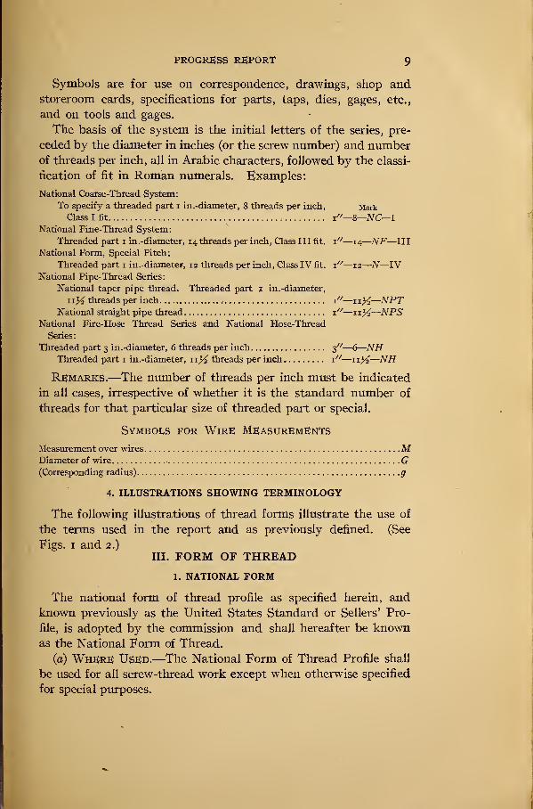
PROGRESS REPORT 9
Symbols are for use on correspondence, drawings, shop andstoreroom cards, specifications for parts, taps, dies, gages, etc.,
and on tools and gages.
The basis of the system is the initial letters of the series, pre-
ceded by the diameter in inches (or the screw number) and numberof threads per inch, all in Arabic characters, followed by the classi-
fication of fit in Roman numerals. Examples:
National Coarse-Thread System:
To specify a threaded part i in.-diameter, 8 threads per inch, Mark
Class I fit x"—8
—
NC—
I
National Fine-Thread System:
Threaded part i in.-diameter, 14 threads per inch, Class III fit. x"—14
—
NF—III
National Form, Special Pitch:
Threaded part 1 in.-diameter, 12 threads per inch, Class IV fit. x"—12
—
N—IVNational Pipe-Thread Series:
National taper pipe thread. Threaded part 1 in.-diameter,
1x% threads per inch 1"—1i^—NPTNational straight pipe thread x"—xx%—NPS
National Fire-Hose Thread Series and National Hose-Thread
Series:
Threaded part 3 in.-diameter, 6 threads per inch 3"—6
—
NHThreaded part 1 in.-diameter, 11% threads per inch x"—
—
NH
Remarks.—The number of threads per inch must be indicated
in all cases, irrespective of whether it is the standard number of
threads for that particular size of threaded part or special.
Symbols for Wire Measurements
Measurement over wires
Diameter of wire
(Corresponding radius).
.
1. NATIONAL FORM
MG9
4. illustrations showing terminology
The following illustrations of thread forms illustrate the use of
the terms used in the report and as previously defined. (See
Figs. 1 and 2.)
III. FORM OF THREAD
The national form of thread profile as specified herein, and
known previously as the United States Standard or Sellers' Pro-
file, is adopted by the commission and shall hereafter be knownas the National Form of Thread.
(a) Where Used.—The National Form of Thread Profile shall
be used for all screw-thread work except when otherwise specified
for special purposes.
IO NATIONAL SCREW THREAD COMMISSION
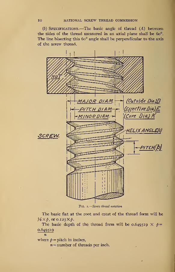
(b) Specifications.—The basic angle of thread (A) between
the sides of the tliread measured in an axial plane shall be 6o°.
The line bisecting this 6o° angle shall be perpendicular to the axis
of the screw thread.
-MAJOR DJAM.
-PJTCH D/ftfyir
SCREW.
(Outside Dia.]B
\(EffectiveDia)E(Core DicQK
HELIXANGLEftJ
-PITCH
i
Fig. i.—Screw thread notation
The basic flat at the root and crest of the thread form will be
yi Xp, or 0.125X/).
The basic depth of the thread form will be 0.649519 X p =
0649519n
where p = pitch in inches,
n = number of threads per inch.
PROGRESS REPORT II
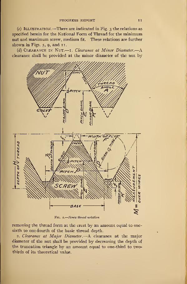
(c) Illustration.—There are indicated in Fig. 3 the relations as
specified herein for the National Form of Thread for the minimumnut and maximum screw, medium fit. These relations are further
shown in Figs. 5, 9, and 11.
(d) Clearance in Nut.— 1. Clearance at Minor Diameter.—
A
clearance shall be provided at the minor diameter of the nut by
Fig. 2.
—
Screw thread notation
removing the thread form at the crest by an amount equal to one-
sixth to one-fourth of the basic thread depth.
2. Clearance at Major Diameter.—A clearance at the major
diameter of the nut shall be provided by decreasing the depth of
the truncation triangle by an amount equal to one-third to two-
thirds of its theoretical value.
12 NATIONAL, SCREW THREAD COMMISSION
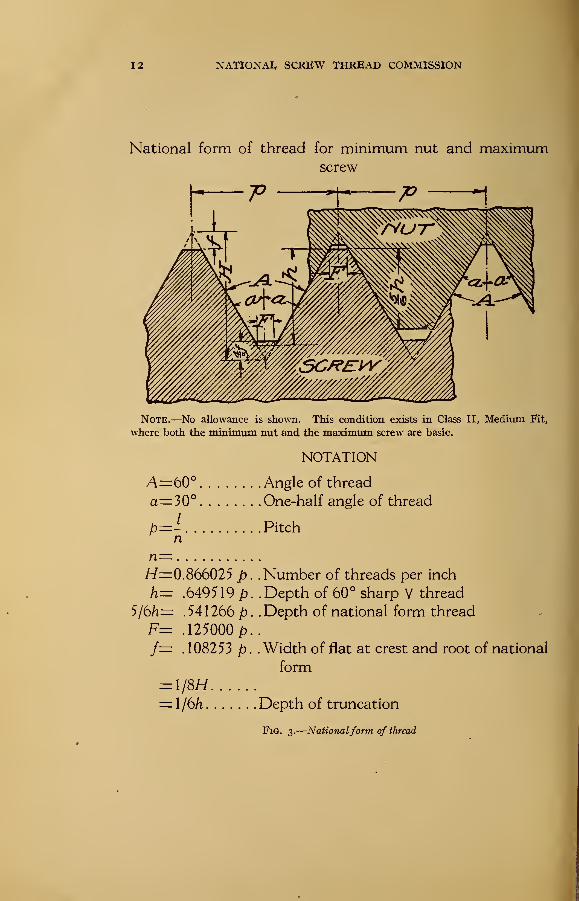
National form of thread for minimum nut and maximumscrew
Note.—No allowance is shown. This condition exists in Class II, Medium Fit,
where both the minimum nut and the maximum screw are basic.
NOTATION
A=bO° Angle of thread
a=30° One-half angle of thread
p=- Pitchn
n=H=0.866025 ph- .649519 p
5/6/i= .541266/?
F= .125000 pf= .108253 p
= l/8H= l/6/i
Fig. 3.
—
Nationalform of thread
. . Number of threads per inch
. .Depth of 60° sharp V thread
. . Depth of national form thread
. . Width of flat at crest and root of national
form
Depth of truncation
PROGRESS REPORT 13
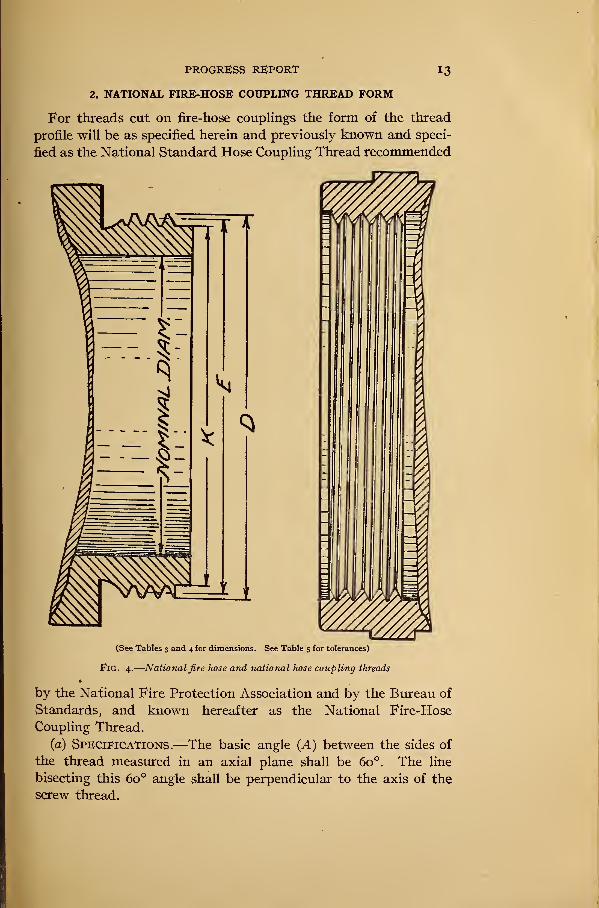
2. NATIONAL FIRE-HOSE COUPLING THREAD FORM
For threads cut on fire-hose couplings the form of the thread
profile will be as specified herein and previously known and speci-
fied as the National Standard Hose Coupling Thread recommended
(See Tables 3 and 4 for dimensions. See Table 5 for tolerances)
Fig. 4.
—
National fire hose and national hose coupling threads
by the National Fire Protection Association and by the Bureau of
Standards, and known hereafter as the National Fire-Hose
Coupling Thread.
(a) Specifications.—The basic angle (A) between the sides of
the thread measured in an axial plane shall be 6o°. The line
bisecting this 6o° angle shall be perpendicular to the axis of the
screw thread.
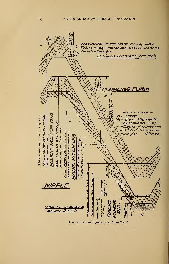
NATIONAL SCREW THREAD COMMISSION
Allc>*rc>r>cGsiand <Z>Jear<ar>ces
Of
7s threads per Inch
BASIC ^/ZSsS
Fig. 5.
—
National fire hose coupling thread
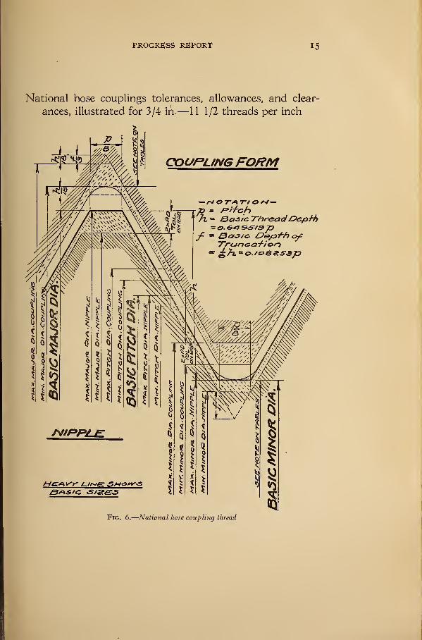
PROGRESS REPORT 15
National hose couplings tolerances, allowances, and clear-
ances, illustrated for 3/4 in.— 11 1/2 threads per inch
COUFUNGFORM
— /V O T*\ TV O /V—p = ri+chh = Basic. 7~hr&adDepth
= o. e,** &&/9pf = Sa&tc. Oe/o^h ofyraneicrf-ior-i
Fig. 6.
—
National hose coupling thread
i6 NATIONAL SCREW THREAD COMMISSION
The crest and root of the basic thread form will be flattened or
truncated from a sharp V-form as follows:
Threads per inch. '. Depth of truncation in inches
4 o. 02
6 01
7K 01
3. NATIONAL HOSE-COUPLING THREAD FORM
For threads cut on hose couplings from |^ inch to 2 inches, inclu-
sive, the National Form of Thread shall be used as specified under
Section III, "Form of Thread."
IV. THREAD SERIES ADOPTED
1. INTRODUCTORY
It is the aim of the commission, in establishing thread systems
for adoption and general use, to eliminate all unnecessary sizes
and in addition to utilize as far as possible present predominating
sizes. While from certain standpoints it would have been de-
sirable to make simplifications in the thread systems and to estab-
lish more thoroughly consistent standards, it is believed that anyradical change at the present time would be out of place and inter-
fere with manufacturing conditions, and would involve great
economic loss.
The testimony given at the various hearings held by the commis-
sion is very consistent in favoring the maintenance of the present
coarse-thread and fine-thread series, the coarse-thread series being
the present "United States Standard" threads, supplemented in
the sizes below one-fourth inch by the standard established by the
American Society of Mechanical Engineers (A. S. M. E.). Thefine-thread series is composed chiefly of standards that have been
found necessary and consists of sizes taken from the standards of
the Society of Automotive Engineers (S. A. E.) , and the fine-thread
series of the American Society of Mechanical Engineers (A. S. M. E.)
The recommendation of these standards will tend toward their
more universal use, and will constitute important gain that is
affected by standardization with a minimum handicap.
Also, the testimony was very consistent in favoring the adop-
tion in practically its present shape of the American Briggs
standard pipe-thread sizes as recommended by the American
Society of Mechanical Engineers and the fire-hose coupling sizes as
established by the National Fire Protection Association.
PROGRESS REPORT 17
2. NATIONAL COARSE-THREAD SERIES
There is specified in Table 1 a thread series which will be knownas the National Coarse-Thread Series. This series contains certain
sizes known previously as the United States Standard threads
and also certain sizes known as the A. S. M. E. machine-screw
threads. There are included in the National Coarse-Thread
Series only those sizes which are essential.
(a) WHERE Used.—The National Coarse Threads are recom-
mended for general use in engineering work, in machine construc-
tion where conditions are favorable to the use of bolts, screws,
and other threaded components where quick and easy assembly
of the parts is desired, and for all work where conditions do not
require the use of fine-pitch threads.
(&) Specifications.—The series of sizes and basic dimensions
are specified in Table 1
.
1 . Form of Thread.—The standard form of thread profile shall be
used as specified and described in Section III, "Form of Thread."
2. Classification and Tolerances.—The National Coarse Thread
shall be manufactured in accordance with the specifications as
given in Section V, "Classification and Tolerances."
3. Gages.—The gages used for the manufacture of National
Coarse Threads will be as specified in Section VI, "Gages."
3. NATIONAL FINE-THREAD SERIES
The threads specified in Table 2 will be known as the National
Fine-Thread Series. This series contains certain sizes knownpreviously as the S. A. E. threads, and, also, certain sizes knownas the A. S. M. E. machine-screw sizes. There are included in the
National Fine-Thread Series, only the sizes which are essential.
(a) Where Used.—The National Fine Threads are recommended
for general use in automotive and aircraft work, for use where
the design requires both strength and reduction in weight, andwhere special conditions require a fine thread, such as, for instance,
on large sizes where sufficient force can not be secured to set
properly a screw or bolt of coarse pitch, by exerting on an ordinary
wrench the strength of a man.
(b) Specifications.—The series of sizes and basic dimensions
are specified in Table 2.
j. Form of Thread.—The standard form of thread profile shall
be used as specified and described in Section III, "Form of
Thread."
12071°—21 2
1 8 NATIONAL SCREW THREAD COMMISSION
2. Classification and Tolerances.—The National Fine Thread
shall be manufactured in accordance with specifications given in
Section V, "Classification and Tolerances."
3. Gages.—The gages used for the manufacture of National
Fine Threads will be as specified in Section VI, "Gages."
4. NATIONAL FIRE-HOSE COUPLING THREADS
There is specified in Table 3 a thread series and basic dimensions
for fire-hose couplings from 2}4 to \Y2 in. diameter which will
be known as the National Fire-Hose Threads. These basic sizes
and dimensions correspond in all details to those recommendedby the National Fire Protection Association and by the Bureau
of Standards.
(a) Where Used.—The National Hose Thread shall be used on
all couplings and hydrant connections for fire-protection systems
and for all other purposes where hose couplings and connections
are required in sizes between 23^ and 4^ in. in diameter.
(b) Specifications.—Series of sizes and basic dimensions for
National Fire-Hose Threads are specified in Table 3.
1. Form of Thread.—There should be used a special form of
thread as specified for National Fire-Hose Threads in Section III,
"Form of Thread."
2. Classification and Tolerances.—National Fire-Hose Threads
shall be manufactured in accordance with the specifications as
given in Section V, "Classification and Tolerances."
3. Gages.—The gages used for the manufacture of National
Fire-Hose Threads will be as specified in Section VI, "Gages."
5. NATIONAL HOSE-COUPLING THREADS
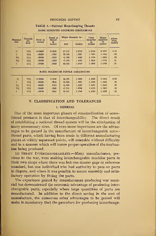
There is specified in Table 4 a thread series and basic dimen-
sions for hose-coupling threads from ^ to 2 in. in diameter,
which will be known as the National Hose-Coupling Threads.
(a) Where Used.—The National Hose-Coupling Thread shall
be used on all couplings and connections where sizes between
and 2 in. in diameter are required.
(b) Specifications.—The series of sizes and basic dimensions
for National Hose-Coupling Threads are specified in Table 4.
1. Form of Thread.—The National Form of Thread as specified
in Section III, "Form of Thread," should be used.
2. Classification and Tolerances.—The National Hose-Coupling
Thread shall be manufactured in accordance with the specifications
as given in Section V, "Classification and Tolerances."
PROGRESS REPORT 19
3. Gages.—The gages used for the manufacture of the National
Hose-Coupling Thread will be as specified in Section VI, "Gages."
• 6. NATIONAL PIPE-THREAD SERIES
There are specified in Section VII, Tables 19, 20, and 21, thread
series and basic dimensions for National Taper Pipe Threads,
National Straight Pipe Threads, and National Locknut Threads.
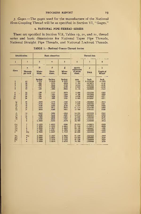
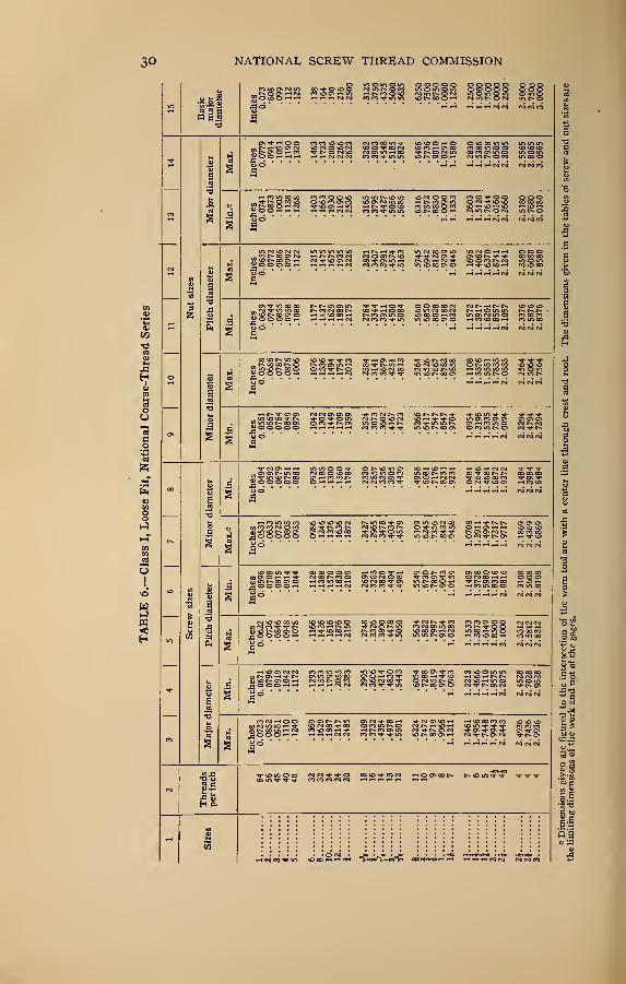
TABLE 1.—National Coarse-Thread Series
Identification Basic diameters Thread data
1 2 3 4 5 6 7 8
n D E K Metric p h
Sizesequivalent
Threads Major Pitch Minor of majorPitch
Depth ot
per inch
-
diam. diam. diam. diam. thread
T U lliLii d b Inch Inch64 073 0629 0527 1 854 n n 1 c-fi?^U. Ul OO-OU 0101
2 56 .086 .0744 .0628 2.' 184 . 0178571 .01163 48 .099 .0855 .0719 2.515 . 0208333 .01354 40 .112 .0958 .0795 2.845 .0250000 .01625 40 .125 .1088 .0925 3.175 .0250000 .0162
6 32 .138 .1177 .0974 3.505 . 0312500 .02038 32 .164 .1437 .1234 4.166 . 0312500 .0203
10 24 .190 .1629 .1359 4.826 .0416667 .0271
12 24 .216 .1889 .1619 5.486 .0416667 .0271
M 20 .2500 .2175 .1850 6.350 . 0500000 .0325
•fV 18 .3125 .2764 .2403 7.938 .0555556 .0361
Vs 16 .3750 .3344 .2938 9.525 .0625000 .0406
A 14 .4375 .3911 .3447 11.113 .0714286 .0464
V* 13 .5000 .4500 .4001 12.700 .0769231 .0500
h 12 .5625 .5084 .4542 14. 288 .0833333 .0541
% 11 .6250 .5660 .5069 15. 875 . 0909091 .0590
% 10 .7500 .6850 .6201 19. 050 . 1000000 .06509 .8750 .8028 .7307 22. 225 .1111111 .0722
1 8 1.0000 .9188 .8376 25.400 . 1250000 .0812
7 1.1250 1.0322 .9394 28. 575 . 1428571 .09287 1 2500 1.1572 1.0644 31.750 . 1428571 .09286 1.5000 1.3917 1.2835 38. 100 . 1666667 .10835 1.7500 1.6201 1.4902 44.450 . 2000000 .1299
2 4^ 2.0000 1.8557 1.7113 50. 800 .2222222 .1443
2H 4^ 2. 2500 2. 1057 1.9613 57. 150 .2222222 .1443
2V2 4 2. 5000 2.3376 2. 1752 63.500 .2500000 .1624
2M 4 2.7500 2.5876 2.4252 69.850 .2500000 .16243 4 3.0000 2.8376 2.6752 76. 200 .2500000 .1624
20 NATIONAL SCREW THREAD COMMISSION
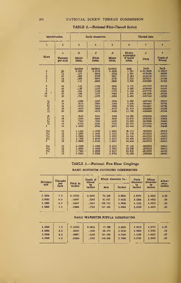
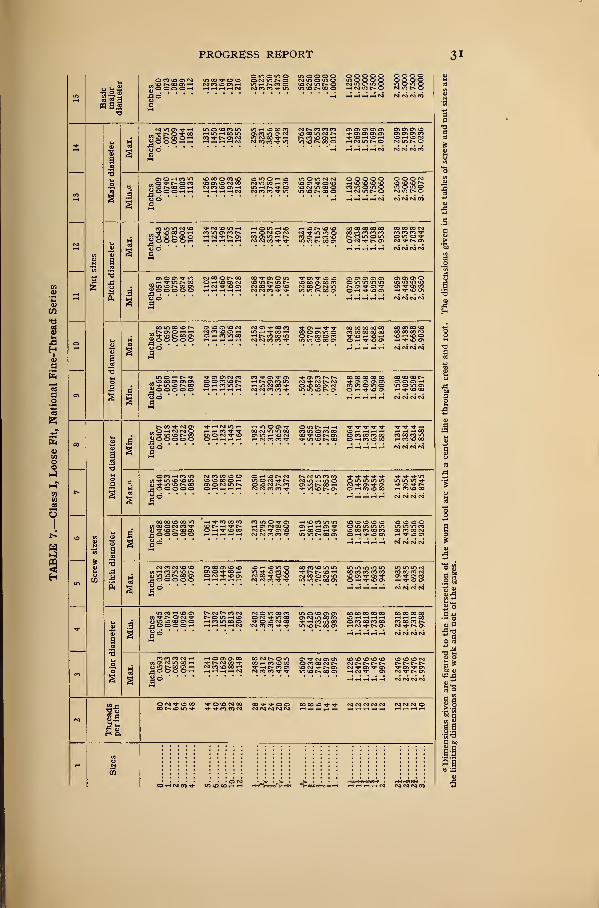
TABLE 2.—National Fine-Thread Series
Identification Basic diameters Thread data
1 2 3 4 5 6 7 8
n D E E Metric V ?!
Sizesequivalent
Threads Major Pitch Minor of majorPitch
jjeptn ot
per inch diam. diam. diam. diam. thread
Tn rTi PC Incti 6 S Inches mm Inch Inch
1° 0.060 0.0519 0. 0438 1.524 0.0125000 0.008121 V2 .073 .0640 .0550 1.854 .0138889 . 009022" 64 . 086 . 0759 . 0657 2. 184 . 0156250 .010143 56 . 099 . 0874 . 0758 2. 515 . 0178571 . 011604 48 . 112 . 0985 . 0849 2.845 . 0208333 . 01353
5 44 .125 .1102 .0955 3.175 .0227273 .014766 40 .138 .1218 .1055 3. 506 .0250000 .016248 36 . 164 . 1460 . 1279 4. 166 . 0277778 . 01804
10"
32 . 190 . 1697 . 1494 4. 826 .0312500 . 0203012 28 . 216 . 1928 . 1696 5. 486 . 0357143 . 02319
M 28 .2500 .2268 .2036 6.350 . 0357143 . 02319
A 24 .3125 .2854 .2584 7.938 . 0416667 . 0270624 . 3750 . 3479 . 3209 9. 525 . 0416667 . 02706
£ 20 . 4375 . 4050 . 3725 11. 113 . 0500000 . 03248
72 20 . 5000 . 4675 . 4350 12. 700 . 03248
18 .5625 .5264 .4903 14.288 .0555556 .0360813 .6250 .5889 .5528 15.875 .0555556 . 03608
& 16 .7500 .7094 .6688 19. 050 .0625000 .04060
% 14 .8750 .8286 .7822 22.225 .0714286 . 04640l 14 1.0000 .9536 .9072 25.400 .0714286 . 04640
12 1.1250 1.0709 1.0167 28. 575 . 0833333 . 0541312 1.2500 1.1959 1.1417 31.750 .0833333 .0541312 1.5000 1.4459 1.3917 38. 100 .0833333 . 05413
1M 12 1.7500 1.6959 1.6417 44.450 .0833333 . 0541312 2.0000 1.9459 1.8917 50. 800 .0833333 .05413
2}4 12 2. 2500 2.1959 2.1417 57.150 . 0833333 .0541312 2.5000 2.4459 2.3917 63. 500 . 0833333 . 05413
2% 12 2.7500 - 2.6959 2.6417 69. 850 . 0833333 .054133 10 3. 0000 2.9350 2.8701 76. 200 . 1000000 . 06495
TABLE 3.—National Fire-Hose Couplings
BASIC MINIMUM COUPLING DIMENSIONS
Nominalsize
Threadsperinch
Pitch ininches
Depth of
threadin
inches
Major dia.
mm
meter in
—
Inches
Pitchdiameter
ininches
Minordiameter
ininches
Allow-ance,inches
2.5000
3. 0000
3.5000
4. 5000
7.5
6.0
6.0
4.0
0. 13333
. 16667
. 16667
.25000
0. 0955
.1243
.1243
.1765
78. 550
92. 837
108. 712
147.320
3.0925
3.6550
4.2800
5. 8000
2.9970
3. 5306
4. 1556
5. 6235
2.9015
3.4063
4.0313
5. 4470
0.03
.03
.03
.05
BASIC MAXIMUM NIPPLE DIMENSIONS
2.5000
3. 0000
3. 5000
4. 5000
7.5
6.0
6.0
4.0
0. 13333
. 16667
. 16667
.25000
0.0955
.1243
.1243
.1765
77.788
92.075
107. 950
146. 050
3. 0625
3. 6250
4. 2500
5. 7500
2. 9670
3. 5006
4. 1256
5.5735
2.8715
3. 3763
4.0013
5. 3970
0.03
.03
.03
.05
PROGRESS REPORT 21
TABLE 4.—National Hose-Coupling Threads
BASIC MINIMUM COUPLING DIMENSIONS
Nominalsize
Threadsperinch
Pitch ininches
Depth of
threadin
inches
Major diameter in
—
Pitchdiameter
ininches
Minordiameter
ininches
Allow-ance,inchesmm Inches
%1
2
ny2ny2ny2ny2\\v%
0. 08696
.08696
. 08696
. 08696
. 08696
0. 0565
.0565
.0565
.0565
.0565
27.242
33. 150
41. 908
47.976
60.015
1.-0725
1. 3051
1.6499
1.8888
2.3628
1.0160
1.2486
1.5934
1.8323
2.3063
0.9595
1. 1922
1. 5369
1. 7759
2.2498
0.01
.01
.01
.01
.01
BASIC MAXIMUM NIPPLE DIMENSIONS
Hl
mV42
ny2ny2ny2uy2
0. 08696
.08696
. 08696
. 08696
. 08696
0.0565
. 0565
.0565
.0565
.0565
26. 988
32. 896
41. 654
47. 722
59. 761
1.0625
1.2951
1.6399
1.8788
2.3528
1. 0060
1.2386
1. 5834
1.8223
2.2963
0.9495
1.1822
1.5269
1.7659
2.2398
0.01
.01
.01
.01
.01
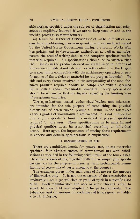
V. CLASSIFICATION AND TOLERANCES
1. GENERAL
One of the most important phases of standardization of screw-
thread products is that of interchangeability. The direct result
of establishing a national thread system will be the elimination of
many unnecessary sizes. Of even more importance are the advan-
tages to be gained in the manufacture of interchangeable screw-
thread parts, which having been made in different manufacturing
plants at widely separated points, will assemble without difficulty
and in a manner which will insure proper operation of the mechan-
ism being produced.
(a) Strict Interchangeability.—Many manufacturers, pre-
vious to the war, were making interchangeable machine parts in
their own shops where there was but one master gage or reference
standard, but one individual who had authority to pass on parts
in dispute, and where it was possible to secure assembly and satis-
factory operation by fitting the parts.
The experience gained by manufacturers producing war mate-
rial has demonstrated the economic advantage of producing inter-
changeable parts, especially where large quantities of parts are
manufactured. In addition to the direct saving in the cost of
manufacture, the numerous other advantages to be gained will
make it mandatory that the procedure for producing interchange-
22 NATIONAL SCREW THREAD COMMISSION
able work as specified under the subject of classification and toler-
ances be explicitly followed, if we are to keep pace or lead in the
world's progress as manufacturers.
(6) Need of Definite Specifications.—The difficulties en-
countered in obtaining enormous quantities of war material needed
by the United States Government during the recent World Warhas pointed out to Government authorities, as well as manufac-
turers, the need of writing definite and complete specifications for
material required. All specifications should be so written that
the qualities in the product desired are stated in definite terms of
known measurable standards and correctly defined by the largest
tolerance limits compatible with the satisfactory operation or per-
formance of the articles or material for the purpose intended. Tothis end every factor involved in the acceptability of the manufac-
tured product required should be comparable within specified
limits with a known measurable standard. Every specification
should be so concise that no dispute regarding the limiting lines
of acceptance can arise.
The specifications stated under classification and tolerances
are intended for the sole purpose of establishing the physical
dimensions of screw-thread products. While under tolerances
various grades of workmanship are covered, it is not intended in
any way to specify or limit the material or physical qualities
required by the user. These specifications as to material and
physical qualities must be established according to individual
needs. Here again the importance of stating these requirements
in concise and definite specifications is emphasized.
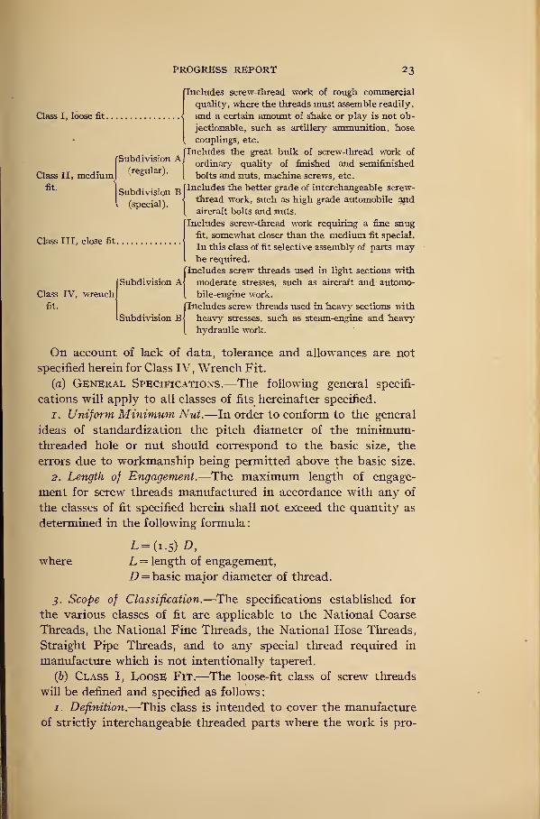
2. classification of fits
There are established herein for general use, unless otherwise
specified, four distinct classes of screw-thread fits with subdi-
visions as specified in the following brief outline of the four classes.
These four classes of fits, together with the accompanying specifi-
cations, are for the purpose of insuring the interchangeable manu-facture of screw-thread parts throughout the country.
The examples given under each class of fit are for the purpose
of illustration only. It is not the intention of the commission to
arbitrarily place a general class or grade of work in a specific class
of fit. Each manufacturer and user of screw threads is free to
select the class of fit best adapted to his particular needs. Thetolerances and dimensions for each class of fit are given in Tables
5 to 1 8, inclusive.
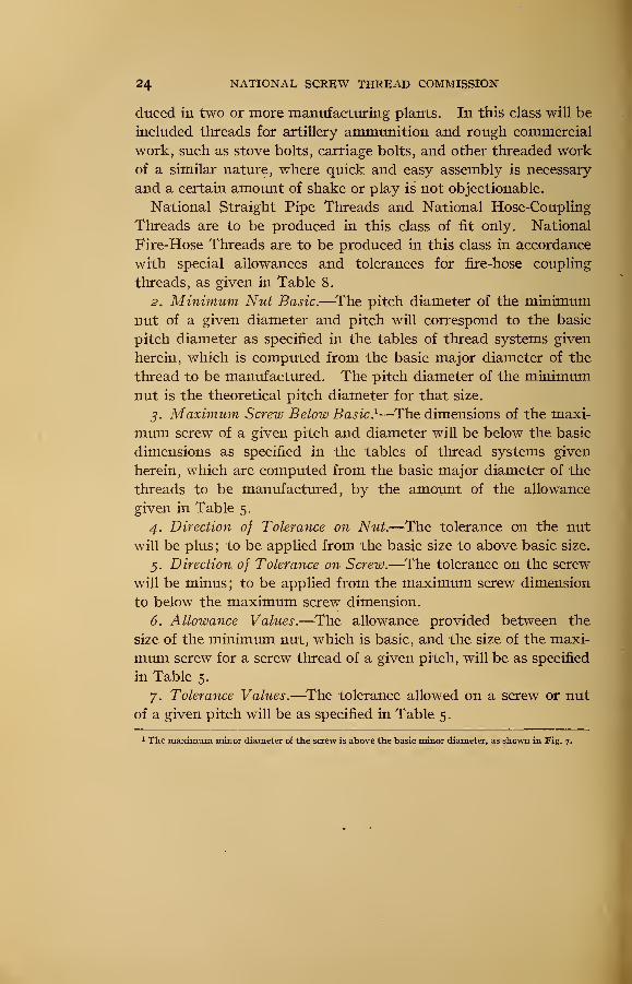
PROGRESS REPORT 23
Class I, loose fit.
Subdivision A
Class II, mediumfit.
Class III. close fit
Class IV, wrench
fit.
Includes screw-thread work of rough commercial
quality, where the threads must assemble readily,
and a certain amount of shake or play is not ob-
jectionable, such as artillery ammunition, hose
couplings, etc.
("Includes the great bulk of screw-thread work of
( ordinary quality of finished and semifinishedlregu ).
^ bolts and nuts, machine screws, etc.
Subdivision B Pncludes the better grade of interchangeable screw-
special) Itnrea<i work, such as high grade automobile and
[ aircraft bolts and nuts.
Includes screw-thread work requiring a fine snug
fit, somewhat closer than the medium fit special.
In this class of fit selective assembly of parts maybe required.
I
Includes screw threads used in light sections with
moderate stresses, such as aircraft and automo-
bile-engine work.
(Includes screw threads used in heavy sections with
heavy stresses, such as steam-engine and heavy
hydraulic work.
On account of lack of data, tolerance and allowances are not
specified herein for Class IV, Wrench Fit.
(a) General Specifications.—The following general specifi-
cations will apply to all classes of fits hereinafter specified.
1. Uniform Minimum Nut.—In order to conform to the general
ideas of standardization the pitch diameter of the minimum-threaded hole or nut should correspond to the basic size, the
errors due to workmanship being permitted above the basic size.
2. Length of Engagement.—The maximum length of engage-
ment for screw threads manufactured in accordance with any of
the classes of fit specified herein shall not exceed the quantity as
determined in the following formula:
L=(i. 5 ) D,
where L = length of engagement,
D = basic major diameter of thread.
3. Scope of Classification.—The specifications established for
the various classes of fit are applicable to the National Coarse
Threads, the National Fine Threads, the National Hose Threads,
Straight Pipe Threads, and to any special thread required in
manufacture which is not intentionally tapered.
(b) Class I, Loose Fit.—The loose-fit class of screw threads
will be defined and specified as follows
:
1. Definition.—This class is intended to cover the manufacture
of strictly interchangeable threaded parts where the work is pro-
24 NATIONAL SCREW THREAD COMMISSION
duced in two or more manufacturing plants. In this class will be
included threads for artillery ammunition and rough commercial
work, such as stove bolts, carriage bolts, and other threaded workof a similar nature, where quick and easy assembly is necessary
and a certain amount of shake or play is not objectionable.
National Straight Pipe Threads and National Hose-Coupling
Threads are to be produced in this class of fit only. National
Fire-Hose Threads are to be produced in this class in accordance
with special allowances and tolerances for fire-hose coupling
threads, as given in Table 8.
2. Minimum Nut Basic.—The pitch diameter of the minimumnut of a given diameter and pitch will correspond to the basic
pitch diameter as specified in the tables of thread systems given
herein, which is computed from the basic major diameter of the
thread to be manufactured. The pitch diameter of the minimumnut is the theoretical pitch diameter for that size.
3. Maximum Screw Below Basic. 1—The dimensions of the maxi-
mum screw of a given pitch and diameter will be below the basic
dimensions as specified in the tables of thread systems given
herein, which are computed from the basic major diameter of the
threads to be manufactured, by the amount of the allowance
given in Table 5.
4. Direction of Tolerance on Nut.—The tolerance on the nut
will be plus; to be applied from the basic size to above basic size.
5. Direction of Tolerance on Screw.—The tolerance on the screw
will be minus; to be applied from the maximum screw dimension
to below the maximum screw dimension.
6. Allowance Values.—The allowance provided between the
size of the minimum nut, which is basic, and the size of the maxi-
mum screw for a screw thread of a given pitch, will be as specified
in Table 5.
7. Tolerance Values.—The tolerance allowed on a screw or nut
of a given pitch will be as specified in Table 5.
1 The maximum minor diameter of the screw is above the basic minor diameter, as shown in Fig. 7.
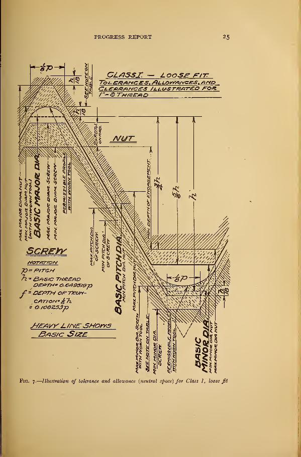
PROGRESS REPORT 25
Z OOSJE" FtTT
CLCARAKCe-S /jLl.LtSTBAT£0 FOR./"—& ST/ZD
7l - Bas/c thread
' =ttPTH of T/eury-
= 0/08Z53p
3/=>S/c S/ZE
FlG. 7.
—
Illustration of tolerance and allowance {neutral space) for Class I, loose fit
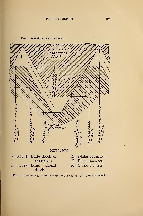
PROGRESS REPORT 27
NoTE.—Dotted line shows basic size.
f=0.0054=Basic depth of D=Major diameter
truncation E=Pitch diameter
h= .0325=Basic thread K=Minor diameter
depth
FlG. g.
—
Illustration of loosest condition for Class I, loose fit, y£ inch, 20 threads
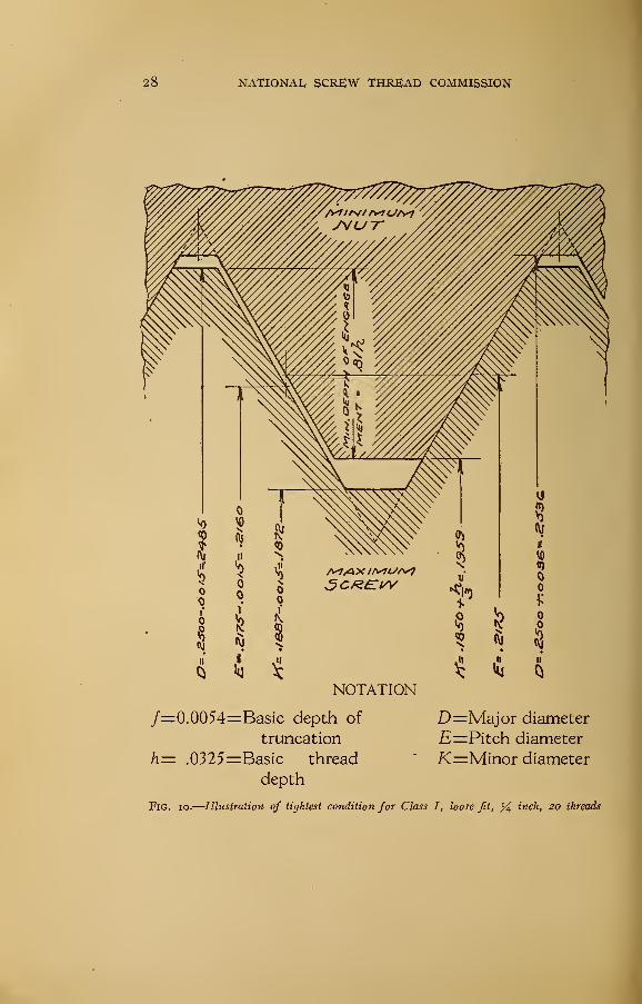
28 NATIONAL, SCREW THREAD COMMISSION
5 *M
NOTATION
/=0.0054=Basic depth of
truncation
h= .0325=Basic thread
depth
Fig. io.—Illustration of tightest condition for Class I, loose fit, % inch, 20 threads
D=Major diameter
E—Pitch diameter
K=Minor diameter
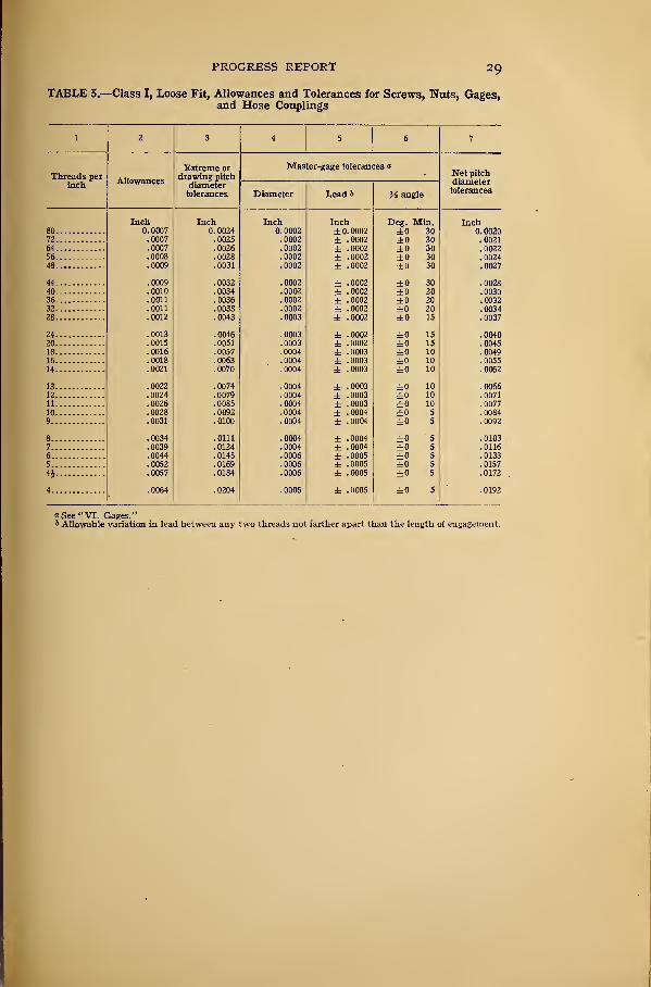
PROGRESS REPORT 29
TABLE 5.—Class I, Loose Fit, Allowances and Tolerances for Screws, Nuts, Gages,and Hose Couplings
1 2 3 4 5 • 6 7
Threads perinch
Allowances
Extreme ordrawing pitch
diametertolerances
Master-gage tolerancesNet pitchdiametertolerancesDiameter Lead b J£ angle
Inch Inch Inch Inch Deg. Min. Inch80 0. 0007 0. 0024 0. 0002 ±0.0002 ±0 30 U. Uu£U72 . 0007 . 0025 .0002 ± 0002 ±0 30 . 002164 !ooo7 !0026 0002 ± 0002 ±0 30 '.0022
56 .0008 .0028 !ooo2 ± 0002 ±0 30 .002448 . 0009 . 0031 .0002 ± 0002 to 30 . 0027
44 .0009 . 0032 .0002 ± 0002 ±0 30 . 002840 . 0010 . 0034 .0002 ± 0002 ±0 20 . 003036 !oon !0036 . 0002 ± 0002 ±0 20 !o03232 .0011 .0038 !ooo2 ± 0002 ±0 20 .003428 . 0012 . 0043 .0003 ± 0002 ±0 15 . 0037
24 . 0013 .0046 .0003 ± 0002 ±0 15 . 004020 . 0015 . 0051 .0003 ± 0002 ±0 15 . 004518 !ooi6 !o057 .0004 ± 0003 ±0 10 !o04916 .0018 .0063 .0004 ± 0003 ±0 10 .005514 .0021 .0070 .0004 ± 0003 ±0 10 .0062
13 .0022 .0074 .0004 ± 0003 ±0 10 .006612 .0024 .0079 .0004 ± 0003 ±0 10 .007111 .0026 .0085 .0004 ± 0003 ±0 10 .007710 .0028 .0092 .0004 ± 0004 ±0 5 .00849 .0031 .0100 .0004 ± 0004 ±0 5 .0092
8 .0034 .0111 .0004 ± 0004 ±0 5 .01037 .0039 .0124 .0004 ± 0004 ±0 5 .01166 .0044 .0145 .0006 ± 0005 ±0 5 .0133
5 .0052 .0169 .0006 ± 0005 ±0 5 .0157
4i .0057 .0184 .0006 ± 0005 ±0 5 .0172
4 .0064 .0204 .0006 ± 0005 ±0 5 .0192
"See "VI. Gages."6 Allowable variation in lead between any two threads not farther apart than the length of engagement.
30 NATIONAL SCREW THREAD COMMISSION
os « En Bii
tv O OH iH NgOHOOHHjad '
*
*
o woinom oocoo ooooo o ooooTfowo NviNON in o m o in ooooo oooto vo d h in Hixnoa r\j m r- o cm m o in o in o m o
r-< h (M cm co co --j- m in ^omcoh nuinon in o
So • • ••
co cn vo vo co cm co co in tj-
hhnnn cocotfinm IOMJiOh
o o co m mco oo m o o _ _ _oo co din o momess m t
—' - —
- o co m oo o
r . ^S O CO S
So ' '•
co co o o md lomNkom <o cm o o co notoo oooO vo co d co vo d cm in oo i-< r-» co d in o oo ^ o vo co oo ootVOOHHVl HN^-OVO CO m CO O CO H UD r-H£J H^H<-i h h mm co co in m ^onodoh Nint^-Oro m t-» o
HH H H H CM CM N N CO
JJiflNOOOlH2> o o o o hSoa
in m m m o h r-« «-h co«hNNCOCM NOOOt^lOCM IO d CM COtOM/lHrHiH pHrHpg CMCOCO-^-m
1 CM 00 d vO iflNOHrt OOO- Tj- CM CTi Ollflt^U-'t 00 00 OO• ffiHtM't voocor-cM mom1 vo co d O HtnocoH co vo co
*i-i r-< l-H t-H CM CM CM CM
d Tt- m oo oocm tj- m in oo
SgSSSSSo ' *
"
a
r-- d d in_ _ -<J- Tf- r-c O T}- O O 00 CO N (\J 1^. -H [> Cv VO VDVOr»coNooN vof hoco vo m cm co cm r-. h o in in r»c-c*»i-i^voooth r- co d in o vo co o i—< co in d cm in o co oo co»-1 1~* < >—< cm cm co co "^f" m m vo co d o ^miocon co m oo
H »—5 »—5 •—< >—< CM (M CM (M
00 vO vO vO,_ CO 00 t- oSoooohSo • •
•
tmo cm oo oo vo >—i m m u- -»3- Tt-vo cm vo oo m o r- m co co vo vo vocomor^oo i-icomcoco momIT) (DNCO Ol HCOlflNO CM LO o-
i-J 1-J t-iH CVJ CM fM CM
.—< t-- rj- d dvo vo vo r-wmvoNcoov
2 o o o o oSo •
•
CM CM d d d CO CM f- COTTOI-Om NInOvONO CO *N d IOOiQhNw H H CM CO CO •>*•
vO r* I> t>. -fl-
N^invONin vo £*» oo d
Tj- vo in ^ Tf Tj-mdcodd dddd i—• co m o CM c— CMocomc-o cm t>-
H i-i h H N CM CM CM*
tJ-CMC^-h^r_ d d r- in cox5 tj- in «d oo2 o o o o o
m m o o ONvoinc?cm oo o vo oo co m m o codHcoinr- co oo co dO H H t-H H cm cm co co ^j-
h «o ~* cm cm rj- n-COTT0OI>t> CO OO COtj- vo vo oo co u- dO CM T O d i—I CO VO
HH H HH CM CM CM
i-i co in co coXh CO CO CM O COcu m vo r- oo d
jjj]o o o o o
yd ' ' ""
vovovovocm t--moo^j-d d m vo cm coco 1-- co r- tMvot^-cot^ o m co ind cm co vo oo ^a-dTrom ripoco*-*o -<-« i-h i-i cm cm co «*- in vo c- co d c- d d cm c*.
VO vO vo
t-> TT VO
I a>
a
vo co m tj-
aj m d» oo d OjS o o o o H 3tj-tj- mvot>do
d co o vo voOCMCOHHtj- o- d co co1—" co m oo o
CM VO VO CO COW (M CO "fl" c*-
_£h O O O O Hvo vO vO vO O
H CM CM CM CM
<—< VO d CM CMca r- d >—
< tJ-j)voncj\ohjgOOOHH . _ - . o cm m c- dCM CO m VDNCOOtO
co vo om in co oo ci—< »o —> o- r-< cm cm ccm vo r—i m o in o iCM ^" t>- d CM U-t-C1—5 1—3 t-H i—5 CM CM CM C
CO CM O Oc/i
cm in oo i-c
fll ("- OO d i—• CMJgOOO HHd d r- r>. in d cm oo h ti- cm d vo hvo <m co rj- co ocomt>o CMt-HvOHcovooohtj- h r> co d vo cM-^-c^dcMH i—I i—I CM CM CO CO -3- m VO t-« 00 d H
H VO 00 CO COvo m -"i- tj-d T d tj-CM U- t>. d CM
* H CM CM C
c- vo in
h cm co m «»f c CM CM CM CM CO
PROGRESS REPORT 31
it!
1
I
s"
1
1
9
8
,§S§S3 ***** 1111 IIIII IIII
Jills IIIII IIIII IIIII IIII
illlll lllll IIIII IIIII IIIII IIII
iiiiii mis 11111 iisii mil 1111
3
I
illlli IIIII IIIII IIIII Hill IIII
IpIII IIII! mi 11111 11111 1111
illlll lllls IIIII IIIII IIIII IIII
illlli Illli IIIII IIIII IIIII IIII
lllil IIIII IIIII IIIII IIIII IIII^^^^^ NNNN
IpIII Islfl iini 11111 11111 mi
Iplil lllil IIIII lllil IIIII IIII
11111 mn mm 11111 11111 1111
IIII IIIII IIPI IIII
SSSSS JSSSS 22222 222s
I
g
1E
I
5
II11
1
ft
1!
If
32 NATIONAL SCREW THREAD COMMISSION
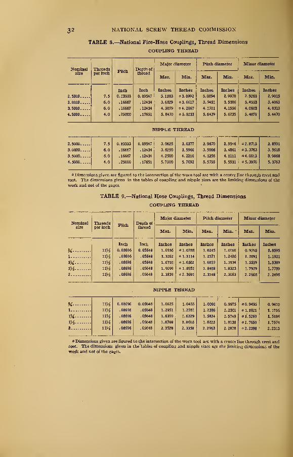
TABLE 8.—National Fire-Hose Couplings, Thread Dimensions
COUPLING THREAD
Major diameter Pitch diameter Minor diameter
Nominal ThreadsPitch
Depth of
size per inch threadMax. Min. Max. Min. Max. Min.
Inch Inch Inches Inches Inches Inches Inches Inches
2.5000.
.
7.5 0. 13333 0. 09547 3. 1183 13.0992 3.0094 2.9970 2.9263 2.9015
3.0000 6.0 . 16667 . 12434 3. 6829 a 3. 6617 3. 5451 3. 5306 3.4353 3.4063
3. 5000 6.0 . 16667 . 12434 4.3079 a 4. 2867 4. 1701 4. 1556 4.0603 4.0313
4.5000 , 4.0 .25000 . 17651 5. 8470 a 5. 8133 5.6439 5.6235 5.4878 5.4470
NIPPLE THREAD
2.5000.
,
7.5 0. 13333 0. 09547 3. 0625 3.0377 2.9670 2.9546 a 2. 8715 2.8591
3.0000,
.
6.0 . 16667 . 12434 3. 6250 3. 5960 3. 5006 3. 4861 a 3. 3763 3.3618
3. 5000 6.0 . 16667 . 12434 4.2500 4.2210 4. 1256 4.1111 « 4. 0013 3.9868
4.5000 4.0 .25000 . 17651 5. 7500 5. 7092 5. 5735 5. 5531 a 5. 3970 5. 3763
"Dimensions given are figured to the intersection of the worn tool arc with a center line through crest androot. The dimensions given in the tables of coupling and nipple sizes are the limiting dimensions of the
work and not of the gages.
TABLE 9.—National Hose Couplings, Thread Dimensions
COUPLING THREAD
Major diameter Pitch diameter Minor diameter
Nominal Threads Depth of
size per inchPitch
threadMax. Min. Mas. Min. " Max. Min.
Inch Inch Inches Inches Inches Inches Inches Inches
H ny2 0. 08696 0.05648 1.0936 a 1. 0788 1. 0245 1.0160 0. 9765 0.9595
l ny2 .08696 . 05648 1. 3262 a 1.3114 1.2571 1.2486 1.2091 1.1921
1M ny2 .08696 . 05648 1.6710 a 1. 6562 1.6019 1. 5934 1.5539 1.5369
m ny2 .08696 . 05648 1.9099 a 1.8951 1. 8408 1.8323 1. 7929 1.7759
2 ny2 . 08696 . 05648 2.3839 a 2. 3691 2. 3148 2.3063 2.2668 2. 2498
NIPPLE THREAD
% ny2 0. 08696 0. 05648 1. 0625 1. 0455 1. 0060 0. 9975 0.9495 0. 9410
1 uy2 . 08696 . 05648 1.2951 1.2781 1.2386 1.2301 a 1. 1821 1. 1736
m ny2 . 08696 . 05648 1.6399 1. 6229 1.5834 1.5749 a 1. 5269 1. 5184
iy2 ny2 .08696 . 05648 1.8788 1.8618 1.8223 1.8138 a 1. 7659 1. 7574
2 ny2 . 08696 . 05648 2.3528 2.3358 2.2963 2. 2878 a 2. 2398 2.2313
o Dimensions given are figured to the intersection of the worn tool arc with a center line through crest androot. The dimensions given in the tables of coupling and nipple sizes are the limiting dimensions of the
work and not of the gages.
PROGRESS REPORT 33
(c) Class II-A, Medium Fit (Regular).—This class of screw-
threads will be defined and specified as follows:
/. Definition.—The medium-fit class, Subdivision A, Regular,
is intended to apply to interchangeable manufacture where the
threaded members are to assemble nearly, or entirely, with the
fingers and where a moderate amount of shake or play between
the assembled threaded members is not objectionable. This
class will include the great bulk of fastening screws for instru-
ments, small arms, and other ordnance material, such as gun car-
riages, aerial bomb-dropping devices, and interchangeable ac-
cessories mounted on guns; also machine screws, cap screws, and
screws for sewing machines, typewriters, and other work of a
similar nature.
2. Minimum Nut Basic.—The pitch diameter of the minimumnut of a given diameter and pitch will correspond to the basic
pitch diameter as specified in tables of thread systems given
herein which is computed from the basic major diameter of the
thread to be manufactured.
3. Maximum Screw Basic.—The major diameter and pitch
diameter of the maximum screw of a given pitch and diameter
will correspond to the basic dimensions as specified in tables of
thread systems given herein which are computed from the basic
major diameter of the thread to be manufactured.
4. Direction of Tolerance on Nut.—The tolerance on the nut will
be plus; to be applied from the basic size to above basic size.
5. Direction of Tolerance on Screw. 2—The tolerance on the screw
will be minus ; to be applied from the maximum size to below max-imum size.
6. Zero Allowance.—The allowance between the pitch diameter
of the maximum screw and the minimum nut will be zero for all
pitches and all diameters.
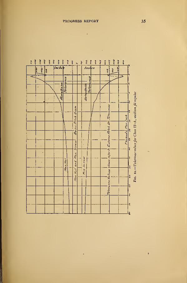
7. Tolerance Values.—The tolerance for a screw or nut of a
given pitch will be as specified in Table 10.
The maximum minor diameter of the screw is above the basic minor diameter, as shown in Fig. n.
12071 °-=21- 3
34 NATIONAL SCREW THREAD COMMISSION
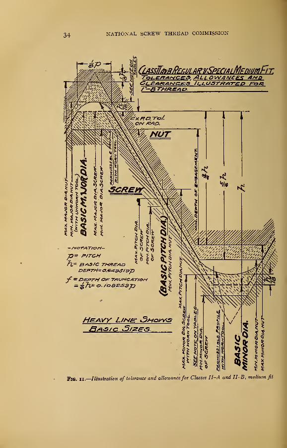
CjLASsW/lvRPErJJLARVSPECfAtMFniUfilFlT.» AL L O W/?A/f£
,% 41AIDt Jl-i.U-5TfZ/*TED /=•<=>/g
^Z?= P/TGH
•f= JDE*>r*i TftVrtCAT/OH
R©. II.
—
Illustration of tolerance and allowancefor Classes II-A and II-B, medium fit
PROGRESS REPORT
36 NATIONAL SCREW THREAD COMMISSION
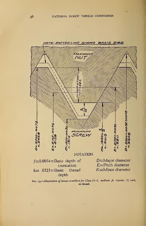
MOTE: GOTT£n LINE <5HOhY*5 SASfC <S/2Z^
NOTATION
/=0.0054=Basic depth of D=Major diameter
truncation E=Pitch diameter
h= .0325=Basic thread K^Minor diameter
depth
Fig. 13.
—
Illustration of loosest conditionfor Class II-A, medium fit regular, % incK20 threads
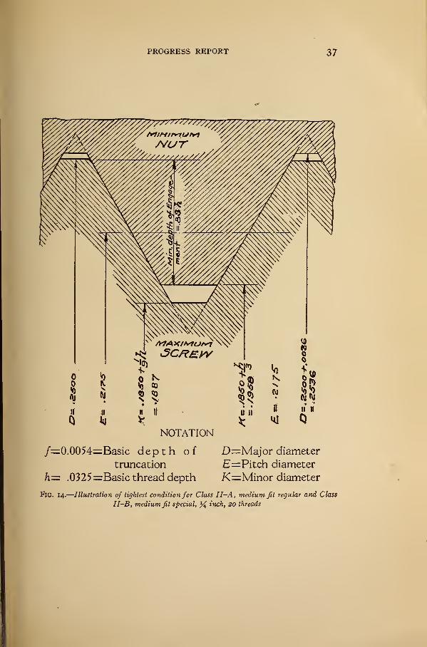
PROGRESS REPORT 37
NOTATION
/=0.0054=Basic depth oftruncation
h= .0325=Basic thread depth
D=Major diameter
E=Pitch diameter
K=Minor diameter
FlG. 14.
—
Illustration of tightest condition for Class II-A, medium fit regular and Class
II-B, medium fit special, % inch, 20 threads
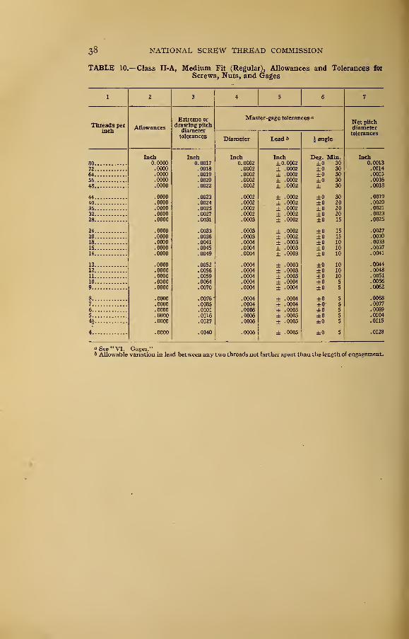
38 NATIONAL SCREW THREAD COMMISSION
TABLE 10.—Class II-A, Medium Fit (Regular), Allowances and Tolerances for
Screws, Nuts, and Gages
1 2 3 4 5 6 7
Threads perinch
Allowances
Extreme or
drawing pitchdiametertolerances
Master-gage tolerances aNet pitchdiametertolerances
Diameter Lead & § angle
T t.Inch Inch Inch Inch Deg. Min. Inchft ftnnn 0. 0017 n ftnfti
0- 0UU2 ±0.0002 ±0 30 0013
72 .0000 .0018 .0002 ± 0002 ±0 30 i0014
64 .0000 .0019 .0002 ± 0002 ±0 30 .0015
56 0000 . 0020 .0002 ± 0002 ±0 30 0016oooo . 0022 .0002 ± 0002 ± 30 0018
44 0000 . 00_ 3 . 0002 ± 0002 ±0 30 . 0019
40 ioooo .0024 .0002 ± 0002 ±0 20 !0020
36 .0000 .0025 .0002 ± 0002 ±0 20 .0021
32 9999 . 0027 .0002 ± 0002 ±0 20 0023
28 . oooo . 0031 .0003 ± 0002 ±0 15 0025
24 . 0000 . 0033 .0003 ± 0002 ±0 15 0027
20 .0000 .0036 .0003 ± 0002 ±0 15 !(H)30
18 .0000 .0041 .0004 ± 0003 ±0 10 .0033
16 .0000 .0045 .0004 ± 0003 ±0 10 .0037
14 .0000 .0049 .0004 ± 0003 ±0 10 .0041
13 .0000 .0052 .0004 ± 0003 ±0 10 .004412 .0000 .0056 .0004 ± 0003 ±0 10 .0048
11 .0000 .0059 .0004 ± 0003 ±0 10 .0051
10 .0000 .0064 .0004 ± 0004 ±0 5 .0056
9 .0000 .0070 .0004 ± 0004 ±0 5 .0062
8 .0000 .0076' .0004 ± 0004 ±0 5 .0068
7 .0000 .0085 .0004 ± 0004 ±0" 5 .0077
6 .0000 .0101 .0006 ± 0005 ±0 5 .0089
5 .0000 .0116 .0006 ± 0005 ±0 5 .0104
4J .0000 .0127 .0006 ± 0005 ±0 5 .0115
4 .0000 .0140 .0006 ± 0005 ±0 S .0128
a See "VI. Gages."6 Allowable variation in lead between any two threads not farther apart than the length of engagement.
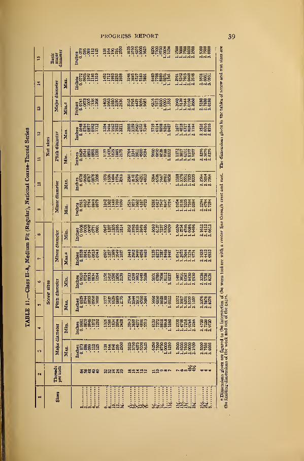
PROGRESS REPORT 39
a "1
sssaiQ ssssal BgSls sIrss lllll illgogsaa assss sssss ssasa sssgs ses
-a-
i11
""iS'SS SffiSS'SS 2SS"Sd SSSJslsaa 35S§§ Silsss Iglia Ssgll sis
aJC
%1 ijlllsl IIIIl lllll IIIII llff III
a
i\iiInches
0.
0648.0764 .0877 .0982
.
1112
.1204 .1464 .1662 .1922 .2211
.
2805.3389 .3960 .4552 .5140 .5719 .6914 .8098 .9264
1.
0407
1.
1657
1.
4018
1.
6317
1.
8684
2.
1184
2.
3516
2.
6016
2.
8516
a 'i
jinn sin iiiii iiiii mm in
s
!!i
iiiiii iisi iiiii iiiii ma ma
\ 3 mm iiiii iiiii iiiii iiiii in
CO
!
*
iiiiii iiiii iiiii iiiii iiiii in
r-»
J! § iiiiii iiiii iiiii iiiii iiiii in
s
*o
!]Mjinn aim iiiii mil mil in
VJ i] IIIIII sills iiiii iiiii sim in
;iijtllls IIIII IIIII IIIII lllll III
n-
ifSggSS S28§§ 111 IIIII IIIII III
!!to
ss5§s sssss aasaa as 01"" r.»«^
IJcinVyi JJs'a'i hsshsshs i»J5 S^IlL;^
IIiJSo•21
11
4o
n]
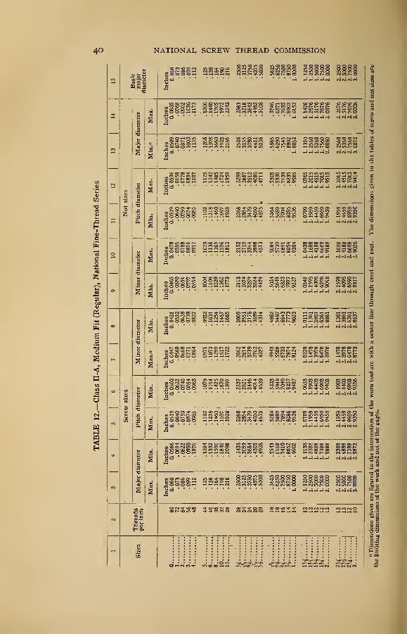
NATIONAL SCREW THREAD COMMISSION
lesss s§is§ mil mil §§in 1111
i
i
a
?!
Hill 11111 Jill! !!II§ lilf
mis iiiii iiiii iiiii mil mm
mil siiii nils iiiii iii§§ iiii
iiiii mil mil iiiii mil mi
mil iiiii urn urn mil mi
iiiii iiiii mil iiiii iiiii iiii
iiiii urn ism iiiii iiiii iiii
iiiii iiiii iiiii mil iiiii iiii
mil urn iiiii imi urn mi
Hill mil iiiii mil iiiii iiii
iim iiiii imi imi imi mi
leu, iii§ iim |i|f§ mi
1!
iSo
SSSSS 22222 2222
;22 inbwss HS^i^J ^SS^
PROGRESS REPORT 41
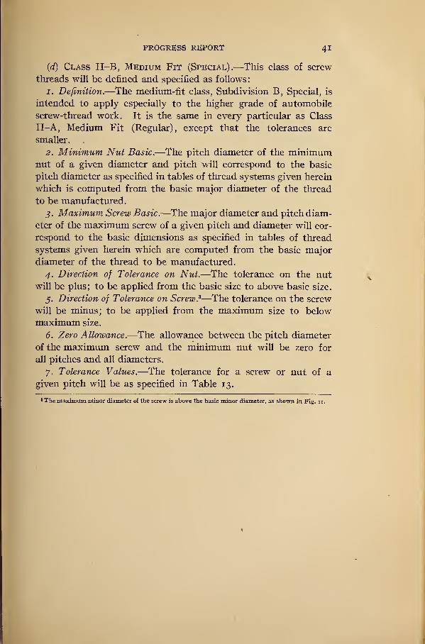
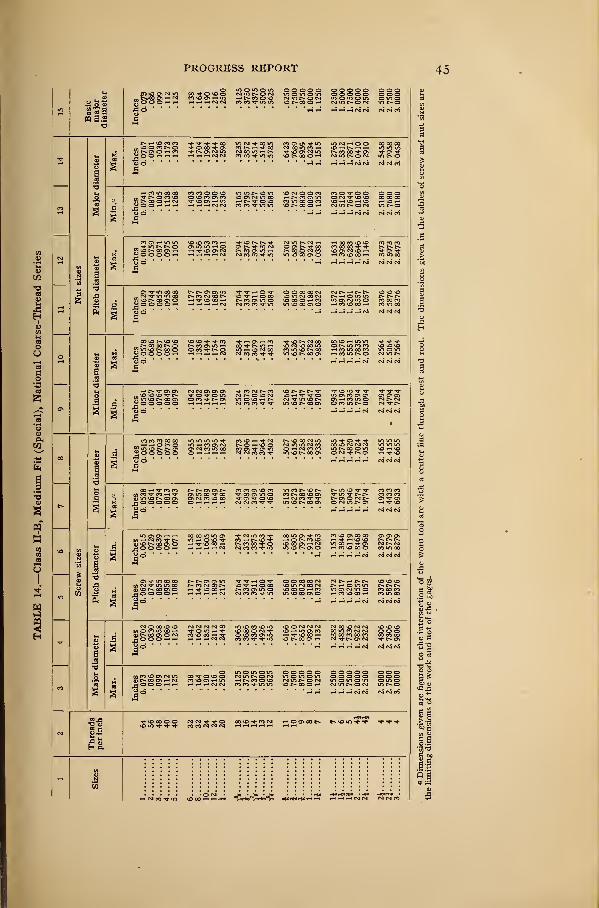
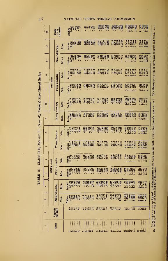
(d) Class II-B, Medium Fit (Special).—This class of screw
threads will be defined and specified as follows:
1. Definition.—The medium-fit class, Subdivision B, Special, is
intended to apply especially to the higher grade of automobile
screw-thread work. It is the same in every particular as Class
II-A, Medium Fit (Regular), except that the tolerances are
smaller.
2. Minimum Nut Basic.—The pitch diameter of the minimumnut of a given diameter and pitch will correspond to the basic
pitch diameter as specified in tables of thread systems given herein
which is computed from the basic major diameter of the thread
to be manufactured.
3. Maximum Screw Basic.—The major diameter and pitch diam-
eter of the maximum screw of a given pitch and diameter will cor-
respond to the basic dimensions as specified in tables of thread
systems given herein which are computed from the basic major
diameter of the thread to be manufactured.
4. Direction of Tolerance on Nut.—The tolerance on the nutwill be plus; to be applied from the basic size to above basic size.
5. Direction of Tolerance on Screw. 3—The tolerance on the screw
will be minus; to be applied from the maximum size to below
maximum size.
6. Zero Allowance.—The allowance between the pitch diameter
of the maximum screw and the minimum nut will be zero for
all pitches and all diameters.
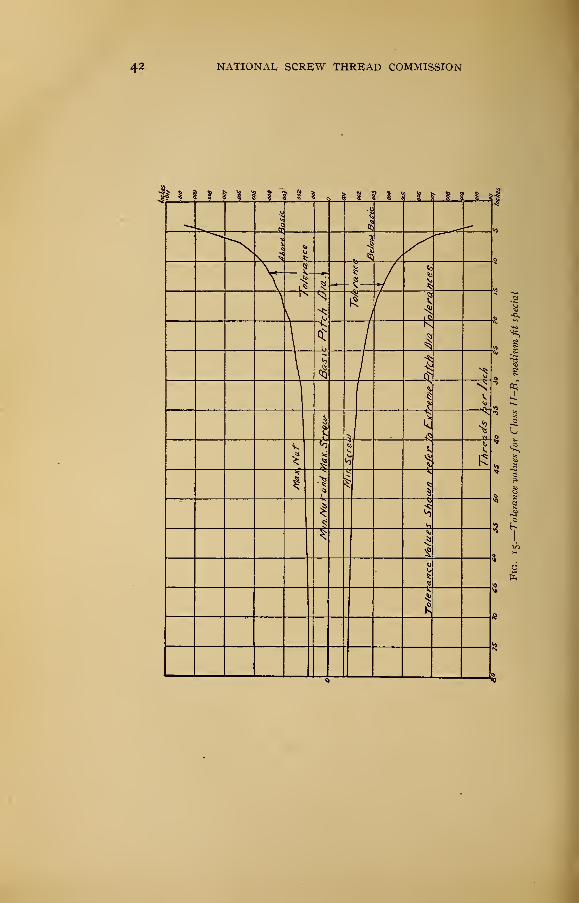
7. Tolerance Values.—The tolerance for a screw or nut of a
given pitch will be as specified in Table 13.
3 The maximum minor diameter of the screw is above the basic minor diameter, as shown in Fig. u.
42 NATIONAL SCREW THREAD COMMISSION
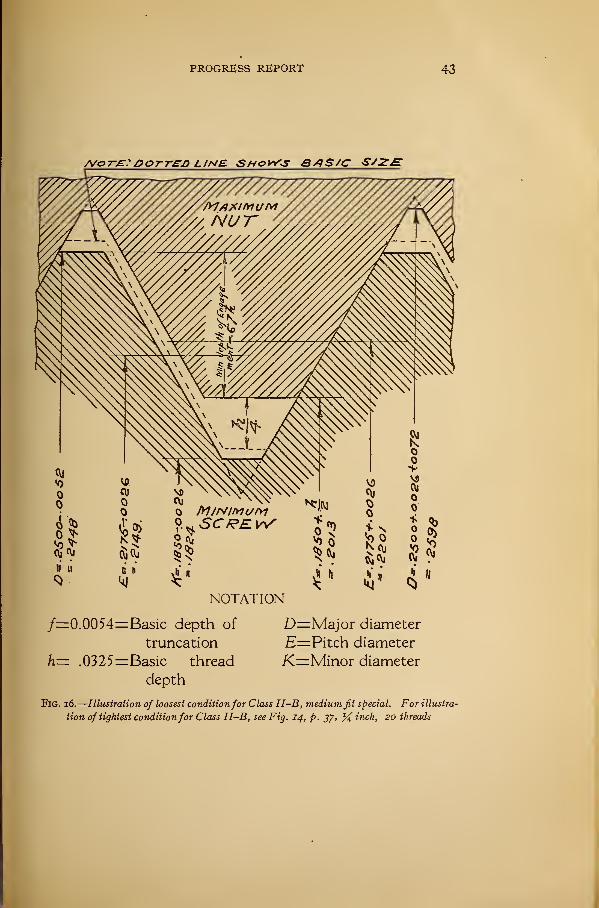
PROGRESS REPORT 43
A/& 7~£r:DorTED L 1NB SHOWS BAS/C S/Z£
NOTATION
/=0.0054=Basic depth of D=Major diameter
truncation E= Pitch diameter
h= .0325=Basic thread X=Minor diameter
depth
Fig. 16.
—
Illustration of loosest conditionfor Class II-B, medium fit special. For illustra-
tion of tightest conditionfor Class II-B, see Fig. 14, p. 37, % inch, 20 threads
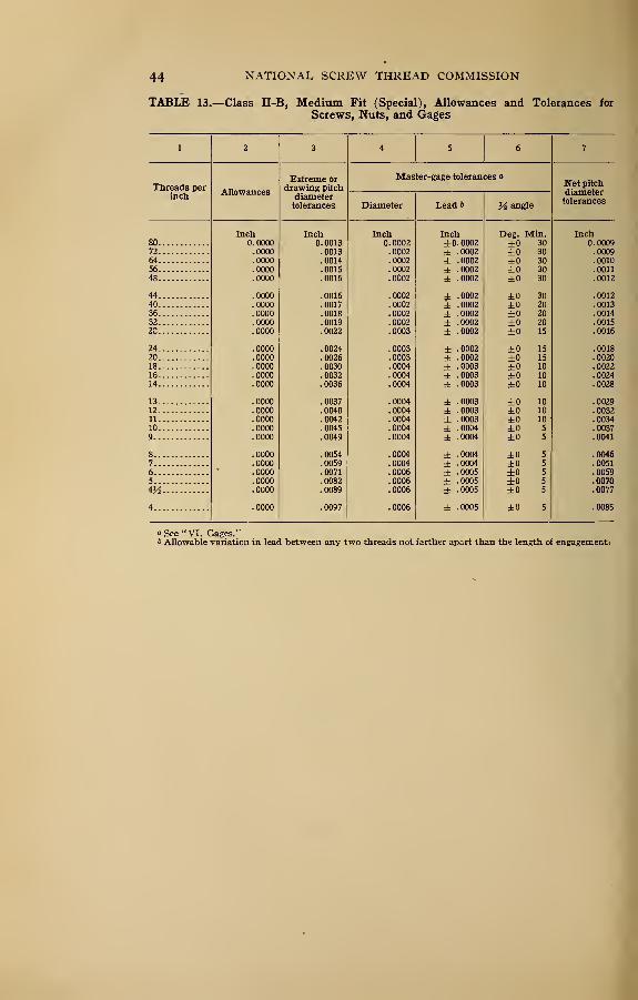
44 NATIONAL SCREW THREAD COMMISSION
TABLE 13.—Class II-B, Medium Fit (Special), Allowances and Tolerances for
Screws, Nuts, and Gages
1 2 3 4 5 6 7
Threads perinch
AllAllowances
Extreme ordrawing pitch
diametertolerances
Master-gage tolerancesjn et pitcudiametertolerances
Diameter Lead 6 M angle
Inch Inch Inch Inch Dee. Min. Inch80 0. 0000 0.0013 0. 0002 ±0. 0002 ±0 30 0. 000972 .0000 .0013 .0002 ± .0002 ±0 30 .000964 .0000 .0014 .0002 ± .0002 ±0 30 .001056 .0000 .0015 .0002 ± .0002 ±0 30 .001148 .0000 .0016 .0002 ± .0002 ±0 30 .0012
44 .0000 .0016 .0002 ± .0002 ±0 30 .001240 .0000 .0017 . 0002 ± .0002 ±0 20 .001336 .0000 .0018 .0002 ± .0002 ±0 20 .001432 .0000 .0019 .0002 ± .0002 ±0 20 .00152C .0000 .0022 . 0003 i . 0002 ±0 15 .0016
24 .0000 .0024 .0003 ± .0002 ±0 15 .001820 .0000 .0026 .0003 4- .0002 ±0 15 .002018 .0000 .0030 .0004 ± .0003 ±0 10 .002216 .0000 .0032 .0004 ± .0003 ±0 10 .002414 .0000 .0036 .0004 ± .0003 ±0 10 .0028
13 .0000 .0037 .0004 ± .0003 ±0 10 .002912 .0000 .0040 .0004 ± .0003 ±0 10 .003211 .0000 .0042 .0004 ± .0003 ±0 10 .003410 .0000 .0045 .0004 ± .0004 ±0 5 .00379 .0000 .0049 .0004 ± .0004 ±0 5 .0041
8 .0000 .0054 .0004 ± .0004 ±0 5 .00467 .0000 .0059 .0004 ± .0004 ±0 5 .00516 .0000 .0071 .0006 ± .0005 ±0 5 .00595 .0000 .0082 .0006 ± .0005 ±0 5 .00704^ .0000 .0089 .0006 ± .0005 ±0 5 .0077
4 .0000 .0097 .0006 ± .0005 ±0 5 .0085
a See "VI. Gages."& Allowable variation in lead between any two threads not farther apart than the length of engagement.
if]
ii
PROGRESS REPORT
.msa 3*§§s mi mil urn in
45
If
nisi mil nil mil gull in
iiiii mil mil mil urn m_5 rj <n3 c-icsicj
mil mil mis iiiii mis in
I
I
iiiii siiis iiiii iiiii iiiii in
mil iiiii urn mil iiin in
iiiii urn mil iiiii iiiii in
§§!§§ nisi mil urn mil in
IIIII till! IIIII IIIII IIIII 111
mil iiiii mil iiiii iiiii in
iiiii Sim iiiii urn mil in
mil iiiii iiiii mis urn in
§8ssa »sg§§ IIIII IIIII IIIII III
II
nn~N° 22322 32 I
~'<vi >o'ob22-« "CntHS-tA-C ^^^nST STrfm
NATIONAL SCREW THREAD COMMISSION
2111
»lg§§2 SSSfs IIIII Hill ggiil S||l
MgS|g| SgSgS ggggg SSSgg S|||§ ssssJoooSS 2SS3S SnnJS RSSSo SSsSSS SSSS
—2
' i
mm iiiii ma nm iiiii mm
a
i;iiInches
0.
0532.0653 .0773 .0889
.
1001.1118 .1235 .1478 .1716 .1950
.
2290
.
2878.3503 .4076 .4701 .5294 .5919 .7126 .8322 .9572
1.0749
1.
1999
1.
4499
1.
6999
1.
9499
2.
1999
2.
4499
2.
6999
2.
9395
a! 1
,ii§§! mil iim mii nm mi
s
iijllil! IIIII IIIII IIIII IIIII
.mil iiiii iiiii iiiii iim mi
00
1Mjinn iiiii iiiii iiiii nil sin
1iiiisi mil iiiii iiiii iiiii mi
ii ijinn mm iiiii mm iiiii mi
inlIIIII IIIII IIIII lllff IIIII IIII
!
«iiini iiiii mil iiiii iiiii §n§
C3
i|iiii3 iim iiiii iim nil
1SSSS™ SSigSSS fSSSSS 22SSS 22222 2222
i
..... ..... ..... -.,
© er> W in' vo co S 2 HvHSc^iH^-*^ H^atin^i-sei-i ^h^T^h*^ cvi (NTe^eSVi >
II
PROGRESS REPORT 47
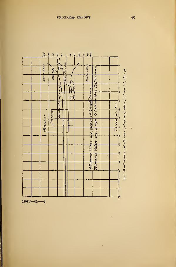
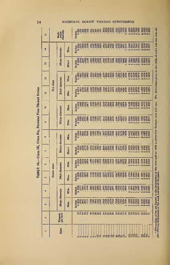
(e) Class III, Close Fit.—The close-fit class of screw threads
will be defined and specified as follows:
1. Definition.—This class is intended for threaded work of the
finest commercial quality, where the thread has practically no
back lash, and for light screwdriver fits. In the manufacture of
screw-thread products belonging in this class it will be necessary
to use precision tools, selected master gages, and many other re-
finements. This quality of work should, therefore, be used only
in cases where requirements of the mechanism being produced
are exacting, or where special conditions require screws having a
precision fit. In order to secure the fit desired it may be neces-
sary in some cases to select the parts when the product is being
assembled.
2. Minimum Nut Basic.—The pitch diameter of the minimumnut of a given diameter and pitch will correspond to the basic
pitch diameter as specified in tables of thread systems given herein
which is computed from the basic major diameter of the thread
to be manufactured.
j. Maximum Screw Above Basic.—The major diameter and
pitch diameter of the maximum screw of a given diameter and
pitch will be above the basic dimensions as specified in tables of
thread systems given herein which are computed from the basic
major diameter of the thread to be manufactured by the amountof the allowance (interference) specified in Table 16.
4. Direction of Tolerance on Nut.—The tolerance on the nut
will be plus ; to be applied from the basic size to above basic size.
5. Direction of Tolerance on Screw.—The tolerance on the screw
will be minus; to be applied from the maximum screw dimensions
to below the maximum screw dimensions.
6. Allowance Values.—The allowance (interference) provided
between the pitch diameter of the minimum nut, which is basic,
and that of the maximum screw, which is above basic, will be as
specified in Table 16.
7. Tolerance Values.—The tolerance for a screw or nut of a
given pitch will be as specified in Table 16.
48 NATIONAL, SCREW THREAD COMMISSION
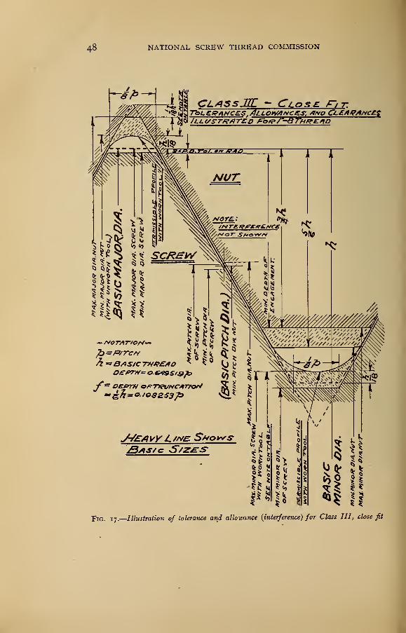
CLASSJK - Close. F> t.Allownc£s, *f*o CL£APAr<e£.$
'"-3Thread
FlG. 17.
—
Illustration of tolerance and allowance (interference) for Class III, close fit
PROGRESS REPORT 49
12071°—21-
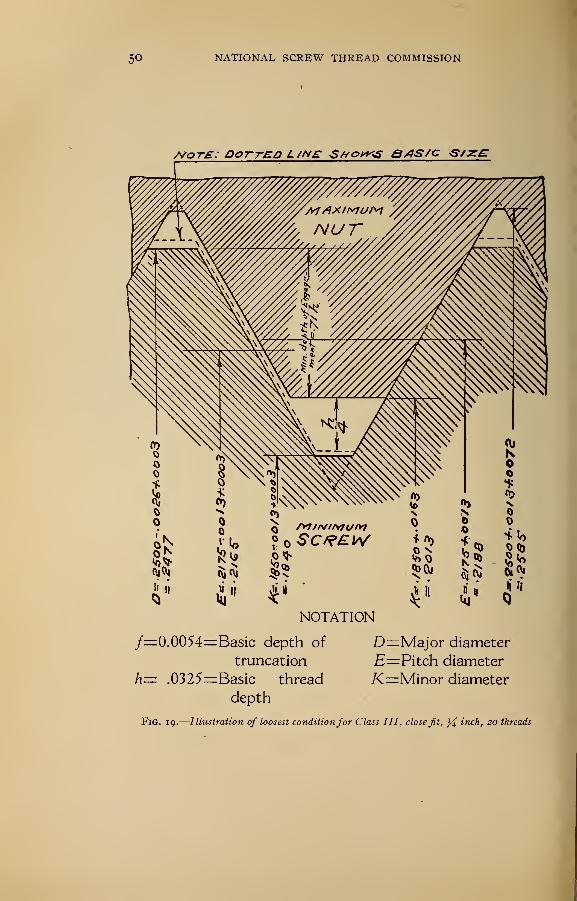
5° NATIONAL, SCREW THREAD COMMISSION
/vote: dotted L /ne Shocks e/is/c S/zrE
NOTATION
/=0.0054=Basic depth of
truncation
.0325=Basic thread
depth
h=
D=Major diameter
E=Pitch diameter
K=Minor diameter
Fig. 19.
—
Illustration of loosest conditionfor Class III , close fit, inch, 20 threads
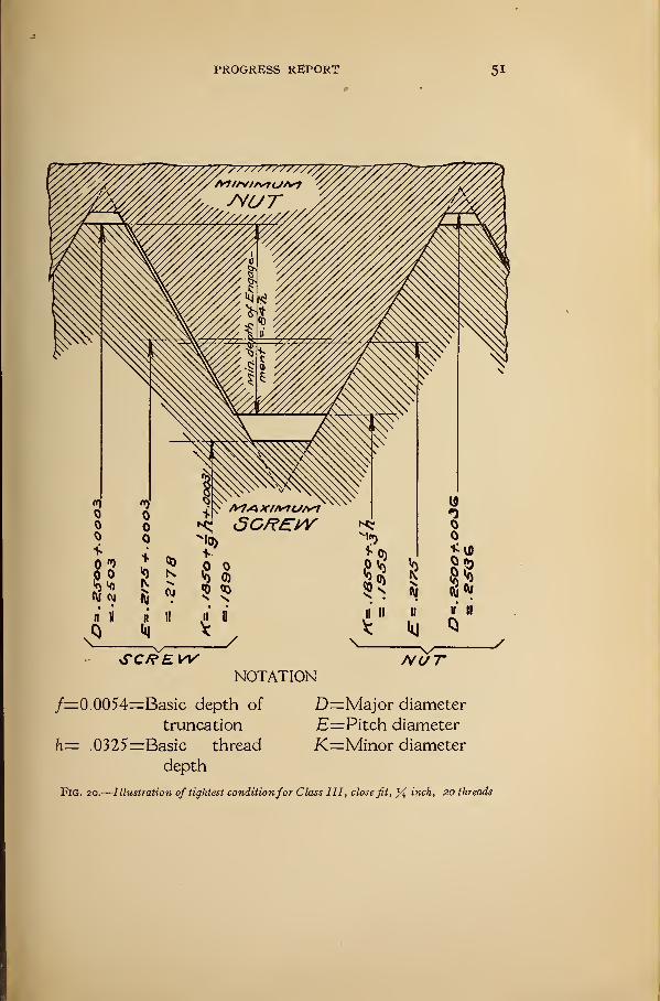
PROGRESS REPORT 5
1
NOTATION
/=0.0054=Basic depth of D=Major diameter
truncation E— Pitch diameter
h= .0325=:Basic thread K=Minor diameter
depth
Fig. 20.
—
Illustration of tightest conditionfor Class III, close fit, % inch, 20 threads
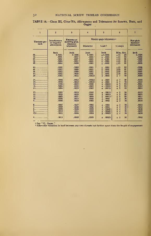
52 NATIONAL SCREW THREAD COMMISSION
TABLE 16.—Class III, Close Tit, Allowances and Tolerances for Screws, Nuts, andGages
1 2 3 4 5 6 7
Threads perinch
Interferenceor negativeallowances
Extreme ordrawing pitch
diametertolerances
Master-gage tolerances "
Net pitchdiametertolerances
Diameter Lead f> angle
Inch Inch Inch Inch Min. Sec. Inch80 0. 0001 0. 0006 0. 0001 ±0.0001 ±15 00 0.000472 .0001 .0007 .0001
'
± 0001 ±15 00 .000564 .0001 .0007 .0001 0001 ±15 00 .000556 0002 0007 .0001 ± 0001 ±15 00 000548 !o002 .0008 . 0001 ± 0001 ±15 00 ]0006
44 .0002 .0008 . 0001 ± 0001 ±15 00 .000640 .0002 .0009 . 0001 ± 0001 ±10 00 .000736 .0002 .0009 .0001 ± 0001 ±10 00 .000732 0002 . 0010 .0001 ± 0001 ±10 00 000828 .0002 .0011 .00015 ± 0001 ± 7 30 iooos
24 .0003 .0012 .00015 ± 0001 ± 7 30 .000920 .0003 .0013 .00015 ± 0001 ± 7 30 .001018 .0003 .0015 .0002 ± 00015 ± 5 00 .001116 0004 0016 .0002 ± 00015 ± 5 00 001214 !0004 .0018 .0002 ± 00015 ± 5 00 !ooi4
13 . 0004 .0019 .0002 ± 00015 ± 5 00 .001512 .0005 .0020 .0002 ± .00015 ± 5 00 .001611 .0005 .0021 .0002 ± 00015 ± 5 00 .001710 .0006 .0023 .0002 ± 0002 ± 2 30 .00199 .0006 .0024 .0002 ± 0002 ± 2 30 .0020
8 .0007 .0027 .0002 ± 0002 ± 2 30 .00237 .0008 .0030 .0002 ± 0002 ± 2 30 .00266 .0009 .0036 .0003 ± 00025 ± 2 30 .00305 .0010 .0041 .0003 ± 00025 ± 2 30 .0035
4Ji .0011 .0044 .0003 ± 00025 ± 2 30 .0038
4 .0013 .0048 .0003 ± 00025 ± 2 30 .0042
a See "VI. Gages."6 Allowable variation in lead between any two threads not farther apart than the length of engagement
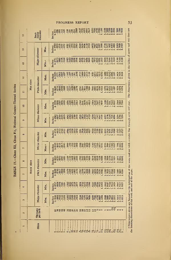
PROGRESS REPORT 53
o I- °
S g 6
•o
1/5
J3H
o
ad
5
s9
„ r~- co co id on r-i in — - -™ O o o *—» i—i •-< n n nn^inm id r- oo o i-<
O V) OOOOO O O O O vD oooon m o m o ~ — — — — — — ~O •£> ro in r- O OOOOO ooo- - - -- o m o
in t> oHH HHHNC
o co co m in in m ro co m oicioom nntno o io in on cn onlOOMOOl CO s- P-» CO 00 MinONCllO O ^D CO O CO CO t- CO »JD >J3 OOO
- — - - - CO «—< t-» tJ- id ON f - —COOhN Tj-iOCJif4> O O 1-H 1-H 1-t HHHNN•So
co co ^i" m in vor*ooo-~< co u
tH t-i r-i t-I iH N N N N PI
t co m oo oo co ro o o o in m r-- id m io ro o o co coo.. * n o ro o io co on co ooNNinco i-* c- co on — '
MnwOhN tJ- ID On y-> U"> i-t £» TP O >D COD O O r-< t-h riHtiNN CO CO T " _
O O OOO. l£HD COOOCO
OO O CO hiDhiOmdoh eg in c— o ro mt-o
i co co tj- in imocodO
- m co co c^NffiOMfl Tp tP i—i O O O 00 00 CO NNrHtiD'tnOco io m co oo co t^^-"Ou
Tp vO 00 .-i C- CO CMC O ID 00 O —« CO
P- OOvQ
i-H rlHHHN CO CO CO
VDIS^HO lO in CO TP »—< ON •—' CO TP l£5 p- CM 00 COlO-H
.--COOOr-O l> P5 OMD r-l CO N ITj rH *o rvi i« f-ir^in«>ny3tNcoo o o ^ i> o mn^Noo co
u o
CO CO VO^OUoo r~* co un oo co in o ucr. h romtvo cm m c
HHHrtN CM CO CM
iH r- Cl 3 ON ON tP CO CO P- CO vDNNNTf ^ i£nn 't tJ- TP Tp tPC^OvDCM iD «-< TP tP O inOCOOC^ On On cnOiDhI> MTfUTOC- On <-* CO in O CM f- CMco co tP tP m io oo on ocomr-o c-.
rHrtHHM CM CO CO
i— CO CO 0O CO VO v£> O O O >—i iD CO iO P-» CO tP CMC CM NCOHOO C~ t-NNricoH lONiriH'* on ro co co cm m co co in r— oo o r- co co i-. i-<™in\OP»c* o CTicmco^ooo cocyiTi-c^m o >-h co co co id cg co o m cnn>------ - COCOf iniDr-COO^ ONTTP-CJl HtJ-vO2?00000 O 1-1 1-H *-<
•So
- co o co o on co co m m tj- in m m_ j- co 1—
1 tp dm/1 en oi tp co o o tp r- on r» o miomoooojinior-cocr- on co co 00 i-cti^oid t-< ro co tp in octnocmn•OOOOO owi-ii—>i-i ro co co tp tp m iDt^coci o cm in r- 0*1
CO O CTi t—' ' (?0>00i/lOJ CNJ CO TP in 00 l£> CO OO CO lOOjiDt-COOi O h*\OCOh t-- CO CO tP O VDC_e o o o o t-h i-< 1-- --
- --
< —I CO CM CO CO
i 00 n co m tt o<oo>oo on on P . _OJ CO Tp in >£> ON C~~ CO CO CJi t~~ lO TP i—I O CO *D *j
cd vd r~- co cti o HTfiowi-i i>ncnr ~_C O O O O i-H i-< r-4 i-« 1-1 CO OO CO CO t
3 00 On ON ON
HHlHlHN CO C
r*.00\OTpTP CO CM CT\ ON C» 00C/3
t-< Tp p- O CO ID W£> COP* ON _ _ni p* 00 cn 1— co co o co »—1 Tj- r— co o m
CO lO O CO O 00 CO 00tp id o\ id o m oco on m CM Tpt>- On i-<
CM CO CO Tp TP in i£3I>COOih
00 r~ co co ro c-*t*.c*-CO CO CM CM 1-H r-l
'i" CT> tJ- CTi T}- CJi "^J" cnCM tJ- |>. cjl CM ON
HrHHHN rococo
t—I CM CM CM CM CO CM CO CO CO CO "t ON if O U*nDlDI>CO COONOHH CO CO COt/3 co us on cm m cot o<oo cm m o co inomom o o •—1 »-i 1-1 hhhcu t> 00 on co co >d on 1—< in HNmo»D cm m r— o cm m o in o in omoj3 o o o 1-1 «-« ihhhncm co co m in vdc-cooh comc-ocM m o^ O «h«h »-5 1—4 1-5 co co rococo
Ha
1 CO i-c O O 00 I>
d»S2X -Ks-es-p 1 ~4 *4 (M N CM
S oo
a S
5 a
S So.b
NATIONAL SCREW THREAD COMMISSION
4>
To™ •« 2 am a 1
,§§§s3ass§§ mil mil inn mi'r4 ^^rt^oj csiracvim
f
mmmm iiiii inn mi! mi
Jills lllll Islil IIIII
slllli lalll IIIII IIIII 11111 sill
II5
mil imi mil miiiiiiiiiii
siiiii iiiii iiiii iiiii mil nil
1
mrnmrn mm iiiiiiiiinii,-i _J ,-i ^ N(VltsilNi
llilll llfll iiiii lllll iiiii Sill
,§iiii ism imi nil mi! mi
J!iiiii iiiii iiiii iiiii iiiii mi
1
iiiii mi! mil urnmm mi
Pills iiiii mil iiiii iiiii mm
I
""8
9IISo
I1
SSSS? 22222 222S
I;S2 i^nsi «i^J ^S^SU
PROGRESS REPORT 55
(/) Class IV, Wrench Fit.—The wrench-fit class of screw
threads will be defined and specified as follows:
1. Definition.—This class is intended to cover the manufacture
of threaded parts one-fourth inch diameter or larger which are to
be set or assembled permanently with a wrench. Inasmuch as for
wrench fits, the material is an important factor in determining the
fit between the threaded members, there are provided herein two
subdivisions for this class of work, namely, Subdivision A and
Subdivision B. These two subdivisions differ mainly in the
amount of the allowance (interference) values provided for dif-
ferent pitches.
Subdivision A of Class IV, Wrench Fit, provides for the pro-
duction of interchangeable wrench-fit screws or studs used in light
sections with moderate stresses, such as for aircraft and auto-
mobile engine work.
Subdivision B of Class IV, Wrench Fit, provides for the pro-
duction of interchangeable wrench-fit screws or studs used in
heavy sections with heavy stresses, such as for steam-engine and
heavy hydraulic work.
2. Minimum Nut Basic.—The pitch diameter of the minimumnut of a given diameter and pitch for threads belonging in either
Subdivision A or Subdivision B will correspond to the basic pitch
diameter as specified in tables of thread systems given herein,
which is computed from the basic major diameter of the thread
to be manufactured.
j. Maximum Screw above Basic.—The major diameter and pitch
diameter of the maximum screw of a given diameter and pitch
for threads belonging in either Subdivision A or Subdivision Bwill be above the basic dimensions as specified in tables of thread
systems given herein, which are computed from the basic major
diameter of the thread to be manufactured, by the amount of the
allowance (interference) provided.
4. Direction of Tolerance on Nut.—The tolerance on the nut
will be plus; to be applied from the basic size to above basic size.
5. Direction of Tolerance on Screw.—The tolerance on the screw
will be minus ; to be applied from the maximum screw dimensions
to below maximum screw dimensions.
6. Allowance and Tolerance Values not Included.—At the present
time the commission does not have sufficient information or data
to include in its progress report values for tolerances and allow
ances for wrench fits. It is hoped, however, that sufficient infor-
mation resulting from investigation and research will enable the
56 NATIONAL SCREW THREAD COMMISSION
commission to decide, at an early date, the allowance and toler-
ance values for the two classes of wrench fits included herein,
which will be applicable to the various materials and which will
meet the requirements found in manufacture of machines or
product requiring wrench fits.
3. TOLERANCES
There are specified herein for use in connection with the various
fits established, three different sets of tolerances as given in Tables
5, io, 13, and 16.
(a) Tolerances Represent Extreme Variations.—The tol-
erances as hereinafter specified represent the extreme variations
allowed on the work. 4
(b) Pitch Diameter Tolerances Include Lead and AngleVariations.—The tolerance limits established represent, in reality,
the sizes of the "Go" and "Not Go" master gages. Errors in
lead and angle which occur on the threaded work can be offset bya suitable alteration of the pitch diameter of the work. If the
"Go" gage passes the threaded work interchangeability is secured
and the thread profile may differ from that of the "Go" gage in
either pitch diameter, lead, or angle. The " Not Go " gage checks
pitch diameter only, and thus insures that the pitch diameter is
such that the fit will not be too loose. (See Appendix 5 for fur-
ther explanation.)
(c) Class I and Class II Tolerances Permit the Use of
Commercial Taps.—The tolerances established for Class I, Doose
Fit, and Class II, Medium Fit, permit the use of commercial taps
now obtainable from various manufacturers. For Class III,
Close Fit, in which it is desired to produce a hole close to the basic
size, it is recommended that a selected tap be used.
(d) Pitch Diameter Tolerances on Screw Same as on Nut.—The pitch diameter tolerances provided for a screw of a given
class of fit will be the same as the pitch diameter tolerances pro-
vided for a nut corresponding to the same class of fit.
(e) Tolerances 6n Major Diameter of Screw Twice thePitch Diameter Tolerances.—The allowable tolerances on the
major diameter of screws of a given classification will be twice the
tolerance values allowed on the pitch diameters of screws of the
same class.
(/) Tolerances on Minor Diameter of Screw.—The mini-
mum minor diameter of a screw of a given pitch will be such as to
* Recommendations and explanations regarding the application of tolerances are given in Appendix 5.
PROGRESS REPORT 57
result in a basic flat (}4 X p) at the root when the pitch diameter
of the screw is at its minimum value. (Note.—When the maximumscrew is basic, the minimum minor diameter of the screw will be
below the basic minor diameter by the amount of the specified
pitch diameter tolerance.)
The maximum minor diameter may be such as results from the
use of a worn or rounded threading tool, when the pitch diameter
is at its maximum value. In no case, however, should the form
of the screw, as results from tool wear, be such as to cause the screw
to be rejected on the maximum minor diameter by a "Go" ring
gage, the minor diameter of which is equal to the minimum minordiameter of the nut.
(g) Tolerances on Major Diameter op Nut.—The maximummajor diameter of the nut of a given pitch will be such as to result
in a flat one-third of the basic flat X p) when the pitch diameter
of the nut is at its maximum value. (Note.—When the minimumnut is basic, the maximum major diameter will be above the
basic major diameter by the amount of the specified pitch diameter
tolerance plus two-ninths of the basic thread depth.)
The nominal minimum major diameter of a nut will be above
the basic major diameter by an amount equal to one-ninth of the
basic thread depth plus the neutral space. This results in a
clearance which is provided to facilitate manufacture by permitting
a slight rounding or wear at the crest of the tap. In no case,
however, should the minimum major diameter of the nut, as re-
sults from a worn tap or cutting tool, be such as to cause the nut
to be rejected on the minimum major diameter by a "Go" plug
gage made to the standard form at the crest.
(h) Tolerances on Minor Diameter of Nut.—The tolerances
on minor diameter of a nut of a given pitch will be one-sixth of the
basic thread depth regardless of the class of fit being produced.
Xi) Illustration .—In Fig. 21 there are shown the various re-
lations previously specified for tolerances on both the screw andthe nut.
(j) Scope op Tolerance Specifications.—The specifications
establishing the various sets of tolerances for the different classes
of fit specified herein will apply to the manufacture of National
Coarse Threads, National Fine Threads, National Hose-Coupling
Threads, National Fire-Hose Coupling Threads, Straight Pipe
Threads, and wherever applicable to the production of all special
threads.
58 NATIONAL SCREW THREAD COMMISSION
Where tolerances are desired for a special thread and the pitch
is not listed in the tables given, the tolerance values should be
chosen corresponding to the number of threads per inch nearest
to that of the special thread being produced. Where the numberof threads per inch is midway between two of the pitches listed,
the tolerance corresponding to the coarser pitch should be used.
For instance, the tolerance on a screw having \i}4. threads per
inch would correspond to the tolerances specified for a screw of
ii threads per inch.
VI. GAGES
1. INTRODUCTORY
For the production of interchangeable threaded parts in large
quantities, as provided for by specifications given under the
subject of "Classification and Tolerances," it will be necessary to
employ an adequate system of measuring or gaging the parts
produced.
It is not the desire of the commission, nor is it wise at the
present time, to lay down hard-and-fast specifications of a gaging
system to meet the requirements of various manufacturers. Todo this would not only cause hardship in certain lines of industry,
but also would tend to limit progress in this important subject
connected so closely with quantity production. It is felt, how-
ever, that inasmuch as at the present time the use of gages is the
only known means of securing interchangeability, it is wise,
especially in view of the experience and education gained during
the recent World War, that certain fundamentals should be
adopted which will serve as a unification of various gaging
systems now in use by manufacturers in this country. A com-
plete gaging system which has been found adequate in the
production of war material is specified in detail in Appendix 6.
(a) Fundamentals.— (i) Standard Master Gage is the gage to
which all other gages and all dimensions of the mating parts are
ultimately checked or referred, either by direct check or bycomparative measurements.
It clearly establishes the low limit of the threaded hole and the
high limit of the screw at the point at which interference begins
between mating parts.
(2) The tolerance limits of the component as physically repre-
sented by the Limit Master Gages must never be exceeded as a
result either of errors or wear of the gages.
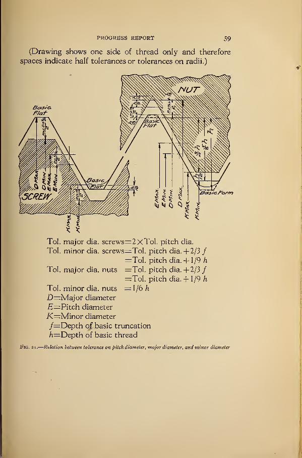
PROGRESS REPORT 59
(Drawing shows one side of thread only and therefore
spaces indicate half tolerances or tolerances on radii.)
Tol. major dia. screws=2xTol. pitch dia.
Tol. minor dia. screws=Tol. pitch dia. + 2/3 /=Tol. pitch dia. + 1/9 /i
Tol. major dia. nuts =Tol. pitch dia. +2/3 /=Tol. pitch dia. + 1/9 h
Tol. minor dia. nuts =1/6 h
D=Major diameter
E=Pitch diameter
i<=Minor diameter
/=Depth of basic truncation
h—Depth of basic thread
Fig. 2i.
—
Relation between tolerance on pitch diameter, major diameter, and minor diameter
6o NATIONAL SCREW THREAD COMMISSION
(3) "Go" gages are absolutely essential to prevent interference
of mating parts.
(4) "Not Go" gages are essential to prevent excess shake,
play, or looseness of mating parts as determined by the extreme
component limits.
(6) Gage Classification: i. Standard Master Gage.—TheStandard Master Gage is a threaded plug representing as exactly
as possible all physical dimensions of the nominal or basic size of
the threaded component. In order that the Standard Master
Gage be authentic, the deviations of this gage from the exact
standard should be ascertained and certified by the National
Bureau of Standards and, when used, its known errors should
be taken into account.
2. Limit Master Gages.—The Limit Master Gages are threaded
plugs representing as nearly as possible the exact limiting physical
dimensions of the threaded mating parts as established by the
specified tolerances. (For further information on limit gages
see Appendix 6.)
A complete set of Limit Master Gages, in the form of threaded
plugs, representing the maximum and minimum screw and nut
dimensions for both the coarse and the fine series, and for all
classes of fit, should be standardized by and kept at the National
Bureau of Standards for use in settling any controversies that
may arise with reference to the dimensions of other Limit Master
Gages. The maximum ("Not Go") gages should be made to the
maximum pitch diameter only. The major diameter and minor
diameter should not be greater than the minimum specified for
the minimum ("Go") gages. (See Appendix 6 (c) (5).)
3. Inspection Gages.—Inspection gages are for the use of the
purchaser in accepting the product.
4. Working gages.—Working gages are those used by the
manufacturer to check the parts produced as they are machined.
(c) Standard Temperature.—Gages and product should have
their correct nominal dimensions at 68° F.
VII. NATIONAL PIPE THREADS
1. INTRODUCTORY
The material on the subject of pipe threads presented here-
with was prepared by a special committee of the Committee of
Manufacturers on Standardization of Fittings and Valves, acting
in cooperation with pipe and gage manufacturers and the A. S.
PROGRESS REPORT 6l
M. E. committee on International Standards for Pipe Threads.
It was published in October, 191 9, under the title of "Manual on
American Standard Pipe Threads." It has been indorsed by
the American Society of Mechanical Engineers and the American
Gas Association, and is adopted by the commission with only
such changes as are necessary to bring it into conformity with
the remainder of the report.
2. NATIONAL STANDARD PIPE THREADS
(Formerly known as American Standard Pipe Threads)
Indorsed by:
Committee of Manufacturers on Standardization of Fittings and Valves, 1927-1928 Whitehall Building,
17 Battery Place, New York, N. Y. Chairman; Howard Coonley, Walworth Manufacturing Co., Boston,
Mass. Secretary: A. A. Ainsworth, 17 Battery Place, New York, N. Y.
Committee on Dimensions and Specifications: Chairman, A. M. Houser, Crane Co., Chicago, 111.
Committee on Lists and Classifications: Chairman, J. S. Mattimore, The Kelly & Jones Co., New York,
N. Y.
American Foundry & Construction Co., Pitts-
burgh, Pa.
American Valve Co., Coxsackie, N. Y.
Automatic Sprinkler Co. of America, 123 William
Street, New York, City.
Crane Co., Chicago, 111.
Darling Pump & Machinery Co. (Ltd.), Williams-
port, Pa.
Detroit Brass Works, Detroit, Mich.
Detroit Lubricator Co., Detroit, Mich.
Thomas Devlin Manufacturing Co., Philadelphia,
Pa.
Eddy Valve Co., Waterford, N. Y.
Essex Foundry, Newark, N. J.
The Fairbanks Co., New York, N. Y.
Stanley G. Flagg & Co., Philadelphia, Pa.
General Fire Extinguisher Co., Providence, R. I.
Illinois Malleable Iron Co., Chicago, 111.
Jarecki Manufacturing Co., Erie, Pa.
H. J. Kattenthaler, Philadelphia, Pa.
The M. W. Kellog Co., New York, N. Y.
The Kelly & Jones Co., New York, N. Y.
The Kennedy Valve Manufacturing Co.
N. Y.The Kerr Manufacturing Co., Walkerville,
tario, Canada.
Kuhns Bros., Dayton, Ohio.
Ludlow Valve Manufacturing Co., Troy, N. Y.The Lunkenheimer Co., Cincinnati, Ohio.
Malleable Iron Fittings Co., Branford, Conn.
T. McAvity & Sons (Ltd)., St. John, New Bruns-
wick.
McNab & Harlin Manufacturing Co., New York,
N. Y.
Elmira,
On-
Nelson Valve Co., Philadelphia, Pa.
Ohio Brass Co., Mansfield, Ohio.
Pacific Foundry Co., San Francisco, Calif.
Pittsburgh Valve and Foundry Const. Co., Pitts-
burgh, Pa.
Pittsburgh Valve and Fittings Co., Barberton,
Ohio.
The Wm. Powell Co., Cincinnati, Ohio.
The Pratt & Cady Co., (Inc)., Hartford, Conn.
The Stockham Pipe Fittings Co., Birmingham,
Ala.
Walworth Manufacturing Co., Boston, Mass.
The D. T. Williams Co., Cincinnati, Ohio.
R. D. Wood & Co., Philadelphia, Pa.
Pipe Manufacturers:
National Tube Co'., Pittsburgh, Pa.
Central Tube Co., Pittsburgh, Pa.
A. M. Byers Co., Pittsburgh, Pa.
Wheeling Steel & Iron Co., Wheeling, W. Va.
South Chester Tube Co., Chester, Pa.
Jones & Laughlin Steel Co., Pittsburgh, Pa.
Youngstown Sheet & Tube Co., Youngstown,Ohio.
Steel & Tube Co. of America, Chicago, 111.
U. S. Steel Products Co., New York, N. Y.
Gage Manufacturers:
Pratt & Whitney Co., Hartford, Conn.
Greenfield Tap and Die Corporation, Greenfield,
Mass.
Taft Peirce Manufacturing Co., Woonsocket, R. I.
History
The American Pipe-Thread Standard, also known as the American Briggs Standard,
was formulated by Robert Briggs prior to 1882.
Mr. Briggs for several years was superintendent of the Pascal Iron Works of Morris,
Tasker & Co., Philadelphia, and later was engineering editor of the Journal of the
Franklin Institute. After his death, a paper by Mr. Briggs containing detailed in-
formation regarding American Pipe and Pipe-Thread practice was read before the
Institution of Civil Engineers of Great Britain. This is recorded in the Excerptminutes, Volume EXXI, Session 1882-1883, Part 1.
62 NATIONAL SCREW THREAD COMMISSION
While, in a general way, American manufacturers were threading practically to
the Briggs Standard, in 1886 the manufacturers and the American Society of Mechan-
ical Engineers jointly adopted it in detail, and master gages were made. The standard
has since been in general use in the United States and Canada.
At various conferences later, American manufacturers and the American Society
of Mechanical Engineers established additional sizes, certain details of gaging, tol-
erances and special applications of the standard; also the formulas and dimensions
were tabulated more completely than was originally done by Mr. Briggs.
Outline of Standard
The National (American) Pipe-Thread Standard establishes the following:
Outside diameter of pipe,
Diameter of external (male) thread,
Diameter of internal (female) thread,
Profile of thread,
Pitch or lead of thread,
Length of thread,
Taper of thread,
Engagement (by hand) of external and internal threads,
Construction and use of gages,
Tolerances,
Use of taper threads,
Use of straight threads.
Tables of Dimensions
The dimensions of National (American) Pipe Threads are expressed in inches to
one one-hundred thousandth (0.00001) of an inch, and in millimeters to one one-
thousandth (0.001) of a millimeter.
While this is a greater degree of accuracy than is ordinarily used, the dimensions
are so expressed in order to eliminate errors which might result from less accurate
dimensions.
The relation between the inch and the meter used in calculating the dimensions
in these tables is that established by law in the United States and on record in the
Bureau of Standards, Department of Commerce, Washington, D. C. This is
1 meter=3o.37 inches exactly.
The metric equivalent of the inch resulting from this determination is
25.40005 millimeters= 1 inch.
Outside Diameter of Pipe
The outside diameter of pipe is given in Column D of the table of dimensions. Thesediameters should be very closely adhered to by pipe manufacturers.
Diameter of Taper Thread
The pitch diameters of the taper thread are determined by formulas based on the
outside diameter of pipe and the pitch of thread. These are as follows:
A=D-(o.osD+i.i)P.B=A-\-o.o62$L
1.
yl=pitch diameter of thread at end of pipe.
B=pitch diameter of thread at gaging notch.
Z)=outside diameter of pipe.
L^normal engagement by hand between external and internal threads.
P=pitch of thread.
Note.—The above formulas are not expressed in the same terms as the formula originally established
by Mr. Briggs, because they are used to determine pitch diameters, whereas the Briggs formula determined
the major (outside) diameter of the thread. However, both forms give identical results.
PROGRESS REPORT 63
Profile
The angle between the sides of the thread is 6o° when measured in the axial plane,
and the line bisecting this angle is perpendicular to the axis of the pipe, for taper or
straight threads. (See Fig. 22.)
The crest and root are truncated an amount equal to 0.033P. The depth of the
thread, therefore, is 0.8P. (See Fig. 22.)
Note.—While Mr. Briggs originally advocated a slightly rounded crest and root, the thread as applied
in the manufacture of gages and thread tools has always been slightly flattened at the crest and root.
While the crests on commercially manufactured external and internal threads would appear slightly
rounded when examined with a microscope, for all practical purposes they may be considered as sharp.
The roots of commercially manufactured threads are practically sharp when cut with new tools and
slightly rounded when cut with worn tools.
Pitch
The pitch of a screw thread is the distance from a point on the thread to a correspond-
ing point on the next thread, measured parallel to the axis.
Lead
The lead of a screw thread is the distance the screw will advance axially in one
revolution. It is expressed in terms of the number of threads in 1 inch and the numberof threads in 254 millimeters (254 mm equals 10 inches). On a single thread screw
the lead and pitch are identical.
Length of Thread
The length of the taper external thread is determined by a formula based on the
outside diameter of pipe and the pitch of the thread. This is as follows:
L2=(o.8D+6.8)P.
L2=length of effective thread.
£>=outside diameter of pipe.
P=pitch of thread.
Note.—The above formula is not expressed in the same terms as the one originally established by Mr.
Briggs, because it determines directly the length of effective thread which includes two threads slightly
imperfect on the crest, whereas the Briggs formula determined the length of perfect thread, the two threads
imperfect on the crest not being included in the formula. However, both forms give identical results.
Taper of Thread
The taper of the thread is 1 in 16 measured on the diameter.
Engagement Between Taper External (Male) and Internal (Female)Thread
The normal length of engagement between taper external and internal threads
when screwed together by hand is shown in Column Lxof Table 19.
This length is controlled by the construction and use of the gages.
Gages
Gages to properly maintain interchangeability of pipe threads should consist of
Standard Master, Reference, Inspection, and Working Gages. The dimensions andfunctions of these gages are outlined below.
Standard Master Gage
The Scandard Master Gage is a taper threaded plug gage. The roots of the threads
are cut to a sharp V or may be undercut below the sharp V to facilitate the making of
the thread. The crests are truncated an amount equal to 0.1P. (SeeFig. 25.) Other-
wise the gage is made to the dimensions given in Table 19. This gage is provided
64 NATIONAL SCREW THREAD COMMISSION
with the gaging notch as illustrated in Fig. 23. The Standard Master Gage is the gage
to which all other gages are ultimately referred either by transference of measure-
ments or direct comparison by engagement. It is intended primarily for gage and
thread tool manufacturers.Reference Gages
The Reference Gages consist of a plug gage, similar in all respects to the Standard
Master Gage, and two ring gages. One ring gage has a thickness equal to dimension
L lt is the same diameter at the small end as the small end of the plug gage, and is
flush with the plug gage at the small end and at the gaging notch when screwed on
tight by hand. (See Fig. 23.) The other ring gage has a thickness equal to dimen-
sion L2 , but is threaded for distance L2-L,. The distance equal to Lxis counterbored
and unthreaded. This gage is the same diameter at the large end as the large end of
the plug gage. (See Fig. 24.) The Reference Plug Gage is used to inspect inspection
and working taper threaded ring gages. The Reference Ring Gages are used to com-
pare the reference plug with the standard master plug or the inspection and working
plug gages with the reference plug gage.
Inspection Gages
Inspection Gages consist of one taper threaded plug gage and one taper threaded
ring gage. The roots of the threads are cut to a sharp V or may be undercut to facili-
tate making the thread. The crests are truncated an amount equal to 0.1P. (See
Fig. 27.)* The ring gage has a thickness equal to dimension L lt and the same diameter
at the small end as the small end of the plug gage. (See Fig. 26.)
Note.—The object of truncating the crests on gages (truncation 0.1P) is to insure that when gaging
commercial threads cut with a slightly dull tool the gage bears on the sides of the thread instead of on theroots.
Inspection Gages are for the use of the purchaser of pipe thread products. Whenused, the extreme tolerance on the work should be applied. This tolerance is 1%turns either way from the gaging notch in the case of internal threads inspected with
the inspection plug gage, and when inspecting external threads the tolerance is 1^turns either way from the small end of the inspection ring.
Working Gages
The Working Gages consist of one taper threaded plug gage and one taper threaded
ring gage. These gages are similar in all respects to the inspection plug and ring
gages. The Working Gages are used by the manufacturer to inspect his product. In
using the Working Gages the tolerance to be applied is one turn either way from the
gaging notch in case of internal threads inspected with the plug gage, and in the case
of external threads the tolerance is one turn either way from the small end of the
working ring gage.
Gaging Internal (Female) Threads
The Inspection and Working Plug Gages, Figs. 31 and 34, should screw tight byhand into the fitting or coupling until the notch is flush with the face. When the
thread is chamfered, the notch should be flush with the bottom of the chamfer. 'The
fitting or coupling is within the working or net tolerance if the working gage notch
is within one turn of the coupling or fitting face when screwed in tight by hand. In
the same way the coupling or fitting is within the inspection or extreme tolerance if
the inspection gage notch is within 1% turns of the coupling or fitting face whenscrewed on tight by hand.
This method of gaging is used either for taper internal threads or for straight internally
threaded couplings which screw together with taper external threads. (See Figs. 31
and 34.)
4 Otherwise the gages are made to the dimensions given in Table 19.
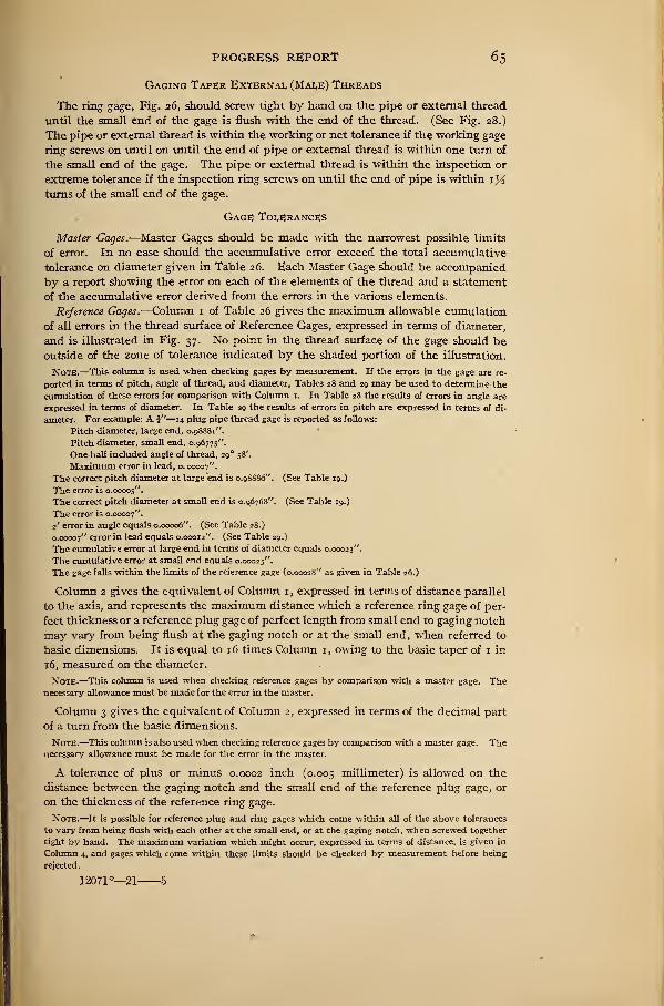
PROGRESS REPORT 65
Gaging Taper External (Male) Threads
The ring gage, Fig. 26, should screw tight by hand on the pipe or external thread
until the small end of the gage is flush with the end of the thread. (See Fig. 28.)
The pipe or external thread is within the working or net tolerance if the working gage
ring screws on until on until the end of pipe or external thread is within one turn of
the small end of the gage. The pipe or external thread is within the inspection or
extreme tolerance if the inspection ring screws on until the end of pipe is within zyi
turns of the small end of the gage.
Gage Tolerances
Master Gages.—Master Gages should be made with the narrowest possible limits
of error. In no case should the accumulative error exceed the total accumulative
tolerance on diameter given in Table 26. Each Master Gage should be accompanied
by a report showing the error on each of the elements of the thread and a statement
of the accumulative error derived from the errors in the various elements.
Reference Gages.—Column 1 of Table 26 gives the maximum allowable cumulation
of all errors in the thread surface of Reference Gages, expressed in terms of diameter,
and is illustrated in Fig. 37. No point in the thread surface of the gage should be
outside of the zone of tolerance indicated by the shaded portion of the illustration.
Note.—This column is used when checking gages by measurement. If the errors in the gage are re-
ported in terms of pitch, angle of thread, and diameter, Tables 28 and 29 may be used to determine the
cumulation of these errors for comparison with Column 1. In Table 28 the results of errors in angle are
expressed in terms of diameter. In Table 29 the results of errors in pitch are expressed in terms of di-
ameter. For example: A J"—14 plug pipe thread gage is reported as follows:
Pitch diameter, large end, 0.98881".
Pitch diameter, small end, 0.96775".
One-half included angle of thread, 29° 58'.
Maximum error in lead, o. 00007".
The correct pitch diameter at large end is 0.9S886". (See Table 19.)
The error is 0.00005".
The correct pitch diameter at small end is 0.96768". (See Table 19.)
The error is 0.00007".
2' error in angle equals 0.00006". (See Table 28.)
0.00007" error in lead equals 0.00012". (See Table 29.)
The cumulative error at large end in terms of diameter equals 0.00023".
The cumulative error at small end equals 0.00025".
The gage falls within the limits of the reference gage (0.00028" as given in Table 26.)
Column 2 gives the equivalent of Column 1, expressed in terms of distance parallel
to the axis, and represents the maximum distance which a reference ring gage of per-
fect thickness or a reference plug gage of perfect length from small end to gaging notch
may vary from being flush at the gaging notch or at the small end, when referred to
basic dimensions. It is equal to 16 times Column 1, owing to the basic taper of 1 in
16, measured on the diameter.
Note.—This column is used when checking reference gages by comparison with a master gage. Thenecessary allowance must be made for the error in the master.
Column 3 gives the equivalent of Column 2, expressed in terms of the decimal part
of a turn from the basic dimensions.
Note.—This column is also used when checking reference gages by comparison with a master gage. Thenecessary allowance must be made for the error in the master.
A tolerance of plus or minus 0.0002 inch (0.005 millimeter) is allowed on the
distance between the gaging notch and the small end of the reference plug gage, or
on the thickness of the reference ring gage.
Note.—It is possible for reference plug and ring gages which come within all of the above tolerances
to vary from being flush with each other at the small end, or at the gaging notch, when screwed together
tight by hand. The maximum variation which might occur, expressed in terms of distance, is given in
Column 4, and gages which come within these limits should be checked by measurement before being
rejected.
12071°—21 5
66 NATIONAL SCREW THREAD COMMISSION
Inspection Gages.—The tolerance on inspection gages will be the same as on reference
gages. (See Table 26.)
New Working Gages.—Column 5 of Table 27 gives the maximum allowable cumu-lation of all errors in the thread surface of new working gages, expressed in terms of
diameter, and is also illustrated in Fig. 37. No point in the thread surface of the gage
should be outside of the zone of tolerance indicated by the shaded portion of the
illustration.
Note.—This column is used when checking gages by measurement.
Column 6 gives the equivalent of Column 5, expressed in terms of distance parallel
to the axis, and represents the maximum distance which a new working ring gage
of perfect thickness or a new working plug gage of perfect length from small end to
gaging notch may vary from being flush at the gaging notch, or at the small end,whenreferred to basic dimensions. It is equal to 16 times Column 5, owing to the basic
taper of 1 in 16, measured on the diameter.
Note.—This column is used when checking working gages by comparison with a gage the error of whichis known. The necessary allowance must be made for this error.
Column 7 gives the equivalent of Column 6, expressed in terms of the decimal
part of a turn from basic dimensions.
Note.—This column is also used when checking working gages by comparison with a gage the error of
which is known. The necessary allowance must be made for this error.
A tolerance of plus or minus 0.0005 inch (0.0127 mm) is allowed on the distance
between the gaging notch and the small end of the working plug gage, or on the
thickness of the working ring gage.
Note.—It is possible for working plug and ring gages which come within all of the above tolerances to
vary from being flush with each other at the small end or at the gaging notch, when screwed together tight
by hand. The maximum variation which might occur, expressed in terms of distance, is given in Column8, and gages which come within these limits should be checked by comparison with reference gages before
being rejected.
It is also possible for working plug and ring gages which come within all of the above tolerances to vary
from being flush at the small end or at the gaging notch, when screwed tight by hand on a reference gage
which comes within the tolerances specified for references gages. The maximum variation which might
occur, expressed in terms of distance, is given in Column 9, and gages which come within these limits should
be checked by measurement before being rejected.
Worn Working Gages.—The maximum wear on working gages must not be more
than the equivalent of one-half turn from the basic dimensions.
In order that no work passed by the working gage shall be rejected by the inspection
gage, it will be necessary to discontinue the use of the working gage when it has worn
one-half turn. That is, the working gage should always be kept within the tolerance
of one-half turn from the basic dimensions.
Manufacturing Tolerance
The maximum allowable variation in the commercial product is one turn plus or
one turn minus from the gaging notch when using working gages. (See Figs. 29, 30,
32, and 33.) This is equivalent to a maximum allowable variation of one and one-
half turns from the basic dimensions, owing to the allowance of one-half turn on work-
ing gages.
National (American) Taper Pipe Threads
Taper external and internal threads are recommended for threaded joints for any
service.
PROGRESS REPORT 6 7
National Straight Pipe; Threads
Internal (Female).—Straight threaded internal wrought-iron or wrought-steel
couplings of the weight known as "standard" may be used with taper threaded pipe
for ordinary pressures, as they are sufficiently ductile to adjust themselves to the
taper external thread when properly screwed together. For dimensions see Table 20.
For high pressures, only taper external and internal threads should be used.
External (Male).—Straight external threads are recognized only for special appli-
cations such as long screws, tank nipples.
Long Screws
Long screws are used to a limited extent. This joint is not considered satisfactory
when subjected to temperature or pressure. In this application (see Fig. 35) the cou-
pling has a straight thread and must make a joint with a National (American) Taper
Pipe Thread.
In gaging, the National (American) Taper Working Plug Gage is used, allowing the
same tolerance from the notch as for a taper thread. (See Fig. 34.) The straight
thread on the pipe enters the coupling freely by hand, the joint being made by a
packing material between the locknut and the coupling. (See Fig. 35.)
It is necessary that the coupling be screwed on the straight external thread for the
full length of the coupling and then back until it engages the taper external thread.
Owing to the long engagement of thread, imperfections in pitch affect the fit whenthe coupling is screwed on the pipe its full length. Refinements of manufacture and
gaging to insure a properly interchangeable product are more costly than the commer-
cial use warrants; therefore, the use of this type of joint is not recommended.
Locknut Threads
Occasional requirements make it advisable to have a straight thread of the largest
diameter it is possible to cut on a pipe. This has been standardized and is known as
Maximum External and Minimum Internal Locknut Threads. For dimensions, see
Table 21. The "tank nipple" shown in Fig. 36 is an example of this thread. In this
application a National (American) Standard Taper Thread is cut on the end of the pipe
after having first cut the External Locknut Thread.
Symbols
The list of symbols given in Section II-3, together with additional symbols given
below, should be used in formulas for expressing relation of pipe threads and for use
on drawings, etc.
j4=pitch diameter of thread at end of pipe.
2J=pitch diameter of thread at gaging notch.
C^maximum pitch diameter external locknut thread.
C2=minimum pitch diameter internal locknut thread.
L1=distance from gaging notch to end of pipe=normal engagement by hand.
L2=length of effective thread.
D=nominal outside diameter of pipe=major diameter of pipe thread at L2 fromend of pipe.
<2=internal diameter of pipe.
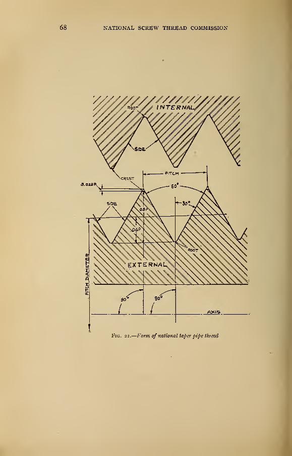
NATIONAL SCREW THREAD COMMISSION
Fig. 22.
—
Form of national taper pipe thread
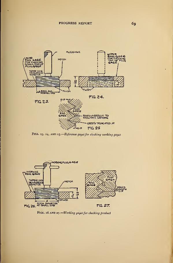
PROGRESS REPORT 69
Figs. 23, 24, and 25.
—
Reference gagesfor checking working gages
fhq. 26. AT aMAU- FIG. 2 7:
Figs. 26 and 27.
—
Working gagesfor checking product
y
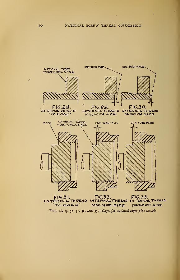
7o NATIONAL SCREW THREAD COMMISSION
NATIONAL TAPERWORKING 'RINC. GA Ct B
FIG.28.EXTERNAL TH REfii O
"TO G^Gf*
ONE TURN PLUS ONE TURN MINUS
FIC.S3. FIG.30.EATERNflLTHI?SflD EXTERNAL. TH(?EflOM/»XI/VIi"vl SIZE MINIMUM SIZE
FLUSHNATIONAL TAPE.RWORKING PLUG. GAG£ ONE TURN PLUS ONE TURN MINUS
FIG.3I. FIG.32. FIG.33.INTEI?NflUTHI7£/IO INT£I?NAUTHR£A0 INTERNAL THREAD
"ro 6fl6E* fvi/Qx/mfni size iyhnim*/*? size
Figs. 28, 29, 30, 31, 32, and 33.
—
Gages for national taper pipe threads
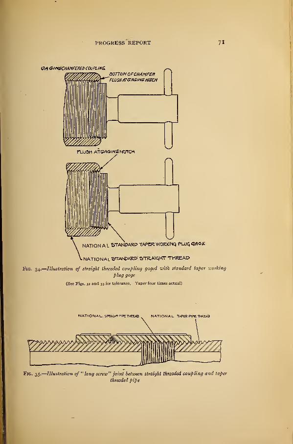
PROGRESS REPORT 71
OA G/rtGCHAMFERED COUPLING. ^BOTTOM OFCHAMFER~Fl USHATGr/IG//i6H07C/1
NATION A L 5TANDARP TAPER WORKING PUJQ<JflOE
. NATIONAL STTANPAKP ffTR.AtQKT THREAD
Fig. 34.
—
lustration of straight threaded coupling gaged with standard taper working
plug gage
(See Figs. 32 and 33 for tolerance. Taper four times actual)
Fig. 35.
—
Illustration of " long screw" joint between straight threaded coupling and taper
threaded pipe
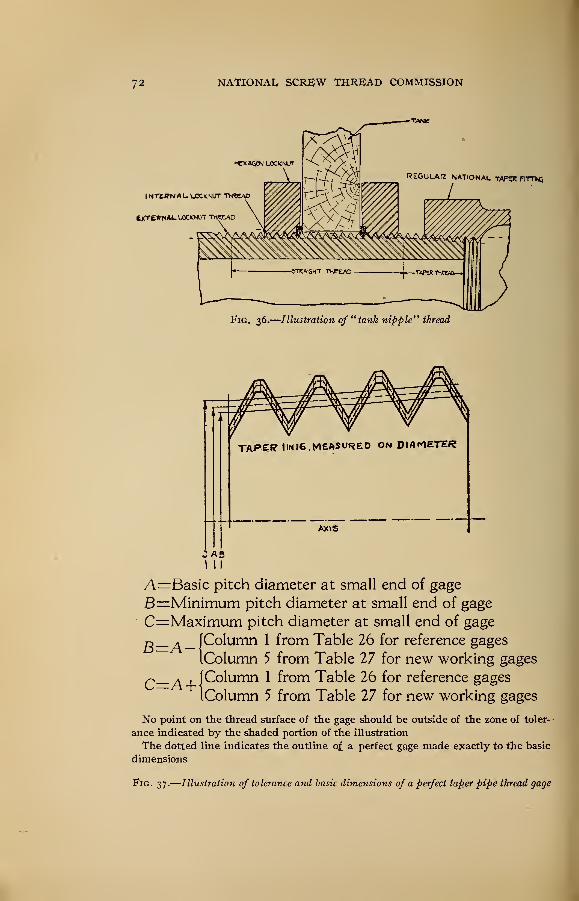
72 NATIONAL, SCREW THREAD COMMISSION
Fig. 36.
—
Illustration of " tank nipple" thread
TAPEff UN 16. MEASURED ON DIAMETER
AXIS
A0I I I
A
—
Basic pitch diameter at small end of gage
B=Minimum pitch diameter at small end of gage
C=Maximum pitch diameter at small end of gage
(Column 1 from Table 26 for reference gages
IColumn 5 from Table 27 for new working gages
[Column 1 from Table 26 for reference gages
IColumn 5 from Table 27 for new working gages
No point on the thread surface of the gage should be outside of the zone of toler- •
ance indicated by the shaded portion of the illustration
The dotted line indicates the outline of. a perfect gage made exactly to the basic
dimensions
Fig. 37.
—
Illustration of tolerance and basic dimensions of a perfect taper pipe thread gage
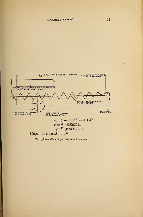
PROGRESS REPORT 73
A=D-(0.05D) + 1.1)P
B=A+ 0.0625UL2=P (0.8D+6.8)
Depth of thread=0.8P
Fig. 38.
—
National taper pipe thread notation
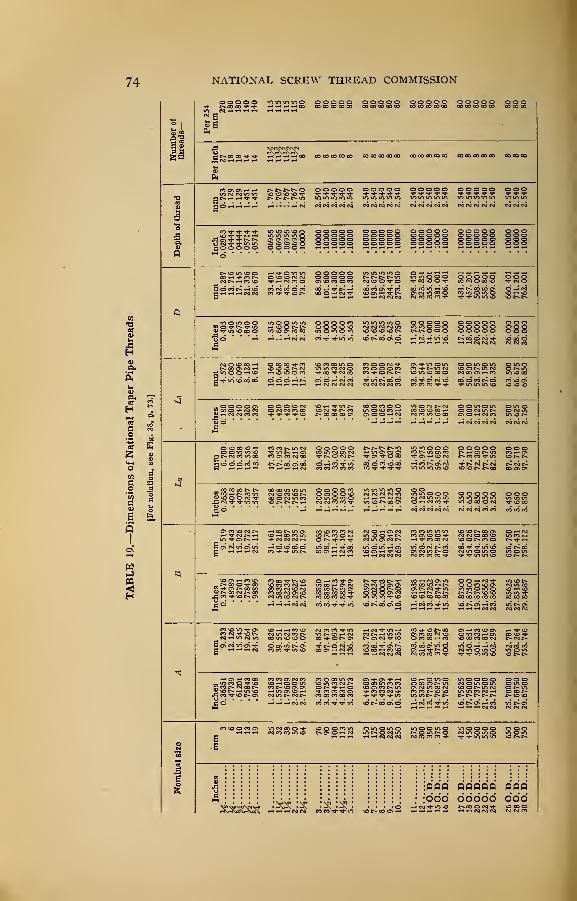
NATIONAL SCREW THREAD COMMISSION
a
Per
254
mm
270 180 180 140 140 2223 s sssss
1
00 00 CO 00 00 0OOO0O0O0O CO CO CO CO OO CO CO CO CO 00
thread
gg§§ss 2.540 2.540 2.540 2.540 2.540 lllllNNNNN NtsicviN^ NNNoiN
2.540 2.540 2.540
o
aa.o •silill ill lllil IIIII IIIII lllll HI
mm
10.287 13.716 17.145 21.336 26.670
=2^11SSSSS
88.900101.600 114.300
127.
000
141.300
ssSSl sssll sills Is!issss mm mm m
Inches
0.405.540 .675 .840
1.050 1.315 1.660 1.900 2.375 2.875 3.500 4.000 4.500 5.000 5.563 ssssg gglli §§§§§--"-2 d^SSS SSSSS
26.000 28.000
30.
000
•J
mm
4.572 5.080 6.096 8.128 8.611
10.
160
10.
668
10.
668
11.074 17.323 19.456 20.853 21.438 22.225 23.800lllls sssss SISSSsssss stssqjs sssss 63.
500
66.
675
69.850
Inches
0.180.200 .240 .320 .339 ailSg slsss !§~ss
^^^^^ «<sj^rj^2.500 2.625 2.750
mm6.
700
,
10.206
10.
358
13.
556
13.861
17.
343
17.953 18.377 19.215
28.
892
30.480 31.750 33.020
34.
290
35.
720 Sslss gillsSSSSS SSSSS sssss
sSISSS;
min mis lllll lllll l§§ss sisls ssg
mm
9.51912.443 15.926
19.
772
25.117lg?2~ slgSS §§§13 Illli gsS
**m mm mm mm mInches
0.37476
.48989 .62701 .77843 .98886
1.
23863
1.58338 1.82234 2.29627 2.76216 3.38850 3.88881 4.38713
4.
88594
5.44929
6.
50597
7.
50234
8.
50003
9.
49797
10.
62094
11.61938 12.61781 13.87262 14.87419
15.
87575
16.87500 17.87500 19.87031 21.86562 23.86094
25.
85625
27.85156
29.
84687
mm
9.23312.126
15.
545
19.264 24.579
30.
826
39.551 45.621 57.633
69.
076 SSiss ggsSS ssiSl sssss ess**m mm mm mm »
iiiii mil mil wm inn mm---riri «oci*™ vo^o S52~S 25.
70000
27.
68750
29.
67500
oN*s
"»°222aa
S38S3 gg|2S §21as alls! sssss Igg
Nomina m >
'
o
&''<•'•'•
« S« cvi n
: : : : : : : i i i iiiiij i j
QBO QQQOQ: : : : :
• [666 66666V^COolS «S°NN 26
O.D
28O.
D
30
O.D
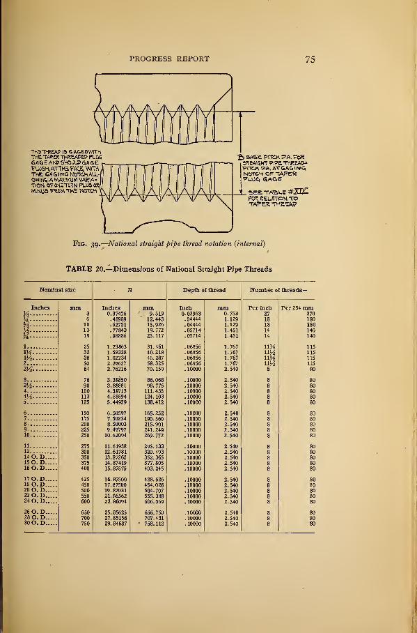
PROGRESS REPORT 75
THIS THREAP IS C.AGEDWITHTHE TAPER THREAPEP PL05GAGE ANP SHOULD <SA GEFU)5H,ATTHE FACE, WITHTHE GAGING NOTCH ALL-tmUSt A MAXIMUM VARIA-TION OFONETURN PLUS ORMINUS FROM THE NOTCH
ba-sc pitch pia. fcRstraight pipe threap*P\TCtt PIA. ATGAGINGN«TCH OF TAPERFL.OG GAGE
SEE TABLE #£ULFOR RELATION TOTAPER. THREAP
Fig. 39.
—
National straight pipe thread notation (internal)0'
TABLE 20.—Dimensions of National Straight Pipe Threads
B Depth of thread Number of threads—
1 Inches mm Inch mm Per inch Per 254 mm3 0.37476 9.519 0. 02963 0.753 27 2706 .48989 12.443 . 04444 1.129 18 180
10 .62701 15.926 . 04444 1.129 18 18013 . 77843 19.772 . 05714 1.451 14 14019 .98886 25.117 .05714 1.451 14 140
25 1.23863 31.461 . 06956 1.767 ny2 11532 1.58338 40.218 .06956 1.767 uy2 11538 1.82234 46. 287 . 06956 1.767 uy2 11550 2.29627 58.325 .06956 1.767 uy2 11564 2. 76216 70. 159 . 10000 2.540 8 80
76 3. 38850 86. 068 . 10000 2.540 8 8090 3.88881 98. 776 . 10000 2.540 8 80
100 4.38713 111.433 . 10000 2.540 8 80113 4. 88594 124.103 . 10000 2.540 8 80125 5. 44929 138.412 . 10000 2.540 8 80
150 6.50597 165. 252 . 10000 2.540 8 80175 7. 50234 190.560 . 10000 2.540 8 80200 8. 50003 215.901 . 10000 2.540 8 80225 9. 49797 241.249 . 10000 2.540 8 80250 10.62094 269. 772 . 10000 2.540 8 80
275 11.61938 295. 133 . 10000 2.540 8 80300 12.61781 320. 493 . 10000 2.540 8 80350 13.87262 352. 365 . 10000 2.540 8 80375 14.87419 377. 805 . 10000 2.540 8 80400 15.87575 403. 245 . 10000 2.540 8 80
425 16. 87500 428. 626 . 10000 2.540 8 80450 17.87500 454. 026 . 10000 2.540 8 80500 19. 87031 504. 707 . 10000 2.540 8 80550 21.86562 555. 388 . 10000 2.540 8 80600 23. 86094 606. 069 . 10000 2.540 8 80
650 25. 85625 656. 750 .10000 2.540 8 80700 27.85156 707.431 . 10000 2.540 8 80750 29.84687 ' 758. 112 . 10000 2.540 8 80
Nominal size
InchesaH%y2m1
1MHi2
2Yi.
33^4
4H5
678910
111214 O. D..15 O. T>._
16 O.D..
17 O. D._I8O.D..20 O. D..22 O. D..24 O. D..
26 O. D..28 O. D..30 O. D..
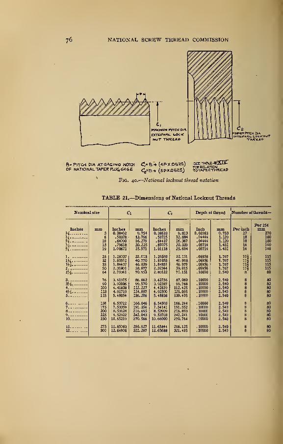
76
B.PITCH DIA ATGAG/NG NOTCH C,=B4 (4PX06^5) ^T^4tjESrOF NATIONAL TAPER PUK,G*<i£ Ce=B+ (SPXJ36eS) T^Af-EKTTrtKEAP
Fig. 40.
—
National locknut thread notation
TABLE 21.—Dimensions of National Locknut Threads
Nominal size Ci C, Depth of thread Number of threads—
Per 254Inches mm Inches mm Inches mm Inch mm Per inch mm
Ys 3 38402 9. 754 38633 9 813 0.02963 0.753 27 270
M ----- 6 50378 12 796 50725 12 884 .04444 1.129 18 180
% 10 64090 16 279 64437 16 367 .04444 1.129 18 180
H 13 79628 20 225 80075 20 339 .05714 1.451 14 140
% 19 1 00672 25 571 1 01118 25 684 . 05714 1.451 14 140
1 25 1 26037 32 013 1 26580. 32 151 . 06956 1.767 Hi 115
Hi 32 1 60512 40 770 1 61055 40 908 .06956 1.767 iii 115m 38 1 84407 46 839 1 84951 46 978 .06956 1.767 11* 115
2 50 2 31801 58 877 2 32344 59 015 .06956 1.767 11J 115
Ztt. 64 2 79341 70 953 2 80122 71 151 . 10000 2.540 8 80
3 76 3 41975 86 862 3 42756 87 060 .10000 2.540 8 80
3y2 90 3 92006 99 570 3 92787 99 768 . 10000 2.540 8 804 100 4 41838 112 227 4 42619 112 425 . 10000 2.540 8 80
113 4 91719 124 897 4 92500 125 095 . 10000 2.540 8 805 125 5 48054 139. 206 5 48836 139 405 . 10000 2.540 8 80
6 150 6 53722 166 046 6 54503 166 244 . 10000 2.540 8 807 175 7 53359 191 354 7 54141 191 552 . 10000 2.540 8 808 200 8 53128 216 695 8 53909 216 893 . 10000 2.540 8 809 225 9 52922 242 043 9 53703 242 241 . 10000 2.540 8 8010 250 10 65219 270 566 10 66000 270 764 . 10000 2.540 8 80
11 275 11 65063 295 927 11 65844 296 125 . 10000 2.540 8 8012 300 12 64906 321. 287 12 65688 321. 485 . 10000 2.540 8 80
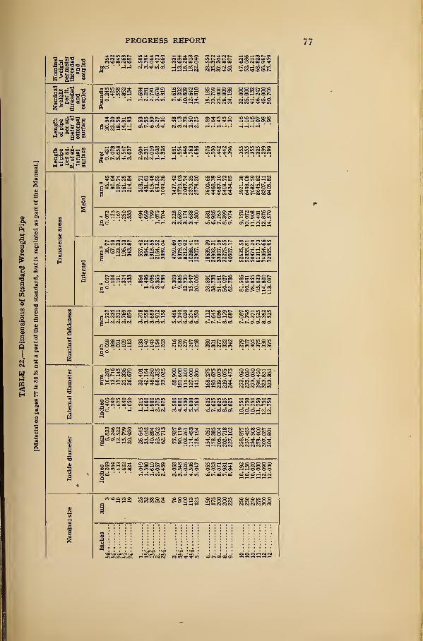
PROGRESS REPORT 77
MM kg
0.364.632 .845
1.268 1.687 2.506 3.394 4.064 5.473 8.660
Nominal weight per
it.
threaded and coupled Pounds
0.245.425 .558 .852
1.134 1.684 2.281 2.731 3.678 5.819 sllsg Siifi ilssll-«SJ3S ssssss
liiim
30.94 23.20 18.56 14.91 11.939.53 7.55 6.59 5.27 4.36 HHHHH
Length
oi
pipe
per
sq.
ft.
of
ex-
ternal surfaceFeet
9.431 7.073 5.658 4.547 3.637 SS§§3N C4 r4 iH
i
mm
3 46.4580.
64
107.74 161.29 214.84
SSSSS SmSSoo
*m iiiii iiiii torn
Ila
20.072
.125 .167 .250 .333 .494 .669 .7991.075 1.704 2.228 2.680 3.174 3.688 4.300 5.581 6.926 7.265 8.399 9.974 9.178
10.072 11.908 13.401 12.876 14.579
iH
Trim
2 36.77 67.10123.23 196.13 343.87 557.42 964.52
1313.55 2164.52 3089.04
4769.
69
6378.08 8212.92
10288.41
12907.
12
18639.39
24992.
31
33007.
16
32275.
55
40507.
17
52635.
58
52058.81
50874.
29
61311.73 74064.66
72965.
95
I
In»
0.057.104 .191 .304 .533 .864
1.495 2.036 3.355 4.78881.585 80.691
78.
855
95.033114.800
113.
097
thicknessmm
1.727 2.235 2.311 2.769 2.870 3.378 3.556 3.683 3.912 5.156 5.486 5.740 6.020 6.274 6.553 7.112 7.645 7.036 8.179 8.687 7.087 7.798 9.271 9.525 8.382 9.525
«5BO
diameter mm
10.287 13.716
17.
145
21.336 26.670 88.900101.600 114.300 127.000 141.300 168.275 193.675 219.075 219.075 244.475
273.
050
273.050
273.
050
298.
450
323.851
323.
851
External
Inches
0.405.540 .675 .840
1.050 1.315 1.660 1.900 2.375 2.875 3.500 4.000 4.500 5.000 5.563 6.625 7.625 8.625 8.625 9.62510.750
10.
750
10.
750
11.750 12.750 12.750
Inside
diameter
•
mm
6.833 9.24612.522 15.799 20.930 26.645 35.052
40.
894
52.
502
62.713aSUSs Sslgs Skills^13* sgsss sssgsg
Inches
0.269.364 .493 .622 .824
1.049 1.380 1.610 2.067 2.469 3.068 3.548 4.026 4.506 5.047 6.065 7.023 8.071 7.981 8.941
10.
192
10.136 10.020 11.000 12.090 12.000
il
size
Nomin;
ijljjjixs is
VO c-^ CO oo o\
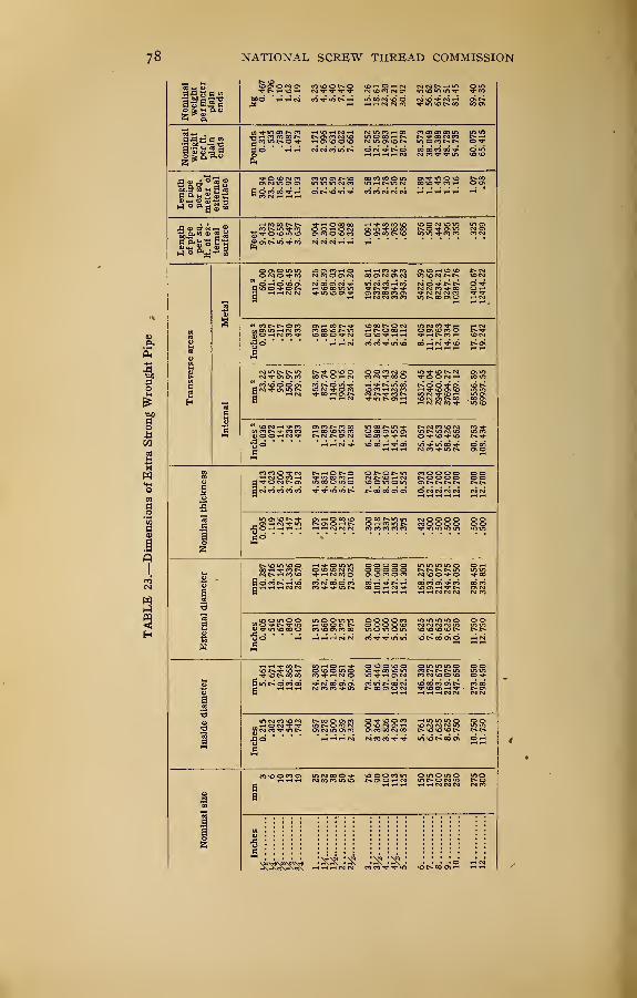
NATIONAL, SCREW THREAD COMMISSION
m §g!SS2 S3£?$? SSSSS §8»d «*«5^ SSSKS
Nominal weight
per
ft.
plainends
Length
of
pipe
per
sq.
meter
of
external surface m30.94 23.20 18.56 14.92 11.93
9.53 7.55 6.59 5.27 4.36 3.58 3.13 2.78 2.50 2.25 1189 1.64 1.45 1.30 1.16 1.07.98
Length
of
pipe
per
sq.
ft.
of
ex- ^SSssS Iss§~ sslsi islsss
!
1
mm
3 60.00101.29 140.00 206.45
279.
35
412.26 568.39 689.03 952.911454.20 1945.81 2372.91
2843.
23
3341.94 3943.23 5422.59 7220.668234.
21
9247.7610387.76
11400.
67
12414.22
Inches
a0.093
.157 .217 .320 .433 .639 .8811.068 1.477 2.254 3.016 3.678 4.407 5.180 6.112 8.405
11.192 12.763 14.334 16.101
17.
671
19.
242
I
mm
2 23.22 46.45 90.97150.97
279.
35
463.
87
827.741140.00 1905.16
2734.
20
4261.30 5734.20 7417.43 9325.8211738.09 16817.45 22240.04
29460.
06
37694.
27
48169.
12
58556.89 69957.55
issSs? ggggg lllss ssi-l|° ™* SSSSS g§
!
I
s2glsS SSISs islss SIIII 11.gcJeimmco r-icooodd d ™ n co <-5 n n
^ISSSa Sslss IsssS stlis §13 d
!
1
ggssg Iiiii ass*!**m am m
s°§sl§ silEs ilsls ssis-g gg•3d
-' 'rJ ^^^N^ m*-*V>lri iN»«d
j-jjj
]
i
SSIIs ills! Sills sSsss 11i-sss *m** mrn-m
»~m%z aSIIS llsls Ssssg ggJad •
- - -
'rtrtrtN N«n«« n»N»o; 03
1
1
—SSS 8885B SKSSS RS
. , . .
"xsfcsis: J3&i$ ^J&i JJJois
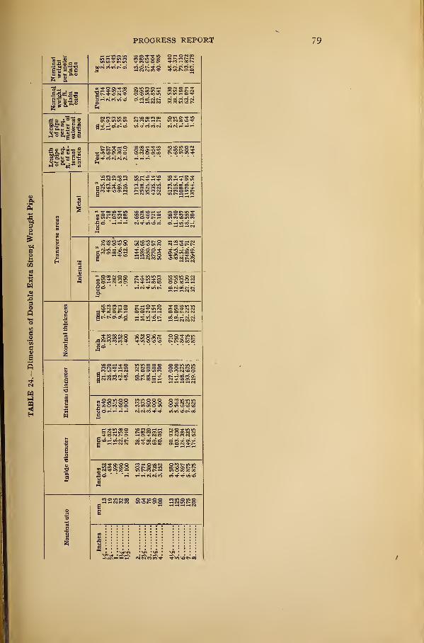
PROGRESS REPORT
Nominalweight
per
meter
plainends
SSsKS §^gga,™™^ doggo ajftggS
IliaPounds
1.714 2.440 3.659
5.
214
6.408 9.02913.695 18.583 22.850 27.541 32.530 38.552
53.
160
63.
079
72.424
Length
of
pipe
per
sq.
meter
of
external surface m14.92 11.93
9.53 7.55 6.59 5.27 4.36 3.58 3.
132.78 2.50 2.25 1.89 1.64 1.45
Length
of
pipe
per
sq.
ft.
of
ex-
ternal surface Feet
4.547 3.637 2.904
2.
301
2.010
•
1.608 1.328 1.091.954 .848 .763 .686 .576 .500 .442
!
Metal
mm
2325.16 463.23
694.
19
989.
68
1713.55 2598.71 3526.46 4336.14 5226.46 6173.56 7316.14
10088.41 11970.99
13744.
54
sSsisi bIIss slSSI
Internal
mm
2 32.26 95.48 181.93"
406.45 612.901144.52 1589.68
2680.
65
3770.97
5034.
20
6494.21
8365.
18
12151.64 17489.71
23949.
72
i
Bliggl S§IS§l^«»s ™ss sa'sas
i
i
mm
21.336 26.670 33.401
42.
164
48.260 60.325 73.025 88.900101.600 114.300 127.000 141.300 168.275
193.
675
219.075
s!§3§§ issss
i
!
isasl Silas sll-sj-SjWWSi S?SS§ gSS?S
SS5Sl§ igfgs £§§§§
Nominal
size
22SSS sssssa
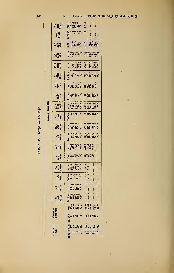
NATIONAL SCREW THREAD COMMISSION
11JSSSSS 2 : : :
Ill
41 JIBS hh
*n pPfl mill
m O T}- 00 Cs3 v£) ^-NOOOIO*
41 jlifif mill
so
311
S 41
511 lum mm41 mm mmSl|
41
=11 mm339.7 365.1 390.5 415.9 441.3 492.0 542.9
41 |sn iii
i
si!oi w h ui ! !
'.
;
litisi MM
41 jjjj
imm mmi!
1' |S!22S2 SSSSSg
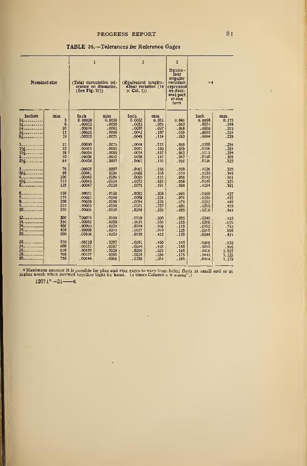
PROGRESS REPORT 8
1
TABLE 26.—Tolerances for Reference Gages
Nominal size
1
(Total cumulative tol-
erance on diameter.(See Fig. 37))
2
(Equivalent longitu-dinal variation (16
X Col. 1))
3
L. 4 Ul Vd —
lentaii£ uiai
variation
expressedQ c don".
lllal pall
turn*
a4
Inches mm Inch mm Inch mm Inch mmVs 3 0. 00020 0. 0050 0. 0032 0.081 0. 086 0. 0068 0. 173
M 6 . 00022 .0056 .0035 .089 .063 .0074 .18810 00024 0061 0038 . 097 .068 . 0080 . 203
y>&
13 .00026 !0066 !o042 .107 .059 .0088 .22419 . 00028 .0071 .0045 .114 .063 .0094 .239
i 25 . 00030 .0076 .0048 .122 .055 .0100 .254IX 32 . 00032 .0081 .0051 .130 . 059 .0106 .269m 38 . 00034 .0086 .0054 .137 . 062 .0112 .284
50 . 00036 . 0091 . 0058 . 147 .067 .0120 .305zy2 64 . 00038 .0097 .0061 .155 .050 .0126 .320
3 76 . 00038 .0097 .0061 .155 .050 .0126 .320
3M 90 .00041 0104 .0066 .168 .053 .0136 .3454 100 . 00043 .0109 .0069 .175 .055 .0142 .3614*2 113 . 00045 .0114 .0072 .183 .058 .0148 .3765 125 . 00047 .0119 .0075 .191 .060 .0154 .391
6 150 . 00051 .0130 .0082 .208 . 065 .0168 .4277 175 . 00055 .0140 .0088 .224 .070 .0180 .4578 200 . 00059 .0150 .0094 .239 .075 .0192 .4889 225 . 00063 .0160 .0101 .257 .080 .0206 .52310 250 .00066 .0168 .0106 .269 . 085 .0216 .549
12 300 ! 00074 .0188 .0118 .300 .095 .0240 .61014 350 . 00082 .0208 .0131 .333 .105 .0266 .67616 400 . 00090 .0229 .0144 .366 .115 .0292 .74218 450 . 00098 .0249 .0157 .399 .125 .0318 .80820 500 .00106 .0269 .0170 .432 .135 .0344 .874
22 550 .00113 .0287 .0181 .460 .145 .0366 .93024 600 .00121 .0307 .0194 .493 .155 .0392 .99626 650 .00129 .0328 .0206 .523 .165 .0416 1.05728 700 .00137 .0348 .0219 .556 .175 .0442 1.12330 750 .00144 .0366 .0230 .584 .185 .0464 1.179
a Maximum amount it is possible for plug and ring gages to vary from being flush at small end or atgaging notch when screwed together tight by hand. (2 times Column 2 + 0.0004".)
12071°—21 6
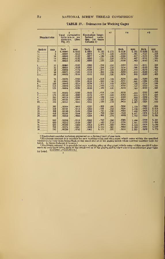
82 NATIONAL, SCREW THREAD COMMISSION
TABLE 27.—Tolerances for Working Gages
Nominal size
5
Total cumulativetolerance ondiameter. (SeeFi?. 37)
6Equivalent longi-tudinal varia-tion. (16 timesColumn 5)
«7 68 c9
Inches mm Inch mm Inch mm Inch mm Inch mmyi 3 0. 00040 0. 0102 0. 0064 0.163 0. 172 0. 0138 0. 351 0. 0103 0.262
>4 6 . 00044 .0112 .0070 .178 . 126 .0150 .381 .0112 .284
Pi 10 . 00048 .0122 .0077 .196 . 136 .0164 .417 .0122 .310
Yj 13 . 00052 . 0132 . 0083 . 211 . 118 . 0176 • 447 . jjj
19 . 00056 .0142 .0090 .229 . 126 .0190 .483 !0142 .361
1 25 . 00060 .0152 .0096 .244 . 110 .0202 .513 .0151 .384
32 . 00064 .0163 . 0102 .259 . 118 .0214 .544 .0160 .406
V4 38 . 00068 .0173 .0109 .277 . 124 .0228 .579 . 0170 .432
2..'. 50 . 00072 . 0183 . 0115 292 . 134 . 610 0180 tOt
Z TA 64 . 00076 .0193 .0122 310 . 100 !0254 .645 !oi90 .483
3 76 . 00076 .0193 .0122 .310 . 100 .0254 .645 .0190 .483
90 . 00082 .0208 .0131 .333 . 105 .0272 .691 .0204 .518
4 100 . 00086 .0218 .0138 .351 . 110 .0286 .726 .0214 .544
4H 113 . 00090 .0229 .0144 .366 . 115 .0298 .757 .0223 .566
5 125 . 00094 . 0239 . 0150 . 381 . 120 . 0310 .787 . 0232 . 589
6 150 . 00102 .0260 .0163 .414 . 130 .0336 .853 .0252 .640
7..: 175 . 00110 .0330 .0176 .447 . 140 .0362 .919 .0271 .688
8... 200 . 00118 .0348 .0189 .480 . 150 .0388 .986 .0290 .737
9 225 . 00126 .0370 .0202 .513 . 160 .0414 1. 052 .0310 .787
10 250 . 00132 .0432 .0211 . 536 .170 .0432 1. 097 .0324 .823
12 300 . 00148 .0472 .0237 .602 .190 .0484 1. 229 .0362 .919
14 350 . 00164 .0513 .0262 .665 .210 .0534 1. 356 .0400 1. 016
16 400 . 00180 .0554 . 0288 .732 .230 .0586 1. 488 .0439. 1. 115
18 450 . 00196 .0594 .0314 .798 .250 .0638 1. 621 .0478 1. 214
20 500 . 00212 .0683 . 0339 .861 .270 .0688 1.748 .0516 1. 311
22 550 . 00226 .0719 .0362 .919 .290 .0364 1. 864 .0550 1.397
24 600 . 00242 .0759 .0387 .983 .310 .0784 1.991 .0588 1.494
26 650 . 00258 .0800 .0413 1.049 .330 .0836 2. 123 .0626 1.590
28 700 . 00274 .0841 .0438 1.113 .350 .0886 2. 250 .0664 1. 687
30 750 . 00288 .0732 .0461 1. 171 .370 .0932 2. 367 .0698 1.773
a Equivalent angular variation expressed as a decimal part of one turn.Maximum amount it is possible for new working plug and ring gages which come within the specified
tolerances to vary from being flush at the small end or at the gaging notch when screwed together tight byhand. (2 times Column 6+0.0010.)
cMaximum amount it is possible for new working plug or ring gages which come within specified toler-ances to vary from being flush at the small end or at the gaging notch when screwed on reference gage tight... (Column 4+Column 8.)
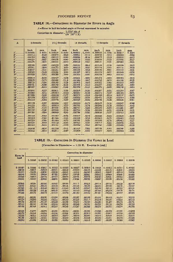
PROGRESS REPORT 83
TABLE 28.—Corrections in Diameter for Errors in Angle
A= Error in half included angle of thread expressed in minutes
x. . 1.332P sin ACorrection in diameter= 1
—
j^-z—T .
sm (60+^4)
A 8 threads WV2 threads 14 threads IS threads 27 threads
Inch mm Inch mm Inch mm Inch mm Inch mm0. 000056 0.0014 0. 000039 0.0010 0. 000032 0. 0008 0. 000025 0.0006 0.000017 0. 0004
. 000112 .0028 . 000078 . 0020 . 000064 . 0016 . 000050 .0013 . 000033 . 0008
. 000168 . 0043 . 000117 . 0030 OOOOQfi. 0024 00007^ 0019 nooo^o 0013
. 000224 . 0057 . 000156 . 0040 . 000128 . 0033 0000QQ . 0025 OOOOfifi 00175'
. 000279 . 0071 . 000194 . 0049 0001 fiO . 0041 0001 74 . 0031 000083. UUUU03 . 0021
c/. 000335 .0085 . 000233 .0059 . 000192 .0049 .000149 .0038 . 000099 .0025
7'. 000391 . 0099 . 000272 . 0069 . 000223 .0057 .000174 . 0044 . 000116 .0029
g/. 000447 . 0114 . 0079 nnn?^ 0065 000199 0051 nnm
. UUU LOL, 00349'
. 000503 .0128 . 000350 . 0089 . 0073 • \J\J\JC1C1O . 0057 . 000149 003810'
. 000558 . 0142 . 000388 . 0099 . 0081 . 0063 . 0042
.000614 .0156 . 000427 .0108 . 000351 .0089 .000273 .0069 . 000182 .004612' . 000670 . 0170 . 000466 . 0118 . 000383 .0097 . 000298 .0076 . 000198 .00501 Q' 0007?5 . 0184 000^0^ . 0128 . UUUTl J 0105 nnn^??. \J\J\JOLiU 0082 nnn?i
^
0055It ...... . 000781 '. 0198 . 000543 !oi38 . 000446 !0113 . 000347 !0088 . 000231 !005915' • UUUoo/ 0213 0148 . UUUt" / . UUUO
/
u . 0095 . UUU£*fo . 0063
. 000892 .0227 . 000621 .0158 .000510 .0130 . 000397 .0101 . 000264 .006717' . 000948 .0241 . 000660 .0168 . 000542 .0138 .000421 .0107 .000281 .007118' . 001004 .0255 . 000698 .0177 . 000574 .0146 . 000446 .0113 . 000297 .007519' . 001059 .0269 . 000737 .0187 . 000605 .0154 . 000471 .0120 .000314 .008020' .001115 .0283 . 000776 .0197 . 000637 .0162 . 000495 .0126 . 000330 .0084
21' .001170 .0297 . 000814 .0207 . 000669 .0170 . 000520 .0132 . 000347 .008822' . 001226 .0311 . 000853 .0217 . 000700 .0178 . 000545 .0138 . 000363 .009223' .001281 .0325 . 000891 .0226 . 000732 .0186 . 000570 .0145 . 000380 .009724' . 001337 .0340 . 000930 .0236 . 000764 .0194 . 000594 .0151 . 000396 .010125' . 001392 .0354 . 000969 .0246 . 000796 .0202 .000619 .0157 .000413 .0105
26' .001448 .0368 . 001007 .0256 . 000827 .0210 . 000643 .0163 . 000429 .010927' . 001503 .0382 . 001046 .0266 . 000859 .0218 . 000668 .0170 . 000445 .011328' . 001559 .0396 . 001084 .0275 . 000891 .0226 . 000693 .0176 . 000462 .011729' .001614 .0410 .001123 .0285 .000922 .0234 .000717 .0182 . 000478 .012130' .001669 .0424 .001161 .0295 .000954 .0242 . 000742 .0188 . 000495 .0126
45' . 002498 .0634 .001738 .0441 . 001427 .0362 .001110 .0282 . 000740 .018860' . 003322 .0844 .002311 .0587 .001899 .0482 . 001477 .0375 . 000984 .0250
TABLE 29.—Correction in Diameter For Errors in Lead
[Correction in Diameter= — 1.732 E. E=error in lead.]
Correction in diameter
lead0. 00000 0. 00001 0. 00002 0. 00003 0. 00004 0. 00005 0. 00006 0. 00007 0. 00008 0. 00009
0. 00000 0. 00000 0. 00002 0. 00003 0. 00005 0. 00007 0. 00009 0. 00010 0.00012 0.00014 0. 00016.00010 .00017 . 00019 . 00021 . 00023 . 00024 . 00026 . 00028 . 00029 . 00031 . 00033. 00020 . 00035 . 00036 .00038 . 00040 . 00042 . 00043 . 00045 . 00047 . 00048 . 00050. 00030 . 00052 . 00054 . 00055 . 00057 . 00059 . 00061 . 00062 . 00064 . 00066 . 00068.00040 . 00069 . 00071 . 00073 . 00074 . 00076 . 00078 .00080 . 00081 . 00083 . 00085. 00050 .'. 00087 . 00088 . 00090 . 00092 . 00094 . 00095 . 00097 .00099 . 00100 . 00102
. 00060 . 00104 .00106 .00107 . 00109 .00111 .00113 .00114 .00116 .00118 . 00120
. 00070 .00121 . 00123 .00125 .00126 .00128 .00130 . 00132 . 00133 . 00135 .00137
. 00080 .00139 .00140 .00142 .00144 .00145 .00147 .00149 .00151 .00152 .00154
. 00090 .00156 .00158 .00159 .00161 . 00163 .00165 .00166 .00168 . 00170 .00171
. 00100 .00173 .00175 . 00177 .00178 .00180 .00182 .00184 .00185 .00187 . 00189
.00110 .00191 .00192 . 00194 . 00196 . 00197 . 00199 .00201 . 00203 . 00204 . 00206
.00120 . 00208 .00210 .00211 .00213 . 00215 .00217 .00218 . 00220 .00222 .00223
.00130 .00225 . 00227 . 00229 . 00230 . 00232 .00234 . 00236 00237 .00239 . 00241
.00140 .00242 . 00244 .00246 . 00248 . 00249 .00251 . 00253 . 00255 . 00256 . 00258
.00150 .00260 .00262 . 00263 . 00265 . 00267 . 00268 . 00270 . 00272 .00274 . 00275
. 00160 . 00277 . 00279 . 00281 . 00282 . 00284 . 00286 . 00288 . 00289 . 00291 . 00293
. 00170 . 00294 . 00296 . 00298 . 00300 . 00301 . 00303 . 00305 . 00307 . 00308 .00310
.00180 . 00312 .00313 .00315 . 00317 . 00319 . 00340 . 00322 .00324 .00326 . 00327
.00190 . 00329 . 00331 . 00333 . 00334 . 00336 . 00338 . 00339 . 00341 . 00343 .00345
. 00200 . 00346 . 00348 . 00350 . 00352 .00353 . 00355 . 00357 . 00359 . 00360 . 00362
84 NATIONAL SCREW THREAD COMMISSION
VIII. FUTURE WORK OF COMMISSION
The problems of standardization so far considered by the com-
mission have been those of most pressing importance to manufac-
turers and users of screw-thread products. Problems of less im-
portance have necessarily been postponed until such time as they
can be given proper consideration.
It is the intention of the commission, after issuing the present
tentative report, to continue the work of gathering information
in regard to special problems still to be considered. In this con-
nection, there is outlined in the following paragraphs some of the
standardization work that should be done.
1. THREADS REQUIRING STANDARDIZATION
The following list includes the more important screw threads
which require standardization
:
(a) Threads cut on brass tubing.
(b) Instrument threads.
(c) Acme, square, buttress, and other special threads.
2. STANDARDIZATION OF PRODUCTS CLOSELY ALLIED TO THE MANU-FACTURE OF SCREW THREADS
In addition to the standardization of various thread systems, it
would be of great advantage to American manufacturers to have
established standards for stock tools and other appliances used in
the production of screw threads, such as are mentioned in the fol-
lowing list:
(a) Taps.
(b) Dies.
(c) Sizes of bar stock for producing cut threads.
(d) Sizes of bar stock for producing rolled threads.
(e) Dimensions of bolt heads and nuts.
(/) Standardization of sheet-metal and wire-gage sizes.
(g) Standardization of tap-drill sizes.
3. POSSIBILITY OF INTERNATIONAL STANDARDIZATION
The recent war has demonstrated the need of interchangeability
of articles manufactured in this country with those manufactured
in foreign countries, and it is known that manufacturers andauthorities of Great Britain, France, and other foreign countries
are awake to the situation and, in fact, have already taken steps
toward the international standardization of screw threads and
PROGRESS REPORT 85
other manufactured articles. Furthermore, international stand-
ardization is of great importance in connection with the develop-
ment of foreign trade.
In July, 1919, the commission sent to Europe a delegation of
its members to confer with British and French engineering stand-
ards organizations, and while no definite agreements were
reached in regard to international standardization of screw
threads, it was apparent in both France and England that the
engineers and manufacturers in these countries are anxious to
cooperate with the United States in this work. The time is very
opportune for accomplishments along this line, and it is the opin-
ion of the commission that, as a result of the war, it should be pos-
sible to reach an agreement on an international standard thread.
Such an international standard should be established by giving
consideration to the predominating sizes and standards used in
manufactured products, as well as to the possibilities of providing
a means for producing this international screw thread by the use
of either the English or the metric system of measurement.
S. W. Stratton,(Director, Bureau of Standards)
Chairman, National Screw Thread Commission.
Washington, June 26, 1920.
IX. APPENDIXES
APPENDIX 1. ORIGIN OF THE COMMISSION
(a) Historical.—The standardization of screw threads has been a subject of vital
interest to manufacturers since the efforts of Sir Joseph Whitworth in 1841 and of
William Sellers in 1864. The efforts of Sir Joseph Whitworth in ascertaining shop
practice in the manufacture of screw threads resulted in the standardization and adop-
tion of the Whitworth Thread System, which found extensive use in England. WhenWilliam Sellers promulgated through the Franklin Institute the Sellers Thread,
which resulted in the extensive use of the present United States Standard series, a
great achievement of direct benefit to American manufacturers was realized.
In recent years numerous organizations have carried forward the standardization of
screw threads. The American Society of Mechanical Engineers, the Society of Auto-
motive Engineers, the Bureau of Standards, and prominent manufacturers of special-
ized thread products, have been the chief influences in standardization of screw threads
in this country. In England the standardization of screw threads has been carried
forward by the British Engineering Standards Association, an organization formed in
1001.
The development in the manufacture of machine tools, automobiles, agricultural
implements, typewriters, sewing machines, and other standard manufacturing pro-
ducts has made apparent the need for standardized and interchangeable screw threads
and threaded parts. In addition to the need of standardization, which grew by virtue
of improvements in general manufacturing practices, the difficulties encountered in
the program for procuring munitions in the recent war demonstrated the vital neces-
sity of standardized screw threads. Through the efforts of the engineering societies,
the Bureau of Standards, and prominent manufacturers of screw-thread products
a petition was presented to Congress, requesting the appointment of a commission to
investigate and promulgate standards of screw threads to be adopted by manufactur-
ing plants under the control of the Army and Navy, and for adoption and use by the
public.
(6) Commission Authorized by Congress.—As a result of this action, the National
Screw Thread Commission was authorized by the following act of Congress, approved
July 18, 1918. (Public Document No. 201, 65th Cong., H. R. 10852.)
AN ACT To provide for the appointment of a commission to standardize screw threads.
Be it enacted by the Senate and House ofRepresentatives of the United States ofAmerica in Congress assembled,
That a commission is hereby created, to be known as the Commission for the Standardization of Screw
Threads, hereinafter referred to as the commission, which shall be composed of nine commissioners, one
of whom shall be the Director of the Bureau of Standards, who shall be chairman of the commission ; twocommissioned officers of the Army, to be appointed by the Secretary of War; two commissioned officers of
the Navy, to be appointed by the Secretary of the Navy; and four to be appointed by the Secretary of Com-merce, two of whom shall be chosen from nominations made by. the American Society of Mechanical Engi-
neers and two from nominations made by the Society of Automotive Engineers.
Sec. 2. That it shall be the duty of said commission to ascertain and establish standards for screw threads,
which shall be submitted to the Secretary of War, the Secretary of the Navy, and the Secretary of Commercefor their acceptance and approval. Such standards, when thus accepted and approved, shall be adopted
and used in the several manufacturing plants under the control of the War and Navy Departments, and,
so far as practicable, in all specifications for screw threads in proposals for manufactured articles, parts, or
materials to be used under the direction of these departments. -*
Sec. 3. That the Secretary of Commerce shall promulgate such standards for use by the public and cause
the same to be published as a public document.
Sec. 4. That the commission shall serve without compensation, but nothing herein shall be held to affect
the pay of the commissioners appointed from the Army and Navy or of the Director of the Bureau of Stand-
ards.
86
PROGRESS REPORT 87
Sec. 5. That the commission may adopt rules and regulations in regard to its procedure and the conduct
of its business.
Sec. 6. That the commission shall cease and terminate at the end of six months from date the of its ap-
pointment.
Approved, July 18, 1918.
(c) LrFE of Commission Extended by Congress.—Prior to the expiration of the
original term of six months for which the commission was appointed, it became ap-
parent that it would be impossible to complete in a satisfactory manner the work
outlined by the commission. An extension of time was therefore asked by the com-
mission and granted by Congress in accordance with the following act: (Public No.
324, 65th Cong. H. R. 15495.)
AN ACT To amend an Act to provide for the appointment of a commisson to standardize screw threads.
Be it enacted by the Senate and House of Representatives of the United States ofA merica in Congress assembled.
That the Act providing for the appointment of a commission to standardize screw threads, approved July
eighteenth, nineteen hundred and eighteen, be, and the same is hereby, amended so that it will read:
"That a commission is hereby created, to be known as the Commission for the Standardization of Screw
Threads, hereinafter referred to as the commission, which shall be composed of nine commissioners; one
of whom shall be the Director of the Bureau of Standards, who shall be chairman of the commission; tworepresentatives of the Army, to be appointed by the Secretary of War; two representatives of the Navy,to be appointed by the Secretary of the Navy; and four to be appointed by the Secretary of Commerce,
two of whom shall be chosen from nominations made by the American Society of Mechanical Engineers
and two from nominations made by the Society of Automotive Engineers.
"Sec. 2. That it shall be the duty of said commission to ascertain and e3tablish standards for screw
threads, which shall be submitted to the Secretary of War, the Secretary of the Navy, and the Secretary
of Commerce for their acceptance and approval. Such standards, when thus accepted and approved, shall
be adopted and used in the several manufacturing plants under the control of the War and Navy Depart-
ments, and, so far as pratcicable, in all specifications for screw threads in proposals for manufactured arti-
cles, parts, or materials to be used under the direction of these departments.
"Sec. 3. That the Secretary of Commerce shall promulgate such standards for use by the public and
cause the same to be published as a public document.
"Sec. 4. That the commission shall serve without compensation, but nothing herein shall be held to
affect the pay of the commissioners appointed from the Army and Navy or of the Director of the Bureau of
Standards.
"Sec. 5. That the commission may adopt rules and regulations in regard to its procedure and the conduct
of its business.
"Sec. 6. That the commission shall cease and terminate at the end of one year and six months from the
date of its original appointment."
Approved, March 3, 1919.
(d) Life of Commission Again Extended by Congress.—Recognizing the im-
possibility of perfecting a report of this character in the first issue, and realizing the
importance of providing an opportunity for making necessary changes, Congress
extended the life of the commission for an additional term of two years by the following
joint resolution: (Public Resolution, No. 34, 66th Cong. H. J. Res. 299.)
JOINT RESOLUTION Extending the term of the National Screw Thread Commission for a period of two
years from March 21, 1920.
Resolved by the Senate and House of Representatives of the United Stales of America in Congress assembled.
That the term of the National Screw Thread Commission, created by an Act approved July iS, 1918, as
amended by an Act approved March 3, 1919, be, and the same is hereby, extended for an additional period
of two years from March 21, 1920.
Approved, March 23, 1920.
APPENDIX 2. ORGANIZATION OF THE COMMISSION
a) Preliminary Meeting.—As soon as nominees were selected by the various
organizations to be represented in the Commission, a preliminary meeting was called
at Washington, D. C, on September 12, 1918, by Dr. S. W. Stratton, Director of the
Bureau of Standards, and chairman of the commission. At this meeting the organi-
zation of the commission was planned in order that work could be started as soon as
formal appointments of the various members of the commission were made. Thevarious commissioners were formally appointed under date of September 21, 1918.
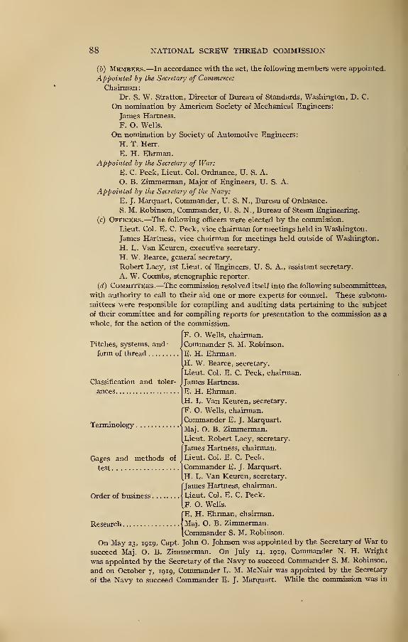
88 NATIONAL SCREW THREAD COMMISSION
(6) MEMBERS.—In accordance with the act, the following members were appointed.
Appointed by the Secretary of Commerce:
Chairman
:
Dr. S. W. Stratton, Director of Bureau of Standards, Washington, D. C.
On nomination by American Society of Mechanical Engineers:
James Hartness.
F. O. Wells.
On nomination by Society of Automotive Engineers:
H. T. Herr.
E. H. Ehrman.
Appointed by the Secretary of War:
E. C. Peck, Lieut. Col. Ordnance, U. S. A.
O. B. Zimmerman, Major of Engineers, U. S. A.
Appointed by the Secretary of the Navy:
E. J. Marquart, Commander, U. S. N., Bureau of Ordnance.
S. M. Robinson, Commander, U. S. N., Bureau of Steam Engineering.
(c) Officers.—The following officers were elected by the commission.
Lieut. Col. E. C. Peck, vice chairman for meetings held in Washington.
James Hartness, vice chairman for meetings held outside of Washington.
H. L. Van Keuren, executive secretary.
H- W. Bearce, general secretary.
Robert Lacy, ist Lieut, of Engineers, U. S. A., assistant secretary.
A. W. Coombs, stenographic reporter.
(d) Committees.—The commission resolved itself into the following subcommittees,
with authority to call to their aid one or more experts for counsel. These subcom-
mittees were responsible for compiling and auditing data pertaining to the subject
of their committee and for compiling reports for presentation to the commission as a
whole, for the action of the commission.
F. O. Wells, chairman.
Commander S. M. Robinson.
E- H. Ehrman.H. W. Bearce, secretary.
Lieut. Col. E. C. Peck, chairman.
James Hartness.
E. H. Ehrman.H. L. Van Keuren, secretary.
IF. O. Wells, chairman.
JCommander E. J. Marquart.
Maj. O. B. Zimmerman.Lieut. Robert Lacy, secretary.
James Hartness, chairman.
Lieut. Col. E. C. Peck.
Commander E- J- Marquart.
H. L. Van Keuren, secretary.
I
James Hartness, chairman.
Lieut. Col. E. C. Peck.
F. O. Wells.
IE.
H. Ehrman, chairman.
Maj. O. B. Zimmerman.
Commander S. M. Robinson.
On May 23, 1919, Capt. John O. Johnson was appointed by the Secretary of War to
succeed Maj. O. B. Zimmerman. On July 14, 1919, Commander N. H. Wright
was appointed by the Secretary of the Navy to succeed Commander S. M. Robinson,
and on October 7, 1919, Commander L. M. McNair was appointed by the Secretary
of the Navy to succeed Commander E. J. Marquart. While the commission was in
Pitches, systems, and-
form of thread
Classification and toler-
ances
Terminology <
.
Gages
test
and methods of
PROGRESS REPORT 89
England and France, the Navy Department was represented by Capt. L. B. McBride.
On May 10, 1920, Commander Joseph S. Evans was appointed by the Secretary of the
Navy to succeed Commander N. H. Wright. On December 15, 1920, Mr. Ralph E.
Flanders was appointed by the Secretary of Commerce, to succeed Mr. James
Hartness.
APPENDIX 3. PROCEDURE OF COMMISSION
(a) General Procedure.—In its work of establishing standards for screw threads
the commission has made particular effort to secure the actual facts concerning the
need of standardization and the economic conditions to be provided for in the pro-
duction and use of screw threads.
The commission has had the advantage of being able to proceed rapidly inasmuch
as in recent years the accomplishments of the American Society of Mechanical Engi-
neers and the Society of Automotive Engineers have paved the waytoward the adoption
of necessary screw-thread standards. Without this preliminary work it would have
been considered impracticable and unnecessary. In addition the results accom-
plished by the British Engineering Standards Committee in their standardization
work have been available to the commission and advantage has been taken of the
accomplishments realized by this organization. Furthermore the commission has
availed itself of the opportunity to secure from such organizations as the Tap Makers
Association and representatives of prominent manufacturing concerns valuable
information and data regarding the production of tools and appliances for making
threaded products, as well as information and data regarding the application and use
of screw-thread products.
(6) Public Hearings.—After the preliminary organization of the commission
immediate steps were taken to secure from various screw-thread authorities and
representative manufacturers and users testimony as to the nature of the National
standards to be adopted for the use of the Government and for American manufacturers.
To secure this information several public hearings were conducted in various indus-
trial centers throughout the country.
Government officials, authorities on screw threads, manufacturers and users of
screw-thread products, as well as manufacturers of taps, dies, gages, and other tools
required for producing screw-thread products, were invited to attend these hearings
and present their views on various phases of the subject. Every effort was made to
have in attendance at these hearings representatives of prominent manufacturers
and organizations interested in standardization work. To this end invitations were
sent to a large mailing list and in addition announcement of the meetings, extending
invitations to be present, were published in the technical magazines. Topic sheets
were distributed in advance of the hearings in order that witnesses could prepare
their views on the subjects of the meeting in a definite, concise, and authentic form.
A large amount of evidence was collected in this way and the opportunity was avail-
able for the various members of the commission to bring out by cross-examination
information which could have been secured in no other way. This evidence was
tabulated for the consideration of the commission in formulating its report.
The following schedule lists the dates of the various hearings:
October 7, igi8
Hearing held in Engineering Societies Building, 29 Vest Thirty-ninth Street, New York City.
Topic—Fastening Screws, questions 1 to 5.
October 21
Hearing held in Engineering Societies Building, 29 West Thirty-ninth Street, New York City.
Topic—Pipe Threads, Brass Tubing, Hose Couplings, Special Threads and Instrument Threads
as outlined in Topic Sheet.
November 8
Hearing held at Bureau of Standards, Washington, D. C. All topics, as outlined in Topic Sheet.
November 11 and 12
Hearing held at Hotel Statler, Detroit, Mich. All topics, as outlined in Topic Sheet.
November 13
Hearing held at Hotel Miami, Dayton, Ohio. All topics, as outlined in Topic Sheet.
go NATIONAL SCREW THREAD COMMISSION
(c) Topic Sheet.—The following topics are those which were discussed at the
various hearings
:
TOPICS FOR DISCUSSION AT HEARINGS OF NATIONAL SCREW THREAD
(z) Fastening Screws.—i. As a national standard, is there any objection to the continuation of the U. S.
Standard System of thread diameters and pitches for general use in practically its present shape?
2. As a national standard, is there any objection to the adoption of the S. A. E. System of diameters
and pitches of fine threads?
3. As a national standard, to what extent could the A. S. M. E. System of standard machine screws
be adopted ?
4. There seems to be a general feeling that in the standardization of fastening screws tolerances andclearances should be provided to cover several grades of work and to allow for several classes of fit ranging
from a stud fit to a very loose fit. Would provision for four classes of fit including the stud fit be sufficient
for all grades of work encountered in screws made to the various systems previously mentioned or should
such a classification include more than four classes?
5. Is there any objection to adopting the "standard hole" practice for screw threads; that is, the practice
of making all the taps for any particular thread of one basic size and securing the required fit by changing
the diameter of the screw or male threaded work which is to assemble with the nut cut by the basic tap?
(2) Pipe Threads.— 1. As a national standard, is there any objection to the adoption of the American
Briggs pipe-thread sizes for both taper and straight pipe threads as accepted by the American Society of
Mechanical Engineers?
2. In view of the experiments on the form of pipe threads conducted by the Pennsylvania Railroad in
connection with the American Society of Testing Materials which tend to show the desirability of the
U. S. Standard form with flat top and bottom one-eighth of the pitch, do you consider it advisable to
adopt the U. S. Standard form instead of the present form which specifies a thread depth of 0.8 of the pitch
with a resulting flat at the top and bottom of the thread which is quite small?
3. In your shop practice, to what extent do you employ gages for checking pipe threads and what do
you consider a satisfactory tolerance for ordinary commercial work stated in turns either way from the
gaging notch?
(3) Brass Tubing.—1. What is your shop practice in connection with threads cut on various forms of brass
tubing?
2. To what extent do you consider it possible to standardize the general practice on the threads used on
brass tubing?
(4) Hose Couplings.—1. As a national standard, is there any objection to the adoption of the hose cou-
pling sizes now known as the National Standard hose couplings in the sizes from 2M inches to 4K inches as
recommended by the National Fire Protection Association, Bureau of Standards, American Society of
Mechanical Engineers, and other organizations?
2. What is your shop practice in the manufacture of hose coupling threads on sizes below 2M inch?
3. To what extent do you consider it possible to standardize commercial practice in the manufacture
of hose-coupling threads on the sizes below 2V3 inch?
(j) Acme and Other Special Threads.— 1. What is your shop practice in the manufacture of Acme threads
and other special threads used in machine construction?
2. To what extent do you consider it possible to standardize the form of thread and pitches used in the
manufacture of Acme threads and to standardize other special threads used in machine construction?
3. To what extent do you consider it possible to standardize the general practice with reference to the
diameters used for Acme thread pitches?
(6) Instrument Threads.—1. In your shop practice in the manufacture of instruments, to what extent do
you use the A. S. M. E. threads; the British Association threads; metric threads; or your .own special
threads, and to what extent do you consider it possible to standardize commercial practice for this class
of work?
(d) Attendance at Hearings.—The hearings of the commission were well at-
tended by representatives of prominent manufacturers and by authorities on screw-
thread subjects as is indicated in the following list of persons attending the various
hearings. This attendance was secured in spite of the fact that manufacturers were
extremely busy in connection with military preparations.
COMMISSION
[N. S. T. C. No. 7. National Screw Thread Commission, October 25, 1918]
HEARING AT NEW YORK CITY OCTOBER 7, 1918
Members and Officers of Commission Present—Dr. S. W. Stratton, chairman.
James Hartness.
F. O. WeUs.
E. H. Ehrman.Major O. B. Zimmerman.H. L. Van Keuren, executive secretary.
H. W. Bearce, general secretary.
PROGRESS REPORT 91
Men Representing Manufacturing Concerns Pres-
int—C. D. Terry, National Tube Co.
George W. Thurston, American Screw Co.
F. O. Lincoln, S. J. Besse, Morse Twist Drill &Mach. Co.
William H. Ure, Eastman Kodak Co., Camera
"Works.
John C. Dense, Willys-Morrow Co.
J. E. Myers, P. R. R. Test Dept.
Arthur A. Fuller, Watervliet Arsenal.
Wilber C. Searle, Worcester Machine Screw Co.
Charles C. Persiani, Clark Bros. Bolt Co.
E. S. Sanderson, G. H. Wayne, Scovill Manufac-
turing Co.
Isaac F. Baker, General Electric Co.
Luther D. Burlingame, Brown & Sharpe Manufac-
turing Co.
A. H. Emery, Glenbrook, Conn.
William B. Mcintosh, Coates Machine Tool Co.
E. Burdsall, Russell, Burdsall & Ward Bolt & NutCo.
Ralph E. Flanders, manager, Jones & LamsonMachine Co.
HEARING AT NEW YORK
Members and Officers ofCommission Present—Dr. S. W. Stratton, chairman.
James Hartness.
F. O. Wells.
E. H. Ehrman.
Lieut. Col. E. C. Peck.
Maj. O. B. Zimmerman.H. L. Van Keuren, executive secretary.
H. W. Bearce, general secretary.
Men Representing Manufacturing Concerns
Present—J. E. Myers, P. R. R. Test Dept.
C. M. Pond, Pratt & Whitney Co.
D. W. Roberts, American Brass & Copper Co.
J. C. Meloon, General Fire Extinguisher Co.
C. D. Terry, National Tube Co.
C. E. Skinner, Westinghouse Electric & Manufac-
turing Co.
Thomas K. Bigg, Bridgeport Brass Co.
F. M. Griswold, General Inspector, National Board
Fire Underwriters.
J. Q. Salisbury, National Cash Register Co.
William H. Ure, Eastman Kodak Co.
I. F. Baker, General Electric Co.
G. H. Woodroffe, Parkesburg Iron Co.
George M. Bond, Hartford, Conn.
F. J. Cole, American Locomotive Works.
Erik Oberg, editor, "Machinery."
Charles Glover, H. H. Jones, The Corbin Screw
Corp.
Ethan Viall, "American Machinist."
C. B. Buxton, American Locomotive Co.
F. R. Stevens, American Locomotive Co.
J. L. Fitts, Warren Webster Co.
S. F. Newman, Landis Machine Co.
J. J. McBride, American Car & Foundry Co.
W. J. Parsons, Millers Falls Co.
W.Henry Martin, Arthur Knapp Engineering Corp.
Charles H. Jackmus, Ansonia Manufacturing Co.
H. J. Bingham Powell, R. W. Sutherland, British
War Mission.
Frederick S. Thompson, Hartford Machine Screw
Co.
F. J. Echols, Pratt & Whitney Co.
Frank A. Turner, Becker Milling Machine Co.
Will R. Porter, S. S. White Dental Manufacturing
Co.
Werner O. Olson, Edison Phonograph Works.
A. H. Moore, General Electric Co.
F. J. Cole, American Locomotive Works.
CITY OCTOBER 21, 1918.
Frank A. Turner, Becker Milling Machine Co.
Richard L. Wilcox, Waterbury Foundry & Ma-chine Co.
William Prellwitz, Ingersoll-Rand Co., A. S. Cam-eron Steam Pump Co.
Frederick R. Banks, McNab & Harlin Manufac-
turing Co.
William H. Burt, Waterbury Manufacturing Co.
N. R. Butler, Worthington Pump & Mach. Corp.
Edwin L. White, president J. H. White Manufac-
turing Co.
G. B. Peckop, Malleable Iron Fitting Co.
C. W. Stephen, Pratt & Cady Co. Incorporated.
B. H. Blood, Pratt & Whitney Co.
Ethan Viall, managing editor ''American Machin-
ist."
William J. Baldwin, consulting engineer. WorldBuilding, New York City.
H. Koester, The Bristol Co.
George R. Bott, The Norma Co. of America.
S. F. Newman, Landis Machine Co.
H. J. Bingham Powell, British War Mission.
A. M. Hauser, Crane Co.
A. Bousfield, The Fairbanks Co.
T. H. Blackmore, J. L. Mott Iron Works.
Joseph E. Stutz, Thomas Devlin Manufacturing Co.
William Ferber, Keuffel & Esser Co.
HEARING AT WASHINGTON, D. C, NOVEMBER 8, 1918.*
Members and Officers of Commission Present.—Dr. S. W. Stratton, chairman.
James Hartness.
F. O. Wells.
E. H. Ehrman.Lieut. Col. E. C. Peck.
Maj. O. B. Zimmerman.Commander S. M. Robinson.
Commander E. J. Marquart.
H. L- Van Keuren, executive secretary.
H. W. Bearce, general secretary.
"Lieut. Robert Lacy, assistant secretary.
*Mr. J. B. Thomas, designated by Mr. H.sequent sessions of the Commission.
Men Representing Government Departments Pres-
ent.—E. C. Gillette, Bureau of Lighthouses.
R. H. Shappell, Bureau of Engraving and Printing.
Horace K. West, Walworth Manufacturing Co.
H. W. GrofT, Frankford- Arsenal.
Lieut. A. N. Van Nostrand, Signal Corps, Elec.
Eng. Section.
H. H. Farr, Machinery and Small Arms Section.
Capt. F. R. Mead, Gage Section, Insp. Division.
Capt. Bordinat, Trench Warfare Section.
F. H. Walsh, Bureau of Construction and Repair.
Herr as his representative, attended this and sub-
92 NATIONAL SCREW THREAD COMMISSION
K. D. Williams, Bureau of Steam Engineering.
Maj. H. B. Pratt, U. S. Marine Corps.
W. E. Krotee, Inst. Section, Ordnance Office.
J. S. Wiley, Ord. Eng. Equipment Section.
F. A. Hunnewell, constructor, U. S. Coast Guard.
Ensign A. J. Mummert, U.S.N. R. F., Bureau of
Steam Engineering.
Commander S. M. Henry, Bureau of Construction
and Repair.
E. G. Fischer, U. S. Coast and Geodetic Survey.
Archibald Black, Spec. Section, Aircraft Division.
Ensign D. W. Kent, U. S. N. R. F., Bureau of SteamEngineering.
Lucian C. Jackson, Engine Production Section.
Admiral George A. Burd, care of Commandant,Navy Yard, New York City.
D. A. Gurney, Mobile Gun Carriage Section.
Lieut. Cause, Gage Section, Army Ordnance Dept.
Capt. Q. B. Newman, U. S. Coast Guard.
J. B. Thomas, Westinghouse Elec. & Mfg. Co.
HEARING AT DETROIT, MICH., NOVEMBER 11, 1918
Members and Officers of Commission Present.—Dr. S. W. Stratton, chairman.
James Hartness.
F. O. Wells.
E. H. Ehrman.Lieut. Col. E. C. Peck.
Maj. O. B. Zimmerman.H. L. Van Keuren, executive secretary.
H. W. Bearce, general secretary.
Lieut. Robert Lacy, assistant secretary.
Men Representing Manufacturing Concerns Pres-
ent.—W. J. Pasinski, Burroughs Adding Machine Co.
W. H. Urquhart, Curtis F. Smith, Michigan Bolt
and Nut Works.
C. C. Bartlett, Crane Co.
R. W. Davis, Mitchell Motors Co.
Robert P. Smith, Packard Motor Car Co.
Paul H. McCain, Pheoll Manufacturing Co.
D. A. Wallace, Western Electric Co.
F. A. Whitten, General Motors Truck Co.
Charles Olsen, Continental Motor Manufacturing
Co.
Mr. Cedarstrom, Morgan & Wright.
B. N. Ackles, T. R. Rayl Co.
J. B. Thomas, Westinghouse Elec. & Mfg. Co.
George E. Goddard, Dodge Bros.
C. A. Knill, C. H. Besly & Co.
W. C. Yeatman, Chicago Nut Co.
C. C. Rhode, Champion Spark Plug Co.
H. I. Woolsen, mechanical engineer, The Stude-
baker Corp.
E. Mauren, Solvay Process Co.
Ernest T. Bysshe, Bureau of Aircraft Production.
A. E. Buelow, Lamson & Sessions Co.
T. McLaughlin, Roe Stephens Manufacturing Co.
H. S. Huncke, Detroit manager, Greenfield Tap&Die Corp.
HEARING AT DAYTON, OHIO, NOVEMBER 13, 1918.
Members and Officers of Commission Present—James Hartness, vice chairman.
F. O. Wells.
E. H. Ehrman.Lieut. Col. E. C. Peck.
Major O. B. Zimmerman.Commander E.J. Marquart.
H. L. Van Keuren, executive secretary.
H. W. Bearce, general secretary.
Lieut. Robert Lacy, assistant secretary.
Men Representing Manufacturing Concerns
Present—
A. S. Hendricks, W. H. McCarthy, Computing
Scale Co.
George A. Decker, S. Lawson, Warner & Swasey Co.
H. Ritter, Lukenheimer Manufacturing Co.
R. V. Hutchinson, Dayton-Wright Aeroplane Co.
L. C. Jackson, Engine Production Section.
William F. Hoffman, superintendent, Robbins &Myers Co.
Frank L. Walker, Z. C. Bradford, Dayton Engi-
neering Laboratory.
A. I. Fischer, National Association of Brass Manu-facturers.
M. T. Byrne, Davis Sewing Machine Co.
J. F. Harrison, Atlas Bolt and Screw Co.
C. E. Watterson, Sheffield Machine and Tool Co.
J. B. Johnson, Bureau of Aircraft Production.
Ernest T. Bysshe, Bureau of Aircraft Production,
Section of Gages and Standards.
J. B. Thomas, Westinghouse Elec. & Mfg. Co.
(e) Persons Attending Meetings of the Commission.—In addition to the
evidence secured at the various hearings, there were several instances where special
representatives or authorities on screw-thread subjects were called for conference
with the commission during its meeting at Washington. In this connection, the
following persons were in attendance at one of the meetings of the commission
Herbert Chase, representing the Society of Automotive Engineers.
H. J. Bingham Powell, representing the British Ministry of Munitions.
C. A. Powell, representing the British Ministry of Munitions.
Representative J. Q. Tilson.
J. E. Ducard, representing the French High Commission.
F. G. Echols, representing the Tap Makers Association.
(/) Experiments.—A large number of experiments and tests were made by the
Bureau of Standards to verify the results obtained by the consideration of the data
collected at the various hearings and also in connection with the development of
PROGRESS REPORT 93
tolerances and other technical subjects considered by the commission. In addition
to the experiments conducted by the Bureau of Standards, several of the members
of the commission conducted experiments and research work at their own expense.
(g) Meetings of the Commission.—Meetings of the commission were called for
the purpose of outlining and formulating the procedure and for considering the infor-
mation collected at the various hearings and for the formulation of the progress report
of the commission. The meetings held were as listed in the following schedule:
September 12 and 15, iqi8.—preHminary informal meeting for the purpose of con-
sidering the organization and outlining of a program.
September 2j and 24, iqi8.—Completing program and formulating topics for hearings.
November 21 and 22, igi8.—Meeting of subcommittees and commission for outlining
and formulating progress report.
December 20 and 21, igi8.—Meeting of the commission for considering the possibilities
of an international standard of screw thread ; extension of time of commission ; and per-
fecting the progress report.
December 28, igi8.—Meeting of subcommittee on Terminology.
January 6, igig-—Meeting of subcommittee on Classification and Tolerance, Hotel
Winton, Cleveland, Ohio.
January 7, igig.—Meeting of subcommittee on Pitches, Thread Systems, and
Form of Thread, Hotel Statler, Buffalo, N. Y.
January 20 to 24, igig.—Meeting of commission for perfecting the progress report.
February IJ to ig, igig.—Meeting of commission for consideration of tentative report.
March 24 and 25, igig.—Meeting of commission for further consideration of tentative
report.
April 7 to g, igig.—Meeting of subcommittee on Classification and Tolerances,
Cleveland, Ohio.
April 14 to 16, igig.—Meeting of subcommittee on Classification and Tolerances,
Cleveland, Ohio.
April 28 and 2g, igig.—Meeting of commission for further consideration of tentative
report.
May 26 and 2J, igig.—Meeting of commission for further consideration of tentative
report.
July 28 to 30, and August 8, igig.—Meetings with British Engineering Standards
Association, London, England.
August 11 and 14, igig-—Meetings with Societe d ' Encouragement pour l'lndustrie
Nationale, Paris, France.
September 15, igig.—Meeting of commission to hear report of European conferences.
October 6, igig.—Meeting of commission in New York City to consider report of
manufacturers and users of screw-thread products with reference to tentative report.
November 24 and 25, igig.—Meeting of commission in Cleveland, Ohio, to consider
final form of tentative report.
APPENDIX 4. HISTOPJCAL
(a) General.—The initial accomplishments in the standardization of screw threads
in the United States was the report under date of December 15, 1864, of the special
committee appointed by the Franklin Institute on April 21, 1861, for the investiga-
tion of a proper system of screw threads, bolt heads and nuts, to be recommended bythe Institute for adoption and general use by American engineers.
In its report this committee recommended a thread system designed by William Sel-
lers. This thread system specified a single series of pitches for certain diameters
from X in. to 6 ins., inclusive. The threads had an included angle of 6o° and a
fiat surface at the crest and root equal to one-eighth of the pitch . This systemls knownand used at the present time as the Franklin Institute Thread, the Sellers Thread,and commonly as the United States Thread.
94 NATIONAL SCREW THREAD COMMISSION
The accomplishments realized in the adoption of the Franklin Institute or United
States Standard Thread in 1864 were brought about largely by the great need of stand-
ard threads by American railroads for the development of their lines and equipment.
While the United States Standard Thread System fulfilled a great need in the devel-
opment of our great railway systems, it did not fully meet the requirements of the auto-
mobile, machine-tool, instrument, and light-machinery industries. The requirements
of these industries made apparent the need of additional standard threads and to ful-
fill these needs a thread system having finer pitches than the United States Standard
System was recommended by the Society of Automotive Engineers; and a machine-
screw thread series which provided smaller size screws than the United States Stand-
ard Threads was recommended by the American Society of Mechanical Engineers.
The progress of machine design and manufacture has established an extensive use of
these fine thread series.
Previous to the war, America led in many lines of quantity production. The war
has brought about a great extension in quantity production in other countries. Oneof the prerequisites of quantity production is standardization of form and dimensions
of parts, in order that interchangeability may be established. This is especially im-
portant in the matter of screw-thread parts since there are two mating parts that must
fit and these parts in many cases are made in different places. Standardization is
important to both the manufacturer and the user of a machine, as the user should be
able to buy locally a screw or nut for replacement in case of breakage or wear.
(6) Bibliography.—A very complete bibliography of screw-thread literature has
been prepared by Henry E. Haferkorn, librarian Engineer School Library, Wash-
ington Barracks, D. C, and published as Supplement 2, Professional Memoirs, No-
vember-December, 1918, Volume X, No. 54.
APPENDIX 5. TECHNICAL
(a) Screw-Thread Fits.—With reference to the classification of screw-thread fits,
attention is called to the fact that the minimum threaded hole or nut corresponds to
the basic size; that is, the pitch diameter of the minimum nut is basic for all classes
of fit. This condition permits the use of taps which when new are oversize and whichare discarded when the hole cut is at the basic size.
In order to secure the desired fit the screw size is varied ; the maximum screw cor-
responds to the basic size for the Medium-Fit Class, is slightly above basic size for
Close-Fit Class, considerably above the basic size in the Wrench-Fit Class, and below
the basic size for the Loose-Fit Class.
(b) Application of Tolerances on Screw Thread Product.—The tolerances
specified in Column 7 of Tables 5, 10, 13, and 16, Section V, are the net tolerances
which are in no way reduced by permissible manufacturing tolerances provided for
master gages. These master-gage tolerances are provided for by being added to the
net tolerances. Thus the extreme or drawing tolerances are the net working toler-
ances increased by the master-gage increment or equivalent diametrical space
required to provide for the master-gage tolerances. The limits established for the
extreme tolerances should in no case be exceeded. The application of gage toler-
ances in relation to tolerances allowed on the work can be best understood by con-
sidering that the extreme tolerances represent the absolute limits over which variations
of the work must not pass. The manufacturing tolerances required for limit master
gages are then deducted from the extreme tolerances producing the figures specified
as net tolerances. Further reduction of the extreme tolerances is caused by the
manufacturing tolerances required for the inspection gages and working gages.
It is essential that the proportion of the tolerance used by the workmen producing
the work at the machine be well within the net tolerance limits. The net tolerance
limits as established by the master gages may be considered as the largest circle of
the target, the space occupied by the master-gage tolerances representing the width
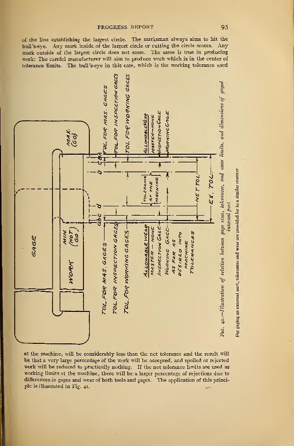
PROGRESS REPORT 95
of the line establishing the largest circle. The marksman always aims to hit the
bull's-eye. Any mark inside of the largest circle or cutting the circle scores. Anymark outside of the largest circle does not score. The same is true in producing
work: The careful manufacturer will aim to produce work which is in the center of
tolerance limits. The bull's-eye in this case, which is the working tolerance used
at the machine, will be considerably less than the net tolerance and the result will
be that a very large percentage of the work will be accepted, and spoiled or rejected
work will be reduced to practically nothing. If the net tolerance limits are used as
working limits at the machine, there will be a larger percentage of rejections due to
differences in gages and wear of both tools and gages. The application of this princi-
ple is illustrated in Fig. 41. ^
96 NATIONAL SCREW THREAD COMMISSION
(c) Disposition of Gage Tolerances.—Fig. 41 is a diagram which shows the
relative position of master-gage, inspection-gage, and working-gage tolerances with
reference to the net tolerance allowed on the work.
(1) Extreme Working Limits.—The extreme limits as shown by the lines A and a in
Fig. 41 represent the absolute limits within which all variations of the work must be
kept, including permissible variations provided for manufacturing tolerances onmaster gages. The manufacturer of the product should not be concerned with the
extreme tolerances, but should work within the net tolerance limits. The extreme
tolerance limits are included for the manufacturer or inspector of master gages, and,
in no case, should master gages be approved which are outside of the dimensions
established by these extreme limits.
(2) Net Working Tolerance Limits.—The lines at b and B represent the net working
tolerance limits within which all manufactured product must come.
(j) Master-Gage Tolerances.—The regions A B andafr represent the space required
to provide for the "Go" and "Not Go" master-gage tolerances, respectively.
(4) Master Gages Represent Net Tolerance Limits.—Master gages provide physical
standards representing the limits placed on the work. The master-gage tolerances
are placed within the extreme tolerance limits. However, the manufacturer receives
the full benefit of the specified net tolerance. So far as the manufacturer is con-
cerned, he should, in no case, permit variations in the work produced to extend
beyond the limits established by his master gages.
(5) Inspection Gage Tolerances.—The regions BC and be represent the space
required to provide for the "Go" and "Not Go" inspection-gage tolerances, respec-
tively. The inspection-gage tolerances are placed inside the net tolerance limits.
(<5) Working-Gage Tolerances.—The regions DC and dc represent the space required
to provide for the " Go " and "Not Go '
' working-gage tolerances, respectively. These
working-gage tolerances are placed within the net tolerance limits. This insures
that any work accepted by the working gage will be accepted by the inspection gage,
and that work accepted by both working gage and inspection gage will be within the
net tolerance limits.
(d) Wear on "Go" Gages.—The "Go" master gage is not to be used on the
product. It serves as a standard for comparative measurements or as a check for
verifying the inspection or working gage. It also serves as a standard representing
the wear limit for the inspection or working gage. The "Go" master gage is, there-
fore, not subject to wear.
The "Go" inspection gage may wear until it reaches the size represented by the
master gage. As shown in Fig. 41 the wear provided for the inspection gage is that
which takes place within its own tolerance region. However, a definite allowance
for wear may be provided for the "Go" inspection gage in addition to its tolerance
region if desired.
The "Go" working gage wears within its own tolerance limits and through the
inspection-gage tolerance region and continues to properly accept work until worn
to the dimension established by the "Go" master gage. It is good practice to
transfer the "Go" working gage to use as an inspection gage when it is worn so that
its dimension corresponds to that of the inspection gage.
(e) Wear on "Not Go" Gages.—The "Not Go" master gage is not to be used on
the product. It serves as a standard for comparative measurements or as a check to
verify the inspection or working gage. It is therefore not subject to wear.
The "Not Go" inspection gage wears within its own tolerance region and into the
tolerance region established for the "Not Go" working gage. It is good practice to
transfer the "Not Go" inspection gage to use as a working gage when it is worn so
that its dimension corresponds to that of the "Not Go" working gage.
The "Not Go" working gage wears within its own tolerance region into the working
tolerance. It is purely an economic question as to when the " Not Go '
' working gage
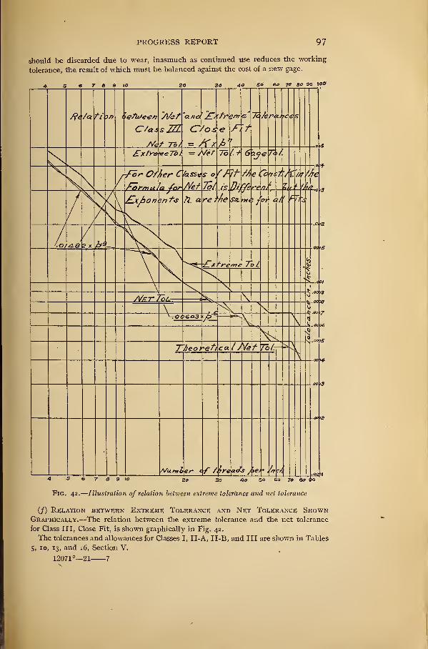
PROGRESS REPORT 97
should be discarded due to wear, inasmuch as continued use reduces the working
tolerance, the result of which must be balanced against the cost of a new gage.
40 So 60 70 SO 90 tOO
4 S 6 7 3 9 to 3 40 50 SO 70 80 SO
Fig. 42.
—
Illustration of relation between extreme tolerance and net tolerance
(/) Relation between Extreme Tolerance and Net Tolerance ShownGraphically.—The relation between the extreme tolerance and the net tolerance
for Class III, Close Fit, is shown graphically in Fig. 42.
The tolerances and allowances for Classes I, II-A, II-B, and III are shown in Tables
5, 10, 13, and 16, Section V.
12071°—21 7
98 NATIONAL SCREW THREAD COMMISSION
APPENDIX 6. GAGES AND METHODS OF TEST
The general subject of gaging screws is too extensive to be fully covered in this
report. Reference is made, however, to bulletins published by the Bureau of Stand-
ards covering various inspection methods, including the standard ring and plug
gages, and the optical projection method of gage inspection; also, to an article in the
Journal of American Society of Mechanical Engineers of February, 1919, with ref-
erence to the use of the projection lantern for gaging work.
Inasmuch as the threaded-plug and ring limit gages are the most universally used
scheme of gaging, and one that has been brought to the highest state of refinement,
there is set forth herein what is considered the best practice used in the production
and use of such gages. It is understood, however, that it is not the intention of this
commission to confine manufacturers to any particulary method of gaging, as that
would tend to hinder progress.
It has been the practice of many manufacturers including Government shops, to
work with "Go" gages only and to depend upon the judgment of good workmen to
keep within proper limits by the amount of "shake" or difference between the work
and the gage. With a highly skilled and trained force working on but one kind of
work and also referring the working gage to but one master gage, a fair degree of inter-
changeability can be maintained under these conditions.
In the recent military preparations, the Government required munitions in such
vast quantities and in such a short period of time that this method of insuring inter-
changeability failed, and a method of gaging had to be established which did not
rely entirely upon the skill and judgment of the workmen or inspectors. One reason
for the necessity of a complete gaging system was that it was not possible to obtain
a sufficient number of skilled workmen or inspectors. Furthermore, one master gage
could not be used all over the country and consequently discrepancies in measure-
ment between different shops had to be guarded against by the use of properly tested
standards and by approved methods of measuring.
It is believed that the experience gained by manufacturers producing war material
will result in a much more extensive use of gages than was ever thought practicable
during prewar times The gage specifications which are given herein cover the
manufacture, use, and application of a system of gaging which has been thoroughly
demonstrated in the execution of war contracts as being adequate for the production
in large quantities of strictly interchangeable screw-thread product. It is not the
intention of this report to limit manufacturers to any particular methods of test in
checking either the manufactured product or in measuring gages, for the reason that
any specification which would tend to limit the development of new and improved
methods of measuring would be very undesirable. However, when the ordinary
forms of thread gages are used, the specifications given herein will apply.
(a) Fundamentals.—The specifications for gages given herein are built upon the
following fundamental assumptions:
(1) Approved limit master gages do not reduce the net working tolerance.
(2) Permissible errors in angle of thread specified for "Go" gages tend to reduce the
net working tolerance, while similar permissible errors on the "Not Go" gage tend
to increase the net working tolerance . These two factors, therefore, balance each other.
(3) Permissible lead errors specified for the "Go" gage reduce the net working
tolerance, while permissable lead errors on the "Not Go" gage tend to increase the
net working tolerance.
(4) In order to realize the full net working tolerance, the permissible diametrical
variation specified for both " Go " and " Not Go '
' gages (gage increment) is placed out-
side of the net tolerance limits. The extreme tolerance equals the net tolerance plus
gage increment.
PROGRESS REPORT 99
(5) The "Go" gage should check simultaneously all elements of the thread (all
diameters, lead, angle, etc.).
(6) The "Not Go" gage should check separately the elements of the thread.
(6) General Specifications.—The following general specifications refer in par-
ticular to gaging systems which have been found satisfactory by the Army and Navyfor the production of interchangeable parts as specified under the subject of "Classi-
fication and Tolerances.'
' These specifications are included for the use of manufac-
turers where definite information is lacking. They are not to be considered mandatory
(1) Gage Classification.—Thread gages may be included in one of four classes, namely,
Standard Master Gages, Limit Master Gages, Inspection Gages, and Working Gages.
(2) Standard Master Gage.—The Standard Master Gage is a threaded plug represent-
ing as exactly as possible all physical dimensions of the nominal or basic size of the
threaded component. In order that the Standard Master Gage be authentic, the
deviations of this gage from the exact standard should be ascertained by the National
Bureau of Standards and the gage should be used with knowledge of these deviations
or corrections.
(3) Limit Master Gages.—Limit Master Gages are for reference only. They repre-
sent the extreme upper and lower tolerance limits allowed on the dimensions of the
part being produced . They are often of the same design as inspection gages. In manycases, however, the design of the master gage is that of a check which can be used to
verify the inspection or working gage.
(4) Inspection Gages.—Inspection Gages are for the use of the purchaser in accepting
the product. They are generally of the same design as the working gages and the
dimensions are such that they represent nearly the net tolerance limits on the parts
being produced. Inasmuch as a certain amount of wear must be provided on an in-
spection gage, it can not represent the net tolerance limit until it is worn to master-
gage size.
(5) Working Gages.—Working Gages are those used by the manufacturer to check
the parts produced as they are machined. It is recommended that the working gages
be made to represent limits considerably inside of the net limits in order that suffi-
cient wear will be provided for the working gages, and in order that the product
accepted by the working gages will be accepted by the inspection gages.
(6) Inspection and Working-Gage Sets for Screws.—The following list enumerates
the inspection and working gages required for producing strictly interchangeable
screws as specified for National Coarse Threads, National Fine Threads, or other
straight threads.
(i) A maximum or "Go" ring thread gage, preferably adjustable, having the re-
quired pitch diameter and minor diameter. The major diameter may be cleared to
facilitate grinding and lapping.
(ii) A minimum or "Not Go" ring thread gage, preferably adjustable, to check
only the pitch diameter of the threaded work.
(Hi) A maximum or "Go" plain ring gage to check the major diameter of the
threaded work.
(iv) A minimum or "Not Go" snap gage to check the major diameter of the
threaded work.
(7) Inspection and Working-Gage Sets for Nuts.—The following list enumerates the
inspection and working gages required for producing strictly interchangeable nuts,
as specified for National Coarse Threads, National Fine Threads, or other straight
threads.
(i) A minimum or "Go" thread plug gage of the required pitch diameter and major
diameter. The minor diameter of the thread plug gage may be cleared to facilitate
grinding and lapping.
(ii) A maximum or "Not Go" thread plug gage to check only the pitch diameter of
the threaded work.
lOO NATIONAL SCREW THREAD COMMISSION
(Hi) A "Go" plain plug gage to check the minor diameter of the threaded work.
(iv) A "Not Go '
' plain plug gage to check the minor diameter of the threaded work.
(8) Limit Master Gages Required for Checking Working or Inspection Gages Used on
Screw.—The following list enumerates the limit master gages required for the veri-
fication of the working or inspection gages as previously listed for verifying the screw.
(i) A set plug or-check for the maximum "Go" thread ring gage, having the same
dimensions as the largest permissible screw.
(it) A set plug or check for the minimum or "Not Go" thread ring gage having the
same dimensions as the smallest permissible screw.
(Hi) A maximum plain plug for checking the minor diameter of both the "Go"and "Not Go" inspection thread ring gage.
(9) Limit Master Gages Required for Checking Working or Inspection Gages Used on
Nut.—The following list enumerates the limit master gages required for the verifica-
tion of the working or inspection gages as previously listed for verifying the nut.
(1) A minimum or "Go" threaded plug to be used as a reference for comparative
measurements and corresponds to the basic dimension, or standard master gage.
(it) A maximum or'
' Not Go '
' threaded plug to be used as a reference for comparative
measurements and corresponds to the largest permissible threaded hole.
(Hi) A minimum plain ring gage to check the major diameter of the " Go " and "NotGo '
' master threaded plug unless suitable measuring facilities are available for this pur-
pose.
(10) Material.—Gages may be made of a good grade of machinery steel pack-hard-
ened, or of straight carbon steel of not less than 1 per cent carbon; or preferably of an
oil-hardening steel of approximately 1.10 per cent carbon and 1.40 per cent chromium.
(it) Handles and Marking.—Handles should be made of a good grade of machinery
steel plainly marked to identify the gage.
(c) Design and Construction.—The following specifications will be helpful in the
design and construction of gages used for producing threaded work.
(j) Plain Plug Gages.—(i) Type.—All plain plug gages should be single-ended.
Plain plug gages of 2 inches and less in diameter should be made with a plug inserted
in the handle and fastened thereto by means of a pin. Plain plug gages of more than
2 inches in diameter should have the gaging blank so made as to be reversible. This
can be accomplished by having a finished hole in the gage blank fitting a shouldered
projection on the end of the handle, the gage blank being held on with a nut.
The "Go" plain plug gage should be noticeably longer than the "Not Go" plain
plug gage, or some distinguishing feature in the design of the handle should be used to
serve as a ready means of identification, such as a chamfer on the handle of the " Go "
gage.
(2) Plain Ring Gages.—(i) Type.—Both the "Go" and "Not Go" gages should have
their outside diameters knurled if made circular.
The " Go '
' gage should have a decided chamfer in order to provide a ready means of
identification for distinguishing the "Go" from the "Not Go" gage.
(3) Snap Gages.—(i) Type.—Snap gages may be either adjustable or nonadjustable.
It is recommended that all snap gages up to and including one-eighth inch be of the
built-up type. For larger snap gages, forge blanks, flat plate stock or other suitable
construction may be used.
Sufficient clearance beyond the mouth of the gage should be provided to permit
the gaging of cylindrical work -
.
Snap gages for measuring lengths and diameters may have one gaging dimension
only, or may have a maximum and minimum gaging dimension, both on one end, or
maximum and minimum gaging dimension on opposite ends of the gage. When the
maximum and minimum gaging dimensions are placed on opposite ends of the gage,
the maximum or " Go " end of the snap gage will be distinguished from the minimum
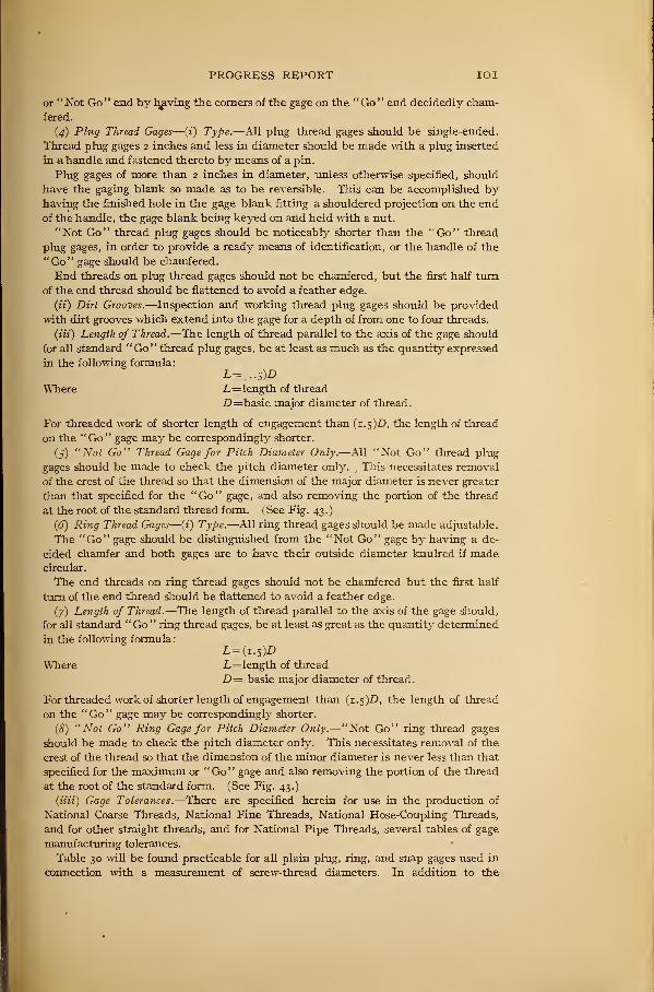
PROGRESS REPORT IOI
or " Not Go " end by heaving the comers of the gage on the " Go " end decidedly cham-
fered.
(4) Plug Thread Gages—(z) Type.—All plug thread gages should be single-ended.
Thread plug gages 2 inches and less in diameter should be made with a plug inserted
in a handle and fastened thereto by means of a pin.
Plug gages of more than 2 inches in diameter, unless otherwise specified, should
have the gaging blank so made as to be reversible. This can be accomplished byhaving the finished hole in the gage blank fitting a shouldered projection on the end
of the handle, the gage blank being keyed on and held with a nut.
"Not Go" thread plug gages should be noticeably shorter than the "Go" thread
plug gages, in order to provide a ready means of identification, or the handle of the
"Go" gage should be chamfered.
End threads on plug thread gages should not be chamfered, but the first half turn
of the end thread should be flattened to avoid a feather edge.
(it) Dirt Grooves.—Inspection and working thread plug gages should be provided
with dirt grooves which extend into the gage for a depth of from one to four threads.
(Hi) Length of Thread.—The length of thread parallel to the axis of the gage should
for all standard "Go" thread plug gages, be at least as much as the quantity expressed
in the following formula:
Where L=length of thread
D=basic major diameter of thread.
For threaded work of shorter length of engagement than (1.5)0, the length of thread
on the "Go" gage may be correspondingly shorter.
(5) "Not Go" Thread Gage for Pitch Diameter Only.—All "Not Go" thread plug
gages should be made to check the pitch diameter only. This necessitates removal
of the crest of the thread so that the dimension of the major diameter is never greater
than that specified for the "Go" gage, and also removing the portion of the thread
at the root of the standard thread form. ( See Fig. 43.)
(6) Ring Thread Gages—(t) Type.—All ring thread gages should be made adjustable.
The "Go" gage should be distinguished from the "Not Go" gage by having a de-
cided chamfer and both gages are to have their outside diameter knulred if madecircular.
The end threads on ring thread gages should not be chamfered but the first half
turn of the end thread should be flattened to avoid a feather edge.
(7) Length of Thread.—The length of thread parallel to the axis of the gage should,
for all standard "Go '
' ring thread gages, be at least as great as the quantity determined
in the following formula
:
L=(i. 5)D
Where L=length of thread
D— basic major diameter of thread.
For threaded work of shorter length of engagement than (1.5)0, the length of thread
on the "Go" gage may be correspondingly shorter.
(8) "Not Go" Ring Gage for Pitch Diameter Only.—"Not Go" ring thread gages
should be made to check the pitch diameter only. This necessitates removal of the
crest of the thread so that the dimension of the minor diameter is never less than that
specified for the maximum or "Go" gage and also removing the portion of the thread
at the root of the standard form. (See Fig. 43.)
(mi) Gage Tolerances.—There are specified herein for use in the production of
National Coarse Threads, National Fine Threads, National Hose-Coupling Threads,
and for other straight threads, and for National Pipe Threads, several tables of gage
manufacturing tolerances.
Table 30 will be found practicable for all plain plug, ring, and snap gages used in
connection with a measurement of screw-thread diameters. In addition to the
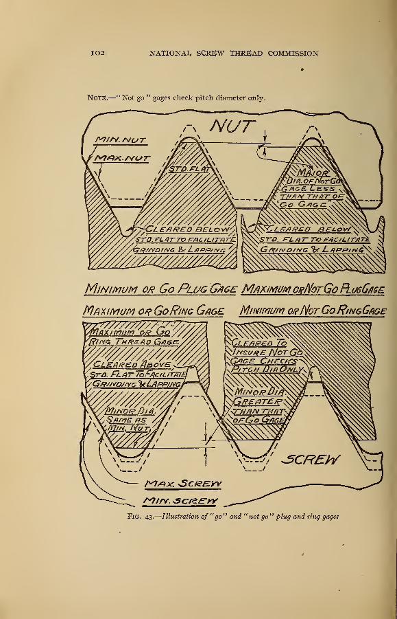
102 NATIONAL SCREW THREAD COMMISSION
NOTE.—"Not go " gages check pitch diameter only.
Minimum or Go Plug G/ige Maximum ovD/orGo FLugG/ise
Ma ximum or GoRing Gage Minimum o/f/YotGoRingGage
Fig. 43.
—
Illustration of "go" and "not go" plug and ring gages
PROGRESS REPORT 103
master-gage tolerances, suggested tolerances for inspection and working gages are
also given in Table 30.
Table 3 1 will be found practicable for both, standard and limit master thread gages
for thread work designed in accordance with, the manufacturing tolerances for Class
I, Loose Fit, and Class II, Medium Fit, made to Tables 5, 10, and 13, Section V.
Table 32 contains suggested manufacturing tolerances for inspection thread gages
with a small allowance for wear for use in quantity production of Class I , Loose Fit,
and Class II, Medium Fit thread work, made to Tables 5, 10, and 13, Section V.
Table 33 contains suggested manufacturing tolerances for working thread gages
with a small allowance for wear for use in quantity production of Class I, Loose Fit,
and Class II, Medium Fit thread work, made to Tables 5, 10, and 13, Section V.
Table 34 contains the tolerances suggested for both standard and limit master thread
gages for work designed in accordance with manufacturing tolerances for Class III,
Close Fit thread work, made to Table 16, Section V. As the component tolerances for
this class are relatively small, it is believed that the working gages will be required to
be held within the gage tolerances shown in Table 34.
(e) Application of Gage; Tolerances.—(j) Tolerancesfor Plain Gages.—For plain
plug gages, plain ring gages, and plain snap gages required for measuring diameters of
screw-thread work, the gage tolerances specified in Tables 31, 32, 33, and 34 should be
used. Attention is called to the fact that the tolerances on thread diameters vary in
accordance with the number of threads per inch on the screw or nut being manufac-
tured. In manufacturing a plain plug, ring or snap gage, in the absence of information
as to the number of threads per inch of the screw to be made, or for gage dimensions
other than thread diameters, the tolerances for plain gages given in Table 30 may be
used.
(2) Tolerances on Lead.—The tolerances on lead are specified as an allowable varia-
tion between any two threads not farther apart than the length of thread engagement
as determined by the following formula:
(3) Tolerances on Angle of Thread.—The tolerances on angle of thread as specified
herein for the various pitches are tolerances on one-half of the included angle. This
insures that the bisector of the included angle will be perpendicular to the axis of the
thread within proper limits. The equivalent deviation from the true thread form
caused by such irregularities as convex or concave sides of thread, rounded crests, or
slight projections on the thread form, should not exceed the tolerances allowable on
angle of thread.
(4) Tolerances on Diameters.—The tolerances given for thread diameters in Tables
31, 32, 33, and 34 are applied in such a manner that the tolerances permitted on the
inspection and working gages occupy part of the extreme tolerance. This insures that
all work passed by the gages will be within the tolerance limits specified on the part
drawing as represented by the limit master gages. The tolerances given also permit
the classification and selection of gages, so that if a gage is not suitable for a master gage
it may be classified and used as an inspection or working gage, provided that the errors
do not pass outside of the net tolerance limits.
The application of the tolerances on diameters of thread gages is exactly the same
as explained herein for plain gages. Example: Dimensions on component drawings.
Work to be gaged:
Hole 1. 250+0. 004=1. 254 max.
L=(i. S)Dwhere
L=length of thread engagement
D=basic major diameter of thread.
Shaft, I. 248+ . OOO'
—. C04
—. ooo- 1. 250 min.
1. 248 max.
1. 244 min.
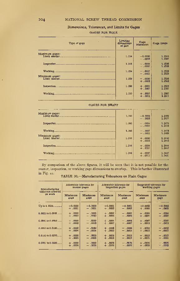
104 NATIONAL SCREW THREAD COMMISSION
Dimensions, Tolerances, and Limits for Gages
GAGES FOR HOLE
_Type of gage
Limitingdimensions
of part
Gagetolerances
Gage limits
vi mil 171 trjiffPS *
Limit master 1. 254 —
<
). 0000 1. 2540.0003 1. 2537
Inspection 1. 254 .0004 1. 2536.0007 1. 2533
Working 1. 254 . 0007 1. 2533. 0011 1. 2529
Minimum gages:Limit master 1. 250 + .0000 1. 2500
+ . 0003 1. 2503
1. 250 + . 0004 1. 2504
+ .0007 1. 2507
Working 1. 250 + .0007 1. 2507
+ .0011 1. 2511
GAGES FOR SHAFT
Maximum gages:Limit master 1. 248 —
). 0000 1. 2480. 0003 1. 2477
Inspection 1. 248 . 0004 1. 2476. 0007 1. 2473
1. 248 .0007 1. 2473.0011 1. 2469
Minimum gages:1. 244 + .0000 1. 2440
+ .0003 1. 2443
1. 244 + .0004 1. 2444
+ .0007 1. 2447
Working 1. 244 + .0007 1. 2447
+ .0011 1. 2451
By comparison of the above figures, it will be seen that it is not possible for the
master, inspection, or working gage dimensions to overlap. This is further illustrated
in Fig. 44.TABLE 30.—Manufacturing Tolerances on Plain Gages
Manufacturingtolerance allowed
on work
Allowable tolerance for
master gages
Minimumgage
Maximumgage
Allowable tolerance for
inspection gages
Minimumgage
Maximumgage
Suggested tolerance for
working gages
Minimumgage
Maximum
Up to 0. 0020
0.0021 to 0.0040....
0.0041 to 0.0060....
0.0061 to 0.0100....
0.0101 to 0.0200
0. 0201 to 0. 0500
+0.0000+ .0001
+ .0000
+ .0002
+ .0000
+ .0003
+ .0000
+ .0004
+ .0000
+ .0005
-0.0000- .0001
.0000
.0002
.0000
.0006
.0000
.0003
.0000
.0004
.0000
.0005
.0000
.0006
+ 0.0001
+ .0003
+ .0002
+ .0004
+ .0004
+ .0007
+ .0006
+ .0010
.0010
.0015
+ .0020
+ .0026
-0.0001- .0003
.0002
.0004
.0004
.0007
.0006
.0010
.0010
.0015
.0020
.0026
+0. 0003
+ .0005
+ .0004
+ .0007
+ .0007
+ .0011
+ .0010+ .0015
+ .0015
+ .0021
+ .0026
+ .0033
-0.0003- .0005
.0004
.0007
.0007
.0011
.0010
.0015
.0015
.0021
.0026
.0033
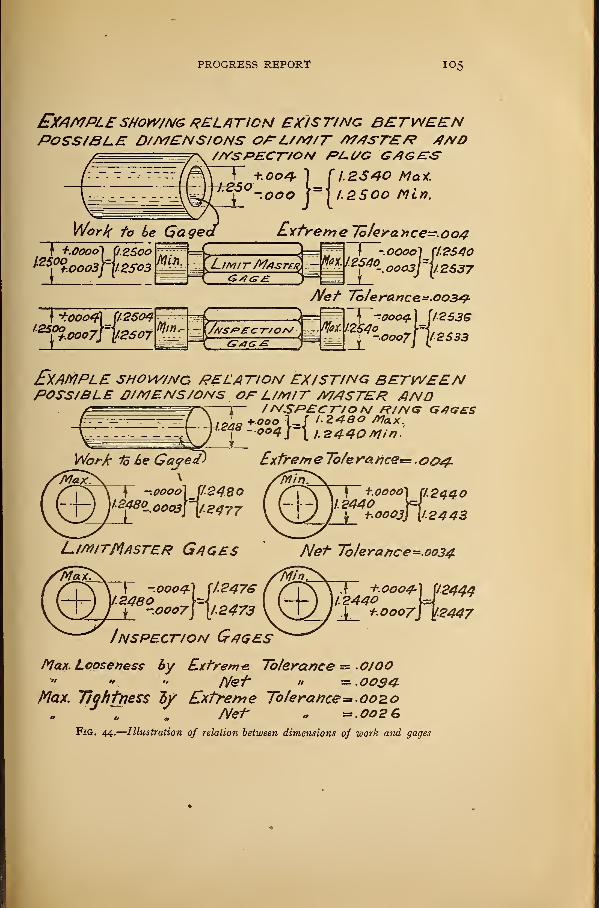
PROGRESS REPORT I05
EXAMPLESHOWING RELATION existing betweenPOSSIBLE DIMENSIONS OA~L/M/T WASTES? ANO
//VSPECT/ON Pl~(SG G/?G£T<S
2S40 Mat.
2S0O Min.
\ +ooo4\ [12504
'^ft.ooo7T)l.2S07
Net To/eranee- 003^9-
^-0004} 536
2533-00071 //J
Example show/nc relation ex/st/ng betweenPOSSIBLE ll/MENS/ONS OF L/M/T MASTER AND
/MSPEC 7-/0 A/ /?//V<y GtiGESIf I.Z4BO Max.J 1 I.Z440 Min'.
Work io he Gajed
y -.0000] ri.
IZ48°-.ooo3y\l.
7-2480
2477
£xtre/rje To/e ra.nce= .004.
Kn V
LimiTMfiSTER Gages
} +.0O0O]1.2440
i-.OOOjJ
2440
2443
Net Tolerance -.0034
~Y -.00042480^ ".0007
J I'-
Inspection Gages
+.0004A [124441.2440 U ^
+.0007] y.2447
Max. Looseness by Extreme. Tolerance — 0J00" " " Net" » —.0034
Max. Tightness iy Extreme To/erance= 002,0Net =.oo2G
Fig. 44.
—
Illustration of relation between dimensions of work and gages
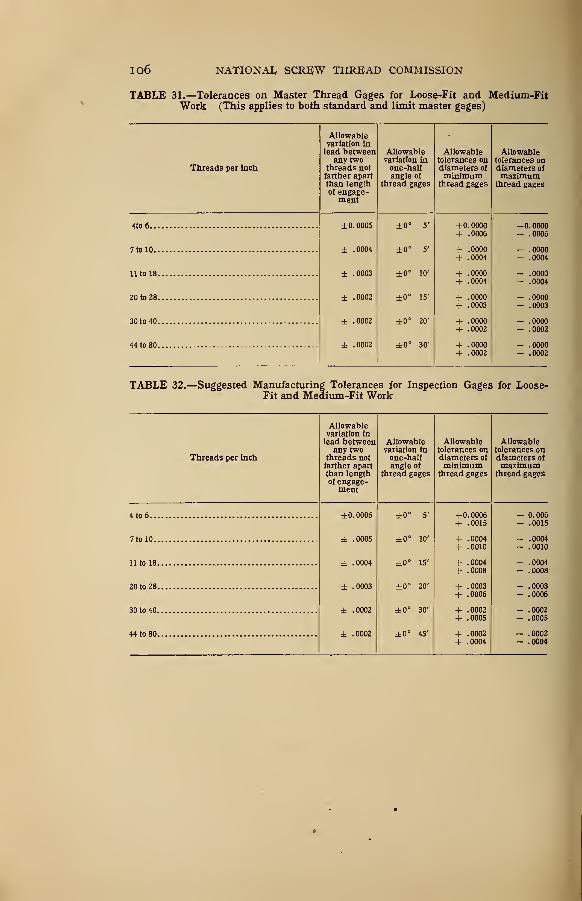
io6 NATIONAL SCREW THREAD COMMISSION
TABLE 31.—Tolerances on Master Thread Gages for Loose-Fit and Medium-FitWork (This applies to both standard and limit master gages)
Threads per inch
Allowablevariation inlead between
any twothreads notfarther apartthan lengthof engage-ment
Allowablevariation inone-halfangle of
thread gages
Allowabletolerances ondiameters of
minimumthread gages
Allowabletolerances ondiameters ofmaximum
thread gages
<to 6 ±0. 0005 ±0° 5' + 0.0000 — u. uuuu+ .0006 - .0006
7 to 10 . ± .0004 ±0° 5' + .0000 - .0000
+ .0004 - .0004
11 to 18 ± .0003 ±0° 10' + .0000 - .0000
+ .0004 - .0004
20 to 28 ± .0002 ±0° 15' + .0000 - .0000
+ .0003 - .0003
30 to 40 ± .0002 ±0° 20' + .0000 - .0000
+ .0002 - .0002
44 to 80 ± .0002 ±0° 30' + .0000 - .0000
+ .0002 - .0002
TABLE 32.—Suggested Manufacturing Tolerances for Inspection Gages for Loose-Fit and Medium-Fit Work
Threads per inch
Allowablevariation inlead between
any twothreads notfarther apartthan lengthof engage-
ment
Allowablevariation inone -half
angle of
thread gages
Allowabletolerances ondiameters of
minimumthread gages
Allowabletolerances ondiameters of
maximumthread gages
4 to 6.
.
7 to 10.
11 to 18
20 to 28
30 to 40
44 to 80
±0.0006
± .0005
± .0004
± .0003
± .0002
± .0002
±0° 5'
±0° 10'
±0° 15'
±0° 20'
±0° 30'
±0° 45'
+ 0.0006 0.006+ .0015 .0015
+ .0004 .0004+ .0010 .0010
+ .0004 .0004+ .0008 .0008
+ .0003 .0003+ .0006 .0006
+ .0002 .0002
+ .0005 .0005
+ .0002 .0002+ .0004 .0004
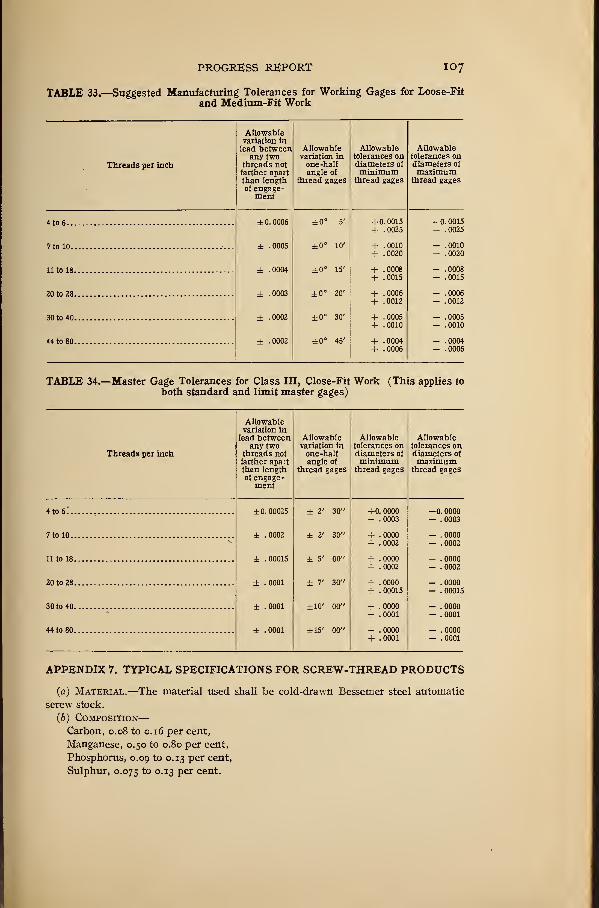
PROGRESS REPORT 107
TABLE 33.—Suggested Manufacturing Tolerances for Working Gages for Loose-Fit
and Medium-Fit Work
Threads per inch
Allowablevariation in
lead betweenany two
threads notfarther apartthan lengthof engage-
ment
Allowablevariation inone -halfangle of
thread gages
Allowabletolerances ondiameters of
minimumthread gages
Allowabletolerances ondiameters of
maximumthread gages
4to6 ^ ±0.0006 ±0° 5' +0.0015 —0.0015+ .0025 - .0025
7 to 10 ± .0005 ±0° 10' + .0010 - .0010
+ .0020 - .0020
11 to 18 ± .0004 ±0° 15' + .0008 — .0008.0015 - .0015
20 to 28 ± .0003 ±0° 20' + .0006 - .0006
+ .0012 - .0012
30 to 40 ± .0002 ±0° 30' + .0005 - .0005
+ .0010 - .0010
44 to 80 ± .0002 ±0° 45' + .0004 - .0004
+ .0006 - .0006
TABLE 34.—Master Gage Tolerances for Class III, Close-Fit Work (This applies to
both standard and limit master gages)
Threads per inch
Allowablevariation in
lead betweenany two
threads notfarther apa:tthan lengthof engage-ment
Allowablevariation inone-halfangle of
thread gages
Allowabletolerances ondiameters of
minimumthread gages
Allowabletolerances ondiameters of
maximumthread gages
4 to 6..
7 to 10.
11 to 18
20 to 28
30 to 40
44 to 80
±0. 00025
± .0002
± .00015
± .0001
± .0001
± .0001
± 2' 30"
± 2' 30"
± 5' 00"
± 7' 30"
±10' 00"
±15' 00"
+0. 0000+ .0003
-0. 0000- .0003
+ . 0000+ .0002
- .0000- . 0002
+ . 0000+ . 0002
- . 0000- . 0002
+ . 0000+ .00015
- . 0000— . 00015
+ .0000+ .0001
- . 0000- . 0001
+ . 0000+ .0001
- . 0000- . 0001
APPENDIX 7. TYPICAL SPECIFICATIONS FOR SCREW-THREAD PRODUCTS
(a) Material.—The material used shall be cold-drawn Bessemer steel automatic
screw stock.
(6) Composition—Carbon, 0.08 to 0.16 per cent,
Manganese, 0.50 to 0.80 per cent,
Phosphorus, 0.09 to 0.13 per cent,
Sulphur, 0.075 to 0.13 per cent.
I08 NATIONAL SCREW THREAD COMMISSION
(c) Method op Manufacture.—Bolts and nuts may be either rolled, milled, or
machine cut, so long as they meet the specifications herein provided.
(d) Workmanship.—All bolts and nuts must be of good workmanship and free
from all defects which may affect their serviceability.
(e) Finish.—All bolts and nuts to be semifinished; that is, the bodies to be ma-
chined, underside of head and nut faced, upper face of head and nut to be chamfered
at an angle of 30°, leaving a circle equal in diameter to the width of the nut.
(J) Form of Thread.—The form of thread shall be the National Form, as speci-
fied in Section III herein, and formerly known as the United States Standard or
Sellers Thread.
(#) Thread SERIES.—The pitches and diameters shall be as specified in Table 1,
Section IV, herein, and known as the National Coarse-Thread Series.
(h) Class of Fit.—Class II-A, Medium Fit (Regular).
(») Dimensions—
•
(1) Nominal size: X inch.
(2) Number of threads per inch: 13.
(3) Length under head : 3 inches ±0.05".
- (4) Minimum length of usable thread: 1 inch.
(5) Diameters: See Table 11, Section V.
(j) Tolerances and Allowances.—See Table 10, Section V.
(k) Nuts—(1) Form: Hexagonal.
(2) Thickness: % inch io.oi".
(3) Short diameter (across flats) : ]/i inch/"'"'000
'
l— .005 .
(I) Heads—(1) Form: Hexagonal.
(2) Thickness: inch io.oi".
(3) Short diameter (across flats) :
7/$ inch{^~°'°
00'
I— .005".
(m) Gages.—The gages used shall be such as to insure that the product falls
within the tolerances as specified herein for Class II, Medium Fit (Regular).
The following gages are suggested and will be used by the purchaser
:
For the screw—(1) A maximum or "Go" ring thread gage.
(2) A minimum or "Not Go" ring thread gage to check only the pitch diameter
of the thread.
(3) A maximum or "Go" plain ring to check the major diameter of the thread.
(4) A minimum or " Not Go" snap gage to check the major diameter of the thread.
For the nut—(1) A minimum "Go" thread plug gage.
(2) A maximum or "Not Go '
' thread plug gage to check only the pitch diameter.
(3) A "Go" plain plug gage to check the minor diameter.
(4) A "Not Go" plain plug gage to check the minor diameter of the thread.
(w) Inspection and Test.—Screws and nuts shall be inspected and tested as
follows:
At least three bolts and nuts shall be taken at random from each lot of ioo, or
fraction thereof, and carefully tested. If the errors in dimensions of the screws or
nuts tested exceed the tolerance specified for this class, the lot represented by these
samples shall be rejected.
(0) Delivery.—Unless otherwise specified the assembled bolts and nuts are to be
delivered in substantial wooden containers, properly marked, and each containing
100 pounds.
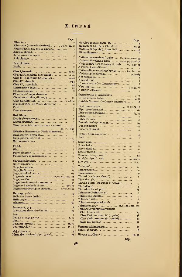
X. INDEX
PageAllowance 7
Allo.wance (numerical values) 29, 38, 44, 52
Angle of helix {see Helix angle) 7
Angle of thread 7
Arrangement of report 5
Axis of screw 7
Base of thread 7
Basic 8
Class I, loose fit 23-32
Class II-A, medium fit (regular) 33-40
Class II-B, medium fit (special) 41-46
Class in, close fit 47-54
Class IV, wrench fit 55
Classification of fits 22
Clearance, crest 8
Clearance at major diameter '. 11
Clearance at minor diameter 11
Close fit, Class III " 47-54
Core diameter {see Minor diameter) 6
Crest 7
Crest clearance 8
Definitions 6
Depth of engagement 7
Depth of thread 7
Direction of tolerance on screw and nut 24,
33.41,47; 55
Effective diameter {see Pitch diameter) 6
Engagement, depth of 7
Engagement, length of 7, 23
Extreme tolerance 7
Finish 8
Sit 8
Form of thread 9
Future work of commission 84
Gage classification 60
Gage increment 8
Gage, inspection 60
Gage, limit master 60
Gage, standard master 60
Gage tolerances 81,82, 104, ro6, 107
Gage, working 60
Gages (fundamental statements) 58
Gages and methods of test 98-107
Gages for national pipe threads 63-66, 69-71
Hearings, public 89
Helix {see Screw helix) 6
Helix angle 7
Historical 93
Increment, gage 8
International standardization 84
Lead 7
Length of engagement 7, 23
Limits 8Locknut threads 67,76
Loose fit, Class 1 23-32
Major diameter 6
Manual on national pipe threads 60
PageMarking of tools, gages, etc
gMedium fit (regular), Class II-A 33-40Medium fit (special),' Class II-B 4i-46Minor diameter g
National coarse thread series. . . . 17,19,30,39,45,53National fine thread series 1 7, 20, 31, 40, 46, 54Nationalfirehose coupling threads . . . 16,18,20,32Nationalform ofthread
9Nationalhosecouplingthreads 13, 18, 2r, 32National pipe threads 19,60-83Net tolerance gNeutral zone . gNomenclature {see Terminology) 6Notation 10,73,75,76Number of threads
7
Organization of commissionSt gy
Origin of commission4j gg
Outside diameter {see Major diameter) 6
Pipe thread gages 63-66,69-71Pipe thread manual g
Pipe threads, straight 67,75Pitch ' -
Pitch diameter gProcedure of commission g9Public hearings g9Purpose of report .
Report, arrangement of
Root5
7
7
6
6
7
60
Screw axis
Screw helix
Screw thread
Side of thread
Standard temperature
Straight pipe threads 67, 75Symbols 8, 67
Technical
Temperature
Terminology
Thread (see Screw thread)
Thread angle
Thread depth {see Depth of thread)
Thread form
Thread series adopted
Tolerance (definition of)
Tolerance, extreme
Tolerance, net 8
Tolerance (explanation of) 56
Tolerances, gage 81, 82, 104, 106, 107
Tolerances (numerical values)
;
Class I, loose fit 29
Class II-A, medium fit (regular) 38
Class II-B, medium fit (special) 44
Class III, close fit 52
Uniform minimum nutUtility of report
23
5
Wrench fit , Class IV 23,55
109


![DEPARTMENT OF COMMERCE - nvlpubs.nist.gov · departmentofcommerce bureauofstandards georgek.burgess,director technologicpapersofthebureauofstandards,no.330 [partofvol.21] resistanceofconductorsofvarious](https://img.pdfslide.net/doc/110x75/5b16d4727f8b9a596d8e0677/department-of-commerce-departmentofcommerce-bureauofstandards-georgekburgessdirector.jpg)


![ELECTRODEPOSITION OF CHROMIUM - NIST€¦ · DEPARTMENTOFCOMMERCE BUREAUOFSTANDARDS GeorgeX.Burgess,Director TECHNOLOGICPAPERSOFTHEBUREAUOFSTANDARDS,No.346 [PartofVol.21] ELECTRODEPOSITIONOFCHROMIUM](https://img.pdfslide.net/doc/110x75/5f0770127e708231d41cfb38/electrodeposition-of-chromium-nist-departmentofcommerce-bureauofstandards-georgexburgessdirector.jpg)

![UNITED STATES STANDARD TABLES FOR PETROLEUM OILS · DEPARTMENTOFCOMMERCE Circular OFTHE BureauofStandards S.W.STRATTON,Director No.57 UNITEDSTATESSTANDARDTABLES FORPETROLEUMOILS [1stEdition]](https://img.pdfslide.net/doc/110x75/5f199b8afdb6f054802f5d3e/united-states-standard-tables-for-petroleum-oils-departmentofcommerce-circular-ofthe.jpg)

![DEPARTMENT of commerce - NIST · DEPARTMENTOFCOMMERCE Circular ofTHE BureauofStandards No.62 SOAP [ThirdEdition] JANUARY24,1923 PRICE,5CENTS SoldonlybytheSuperintendentofDocuments](https://img.pdfslide.net/doc/110x75/60d4a058b5815513a2289494/department-of-commerce-nist-departmentofcommerce-circular-ofthe-bureauofstandards.jpg)