Embed Size (px)
Citation preview
Technical Description
Document Title XCell RTU Architectural Description Revision 103 Revision Date April 30, 2003 By Detlef Raddatz File Name RTU Architecture Description.doc
Copyright: This document contains proprietary information of Microsol Limited. None of the information contained in this document may be reproduced or disclosed to others without written authorisation by Microsol Limited. The information in this document is subject to change without prior notice and should not be construed as a commitment by Microsol. Microsol do not assume responsibility for any errors which may be in this document.
RTU Architecture Description
Page 1 of 56
Revision History
Date Rev Author Comments
14/02/2003 101 Detlef Raddatz More details added
30/03/2003 102 Andrew Umney Changed to CPR-041 diagrams
20/07/2003 103 Mick Davis Descriptions for fieldNet, multiple master stations and healthpoints
RTU Architecture Description
Page 2 of 56
1 Definitions..................................................................................................... 3
2 XCell RTU Architecture................................................................................ 4
2.1 Overview ..........................................................................................................4
2.2 Basic Cell Unit .................................................................................................4
2.3 Multi-cell RTU ..................................................................................................5
2.4 Functionality ....................................................................................................6
2.5 System Integrity...............................................................................................7
2.6 Processing Power ...........................................................................................7
2.7 Expansion ........................................................................................................8
2.8 Spares and Maintenance.................................................................................8
3 RTU Communication Configurations ......................................................... 9
3.1 Introduction .....................................................................................................9
4 Tools............................................................................................................ 11
5 RTU DC Power............................................................................................ 12
6 Plant Interfaces .......................................................................................... 13
6.1 Plant Interface Modules ................................................................................13
7 Input / Output Processing ......................................................................... 27
7.1 Digital Inputs..................................................................................................27
7.2 Controls .........................................................................................................33
7.3 Analogue Measurements ..............................................................................38
7.4 Analogue Outputs .........................................................................................40
7.5 Accumulators.................................................................................................41
8 RTU Diagnostic Indications....................................................................... 43
9 Time Synchronisation................................................................................ 44
10 FieldNet ....................................................................................................... 45
11 XCell Software Structure ........................................................................... 46
11.1 Introduction................................................................................................46
11.2 Cell Based Software Modules ...................................................................47
11.3 Data Transfer Initiation..............................................................................48
11.4 Peer to Peer Communications ..................................................................49
11.5 The XCell Software Base System .............................................................50
RTU Architecture Description
Page 3 of 56
1 Definitions AIN Analogue Input AOT Analogue Output BCD Binary Coded Decimal DDI Double Digital Input DOT Digital Output IOCB Input/Output Carrier Board LAN Local Area Network LED Light Emitting Diode RTU Remote Terminal Unit SDI Single Digital Input SOE Sequence of Events TAP Transformer Position
RTU Architecture Description
2 XCell RTU Architecture
2.1 Overview The XCell RTU is based on the advanced and powerful XCell architecture. This is a modular and flexible architecture designed to meet both present and future requirements. Using its multi-processor approach it provides high performance with high availability and has the power to meet the most demanding site requirements. It is based on double eurocard, 19” rack mounted modules. These are designed using standard electronic components and manufactured to ISO 9001 standards.
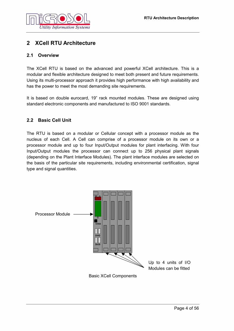
2.2 Basic Cell Unit The RTU is based on a modular or Cellular concept with a processor module as the nucleus of each Cell. A Cell can comprise of a processor module on its own or a processor module and up to four Input/Output modules for plant interfacing. With four Input/Output modules the processor can connect up to 256 physical plant signals (depending on the Plant Interface Modules). The plant interface modules are selected on the basis of the particular site requirements, including environmental certification, signal type and signal quantities.
Basic XCell Components
Processor Module
Up to 4 units of I/OModules can be fitted
Page 4 of 56

RTU Architecture Description
2.3 Multi-cell RTU RTUs with more plant interface signals simply require multiple cells. These combine to form larger and more powerful RTUs.
The cells communicate wsystem. This integrates t Data sourced in any celFieldNet communicationsindividual cells and availa
2 3
Cell 1Larger RTU comp
ith each other on he individual cells
l is available to a provide a globallble to all cells.
1
Cell
rised of Multiple C
XCell’s sophisticainto one unified R
ll cells. The indivy available databa
Cell
3
Cell Cell 2 CellRack 2
Rack 1
Page 5 of 56
ells
ted FieldNet communications TU.
idual cells combined with the se which is populated by the
RTU Architecture Description
Page 6 of 56
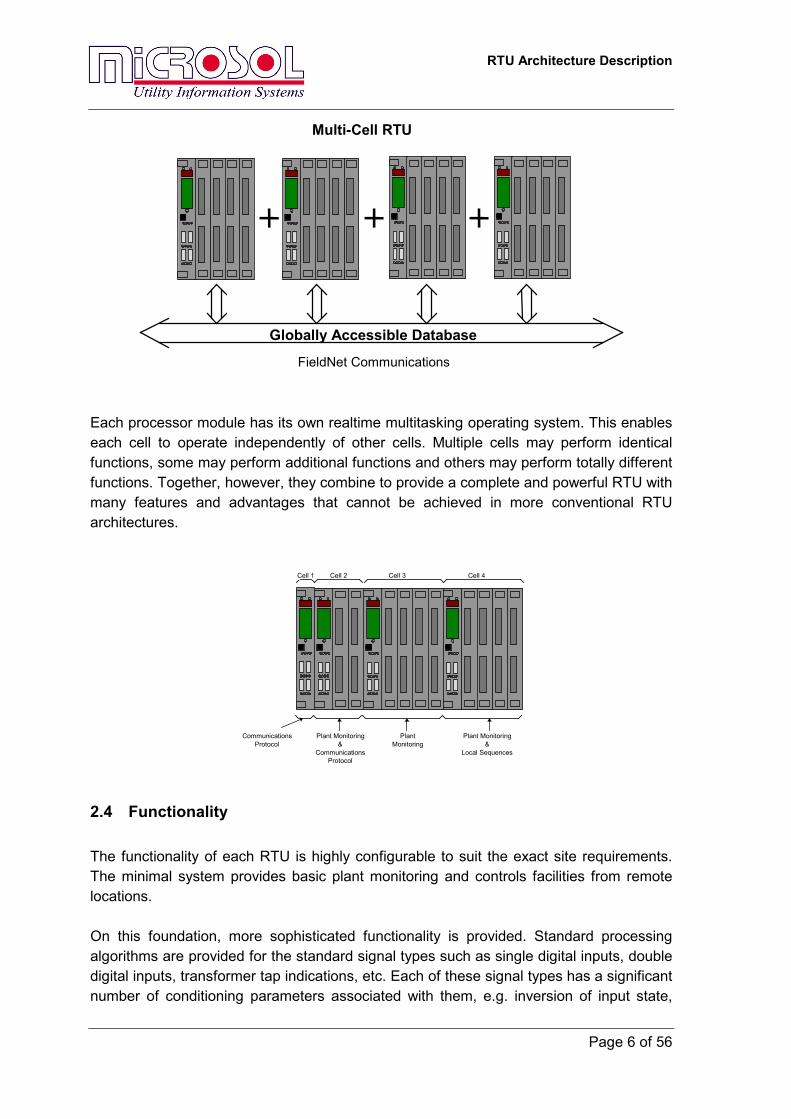
Globally Accessible Database
FieldNet Communications
Multi-Cell RTU
Each processor module has its own realtime multitasking operating system. This enables each cell to operate independently of other cells. Multiple cells may perform identical functions, some may perform additional functions and others may perform totally different functions. Together, however, they combine to provide a complete and powerful RTU with many features and advantages that cannot be achieved in more conventional RTU architectures.
Cell 3 Cell 4Cell 2Cell 1
Plant Monitoring&
Local Sequences
PlantMonitoring
Plant Monitoring&
CommunicationsProtocol
CommunicationsProtocol
2.4 Functionality The functionality of each RTU is highly configurable to suit the exact site requirements. The minimal system provides basic plant monitoring and controls facilities from remote locations. On this foundation, more sophisticated functionality is provided. Standard processing algorithms are provided for the standard signal types such as single digital inputs, double digital inputs, transformer tap indications, etc. Each of these signal types has a significant number of conditioning parameters associated with them, e.g. inversion of input state,
RTU Architecture Description
Page 7 of 56
filter times, scaling parameters etc. These can all be configured on a point by point basis. For more advanced systems, the RTU supports user application programming. With this, the customer can develop general or site specific application programs in a graphical environment. This allows user applications to be developed in any of five programming environments; Ladder Diagrams, Sequential Function Charts, Function Block Diagrams, Structured Text and Instruction List. This is in accordance with the IEC 1131 application development standards. This allows the customer to tailor the RTU to the exact site requirements. Other functionality, such as protocol implementation and more general application software are configurable to provide a flexible solution to the customer. Configuration of operating parameters is provided by Workbench, a Windows XP based configuration tool. User application development is provided by eXpress, a Windows based IEC 1131 development environment.
2.5 System Integrity An RTU is a fundamental part of system operations, RTU availability is of paramount importance. The XCell RTU was designed with this in mind. It is for this reason that the XCell RTU is redundant in critical elements to provide the highest possible availability. These critical elements include: • Dual DC power feed to each cell • Each XCell processor module is fitted with its own DC-DC converter to generate the
required voltage levels for use within that cell. This ensures independence and isolation between units.
• Multiple processors can be used for communications to the Control Centre • Failure of a cell is localised to the cell and the loss of functionality provided by that cell
only • Application programs can be duplicated in multiple cells to ensure higher application
integrity and/or availability • Integrity bits associated with all RTU data to signify whether the data is valid (e.g. the
hardware is good) • There is an option for redundant optical FieldNet communications between cells
2.6 Processing Power Each processor module within the RTU monitors a finite number of physical plant signals (up to 256). This reflects a significant under-utilisation of the processor for standard RTU applications. As the size of the RTU increases, so does the number of cells. Each cell still handles a maximum of 256 physical plant signals. This ensures that performance does not decrease with increasing signal count, and 1ms time stamping can always be
RTU Architecture Description
Page 8 of 56
achieved on all inputs regardless of the signal count.
2.7 Expansion The XCell RTU is easily expandable by simply adding more cells. If there is insufficient expansion room in an existing enclosure, the RTU can be extended into another enclosure by extending the FieldNet communications into that enclosure.
2.8 Spares and Maintenance As the XCell RTU is designed using a small number of standard modules, the number of spare parts required can be minimised. Each cell has comprehensive diagnostic facilities to aid in fault finding and reduce system downtime. PC based diagnostic tools for the XCell RTU also help in this regard.
RTU Architecture Description
Page 9 of 56
3 RTU Communication Configurations
3.1 Introduction Depending on the application, Xcell RTUs can provide various levels of communication redundancy, as well as multiple protocol options.
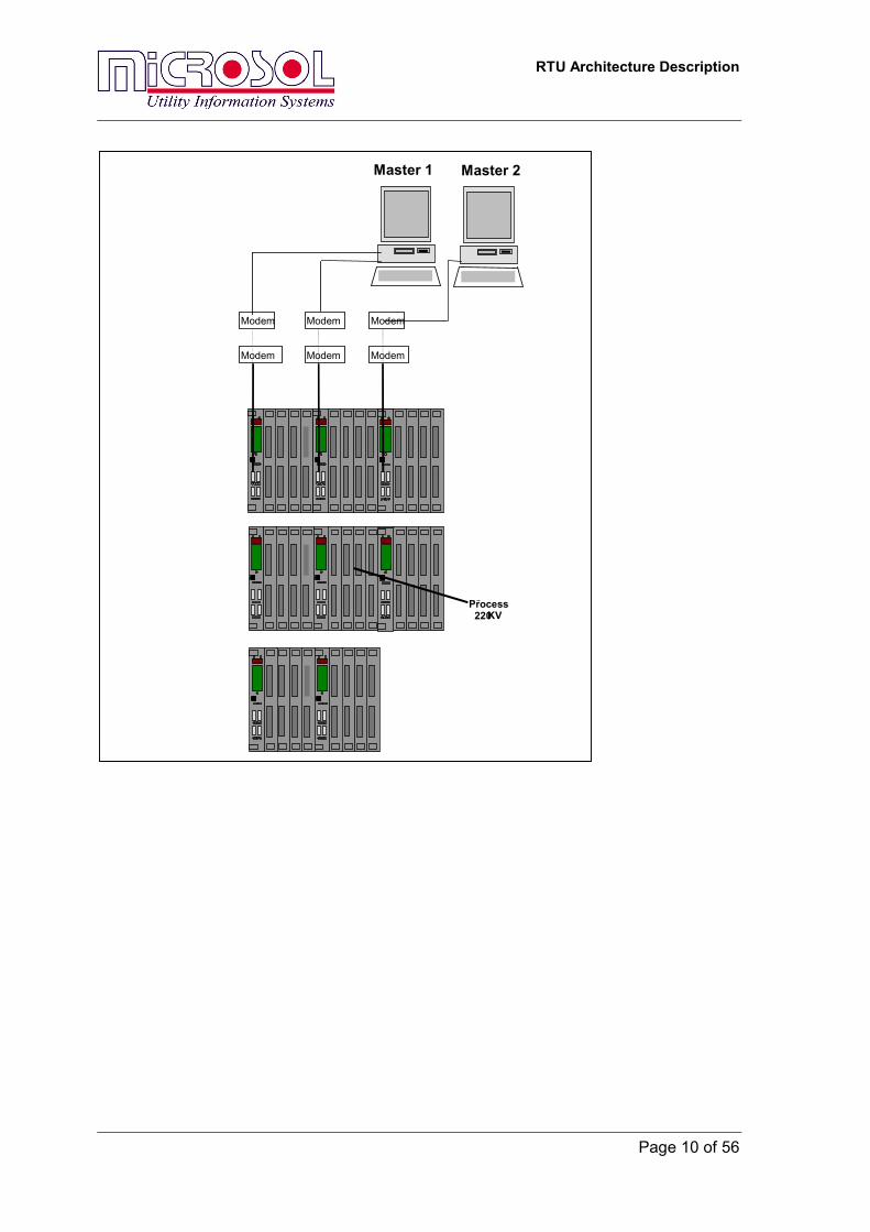
3.1.1 Dual Communications RTUs RTUs may have two communication processors for dual communication to two Master Stations. Additional processors support I/O modules for general station alarms and indications. All processor modules are fitted with sufficient memory for the data storage associated with the communication protocol(s).
3.1.2 Redundant Communications RTUs Each RTU has two interface processors for redundant communications to a Master Station. These processor modules are fitted with sufficient memory for the data storage associated with the communication protocol, and can also support I/O modules.
3.1.3 Standard Communications RTUs Each RTU has just one processor for communications with a Master Station. This processor module is fitted with sufficient memory for additional data storage associated with the communication protocol and can also support I/O modules.
RTU Architecture Description
Page 10 of 56
Modem
Modem
Modem
Modem
Master 1
I/OProcess 220KV
L l
Modem
Modem
Master 2
RTU Architecture Description
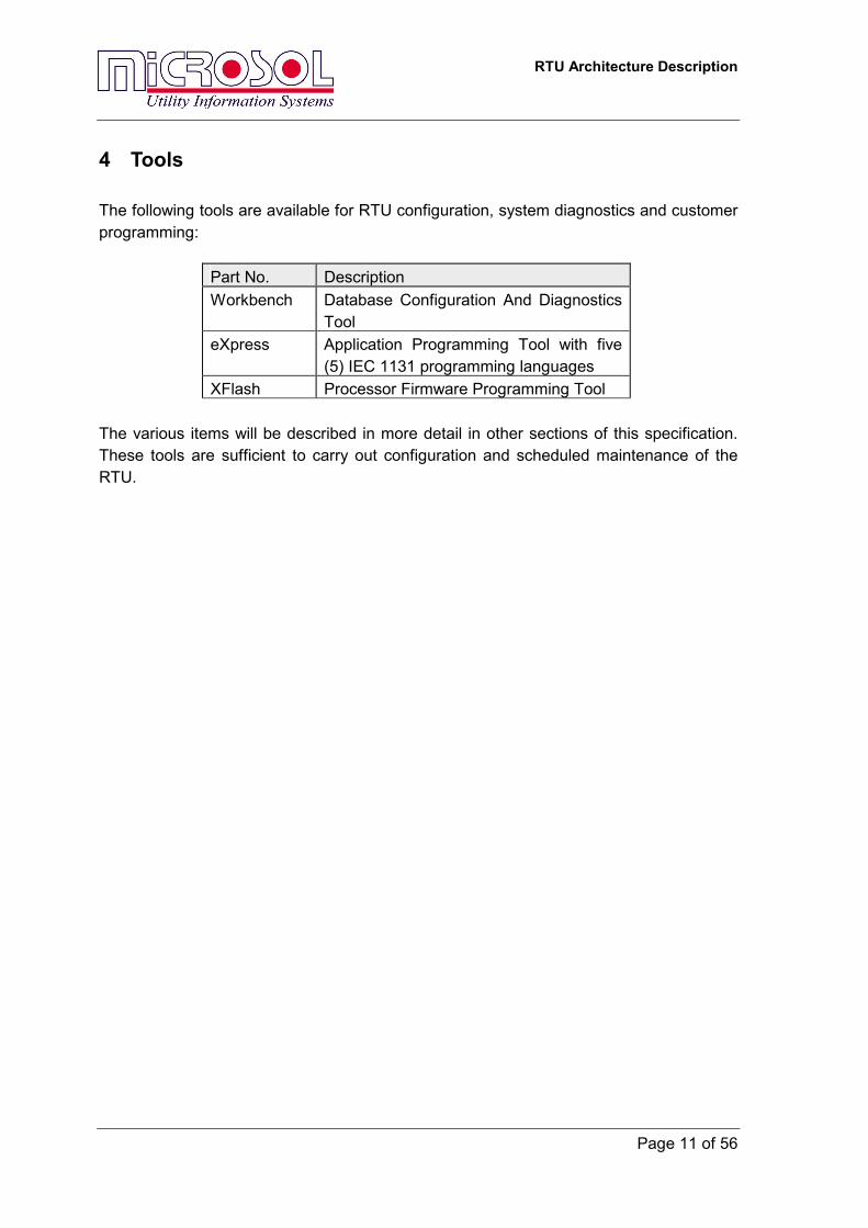
4 Tools The following tools are available for RTU configuration, system diagnostics and customer programming:
Part No. Description Workbench Database Configuration And Diagnostics
Tool eXpress Application Programming Tool with five
(5) IEC 1131 programming languages XFlash Processor Firmware Programming Tool
The various items will be described in more detail in other sections of this specification. These tools are sufficient to carry out configuration and scheduled maintenance of the RTU.
Page 11 of 56
RTU Architecture Description
Page 12 of 56
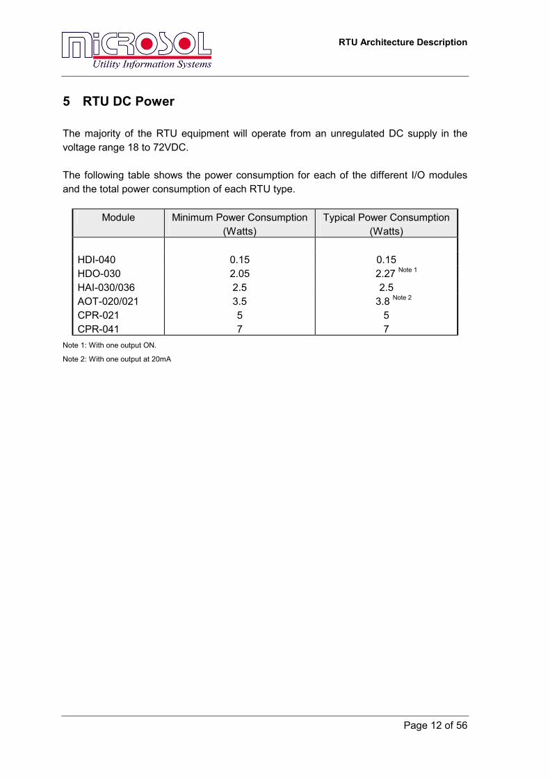
5 RTU DC Power The majority of the RTU equipment will operate from an unregulated DC supply in the voltage range 18 to 72VDC. The following table shows the power consumption for each of the different I/O modules and the total power consumption of each RTU type.
Module Minimum Power Consumption (Watts)
Typical Power Consumption (Watts)
HDI-040 0.15 0.15 HDO-030 2.05 2.27 Note 1 HAI-030/036 2.5 2.5 AOT-020/021 3.5 3.8 Note 2 CPR-021 5 5 CPR-041 7 7
Note 1: With one output ON.
Note 2: With one output at 20mA
RTU Architecture Description
Page 13 of 56
6 Plant Interfaces
6.1 Plant Interface Modules Each RTU contains a range of XCell Input / Output modules for monitoring and control of plant items. All modules are certified for use in electrically noisy environments, The following XCell modules are used in the RTUs: 1. CPR-041 Processor Module 2. HDI-040 Digital Input Module 3. HDO-030 Digital Output 4. HAI-030/036 Analogue Input 5. AOT-021 Analogue Output Module 6. IOCB-020 Input Output Carrier Board Plant interface connections to the modules are via D-Type connectors on the front of each module. All modules are labelled such that their position in the rack is clearly identifiable.
6.1.1 Processor Module • The Processor Modules are CPR-041s. • Each incorporates a powerful 32-bit processor. • Fitted with FieldNet communications interface for connection with other Processor
Modules. • Contains the software to support the plant interface modules The functionality of the CPR-041 can be broken down into a number of sections:
→ Central Processor Unit (CPU) → Background Debug Interface → Memory Sub-system → Serial Interface → CAN-Bus Interface → FieldNet Interface → Ethernet Interface → Legacy I/O Interface → Front Panel Interface → TCXO Provision → Power Supply → Software Interface

RTU Architecture Description
Page 14 of 56
The CPR-041 contains a Motorola Coldfire 5307 processor as it is compatible with the older Motorola 68000 software that has been developed for the CPR-021. The module include a Background Debug Module Connector that allows the connection of sophisticated software debugging tools to allow Real-time Software debugging of the module. The debug connector is a 26-pin IDC connector.
The Memory Sub-system The Memory Sub-system contains all the memory requirements of the CPR-041. The following memory types are required: • FLASH Program Memory • FLASH Configuration/Storage Memory • RAM Memory • Serial FRAM or EEPROM Memory (Optional) Each of these memory requirements is discussed in detail in the following sections
FLASH Program Memory The FLASH program memory is required to store the programs for the correct execution of the CPR-041. This program memory contains a boot-loader, Base System, IO Drivers and any applications that have to run in the module. The program memory has a 32-bit wide data bus to maximise data throughput. Standard memory size is 2Mbytes.
FLASH Configuration/Storage Memory The FLASH configuration memory is required to store the configurations of the CPR-041. This configuration memory also contains any data files for the module. The configuration memory has a 32-bit wide data bus and the standard size is 2 Mbyte.
RAM Memory The RAM memory is required to store the working data for the applications running in the CPR-041. This memory is volatile and as such is not kept between reboots of the module. The CPR-041 contains NO battery and so none of this RAM can be battery backed up.
RTU Architecture Description
Page 15 of 56
The RAM memory has a 32-bit data bus to maximise data throughput and is 32 Mbytes in size. There are no options for larger sizes.
Serial EEPROM Memory There is non-volatile storage that needs to be regularly updated which can be a slight problem for the Flash based technology. To overcome this problem, a serial FRAM (Ferro-Magnetic RAM) or serial EEPROM cab be optionally fitted to the CPR-041 to allow for this. Examples of this type of memory requirement are non-volatile counters. The standard EEPROM memory option is 32 Kbytes.
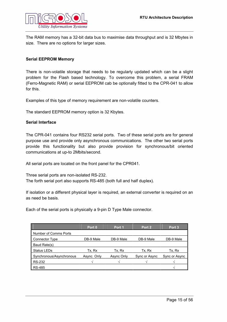
Serial Interface The CPR-041 contains four RS232 serial ports. Two of these serial ports are for general purpose use and provide only asynchronous communications. The other two serial ports provide this functionality but also provide provision for synchronous/bit oriented communications at up-to 2Mbits/second. All serial ports are located on the front panel for the CPR041. Three serial ports are non-isolated RS-232. The forth serial port also supports RS-485 (both full and half duplex). If isolation or a different physical layer is required, an external converter is required on an as need be basis. Each of the serial ports is physically a 9-pin D Type Male connector.
Port 0 Port 1 Port 2 Port 3 Number of Comms Ports Connector Type DB-9 Male DB-9 Male DB-9 Male DB-9 Male Baud Rate(s) Status LEDs Tx, Rx Tx, Rx Tx, Rx Tx, Rx Synchronous/Asynchronous Async Only Async Only Sync or Async Sync or Async RS-232 √ √ √ √ RS-485 √
RTU Architecture Description
Page 16 of 56
CAN-Bus Interface To allow for future expansion, a CAN-Bus interface has been provided on the CPR-041 module. CAN (Controller Area Network) Bus is a serial bus designed for networking smart devices with high data integrity in noisy environments. This will allow intelligent I/O modules to be connected to the CPR-041 and to reduce some of the low-level overhead of data collection. The CAN-Bus interface provided is CAN2.0B actively compliant and can be run at up to 1Mbit/s. The physical interface for the CAN-Bus is provided as per the ISO 11898 standard. The CAN-Bus interface will come from the rear of the CPR-041 through the DIN 41612C Body Connectors. No connectivity is provided for the CAN-bus at this stage.
FieldNet Interface The FieldNet interface is compatible with the CPR-021, with the following exceptions: • There is only one physical interface instead of two. • The FieldNet can be run at twice the speed of the older system. • The FieldNet interface is connected to the processor via DMA. For the CPR-041, the second FieldNet path has been removed. Redundancy is supplied via the optional redundant fibre optic communications method that provides the data link redundancy. The next generation of FieldNet controller is used in the CPR-041 which allows the data rate to be increased from 2.5MBits/Second to 5Mbits/Second. A DMA interface is provided in the CPR-041 to communicate with the FieldNet controller. The physical interface for the FieldNet is RS-485. This interface is isolated from the internal electronics via an isolating converter, which provides an isolation barrier of 500VDC.
Ethernet Interface The CPR-041 is provided with a 10/100Mbit/s Ethernet interface with DMA capability. The physical interface for the Ethernet is 100BaseT provided through a RJ-45 connector on the front panel of the CPR-041. If other physical interfaces are required (such as fibre optics) an external level converter is required.
RTU Architecture Description
Page 17 of 56
The Ethernet interface is isolated from the CPR-041 internal electronics via the isolation transformer used for the 100BaseT interface.
Backplane I/O Interface The CPR-041 provides an interface similar to the CPR-021 for the connection of standard XCell I/O modules through a back-plane connection at the rear of the module using two DIN 41612C Body connectors. The functionality of the interface is identical to the CPR-021 interface.
Front Panel Interface The front panel for the CPR-041 contains similar functionality to the front panel of the CPR-021. The following indications are provided: • Active LED • On-Line LED • 3 Digit Display • Matrix of 4 by 16 indications • Function Button • RxD and TxD for each serial channel • Link, Activity, A and B for the Ethernet port • On/Off switch
TCXO Provision The CPR-041 module has a provision to install a Temperature Compensated Crystal Oscillator onto the module to provide a more accurate time source for the operation of the clock in the module. The precision of the TCXO is better than ±2 PPM.
Power Supply The Power Supply is on-board the CPR-041 and has the following specifications:
REQUIREMENT Power Supply Range DC 18 – 72 VDC Power Supply Isolation 2.5KV AC RMS Power Consumption 7W Voltage Outputs +5V (internal use only)
+12V @ 400 mA (available through RS 232 port for external use) -12V @ 90 mA (available through RS 232 port for external use)
RTU Architecture Description
Page 18 of 56
An isolated power supply is provided for the FieldNet physical interface. This is provided via a small isolating power supply.
Software Interface The Software interface for the CPR-041 is the same as with all the other members of the XCell family. The software architecture is described later in this document.
Configuration The configuration of the CPR-041 is exactly the same as the configuration of the existing CPR-021. It is configured via one serial port or via the FieldNet network using Microsol Workbench.
RTU Architecture Description
Page 19 of 56
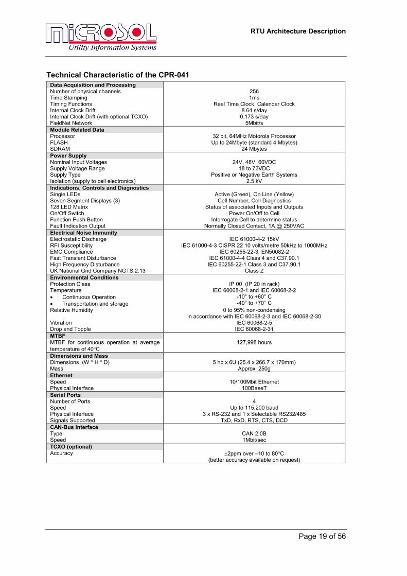
Technical Characteristic of the CPR-041 Data Acquisition and Processing Number of physical channels 256 Time Stamping 1ms Timing Functions Real Time Clock, Calendar Clock Internal Clock Drift 8.64 s/day Internal Clock Drift (with optional TCXO) 0.173 s/day FieldNet Network 5Mbit/s Module Related Data Processor 32 bit, 64MHz Motorola Processor FLASH Up to 24Mbyte (standard 4 Mbytes) SDRAM 24 Mbytes Power Supply Nominal Input Voltages 24V, 48V, 60VDC Supply Voltage Range 18 to 72VDC Supply Type Positive or Negative Earth Systems Isolation (supply to cell electronics) 2.5 kV Indications, Controls and Diagnostics Single LEDs Active (Green), On Line (Yellow) Seven Segment Displays (3) Cell Number, Cell Diagnostics 128 LED Matrix Status of associated Inputs and Outputs On/Off Switch Power On/Off to Cell Function Push Button Interrogate Cell to determine status Fault Indication Output Normally Closed Contact, 1A @ 250VAC Electrical Noise Immunity Electrostatic Discharge IEC 61000-4-2 15kV RFI Susceptibility IEC 61000-4-3 CISPR 22 10 volts/metre 50kHz to 1000MHz EMC Compliance IEC 60255-22-3, EN50082-2 Fast Transient Disturbance IEC 61000-4-4 Class 4 and C37.90.1 High Frequency Disturbance IEC 60255-22-1 Class 3 and C37.90.1 UK National Grid Company NGTS 2.13 Class Z Environmental Conditions Protection Class IP 00 (IP 20 in rack) Temperature • Continuous Operation • Transportation and storage
IEC 60068-2-1 and IEC 60068-2-2 -10° to +60° C -40° to +70° C
Relative Humidity 0 to 95% non-condensing in accordance with IEC 60068-2-3 and IEC 60068-2-30
Vibration IEC 60068-2-5 Drop and Topple IEC 60068-2-31 MTBF MTBF for continuous operation at average temperature of 40°C
127,998 hours
Dimensions and Mass Dimensions (W * H * D) 5 hp x 6U (25.4 x 266.7 x 170mm) Mass Approx. 250g Ethernet Speed 10/100Mbit Ethernet Physical Interface 100BaseT Serial Ports Number of Ports 4 Speed Up to 115,200 baud Physical Interface 3 x RS-232 and 1 x Selectable RS232/485 Signals Supported TxD, RxD, RTS, CTS, DCD CAN-Bus Interface Type CAN 2.0B Speed 1Mbit/sec TCXO (optional) Accuracy ±2ppm over –10 to 80°C
(better accuracy available on request)
RTU Architecture Description
Page 20 of 56
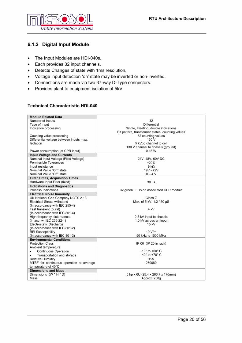
6.1.2 Digital Input Module • The Input Modules are HDI-040s. • Each provides 32 input channels. • Detects Changes of state with 1ms resolution. • Voltage input detection ‘on’ state may be inverted or non-inverted. • Connections are made via two 37-way D-Type connectors. • Provides plant to equipment isolation of 5kV
Technical Characteristic HDI-040
Module Related Data Number of Inputs 32 Type of Input Differential Indication processing Single, Fleeting, double indications
Bit pattern, transformer states, counting values Counting value processing 32 counting values Differential voltage between inputs max. 130 V Isolation 5 kVpp channel to cell 130 V channel to chassis (ground) Power consumption (at CPR input) 0.15 W Input Voltage and Currents Nominal Input Voltage (Field Voltage) 24V, 48V, 60V DC Permissible Tolerances ±20% Input resistance 9 kΩ Nominal Value “On” state 19V - 72V Nominal Value “Off” state 0 – 4 V Filter Times, Acquisition Times Hardware Input Filter (fixed) 30 µs Indications and Diagnostics Process Indications 32 green LEDs on associated CPR module Electrical Noise Immunity UK National Grid Company NGTS 2.13 Class Z Electrical Stress withstand (In accordance with IEC 255-4)
Max. of 5 kV, 1.2 / 50 µS
Fast transient (burst) (In accordance with IEC 801-4)
4 kV
High frequency disturbance (in acc. w. IEC 255-22-1)
2.5 kV input to chassis 1.0 kV across an input
Electrostatic Discharge (In accordance with IEC 801-2)
15 kV
RFI Susceptibility (In accordance with IEC 801-3)
10 V/m 50 kHz to 1000 MHz
Environmental Conditions Protection Class IP 00 (IP 20 in rack) Ambient temperature • Continuous Operation • Transportation and storage
-10° to +60° C -40° to +70° C
Relative Humidity 95% MTBF for continuous operation at average temperature of 40°C
270080
Dimensions and Mass Dimensions (W * H * D) 5 hp x 6U (25.4 x 266.7 x 170mm) Mass Approx. 250g
RTU Architecture Description
Page 21 of 56
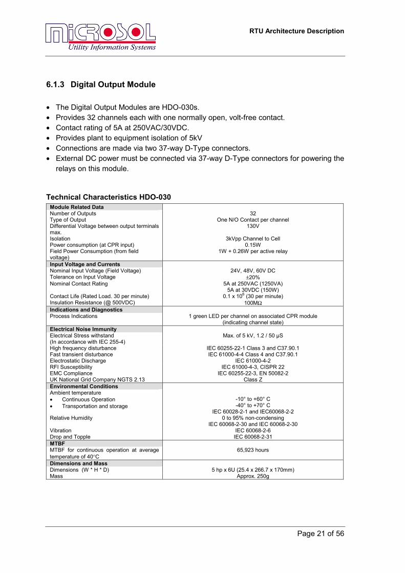
6.1.3 Digital Output Module • The Digital Output Modules are HDO-030s. • Provides 32 channels each with one normally open, volt-free contact. • Contact rating of 5A at 250VAC/30VDC. • Provides plant to equipment isolation of 5kV • Connections are made via two 37-way D-Type connectors. • External DC power must be connected via 37-way D-Type connectors for powering the
relays on this module.
Technical Characteristics HDO-030 Module Related Data Number of Outputs 32 Type of Output One N/O Contact per channel Differential Voltage between output terminals max.
130V
Isolation 3kVpp Channel to Cell Power consumption (at CPR input) 0.15W Field Power Consumption (from field voltage)
1W + 0.26W per active relay
Input Voltage and Currents Nominal Input Voltage (Field Voltage) 24V, 48V, 60V DC Tolerance on Input Voltage ±20% Nominal Contact Rating 5A at 250VAC (1250VA)
5A at 30VDC (150W) Contact Life (Rated Load. 30 per minute) 0.1 x 10⁶ (30 per minute) Insulation Resistance (@ 500VDC) 100MΩ Indications and Diagnostics Process Indications 1 green LED per channel on associated CPR module
(indicating channel state) Electrical Noise Immunity Electrical Stress withstand (In accordance with IEC 255-4)
Max. of 5 kV, 1.2 / 50 µS
High frequency disturbance IEC 60255-22-1 Class 3 and C37.90.1 Fast transient disturbance IEC 61000-4-4 Class 4 and C37.90.1 Electrostatic Discharge IEC 61000-4-2 RFI Susceptibility IEC 61000-4-3, CISPR 22 EMC Compliance IEC 60255-22-3, EN 50082-2 UK National Grid Company NGTS 2.13 Class Z Environmental Conditions Ambient temperature • Continuous Operation • Transportation and storage
-10° to +60° C -40° to +70° C
IEC 60028-2-1 and IEC60068-2-2 Relative Humidity 0 to 95% non-condensing
IEC 60068-2-30 and IEC 60068-2-30 Vibration IEC 60068-2-6 Drop and Topple IEC 60068-2-31 MTBF MTBF for continuous operation at average temperature of 40°C
65,923 hours
Dimensions and Mass Dimensions (W * H * D) 5 hp x 6U (25.4 x 266.7 x 170mm) Mass Approx. 250g
RTU Architecture Description
Page 22 of 56
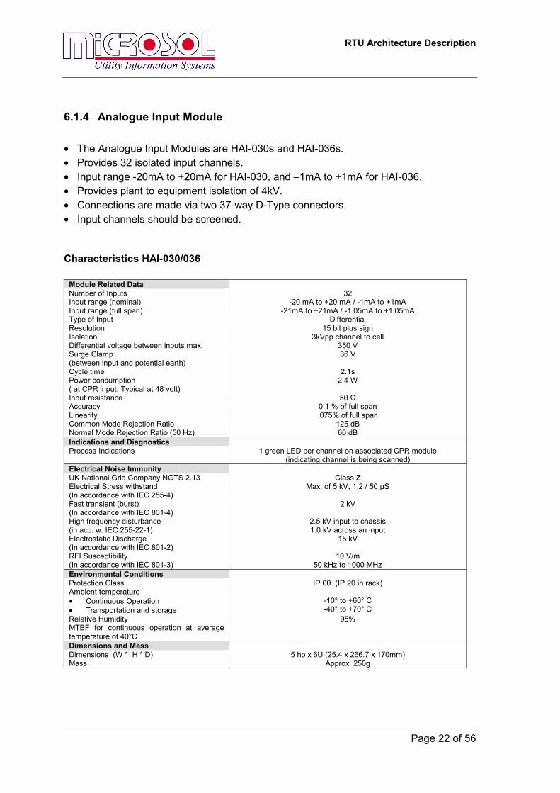
6.1.4 Analogue Input Module • The Analogue Input Modules are HAI-030s and HAI-036s. • Provides 32 isolated input channels. • Input range -20mA to +20mA for HAI-030, and –1mA to +1mA for HAI-036. • Provides plant to equipment isolation of 4kV. • Connections are made via two 37-way D-Type connectors. • Input channels should be screened.
Characteristics HAI-030/036
Module Related Data Number of Inputs 32 Input range (nominal) -20 mA to +20 mA / -1mA to +1mA Input range (full span) -21mA to +21mA / -1.05mA to +1.05mA Type of Input Differential Resolution 15 bit plus sign Isolation 3kVpp channel to cell Differential voltage between inputs max. 350 V Surge Clamp (between input and potential earth)
36 V
Cycle time 2.1s Power consumption ( at CPR input. Typical at 48 volt)
2.4 W
Input resistance 50 Ω Accuracy 0.1 % of full span Linearity .075% of full span Common Mode Rejection Ratio 125 dB Normal Mode Rejection Ratio (50 Hz) 60 dB Indications and Diagnostics Process Indications 1 green LED per channel on associated CPR module
(indicating channel is being scanned) Electrical Noise Immunity UK National Grid Company NGTS 2.13 Class Z Electrical Stress withstand (In accordance with IEC 255-4)
Max. of 5 kV, 1.2 / 50 µS
Fast transient (burst) (In accordance with IEC 801-4)
2 kV
High frequency disturbance (in acc. w. IEC 255-22-1)
2.5 kV input to chassis 1.0 kV across an input
Electrostatic Discharge (In accordance with IEC 801-2)
15 kV
RFI Susceptibility (In accordance with IEC 801-3)
10 V/m 50 kHz to 1000 MHz
Environmental Conditions Protection Class IP 00 (IP 20 in rack) Ambient temperature • Continuous Operation • Transportation and storage
-10° to +60° C -40° to +70° C
Relative Humidity 95% MTBF for continuous operation at average temperature of 40°C
Dimensions and Mass Dimensions (W * H * D) 5 hp x 6U (25.4 x 266.7 x 170mm) Mass Approx. 250g
RTU Architecture Description
Page 23 of 56
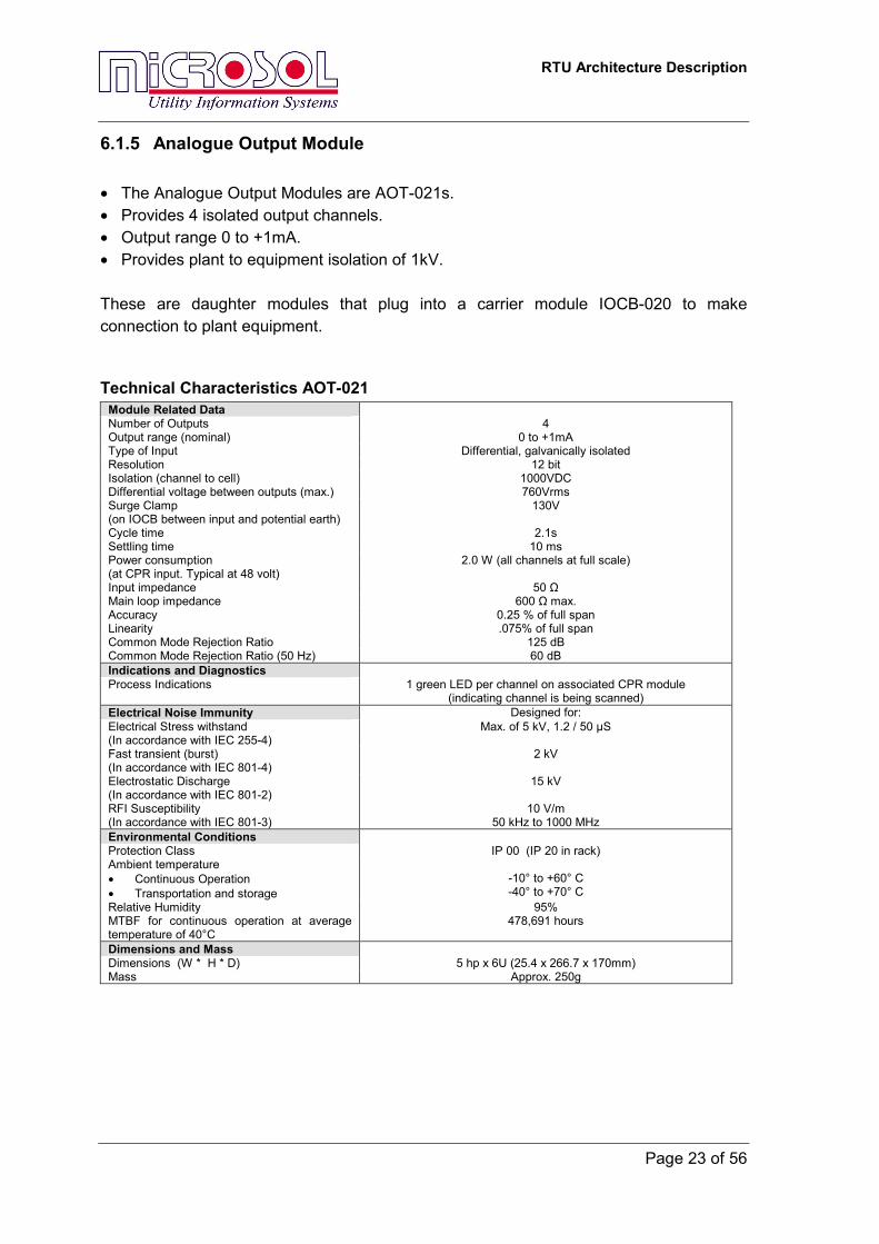
6.1.5 Analogue Output Module • The Analogue Output Modules are AOT-021s. • Provides 4 isolated output channels. • Output range 0 to +1mA. • Provides plant to equipment isolation of 1kV. These are daughter modules that plug into a carrier module IOCB-020 to make connection to plant equipment.
Technical Characteristics AOT-021 Module Related Data Number of Outputs 4 Output range (nominal) 0 to +1mA Type of Input Differential, galvanically isolated Resolution 12 bit Isolation (channel to cell) 1000VDC Differential voltage between outputs (max.) 760Vrms Surge Clamp (on IOCB between input and potential earth)
130V
Cycle time 2.1s Settling time 10 ms Power consumption (at CPR input. Typical at 48 volt)
2.0 W (all channels at full scale)
Input impedance 50 Ω Main loop impedance 600 Ω max. Accuracy 0.25 % of full span Linearity .075% of full span Common Mode Rejection Ratio 125 dB Common Mode Rejection Ratio (50 Hz) 60 dB Indications and Diagnostics Process Indications 1 green LED per channel on associated CPR module
(indicating channel is being scanned) Electrical Noise Immunity Designed for: Electrical Stress withstand (In accordance with IEC 255-4)
Max. of 5 kV, 1.2 / 50 µS
Fast transient (burst) (In accordance with IEC 801-4)
2 kV
Electrostatic Discharge (In accordance with IEC 801-2)
15 kV
RFI Susceptibility (In accordance with IEC 801-3)
10 V/m 50 kHz to 1000 MHz
Environmental Conditions Protection Class IP 00 (IP 20 in rack) Ambient temperature • Continuous Operation • Transportation and storage
-10° to +60° C -40° to +70° C
Relative Humidity 95% MTBF for continuous operation at average temperature of 40°C
478,691 hours
Dimensions and Mass Dimensions (W * H * D) 5 hp x 6U (25.4 x 266.7 x 170mm) Mass Approx. 250g
RTU Architecture Description
Page 24 of 56
6.1.6 Input Output Carrier Board • The Input Output Carrier Modules are IOCB-020s. • Provides plant connection to daughter modules (AOT-021). • Connections are made via one 37-way D-Type connector.
6.1.7 19 Inch Equipment Rack • The standard racks are RAK-040s. • 6U high to suit double height Eurocard modules. • Each supports up to 3 XCell units (CPR + 4 I/O modules) – Other configurations with
few I/O Modules are possible. • Power and FieldNet connections made to rear of racks.
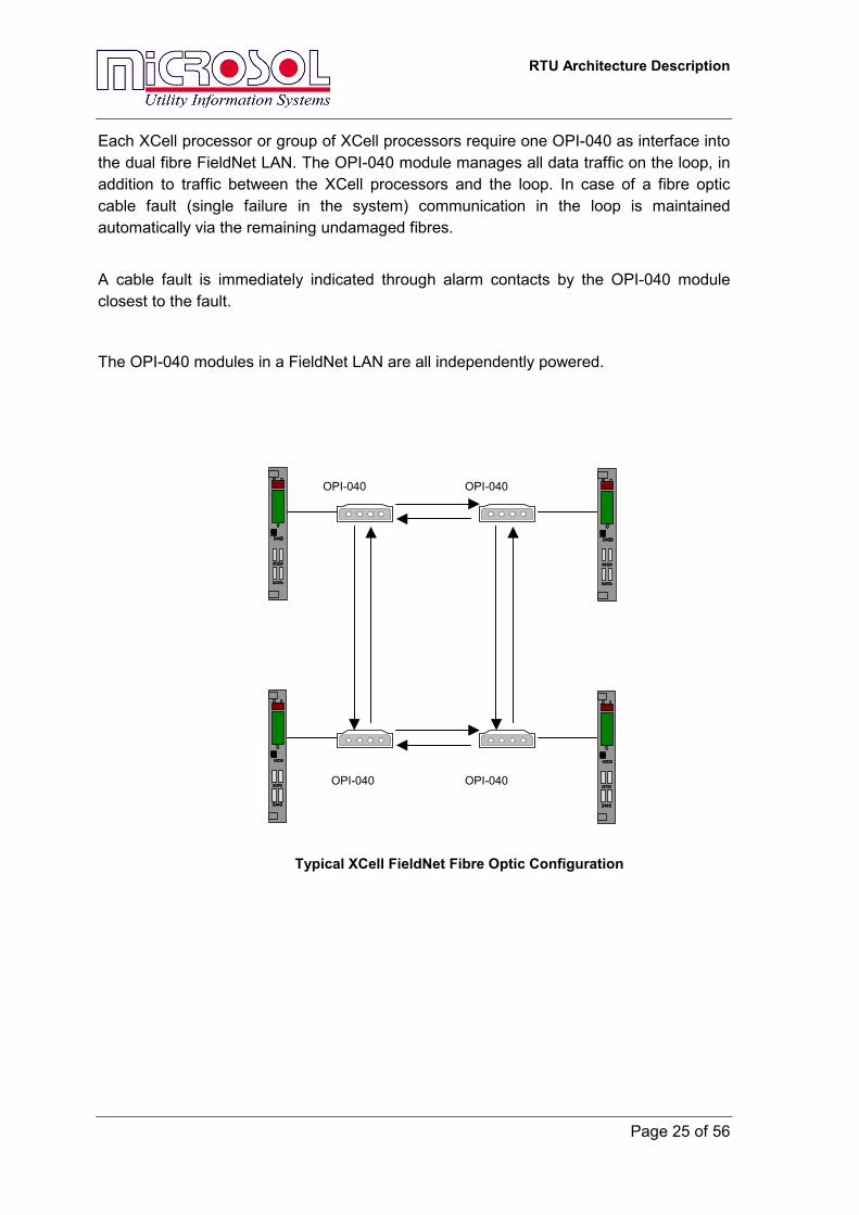
6.1.8 OPI-040 FieldNet Fibre Optic Interface • Dual Fibre Optic Interface • Redundant LAN Loop • Runs at up-to 10Mbits/Second • Loop Failure Alarm Indications • Loop Failure Alarm Contacts • Compact Unit • Single Point Failure does not break Communications The OPI-040 delivers a totally flexible solution for interfacing multiple XCell processor cells remotely in a distributed arrangement. This provides redundant communications paths via multi-mode fibre optic cables. The OPI-040 sets up a dual FieldNet LAN loop with communications going in opposite directions around the loop. In this way, if any section of the loop fails, every unit can still communicate with every other unit in the system. If one of the OPI-040 units fails, communications to that cell will fail, but the rest of the communications loop will operate unhindered. The OPI-040 allows the XCell network to be distributed up to a loop total length of 2km. Multiple XCell units can be connected together locally on the RS-485 physical layer and then connected to an OPI-040 for distribution outside of the cubicle.
RTU Architecture Description
Page 25 of 56
Each XCell processor or group of XCell processors require one OPI-040 as interface into the dual fibre FieldNet LAN. The OPI-040 module manages all data traffic on the loop, in addition to traffic between the XCell processors and the loop. In case of a fibre optic cable fault (single failure in the system) communication in the loop is maintained automatically via the remaining undamaged fibres.
A cable fault is immediately indicated through alarm contacts by the OPI-040 module closest to the fault.
The OPI-040 modules in a FieldNet LAN are all independently powered.
OPI-040 OPI-040
OPI-040 OPI-040
Typical XCell FieldNet Fibre Optic Configuration
RTU Architecture Description
Page 26 of 56
OPI-040 Technical Characteristics
XCell FieldNet Interface Number of FieldNet Ports 1 Channel Type of Interface RS 485 Two Wire twisted pair plus screen Data Transfer Rate 5 Mbit or 10 Mbit Line Termination 120 Ω provided
120 Ω termination to be provided at CPR processor Type of Connection Compression type screw terminal up to 2.5 mm² Fibre Optic Interface Number of Channels 2 TX and 2 RX Channels Fibre Interface 62.5/125 µm Multi-Mode, 820nm, GaAIAs LED Termination ST Type Connectors Transmitter Output Power Typically –12dBm @ 25 C° Receiver Input Sensitivity Typically –40dBm @ 25 C° Maximum Loop Distance and number of units
20 units @ total loop distance of 2 km
Maximum Distance between any OPI-040 units
1.5 km
Power Supply and Consumption Input Range 18 – 72 Vdc Power Consumption < 1.5W Isolation 3 kV Type of Connection Compression type screw terminal up to 2.5 mm²
Indications and Diagnostics
Process Indications 1 x Power On LED Indication 2 x Fibre Optics RX Failure LEDs
Standards
Radiated Emission EN 55 022 Class A (formerly CISPR –022)
Environmental Conditions
Protection Class IP 20 Ambient temperature • Continuous Operation • Transportation and storage
-10° to +60° C -40° to +70° C
Relative Humidity 95%
Dimensions and Mass
Dimensions (W * H * D) 128 x 74 x 47 mm Mass Approx. 250g
Installation
Mounting DIN Rail mounted
Alarm Status Outputs
Maximum 150 Vdc @ 50 mA Isolation 5 kv AC
RTU Architecture Description
Page 27 of 56
7 Input / Output Processing
7.1 Digital Inputs
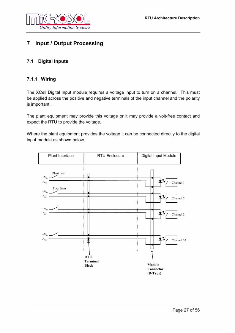
7.1.1 Wiring The XCell Digital Input module requires a voltage input to turn on a channel. This must be applied across the positive and negative terminals of the input channel and the polarity is important. The plant equipment may provide this voltage or it may provide a volt-free contact and expect the RTU to provide the voltage. Where the plant equipment provides the voltage it can be connected directly to the digital input module as shown below.
Channel 1
+Vin
-Vin
Channel 2
Channel 3
Channel 32
Plant Interface RTU Enclosure Digital Input Module
ModuleConnector(D-Type)
RTUTerminalBlock
Plant Item
Plant Item
+Vin
-Vin
+Vin
-Vin
+Vin
-Vin
RTU Architecture Description
Page 28 of 56
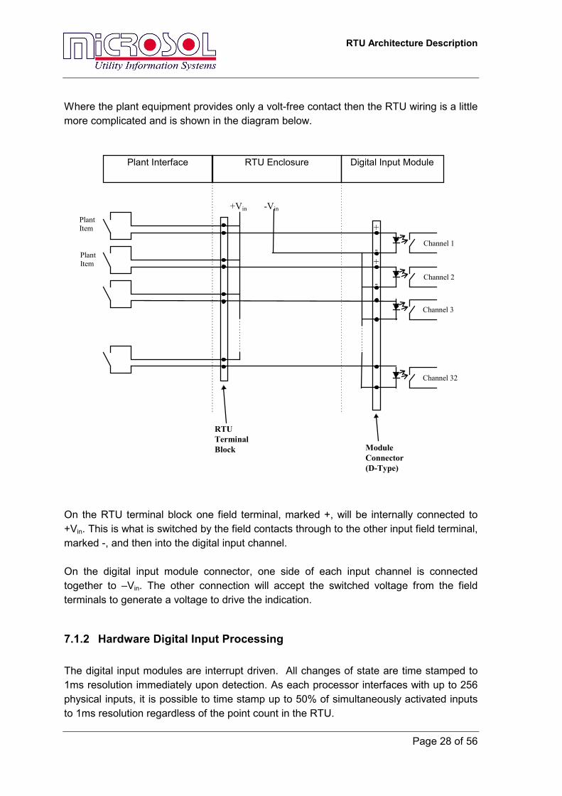
Where the plant equipment provides only a volt-free contact then the RTU wiring is a little more complicated and is shown in the diagram below.
+Vin -Vin
Plant Interface RTU Enclosure Digital Input Module
Channel 1
Channel 2
Channel 3
Channel 32
ModuleConnector(D-Type)
RTUTerminalBlock
PlantItem
PlantItem
-
+
-
+
On the RTU terminal block one field terminal, marked +, will be internally connected to +Vin. This is what is switched by the field contacts through to the other input field terminal, marked -, and then into the digital input channel. On the digital input module connector, one side of each input channel is connected together to –Vin. The other connection will accept the switched voltage from the field terminals to generate a voltage to drive the indication.
7.1.2 Hardware Digital Input Processing The digital input modules are interrupt driven. All changes of state are time stamped to 1ms resolution immediately upon detection. As each processor interfaces with up to 256 physical inputs, it is possible to time stamp up to 50% of simultaneously activated inputs to 1ms resolution regardless of the point count in the RTU.
RTU Architecture Description
Page 29 of 56
The channels on a digital input module can be used for different indication types; in particular, single input indications, double input indications, transformer tap positions, BCD inputs, etc. The only restriction is that multiple input indications should use consecutive input channels.
7.1.3 Single Digital Inputs Single digital inputs have a number of user configurable parameters, which provide enhanced functionality when configured. The following standard functionality is included: • An ON Filter Time (0-60 secs) and an OFF Filter Time (0-60 secs) can be configured
on a channel basis. These are the validation times that the input must be in the ON state or the OFF state before the transition is accepted as valid and notified to the remainder of the system.
• State inversion can be configured on a channel basis, which will invert the actual physical input state before notifying the remainder of the system.
• Manual Suppression (channel out of service) can be configured on a channel basis, and will inhibit any changes from being generated for the particular input when Manual Suppression is enabled.
• Automatic Suppression inhibits any input changes being generated if the number of changes detected within a specified time period exceeds the threshold value. This prevents a faulty channel that may be constantly oscillating from generating a continuous sequence of events. Refer to the section on Automatic Suppression for further details.
• Debounce Time (4-255 milliseconds). Provides the ability to filter relay contact bounce.
7.1.4 Double Digital Inputs Two consecutive digital input channels can be grouped together and treated as a double digital input. DDIs have a number of configurable parameters which provide enhanced functionality when configured. The following standard functionality is available • A Valid State Filter Time (0-60s) and an Invalid State Filter Time (0-60s) can be
configured on a double point basis. These are the times that the combined inputs must be in a Valid state (01 or 10) or the Invalid state (00 or 11) before the transition is accepted as valid and notified to the remainder of the system.
• State inversion can be configured on a double point basis to invert the valid states (01 and 10) before notifying the remainder of the system. Invalid states (11 and 00) are not inverted.
• Manual Suppression (channel out of service) can be configured on a double point basis.
RTU Architecture Description
Page 30 of 56
• DDI’s also have the facility for Automatic Suppression. This automatically inhibits any changes being generated if the number of changes detected within a specified time period exceeds the threshold value. This prevents a faulty channel that may be constantly oscillating from generating a continuous sequence of events. Automatic Suppression as well as suppression parameters are user selectable on a cell basis. Please refer to the section on Automatic Suppression for further details.
• Debounce Time (4-255 milliseconds). Provides the ability to filter relay contact bounce.
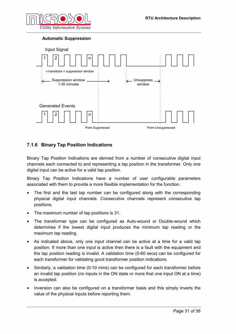
7.1.5 Automatic Suppression of Digital Inputs This is a self regulating feature that detects an excessive number of transitions on selected input channels within a short time period and inhibits these “problematic” channels from further reporting until the channels stabilise again. It is designed to suppress faulty digital inputs which may be oscillating and prevent them from generating an excessive number of meaningless events.
The following suppression parameters are user-configurable:
• Number of transitions (1-64).
• Time period (‘suppression window’ – 1 to 60 secs) during which transitions must occur before the point is suppressed.
• Time period (‘release window’ – 1 to 30 mins) during which the point must be stable before it is un-suppressed and the reporting of events is re-enabled.
SDI’s and DDI’s can be selected on a point basis to have automatic suppression enabled or disabled. This selection is a user configurable parameter.
Suppression events are generated when a point is suppressed and again when it is un-suppressed. These events are notified to the remainder of the system.
RTU Architecture Description
Page 31 of 56
Suppression window1-30 minutes
Unsuppresswindow
Point Suppressed
n transitions < suppression window
Point Unsuppressed
Automatic Suppression
Input Signal
1 2 n
1 2 n
Generated Events
7.1.6 Binary Tap Position Indications Binary Tap Position Indications are derived from a number of consecutive digital input channels each connected to and representing a tap position in the transformer. Only one digital input can be active for a valid tap position.
Binary Tap Position Indications have a number of user configurable parameters associated with them to provide a more flexible implementation for the function.
• The first and the last tap number can be configured along with the corresponding physical digital input channels. Consecutive channels represent consecutive tap positions.
• The maximum number of tap positions is 31.
• The transformer type can be configured as Auto-wound or Double-wound which determines if the lowest digital input produces the minimum tap reading or the maximum tap reading.
• As indicated above, only one input channel can be active at a time for a valid tap position. If more than one input is active then there is a fault with the equipment and the tap position reading is invalid. A validation time (0-60 secs) can be configured for each transformer for validating good transformer position indications.
• Similarly, a validation time (0-10 mins) can be configured for each transformer before an invalid tap position (no inputs in the ON state or more that one input ON at a time) is accepted.
• Inversion can also be configured on a transformer basis and this simply inverts the value of the physical inputs before reporting them.

RTU Architecture Description
Page 32 of 56
7.1.7 BCD Indications BCD Inputs are derived from a number of consecutive digital indications. The number of inputs depends on the number of BCD digits and any additional validity signals. XCell supports up to four BCD digits plus a strobe or validity input to signify that the digits are valid. BCD Inputs have a number of user configurable parameters associated with them: • The number of BCD digits can be configured from one digit (0-9) to four digits (0-
9999). Each digit requires four separate digital input channels. • A validation time (0-60 seconds) can be configured, before reporting a BCD value
change. This ensures that all digit changes have stabilised before reporting the new value. Alternatively, a validity signal can be used to determine when the BCD value is valid. On transition of the validity signal the BCD value is read and recorded.
• The 0 to 1 or 1 to 0 transition of the validity input can be selected for reading the BCD Inputs.
RTU Architecture Description
Page 33 of 56
7.2 Controls
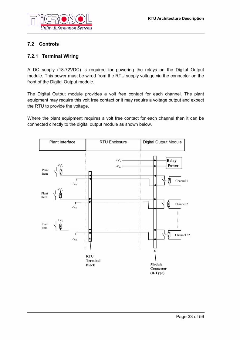
7.2.1 Terminal Wiring A DC supply (18-72VDC) is required for powering the relays on the Digital Output module. This power must be wired from the RTU supply voltage via the connector on the front of the Digital Output module. The Digital Output module provides a volt free contact for each channel. The plant equipment may require this volt free contact or it may require a voltage output and expect the RTU to provide the voltage. Where the plant equipment requires a volt free contact for each channel then it can be connected directly to the digital output module as shown below.
Plant Interface RTU Enclosure Digital Output Module
ModuleConnector(D-Type)
RTUTerminalBlock
Channel 1
PlantItem
+Vin
Channel 2
PlantItem
Channel 32
PlantItem
Relay Power
+Vin
+Vin
+Vin
-Vin
-Vin
-Vin
-Vin
RTU Architecture Description
Page 34 of 56
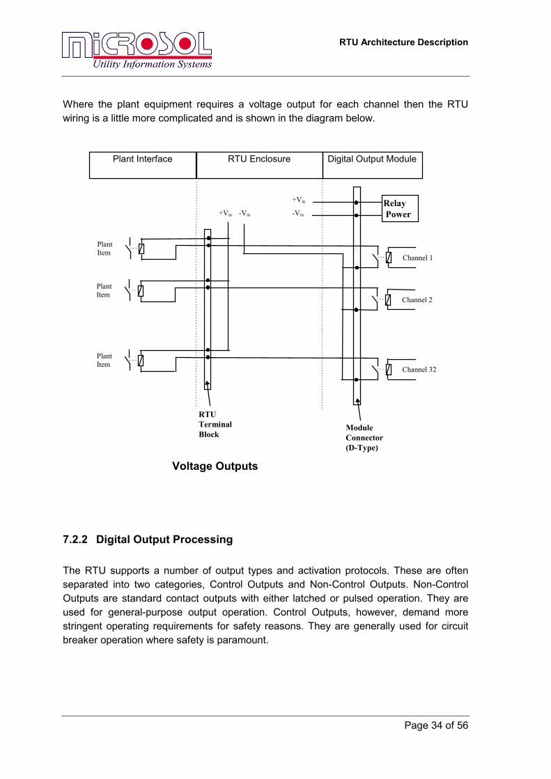
Where the plant equipment requires a voltage output for each channel then the RTU wiring is a little more complicated and is shown in the diagram below.
Plant Interface RTU Enclosure Digital Output Module
ModuleConnector(D-Type)
RTUTerminalBlock
+Vin -Vin
Channel 1
PlantItem
Channel 2
PlantItem
Channel 32
PlantItem
Voltage Outputs
Relay Power-Vin
+Vin
7.2.2 Digital Output Processing The RTU supports a number of output types and activation protocols. These are often separated into two categories, Control Outputs and Non-Control Outputs. Non-Control Outputs are standard contact outputs with either latched or pulsed operation. They are used for general-purpose output operation. Control Outputs, however, demand more stringent operating requirements for safety reasons. They are generally used for circuit breaker operation where safety is paramount.
RTU Architecture Description
Page 35 of 56
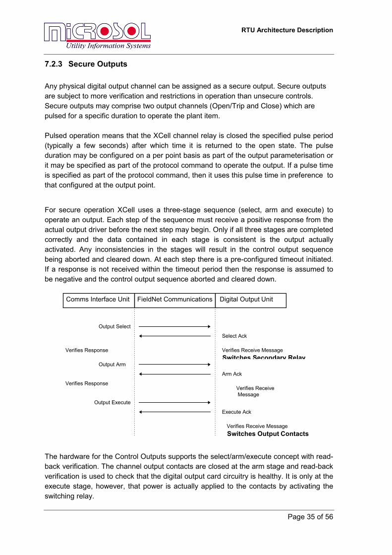
7.2.3 Secure Outputs Any physical digital output channel can be assigned as a secure output. Secure outputs are subject to more verification and restrictions in operation than unsecure controls. Secure outputs may comprise two output channels (Open/Trip and Close) which are pulsed for a specific duration to operate the plant item. Pulsed operation means that the XCell channel relay is closed the specified pulse period (typically a few seconds) after which time it is returned to the open state. The pulse duration may be configured on a per point basis as part of the output parameterisation or it may be specified as part of the protocol command to operate the output. If a pulse time is specified as part of the protocol command, then it uses this pulse time in preference to that configured at the output point. For secure operation XCell uses a three-stage sequence (select, arm and execute) to operate an output. Each step of the sequence must receive a positive response from the actual output driver before the next step may begin. Only if all three stages are completed correctly and the data contained in each stage is consistent is the output actually activated. Any inconsistencies in the stages will result in the control output sequence being aborted and cleared down. At each step there is a pre-configured timeout initiated. If a response is not received within the timeout period then the response is assumed to be negative and the control output sequence aborted and cleared down.
Comms Interface Unit FieldNet Communications Digital Output Unit
Output Select
Select Ack
Output Arm
Arm Ack
Output Execute
Execute Ack
Verifies Receive MessageSwitches Secondary Relay
Verifies Receive Message Switches Output Contacts
Verifies Receive Message
Verifies Response
Verifies Response
The hardware for the Control Outputs supports the select/arm/execute concept with read-back verification. The channel output contacts are closed at the arm stage and read-back verification is used to check that the digital output card circuitry is healthy. It is only at the execute stage, however, that power is actually applied to the contacts by activating the switching relay.
RTU Architecture Description
Page 36 of 56
Most XCell protocols for master station communications allow only one three stage command to be activated at any one time. Therefore if a control output command is received from the Master while a previous command is still currently in progress the second command will not be activated.
In addition, the target XCell unit activating the output will only allow one control output to be activated, or selected, in the XCell unit at any one time. A hardware jumper on the output module may also be set to indicate that it is a control output module and only one output is allowed to be active simultaneously.
Master station communications protocols that support secure control operations use XCell three stage sequence. Typically, a master station select operation returns to the master station the result of the select and arm stages, and the master station execute command results in an XCell three stage execute command.
7.2.3.1 Secure Outputs For Multiple Master Stations The XCell RTU has provisions for executing a number of requests from different master stations. The control sequence detailed above operates from a particular master station to the cell containing the digital output board it is attempting to control. When a secure control command from a different master station is received while a secure control sequence is in progress, the command is not used. Where a secure control has been executed, and the control is in the process of operating, select commands from any master station to the cell will fail. This prevents two controls from having closed contacts at the same time. These two measures ensure that only one secure control may be in sequence or operating at any time, regardless of the number of master stations communicating with the RTU. Note: not all controls in an RTU need to be made available to all master stations. Each slave protocol configuration may exclude controls a particular master station should not use, for increased security. In addition to these measures control arbitration may be implemented with an eXpress program. Each master station may be required to request permission from an eXpress program to do controls. The eXpress logic may then use any conditions present within the RTU to determine whether the master station should be granted permission to carry out controls. In this way a great number of schemes may be implemented, for instance to allow master stations to inhibit one another or to allow local operators to grant master stations permission.
7.2.4 Unsecured Outputs Unsecured, or direct, outputs are driven by a single stage operation and are not subjected to such authorisation conditions or operating checks and restrictions. These
RTU Architecture Description
Page 37 of 56
controls can also be configured for either latched or pulsed operation on a point by point basis. For pulsed outputs the length of the pulse can be configured on a point by point basis.
RTU Architecture Description
Page 38 of 56
7.3 Analogue Measurements
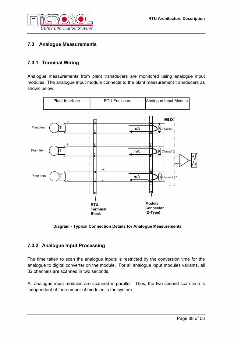
7.3.1 Terminal Wiring Analogue measurements from plant transducers are monitored using analogue input modules. The analogue input module connects to the plant measurement transducers as shown below:
Plant Interface RTU Enclosure Analogue Input Module
ModuleConnector(D-Type)
RTUTerminalBlock
A
D
+-
RPlant Item
+
-
+
-
+
-T
+
-mA Channel 2
Diagram - Typical Connection Details for Analogue Measurements
R Channel 1Plant Item
+
-
+
-
+
-T
+
-
MUX
mA
R Channel 32Plant Item
+
-
+
-
+
-T
+
-mA
7.3.2 Analogue Input Processing The time taken to scan the analogue inputs is restricted by the conversion time for the analogue to digital converter on the module. For all analogue input modules variants, all 32 channels are scanned in two seconds. All analogue input modules are scanned in parallel. Thus, the two second scan time is independent of the number of modules in the system.
RTU Architecture Description
Page 39 of 56
7.3.3 Analogue Input Measurements The nature of analogue signals gives rise to a situation where the communication links may become saturated if all analogue changes are recorded and transmitted by the system. To overcome this, some sort of analogue filtering is required. If the filtering level is too high, important information may be lost. Similarly, if it is too low, then the system may be flooded with too much information and lead to performance degradation. Therefore choosing the correct filter level is important. XCell supports a delta (or deadband) value for each analogue input to filter the value of the analogue signal obtained from the analogue module. The analogue value must change by more than the delta value before the new value is accepted and reported. The delta value is configured as a percentage of the total range of the analogue point. It is user configurable on a point by point basis. This delta value is applied to the value obtained from the analogue module and filters transmission within the XCell system
7.3.4 Analogue TAPS Analogue Tap Position Indications are derived from a single analogue input channel where the input current is directly proportional to the Tap Position. Analogue tap position indications have a number of user configurable parameters associated with them to provide a more flexible implementation for the function.
• The start tap number can be configured along with the corresponding physical analogue input current. Similarly, the maximum tap number (1-31) can be configured along with its corresponding physical analogue input current.
• In addition, a validation deadband can be configured for the transformer inputs. This is the allowed deviation around each valid tap position within which the value is still validated. If the transducer reading is outside the allowed deadband then the tap position is set to zero to indicate an invalid reading. The deadband is configured as a percentage of the incremental tap step.
RTU Architecture Description
Page 40 of 56
7.4 Analogue Outputs
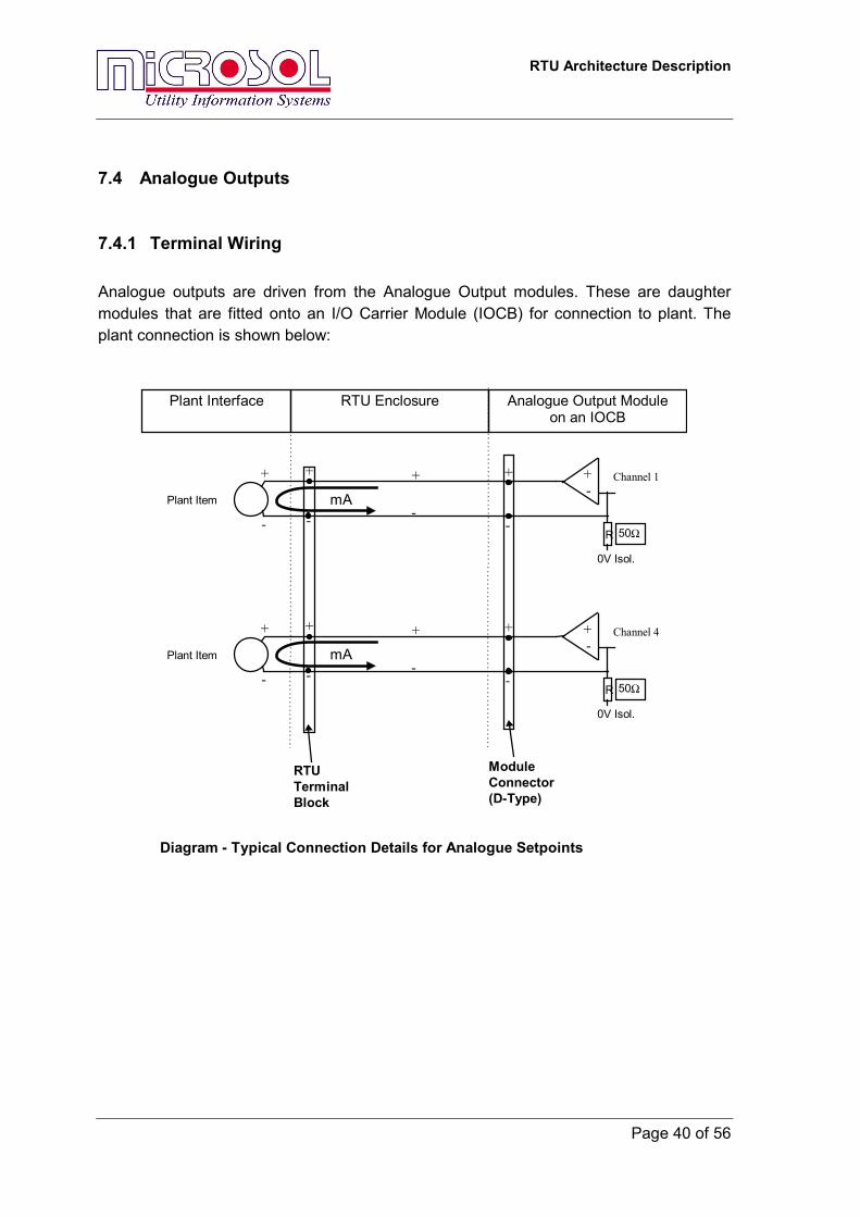
7.4.1 Terminal Wiring Analogue outputs are driven from the Analogue Output modules. These are daughter modules that are fitted onto an I/O Carrier Module (IOCB) for connection to plant. The plant connection is shown below:
Plant Interface RTU Enclosure Analogue Output Moduleon an IOCB
ModuleConnector(D-Type)
RTUTerminalBlock
Diagram - Typical Connection Details for Analogue Setpoints
+
-
+-
R
mAChannel 1+
-
+
-Plant Item
+
-
0V Isol.
50Ω
+
-
+-
R
mAChannel 4+
-
+
-Plant Item
+
-
0V Isol.
50Ω
RTU Architecture Description
Page 41 of 56
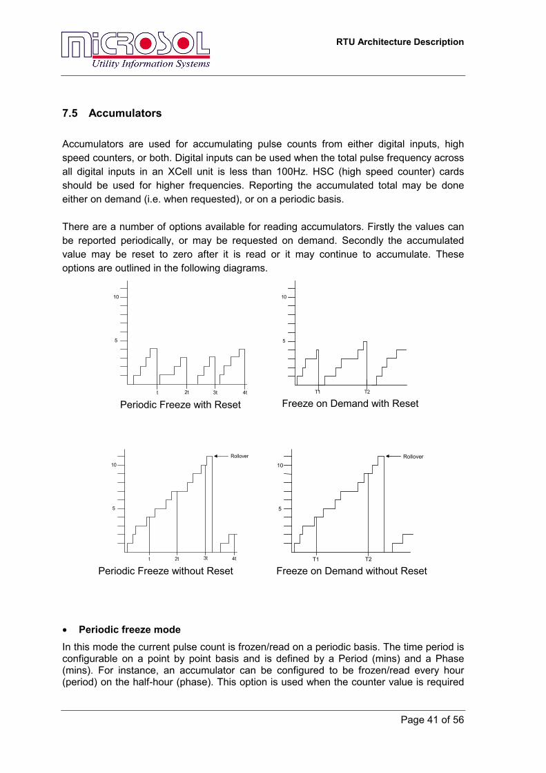
7.5 Accumulators Accumulators are used for accumulating pulse counts from either digital inputs, high speed counters, or both. Digital inputs can be used when the total pulse frequency across all digital inputs in an XCell unit is less than 100Hz. HSC (high speed counter) cards should be used for higher frequencies. Reporting the accumulated total may be done either on demand (i.e. when requested), or on a periodic basis. There are a number of options available for reading accumulators. Firstly the values can be reported periodically, or may be requested on demand. Secondly the accumulated value may be reset to zero after it is read or it may continue to accumulate. These options are outlined in the following diagrams.
• Periodic freeze mode In this mode the current pulse count is frozen/read on a periodic basis. The time period is configurable on a point by point basis and is defined by a Period (mins) and a Phase (mins). For instance, an accumulator can be configured to be frozen/read every hour (period) on the half-hour (phase). This option is used when the counter value is required
10
5
t 3t2t 4t Periodic Freeze with Reset
10
5
T1 T2 Freeze on Demand with Reset
10
5
t 2t 3t 4t
Rollover
Periodic Freeze without Reset
10
5
T1 T2
Rollover
Freeze on Demand without Reset

RTU Architecture Description
Page 42 of 56
over an accurate period of time, which may not be the case for report by master station command.
• Freeze-on-demand mode
In this mode a copy of the current pulse count is frozen/read on demand by a Master Station command. This command may be received at any time and multiple master stations may act as sources for counter commands.
• Freeze with reset In this mode, when the accumulator reports its total, the accumulator’s running value is reset to zero, and the next accumulator period begins.
• Freeze without reset In this mode, the accumulator reports its total value, but continues to accumulate the value without resetting the running value.
RTU Architecture Description
Page 43 of 56
8 RTU Diagnostic Indications In order for the master station to monitor the RTU itself, a number of indications are available which do not relate to physical IO. One of these indications is the unit status digital point. There is one of these points for each processor in a configuration, and the point indicates to a master station that a processor is on the network and operating normally. Each IO Card also has indications for normal operation. The IO Slot Status points indicate failure of IO hardware to a master station as a digital point. To configure these points, refer to the configuration tool documentation. Master communications protocols to other RTUs also offer health indications. For each remote device, a digital point is available to indicate correct communications. These points may be named communications status points or IED points, please refer to the protocol documentation.
RTU Architecture Description
Page 44 of 56
9 Time Synchronisation The RTU time must be referenced to some master clock, typically located at the master station. Normally, this time is sent to the RTU from the master station using a communications protocol that supports time synchronisation messages. The synchronisation process typically compensates for the transmission delays calculated according to the communications channel used and the protocol specification. The RTU may then use this time internally to timestamp IO events. Most communications protocols have configuration options for allowing the time synchronisation process to take place. They may always allow or disallow time commands, or they may allow commands only once a local clock has failed. Redundant RTU configurations or multiple master station configurations may have broader schemes. If the time synchronisation commands are to be used, the communications interface processor will set its reference time from the control centre via the protocol. In turn, the lowest unit number in a network will have its internal clock updated from the communications processor. This lowest unit number then becomes the time master for the RTU, responsible for synchronising the time in other XCell processors in the RTU every six seconds using the FieldNet network. As an alternative to the communications protocol, a GPS clock may be serially connected to a XCell processor. This processor typically receives a time telegram every minute, which it uses to synchronise the RTU with a higher accuracy than can be achieved with a communications protocol.
RTU Architecture Description
Page 45 of 56
10 FieldNet The FieldNet highway is the basic inter-cell communications link. This is a 5Mb link that incorporates very sophisticated error checking and recovery in its communications protocol. The high data rate ensures a consistently high system throughput. Within an RTU cabinet the FieldNet highway is generally connected using copper connections. Within an equipment rack these connections are pre-wired as part of the rack assembly. All racks should be connected in series, and FieldNet connections are available at both ends of the equipment racks to permit this. Terminating resistors are fitted at the extremities of the both highways for proper communications. The copper highway can be used to a maximum of 60m. The OPI-040 module is used to extend the FieldNet highways beyond a cabinet, using two fibre pairs as described in section 6.1.8 above. Units are automatically connected to the FieldNet highway when the modules are inserted into the equipment racks. Units can be added or removed from the RTU without any FieldNet re-configuration on the part of the user. This allows for simple repair procedures in the event of a cell failure.
RTU Architecture Description
Page 46 of 56
11 XCell Software Structure
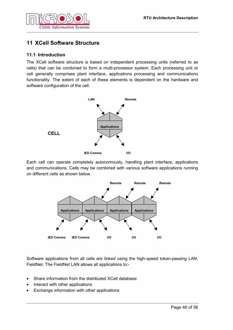
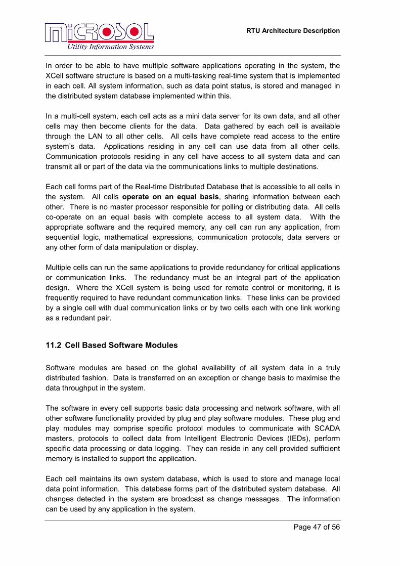
11.1 Introduction The XCell software structure is based on independent processing units (referred to as cells) that can be combined to form a multi-processor system. Each processing unit or cell generally comprises plant interface, applications processing and communications functionality. The extent of each of these elements is dependent on the hardware and software configuration of the cell. Each cell can operate completely autonomously, handling plant interface, applications and communications. Cells may be combined with various software applications running on different cells as shown below.
Software applications from all cells are linked using the high-speed token-passing LAN, FieldNet. The FieldNet LAN allows all applications to:-
• Share information from the distributed XCell database • Interact with other applications • Exchange information with other applications
Remote
IED Comms I/O
LAN
Applications
CELL
Applications
Remote
Applications
Remote
ApplicationsApplications
IED Comms IED Comms I/O I/O I/O
Remote
RTU Architecture Description
Page 47 of 56
In order to be able to have multiple software applications operating in the system, the XCell software structure is based on a multi-tasking real-time system that is implemented in each cell. All system information, such as data point status, is stored and managed in the distributed system database implemented within this. In a multi-cell system, each cell acts as a mini data server for its own data, and all other cells may then become clients for the data. Data gathered by each cell is available through the LAN to all other cells. All cells have complete read access to the entire system’s data. Applications residing in any cell can use data from all other cells. Communication protocols residing in any cell have access to all system data and can transmit all or part of the data via the communications links to multiple destinations. Each cell forms part of the Real-time Distributed Database that is accessible to all cells in the system. All cells operate on an equal basis, sharing information between each other. There is no master processor responsible for polling or distributing data. All cells co-operate on an equal basis with complete access to all system data. With the appropriate software and the required memory, any cell can run any application, from sequential logic, mathematical expressions, communication protocols, data servers or any other form of data manipulation or display. Multiple cells can run the same applications to provide redundancy for critical applications or communication links. The redundancy must be an integral part of the application design. Where the XCell system is being used for remote control or monitoring, it is frequently required to have redundant communication links. These links can be provided by a single cell with dual communication links or by two cells each with one link working as a redundant pair.
11.2 Cell Based Software Modules Software modules are based on the global availability of all system data in a truly distributed fashion. Data is transferred on an exception or change basis to maximise the data throughput in the system. The software in every cell supports basic data processing and network software, with all other software functionality provided by plug and play software modules. These plug and play modules may comprise specific protocol modules to communicate with SCADA masters, protocols to collect data from Intelligent Electronic Devices (IEDs), perform specific data processing or data logging. They can reside in any cell provided sufficient memory is installed to support the application. Each cell maintains its own system database, which is used to store and manage local data point information. This database forms part of the distributed system database. All changes detected in the system are broadcast as change messages. The information can be used by any application in the system.
RTU Architecture Description
Page 48 of 56
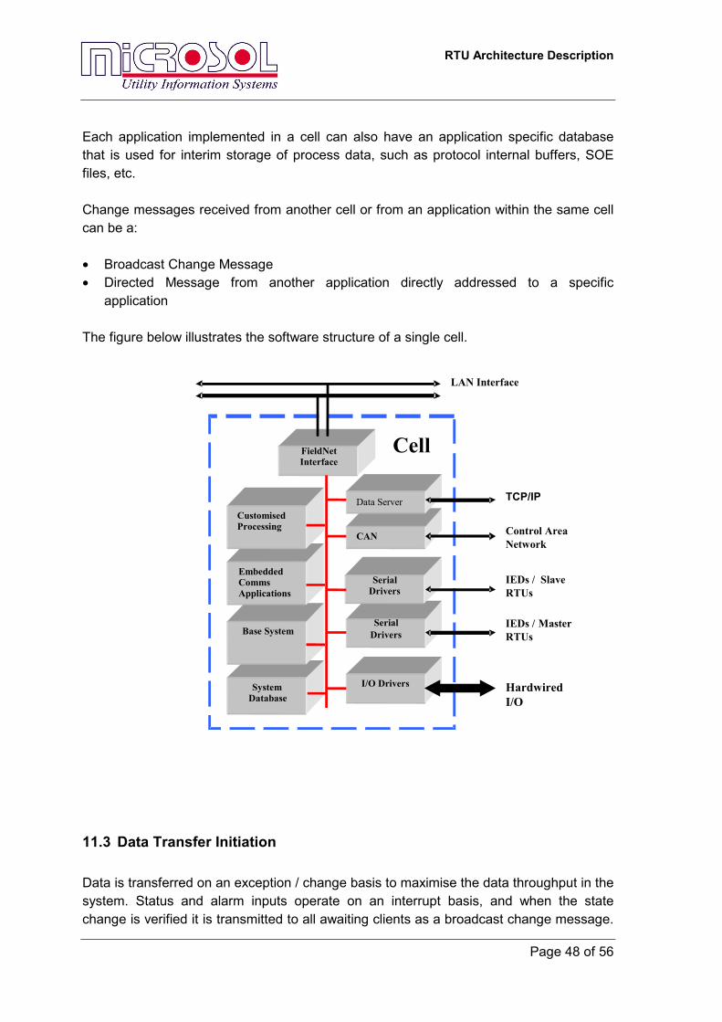
Each application implemented in a cell can also have an application specific database that is used for interim storage of process data, such as protocol internal buffers, SOE files, etc. Change messages received from another cell or from an application within the same cell can be a: • Broadcast Change Message • Directed Message from another application directly addressed to a specific
application The figure below illustrates the software structure of a single cell.
11.3 Data Transfer Initiation Data is transferred on an exception / change basis to maximise the data throughput in the system. Status and alarm inputs operate on an interrupt basis, and when the state change is verified it is transmitted to all awaiting clients as a broadcast change message.
SystemDatabase
Base System
EmbeddedCommsApplications
CustomisedProcessing
SerialDrivers
SerialDrivers
Cell
I/O Drivers
FieldNetInterface
HardwiredI/O
IEDs / MasterRTUs
TCP/IP
LAN Interface
CAN Control AreaNetwork
Data Server
IEDs / SlaveRTUs

RTU Architecture Description
Measured / analogue values are scanned on a continuous basis, and when a value has changed by more than the configured deadband, is it transmitted to the clients. Data from IEDs is polled on a continuous basis, and when new values are detected they too are transmitted to awaiting clients.
11.4 Peer to Peer Communications FieldNet LAN supports full peer to peer communications between cells. An application on one cell can communicate with an application on any other cell. The FieldNet LAN is a communications channel that will carry any type of data. It is not simply an I/O bus, but rather it can transfer I/O data, data files, configuration files, or any data format required for the site application. The LAN can even be used as a communications pipe between two serial ports, where data received on a serial port on one cell can be transmitted on a serial port on the other cell. This mechanism is used for IED configuration or IED file analysis from a central HMI. The IED software is run on the HMI connected to the serial port of one cell and the data echoed out the serial port connected to the IEDs as shown below.
IED Software
IED Configuration
Communications
C
IED Files
onfiguration
I/O
Files
Downloaded ApplicationsPage 49 of 56
Control Commands
Data Files
RTU Architecture Description
Page 50 of 56
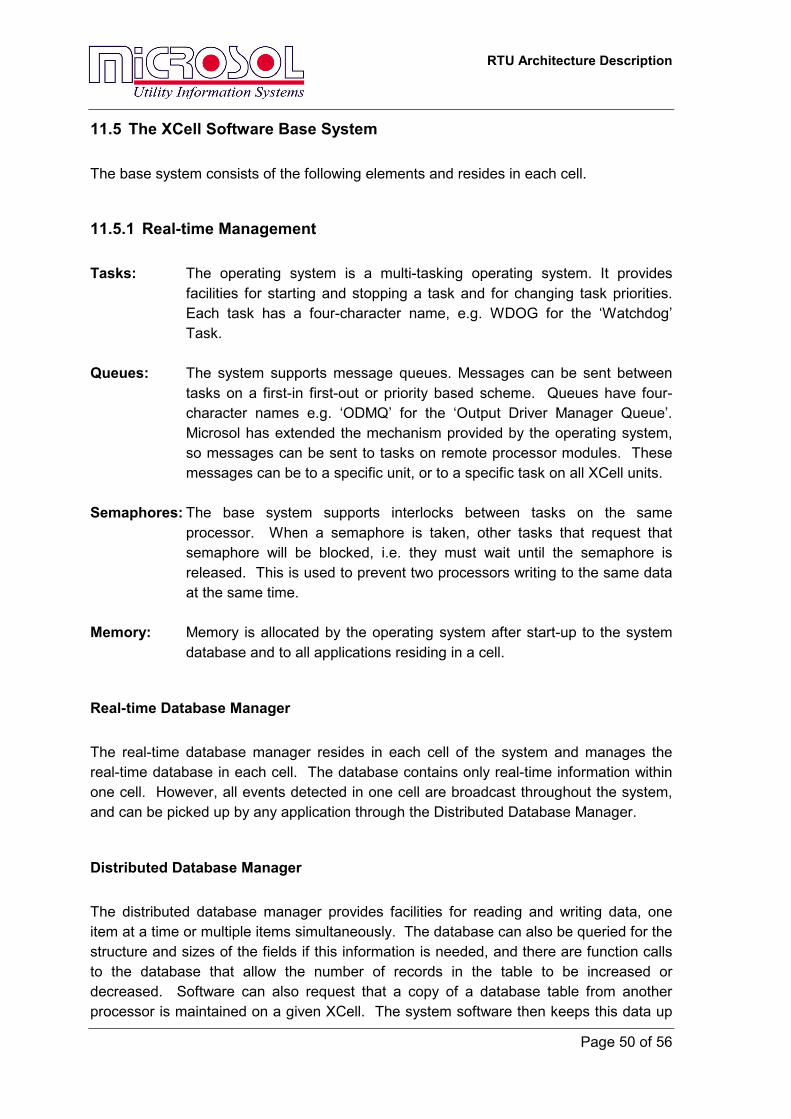
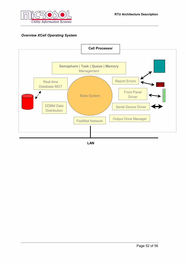
11.5 The XCell Software Base System The base system consists of the following elements and resides in each cell.
11.5.1 Real-time Management Tasks: The operating system is a multi-tasking operating system. It provides
facilities for starting and stopping a task and for changing task priorities. Each task has a four-character name, e.g. WDOG for the ‘Watchdog’ Task.
Queues: The system supports message queues. Messages can be sent between
tasks on a first-in first-out or priority based scheme. Queues have four-character names e.g. ‘ODMQ’ for the ‘Output Driver Manager Queue’. Microsol has extended the mechanism provided by the operating system, so messages can be sent to tasks on remote processor modules. These messages can be to a specific unit, or to a specific task on all XCell units.
Semaphores: The base system supports interlocks between tasks on the same
processor. When a semaphore is taken, other tasks that request that semaphore will be blocked, i.e. they must wait until the semaphore is released. This is used to prevent two processors writing to the same data at the same time.
Memory: Memory is allocated by the operating system after start-up to the system
database and to all applications residing in a cell.
Real-time Database Manager The real-time database manager resides in each cell of the system and manages the real-time database in each cell. The database contains only real-time information within one cell. However, all events detected in one cell are broadcast throughout the system, and can be picked up by any application through the Distributed Database Manager.
Distributed Database Manager The distributed database manager provides facilities for reading and writing data, one item at a time or multiple items simultaneously. The database can also be queried for the structure and sizes of the fields if this information is needed, and there are function calls to the database that allow the number of records in the table to be increased or decreased. Software can also request that a copy of a database table from another processor is maintained on a given XCell. The system software then keeps this data up
RTU Architecture Description
Page 51 of 56
to date with data elsewhere on the system.
Serial Device Driver The Serial Device Driver provides a software interface to the serial ports. The application configuration tables can set serial port parameters and send and receive data.
The Front Panel Driver The Front Panel Driver provides a software interface for displaying data on the front panel and for reading the state of the function button on the front panel.
Error Handling Each error occurring in the system is both displayed on the front panel, and logged in the system error log file, which can be viewed using Microsol Workbench. Application and run-time errors will suspend applications causing the error. This will affect a single cell only as long as the application is not a distributed software application.
Output Drive Manager Commands driving digital and analogue outputs are not broadcast in the system. Instead, the messaging system is used to communicate with the output drive manager on a particular cell. Commands are queued by the output drive manager and outputs are operated in sequential order. Single and three stage commands are possible. Depending on module hardware settings, either a single command or multiple commands can be executed at the same time in the system.
RTU Architecture Description
Page 52 of 56
Overview XCell Operating System
Base System
Semaphore | Task | Queue | Memory Management
Real-time Database MGT
Serial Device Driver
FieldNet Network
DDBM Data Distribution
Output Drive Manager
Front Panel Driver
Report Errors
Log
nEt
Cell Processor
LAN
RTU Architecture Description
Page 53 of 56
11.5.2 Database Management
System Start-up Starting up a multi-processor system is different to single processor system. The main difference is that applications that depend on information from another cell cannot start without the other cell being active. During the start-up procedure, all applications in the system, including the base I/O drivers, perform a “Full Update” of the system, which allows each application to set database points such as mapped inputs to their current state. A full update begins 40 seconds after start-up. However, in order to allow enough time for powering up all cells in a system, applications such as slave protocols often have a start-up delay of up to 1 minute. This allows the system to start all other applications, and to establish the system database so slave protocols may update their own internal protocol database.
System Failure Two categories of failures are defined: • Local cell failure • Total system failure A local cell failure is restricted to a single cell or several cells in the system. The consequences of a local cell failure are restricted to the affected cells and some information to other cells might not be available. An application that is still running may stop itself due to the loss of external data, or continue to operate with some error responses to other applications or to a master station through the serial I/O driver.
After recovery from a local failure, a cell will cause the execution of a full update before commencing full operation in the system.
The XCell includes a hardware watchdog that will reset the effected XCell in the event of a failure of the application software or the hardware. Once again , the full update mechanism will ensure the cell will perform a full update when returning to normal operation.
RTU Architecture Description
Page 54 of 56
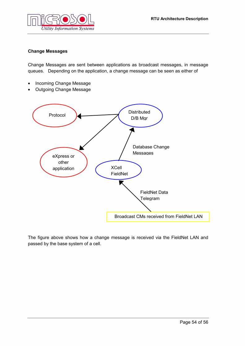
Change Messages Change Messages are sent between applications as broadcast messages, in message queues. Depending on the application, a change message can be seen as either of • Incoming Change Message • Outgoing Change Message The figure above shows how a change message is received via the FieldNet LAN and passed by the base system of a cell.
Distributed D/B Mgr
XCell FieldNet
Broadcast CMs received from FieldNet LAN
Database Change Messages
FieldNet Data Telegram
Protocol
eXpress or other
application
RTU Architecture Description
Page 55 of 56
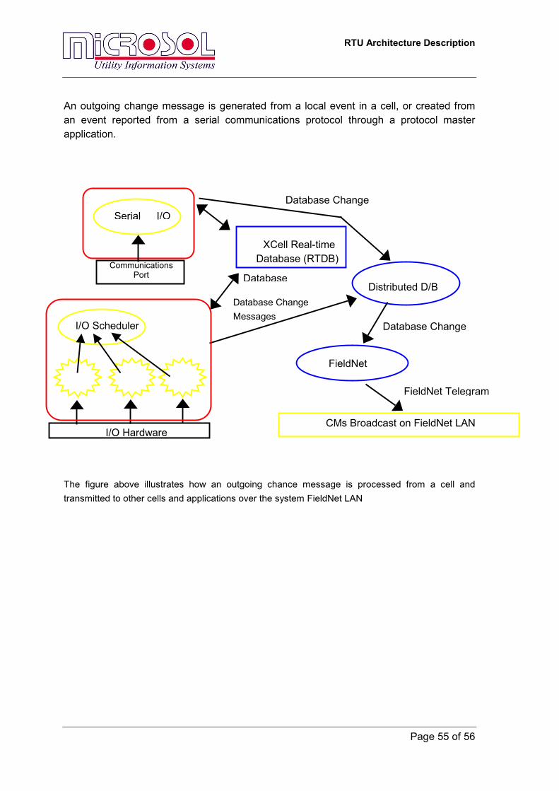
An outgoing change message is generated from a local event in a cell, or created from an event reported from a serial communications protocol through a protocol master application.
The figure above illustrates how an outgoing chance message is processed from a cell and transmitted to other cells and applications over the system FieldNet LAN
XCell Real-time Database (RTDB))
I/O Scheduler
Distributed D/B
FieldNet
CMs Broadcast on FieldNet LAN I/O Hardware
Database
Database Change Messages
Database Change
FieldNet Telegram
Serial I/ODatabase Change
Communications Port
RTU Architecture Description
Page 56 of 56
11.5.3 Software Application Implementation The XCell software system differentiates between three different application types: → Slave Protocol Application → Master Protocol Application → Data Processing Utility The following sections describe the implementation of all three software application types.
11.5.4 Slave Protocol Application A slave application emulates a communications protocol representing the slave or interrogated device in a master/slave system. Typically, the application only acts when the master device requests information. However, more sophisticated protocols such as the DNP3.0 or IEC 870-5-101 protocols provide for the slave to initiate communications and the XCell supports this. The slave application will consist of one or more tasks. The slave protocol performs the following functions • All received message from the master station a checked to ensure they are valid
(contain no transmission errors) and addressed to this device • Process requests for data (scanned or event) and send the data with the appropriate
protocol format. • Process control requests from the master station and operate associated controls via
the Output Drive Manager. To ensure the slave can respond to master station responses fast enough local event and analogue information is converted to the correct format and buffered in the cell.
RTU Architecture Description
Page 57 of 56
11.5.5 Master Protocol Application A master protocol application is responsible for polling data from a satellite device, this is usually a Intelligent Electronic Device (IED) such as a protection device or analogue meter. It may also be a RTU. The application schedules all data transaction and information exchange as master device, that is the XCell acts as a master station. The database of this application creates an “image” of all external RTUs connected to the application. The database and the associated events are distributed around the RTU in the same way that local event data is sent. Control commands are initiated and sent to the external devices by the master applications whenever a valid incoming change message is received from the base system. Events reported back from the external devices are broadcast or sent as an outgoing change message to the XCell base system. These change messages can be used by other applications for reporting to their master applications, etc.
11.5.6 Process / Logic Application In contrast to a slave or master application, an embedded process application normally performs logic or control functions based on the state of database points. Generally it will accept change message from the database and process then to produce the data in a new format or date type.


![[ Fontes para notebooks ] Microsol NotePower...Microsol NP90 Mais potência para seu notebook A NP90 é a fonte universal da linha Microsol que é ideal para notebooks de maior potência,](https://img.pdfslide.net/doc/110x75/5e3e8700c2555069b7126bc7/-fontes-para-notebooks-microsol-notepower-microsol-np90-mais-potncia-para.jpg)