Embed Size (px)
Citation preview
1
PROJECT REPORT ONPRODUCTION ENGINEERING DEPARTMENT-CS
SUBMITTED BY:-SWAPNIL SRIVASTAVA
(1203340170)B.Tech (ME) 2012-2016
UNDER THE GUIDENCE OF:-
Mr. MAYUR GANDHI(-TCF Logistics Centre)
TATA MOTORS LTD. LUCKNOW
Raj Kumar Goel Institute of Technology (UPTU), Ghaziabad
TATA MOTORS LTD, LUCKNOW
2Contents1. Acknowledgement
2. Abstract
3. Industry Profile - TATA Motors
4. TATA Motors - Lucknow Plant
5. Productivity Service Department (PSD) department
6. What Is Production Engineering?
7. Production Engineering department- TATA
8. Vision, Mission & Core Values
9. PROJECT
10. Learning
3AbstractThe title of my project is “Production Engineering Department”. This is basically a case study on the PE Department of TATA motors which is an important part of any industry. Not only in TATA Motors but in any industry either manufacturing or assembly all for the seamless working require the PE Department which creates all the fixtures and templates for any department or even any other plant. Production engineering is a combination of manufacturing technology with management science. A production engineer typically has a wide knowledge of engineering practices and is aware of the management challenges related to production. The goal is to accomplish the production process in the smoothest, most-judicious and most-economic way. In industry, once the design is realized, production engineering concepts regarding work-study, ergonomics, operation research, manufacturing management, materials management, production planning, etc., play important roles in efficient production processes. These deal with integrated design and efficient planning of the entire manufacturing system, which is becoming increasingly complex with the emergence of sophisticated production methods and control systems.This department is not only needed but in actual without this the functioning of any plant would become a lot difficult. This is very necessary and useful.
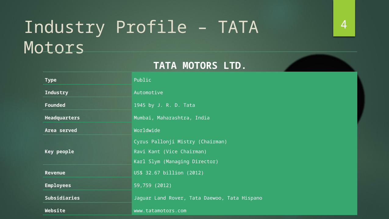
4Industry Profile – TATA MotorsTATA MOTORS LTD.
Type Public
Industry Automotive
Founded 1945 by J. R. D. Tata
Headquarters Mumbai, Maharashtra, India
Area served Worldwide
Key peopleCyrus Pallonji Mistry (Chairman)Ravi Kant (Vice Chairman)Karl Slym (Managing Director)
Revenue US$ 32.67 billion (2012)
Employees 59,759 (2012)
Subsidiaries Jaguar Land Rover, Tata Daewoo, Tata Hispano
Website www.tatamotors.com
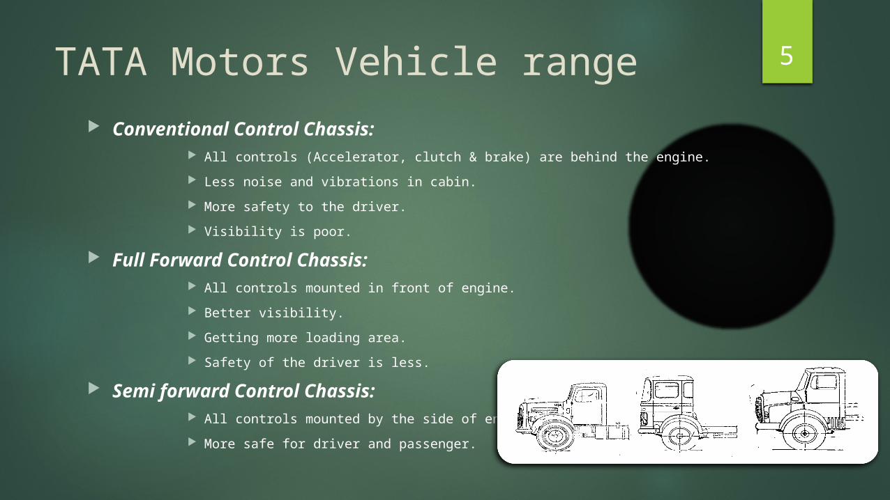
5TATA Motors Vehicle range Conventional Control Chassis:
All controls (Accelerator, clutch & brake) are behind the engine. Less noise and vibrations in cabin. More safety to the driver. Visibility is poor.
Full Forward Control Chassis: All controls mounted in front of engine. Better visibility. Getting more loading area. Safety of the driver is less.
Semi forward Control Chassis: All controls mounted by the side of engine. More safe for driver and passenger.

6Plant Locations
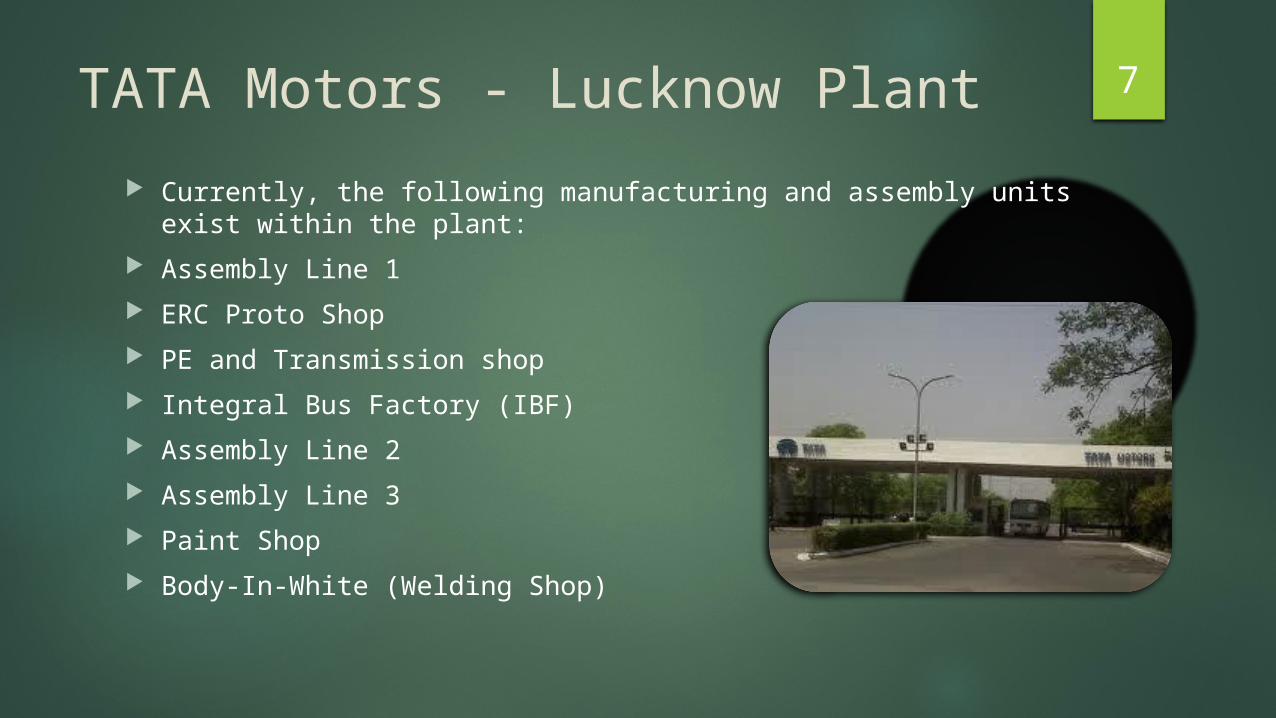
7TATA Motors - Lucknow Plant Currently, the following manufacturing and assembly units exist within the
plant: Assembly Line 1 ERC Proto Shop PE and Transmission shop Integral Bus Factory (IBF) Assembly Line 2 Assembly Line 3 Paint Shop Body-In-White (Welding Shop)
8What Is Production Engineering?Production engineering develops processes for turning raw materials into a finished item. Read on to learn more about this field and the responsibilities associated with it. Schools offering Industrial Engineering degrees can also be found in these popular choices. Production engineering is a combination of manufacturing technology with management science. A production engineer typically has a wide knowledge of engineering practices and is aware of the management challenges related to production. The goal is to accomplish the production process in the smoothest, most-judicious and most-economic way. Production engineering encompasses the application of castings, machining processing, joining processes, metal cutting & tool design, metrology, machine tools, machining systems, automation, jigs and fixtures, and die and mold design and material science and design of automobile parts and machine designing and manufacturing. Production engineering also overlaps substantially with manufacturing engineering and industrial engineering.
9Production Engineering Division (PE) - TATA
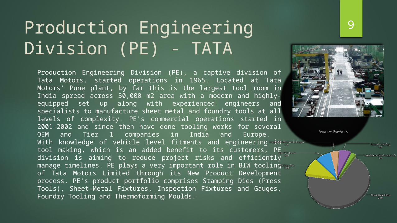
Production Engineering Division (PE), a captive division of Tata Motors, started operations in 1965. Located at Tata Motors' Pune plant, by far this is the largest tool room in India spread across 30,000 m2 area with a modern and highly-equipped set up along with experienced engineers and specialists to manufacture sheet metal and foundry tools at all levels of complexity. PE's commercial operations started in 2001-2002 and since then have done tooling works for several OEM and Tier 1 companies in India and Europe. With knowledge of vehicle level fitments and engineering in tool making, which is an added benefit to its customers, PE division is aiming to reduce project risks and efficiently manage timelines. PE plays a very important role in BIW tooling of Tata Motors Limited through its New Product Development process. PE's product portfolio comprises Stamping Dies (Press Tools), Sheet-Metal Fixtures, Inspection Fixtures and Gauges, Foundry Tooling and Thermoforming Moulds.
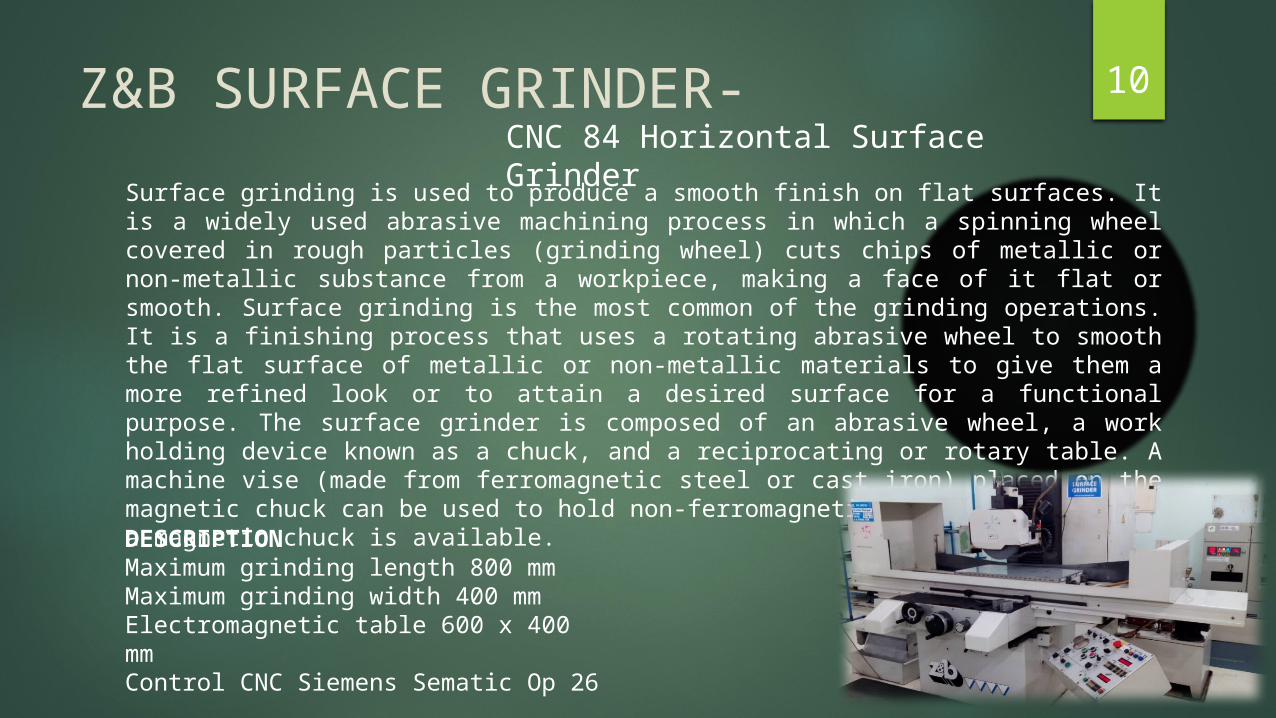
10Z&B SURFACE GRINDER-Surface grinding is used to produce a smooth finish on flat surfaces. It is a widely used abrasive machining process in which a spinning wheel covered in rough particles (grinding wheel) cuts chips of metallic or non-metallic substance from a workpiece, making a face of it flat or smooth. Surface grinding is the most common of the grinding operations. It is a finishing process that uses a rotating abrasive wheel to smooth the flat surface of metallic or non-metallic materials to give them a more refined look or to attain a desired surface for a functional purpose. The surface grinder is composed of an abrasive wheel, a work holding device known as a chuck, and a reciprocating or rotary table. A machine vise (made from ferromagnetic steel or cast iron) placed on the magnetic chuck can be used to hold non-ferromagnetic work pieces if only a magnetic chuck is available.
CNC 84 Horizontal Surface Grinder
DESCRIPTIONMaximum grinding length 800 mmMaximum grinding width 400 mmElectromagnetic table 600 x 400 mmControl CNC Siemens Sematic Op 26
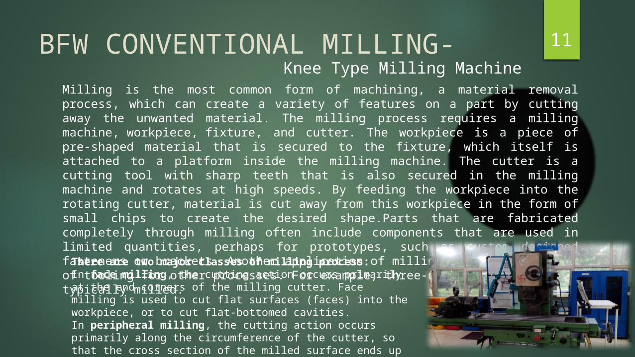
11BFW CONVENTIONAL MILLING-Milling is the most common form of machining, a material removal process, which can create a variety of features on a part by cutting away the unwanted material. The milling process requires a milling machine, workpiece, fixture, and cutter. The workpiece is a piece of pre-shaped material that is secured to the fixture, which itself is attached to a platform inside the milling machine. The cutter is a cutting tool with sharp teeth that is also secured in the milling machine and rotates at high speeds. By feeding the workpiece into the rotating cutter, material is cut away from this workpiece in the form of small chips to create the desired shape.Parts that are fabricated completely through milling often include components that are used in limited quantities, perhaps for prototypes, such as custom designed fasteners or brackets. Another application of milling is the fabrication of tooling for other processes. For example, three-dimensional molds are typically milled.
Knee Type Milling Machine
There are two major classes of milling process:In face milling, the cutting action occurs primarily at the end corners of the milling cutter. Face milling is used to cut flat surfaces (faces) into the workpiece, or to cut flat-bottomed cavities.In peripheral milling, the cutting action occurs primarily along the circumference of the cutter, so that the cross section of the milled surface ends up receiving the shape of the cutter.
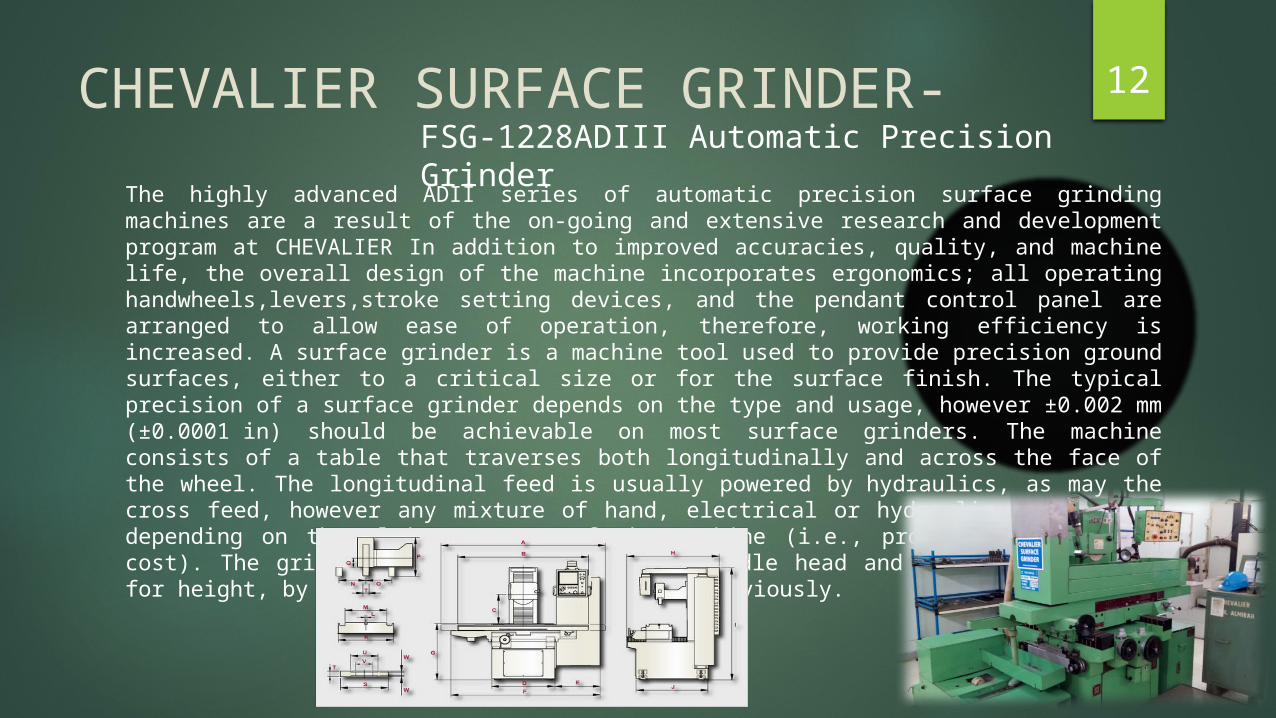
12CHEVALIER SURFACE GRINDER-The highly advanced ADII series of automatic precision surface grinding machines are a result of the on-going and extensive research and development program at CHEVALIER In addition to improved accuracies, quality, and machine life, the overall design of the machine incorporates ergonomics; all operating handwheels,levers,stroke setting devices, and the pendant control panel are arranged to allow ease of operation, therefore, working efficiency is increased. A surface grinder is a machine tool used to provide precision ground surfaces, either to a critical size or for the surface finish. The typical precision of a surface grinder depends on the type and usage, however ±0.002 mm (±0.0001 in) should be achievable on most surface grinders. The machine consists of a table that traverses both longitudinally and across the face of the wheel. The longitudinal feed is usually powered by hydraulics, as may the cross feed, however any mixture of hand, electrical or hydraulic may be used depending on the ultimate usage of the machine (i.e., production, workshop, cost). The grinding wheel rotates in the spindle head and is also adjustable for height, by any of the methods described previously.
FSG-1228ADIII Automatic Precision Grinder
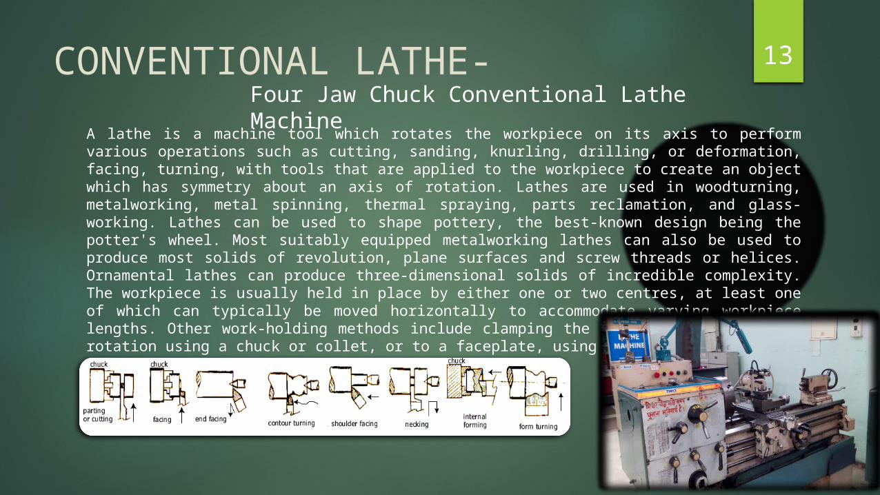
13CONVENTIONAL LATHE-A lathe is a machine tool which rotates the workpiece on its axis to perform various operations such as cutting, sanding, knurling, drilling, or deformation, facing, turning, with tools that are applied to the workpiece to create an object which has symmetry about an axis of rotation. Lathes are used in woodturning, metalworking, metal spinning, thermal spraying, parts reclamation, and glass-working. Lathes can be used to shape pottery, the best-known design being the potter's wheel. Most suitably equipped metalworking lathes can also be used to produce most solids of revolution, plane surfaces and screw threads or helices. Ornamental lathes can produce three-dimensional solids of incredible complexity. The workpiece is usually held in place by either one or two centres, at least one of which can typically be moved horizontally to accommodate varying workpiece lengths. Other work-holding methods include clamping the work about the axis of rotation using a chuck or collet, or to a faceplate, using clamps-or-dogs.
Four Jaw Chuck Conventional Lathe Machine
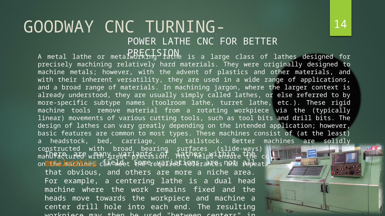
14GOODWAY CNC TURNING-A metal lathe or metalworking lathe is a large class of lathes designed for precisely machining relatively hard materials. They were originally designed to machine metals; however, with the advent of plastics and other materials, and with their inherent versatility, they are used in a wide range of applications, and a broad range of materials. In machining jargon, where the larger context is already understood, they are usually simply called lathes, or else referred to by more-specific subtype names (toolroom lathe, turret lathe, etc.). These rigid machine tools remove material from a rotating workpiece via the (typically linear) movements of various cutting tools, such as tool bits and drill bits. The design of lathes can vary greatly depending on the intended application; however, basic features are common to most types. These machines consist of (at the least) a headstock, bed, carriage, and tailstock. Better machines are solidly constructed with broad bearing surfaces (slide-ways) for stability, and manufactured with great precision. This helps ensure the components manufactured on the machines can meet the required tolerances and repeatability.
POWER LATHE CNC FOR BETTER PRECISION
There are many variants of lathes within the metalworking field. Some variations are not all that obvious, and others are more a niche area. For example, a centering lathe is a dual head machine where the work remains fixed and the heads move towards the workpiece and machine a center drill hole into each end. The resulting workpiece may then be used "between centers" in another operation.
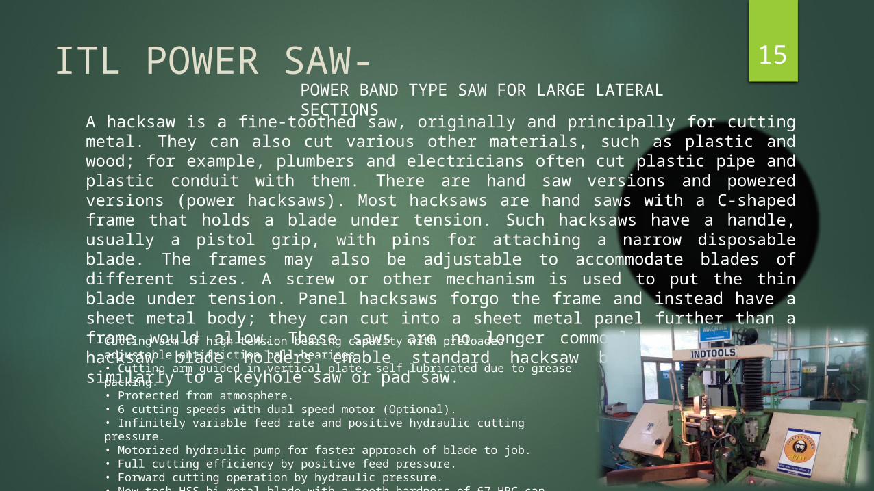
15ITL POWER SAW-A hacksaw is a fine-toothed saw, originally and principally for cutting metal. They can also cut various other materials, such as plastic and wood; for example, plumbers and electricians often cut plastic pipe and plastic conduit with them. There are hand saw versions and powered versions (power hacksaws). Most hacksaws are hand saws with a C-shaped frame that holds a blade under tension. Such hacksaws have a handle, usually a pistol grip, with pins for attaching a narrow disposable blade. The frames may also be adjustable to accommodate blades of different sizes. A screw or other mechanism is used to put the thin blade under tension. Panel hacksaws forgo the frame and instead have a sheet metal body; they can cut into a sheet metal panel further than a frame would allow. These saws are no longer commonly available, but hacksaw blade holders enable standard hacksaw blades to be used similarly to a keyhole saw or pad saw.
POWER BAND TYPE SAW FOR LARGE LATERAL SECTIONS
Cutting arm of high tension bearing capacity with preloaded adjustable antifriction ball bearings• Cutting arm guided in vertical plate, self lubricated due to grease packing. • Protected from atmosphere.• 6 cutting speeds with dual speed motor (Optional).• Infinitely variable feed rate and positive hydraulic cutting pressure. • Motorized hydraulic pump for faster approach of blade to job. • Full cutting efficiency by positive feed pressure. • Forward cutting operation by hydraulic pressure. • New tech HSS bi-metal blade with a tooth hardness of 67 HRC can also be used. • In case of hydraulic failure, blades & job are saved automatically.
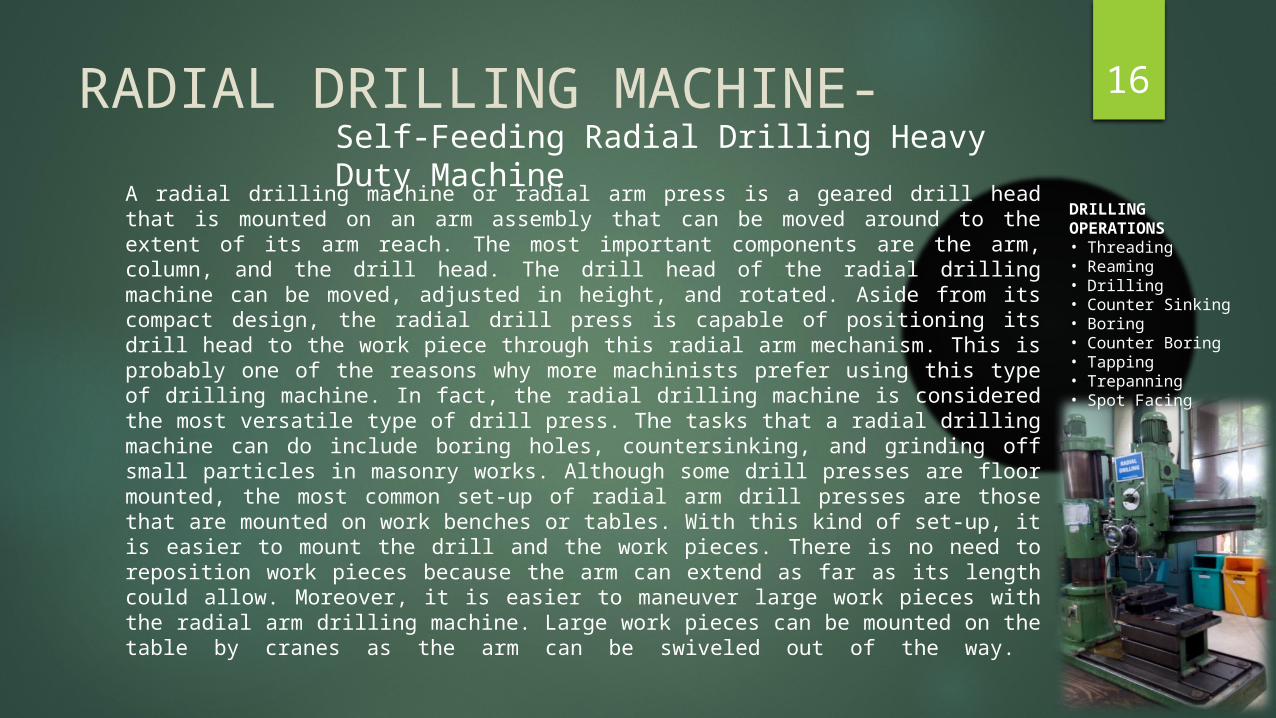
16RADIAL DRILLING MACHINE- A radial drilling machine or radial arm press is a geared drill head that is mounted on an arm assembly that can be moved around to the extent of its arm reach. The most important components are the arm, column, and the drill head. The drill head of the radial drilling machine can be moved, adjusted in height, and rotated. Aside from its compact design, the radial drill press is capable of positioning its drill head to the work piece through this radial arm mechanism. This is probably one of the reasons why more machinists prefer using this type of drilling machine. In fact, the radial drilling machine is considered the most versatile type of drill press. The tasks that a radial drilling machine can do include boring holes, countersinking, and grinding off small particles in masonry works. Although some drill presses are floor mounted, the most common set-up of radial arm drill presses are those that are mounted on work benches or tables. With this kind of set-up, it is easier to mount the drill and the work pieces. There is no need to reposition work pieces because the arm can extend as far as its length could allow. Moreover, it is easier to maneuver large work pieces with the radial arm drilling machine. Large work pieces can be mounted on the table by cranes as the arm can be swiveled out of the way.
Self-Feeding Radial Drilling Heavy Duty Machine
DRILLING OPERATIONS• Threading• Reaming• Drilling• Counter Sinking• Boring• Counter Boring• Tapping• Trepanning• Spot Facing
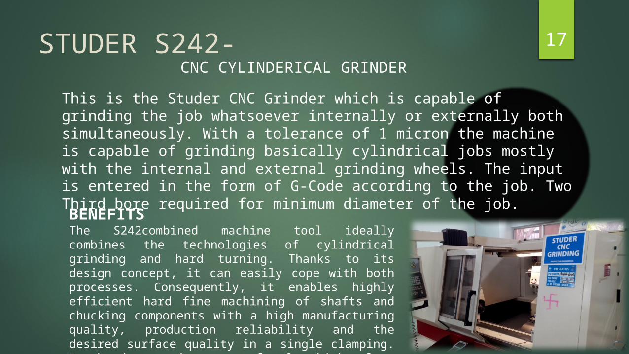
17STUDER S242-This is the Studer CNC Grinder which is capable of grinding the job whatsoever internally or externally both simultaneously. With a tolerance of 1 micron the machine is capable of grinding basically cylindrical jobs mostly with the internal and external grinding wheels. The input is entered in the form of G-Code according to the job. Two Third bore required for minimum diameter of the job.
CNC CYLINDERICAL GRINDER
BENEFITSThe S242combined machine tool ideally combines the technologies of cylindrical grinding and hard turning. Thanks to its design concept, it can easily cope with both processes. Consequently, it enables highly efficient hard fine machining of shafts and chucking components with a high manufacturing quality, production reliability and the desired surface quality in a single clamping. It is interesting not only for high-volume production but also for small batch sizes and single parts.
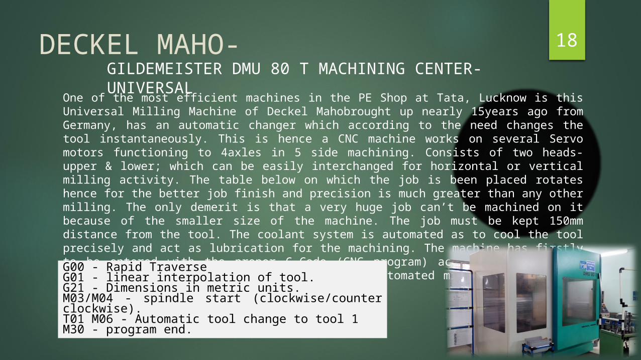
18DECKEL MAHO-One of the most efficient machines in the PE Shop at Tata, Lucknow is this Universal Milling Machine of Deckel Mahobrought up nearly 15years ago from Germany, has an automatic changer which according to the need changes the tool instantaneously. This is hence a CNC machine works on several Servo motors functioning to 4axles in 5 side machining. Consists of two heads- upper & lower; which can be easily interchanged for horizontal or vertical milling activity. The table below on which the job is been placed rotates hence for the better job finish and precision is much greater than any other milling. The only demerit is that a very huge job can’t be machined on it because of the smaller size of the machine. The job must be kept 150mm distance from the tool. The coolant system is automated as to cool the tool precisely and act as lubrication for the machining. The machine has firstly to be entered with the proper G-Code (CNC program) according to the job specification manually and then the further automated milling machine does everything.
GILDEMEISTER DMU 80 T MACHINING CENTER-UNIVERSAL
G00 - Rapid TraverseG01 - linear interpolation of tool.G21 - Dimensions in metric units.M03/M04 - spindle start (clockwise/counter clockwise).T01 M06 - Automatic tool change to tool 1M30 - program end.
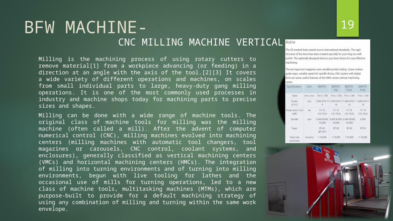
19BFW MACHINE-Milling is the machining process of using rotary cutters to remove material[1] from a workpiece advancing (or feeding) in a direction at an angle with the axis of the tool.[2][3] It covers a wide variety of different operations and machines, on scales from small individual parts to large, heavy-duty gang milling operations. It is one of the most commonly used processes in industry and machine shops today for machining parts to precise sizes and shapes.Milling can be done with a wide range of machine tools. The original class of machine tools for milling was the milling machine (often called a mill). After the advent of computer numerical control (CNC), milling machines evolved into machining centers (milling machines with automatic tool changers, tool magazines or carousels, CNC control, coolant systems, and enclosures), generally classified as vertical machining centers (VMCs) and horizontal machining centers (HMCs). The integration of milling into turning environments and of turning into milling environments, begun with live tooling for lathes and the occasional use of mills for turning operations, led to a new class of machine tools, multitasking machines (MTMs), which are purpose-built to provide for a default machining strategy of using any combination of milling and turning within the same work envelope.
CNC MILLING MACHINE VERTICAL
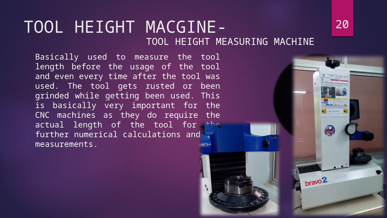
20TOOL HEIGHT MACGINE-Basically used to measure the tool length before the usage of the tool and even every time after the tool was used. The tool gets rusted or been grinded while getting been used. This is basically very important for the CNC machines as they do require the actual length of the tool for the further numerical calculations and the measurements.
TOOL HEIGHT MEASURING MACHINE
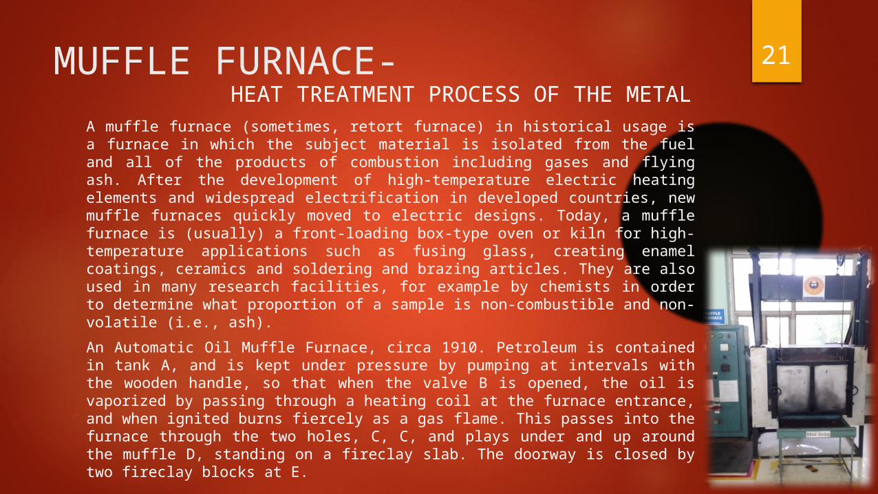
21MUFFLE FURNACE-A muffle furnace (sometimes, retort furnace) in historical usage is a furnace in which the subject material is isolated from the fuel and all of the products of combustion including gases and flying ash. After the development of high-temperature electric heating elements and widespread electrification in developed countries, new muffle furnaces quickly moved to electric designs. Today, a muffle furnace is (usually) a front-loading box-type oven or kiln for high-temperature applications such as fusing glass, creating enamel coatings, ceramics and soldering and brazing articles. They are also used in many research facilities, for example by chemists in order to determine what proportion of a sample is non-combustible and non-volatile (i.e., ash).An Automatic Oil Muffle Furnace, circa 1910. Petroleum is contained in tank A, and is kept under pressure by pumping at intervals with the wooden handle, so that when the valve B is opened, the oil is vaporized by passing through a heating coil at the furnace entrance, and when ignited burns fiercely as a gas flame. This passes into the furnace through the two holes, C, C, and plays under and up around the muffle D, standing on a fireclay slab. The doorway is closed by two fireclay blocks at E.
HEAT TREATMENT PROCESS OF THE METAL
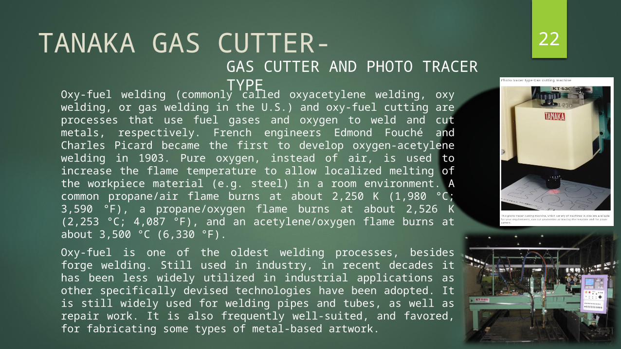
22TANAKA GAS CUTTER-Oxy-fuel welding (commonly called oxyacetylene welding, oxy welding, or gas welding in the U.S.) and oxy-fuel cutting are processes that use fuel gases and oxygen to weld and cut metals, respectively. French engineers Edmond Fouché and Charles Picard became the first to develop oxygen-acetylene welding in 1903. Pure oxygen, instead of air, is used to increase the flame temperature to allow localized melting of the workpiece material (e.g. steel) in a room environment. A common propane/air flame burns at about 2,250 K (1,980 °C; 3,590 °F), a propane/oxygen flame burns at about 2,526 K (2,253 °C; 4,087 °F), and an acetylene/oxygen flame burns at about 3,500 °C (6,330 °F).Oxy-fuel is one of the oldest welding processes, besides forge welding. Still used in industry, in recent decades it has been less widely utilized in industrial applications as other specifically devised technologies have been adopted. It is still widely used for welding pipes and tubes, as well as repair work. It is also frequently well-suited, and favored, for fabricating some types of metal-based artwork.
GAS CUTTER AND PHOTO TRACER TYPE

23Case Study I: - Oil Sumps for Engines
This Case study gives an insight on how the part design can be simplified by optimization in virtual tryout / simulation. Oil sumps of various Tata Motors projects were made feasible using virtual tryout tools. The learning from these exercises were documented to enable product designers to design oil-sumps to engine requirements in shortest possible virtual tryout loops.The exercise made possible Implementation of 3-Ply Sandwich material for special NVH (Noise, Vibrations and Harshness) application in one of the Oil Sumps.
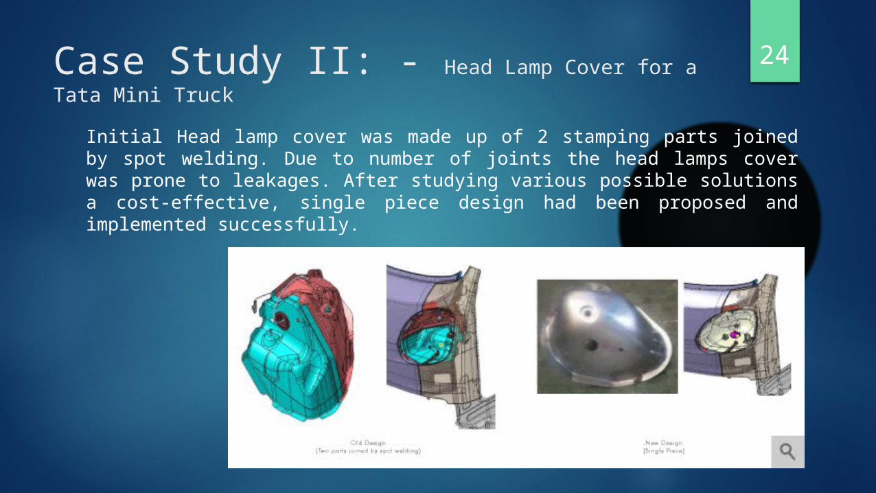
24Case Study II: - Head Lamp Cover for a Tata Mini Truck
Initial Head lamp cover was made up of 2 stamping parts joined by spot welding. Due to number of joints the head lamps cover was prone to leakages. After studying various possible solutions a cost-effective, single piece design had been proposed and implemented successfully.
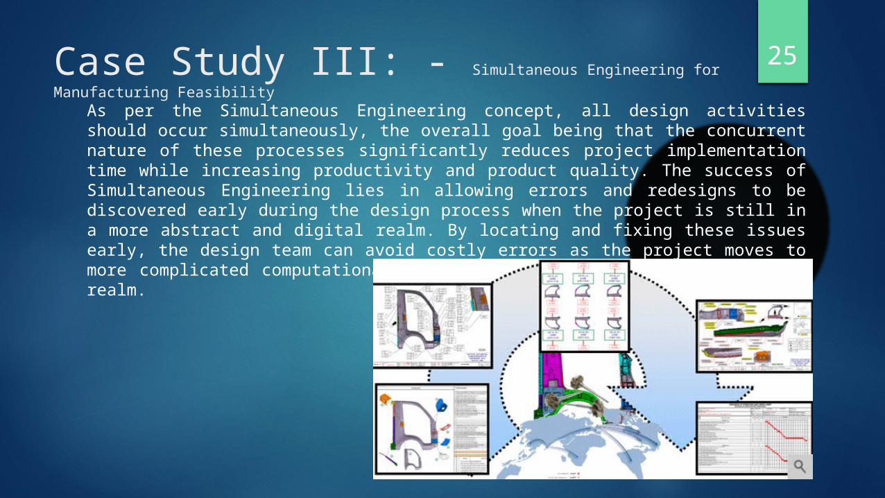
25Case Study III: - Simultaneous Engineering for Manufacturing Feasibility
As per the Simultaneous Engineering concept, all design activities should occur simultaneously, the overall goal being that the concurrent nature of these processes significantly reduces project implementation time while increasing productivity and product quality. The success of Simultaneous Engineering lies in allowing errors and redesigns to be discovered early during the design process when the project is still in a more abstract and digital realm. By locating and fixing these issues early, the design team can avoid costly errors as the project moves to more complicated computational models and eventually into the physical realm.
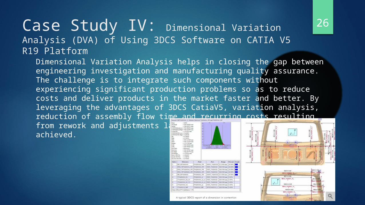
26Case Study IV: Dimensional Variation Analysis (DVA) of Using 3DCS Software on CATIA V5 R19 Platform
Dimensional Variation Analysis helps in closing the gap between engineering investigation and manufacturing quality assurance. The challenge is to integrate such components without experiencing significant production problems so as to reduce costs and deliver products in the market faster and better. By leveraging the advantages of 3DCS CatiaV5, variation analysis, reduction of assembly flow time and recurring costs resulting from rework and adjustments late in the production cycle can be achieved.
27LearningFrom this Production Engineering Department Case Study we can learn few very basic and important learning’s. That the PE department is really very important and is the only which consists of a lot of machines and equipment for the manufacturing processes. PE's commercial operations started in 2001-2002 and since then have done tooling works for several OEM and Tier 1 companies in India and Europe. With knowledge of vehicle level fitments and engineering in tool making, which is an added benefit to its customers, PE division is aiming to reduce project risks and efficiently manage timelines.PE plays a very important role in BIW tooling of Tata Motors Limited through its New Product Development process.PE's product portfolio comprises Stamping Dies (Press Tools), Sheet-Metal Fixtures, Inspection Fixtures and Gauges, Foundry Tooling and Thermoforming Moulds.

28
THANK YOU-submitted by
Swapnil SrivastavaME-B (1203340170)