Embed Size (px)
Citation preview
1
FORM-1
For
PROPOSED EXPANSION OF RESINS,
PHARMACEUTICAL INTERMEDIATES, PERFUMERY
PRODUCTS AND SPECIALTY CHEMICALS IN
EXISTING UNIT
Of
M/s. Vapi Products Industries Pvt. Ltd.
Plot No. 789/3A & 791/4 & 5,
Phase-III, G.I.D.C., Vapi-396 195,
Di: Valsad, State: Gujarat
NABL Accredited Testing Laboratory
ISO 9001:2008 Certified Company
Aqua-Air Environmental Engineers P. Ltd.
403, Centre Point, Nr. Kadiwala School, Ring
Road, Surat - 395002
Prepared By:
NABL Accredited Testing Laboratory
ISO 9001:2008 Certified Company
Aqua-Air Environmental Engineers P. Ltd.
403, Centre Point, Nr. Kadiwala School, Ring
Road, Surat - 395002
NABL Accredited Testing Laboratory
ISO 9001:2008 Certified Company
Aqua-Air Environmental Engineers P. Ltd.
403, Centre Point, Nr. Kadiwala School, Ring
Road, Surat - 395002
Prepared By:
2
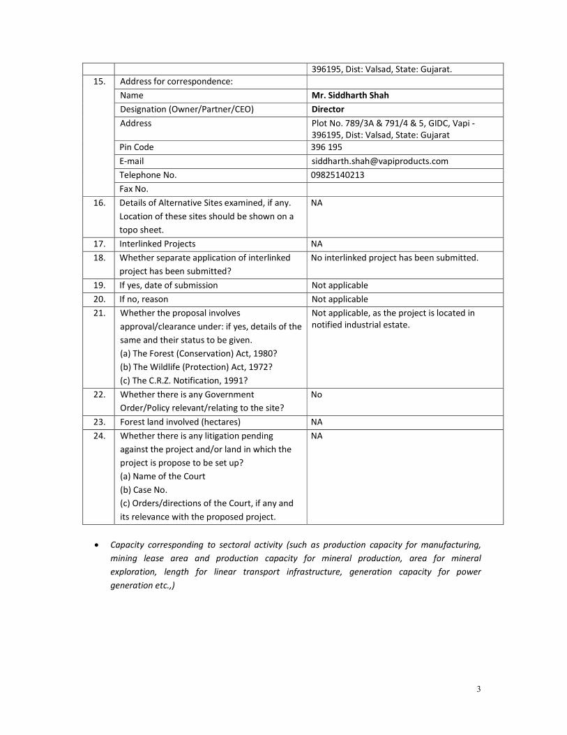
APPENDIX I (See paragraph - 6)
FORM 1
Sr.
No.
Item Details
1. Name of the project/s VAPI PRODUCTS INDUSTRIES PVT. LTD.
2. S. No. in the schedule 5(f)
3. Proposed capacity/area/length/ tonnage to be
handled/command area /lease area/number of
wells to be drilled
Existing: 150 TPM + Additional Capacity: 2750
TPM = Total after proposed expansion
capacity: 2900 TPM.
Plot Area: 9757 m2
No bore well to be drilled within the premises.
(Water source from GIDC Vapi Only).
List of Products and raw materials are given as
Annexure –2.
4. New/Expansion/Modernization Expansion
5. Existing Capacity/Area etc. Existing Capacity: 150 TPM
Plot Area: 9757 m2
6. Category of Project i.e. ‘A’ or ‘B’ 'A' (Unit is located within the 5 km of Gujarat &
Union Territory boundary i.e. Daman and
Dadranagar Haveli)
7. Does it attract the general condition? If yes,
please specify.
No
8. Does it attract the specific condition? If yes,
please specify.
No
9. Location
Plot/Survey/Khasra No. 789/3A &791/4 & 5,
Village GIDC, Vapi
Tehsil Pardi
District Valsad
State Gujarat
10. Nearest railway station/airport along with
distance in kms.
Railway Station: Vapi (4 km)
Airport: Surat (130 km)
11. Nearest Town, city, District Headquarters
along with distance in kms.
Nagar palika Vapi (4 kms), Valsad (District
Headquarter) (30 km)
12. Village Panchayats, Zilla Parishad, Municipal
Corporation, local body (complete postal
address with telephone nos. to be given)
Vapi Nagar palika, Dist: Valsad
13. Name of the applicant VAPI PRODUCTS INDUSTRIES PVT. LTD.
14. Registered Address Plot No. 789/3A & 791/4 & 5, GIDC, Vapi -
3
396195, Dist: Valsad, State: Gujarat.
15. Address for correspondence:
Name Mr. Siddharth Shah
Designation (Owner/Partner/CEO) Director
Address Plot No. 789/3A & 791/4 & 5, GIDC, Vapi -
396195, Dist: Valsad, State: Gujarat
Pin Code 396 195
E-mail [email protected]
Telephone No. 09825140213
Fax No.
16. Details of Alternative Sites examined, if any.
Location of these sites should be shown on a
topo sheet.
NA
17. Interlinked Projects NA
18. Whether separate application of interlinked
project has been submitted?
No interlinked project has been submitted.
19. If yes, date of submission Not applicable
20. If no, reason Not applicable
21. Whether the proposal involves
approval/clearance under: if yes, details of the
same and their status to be given.
(a) The Forest (Conservation) Act, 1980?
(b) The Wildlife (Protection) Act, 1972?
(c) The C.R.Z. Notification, 1991?
Not applicable, as the project is located in
notified industrial estate.
22. Whether there is any Government
Order/Policy relevant/relating to the site?
No
23. Forest land involved (hectares) NA
24. Whether there is any litigation pending
against the project and/or land in which the
project is propose to be set up?
(a) Name of the Court
(b) Case No.
(c) Orders/directions of the Court, if any and
its relevance with the proposed project.
NA
• Capacity corresponding to sectoral activity (such as production capacity for manufacturing,
mining lease area and production capacity for mineral production, area for mineral
exploration, length for linear transport infrastructure, generation capacity for power
generation etc.,)
4
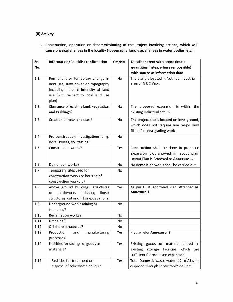
(II) Activity
1. Construction, operation or decommissioning of the Project involving actions, which will
cause physical changes in the locality (topography, land use, changes in water bodies, etc.)
Sr.
No.
Information/Checklist confirmation Yes/No Details thereof with approximate
quantities frates, wherever possible)
with source of information data
1.1 Permanent or temporary change in
land use, land cover or topography
including increase intensity of land
use (with respect to local land use
plan)
No The plant is located in Notified Industrial
area of GIDC Vapi.
1.2 Clearance of existing land, vegetation
and Buildings?
No The proposed expansion is within the
existing industrial set up.
1.3 Creation of new land uses?
No The project site is located on level ground,
which does not require any major land
filling for area grading work.
1.4 Pre-construction investigations e. g.
bore Houses, soil testing?
No
1.5 Construction works? Yes Construction shall be done in proposed
expansion plot showed in layout plan.
Layout Plan is Attached as Annexure 1.
1.6 Demolition works? No No demolition works shall be carried out.
1.7 Temporary sites used for
construction works or housing of
construction workers?
No
1.8 Above ground buildings, structures
or earthworks including linear
structures, cut and fill or excavations
Yes As per GIDC approved Plan, Attached as
Annexure 1.
1.9 Underground works mining or
tunneling?
No
1.10 Reclamation works? No
1.11 Dredging? No
1.12 Off shore structures? No
1.13 Production and manufacturing
processes?
Yes Please refer Annexure: 3
1.14 Facilities for storage of goods or
materials?
Yes Existing goods or material stored in
existing storage facilities which are
sufficient for proposed expansion.
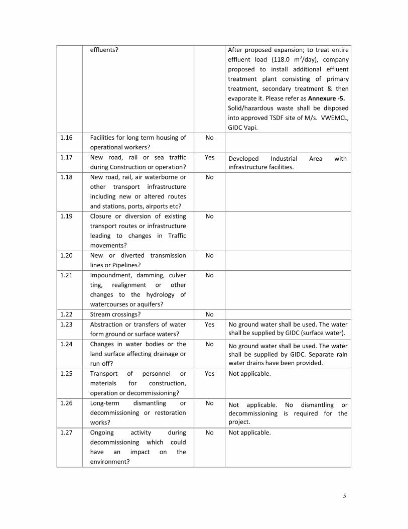
1.15 Facilities for treatment or
disposal of solid waste or liquid
Yes Total Domestic waste water (12 m3/day) is
disposed through septic tank/soak pit.
5
effluents? After proposed expansion; to treat entire
effluent load (118.0 m3/day), company
proposed to install additional effluent
treatment plant consisting of primary
treatment, secondary treatment & then
evaporate it. Please refer as Annexure -5.
Solid/hazardous waste shall be disposed
into approved TSDF site of M/s. VWEMCL,
GIDC Vapi.
1.16 Facilities for long term housing of
operational workers?
No
1.17 New road, rail or sea traffic
during Construction or operation?
Yes Developed Industrial Area with
infrastructure facilities.
1.18 New road, rail, air waterborne or
other transport infrastructure
including new or altered routes
and stations, ports, airports etc?
No
1.19 Closure or diversion of existing
transport routes or infrastructure
leading to changes in Traffic
movements?
No
1.20 New or diverted transmission
lines or Pipelines?
No
1.21 Impoundment, damming, culver
ting, realignment or other
changes to the hydrology of
watercourses or aquifers?
No
1.22 Stream crossings? No
1.23 Abstraction or transfers of water
form ground or surface waters?
Yes No ground water shall be used. The water
shall be supplied by GIDC (surface water).
1.24 Changes in water bodies or the
land surface affecting drainage or
run-off?
No No ground water shall be used. The water
shall be supplied by GIDC. Separate rain
water drains have been provided.
1.25 Transport of personnel or
materials for construction,
operation or decommissioning?
Yes Not applicable.
1.26 Long-term dismantling or
decommissioning or restoration
works?
No Not applicable. No dismantling or
decommissioning is required for the
project.
1.27 Ongoing activity during
decommissioning which could
have an impact on the
environment?
No Not applicable.
6
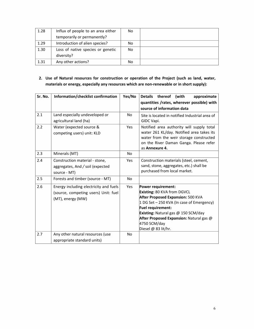
1.28 Influx of people to an area either
temporarily or permanently?
No
1.29 Introduction of alien species? No
1.30 Loss of native species or genetic
diversity?
No
1.31 Any other actions? No
2. Use of Natural resources for construction or operation of the Project (such as land, water,
materials or energy, especially any resources which are non-renewable or in short supply):
Sr. No. Information/checklist confirmation Yes/No Details thereof (with approximate
quantities /rates, wherever possible) with
source of information data
2.1 Land especially undeveloped or
agricultural land (ha)
No Site is located in notified Industrial area of
GIDC Vapi.
2.2 Water (expected source &
competing users) unit: KLD
Yes Notified area authority will supply total
water 261 KL/day. Notified area takes its
water from the weir storage constructed
on the River Daman Ganga. Please refer
as Annexure 4.
2.3 Minerals (MT) No
2.4 Construction material - stone,
aggregates, And / soil (expected
source - MT)
Yes Construction materials (steel, cement,
sand, stone, aggregates, etc.) shall be
purchased from local market.
2.5 Forests and timber (source - MT) No
2.6 Energy including electricity and fuels
(source, competing users) Unit: fuel
(MT), energy (MW)
Yes Power requirement:
Existing: 80 KVA from DGVCL
After Proposed Expansion: 500 KVA
1 DG Set – 250 KVA (In case of Emergency)
Fuel requirement:
Existing: Natural gas @ 150 SCM/day
After Proposed Expansion: Natural gas @
4750 SCM/day
Diesel @ 83 lit/hr.
2.7 Any other natural resources (use
appropriate standard units)
No
7
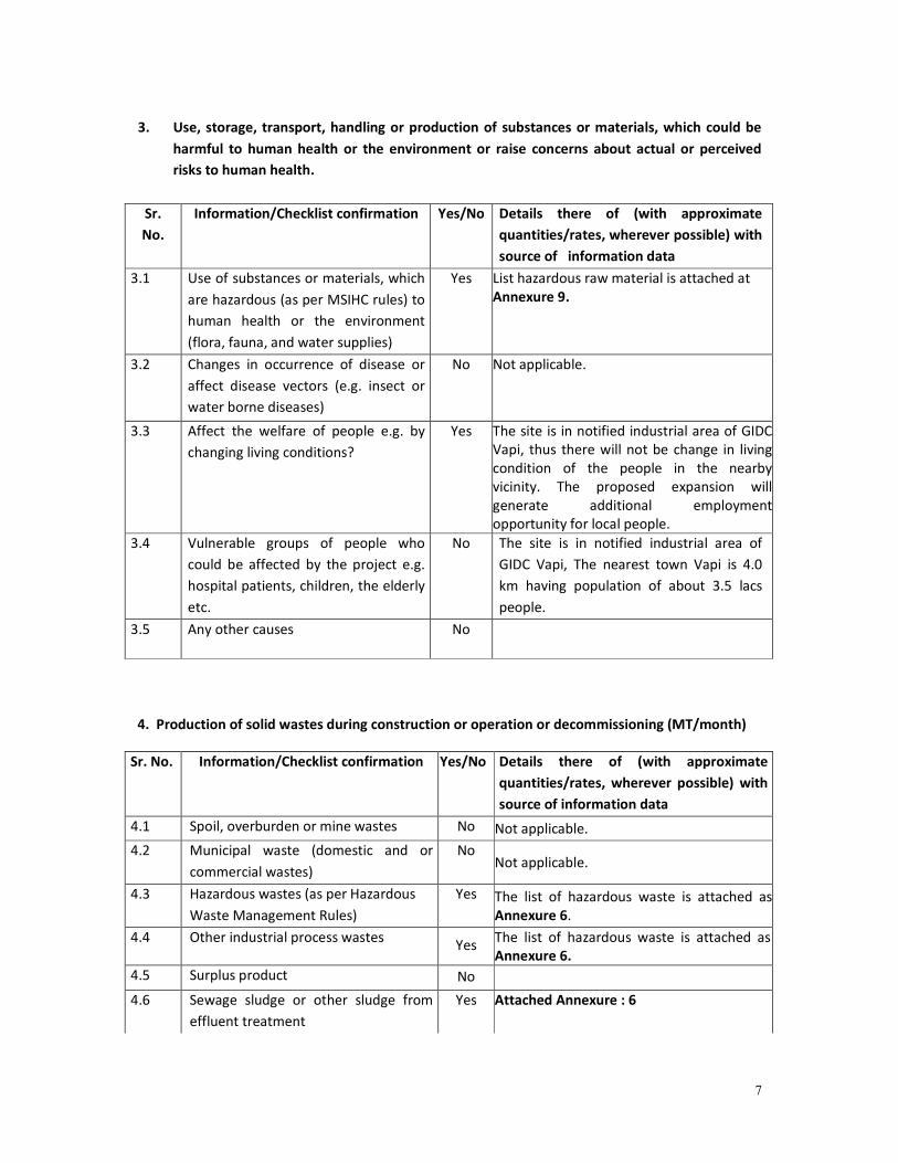
3. Use, storage, transport, handling or production of substances or materials, which could be
harmful to human health or the environment or raise concerns about actual or perceived
risks to human health.
Sr.
No.
Information/Checklist confirmation Yes/No Details there of (with approximate
quantities/rates, wherever possible) with
source of information data
3.1 Use of substances or materials, which
are hazardous (as per MSIHC rules) to
human health or the environment
(flora, fauna, and water supplies)
Yes List hazardous raw material is attached at
Annexure 9.
3.2 Changes in occurrence of disease or
affect disease vectors (e.g. insect or
water borne diseases)
No Not applicable.
3.3 Affect the welfare of people e.g. by
changing living conditions?
Yes The site is in notified industrial area of GIDC
Vapi, thus there will not be change in living
condition of the people in the nearby
vicinity. The proposed expansion will
generate additional employment
opportunity for local people.
3.4 Vulnerable groups of people who
could be affected by the project e.g.
hospital patients, children, the elderly
etc.
No The site is in notified industrial area of
GIDC Vapi, The nearest town Vapi is 4.0
km having population of about 3.5 lacs
people.
3.5 Any other causes No
4. Production of solid wastes during construction or operation or decommissioning (MT/month)
Sr. No. Information/Checklist confirmation Yes/No Details there of (with approximate
quantities/rates, wherever possible) with
source of information data
4.1 Spoil, overburden or mine wastes No Not applicable.
4.2 Municipal waste (domestic and or
commercial wastes)
No Not applicable.
4.3 Hazardous wastes (as per Hazardous
Waste Management Rules)
Yes The list of hazardous waste is attached as
Annexure 6.
4.4 Other industrial process wastes Yes
The list of hazardous waste is attached as
Annexure 6.
4.5 Surplus product No
4.6 Sewage sludge or other sludge from
effluent treatment
Yes
Attached Annexure : 6
8
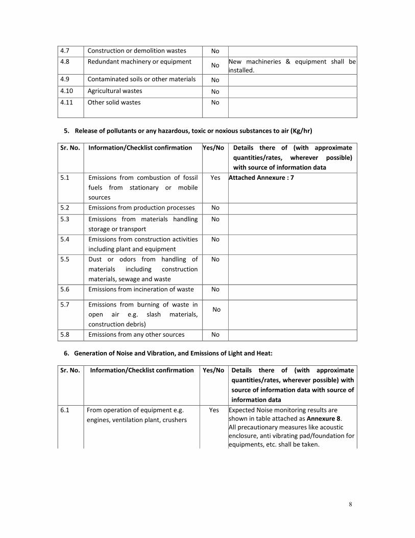
4.7 Construction or demolition wastes No
4.8 Redundant machinery or equipment No
New machineries & equipment shall be
installed.
4.9 Contaminated soils or other materials No
4.10 Agricultural wastes No
4.11 Other solid wastes No
5. Release of pollutants or any hazardous, toxic or noxious substances to air (Kg/hr)
Sr. No. Information/Checklist confirmation Yes/No Details there of (with approximate
quantities/rates, wherever possible)
with source of information data
5.1 Emissions from combustion of fossil
fuels from stationary or mobile
sources
Yes Attached Annexure : 7
5.2 Emissions from production processes No
5.3 Emissions from materials handling
storage or transport
No
5.4 Emissions from construction activities
including plant and equipment
No
5.5 Dust or odors from handling of
materials including construction
materials, sewage and waste
No
5.6 Emissions from incineration of waste No
5.7 Emissions from burning of waste in
open air e.g. slash materials,
construction debris)
No
5.8 Emissions from any other sources No
6. Generation of Noise and Vibration, and Emissions of Light and Heat:
Sr. No. Information/Checklist confirmation Yes/No Details there of (with approximate
quantities/rates, wherever possible) with
source of information data with source of
information data
6.1 From operation of equipment e.g.
engines, ventilation plant, crushers
Yes Expected Noise monitoring results are
shown in table attached as Annexure 8.
All precautionary measures like acoustic
enclosure, anti vibrating pad/foundation for
equipments, etc. shall be taken.
9
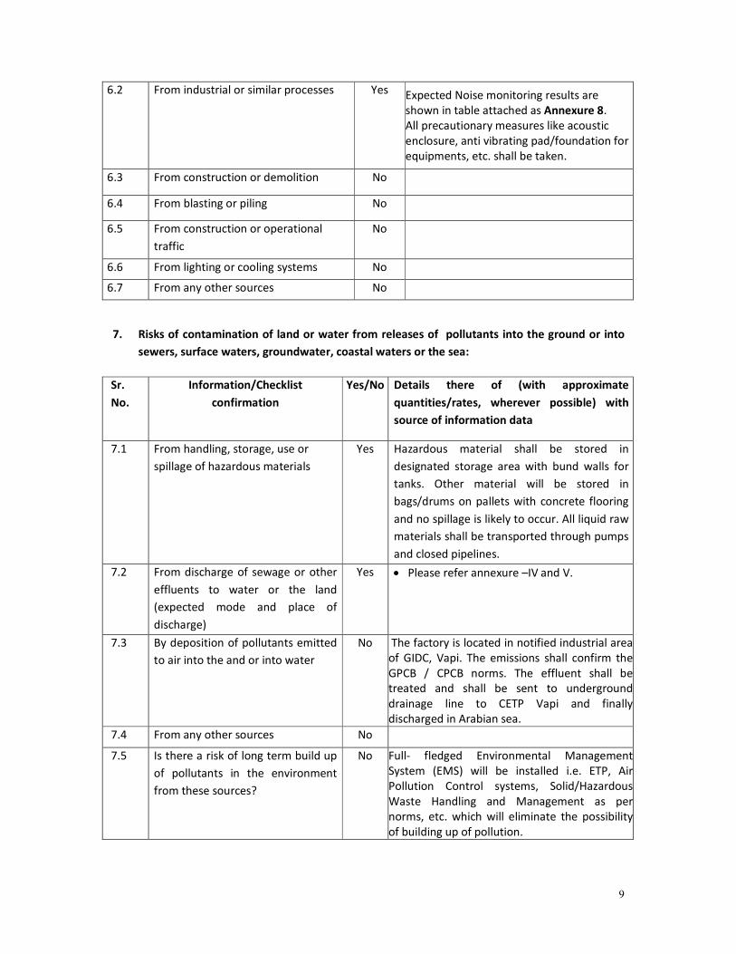
6.2 From industrial or similar processes Yes Expected Noise monitoring results are
shown in table attached as Annexure 8.
All precautionary measures like acoustic
enclosure, anti vibrating pad/foundation for
equipments, etc. shall be taken.
6.3 From construction or demolition No
6.4 From blasting or piling No
6.5 From construction or operational
traffic
No
6.6 From lighting or cooling systems No
6.7 From any other sources No
7. Risks of contamination of land or water from releases of pollutants into the ground or into
sewers, surface waters, groundwater, coastal waters or the sea:
Sr.
No.
Information/Checklist
confirmation
Yes/No Details there of (with approximate
quantities/rates, wherever possible) with
source of information data
7.1 From handling, storage, use or
spillage of hazardous materials
Yes Hazardous material shall be stored in
designated storage area with bund walls for
tanks. Other material will be stored in
bags/drums on pallets with concrete flooring
and no spillage is likely to occur. All liquid raw
materials shall be transported through pumps
and closed pipelines.
7.2 From discharge of sewage or other
effluents to water or the land
(expected mode and place of
discharge)
Yes • Please refer annexure –IV and V.
7.3 By deposition of pollutants emitted
to air into the and or into water
No The factory is located in notified industrial area
of GIDC, Vapi. The emissions shall confirm the
GPCB / CPCB norms. The effluent shall be
treated and shall be sent to underground
drainage line to CETP Vapi and finally
discharged in Arabian sea.
7.4 From any other sources No
7.5 Is there a risk of long term build up
of pollutants in the environment
from these sources?
No Full- fledged Environmental Management
System (EMS) will be installed i.e. ETP, Air
Pollution Control systems, Solid/Hazardous
Waste Handling and Management as per
norms, etc. which will eliminate the possibility
of building up of pollution.
10
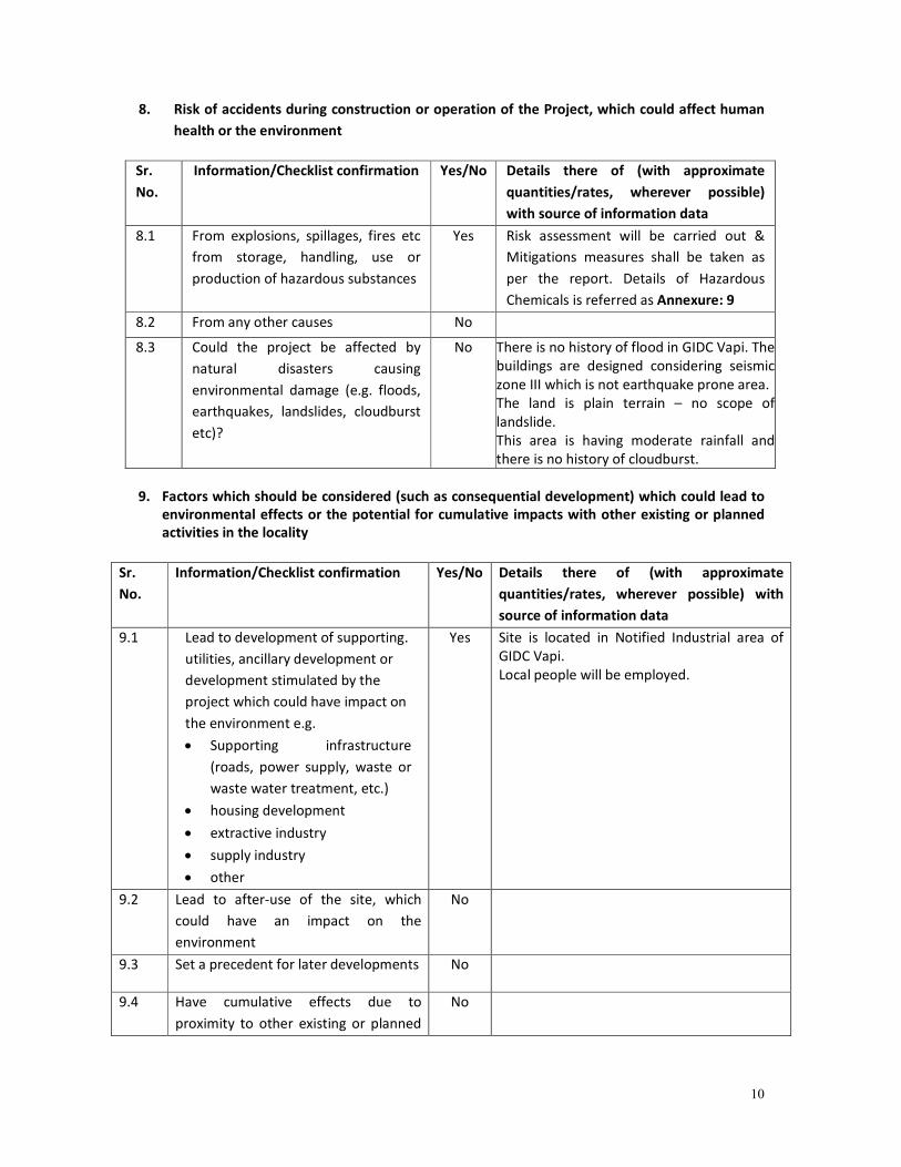
8. Risk of accidents during construction or operation of the Project, which could affect human
health or the environment
Sr.
No.
Information/Checklist confirmation Yes/No Details there of (with approximate
quantities/rates, wherever possible)
with source of information data
8.1 From explosions, spillages, fires etc
from storage, handling, use or
production of hazardous substances
Yes Risk assessment will be carried out &
Mitigations measures shall be taken as
per the report. Details of Hazardous
Chemicals is referred as Annexure: 9
8.2 From any other causes No
8.3 Could the project be affected by
natural disasters causing
environmental damage (e.g. floods,
earthquakes, landslides, cloudburst
etc)?
No There is no history of flood in GIDC Vapi. The
buildings are designed considering seismic
zone III which is not earthquake prone area.
The land is plain terrain – no scope of
landslide.
This area is having moderate rainfall and
there is no history of cloudburst.
9. Factors which should be considered (such as consequential development) which could lead to
environmental effects or the potential for cumulative impacts with other existing or planned
activities in the locality
Sr.
No.
Information/Checklist confirmation
Yes/No
Details there of (with approximate
quantities/rates, wherever possible) with
source of information data
9.1 Lead to development of supporting.
utilities, ancillary development or
development stimulated by the
project which could have impact on
the environment e.g.
• Supporting infrastructure
(roads, power supply, waste or
waste water treatment, etc.)
• housing development
• extractive industry
• supply industry
• other
Yes Site is located in Notified Industrial area of
GIDC Vapi.
Local people will be employed.
9.2 Lead to after-use of the site, which
could have an impact on the
environment
No
9.3 Set a precedent for later developments No
9.4 Have cumulative effects due to
proximity to other existing or planned
No
11
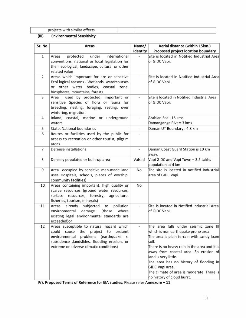
(III) Environmental Sensitivity
Sr. No. Areas Name/
Identity
Aerial distance (within 15km.)
Proposed project location boundary
1 Areas protected under international
conventions, national or local legislation for
their ecological, landscape, cultural or other
related value
- Site is located in Notified Industrial Area
of GIDC Vapi.
2 Areas which important for are or sensitive
Ecol logical reasons - Wetlands, watercourses
or other water bodies, coastal zone,
biospheres, mountains, forests
- Site is located in Notified Industrial Area
of GIDC Vapi.
3 Area used by protected, important or
sensitive Species of flora or fauna for
breeding, nesting, foraging, resting, over
wintering, migration
- Site is located in Notified Industrial Area
of GIDC Vapi.
4 Inland, coastal, marine or underground
waters
- Arabian Sea : 15 kms
Damanganga River: 3 kms
5 State, National boundaries - Daman UT Boundary : 4.8 km
6 Routes or facilities used by the public for
access to recreation or other tourist, pilgrim
areas
-
7 Defense installations - Daman Coast Guard Station is 10 km
away.
8 Densely populated or built-up area Valsad Vapi GIDC and Vapi Town – 3.5 Lakhs
population at 4 km
9 Area occupied by sensitive man-made land
uses Hospitals, schools, places of worship,
community facilities)
No The site is located in notified industrial
area of GIDC Vapi.
10 Areas containing important, high quality or
scarce resources (ground water resources,
surface resources, forestry, agriculture,
fisheries, tourism, minerals)
No
11 Areas already subjected to pollution
environmental damage. (those where
existing legal environmental standards are
exceeded)or
- Site is located in Notified Industrial Area
of GIDC Vapi.
12 Areas susceptible to natural hazard which
could cause the project to present
environmental problems (earthquake s,
subsidence ,landslides, flooding erosion, or
extreme or adverse climatic conditions)
- The area falls under seismic zone III
which is non earthquake prone area.
The area is plain terrain with sandy loam
soil.
There is no heavy rain in the area and it is
away from coastal area. So erosion of
land is very little.
The area has no history of flooding in
GIDC Vapi area.
The climate of area is moderate. There is
no history of cloud burst.
IV). Proposed Terms of Reference for EIA studies: Please refer Annexure – 11
projects with similar effects
12
I hereby given undertaking that the data and information given in the application and
enclosures are true to the best of my knowledge and belief and I am aware that if any part of
the data and information submitted is found to be false or misleading at any stage, the
project will be rejected and clearance given, if any to the project will be revoked at our risk
and cost.
Date: 03/05/2016
Place: Vapi
For VAPI PRODUCTS INDUSTRIES PVT. LTD.
Mr. Siddharth Shah
(Director)
NOTE:
1. The projects involving clearance under Coastal Regulation Zone Notification, 1991 shall
submit with the application a C.R.Z. map duly demarcated by one of the authorized agencies,
showing the project activities, w.r.t. C.R.Z. (at the stage of TOR) and the recommendations of
the State Coastal Zone Management Authority (at the stage of EC). Simultaneous action shall
also be taken to obtain the requisite clearance under the provisions of the C.R.Z.
Notification, 1991 for the activities to be located in the CRZ.
2. The projects to be located within 10 km of the National Parks, Sanctuaries, Biosphere
Reserves, Migratory Corridors of Wild Animals, the project proponent shall submit the map
duly authenticated by Chief Wildlife Warden showing these features vis-à-vis the project
location and the recommendations or comments of the Chief Wildlife Warden thereon (at
the stage of EC).
3. All correspondence with the Ministry of Environment & Forests including submission of
application for TOR/Environmental Clearance, subsequent clarifications, as may be required
from time to time, participation in the EAC Meeting on behalf of the project proponent shall
be made by the authorized signatory only. The authorized signatory should also submit a
document in support of his claim of being an authorized signatory for the specific project.
13
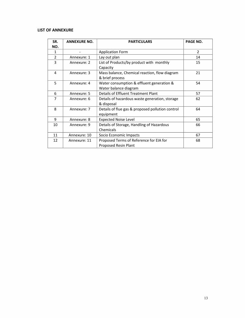
LIST OF ANNEXURE
SR.
NO.
ANNEXURE NO. PARTICULARS PAGE NO.
1 - Application Form 2
2 Annexure: 1 Lay out plan 14
3 Annexure: 2 List of Products/by product with monthly
Capacity
15
4 Annexure: 3 Mass balance, Chemical reaction, flow diagram
& brief process
21
5 Annexure: 4 Water consumption & effluent generation &
Water balance diagram
54
6 Annexure: 5 Details of Effluent Treatment Plant 57
7 Annexure: 6 Details of hazardous waste generation, storage
& disposal
62
8 Annexure: 7 Details of flue gas & proposed pollution control
equipment
64
9 Annexure: 8 Expected Noise Level 65
10 Annexure: 9 Details of Storage, Handling of Hazardous
Chemicals
66
11 Annexure: 10 Socio Economic Impacts 67
12 Annexure: 11 Proposed Terms of Reference for EIA for
Proposed Resin Plant
68
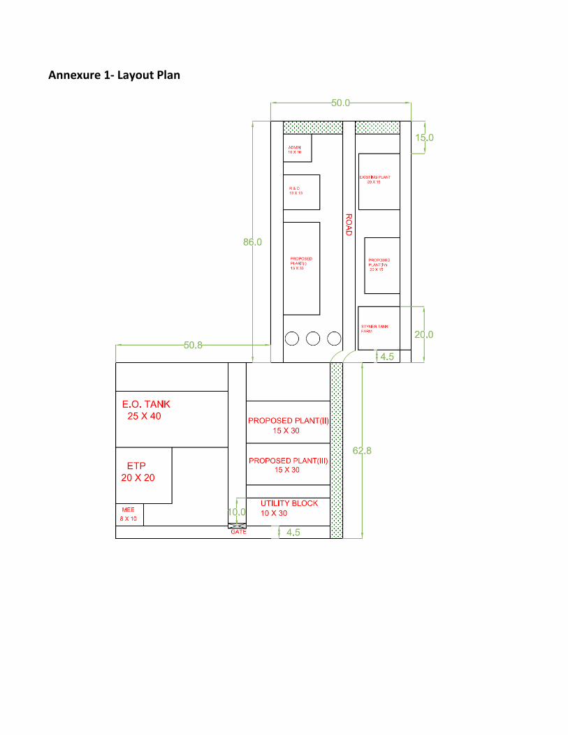
Annexure 1- Layout Plan
15
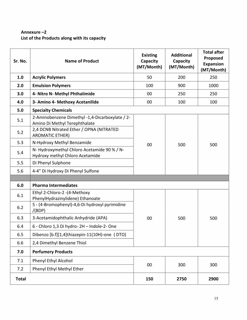
Annexure –2
List of the Products along with its capacity
Sr. No. Name of Product
Existing
Capacity
(MT/Month)
Additional
Capacity
(MT/Month)
Total after
Proposed
Expansion
(MT/Month)
1.0 Acrylic Polymers 50 200 250
2.0 Emulsion Polymers 100 900 1000
3.0 4- Nitro N- Methyl PhthaIimide 00 250 250
4.0 3- Amino 4- Methoxy Acetanilide 00 100 100
5.0 Specialty Chemicals
5.1 2-Aminobenzene Dimethyl -1,4-Dicarboxylate / 2-
Amino Di Methyl Terephthalate
00
500
500
5.2 2,4 DCNB Nitrated Ether / OPNA (NITRATED
AROMATIC ETHER)
5.3 N-Hydroxy Methyl Benzamide
5.4 N- Hydroxymethyl Chloro Acetamide 90 % / N-
Hydroxy methyl Chloro Acetamide
5.5 Di Phenyl Sulphone
5.6 4-4” Di Hydroxy Di Phenyl Sulfone
6.0 Pharma Intermediates
6.1 Ethyl 2-Chloro-2 -(4-Methoxy
PhenylHydrazinylidene) Ethanoate
00 500 500
6.2 5 - (4-Bromophenyl)-4,6-Di hydroxyl pyrimidine
/(BDP)
6.3 3-Acetamidophthalic Anhydride (APA)
6.4 6 - Chloro 1,3 Di hydro- 2H – Indole-2- One
6.5 Dibenzo [b.f][1,4]thiazepin-11(10H)-one ( DTO)
6.6 2,4 Dimethyl Benzene Thiol
7.0 Perfumery Products
7.1 Phenyl Ethyl Alcohol 00 300 300
7.2 Phenyl Ethyl Methyl Ether
Total 150 2750 2900
16
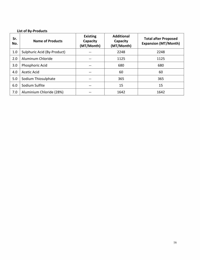
List of By-Products
Sr.
No. Name of Products
Existing
Capacity
(MT/Month)
Additional
Capacity
(MT/Month)
Total after Proposed
Expansion (MT/Month)
1.0 Sulphuric Acid (By-Product) -- 2248 2248
2.0 Aluminum Chloride -- 1125 1125
3.0 Phosphoric Acid -- 680 680
4.0 Acetic Acid -- 60 60
5.0 Sodium Thiosulphate -- 365 365
6.0 Sodium Sulfite -- 15 15
7.0 Aluminium Chloride (28%) -- 1642 1642
17
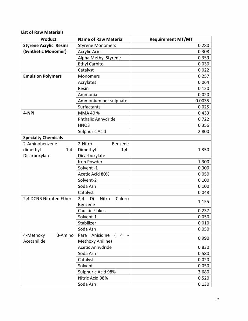
List of Raw Materials
Product Name of Raw Material Requirement MT/MT
Styrene Acrylic Resins
(Synthetic Monomer)
Styrene Monomers 0.280
Acrylic Acid 0.308
Alpha Methyl Styrene 0.359
Ethyl Carbitol 0.030
Catalyst 0.022
Emulsion Polymers Monomers 0.257
Acrylates 0.064
Resin 0.120
Ammonia 0.020
Ammonium per sulphate 0.0035
Surfactants 0.025
4-NPI MMA 40 % 0.433
Phthalic Anhydride 0.722
HNO3 0.356
Sulphuric Acid 2.800
Specialty Chemicals
2-Aminobenzene
dimethyl -1,4-
Dicarboxylate
2-Nitro Benzene
Dimethyl -1,4-
Dicarboxylate
1.350
Iron Powder 1.300
Solvent -1 0.300
Acetic Acid 80% 0.050
Solvent-2 0.100
Soda Ash 0.100
Catalyst 0.048
2,4 DCNB Nitrated Ether 2,4 Di Nitro Chloro
Benzene 1.155
Caustic Flakes 0.237
Solvent-1 0.050
Stabilizer 0.010
Soda Ash 0.050
4-Methoxy 3-Amino
Acetanilide
Para Anisidine ( 4 -
Methoxy Aniline) 0.990
Acetic Anhydride 0.830
Soda Ash 0.580
Catalyst 0.020
Solvent 0.050
Sulphuric Acid 98% 3.680
Nitric Acid 98% 0.520
Soda Ash 0.130

18
NaSH 30-33% 2.130
Caustic lye 0.060
SBS 1.010
N- Hydroxymethyl
Benzamide
Benzoyl Chloride 1.160
Ammonia 23 1.200
Catalyst-1 0.010
Salt 0.250
Solvent 0.100
Soda Ash 0.120
Para formaldehyde 0.300
Caustic lye 48 0.050
Di Phenyl Sulphone Benzene 0.050
Chloro Sulfonic Acid 0.560
Sulphuric Acid 0.030
5 % Soda Ash Solution 0.050
4,4 ' Di Hydroxy Di
Phenyl Sulfone
Phenol 0.830
Solvent – MCB 0.050
Sulphuric Acid 0.435
Sodium Bisuphite 0.025
Soda Ash 0.025
Activated Carbon 0.020
Solvent – Methanol 0.060
Pharma Intermeidates
Ethyl 2-Chloro-2 - (4-
Methoxy
Phenylhydrazinylidene)
Ethanoate
Para -Anisidine 0.560
30 % HCl Solution 0.450
Sodium Nitrite 0.290
Urea 0.150
Sodium Acetate 0.035
Ethyl 2-Chloro Aceto
Acetate 0.630
Chloroform 0.120
Isopropyl Alcohol (IPA) 0.200
5 - (4-bromophenyl)-4,6-
di hydroxyl Pyrimidine.
(BDP)
4-Bromophenyl Acetic
Acid 1.050
Sulfuric Acid 0.450
Methanol 0.300
Dichloromethane (MDC) 0.200
Sodium Hydrogen
Carbonate 0.500
Tetrahydrofuran(THF) 0.100
Sodium Methoxide 0.290
Hydrochloric Acid 0.800
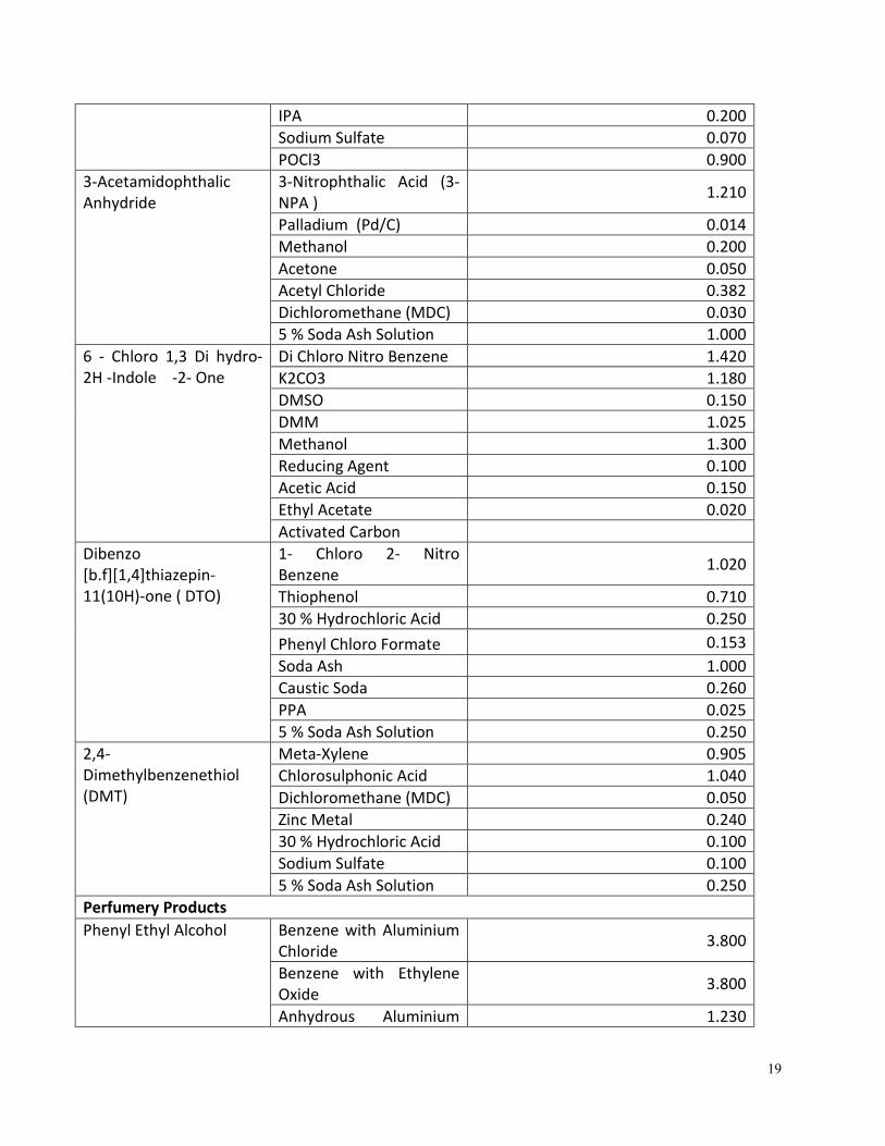
19
IPA 0.200
Sodium Sulfate 0.070
POCl3 0.900
3-Acetamidophthalic
Anhydride
3-Nitrophthalic Acid (3-
NPA ) 1.210
Palladium (Pd/C) 0.014
Methanol 0.200
Acetone 0.050
Acetyl Chloride 0.382
Dichloromethane (MDC) 0.030
5 % Soda Ash Solution 1.000
6 - Chloro 1,3 Di hydro-
2H -Indole -2- One
Di Chloro Nitro Benzene 1.420
K2CO3 1.180
DMSO 0.150
DMM 1.025
Methanol 1.300
Reducing Agent 0.100
Acetic Acid 0.150
Ethyl Acetate 0.020
Activated Carbon
Dibenzo
[b.f][1,4]thiazepin-
11(10H)-one ( DTO)
1- Chloro 2- Nitro
Benzene 1.020
Thiophenol 0.710
30 % Hydrochloric Acid 0.250
Phenyl Chloro Formate 0.153
Soda Ash 1.000
Caustic Soda 0.260
PPA 0.025
5 % Soda Ash Solution 0.250
2,4-
Dimethylbenzenethiol
(DMT)
Meta-Xylene 0.905
Chlorosulphonic Acid 1.040
Dichloromethane (MDC) 0.050
Zinc Metal 0.240
30 % Hydrochloric Acid 0.100
Sodium Sulfate 0.100
5 % Soda Ash Solution 0.250
Perfumery Products
Phenyl Ethyl Alcohol Benzene with Aluminium
Chloride 3.800
Benzene with Ethylene
Oxide 3.800
Anhydrous Aluminium 1.230
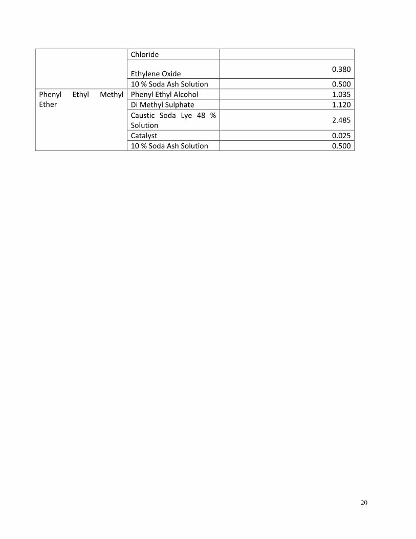
20
Chloride
Ethylene Oxide 0.380
10 % Soda Ash Solution 0.500
Phenyl Ethyl Methyl
Ether
Phenyl Ethyl Alcohol 1.035
Di Methyl Sulphate 1.120
Caustic Soda Lye 48 %
Solution 2.485
Catalyst 0.025
10 % Soda Ash Solution 0.500
21
n
HC CH2
+
C
CH3
CH2
+ O C
HO
CH2
HC
Styrene Monomer Alpha Methyl Styrene Acrylic Acid
Styrene Acrylic Resin
Styrene Acrylic Resin
2
HC CH2 CH
CH3
CH2 C
HOOC
CH2 CH CH2 CH
CH3
CH2 C
HOOC
CH2 HC
COOH
CH2
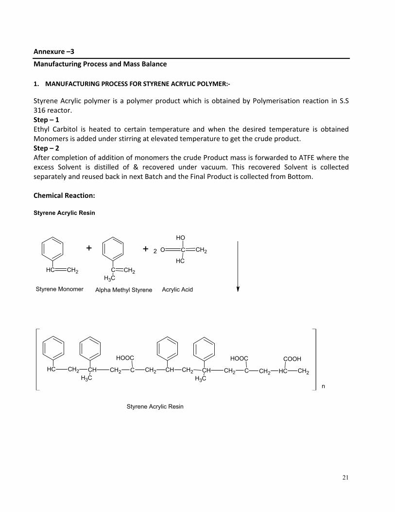
Annexure –3
Manufacturing Process and Mass Balance
1. MANUFACTURING PROCESS FOR STYRENE ACRYLIC POLYMER:-
Styrene Acrylic polymer is a polymer product which is obtained by Polymerisation reaction in S.S
316 reactor.
Step – 1
Ethyl Carbitol is heated to certain temperature and when the desired temperature is obtained
Monomers is added under stirring at elevated temperature to get the crude product.
Step – 2
After completion of addition of monomers the crude Product mass is forwarded to ATFE where the
excess Solvent is distilled of & recovered under vacuum. This recovered Solvent is collected
separately and reused back in next Batch and the Final Product is collected from Bottom.
Chemical Reaction:
22
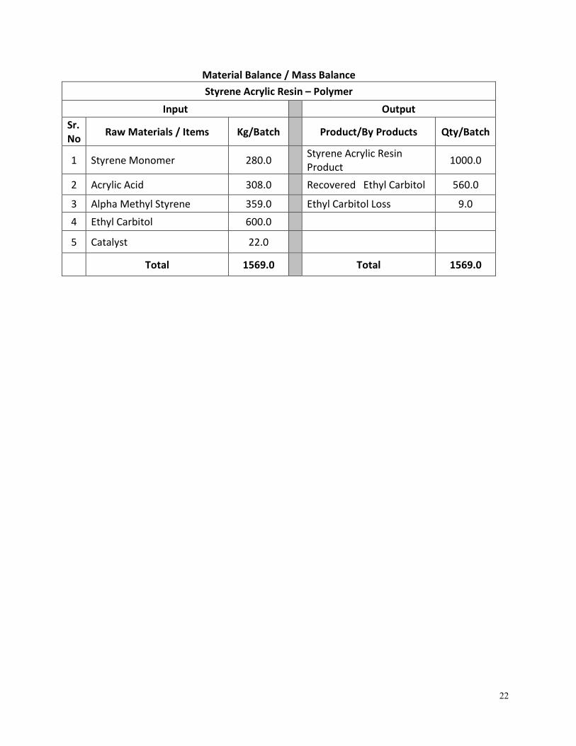
Material Balance / Mass Balance
Styrene Acrylic Resin – Polymer
Input Output
Sr.
No Raw Materials / Items Kg/Batch Product/By Products Qty/Batch
1 Styrene Monomer 280.0 Styrene Acrylic Resin
Product 1000.0
2 Acrylic Acid 308.0 Recovered Ethyl Carbitol 560.0
3 Alpha Methyl Styrene 359.0 Ethyl Carbitol Loss 9.0
4 Ethyl Carbitol 600.0
5 Catalyst 22.0
Total 1569.0 Total 1569.0
23
Resin
Emulsions Polymer
HC CH2 CH
CH3
CH2 C
HOOC
CH2 CH CH2 CH
CH3
CH2 C
HOOC
CH2 HC
COOH
CH2
+ H2C CH
C O
O CH2 HC
CH2 CH3
(CH2)3 CH3
2 Ethyl Hexyl Acrylate
+
HC CH2
Styrene Monomer NH3
H2O
HC CH2 CH
CH3
CH2 C
COOH
CH2 CH CH2 CH
CH3
CH2 C
COOH
CH2 HC
COOH
CH2 CH2 CH
C O
O CH2 HC
CH2 CH3
(CH2)3 CH3
CH CH2
n
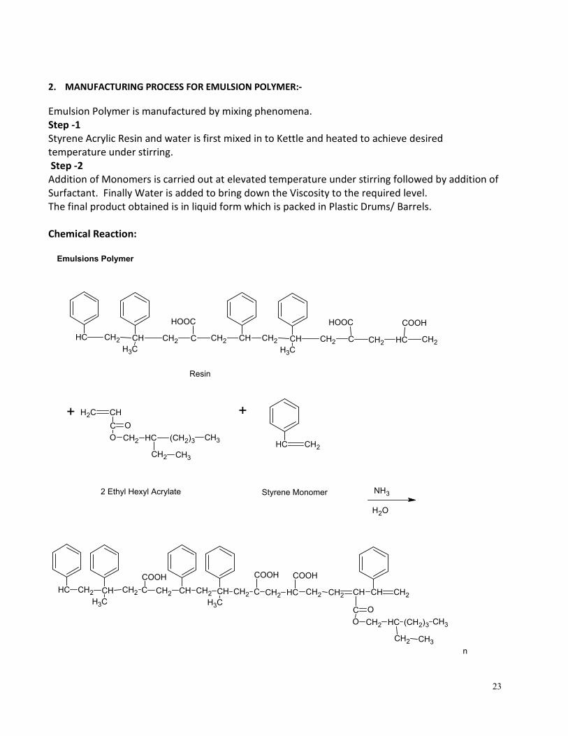
2. MANUFACTURING PROCESS FOR EMULSION POLYMER:-
Emulsion Polymer is manufactured by mixing phenomena.
Step -1
Styrene Acrylic Resin and water is first mixed in to Kettle and heated to achieve desired
temperature under stirring.
Step -2
Addition of Monomers is carried out at elevated temperature under stirring followed by addition of
Surfactant. Finally Water is added to bring down the Viscosity to the required level.
The final product obtained is in liquid form which is packed in Plastic Drums/ Barrels.
Chemical Reaction:
24
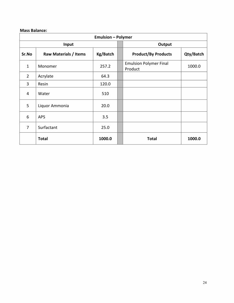
Mass Balance:
Emulsion – Polymer
Input Output
Sr.No Raw Materials / Items Kg/Batch Product/By Products Qty/Batch
1 Monomer 257.2 Emulsion Polymer Final
Product 1000.0
2 Acrylate 64.3
3 Resin 120.0
4 Water 510
5 Liquor Ammonia 20.0
6 APS 3.5
7 Surfactant 25.0
Total 1000.0 Total 1000.0
25
Step-1
Step-2
+
Phthalic Anhydride
M.W. 148.0
O
H2O CH3 NH2 + Methylation / H2O
N-Methyl Phthalimide
M.W. 161.0
C
Water
M.W. 18.0
C
O
O
Mono Methyl Amine
M.W. 31.0
O
C
C
O
N – CH3
HNO3 +
N-Methyl Phthalimide
M.W. 161.0
Nitric Acid
M.W. 63.0
O
O
N – CH3
C
C
H2SO4 +
Sulphuric Acid
M.W. 98.0
Nitration
O
O
N – CH3
C
C NO2
4-Nitro N-Methyl Phthalimide
M.W. 206.0
H2O
Water
M.W. 18.0
+
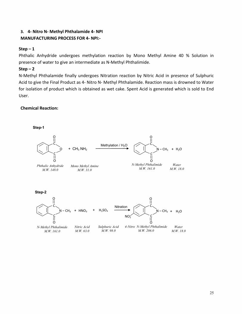
3. 4- Nitro N- Methyl Phthalamide 4- NPI
MANUFACTURING PROCESS FOR 4- NPI:-
Step – 1
Phthalic Anhydride undergoes methylation reaction by Mono Methyl Amine 40 % Solution in
presence of water to give an intermediate as N-Methyl PhthaIimide.
Step – 2
N-Methyl Phthalamide finally undergoes Nitration reaction by Nitric Acid in presence of Sulphuric
Acid to give the Final Product as 4- Nitro N- Methyl Phthalamide. Reaction mass is drowned to Water
for isolation of product which is obtained as wet cake. Spent Acid is generated which is sold to End
User.
Chemical Reaction:
26
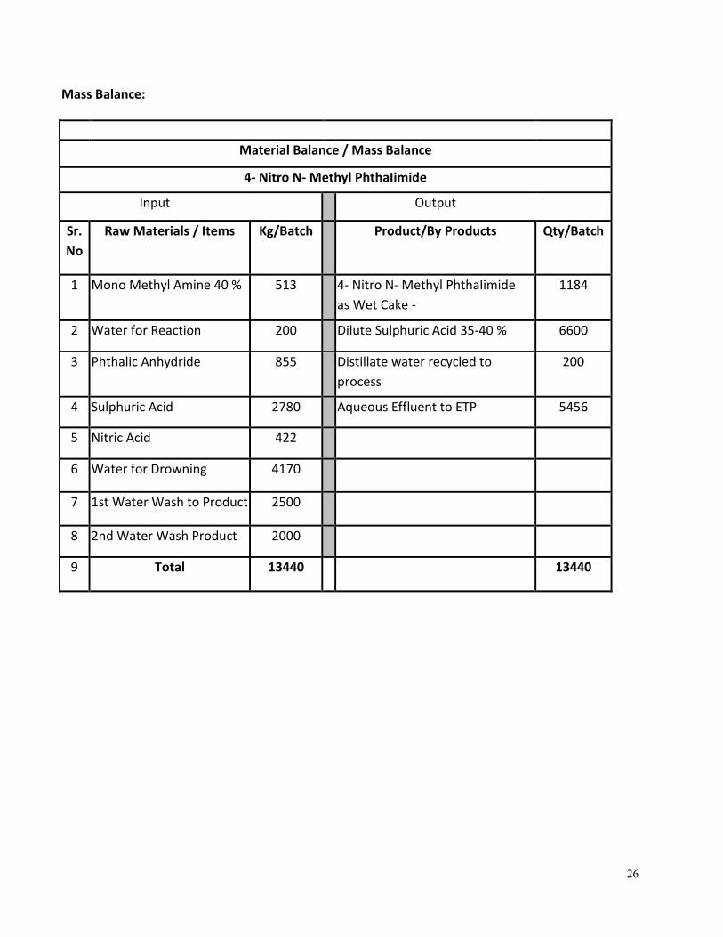
Mass Balance:
Material Balance / Mass Balance
4- Nitro N- Methyl PhthaIimide
Input Output
Sr.
No
Raw Materials / Items Kg/Batch Product/By Products Qty/Batch
1 Mono Methyl Amine 40 % 513 4- Nitro N- Methyl PhthaIimide
as Wet Cake -
1184
2 Water for Reaction 200 Dilute Sulphuric Acid 35-40 % 6600
3 Phthalic Anhydride 855 Distillate water recycled to
process
200
4 Sulphuric Acid 2780 Aqueous Effluent to ETP 5456
5 Nitric Acid 422
6 Water for Drowning 4170
7 1st Water Wash to Product 2500
8 2nd Water Wash Product 2000
9 Total 13440 13440
27
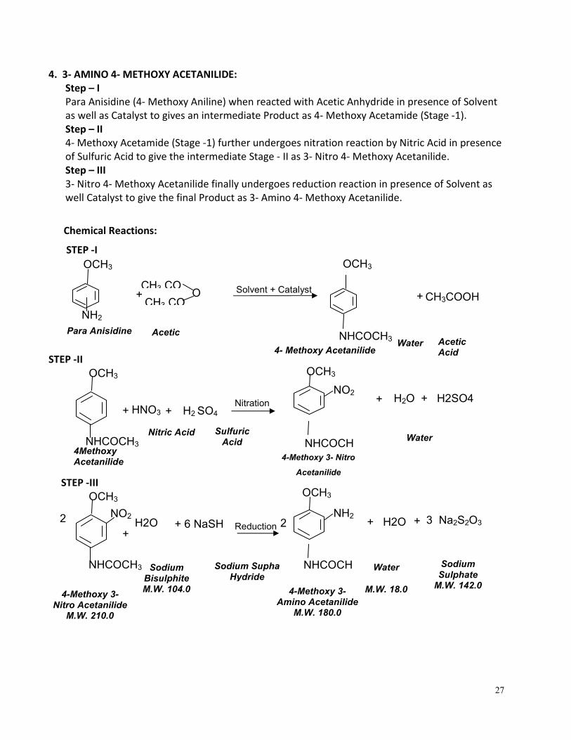
4. 3- AMINO 4- METHOXY ACETANILIDE:
Step – I
Para Anisidine (4- Methoxy Aniline) when reacted with Acetic Anhydride in presence of Solvent
as well as Catalyst to gives an intermediate Product as 4- Methoxy Acetamide (Stage -1).
Step – II
4- Methoxy Acetamide (Stage -1) further undergoes nitration reaction by Nitric Acid in presence
of Sulfuric Acid to give the intermediate Stage - II as 3- Nitro 4- Methoxy Acetanilide.
Step – III
3- Nitro 4- Methoxy Acetanilide finally undergoes reduction reaction in presence of Solvent as
well Catalyst to give the final Product as 3- Amino 4- Methoxy Acetanilide.
Chemical Reactions:
STEP -I
STEP -II
STEP -III
Solvent + Catalyst
CH3 CO +
Acetic Anhydride
Para Anisidine
M.W. 123.0
NH2
O CH3 CO
OCH3
4- Methoxy Acetanilide
NHCOCH3
OCH3
4Methoxy Acetanilide
NHCOCH3
OCH3
Nitration HNO3
+
Nitric Acid
H2 SO4
+
NO2
NHCOCH
Sulfuric Acid
H2O + H2SO4
+
OCH3
4-Methoxy 3- Nitro Acetanilide
M.W. 210.0
NHCOCH3
OCH3
Reduction
H2O +
+ 6 NaSH
NH2
NHCOCH
OCH3
NO2
4-Methoxy 3-Amino Acetanilide
M.W. 180.0
4-Methoxy 3- Nitro
Acetanilide
+ CH3COOH
Acetic Acid
Water
Water
Sodium Bisulphite M.W. 104.0
Sodium Supha Hydride
3 Na2S2O3
+
Sodium Sulphate
M.W. 142.0
Water
M.W. 18.0
2
2
+ H2O
28
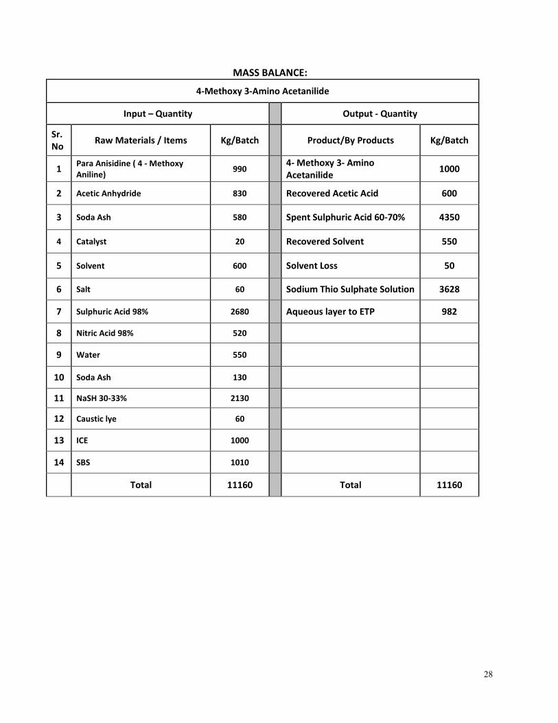
MASS BALANCE:
4-Methoxy 3-Amino Acetanilide
Input – Quantity Output - Quantity
Sr.
No Raw Materials / Items Kg/Batch Product/By Products Kg/Batch
1 Para Anisidine ( 4 - Methoxy
Aniline) 990
4- Methoxy 3- Amino
Acetanilide 1000
2 Acetic Anhydride 830 Recovered Acetic Acid 600
3 Soda Ash 580 Spent Sulphuric Acid 60-70% 4350
4 Catalyst 20 Recovered Solvent 550
5 Solvent 600 Solvent Loss 50
6 Salt 60 Sodium Thio Sulphate Solution 3628
7 Sulphuric Acid 98% 2680 Aqueous layer to ETP 982
8 Nitric Acid 98% 520
9 Water 550
10 Soda Ash 130
11 NaSH 30-33% 2130
12 Caustic lye 60
13 ICE 1000
14 SBS 1010
Total 11160 Total 11160
29
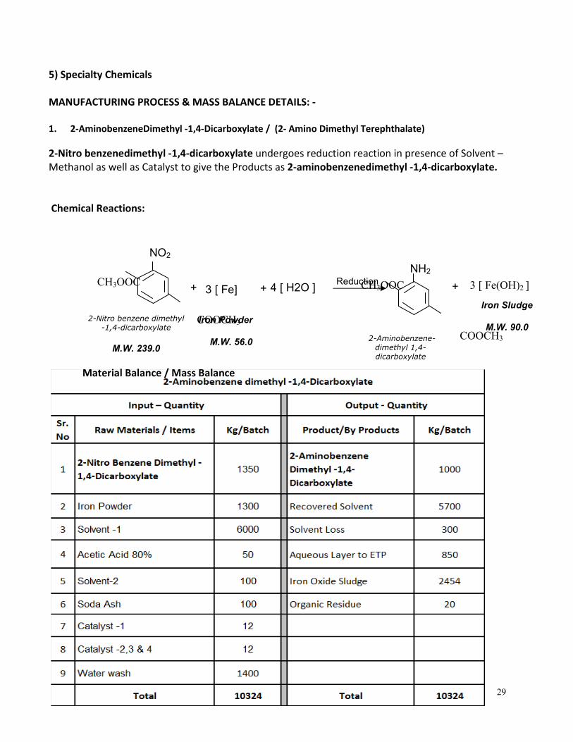
5) Specialty Chemicals
MANUFACTURING PROCESS & MASS BALANCE DETAILS: -
1. 2-AminobenzeneDimethyl -1,4-Dicarboxylate / (2- Amino Dimethyl Terephthalate)
2-Nitro benzenedimethyl -1,4-dicarboxylate undergoes reduction reaction in presence of Solvent –
Methanol as well as Catalyst to give the Products as 2-aminobenzenedimethyl -1,4-dicarboxylate.
Chemical Reactions:
Material Balance / Mass Balance
3 [ Fe(OH)2 ]
Reduction
3 [ Fe]
+
2-Nitro benzene dimethyl
-1,4-dicarboxylate
M.W. 239.0
NO2
COOCH3
CH3OOC
+
4 [ H2O ]
+
NH2
COOCH3
CH3OOC
2-Aminobenzene-
dimethyl 1,4-
dicarboxylate
Iron Powder
M.W. 56.0
Iron Sludge
M.W. 90.0
30
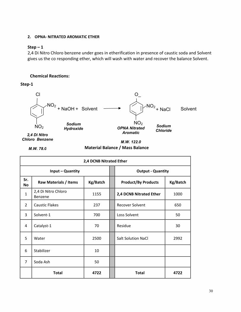
2. OPNA- NITRATED AROMATIC ETHER
Step – 1
2,4 Di Nitro Chloro benzene under goes in etherification in presence of caustic soda and Solvent
gives us the co responding ether, which will wash with water and recover the balance Solvent.
Chemical Reactions:
Step-1
Material Balance / Mass Balance
2,4 DCNB Nitrated Ether
Input – Quantity Output - Quantity
Sr.
No Raw Materials / Items Kg/Batch Product/By Products Kg/Batch
1 2,4 Di Nitro Chloro
Benzene 1155 2,4 DCNB Nitrated Ether 1000
2 Caustic Flakes 237 Recover Solvent 650
3 Solvent-1 700 Loss Solvent 50
4 Catalyst-1 70 Residue 30
5 Water 2500 Salt Solution NaCl 2992
6 Stabilizer 10
7 Soda Ash 50
Total 4722 Total 4722
NaOH
+
Sodium Hydroxide OPNA Nitrated
Aromatic
M.W. 122.0
2,4 Di Nitro Chloro Benzene
M.W. 78.0
NO2
NO2
Cl
Solvent
+
NO2
NO2
O_
Solvent
+ NaCl
Sodium Chloride
31
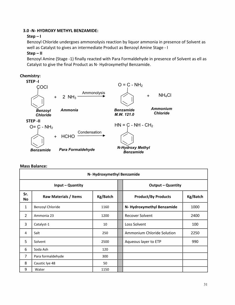
3.0 -N- HYDROXY METHYL BENZAMIDE:
Step – I
Benzoyl Chloride undergoes ammonolysis reaction by liquor ammonia in presence of Solvent as
well as Catalyst to gives an intermediate Product as Benzoyl Amine Stage - I
Step – II
Benzoyl Amine (Stage -1) finally reacted with Para Formaldehyde in presence of Solvent as ell as
Catalyst to give the final Product as N- Hydroxymethyl Benzamide.
Chemistry:
STEP -I
STEP -II
Mass Balance:
N- Hydroxymethyl Benzamide
Input – Quantity Output – Quantity
Sr.
No Raw Materials / Items Kg/Batch Product/By Products Kg/Batch
1 Benzoyl Chloride 1160 N- Hydroxymethyl Benzamide 1000
2 Ammonia 23 1200 Recover Solvent 2400
3 Catalyst-1 10 Loss Solvent 100
4 Salt 250 Ammonium Chloride Solution 2250
5 Solvent 2500 Aqueous layer to ETP 990
6 Soda Ash 120
7 Para formaldehyde 300
8 Caustic lye 48 50
9 Water 1150
Benzoyl Chloride
COCl Ammonolysis
2 NH3
+
Ammonia
O = C - NH2
NH4Cl +
Benzamide M.W. 121.0
Condensation
HCHO
+
Para Formaldehyde
HN = C - NH - CH2
N-Hydroxy Methyl Benzamide
O= C - NH2
Ammonium Chloride
Benzamide
32
Total 6740 Total 6740
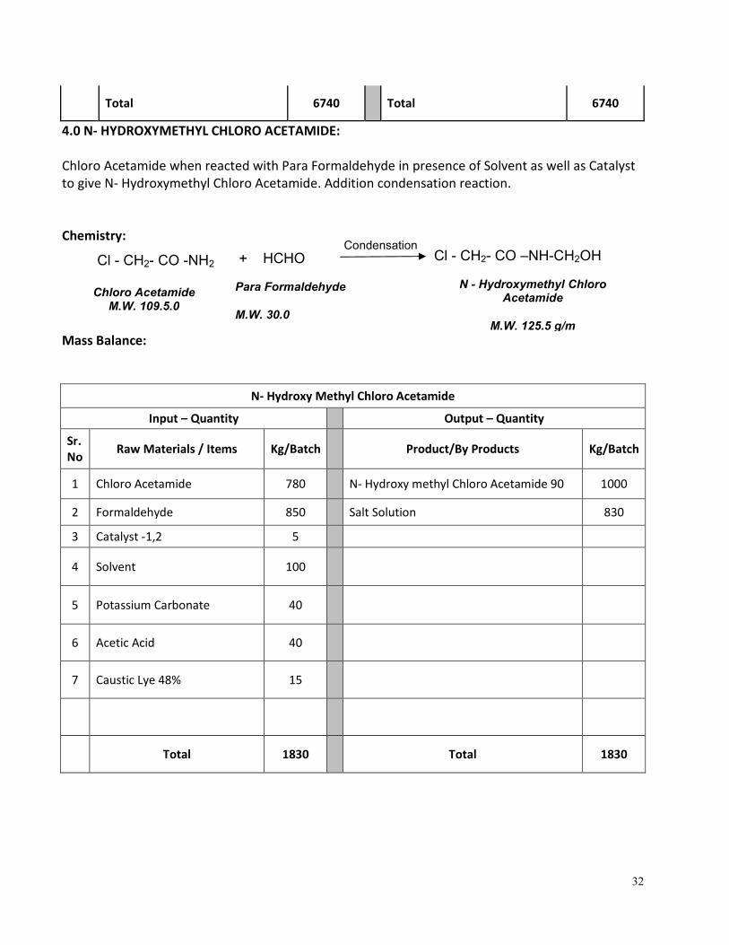
4.0 N- HYDROXYMETHYL CHLORO ACETAMIDE:
Chloro Acetamide when reacted with Para Formaldehyde in presence of Solvent as well as Catalyst
to give N- Hydroxymethyl Chloro Acetamide. Addition condensation reaction.
Chemistry:
Mass Balance:
N- Hydroxy Methyl Chloro Acetamide
Input – Quantity Output – Quantity
Sr.
No Raw Materials / Items Kg/Batch Product/By Products Kg/Batch
1 Chloro Acetamide 780 N- Hydroxy methyl Chloro Acetamide 90 1000
2 Formaldehyde 850 Salt Solution 830
3 Catalyst -1,2 5
4 Solvent 100
5 Potassium Carbonate 40
6 Acetic Acid 40
7 Caustic Lye 48% 15
Total 1830 Total 1830
Cl - CH2- CO -NH2
Chloro Acetamide M.W. 109.5.0
Condensation
HCHO
Para Formaldehyde
M.W. 30.0
+ Cl - CH2- CO –NH-CH2OH
N - Hydroxymethyl Chloro Acetamide
M.W. 125.5 g/m
33
Chemical Reactions:
Step-1:
Step-2:
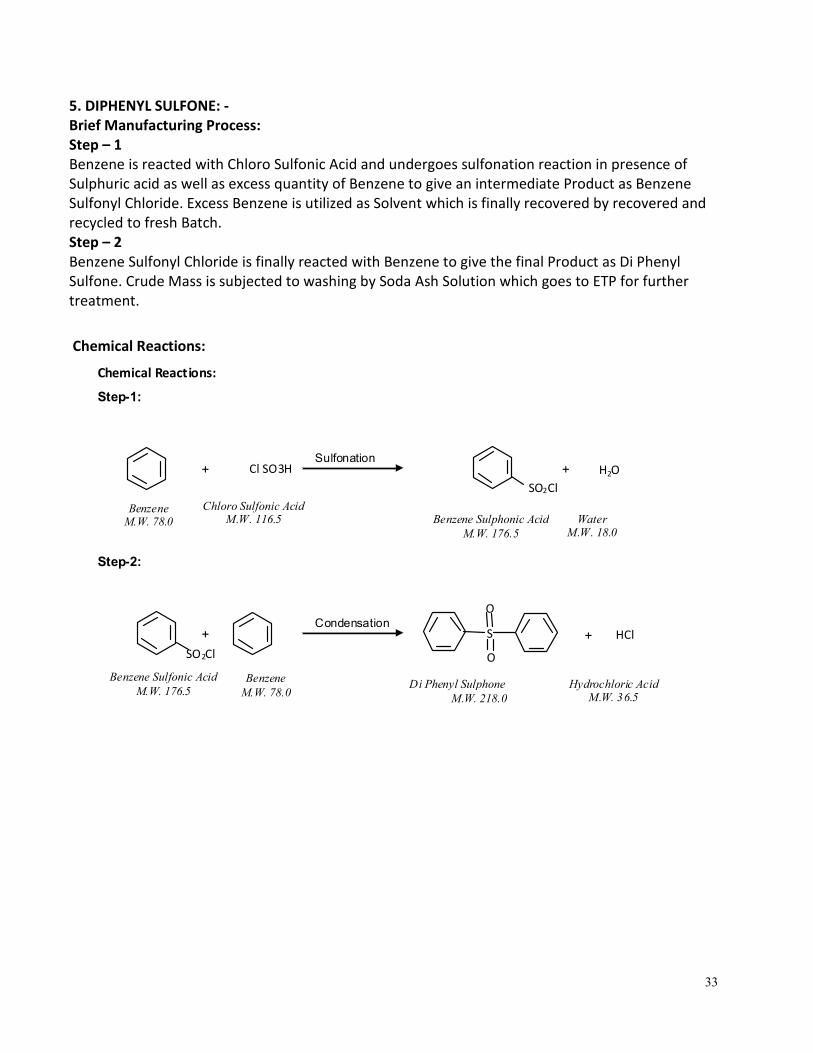
Sulfonation +
Chloro Sulfonic Acid M.W. 116.5
Benzene Sulphonic Acid
M.W. 176.5
Benzene M.W. 78.0
Cl SO3H + H2O
Water M.W. 18.0
SO2Cl
Condensation +
Benzene
M.W. 78.0
Di Phenyl Sulphone
M.W. 218.0
Benzene Sulfonic Acid
M.W. 176.5
+ HCl
Hydrochloric Acid M.W. 36.5
S
SO2Cl O
O
5. DIPHENYL SULFONE: -
Brief Manufacturing Process:
Step – 1
Benzene is reacted with Chloro Sulfonic Acid and undergoes sulfonation reaction in presence of
Sulphuric acid as well as excess quantity of Benzene to give an intermediate Product as Benzene
Sulfonyl Chloride. Excess Benzene is utilized as Solvent which is finally recovered by recovered and
recycled to fresh Batch.
Step – 2
Benzene Sulfonyl Chloride is finally reacted with Benzene to give the final Product as Di Phenyl
Sulfone. Crude Mass is subjected to washing by Soda Ash Solution which goes to ETP for further
treatment.
Chemical Reactions:
34
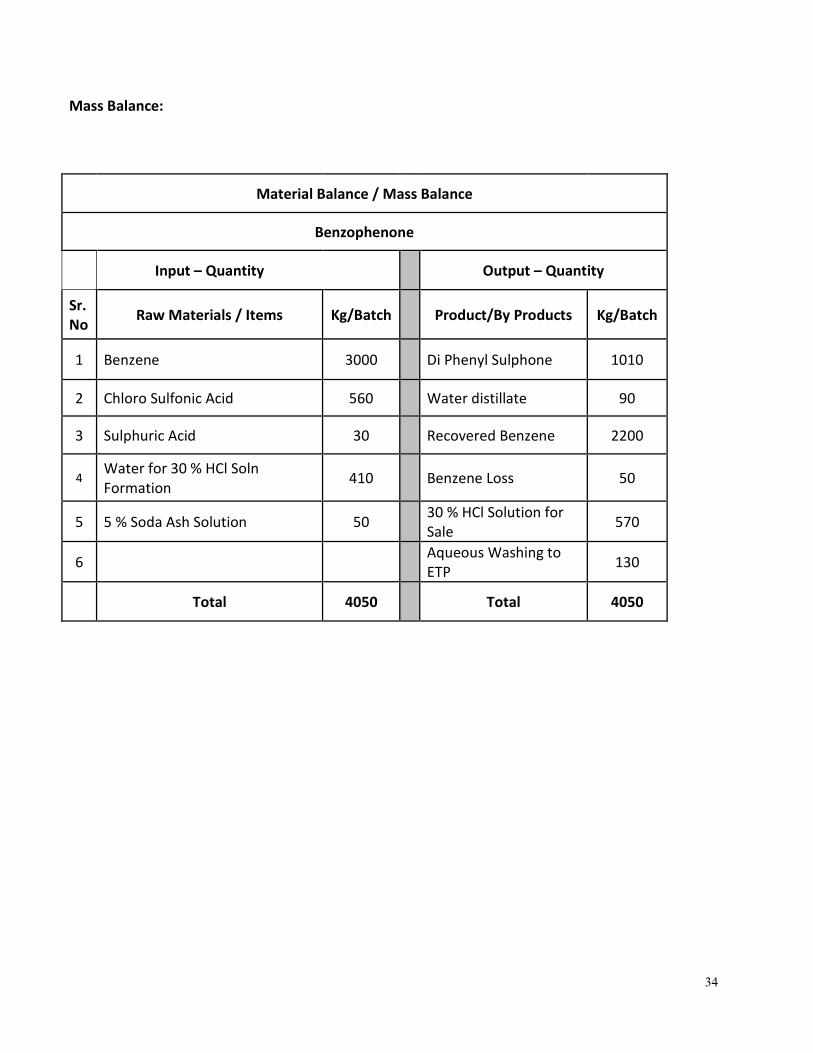
Mass Balance:
Material Balance / Mass Balance
Benzophenone
Input – Quantity Output – Quantity
Sr.
No Raw Materials / Items Kg/Batch Product/By Products Kg/Batch
1 Benzene 3000 Di Phenyl Sulphone 1010
2 Chloro Sulfonic Acid 560 Water distillate 90
3 Sulphuric Acid 30 Recovered Benzene 2200
4 Water for 30 % HCl Soln
Formation 410 Benzene Loss 50
5 5 % Soda Ash Solution 50 30 % HCl Solution for
Sale 570
6 Aqueous Washing to
ETP 130
Total 4050 Total 4050
35
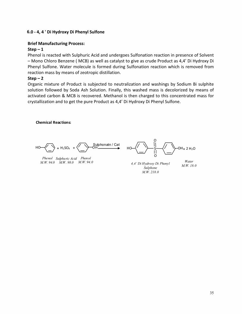
Chemical Reactions:
Sulphonatn / Cat +
Sulphuric Acid M.W. 98.0
4,4’ Di Hydroxy Di Phenyl
Sulphone
M.W. 218.0
Phenol
M.W. 94.0
+ 2 H2O
Water
M.W. 18.0
S H2SO4
O
O
HO HO OH OH +
Phenol M.W. 94.0
6.0 - 4, 4 ' Di Hydroxy Di Phenyl Sulfone
Brief Manufacturing Process:
Step – 1
Phenol is reacted with Sulphuric Acid and undergoes Sulfonation reaction in presence of Solvent
– Mono Chloro Benzene ( MCB) as well as catalyst to give as crude Product as 4,4’ Di Hydroxy Di
Phenyl Sulfone. Water molecule is formed during Sulfonation reaction which is removed from
reaction mass by means of zeotropic distillation.
Step – 2
Organic mixture of Product is subjected to neutralization and washings by Sodium Bi sulphite
solution followed by Soda Ash Solution. Finally, this washed mass is decolorized by means of
activated carbon & MCB is recovered. Methanol is then charged to this concentrated mass for
crystallization and to get the pure Product as 4,4’ Di Hydroxy Di Phenyl Sulfone.
36
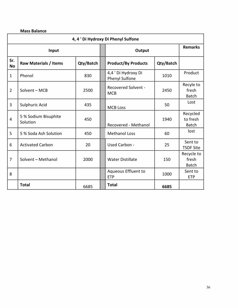
Mass Balance
4, 4 ' Di Hydroxy Di Phenyl Sulfone
Input Output Remarks
Sr.
No Raw Materials / Items Qty/Batch
Product/By Products Qty/Batch
1 Phenol 830
4,4 ' Di Hydroxy Di
Phenyl Sulfone 1010
Product
2 Solvent – MCB 2500
Recovered Solvent -
MCB 2450
Recyle to
fresh
Batch
3 Sulphuric Acid 435 MCB Loss
50 Lost
4 5 % Sodium Bisuphite
Solution 450
Recovered - Methanol
1940
Recycled
to fresh
Batch
5 5 % Soda Ash Solution 450
Methanol Loss 60 lost
6 Activated Carbon 20
Used Carbon - 25 Sent to
TSDF Site
7 Solvent – Methanol 2000 Water Distillate 150
Recycle to
fresh
Batch
8 Aqueous Effluent to
ETP 1000
Sent to
ETP
Total 6685
Total 6685
37
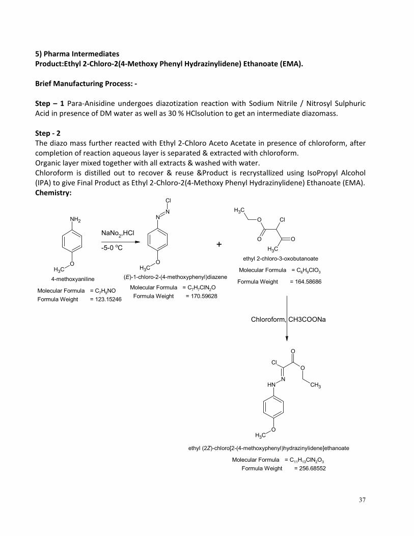
5) Pharma Intermediates
Product:Ethyl 2-Chloro-2(4-Methoxy Phenyl Hydrazinylidene) Ethanoate (EMA).
Brief Manufacturing Process: -
Step – 1 Para-Anisidine undergoes diazotization reaction with Sodium Nitrile / Nitrosyl Sulphuric
Acid in presence of DM water as well as 30 % HClsolution to get an intermediate diazomass.
Step - 2
The diazo mass further reacted with Ethyl 2-Chloro Aceto Acetate in presence of chloroform, after
completion of reaction aqueous layer is separated & extracted with chloroform.
Organic layer mixed together with all extracts & washed with water.
Chloroform is distilled out to recover & reuse &Product is recrystallized using IsoPropyl Alcohol
(IPA) to give Final Product as Ethyl 2-Chloro-2(4-Methoxy Phenyl Hydrazinylidene) Ethanoate (EMA).
Chemistry:
NH2
OCH3
N
OCH3
N
Cl
+
O
O
Cl
CH3
O
CH3
NH
OCH3
N
ClO
O
CH3
NaNo2,HCl
-5-0 oC
4-methoxyaniline (E)-1-chloro-2-(4-methoxyphenyl)diazene
ethyl (2Z)-chloro[2-(4-methoxyphenyl)hydrazinylidene]ethanoate
Molecular Formula = C7H9NOMolecular Formula = C7H7ClN2O
Molecular Formula = C11H13ClN2O3
Formula Weight = 123.15246Formula Weight = 170.59628
Formula Weight = 256.68552
ethyl 2-chloro-3-oxobutanoate
Molecular Formula = C6H9ClO3
Formula Weight = 164.58686
Chloroform, CH3COONa
38
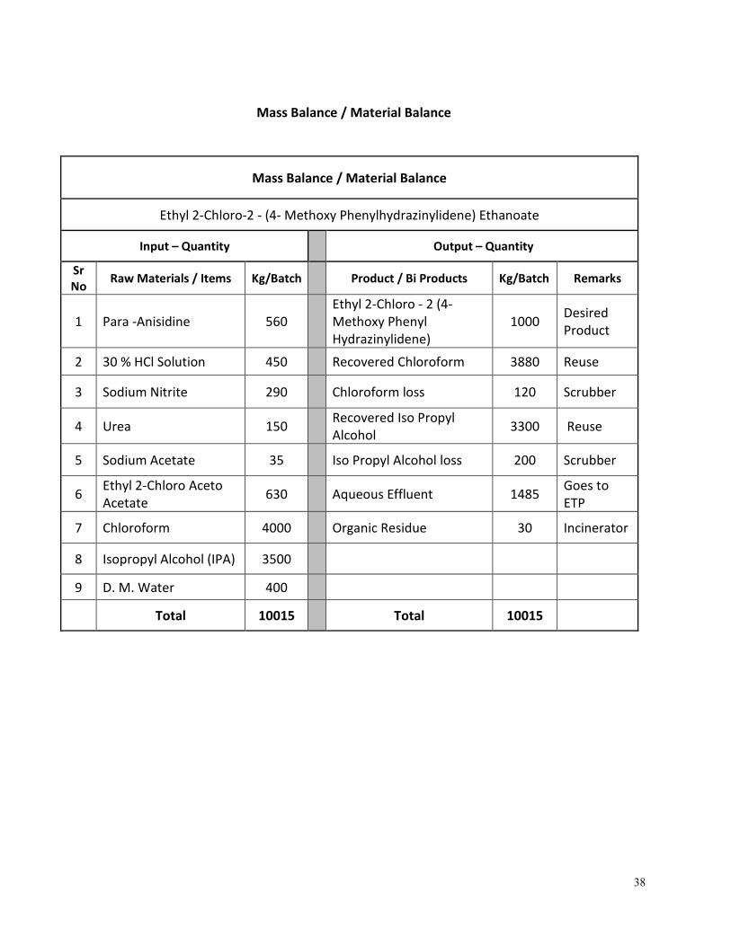
Mass Balance / Material Balance
Mass Balance / Material Balance
Ethyl 2-Chloro-2 - (4- Methoxy Phenylhydrazinylidene) Ethanoate
Input – Quantity Output – Quantity
Sr
No Raw Materials / Items Kg/Batch Product / Bi Products Kg/Batch Remarks
1 Para -Anisidine 560
Ethyl 2-Chloro - 2 (4-
Methoxy Phenyl
Hydrazinylidene)
1000 Desired
Product
2 30 % HCl Solution 450 Recovered Chloroform 3880 Reuse
3 Sodium Nitrite 290 Chloroform loss 120 Scrubber
4 Urea 150 Recovered Iso Propyl
Alcohol 3300 Reuse
5 Sodium Acetate 35 Iso Propyl Alcohol loss 200 Scrubber
6 Ethyl 2-Chloro Aceto
Acetate 630 Aqueous Effluent 1485
Goes to
ETP
7 Chloroform 4000 Organic Residue 30 Incinerator
8 Isopropyl Alcohol (IPA) 3500
9 D. M. Water 400
Total 10015 Total 10015
39
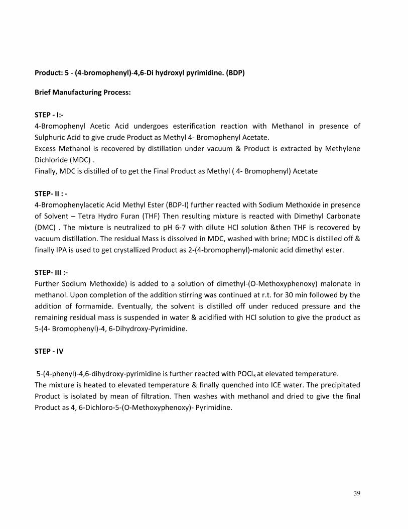
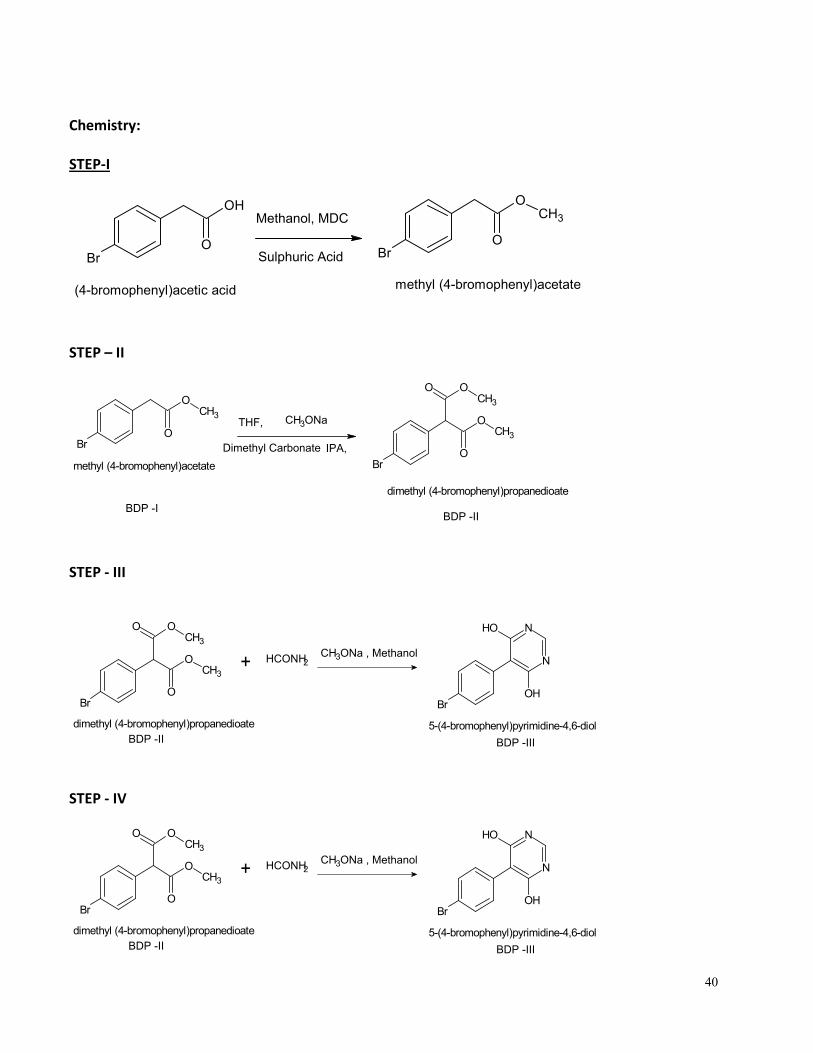
Product: 5 - (4-bromophenyl)-4,6-Di hydroxyl pyrimidine. (BDP)
Brief Manufacturing Process:
STEP - I:-
4-Bromophenyl Acetic Acid undergoes esterification reaction with Methanol in presence of
Sulphuric Acid to give crude Product as Methyl 4- Bromophenyl Acetate.
Excess Methanol is recovered by distillation under vacuum & Product is extracted by Methylene
Dichloride (MDC) .
Finally, MDC is distilled of to get the Final Product as Methyl ( 4- Bromophenyl) Acetate
STEP- II : -
4-Bromophenylacetic Acid Methyl Ester (BDP-I) further reacted with Sodium Methoxide in presence
of Solvent – Tetra Hydro Furan (THF) Then resulting mixture is reacted with Dimethyl Carbonate
(DMC) . The mixture is neutralized to pH 6-7 with dilute HCl solution &then THF is recovered by
vacuum distillation. The residual Mass is dissolved in MDC, washed with brine; MDC is distilled off &
finally IPA is used to get crystallized Product as 2-(4-bromophenyl)-malonic acid dimethyl ester.
STEP- III :-
Further Sodium Methoxide) is added to a solution of dimethyl-(O-Methoxyphenoxy) malonate in
methanol. Upon completion of the addition stirring was continued at r.t. for 30 min followed by the
addition of formamide. Eventually, the solvent is distilled off under reduced pressure and the
remaining residual mass is suspended in water & acidified with HCl solution to give the product as
5-(4- Bromophenyl)-4, 6-Dihydroxy-Pyrimidine.
STEP - IV
5-(4-phenyl)-4,6-dihydroxy-pyrimidine is further reacted with POCl3 at elevated temperature.
The mixture is heated to elevated temperature & finally quenched into ICE water. The precipitated
Product is isolated by mean of filtration. Then washes with methanol and dried to give the final
Product as 4, 6-Dichloro-5-(O-Methoxyphenoxy)- Pyrimidine.
40
Chemistry:
STEP-I
Br
OH
O
(4-bromophenyl)acetic acid
Br
O
O
CH3
methyl (4-bromophenyl)acetate
Sulphuric Acid
Methanol, MDC
STEP – II
Br
O
O
CH3
methyl (4-bromophenyl)acetate Br
O
O
CH3
OOCH3
dimethyl (4-bromophenyl)propanedioate
THF,
IPA,
CH3ONa
Dimethyl Carbonate
BDP -IBDP -II
STEP - III
Br
O
O
CH3
OOCH3
dimethyl (4-bromophenyl)propanedioate
Br
N
N
OH
OH
5-(4-bromophenyl)pyrimidine-4,6-diol
+ HCONH2
BDP -II BDP -III
CH3ONa , Methanol
STEP - IV
Br
O
O
CH3
OOCH3
dimethyl (4-bromophenyl)propanedioate
Br
N
N
OH
OH
5-(4-bromophenyl)pyrimidine-4,6-diol
+ HCONH2
BDP -II BDP -III
CH3ONa , Methanol
41
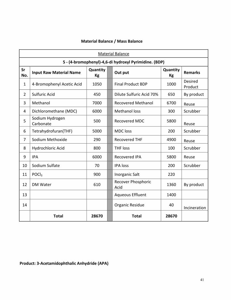
Material Balance / Mass Balance
Material Balance
5 - (4-bromophenyl)-4,6-di hydroxyl Pyrimidine. (BDP)
Sr
No. Input Raw Material Name
Quantity
Kg Out put
Quantity
Kg Remarks
1 4-Bromophenyl Acetic Acid 1050 Final Product BDP 1000 Desired
Product
2 Sulfuric Acid 450 Dilute Sulfuric Acid 70% 650 By product
3 Methanol 7000 Recovered Methanol 6700 Reuse
4 Dichloromethane (MDC) 6000 Methanol loss 300 Scrubber
5 Sodium Hydrogen
Carbonate 500 Recovered MDC 5800
Reuse
6 Tetrahydrofuran(THF) 5000 MDC loss 200 Scrubber
7 Sodium Methoxide 290 Recovered THF 4900 Reuse
8 Hydrochloric Acid 800 THF loss 100 Scrubber
9 IPA 6000 Recovered IPA 5800 Reuse
10 Sodium Sulfate 70 IPA loss 200 Scrubber
11 POCl3 900 Inorganic Salt 220
12 DM Water 610 Recover Phosphoric
Acid 1360 By product
13 Aqueous Effluent 1400
14 Organic Residue 40
Incineration
Total 28670 Total 28670
Product: 3-Acetamidophthalic Anhydride (APA)
42
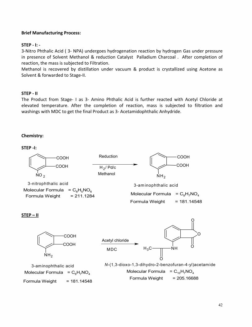
Brief Manufacturing Process:
STEP - I: -
3-Nitro Phthalic Acid ( 3- NPA) undergoes hydrogenation reaction by hydrogen Gas under pressure
in presence of Solvent Methanol & reduction Catalyst Palladium Charcoal . After completion of
reaction, the mass is subjected to Filtration.
Methanol is recovered by distillation under vacuum & product is crystallized using Acetone as
Solvent & forwarded to Stage-II.
STEP - II
The Product from Stage- I as 3- Amino Phthalic Acid is further reacted with Acetyl Chloride at
elevated temperature. After the completion of reaction, mass is subjected to filtration and
washings with MDC to get the final Product as 3- Acetamidophthalic Anhydride.
Chemistry:
STEP -I:
NO 2
COOH
COOH
3-nitrophthalic acid
Molecular Formula = C8H5NO6
Formula Weight = 211.1284
Reduction
H 2 / Pd/c
COOH
COOH
NH2
3-am inophthalic acid
Molecular Formula = C8H7NO4
Methanol
Formula Weight = 181.14548
STEP – II
COOH
COOH
NH2
3-am inophthalic acid
Molecular Formula = C8H7NO4
Formula Weight = 181.14548
Acetyl chloride
NH
O
CH3
O
O
O
N-(1,3-dioxo-1,3-dihydro-2-benzofuran-4-yl)acetamide
Molecular Formula = C10H7NO4
Formula Weight = 205.16688
MDC
43
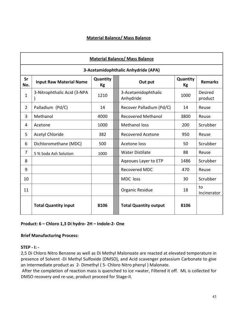
Material Balance/ Mass Balance
Material Balance/ Mass Balance
3-Acetamidophthalic Anhydride (APA)
Sr
No. Input Raw Material Name
Quantity
Kg Out put
Quantity
Kg Remarks
1 3-Nitrophthalic Acid (3-NPA
) 1210
3-Acetamidophthalic
Anhydride 1000
Desired
product
2 Palladium (Pd/C) 14 Recover Palladium (Pd/C) 14 Reuse
3 Methanol 4000 Recovered Methanol 3800 Reuse
4 Acetone 1000 Methanol loss 200 Scrubber
5 Acetyl Chloride 382 Recovered Acetone 950 Reuse
6 Dichloromethane (MDC) 500 Acetone loss 50 Scrubber
7 5 % Soda Ash Solution 1000 Water Distilate 88 Reuse
8 Aqeoues Layer to ETP 1486 Scrubber
9 Recovered MDC 470 Reuse
10 MDC loss 30 Scrubber
11
Organic Residue 18 to
Incinerator
Total Quantity input 8106 Total Quantity output 8106
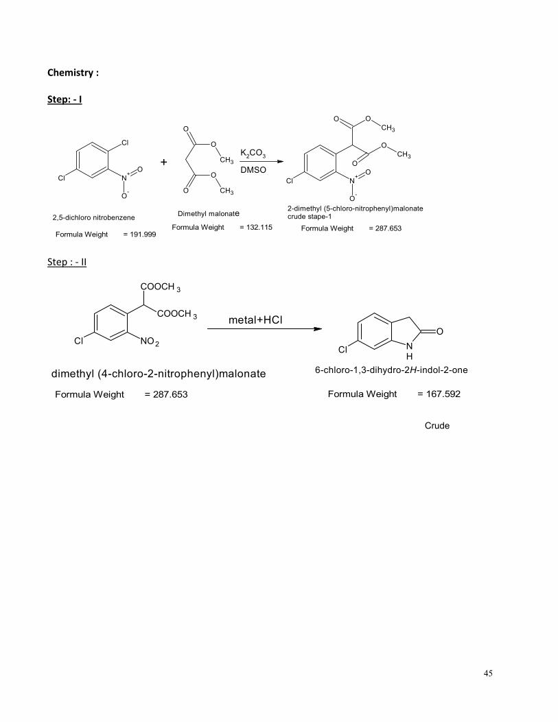
Product: 6 – Chloro 1,3 Di hydro- 2H – Indole-2- One
Brief Manufacturing Process:
STEP - I: -
2,5 Di Chloro Nitro Benzene as well as Di Methyl Malonoate are reacted at elevated temperature in
presence of Solvent -Di Methyl Sulfoxide (DMSO), and Acid scavenger potassium Carbonate to give
an intermediate product as 2- Dimethyl ( 5- Chloro Nitro phenyl ) Malonate.
After the completion of reaction mass is quenched to ice +water, Filtered it off. ML is collected for
DMSO recovery and re-use, product proceed for Stage-II.

44
STEP- II
2- Dimethyl ( 5- Chloro Nitro Phenyl ) Malonate (Satge – I) undergoes cyclization reaction in
presence of metal - catalyst as well as 30 % HCl Solution and water t to give the final product in
crude form
Crude product is further undergoes purification by using Ethyl Acetate as well as Activated Carbon
to obtain the final Product in Pure form. The ethyl acetate is recovered and re-used from the ML.
45
Chemistry :
Step: - I
Step : - II
Cl NO2
COOCH 3
COOCH 3
NH
O
Cl
dimethyl (4-chloro-2-nitrophenyl)malonate
metal+HCl
Formula Weight = 287.653 Formula Weight = 167.592
6-chloro-1,3-dihydro-2H-indol-2-one
Crude
Cl
Cl N+
O-
O+
O
O
O
O
CH3
CH3
K2CO
3
DMSO
Cl N+
O-
O
O
O
O
CH3
CH3
O
2,5-dichloro nitrobenzeneDimethyl malonate
2-dimethyl (5-chloro-nitrophenyl)malonatecrude stape-1
Formula Weight = 191.999Formula Weight = 132.115 Formula Weight = 287.653
46
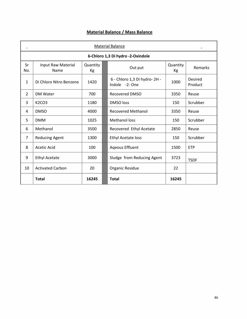
Material Balance / Mass Balance
Material Balance
6-Chloro 1,3 Di hydro -2-Oxindole
Sr
No.
Input Raw Material
Name
Quantity
Kg Out put
Quantity
Kg Remarks
1 Di Chloro Nitro Benzene 1420
6 - Chloro 1,3 Di hydro- 2H -
Indole -2- One 1000
Desired
Product
2 DM Water 700 Recovered DMSO 3350 Reuse
3 K2CO3 1180 DMSO loss 150 Scrubber
4 DMSO 4000 Recovered Methanol 3350 Reuse
5 DMM 1025 Methanol loss 150 Scrubber
6 Methanol 3500 Recovered Ethyl Acetate 2850 Reuse
7 Reducing Agent 1300 Ethyl Acetate loss 150 Scrubber
8 Acetic Acid 100
Aqeous Effluent 1500 ETP
9 Ethyl Acetate 3000
Sludge from Reducing Agent 3723 TSDF
10 Activated Carbon 20
Organic Residue 22
Total 16245 Total 16245
47
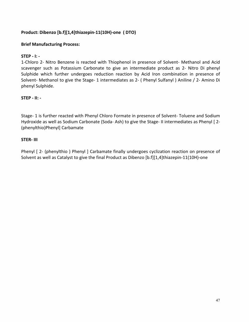
Product: Dibenzo [b.f][1,4]thiazepin-11(10H)-one ( DTO)
Brief Manufacturing Process:
STEP - I: -
1-Chloro 2- Nitro Benzene is reacted with Thiophenol in presence of Solvent- Methanol and Acid
scavenger such as Potassium Carbonate to give an intermediate product as 2- Nitro Di phenyl
Sulphide which further undergoes reduction reaction by Acid Iron combination in presence of
Solvent- Methanol to give the Stage- 1 intermediates as 2- ( Phenyl Sulfanyl ) Aniline / 2- Amino Di
phenyl Sulphide.
STEP - II: -
Stage- 1 is further reacted with Phenyl Chloro Formate in presence of Solvent- Toluene and Sodium
Hydroxide as well as Sodium Carbonate (Soda- Ash) to give the Stage- II intermediates as Phenyl [ 2-
(phenylthio)Phenyl] Carbamate
STER- III
Phenyl [ 2- (phenylthio ) Phenyl ] Carbamate finally undergoes cyclization reaction on presence of
Solvent as well as Catalyst to give the final Product as Dibenzo [b.f][1,4]thiazepin-11(10H)-one
48
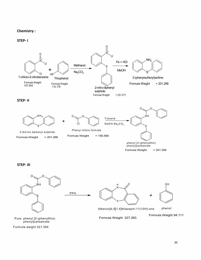
Chemistry :
STEP- I
STEP- II
STEP- III
Cl
N+
O-
O
+SH
Methanol
Na2CO3
1-chloro-2-nitrobenzene
Formula Weight 110.178
Thiophenol
Formula Weight 157.554
N+
O-
O
S
Formula Weight = 231.271
2-nitro-diphenyl sulphide
NH2
SMeOH
Fe + HCl
Formula Weight = 201.288
2-(phenylsulfanyl)aniline
NH2
S
2-Am ino diphenyl sulphide
OO
Cl
Phenyl chloro form ate
+Toluene
NaO H,Na2CO 3
NH
S
OO
phenyl [2-(phenylthio)phenyl]carbam ate
Formula Weight = 201.288Formula Weight = 156.566
Formula Weight = 321.394
NH
S
OO
Pure phenyl [2-(phenylthio)phenyl]carbam ate
PPA
NH
S
O
+
OH
Formula Weight 227.283
dibenzo[b,f][1,4]thiazepin-11(10H )-one
Formula Weight 94.111
phenol
Form ula weight 321.394
49
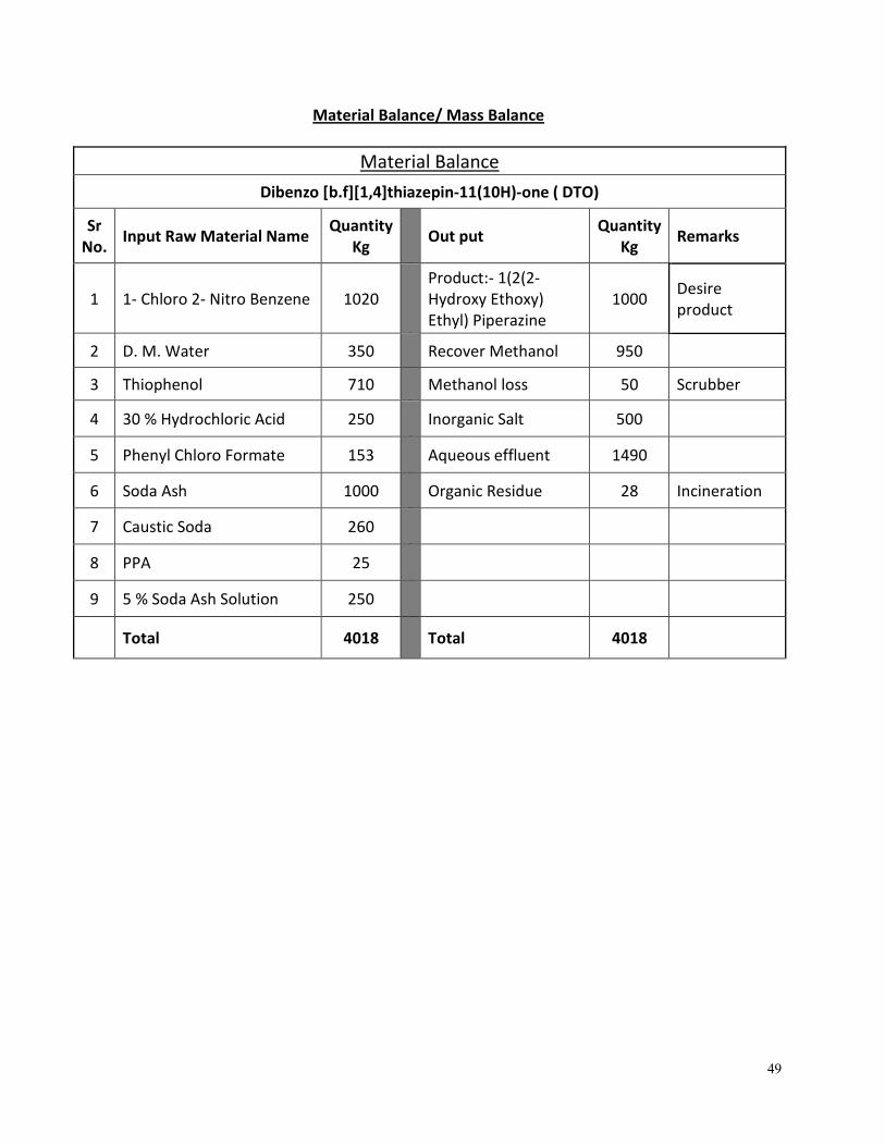
Material Balance/ Mass Balance
Material Balance
Dibenzo [b.f][1,4]thiazepin-11(10H)-one ( DTO)
Sr
No. Input Raw Material Name
Quantity
Kg Out put
Quantity
Kg Remarks
1 1- Chloro 2- Nitro Benzene 1020
Product:- 1(2(2-
Hydroxy Ethoxy)
Ethyl) Piperazine
1000 Desire
product
2 D. M. Water 350 Recover Methanol 950
3 Thiophenol 710 Methanol loss 50 Scrubber
4 30 % Hydrochloric Acid 250 Inorganic Salt 500
5 Phenyl Chloro Formate 153 Aqueous effluent 1490
6 Soda Ash 1000 Organic Residue 28 Incineration
7 Caustic Soda 260
8 PPA 25
9 5 % Soda Ash Solution 250
Total 4018 Total 4018
50
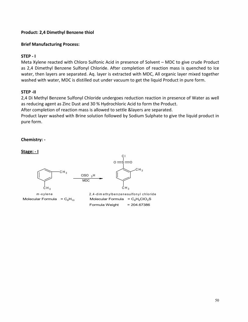
Product: 2,4 Dimethyl Benzene thiol
Brief Manufacturing Process:
STEP - I
Meta Xylene reacted with Chloro Sulfonic Acid in presence of Solvent – MDC to give crude Product
as 2,4 Dimethyl Benzene Sulfonyl Chloride. After completion of reaction mass is quenched to Ice
water, then layers are separated. Aq. layer is extracted with MDC, All organic layer mixed together
washed with water, MDC is distilled out under vacuum to get the liquid Product in pure form.
STEP -II
2,4 Di Methyl Benzene Sulfonyl Chloride undergoes reduction reaction in presence of Water as well
as reducing agent as Zinc Dust and 30 % Hydrochloric Acid to form the Product.
After completion of reaction mass is allowed to settle &layers are separated.
Product layer washed with Brine solution followed by Sodium Sulphate to give the liquid product in
pure form.
Chemistry: -
Stage: - I
C H 3
S OO
C l
C H 3
2 ,4 -d im e th y lb e n z e n e su lfo n y l c h lo r id e
C H 3
C H 3
m -x y le n e
ClSO 3 H
Molecular Formula = C8H10 Molecular Formula = C8H9ClO2S
Formula Weight = 204.67386
MDC
51
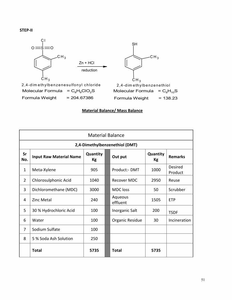
STEP-II
SH
C H 3
C H 3
2,4 -d im e thy lbenzene th io l
C H 3
S OO
C l
C H 3
2 ,4 -d im e thy lbenzenesu lfony l ch lo ride
Zn + HCl
reduction
Molecular Formula = C8H9ClO2S
Formula Weight = 204.67386
Molecular Formula = C8H10S
Formula Weight = 138.23
Material Balance/ Mass Balance
Material Balance
2,4-Dimethylbenzenethiol (DMT)
Sr
No. Input Raw Material Name
Quantity
Kg Out put
Quantity
Kg Remarks
1 Meta-Xylene 905
Product:- DMT 1000 Desired
Product
2 Chlorosulphonic Acid 1040 Recover MDC 2950 Reuse
3 Dichloromethane (MDC) 3000 MDC loss 50 Scrubber
4 Zinc Metal 240
Aqueous
effluent 1505 ETP
5 30 % Hydrochloric Acid 100
Inorganic Salt 200 TSDF
6 Water 100 Organic Residue 30 Incineration
7 Sodium Sulfate 100
8 5 % Soda Ash Solution 250
Total 5735 Total 5735
52
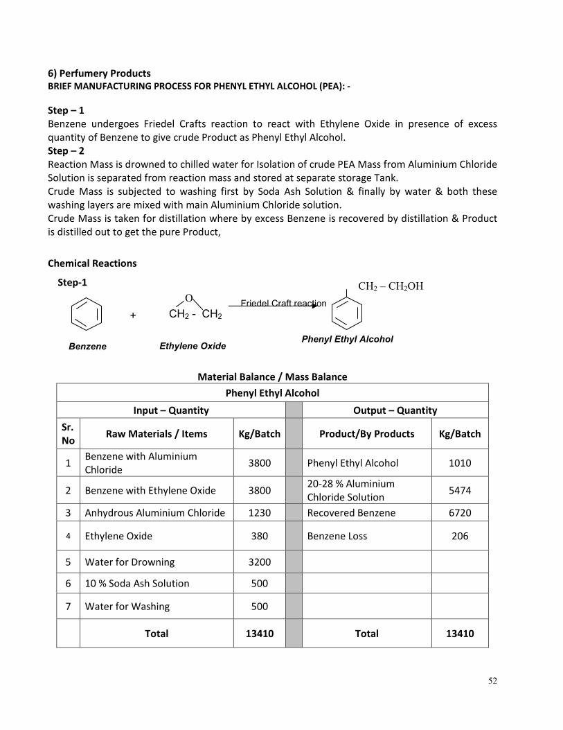
6) Perfumery Products BRIEF MANUFACTURING PROCESS FOR PHENYL ETHYL ALCOHOL (PEA): -
Step – 1
Benzene undergoes Friedel Crafts reaction to react with Ethylene Oxide in presence of excess
quantity of Benzene to give crude Product as Phenyl Ethyl Alcohol.
Step – 2
Reaction Mass is drowned to chilled water for Isolation of crude PEA Mass from Aluminium Chloride
Solution is separated from reaction mass and stored at separate storage Tank.
Crude Mass is subjected to washing first by Soda Ash Solution & finally by water & both these
washing layers are mixed with main Aluminium Chloride solution.
Crude Mass is taken for distillation where by excess Benzene is recovered by distillation & Product
is distilled out to get the pure Product,
Chemical Reactions
Step-1
Material Balance / Mass Balance
Phenyl Ethyl Alcohol
Input – Quantity Output – Quantity
Sr.
No Raw Materials / Items Kg/Batch Product/By Products Kg/Batch
1 Benzene with Aluminium
Chloride 3800 Phenyl Ethyl Alcohol 1010
2 Benzene with Ethylene Oxide 3800 20-28 % Aluminium
Chloride Solution 5474
3 Anhydrous Aluminium Chloride 1230 Recovered Benzene 6720
4 Ethylene Oxide 380 Benzene Loss 206
5 Water for Drowning 3200
6 10 % Soda Ash Solution 500
7 Water for Washing 500
Total 13410 Total 13410
CH2 – CH2OH
Friedel Craft reaction
CH2 - CH2
+
Ethylene Oxide Phenyl Ethyl Alcohol
Benzene
M.W. 78.0
O
53
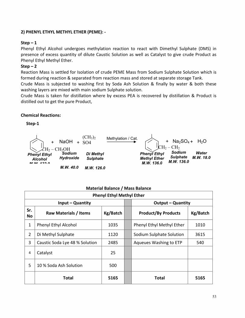
2) PHENYL ETHYL METHYL ETHER (PEME): -
Step – 1
Phenyl Ethyl Alcohol undergoes methylation reaction to react with Dimethyl Sulphate (DMS) in
presence of excess quantity of dilute Caustic Solution as well as Catalyst to give crude Product as
Phenyl Ethyl Methyl Ether.
Step – 2
Reaction Mass is settled for Isolation of crude PEME Mass from Sodium Sulphate Solution which is
formed during reaction & separated from reaction mass and stored at separate storage Tank.
Crude Mass is subjected to washing first by Soda Ash Solution & finally by water & both these
washing layers are mixed with main sodium Sulphate solution.
Crude Mass is taken for distillation where by excess PEA is recovered by distillation & Product is
distilled out to get the pure Product,
Chemical Reactions:
Step-1
Material Balance / Mass Balance
Phenyl Ethyl Methyl Ether
Input – Quantity Output – Quantity
Sr.
No Raw Materials / Items Kg/Batch Product/By Products Kg/Batch
1 Phenyl Ethyl Alcohol 1035 Phenyl Ethyl Methyl Ether 1010
2 Di Methyl Sulphate 1120 Sodium Sulphate Solution 3615
3 Caustic Soda Lye 48 % Solution 2485 Aqueues Washing to ETP 540
4 Catalyst 25
5 10 % Soda Ash Solution 500
Total 5165 Total 5165
CH2 – CH2
OCH
Methylation / Cat.
(CH3)2
SO4
+
Di Methyl Sulphate
M.W. 126.0
Phenyl Ethyl Methyl Ether M.W. 136.0
CH2 – CH2OH Phenyl Ethyl
Alcohol M.W. 122.0
NaOH
+
Na2SO4
+
Sodium Sulphate
M.W. 136.0
Sodium Hydroxide
M.W. 40.0
H2O
Water M.W. 18.0
+
54
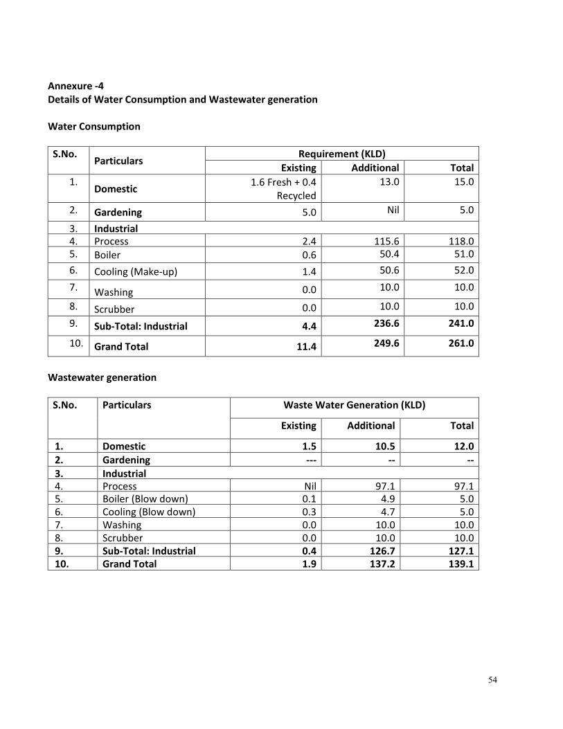
Annexure -4
Details of Water Consumption and Wastewater generation
Water Consumption
S.No. Particulars
Requirement (KLD)
Existing Additional Total
1. Domestic
1.6 Fresh + 0.4
Recycled
13.0 15.0
2. Gardening 5.0 Nil 5.0
3. Industrial
4. Process 2.4 115.6 118.0
5. Boiler 0.6 50.4 51.0
6. Cooling (Make-up) 1.4 50.6 52.0
7. Washing 0.0 10.0 10.0
8. Scrubber 0.0 10.0 10.0
9. Sub-Total: Industrial 4.4 236.6 241.0
10. Grand Total 11.4 249.6 261.0
Wastewater generation
S.No. Particulars Waste Water Generation (KLD)
Existing Additional Total
1. Domestic 1.5 10.5 12.0
2. Gardening --- -- --
3. Industrial
4. Process Nil 97.1 97.1
5. Boiler (Blow down) 0.1 4.9 5.0
6. Cooling (Blow down) 0.3 4.7 5.0
7. Washing 0.0 10.0 10.0
8. Scrubber 0.0 10.0 10.0
9. Sub-Total: Industrial 0.4 126.7 127.1
10. Grand Total 1.9 137.2 139.1
55
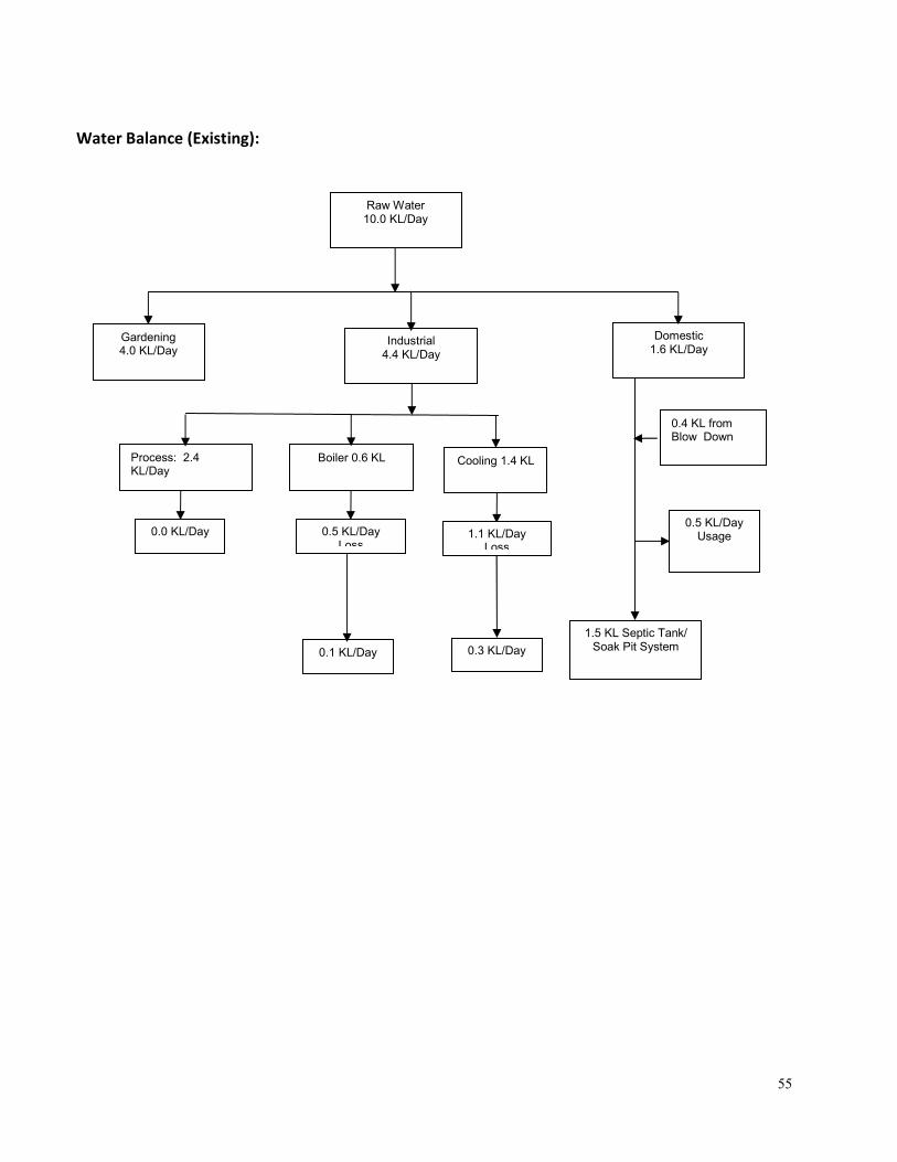
Water Balance (Existing):
Raw Water 10.0 KL/Day
Domestic 1.6 KL/Day
Industrial 4.4 KL/Day
Gardening 4.0 KL/Day
Process: 2.4 KL/Day
Boiler 0.6 KL Cooling 1.4 KL
1.5 KL Septic Tank/ Soak Pit System
0.4 KL from Blow Down
0.0 KL/Day
0.5 KL/Day Loss
0.5 KL/Day Usage
0.3 KL/Day
0.1 KL/Day
1.1 KL/Day Loss
56
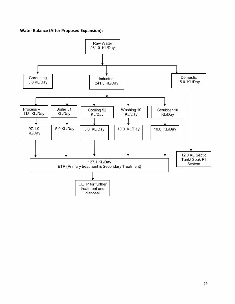
Water Balance (After Proposed Expansion):
Raw Water 261.0 KL/Day
Domestic 15.0 KL/Day
Industrial 241.0 KL/Day
Gardening 5.0 KL/Day
Process – 118 KL/Day
Boiler 51 KL/Day
Cooling 52 KL/Day
12.0 KL Septic Tank/ Soak Pit
System
97.1.0 KL/Day
5.0 KL/Day
127.1 KL/Day ETP (Primary treatment & Secondary Treatment)
5.0 KL/Day
CETP for further treatment and
disposal
Washing 10 KL/Day
10.0 KL/Day
Scrubber 10 KL/Day
10.0 KL/Day
57
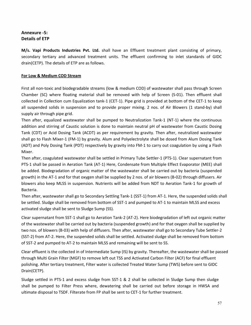
Annexure -5:
Details of ETP
M/s. Vapi Products Industries Pvt. Ltd. shall have an Effluent treatment plant consisting of primary,
secondary tertiary and advanced treatment units. The effluent confirming to inlet standards of GIDC
drain(CETP). The details of ETP are as follows.
For Low & Medium COD Stream
First all non-toxic and biodegradable streams (low & medium COD) of wastewater shall pass through Screen
Chamber (SC) where floating material shall be removed with help of Screen (S-01). Then effluent shall
collected in Collection cum Equalization tank-1 (CET-1). Pipe grid is provided at bottom of the CET-1 to keep
all suspended solids in suspension and to provide proper mixing. 2 nos. of Air Blowers (1 stand-by) shall
supply air through pipe grid.
Then after, equalized wastewater shall be pumped to Neutralization Tank-1 (NT-1) where the continuous
addition and stirring of Caustic solution is done to maintain neutral pH of wastewater from Caustic Dosing
Tank (CDT) or Acid Dosing Tank (ACDT) as per requirement by gravity. Then after, neutralized wastewater
shall go to Flash Mixer-1 (FM-1) by gravity. Alum and Polyelectrolyte shall be dosed from Alum Dosing Tank
(ADT) and Poly Dosing Tank (PDT) respectively by gravity into FM-1 to carry out coagulation by using a Flash
Mixer.
Then after, coagulated wastewater shall be settled in Primary Tube Settler-1 (PTS-1). Clear supernatant from
PTS-1 shall be passed in Aeration Tank (AT-1) Here, Condensate from Multiple Effect Evaporator (MEE) shall
be added. Biodegradation of organic matter of the wastewater shall be carried out by bacteria (suspended
growth) in the AT-1 and for that oxygen shall be supplied by 2 nos. of air blowers (B-02) through diffusers. Air
blowers also keep MLSS in suspension. Nutrients will be added from NDT to Aeration Tank-1 for growth of
Bacteria.
Then after, wastewater shall go to Secondary Settling Tank-1 (SST-1) from AT-1. Here, the suspended solids shall
be settled. Sludge shall be removed from bottom of SST-1 and pumped to AT-1 to maintain MLSS and excess
activated sludge shall be sent to Sludge Sump (SS).
Clear supernatant from SST-1 shall go to Aeration Tank-2 (AT-2). Here biodegradation of left out organic matter
of the wastewater shall be carried out by bacteria (suspended growth) and for that oxygen shall be supplied by
two nos. of blowers (B-03) with help of diffusers. Then after, wastewater shall go to Secondary Tube Settler-2
(SST-2) from AT-2. Here, the suspended solids shall be settled. Activated sludge shall be removed from bottom
of SST-2 and pumped to AT-2 to maintain MLSS and remaining will be sent to SS.
Clear effluent is the collected in of Intermediate Sump (IS) by gravity. Thereafter, the wastewater shall be passed
through Multi Grain Filter (MGF) to remove left out TSS and Activated Carbon Filter (ACF) for final effluent
polishing. After tertiary treatment, Filter water is collected Treated Water Sump (TWS) before sent to GIDC
Drain(CETP).
Sludge settled in PTS-1 and excess sludge from SST-1 & 2 shall be collected in Sludge Sump then sludge
shall be pumped to Filter Press where, dewatering shall be carried out before storage in HWSA and
ultimate disposal to TSDF. Filterate from FP shall be sent to CET-1 for further treatment.
58
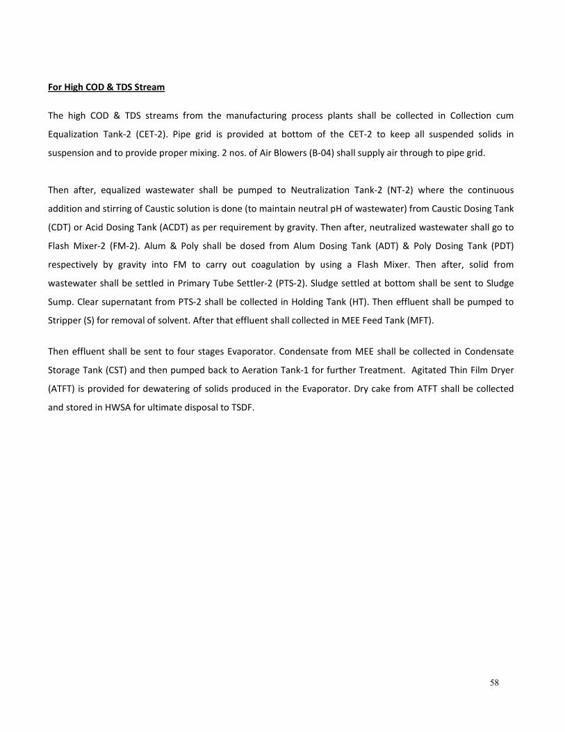
For High COD & TDS Stream
The high COD & TDS streams from the manufacturing process plants shall be collected in Collection cum
Equalization Tank-2 (CET-2). Pipe grid is provided at bottom of the CET-2 to keep all suspended solids in
suspension and to provide proper mixing. 2 nos. of Air Blowers (B-04) shall supply air through to pipe grid.
Then after, equalized wastewater shall be pumped to Neutralization Tank-2 (NT-2) where the continuous
addition and stirring of Caustic solution is done (to maintain neutral pH of wastewater) from Caustic Dosing Tank
(CDT) or Acid Dosing Tank (ACDT) as per requirement by gravity. Then after, neutralized wastewater shall go to
Flash Mixer-2 (FM-2). Alum & Poly shall be dosed from Alum Dosing Tank (ADT) & Poly Dosing Tank (PDT)
respectively by gravity into FM to carry out coagulation by using a Flash Mixer. Then after, solid from
wastewater shall be settled in Primary Tube Settler-2 (PTS-2). Sludge settled at bottom shall be sent to Sludge
Sump. Clear supernatant from PTS-2 shall be collected in Holding Tank (HT). Then effluent shall be pumped to
Stripper (S) for removal of solvent. After that effluent shall collected in MEE Feed Tank (MFT).
Then effluent shall be sent to four stages Evaporator. Condensate from MEE shall be collected in Condensate
Storage Tank (CST) and then pumped back to Aeration Tank-1 for further Treatment. Agitated Thin Film Dryer
(ATFT) is provided for dewatering of solids produced in the Evaporator. Dry cake from ATFT shall be collected
and stored in HWSA for ultimate disposal to TSDF.
59
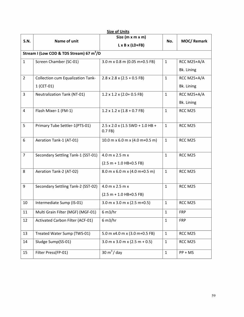
Size of Units
S.N. Name of unit Size (m x m x m)
L x B x (LD+FB) No. MOC/ Remark
Stream I (Low COD & TDS Stream) 67 m3/D
1 Screen Chamber (SC-01) 3.0 m x 0.8 m (0.05 m+0.5 FB) 1 RCC M25+A/A
Bk. Lining
2 Collection cum Equalization Tank-
1 (CET-01)
2.8 x 2.8 x (2.5 + 0.5 FB) 1 RCC M25+A/A
Bk. Lining
3 Neutralization Tank (NT-01) 1.2 x 1.2 x (2.0+ 0.5 FB) 1 RCC M25+A/A
Bk. Lining
4 Flash Mixer-1 (FM-1) 1.2 x 1.2 x (1.8 + 0.7 FB) 1 RCC M25
5 Primary Tube Settler-1(PTS-01) 2.5 x 2.0 x (1.5 SWD + 1.0 HB +
0.7 FB)
1 RCC M25
6 Aeration Tank-1 (AT-01) 10.0 m x 6.0 m x (4.0 m+0.5 m) 1 RCC M25
7 Secondary Settling Tank-1 (SST-01) 4.0 m x 2.5 m x
(2.5 m + 1.0 HB+0.5 FB)
1 RCC M25
8 Aeration Tank-2 (AT-02) 8.0 m x 6.0 m x (4.0 m+0.5 m) 1 RCC M25
9 Secondary Settling Tank-2 (SST-02) 4.0 m x 2.5 m x
(2.5 m + 1.0 HB+0.5 FB)
1 RCC M25
10 Intermediate Sump (IS-01) 3.0 m x 3.0 m x (2.5 m+0.5) 1 RCC M25
11 Multi Grain Filter (MGF) (MGF-01) 6 m3/hr 1 FRP
12 Activated Carbon Filter (ACF-01) 6 m3/hr 1 FRP
13 Treated Water Sump (TWS-01) 5.0 m x4.0 m x (3.0 m+0.5 FB) 1 RCC M25
14 Sludge Sump(SS-01) 3.0 m x 3.0 m x (2.5 m + 0.5) 1 RCC M25
15 Filter Press(FP-01) 30 m3
/ day 1 PP + MS
60
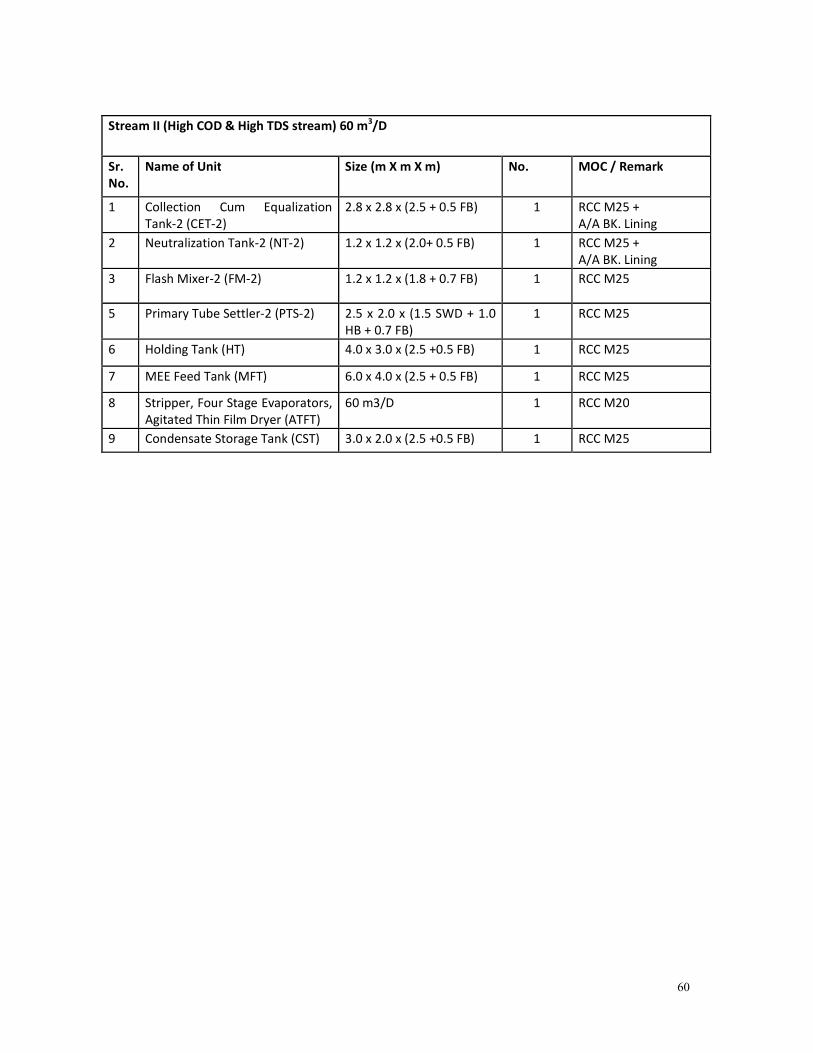
Stream II (High COD & High TDS stream) 60 m3/D
Sr.
No.
Name of Unit Size (m X m X m) No.
MOC / Remark
1 Collection Cum Equalization
Tank-2 (CET-2)
2.8 x 2.8 x (2.5 + 0.5 FB) 1 RCC M25 +
A/A BK. Lining
2 Neutralization Tank-2 (NT-2) 1.2 x 1.2 x (2.0+ 0.5 FB) 1 RCC M25 +
A/A BK. Lining
3 Flash Mixer-2 (FM-2) 1.2 x 1.2 x (1.8 + 0.7 FB) 1 RCC M25
5 Primary Tube Settler-2 (PTS-2) 2.5 x 2.0 x (1.5 SWD + 1.0
HB + 0.7 FB)
1 RCC M25
6 Holding Tank (HT) 4.0 x 3.0 x (2.5 +0.5 FB) 1 RCC M25
7 MEE Feed Tank (MFT) 6.0 x 4.0 x (2.5 + 0.5 FB) 1 RCC M25
8 Stripper, Four Stage Evaporators,
Agitated Thin Film Dryer (ATFT)
60 m3/D 1 RCC M20
9 Condensate Storage Tank (CST) 3.0 x 2.0 x (2.5 +0.5 FB) 1 RCC M25
61
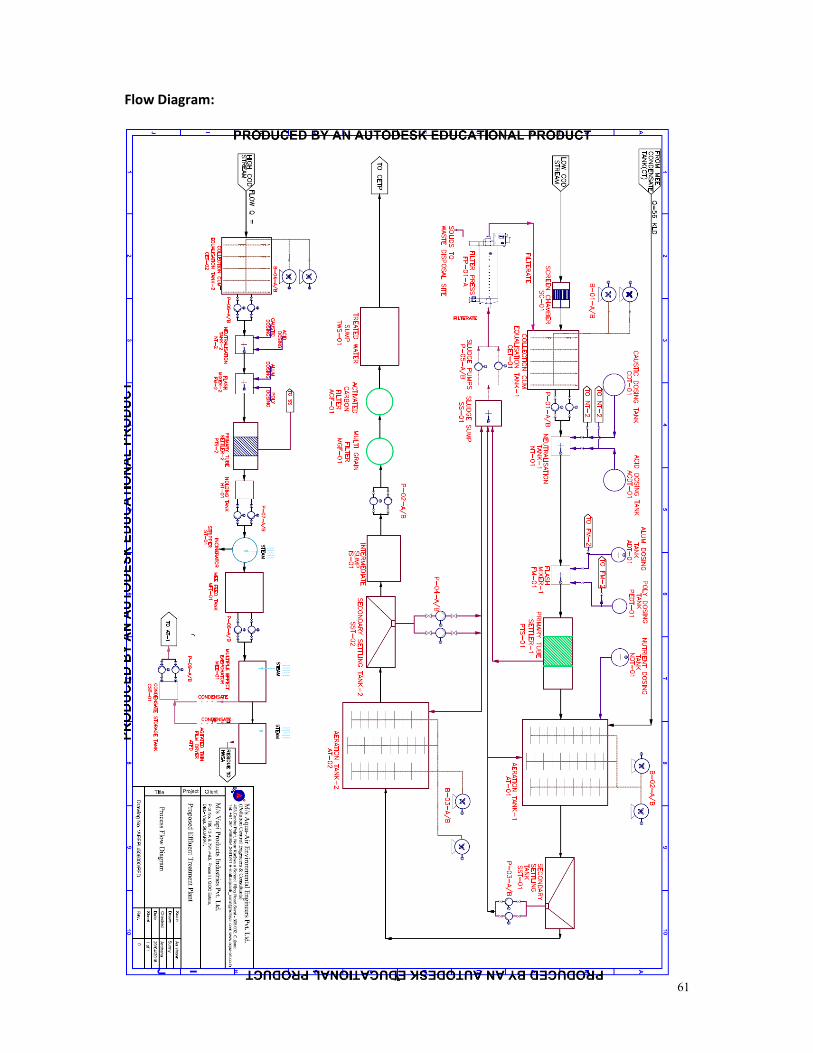
Flow Diagram:
62
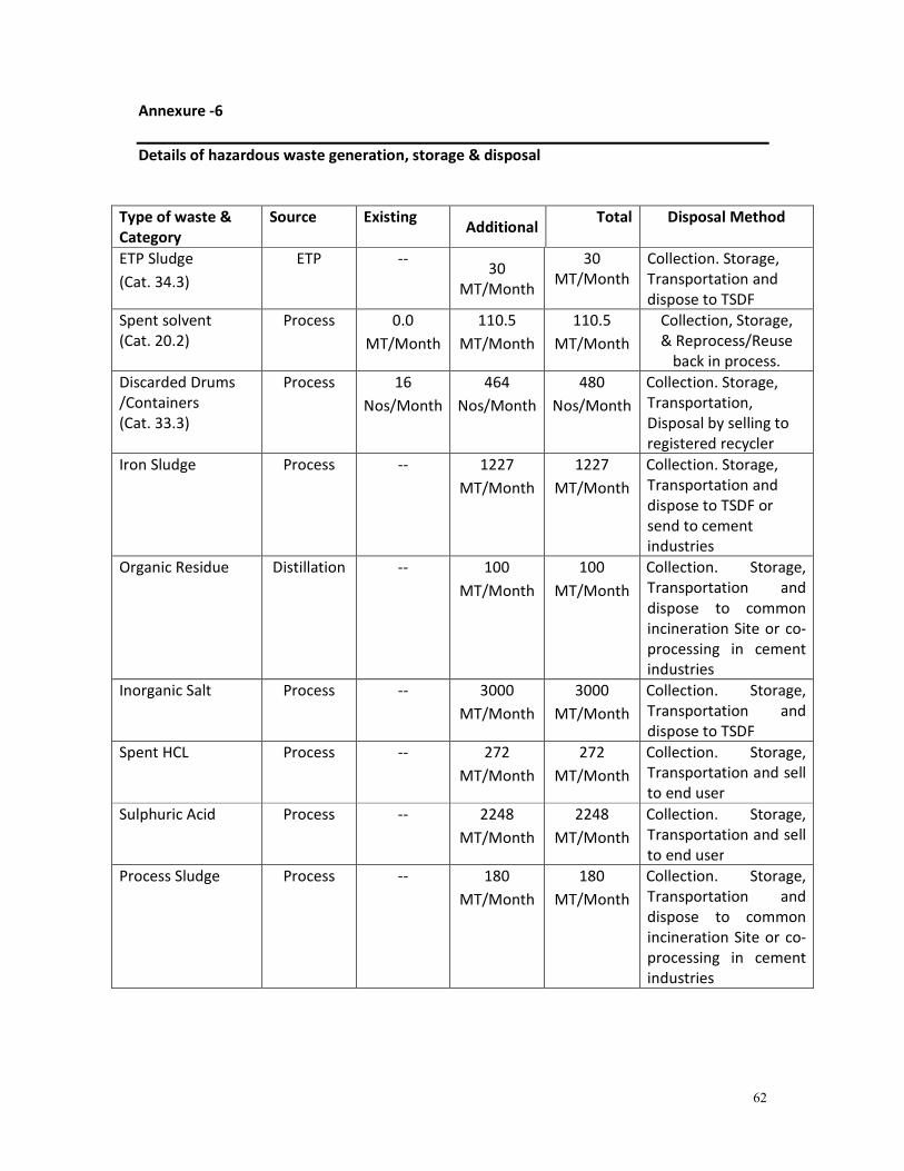
Annexure -6
Details of hazardous waste generation, storage & disposal
Type of waste &
Category
Source Existing Additional
Total Disposal Method
ETP Sludge
(Cat. 34.3)
ETP -- 30
MT/Month
30
MT/Month
Collection. Storage,
Transportation and
dispose to TSDF
Spent solvent
(Cat. 20.2)
Process 0.0
MT/Month
110.5
MT/Month
110.5
MT/Month
Collection, Storage,
& Reprocess/Reuse
back in process.
Discarded Drums
/Containers
(Cat. 33.3)
Process 16
Nos/Month
464
Nos/Month
480
Nos/Month
Collection. Storage,
Transportation,
Disposal by selling to
registered recycler
Iron Sludge Process -- 1227
MT/Month
1227
MT/Month
Collection. Storage,
Transportation and
dispose to TSDF or
send to cement
industries
Organic Residue Distillation -- 100
MT/Month
100
MT/Month
Collection. Storage,
Transportation and
dispose to common
incineration Site or co-
processing in cement
industries
Inorganic Salt Process -- 3000
MT/Month
3000
MT/Month
Collection. Storage,
Transportation and
dispose to TSDF
Spent HCL Process -- 272
MT/Month
272
MT/Month
Collection. Storage,
Transportation and sell
to end user
Sulphuric Acid Process -- 2248
MT/Month
2248
MT/Month
Collection. Storage,
Transportation and sell
to end user
Process Sludge Process -- 180
MT/Month
180
MT/Month
Collection. Storage,
Transportation and
dispose to common
incineration Site or co-
processing in cement
industries
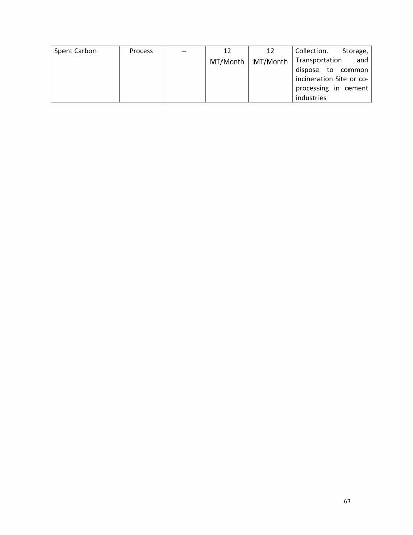
63
Spent Carbon Process -- 12
MT/Month
12
MT/Month
Collection. Storage,
Transportation and
dispose to common
incineration Site or co-
processing in cement
industries
64
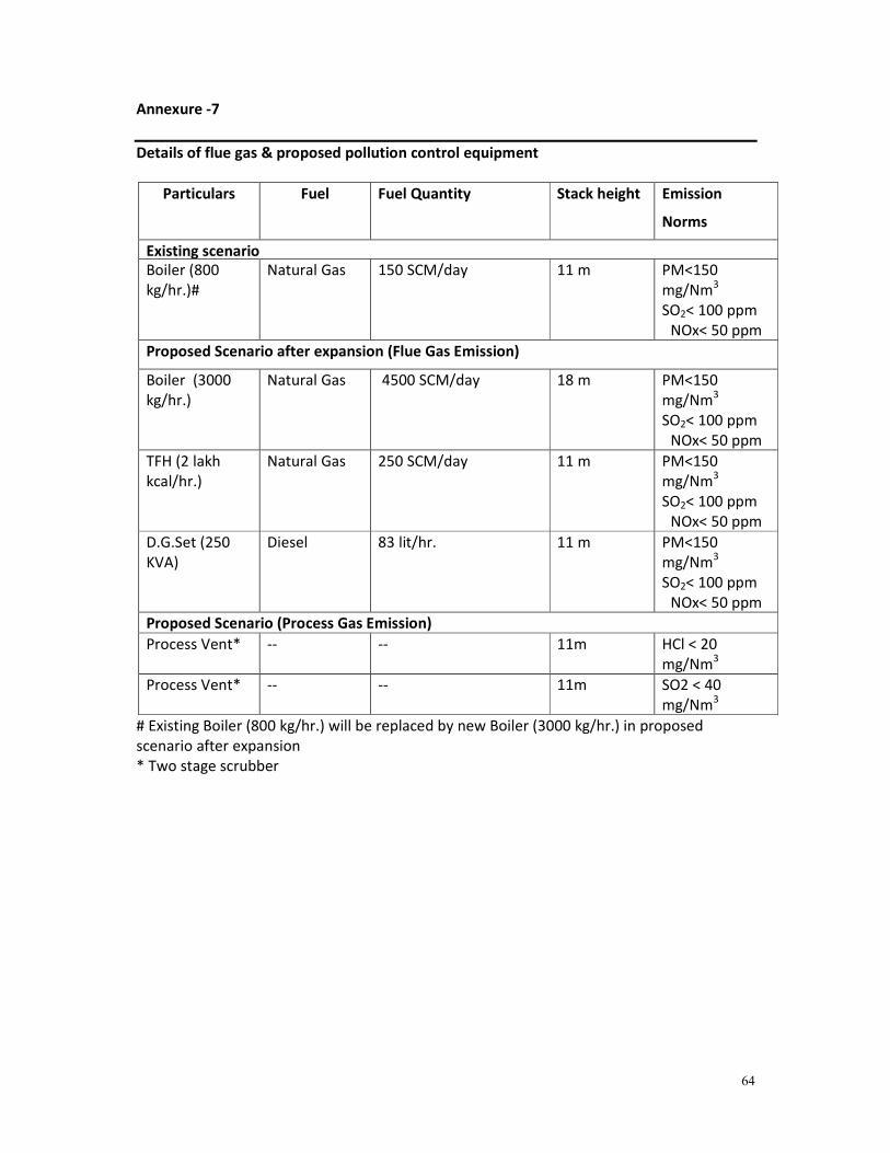
Annexure -7
Details of flue gas & proposed pollution control equipment
Particulars Fuel Fuel Quantity Stack height Emission
Norms
Existing scenario
Boiler (800
kg/hr.)#
Natural Gas 150 SCM/day 11 m PM<150
mg/Nm3
SO2< 100 ppm
NOx< 50 ppm
Proposed Scenario after expansion (Flue Gas Emission)
Boiler (3000
kg/hr.)
Natural Gas 4500 SCM/day 18 m PM<150
mg/Nm3
SO2< 100 ppm
NOx< 50 ppm
TFH (2 lakh
kcal/hr.)
Natural Gas 250 SCM/day 11 m PM<150
mg/Nm3
SO2< 100 ppm
NOx< 50 ppm
D.G.Set (250
KVA)
Diesel 83 lit/hr. 11 m PM<150
mg/Nm3
SO2< 100 ppm
NOx< 50 ppm
Proposed Scenario (Process Gas Emission)
Process Vent* -- -- 11m HCl < 20
mg/Nm3
Process Vent* -- -- 11m SO2 < 40
mg/Nm3
# Existing Boiler (800 kg/hr.) will be replaced by new Boiler (3000 kg/hr.) in proposed
scenario after expansion
* Two stage scrubber
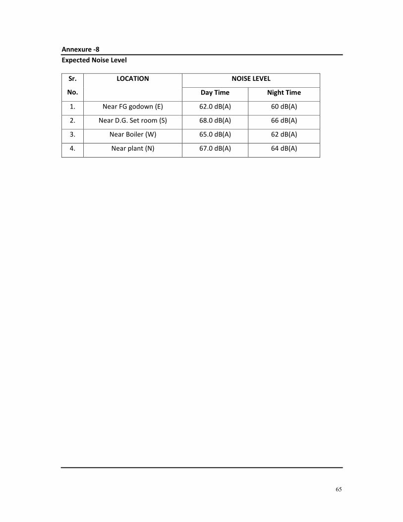
65
Annexure -8
Expected Noise Level
Sr.
No.
LOCATION NOISE LEVEL
Day Time Night Time
1. Near FG godown (E) 62.0 dB(A) 60 dB(A)
2. Near D.G. Set room (S) 68.0 dB(A) 66 dB(A)
3. Near Boiler (W) 65.0 dB(A) 62 dB(A)
4. Near plant (N) 67.0 dB(A) 64 dB(A)
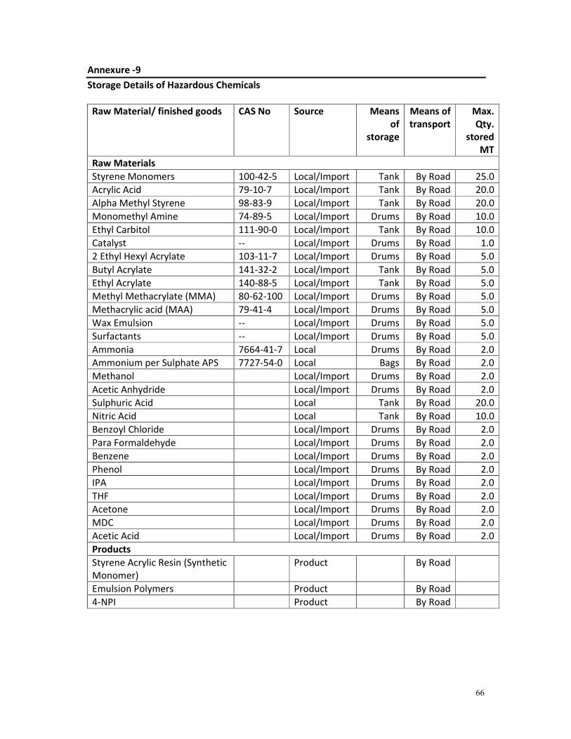
66
Annexure -9
Storage Details of Hazardous Chemicals
Raw Material/ finished goods CAS No Source Means
of
storage
Means of
transport
Max.
Qty.
stored
MT
Raw Materials
Styrene Monomers 100-42-5 Local/Import Tank By Road 25.0
Acrylic Acid 79-10-7 Local/Import Tank By Road 20.0
Alpha Methyl Styrene 98-83-9 Local/Import Tank By Road 20.0
Monomethyl Amine 74-89-5 Local/Import Drums By Road 10.0
Ethyl Carbitol 111-90-0 Local/Import Tank By Road 10.0
Catalyst -- Local/Import Drums By Road 1.0
2 Ethyl Hexyl Acrylate 103-11-7 Local/Import Drums By Road 5.0
Butyl Acrylate 141-32-2 Local/Import Tank By Road 5.0
Ethyl Acrylate 140-88-5 Local/Import Tank By Road 5.0
Methyl Methacrylate (MMA) 80-62-100 Local/Import Drums By Road 5.0
Methacrylic acid (MAA) 79-41-4 Local/Import Drums By Road 5.0
Wax Emulsion -- Local/Import Drums By Road 5.0
Surfactants -- Local/Import Drums By Road 5.0
Ammonia 7664-41-7 Local Drums By Road 2.0
Ammonium per Sulphate APS 7727-54-0 Local Bags By Road 2.0
Methanol Local/Import Drums By Road 2.0
Acetic Anhydride Local/Import Drums By Road 2.0
Sulphuric Acid Local Tank By Road 20.0
Nitric Acid Local Tank By Road 10.0
Benzoyl Chloride Local/Import Drums By Road 2.0
Para Formaldehyde Local/Import Drums By Road 2.0
Benzene Local/Import Drums By Road 2.0
Phenol Local/Import Drums By Road 2.0
IPA Local/Import Drums By Road 2.0
THF Local/Import Drums By Road 2.0
Acetone Local/Import Drums By Road 2.0
MDC Local/Import Drums By Road 2.0
Acetic Acid Local/Import Drums By Road 2.0
Products
Styrene Acrylic Resin (Synthetic
Monomer)
Product By Road
Emulsion Polymers Product By Road
4-NPI Product By Road
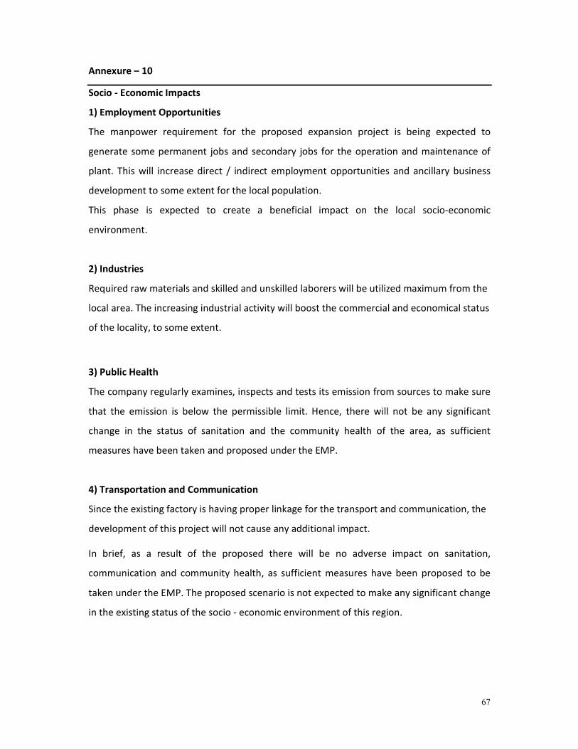
67
Annexure – 10
Socio - Economic Impacts
1) Employment Opportunities
The manpower requirement for the proposed expansion project is being expected to
generate some permanent jobs and secondary jobs for the operation and maintenance of
plant. This will increase direct / indirect employment opportunities and ancillary business
development to some extent for the local population.
This phase is expected to create a beneficial impact on the local socio-economic
environment.
2) Industries
Required raw materials and skilled and unskilled laborers will be utilized maximum from the
local area. The increasing industrial activity will boost the commercial and economical status
of the locality, to some extent.
3) Public Health
The company regularly examines, inspects and tests its emission from sources to make sure
that the emission is below the permissible limit. Hence, there will not be any significant
change in the status of sanitation and the community health of the area, as sufficient
measures have been taken and proposed under the EMP.
4) Transportation and Communication
Since the existing factory is having proper linkage for the transport and communication, the
development of this project will not cause any additional impact.
In brief, as a result of the proposed there will be no adverse impact on sanitation,
communication and community health, as sufficient measures have been proposed to be
taken under the EMP. The proposed scenario is not expected to make any significant change
in the existing status of the socio - economic environment of this region.
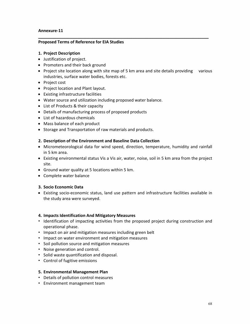
68
Annexure-11
__________________________________________________________________________
Proposed Terms of Reference for EIA Studies
1. Project Description
• Justification of project.
• Promoters and their back ground
• Project site location along with site map of 5 km area and site details providing various
industries, surface water bodies, forests etc.
• Project cost
• Project location and Plant layout.
• Existing infrastructure facilities
• Water source and utilization including proposed water balance.
• List of Products & their capacity
• Details of manufacturing process of proposed products
• List of hazardous chemicals
• Mass balance of each product
• Storage and Transportation of raw materials and products.
2. Description of the Environment and Baseline Data Collection
• Micrometeorological data for wind speed, direction, temperature, humidity and rainfall
in 5 km area.
• Existing environmental status Vis a Vis air, water, noise, soil in 5 km area from the project
site.
• Ground water quality at 5 locations within 5 km.
• Complete water balance
3. Socio Economic Data
• Existing socio-economic status, land use pattern and infrastructure facilities available in
the study area were surveyed.
4. Impacts Identification And Mitigatory Measures
• Identification of impacting activities from the proposed project during construction and
operational phase.
• Impact on air and mitigation measures including green belt
• Impact on water environment and mitigation measures
• Soil pollution source and mitigation measures
• Noise generation and control.
• Solid waste quantification and disposal.
• Control of fugitive emissions
5. Environmental Management Plan
• Details of pollution control measures
• Environment management team
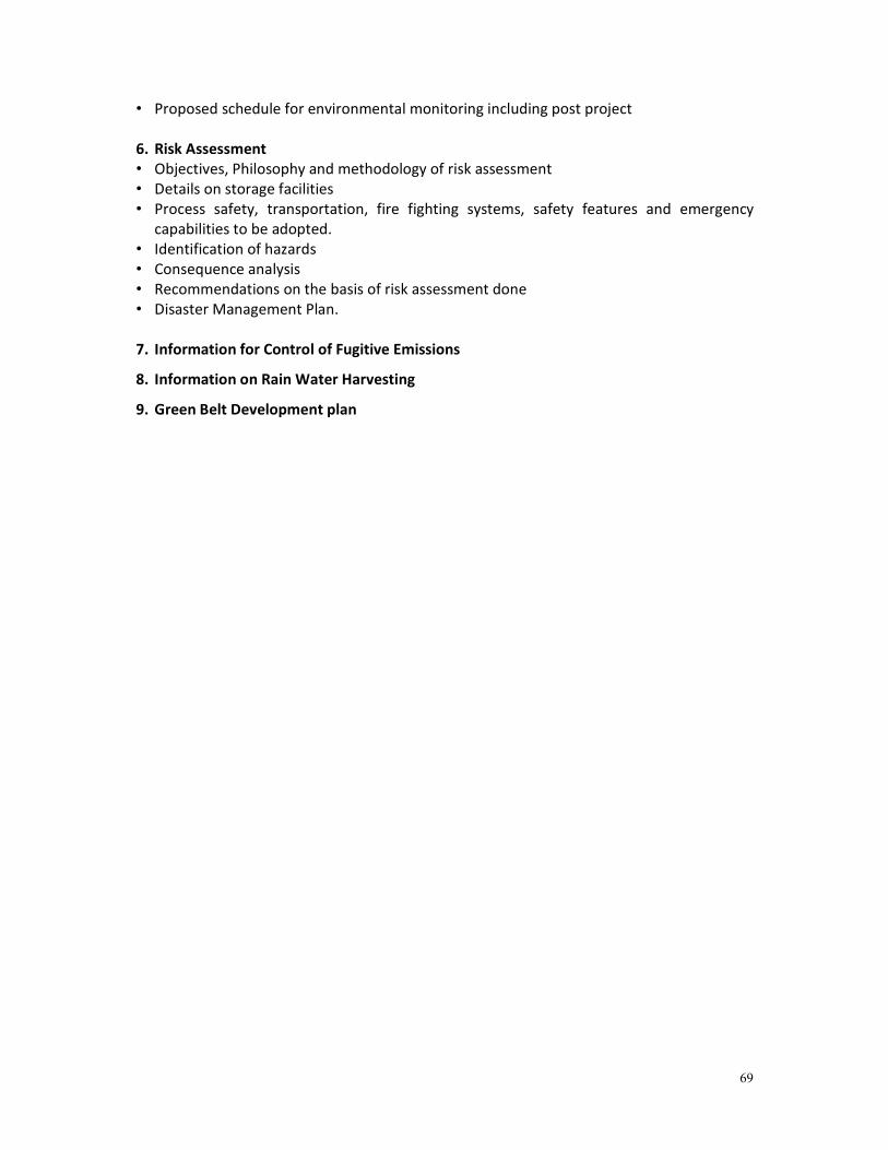
69
• Proposed schedule for environmental monitoring including post project
6. Risk Assessment
• Objectives, Philosophy and methodology of risk assessment
• Details on storage facilities
• Process safety, transportation, fire fighting systems, safety features and emergency
capabilities to be adopted.
• Identification of hazards
• Consequence analysis
• Recommendations on the basis of risk assessment done
• Disaster Management Plan.
7. Information for Control of Fugitive Emissions
8. Information on Rain Water Harvesting
9. Green Belt Development plan