Embed Size (px)
Citation preview
Propulsion and Steering ofan Autonomous Sailboat
Mert Urkmez (3 Credits) / Class of 2017 / MechanicalEngineer / mu63
Gabriel Zimmerman (4 Credits) / Class of 2017 /Mechanical Engineer / giz4
5/13/2016
Contents
1 Abstract 3
2 Introduction 3
3 Sail and Tail Design 33.1 Dimensions . . . . . . . . . . . . . . . . . . . . . . . . . . . . . . 33.2 Airfoil Selection and Analysis . . . . . . . . . . . . . . . . . . . . 43.3 Sail and Tail Design Rationale . . . . . . . . . . . . . . . . . . . 63.4 Sail and Tail Manufacturing . . . . . . . . . . . . . . . . . . . . . 7
4 Sail and Tail Tests 134.1 Actuation Test . . . . . . . . . . . . . . . . . . . . . . . . . . . . 134.2 Actuation Test After Modification . . . . . . . . . . . . . . . . . 134.3 Cayuga Lake Testing . . . . . . . . . . . . . . . . . . . . . . . . . 14
5 Lessons From First Prototype 14
6 Future Design Work 15
7 Conclusion 16
8 Appendices 168.1 Importing Airfoil Into CAD . . . . . . . . . . . . . . . . . . . . . 168.2 Joining Carbon Fiber Tubes . . . . . . . . . . . . . . . . . . . . . 178.3 Using Design Spreadsheet to Analyze Main Sail Axle . . . . . . . 178.4 Sail and Tail Parts List . . . . . . . . . . . . . . . . . . . . . . . 19
2
1 Abstract
This semester our goal was to build an autonomous sailboat that could suc-cessfully navigate GPS waypoints placed on Cayuga Lake in Ithaca New York.Based on previous semesters’research, a directionally stable sailboat design in-volves both a rigid airfoil sail and tail. The airfoil tail acts as an air rudder andremoves the need for a water rudder[2]. We aimed to increase durability whiledecreasing the overall weight of the sail and tail by using design and manufac-turing techniques inspired by plane wings built by the Design Build Fly (DBF)project team. The sail and tail assembly met the set expectations. The prede-termined weight limit of 750 grams, according to the mass budget calculations,was achieved with our completed sail and tail assembly weighing 700 grams.The sail was able to withstand the forces from wind up to 50 mph according toa 2-dimensional ANSYS finite element analysis discussed in detail below. Fi-nally, and most importantly, the sail and tail assembly was able to propel andsteer the entire sailboat on Cayuga Lake.
2 Introduction
Each control surface, the sail for propulsion and the tail for steering, is containedin one larger assembly. Jesse Miller, a mechanical engineering student at CornellUniversity, created a MatLab simulation with an optimizing function whichiterated through boat parameters including sail, tail, and keel dimensions tomaximize the boat’s velocity-made-good[1]. The sail and tail dimensions wereoptimized for 5 m/s winds. This sail is referred to as the low-wind-sail, gearedtowards generating maximum lift in low wind conditions. In harsher sailingenvironments, a high-wind-sail which is shorter in length should be used toreduce the total lift generated and therefore reduce the high stresses on thesail assembly. Generating less lift is also important in maintaining the boat’sdirectional stability[1]. To dimension this high-wind-sail, the simulation andoptimizing function should be run with the desired wind speed.
3 Sail and Tail Design
3.1 Dimensions
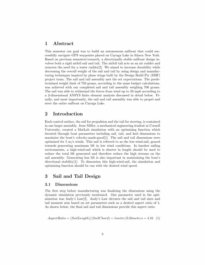
The first step before manufacturing was finalizing the dimensions using thedynamic simulation previously mentioned. One parameter used in the opti-mization was Andy’s Law[2]. Andy’s Law dictates the sail and tail sizes andtail moment arm based on set parameters such as a desired aspect ratio of 4.As shown below, the final sail and tail dimensions provide this aspect ratio.
AspectRatio = (SailLength)/(SailChord) = 1meter/0.24meters = 4.16 (1)
3
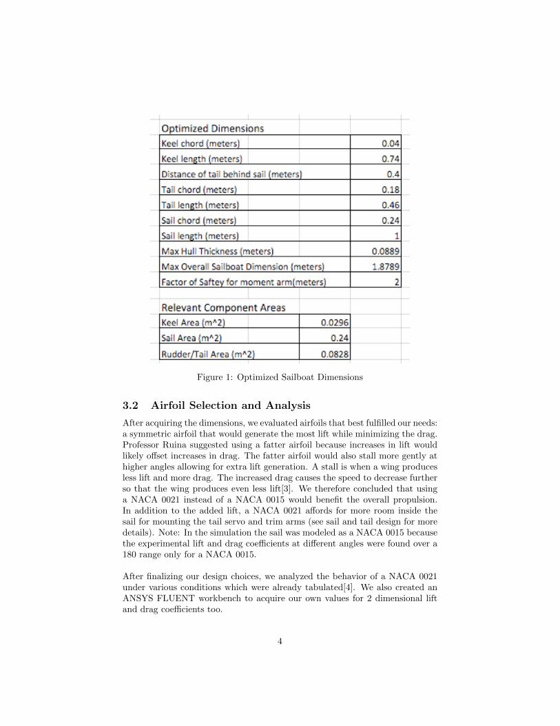
Figure 1: Optimized Sailboat Dimensions
3.2 Airfoil Selection and Analysis
After acquiring the dimensions, we evaluated airfoils that best fulfilled our needs:a symmetric airfoil that would generate the most lift while minimizing the drag.Professor Ruina suggested using a fatter airfoil because increases in lift wouldlikely offset increases in drag. The fatter airfoil would also stall more gently athigher angles allowing for extra lift generation. A stall is when a wing producesless lift and more drag. The increased drag causes the speed to decrease furtherso that the wing produces even less lift[3]. We therefore concluded that usinga NACA 0021 instead of a NACA 0015 would benefit the overall propulsion.In addition to the added lift, a NACA 0021 affords for more room inside thesail for mounting the tail servo and trim arms (see sail and tail design for moredetails). Note: In the simulation the sail was modeled as a NACA 0015 becausethe experimental lift and drag coefficients at different angles were found over a180 range only for a NACA 0015.
After finalizing our design choices, we analyzed the behavior of a NACA 0021under various conditions which were already tabulated[4]. We also created anANSYS FLUENT workbench to acquire our own values for 2 dimensional liftand drag coefficients too.
4
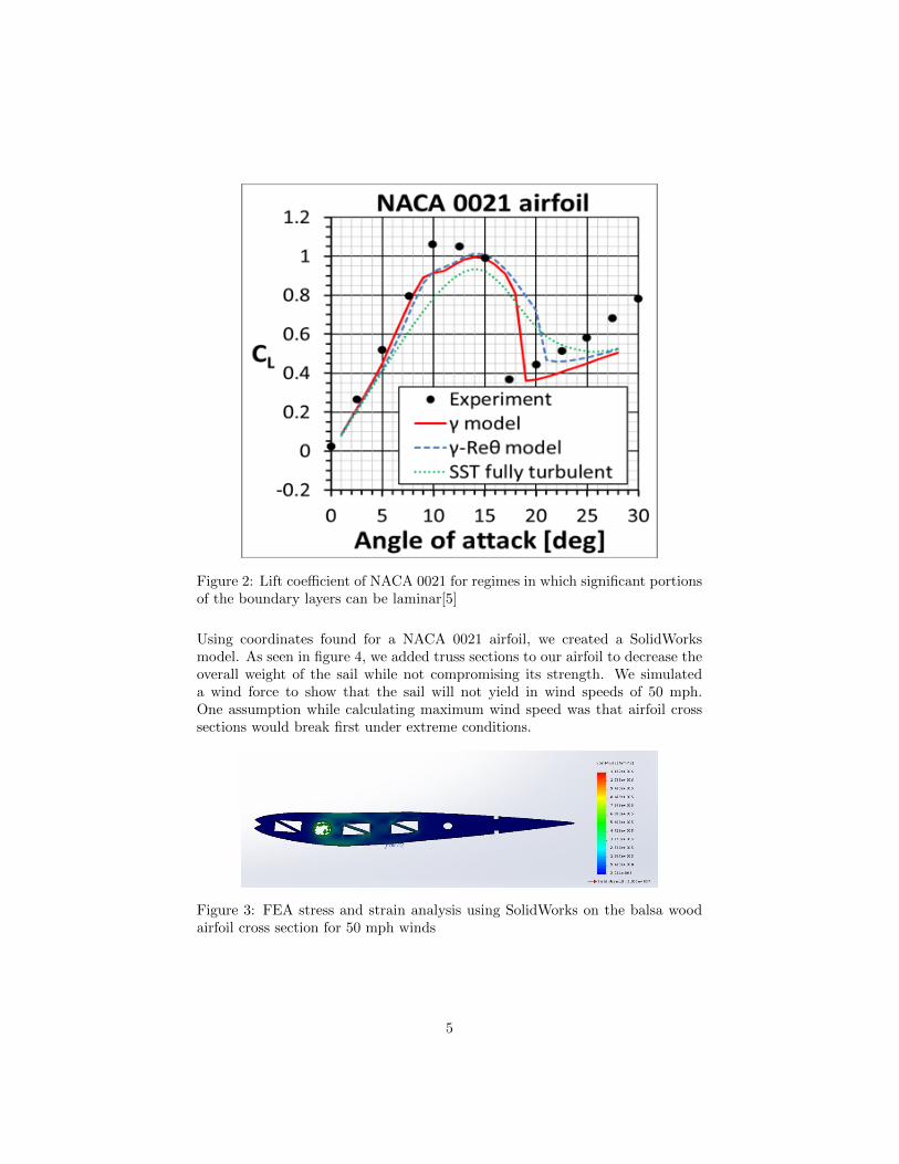
Figure 2: Lift coefficient of NACA 0021 for regimes in which significant portionsof the boundary layers can be laminar[5]
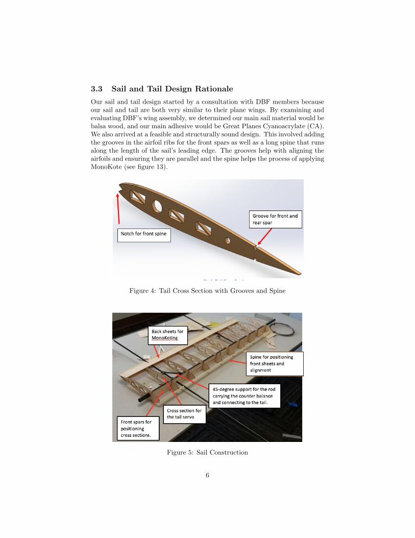
Using coordinates found for a NACA 0021 airfoil, we created a SolidWorksmodel. As seen in figure 4, we added truss sections to our airfoil to decrease theoverall weight of the sail while not compromising its strength. We simulateda wind force to show that the sail will not yield in wind speeds of 50 mph.One assumption while calculating maximum wind speed was that airfoil crosssections would break first under extreme conditions.
Figure 3: FEA stress and strain analysis using SolidWorks on the balsa woodairfoil cross section for 50 mph winds
5
3.3 Sail and Tail Design Rationale
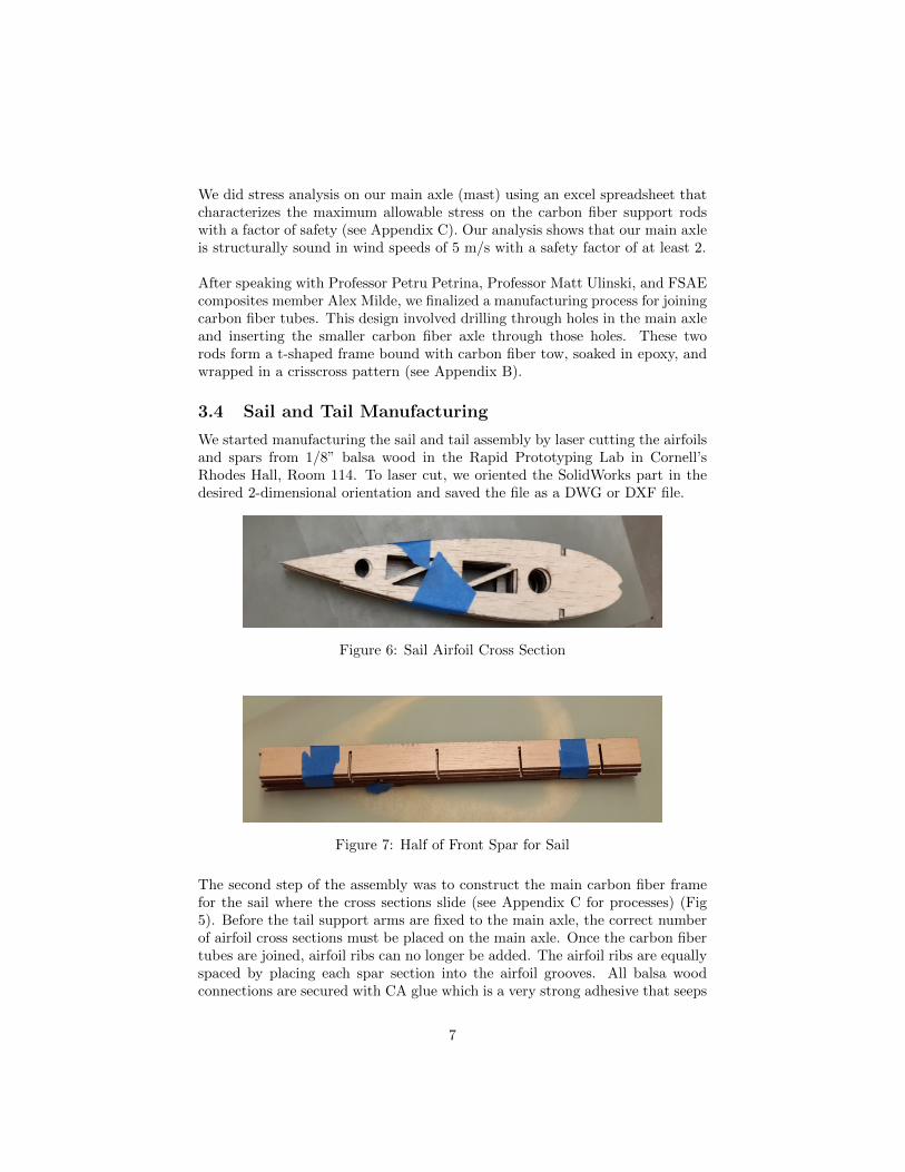
Our sail and tail design started by a consultation with DBF members becauseour sail and tail are both very similar to their plane wings. By examining andevaluating DBF’s wing assembly, we determined our main sail material would bebalsa wood, and our main adhesive would be Great Planes Cyanoacrylate (CA).We also arrived at a feasible and structurally sound design. This involved addingthe grooves in the airfoil ribs for the front spars as well as a long spine that runsalong the length of the sail’s leading edge. The grooves help with aligning theairfoils and ensuring they are parallel and the spine helps the process of applyingMonoKote (see figure 13).
Figure 4: Tail Cross Section with Grooves and Spine
Figure 5: Sail Construction
6
We did stress analysis on our main axle (mast) using an excel spreadsheet thatcharacterizes the maximum allowable stress on the carbon fiber support rodswith a factor of safety (see Appendix C). Our analysis shows that our main axleis structurally sound in wind speeds of 5 m/s with a safety factor of at least 2.
After speaking with Professor Petru Petrina, Professor Matt Ulinski, and FSAEcomposites member Alex Milde, we finalized a manufacturing process for joiningcarbon fiber tubes. This design involved drilling through holes in the main axleand inserting the smaller carbon fiber axle through those holes. These tworods form a t-shaped frame bound with carbon fiber tow, soaked in epoxy, andwrapped in a crisscross pattern (see Appendix B).
3.4 Sail and Tail Manufacturing
We started manufacturing the sail and tail assembly by laser cutting the airfoilsand spars from 1/8” balsa wood in the Rapid Prototyping Lab in Cornell’sRhodes Hall, Room 114. To laser cut, we oriented the SolidWorks part in thedesired 2-dimensional orientation and saved the file as a DWG or DXF file.
Figure 6: Sail Airfoil Cross Section
Figure 7: Half of Front Spar for Sail
The second step of the assembly was to construct the main carbon fiber framefor the sail where the cross sections slide (see Appendix C for processes) (Fig5). Before the tail support arms are fixed to the main axle, the correct numberof airfoil cross sections must be placed on the main axle. Once the carbon fibertubes are joined, airfoil ribs can no longer be added. The airfoil ribs are equallyspaced by placing each spar section into the airfoil grooves. All balsa woodconnections are secured with CA glue which is a very strong adhesive that seeps
7
into the wood. Only a small drop or two is needed for a secure connection. Thisbalsa wood cross section and spar assembly is then fixed to the carbon fiber axleusing the same CA glue.
Following the placement of cross sections, we glued 1/16” balsa wood sheetson the front and back of the airfoils which provided support for the MonoKote(front sheets not shown in Fig 5). Without these sheets, the MonoKote is proneto bow in between contact points.
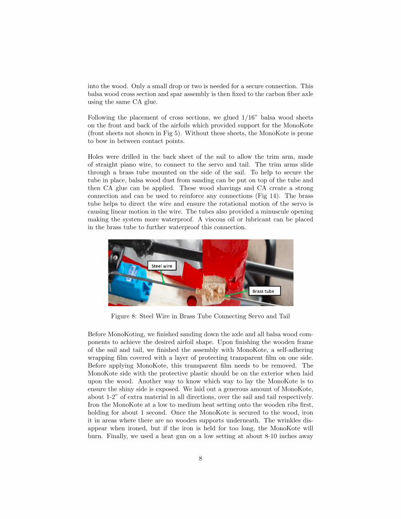
Holes were drilled in the back sheet of the sail to allow the trim arm, madeof straight piano wire, to connect to the servo and tail. The trim arms slidethrough a brass tube mounted on the side of the sail. To help to secure thetube in place, balsa wood dust from sanding can be put on top of the tube andthen CA glue can be applied. These wood shavings and CA create a strongconnection and can be used to reinforce any connections (Fig 14). The brasstube helps to direct the wire and ensure the rotational motion of the servo iscausing linear motion in the wire. The tubes also provided a minuscule openingmaking the system more waterproof. A viscous oil or lubricant can be placedin the brass tube to further waterproof this connection.
Figure 8: Steel Wire in Brass Tube Connecting Servo and Tail
Before MonoKoting, we finished sanding down the axle and all balsa wood com-ponents to achieve the desired airfoil shape. Upon finishing the wooden frameof the sail and tail, we finished the assembly with MonoKote, a self-adheringwrapping film covered with a layer of protecting transparent film on one side.Before applying MonoKote, this transparent film needs to be removed. TheMonoKote side with the protective plastic should be on the exterior when laidupon the wood. Another way to know which way to lay the MonoKote is toensure the shiny side is exposed. We laid out a generous amount of MonoKote,about 1-2” of extra material in all directions, over the sail and tail respectively.Iron the MonoKote at a low to medium heat setting onto the wooden ribs first,holding for about 1 second. Once the MonoKote is secured to the wood, ironit in areas where there are no wooden supports underneath. The wrinkles dis-appear when ironed, but if the iron is held for too long, the MonoKote willburn. Finally, we used a heat gun on a low setting at about 8-10 inches away
8
to remove the final wrinkles from the MonoKote film. It should be taut aroundthe entire assembly. It is important that the MonoKote fully wraps around thewing structure because this closed loop is a major source of torsional strength.
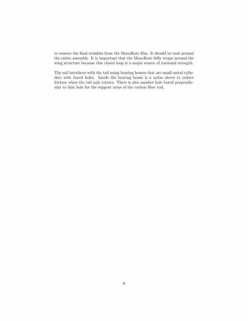
The sail interfaces with the tail using bearing houses that are small metal cylin-ders with bored holes. Inside the bearing house is a nylon sleeve to reducefriction when the tail axle rotates. There is also another hole bored perpendic-ular to that hole for the support arms of the carbon fiber rod.
9
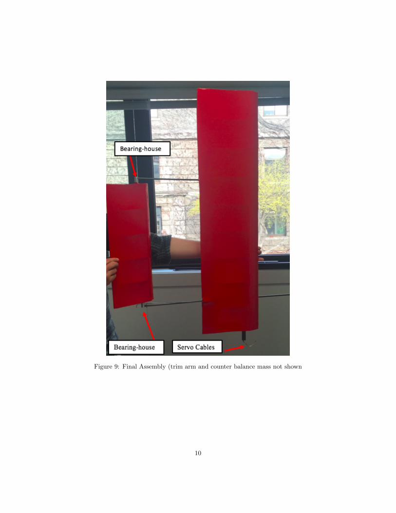
Figure 9: Final Assembly (trim arm and counter balance mass not shown
10
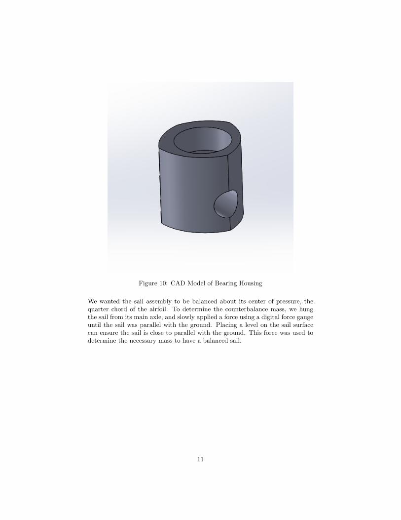
Figure 10: CAD Model of Bearing Housing
We wanted the sail assembly to be balanced about its center of pressure, thequarter chord of the airfoil. To determine the counterbalance mass, we hungthe sail from its main axle, and slowly applied a force using a digital force gaugeuntil the sail was parallel with the ground. Placing a level on the sail surfacecan ensure the sail is close to parallel with the ground. This force was used todetermine the necessary mass to have a balanced sail.
11
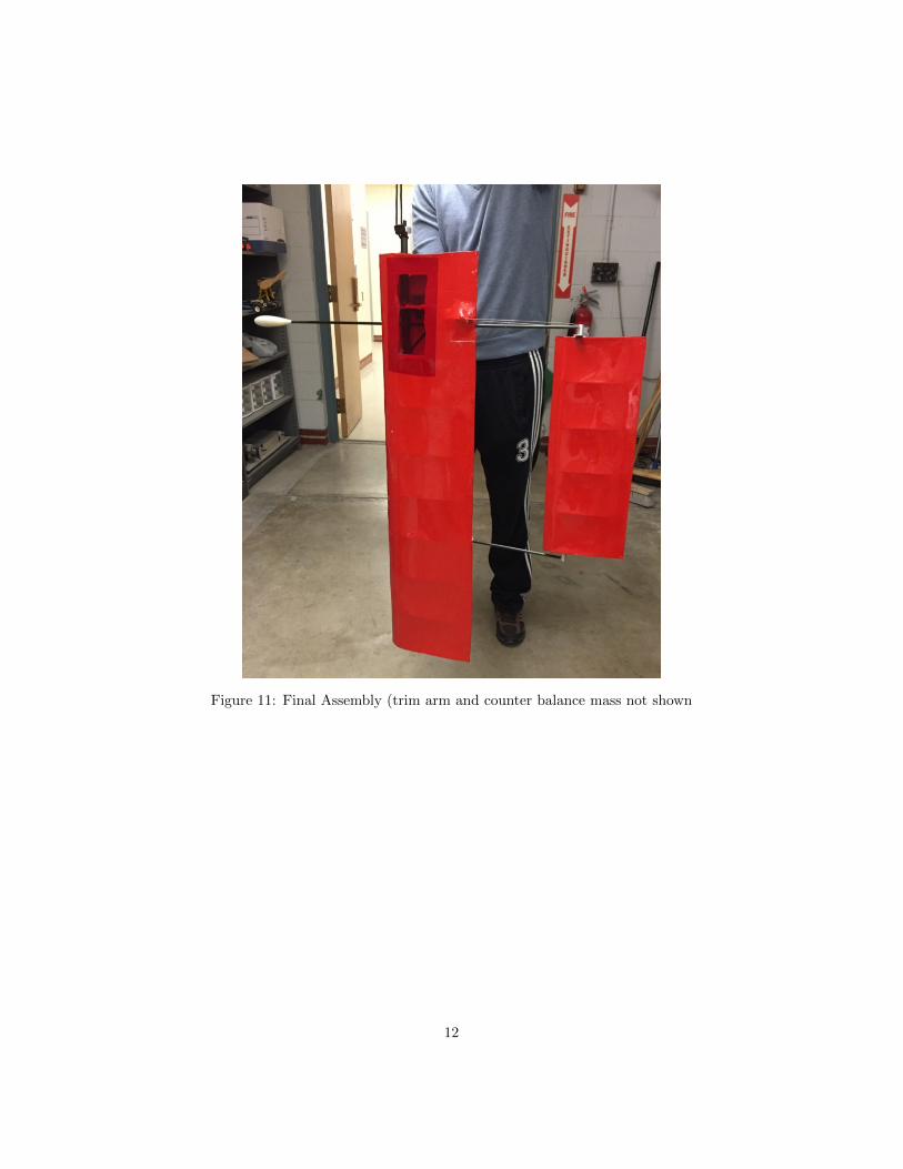
Figure 11: Final Assembly (trim arm and counter balance mass not shown
12
4 Sail and Tail Tests
Upon finishing our assembly, we did a series of tests on Cayuga Lake and inProfessor Ruina’s Lab to check the actuation of our assembly and determineany necessary modifications.
4.1 Actuation Test
We conducted a tail trimming test using the full sail and tail assembly withArjan Singh, a member of the navigation team. The first challenge in our actu-ation test was determining the servo’s zero position. When installing the servo,we did not run an electronics command to center the servo. Therefore, when thetail was sitting at an angle of zero with respect to the sail, the servo’s positionwas not exactly zero. In the future, zeroing the servo before securing it insidethe sail would help the interface with the electronics and navigation. Once theservo was centered, we experimented with the angular range of movement oneither side of the neutral axis. (There is a known stall angle of 30◦ to either sideof the neutral axis according to the dynamics simulation.) These tests allowedus to determine both whether the stiff piano wires would transmit the servotorque and also whether the desired range of angles was achievable.
The results can be found in the ”Test Videos” folder in the ”Sailboat Spring2016” folder. The overall result of the testing was very positive. We were ableto successfully trim the tail using the PCB. One potential issue was the trimwire interfering with the front of the tail at larger angles.
4.2 Actuation Test After Modification
After the initial test, we decided to fix the trim arms controlling the tail as theywere only allowing rotations of less than 15 degrees in both directions. We cutopen the section of the sail containing the tail servo to replace the wires andbrass tubes in a new formation which would allow for unhindered rotation.
13
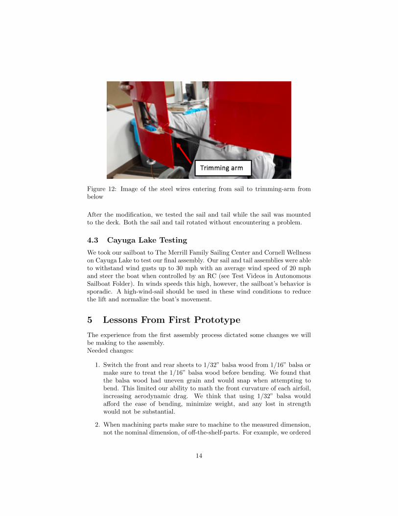
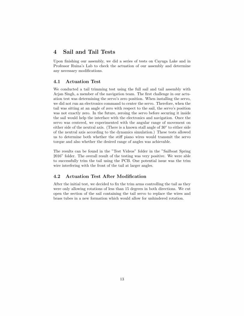
Figure 12: Image of the steel wires entering from sail to trimming-arm frombelow
After the modification, we tested the sail and tail while the sail was mountedto the deck. Both the sail and tail rotated without encountering a problem.
4.3 Cayuga Lake Testing
We took our sailboat to The Merrill Family Sailing Center and Cornell Wellnesson Cayuga Lake to test our final assembly. Our sail and tail assemblies were ableto withstand wind gusts up to 30 mph with an average wind speed of 20 mphand steer the boat when controlled by an RC (see Test Videos in AutonomousSailboat Folder). In winds speeds this high, however, the sailboat’s behavior issporadic. A high-wind-sail should be used in these wind conditions to reducethe lift and normalize the boat’s movement.
5 Lessons From First Prototype
The experience from the first assembly process dictated some changes we willbe making to the assembly.Needed changes:
1. Switch the front and rear sheets to 1/32” balsa wood from 1/16” balsa ormake sure to treat the 1/16” balsa wood before bending. We found thatthe balsa wood had uneven grain and would snap when attempting tobend. This limited our ability to math the front curvature of each airfoil,increasing aerodynamic drag. We think that using 1/32” balsa wouldafford the ease of bending, minimize weight, and any lost in strengthwould not be substantial.
2. When machining parts make sure to machine to the measured dimension,not the nominal dimension, of off-the-shelf-parts. For example, we ordered
14
two identical nylon sleeve bearings and each had a different outer diameter.Therefore, even though we machined both parts identically, they both didnot work because of tolerances. This is a lesson to be applied to allmachined parts on the boat.
3. When aligning spars, use purchased machining blocks to ensure 90◦ anglesbetween each airfoil and the spar. Because the machining blocks have nearperfect perpendicular faces, they can easily be used to help alignment.
6 Future Design Work
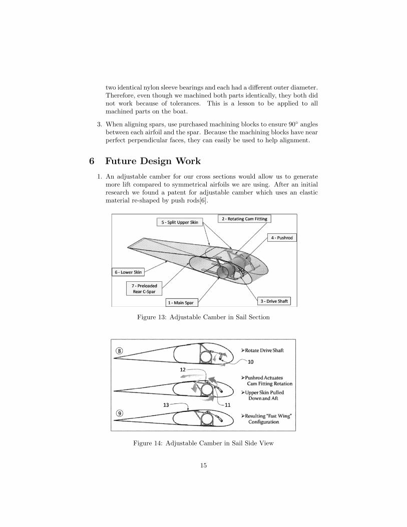
1. An adjustable camber for our cross sections would allow us to generatemore lift compared to symmetrical airfoils we are using. After an initialresearch we found a patent for adjustable camber which uses an elasticmaterial re-shaped by push rods[6].
Figure 13: Adjustable Camber in Sail Section
Figure 14: Adjustable Camber in Sail Side View
15
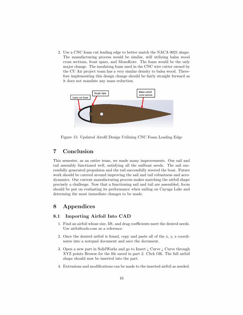
2. Use a CNC foam cut leading edge to better match the NACA 0021 shape.The manufacturing process would be similar, still utilizing balsa woodcross sections, front spars, and MonoKote. The foam would be the onlymajor change. The insulating foam used in the CNC wire cutter owned bythe CU Air project team has a very similar density to balsa wood. There-fore implementing this design change should be fairly straight forward asit does not mandate any mass reduction.
Figure 15: Updated Airofil Design Utilizing CNC Foam Leading Edge
7 Conclusion
This semester, as an entire team, we made many improvements. Our sail andtail assembly functioned well, satisfying all the sailboat needs. The sail suc-cessfully generated propulsion and the tail successfully steered the boat. Futurework should be catered around improving the sail and tail robustness and aero-dynamics. Our current manufacturing process makes matching the airfoil shapeprecisely a challenge. Now that a functioning sail and tail are assembled, focusshould be put on evaluating its performance when sailing on Cayuga Lake anddeterming the most immediate changes to be made.
8 Appendices
8.1 Importing Airfoil Into CAD
1. Find an airfoil whose size, lift, and drag coefficients meet the desired needs.Use airfoiltools.com as a reference.
2. Once the desired airfoil is found, copy and paste all of the x, y, z coordi-nates into a notepad document and save the document.
3. Open a new part in SolidWorks and go to Insert ¿ Curve ¿ Curve throughXYZ points Browse for the file saved in part 2. Click OK. The full airfoilshape should now be inserted into the part.
4. Extrusions and modifications can be made to the inserted airfoil as needed.
16
8.2 Joining Carbon Fiber Tubes
1. A through hole matching the outer diameter of the smaller tube is drilledinto the tube with bigger diameter. Use a fixture or rig to keep the tubestill. Both holes must be drilled completely perpendicular and in the sameplane. Using a fixture will ensure the hole placements are correct.
2. The smaller tube is placed through the drilled hole. The smaller tube canstick out from the hole 0.5-1” if space permits in the general assembly.
3. Cut enough carbon fiber tow to wrap around the tubes at least 3 times.In our assembly, this was approximately 18”, but the length needed willvary with tube diameters. Both ends are tied to prevent unraveling. Oneend is glued near the hole drilled on carbon fiber tube.
4. Paint epoxy onto the carbon fiber tow using a brush.
5. Wrap the carbon fiber tow around the tubes in a crisscross pattern.
6. Secure the loose end of the epoxy tow using a rubber band or a knottedthread to ensure the tow remains tightly bound around the joint.
8.3 Using Design Spreadsheet to Analyze Main Sail Axle
1. This design sheet is not a substitute for hand calculations and other formsof analysis. Its purpose is to give a preliminary design analysis. It canhelp determine a factor of safety before moving forth with manufacturing.Make sure additional analysis confirms design spreadsheet implications.
2. Load the ”Sail Tail Design Sheet.xlxs” found in the Autonomous SailboatGoogle Drive: Propulsion Block: Measurements and Calculations:. Thepurpose of this design sheet is to analyze the stresses on the main carbonfiber axle. Varying inputs and dimensions allow a general understandingof the structural integrity of the sail frame.
3. Be sure to read the Assumptions Tab. It outlines the simplifications madein the problem and explains how the forces and loads are applied. Theimage below shows the sail and tail assembly. Each of the two point loadscontributing to the total stress state are shown.
17
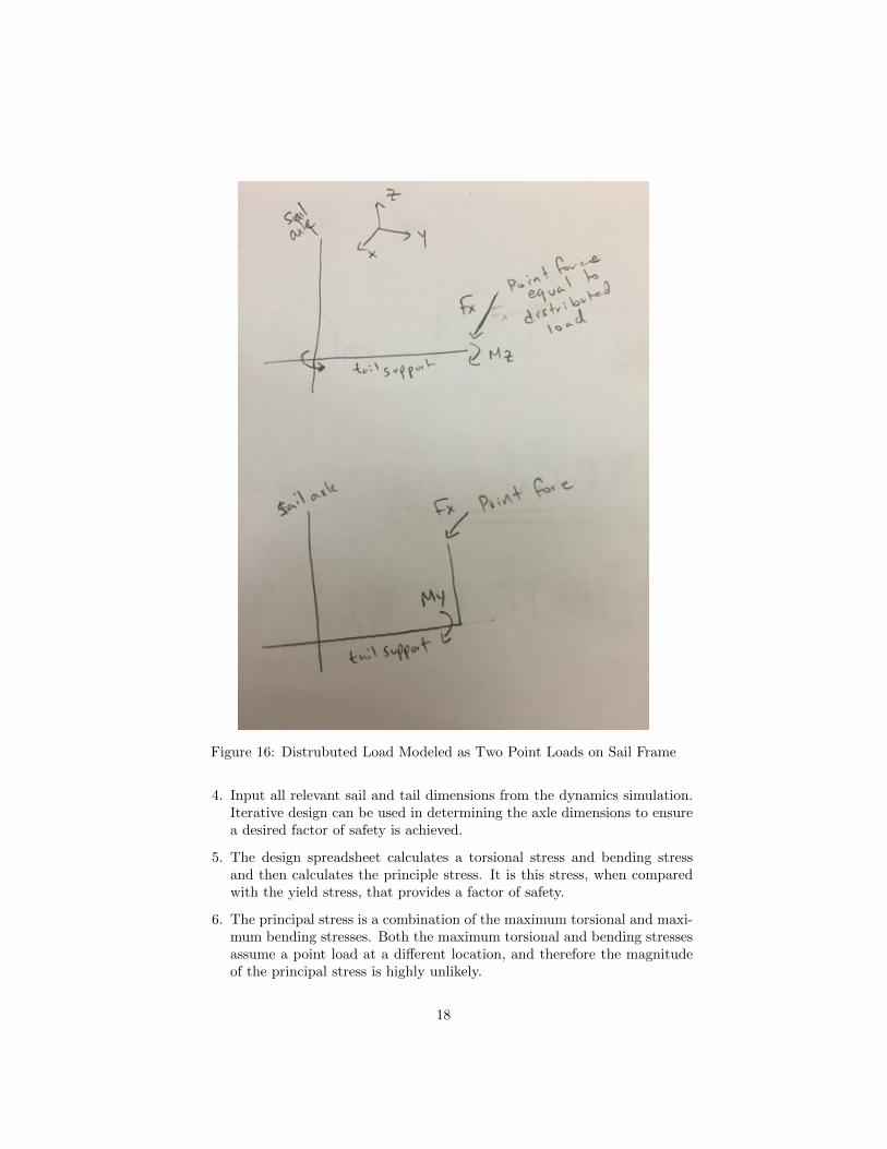
Figure 16: Distrubuted Load Modeled as Two Point Loads on Sail Frame
4. Input all relevant sail and tail dimensions from the dynamics simulation.Iterative design can be used in determining the axle dimensions to ensurea desired factor of safety is achieved.
5. The design spreadsheet calculates a torsional stress and bending stressand then calculates the principle stress. It is this stress, when comparedwith the yield stress, that provides a factor of safety.
6. The principal stress is a combination of the maximum torsional and maxi-mum bending stresses. Both the maximum torsional and bending stressesassume a point load at a different location, and therefore the magnitudeof the principal stress is highly unlikely.
18
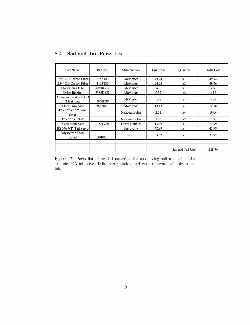
8.4 Sail and Tail Parts List
Figure 17: Parts list of needed materials for assembling sail and tail. Listexcludes CA adhesive, drills, razor blades, and various items available in thelab.
19
References
[1] Miller, J. Direcitonally Stable Robotic Sailing. Cornell University. (2016)
[2] Augenstein, T. Cornell Autonmous Sailboat Team Fall 2015 Report. CornellUniversity (2015)
[3] Shih, C., Lourenco, L., Van Dommelen, L. & Krothapalli, A. (1992) Un-steady flow past an airfoil pitching at a constant rate. AIAA Journal 301153-1161.
[4] NACA 0021 (naca0021-il) http://airfoiltools.com/airfoil/details?airfoil=naca0021-il
[5] Menter,F.(2015) Taking Laminar-Turbulent Transition Modeling to the NextLevel,ansys-blog
[6] Patent No: US20120104181 A1
20