Embed Size (px)
Citation preview
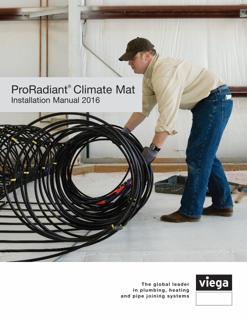
The g loba l leaderin p lumbing, heat ing
and p ipe jo in ing systems
ProRadiant® Climate Mat Installation Manual 2016
IM-PR 1017 (Climate Mat)2
Contents
1 Overview 1.1 Advantages and Benefits . . . . . . . . . . . . . . . . . . . . . . . . . . . . . . . . . . . . . . . . . . . . . . . . . . . . . . . .3 1.2 Applications . . . . . . . . . . . . . . . . . . . . . . . . . . . . . . . . . . . . . . . . . . . . . . . . . . . . . . . . . . . . . . . . . . .3 1.3 Components . . . . . . . . . . . . . . . . . . . . . . . . . . . . . . . . . . . . . . . . . . . . . . . . . . . . . . . . . . . . . . . . . .4
2 System Design 2.1 Viega's Design Services . . . . . . . . . . . . . . . . . . . . . . . . . . . . . . . . . . . . . . . . . . . . . . . . . . . . . . . . .5 2.2 Insulation . . . . . . . . . . . . . . . . . . . . . . . . . . . . . . . . . . . . . . . . . . . . . . . . . . . . . . . . . . . . . . . . . . . . 5 2.3 Floor Covering . . . . . . . . . . . . . . . . . . . . . . . . . . . . . . . . . . . . . . . . . . . . . . . . . . . . . . . . . . . . . . . .6 2.4 Controls and Equipment . . . . . . . . . . . . . . . . . . . . . . . . . . . . . . . . . . . . . . . . . . . . . . . . . . . . . . . .6 2.4.1 Heating Considerations . . . . . . . . . . . . . . . . . . . . . . . . . . . . . . . . . . . . . . . . . . . . . . . . . . . . . .6 2.4.2 Cooling Considerations . . . . . . . . . . . . . . . . . . . . . . . . . . . . . . . . . . . . . . . . . . . . . . . . . . . . . .7 2.4.3 Combination Heating and Cooling Considerations . . . . . . . . . . . . . . . . . . . . . . . . . . . . . . . .7
3 Planning the Installation 3.1 Planning . . . . . . . . . . . . . . . . . . . . . . . . . . . . . . . . . . . . . . . . . . . . . . . . . . . . . . . . . . . . . . . . . . . . . .8 3.2 Preparing the Site . . . . . . . . . . . . . . . . . . . . . . . . . . . . . . . . . . . . . . . . . . . . . . . . . . . . . . . . . . . . . .8 3.3 Off-loading and Storing the Mats . . . . . . . . . . . . . . . . . . . . . . . . . . . . . . . . . . . . . . . . . . . . . . . . 8 3.4 Layout and Staging . . . . . . . . . . . . . . . . . . . . . . . . . . . . . . . . . . . . . . . . . . . . . . . . . . . . . . . . . . . . .9
4 Installing the Climate Mat 4.1 Precautions During Installation . . . . . . . . . . . . . . . . . . . . . . . . . . . . . . . . . . . . . . . . . . . . . . . . . . .10 4.2 Repairing Tubing . . . . . . . . . . . . . . . . . . . . . . . . . . . . . . . . . . . . . . . . . . . . . . . . . . . . . . . . . . . . . 10 4.3 Fastening the Climate Mat . . . . . . . . . . . . . . . . . . . . . . . . . . . . . . . . . . . . . . . . . . . . . . . . . . . . . .10 4.3.1 Fastening to a compacted sub-base . . . . . . . . . . . . . . . . . . . . . . . . . . . . . . . . . . . . . . . . . .10 4.3.2 Fastening to rebar or wire mesh . . . . . . . . . . . . . . . . . . . . . . . . . . . . . . . . . . . . . . . . . . . . . .10 4.3.3 Fastening to an existing slab . . . . . . . . . . . . . . . . . . . . . . . . . . . . . . . . . . . . . . . . . . . . . . . .11 4.3.4 Fastening to foam insulation . . . . . . . . . . . . . . . . . . . . . . . . . . . . . . . . . . . . . . . . . . . . . . . . .11 4.4 Getting Around Obstacles . . . . . . . . . . . . . . . . . . . . . . . . . . . . . . . . . . . . . . . . . . . . . . . . . . . . . 11 4.5 Sleeving Control Joints and Slab Penetrations . . . . . . . . . . . . . . . . . . . . . . . . . . . . . . . . . . . . . 11 4.6 Pouring the Concrete . . . . . . . . . . . . . . . . . . . . . . . . . . . . . . . . . . . . . . . . . . . . . . . . . . . . . . . . . .12 4.7 Connecting to Permanent Manifolds . . . . . . . . . . . . . . . . . . . . . . . . . . . . . . . . . . . . . . . . . . . . . .12 4.8 Manifold Dimensions . . . . . . . . . . . . . . . . . . . . . . . . . . . . . . . . . . . . . . . . . . . . . . . . . . . . . . . . . .12
5 System Startup 5.1 Purging Procedure . . . . . . . . . . . . . . . . . . . . . . . . . . . . . . . . . . . . . . . . . . . . . . . . . . . . . . . . . . . .14
Appendix A - Climate Mat Details . . . . . . . . . . . . . . . . . . . . . . . . . . . . . . . . . . . . . . . . . . . . . . . . . . . .15
Appendix B - ViegaPEX Barrier Tubing B.1 Materials . . . . . . . . . . . . . . . . . . . . . . . . . . . . . . . . . . . . . . . . . . . . . . . . . . . . . . . . . . . . . . . . . . . .16 B.2 Marking and Certification . . . . . . . . . . . . . . . . . . . . . . . . . . . . . . . . . . . . . . . . . . . . . . . . . . . . . . .16 B.3 Handling and Installation . . . . . . . . . . . . . . . . . . . . . . . . . . . . . . . . . . . . . . . . . . . . . . . . . . . . . . .16 B.4 Recommended Uses . . . . . . . . . . . . . . . . . . . . . . . . . . . . . . . . . . . . . . . . . . . . . . . . . . . . . . . . . .16 B.5 Quality Assurance . . . . . . . . . . . . . . . . . . . . . . . . . . . . . . . . . . . . . . . . . . . . . . . . . . . . . . . . . . . . .17
Appendix C - Pressure Drop Charts . . . . . . . . . . . . . . . . . . . . . . . . . . . . . . . . . . . . . . . . . . . . . . . . . .18
Appendix D - Mixing Device Flow Rate Table . . . . . . . . . . . . . . . . . . . . . . . . . . . . . . . . . . . . . . . . . .20
Appendix E - Floor Covering R-values . . . . . . . . . . . . . . . . . . . . . . . . . . . . . . . . . . . . . . . . . . . . . . . .21
Viega products are designed to be installed by licensed and trained plumbing and mechanical professionals who are familiar with Viega products and their installation. Installation by non-professionals may void Viega LLC’s warranty.
3IM-PR 1017 (Climate Mat)
1 Overview
1.1 Advantages and Benefits
Climate Mat was developed by Viega to deliver the well documented advantages of radiant heating and/or cooling within a package that increases affordability and labor-efficiency for mid- and large scale jobs. Unlike typical radiant tubing installations, which require that individual lengths of tubing be extended and attached to a sub-base, Climate Mat is a tubing module which permits the installer to simply roll out as many as six equivalent lengths of tubing simultaneously. Advantages over typical installations include:
• Reduced installation time • Tubing securement method guarantees desired tubing spacing • Pre-pressurized tubing eliminates downtime.• Pre-engineered design taking the guesswork out of installation• No balancing needed due to same circuit lengths
1.2 Applications
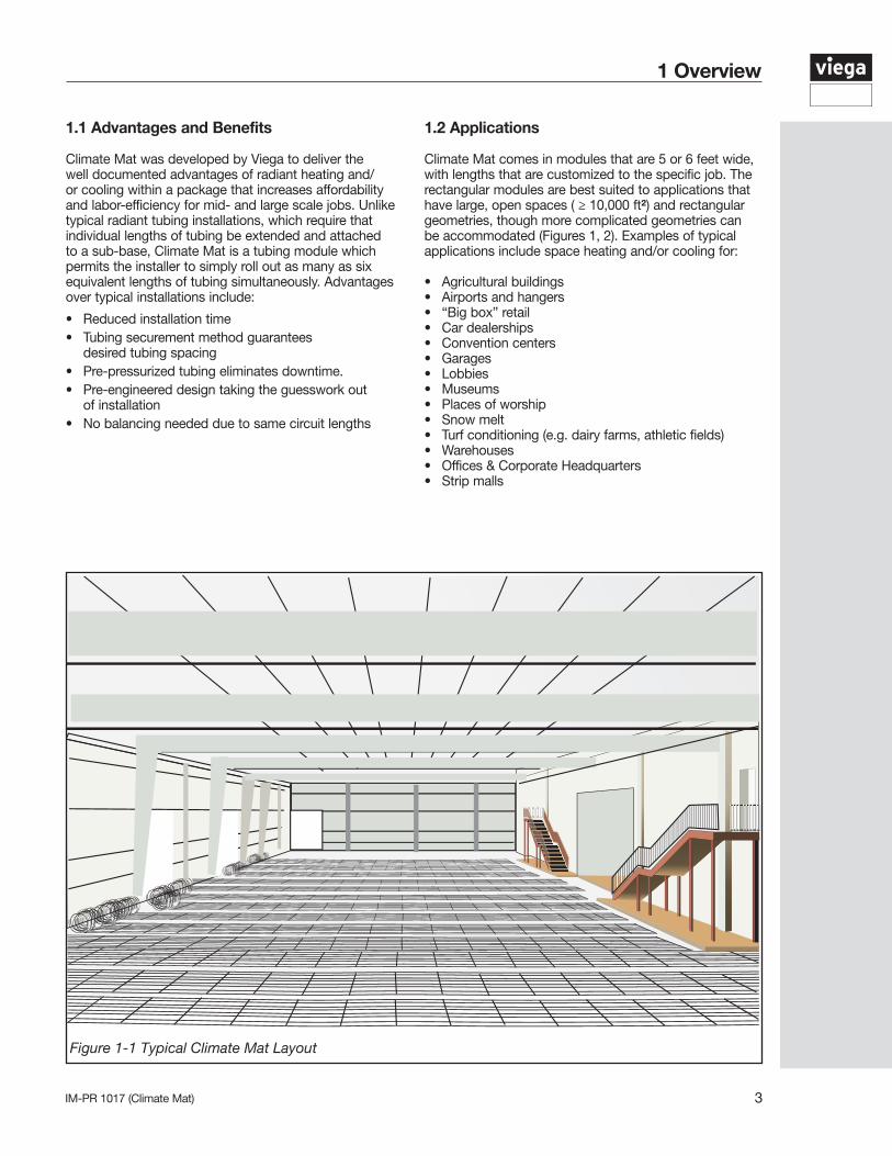
Climate Mat comes in modules that are 5 or 6 feet wide, with lengths that are customized to the specific job. The rectangular modules are best suited to applications that have large, open spaces ( ≥ 10,000 ft²) and rectangular geometries, though more complicated geometries can be accommodated (Figures 1, 2). Examples of typical applications include space heating and/or cooling for:
• Agricultural buildings• Airports and hangers• “Big box” retail• Car dealerships• Convention centers• Garages• Lobbies• Museums• Places of worship• Snow melt• Turf conditioning (e.g. dairy farms, athletic fields)• Warehouses• Offices & Corporate Headquarters• Strip malls
Figure 1-1 Typical Climate Mat Layout
IM-PR 1017 (Climate Mat)4
While Climate Mat is made to cover large areas, you can still achieve a high degree of climate control in your spaces, since each module can be individually zoned. Individual zoning of mats is not necessary in most applications, but may be desirable along perimeters in very cold climates or where there is a large amount of glazing. For example, heating capacity of the Climate Mat is typically limited to ~35 Btu/hr•ft² in areas intended for human occupancy, but this may be increased to over 50 Btu/hr•ft² along the perimeter of a building.
1.3 Components
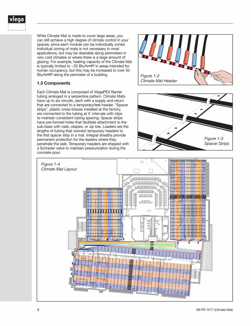
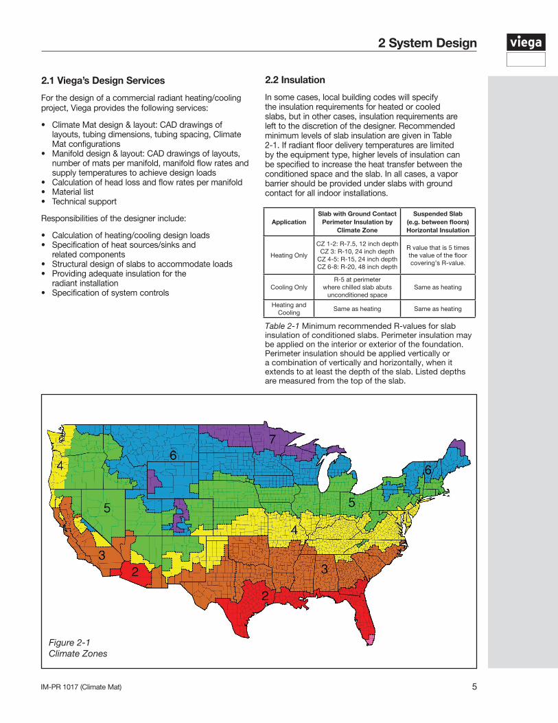
Each Climate Mat is composed of ViegaPEX Barrier tubing arranged in a serpentine pattern. Climate Mats have up to six circuits, each with a supply and return that are connected to a temporary/test header. “Spacer strips”, plastic cross-braces installed at the factory, are connected to the tubing at 4' intervals with clips to maintain consistent tubing spacing. Spacer strips have pre-formed holes that facilitate attachment to the sub-base with nails, staples, or zip ties. Leaders are the lengths of tubing that connect temporary headers to the first spacer strip in a mat. Integral sheaths provide permanent protection for the leaders where they penetrate the slab. Temporary headers are shipped with a Schrader valve to maintain pressurization during the concrete pour.
Figure 1-2 Climate Mat Header
Figure 1-3 Spacer Strips
Figure 1-4 Climate Mat Layout
5IM-PR 1017 (Climate Mat)
2 System Design
2.1 Viega’s Design Services
For the design of a commercial radiant heating/cooling project, Viega provides the following services:
• Climate Mat design & layout: CAD drawings of layouts, tubing dimensions, tubing spacing, Climate Mat configurations • Manifold design & layout: CAD drawings of layouts, number of mats per manifold, manifold flow rates and supply temperatures to achieve design loads• Calculation of head loss and flow rates per manifold• Material list• Technical support
Responsibilities of the designer include:
• Calculation of heating/cooling design loads• Specification of heat sources/sinks and related components• Structural design of slabs to accommodate loads• Providing adequate insulation for the radiant installation• Specification of system controls
ApplicationSlab with Ground Contact
Perimeter Insulation by Climate Zone
Suspended Slab (e.g. between floors) Horizontal Insulation
Heating Only
CZ 1-2: R-7.5, 12 inch depth CZ 3: R-10, 24 inch depth
CZ 4-5: R-15, 24 inch depth CZ 6-8: R-20, 48 inch depth
R value that is 5 times the value of the floor covering’s R-value.
Cooling OnlyR-5 at perimeter
where chilled slab abuts unconditioned space
Same as heating
Heating and Cooling
Same as heating Same as heating
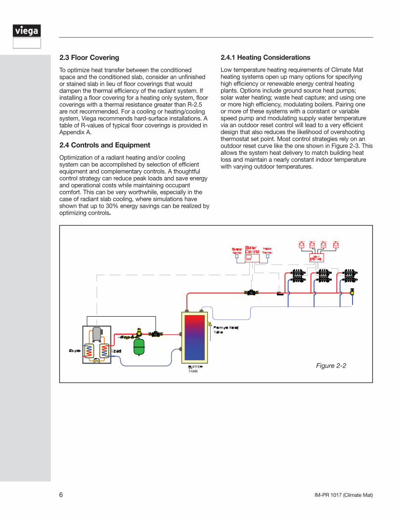
Table 2-1 Minimum recommended R-values for slab insulation of conditioned slabs. Perimeter insulation may be applied on the interior or exterior of the foundation. Perimeter insulation should be applied vertically or a combination of vertically and horizontally, when it extends to at least the depth of the slab. Listed depths are measured from the top of the slab.
2.2 Insulation
In some cases, local building codes will specify the insulation requirements for heated or cooled slabs, but in other cases, insulation requirements are left to the discretion of the designer. Recommended minimum levels of slab insulation are given in Table 2-1. If radiant floor delivery temperatures are limited by the equipment type, higher levels of insulation can be specified to increase the heat transfer between the conditioned space and the slab. In all cases, a vapor barrier should be provided under slabs with ground contact for all indoor installations.
Figure 2-1Climate Zones
IM-PR 1017 (Climate Mat)6
2.3 Floor Covering
To optimize heat transfer between the conditioned space and the conditioned slab, consider an unfinished or stained slab in lieu of floor coverings that would dampen the thermal efficiency of the radiant system. If installing a floor covering for a heating only system, floor coverings with a thermal resistance greater than R-2.5 are not recommended. For a cooling or heating/cooling system, Viega recommends hard-surface installations. A table of R-values of typical floor coverings is provided in Appendix A.
2.4 Controls and Equipment
Optimization of a radiant heating and/or cooling system can be accomplished by selection of efficient equipment and complementary controls. A thoughtful control strategy can reduce peak loads and save energy and operational costs while maintaining occupant comfort. This can be very worthwhile, especially in the case of radiant slab cooling, where simulations have shown that up to 30% energy savings can be realized by optimizing controls.
2.4.1 Heating Considerations
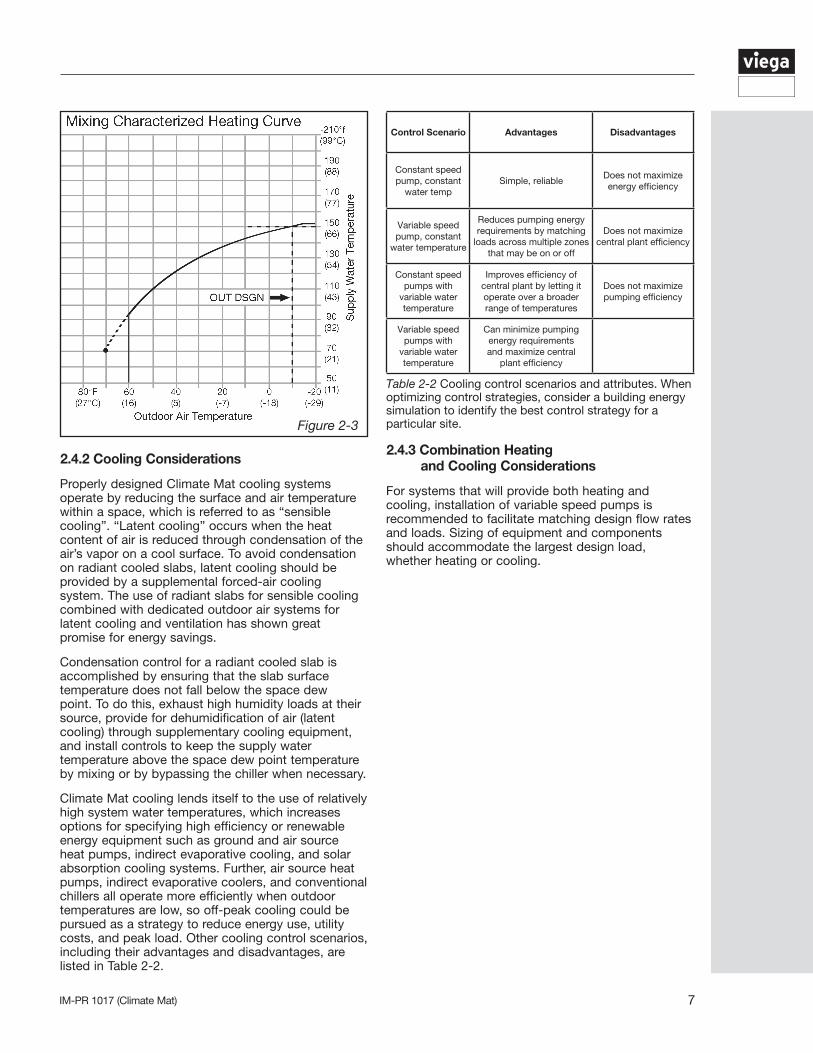
Low temperature heating requirements of Climate Mat heating systems open up many options for specifying high efficiency or renewable energy central heating plants. Options include ground source heat pumps; solar water heating; waste heat capture; and using one or more high efficiency, modulating boilers. Pairing one or more of these systems with a constant or variable speed pump and modulating supply water temperature via an outdoor reset control will lead to a very efficient design that also reduces the likelihood of overshooting thermostat set point. Most control strategies rely on an outdoor reset curve like the one shown in Figure 2-3. This allows the system heat delivery to match building heat loss and maintain a nearly constant indoor temperature with varying outdoor temperatures.
Figure 2-2
7IM-PR 1017 (Climate Mat)
Control Scenario Advantages Disadvantages
Constant speed pump, constant
water tempSimple, reliable
Does not maximize energy efficiency
Variable speed pump, constant
water temperature
Reduces pumping energy requirements by matching
loads across multiple zones that may be on or off
Does not maximize central plant efficiency
Constant speed pumps with
variable water temperature
Improves efficiency of central plant by letting it operate over a broader range of temperatures
Does not maximize pumping efficiency
Variable speed pumps with
variable water temperature
Can minimize pumping energy requirements and maximize central
plant efficiency
Table 2-2 Cooling control scenarios and attributes. When optimizing control strategies, consider a building energy simulation to identify the best control strategy for a particular site.
2.4.3 Combination Heating and Cooling Considerations
For systems that will provide both heating and cooling, installation of variable speed pumps is recommended to facilitate matching design flow rates and loads. Sizing of equipment and components should accommodate the largest design load, whether heating or cooling.
2.4.2 Cooling Considerations
Properly designed Climate Mat cooling systems operate by reducing the surface and air temperature within a space, which is referred to as “sensible cooling”. “Latent cooling” occurs when the heat content of air is reduced through condensation of the air’s vapor on a cool surface. To avoid condensation on radiant cooled slabs, latent cooling should be provided by a supplemental forced-air cooling system. The use of radiant slabs for sensible cooling combined with dedicated outdoor air systems for latent cooling and ventilation has shown great promise for energy savings.
Condensation control for a radiant cooled slab is accomplished by ensuring that the slab surface temperature does not fall below the space dew point. To do this, exhaust high humidity loads at their source, provide for dehumidification of air (latent cooling) through supplementary cooling equipment, and install controls to keep the supply water temperature above the space dew point temperature by mixing or by bypassing the chiller when necessary.
Climate Mat cooling lends itself to the use of relatively high system water temperatures, which increases options for specifying high efficiency or renewable energy equipment such as ground and air source heat pumps, indirect evaporative cooling, and solar absorption cooling systems. Further, air source heat pumps, indirect evaporative coolers, and conventional chillers all operate more efficiently when outdoor temperatures are low, so off-peak cooling could be pursued as a strategy to reduce energy use, utility costs, and peak load. Other cooling control scenarios, including their advantages and disadvantages, are listed in Table 2-2.
Figure 2-3
IM-PR 1017 (Climate Mat)8
3.3 Off-loading and Storing the Mats
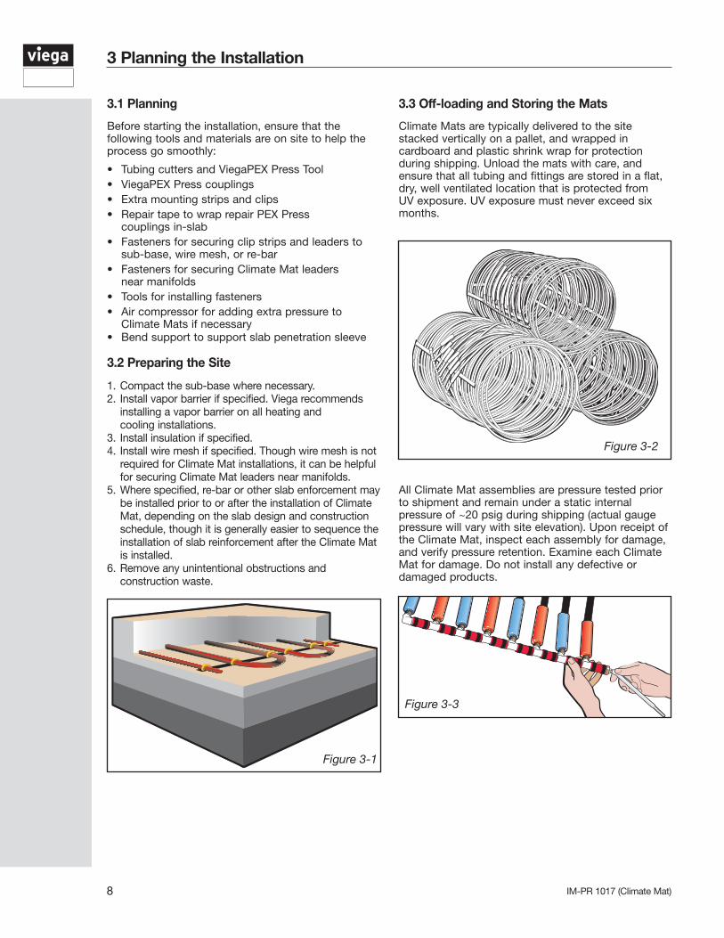
Climate Mats are typically delivered to the site stacked vertically on a pallet, and wrapped in cardboard and plastic shrink wrap for protection during shipping. Unload the mats with care, and ensure that all tubing and fittings are stored in a flat, dry, well ventilated location that is protected from UV exposure. UV exposure must never exceed six months.
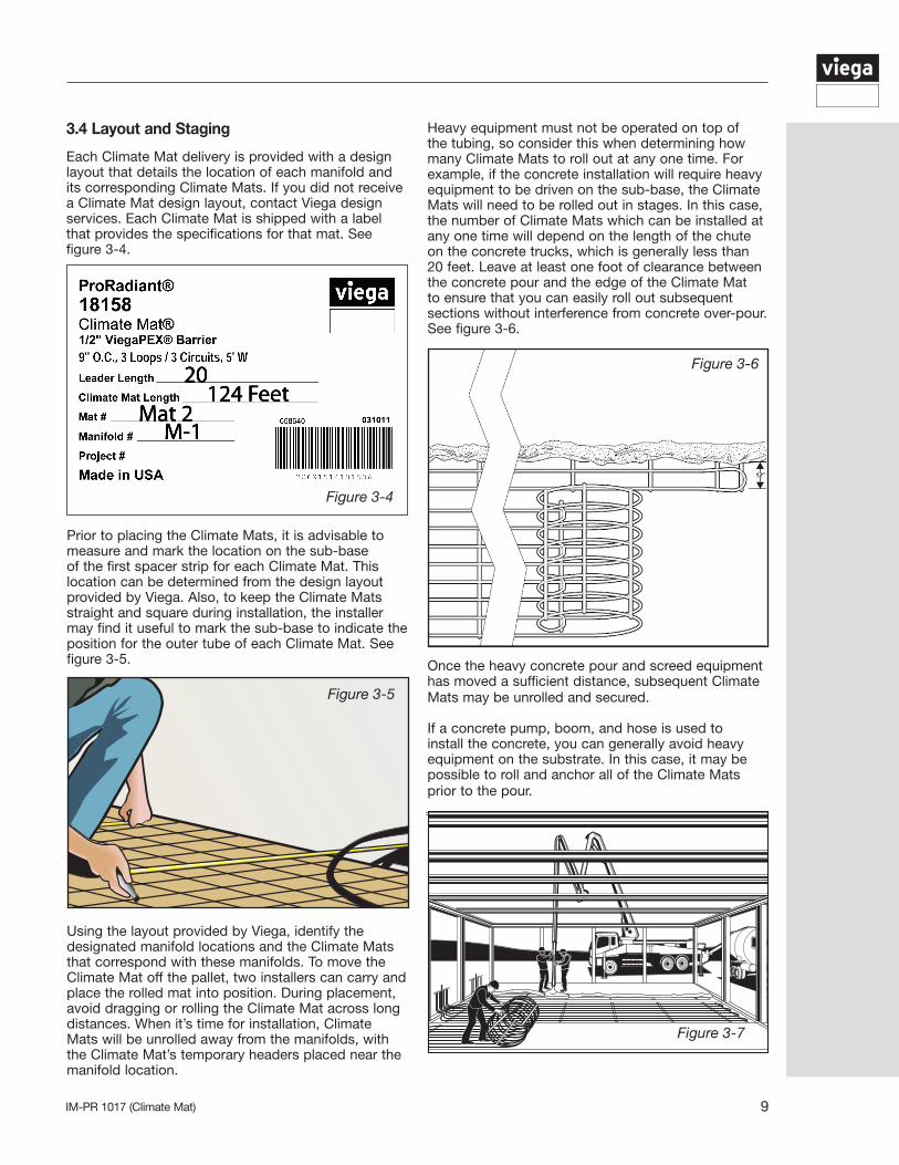
All Climate Mat assemblies are pressure tested prior to shipment and remain under a static internal pressure of ~20 psig during shipping (actual gauge pressure will vary with site elevation). Upon receipt of the Climate Mat, inspect each assembly for damage, and verify pressure retention. Examine each Climate Mat for damage. Do not install any defective or damaged products.
3 Planning the Installation
Figure 3-1
Figure 3-2
Figure 3-3
3.1 Planning
Before starting the installation, ensure that the following tools and materials are on site to help the process go smoothly:
• Tubing cutters and ViegaPEX Press Tool• ViegaPEX Press couplings• Extra mounting strips and clips• Repair tape to wrap repair PEX Press couplings in-slab• Fasteners for securing clip strips and leaders to sub-base, wire mesh, or re-bar• Fasteners for securing Climate Mat leaders near manifolds • Tools for installing fasteners• Air compressor for adding extra pressure to Climate Mats if necessary• Bend support to support slab penetration sleeve
3.2 Preparing the Site
1. Compact the sub-base where necessary. 2. Install vapor barrier if specified. Viega recommends installing a vapor barrier on all heating and cooling installations. 3. Install insulation if specified. 4. Install wire mesh if specified. Though wire mesh is not required for Climate Mat installations, it can be helpful for securing Climate Mat leaders near manifolds.5. Where specified, re-bar or other slab enforcement may be installed prior to or after the installation of Climate Mat, depending on the slab design and construction schedule, though it is generally easier to sequence the installation of slab reinforcement after the Climate Mat is installed.6. Remove any unintentional obstructions and construction waste.
9IM-PR 1017 (Climate Mat)
Heavy equipment must not be operated on top of the tubing, so consider this when determining how many Climate Mats to roll out at any one time. For example, if the concrete installation will require heavy equipment to be driven on the sub-base, the Climate Mats will need to be rolled out in stages. In this case, the number of Climate Mats which can be installed at any one time will depend on the length of the chute on the concrete trucks, which is generally less than 20 feet. Leave at least one foot of clearance between the concrete pour and the edge of the Climate Mat to ensure that you can easily roll out subsequent sections without interference from concrete over-pour. See figure 3-6.
Once the heavy concrete pour and screed equipment has moved a sufficient distance, subsequent Climate Mats may be unrolled and secured.
If a concrete pump, boom, and hose is used to install the concrete, you can generally avoid heavy equipment on the substrate. In this case, it may be possible to roll and anchor all of the Climate Mats prior to the pour.
Using the layout provided by Viega, identify the designated manifold locations and the Climate Mats that correspond with these manifolds. To move the Climate Mat off the pallet, two installers can carry and place the rolled mat into position. During placement, avoid dragging or rolling the Climate Mat across long distances. When it’s time for installation, Climate Mats will be unrolled away from the manifolds, with the Climate Mat’s temporary headers placed near the manifold location.
Figure 3-5
Figure 3-6
Figure 3-7
Prior to placing the Climate Mats, it is advisable to measure and mark the location on the sub-base of the first spacer strip for each Climate Mat. This location can be determined from the design layout provided by Viega. Also, to keep the Climate Mats straight and square during installation, the installer may find it useful to mark the sub-base to indicate the position for the outer tube of each Climate Mat. See figure 3-5.
20124 Feet
Mat 2M-1
3.4 Layout and Staging
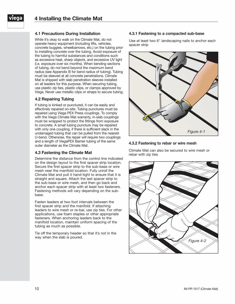
Each Climate Mat delivery is provided with a design layout that details the location of each manifold and its corresponding Climate Mats. If you did not receive a Climate Mat design layout, contact Viega design services. Each Climate Mat is shipped with a label that provides the specifications for that mat. See figure 3-4.
Figure 3-4
IM-PR 1017 (Climate Mat)10
4 Installing the Climate Mat
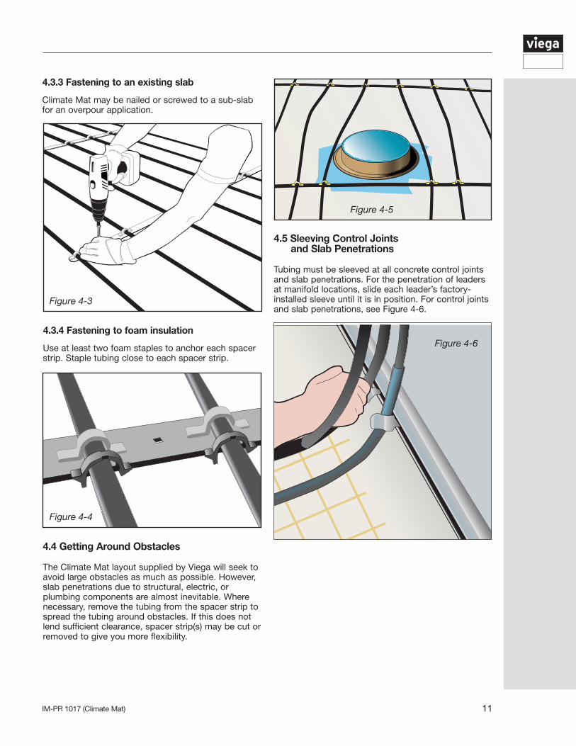
4.3.2 Fastening to rebar or wire mesh
Climate Mat can also be secured to wire mesh or rebar with zip ties
4.3.1 Fastening to a compacted sub-base
Use at least two 6" landscaping nails to anchor each spacer strip
4.1 Precautions During InstallationWhile it’s okay to walk on the Climate Mat, do not operate heavy equipment (including lifts, vehicles, concrete buggies, wheelbarrows, etc.) on the tubing prior to installing concrete over the tubing. Avoid exposure of the tubing to harmful substances and conditions such as excessive heat, sharp objects, and excessive UV light (i.e. exposure over six months). When bending sections of tubing, do not bend beyond the maximum bend radius (see Appendix B for bend radius of tubing). Tubing must be sleeved at all concrete penetrations. Climate Mat is shipped with slab penetration sleeves installed on all leaders for this purpose. When securing tubing, use plastic zip ties, plastic clips, or clamps approved by Viega. Never use metallic clips or straps to secure tubing.
4.2 Repairing Tubing If tubing is kinked or punctured, it can be easily and effectively repaired on-site. Tubing punctures must be repaired using Viega PEX Press couplings. To comply with the Viega Climate Mat warranty, in-slab couplings must be wrapped to protect the fittings from exposure to concrete. A small tubing puncture may be repaired with only one coupling, if there is sufficient slack in the undamaged tubing that can be pulled from the nearest U-bend. Otherwise, the repair will require two couplings and a length of ViegaPEX Barrier tubing of the same outer diameter as the Climate Mat.
4.3 Fastening the Climate MatDetermine the distance from the control line indicated on the design layout to the first spacer strip location. Secure the first spacer strip to the sub-base or wire mesh near the manifold location. Fully unroll the Climate Mat and pull it hand-tight to ensure that it is straight and square. Attach the last spacer strip to the sub-base or wire mesh, and then go back and anchor each spacer strip with at least two fasteners. Fastening methods will vary depending on the sub-base.
Fasten leaders at two foot intervals between the first spacer strip and the manifold. If attaching leaders to wire mesh or re-bar, use zip ties. For other applications, use foam staples or other appropriate fasteners. When anchoring leaders back to the manifold location, maintain uniform spacing of the tubing as much as possible. Tie off the temporary header so that it’s not in the way when the slab is poured.
Figure 4-1
Figure 4-2
11IM-PR 1017 (Climate Mat)
4.4 Getting Around Obstacles
The Climate Mat layout supplied by Viega will seek to avoid large obstacles as much as possible. However, slab penetrations due to structural, electric, or plumbing components are almost inevitable. Where necessary, remove the tubing from the spacer strip to spread the tubing around obstacles. If this does not lend sufficient clearance, spacer strip(s) may be cut or removed to give you more flexibility.
4.5 Sleeving Control Joints and Slab Penetrations
Tubing must be sleeved at all concrete control joints and slab penetrations. For the penetration of leaders at manifold locations, slide each leader’s factory-installed sleeve until it is in position. For control joints and slab penetrations, see Figure 4-6.
4.3.3 Fastening to an existing slab
Climate Mat may be nailed or screwed to a sub-slab for an overpour application.
4.3.4 Fastening to foam insulation
Use at least two foam staples to anchor each spacer strip. Staple tubing close to each spacer strip.
Figure 4-3
Figure 4-4
Figure 4-5
Figure 4-6
IM-PR 1017 (Climate Mat)12
4.7 Connecting to Permanent Manifolds
Permanent manifolds can be installed when the Climate Mats are installed or later in the construction process after the slab has cured. Manifold locations are designated on the Viega design layout for each project. Ensure that manifolds are in locations that will remain easily accessible (e.g. Manifold cabinet). Manifolds must be protected from freezing temperatures, so sufficient insulation must be provided.
Release air pressure from the mats. With a tubing cutter, trim the Climate Mat leaders squarely to the proper length at the manifold location, and discard the temporary header. To maintain the product warranty, use only Viega manifolds and fittings to connect the Climate Mat leaders to the manifolds. Viega recommends a shutoff valve at each circuit for isolation. In addition, each manifold should have an isolation ball valve on the supply and return headers. Climate Mat leaders are color coded to help you distinguish between supply and return. Ensure that all of the manifolds are connected with the same color scheme for supply and return throughout the installation.
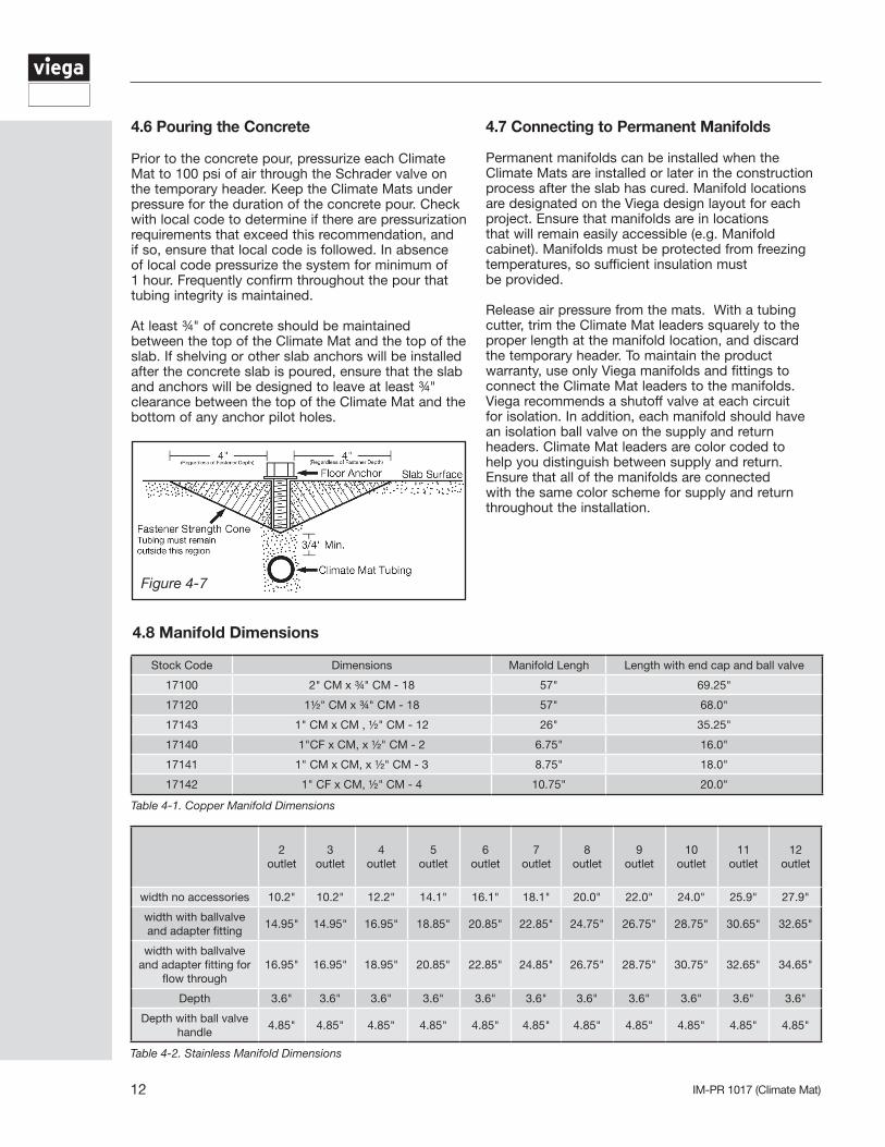
4.6 Pouring the Concrete
Prior to the concrete pour, pressurize each Climate Mat to 100 psi of air through the Schrader valve on the temporary header. Keep the Climate Mats under pressure for the duration of the concrete pour. Check with local code to determine if there are pressurization requirements that exceed this recommendation, and if so, ensure that local code is followed. In absence of local code pressurize the system for minimum of 1 hour. Frequently confirm throughout the pour that tubing integrity is maintained.
At least ¾" of concrete should be maintained between the top of the Climate Mat and the top of the slab. If shelving or other slab anchors will be installed after the concrete slab is poured, ensure that the slab and anchors will be designed to leave at least ¾" clearance between the top of the Climate Mat and the bottom of any anchor pilot holes.
Figure 4-7
Stock Code Dimensions Manifold Lengh Length with end cap and ball valve
17100 2" CM x ¾" CM - 18 57" 69.25"
17120 1½" CM x ¾" CM - 18 57" 68.0"
17143 1" CM x CM , ½" CM - 12 26" 35.25"
17140 1"CF x CM, x ½" CM - 2 6.75" 16.0"
17141 1" CM x CM, x ½" CM - 3 8.75" 18.0"
17142 1" CF x CM, ½" CM - 4 10.75" 20.0"
Table 4-1. Copper Manifold Dimensions
2 outlet
3 outlet
4 outlet
5 outlet
6 outlet
7 outlet
8 outlet
9 outlet
10 outlet
11 outlet
12 outlet
width no accessories 10.2" 10.2" 12.2" 14.1" 16.1" 18.1" 20.0" 22.0" 24.0" 25.9" 27.9"
width with ballvalve and adapter fitting
14.95" 14.95" 16.95" 18.85" 20.85" 22.85" 24.75" 26.75" 28.75" 30.65" 32.65"
width with ballvalve and adapter fitting for
flow through16.95" 16.95" 18.95" 20.85" 22.85" 24.85" 26.75" 28.75" 30.75" 32.65" 34.65"
Depth 3.6" 3.6" 3.6" 3.6" 3.6" 3.6" 3.6" 3.6" 3.6" 3.6" 3.6"
Depth with ball valve handle
4.85" 4.85" 4.85" 4.85" 4.85" 4.85" 4.85" 4.85" 4.85" 4.85" 4.85"
Table 4-2. Stainless Manifold Dimensions
4.8 Manifold Dimensions
13IM-PR 1017 (Climate Mat)
Stock Code
Interior box dimension
Exterior box
dimension
1¼" stainless steel manifold with no
accessories
1¼" stainless steel manifold with ball
valve set
1¼" stainless steel manifold with ball valve set and
adapters for flow through
1¼" stainless steel Manifold with
no Accessories and Zone Control
1¼" stainless steel manifold with ball
valve set and Zone Control
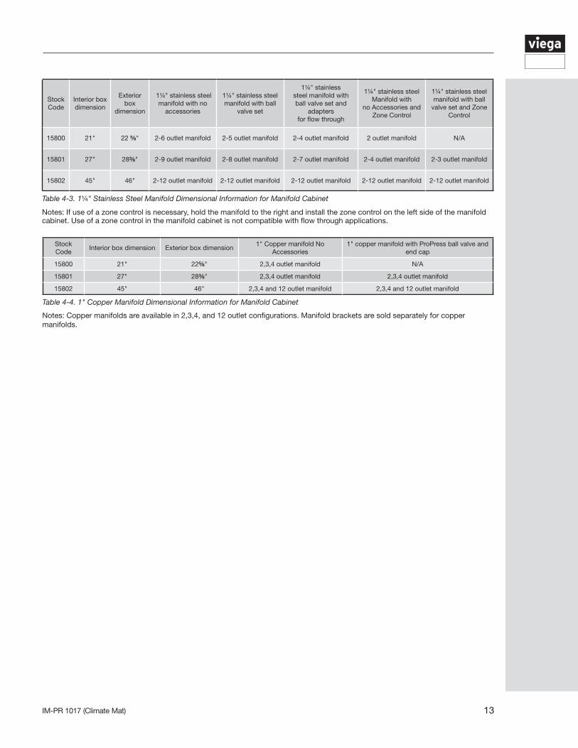
15800 21" 22 ⅝" 2-6 outlet manifold 2-5 outlet manifold 2-4 outlet manifold 2 outlet manifold N/A
15801 27" 28⅜" 2-9 outlet manifold 2-8 outlet manifold 2-7 outlet manifold 2-4 outlet manifold 2-3 outlet manifold
15802 45" 46" 2-12 outlet manifold 2-12 outlet manifold 2-12 outlet manifold 2-12 outlet manifold 2-12 outlet manifold
Table 4-3. 1¼" Stainless Steel Manifold Dimensional Information for Manifold Cabinet
Notes: If use of a zone control is necessary, hold the manifold to the right and install the zone control on the left side of the manifold cabinet. Use of a zone control in the manifold cabinet is not compatible with flow through applications.
Stock Code
Interior box dimension Exterior box dimension1" Copper manifold No
Accessories1" copper manifold with ProPress ball valve and
end cap
15800 21" 22⅝" 2,3,4 outlet manifold N/A
15801 27" 28⅜" 2,3,4 outlet manifold 2,3,4 outlet manifold
15802 45" 46" 2,3,4 and 12 outlet manifold 2,3,4 and 12 outlet manifold
Table 4-4. 1" Copper Manifold Dimensional Information for Manifold Cabinet
Notes: Copper manifolds are available in 2,3,4, and 12 outlet configurations. Manifold brackets are sold separately for copper manifolds.
IM-PR 1017 (Climate Mat)14
5 System Startup
5.1 Purging Procedure
The purging procedure varies based on availability of water.
Assuming water for filling and purging is provided by the primary loop makeup water system:
1. With manifold connected, close all manifold circuit valves.2. Close isolation ball valve on the return header.3. Attach a drain hose to the return header drain valve.4. Open circuit shutoff valves on supply and return headers for 1st circuit to purge & fill this circuit.5. Once purge & fill for 1st circuit is complete, close circuit shutoff valves on supply and return headers.6. Repeat steps 4 & 5 for each additional circuit, one at a time.7. Once last circuit is purged & filled, close last circuit shutoff valve.8. Open all circuit shutoff valves on supply & return headers.9. Close drain valve.
Where water for filling and purging is not provided from primary piping:
1. Close isolation ball valves on supply and return headers2. Connect fill hose/purge water source to drain valve on supply header.3. Attach a drain hose to the return header drain valve.4. Open drain valve on supply header to start water flow into supply header.5. Steps 5-9 are the same as if water fill is from primary system.10. Close drain valve on supply header.
Precautions should be taken to keep the system from freezing. Ensure the proper amount of glycol is on site for mixing. Mix ratio should not exceed 50%. Premix glycol ahead of time before adding to the system.
Note: steps above would be the same for the addition of glycol.
When starting up the system in heating mode, it is best to warm the thermal mass up slowly to help prevent possible shock to the slab. In accordance with DIN 4725 section 4, Viega recommends:
• Start warm up after concrete has reached its final set (curing complete).• Set supply water temperature to 77°F for the first three days.• Increase supply water temperature to the set point in gradual increments for the next four days (maximum of a 50°F increase in a period of 24 hours).• Slab warm up should follow the concrete manufacturer’s recommendations.
15IM-PR 1017 (Climate Mat)
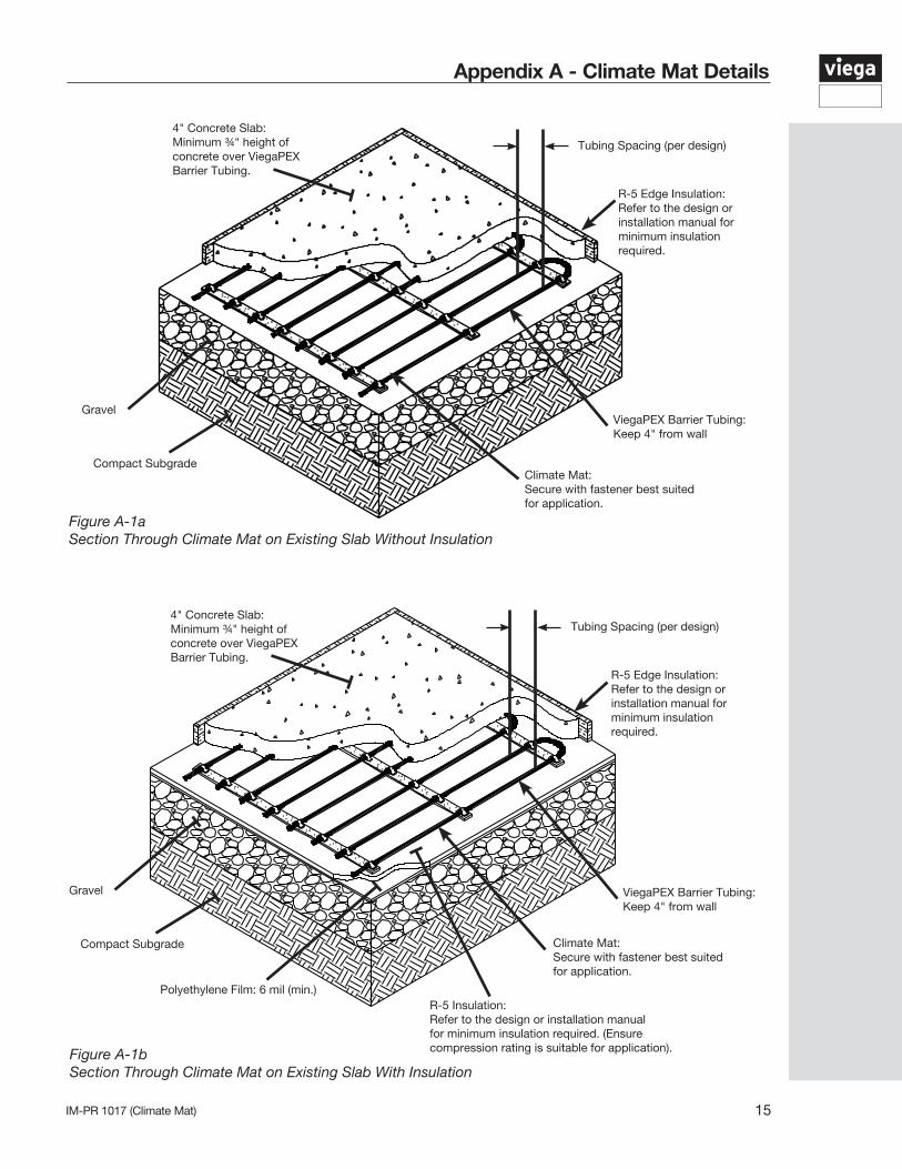
Appendix A - Climate Mat Details
Figure A-1aSection Through Climate Mat on Existing Slab Without Insulation
4" Concrete Slab: Minimum ¾" height of concrete over ViegaPEX Barrier Tubing.
Climate Mat:Secure with fastener best suited for application.
Tubing Spacing (per design)
Compact Subgrade
GravelViegaPEX Barrier Tubing: Keep 4" from wall
R-5 Edge Insulation:Refer to the design or installation manual for minimum insulation required.
Figure A-1bSection Through Climate Mat on Existing Slab With Insulation
4" Concrete Slab: Minimum ¾" height of concrete over ViegaPEX Barrier Tubing.
Climate Mat:Secure with fastener best suited for application.
Tubing Spacing (per design)
Compact Subgrade
Gravel ViegaPEX Barrier Tubing: Keep 4" from wall
R-5 Edge Insulation:Refer to the design or installation manual for minimum insulation required.
Polyethylene Film: 6 mil (min.)R-5 Insulation:Refer to the design or installation manual for minimum insulation required. (Ensure compression rating is suitable for application).
IM-PR 1017 (Climate Mat)16
Appendix B - ViegaPEX Barrier Tubing
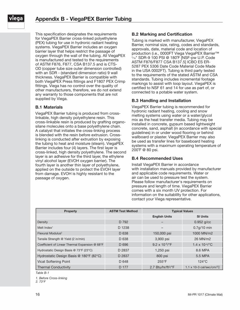
This specification designates the requirements for ViegaPEX Barrier cross-linked polyethylene (PEX) tubing for use in hydronic radiant heating systems. ViegaPEX Barrier includes an oxygen barrier layer that helps restrict the passage of oxygen through the wall of the tubing. All ViegaPEX is manufactured and tested to the requirements of ASTM F876, F877, CSA B137.5 and is CTS-OD (copper tube size outer dimension controlled) with an SDR - (standard dimension ratio) 9 wall thickness. ViegaPEX Barrier is compatible with both ViegaPEX Press fittings and F1807 PEX Crimp fittings. Viega has no control over the quality of other manufacturers, therefore, we do not extend any warranty to those components that are not supplied by Viega.
B.1 MaterialsViegaPEX Barrier tubing is produced from cross-linkable, high density polyethylene resin. This cross-linkable resin is produced by grafting organo-silane molecules onto a base polyethylene chain. A catalyst that initiates the cross-linking process is blended with the resin before extrusion. Cross-linking is conducted after extrustion by exposing the tubing to heat and moisture (steam). ViegaPEX Barrier includes four (4) layers. The first layer is cross-linked, high density polyethylene. The second layer is an adhesive for the third layer, the ethylene vinyl alcohol layer (EVOH oxygen barrier). The fourth layer is another thin layer of polyethylene, applied on the outside to protect the EVOH layer from damage. EVOH is highly resistant to the passage of oxygen.
B.2 Marking and CertificationTubing is marked with manufacturer, ViegaPEX Barrier, nominal size, rating, codes and standards, approvals, date, material code and location of production (i.e., 0000FT Viega ViegaPEX Barrier™ 5/16" SDR-9 100 PSI @ 180˚F [NSF-pw U.P. Code ASTM F876/F877 CSA B137.5] ICBO ES ER-5287 PEX 5306 Date Code Material Code Made in the USA 0002FT). Tubing is third party tested to the requirements of the stated ASTM and CSA standards. Tubing includes incremental footage markings to assist with loop layout. ViegaPEX is certified to NSF 61 and 14 for use as part of, or connected to a potable water system.
B.3 Handling and InstallationViegaPEX Barrier tubing is recommended for hydronic radiant heating, cooling and snow melting systems using water or a water/glycol mix as the heat transfer media. Tubing may be installed in concrete, gypsum based lightweight concrete, sand, asphalt (in accordance with special guidelines) in or under wood flooring or behind wallboard or plaster. ViegaPEX Barrier may also be used as transfer lines for baseboard heating systems with a maximum operating temperature of 200˚F @ 80 psi.
B.4 Recommended UsesInstall ViegaPEX Barrier in accordance with installation manuals provided by manufacturer and applicable code requirements. Water or air can be used to pressure test the system. Please follow manufacturer's requirements on pressure and length of time. ViegaPEX Barrier comes with a six month UV protection. For information on the suitablilty for other applications, contact your Viega representative.
Property ASTM Test Method Typical Values
English Units SI Units
Density D 792 – 0.952 g/cc
Melt Index1 D 1238 – 0.7g/10 min
Flexural Modulus2 D 638 150,000 psi 1000 MN/m2
Tensile Strength @ Yield (2 in/min) D 638 3,900 psi 26 MN/m2
Coefficient of Linear Thermal Expansion @ 68°F D 696 9.2 x 10⁻⁵/°F 1.4 x 10⁻⁴/°C
Hydrostatic Design Basis @ 73°F (23°C) D 2837 1,250 psi 8.6 MPA
Hydrostatic Design Basis @ 180°F (82°C) D 2837 800 psi 5.5 MPA
Vicat Softening Point D 648 255°F 124°C
Thermal Conductivity D 177 2.7 Btu/hr/ft2/°F 1.1 x 10⁻³ cal/sec/cm/˚C
Table B-1
1. Before Cross-linking2. 73°F
17IM-PR 1017 (Climate Mat)
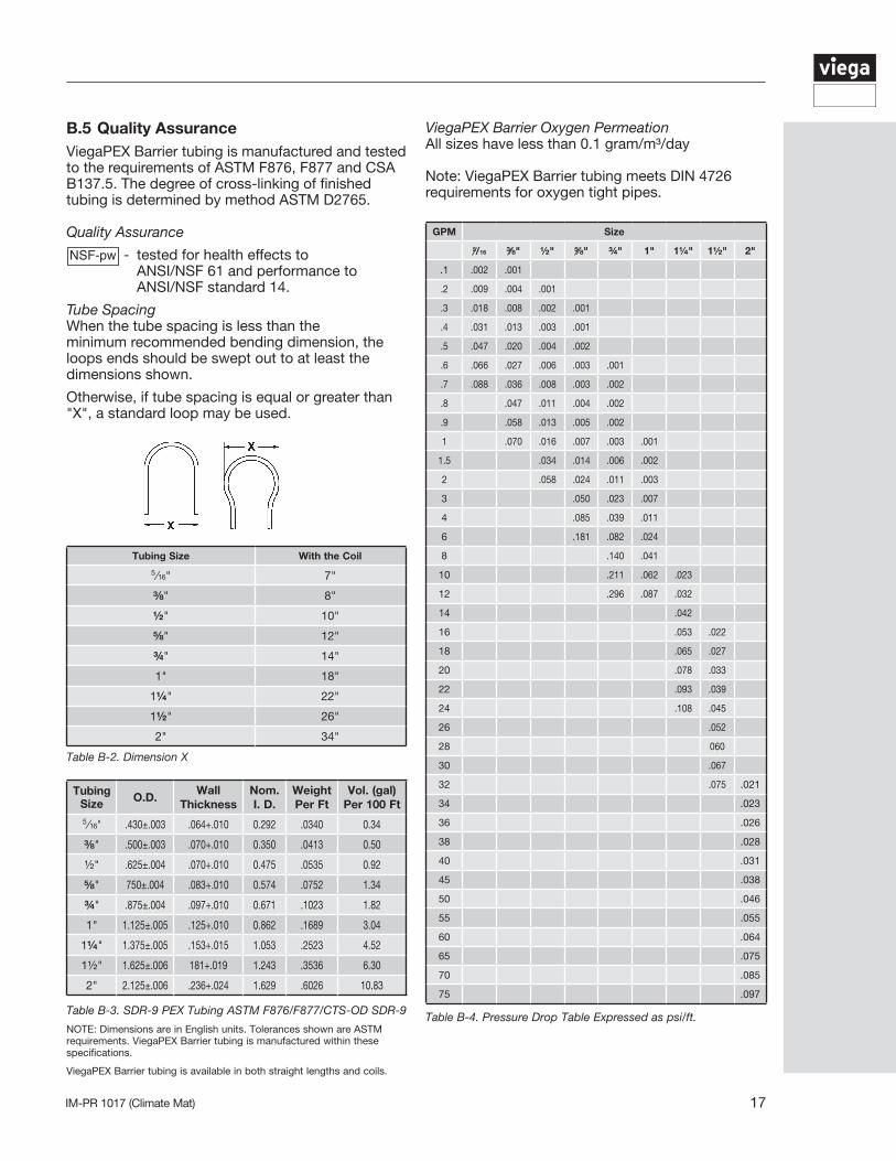
B.5 Quality AssuranceViegaPEX Barrier tubing is manufactured and tested to the requirements of ASTM F876, F877 and CSA B137.5. The degree of cross-linking of finished tubing is determined by method ASTM D2765.
Quality Assurance
- tested for health effects to ANSI/NSF 61 and performance to ANSI/NSF standard 14.
Tube SpacingWhen the tube spacing is less than the minimum recommended bending dimension, the loops ends should be swept out to at least the dimensions shown.
Otherwise, if tube spacing is equal or greater than "X", a standard loop may be used.
ViegaPEX Barrier Oxygen PermeationAll sizes have less than 0.1 gram/m³/day
Note: ViegaPEX Barrier tubing meets DIN 4726 requirements for oxygen tight pipes.
Tubing Size With the Coil
5/16" 7"
⅜" 8"
½" 10"
⅝" 12"
¾" 14"
1" 18"
1¼" 22"
1½" 26"
2" 34"
Table B-2. Dimension X
Tubing Size O.D.
Wall Thickness
Nom. I. D.
Weight Per Ft
Vol. (gal) Per 100 Ft
5/16" .430±.003 .064+.010 0.292 .0340 0.34
⅜" .500±.003 .070+.010 0.350 .0413 0.50
½" .625±.004 .070+.010 0.475 .0535 0.92
⅝" 750±.004 .083+.010 0.574 .0752 1.34
¾" .875±.004 .097+.010 0.671 .1023 1.82
1" 1.125±.005 .125+.010 0.862 .1689 3.04
1¼" 1.375±.005 .153+.015 1.053 .2523 4.52
1½" 1.625±.006 181+.019 1.243 .3536 6.30
2" 2.125±.006 .236+.024 1.629 .6026 10.83
Table B-3. SDR-9 PEX Tubing ASTM F876/F877/CTS-OD SDR-9
NOTE: Dimensions are in English units. Tolerances shown are ASTM requirements. ViegaPEX Barrier tubing is manufactured within these specifications.
ViegaPEX Barrier tubing is available in both straight lengths and coils.
GPM Size
5/16 ⅜" ½" ⅝" ¾" 1" 1¼" 1½" 2"
.1 .002 .001
.2 .009 .004 .001
.3 .018 .008 .002 .001
.4 .031 .013 .003 .001
.5 .047 .020 .004 .002
.6 .066 .027 .006 .003 .001
.7 .088 .036 .008 .003 .002
.8 .047 .011 .004 .002
.9 .058 .013 .005 .002
1 .070 .016 .007 .003 .001
1.5 .034 .014 .006 .002
2 .058 .024 .011 .003
3 .050 .023 .007
4 .085 .039 .011
6 .181 .082 .024
8 .140 .041
10 .211 .062 .023
12 .296 .087 .032
14 .042
16 .053 .022
18 .065 .027
20 .078 .033
22 .093 .039
24 .108 .045
26 .052
28 060
30 .067
32 .075 .021
34 .023
36 .026
38 .028
40 .031
45 .038
50 .046
55 .055
60 .064
65 .075
70 .085
75 .097
Table B-4. Pressure Drop Table Expressed as psi/ft.
IM-PR 1017 (Climate Mat)18
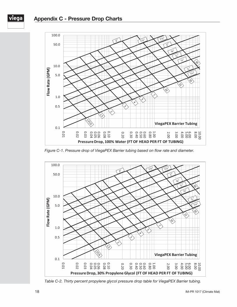
Appendix C - Pressure Drop Charts
Figure C-1. Pressure drop of ViegaPEX Barrier tubing based on flow rate and diameter.
Table C-2. Thirty percent propylene glycol pressure drop table for ViegaPEX Barrier tubing.
1½" 1¼"
¾"
5 8"
½"
3 8"
5 ⁄16"
1½" 1¼"
¾"
½"
5 8"
5 ⁄16"
3 8"
19IM-PR 1017 (Climate Mat)
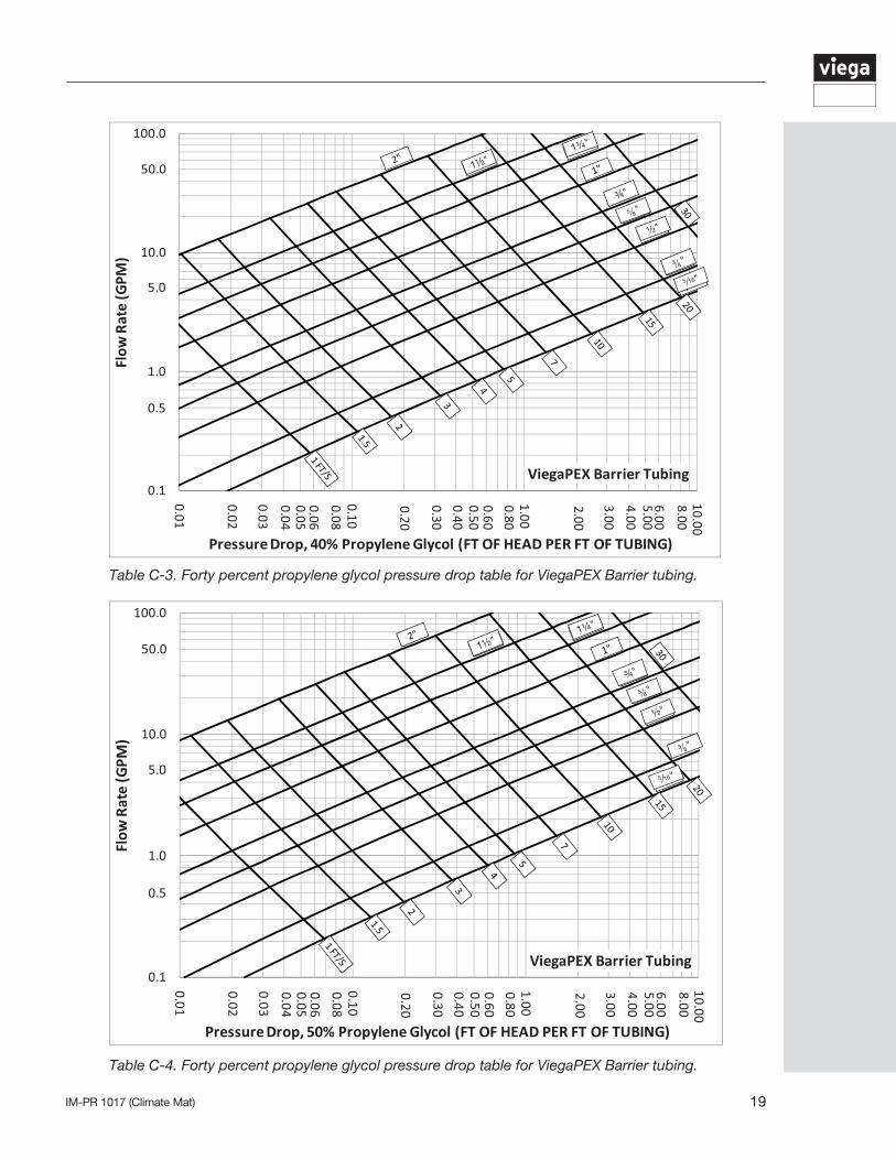
Table C-3. Forty percent propylene glycol pressure drop table for ViegaPEX Barrier tubing.
¾"
½"
5 ⁄16"
5 8"
1½"
3 8"
1¼"
¾"
½"
5 ⁄16"
5 8"
3 8"
1¼"
1½"
Table C-4. Forty percent propylene glycol pressure drop table for ViegaPEX Barrier tubing.
IM-PR 1017 (Climate Mat)20
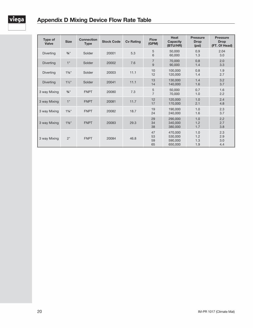
Appendix D Mixing Device Flow Rate Table
Type of Valve
SizeConnection
TypeStock Code Cv Rating
Flow (GPM)
Heat Capacity (BTU/HR)
Pressure Drop (psi)
Pressure Drop
(FT. Of Head)
Diverting ¾" Solder 20001 5.35 6
50,000 60,000
0.9 1.3
2.04 3.0
Diverting 1" Solder 20002 7.67 9
70,000 90,000
0.8 1.4
2.0 3.3
Diverting 1¼" Solder 20003 11.110 12
100,000 120,000
0.8 1.4
1.9 2.7
Diverting 1½" Solder 20041 11.113 14
130,000 140,000
1.4 1.6
3.2 3.7
3 way Mixing ¾" FNPT 20080 7.35 7
50,000 70,000
0.7 1.0
1.6 2.2
3 way Mixing 1" FNPT 20081 11.712 17
120,000 170,000
1.0 2.1
2.4 4.8
3 way Mixing 1¼" FNPT 20082 18.719 24
190,000 240,000
1.0 1.6
2.3 3.7
3 way Mixing 1½" FNPT 20083 29.329 34 38
290,000 340,000 380,000
1.0 1.2 1.7
2.2 2.7 3.8
3 way Mixing 2" FNPT 20084 46.8
47 53 59 65
470,000 530,000 590,000 650,000
1.0 1.2 1.3 1.9
2.3 2.9 3.0 4.4
21IM-PR 1017 (Climate Mat)
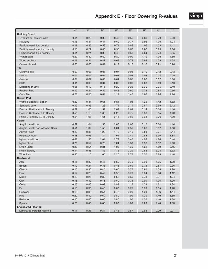
Appendix E - Floor Covering R-values
⅛" ¼" ⅜" ½" ⅝" ¾" ⅜" 1" Building Board
Gypsum or Plaster Board 0.11 0.23 0.32 0.45 0.56 0.68 0.79 0.90
Plywood 0.16 0.31 0.47 0.62 0.77 0.93 1.09 1.24
Particleboard, low density 0.18 0.35 0.53 0.71 0.88 1.06 1.23 1.41
Particleboard, medium density 0.13 0.27 0.40 0.53 0.66 0.80 0.93 1.06
Particleboard, high density 0.11 0.21 0.32 0.43 0.53 0.64 0.74 0.85
Waferboard 0.20 0.40 0.60 0.80 0.99 1.19 1.39 1.59
Wood subfloor 0.16 0.31 0.47 0.62 0.78 0.93 1.09 1.24
Cement board 0.03 0.06 0.09 0.12 0.15 0.18 0.21 0.24
Tile Ceramic Tile 0.02 0.03 0.05 0.07 0.08 0.10 0.12 0.13
Marble 0.01 0.01 0.02 0.03 0.03 0.04 0.04 0.05
Granite 0.01 0.02 0.03 0.04 0.05 0.06 0.07 0.08
Slate 0.01 0.03 0.04 0.05 0.06 0.08 0.09 0.10
Linoleum or Vinyl 0.05 0.10 0.15 0.20 0.25 0.30 0.35 0.40
Rubber, hard 0.12 0.24 0.36 0.48 0.60 0.72 0.84 0.96
Cork Tile 0.28 0.56 0.84 1.12 1.40 1.68 1.96 2.24
Carpet PadWaffled Sponge Rubber 0.20 0.41 0.61 0.81 1.01 1.22 1.42 1.62
Synthetic Jute 0.43 0.86 1.28 1.71 2.14 2.57 2.99 3.42
Bonded Urethane, 4 lb Density 0.52 1.05 1.57 2.09 2.61 3.14 3.66 4.18
Bonded Urethane, 8 lb Density 0.55 1.10 1.65 2.20 2.75 3.30 3.85 4.40
Prime Urethane, 2.2 lb Density 0.54 1.08 1.61 2.15 2.69 3.23 3.76 4.30
CarpetAcrylic Level Loop 0.52 1.04 1.56 2.08 2.60 3.12 3.64 4.16
Acrylic Level Loop w/Foam Back 0.51 1.02 1.53 2.04 2.55 3.06 3.57 4.08
Acrylic Plush 0.43 0.86 1.29 1.72 2.15 2.58 3.01 3.44
Polyester Plush 0.48 0.96 1.44 1.92 2.40 2.88 3.36 3.84
Nylon Level Loop 0.68 1.36 2.04 2.72 3.40 4.08 4.76 5.44
Nylon Plush 0.26 0.52 0.78 1.04 1.30 1.56 1.82 2.08
Nylon Shag 0.27 0.54 0.81 1.08 1.35 1.62 1.89 2.16
Nylon Saxony 0.44 0.88 1.32 1.76 2.20 2.64 3.08 3.52
Wool Plush 0.55 1.10 1.65 2.20 2.75 3.30 3.85 4.40
HardwoodAsh 0.15 0.30 0.45 0.60 0.75 0.90 1.05 1.20
Beech 0.12 0.24 0.36 0.48 0.60 0.72 0.84 0.96
Cherry 0.15 0.30 0.45 0.60 0.75 0.90 1.05 1.20
Elm 0.14 0.28 0.42 0.56 0.70 0.84 0.98 1.12
Maple 0.13 0.26 0.39 0.52 0.65 0.78 0.91 1.04
Oak 0.15 0.30 0.45 0.60 0.75 0.90 1.05 1.20
Cedar 0.23 0.46 0.69 0.92 1.15 1.38 1.61 1.84
Fir 0.15 0.30 0.45 0.60 0.75 0.90 1.05 1.20
Hemlock 0.18 0.36 0.54 0.72 0.90 1.08 1.26 1.44
Pine 0.20 0.40 0.60 0.80 1.00 1.20 1.40 1.60
Redwood 0.20 0.40 0.60 0.80 1.00 1.20 1.40 1.60
Spruce 0.20 0.40 0.60 0.80 1.00 1.20 1.40 1.60
Engineered Flooring Laminated Parquet Flooring 0.11 0.23 0.34 0.45 0.57 0.68 0.79 0.91

IM-PR 1017 (Climate Mat)22
Notes

23IM-PR 1017 (Climate Mat)
Notes

IM-PR 1017 (Climate Mat)
Viega LLC12303 Airport Way, Ste. 395 Broomfield, CO 80021 Phone: 1-800-976-9819 Fax: 1-800-976-9817 www.viega.us
This document subject to updates. For the most current Viega technical literature please visit www.viega.us.©2017, Viega®, ProPress®, MegaPress®, SeaPress®, PureFlow®, Smart Connect®, ManaBloc®, GeoFusion®, FostaPEX®, Radiant Wizard®, Climate Panel®, Climate Mat®, and Climate Track® are registered trademarks of Viega GmbH & Co. KG. SmartLoop® and Viega Eco Plus® are registered trademarks of Viega Holding GmbH & Co. Zero Lead™ and PolyAlloy™ are trademarks of Viega LLC. Eco Brass® is a registered trademark of Mitsubishi Shindoh Co., LTD. RIDGID® is a registered trademark of RIDGID, Inc. LoopCAD® is a registered trademark of Avenir Software Inc. Radel® is a registered trademark of Solvay Advanced Polymers, LLC.


![[XLS] for the month Apr... · Web viewMargin MarketType MarketType MarketType MarketType MarketType_Text MarketType_Text Mast Mast Mat Mat Mat Mat Mat Mat Mat Mat Mat Mat Mat Match1](https://img.pdfslide.net/doc/110x75/5ab4774c7f8b9a2f438b92c4/xls-for-the-month-aprweb-viewmargin-markettype-markettype-markettype-markettype.jpg)