Embed Size (px)
Citation preview
ProRadiant™ CombiflexViega's Hydronic Solution Installation Manual 2013
IM-PR-566351 1017 (Combiflex)2
Contents
1 System Advantages and Benefits1.1 Combiflex system concept . . . . . . . . . . . . 31.2 Application benefits . . . . . . . . . . . . . . . . . . 41.3 Manifold/mixing equipment benefits . . . . . 51.4 Tubing . . . . . . . . . . . . . . . . . . . . . . . . . . . . 6
2 Product Description
3 Combiflex System Design3.1 Piping and controls . . . . . . . . . . . . . . . . . 173.2 Wiring schematics . . . . . . . . . . . . . . . . . . 183.3 Basic heating control . . . . . . . . . . . . . . . 203.4 Programming the basic heating control for
the combiflex system . . . . . . . . . . . . . . . . 213.5 The hydronic mixing block for the combiflex
system . . . . . . . . . . . . . . . . . . . . . . . . . . 223.6 ViegaPEX Barrier or Viega FostaPEX . . . . 24 tubing and pump sizing . . . . . . . . . . . . . 24
4 Combiflex Installation4.1 Baseboard connections . . . . . . . . . . . . . 264.2 Handling PEX tubing . . . . . . . . . . . . . . . . 274.3 Wood frame construction . . . . . . . . . . . . 274.4 Steel construction . . . . . . . . . . . . . . . . . . 274.5 Supporting PEX tubing . . . . . . . . . . . . . . 274.6 Electric grounding . . . . . . . . . . . . . . . . . . 284.7 Repairs . . . . . . . . . . . . . . . . . . . . . . . . . . . 28
4.7.1 ViegaPEX repair coupling wrap . . . . 294.8 Concrete construction . . . . . . . . . . . . . . . 304.9 PEX tubing expansion and contraction . 30
5 Mixing Equipment5.1 Assembled mixing station . . . . . . . . . . . . 315.2 Specifications for the base mixing station . . . 335.3 Specifications for the enhanced mixing
station . . . . . . . . . . . . . . . . . . . . . . . . . . . 355.4 High temperature limit . . . . . . . . . . . . . . . 375.5 Specification for hydronic mixing block . 385.6 System start-up for mixing stations. . . . . 395.7 System start-up for hydronic mixing block . . 40
6 PEX Tubing6.1 ViegaPEX Barrier tubing . . . . . . . . . . . . . 416.2 Viega FostaPEX tubing . . . . . . . . . . . . . . 43
Appendix A Making a PEX press connection . . . . . . . . . . . 45Manifold connection - PEX press . . . . . . . . . . 46Manifold connection - compression . . . . . . . . 47
Appendix BMixing equipment piping / wiring . . . . . . . . . . 48
Appendix CPump sizing . . . . . . . . . . . . . . . . . . . . . . . . . . . 52
Viega products are designed to be installed by licensed and trained plumbing and mechanical professionals who are familiar with Viega products and their installation. Installation by non-professionals may void Viega LLC’s warranty.
IM-PR-566351 1017 (Combiflex) 3
1.1 Combiflex system concept
Viega's combiflex system offers greater efficiency and comfort over traditional high temperature systems through the use of:
• Innovations in piping technology • Integration of manifolds• Use of controls
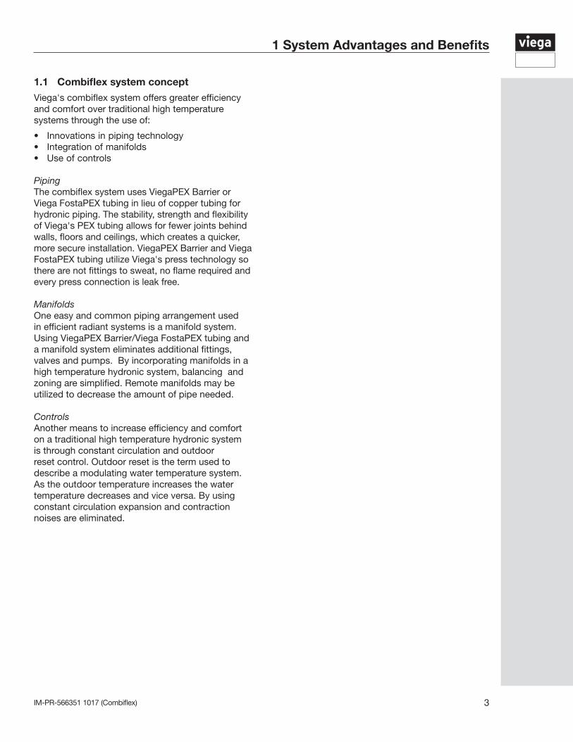
Piping The combiflex system uses ViegaPEX Barrier or Viega FostaPEX tubing in lieu of copper tubing for hydronic piping. The stability, strength and flexibility of Viega's PEX tubing allows for fewer joints behind walls, floors and ceilings, which creates a quicker, more secure installation. ViegaPEX Barrier and Viega FostaPEX tubing utilize Viega's press technology so there are not fittings to sweat, no flame required and every press connection is leak free.
ManifoldsOne easy and common piping arrangement used in efficient radiant systems is a manifold system. Using ViegaPEX Barrier/Viega FostaPEX tubing and a manifold system eliminates additional fittings, valves and pumps. By incorporating manifolds in a high temperature hydronic system, balancing and zoning are simplified. Remote manifolds may be utilized to decrease the amount of pipe needed.
ControlsAnother means to increase efficiency and comfort on a traditional high temperature hydronic system is through constant circulation and outdoor reset control. Outdoor reset is the term used to describe a modulating water temperature system. As the outdoor temperature increases the water temperature decreases and vice versa. By using constant circulation expansion and contraction noises are eliminated.
1 System Advantages and Benefits
IM-PR-566351 1017 (Combiflex)4
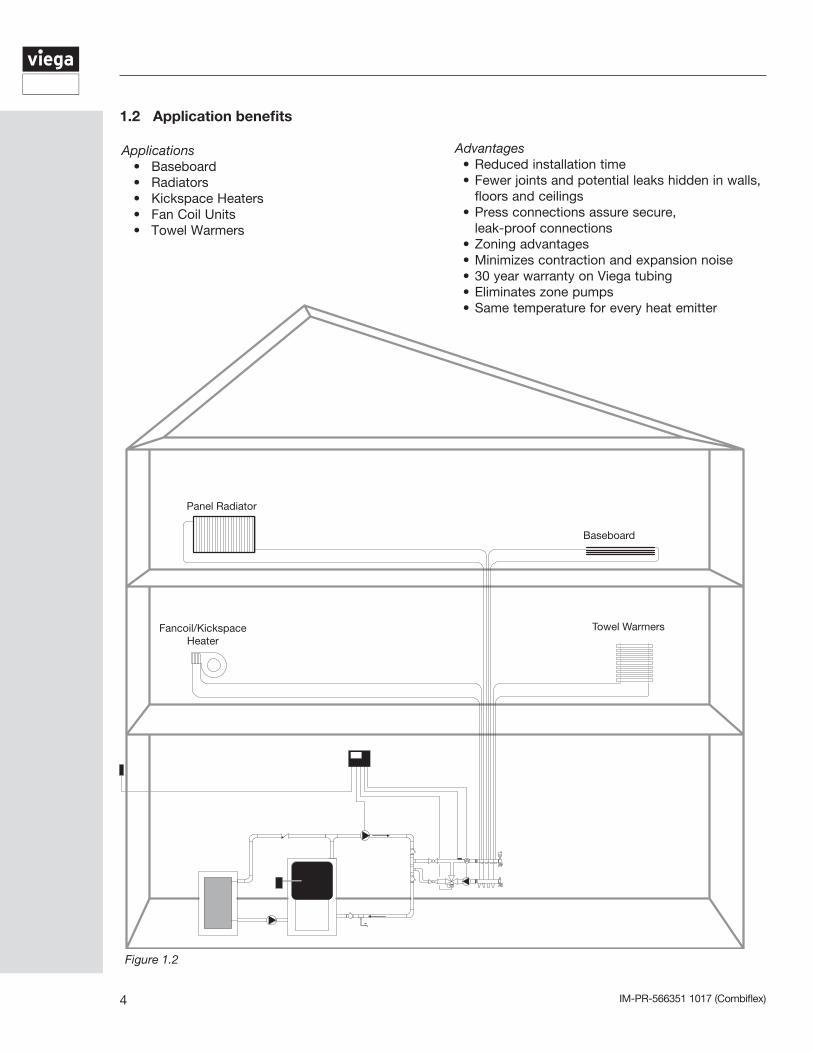
Advantages• Reduced installation time• Fewer joints and potential leaks hidden in walls,
floors and ceilings • Press connections assure secure, leak-proof connections• Zoning advantages• Minimizes contraction and expansion noise• 30 year warranty on Viega tubing• Eliminates zone pumps• Same temperature for every heat emitter
Applications • Baseboard • Radiators • Kickspace Heaters • Fan Coil Units • Towel Warmers
1.2 Application benefits
Figure 1.2
Panel Radiator
Baseboard
Fancoil/Kickspace Heater
Towel Warmers
IM-PR-566351 1017 (Combiflex) 5
1.3 Manifold/mixing equipment benefits
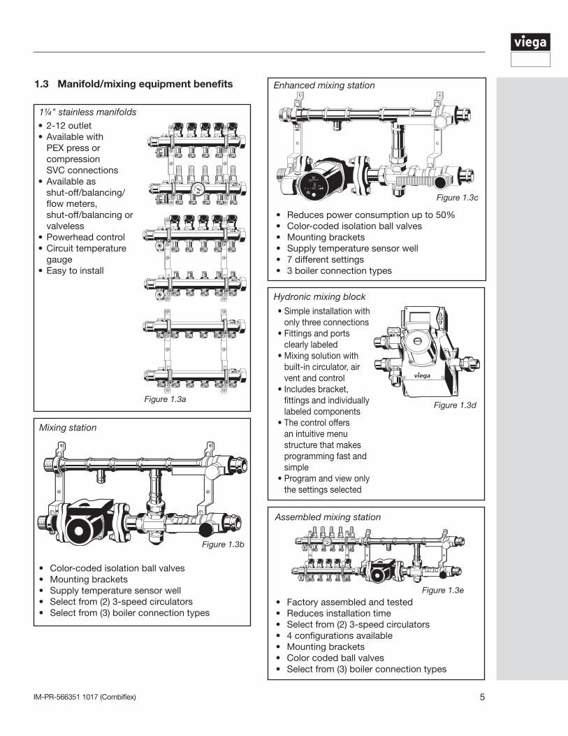
• 2-12 outlet• Available with
PEX press or compression
SVC connections• Available as shut-off/balancing/
flow meters, shut-off/balancing or
valveless• Powerhead control• Circuit temperature
gauge• Easy to install
1¼" stainless manifolds
Figure 1.3a
Enhanced mixing station
• Reduces power consumption up to 50%• Color-coded isolation ball valves• Mounting brackets• Supply temperature sensor well• 7 different settings• 3 boiler connection types
Figure 1.3c
• Simple installation with only three connections
• Fittings and ports clearly labeled
• Mixing solution with built-in circulator, air vent and control
• Includes bracket, fittings and individually labeled components
• The control offers an intuitive menu structure that makes programming fast and simple
• Program and view only the settings selected
Figure 1.3d
• Color-coded isolation ball valves• Mounting brackets• Supply temperature sensor well• Select from (2) 3-speed circulators• Select from (3) boiler connection types
Figure 1.3b
Mixing station
Figure 1.3e• Factory assembled and tested• Reduces installation time• Select from (2) 3-speed circulators• 4 configurations available• Mounting brackets• Color coded ball valves• Select from (3) boiler connection types
Assembled mixing station
Hydronic mixing block
IM-PR-566351 1017 (Combiflex)6
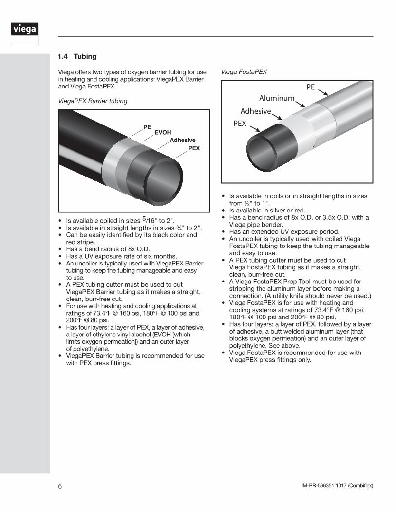
1.4 Tubing
Viega offers two types of oxygen barrier tubing for use in heating and cooling applications: ViegaPEX Barrier and Viega FostaPEX.
PEEVOH
AdhesivePEX
• Is available coiled in sizes 5/16" to 2".• Is available in straight lengths in sizes ¾" to 2".• Can be easily identified by its black color and red stripe.• Has a bend radius of 8x O.D.• Has a UV exposure rate of six months.• An uncoiler is typically used with ViegaPEX Barrier tubing to keep the tubing manageable and easy to use.• A PEX tubing cutter must be used to cut ViegaPEX Barrier tubing as it makes a straight, clean, burr-free cut.• For use with heating and cooling applications at ratings of 73.4°F @ 160 psi, 180°F @ 100 psi and 200°F @ 80 psi.• Has four layers: a layer of PEX, a layer of adhesive, a layer of ethylene vinyl alcohol (EVOH [which limits oxygen permeation]) and an outer layer of polyethylene.• ViegaPEX Barrier tubing is recommended for use with PEX press fittings.
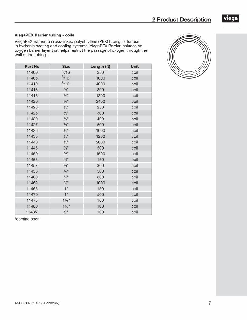
PEX
Adhesive
AluminumPE
ViegaPEX Barrier tubing
Viega FostaPEX
• Is available in coils or in straight lengths in sizes from ½" to 1".• Is available in silver or red.• Has a bend radius of 8x O.D. or 3.5x O.D. with a Viega pipe bender.• Has an extended UV exposure period.• An uncoiler is typically used with coiled Viega
FostaPEX tubing to keep the tubing manageable and easy to use.
• A PEX tubing cutter must be used to cut Viega FostaPEX tubing as it makes a straight, clean, burr-free cut.• A Viega FostaPEX Prep Tool must be used for
stripping the aluminum layer before making a connection. (A utility knife should never be used.)
• Viega FostaPEX is for use with heating and cooling systems at ratings of 73.4°F @ 160 psi, 180°F @ 100 psi and 200°F @ 80 psi.
• Has four layers: a layer of PEX, followed by a layer of adhesive, a butt welded aluminum layer (that blocks oxygen permeation) and an outer layer of polyethylene. See above.• Viega FostaPEX is recommended for use with
ViegaPEX press fittings only.
IM-PR-566351 1017 (Combiflex) 7
2 Product Description
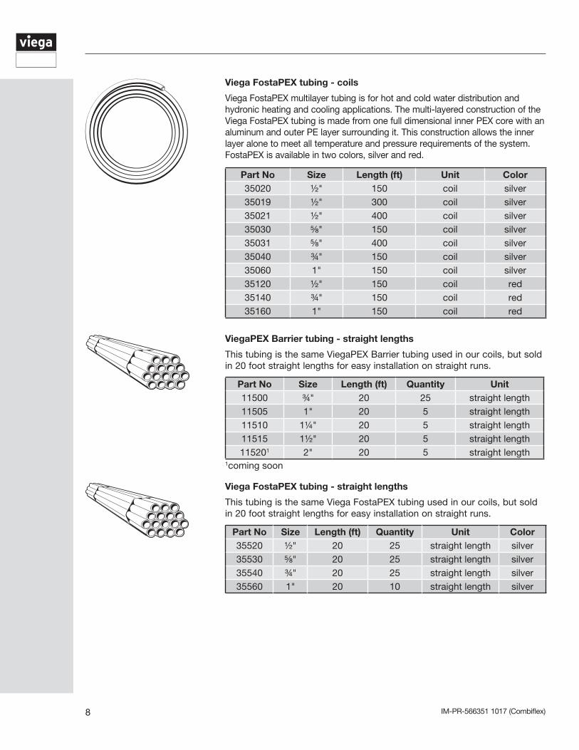
ViegaPEX Barrier tubing - coils
ViegaPEX Barrier, a cross-linked polyethylene (PEX) tubing, is for use in hydronic heating and cooling systems. ViegaPEX Barrier includes an oxygen barrier layer that helps restrict the passage of oxygen through the wall of the tubing.
Part No Size Length (ft) Unit11400 5/16" 250 coil11405 5/16" 1000 coil11410 5/16" 4000 coil11415 ⅜" 300 coil11418 ⅜" 1200 coil11420 ⅜" 2400 coil11428 ½" 250 coil11425 ½" 300 coil11430 ½" 400 coil11427 ½" 500 coil11436 ½" 1000 coil11435 ½" 1200 coil11440 ½" 2000 coil11445 ⅝" 500 coil11450 ⅝" 1500 coil11455 ¾" 150 coil11457 ¾" 300 coil11458 ¾" 500 coil11460 ¾" 800 coil11462 ¾" 1000 coil11465 1" 150 coil11470 1" 500 coil11475 1¼" 100 coil11480 1½" 100 coil114851 2" 100 coil
1coming soon
IM-PR-566351 1017 (Combiflex)8
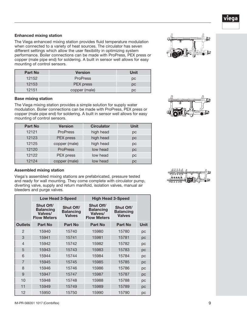
Viega FostaPEX tubing - straight lengths
This tubing is the same Viega FostaPEX tubing used in our coils, but sold in 20 foot straight lengths for easy installation on straight runs.
Part No Size Length (ft) Quantity Unit Color35520 ½" 20 25 straight length silver35530 ⅝" 20 25 straight length silver35540 ¾" 20 25 straight length silver35560 1" 20 10 straight length silver
ViegaPEX Barrier tubing - straight lengths
This tubing is the same ViegaPEX Barrier tubing used in our coils, but sold in 20 foot straight lengths for easy installation on straight runs.
Part No Size Length (ft) Quantity Unit11500 ¾" 20 25 straight length11505 1" 20 5 straight length11510 1¼" 20 5 straight length11515 1½" 20 5 straight length115201 2" 20 5 straight length
1coming soon
Viega FostaPEX tubing - coils
Viega FostaPEX multilayer tubing is for hot and cold water distribution and hydronic heating and cooling applications. The multi-layered construction of the Viega FostaPEX tubing is made from one full dimensional inner PEX core with an aluminum and outer PE layer surrounding it. This construction allows the inner layer alone to meet all temperature and pressure requirements of the system. FostaPEX is available in two colors, silver and red.
Part No Size Length (ft) Unit Color35020 ½" 150 coil silver35019 ½" 300 coil silver35021 ½" 400 coil silver35030 ⅝" 150 coil silver35031 ⅝" 400 coil silver35040 ¾" 150 coil silver35060 1" 150 coil silver35120 ½" 150 coil red35140 ¾" 150 coil red35160 1" 150 coil red
IM-PR-566351 1017 (Combiflex) 9
Assembled mixing station
Viega's assembled mixing stations are prefabricated, pressure tested and ready for wall mounting. They come complete with circulator pump, diverting valve, supply and return manifold, isolation valves, manual air bleeders and purge valves.
Low Head 3-Speed High Head 3-Speed
Shut Off/ Balancing
Valves/ Flow Meters
Shut Off/ Balancing
Valves
Shut Off/ Balancing
Valves/ Flow Meters
Shut Off/ Balancing
Valves
Outlets Part No Part No Part No Part No Unit
2 15940 15740 15980 15780 pc
3 15941 15741 15981 15781 pc
4 15942 15742 15982 15782 pc
5 15943 15743 15983 15783 pc
6 15944 15744 15984 15784 pc
7 15945 15745 15985 15785 pc
8 15946 15746 15986 15786 pc
9 15947 15747 15987 15787 pc
10 15948 15748 15988 15788 pc
11 15949 15749 15989 15789 pc
12 15950 15750 15990 15790 pc
Enhanced mixing station
The Viega enhanced mixing station provides fluid temperature modulation when connected to a variety of heat sources. The circulator has seven different settings which allow the user flexibility in optimizing system performance. Boiler connections can be made with ProPress, PEX press or copper (male pipe end) for soldering. A built in sensor well allows for easy mounting of control sensors.
Part No Version Unit12152 ProPress pc12153 PEX press pc12151 copper (male) pc
Base mixing station
The Viega mixing station provides a simple solution for supply water modulation. Boiler connections can be made with ProPress, PEX press or copper (male pipe end) for soldering. A built in sensor well allows for easy mounting of control sensors.
Part No Version Circulator Unit12121 ProPress high head pc12123 PEX press high head pc12125 copper (male) high head pc12120 ProPress low head pc12122 PEX press low head pc12124 copper (male) low head pc
IM-PR-566351 1017 (Combiflex)10
1¼" Stainless steel manifold
Viega 1¼" stainless steel manifolds come with 6⅝" spacing brackets for compact remote mounting. Stainless manifolds offer a choice of shutoff/balancing/ flow meter (SOBFM), shutoff/balancing (SOB) and valveless configurations depending on your project requirements.
Outlets Part No SOBFM Part No SOB Part No Valveless Unit2 15900 15700 16500 set3 15901 15701 16501 set4 15902 15702 16502 set5 15903 15703 16503 set6 15904 15704 16504 set7 15905 15705 16505 set8 15906 15706 16506 set9 15907 15707 16507 set
10 15908 15708 16508 set11 15909 15709 16509 set12 15910 15710 16510 set
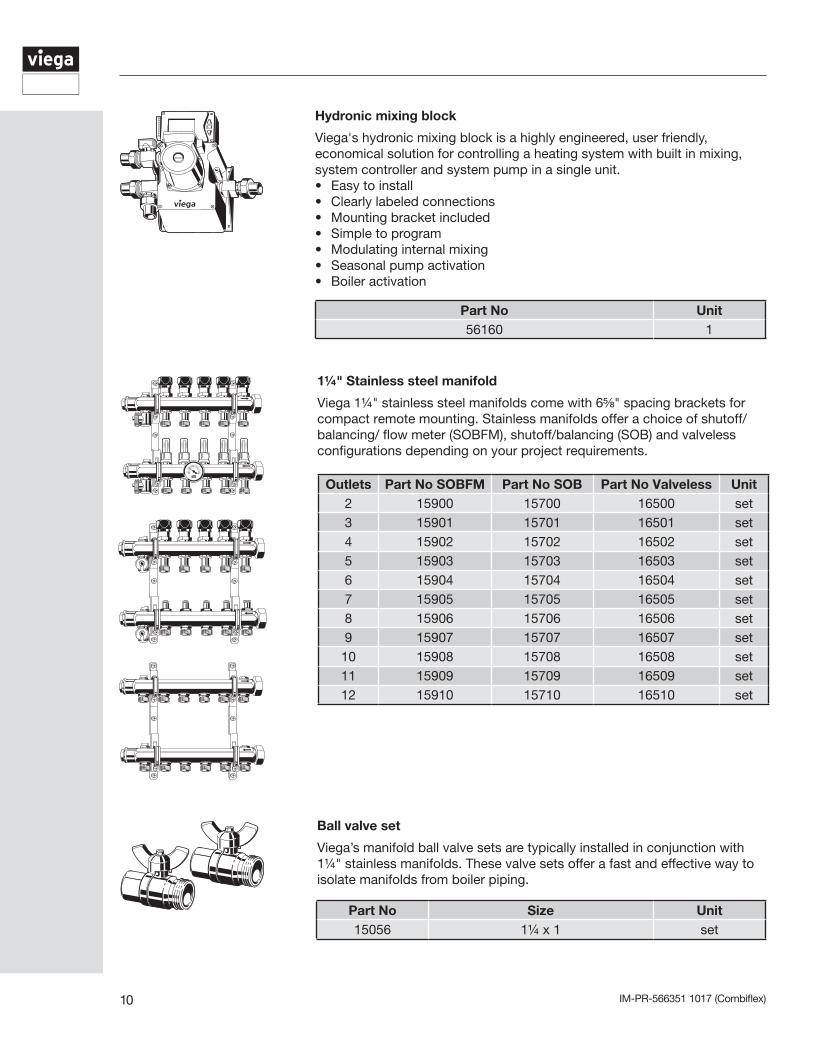
Hydronic mixing block
Viega's hydronic mixing block is a highly engineered, user friendly, economical solution for controlling a heating system with built in mixing, system controller and system pump in a single unit.• Easy to install • Clearly labeled connections• Mounting bracket included• Simple to program• Modulating internal mixing• Seasonal pump activation• Boiler activation
Part No Unit56160 1
Ball valve set
Viega’s manifold ball valve sets are typically installed in conjunction with 1¼" stainless manifolds. These valve sets offer a fast and effective way to isolate manifolds from boiler piping.
Part No Size Unit15056 1¼ x 1 set
IM-PR-566351 1017 (Combiflex) 11
SVC compression PEX adapters
These compression fittings attach PEX tubing to Viega manifolds or other SVC connections.
Part No Size Unit19007 5/16" 2/pkg19008 ⅜" 2/pkg19009 ½" 2/pkg19010 ⅝" 2/pkg19011 ¾" 2/pkg
SVC PEX press adapters
These adapters allow the Viega press connection system to be used on manifolds or other SVC connection components.
Part No Size Unit89407 5/16" 5/pkg89408 ⅜" 5/pkg89409 ½" 5/pkg89413 ⅝" 5/pkg89410 ¾" 5/pkg
Part No Size Unit16428 ¾" 1
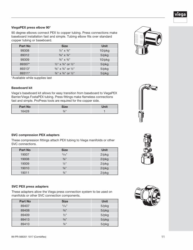
ViegaPEX press elbow 90°
90 degree elbows connect PEX to copper tubing. Press connections make baseboard installation fast and simple. Tubing elbow fits over standard copper tubing or baseboard.
Part No Size Unit99308 ½" x ¾" 10/pkg89312 ⅝" x ¾" 5/pkg99309 ¾" x ¾" 10/pkg89307* ½" x ¾" or ½" 5/pkg89313* ⅝" x ¾" or ½" 5/pkg89311* ¾" x ¾" or ½" 5/pkg
*Available while supplies last
Baseboard kit
Viega's baseboard kit allows for easy transition from baseboard to ViegaPEX Barrier/Viega FostaPEX tubing. Press fittings make flameless connections fast and simple. ProPress tools are required for the copper side.
IM-PR-566351 1017 (Combiflex)12
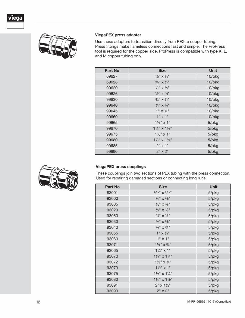
ViegaPEX press couplings
These couplings join two sections of PEX tubing with the press connection. Used for repairing damaged sections or connecting long runs.
Part No Size Unit83001 5/16" x 5/16" 5/pkg93000 ⅜" x ⅜" 5/pkg93005 ½" x ⅜" 5/pkg93020 ½" x ½" 5/pkg93050 ¾" x ½" 5/pkg83030 ⅝" x ⅝" 5/pkg93040 ¾" x ¾" 5/pkg93055 1" x ¾" 5/pkg93060 1" x 1" 5/pkg93071 1¼" x ¾" 5/pkg93065 1¼" x 1" 5/pkg93070 1¼" x 1¼" 5/pkg93072 1½" x ¾" 5/pkg93073 1½" x 1" 5/pkg93075 1½" x 1¼" 5/pkg93080 1½" x 1½" 5/pkg93091 2" x 1½" 5/pkg93090 2" x 2" 5/pkg
ViegaPEX press adapter
Use these adapters to transition directly from PEX to copper tubing. Press fittings make flameless connections fast and simple. The ProPress tool is required for the copper side. ProPress is compatible with type K, L, and M copper tubing only.
Part No Size Unit69627 ½" x ⅝" 10/pkg69628 ⅝" x ¾" 10/pkg99620 ½" x ½" 10/pkg99626 ½" x ¾" 10/pkg99630 ¾" x ½" 10/pkg99640 ¾" x ¾" 10/pkg99645 1" x ¾" 10/pkg99660 1" x 1" 10/pkg99665 1¼" x 1" 5/pkg99670 1¼" x 1¼" 5/pkg99675 1½" x 1" 5/pkg99680 1½" x 1½" 5/pkg99685 2" x 1" 5/pkg99690 2" x 2" 5/pkg
IM-PR-566351 1017 (Combiflex) 13
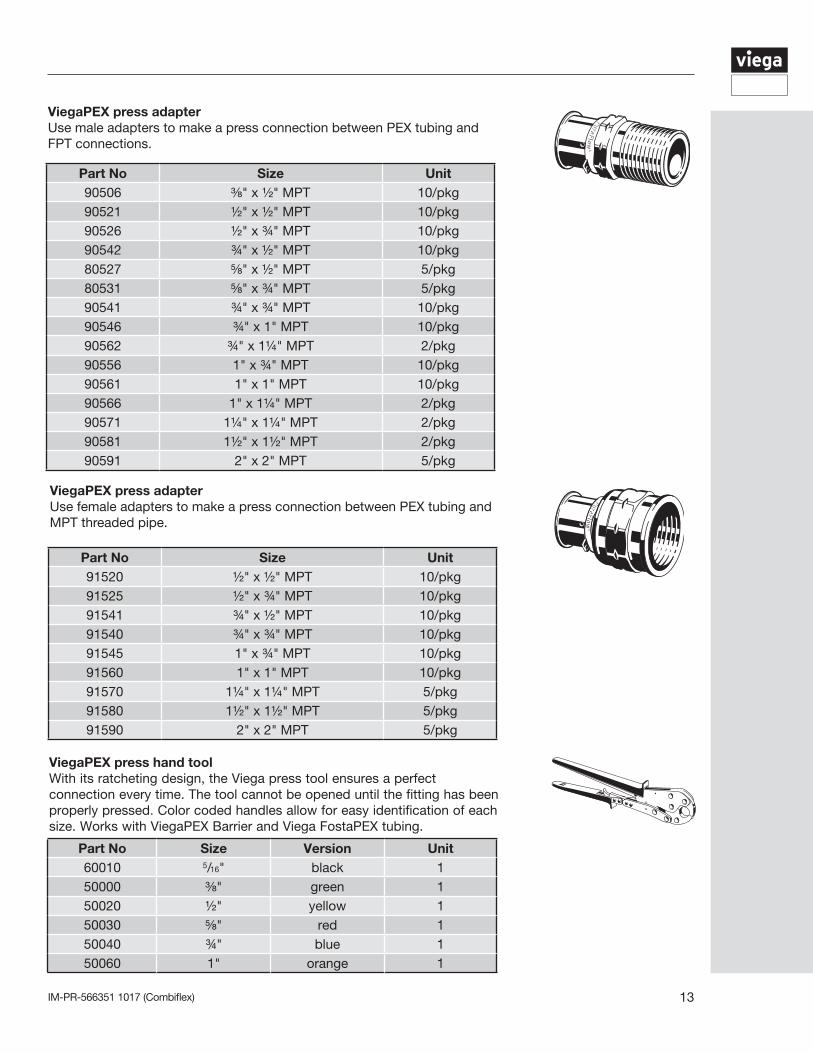
ViegaPEX press adapterUse male adapters to make a press connection between PEX tubing and FPT connections.
Part No Size Unit90506 ⅜" x ½" MPT 10/pkg90521 ½" x ½" MPT 10/pkg90526 ½" x ¾" MPT 10/pkg90542 ¾" x ½" MPT 10/pkg80527 ⅝" x ½" MPT 5/pkg80531 ⅝" x ¾" MPT 5/pkg90541 ¾" x ¾" MPT 10/pkg90546 ¾" x 1" MPT 10/pkg90562 ¾" x 1¼" MPT 2/pkg90556 1" x ¾" MPT 10/pkg90561 1" x 1" MPT 10/pkg90566 1" x 1¼" MPT 2/pkg90571 1¼" x 1¼" MPT 2/pkg90581 1½" x 1½" MPT 2/pkg90591 2" x 2" MPT 5/pkg
ViegaPEX press adapterUse female adapters to make a press connection between PEX tubing and MPT threaded pipe.
Part No Size Unit91520 ½" x ½" MPT 10/pkg91525 ½" x ¾" MPT 10/pkg91541 ¾" x ½" MPT 10/pkg91540 ¾" x ¾" MPT 10/pkg91545 1" x ¾" MPT 10/pkg91560 1" x 1" MPT 10/pkg91570 1¼" x 1¼" MPT 5/pkg91580 1½" x 1½" MPT 5/pkg91590 2" x 2" MPT 5/pkg
ViegaPEX press hand toolWith its ratcheting design, the Viega press tool ensures a perfect connection every time. The tool cannot be opened until the fitting has been properly pressed. Color coded handles allow for easy identification of each size. Works with ViegaPEX Barrier and Viega FostaPEX tubing.
Part No Size Version Unit60010 5/16" black 150000 ⅜" green 150020 ½" yellow 150030 ⅝" red 150040 ¾" blue 150060 1" orange 1
IM-PR-566351 1017 (Combiflex)14
PEX press complete heating tool set
This set is equipped with case, prep tool, and PEX press hand tool.
Part No Size Unit56030 ⅜", ½", ⅝", ¾", 1" 1
Viega FostaPEX prep tools
This tool peels the outer PE and aluminum layers from Viega FostaPEX tubing, allowing for the tube to be used with the standard press fitting system.
Part No Size Unit54030 ½", ¾" 154050 ⅝", 1" 1
Part No Size Unit15320 1" x 10' 1
Basic heating control
The basic heating control modulates system water temperature as outdoor temperature changes.
• Outdoor reset• Modulating mixing valve control • Supply temperature high limit• Seasonal pump activation• Boiler activation• Mixing valve and pump exercising
Part No Unit16015 1
item
Repair coupling wrapUsed for wrapping PEX press fittings in a slab.
Powerhead
Fits 1¼" stainless steel manifold return valves to provide individual zone control. 24 VAC, normally closed. Connects to standard Zone Control or can be wired directly with thermostats.
Part No V Wire Unit15061 24 VAC 2 115064 24 VAC 4 1
IM-PR-566351 1017 (Combiflex) 15
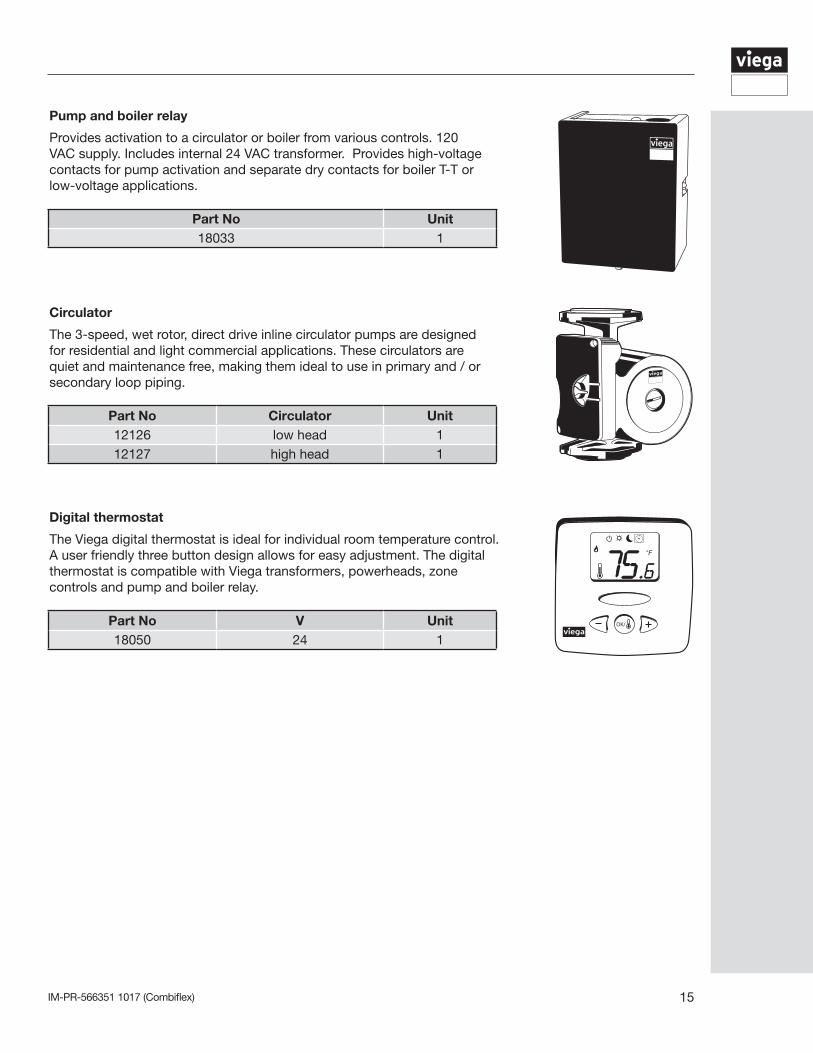
Pump and boiler relay
Provides activation to a circulator or boiler from various controls. 120 VAC supply. Includes internal 24 VAC transformer. Provides high-voltage contacts for pump activation and separate dry contacts for boiler T-T or low-voltage applications.
Part No Unit18033 1
Circulator
The 3-speed, wet rotor, direct drive inline circulator pumps are designed for residential and light commercial applications. These circulators are quiet and maintenance free, making them ideal to use in primary and / or secondary loop piping.
Part No Circulator Unit12126 low head 112127 high head 1
Digital thermostat
The Viega digital thermostat is ideal for individual room temperature control. A user friendly three button design allows for easy adjustment. The digital thermostat is compatible with Viega transformers, powerheads, zone controls and pump and boiler relay.
Part No V Unit18050 24 1
IM-PR-566351 1017 (Combiflex)16
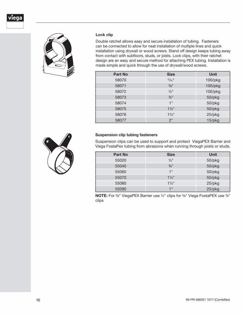
Lock clip
Double ratchet allows easy and secure installation of tubing. Fasteners can be connected to allow for neat installation of multiple lines and quick installation using drywall or wood screws. Stand off design keeps tubing away from contact with subfloors, studs, or joists. Lock clips, with their ratchet design are an easy and secure method for attaching PEX tubing. Installation is made simple and quick through the use of drywall/wood screws.
Part No Size Unit58070 5/16" 100/pkg58071 ⅜" 100/pkg58072 ½" 100/pkg58073 ¾" 50/pkg58074 1" 50/pkg58075 1¼" 50/pkg58076 1½" 25/pkg58077 2" 15/pkg
Suspension clip tubing fasteners
Suspension clips can be used to support and protect ViegaPEX Barrier and Viega FostaPex tubing from abrasions when running through joists or studs.
Part No Size Unit55020 ½" 50/pkg55040 ¾" 50/pkg55060 1" 50/pkg55070 1¼" 50/pkg55080 1½" 25/pkg55090 1" 25/pkg
NOTE: For ⅝" ViegaPEX Barrier use ½" clips for ⅝" Viega FostaPEX use ¾" clips
IM-PR-566351 1017 (Combiflex) 17
3 Combiflex System Design
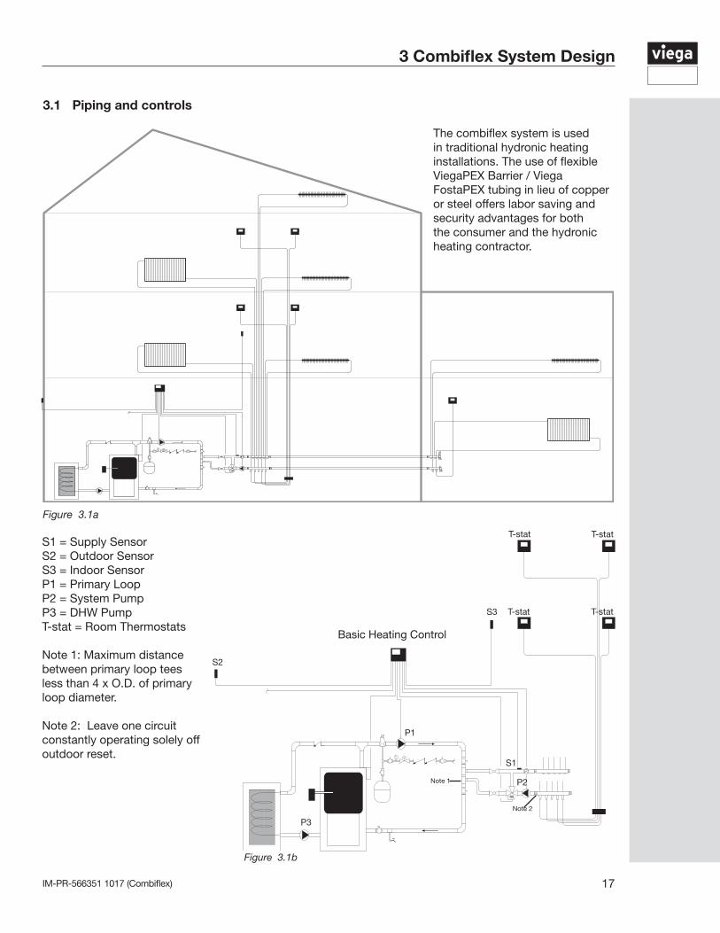
The combiflex system is used in traditional hydronic heating installations. The use of flexible ViegaPEX Barrier / Viega FostaPEX tubing in lieu of copper or steel offers labor saving and security advantages for both the consumer and the hydronic heating contractor.
3.1 Piping and controls
Figure 3.1a
Figure 3.1b
S2
S1
S3
P1
P2
P3
T-stat
Note 1
Note 2
Basic Heating Control
T-stat
T-stat T-stat
S1 = Supply SensorS2 = Outdoor SensorS3 = Indoor SensorP1 = Primary LoopP2 = System PumpP3 = DHW PumpT-stat = Room Thermostats
Note 1: Maximum distance between primary loop tees less than 4 x O.D. of primary loop diameter.
Note 2: Leave one circuit constantly operating solely off outdoor reset.
IM-PR-566351 1017 (Combiflex)18
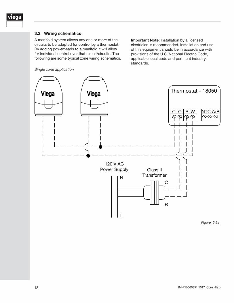
Important Note: Installation by a licensed electrician is recommended. Installation and use of this equipment should be in accordance with provisions of the U.S. National Electric Code, applicable local code and pertinent industry standards.
3.2 Wiring schematics
A manifold system allows any one or more of the circuits to be adapted for control by a thermostat. By adding powerheads to a manifold it will allow for individual control over that circuit/circuits. The following are some typical zone wiring schematics.
Figure 3.2a
Thermostat - 18050
C C R W NTC A/B
C
R
N
L
120 V ACPower Supply Class II
Transformer
Single zone application
IM-PR-566351 1017 (Combiflex) 19
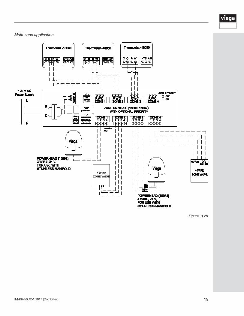
Multi-zone application
1111 2 2 2 2 3333 4 4 4 4
3 WIREZONE VALVE
Figure 3.2b
IM-PR-566351 1017 (Combiflex)20
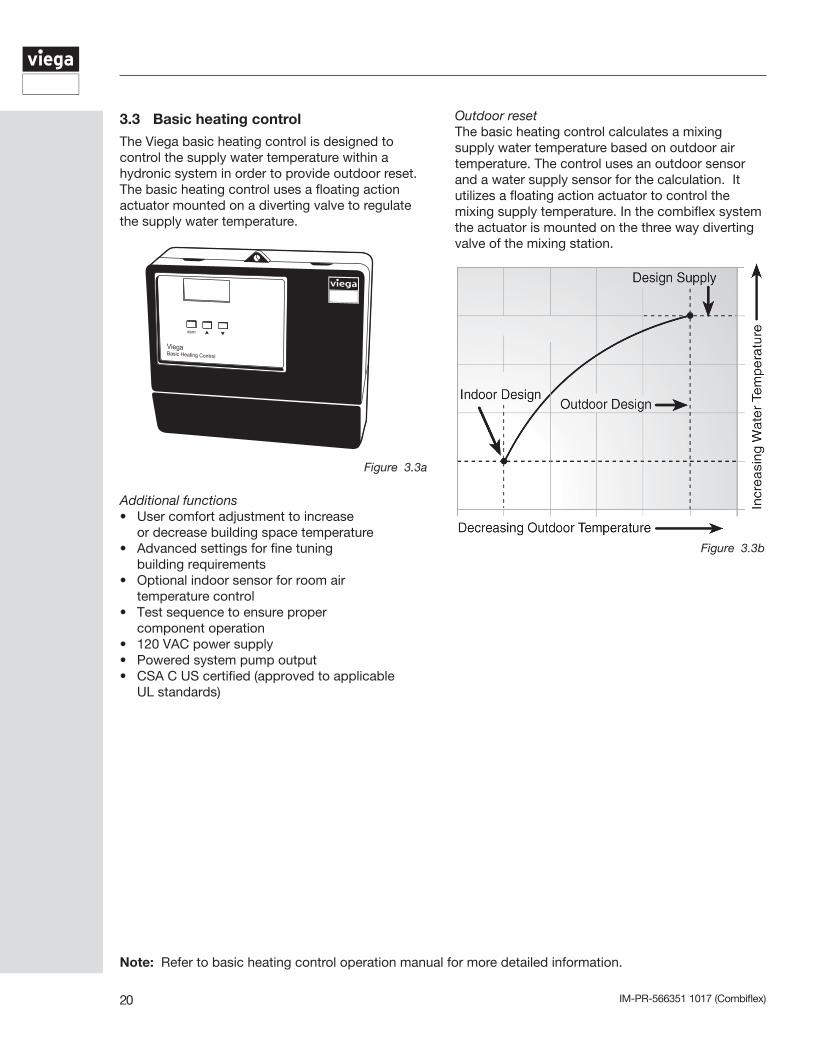
3.3 Basic heating control
The Viega basic heating control is designed to control the supply water temperature within a hydronic system in order to provide outdoor reset. The basic heating control uses a floating action actuator mounted on a diverting valve to regulate the supply water temperature.
Note: Refer to basic heating control operation manual for more detailed information.
Figure 3.3a
Figure 3.3b
item
Additional functions• User comfort adjustment to increase or decrease building space temperature• Advanced settings for fine tuning building requirements• Optional indoor sensor for room air temperature control• Test sequence to ensure proper component operation• 120 VAC power supply• Powered system pump output• CSA C US certified (approved to applicable UL standards)
Outdoor resetThe basic heating control calculates a mixing supply water temperature based on outdoor air temperature. The control uses an outdoor sensor and a water supply sensor for the calculation. It utilizes a floating action actuator to control the mixing supply temperature. In the combiflex system the actuator is mounted on the three way diverting valve of the mixing station.
IM-PR-566351 1017 (Combiflex) 21
Adjust menu display settings to change heat curve
To make an adjustment to a setting in the control, press and hold simultaneously for 1 second, the Item, and buttons. The display will then show the word ADJUST in the top right corner. Select the desired item using the Item button. Finally, use the and / or button to make the adjustment. See sections 3.2 and 3.3 (pages 6 and 7) of the basic heating control operation manual for further discussion on these items and their effect on control operation.
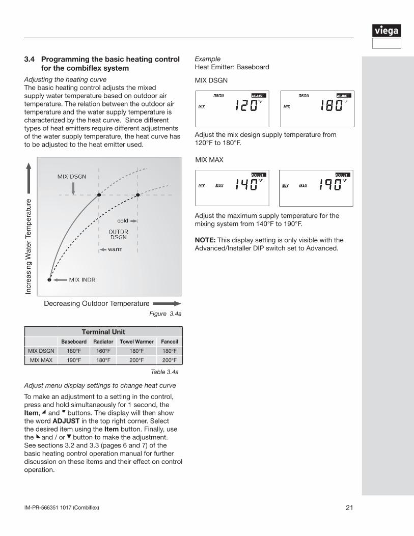
ExampleHeat Emitter: Baseboard
Adjust the mix design supply temperature from 120°F to 180°F.
MIX DSGN
MIX MAX
Adjust the maximum supply temperature for the mixing system from 140°F to 190°F.
NOTE: This display setting is only visible with theAdvanced/Installer DIP switch set to Advanced.
Figure 3.4a
Table 3.4a
3.4 Programming the basic heating control for the combiflex system
Adjusting the heating curveThe basic heating control adjusts the mixed supply water temperature based on outdoor air temperature. The relation between the outdoor air temperature and the water supply temperature is characterized by the heat curve. Since different types of heat emitters require different adjustments of the water supply temperature, the heat curve has to be adjusted to the heat emitter used.
Terminal UnitBaseboard Radiator Towel Warmer Fancoil
MIX DSGN 180°F 160°F 180°F 180°F
MIX MAX 190°F 180°F 200°F 200°F
IM-PR-566351 1017 (Combiflex)22
Setup menu
1. The SETUP MENU is used for entering the design values, as well as assigning different control options to the circulator and boiler. To access the SETUP MENU, push the middle rectangular button on the STATUS MENU. Use the up and down arrow keys to scroll through the various settings.
2. To select an item, align the cursor arrow with the item you wish to select and press the middle rectangular button . The arrow will become solid, which indicates that an item has been selected.
3. Once adjustment is complete, push the middle rectangular button. This will de-select the item.
4. To go to the previous screen, select BACK and press the middle rectangular button.
5. If the SETUP MENU is left idle for more than 90 seconds, the display will change to the STATUS MENU and the hydronic mixing block
will begin operating.
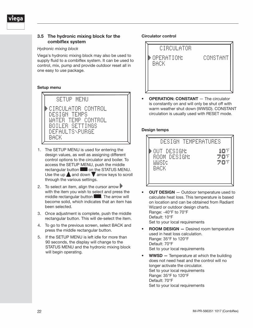
Circulator control
• OPERATION: CONSTANT — The circulator is constantly on and will only be shut off with warm weather shut down (WWSD). CONSTANT circulation is usually used with RESET mode.
Design temps
• OUT DESIGN — Outdoor temperature used to calculate heat loss. This temperature is based on location and can be obtained from Radiant Wizard or outdoor design charts.
Range: -40°F to 70°F Default: 10°F Set to your local requirements
• ROOM DESIGN — Desired room temperature used in heat loss calculation.
Range: 35°F to 120°F Default: 70°F Set to your local requirements
• WWSD — Temperature at which the building does not need heat and the control will no longer activate the circulator.
Set to your local requirements Range: 35°F to 120°F Default: 70°F Set to your local requirements
3.5 The hydronic mixing block for the combiflex system
Hydronic mixing block
Viega's hydronic mixing block may also be used to supply fluid to a combiflex system. It can be used to control, mix, pump and provide outdoor reset all in one easy to use package.
IM-PR-566351 1017 (Combiflex) 23
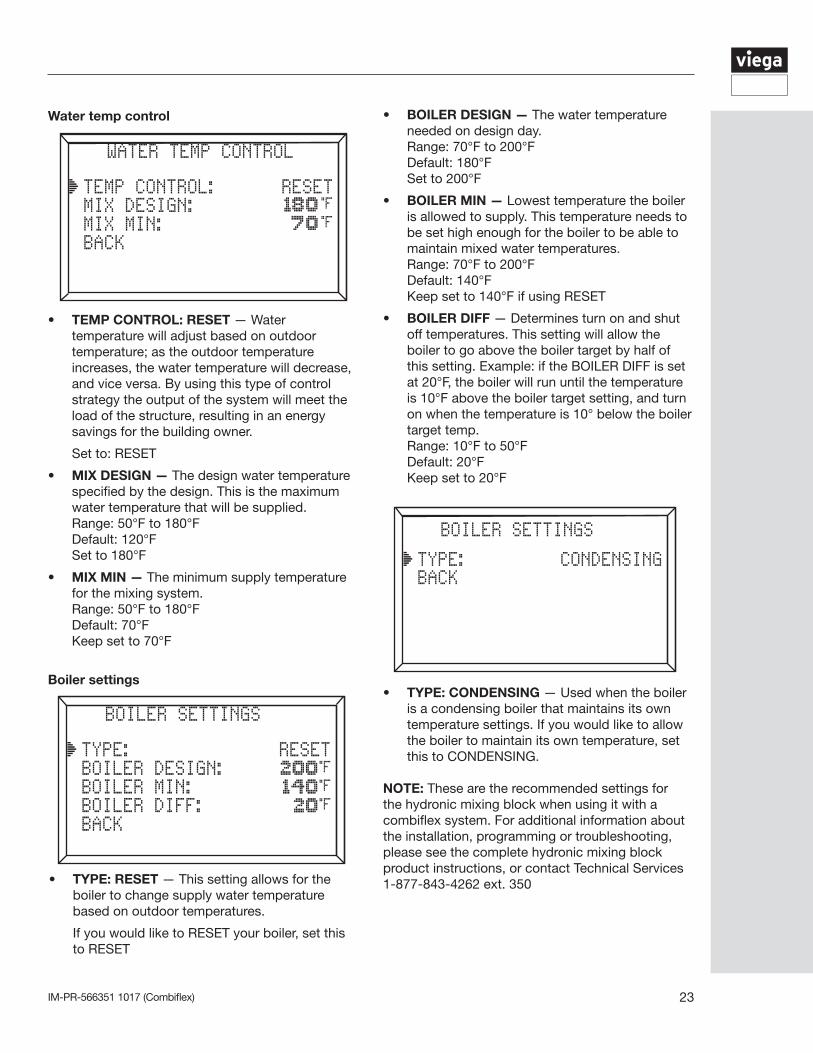
Water temp control
• TEMP CONTROL: RESET — Water temperature will adjust based on outdoor temperature; as the outdoor temperature increases, the water temperature will decrease, and vice versa. By using this type of control strategy the output of the system will meet the load of the structure, resulting in an energy savings for the building owner.
Set to: RESET
• MIX DESIGN — The design water temperature specified by the design. This is the maximum water temperature that will be supplied.
Range: 50°F to 180°F Default: 120°F Set to 180°F
• MIX MIN — The minimum supply temperature for the mixing system.
Range: 50°F to 180°F Default: 70°F Keep set to 70°F
Boiler settings
• TYPE: RESET — This setting allows for the boiler to change supply water temperature based on outdoor temperatures.
If you would like to RESET your boiler, set this to RESET
• BOILER DESIGN — The water temperature needed on design day.
Range: 70°F to 200°F Default: 180°F Set to 200°F
• BOILER MIN — Lowest temperature the boiler is allowed to supply. This temperature needs to be set high enough for the boiler to be able to maintain mixed water temperatures.
Range: 70°F to 200°F Default: 140°F Keep set to 140°F if using RESET
• BOILER DIFF — Determines turn on and shut off temperatures. This setting will allow the boiler to go above the boiler target by half of this setting. Example: if the BOILER DIFF is set at 20°F, the boiler will run until the temperature is 10°F above the boiler target setting, and turn on when the temperature is 10° below the boiler target temp.
Range: 10°F to 50°F Default: 20°F Keep set to 20°F
• TYPE: CONDENSING — Used when the boiler is a condensing boiler that maintains its own temperature settings. If you would like to allow the boiler to maintain its own temperature, set this to CONDENSING.
NOTE: These are the recommended settings for the hydronic mixing block when using it with a combiflex system. For additional information about the installation, programming or troubleshooting, please see the complete hydronic mixing block product instructions, or contact Technical Services 1-877-843-4262 ext. 350
IM-PR-566351 1017 (Combiflex)24
Total Tubing Length (ft)
Btu/hFlow Rate
(gpm)
Total Feet of Baseboard
(Pressure drop, ft of hd)50 100 150 200 250 300 350 400
10000 118
(0.07)
Low
(0.8)
Low
(1.6)
Low
(2.4)
Low
(3.2)
Low
(4.0)
Low
(4.9)
Low
(5.7)
Low
(6.5)
20000 236
(0.47)
Low
(2.7)
Low
(5.5)
Low
(8.2)
Low
(11.0)
High
(13.8)
High
(16.5)
High
(19.2)
High
(22.0)
30000 354
(1.44)
Low
(5.6)
Low
(11.2)
High
(16.8)
High
(22.4)
40000 472
(3.15)
Low
(9.3)
High
(18.6)
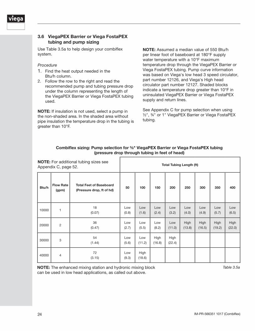
Combiflex sizing: Pump selection for ⅝" ViegaPEX Barrier or Viega FostaPEX tubing(pressure drop through tubing in feet of head)
Table 3.5a
3.6 ViegaPEX Barrier or Viega FostaPEX tubing and pump sizing
Use Table 3.5a to help design your combiflex
system.
Procedure1. Find the heat output needed in the Btu/h column.2. Follow the row to the right and read the
recommended pump and tubing pressure drop under the column representing the length of the ViegaPEX Barrier or Viega FostaPEX tubing used.
NOTE: If insulation is not used, select a pump in the non-shaded area. In the shaded area without pipe insulation the temperature drop in the tubing is greater than 10°F.
NOTE: Assumed a median value of 550 Btu/h per linear foot of baseboard at 180°F supply water temperature with a 10°F maximum temperature drop through the ViegaPEX Barrier or Viega FostaPEX tubing. Pump curve information was based on Viega's low head 3 speed circulator, part number 12126, and Viega's High head circulator part number 12127. Shaded blocks indicate a temperature drop greater than 10°F in uninsulated ViegaPEX Barrier or Viega FostaPEX supply and return lines.
See Appendix C for pump selection when using ½", ¾" or 1" ViegaPEX Barrier or Viega FostaPEX tubing.
NOTE: The enhanced mixing station and hydronic mixing block can be used in low head applications, as called out above.
NOTE: For additional tubing sizes see Appendix C, page 52.
IM-PR-566351 1017 (Combiflex) 25
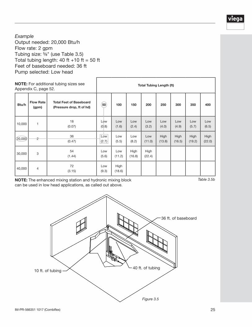
ExampleOutput needed: 20,000 Btu/hFlow rate: 2 gpm Tubing size: ⅝" (use Table 3.5)Total tubing length: 40 ft +10 ft = 50 ftFeet of baseboard needed: 36 ftPump selected: Low head
40 ft. of tubing10 ft. of tubing
36 ft. of baseboard
Table 3.5b
Figure 3.5
Total Tubing Length (ft)
Btu/hFlow Rate
(gpm)
Total Feet of Baseboard
(Pressure drop, ft of hd)50 100 150 200 250 300 350 400
10,000 118
(0.07)
Low
(0.8)
Low
(1.6)
Low
(2.4)
Low
(3.2)
Low
(4.0)
Low
(4.9)
Low
(5.7)
Low
(6.5)
20,000 236
(0.47)
Low
(2.7)
Low
(5.5)
Low
(8.2)
Low
(11.0)
High
(13.8)
High
(16.5)
High
(19.2)
High
(22.0)
30,000 354
(1.44)
Low
(5.6)
Low
(11.2)
High
(16.8)
High
(22.4)
40,000 472
(3.15)
Low
(9.3)
High
(18.6)
NOTE: The enhanced mixing station and hydronic mixing block can be used in low head applications, as called out above.
NOTE: For additional tubing sizes see Appendix C, page 52.
IM-PR-566351 1017 (Combiflex)26
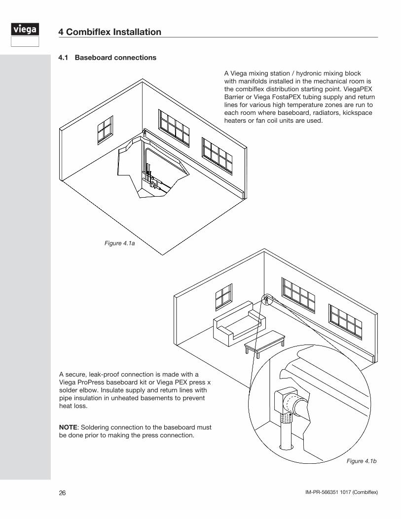
A Viega mixing station / hydronic mixing block with manifolds installed in the mechanical room is the combiflex distribution starting point. ViegaPEX Barrier or Viega FostaPEX tubing supply and return lines for various high temperature zones are run to each room where baseboard, radiators, kickspace heaters or fan coil units are used.
4.1 Baseboard connections
Figure 4.1a
4 Combiflex Installation
Figure 4.1b
A secure, leak-proof connection is made with a Viega ProPress baseboard kit or Viega PEX press x solder elbow. Insulate supply and return lines with pipe insulation in unheated basements to prevent heat loss.
NOTE: Soldering connection to the baseboard must be done prior to making the press connection.
IM-PR-566351 1017 (Combiflex) 27
4.2 Handling PEX tubing
The properties of PEX tubing make it very easy to work with. Some care must be taken to prevent damage to the tubing before and during installation:
• Do not store PEX tubing outdoors where it may be exposed to UV light.• ViegaPEX Barrier tubing has a 6 month UV rating.• Use care to protect PEX tubing from physical damage during storage and installation. Keep the tubing away from sharp objects, open flames, etc., and do not place heavy objects on the tubing.• Damaged sections of tubing should be cut out and discarded.• Viega FostaPEX, with its aluminum layer, is
resistant to UV light, but long term exposure should still be avoided.
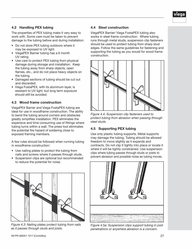
4.3 Wood frame construction
ViegaPEX Barrier and Viega FostaPEX tubing are ideal for use in woodframe construction. The ability to bend the tubing around corners and obstacles greatly simplifies installation. PEX eliminates the expensive and time consuming use of fittings where tubing turns within a wall. The press tool eliminates the potential fire hazard of soldering close to exposed framing members.
A few rules should be followed when running tubing in woodframe construction:
• Use nailing plates to protect the tubing from nails and screws where it passes through studs.• Suspension clips are optional but recommended to reduce the potential for noise.
4.5 Supporting PEX tubing
Use only plastic tubing supports. Metal supports may damage the tubing. Tubing should be allowed freedom to move slightly as it expands and contracts. Do not clip it tightly into place or locate it where it will be tightly constrained. Use suspension clips where tubing passes through studs or joists to prevent abrasion and possible noise as tubing moves.
Figure 4.3: Nailing plates protect tubing from nails as it passes through studs and joists.
4.4 Steel construction
ViegaPEX Barrier/ Viega FostaPEX tubing also works in steel frame construction. Where tubing runs through metal studs, suspension clip fasteners should be used to protect tubing from sharp stud edges. Follow the same guidelines for fastening and supporting the tubing as you would for wood frame construction.
Figure 4.5a: Suspension clips support tubing in joist penetrations or anywhere abrasion is a concern.
Figure 4.4: Suspension clip fasteners used to protect tubing from abrasion when passing through steel studs.
IM-PR-566351 1017 (Combiflex)28
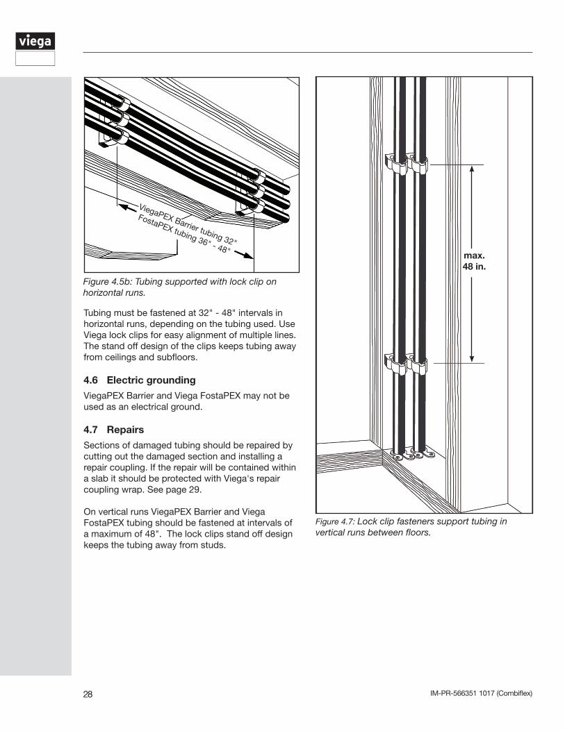
Figure 4.7: Lock clip fasteners support tubing in vertical runs between floors.
Figure 4.5b: Tubing supported with lock clip on horizontal runs.
Tubing must be fastened at 32" - 48" intervals in horizontal runs, depending on the tubing used. Use Viega lock clips for easy alignment of multiple lines. The stand off design of the clips keeps tubing away from ceilings and subfloors.
4.6 Electric grounding
ViegaPEX Barrier and Viega FostaPEX may not be used as an electrical ground.
4.7 Repairs
Sections of damaged tubing should be repaired by cutting out the damaged section and installing a repair coupling. If the repair will be contained within a slab it should be protected with Viega's repair coupling wrap. See page 29.
On vertical runs ViegaPEX Barrier and Viega FostaPEX tubing should be fastened at intervals of a maximum of 48". The lock clips stand off design keeps the tubing away from studs.
max. 48 in.
ViegaPEX Barrier tubing 32"
FostaPEX tubing 36" - 48"
IM-PR-566351 1017 (Combiflex) 29
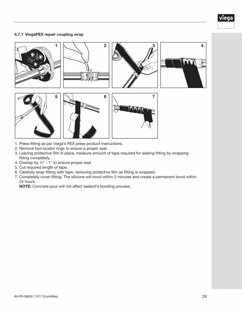
4.7.1 ViegaPEX repair coupling wrap
1 2 3 4
5 6 7
1. Press fitting as per Viega’s PEX press product instructions. 2. Remove tool locator rings to ensure a proper seal. 3. Leaving protective film in place, measure amount of tape required for sealing fitting by wrapping fitting completely. 4. Overlap by ½" - 1" to ensure proper seal5. Cut required length of tape.6. Carefully wrap fitting with tape, removing protective film as fitting is wrapped. 7. Completely cover fitting. The silicone will bond within 2 minutes and create a permanent bond within 24 hours. NOTE: Concrete pour will not affect sealant’s bonding process.
IM-PR-566351 1017 (Combiflex)30
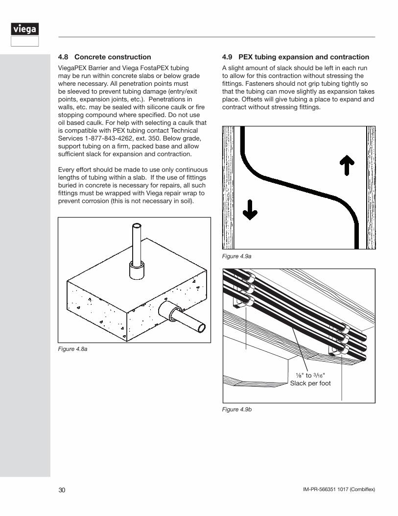
4.8 Concrete construction
ViegaPEX Barrier and Viega FostaPEX tubing may be run within concrete slabs or below grade where necessary. All penetration points must be sleeved to prevent tubing damage (entry/exit points, expansion joints, etc.). Penetrations in walls, etc. may be sealed with silicone caulk or fire stopping compound where specified. Do not use oil based caulk. For help with selecting a caulk that is compatible with PEX tubing contact Technical Services 1-877-843-4262, ext. 350. Below grade, support tubing on a firm, packed base and allow sufficient slack for expansion and contraction.
Every effort should be made to use only continuous lengths of tubing within a slab. If the use of fittings buried in concrete is necessary for repairs, all such fittings must be wrapped with Viega repair wrap to prevent corrosion (this is not necessary in soil).
Figure 4.8a
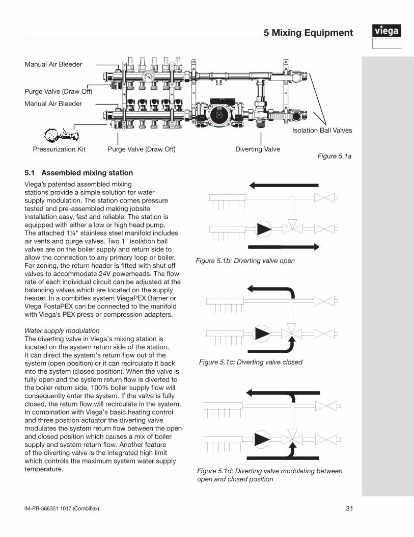
4.9 PEX tubing expansion and contraction
A slight amount of slack should be left in each run to allow for this contraction without stressing the fittings. Fasteners should not grip tubing tightly so that the tubing can move slightly as expansion takes place. Offsets will give tubing a place to expand and contract without stressing fittings.
Figure 4.9a
Figure 4.9b
⅛" to 3/16"Slack per foot
IM-PR-566351 1017 (Combiflex) 31
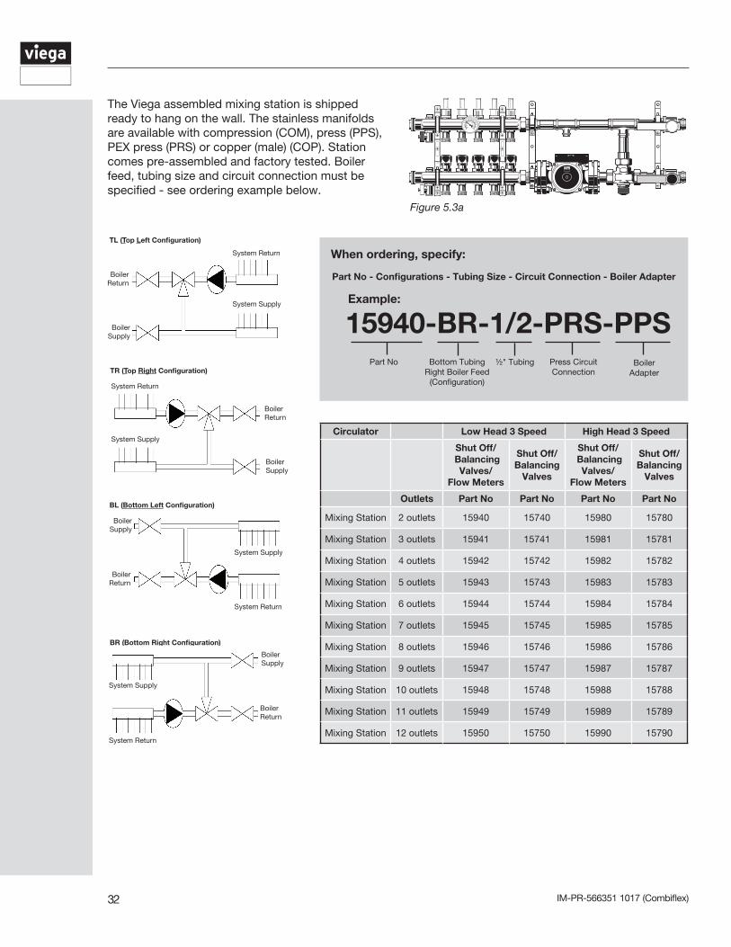
5.1 Assembled mixing station
Viega’s patented assembled mixing stations provide a simple solution for water supply modulation. The station comes pressure tested and pre-assembled making jobsite installation easy, fast and reliable. The station is equipped with either a low or high head pump. The attached 1¼" stainless steel manifold includes air vents and purge valves. Two 1" isolation ball valves are on the boiler supply and return side to allow the connection to any primary loop or boiler. For zoning, the return header is fitted with shut off valves to accommodate 24V powerheads. The flow rate of each individual circuit can be adjusted at the balancing valves which are located on the supply header. In a combiflex system ViegaPEX Barrier or Viega FostaPEX can be connected to the manifold with Viega’s PEX press or compression adapters. Water supply modulationThe diverting valve in Viega’s mixing station is located on the system return side of the station. It can direct the system's return flow out of the system (open position) or it can recirculate it back into the system (closed position). When the valve is fully open and the system return flow is diverted to the boiler return side, 100% boiler supply flow will consequently enter the system. If the valve is fully closed, the return flow will recirculate in the system. In combination with Viega’s basic heating control and three position actuator the diverting valve modulates the system return flow between the open and closed position which causes a mix of boiler supply and system return flow. Another feature of the diverting valve is the integrated high limit which controls the maximum system water supply temperature.
Figure 5.1b: Diverting valve open
Figure 5.1d: Diverting valve modulating between open and closed position
Figure 5.1c: Diverting valve closed
5 Mixing Equipment
Isolation Ball Valves
Diverting ValvePressurization Kit Purge Valve (Draw Off)
Purge Valve (Draw Off)
Manual Air Bleeder
Manual Air Bleeder
Figure 5.1a
IM-PR-566351 1017 (Combiflex)32
Figure 5.3a
The Viega assembled mixing station is shipped ready to hang on the wall. The stainless manifolds are available with compression (COM), press (PPS), PEX press (PRS) or copper (male) (COP). Station comes pre-assembled and factory tested. Boiler feed, tubing size and circuit connection must be specified - see ordering example below.
15940-BR-1/2-PRS-PPS
When ordering, specify:
Part No - Configurations - Tubing Size - Circuit Connection - Boiler Adapter
Example:
Part No Bottom TubingRight Boiler Feed
(Configuration)
½" Tubing Press Circuit Connection
Boiler Adapter
Circulator Low Head 3 Speed High Head 3 Speed
Shut Off/ Balancing
Valves/ Flow Meters
Shut Off/ Balancing
Valves
Shut Off/ Balancing
Valves/ Flow Meters
Shut Off/Balancing
Valves
Outlets Part No Part No Part No Part No
Mixing Station 2 outlets 15940 15740 15980 15780
Mixing Station 3 outlets 15941 15741 15981 15781
Mixing Station 4 outlets 15942 15742 15982 15782
Mixing Station 5 outlets 15943 15743 15983 15783
Mixing Station 6 outlets 15944 15744 15984 15784
Mixing Station 7 outlets 15945 15745 15985 15785
Mixing Station 8 outlets 15946 15746 15986 15786
Mixing Station 9 outlets 15947 15747 15987 15787
Mixing Station 10 outlets 15948 15748 15988 15788
Mixing Station 11 outlets 15949 15749 15989 15789
Mixing Station 12 outlets 15950 15750 15990 15790
TL (Top Left Configuration)
Boiler Return
Boiler Supply
System Return
System Supply
BL (Bottom Left Configuration)
Boiler Return
Boiler Supply
System Return
System Supply
TR (Top Right Configuration)
System Return
System Supply
Boiler Return
Boiler Supply
BR (Bottom Right Configuration)
Boiler Return
Boiler Supply
System Supply
System Return
IM-PR-566351 1017 (Combiflex) 33
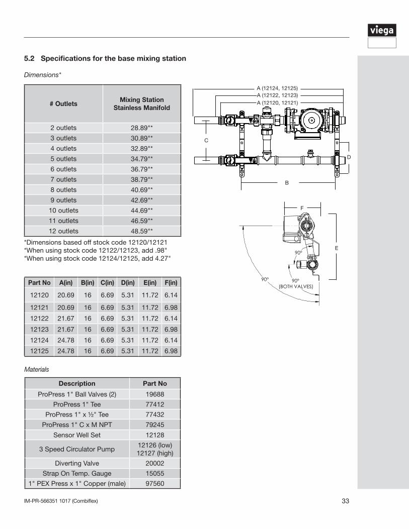
5.2 Specifications for the base mixing station
# OutletsMixing Station
Stainless Manifold
2 outlets 28.89"*
3 outlets 30.89"*
4 outlets 32.89"*
5 outlets 34.79"*
6 outlets 36.79"*
7 outlets 38.79"*
8 outlets 40.69"*
9 outlets 42.69"*
10 outlets 44.69"*
11 outlets 46.59"*
12 outlets 48.59"*
*Dimensions based off stock code 12120/12121*When using stock code 12122/12123, add .98"*When using stock code 12124/12125, add 4.27"
Dimensions*
Part No A(in) B(in) C(in) D(in) E(in) F(in)
12120 20.69 16 6.69 5.31 11.72 6.14
12121 20.69 16 6.69 5.31 11.72 6.98
12122 21.67 16 6.69 5.31 11.72 6.14
12123 21.67 16 6.69 5.31 11.72 6.98
12124 24.78 16 6.69 5.31 11.72 6.14
12125 24.78 16 6.69 5.31 11.72 6.98
90°(BOTH VALVES)
90°
90°
A (12124, 12125)A (12122, 12123)A (12120, 12121)
D
C
B
E
F
Materials
Description Part No
ProPress 1" Ball Valves (2) 19688
ProPress 1" Tee 77412
ProPress 1" x ½" Tee 77432
ProPress 1" C x M NPT 79245
Sensor Well Set 12128
3 Speed Circulator Pump12126 (low) 12127 (high)
Diverting Valve 20002
Strap On Temp. Gauge 15055
1" PEX Press x 1" Copper (male) 97560
IM-PR-566351 1017 (Combiflex)34
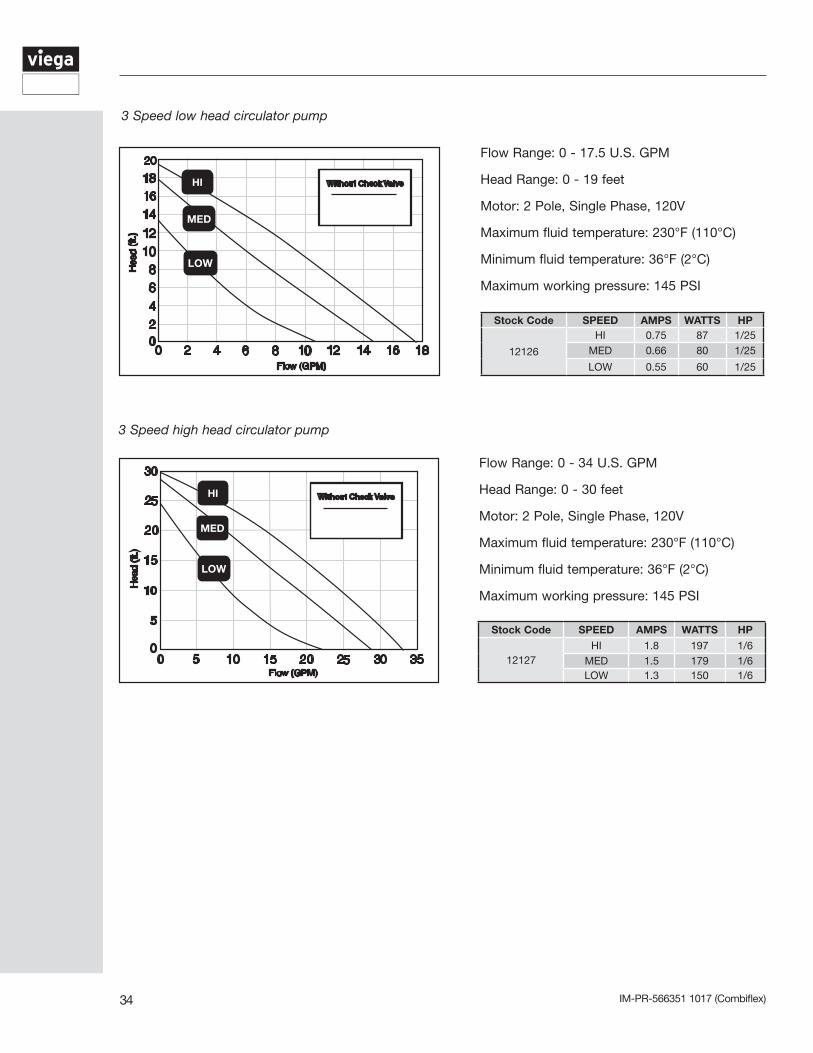
Stock Code SPEED AMPS WATTS HP
12126
HI 0.75 87 1/25MED 0.66 80 1/25
LOW 0.55 60 1/25
Flow Range: 0 - 17.5 U.S. GPM
Head Range: 0 - 19 feet
Motor: 2 Pole, Single Phase, 120V
Maximum fluid temperature: 230°F (110°C)
Minimum fluid temperature: 36°F (2°C)
Maximum working pressure: 145 PSI
Stock Code SPEED AMPS WATTS HP
12127HI 1.8 197 1/6
MED 1.5 179 1/6LOW 1.3 150 1/6
Flow Range: 0 - 34 U.S. GPM
Head Range: 0 - 30 feet
Motor: 2 Pole, Single Phase, 120V
Maximum fluid temperature: 230°F (110°C)
Minimum fluid temperature: 36°F (2°C)
Maximum working pressure: 145 PSI
3 Speed low head circulator pump
3 Speed high head circulator pump
IM-PR-566351 1017 (Combiflex) 35
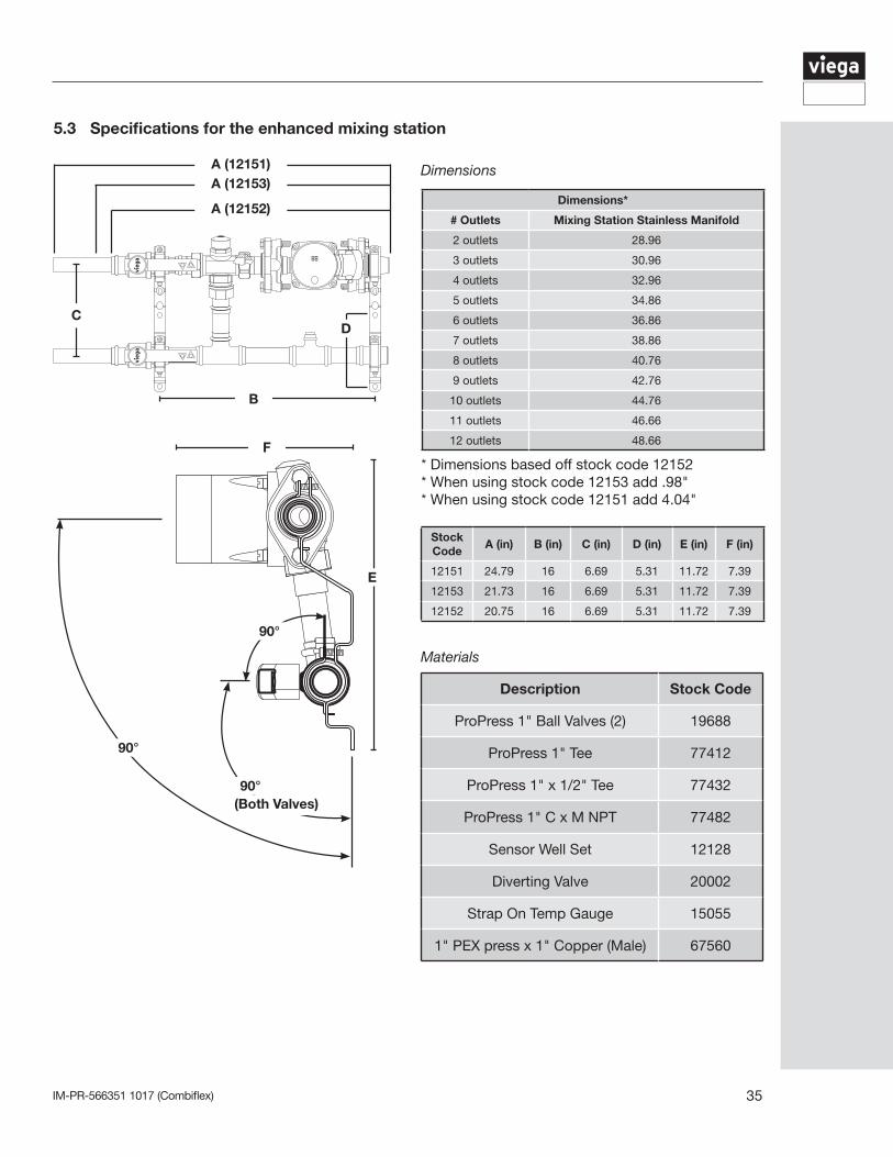
Dimensions*
# Outlets Mixing Station Stainless Manifold
2 outlets 28.96
3 outlets 30.96
4 outlets 32.96
5 outlets 34.86
6 outlets 36.86
7 outlets 38.86
8 outlets 40.76
9 outlets 42.76
10 outlets 44.76
11 outlets 46.66
12 outlets 48.66
* Dimensions based off stock code 12152* When using stock code 12153 add .98"* When using stock code 12151 add 4.04"
B
CD
A (12151)A (12153)
A (12152)
F
E
90°
90°
90°
(Both Valves)
Stock Code
A (in) B (in) C (in) D (in) E (in) F (in)
12151 24.79 16 6.69 5.31 11.72 7.39
12153 21.73 16 6.69 5.31 11.72 7.39
12152 20.75 16 6.69 5.31 11.72 7.39
Description Stock Code
ProPress 1" Ball Valves (2) 19688
ProPress 1" Tee 77412
ProPress 1" x 1/2" Tee 77432
ProPress 1" C x M NPT 77482
Sensor Well Set 12128
Diverting Valve 20002
Strap On Temp Gauge 15055
1" PEX press x 1" Copper (Male) 67560
5.3 Specifications for the enhanced mixing station
Dimensions
Materials
IM-PR-566351 1017 (Combiflex)36
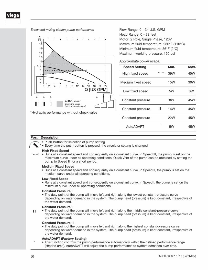
AUTO ADAPTOperating range(maximum - minimum)
*Hydraulic performance without check valve
Pos. Description
III
II
I
ADAPT
• Push-button for selection of pump setting• Every time the push-button is pressed, the circulator setting is changed
High Fixed Speed• Runs at a constant speed and consequently on a constant curve. In Speed III, the pump is set on the maximum curve under all operating conditions. Quick Vent of the pump can be obtained by setting the pump to Speed III for a short period.
Medium Fixed Speed• Runs at a constant speed and consequently on a constant curve. In Speed II, the pump is set on the medium curve under all operating conditions.
Low Fixed Speed• Runs at a constant speed and consequently on a constant curve. In Speed I, the pump is set on the minimum curve under all operating conditions.
Constant Pressure I• The duty point of the pump will move left and right along the lowest constant-pressure curve depending on water demand in the system. The pump head (pressure) is kept constant, irrespective of the water demand.
Constant Pressure II• The duty point of the pump will move left and right along the middle constant-pressure curve depending on water demand in the system. The pump head (pressure) is kept constant, irrespective of the water demand.
Constant Pressure III• The duty point of the pump will move left and right along the highest constant-pressure curve depending on water demand in the system. The pump head (pressure) is kept constant, irrespective of the water demand.
AutoADAPT (Factory Setting)• This function controls the pump performance automatically within the defined performance range (shaded area). AutoADAPT will adjust the pump performance to system demands over time.
III
II
I
ADAPT
III
II
I
ADAPT
III
II
I
ADAPT
III
II
I
ADAPT
III
II
I
ADAPT
III
II
I
ADAPT
III
II
I
ADAPT
Enhanced mixing station pump performance
Approximate power usage:
High fixed speed 39W 45W
Medium fixed speed 15W 30W
Low fixed speed 5W 8W
Constant pressure 8W 45W
Constant pressure 14W 45W
Constant pressure 22W 45W
AutoADAPT 5W 45W
Speed Setting Min. Max.
III
II
I
ADAPT
III
II
I
ADAPT
III
II
I
ADAPT
III
II
I
ADAPT
III
II
I
ADAPT
III
II
I
ADAPT
III
II
I
ADAPT
Flow Range: 0 - 34 U.S. GPMHead Range: 0 - 22 feetMotor: 2 Pole, Single Phase, 120VMaximum fluid temperature: 230°F (110°C)Minimum fluid temperature: 36°F (2°C)Maximum working pressure: 150 psi
IM-PR-566351 1017 (Combiflex) 37
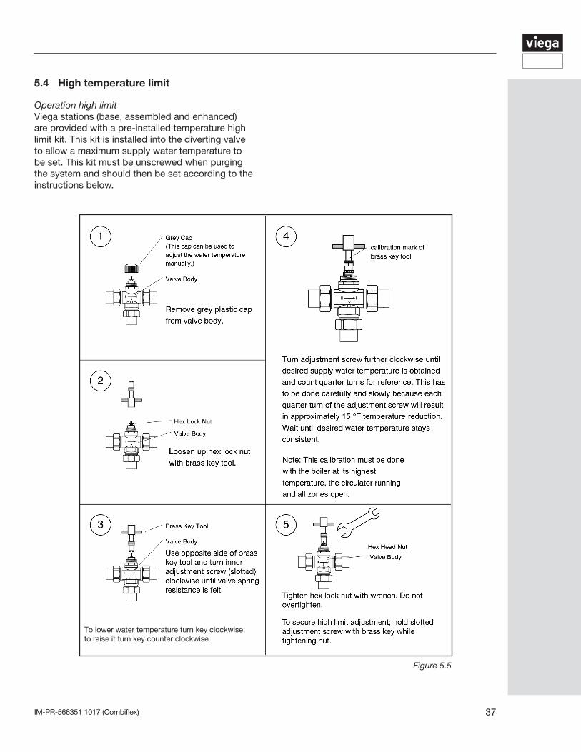
Operation high limitViega stations (base, assembled and enhanced) are provided with a pre-installed temperature high limit kit. This kit is installed into the diverting valve to allow a maximum supply water temperature to be set. This kit must be unscrewed when purging the system and should then be set according to the instructions below.
5.4 High temperature limit
Figure 5.5
To lower water temperature turn key clockwise; to raise it turn key counter clockwise.
IM-PR-566351 1017 (Combiflex)38
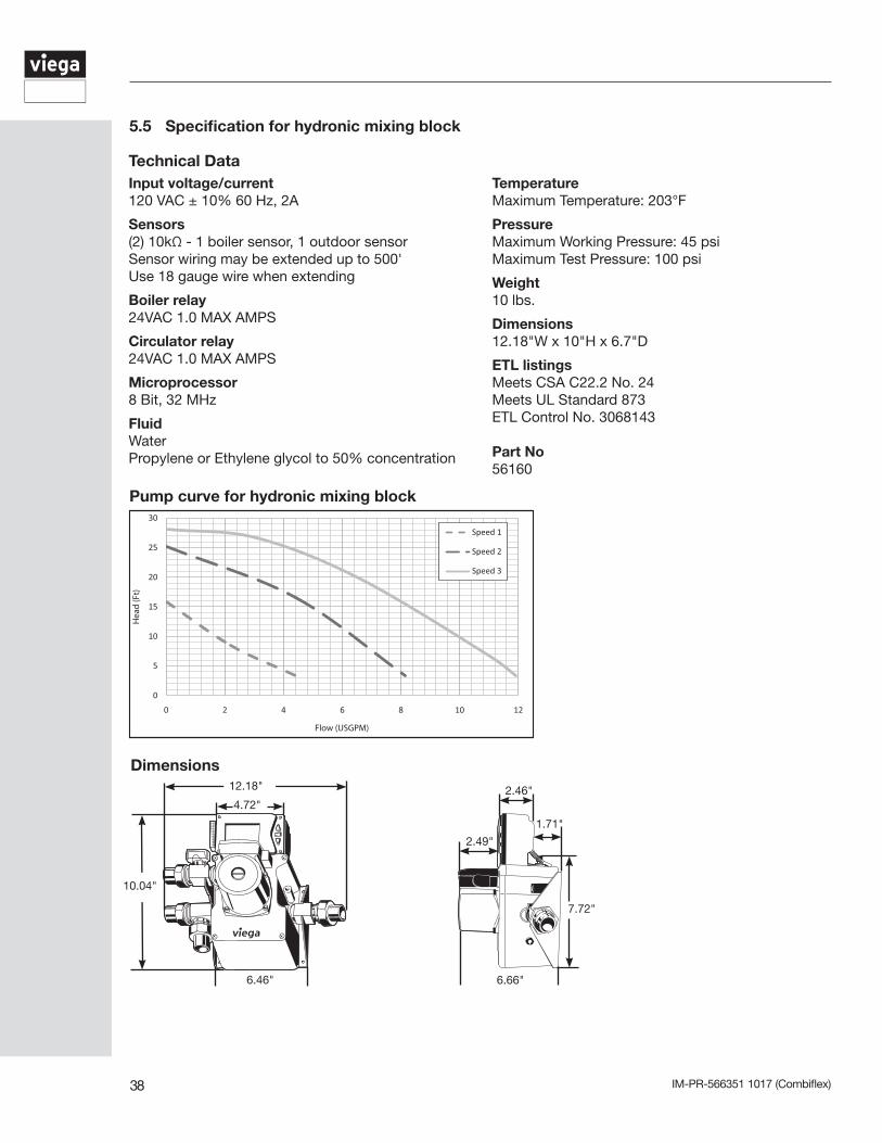
5.5 Specification for hydronic mixing block
Technical DataInput voltage/current120 VAC ± 10% 60 Hz, 2A
Sensors(2) 10kΩ - 1 boiler sensor, 1 outdoor sensorSensor wiring may be extended up to 500'Use 18 gauge wire when extending
Boiler relay24VAC 1.0 MAX AMPS
Circulator relay24VAC 1.0 MAX AMPS
Microprocessor8 Bit, 32 MHz
FluidWaterPropylene or Ethylene glycol to 50% concentration
TemperatureMaximum Temperature: 203°F
PressureMaximum Working Pressure: 45 psiMaximum Test Pressure: 100 psi
Weight10 lbs.
Dimensions12.18"W x 10"H x 6.7"D
ETL listingsMeets CSA C22.2 No. 24Meets UL Standard 873ETL Control No. 3068143
Part No56160
0
5
10
15
20
25
30
0 2 4 6 8 10 12
Hea
d (F
t)
Flow (USGPM)
Speed 1
Speed 2
Speed 3
Pump curve for hydronic mixing block
Dimensions12.18"
4.72"
10.04"
6.46" 6.66"
7.72"
1.71"
2.46"
2.49"
IM-PR-566351 1017 (Combiflex) 39
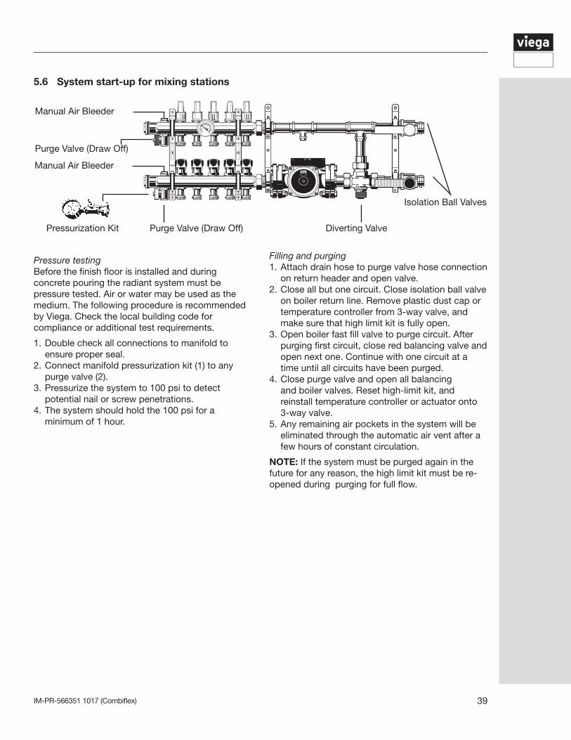
Pressure testingBefore the finish floor is installed and during concrete pouring the radiant system must be pressure tested. Air or water may be used as the medium. The following procedure is recommended by Viega. Check the local building code for compliance or additional test requirements.
1. Double check all connections to manifold to ensure proper seal.2. Connect manifold pressurization kit (1) to any purge valve (2).3. Pressurize the system to 100 psi to detect potential nail or screw penetrations.4. The system should hold the 100 psi for a minimum of 1 hour.
Filling and purging1. Attach drain hose to purge valve hose connection on return header and open valve.2. Close all but one circuit. Close isolation ball valve on boiler return line. Remove plastic dust cap or temperature controller from 3-way valve, and make sure that high limit kit is fully open.3. Open boiler fast fill valve to purge circuit. After purging first circuit, close red balancing valve and open next one. Continue with one circuit at a time until all circuits have been purged.4. Close purge valve and open all balancing and boiler valves. Reset high-limit kit, and reinstall temperature controller or actuator onto 3-way valve.5. Any remaining air pockets in the system will be eliminated through the automatic air vent after a few hours of constant circulation.
NOTE: If the system must be purged again in the future for any reason, the high limit kit must be re-opened during purging for full flow.
5.6 System start-up for mixing stations
Isolation Ball Valves
Diverting ValvePressurization Kit Purge Valve (Draw Off)
Purge Valve (Draw Off)
Manual Air Bleeder
Manual Air Bleeder
IM-PR-566351 1017 (Combiflex)40
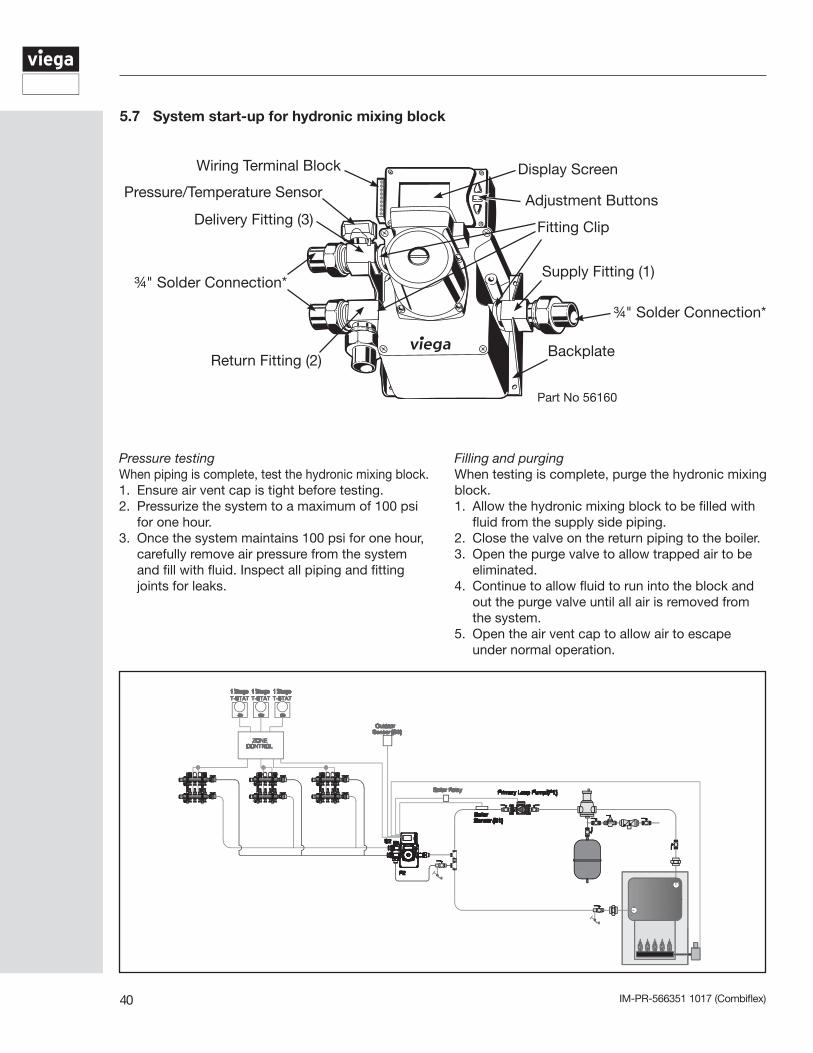
5.7 System start-up for hydronic mixing block
Wiring Terminal Block
Delivery Fitting (3)
¾" Solder Connection*
Return Fitting (2)
Fitting Clip
Supply Fitting (1)
Backplate
Display Screen
Adjustment ButtonsPressure/Temperature Sensor
¾" Solder Connection*
Part No 56160
Pressure testing When piping is complete, test the hydronic mixing block. 1. Ensure air vent cap is tight before testing.2. Pressurize the system to a maximum of 100 psi
for one hour.3. Once the system maintains 100 psi for one hour,
carefully remove air pressure from the system and fill with fluid. Inspect all piping and fitting joints for leaks.
Filling and purging When testing is complete, purge the hydronic mixing block.1. Allow the hydronic mixing block to be filled with
fluid from the supply side piping.2. Close the valve on the return piping to the boiler.3. Open the purge valve to allow trapped air to be
eliminated.4. Continue to allow fluid to run into the block and
out the purge valve until all air is removed from the system.
5. Open the air vent cap to allow air to escape under normal operation.
IM-PR-566351 1017 (Combiflex) 41
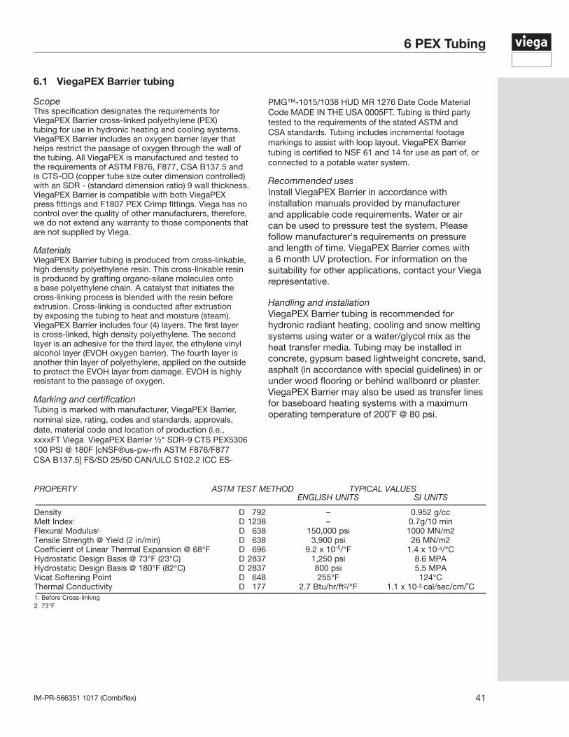
6.1 ViegaPEX Barrier tubing
ScopeThis specification designates the requirements for ViegaPEX Barrier cross-linked polyethylene (PEX) tubing for use in hydronic heating and cooling systems. ViegaPEX Barrier includes an oxygen barrier layer that helps restrict the passage of oxygen through the wall of the tubing. All ViegaPEX is manufactured and tested to the requirements of ASTM F876, F877, CSA B137.5 and is CTS-OD (copper tube size outer dimension controlled) with an SDR - (standard dimension ratio) 9 wall thickness. ViegaPEX Barrier is compatible with both ViegaPEX press fittings and F1807 PEX Crimp fittings. Viega has no control over the quality of other manufacturers, therefore, we do not extend any warranty to those components that are not supplied by Viega.
MaterialsViegaPEX Barrier tubing is produced from cross-linkable, high density polyethylene resin. This cross-linkable resin is produced by grafting organo-silane molecules onto a base polyethylene chain. A catalyst that initiates the cross-linking process is blended with the resin before extrusion. Cross-linking is conducted after extrustion by exposing the tubing to heat and moisture (steam). ViegaPEX Barrier includes four (4) layers. The first layer is cross-linked, high density polyethylene. The second layer is an adhesive for the third layer, the ethylene vinyl alcohol layer (EVOH oxygen barrier). The fourth layer is another thin layer of polyethylene, applied on the outside to protect the EVOH layer from damage. EVOH is highly resistant to the passage of oxygen.
Marking and certificationTubing is marked with manufacturer, ViegaPEX Barrier, nominal size, rating, codes and standards, approvals, date, material code and location of production (i.e., xxxxFT Viega ViegaPEX Barrier ½" SDR-9 CTS PEX5306 100 PSI @ 180F [cNSF®us-pw-rfh ASTM F876/F877 CSA B137.5] FS/SD 25/50 CAN/ULC S102.2 ICC ES-
PROPERTY ASTM TEST METHOD TYPICAL VALUES ENGLISH UNITS SI UNITS
Density D 792 – 0.952 g/ccMelt Index1 D 1238 – 0.7g/10 minFlexural Modulus2 D 638 150,000 psi 1000 MN/m2Tensile Strength @ Yield (2 in/min) D 638 3,900 psi 26 MN/m2Coefficient of Linear Thermal Expansion @ 68°F D 696 9.2 x 10⁻⁵/°F 1.4 x 10⁻⁴/°CHydrostatic Design Basis @ 73°F (23°C) D 2837 1,250 psi 8.6 MPAHydrostatic Design Basis @ 180°F (82°C) D 2837 800 psi 5.5 MPAVicat Softening Point D 648 255°F 124°CThermal Conductivity D 177 2.7 Btu/hr/ft2/°F 1.1 x 10⁻³ cal/sec/cm/˚C1. Before Cross-linking2. 73°F
PMG™-1015/1038 HUD MR 1276 Date Code Material Code MADE IN THE USA 0005FT. Tubing is third party tested to the requirements of the stated ASTM and CSA standards. Tubing includes incremental footage markings to assist with loop layout. ViegaPEX Barrier tubing is certified to NSF 61 and 14 for use as part of, or connected to a potable water system.
Recommended usesInstall ViegaPEX Barrier in accordance with installation manuals provided by manufacturer and applicable code requirements. Water or air can be used to pressure test the system. Please follow manufacturer's requirements on pressure and length of time. ViegaPEX Barrier comes with a 6 month UV protection. For information on the suitability for other applications, contact your Viega representative.
Handling and installationViegaPEX Barrier tubing is recommended for hydronic radiant heating, cooling and snow melting systems using water or a water/glycol mix as the heat transfer media. Tubing may be installed in concrete, gypsum based lightweight concrete, sand, asphalt (in accordance with special guidelines) in or under wood flooring or behind wallboard or plaster. ViegaPEX Barrier may also be used as transfer lines for baseboard heating systems with a maximum operating temperature of 200˚F @ 80 psi.
6 PEX Tubing
IM-PR-566351 1017 (Combiflex)42
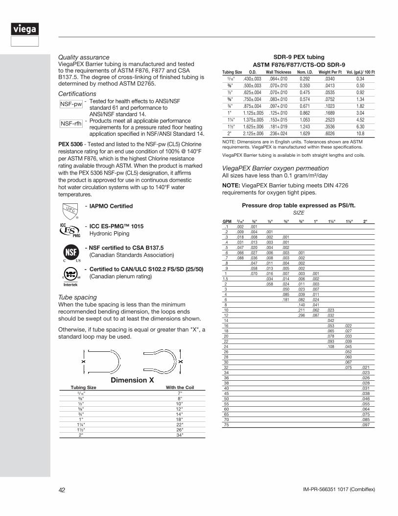
Quality assuranceViegaPEX Barrier tubing is manufactured and tested to the requirements of ASTM F876, F877 and CSA B137.5. The degree of cross-linking of finished tubing is determined by method ASTM D2765.
Certifications - Tested for health effects to ANSI/NSF standard 61 and performance to ANSI/NSF standard 14. - Products meet all applicable performance requirements for a pressure rated floor heating application specified in NSF/ANSI Standard 14.
PEX 5306 - Tested and listed to the NSF-pw (CL5) Chlorine resistance rating for an end use condition of 100% @ 140°F per ASTM F876, which is the highest Chlorine resistance rating available through ASTM. When the product is marked with the PEX 5306 NSF-pw (CL5) designation, it affirms the product is approved for use in continuous domestic hot water circulation systems with up to 140°F water temperatures.
- IAPMO Certified
- ICC ES-PMG™ 1015 Hydronic Piping
- NSF certified to CSA B137.5 (Canadian Standards Association)
- Certified to CAN/ULC S102.2 FS/SD (25/50) (Canadian plenum rating)
Tube spacingWhen the tube spacing is less than the minimum recommended bending dimension, the loops ends should be swept out to at least the dimensions shown.
Otherwise, if tube spacing is equal or greater than "X", a standard loop may be used.
ViegaPEX Barrier oxygen permeationAll sizes have less than 0.1 gram/m³/day
NOTE: ViegaPEX Barrier tubing meets DIN 4726 requirements for oxygen tight pipes.
SDR-9 PEX tubingASTM F876/F877/CTS-OD SDR-9
Tubing Size O.D. Wall Thickness Nom. I.D. Weight Per Ft Vol. (gal.)/ 100 Ft 5/16" .430±.003 .064+.010 0.292 .0340 0.34 ⅜" .500±.003 .070+.010 0.350 .0413 0.50 ½" .625±.004 .070+.010 0.475 .0535 0.92 ⅝" .750±.004 .083+.010 0.574 .0752 1.34 ¾" .875±.004 .097+.010 0.671 .1023 1.82 1" 1.125±.005 .125+.010 0.862 .1689 3.04 1¼" 1.375±.005 .153+.015 1.053 .2523 4.52 1½" 1.625±.006 .181+.019 1.243 .3536 6.30 2" 2.125±.006 .236+.024 1.629 .6026 10.8
NOTE: Dimensions are in English units. Tolerances shown are ASTM requirements. ViegaPEX is manufactured within these specifications.
ViegaPEX Barrier tubing is available in both straight lengths and coils.
Dimension XTubing Size With the Coil
5/16" 7" ⅜" 8" ½" 10" ⅝" 12" ¾" 14" 1" 18" 1¼" 22" 1½" 26" 2" 34"
Pressure drop table expressed as PSI/ft.SIZE
GPM 5/16" ⅜" ½" ⅝" ¾" 1" 1¼" 1½" 2" .1 .002 .001 .2 .009 .004 .001 .3 .018 .008 .002 .001 .4 .031 .013 .003 .001 .5 .047 .020 .004 .002 .6 .066 .027 .006 .003 .001 .7 .088 .036 .008 .003 .002 .8 .047 .011 .004 .002 .9 .058 .013 .005 .002 1 .070 .016 .007 .003 .0011.5 .034 .014 .006 .002 2 .058 .024 .011 .003 3 .050 .023 .007 4 .085 .039 .011 6 .181 .082 .024 8 .140 .041 10 .211 .062 .023 12 .296 .087 .032 14 .042 16 .053 .022 18 .065 .027 20 .078 .033 22 .093 .039 24 .108 .045 26 .052 28 .060 30 .067 32 .075 .021 34 .023 36 .026 38 .028 40 .031 45 .038 50 .046 55 .055 60 .064 65 .075 70 .085 75 .097
NSF-rfh
NSF-pw
IM-PR-566351 1017 (Combiflex) 43
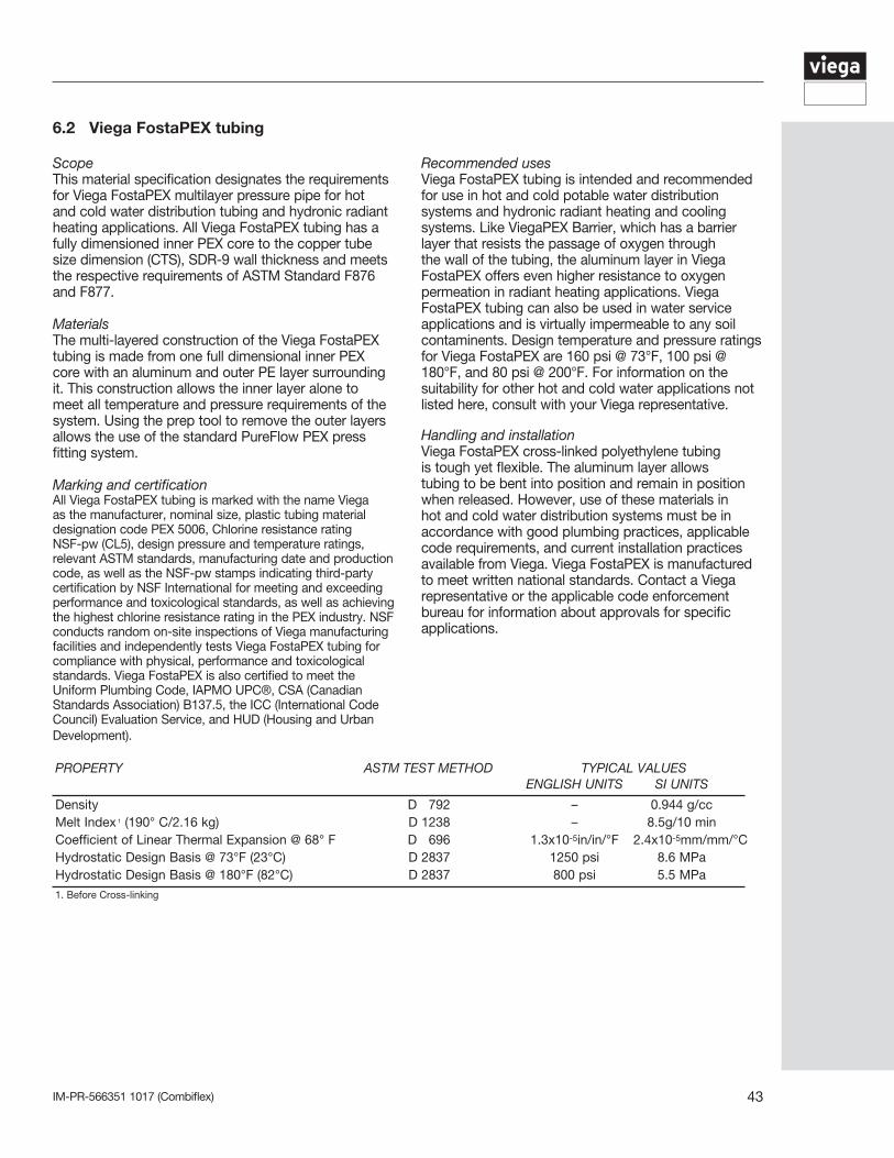
6.2 Viega FostaPEX tubing
ScopeThis material specification designates the requirements for Viega FostaPEX multilayer pressure pipe for hot and cold water distribution tubing and hydronic radiant heating applications. All Viega FostaPEX tubing has a fully dimensioned inner PEX core to the copper tube size dimension (CTS), SDR-9 wall thickness and meets the respective requirements of ASTM Standard F876 and F877.
MaterialsThe multi-layered construction of the Viega FostaPEX tubing is made from one full dimensional inner PEX core with an aluminum and outer PE layer surrounding it. This construction allows the inner layer alone to meet all temperature and pressure requirements of the system. Using the prep tool to remove the outer layers allows the use of the standard PureFlow PEX press fitting system.
Marking and certificationAll Viega FostaPEX tubing is marked with the name Viega as the manufacturer, nominal size, plastic tubing material designation code PEX 5006, Chlorine resistance rating NSF-pw (CL5), design pressure and temperature ratings, relevant ASTM standards, manufacturing date and production code, as well as the NSF-pw stamps indicating third-party certification by NSF International for meeting and exceeding performance and toxicological standards, as well as achieving the highest chlorine resistance rating in the PEX industry. NSF conducts random on-site inspections of Viega manufacturing facilities and independently tests Viega FostaPEX tubing for compliance with physical, performance and toxicological standards. Viega FostaPEX is also certified to meet the Uniform Plumbing Code, IAPMO UPC®, CSA (Canadian Standards Association) B137.5, the ICC (International Code Council) Evaluation Service, and HUD (Housing and Urban Development).
PROPERTY ASTM TEST METHOD TYPICAL VALUES ENGLISH UNITS SI UNITS
Density D 792 – 0.944 g/ccMelt Index 1 (190° C/2.16 kg) D 1238 – 8.5g/10 minCoefficient of Linear Thermal Expansion @ 68° F D 696 1.3x10⁻⁵in/in/°F 2.4x10⁻⁵mm/mm/°CHydrostatic Design Basis @ 73°F (23°C) D 2837 1250 psi 8.6 MPaHydrostatic Design Basis @ 180°F (82°C) D 2837 800 psi 5.5 MPa1. Before Cross-linking
Recommended usesViega FostaPEX tubing is intended and recommended for use in hot and cold potable water distribution systems and hydronic radiant heating and cooling systems. Like ViegaPEX Barrier, which has a barrier layer that resists the passage of oxygen through the wall of the tubing, the aluminum layer in Viega FostaPEX offers even higher resistance to oxygen permeation in radiant heating applications. Viega FostaPEX tubing can also be used in water service applications and is virtually impermeable to any soil contaminents. Design temperature and pressure ratings for Viega FostaPEX are 160 psi @ 73°F, 100 psi @ 180°F, and 80 psi @ 200°F. For information on the suitability for other hot and cold water applications not listed here, consult with your Viega representative.
Handling and installationViega FostaPEX cross-linked polyethylene tubing is tough yet flexible. The aluminum layer allows tubing to be bent into position and remain in position when released. However, use of these materials in hot and cold water distribution systems must be in accordance with good plumbing practices, applicable code requirements, and current installation practices available from Viega. Viega FostaPEX is manufactured to meet written national standards. Contact a Viega representative or the applicable code enforcement bureau for information about approvals for specific applications.
IM-PR-566351 1017 (Combiflex)44
Pressure drop tableExpressed as PSI/ft. pressure drop
SIZE GPM ½" ⅝" ¾" 1" 1 .016 .007 .003 .001 1.5 .034 .014 .006 .002 2.2 .069 .034 .013 .004 2.5 .087 .043 .016 .005 3 .122 .050 .023 .007 3.5 .162 .080 .030 .009 4 .208* .100 .039 .011 5 .314 .154 .059 .017 6 .440 .181 .082 .024 7 .586 .287 .109 .032 8 .368 .140 .041 9 .457 .174* .051 10 .556 .211 .062 11 .252 .074 12 .296 .087 13 .343 .101 14 .116 15 .132* 16 .148 17 .166 18 .184 19 .204 20 .224 21 .245 22 .267
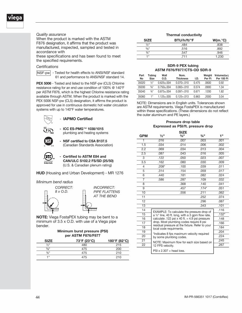
Quality assuranceWhen the product is marked with the ASTM F876 designation, it affirms that the product was manufactured, inspected, sampled and tested in accordance with these specifications and has been found to meet the specified requirements.
Certifications
- Tested for health effects to ANSI/NSF standard 61 and performance to ANSI/NSF standard 14.
PEX 5006 - Tested and listed to the NSF-pw (CL5) Chlorine resistance rating for an end use condition of 100% @ 140°F per ASTM F876, which is the highest Chlorine resistance rating available through ASTM. When the product is marked with the PEX 5006 NSF-pw (CL5) designation, it affirms the product is approved for use in continuous domestic hot water circulation systems with up to 140°F water temperatures.
- IAPMO Certified
- ICC ES-PMG™ 1038/1015 plumbing and heating systems
- NSF certified to CSA B137.5 (Canadian Standards Association)
- Certified to ASTM E84 and CAN/ULC S102.2 FS/SD (25/50) (U.S. & Canadian plenum rating)
HUD (Housing and Urban Development) - MR 1276
SDR-9 PEX tubingASTM F876/F877/CTS-OD SDR-9
Part Tubing Wall Nom. Weight Volume(Gal.) No Size O.D. Thickness I.D. Per Ft Per 100 Ft
35020 ½" 0.625±.004 0.070+.010 0.475 .0600 0.92 35030 ⅝" 0.750±.004 0.083+.010 0.574 .0900 1.34 35040 ¾" 0.875±.004 0.097+.010 0.671 .1200 1.82
35060 1" 1.125±.005 0.125+.013 0.863 .2000 3.04
NOTE: Dimensions are in English units. Tolerances shown are ASTM requirements. Viega FostaPEX is manufactured within these specifications. (These dimensions do not reflect the outer aluminum and PE layers.)
Minimum bend radiusCORRECT: 8 x O.D.
INCORRECT:PIPE FLATTENS AT THE BEND
Thermal conductivity SIZE BTU/h/ft/°F W(m.°C) ½" .484 .838 ⅝" .516 .892 ¾" .547 .946 1" .711 1.230
Minimum burst pressure (PSI) per ASTM F876/F877
SIZE 73°F (23°C) 180°F (82°C) ½" 480 215 ⅝" 475 200 ¾" 475 210 1" 475 210
EXAMPLE: To calculate the pressure drop of a ½" line, 40 ft. long, with a 3 gpm flow rate, calculate .122 psi x 40 ft. = 4.9 psi pressure drop. Most plumbing codes require 8 psi residual pressure at the fixture. Refer to your local code requirments.
*Indicates 8 fps maximum velocity required by some plumbing codes.
NOTE: Maximum flow for each size based on 12 FPS velocity.
PSI x 2.307 = head loss.
NOTE: Viega FostaPEX tubing may be bent to a minimum of 3.5 x O.D. with use of a Viega pipe bender.
IM-PR-566351 1017 (Combiflex) 45
Appendix A
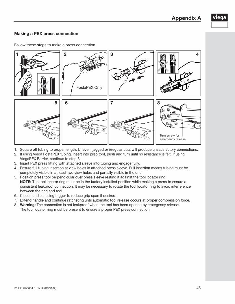
1. Square off tubing to proper length. Uneven, jagged or irregular cuts will produce unsatisfactory connections.2. If using Viega FostaPEX tubing, insert into prep tool, push and turn until no resistance is felt. If using
ViegaPEX Barrier, continue to step 3.3. Insert PEX press fitting with attached sleeve into tubing and engage fully. 4. Ensure full tubing insertion at view holes in attached press sleeve. Full insertion means tubing must be completely visible in at least two view holes and partially visible in the one.5. Position press tool perpendicular over press sleeve resting it against the tool locator ring. NOTE: The tool locator ring must be in the factory installed position while making a press to ensure a consistent leakproof connection. It may be necessary to rotate the tool locator ring to avoid interference between the ring and tool.6. Close handles, using trigger to reduce grip span if desired.7. Extend handle and continue ratcheting until automatic tool release occurs at proper compression force.8. Warning: The connection is not leakproof when the tool has been opened by emergency release. The tool locator ring must be present to ensure a proper PEX press connection.
PureFlow1/2”
PureFlow
1/2”
PureFlow
1/2”PureFlow1/2”
5
Turn screw for emergency release.
Follow these steps to make a press connection.
1 2 3 4
6 7 8
FostaPEX Only
Making a PEX press connection
IM-PR-566351 1017 (Combiflex)46
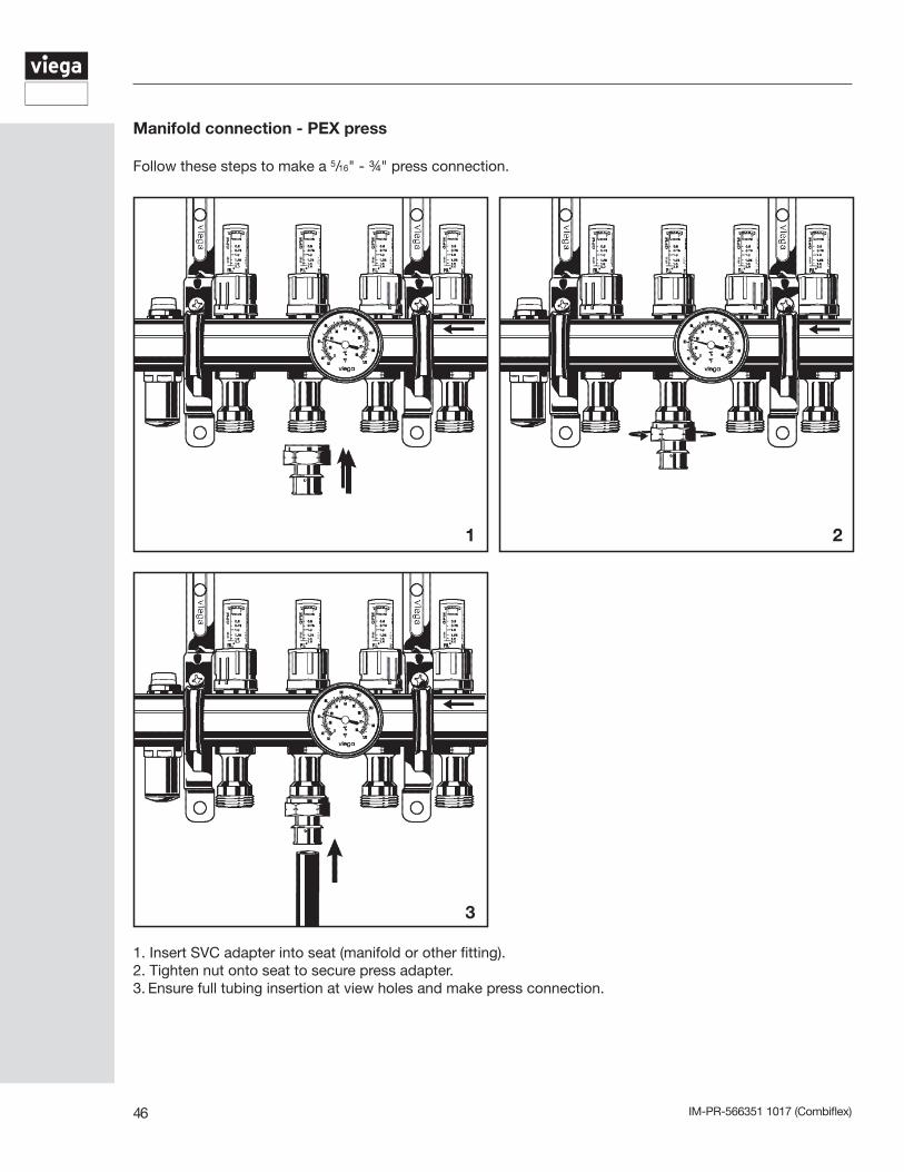
Follow these steps to make a 5/16" - ¾" press connection.
1. Insert SVC adapter into seat (manifold or other fitting).2. Tighten nut onto seat to secure press adapter.3. Ensure full tubing insertion at view holes and make press connection.
1 2
3
Manifold connection - PEX press
IM-PR-566351 1017 (Combiflex) 47
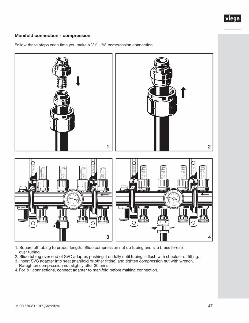
Follow these steps each time you make a 5/16" - ¾" compression connection.
1. Square off tubing to proper length. Slide compression nut up tubing and slip brass ferrule over tubing.2. Slide tubing over end of SVC adapter, pushing it on fully until tubing is flush with shoulder of fitting.3. Insert SVC adapter into seat (manifold or other fitting) and tighten compression nut with wrench. Re-tighten compression nut slightly after 30 mins.4. For ¾" connections, connect adapter to manifold before making connection.
1 2
3 4
Manifold connection - compression
IM-PR-566351 1017 (Combiflex)48
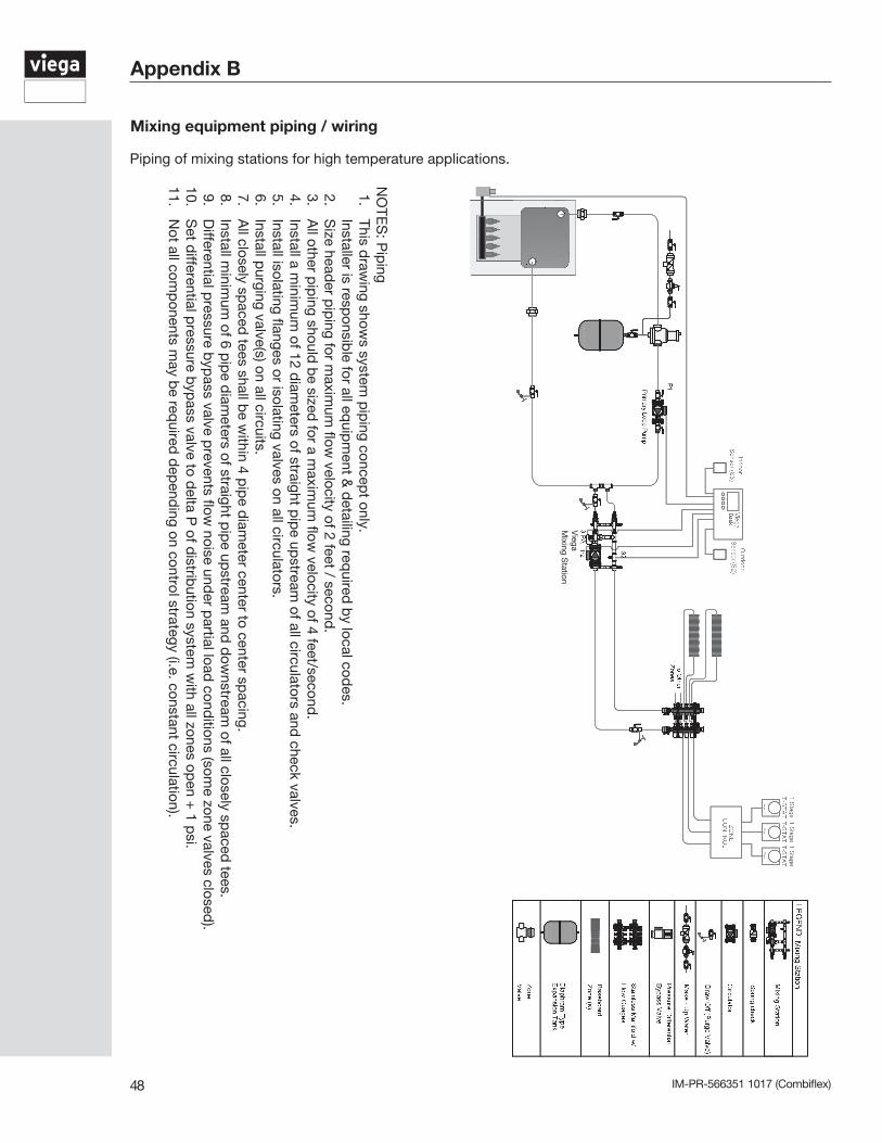
Piping of mixing stations for high temperature applications.
Appendix B
NO
TES
: Pip
ing1.
This draw
ing shows system
pip
ing concept only.
Installer is responsib
le for all equip
ment &
detailing req
uired b
y local codes.
2. S
ize header p
iping for m
aximum
flow velocity of 2 feet / second
.3.
All other p
iping should
be sized
for a maxim
um flow
velocity of 4 feet/second.
4. Install a m
inimum
of 12 diam
eters of straight pip
e upstream
of all circulators and check valves.
5. Install isolating flanges or isolating valves on all circulators.
6. Install p
urging valve(s) on all circuits.7.
All closely sp
aced tees shall b
e within 4 p
ipe d
iameter center to center sp
acing.8.
Install minim
um of 6 p
ipe d
iameters of straight p
ipe up
stream and
dow
nstream of all closely sp
aced tees.
9. D
ifferential pressure b
ypass valve p
revents flow noise und
er partial load
conditions (som
e zone valves closed).
10. S
et differential p
ressure byp
ass valve to delta P
of distrib
ution system w
ith all zones open +
1 psi.
11. N
ot all comp
onents may b
e required
dep
ending on control strategy (i.e. constant circulation).
Viega
Mixing S
tation
Mixing equipment piping / wiring
IM-PR-566351 1017 (Combiflex) 49
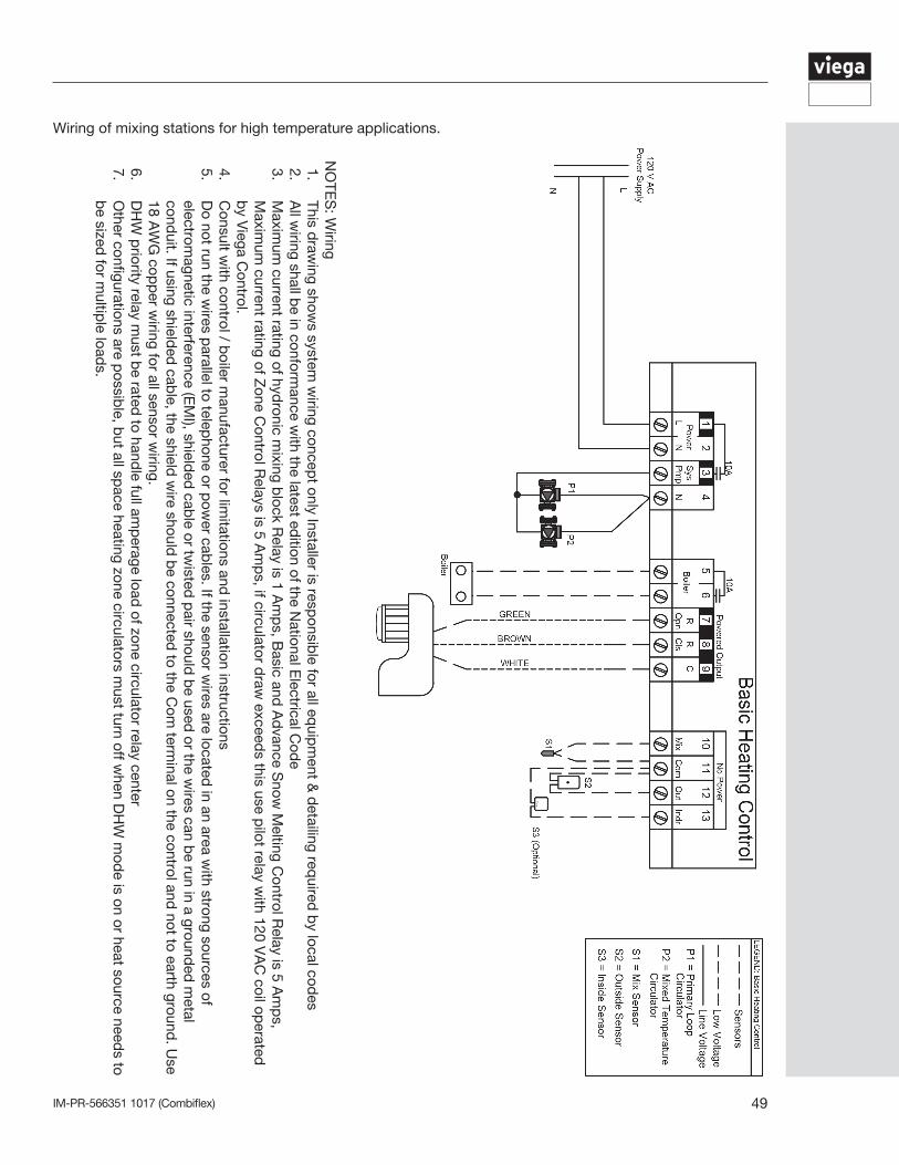
Wiring of mixing stations for high temperature applications.
NO
TES
: Wiring
1. This d
rawing show
s system w
iring concept only Installer is resp
onsible for all eq
uipm
ent & d
etailing required
by local cod
es2.
All w
iring shall be in conform
ance with the latest ed
ition of the National E
lectrical Cod
e3.
Maxim
um current rating of hyd
ronic mixing b
lock Relay is 1 A
mp
s, Basic and
Ad
vance Snow
Melting C
ontrol Relay is 5 A
mp
s, M
aximum
current rating of Zone C
ontrol Relays is 5 A
mp
s, if circulator draw
exceeds this use p
ilot relay with 120 V
AC
coil operated
b
y Viega C
ontrol.4.
Consult w
ith control / boiler m
anufacturer for limitations and
installation instructions5.
Do not run the w
ires parallel to telep
hone or pow
er cables. If the sensor w
ires are located in an area w
ith strong sources of electrom
agnetic interference (EM
I), shielded
cable or tw
isted p
air should b
e used or the w
ires can be run in a ground
ed m
etal cond
uit. If using shielded
cable, the shield
wire should
be connected
to the Com
terminal on the control and
not to earth ground. U
se 18 A
WG
copp
er wiring for all sensor w
iring.6.
DH
W p
riority relay must b
e rated to hand
le full amp
erage load of zone circulator relay center
7. O
ther configurations are possib
le, but all sp
ace heating zone circulators must turn off w
hen DH
W m
ode is on or heat source need
s to b
e sized for m
ultiple load
s.
IM-PR-566351 1017 (Combiflex)50
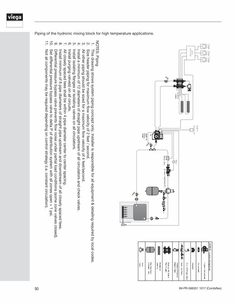
Piping of the hydronic mixing block for high temperature applications.
NO
TES
: Pip
ing1.
This draw
ing shows system
pip
ing concept only. Installer is resp
onsible for all eq
uipm
ent & d
etailing required
by local cod
es.2.
Size head
er pip
ing for maxim
um flow
velocity of 2 feet / second.
3. A
ll other pip
ing should b
e sized for a m
aximum
flow velocity of 4 feet/second
.4.
Install a minim
um of 12 d
iameters of straight p
ipe up
stream of all circulators and
check valves.5.
Install isolating flanges or isolating valves on all circulators.6.
Install purging valve(s) on all circuits.
7. A
ll closely spaced
tees shall be w
ithin 4 pip
e diam
eter center to center spacing.
8. Install m
inimum
of 6 pip
e diam
eters of straight pip
e upstream
and d
ownstream
of all closely spaced
tees.9.
Differential p
ressure byp
ass valve prevents flow
noise under p
artial load cond
itions (some zone valves closed
).10.
Set d
ifferential pressure b
ypass valve to d
elta P of d
istribution system
with all zones op
en + 1 p
si.11.
Not all com
ponents m
ay be req
uired d
epend
ing on control strategy (i.e. constant circulation).
IM-PR-566351 1017 (Combiflex) 51
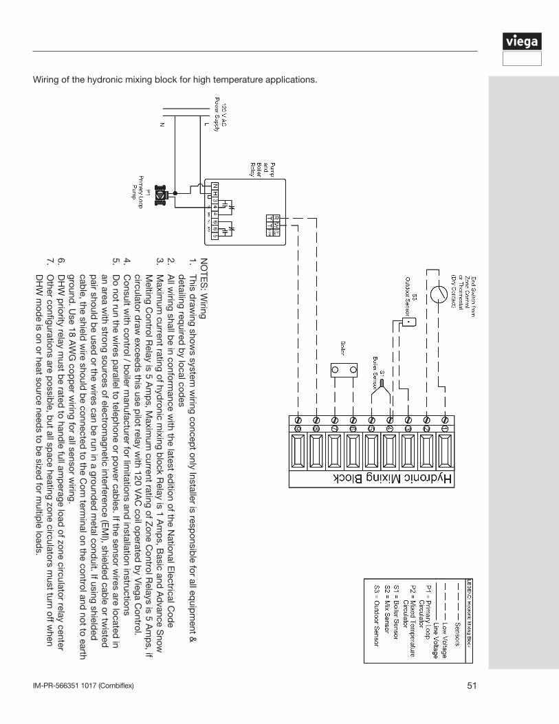
Wiring of the hydronic mixing block for high temperature applications.
NO
TES
: Wiring
1. This d
rawing show
s system w
iring concept only Installer is resp
onsible for all eq
uipm
ent &
detailing req
uired b
y local codes
2. A
ll wiring shall b
e in conformance w
ith the latest edition of the N
ational Electrical C
ode
3. M
aximum
current rating of hydronic m
ixing block R
elay is 1 Am
ps, B
asic and A
dvance S
now
Melting C
ontrol Relay is 5 A
mp
s, Maxim
um current rating of Z
one Control R
elays is 5 Am
ps, if
circulator draw
exceeds this use p
ilot relay with 120 V
AC
coil operated
by V
iega Control.
4. C
onsult with control / b
oiler manufacturer for lim
itations and installation instructions
5. D
o not run the wires p
arallel to telephone or p
ower cab
les. If the sensor wires are located
in an area w
ith strong sources of electromagnetic interference (E
MI), shield
ed cab
le or twisted
p
air should b
e used or the w
ires can be run in a ground
ed m
etal conduit. If using shield
ed
cable, the shield
wire should
be connected
to the Com
terminal on the control and
not to earth ground
. Use 18 A
WG
copp
er wiring for all sensor w
iring.6.
DH
W p
riority relay must b
e rated to hand
le full amp
erage load of zone circulator relay center
7. O
ther configurations are possib
le, but all sp
ace heating zone circulators must turn off w
hen D
HW
mod
e is on or heat source needs to b
e sized for m
ultiple load
s.
IM-PR-566351 1017 (Combiflex)52
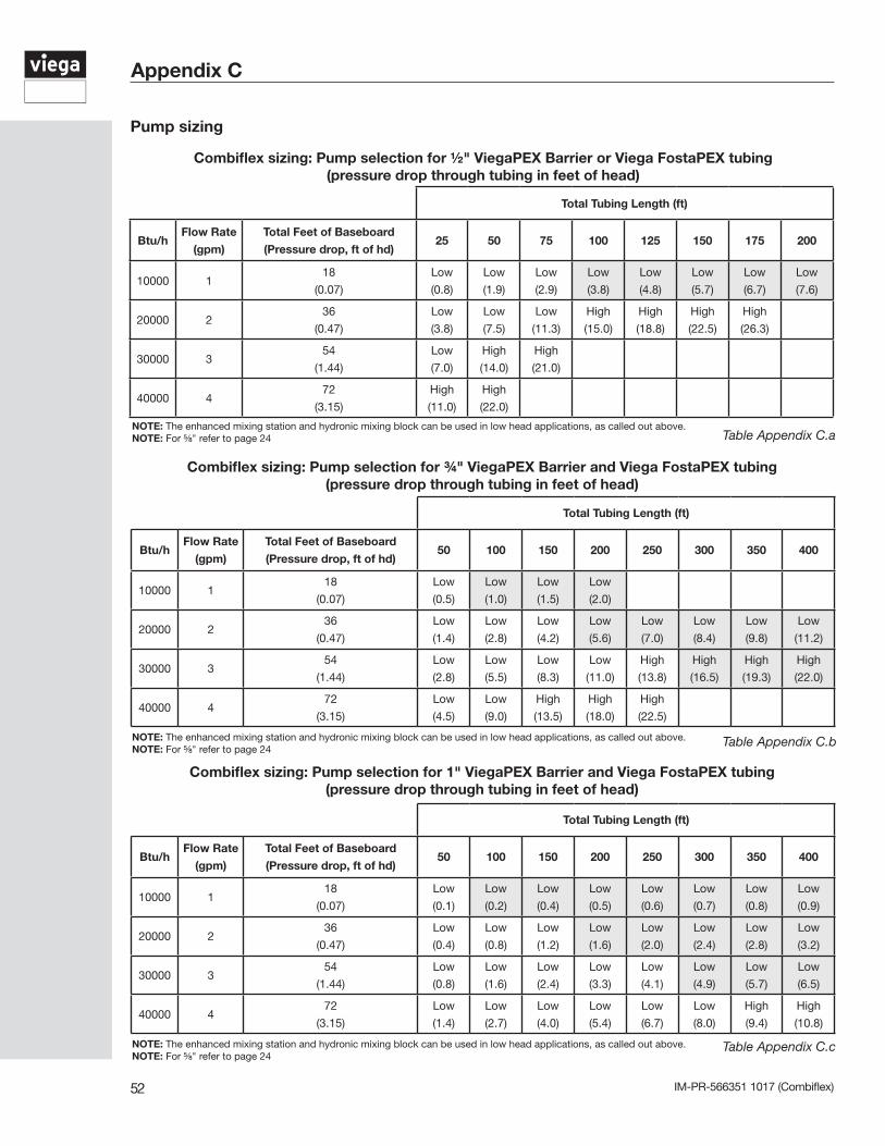
Combiflex sizing: Pump selection for ¾" ViegaPEX Barrier and Viega FostaPEX tubing(pressure drop through tubing in feet of head)
Combiflex sizing: Pump selection for 1" ViegaPEX Barrier and Viega FostaPEX tubing(pressure drop through tubing in feet of head)
Table Appendix C.a
Table Appendix C.b
Table Appendix C.c
Appendix C
Total Tubing Length (ft)
Btu/hFlow Rate
(gpm)
Total Feet of Baseboard
(Pressure drop, ft of hd)25 50 75 100 125 150 175 200
10000 118
(0.07)
Low
(0.8)
Low
(1.9)
Low
(2.9)
Low
(3.8)
Low
(4.8)
Low
(5.7)
Low
(6.7)
Low
(7.6)
20000 236
(0.47)
Low
(3.8)
Low
(7.5)
Low
(11.3)
High
(15.0)
High
(18.8)
High
(22.5)
High
(26.3)
30000 354
(1.44)
Low
(7.0)
High
(14.0)
High
(21.0)
40000 472
(3.15)
High
(11.0)
High
(22.0)
Combiflex sizing: Pump selection for ½" ViegaPEX Barrier or Viega FostaPEX tubing(pressure drop through tubing in feet of head)
Total Tubing Length (ft)
Btu/hFlow Rate
(gpm)
Total Feet of Baseboard
(Pressure drop, ft of hd)50 100 150 200 250 300 350 400
10000 118
(0.07)
Low
(0.5)
Low
(1.0)
Low
(1.5)
Low
(2.0)
20000 236
(0.47)
Low
(1.4)
Low
(2.8)
Low
(4.2)
Low
(5.6)
Low
(7.0)
Low
(8.4)
Low
(9.8)
Low
(11.2)
30000 354
(1.44)
Low
(2.8)
Low
(5.5)
Low
(8.3)
Low
(11.0)
High
(13.8)
High
(16.5)
High
(19.3)
High
(22.0)
40000 472
(3.15)
Low
(4.5)
Low
(9.0)
High
(13.5)
High
(18.0)
High
(22.5)
Total Tubing Length (ft)
Btu/hFlow Rate
(gpm)
Total Feet of Baseboard
(Pressure drop, ft of hd)50 100 150 200 250 300 350 400
10000 118
(0.07)
Low
(0.1)
Low
(0.2)
Low
(0.4)
Low
(0.5)
Low
(0.6)
Low
(0.7)
Low
(0.8)
Low
(0.9)
20000 236
(0.47)
Low
(0.4)
Low
(0.8)
Low
(1.2)
Low
(1.6)
Low
(2.0)
Low
(2.4)
Low
(2.8)
Low
(3.2)
30000 354
(1.44)
Low
(0.8)
Low
(1.6)
Low
(2.4)
Low
(3.3)
Low
(4.1)
Low
(4.9)
Low
(5.7)
Low
(6.5)
40000 472
(3.15)
Low
(1.4)
Low
(2.7)
Low
(4.0)
Low
(5.4)
Low
(6.7)
Low
(8.0)
High
(9.4)
High
(10.8)
NOTE: The enhanced mixing station and hydronic mixing block can be used in low head applications, as called out above.NOTE: For ⅝" refer to page 24
NOTE: The enhanced mixing station and hydronic mixing block can be used in low head applications, as called out above.NOTE: For ⅝" refer to page 24
NOTE: The enhanced mixing station and hydronic mixing block can be used in low head applications, as called out above.NOTE: For ⅝" refer to page 24
Pump sizing

IM-PR-566351 1017 (Combiflex) 53

IM-PR-566351 1017 (Combiflex)54
IM-PR-566351 1017 (Combiflex) 55
Notes

Viega IM-PR-566351 1017 (Combiflex)
Viega LLC12303 Airport Way, Ste. 395 Broomfield, CO 80021 Phone: 1-800-976-9819 Fax: 1-800-976-9817 www.viega.us
This document subject to updates. For the most current Viega technical literature please visit www.viega.us.©2017, Viega®, ProPress®, MegaPress®, SeaPress®, PureFlow®, Smart Connect®, ManaBloc®, GeoFusion®, FostaPEX®, Radiant Wizard®, Climate Panel®, Climate Mat®, and Climate Track® are registered trademarks of Viega GmbH & Co. KG. SmartLoop® and Viega Eco Plus® are registered trademarks of Viega Holding GmbH & Co. Zero Lead™ and PolyAlloy™ are trademarks of Viega LLC. Eco Brass® is a registered trademark of Mitsubishi Shindoh Co., LTD. RIDGID® is a registered trademark of RIDGID, Inc. LoopCAD® is a registered trademark of Avenir Software Inc. Radel® is a registered trademark of Solvay Advanced Polymers, LLC.


![VATTENTÄTNING Sikadur-Combiflex® SG System...Sikadur-Combiflex® SG System PRODUKTSORTIMENT Egenskaper Sikadur-Combiflex® SG-10 P Sikadur-Combiflex® SG-20 P Bandets tjocklek [mm]](https://img.pdfslide.net/doc/110x75/609a184bac716335b21b5204/vattenttning-sikadur-combiflex-sg-system-sikadur-combiflex-sg-system-produktsortiment.jpg)