Embed Size (px)
Citation preview
September 2010 202-10686-01 v1.3
350 East Plumeria DriveSan Jose, CA 95134USA
ProSafe 20-AP Wireless Controller WC7520Reference Manual
| 2
ProSafe 20-AP Wireless Controller WC7520 Reference Manual
©2010 NETGEAR, Inc. All rights reserved.
No part of this publication may be reproduced, transmitted, transcribed, stored in a retrieval system, or translated into any language in any form or by any means without the written permission of NETGEAR, Inc.
Technical SupportThank you for choosing NETGEAR. To register your product, get the latest product updates, or get support online, visit us at http://support.netgear.com.
Phone (US & Canada only): 1-888-NETGEAR
Phone (Other Countries): See Support information card.
TrademarksNETGEAR, the NETGEAR logo, ReadyNAS, ProSafe, Smart Wizard, and Auto Uplink are trademarks or registered trademarks of NETGEAR, Inc. Microsoft, Windows, Windows NT, and Vista are registered trademarks of Microsoft Corporation. Other brand and product names are registered trademarks or trademarks of their respective holders.
Statement of ConditionsTo improve internal design, operational function, and/or reliability, NETGEAR reserves the right to make changes to the products described in this document without notice. NETGEAR does not assume any liability that may occur due to the use, or application of, the product(s) or circuit layout(s) described herein.
Revision History
Publication Part Number Version Publish Date Comments
202-10686-01 v1.3 September 2010 Added an index and made minor revisions to existing content.
202-10686-01 v1.2 September 2010 Added new content and revised existing content in chapters 1, 2, 4, 5, 9, and 10. Added chapters 11 and 12 and appendix A.
202-10686-01 v1.1 September 2010 Added new content to chapters 1 through 4.
202-10686-01 v1.0 August 2010 Initial publication.
Table of Contents
Chapter 1 Introduction and Overview
Key Features and Capabilities. . . . . . . . . . . . . . . . . . . . . . . . . . . . . . . . . . . 7Package Contents . . . . . . . . . . . . . . . . . . . . . . . . . . . . . . . . . . . . . . . . . . . . 9Hardware Features . . . . . . . . . . . . . . . . . . . . . . . . . . . . . . . . . . . . . . . . . . 10
Front Panel Ports and LEDs . . . . . . . . . . . . . . . . . . . . . . . . . . . . . . . . . 10Rear Panel Features . . . . . . . . . . . . . . . . . . . . . . . . . . . . . . . . . . . . . . . 11Bottom Panel With Product Label . . . . . . . . . . . . . . . . . . . . . . . . . . . . . 12
WC7520 Wireless Controller System Components. . . . . . . . . . . . . . . . . . 12NETGEAR ProSafe Access Points: WNAP210 and WNDAP350 . . . . . 13
What Can You Do With the WC7520 Wireless Controller? . . . . . . . . . . . . 13Licenses . . . . . . . . . . . . . . . . . . . . . . . . . . . . . . . . . . . . . . . . . . . . . . . . . . 15Maintenance and Support . . . . . . . . . . . . . . . . . . . . . . . . . . . . . . . . . . . . . 16Understanding the Web Management Interface Menu Layout . . . . . . . . . 16Initial Connection and Configuration . . . . . . . . . . . . . . . . . . . . . . . . . . . . . 17Understanding Basic and Advanced Settings . . . . . . . . . . . . . . . . . . . . . . 19Choosing a Location for the Wireless Controller . . . . . . . . . . . . . . . . . . . . 21Deploying the Wireless Controller . . . . . . . . . . . . . . . . . . . . . . . . . . . . . . . 21
Chapter 2 System Planning and Deployment Scenarios
System Planning . . . . . . . . . . . . . . . . . . . . . . . . . . . . . . . . . . . . . . . . . . . . 22Pre-Installation Planning . . . . . . . . . . . . . . . . . . . . . . . . . . . . . . . . . . . . 22Before You Configure a Wireless Controller . . . . . . . . . . . . . . . . . . . . . 23Single Controller Configuration with Basic Profile Group . . . . . . . . . . . 25Single Controller Configuration with Access Point Groups . . . . . . . . . . 26Stacked Controller Configuration. . . . . . . . . . . . . . . . . . . . . . . . . . . . . . 27
Management VLAN and Data VLAN Strategies . . . . . . . . . . . . . . . . . . . . 27Deployment Scenarios . . . . . . . . . . . . . . . . . . . . . . . . . . . . . . . . . . . . . . . 29
Scenario Example 1: Basic Network with Single VLAN. . . . . . . . . . . . . 29Scenario Example 2: Advanced Network with VLANs and SSIDs. . . . . 31Scenario Example 3: Advanced Network With Redundancy . . . . . . . . . 33
Chapter 3 RF Planning
RF Planning Overview. . . . . . . . . . . . . . . . . . . . . . . . . . . . . . . . . . . . . . . . 36Planning Requirements . . . . . . . . . . . . . . . . . . . . . . . . . . . . . . . . . . . . . 37
Defining and Editing Buildings and Floors. . . . . . . . . . . . . . . . . . . . . . . . . 38Specifying Access Point Requirements. . . . . . . . . . . . . . . . . . . . . . . . . . . 40Viewing and Managing Heat Maps for Deployed Plans . . . . . . . . . . . . . . 42
Table of Contents | 3
ProSafe 20-AP Wireless Controller WC7520 Reference Manual
Chapter 4 Access Point Discovery and Management
Access Point Discovery . . . . . . . . . . . . . . . . . . . . . . . . . . . . . . . . . . . . . . . 46Requirements for Auto Discovery. . . . . . . . . . . . . . . . . . . . . . . . . . . . . . . . 46Using the Discovery Wizard . . . . . . . . . . . . . . . . . . . . . . . . . . . . . . . . . . . . 47Understanding the Discovery Results . . . . . . . . . . . . . . . . . . . . . . . . . . . . 49Managing the Access Point List . . . . . . . . . . . . . . . . . . . . . . . . . . . . . . . . . 50
Adding Access Points to the Managed List After Discovery. . . . . . . . . . 50Editing Access Point Information . . . . . . . . . . . . . . . . . . . . . . . . . . . . . . 51
Chapter 5 Configuring Network Settings
Configuring General Settings . . . . . . . . . . . . . . . . . . . . . . . . . . . . . . . . . . . 54Time Management . . . . . . . . . . . . . . . . . . . . . . . . . . . . . . . . . . . . . . . . . . . 56Configuring IP and VLAN Settings . . . . . . . . . . . . . . . . . . . . . . . . . . . . . . . 57
Management VLANs . . . . . . . . . . . . . . . . . . . . . . . . . . . . . . . . . . . . . . . 58Untagged VLANs . . . . . . . . . . . . . . . . . . . . . . . . . . . . . . . . . . . . . . . . . . 58
Managing the DHCP Server . . . . . . . . . . . . . . . . . . . . . . . . . . . . . . . . . . . . 59Managing Certificates. . . . . . . . . . . . . . . . . . . . . . . . . . . . . . . . . . . . . . . . . 60Configuring Syslog and Alarm Notification Settings . . . . . . . . . . . . . . . . . . 61
Configuring Syslog Settings . . . . . . . . . . . . . . . . . . . . . . . . . . . . . . . . . . 61Configuring Alarm Notification Settings . . . . . . . . . . . . . . . . . . . . . . . . . 62Configuring the Email Notification Server. . . . . . . . . . . . . . . . . . . . . . . . 63
Chapter 6 Managing Access Point Groups
Configuring Access Point Groups. . . . . . . . . . . . . . . . . . . . . . . . . . . . . . . . 65Managing Access Point Groups in the WLAN . . . . . . . . . . . . . . . . . . . . . . 66
Chapter 7 Configuring Wireless Settings
Configuring the Radio. . . . . . . . . . . . . . . . . . . . . . . . . . . . . . . . . . . . . . . . . 69Basic Radio Configuration . . . . . . . . . . . . . . . . . . . . . . . . . . . . . . . . . . . 69Advanced Radio Configuration for Access Point Groups . . . . . . . . . . . . 69
Configuring Wireless Settings . . . . . . . . . . . . . . . . . . . . . . . . . . . . . . . . . . 70Basic Wireless Configuration . . . . . . . . . . . . . . . . . . . . . . . . . . . . . . . . . 71Advanced Wireless Configuration for Access Point Groups. . . . . . . . . . 72
Configuring Channels . . . . . . . . . . . . . . . . . . . . . . . . . . . . . . . . . . . . . . . . . 73Specifying RF Management . . . . . . . . . . . . . . . . . . . . . . . . . . . . . . . . . . . . 75
Basic RF Management . . . . . . . . . . . . . . . . . . . . . . . . . . . . . . . . . . . . . . 76Advanced RF Management for Access Point Groups . . . . . . . . . . . . . . 77
Configuring QoS for Access Point Groups . . . . . . . . . . . . . . . . . . . . . . . . . 78Configuring Load Balancing . . . . . . . . . . . . . . . . . . . . . . . . . . . . . . . . . . . . 79Configuring Rate Limiting . . . . . . . . . . . . . . . . . . . . . . . . . . . . . . . . . . . . . . 81
Basic Rate Limiting. . . . . . . . . . . . . . . . . . . . . . . . . . . . . . . . . . . . . . . . . 81Advanced Rate Limiting for Access Point Groups . . . . . . . . . . . . . . . . . 82
Table of Contents | 4
ProSafe 20-AP Wireless Controller WC7520 Reference Manual
Chapter 8 Configuring Security and Wireless Security Profiles
Managing Wireless Security Profiles . . . . . . . . . . . . . . . . . . . . . . . . . . . . . 83Small-Scale WLAN Networks . . . . . . . . . . . . . . . . . . . . . . . . . . . . . . . . . 84Larger Deployments . . . . . . . . . . . . . . . . . . . . . . . . . . . . . . . . . . . . . . . . 84Configuring Basic Security Profiles . . . . . . . . . . . . . . . . . . . . . . . . . . . . 85Configuring Advanced Security Profiles for Access Point Groups . . . . . 87
Managing Rogue Access Points . . . . . . . . . . . . . . . . . . . . . . . . . . . . . . . . 89Configuring Basic Rogue Detection Settings . . . . . . . . . . . . . . . . . . . . . 89Configuring Advanced Rogue Detection Settings . . . . . . . . . . . . . . . . . 90
Managing MAC Authentication and MAC Authentication Groups . . . . . . . 92Configuring Basic MAC Authentication Settings. . . . . . . . . . . . . . . . . . . 93Configuring MAC Authentication Settings for Groups . . . . . . . . . . . . . . 94
Managing Authentication Servers and Authentication Server Groups . . . . 95Configuring Basic Authentication Server Settings . . . . . . . . . . . . . . . . . 96Configuring Advanced Authentication Server Settings for Groups. . . . . 97
Managing Guest Network Access . . . . . . . . . . . . . . . . . . . . . . . . . . . . . . . 98Configuring Captive Portal Settings . . . . . . . . . . . . . . . . . . . . . . . . . . . . 98
Managing Users and Passwords . . . . . . . . . . . . . . . . . . . . . . . . . . . . . . . 100
Chapter 9 Maintaining the Controller
Managing the Configuration File . . . . . . . . . . . . . . . . . . . . . . . . . . . . . . . 101Backing Up and Restoring the Configuration File. . . . . . . . . . . . . . . . . 102Upgrading the Configuration File . . . . . . . . . . . . . . . . . . . . . . . . . . . . . 103
Rebooting or Resetting the Wireless Controller . . . . . . . . . . . . . . . . . . . . 105Rebooting Access Points . . . . . . . . . . . . . . . . . . . . . . . . . . . . . . . . . . . . . 107Managing External Storage . . . . . . . . . . . . . . . . . . . . . . . . . . . . . . . . . . . 107Managing Remote Access . . . . . . . . . . . . . . . . . . . . . . . . . . . . . . . . . . . . 108
Specifying Session Timeouts . . . . . . . . . . . . . . . . . . . . . . . . . . . . . . . . 110Viewing Alerts and Events and Saving Logs . . . . . . . . . . . . . . . . . . . . . . 110
Saving Logs . . . . . . . . . . . . . . . . . . . . . . . . . . . . . . . . . . . . . . . . . . . . . 111Viewing Alerts and Events . . . . . . . . . . . . . . . . . . . . . . . . . . . . . . . . . . 111
Managing Licenses . . . . . . . . . . . . . . . . . . . . . . . . . . . . . . . . . . . . . . . . . 115Viewing Your Licenses . . . . . . . . . . . . . . . . . . . . . . . . . . . . . . . . . . . . . 116Configuring the License Server Settings . . . . . . . . . . . . . . . . . . . . . . . 117Registering Your Licenses . . . . . . . . . . . . . . . . . . . . . . . . . . . . . . . . . . 118
Chapter 10 Managing Stacking and Redundancy
Managing Stacking. . . . . . . . . . . . . . . . . . . . . . . . . . . . . . . . . . . . . . . . . . 119Configuring Stacking . . . . . . . . . . . . . . . . . . . . . . . . . . . . . . . . . . . . . . 120Controller Selection Menu . . . . . . . . . . . . . . . . . . . . . . . . . . . . . . . . . . 121
Managing Redundancy . . . . . . . . . . . . . . . . . . . . . . . . . . . . . . . . . . . . . . 121Configuring Redundancy . . . . . . . . . . . . . . . . . . . . . . . . . . . . . . . . . . . 122
Table of Contents | 5
ProSafe 20-AP Wireless Controller WC7520 Reference Manual
Chapter 11 Monitoring the Wireless Network and Components
Monitoring the Network . . . . . . . . . . . . . . . . . . . . . . . . . . . . . . . . . . . . . . 124Viewing the Network Summary Screen . . . . . . . . . . . . . . . . . . . . . . . . 125Viewing Network Usage . . . . . . . . . . . . . . . . . . . . . . . . . . . . . . . . . . . . 126Viewing Wireless Controllers in the Network . . . . . . . . . . . . . . . . . . . . 127Viewing Managed Access Points in the Network . . . . . . . . . . . . . . . . . 127Viewing Clients in the Network . . . . . . . . . . . . . . . . . . . . . . . . . . . . . . . 131Viewing Security Profiles in the Network . . . . . . . . . . . . . . . . . . . . . . . 133
Monitoring the Wireless Controller . . . . . . . . . . . . . . . . . . . . . . . . . . . . . . 134Viewing the Wireless Controller Summary Screens . . . . . . . . . . . . . . . 135Viewing Wireless Controller Usage . . . . . . . . . . . . . . . . . . . . . . . . . . . 136Viewing Access Points Managed by the Wireless Controller . . . . . . . . 137Viewing Clients Managed by the Wireless Controller. . . . . . . . . . . . . . 137Viewing Rogue Access Points Managed by the Wireless Controller . . 138Viewing Security Profiles Managed by the Wireless Controller . . . . . . 139Viewing DHCP Leases Provided by the Wireless Controller . . . . . . . . 140Viewing Captive Portal Users Managed by the Wireless Controller. . . 141
Monitoring the SSIDs . . . . . . . . . . . . . . . . . . . . . . . . . . . . . . . . . . . . . . . . 141Monitoring the Clients. . . . . . . . . . . . . . . . . . . . . . . . . . . . . . . . . . . . . . . . 142
Viewing Local Clients . . . . . . . . . . . . . . . . . . . . . . . . . . . . . . . . . . . . . . 142Viewing Blacklisted Clients. . . . . . . . . . . . . . . . . . . . . . . . . . . . . . . . . . 143
Chapter 12 Troubleshooting
Troubleshooting Basic Functioning . . . . . . . . . . . . . . . . . . . . . . . . . . . . . 144Power LED Not On . . . . . . . . . . . . . . . . . . . . . . . . . . . . . . . . . . . . . . . . 144Test LED Never Turns Off . . . . . . . . . . . . . . . . . . . . . . . . . . . . . . . . . . 145LAN Port LEDs Not On. . . . . . . . . . . . . . . . . . . . . . . . . . . . . . . . . . . . . 145
Troubleshooting the Web Management Interface . . . . . . . . . . . . . . . . . . 145Ethernet Cabling. . . . . . . . . . . . . . . . . . . . . . . . . . . . . . . . . . . . . . . . . 145IP Address Configuration . . . . . . . . . . . . . . . . . . . . . . . . . . . . . . . . . . . 145Internet Browser . . . . . . . . . . . . . . . . . . . . . . . . . . . . . . . . . . . . . . . . . . 146
When You Enter a URL or IP Address a Time-out Error Occurs . . . . . . . 147Troubleshooting a TCP/IP Network Using the Ping Utility . . . . . . . . . . . . 147
Testing the LAN Path to Your Wireless Controller . . . . . . . . . . . . . . . . 147Using the Reset Button to Restore Factory Default Settings . . . . . . . . . . 148Problems with Date and Time . . . . . . . . . . . . . . . . . . . . . . . . . . . . . . . . . 148Problems With Access Points. . . . . . . . . . . . . . . . . . . . . . . . . . . . . . . . . . 149
Using the Diagnostic Tools on the Wireless Controller . . . . . . . . . . . . 149
Appendix A Factory Default Settings and Technical Specifications
Appendix B Notification of Compliance
Index
Table of Contents | 6

1. Introduction and Overview 11
This chapter includes the following sections:• Key Features and Capabilities on this page
• Package Contents on page 9
• Hardware Features on page 10
• WC7520 Wireless Controller System Components on page 12
• What Can You Do With the WC7520 Wireless Controller? on page 13
• Licenses on page 15
• Maintenance and Support on page 16
• Understanding the Web Management Interface Menu Layout on page 16
• Initial Connection and Configuration on page 17
• Understanding Basic and Advanced Settings on page 19
• Choosing a Location for the Wireless Controller on page 21
• Deploying the Wireless Controller on page 21
Key Features and Capabilities
The ProSafe 20-AP Wireless Controller WC7520 is intended for medium-sized businesses, schools, and hospitals. In a stacked configuration and with the appropriate licenses, a wireless controller can support up to 150 access points (APs) with up to 1,500 users or more. The wireless controller supports the IEEE 802.11a/b/g protocols and is upgradable to support the IEEE 802.11n protocol. The wireless controller allows you to manage your wireless network from a central point, implement security features centrally, support layer 2 and layer 3 fast roaming, configure a guest access captive portal, and support Voice over Wi-Fi (VoWi-Fi).
Chapter 1: Introduction and Overview | 7
ProSafe 20-AP Wireless Controller WC7520 Reference Manual
The wireless controller provides the following key features and capabilities:
• Scalable architecture with stacking and redundancy
- Support for 20 access points on a single wireless controller with no additional license
- Purchased licenses (WC7510L) in increments of 10 access points allow for support of up to a maximum number of 50 access points on a single wireless controller
- A maximum of three stacked wireless controllers allows for up to 150 access points in a single network
- Support of 1:1 redundancy
- Support of 802.11a, 802.11b, and 802.11g modes by default with the option to purchase a license (WC75NL) to support the 802.11n mode
• Auto discovery of Access Points
- Auto-discovery of access points in the same layer 2 domain
- Auto-discover of access points across a layer 3 domain
- Automatic download of wireless controller-based firmware to discovered access points that are added to the managed access point list.
• Centralized management
- Single point of management for the entire wireless network
- Visualization of live coverage and heat maps for the wireless network
- Automatic firmware upgrade to all managed access points
- DHCP server for IP address provisioning
- Configurable management VLAN
• Security
- Identity-based security authentication with an external AAA server- RADIUS, Active Directory, or internal authentication server
- Up to 8 profiles per group and 8 groups per radio
- Support for up to 128 access point profiles1 per wireless controller (8 profiles per group and 8 groups per radio). Each access point profile supports settings for SSID, network authentication, data encryption, client separation, VLAN, MAC ACL groups, and wireless QoS.
- Support for up 16 access point profile groups2 per wireless controller
- Rogue access point detection and classification
- Guest access and captive portal
- Scheduled wireless on/off times
• Wi-Fi Multimedia Quality of service and advanced wireless features
- Wi-Fi Multimedia (WMM) support for video, audio, and voice over Wi-Fi (VoWi-Fi)
- WMM power save option
- Automatic WLAN healing mechanism ensures seamless coverage for wireless users
1. Number of profiles depends on the access point model used with the wireless controller. 2. Number of profile groups depends on the access point model used with the wireless controller.
Chapter 1: Introduction and Overview | 8
ProSafe 20-AP Wireless Controller WC7520 Reference Manual
- Layer 2 and layer 3 seamless roaming support (FRS)
- Local layer 2 traffic switching at access point level for fast processing and roamed layer 3 traffic processing at controller level
• RF planning and management
- RF planning tool to predict the number and placement of access points based on signal strength and the number of users per building floor, and to display the predicted coverage
- Automatic control of access point transmit power and channel allocation to reduce interference
- Automatic load balancing of clients across access points
- Rate limiting per SSID
• Monitoring and reporting
- Access point heat maps by wireless band and signal strength for real-time status view of the WLAN
- Monitoring of the status of the network, wireless controllers, WLANs, and clients, and network usage statistics
- Specific health monitoring of access points
- Logging and emailing of system events, RF events, load balancing events, rate limiting events, and redundancy failover events
For a list of all features and capabilities of the wireless controller, see the datasheet at http://www.netgear.com/products/service-providers/access-points-wireless-controllers/wireless-management/WC7520.aspx.
Package Contents
The ProSafe 20-AP Wireless Controller WC7520 product package contains the following items:
• ProSafe 20-AP Wireless Controller WC7520 appliance
• One AC power cable
• Rubber feet (4) with adhesive backing
• One rack-mount kit
• Straight-through Category 5 Ethernet cable
• WC7520 ProSafe Wireless Controller Installation Guide
• Resource CD
If any of the parts are incorrect, missing, or damaged, contact your NETGEAR dealer. Keep the carton, including the original packing materials, in case you need to return the product for repair.
Chapter 1: Introduction and Overview | 9
ProSafe 20-AP Wireless Controller WC7520 Reference Manual
Hardware Features
The front panel ports and LEDs, rear panel components, and bottom label of the wireless controller are described in this section.
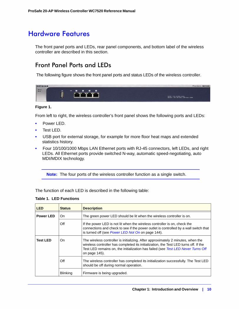
Front Panel Ports and LEDs The following figure shows the front panel ports and status LEDs of the wireless controller.
Figure 1.
From left to right, the wireless controller’s front panel shows the following ports and LEDs:
• Power LED.
• Test LED.
• USB port for external storage, for example for more floor heat maps and extended statistics history.
• Four 10/100/1000 Mbps LAN Ethernet ports with RJ-45 connectors, left LEDs, and right LEDs. All Ethernet ports provide switched N-way, automatic speed-negotiating, auto MDI/MDIX technology.
Note: The four ports of the wireless controller function as a single switch.
The function of each LED is described in the following table:
Table 1. LED Functions
LED Status Description
Power LED On The green power LED should be lit when the wireless controller is on.
Off If the power LED is not lit when the wireless controller is on, check the connections and check to see if the power outlet is controlled by a wall switch that is turned off (see Power LED Not On on page 144).
Test LED On The wireless controller is initializing. After approximately 2 minutes, when the wireless controller has completed its initialization, the Test LED turns off. If the Test LED remains on, the initialization has failed (see Test LED Never Turns Off on page 145).
Off The wireless controller has completed its initialization successfully. The Test LED should be off during normal operation.
Blinking Firmware is being upgraded.
Chapter 1: Introduction and Overview | 10
ProSafe 20-AP Wireless Controller WC7520 Reference Manual
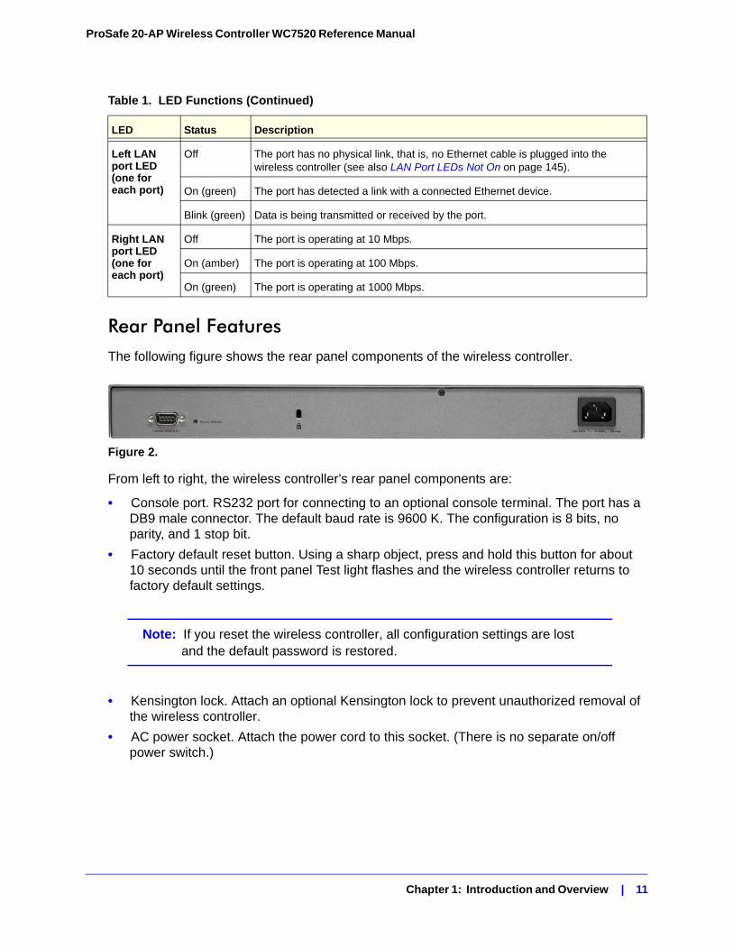
Rear Panel FeaturesThe following figure shows the rear panel components of the wireless controller.
Figure 2.
From left to right, the wireless controller’s rear panel components are:
• Console port. RS232 port for connecting to an optional console terminal. The port has a DB9 male connector. The default baud rate is 9600 K. The configuration is 8 bits, no parity, and 1 stop bit.
• Factory default reset button. Using a sharp object, press and hold this button for about 10 seconds until the front panel Test light flashes and the wireless controller returns to factory default settings.
Note: If you reset the wireless controller, all configuration settings are lost and the default password is restored.
• Kensington lock. Attach an optional Kensington lock to prevent unauthorized removal of the wireless controller.
• AC power socket. Attach the power cord to this socket. (There is no separate on/off power switch.)
Left LAN port LED (one for each port)
Off The port has no physical link, that is, no Ethernet cable is plugged into the wireless controller (see also LAN Port LEDs Not On on page 145).
On (green) The port has detected a link with a connected Ethernet device.
Blink (green) Data is being transmitted or received by the port.
Right LAN port LED (one for each port)
Off The port is operating at 10 Mbps.
On (amber) The port is operating at 100 Mbps.
On (green) The port is operating at 1000 Mbps.
Table 1. LED Functions (Continued)
LED Status Description
Chapter 1: Introduction and Overview | 11
ProSafe 20-AP Wireless Controller WC7520 Reference Manual
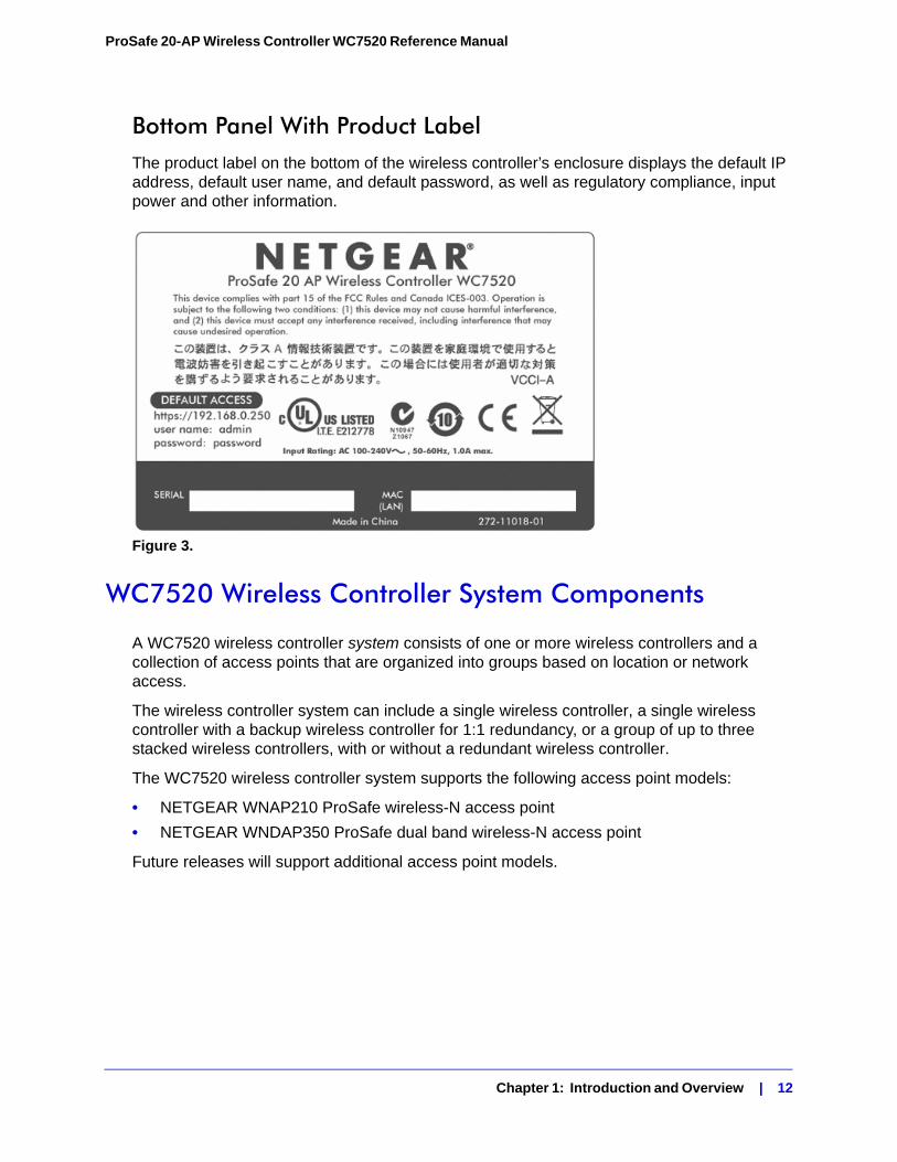
Bottom Panel With Product LabelThe product label on the bottom of the wireless controller’s enclosure displays the default IP address, default user name, and default password, as well as regulatory compliance, input power and other information.
Figure 3.
WC7520 Wireless Controller System Components
A WC7520 wireless controller system consists of one or more wireless controllers and a collection of access points that are organized into groups based on location or network access.
The wireless controller system can include a single wireless controller, a single wireless controller with a backup wireless controller for 1:1 redundancy, or a group of up to three stacked wireless controllers, with or without a redundant wireless controller.
The WC7520 wireless controller system supports the following access point models:
• NETGEAR WNAP210 ProSafe wireless-N access point
• NETGEAR WNDAP350 ProSafe dual band wireless-N access point
Future releases will support additional access point models.
Chapter 1: Introduction and Overview | 12
ProSafe 20-AP Wireless Controller WC7520 Reference Manual
NETGEAR ProSafe Access Points: WNAP210 and WNDAP350You can connect access points to the wireless controller either directly with an Ethernet cable through a router, or switch or remotely through an IP network. After you have used the automatic discovery process and added access points to the managed access point list on the wireless controller, the wireless controller converts the standard access points to dependent access points by pushing firmware to the access points. From then on, you can centrally manage and monitor the access points.
A WC7520 wireless controller system can support the following access points:
• WNAP210 ProSafe Wireless-N Access Point
- Supports 802.11g and 802.11n network devices
- Supports Power over Ethernet (PoE) with a power consumption of up to 5.8W
For product documentation, see http://kb.netgear.com/app/products/model/a_id/8101.
• WNDAP350 ProSafe Dual Band Wireless-N Access Point
- Supports 802.11a, 802.11b, 802.11g and 802.11n network devices
- Supports PoE with a power consumption of up to 12.8W
- Concurrent operation in 2.4 GHz and 5 GHz radio band while in 802.11n mode
For product documentation, see http://kb.netgear.com/app/products/model/a_id/12823.
What Can You Do With the WC7520 Wireless Controller?
These are some of the tasks that you can perform with a WC7520 wireless controller:
Plan a Wireless Network• Design a WLAN. Design an efficient WLAN with building and floor dimensions for your
specific environment.
• Estimate the number of required access points and their approximate locations. Estimate how many access points you need for your wireless coverage and determine their optimum location for best coverage and performance.
For more information, see Chapter 3, RF Planning.
Discover Access Points in the Network and Provision IP Addresses and Firmware• Discover access points in the network. The access points can be in factory default
state or functioning in standalone mode, but after discovery by the wireless controller and addition to the managed access point list, the access points become dependent (managed) access points.
• Provision IP addresses to the access points. Use the internal DHCP server to provision IP addresses to all or selected managed access points in the network.
Chapter 1: Introduction and Overview | 13
ProSafe 20-AP Wireless Controller WC7520 Reference Manual
• Upgrade access point firmware. Update and synchronize new firmware versions to all managed access points in the network.
For more information, see Chapter 4, Access Point Discovery and Management.
Centrally Manage the Wireless Settings for the Network• Schedule the radios. Schedule the entire network to go offline or schedule access point
profile groups to go offline.
• Manage wireless settings and channel allocation. Manage the wireless settings such as wireless mode, data rate, channel width, and so on, for the entire network or for access point profile groups, and manage channel allocation for the entire network.
• Manage QoS settings. Manage QoS queue settings for data, background, video. and voice traffic for access point profile groups.
• Configure RF management settings. Configure WLAN healing and wireless coverage hole detection for the entire network or for access point profile groups.
For more information, see Chapter 7, Configuring Wireless Settings.
Organize the Network• Create access point profiles. Organize access points in profiles to differentiate between
SSIDs, client authentication, authentication settings, and wireless QoS settings.
• Create access point profile groups. Organize access point profiles in access point profile groups to differentiate between buildings, floors, businesses or business divisions, and so on. Easily assign access points to profile groups or make changes to assignments.
For more information, see Chapter 6, Managing Access Point Groups and Chapter 8, Configuring Security and Wireless Security Profiles.
Centrally Manage Security in the Network• Manage secure access to the network and secure data transmission. Manage client
authentication, encryption, wireless client security separation, and MAC authentication in access point profiles
• Manage authentication servers for the network. Manage all internal and external authentication servers for the entire network or for access point profile groups.
• Manage MAC authentication. Specify trusted and untrusted MAC addresses for the entire network.
• Manage rogue access points. Manage rogue access points and their associated clients in the network.
• Manage guest access. Manage guest access and captive portal access to the network.
For more information, see Chapter 8, Configuring Security and Wireless Security Profiles.
Chapter 1: Introduction and Overview | 14
ProSafe 20-AP Wireless Controller WC7520 Reference Manual
Manage Other Wireless Controllers in the Network• Manage stacking. Specify the primary and secondary wireless controllers in a stack and
synchronize information between the wireless controller.
• Manage redundancy groups. Specify the primary and secondary wireless controllers in redundancy group and enable failover protection.
For more information, see Chapter 10, Managing Stacking and Redundancy.
Monitor the Network and its Components• View heat maps. View the real-time heat maps for a deployed WLAN. See the RF signal
propagation per floor, and identify coverage holes and weak signal spots.
• Monitor the status of all wireless devices. View the status the wireless controllers, access points, clients, access point profiles, and the entire network, and view network usage statistics.
• Monitor network health. See which access points are healthy and which ones are down or compromised.
For more information, see Chapter 11, Monitoring the Wireless Network and Components.
Licenses
The wireless controller includes an inbuilt license to support up to 20 access points in 802.11a/b/g mode. You can purchase licenses in 10-access point increments (WC7510L) for support of up to 50 access points for a single wireless controller. To support 50 access points, you would need to purchase 3 WC7510L licenses; if you have three wireless controllers in a stack and want to support the maximum number of 150 access points, you would need to purchase 9 WC7510L licenses.
Adding a redundant wireless controller also requires you to purchase licenses to support the required number of access points on the redundant wireless controller.
To enable support for 802.11n mode on the wireless controller, you need to purchase a WC75NL license. A single WC75NL license lets you enable 802.11n mode on all the access points that support 802.11n mode and that are managed by the wireless controller. If you have three wireless controllers in a stack, you would need to purchase 3 WC75NL licenses to enable 802.11n mode on all the access points that support 802.11n mode.
Licenses are tied to the serial number of the wireless controller.
For more information, see the License Configuration section in the datasheet at http://www.netgear.com/products/service-providers/access-points-wireless-controllers/wireless-management/WC7520.aspx.
For information about how to manage your licenses, see Managing Licenses on page 115.
Chapter 1: Introduction and Overview | 15
ProSafe 20-AP Wireless Controller WC7520 Reference Manual
Maintenance and Support
NETGEAR offers technical support seven days a week, 24 hours a day. Information about support is available on the NETGEAR ProSupport website at http://kb.netgear.com/app/answers/detail/a_id/212.
Understanding the Web Management Interface Menu Layout
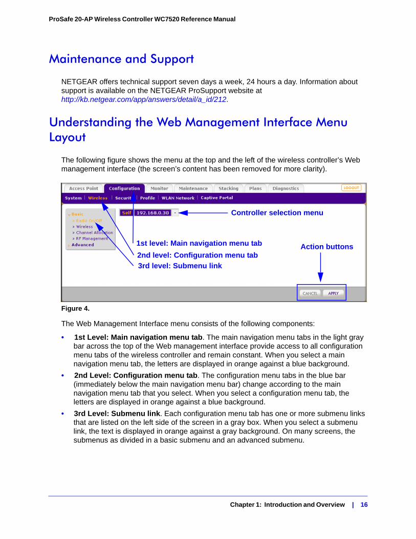
The following figure shows the menu at the top and the left of the wireless controller’s Web management interface (the screen’s content has been removed for more clarity).
Figure 4.
The Web Management Interface menu consists of the following components:
• 1st Level: Main navigation menu tab. The main navigation menu tabs in the light gray bar across the top of the Web management interface provide access to all configuration menu tabs of the wireless controller and remain constant. When you select a main navigation menu tab, the letters are displayed in orange against a blue background.
• 2nd Level: Configuration menu tab. The configuration menu tabs in the blue bar (immediately below the main navigation menu bar) change according to the main navigation menu tab that you select. When you select a configuration menu tab, the letters are displayed in orange against a blue background.
• 3rd Level: Submenu link. Each configuration menu tab has one or more submenu links that are listed on the left side of the screen in a gray box. When you select a submenu link, the text is displayed in orange against a gray background. On many screens, the submenus as divided in a basic submenu and an advanced submenu.
1st level: Main navigation menu tab
2nd level: Configuration menu tab
3rd level: Submenu link
Action buttons
Controller selection menu
Chapter 1: Introduction and Overview | 16
ProSafe 20-AP Wireless Controller WC7520 Reference Manual
• Action buttons. Action buttons change the configuration or allow you to make changes to the configuration. These are the most common action buttons:
- Apply. Saves all configuration changes made on the current screen. Saved settings are retained when the wireless controller is powered off or rebooted while unsaved configuration changes are lost.
- Cancel. Resets options on the current screen to the last-applied or saved settings.
- Add. Adds a new item to the current screen. Typically, a popup screen opens that enables you to enter information in additional fields.
- Edit. Allows you to edit the configuration of the selected item.
- Remove or Delete. Removes the selected item from the table or screen configuration.
- Back. Return to the previous screen.
- Next. Advance to the next screen.
• Controller selection menu. In a stacked configuration, the controller selection menu lets you select the wireless controller to configure.
Initial Connection and Configuration
Follow the steps in this section to set up the wireless controller. For additional information, see the WC7520 ProSafe Wireless Controller Installation Guide at http://kb.netgear.com/app/products/model/a_id/13060.
To set up, configure, and deploy the wireless controller:
1. Connect the wireless controller to your computer:
a. Configure a computer with a static IP address of 192.168.0.210 and 255.255.255.0 as the subnet mask.
b. Connect the wireless controller to the computer via the network or directly to one of the wireless controller’s ports.
c. Connect the power cord from the wireless controller to an AC power outlet.
d. Check the lights on the front of the wireless controller:
• Power. The green power light should be lit. If the power light is not lit, check the connections and check to see if the power outlet is controlled by a wall switch that is turned off.
• Test. The Test light is on briefly when the controller is first turned on.
• LAN The Ethernet (LAN) light should be lit (amber for 10/100 Mbps and green for 1000 Mbps) indicating that a connection has been made. If not, make sure the Ethernet cable is securely attached at both ends.
Chapter 1: Introduction and Overview | 17
ProSafe 20-AP Wireless Controller WC7520 Reference Manual
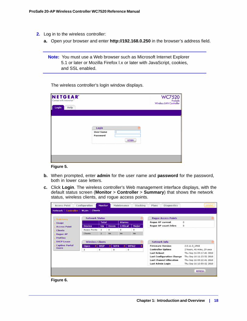
2. Log in to the wireless controller:
a. Open your browser and enter http://192.168.0.250 in the browser’s address field.
Note: You must use a Web browser such as Microsoft Internet Explorer 5.1 or later or Mozilla Firefox l.x or later with JavaScript, cookies, and SSL enabled.
The wireless controller’s login window displays.
Figure 5.
b. When prompted, enter admin for the user name and password for the password, both in lower case letters.
c. Click Login. The wireless controller’s Web management interface displays, with the default status screen (Monitor > Controller > Summary) that shows the network status, wireless clients, and rogue access points.
Figure 6.
Chapter 1: Introduction and Overview | 18
ProSafe 20-AP Wireless Controller WC7520 Reference Manual
For information about the layout and general characteristics of the Web management interface, see Understanding the Web Management Interface Menu Layout on page 16.
3. Configure the wireless controller and your network:
a. RF planning. Follow instructions in Chapter 3, RF Planning to plan the number and location of the access points.
b. Configure your network. Follow the instructions in Chapter 4 through to Chapter 10 to configure your network, including the SSIDs, security, MAC ACLs, captive portal, QoS, rate limiting, and so on.
c. Set up the wireless controller. Follow the instructions in System Planning on page 22 to select the type of deployment for your network.
d. Add the access points. Follow the steps in Access Point Discovery on page 46 to discover your access points and add them to wireless controller’s managed access point list.
Understanding Basic and Advanced Settings
You can deploy the wireless controller in a small wireless network with 10 or 20 access points or in a large wireless network with up to 150 access points. Small networks require a basic configuration but large networks can become very complex and require you to configure the advanced features of the wireless controller.
Depending on your network configuration, use basic settings or advanced settings to manage your access points:
• Basic settings for a typical network. The basic settings work with the most common network configuration. For example, all access points on the WLAN are for the same organization or business and therefore adhere to the same policies and use a small number of service set identifiers (SSIDs, or network names).
• Advanced settings for access point groups. If you have a large wireless network, or if completely separate networks share a single WLAN, use the advanced settings to set up multiple access point profile groups and multiple security profiles (SSIDs). For example, a shopping mall might need several access point profile groups if several businesses share a WLAN but each business has its own network. Larger networks could require multiple access point profile groups to allow different policies per building or department. The access points could have different SSIDs per building and department, for example, one for guests, one for management, one for sales, and so on.
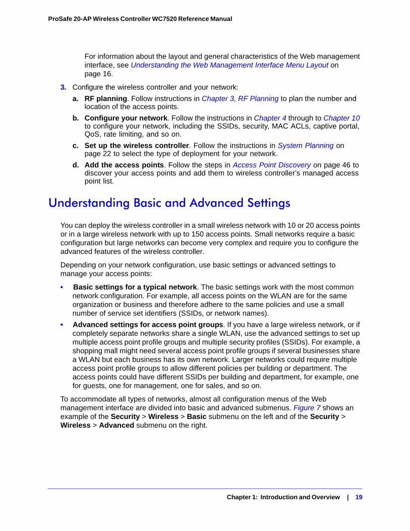
To accommodate all types of networks, almost all configuration menus of the Web management interface are divided into basic and advanced submenus. Figure 7 shows an example of the Security > Wireless > Basic submenu on the left and of the Security > Wireless > Advanced submenu on the right.
Chapter 1: Introduction and Overview | 19
ProSafe 20-AP Wireless Controller WC7520 Reference Manual
Figure 7.
One of the advanced features of the wireless controller is the capability to create multiple access point profile groups. Each access point operates using one profile group. The default profile group is called ‘basic.’ A profile group includes all the features that you can configure for an individual access point, including up to 8 SSIDs, security, QoS, load balancing, and so on. For a basic configuration, the default profile group applies to all access points that are controlled by the wireless controller.
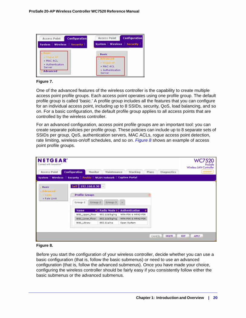
For an advanced configuration, access point profile groups are an important tool: you can create separate policies per profile group. These policies can include up to 8 separate sets of SSIDs per group, QoS, authentication servers, MAC ACLs, rogue access point detection, rate limiting, wireless-on/off schedules, and so on. Figure 8 shows an example of access point profile groups.
Figure 8.
Before you start the configuration of your wireless controller, decide whether you can use a basic configuration (that is, follow the basic submenus) or need to use an advanced configuration (that is, follow the advanced submenus). Once you have made your choice, configuring the wireless controller should be fairly easy if you consistently follow either the basic submenus or the advanced submenus.
Chapter 1: Introduction and Overview | 20
ProSafe 20-AP Wireless Controller WC7520 Reference Manual
Choosing a Location for the Wireless Controller
The wireless controller is suitable for use in an office environment where it can be freestanding on its runner feet or mounted into a standard 19-inch equipment rack. Alternatively, you can rack-mount the wireless controller in a wiring closet or equipment room. A mounting kit, containing two mounting brackets and screws is provided in the wireless controller package.
Consider the following when deciding where to position the wireless controller:
• The unit is accessible and cables can be connected easily.
• Cabling is away from sources of electrical noise. These include lift shafts, microwave ovens, and air-conditioning units.
• Water or moisture cannot enter the case of the unit.
• Airflow around the unit and through the vents in the side of the case is not restricted. Provide a minimum of 25 mm or 1 inch clearance.
• The air is as free of dust as possible.
• Temperature operating limits are not likely to be exceeded. Install the unit in a clean, air-conditioned environment. For information about the recommended operating temperatures for the wireless controller, see Factory Default Settings and Technical Specifications in Appendix A.
Deploying the Wireless Controller
To deploy the wireless controller:
1. Disconnect the wireless controller from the computer and place it where you will deploy it. If needed, you can now reconfigure the computer that you used in the configuration process back to its original TCP/IP settings.
2. Connect an Ethernet cable from your wireless controller to a LAN port on your network.
3. Connect the power cord to the wireless controller and plug the power cord into a power outlet. The Power, Test, and Ethernet LEDs should light up. If any of these do not light up, see Troubleshooting Basic Functioning on page 144.
Chapter 1: Introduction and Overview | 21
2. System Planning and Deployment Scenarios 2
This chapter includes the following sections:• System Planning on this page
• Management VLAN and Data VLAN Strategies on page 27
• Deployment Scenarios on page 29
System Planning
This section includes the following subsections:
• Pre-Installation Planning on this page
• Before You Configure a Wireless Controller on page 23
• Single Controller Configuration with Basic Profile Group on page 25
• Single Controller Configuration with Access Point Groups on page 26
• Stacked Controller Configuration on page 27
Pre-Installation PlanningBefore you install any wireless controllers, determine the following:
• Number of access points required to provide seamless coverage
• Number of wireless controllers required
• 802.11 frequency band and the channels that are optimal for Wi-Fi usage
NETGEAR recommends that you perform a site survey:
• Run a spectrum analysis of channels of the site to determine the current RF behavior and detect both 802.11 and non-802.11 noise.
• Run an access point-to-client connectivity test to determine the maximum throughput achievable on the client.
• Identify potential RF obstructions and interference sources.
• Determine areas where denser coverage might be required because of heavier usage.
Chapter 2: System Planning and Deployment Scenarios | 22
ProSafe 20-AP Wireless Controller WC7520 Reference Manual
After the survey is complete, use the collected data to set up an RF plan. For more information, see RF Planning Overview on page 36.
Before You Configure a Wireless ControllerThese sections assume that you have deployed at least one wireless controller in your network and are ready to configure the wireless controller. For information about how to deploy the wireless controller in your network, see the WC7520 ProSafe Wireless Controller Installation Guide at http://kb.netgear.com/app/products/model/a_id/13060.
For many configurations, you can use the wireless default settings. The IP address, VLAN, DHCP server, client authentication and data encryption settings are specific to your environment. Following are short sections that discuss these settings (with the exception of IP address settings, which are self explanatory). For information about how to configure these settings, see the links to the chapters.
VLANs
Management VLAN
The management VLAN is the dedicated VLAN for access to the wireless controller. All traffic that is directed to the wireless controller, including HTTP, HTTPS, SNMP, and SSH traffic, is carried over the management VLAN.
If the management VLAN is also configured as a tagged VLAN (the most common configuration), the packets to and from the wireless controller carry the 802.1Q VLAN header with the assigned VLAN number. If the management VLAN is marked as untagged, the packets that are sent from the wireless controller do not carry the 802.1Q header, and all untagged packets that are sent to the wireless controller are treated as management VLAN traffic.
Note: Use a tagged VLAN or change the tagged VLAN ID only if the hubs and switches on your LAN support 802.1Q. If they do not, and you have not specifically configured a tagged VLAN with the same VLAN ID on the hubs and switches in your network, IP connectivity might be lost.
The wireless controller must have IP connectivity with the access points through the management VLAN. If the wireless controller and the access points are on different management VLANs, external VLAN routing must allow IP connectivity between the wireless controller and the access points.
For information about how to configure management VLANs, see Configuring IP and VLAN Settings on page 57.
Chapter 2: System Planning and Deployment Scenarios | 23
ProSafe 20-AP Wireless Controller WC7520 Reference Manual
Client VLANs
Each authenticated wireless user is placed into a VLAN that determines the user’s DHCP server, IP address, and layer 2 connection. Although you could place all authenticated wireless users into the single VLAN that is specified in the basic security profile, the wireless controller allows you to group wireless users into separate VLANs based on the wireless SSID to differentiate access to network resources. For example, you might place authorized employee users into one VLAN and itinerant users, such as contractors or guests, into a separate VLAN. To use different VLANs, you must create different security profiles.
For information about how to configure regular VLANs, see Managing Wireless Security Profiles on page 83.
DHCP ServerThe wireless controller can function as a DHCP server and assign IP addresses to both wireless and wired devices that are connected to it. You can add up to 64 DHCP server pools, each assigned to a different VLAN.
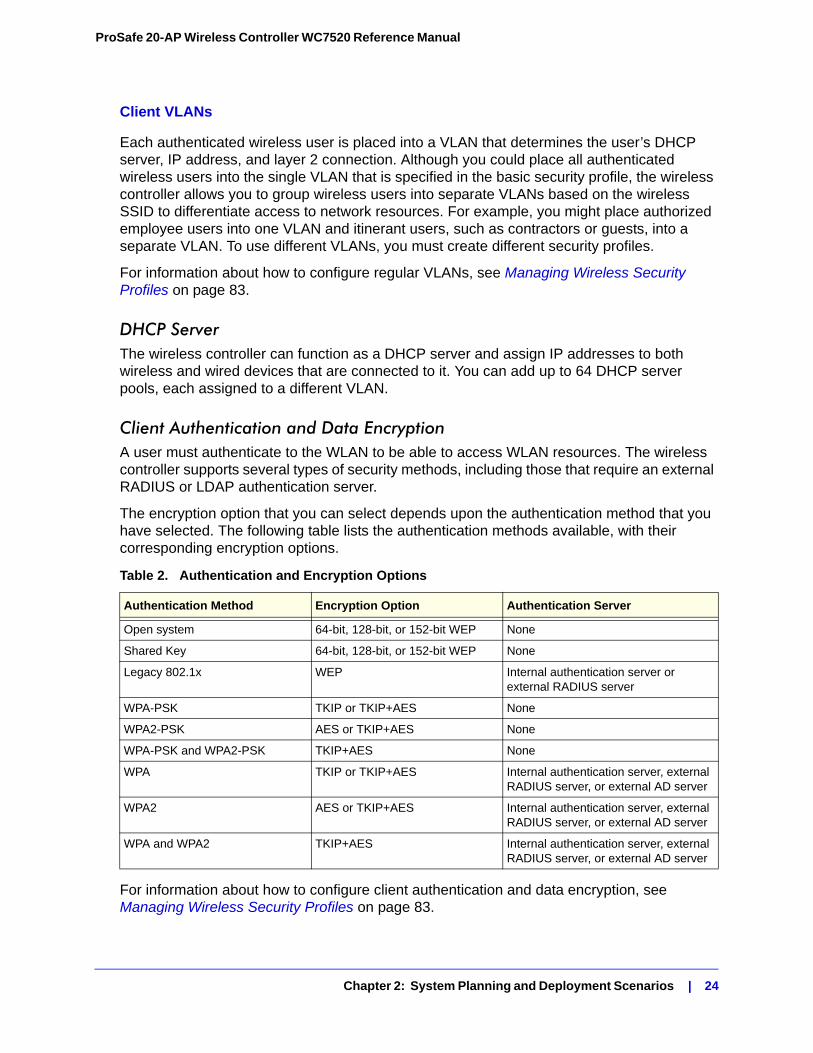
Client Authentication and Data EncryptionA user must authenticate to the WLAN to be able to access WLAN resources. The wireless controller supports several types of security methods, including those that require an external RADIUS or LDAP authentication server.
The encryption option that you can select depends upon the authentication method that you have selected. The following table lists the authentication methods available, with their corresponding encryption options.
For information about how to configure client authentication and data encryption, see Managing Wireless Security Profiles on page 83.
Table 2. Authentication and Encryption Options
Authentication Method Encryption Option Authentication Server
Open system 64-bit, 128-bit, or 152-bit WEP None
Shared Key 64-bit, 128-bit, or 152-bit WEP None
Legacy 802.1x WEP Internal authentication server or external RADIUS server
WPA-PSK TKIP or TKIP+AES None
WPA2-PSK AES or TKIP+AES None
WPA-PSK and WPA2-PSK TKIP+AES None
WPA TKIP or TKIP+AES Internal authentication server, external RADIUS server, or external AD server
WPA2 AES or TKIP+AES Internal authentication server, external RADIUS server, or external AD server
WPA and WPA2 TKIP+AES Internal authentication server, external RADIUS server, or external AD server
Chapter 2: System Planning and Deployment Scenarios | 24
ProSafe 20-AP Wireless Controller WC7520 Reference Manual
For information about how to configure authentication servers, see Managing Authentication Servers and Authentication Server Groups on page 95.
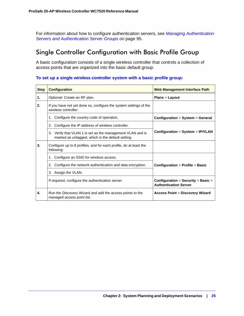
Single Controller Configuration with Basic Profile GroupA basic configuration consists of a single wireless controller that controls a collection of access points that are organized into the basic default group.
To set up a single wireless controller system with a basic profile group:
Step Configuration Web Management Interface Path
1. Optional: Create an RF plan. Plans > Layout
2. If you have not yet done so, configure the system settings of the wireless controller:
1. Configure the country code of operation. Configuration > System > General
2. Configure the IP address of wireless controller.
Configuration > System > IP/VLAN3. Verify that VLAN 1 is set as the management VLAN and is marked as untagged, which is the default setting.
3. Configure up to 8 profiles, and for each profile, do at least the following:
1. Configure an SSID for wireless access.
Configuration > Profile > Basic2. Configure the network authentication and data encryption.
3. Assign the VLAN.
If required, configure the authentication server. Configuration > Security > Basic > Authentication Server
4. Run the Discovery Wizard and add the access points to the managed access point list.
Access Point > Discovery Wizard
Chapter 2: System Planning and Deployment Scenarios | 25
ProSafe 20-AP Wireless Controller WC7520 Reference Manual
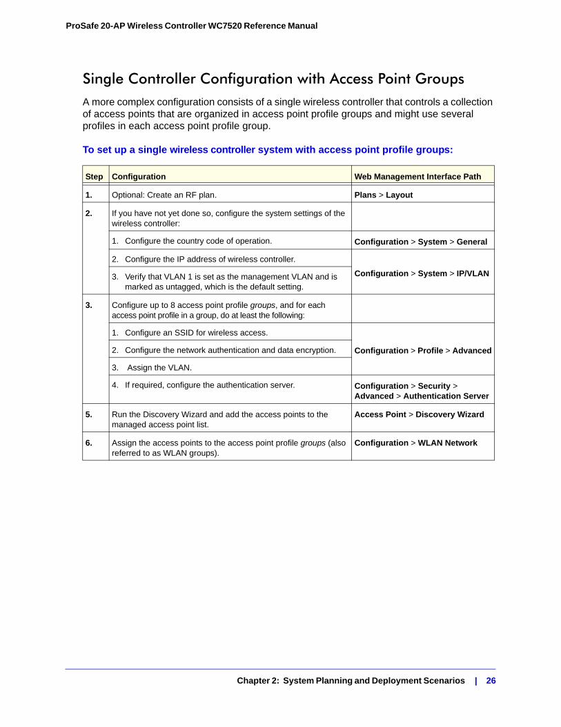
Single Controller Configuration with Access Point GroupsA more complex configuration consists of a single wireless controller that controls a collection of access points that are organized in access point profile groups and might use several profiles in each access point profile group.
To set up a single wireless controller system with access point profile groups:
Step Configuration Web Management Interface Path
1. Optional: Create an RF plan. Plans > Layout
2. If you have not yet done so, configure the system settings of the wireless controller:
1. Configure the country code of operation. Configuration > System > General
2. Configure the IP address of wireless controller.
Configuration > System > IP/VLAN3. Verify that VLAN 1 is set as the management VLAN and is marked as untagged, which is the default setting.
3. Configure up to 8 access point profile groups, and for each access point profile in a group, do at least the following:
1. Configure an SSID for wireless access.
Configuration > Profile > Advanced2. Configure the network authentication and data encryption.
3. Assign the VLAN.
4. If required, configure the authentication server. Configuration > Security > Advanced > Authentication Server
5. Run the Discovery Wizard and add the access points to the managed access point list.
Access Point > Discovery Wizard
6. Assign the access points to the access point profile groups (also referred to as WLAN groups).
Configuration > WLAN Network
Chapter 2: System Planning and Deployment Scenarios | 26
ProSafe 20-AP Wireless Controller WC7520 Reference Manual
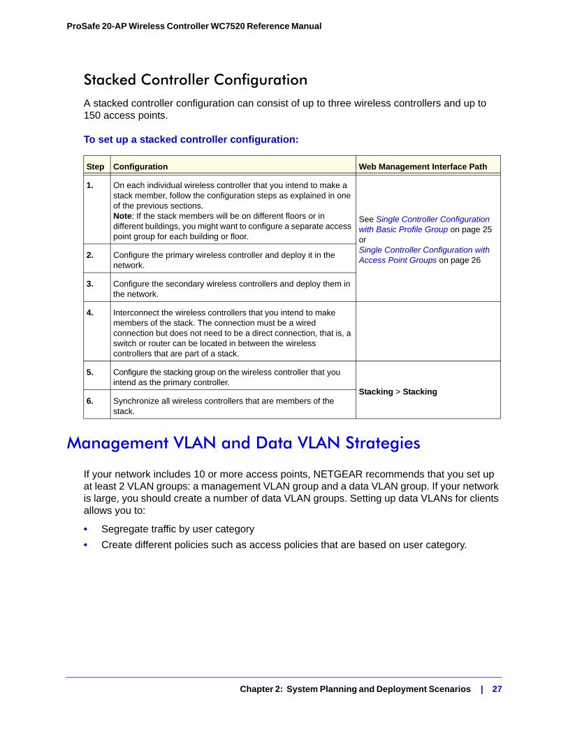
Stacked Controller ConfigurationA stacked controller configuration can consist of up to three wireless controllers and up to 150 access points.
To set up a stacked controller configuration:
Management VLAN and Data VLAN Strategies
If your network includes 10 or more access points, NETGEAR recommends that you set up at least 2 VLAN groups: a management VLAN group and a data VLAN group. If your network is large, you should create a number of data VLAN groups. Setting up data VLANs for clients allows you to:
• Segregate traffic by user category
• Create different policies such as access policies that are based on user category.
Step Configuration Web Management Interface Path
1. On each individual wireless controller that you intend to make a stack member, follow the configuration steps as explained in one of the previous sections. Note: If the stack members will be on different floors or in different buildings, you might want to configure a separate access point group for each building or floor.
See Single Controller Configuration with Basic Profile Group on page 25 or Single Controller Configuration with Access Point Groups on page 26
2. Configure the primary wireless controller and deploy it in the network.
3. Configure the secondary wireless controllers and deploy them in the network.
4. Interconnect the wireless controllers that you intend to make members of the stack. The connection must be a wired connection but does not need to be a direct connection, that is, a switch or router can be located in between the wireless controllers that are part of a stack.
5. Configure the stacking group on the wireless controller that you intend as the primary controller.
Stacking > Stacking6. Synchronize all wireless controllers that are members of the
stack.
Chapter 2: System Planning and Deployment Scenarios | 27
ProSafe 20-AP Wireless Controller WC7520 Reference Manual
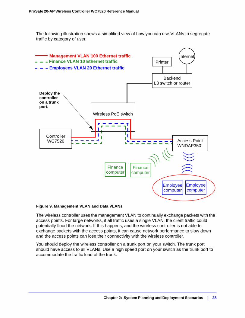
The following illustration shows a simplified view of how you can use VLANs to segregate traffic by category of user.
Figure 9. Management VLAN and Data VLANs
The wireless controller uses the management VLAN to continually exchange packets with the access points. For large networks, if all traffic uses a single VLAN, the client traffic could potentially flood the network. If this happens, and the wireless controller is not able to exchange packets with the access points, it can cause network performance to slow down and the access points can lose their connectivity with the wireless controller.
You should deploy the wireless controller on a trunk port on your switch. The trunk port should have access to all VLANs. Use a high speed port on your switch as the trunk port to accommodate the traffic load of the trunk.
Backend
Access PointWNDAP350
L3 switch or router
Wireless PoE switch
ControllerWC7520
Finance VLAN 10 Ethernet trafficManagement VLAN 100 Ethernet traffic
Employees VLAN 20 Ethernet traffic
Financecomputer
Financecomputer
Employeecomputer
Employeecomputer
PrinterInternet
Deploy thecontroller on a trunkport.
Chapter 2: System Planning and Deployment Scenarios | 28
ProSafe 20-AP Wireless Controller WC7520 Reference Manual
Deployment Scenarios
This section provides three deployment scenarios to illustrate how the wireless controller can function in a variety of network configurations:
• Scenario Example 1: Basic Network with Single VLAN on this page
• Scenario Example 2: Advanced Network with VLANs and SSIDs on page 31
• Scenario Example 3: Advanced Network With Redundancy on page 33
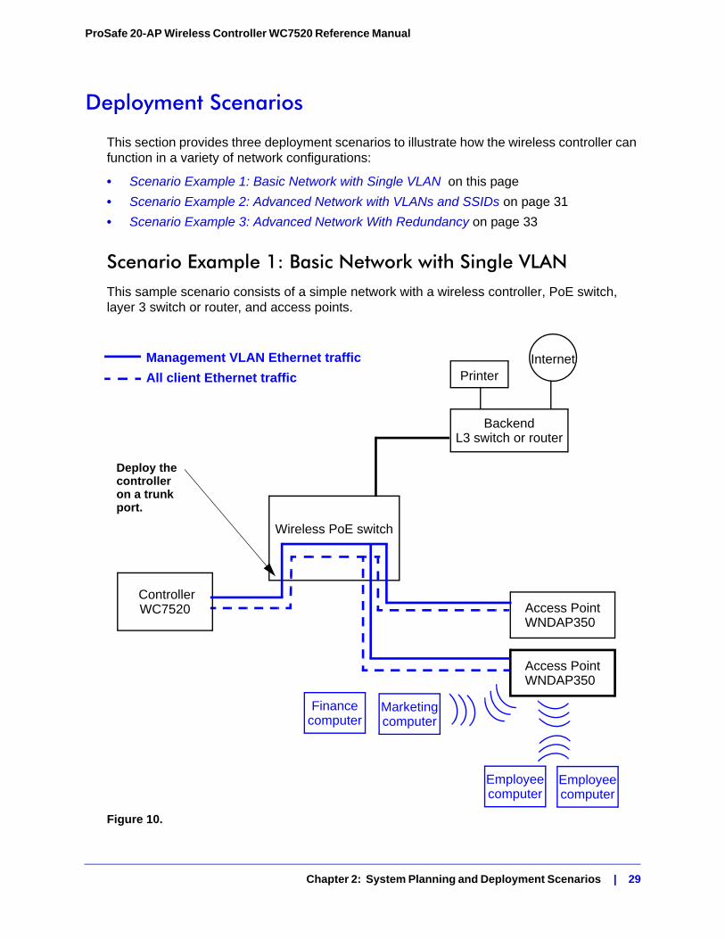
Scenario Example 1: Basic Network with Single VLANThis sample scenario consists of a simple network with a wireless controller, PoE switch, layer 3 switch or router, and access points.
Figure 10.
Backend
Access PointWNDAP350
L3 switch or router
Wireless PoE switch
ControllerWC7520
Management VLAN Ethernet traffic
All client Ethernet traffic
Employeecomputer
Employeecomputer
PrinterInternet
Deploy thecontroller on a trunkport.
Access PointWNDAP350
Financecomputer
Marketingcomputer
Chapter 2: System Planning and Deployment Scenarios | 29
ProSafe 20-AP Wireless Controller WC7520 Reference Manual
The access points and wireless controller are connected in the same subnet and use the same IP address range that is assigned for that subnet. There are no routers in between the access points and the wireless controller. The access points are connected to a PoE switch, which, in turn, is connected to the wireless controller. The uplink of PoE switch connects to a layer 3 switch or router that provides Internet access.
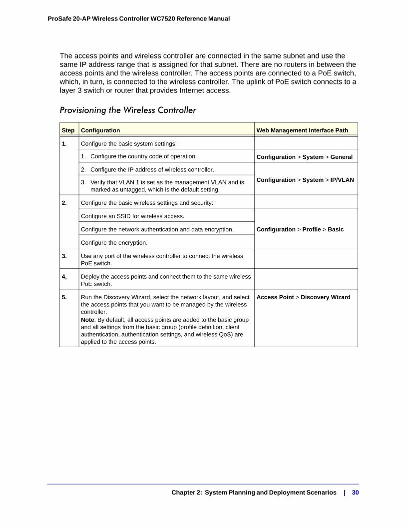
Provisioning the Wireless Controller
Step Configuration Web Management Interface Path
1. Configure the basic system settings:
1. Configure the country code of operation. Configuration > System > General
2. Configure the IP address of wireless controller.
Configuration > System > IP/VLAN3. Verify that VLAN 1 is set as the management VLAN and is marked as untagged, which is the default setting.
2. Configure the basic wireless settings and security:
Configure an SSID for wireless access.
Configuration > Profile > BasicConfigure the network authentication and data encryption.
Configure the encryption.
3. Use any port of the wireless controller to connect the wireless PoE switch.
4, Deploy the access points and connect them to the same wireless PoE switch.
5. Run the Discovery Wizard, select the network layout, and select the access points that you want to be managed by the wireless controller.Note: By default, all access points are added to the basic group and all settings from the basic group (profile definition, client authentication, authentication settings, and wireless QoS) are applied to the access points.
Access Point > Discovery Wizard
Chapter 2: System Planning and Deployment Scenarios | 30
ProSafe 20-AP Wireless Controller WC7520 Reference Manual
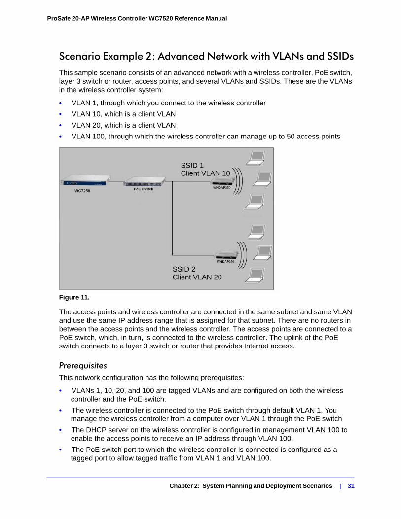
Scenario Example 2: Advanced Network with VLANs and SSIDsThis sample scenario consists of an advanced network with a wireless controller, PoE switch, layer 3 switch or router, access points, and several VLANs and SSIDs. These are the VLANs in the wireless controller system:
• VLAN 1, through which you connect to the wireless controller
• VLAN 10, which is a client VLAN
• VLAN 20, which is a client VLAN
• VLAN 100, through which the wireless controller can manage up to 50 access points
Figure 11.
The access points and wireless controller are connected in the same subnet and same VLAN and use the same IP address range that is assigned for that subnet. There are no routers in between the access points and the wireless controller. The access points are connected to a PoE switch, which, in turn, is connected to the wireless controller. The uplink of the PoE switch connects to a layer 3 switch or router that provides Internet access.
PrerequisitesThis network configuration has the following prerequisites:
• VLANs 1, 10, 20, and 100 are tagged VLANs and are configured on both the wireless controller and the PoE switch.
• The wireless controller is connected to the PoE switch through default VLAN 1. You manage the wireless controller from a computer over VLAN 1 through the PoE switch
• The DHCP server on the wireless controller is configured in management VLAN 100 to enable the access points to receive an IP address through VLAN 100.
• The PoE switch port to which the wireless controller is connected is configured as a tagged port to allow tagged traffic from VLAN 1 and VLAN 100.
SSID 2Client VLAN 20
SSID 1Client VLAN 10
Chapter 2: System Planning and Deployment Scenarios | 31
ProSafe 20-AP Wireless Controller WC7520 Reference Manual
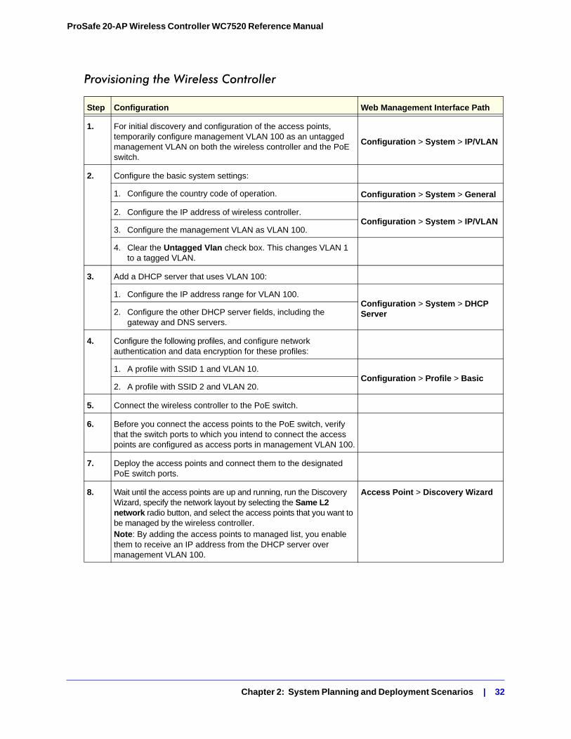
Provisioning the Wireless Controller
Step Configuration Web Management Interface Path
1. For initial discovery and configuration of the access points, temporarily configure management VLAN 100 as an untagged management VLAN on both the wireless controller and the PoE switch.
Configuration > System > IP/VLAN
2. Configure the basic system settings:
1. Configure the country code of operation. Configuration > System > General
2. Configure the IP address of wireless controller.Configuration > System > IP/VLAN
3. Configure the management VLAN as VLAN 100.
4. Clear the Untagged Vlan check box. This changes VLAN 1 to a tagged VLAN.
3. Add a DHCP server that uses VLAN 100:
1. Configure the IP address range for VLAN 100.Configuration > System > DHCP Server2. Configure the other DHCP server fields, including the
gateway and DNS servers.
4. Configure the following profiles, and configure network authentication and data encryption for these profiles:
1. A profile with SSID 1 and VLAN 10.Configuration > Profile > Basic
2. A profile with SSID 2 and VLAN 20.
5. Connect the wireless controller to the PoE switch.
6. Before you connect the access points to the PoE switch, verify that the switch ports to which you intend to connect the access points are configured as access ports in management VLAN 100.
7. Deploy the access points and connect them to the designated PoE switch ports.
8. Wait until the access points are up and running, run the Discovery Wizard, specify the network layout by selecting the Same L2 network radio button, and select the access points that you want to be managed by the wireless controller.Note: By adding the access points to managed list, you enable them to receive an IP address from the DHCP server over management VLAN 100.
Access Point > Discovery Wizard
Chapter 2: System Planning and Deployment Scenarios | 32
ProSafe 20-AP Wireless Controller WC7520 Reference Manual
Scenario Example 3: Advanced Network With RedundancyThis sample scenario consists of an advanced network with one wireless controller, one redundant wireless controller, one core switch, two PoE switches in different buildings, access points, and several VLANs and SSIDs. These are the components in the wireless controller system:
• One wireless controller
• 50 access points (managed by the wireless controller through management VLAN 1)
• One redundant wireless controller
• Four VLANs: VLAN 10, VLAN 20, VLAN 30, and VLAN 40
• Three SSIDs: SSID 1, SSID 2, and SSID 3
In this scenario, the VLANs and SSIDs are used to accommodate traffic for different user groups in a school that is spread out over two buildings
• Building 1:
- SSID 1 in VLAN 10 for staff traffic
- SSID 2 in VLAN 20 for middle school students
- SSID 3 in VLAN 30 for guests
• Building 2:
- SSID 1 in VLAN 10 for staff traffic
- SSID 2 in VLAN 40 for high school students
- SSID 3 in VLAN 30 for guests
9. For each access point on the managed list, clear the Untagged Vlan check box and configure VLAN 100 as the management VLAN. Doing so causes the access points to lose connectivity with the wireless controller.
10. Restore connectivity between the access points and the wireless controller by changing the PoE switch ports to which the access points are connected to tagged ports. (During the discovery process, these switch ports were access ports in management VLAN 100.)
Step Configuration Web Management Interface Path
Chapter 2: System Planning and Deployment Scenarios | 33
ProSafe 20-AP Wireless Controller WC7520 Reference Manual
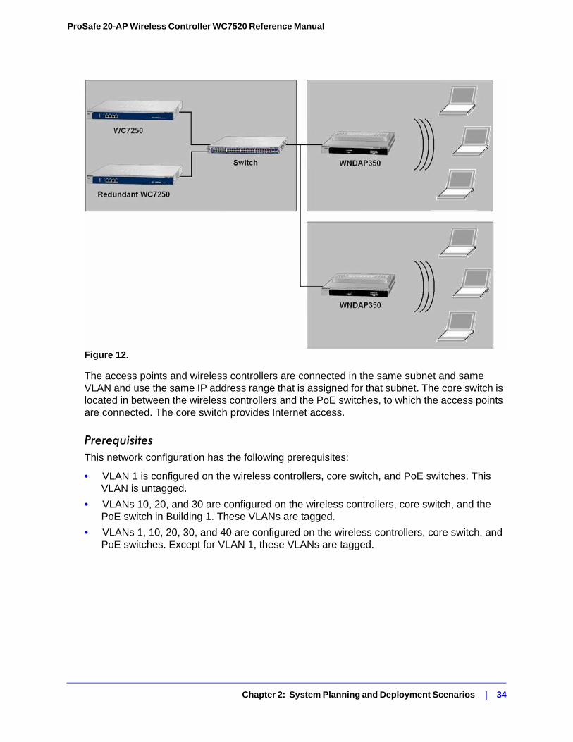
Figure 12.
The access points and wireless controllers are connected in the same subnet and same VLAN and use the same IP address range that is assigned for that subnet. The core switch is located in between the wireless controllers and the PoE switches, to which the access points are connected. The core switch provides Internet access.
PrerequisitesThis network configuration has the following prerequisites:
• VLAN 1 is configured on the wireless controllers, core switch, and PoE switches. This VLAN is untagged.
• VLANs 10, 20, and 30 are configured on the wireless controllers, core switch, and the PoE switch in Building 1. These VLANs are tagged.
• VLANs 1, 10, 20, 30, and 40 are configured on the wireless controllers, core switch, and PoE switches. Except for VLAN 1, these VLANs are tagged.
Chapter 2: System Planning and Deployment Scenarios | 34
ProSafe 20-AP Wireless Controller WC7520 Reference Manual
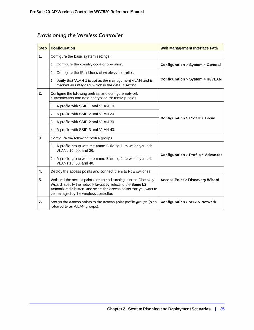
Provisioning the Wireless Controller
Step Configuration Web Management Interface Path
1. Configure the basic system settings:
1. Configure the country code of operation. Configuration > System > General
2. Configure the IP address of wireless controller.
Configuration > System > IP/VLAN3. Verify that VLAN 1 is set as the management VLAN and is marked as untagged, which is the default setting.
2. Configure the following profiles, and configure network authentication and data encryption for these profiles:
1. A profile with SSID 1 and VLAN 10.
Configuration > Profile > Basic2. A profile with SSID 2 and VLAN 20.
3. A profile with SSID 2 and VLAN 30.
4. A profile with SSID 3 and VLAN 40.
3. Configure the following profile groups
1. A profile group with the name Building 1, to which you add VLANs 10, 20, and 30.
Configuration > Profile > Advanced2. A profile group with the name Building 2, to which you add
VLANs 10, 30, and 40.
4. Deploy the access points and connect them to PoE switches.
5. Wait until the access points are up and running, run the Discovery Wizard, specify the network layout by selecting the Same L2 network radio button, and select the access points that you want to be managed by the wireless controller.
Access Point > Discovery Wizard
7. Assign the access points to the access point profile groups (also referred to as WLAN groups).
Configuration > WLAN Network
Chapter 2: System Planning and Deployment Scenarios | 35
3. RF Planning 3
This chapter includes the following sections:• RF Planning Overview on this page
• Defining and Editing Buildings and Floors on page 38
• Specifying Access Point Requirements on page 40
• Viewing and Managing Heat Maps for Deployed Plans on page 42
RF Planning Overview
You can do the following with RF planning:
• Define WLAN coverage.
• Estimate the number of access points required based on signal quality and number of clients per access point.
• Optimize the placement of access points for the best coverage.
• Monitor WLAN coverage, rogue access points, and blacklisted clients for a plan that is in deployment.
• Identify weak signal spots and dead spots from the coverage hole and add additional access points to mitigate the situation.
RF planning provides a view of each floor, allowing you to specify how Wi-Fi coverage should be provided. It then provides coverage maps and access point placement locations. Real-time calibration lets you visualize the indoor propagation of RF signals to identify areas with weak signal or dead spots and add additional access points in the right location to mitigate the weak signal or dead spots.
Chapter 3: RF Planning | 36
ProSafe 20-AP Wireless Controller WC7520 Reference Manual
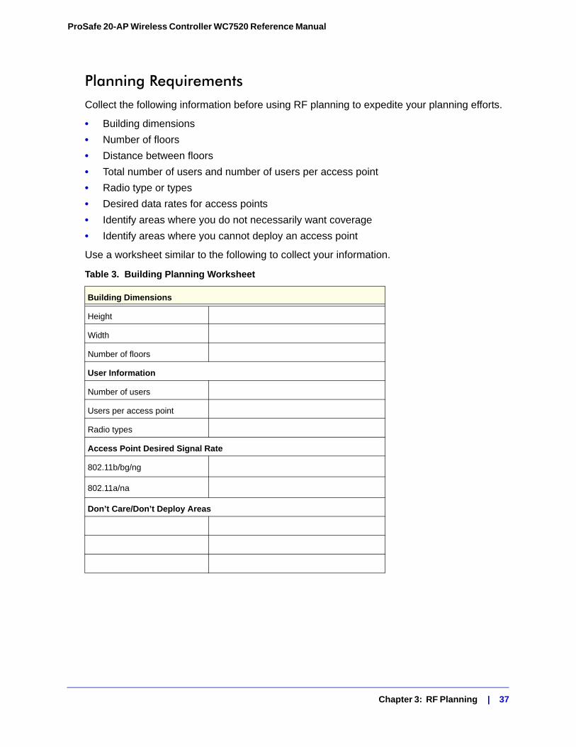
Planning RequirementsCollect the following information before using RF planning to expedite your planning efforts.
• Building dimensions
• Number of floors
• Distance between floors
• Total number of users and number of users per access point
• Radio type or types
• Desired data rates for access points
• Identify areas where you do not necessarily want coverage
• Identify areas where you cannot deploy an access point
Use a worksheet similar to the following to collect your information.
Table 3. Building Planning Worksheet
Building Dimensions
Height
Width
Number of floors
User Information
Number of users
Users per access point
Radio types
Access Point Desired Signal Rate
802.11b/bg/ng
802.11a/na
Don’t Care/Don’t Deploy Areas
Chapter 3: RF Planning | 37
ProSafe 20-AP Wireless Controller WC7520 Reference Manual
Defining and Editing Buildings and Floors
This section explains how you can define your buildings and floors, and make modifications after you have defined them. You can add a maximum of three buildings.
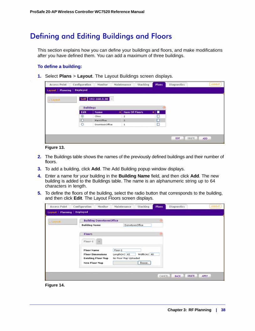
To define a building:
1. Select Plans > Layout. The Layout Buildings screen displays..
Figure 13.
2. The Buildings table shows the names of the previously defined buildings and their number of floors.
3. To add a building, click Add. The Add Building popup window displays.
4. Enter a name for your building in the Building Name field, and then click Add. The new building is added to the Buildings table. The name is an alphanumeric string up to 64 characters in length.
5. To define the floors of the building, select the radio button that corresponds to the building, and then click Edit. The Layout Floors screen displays.
Figure 14.
Chapter 3: RF Planning | 38
ProSafe 20-AP Wireless Controller WC7520 Reference Manual
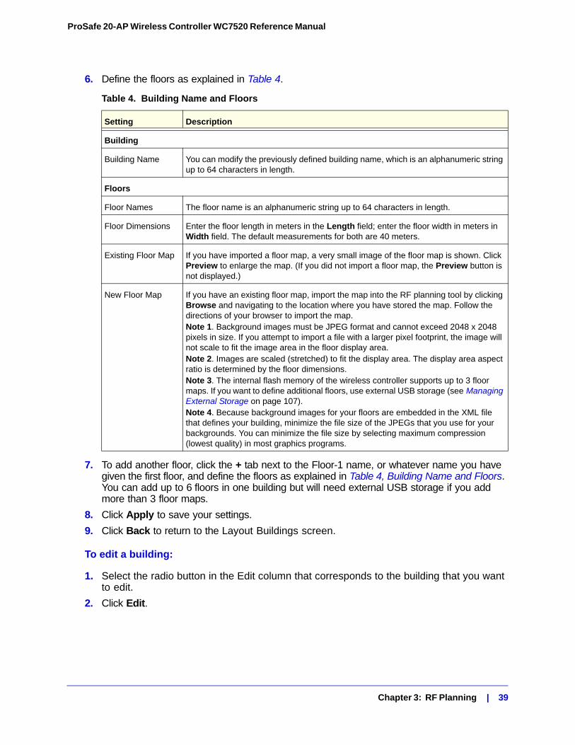
6. Define the floors as explained in Table 4.
7. To add another floor, click the + tab next to the Floor-1 name, or whatever name you have given the first floor, and define the floors as explained in Table 4, Building Name and Floors. You can add up to 6 floors in one building but will need external USB storage if you add more than 3 floor maps.
8. Click Apply to save your settings.
9. Click Back to return to the Layout Buildings screen.
To edit a building:
1. Select the radio button in the Edit column that corresponds to the building that you want to edit.
2. Click Edit.
Table 4. Building Name and Floors
Setting Description
Building
Building Name You can modify the previously defined building name, which is an alphanumeric string up to 64 characters in length.
Floors
Floor Names The floor name is an alphanumeric string up to 64 characters in length.
Floor Dimensions Enter the floor length in meters in the Length field; enter the floor width in meters in Width field. The default measurements for both are 40 meters.
Existing Floor Map If you have imported a floor map, a very small image of the floor map is shown. Click Preview to enlarge the map. (If you did not import a floor map, the Preview button is not displayed.)
New Floor Map If you have an existing floor map, import the map into the RF planning tool by clicking Browse and navigating to the location where you have stored the map. Follow the directions of your browser to import the map.Note 1. Background images must be JPEG format and cannot exceed 2048 x 2048 pixels in size. If you attempt to import a file with a larger pixel footprint, the image will not scale to fit the image area in the floor display area.Note 2. Images are scaled (stretched) to fit the display area. The display area aspect ratio is determined by the floor dimensions.Note 3. The internal flash memory of the wireless controller supports up to 3 floor maps. If you want to define additional floors, use external USB storage (see Managing External Storage on page 107).Note 4. Because background images for your floors are embedded in the XML file that defines your building, minimize the file size of the JPEGs that you use for your backgrounds. You can minimize the file size by selecting maximum compression (lowest quality) in most graphics programs.
Chapter 3: RF Planning | 39
ProSafe 20-AP Wireless Controller WC7520 Reference Manual
To delete a building:
1. Select the check box that corresponds to the building that you want to delete, or select the check box at the top row of the table to delete all buildings.
2. Click Delete.
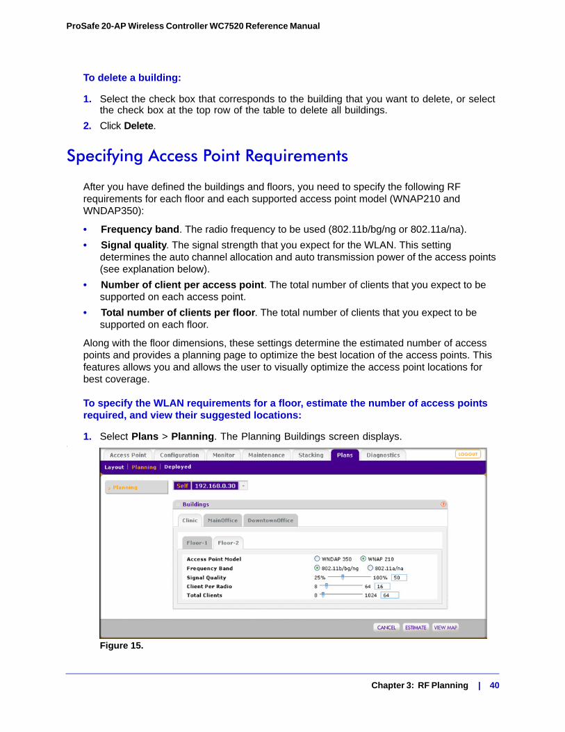
Specifying Access Point Requirements
After you have defined the buildings and floors, you need to specify the following RF requirements for each floor and each supported access point model (WNAP210 and WNDAP350):
• Frequency band. The radio frequency to be used (802.11b/bg/ng or 802.11a/na).
• Signal quality. The signal strength that you expect for the WLAN. This setting determines the auto channel allocation and auto transmission power of the access points (see explanation below).
• Number of client per access point. The total number of clients that you expect to be supported on each access point.
• Total number of clients per floor. The total number of clients that you expect to be supported on each floor.
Along with the floor dimensions, these settings determine the estimated number of access points and provides a planning page to optimize the best location of the access points. This features allows you and allows the user to visually optimize the access point locations for best coverage.
To specify the WLAN requirements for a floor, estimate the number of access points required, and view their suggested locations:
1. Select Plans > Planning. The Planning Buildings screen displays..
Figure 15.
Chapter 3: RF Planning | 40
ProSafe 20-AP Wireless Controller WC7520 Reference Manual
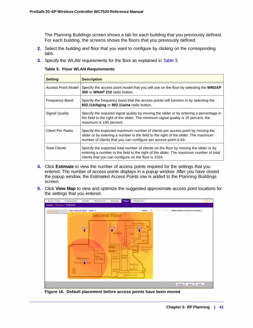
The Planning Buildings screen shows a tab for each building that you previously defined. For each building, the screens shows the floors that you previously defined.
2. Select the building and floor that you want to configure by clicking on the corresponding tabs.
3. Specify the WLAN requirements for the floor as explained in Table 5.
4. Click Estimate to view the number of access points required for the settings that you entered. The number of access points displays in a popup window. After you have closed the popup window, the Estimated Access Points row is added to the Planning Buildings screen.
5. Click View Map to view and optimize the suggested approximate access point locations for the settings that you entered.
Figure 16. Default placement before access points have been moved
Table 5. Floor WLAN Requirements
Setting Description
Access Point Model Specify the access point model that you will use on the floor by selecting the WNDAP 350 or WNAP 210 radio button.
Frequency Band Specify the frequency band that the access points will function in by selecting the 802.11b/bg/ng or 802.11a/na radio button.
Signal Quality Specify the required signal quality by moving the slider or by entering a percentage in the field to the right of the slider. The minimum signal quality is 25 percent, the maximum is 100 percent.
Client Per Radio Specify the expected maximum number of clients per access point by moving the slider or by entering a number in the field to the right of the slider. The maximum number of clients that you can configure per access point is 64.
Total Clients Specify the expected total number of clients on the floor by moving the slider or by entering a number in the field to the right of the slider. The maximum number of total clients that you can configure on the floor is 1024.
Chapter 3: RF Planning | 41
ProSafe 20-AP Wireless Controller WC7520 Reference Manual
Note that the planning tool only provides default placement and shows the coverage area for each access point.
6. Move the access points to optimize coverage in desired areas and avoid coverage in unwanted areas based on the floor plan.
Colored circles around the access point symbols indicate the expected approximate coverage of the individual access point, and the color of the circle represents the expected quality of the signal strength: a darker color indicates signal overlap with nearby access points.
Note: A red color indicates the strongest coverage area: better than -50 dBm RSSI; an orange color better than -60 dBm; a yellow color better than -70 dBm; and so on.
Moderate overlap is required for seamless roaming. No overlap will lead to disconnections and dead spots
You can click an access point icon and drag it to manually reposition it to see how the new location would affect the coverage. Click Cancel to undo any access point repositioning changes.
Use the Zoom slider to increase or decrease the size of the map.
7. Click Save to save the location map, or click Back to return to the Planning Buildings screen without savings changes to the location map.
Note: For each floor, you can save one location map only. When you modify and save the location map, the previously saved location map is overwritten.
Viewing and Managing Heat Maps for Deployed Plans
A heat map lets you view in realtime, by wireless frequency band, the signal strength and wireless coverage for a building floor. The heat map shows the actual signal strengths that each access point is detecting from neighbor access points.
Note: For the heat maps to work correctly, the access point placement on the floor plan must closely match the actual physical location of the access points.
The heat map shows the following information
• Signal strength and wireless coverage, including coverage holes.
• Known access points that are managed by the wireless controller
Chapter 3: RF Planning | 42
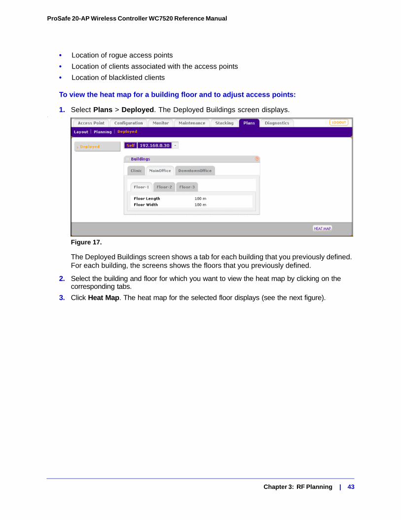
ProSafe 20-AP Wireless Controller WC7520 Reference Manual
• Location of rogue access points
• Location of clients associated with the access points
• Location of blacklisted clients
To view the heat map for a building floor and to adjust access points:
1. Select Plans > Deployed. The Deployed Buildings screen displays..
Figure 17.
The Deployed Buildings screen shows a tab for each building that you previously defined. For each building, the screens shows the floors that you previously defined.
2. Select the building and floor for which you want to view the heat map by clicking on the corresponding tabs.
3. Click Heat Map. The heat map for the selected floor displays (see the next figure).
Chapter 3: RF Planning | 43
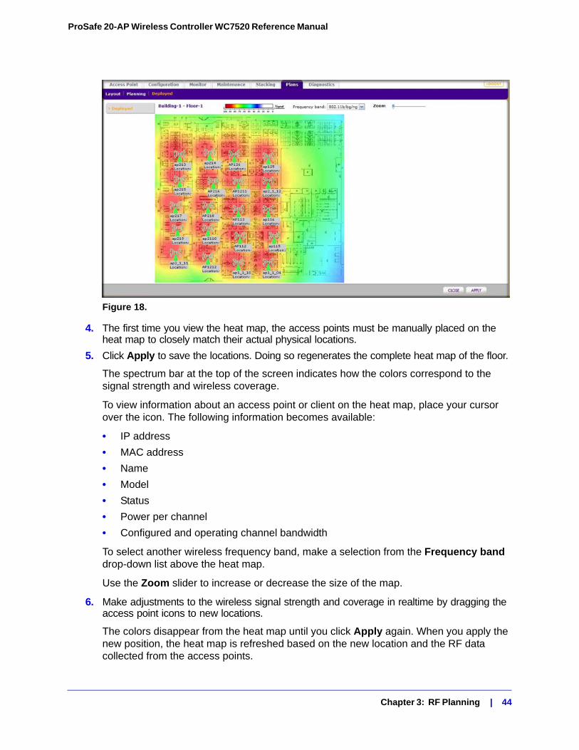
ProSafe 20-AP Wireless Controller WC7520 Reference Manual
Figure 18.
4. The first time you view the heat map, the access points must be manually placed on the heat map to closely match their actual physical locations.
5. Click Apply to save the locations. Doing so regenerates the complete heat map of the floor.
The spectrum bar at the top of the screen indicates how the colors correspond to the signal strength and wireless coverage.
To view information about an access point or client on the heat map, place your cursor over the icon. The following information becomes available:
• IP address
• MAC address
• Name
• Model
• Status
• Power per channel
• Configured and operating channel bandwidth
To select another wireless frequency band, make a selection from the Frequency band drop-down list above the heat map.
Use the Zoom slider to increase or decrease the size of the map.
6. Make adjustments to the wireless signal strength and coverage in realtime by dragging the access point icons to new locations.
The colors disappear from the heat map until you click Apply again. When you apply the new position, the heat map is refreshed based on the new location and the RF data collected from the access points.
Chapter 3: RF Planning | 44
ProSafe 20-AP Wireless Controller WC7520 Reference Manual
7. Click Apply to view how your changes affect the heat map. Depending on the size of your WLAN, it might take several minutes before the heat map is updated. If you do not want to apply the changes, click Close to return to the Deployment Building screen.
Chapter 3: RF Planning | 45
4. Access Point Discovery and Management 4
This chapter includes the following sections:• Access Point Discovery on this page
• Requirements for Auto Discovery on this page
• Using the Discovery Wizard on page 47
• Understanding the Discovery Results on page 49
• Managing the Access Point List on page 50
Access Point Discovery
You must run the Discovery Wizard for the wireless controller to discover supported NETGEAR access points on the LAN. The wireless controller can discover access points that are still in their factory default state and access points that are deployed and running. After the access points are discovered, you can add them to the Managed AP List. The wireless controller can configure, manage, and monitor the managed access points.
Requirements for Auto Discovery
If the access points still have their factory default settings, the auto discovery process should work fine. If you changed the access point configuration, make sure that the access point configuration meets the following guidelines:
• All standalone access points have SNMP and SSH enabled.
• UDP port number 7890 must be unblocked in the firewall.
• Each access point must have an IP address. All access points that are the same model ship with the same default IP address. With the exception of access points in factory default state that are in the same layer network, if more than one access point has the same IP address, then only one of them is discovered at a time. You have to add the access point to the managed list, change its IP address, and then run discovery again to discover the next access point with that IP address.
Chapter 4: Access Point Discovery and Management | 46
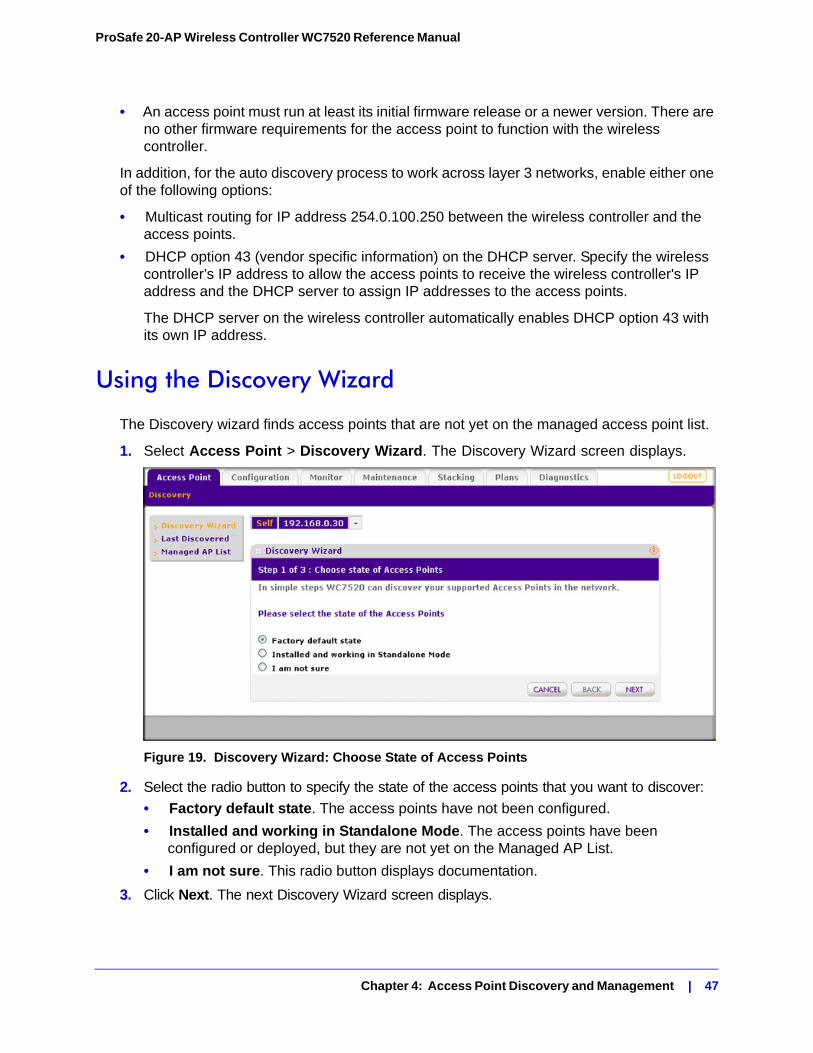
ProSafe 20-AP Wireless Controller WC7520 Reference Manual
• An access point must run at least its initial firmware release or a newer version. There are no other firmware requirements for the access point to function with the wireless controller.
In addition, for the auto discovery process to work across layer 3 networks, enable either one of the following options:
• Multicast routing for IP address 254.0.100.250 between the wireless controller and the access points.
• DHCP option 43 (vendor specific information) on the DHCP server. Specify the wireless controller’s IP address to allow the access points to receive the wireless controller's IP address and the DHCP server to assign IP addresses to the access points.
The DHCP server on the wireless controller automatically enables DHCP option 43 with its own IP address.
Using the Discovery Wizard
The Discovery wizard finds access points that are not yet on the managed access point list.
1. Select Access Point > Discovery Wizard. The Discovery Wizard screen displays.
Figure 19. Discovery Wizard: Choose State of Access Points
2. Select the radio button to specify the state of the access points that you want to discover:
• Factory default state. The access points have not been configured.
• Installed and working in Standalone Mode. The access points have been configured or deployed, but they are not yet on the Managed AP List.
• I am not sure. This radio button displays documentation.
3. Click Next. The next Discovery Wizard screen displays.
Chapter 4: Access Point Discovery and Management | 47
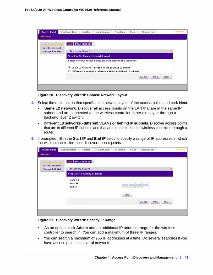
ProSafe 20-AP Wireless Controller WC7520 Reference Manual
Figure 20. Discovery Wizard: Choose Network Layout
4. Select the radio button that specifies the network layout of the access points and click Next.
• Same L2 network. Discover all access points on the LAN that are in the same IP subnet and are connected to the wireless controller either directly or through a backend layer 2 switch.
• Different L3 networks - different VLANs or behind IP subnets. Discover access points that are in different IP subnets and that are connected to the wireless controller through a router
5. If prompted, fill in the Start IP and End IP fields to specify a range of IP addresses in which the wireless controller must discover access points.
Figure 21. Discovery Wizard: Specify IP Range
• As an option, click Add to add an additional IP address range for the wireless controller to search in. You can add a maximum of three IP ranges.
• You can search a maximum of 255 IP addresses at a time. Do several searches if you have access points in several networks.
Chapter 4: Access Point Discovery and Management | 48
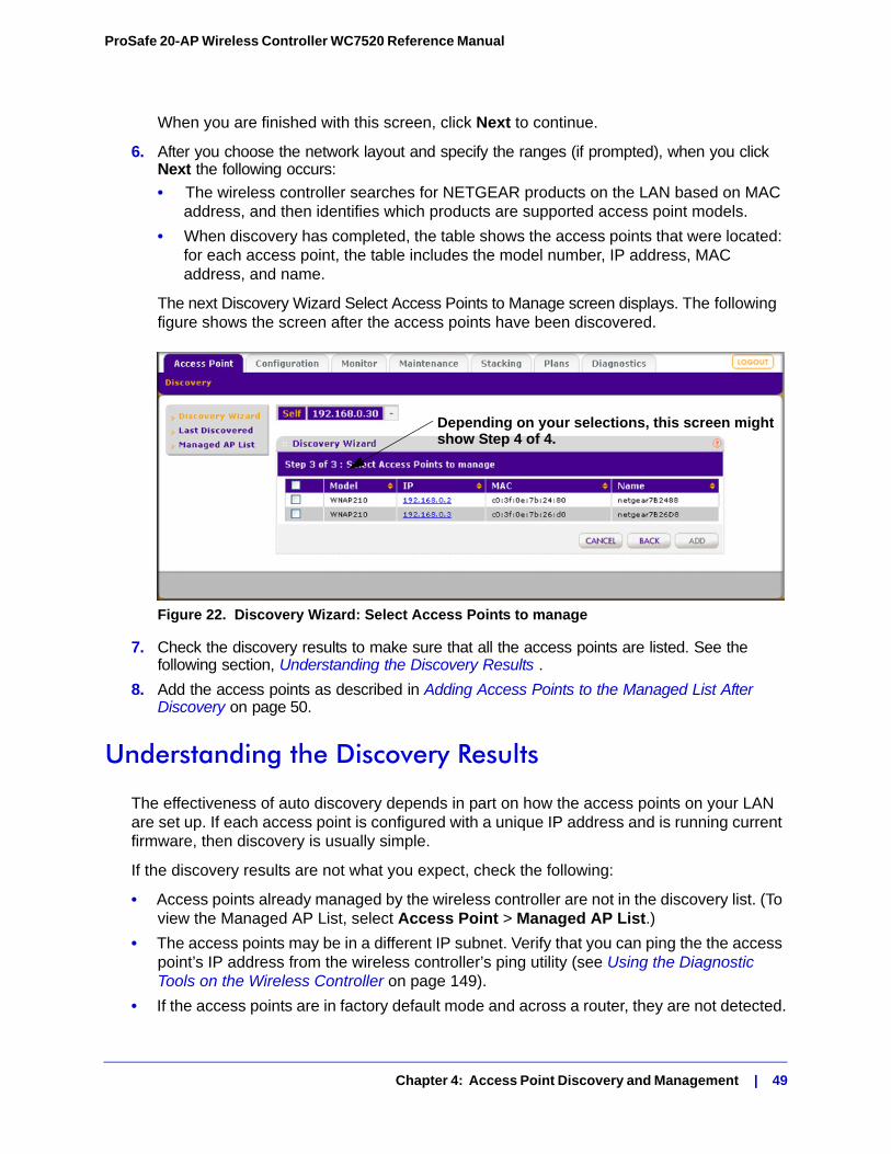
ProSafe 20-AP Wireless Controller WC7520 Reference Manual
When you are finished with this screen, click Next to continue.
6. After you choose the network layout and specify the ranges (if prompted), when you click Next the following occurs:
• The wireless controller searches for NETGEAR products on the LAN based on MAC address, and then identifies which products are supported access point models.
• When discovery has completed, the table shows the access points that were located: for each access point, the table includes the model number, IP address, MAC address, and name.
The next Discovery Wizard Select Access Points to Manage screen displays. The following figure shows the screen after the access points have been discovered.
Figure 22. Discovery Wizard: Select Access Points to manage
7. Check the discovery results to make sure that all the access points are listed. See the following section, Understanding the Discovery Results .
8. Add the access points as described in Adding Access Points to the Managed List After Discovery on page 50.
Understanding the Discovery Results
The effectiveness of auto discovery depends in part on how the access points on your LAN are set up. If each access point is configured with a unique IP address and is running current firmware, then discovery is usually simple.
If the discovery results are not what you expect, check the following:
• Access points already managed by the wireless controller are not in the discovery list. (To view the Managed AP List, select Access Point > Managed AP List.)
• The access points may be in a different IP subnet. Verify that you can ping the the access point’s IP address from the wireless controller’s ping utility (see Using the Diagnostic Tools on the Wireless Controller on page 149).
• If the access points are in factory default mode and across a router, they are not detected.
Depending on your selections, this screen mightshow Step 4 of 4.
Chapter 4: Access Point Discovery and Management | 49
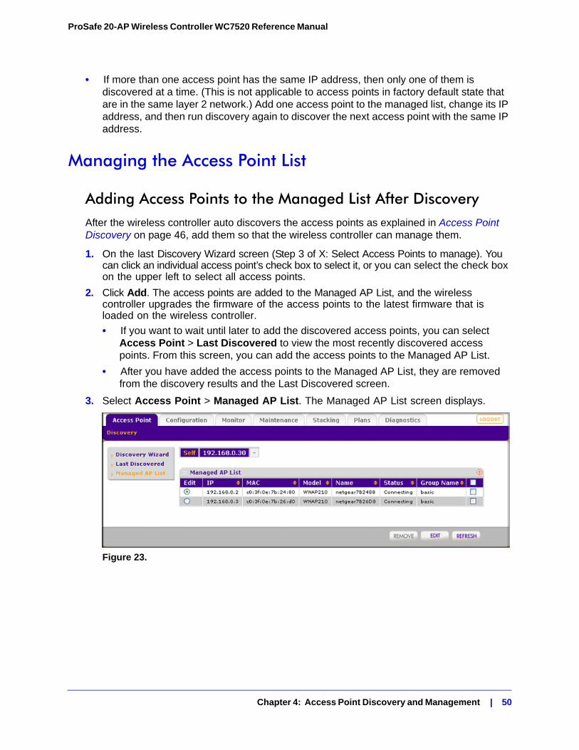
ProSafe 20-AP Wireless Controller WC7520 Reference Manual
• If more than one access point has the same IP address, then only one of them is discovered at a time. (This is not applicable to access points in factory default state that are in the same layer 2 network.) Add one access point to the managed list, change its IP address, and then run discovery again to discover the next access point with the same IP address.
Managing the Access Point List
Adding Access Points to the Managed List After DiscoveryAfter the wireless controller auto discovers the access points as explained in Access Point Discovery on page 46, add them so that the wireless controller can manage them.
1. On the last Discovery Wizard screen (Step 3 of X: Select Access Points to manage). You can click an individual access point’s check box to select it, or you can select the check box on the upper left to select all access points.
2. Click Add. The access points are added to the Managed AP List, and the wireless controller upgrades the firmware of the access points to the latest firmware that is loaded on the wireless controller.
• If you want to wait until later to add the discovered access points, you can select Access Point > Last Discovered to view the most recently discovered access points. From this screen, you can add the access points to the Managed AP List.
• After you have added the access points to the Managed AP List, they are removed from the discovery results and the Last Discovered screen.
3. Select Access Point > Managed AP List. The Managed AP List screen displays.
Figure 23.
Chapter 4: Access Point Discovery and Management | 50
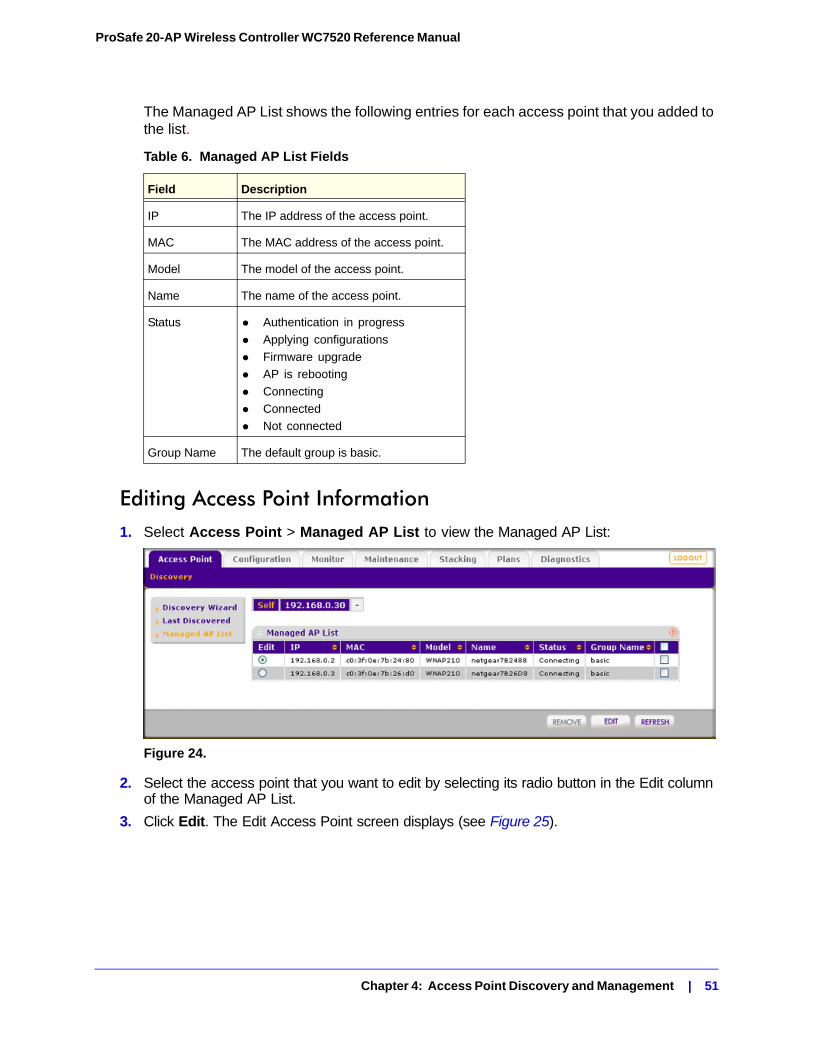
ProSafe 20-AP Wireless Controller WC7520 Reference Manual
The Managed AP List shows the following entries for each access point that you added to the list.
Editing Access Point Information1. Select Access Point > Managed AP List to view the Managed AP List:
Figure 24.
2. Select the access point that you want to edit by selecting its radio button in the Edit column of the Managed AP List.
3. Click Edit. The Edit Access Point screen displays (see Figure 25).
Table 6. Managed AP List Fields
Field Description
IP The IP address of the access point.
MAC The MAC address of the access point.
Model The model of the access point.
Name The name of the access point.
Status • Authentication in progress
• Applying configurations
• Firmware upgrade
• AP is rebooting
• Connecting
• Connected
• Not connected
Group Name The default group is basic.
Chapter 4: Access Point Discovery and Management | 51
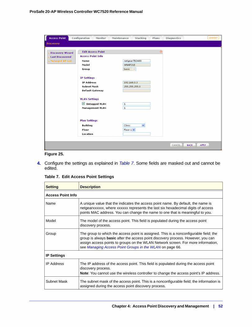
ProSafe 20-AP Wireless Controller WC7520 Reference Manual
Figure 25.
4. Configure the settings as explained in Table 7. Some fields are masked out and cannot be edited.
Table 7. Edit Access Point Settings
Setting Description
Access Point Info
Name A unique value that the indicates the access point name. By default, the name is netgearxxxxxx, where xxxxxx represents the last six hexadecimal digits of access points MAC address. You can change the name to one that is meaningful to you.
Model The model of the access point. This field is populated during the access point discovery process.
Group The group to which the access point is assigned. This is a nonconfigurable field; the group is always basic after the access point discovery process. However, you can assign access points to groups on the WLAN Network screen. For more information, see Managing Access Point Groups in the WLAN on page 66.
IP Settings
IP Address The IP address of the access point. This field is populated during the access point discovery process.Note: You cannot use the wireless controller to change the access point’s IP address.
Subnet Mask The subnet mask of the access point. This is a nonconfigurable field; the information is assigned during the access point discovery process.
Chapter 4: Access Point Discovery and Management | 52
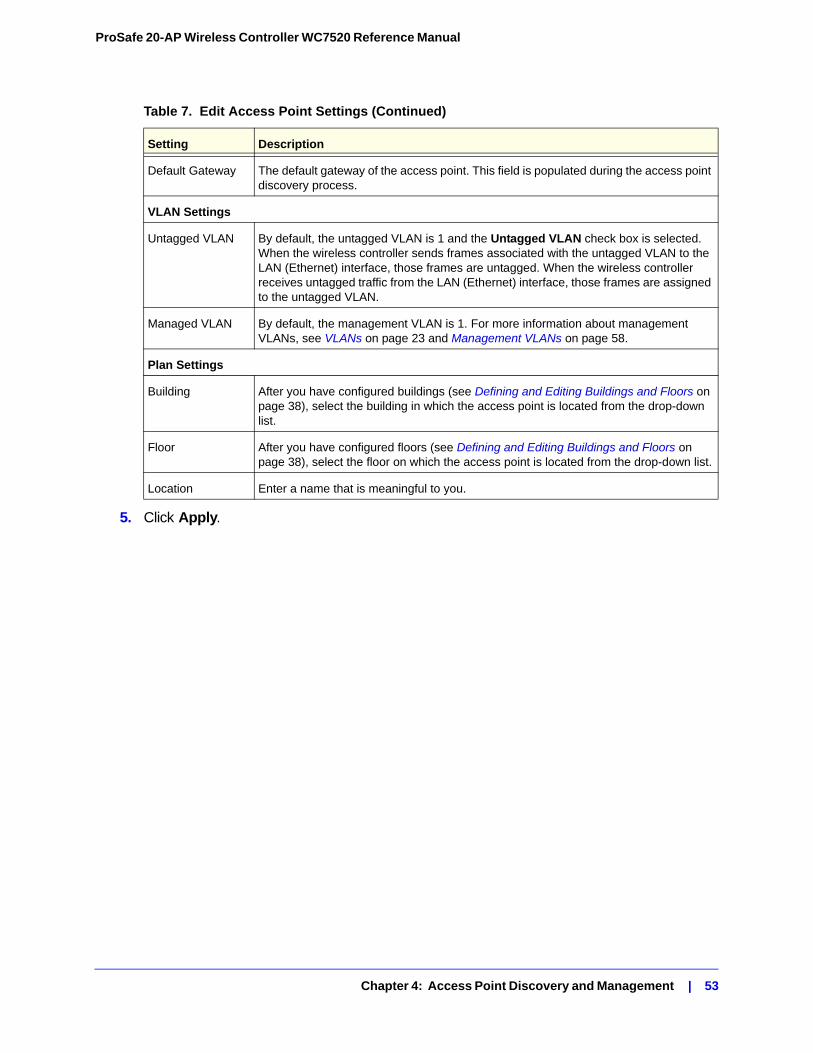
ProSafe 20-AP Wireless Controller WC7520 Reference Manual
5. Click Apply.
Default Gateway The default gateway of the access point. This field is populated during the access point discovery process.
VLAN Settings
Untagged VLAN By default, the untagged VLAN is 1 and the Untagged VLAN check box is selected. When the wireless controller sends frames associated with the untagged VLAN to the LAN (Ethernet) interface, those frames are untagged. When the wireless controller receives untagged traffic from the LAN (Ethernet) interface, those frames are assigned to the untagged VLAN.
Managed VLAN By default, the management VLAN is 1. For more information about management VLANs, see VLANs on page 23 and Management VLANs on page 58.
Plan Settings
Building After you have configured buildings (see Defining and Editing Buildings and Floors on page 38), select the building in which the access point is located from the drop-down list.
Floor After you have configured floors (see Defining and Editing Buildings and Floors on page 38), select the floor on which the access point is located from the drop-down list.
Location Enter a name that is meaningful to you.
Table 7. Edit Access Point Settings (Continued)
Setting Description
Chapter 4: Access Point Discovery and Management | 53
5. Configuring Network Settings 5
This chapter includes the following sections:• Configuring General Settings on page 54
• Time Management on page 56
• Configuring IP and VLAN Settings on page 57
• Managing the DHCP Server on page 59
• Managing Certificates on page 60
• Configuring Syslog and Alarm Notification Settings on page 61
Configuring General Settings
Note: You must select the correct country or region of operation. It might not be legal to operate the access points in a country/region not shown here. If your location is not listed, check with your local government agency or check the NETGEAR website for more information about which channels to use.
The General Settings screen lets you configure the basic settings of your wireless controller.
Chapter 5: Configuring Network Settings | 54
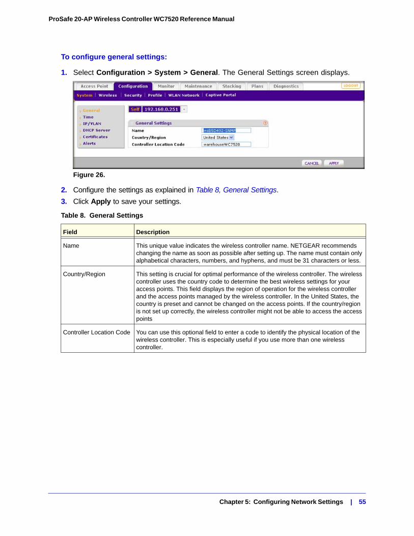
ProSafe 20-AP Wireless Controller WC7520 Reference Manual
To configure general settings:
1. Select Configuration > System > General. The General Settings screen displays.
Figure 26.
2. Configure the settings as explained in Table 8, General Settings.
3. Click Apply to save your settings.
Table 8. General Settings
Field Description
Name This unique value indicates the wireless controller name. NETGEAR recommends changing the name as soon as possible after setting up. The name must contain only alphabetical characters, numbers, and hyphens, and must be 31 characters or less.
Country/Region This setting is crucial for optimal performance of the wireless controller. The wireless controller uses the country code to determine the best wireless settings for your access points. This field displays the region of operation for the wireless controller and the access points managed by the wireless controller. In the United States, the country is preset and cannot be changed on the access points. If the country/region is not set up correctly, the wireless controller might not be able to access the access points
Controller Location Code You can use this optional field to enter a code to identify the physical location of the wireless controller. This is especially useful if you use more than one wireless controller.
Chapter 5: Configuring Network Settings | 55
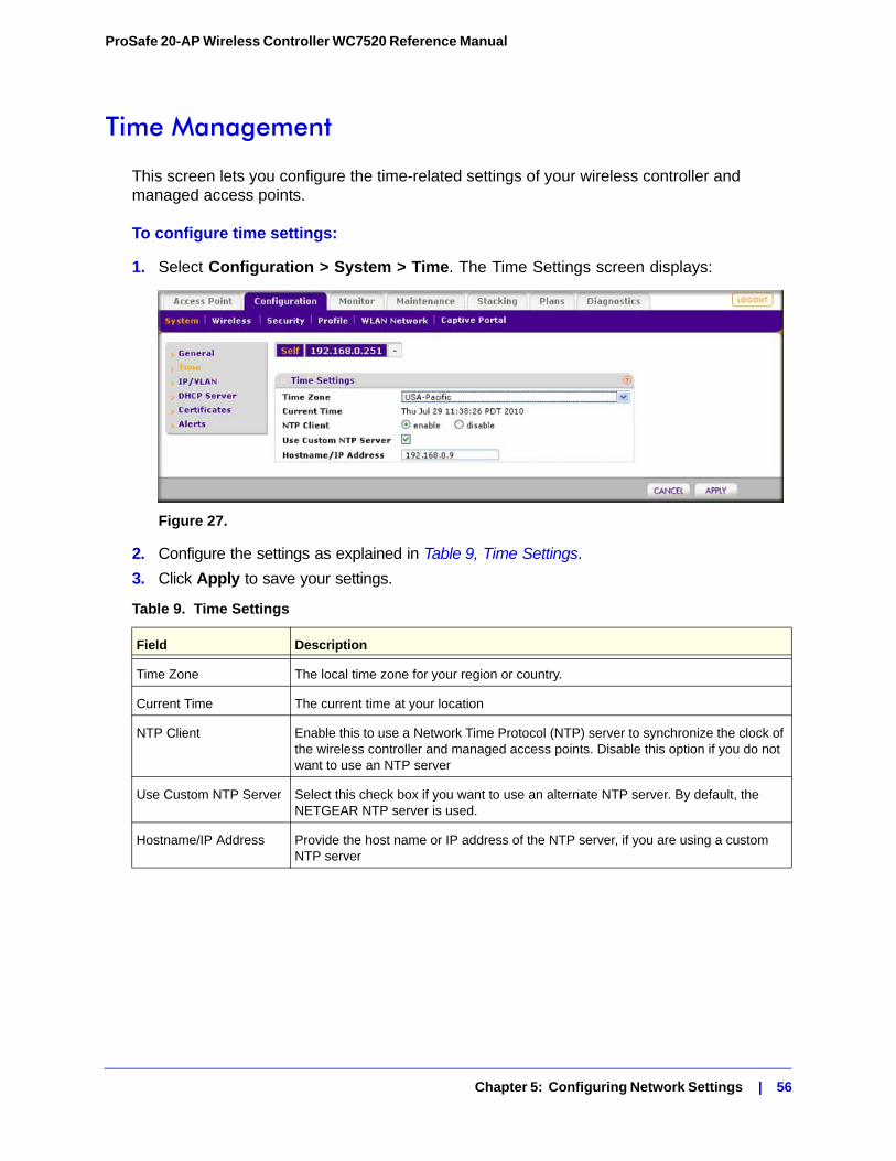
ProSafe 20-AP Wireless Controller WC7520 Reference Manual
Time Management
This screen lets you configure the time-related settings of your wireless controller and managed access points.
To configure time settings:
1. Select Configuration > System > Time. The Time Settings screen displays:
Figure 27.
2. Configure the settings as explained in Table 9, Time Settings.
3. Click Apply to save your settings.
Table 9. Time Settings
Field Description
Time Zone The local time zone for your region or country.
Current Time The current time at your location
NTP Client Enable this to use a Network Time Protocol (NTP) server to synchronize the clock of the wireless controller and managed access points. Disable this option if you do not want to use an NTP server
Use Custom NTP Server Select this check box if you want to use an alternate NTP server. By default, the NETGEAR NTP server is used.
Hostname/IP Address Provide the host name or IP address of the NTP server, if you are using a custom NTP server
Chapter 5: Configuring Network Settings | 56
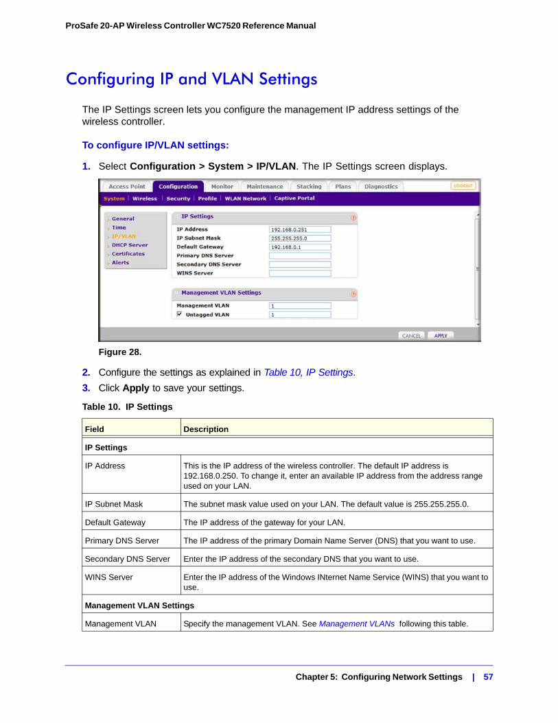
ProSafe 20-AP Wireless Controller WC7520 Reference Manual
Configuring IP and VLAN Settings
The IP Settings screen lets you configure the management IP address settings of the wireless controller.
To configure IP/VLAN settings:
1. Select Configuration > System > IP/VLAN. The IP Settings screen displays.
Figure 28.
2. Configure the settings as explained in Table 10, IP Settings.
3. Click Apply to save your settings.
Table 10. IP Settings
Field Description
IP Settings
IP Address This is the IP address of the wireless controller. The default IP address is 192.168.0.250. To change it, enter an available IP address from the address range used on your LAN.
IP Subnet Mask The subnet mask value used on your LAN. The default value is 255.255.255.0.
Default Gateway The IP address of the gateway for your LAN.
Primary DNS Server The IP address of the primary Domain Name Server (DNS) that you want to use.
Secondary DNS Server Enter the IP address of the secondary DNS that you want to use.
WINS Server Enter the IP address of the Windows INternet Name Service (WINS) that you want to use.
Management VLAN Settings
Management VLAN Specify the management VLAN. See Management VLANs following this table.
Chapter 5: Configuring Network Settings | 57
ProSafe 20-AP Wireless Controller WC7520 Reference Manual
Management VLANsManagement VLANs are used for all SNMP and HTTP traffic to and from the wireless controller and managed access points.
For large deployments, NETGEAR recommends that the wireless controller and access points are in separate VLANs to ensure uninterrupted connectivity between the wireless controller and the access points.
The wireless controller and access points share heartbeat messages to keep synchronized and share configurations and client key data to facilitate seamless roaming.
Untagged VLANsWhen the Untagged VLAN check box is selected, one VLAN can be configured as an untagged VLAN:
• When the wireless controller sends frames associated with the untagged VLAN to the LAN (Ethernet) interface, those frames do not carry an 802.1Q VLAN header.
• When the wireless controller receives untagged traffic from the LAN (Ethernet) interface, those frames are assigned to the untagged VLAN.
If t the Untagged VLAN check box is cleared, the wireless controller tags all outgoing LAN (Ethernet) frames, and accepts only incoming frames that are tagged with known VLAN IDs.
Note: The Untagged VLAN check box should be cleared only if the hubs or switches on your LAN support the VLAN (802.1Q) standard. Likewise, the untagged VLAN value should be changed only if the hubs and switches on your LAN support the VLAN (802.1Q) standard.
Changing either of these values will result in a loss of IP connectivity if the hubs and switches on your network have not yet been configured with the corresponding VLANs.
Untagged VLAN Select this check box if the configured VLAN is untagged. See Untagged VLANs following this table.
Table 10. IP Settings (Continued)
Field Description
Chapter 5: Configuring Network Settings | 58
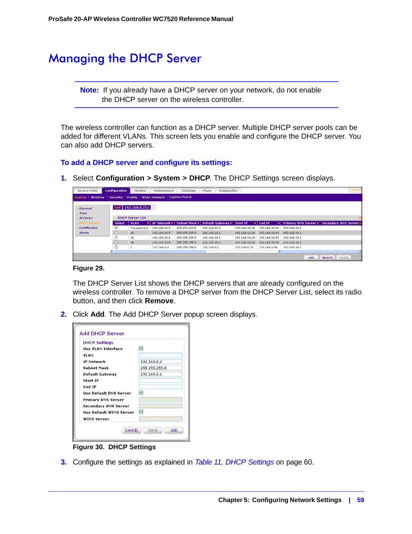
ProSafe 20-AP Wireless Controller WC7520 Reference Manual
Managing the DHCP Server
Note: If you already have a DHCP server on your network, do not enable the DHCP server on the wireless controller.
The wireless controller can function as a DHCP server. Multiple DHCP server pools can be added for different VLANs. This screen lets you enable and configure the DHCP server. You can also add DHCP servers.
To add a DHCP server and configure its settings:
1. Select Configuration > System > DHCP. The DHCP Settings screen displays.
Figure 29.
The DHCP Server List shows the DHCP servers that are already configured on the wireless controller. To remove a DHCP server from the DHCP Server List, select its radio button, and then click Remove.
2. Click Add. The Add DHCP Server popup screen displays.
Figure 30. DHCP Settings
3. Configure the settings as explained in Table 11, DHCP Settings on page 60.
Chapter 5: Configuring Network Settings | 59
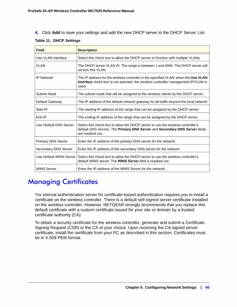
ProSafe 20-AP Wireless Controller WC7520 Reference Manual
4. Click Add to save your settings and add the new DHCP server to the DHCP Server List.
Managing Certificates
The internal authentication server for certificate-based authentication requires you to install a certificate on the wireless controller. There is a default self-signed server certificate installed on the wireless controller. However, NETGEAR strongly recommends that you replace this default certificate with a custom certificate issued for your site or domain by a trusted certificate authority (CA).
To obtain a security certificate for the wireless controller, generate and submit a Certificate Signing Request (CSR) to the CA of your choice. Upon receiving the CA-signed server certificate, install the certificate from your PC as described in this section. Certificates must be in X.509 PEM format.
Table 11. DHCP Settings
Field Description
Use VLAN Interface Select this check box to allow the DHCP server to function with multiple VLANs.
VLAN The DHCP server VLAN ID. The range is between 1 and 4094. The DHCP server will service this VLAN.
IP Network The IP address for the wireless controller in the specified VLAN; when the Use VLAN Interface check box is not selected, the wireless controller management IP/VLAN is used.
Subnet Mask The subnet mask that will be assigned to the wireless clients by the DHCP server.
Default Gateway The IP address of the default network gateway for all traffic beyond the local network.
Start IP The starting IP address of the range that can be assigned by the DHCP server.
End IP The ending IP address of the range that can be assigned by the DHCP server.
Use Default DNS Server Select this check box to allow the DHCP server to use the wireless controller’s default DNS servers. The Primary DNS Server and Secondary DNS Server fields are masked out.
Primary DNS Server Enter the IP address of the primary DNS server for the network.
Secondary DNS Server Enter the IP address of the secondary DNS server for the network.
Use Default WINS Server Select this check box to allow the DHCP server to use the wireless controller’s default WINS server. The WINS Server field is masked out.
WINS Server Enter the IP address of the WINS Server for the network.
Chapter 5: Configuring Network Settings | 60
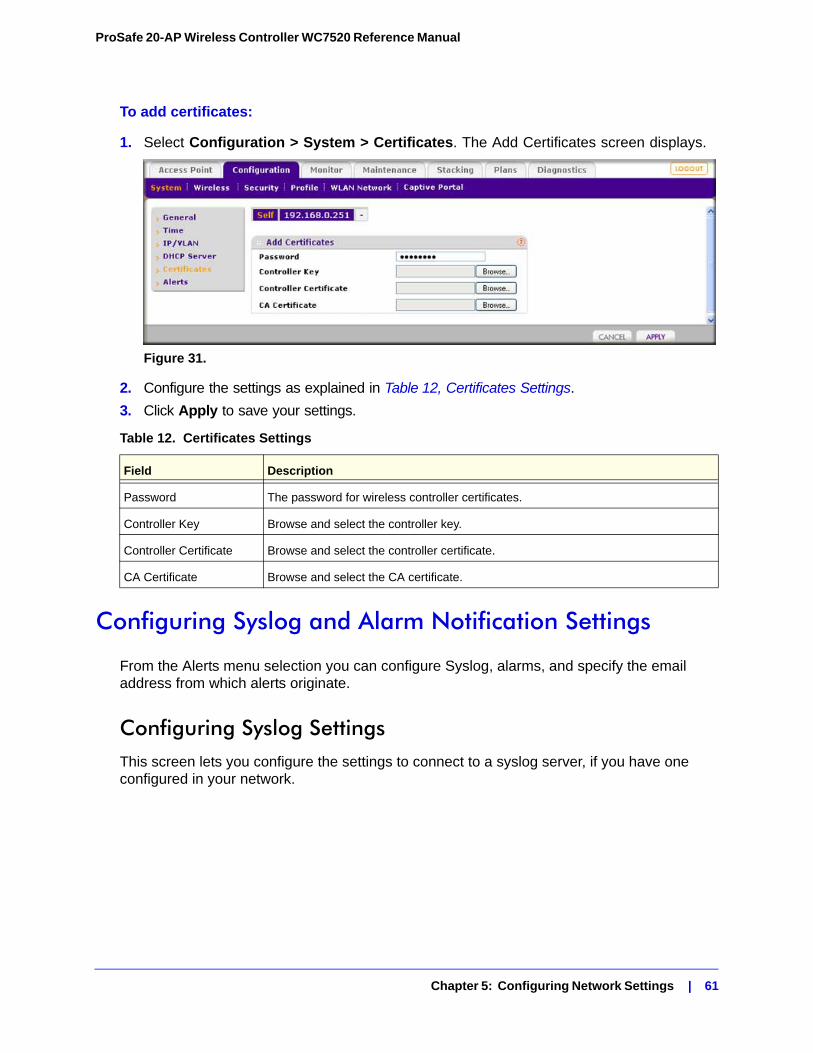
ProSafe 20-AP Wireless Controller WC7520 Reference Manual
To add certificates:
1. Select Configuration > System > Certificates. The Add Certificates screen displays.
Figure 31.
2. Configure the settings as explained in Table 12, Certificates Settings.
3. Click Apply to save your settings.
Configuring Syslog and Alarm Notification Settings
From the Alerts menu selection you can configure Syslog, alarms, and specify the email address from which alerts originate.
Configuring Syslog SettingsThis screen lets you configure the settings to connect to a syslog server, if you have one configured in your network.
Table 12. Certificates Settings
Field Description
Password The password for wireless controller certificates.
Controller Key Browse and select the controller key.
Controller Certificate Browse and select the controller certificate.
CA Certificate Browse and select the CA certificate.
Chapter 5: Configuring Network Settings | 61
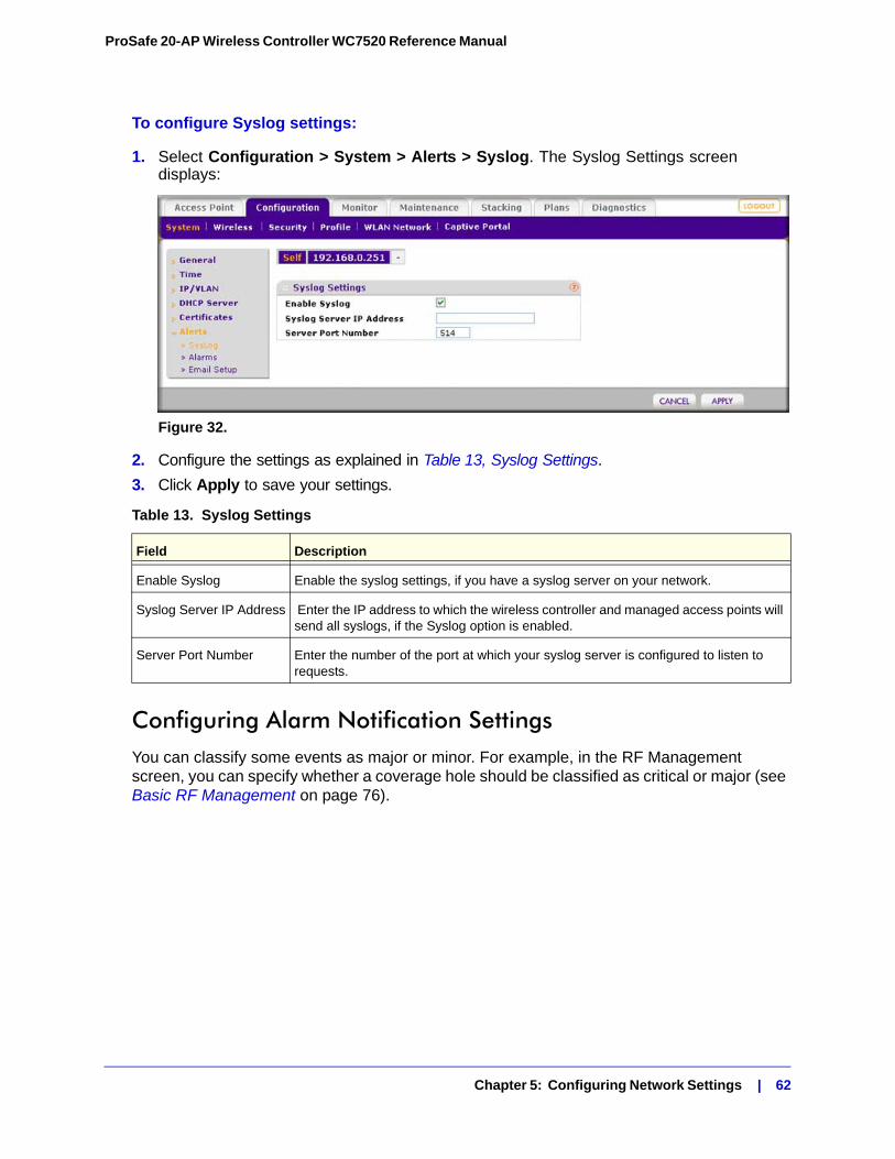
ProSafe 20-AP Wireless Controller WC7520 Reference Manual
To configure Syslog settings:
1. Select Configuration > System > Alerts > Syslog. The Syslog Settings screen displays:
Figure 32.
2. Configure the settings as explained in Table 13, Syslog Settings.
3. Click Apply to save your settings.
Configuring Alarm Notification SettingsYou can classify some events as major or minor. For example, in the RF Management screen, you can specify whether a coverage hole should be classified as critical or major (see Basic RF Management on page 76).
Table 13. Syslog Settings
Field Description
Enable Syslog Enable the syslog settings, if you have a syslog server on your network.
Syslog Server IP Address Enter the IP address to which the wireless controller and managed access points will send all syslogs, if the Syslog option is enabled.
Server Port Number Enter the number of the port at which your syslog server is configured to listen to requests.
Chapter 5: Configuring Network Settings | 62
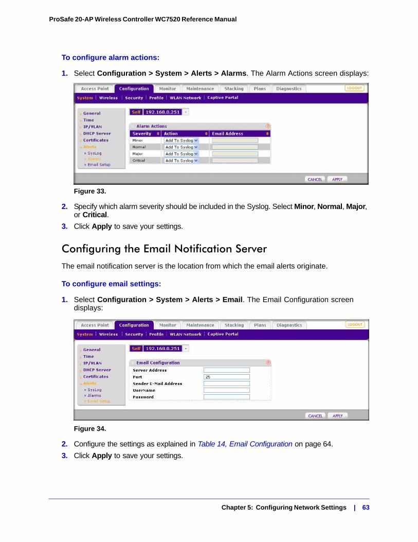
ProSafe 20-AP Wireless Controller WC7520 Reference Manual
To configure alarm actions:
1. Select Configuration > System > Alerts > Alarms. The Alarm Actions screen displays:
Figure 33.
2. Specify which alarm severity should be included in the Syslog. Select Minor, Normal, Major, or Critical.
3. Click Apply to save your settings.
Configuring the Email Notification ServerThe email notification server is the location from which the email alerts originate.
To configure email settings:
1. Select Configuration > System > Alerts > Email. The Email Configuration screen displays:
Figure 34.
2. Configure the settings as explained in Table 14, Email Configuration on page 64.
3. Click Apply to save your settings.
Chapter 5: Configuring Network Settings | 63
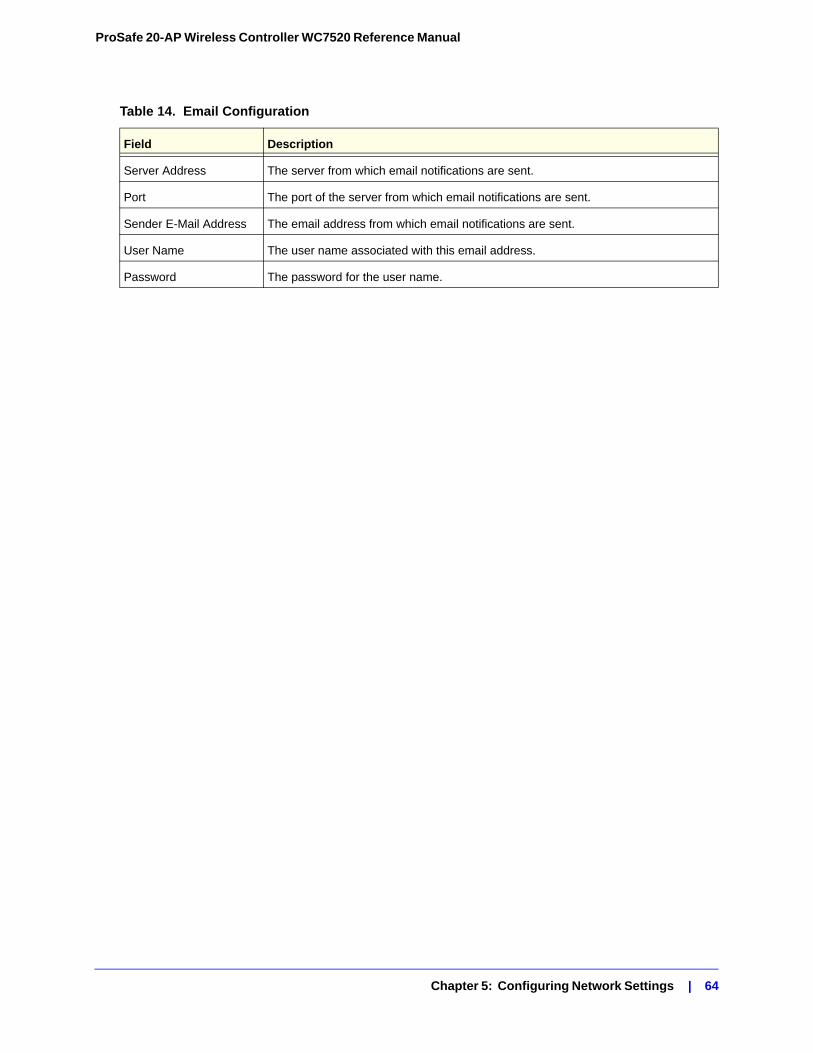
ProSafe 20-AP Wireless Controller WC7520 Reference Manual
Table 14. Email Configuration
Field Description
Server Address The server from which email notifications are sent.
Port The port of the server from which email notifications are sent.
Sender E-Mail Address The email address from which email notifications are sent.
User Name The user name associated with this email address.
Password The password for the user name.
Chapter 5: Configuring Network Settings | 64
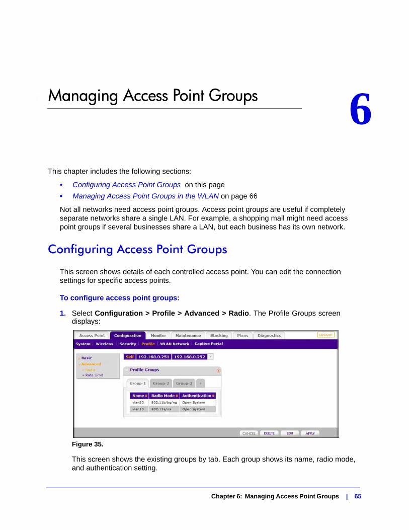
6. Managing Access Point Groups 6
This chapter includes the following sections:• Configuring Access Point Groups on this page
• Managing Access Point Groups in the WLAN on page 66
Not all networks need access point groups. Access point groups are useful if completely separate networks share a single LAN. For example, a shopping mall might need access point groups if several businesses share a LAN, but each business has its own network.
Configuring Access Point Groups
This screen shows details of each controlled access point. You can edit the connection settings for specific access points.
To configure access point groups:
1. Select Configuration > Profile > Advanced > Radio. The Profile Groups screen displays:
Figure 35.
This screen shows the existing groups by tab. Each group shows its name, radio mode, and authentication setting.
Chapter 6: Managing Access Point Groups | 65
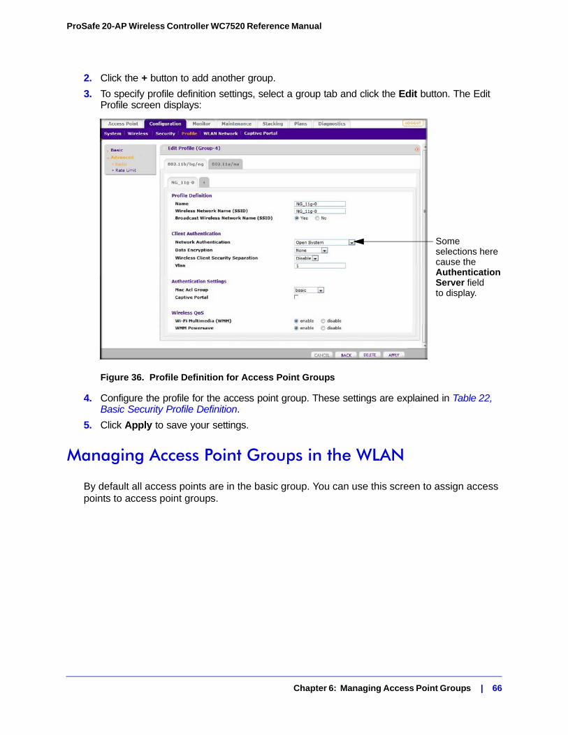
ProSafe 20-AP Wireless Controller WC7520 Reference Manual
2. Click the + button to add another group.
3. To specify profile definition settings, select a group tab and click the Edit button. The Edit Profile screen displays:
Figure 36. Profile Definition for Access Point Groups
4. Configure the profile for the access point group. These settings are explained in Table 22, Basic Security Profile Definition.
5. Click Apply to save your settings.
Managing Access Point Groups in the WLAN
By default all access points are in the basic group. You can use this screen to assign access points to access point groups.
Some selections herecause theAuthenticationServer fieldto display.
Chapter 6: Managing Access Point Groups | 66
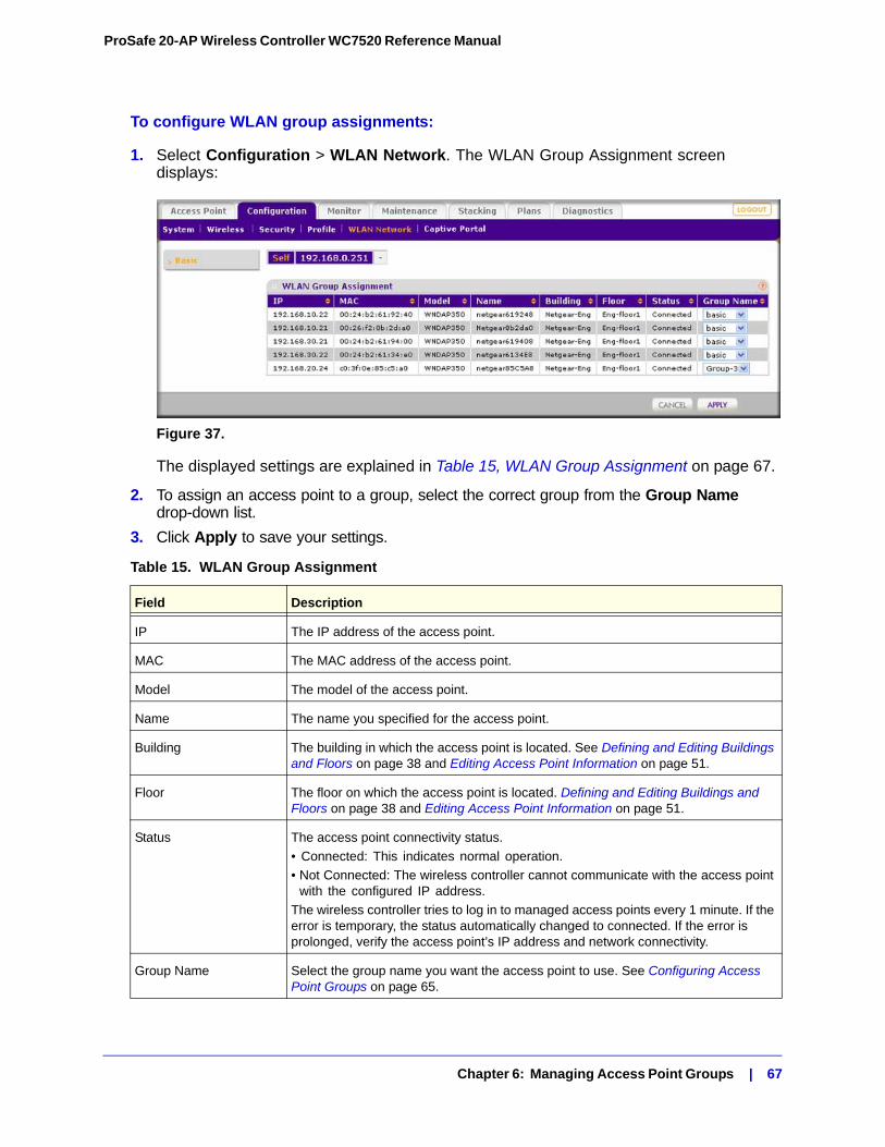
ProSafe 20-AP Wireless Controller WC7520 Reference Manual
To configure WLAN group assignments:
1. Select Configuration > WLAN Network. The WLAN Group Assignment screen displays:
Figure 37.
The displayed settings are explained in Table 15, WLAN Group Assignment on page 67.
2. To assign an access point to a group, select the correct group from the Group Name drop-down list.
3. Click Apply to save your settings.
Table 15. WLAN Group Assignment
Field Description
IP The IP address of the access point.
MAC The MAC address of the access point.
Model The model of the access point.
Name The name you specified for the access point.
Building The building in which the access point is located. See Defining and Editing Buildings and Floors on page 38 and Editing Access Point Information on page 51.
Floor The floor on which the access point is located. Defining and Editing Buildings and Floors on page 38 and Editing Access Point Information on page 51.
Status The access point connectivity status.
• Connected: This indicates normal operation.
• Not Connected: The wireless controller cannot communicate with the access point with the configured IP address.
The wireless controller tries to log in to managed access points every 1 minute. If the error is temporary, the status automatically changed to connected. If the error is prolonged, verify the access point’s IP address and network connectivity.
Group Name Select the group name you want the access point to use. See Configuring Access Point Groups on page 65.
Chapter 6: Managing Access Point Groups | 67
7. Configuring Wireless Settings 7
This chapter includes the following sections:• Configuring the Radio on this page
• Configuring Wireless Settings on page 70
• Configuring Channels on page 73
• Specifying RF Management on page 75
• Configuring QoS for Access Point Groups on page 78
• Configuring Load Balancing on page 79
• Configuring Rate Limiting on page 81
During initial set up, enter your country and region in the General Settings screen (Configuring General Settings on page 54). Based on your location and environment, the wireless controller determines the recommended wireless settings for your access points, and establishes these settings the defaults that will be sent to your managed access points. When you are ready to configure your access points, NETGEAR recommends using the default settings as they are unless you have specific reasons to change them.
CAUTION:
Before you use the wireless controller controller to configure your access points, first configure security (see Configuring Security and Wireless Security Profiles in Chapter 8). If security is not set up, or is incorrect, when the wireless controller configures the access points, you could accidentally wipe out all security, leaving your entire network open to access.
Chapter 7: Configuring Wireless Settings | 68
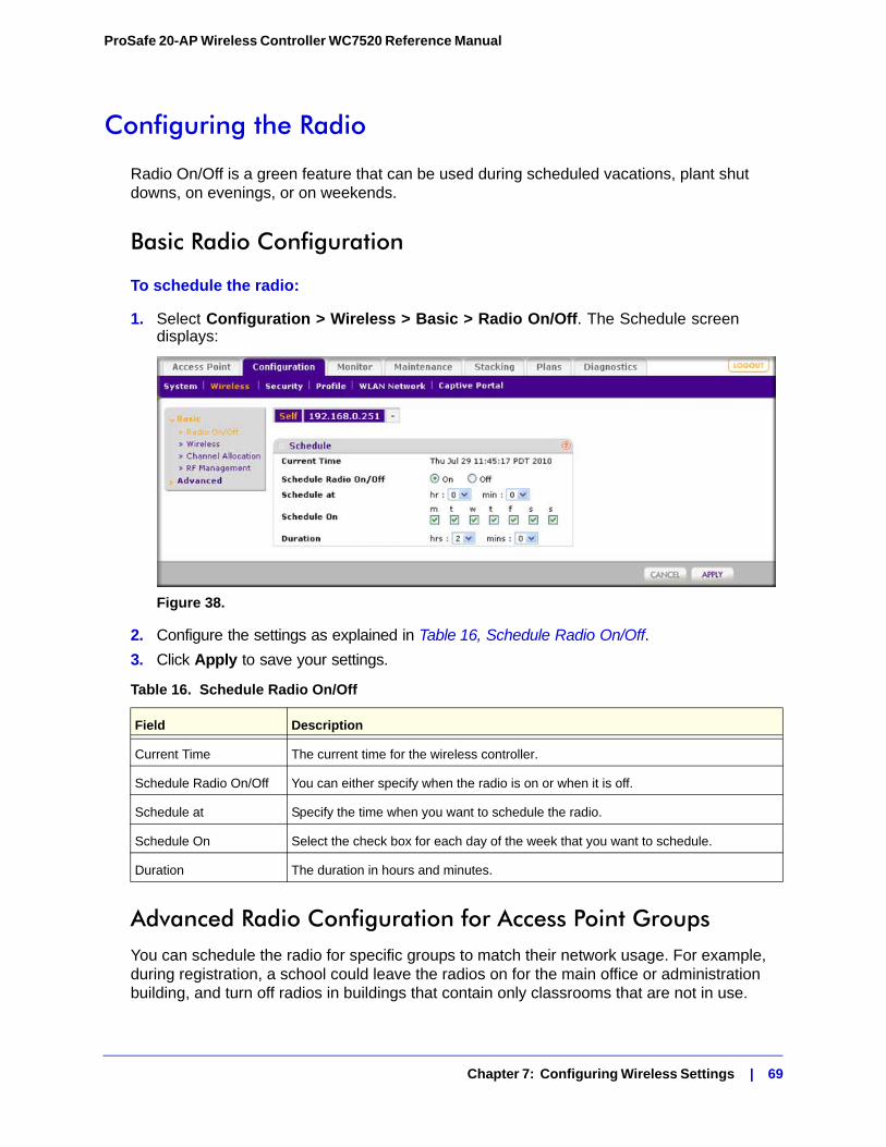
ProSafe 20-AP Wireless Controller WC7520 Reference Manual
Configuring the Radio
Radio On/Off is a green feature that can be used during scheduled vacations, plant shut downs, on evenings, or on weekends.
Basic Radio Configuration
To schedule the radio:
1. Select Configuration > Wireless > Basic > Radio On/Off. The Schedule screen displays:
Figure 38.
2. Configure the settings as explained in Table 16, Schedule Radio On/Off.
3. Click Apply to save your settings.
Advanced Radio Configuration for Access Point GroupsYou can schedule the radio for specific groups to match their network usage. For example, during registration, a school could leave the radios on for the main office or administration building, and turn off radios in buildings that contain only classrooms that are not in use.
Table 16. Schedule Radio On/Off
Field Description
Current Time The current time for the wireless controller.
Schedule Radio On/Off You can either specify when the radio is on or when it is off.
Schedule at Specify the time when you want to schedule the radio.
Schedule On Select the check box for each day of the week that you want to schedule.
Duration The duration in hours and minutes.
Chapter 7: Configuring Wireless Settings | 69
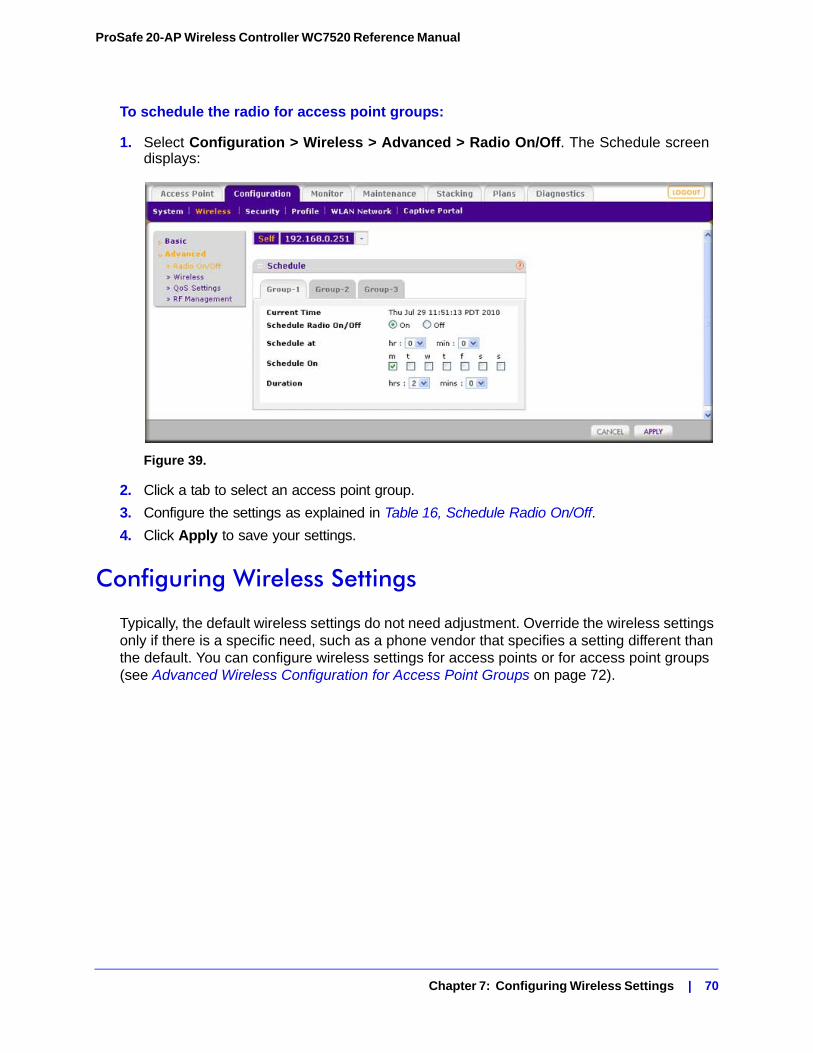
ProSafe 20-AP Wireless Controller WC7520 Reference Manual
To schedule the radio for access point groups:
1. Select Configuration > Wireless > Advanced > Radio On/Off. The Schedule screen displays:
Figure 39.
2. Click a tab to select an access point group.
3. Configure the settings as explained in Table 16, Schedule Radio On/Off.
4. Click Apply to save your settings.
Configuring Wireless Settings
Typically, the default wireless settings do not need adjustment. Override the wireless settings only if there is a specific need, such as a phone vendor that specifies a setting different than the default. You can configure wireless settings for access points or for access point groups (see Advanced Wireless Configuration for Access Point Groups on page 72).
Chapter 7: Configuring Wireless Settings | 70
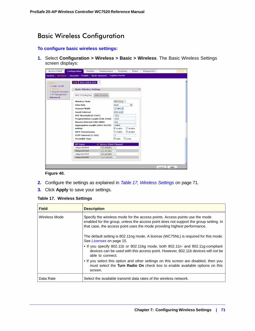
ProSafe 20-AP Wireless Controller WC7520 Reference Manual
Basic Wireless Configuration
To configure basic wireless settings:
1. Select Configuration > Wireless > Basic > Wireless. The Basic Wireless Settings screen displays:
Figure 40.
2. Configure the settings as explained in Table 17, Wireless Settings on page 71.
3. Click Apply to save your settings.
Table 17. Wireless Settings
Field Description
Wireless Mode Specify the wireless mode for the access points. Access points use the mode enabled for the group, unless the access point does not support the group setting. In that case, the access point uses the mode providing highest performance.
The default setting is 802.11ng mode. A license (WC75NL) is required for this mode. See Licenses on page 15.
• If you specify 802.11b or 802.11bg mode, both 802.11n- and 802.11g-compliant devices can be used with this access point. However, 802.11b devices will not be able to connect.
• If you select this option and other settings on this screen are disabled, then you must select the Turn Radio On check box to enable available options on this screen.
Data Rate Select the available transmit data rates of the wireless network.
Chapter 7: Configuring Wireless Settings | 71
ProSafe 20-AP Wireless Controller WC7520 Reference Manual
Advanced Wireless Configuration for Access Point GroupsNETGEAR recommends using the default settings as they are to configure your access points unless you have specific reasons to change them. You can configure wireless settings for access points (see Configuring Wireless Settings on page 70) or for access point groups.
Channel Width (11n only) Select the available channel width of the access point. A wider channel improves the performance, but some legacy devices can operate only on either 20 MHz or 40 MHz.
Guard Interval (11n only) Select the value that will protect transmissions from interference. A shorter guard interval improves performance, but some legacy devices can operate only with a long guard interval.
RTS Threshold (0-2347) The transmission mechanism (CSMA/CA or CSMA/CD) for the packets. If the packet size is equal to or less than this threshold, then the data frame is transmitted immediately. However, if the packet size is larger than the specified value, then the transmitting station must send out an Request to Send Threshold (RTS) packet to the receiving station, and then must wait for the receiving station to send back a Clear to Send (CTS) packet before sending the actual packet data.
Fragmentation Length (256-2346)
The maximum packet size that used for fragmentation of data packets. Packets larger than the specified fragmentation length are broken up into smaller packets before being transmitted. The fragmentation length must be an even number.
Beacon Interval (100-1000)
The time interval for each beacon transmission that allows the access point to synchronize the wireless network.
Aggregation Length (1024-65535, 11n only)
The length that defines the maximum length of Aggregated MAC Protocol Data Unit (AMPDU) packets. Larger aggregation lengths might sometimes lead to better network performance. Aggregation is a mechanism used to achieve higher throughput.
AMPDU (11n only) Allow the aggregation of several MAC frames into a single large frame to achieve higher throughput. Enabling AMPDU can sometimes lead to better network performance.
RIFS Transmission (11n only)
Enable the Reduced Interframe Space (RIFS) option to allow transmission of successive frames at different transmit powers. Enabling RIFS can lead to better network performance.
DTIM Interval (1–255) Enter the DTIM or the data beacon rate that you want to use. This sets the message period of the beacon delivery traffic indication in multiples of beacon intervals.
Preamble Type (11b/bg only)
A long transmit preamble can provide a more reliable connection or a slightly longer range. A short transmit preamble gives better performance. The Auto setting automatically handles both long and short preambles. The default is Auto.
Table 17. Wireless Settings (Continued)
Field Description
Chapter 7: Configuring Wireless Settings | 72
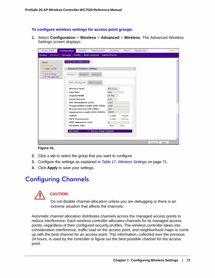
ProSafe 20-AP Wireless Controller WC7520 Reference Manual
To configure wireless settings for access point groups:
1. Select Configuration > Wireless > Advanced > Wireless. The Advanced Wireless Settings screen displays:
Figure 41.
2. Click a tab to select the group that you want to configure.
3. Configure the settings as explained in Table 17, Wireless Settings on page 71.
4. Click Apply to save your settings.
Configuring Channels
CAUTION:
Do not disable channel allocation unless you are debugging or there is an extreme situation that affects the channels.
Automatic channel allocation distributes channels across the managed access points to reduce interference. Each wireless controller allocates channels for its managed access points, regardless of their configured security profiles. The wireless controller takes into consideration interference, traffic load on the access point, and neighborhood maps to come up with the best channel for an access point. This information, collected over the previous 24 hours, is used by the controller to figure out the best possible channel for the access point.
Chapter 7: Configuring Wireless Settings | 73
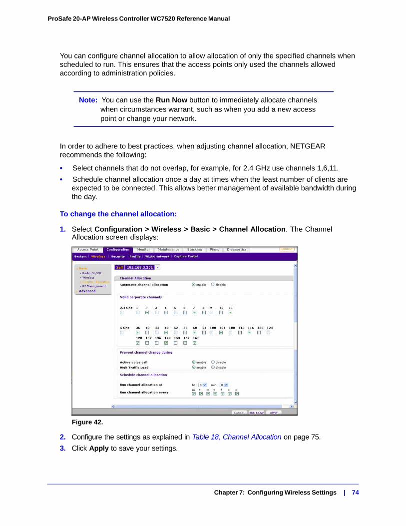
ProSafe 20-AP Wireless Controller WC7520 Reference Manual
You can configure channel allocation to allow allocation of only the specified channels when scheduled to run. This ensures that the access points only used the channels allowed according to administration policies.
Note: You can use the Run Now button to immediately allocate channels when circumstances warrant, such as when you add a new access point or change your network.
In order to adhere to best practices, when adjusting channel allocation, NETGEAR recommends the following:
• Select channels that do not overlap, for example, for 2.4 GHz use channels 1,6,11.
• Schedule channel allocation once a day at times when the least number of clients are expected to be connected. This allows better management of available bandwidth during the day.
To change the channel allocation:
1. Select Configuration > Wireless > Basic > Channel Allocation. The Channel Allocation screen displays:
Figure 42.
2. Configure the settings as explained in Table 18, Channel Allocation on page 75.
3. Click Apply to save your settings.
Chapter 7: Configuring Wireless Settings | 74
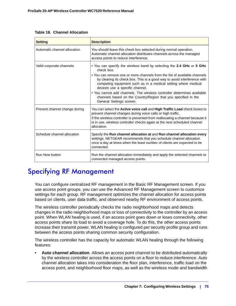
ProSafe 20-AP Wireless Controller WC7520 Reference Manual
Specifying RF Management
You can configure centralized RF management in the Basic RF Management screen. If you use access point groups, you can use the Advanced RF Management screen to customize settings for each group. RF management optimizes the channel allocation for access points based on clients, user data traffic, and observed nearby RF environment of access points.
The wireless controller periodically checks the radio neighborhood maps and detects changes in the radio neighborhood maps or loss of connectivity to the controller by an access point. When WLAN healing is used, if an access point goes down or loses connectivity, other access points share its load to avoid a coverage hole. To do this, the other access points increase their transmit power. WLAN healing is configured per security profile group and runs between the access points sharing common security configuration.
The wireless controller has the capacity for automatic WLAN healing through the following features:
• Auto channel allocation. Allows an access point channel to be distributed automatically by the wireless controller across the access points on a floor to reduce interference. Auto channel allocation takes into consideration the floor plan, interference, traffic load on the access point, and neighborhood floor maps, as well as the wireless mode and bandwidth
Table 18. Channel Allocation
Setting Description
Automatic channel allocation You should leave this check box selected during normal operation. Automatic channel allocation distributes channels across the managed access points to reduce interference.
Valid corporate channels • You can specify the wireless band by selecting the 2.4 GHz or 5 GHz check box.
• You can remove one or more channels from the list of available channels by clearing its check box. This is a good way to avoid interference with competing equipment such as in a medical setting where medical devices use a specific channel.
• You cannot add channels. The wireless controller determines available channels based on the Country/Region that you specified in the General Settings screen.
Prevent channel change during You can select the Active voice call and High Traffic Load check boxes to prevent channel changes during voice calls or high traffic.If the wireless controller is prevented from reallocating a channel because it is in use, wireless controller checks again at the next scheduled channel allocation.
Schedule channel allocation Specify the Run channel allocation at and Run channel allocation every settings. NETGEAR recommends that you schedule channel allocation once a day at times when the least number of clients are expected to be connected.
Run Now button Run the channel allocation immediately and apply the selected channels to connected managed access points.
Chapter 7: Configuring Wireless Settings | 75
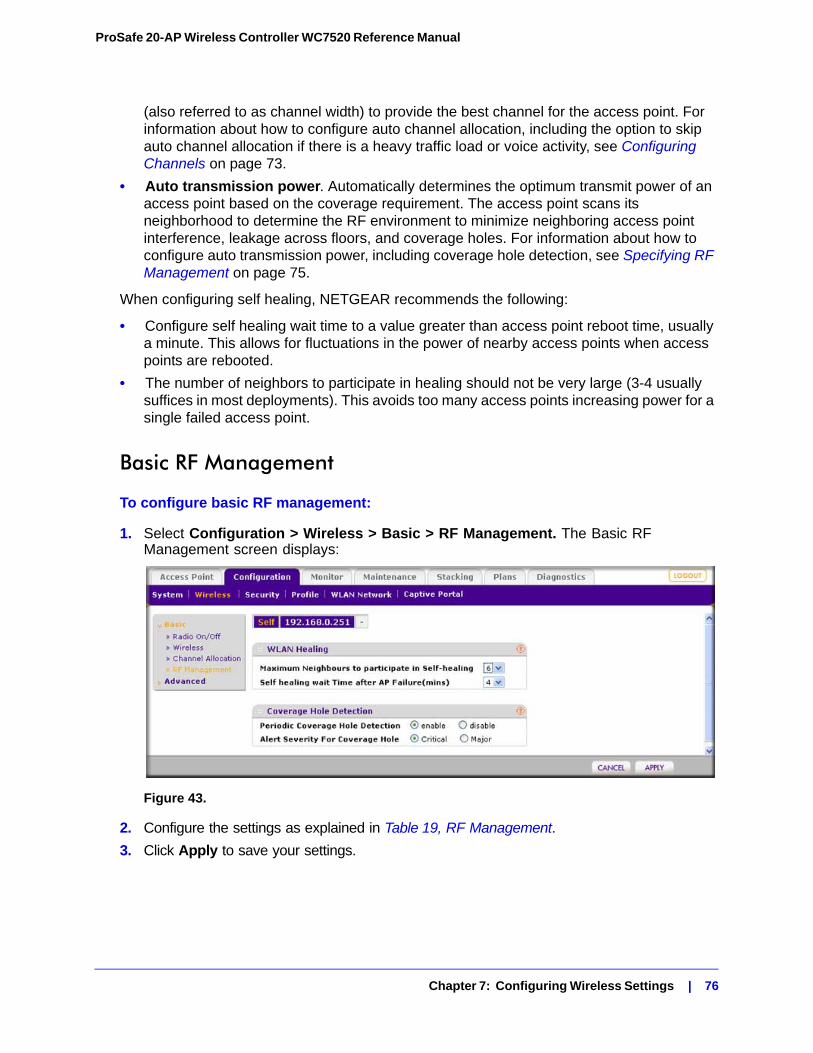
ProSafe 20-AP Wireless Controller WC7520 Reference Manual
(also referred to as channel width) to provide the best channel for the access point. For information about how to configure auto channel allocation, including the option to skip auto channel allocation if there is a heavy traffic load or voice activity, see Configuring Channels on page 73.
• Auto transmission power. Automatically determines the optimum transmit power of an access point based on the coverage requirement. The access point scans its neighborhood to determine the RF environment to minimize neighboring access point interference, leakage across floors, and coverage holes. For information about how to configure auto transmission power, including coverage hole detection, see Specifying RF Management on page 75.
When configuring self healing, NETGEAR recommends the following:
• Configure self healing wait time to a value greater than access point reboot time, usually a minute. This allows for fluctuations in the power of nearby access points when access points are rebooted.
• The number of neighbors to participate in healing should not be very large (3-4 usually suffices in most deployments). This avoids too many access points increasing power for a single failed access point.
Basic RF Management
To configure basic RF management:
1. Select Configuration > Wireless > Basic > RF Management. The Basic RF Management screen displays:
Figure 43.
2. Configure the settings as explained in Table 19, RF Management.
3. Click Apply to save your settings.
Chapter 7: Configuring Wireless Settings | 76
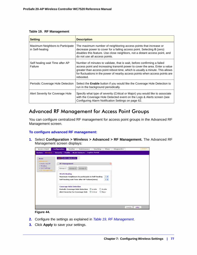
ProSafe 20-AP Wireless Controller WC7520 Reference Manual
Advanced RF Management for Access Point GroupsYou can configure centralized RF management for access point groups in the Advanced RF Management screen.
To configure advanced RF management:
1. Select Configuration > Wireless > Advanced > RF Management. The Advanced RF Management screen displays:
Figure 44.
2. Configure the settings as explained in Table 19, RF Management.
3. Click Apply to save your settings.
Table 19. RF Management
Setting Description
Maximum Neighbors to Participate in Self-healing
The maximum number of neighboring access points that increase or decrease power to cover for a failing access point. Selecting 0 (zero) disables this feature. Use close neighbors, not a distant access point, and do not use all access points.
Self healing wait Time after AP Failure
Number of minutes to validate, that is wait, before confirming a failed access point and increasing transmit power to cover the area. Enter a value greater than access point reboot time, which is usually a minute. This allows for fluctuations in the power of nearby access points when access points are rebooted.
Periodic Coverage Hole Detection Select the Enable button if you would like the Coverage Hole Detection to run in the background periodically.
Alert Severity for Coverage Hole Specify what type of severity (Critical or Major) you would like to associate with the Coverage Hole Detected event on the Logs & Alerts screen (see Configuring Alarm Notification Settings on page 62.
Chapter 7: Configuring Wireless Settings | 77
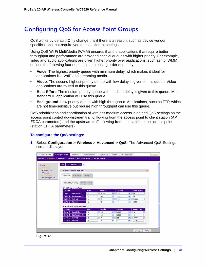
ProSafe 20-AP Wireless Controller WC7520 Reference Manual
Configuring QoS for Access Point Groups
QoS works by default. Only change this if there is a reason, such as device vendor specifications that require you to use different settings.
Using QoS Wi-Fi MultiMedia (WMM) ensures that the applications that require better throughput and performance are provided special queues with higher priority. For example, video and audio applications are given higher priority over applications, such as ftp. WMM defines the following four queues in decreasing order of priority:
• Voice: The highest priority queue with minimum delay, which makes it ideal for applications like VoIP and streaming media.
• Video: The second highest priority queue with low delay is given to this queue. Video applications are routed to this queue.
• Best Effort: The medium priority queue with medium delay is given to this queue. Most standard IP application will use this queue.
• Background: Low priority queue with high throughput. Applications, such as FTP, which are not time-sensitive but require high throughput can use this queue.
QoS prioritization and coordination of wireless medium access is on and QoS settings on the access point control downstream traffic, flowing from the access point to client station (AP EDCA parameters) and the upstream traffic flowing from the station to the access point (station EDCA parameters).
To configure the QoS settings:
1. Select Configuration > Wireless > Advanced > QoS. The Advanced QoS Settings screen displays:
Figure 45.
Chapter 7: Configuring Wireless Settings | 78
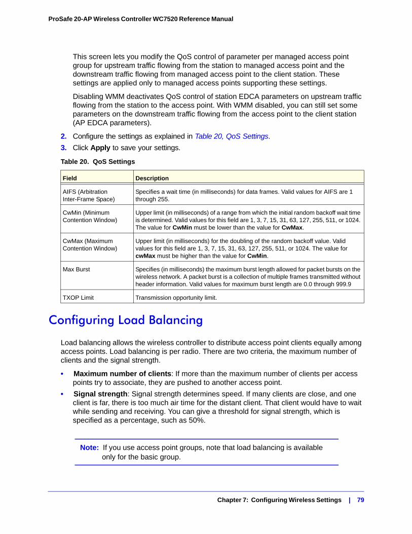
ProSafe 20-AP Wireless Controller WC7520 Reference Manual
This screen lets you modify the QoS control of parameter per managed access point group for upstream traffic flowing from the station to managed access point and the downstream traffic flowing from managed access point to the client station. These settings are applied only to managed access points supporting these settings.
Disabling WMM deactivates QoS control of station EDCA parameters on upstream traffic flowing from the station to the access point. With WMM disabled, you can still set some parameters on the downstream traffic flowing from the access point to the client station (AP EDCA parameters).
2. Configure the settings as explained in Table 20, QoS Settings.
3. Click Apply to save your settings.
Configuring Load Balancing
Load balancing allows the wireless controller to distribute access point clients equally among access points. Load balancing is per radio. There are two criteria, the maximum number of clients and the signal strength.
• Maximum number of clients: If more than the maximum number of clients per access points try to associate, they are pushed to another access point.
• Signal strength: Signal strength determines speed. If many clients are close, and one client is far, there is too much air time for the distant client. That client would have to wait while sending and receiving. You can give a threshold for signal strength, which is specified as a percentage, such as 50%.
Note: If you use access point groups, note that load balancing is available only for the basic group.
Table 20. QoS Settings
Field Description
AIFS (Arbitration Inter-Frame Space)
Specifies a wait time (in milliseconds) for data frames. Valid values for AIFS are 1 through 255.
CwMin (Minimum Contention Window)
Upper limit (in milliseconds) of a range from which the initial random backoff wait time is determined. Valid values for this field are 1, 3, 7, 15, 31, 63, 127, 255, 511, or 1024. The value for CwMin must be lower than the value for CwMax.
CwMax (Maximum Contention Window)
Upper limit (in milliseconds) for the doubling of the random backoff value. Valid values for this field are 1, 3, 7, 15, 31, 63, 127, 255, 511, or 1024. The value for cwMax must be higher than the value for CwMin.
Max Burst Specifies (in milliseconds) the maximum burst length allowed for packet bursts on the wireless network. A packet burst is a collection of multiple frames transmitted without header information. Valid values for maximum burst length are 0.0 through 999.9
TXOP Limit Transmission opportunity limit.
Chapter 7: Configuring Wireless Settings | 79
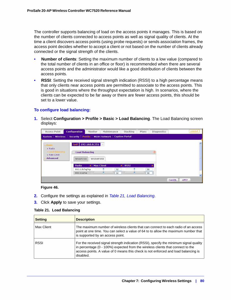
ProSafe 20-AP Wireless Controller WC7520 Reference Manual
The controller supports balancing of load on the access points it manages. This is based on the number of clients connected to access points as well as signal quality of clients. At the time a client discovers access points (using probe requests) or sends association frames, the access point decides whether to accept a client or not based on the number of clients already connected or the signal strength of the clients.
• Number of clients: Setting the maximum number of clients to a low value (compared to the total number of clients in an office or floor) is recommended when there are several access points and the administrator would like a good distribution of clients between the access points.
• RSSI: Setting the received signal strength indication (RSSI) to a high percentage means that only clients near access points are permitted to associate to the access points. This is good in situations where the throughput expectation is high. In scenarios, where the clients can be expected to be far away or there are fewer access points, this should be set to a lower value.
To configure load balancing:
1. Select Configuration > Profile > Basic > Load Balancing. The Load Balancing screen displays:
Figure 46.
2. Configure the settings as explained in Table 21, Load Balancing.
3. Click Apply to save your settings.
Table 21. Load Balancing
Setting Description
Max Client The maximum number of wireless clients that can connect to each radio of an access point at one time. You can select a value of 64 to to allow the maximum number that is supported by an access point.
RSSI For the received signal strength indication (RSSI), specify the minimum signal quality in percentage (0 - 100%) expected from the wireless clients that connect to the access points. A value of 0 means this check is not enforced and load balancing is disabled.
Chapter 7: Configuring Wireless Settings | 80
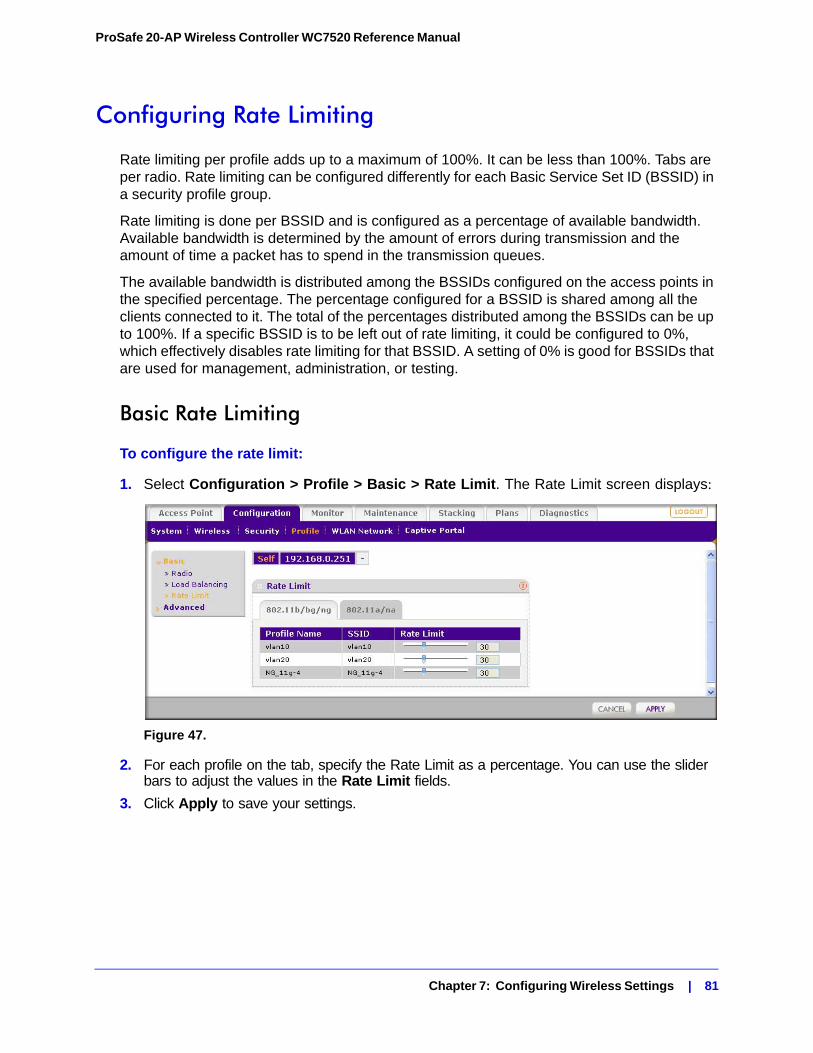
ProSafe 20-AP Wireless Controller WC7520 Reference Manual
Configuring Rate Limiting
Rate limiting per profile adds up to a maximum of 100%. It can be less than 100%. Tabs are per radio. Rate limiting can be configured differently for each Basic Service Set ID (BSSID) in a security profile group.
Rate limiting is done per BSSID and is configured as a percentage of available bandwidth. Available bandwidth is determined by the amount of errors during transmission and the amount of time a packet has to spend in the transmission queues.
The available bandwidth is distributed among the BSSIDs configured on the access points in the specified percentage. The percentage configured for a BSSID is shared among all the clients connected to it. The total of the percentages distributed among the BSSIDs can be up to 100%. If a specific BSSID is to be left out of rate limiting, it could be configured to 0%, which effectively disables rate limiting for that BSSID. A setting of 0% is good for BSSIDs that are used for management, administration, or testing.
Basic Rate Limiting
To configure the rate limit:
1. Select Configuration > Profile > Basic > Rate Limit. The Rate Limit screen displays:
Figure 47.
2. For each profile on the tab, specify the Rate Limit as a percentage. You can use the slider bars to adjust the values in the Rate Limit fields.
3. Click Apply to save your settings.
Chapter 7: Configuring Wireless Settings | 81
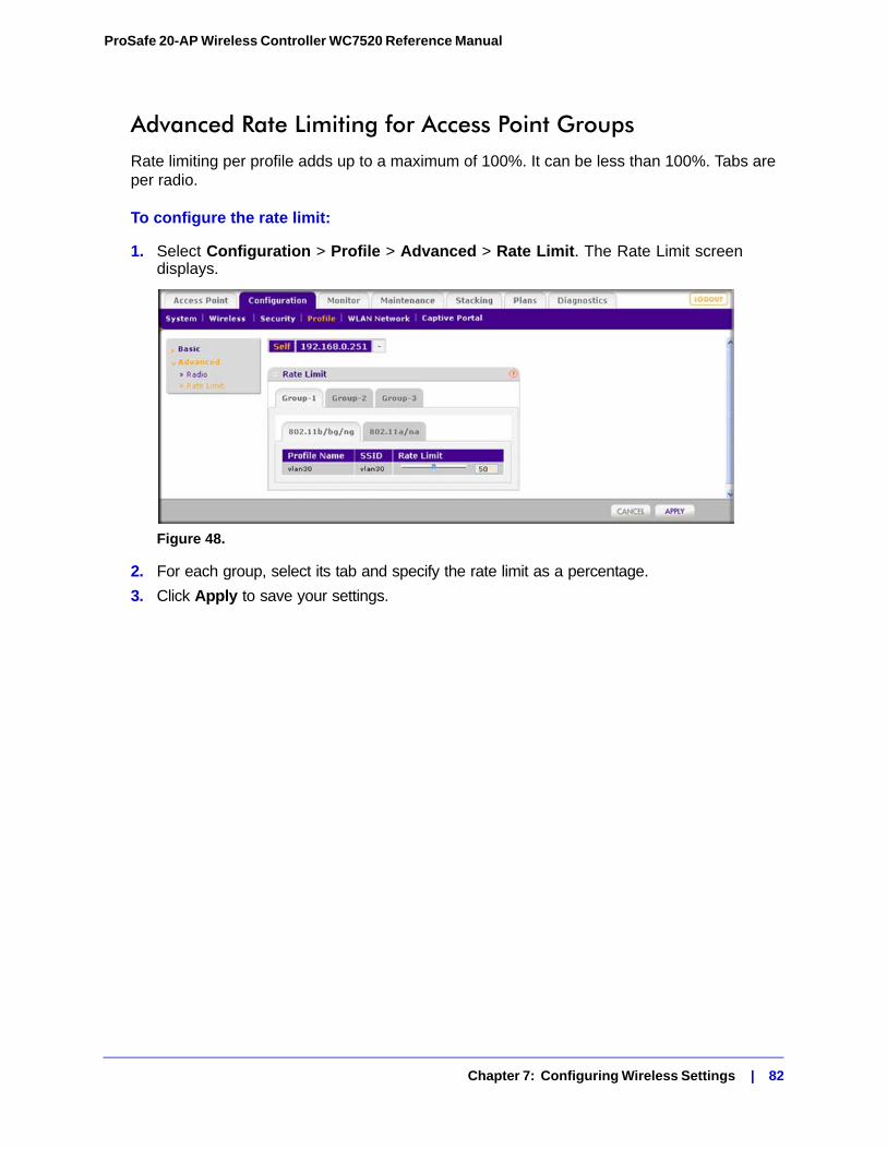
ProSafe 20-AP Wireless Controller WC7520 Reference Manual
Advanced Rate Limiting for Access Point GroupsRate limiting per profile adds up to a maximum of 100%. It can be less than 100%. Tabs are per radio.
To configure the rate limit:
1. Select Configuration > Profile > Advanced > Rate Limit. The Rate Limit screen displays.
Figure 48.
2. For each group, select its tab and specify the rate limit as a percentage.
3. Click Apply to save your settings.
Chapter 7: Configuring Wireless Settings | 82
8. Configuring Security and Wireless Security Profiles 8
This chapter includes the following sections:• Managing Wireless Security Profiles on this page
• Managing Rogue Access Points on page 89
• Managing MAC Authentication and MAC Authentication Groups on page 92
• Managing Authentication Servers and Authentication Server Groups on page 95
• Managing Guest Network Access on page 98
• Managing Users and Passwords on page 100
The wireless controller follows a configuration template called profile groups. Each access point at any instance operates using one profile group. A profile group includes all types of configuration that can be configured uniquely per access point, including 8 SSIDs per radio.
The basic configuration menu selections cater to simple networks. In these screens, configuration applies to all the access points by default. There is no concept of different profile groups. The advanced menu selections cater to large and complex networks. Here you can create separate policies per profile group such as the wireless-on/off schedule for access points, channel allocation schedule. The SSIDs can be different per profile group. This allows the administrator of a complex network to fine-tune the configuration to meet requirements.
It is important to know how to configure your network and decide which model fits better for your needs, basic or advanced. Once you follow one, it is easy to the use the same for all configuration pages.
Managing Wireless Security Profiles
Profiles are sets of configuration that can be applied to an access point. The configuration includes radio parameters, load balancing, and rate limit parameters. Each access point in managed mode is capable of supporting 8 profiles per radio. This means that the dual radio WNDAP350 access point can support 16 profiles in total.
Setting up profiles allows you to configure the WLAN network offline. Then, when the WLAN network is up and running, you can push the configuration onto managed access points. You can configure profiles and profile groups without worrying about the state of the access
Chapter 8: Configuring Security and Wireless Security Profiles | 83
ProSafe 20-AP Wireless Controller WC7520 Reference Manual
points. When the access points connect to the controller, the profile configurations are pushed onto the access points.
When developing profiles, take the following into consideration:
• Configuration templates for authentication server settings in case of LDAP/RADIUS and MAC ACL lists need to be done separately in their respective screens. (See Managing Authentication Servers and Authentication Server Groups on page 95 and Managing MAC Authentication and MAC Authentication Groups on page 92). Then you can assign one of the created security profiles to a particular profile.
• For faster set up you can clone a profile and rename it. Cloning copies all settings except the name and SSID.
• When the profiles have been created, you can use the WLAN Network screen to assign profile groups to the access points. See Managing Access Point Groups in the WLAN on page 66.
• Note that if an access point is removed from its building (someone takes it home or it is stolen) the access point does not retain the configuration that it received from the wireless controller. The configuration is not stored in memory on the access point.
Depending on your network needs, you can either use basic profile configuration, or advanced profile groups. Basic configuration works well for small-scale WLAN networks. Profile groups are useful for larger deployments.
Small-Scale WLAN NetworksFor small scale WLAN networks, you can use the basic configuration without profile groups. All access points belong to the same group and have the same configuration. For instance, an enterprise network comprising of a single floor building and having only a corporate and guest network would fit into this category.
Each radio can have multiple SSIDs. Each SSID can have one VLAN. This separates tunnels for each SSID. You would assign guests to a separate VLAN because guests typically access only the Internet, not the business network, and do not have peer-to-peer access.
Larger DeploymentsFor larger deployments, comprising of different set of WLAN networks, consider using the advanced profile option to create profile groups. The wireless controller supports up to 8 profile groups. Each profile group can contain up to 16 profiles for a dual-band access point, or 8 profiles for a single band access point.
Each radio can have multiple SSIDs. You can use naming conventions based on users such as Marketing, or use other conventions such as CompanyName15. One VLAN can be set up for each SSID. This separates tunnels for each SSID, though different profiles can share a VLAN. You would assign guests to a separate VLAN because guests typically access only the Internet, not the business network, and do not have peer-to-peer access.
Chapter 8: Configuring Security and Wireless Security Profiles | 84
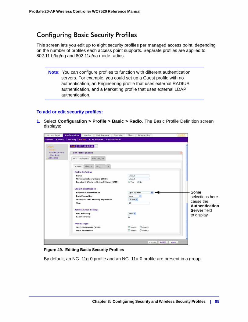
ProSafe 20-AP Wireless Controller WC7520 Reference Manual
Configuring Basic Security ProfilesThis screen lets you edit up to eight security profiles per managed access point, depending on the number of profiles each access point supports. Separate profiles are applied to 802.11 b/bg/ng and 802.11a/na mode radios.
Note: You can configure profiles to function with different authentication servers. For example, you could set up a Guest profile with no authentication, an Engineering profile that uses external RADIUS authentication, and a Marketing profile that uses external LDAP authentication.
To add or edit security profiles:
1. Select Configuration > Profile > Basic > Radio. The Basic Profile Definition screen displays:
Figure 49. Editing Basic Security Profiles
By default, an NG_11g-0 profile and an NG_11a-0 profile are present in a group.
Some selections herecause theAuthenticationServer fieldto display.
Chapter 8: Configuring Security and Wireless Security Profiles | 85

ProSafe 20-AP Wireless Controller WC7520 Reference Manual
Note: The selections available In the Network Authentication field are affected by the authentication server settings that you specify in the Authentication Server screen. See Configuring Basic MAC Authentication Settings on page 93. If the selection in the Network Authentication field requires authentication, an additional field, the corresponding Authentication Server field displays.
2. Use the tabs to select the wireless mode and the VLAN that you want to work with. Change the settings described in Table 22, Basic Security Profile Definition.
3. Click Apply to save your settings.
Table 23 shows the data encryption options based on network authentication.
Table 22. Basic Security Profile Definition
Setting Description
Name Enter a unique name to identify the Security Profile. This value can be up to 32 alphanumeric characters. Use meaningful profile names instead of the default names. The default profile names are Profile1, Profile2, ... Profile8.
Wireless Network Name (SSID) The name of the wireless network associated with this profile
Broadcast Wireless Network Name
Enabled by default. If set to Yes, the SSID is broadcast. If you disable broadcast of the SSID, only devices that have the correct SSID can connect to the access point.
Network Authentication The authentication type to be used. See Table 23, Network Authentication and Data Encryption on page 87.
Data Encryption The data encryption type to be used. The options available for data encryption depend on the network authentication settings. See Table 23, Network Authentication and Data Encryption on page 87.
Wireless Client Security Separation
If enabled, the associated wireless clients will not be able to communicate with each other. This feature is intended for hot spots and other public access situations.
VLAN The default VLAN ID to be associated with this security profile. This must match the VLAN ID used by other network devices.
Chapter 8: Configuring Security and Wireless Security Profiles | 86
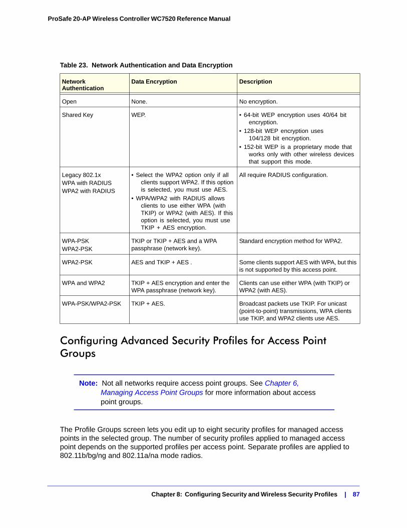
ProSafe 20-AP Wireless Controller WC7520 Reference Manual
Configuring Advanced Security Profiles for Access Point Groups
Note: Not all networks require access point groups. See Chapter 6, Managing Access Point Groups for more information about access point groups.
The Profile Groups screen lets you edit up to eight security profiles for managed access points in the selected group. The number of security profiles applied to managed access point depends on the supported profiles per access point. Separate profiles are applied to 802.11b/bg/ng and 802.11a/na mode radios.
Table 23. Network Authentication and Data Encryption
Network Authentication
Data Encryption Description
Open None. No encryption.
Shared Key WEP. • 64-bit WEP encryption uses 40/64 bit encryption.
• 128-bit WEP encryption uses 104/128 bit encryption.
• 152-bit WEP is a proprietary mode that works only with other wireless devices that support this mode.
Legacy 802.1xWPA with RADIUSWPA2 with RADIUS
• Select the WPA2 option only if all clients support WPA2. If this option is selected, you must use AES.
• WPA/WPA2 with RADIUS allows clients to use either WPA (with TKIP) or WPA2 (with AES). If this option is selected, you must use TKIP + AES encryption.
All require RADIUS configuration.
WPA-PSKWPA2-PSK
TKIP or TKIP + AES and a WPA passphrase (network key).
Standard encryption method for WPA2.
WPA2-PSK AES and TKIP + AES . Some clients support AES with WPA, but this is not supported by this access point.
WPA and WPA2 TKIP + AES encryption and enter the WPA passphrase (network key).
Clients can use either WPA (with TKIP) or WPA2 (with AES).
WPA-PSK/WPA2-PSK TKIP + AES. Broadcast packets use TKIP. For unicast (point-to-point) transmissions, WPA clients use TKIP, and WPA2 clients use AES.
Chapter 8: Configuring Security and Wireless Security Profiles | 87
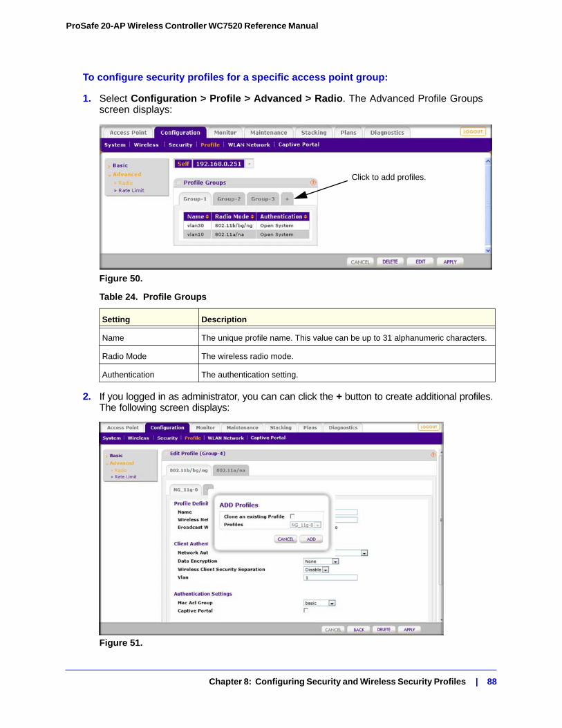
ProSafe 20-AP Wireless Controller WC7520 Reference Manual
To configure security profiles for a specific access point group:
1. Select Configuration > Profile > Advanced > Radio. The Advanced Profile Groups screen displays:
Figure 50.
2. If you logged in as administrator, you can can click the + button to create additional profiles. The following screen displays:
Figure 51.
Table 24. Profile Groups
Setting Description
Name The unique profile name. This value can be up to 31 alphanumeric characters.
Radio Mode The wireless radio mode.
Authentication The authentication setting.
Click to add profiles.
Chapter 8: Configuring Security and Wireless Security Profiles | 88
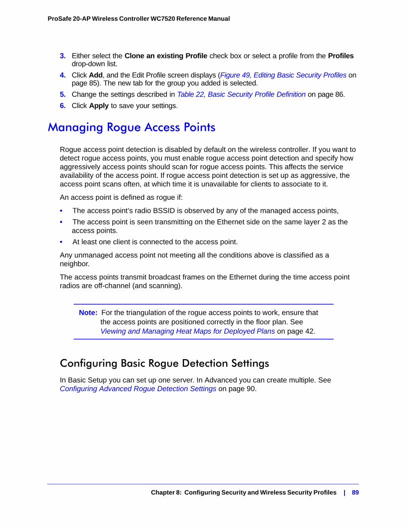
ProSafe 20-AP Wireless Controller WC7520 Reference Manual
3. Either select the Clone an existing Profile check box or select a profile from the Profiles drop-down list.
4. Click Add, and the Edit Profile screen displays (Figure 49, Editing Basic Security Profiles on page 85). The new tab for the group you added is selected.
5. Change the settings described in Table 22, Basic Security Profile Definition on page 86.
6. Click Apply to save your settings.
Managing Rogue Access Points
Rogue access point detection is disabled by default on the wireless controller. If you want to detect rogue access points, you must enable rogue access point detection and specify how aggressively access points should scan for rogue access points. This affects the service availability of the access point. If rogue access point detection is set up as aggressive, the access point scans often, at which time it is unavailable for clients to associate to it.
An access point is defined as rogue if:
• The access point’s radio BSSID is observed by any of the managed access points,
• The access point is seen transmitting on the Ethernet side on the same layer 2 as the access points.
• At least one client is connected to the access point.
Any unmanaged access point not meeting all the conditions above is classified as a neighbor.
The access points transmit broadcast frames on the Ethernet during the time access point radios are off-channel (and scanning).
Note: For the triangulation of the rogue access points to work, ensure that the access points are positioned correctly in the floor plan. See Viewing and Managing Heat Maps for Deployed Plans on page 42.
Configuring Basic Rogue Detection SettingsIn Basic Setup you can set up one server. In Advanced you can create multiple. See Configuring Advanced Rogue Detection Settings on page 90.
Chapter 8: Configuring Security and Wireless Security Profiles | 89
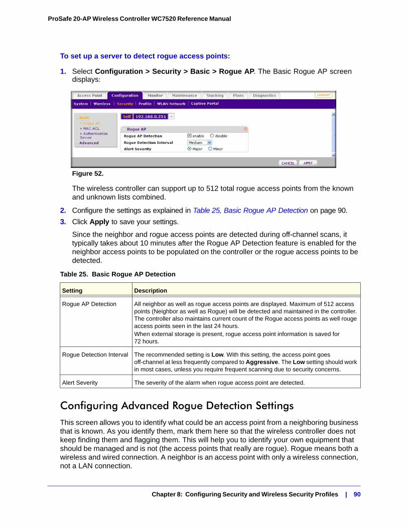
ProSafe 20-AP Wireless Controller WC7520 Reference Manual
To set up a server to detect rogue access points:
1. Select Configuration > Security > Basic > Rogue AP. The Basic Rogue AP screen displays:
Figure 52.
The wireless controller can support up to 512 total rogue access points from the known and unknown lists combined.
2. Configure the settings as explained in Table 25, Basic Rogue AP Detection on page 90.
3. Click Apply to save your settings.
Since the neighbor and rogue access points are detected during off-channel scans, it typically takes about 10 minutes after the Rogue AP Detection feature is enabled for the neighbor access points to be populated on the controller or the rogue access points to be detected.
Configuring Advanced Rogue Detection SettingsThis screen allows you to identify what could be an access point from a neighboring business that is known. As you identify them, mark them here so that the wireless controller does not keep finding them and flagging them. This will help you to identify your own equipment that should be managed and is not (the access points that really are rogue). Rogue means both a wireless and wired connection. A neighbor is an access point with only a wireless connection, not a LAN connection.
Table 25. Basic Rogue AP Detection
Setting Description
Rogue AP Detection All neighbor as well as rogue access points are displayed. Maximum of 512 access points (Neighbor as well as Rogue) will be detected and maintained in the controller. The controller also maintains current count of the Rogue access points as well rouge access points seen in the last 24 hours.When external storage is present, rogue access point information is saved for 72 hours.
Rogue Detection Interval The recommended setting is Low. With this setting, the access point goes off-channel at less frequently compared to Aggressive. The Low setting should work in most cases, unless you require frequent scanning due to security concerns.
Alert Severity The severity of the alarm when rogue access point are detected.
Chapter 8: Configuring Security and Wireless Security Profiles | 90
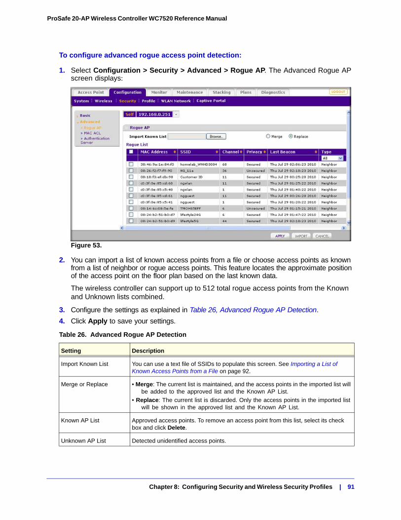
ProSafe 20-AP Wireless Controller WC7520 Reference Manual
To configure advanced rogue access point detection:
1. Select Configuration > Security > Advanced > Rogue AP. The Advanced Rogue AP screen displays:
Figure 53.
2. You can import a list of known access points from a file or choose access points as known from a list of neighbor or rogue access points. This feature locates the approximate position of the access point on the floor plan based on the last known data.
The wireless controller can support up to 512 total rogue access points from the Known and Unknown lists combined.
3. Configure the settings as explained in Table 26, Advanced Rogue AP Detection.
4. Click Apply to save your settings.
Table 26. Advanced Rogue AP Detection
Setting Description
Import Known List You can use a text file of SSIDs to populate this screen. See Importing a List of Known Access Points from a File on page 92.
Merge or Replace • Merge: The current list is maintained, and the access points in the imported list will be added to the approved list and the Known AP List.
• Replace: The current list is discarded. Only the access points in the imported list will be shown in the approved list and the Known AP List.
Known AP List Approved access points. To remove an access point from this list, select its check box and click Delete.
Unknown AP List Detected unidentified access points.
Chapter 8: Configuring Security and Wireless Security Profiles | 91
ProSafe 20-AP Wireless Controller WC7520 Reference Manual
Importing a List of Known Access Points from a FileYou can import a list of known access points from a saved file. To do this, create a text file that includes the MAC address of each access point. This file must be a simple text file with one MAC address per line.
To import a list of known access points from a file:
1. Create a text file that includes a list of MAC addresses for the access points. Each MAC address should be on a separate line with hard returns between lines as shown in the following example:00:00:11:11:22:29 00:00:11:11:22:28 00:00:11:11:22:27 00:00:11:11:22:26 00:00:11:11:22:25
2. Select Configuration > Security > Advanced > Rogue AP to go to the Rogue AP screen.
3. Click Browse and select the file containing the list of approved MAC addresses.
4. Select the radio button that corresponds to your needs:
• Merge: This adds known access points without removing those that are already shown in this screen.
• Replace: Replace the known access points shown in this screen with the access points from the list in the text file.
5. Click Import.
6. Click Apply so that your changes take effect.
Managing MAC Authentication and MAC Authentication Groups
MAC authentication lets you block the network access privilege of the specified stations with the wireless controller–managed access point. The settings are applied only to managed access points.
Chapter 8: Configuring Security and Wireless Security Profiles | 92
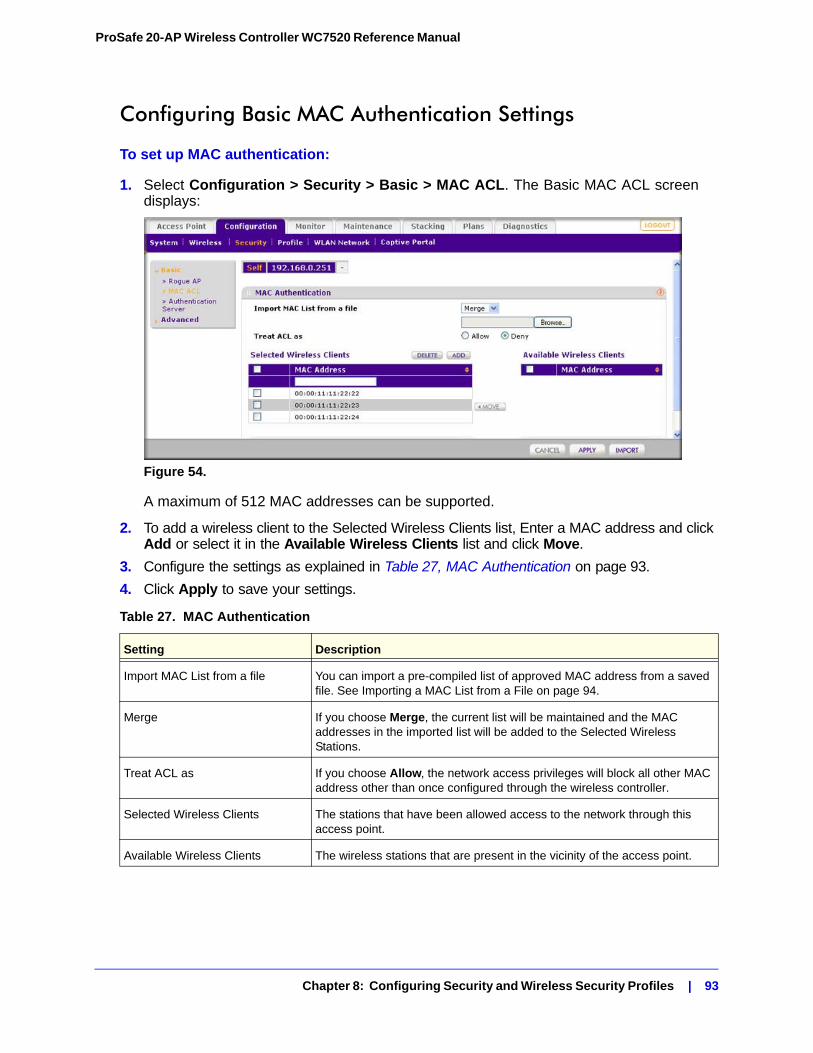
ProSafe 20-AP Wireless Controller WC7520 Reference Manual
Configuring Basic MAC Authentication Settings
To set up MAC authentication:
1. Select Configuration > Security > Basic > MAC ACL. The Basic MAC ACL screen displays:
Figure 54.
A maximum of 512 MAC addresses can be supported.
2. To add a wireless client to the Selected Wireless Clients list, Enter a MAC address and click Add or select it in the Available Wireless Clients list and click Move.
3. Configure the settings as explained in Table 27, MAC Authentication on page 93.
4. Click Apply to save your settings.
Table 27. MAC Authentication
Setting Description
Import MAC List from a file You can import a pre-compiled list of approved MAC address from a saved file. See Importing a MAC List from a File on page 94.
Merge If you choose Merge, the current list will be maintained and the MAC addresses in the imported list will be added to the Selected Wireless Stations.
Treat ACL as If you choose Allow, the network access privileges will block all other MAC address other than once configured through the wireless controller.
Selected Wireless Clients The stations that have been allowed access to the network through this access point.
Available Wireless Clients The wireless stations that are present in the vicinity of the access point.
Chapter 8: Configuring Security and Wireless Security Profiles | 93
ProSafe 20-AP Wireless Controller WC7520 Reference Manual
Importing a MAC List from a FileYou can import a pre-compiled list of approved MAC address from a saved file. This file must be a simple text file with one MAC address per line.
To import a MAC list from a file:
1. Create a text file that includes a list of approved MAC addresses. Each MAC address should be on a separate line with hard returns between lines as shown in the following example:00:00:11:11:22:29 00:00:11:11:22:28 00:00:11:11:22:27 00:00:11:11:22:26 00:00:11:11:22:25
2. Select Configuration > Security > Basic > MAC ACL to go to the MAC Authentication screen.
3. Click Browse and select the file containing the list of approved MAC addresses.
4. If you want to add approved MAC addresses without removing those that are already shown in this screen, select Merge in the Import MAC list from a file field.
5. Click Import.
6. Click Apply so that your changes take effect.
Configuring MAC Authentication Settings for GroupsThis lets you block network access privilege of the specified stations through a specific group of managed wireless access points.
Note: Many networks do not require access point groups. See Managing Access Point Groups in Chapter 6 for more information about access point groups.
Chapter 8: Configuring Security and Wireless Security Profiles | 94
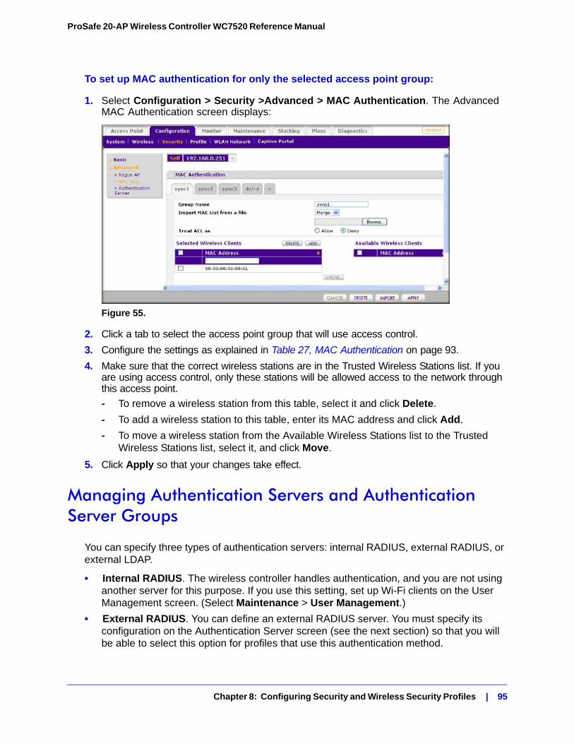
ProSafe 20-AP Wireless Controller WC7520 Reference Manual
To set up MAC authentication for only the selected access point group:
1. Select Configuration > Security >Advanced > MAC Authentication. The Advanced MAC Authentication screen displays:
Figure 55.
2. Click a tab to select the access point group that will use access control.
3. Configure the settings as explained in Table 27, MAC Authentication on page 93.
4. Make sure that the correct wireless stations are in the Trusted Wireless Stations list. If you are using access control, only these stations will be allowed access to the network through this access point.
- To remove a wireless station from this table, select it and click Delete.
- To add a wireless station to this table, enter its MAC address and click Add.
- To move a wireless station from the Available Wireless Stations list to the Trusted Wireless Stations list, select it, and click Move.
5. Click Apply so that your changes take effect.
Managing Authentication Servers and Authentication Server Groups
You can specify three types of authentication servers: internal RADIUS, external RADIUS, or external LDAP.
• Internal RADIUS. The wireless controller handles authentication, and you are not using another server for this purpose. If you use this setting, set up Wi-Fi clients on the User Management screen. (Select Maintenance > User Management.)
• External RADIUS. You can define an external RADIUS server. You must specify its configuration on the Authentication Server screen (see the next section) so that you will be able to select this option for profiles that use this authentication method.
Chapter 8: Configuring Security and Wireless Security Profiles | 95
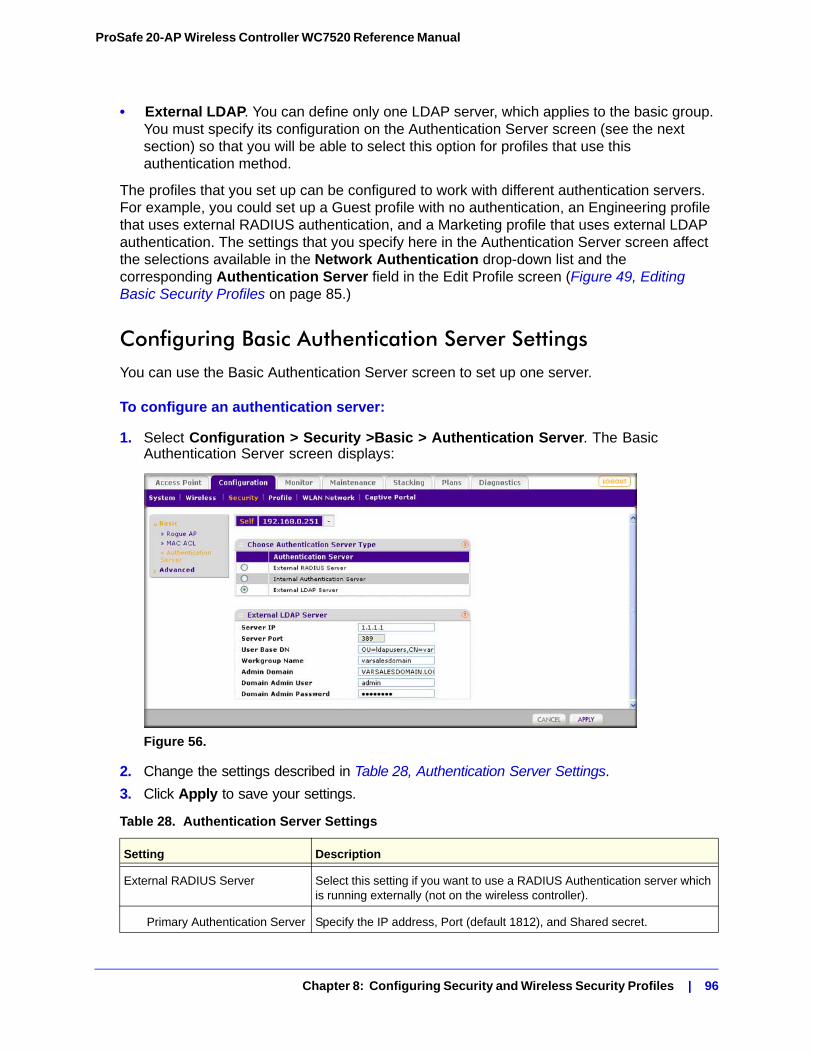
ProSafe 20-AP Wireless Controller WC7520 Reference Manual
• External LDAP. You can define only one LDAP server, which applies to the basic group. You must specify its configuration on the Authentication Server screen (see the next section) so that you will be able to select this option for profiles that use this authentication method.
The profiles that you set up can be configured to work with different authentication servers. For example, you could set up a Guest profile with no authentication, an Engineering profile that uses external RADIUS authentication, and a Marketing profile that uses external LDAP authentication. The settings that you specify here in the Authentication Server screen affect the selections available in the Network Authentication drop-down list and the corresponding Authentication Server field in the Edit Profile screen (Figure 49, Editing Basic Security Profiles on page 85.)
Configuring Basic Authentication Server SettingsYou can use the Basic Authentication Server screen to set up one server.
To configure an authentication server:
1. Select Configuration > Security >Basic > Authentication Server. The Basic Authentication Server screen displays:
Figure 56.
2. Change the settings described in Table 28, Authentication Server Settings.
3. Click Apply to save your settings.
Table 28. Authentication Server Settings
Setting Description
External RADIUS Server Select this setting if you want to use a RADIUS Authentication server which is running externally (not on the wireless controller).
Primary Authentication Server Specify the IP address, Port (default 1812), and Shared secret.
Chapter 8: Configuring Security and Wireless Security Profiles | 96
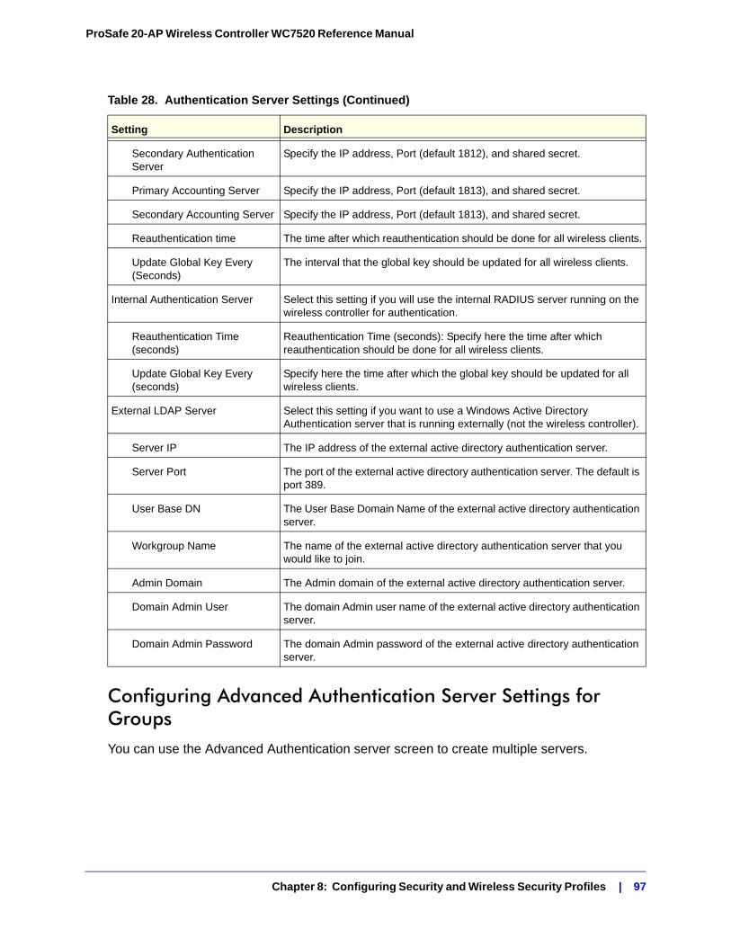
ProSafe 20-AP Wireless Controller WC7520 Reference Manual
Configuring Advanced Authentication Server Settings for GroupsYou can use the Advanced Authentication server screen to create multiple servers.
Secondary Authentication Server
Specify the IP address, Port (default 1812), and shared secret.
Primary Accounting Server Specify the IP address, Port (default 1813), and shared secret.
Secondary Accounting Server Specify the IP address, Port (default 1813), and shared secret.
Reauthentication time The time after which reauthentication should be done for all wireless clients.
Update Global Key Every (Seconds)
The interval that the global key should be updated for all wireless clients.
Internal Authentication Server Select this setting if you will use the internal RADIUS server running on the wireless controller for authentication.
Reauthentication Time (seconds)
Reauthentication Time (seconds): Specify here the time after which reauthentication should be done for all wireless clients.
Update Global Key Every (seconds)
Specify here the time after which the global key should be updated for all wireless clients.
External LDAP Server Select this setting if you want to use a Windows Active Directory Authentication server that is running externally (not the wireless controller).
Server IP The IP address of the external active directory authentication server.
Server Port The port of the external active directory authentication server. The default is port 389.
User Base DN The User Base Domain Name of the external active directory authentication server.
Workgroup Name The name of the external active directory authentication server that you would like to join.
Admin Domain The Admin domain of the external active directory authentication server.
Domain Admin User The domain Admin user name of the external active directory authentication server.
Domain Admin Password The domain Admin password of the external active directory authentication server.
Table 28. Authentication Server Settings (Continued)
Setting Description
Chapter 8: Configuring Security and Wireless Security Profiles | 97
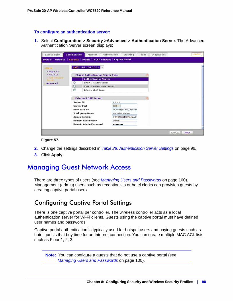
ProSafe 20-AP Wireless Controller WC7520 Reference Manual
To configure an authentication server:
1. Select Configuration > Security >Advanced > Authentication Server. The Advanced Authentication Server screen displays:
Figure 57.
2. Change the settings described in Table 28, Authentication Server Settings on page 96.
3. Click Apply.
Managing Guest Network Access
There are three types of users (see Managing Users and Passwords on page 100). Management (admin) users such as receptionists or hotel clerks can provision guests by creating captive portal users.
Configuring Captive Portal SettingsThere is one captive portal per controller. The wireless controller acts as a local authentication server for Wi-Fi clients. Guests using the captive portal must have defined user names and passwords.
Captive portal authentication is typically used for hotspot users and paying guests such as hotel guests that buy time for an Internet connection. You can create multiple MAC ACL lists, such as Floor 1, 2, 3.
Note: You can configure a guests that do not use a captive portal (see Managing Users and Passwords on page 100).
Chapter 8: Configuring Security and Wireless Security Profiles | 98
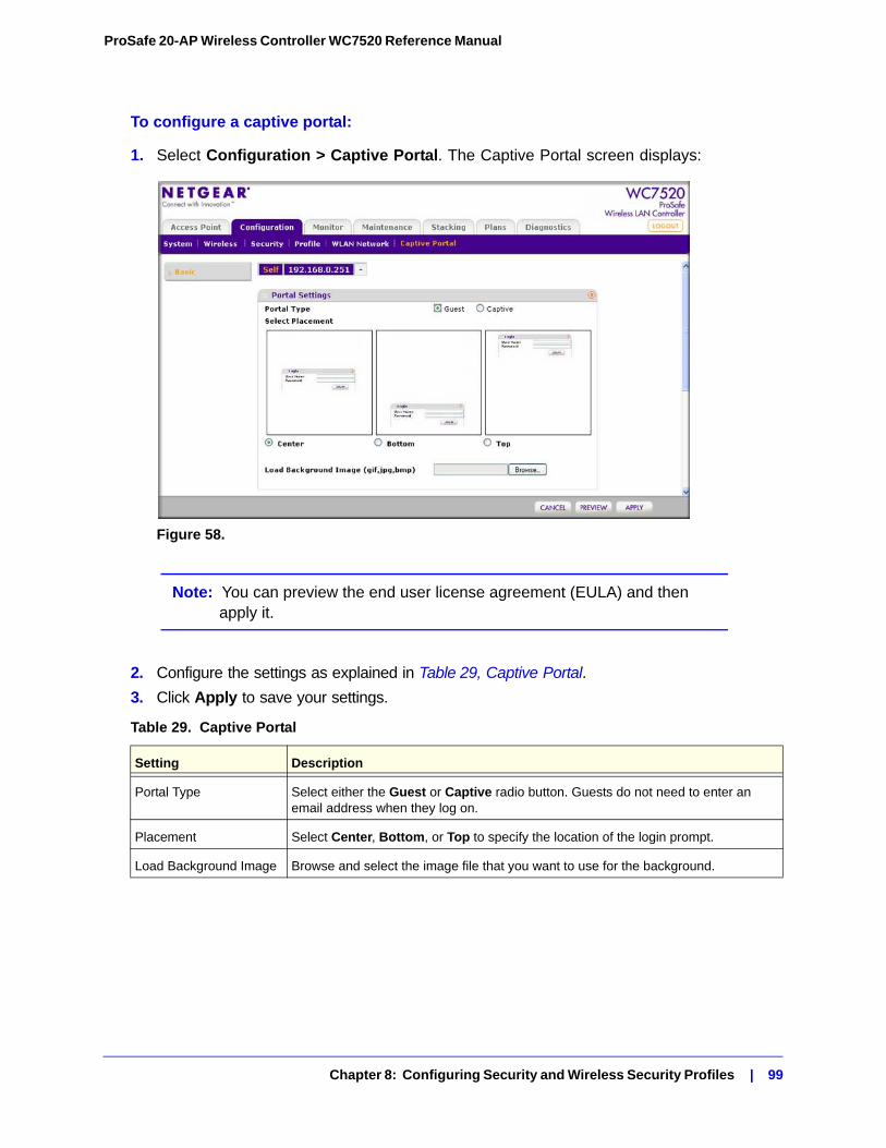
ProSafe 20-AP Wireless Controller WC7520 Reference Manual
To configure a captive portal:
1. Select Configuration > Captive Portal. The Captive Portal screen displays:
Figure 58.
Note: You can preview the end user license agreement (EULA) and then apply it.
2. Configure the settings as explained in Table 29, Captive Portal.
3. Click Apply to save your settings.
Table 29. Captive Portal
Setting Description
Portal Type Select either the Guest or Captive radio button. Guests do not need to enter an email address when they log on.
Placement Select Center, Bottom, or Top to specify the location of the login prompt.
Load Background Image Browse and select the image file that you want to use for the background.
Chapter 8: Configuring Security and Wireless Security Profiles | 99
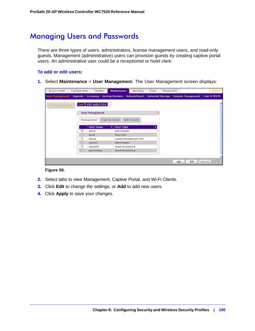
ProSafe 20-AP Wireless Controller WC7520 Reference Manual
Managing Users and Passwords
There are three types of users: administrators, license management users, and read-only guests. Management (administrative) users can provision guests by creating captive portal users. An administrative user could be a receptionist or hotel clerk.
To add or edit users:
1. Select Maintenance > User Management. The User Management screen displays:
Figure 59.
2. Select tabs to view Management, Captive Portal, and Wi-Fi Clients.
3. Click Edit to change the settings, or Add to add new users.
4. Click Apply to save your changes.
Chapter 8: Configuring Security and Wireless Security Profiles | 100
9. Maintaining the Controller 9
This chapter includes the following sections:• Managing the Configuration File on this page
• Rebooting or Resetting the Wireless Controller on page 105
• Rebooting Access Points on page 107
• Managing External Storage on page 107
• Managing Remote Access on page 108
• Viewing Alerts and Events and Saving Logs on page 110
• Managing Licenses on page 115
Managing the Configuration File
This section includes the following subsections:
• Backing Up and Restoring the Configuration File on this page
• Upgrading the Configuration File on page 103
The configuration settings of the wireless controller are stored in a configuration file on the wireless controller. This file can be saved (backed up) to a computer, retrieved (restored) from the computer, or cleared to factory default settings.
Once the wireless controller is installed and works correctly, make a backup of the configuration file to a computer. If necessary, you can later restore the wireless controller settings from this file.
Chapter 9: Maintaining the Controller | 101
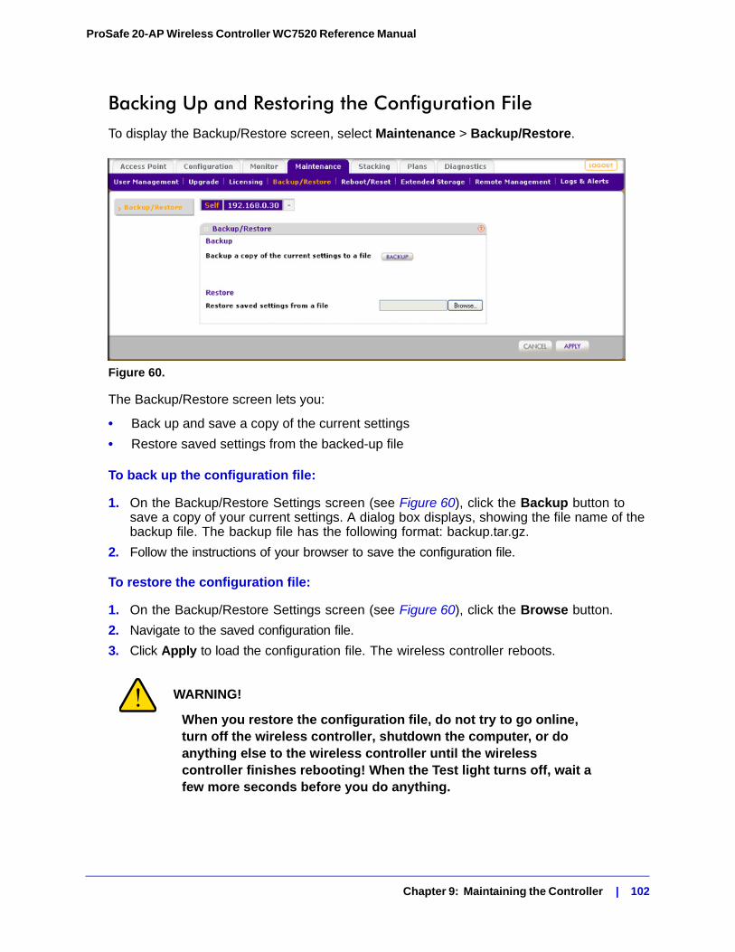
ProSafe 20-AP Wireless Controller WC7520 Reference Manual
Backing Up and Restoring the Configuration FileTo display the Backup/Restore screen, select Maintenance > Backup/Restore.
Figure 60.
The Backup/Restore screen lets you:
• Back up and save a copy of the current settings
• Restore saved settings from the backed-up file
To back up the configuration file:
1. On the Backup/Restore Settings screen (see Figure 60), click the Backup button to save a copy of your current settings. A dialog box displays, showing the file name of the backup file. The backup file has the following format: backup.tar.gz.
2. Follow the instructions of your browser to save the configuration file.
To restore the configuration file:
1. On the Backup/Restore Settings screen (see Figure 60), click the Browse button.
2. Navigate to the saved configuration file.
3. Click Apply to load the configuration file. The wireless controller reboots.
WARNING!
When you restore the configuration file, do not try to go online, turn off the wireless controller, shutdown the computer, or do anything else to the wireless controller until the wireless controller finishes rebooting! When the Test light turns off, wait a few more seconds before you do anything.
Chapter 9: Maintaining the Controller | 102
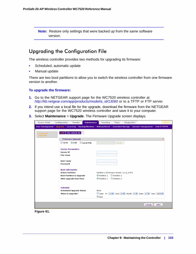
ProSafe 20-AP Wireless Controller WC7520 Reference Manual
Note: Restore only settings that were backed up from the same software version.
Upgrading the Configuration FileThe wireless controller provides two methods for upgrading its firmware:
• Scheduled, automatic update
• Manual update
There are two boot partitions to allow you to switch the wireless controller from one firmware version to another.
To upgrade the firmware:
1. Go to the NETGEAR support page for the WC7520 wireless controller at http://kb.netgear.com/app/products/model/a_id/13060 or to a TFTP or FTP server.
2. If you intend use a local file for the upgrade, download the firmware from the NETGEAR support page for the WC7520 wireless controller and save it to your computer.
3. Select Maintenance > Upgrade. The Firmware Upgrade screen displays.
Figure 61.
Chapter 9: Maintaining the Controller | 103
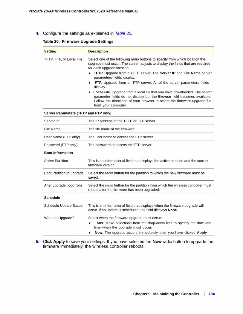
ProSafe 20-AP Wireless Controller WC7520 Reference Manual
4. Configure the settings as explained in Table 30.
5. Click Apply to save your settings. If you have selected the Now radio button to upgrade the firmware immediately, the wireless controller reboots.
Table 30. Firmware Upgrade Settings
Setting Description
TFTP, FTP, or Local File Select one of the following radio buttons to specify from which location the upgrade must occur. The screen adjusts to display the fields that are required for each upgrade location.
• TFTP. Upgrade from a TFTP server. The Server IP and File Name server parameters fields display.
• FTP. Upgrade from an FTP server. All of the server parameters fields display.
• Local File. Upgrade from a local file that you have downloaded. The server parameter fields do not display but the Browse field becomes available. Follow the directions of your browser to select the firmware upgrade file from your computer.
Server Parameters (TFTP and FTP only)
Server IP The IP address of the TFTP or FTP server.
File Name The file name of the firmware.
User Name (FTP only) The user name to access the FTP server.
Password (FTP only) The password to access the FTP server.
Boot Information
Active Partition This is an informational field that displays the active partition and the current firmware version.
Boot Partition to upgrade Select the radio button for the partition to which the new firmware must be saved.
After upgrade boot from Select the radio button for the partition from which the wireless controller must reboot after the firmware has been upgraded.
Schedule
Schedule Update Status This is an informational field that displays when the firmware upgrade will occur. If no update is scheduled, the field displays None.
When to Upgrade? Select when the firmware upgrade must occur:
• Later. Make selections from the drop-down lists to specify the date and time when the upgrade must occur.
• Now. The upgrade occurs immediately after you have clicked Apply.
Chapter 9: Maintaining the Controller | 104
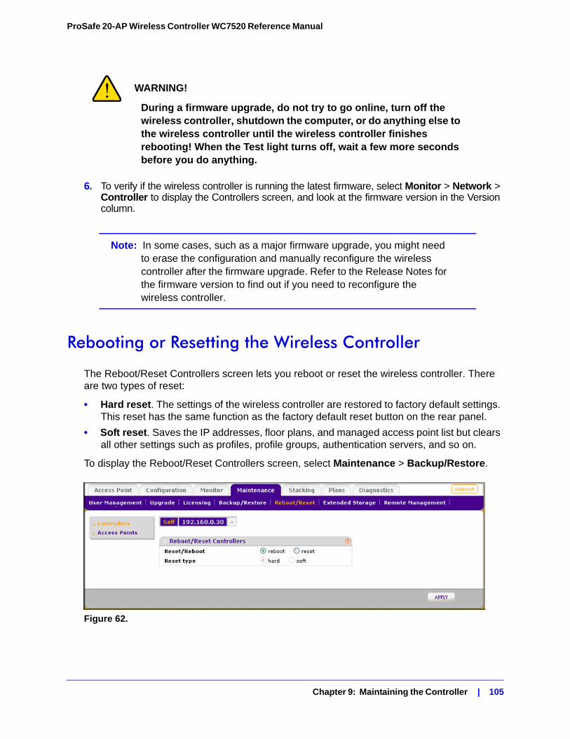
ProSafe 20-AP Wireless Controller WC7520 Reference Manual
WARNING!
During a firmware upgrade, do not try to go online, turn off the wireless controller, shutdown the computer, or do anything else to the wireless controller until the wireless controller finishes rebooting! When the Test light turns off, wait a few more seconds before you do anything.
6. To verify if the wireless controller is running the latest firmware, select Monitor > Network > Controller to display the Controllers screen, and look at the firmware version in the Version column.
Note: In some cases, such as a major firmware upgrade, you might need to erase the configuration and manually reconfigure the wireless controller after the firmware upgrade. Refer to the Release Notes for the firmware version to find out if you need to reconfigure the wireless controller.
Rebooting or Resetting the Wireless Controller
The Reboot/Reset Controllers screen lets you reboot or reset the wireless controller. There are two types of reset:
• Hard reset. The settings of the wireless controller are restored to factory default settings. This reset has the same function as the factory default reset button on the rear panel.
• Soft reset. Saves the IP addresses, floor plans, and managed access point list but clears all other settings such as profiles, profile groups, authentication servers, and so on.
To display the Reboot/Reset Controllers screen, select Maintenance > Backup/Restore.
Figure 62.
Chapter 9: Maintaining the Controller | 105
ProSafe 20-AP Wireless Controller WC7520 Reference Manual
To reboot the wireless controller:
1. Select the reboot radio button.
2. Click Apply. The wireless controller reboots. The reboot process is complete after several minutes when the Test LED on the front panel goes off.
To reset the wireless controller:
1. Select the reset radio button.
2. Select one of the following radio buttons to specify a hard reset or soft reset:
- hard. Restore the factory default settings (that are listed in Appendix A, Factory Default Settings and Technical Specifications) to the wireless controller.
- soft. Clear all settings except for the IP addresses, floor plans, and managed access point list.
3. Click Apply. If you selected a hard reset, the wireless controller reboots.
Note: Restoring the factory default settings of the wireless controller does not restore the settings of the access points that are managed by the wireless controller.
WARNING!
If you perform a hard reset, do not try to go online, turn off the wireless controller, shutdown the computer, or do anything else to the wireless controller until the wireless controller finishes rebooting! When the Test light turns off, wait a few more seconds before you do anything.
Chapter 9: Maintaining the Controller | 106
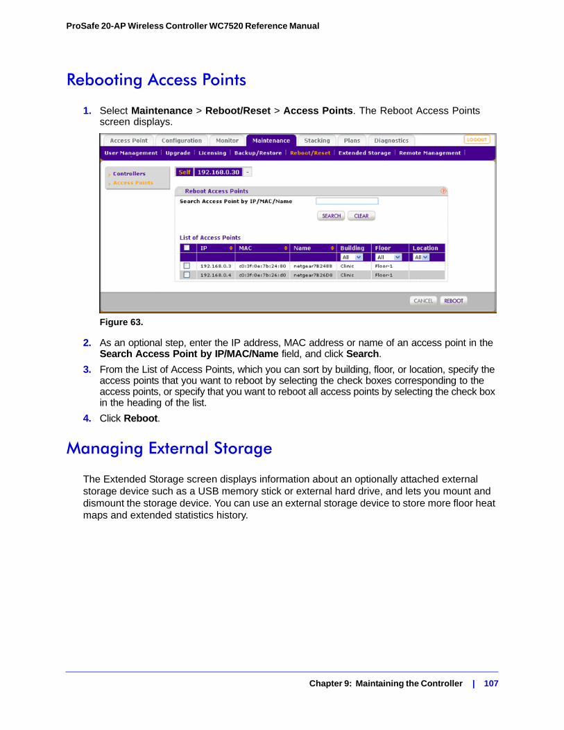
ProSafe 20-AP Wireless Controller WC7520 Reference Manual
Rebooting Access Points
1. Select Maintenance > Reboot/Reset > Access Points. The Reboot Access Points screen displays.
Figure 63.
2. As an optional step, enter the IP address, MAC address or name of an access point in the Search Access Point by IP/MAC/Name field, and click Search.
3. From the List of Access Points, which you can sort by building, floor, or location, specify the access points that you want to reboot by selecting the check boxes corresponding to the access points, or specify that you want to reboot all access points by selecting the check box in the heading of the list.
4. Click Reboot.
Managing External Storage
The Extended Storage screen displays information about an optionally attached external storage device such as a USB memory stick or external hard drive, and lets you mount and dismount the storage device. You can use an external storage device to store more floor heat maps and extended statistics history.
Chapter 9: Maintaining the Controller | 107
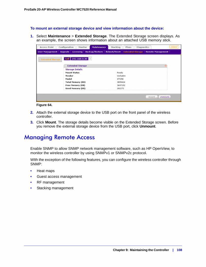
ProSafe 20-AP Wireless Controller WC7520 Reference Manual
To mount an external storage device and view information about the device:
1. Select Maintenance > Extended Storage. The Extended Storage screen displays. As an example, the screen shows information about an attached USB memory stick.
Figure 64.
2. Attach the external storage device to the USB port on the front panel of the wireless controller.
3. Click Mount. The storage details become visible on the Extended Storage screen. Before you remove the external storage device from the USB port, click Unmount.
Managing Remote Access
Enable SNMP to allow SNMP network management software, such as HP OpenView, to monitor the wireless controller by using SNMPv1 or SNMPv2c protocol.
WIth the exception of the following features, you can configure the wireless controller through SNMP:
• Heat maps
• Guest access management
• RF management
• Stacking management
Chapter 9: Maintaining the Controller | 108
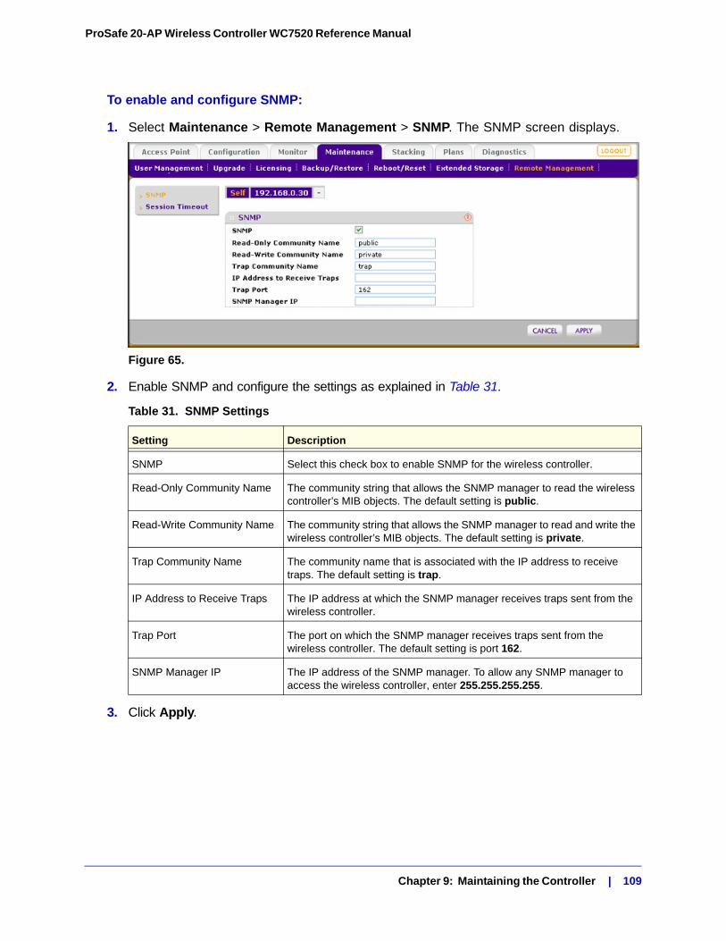
ProSafe 20-AP Wireless Controller WC7520 Reference Manual
To enable and configure SNMP:
1. Select Maintenance > Remote Management > SNMP. The SNMP screen displays.
Figure 65.
2. Enable SNMP and configure the settings as explained in Table 31.
3. Click Apply.
Table 31. SNMP Settings
Setting Description
SNMP Select this check box to enable SNMP for the wireless controller.
Read-Only Community Name The community string that allows the SNMP manager to read the wireless controller’s MIB objects. The default setting is public.
Read-Write Community Name The community string that allows the SNMP manager to read and write the wireless controller’s MIB objects. The default setting is private.
Trap Community Name The community name that is associated with the IP address to receive traps. The default setting is trap.
IP Address to Receive Traps The IP address at which the SNMP manager receives traps sent from the wireless controller.
Trap Port The port on which the SNMP manager receives traps sent from the wireless controller. The default setting is port 162.
SNMP Manager IP The IP address of the SNMP manager. To allow any SNMP manager to access the wireless controller, enter 255.255.255.255.
Chapter 9: Maintaining the Controller | 109
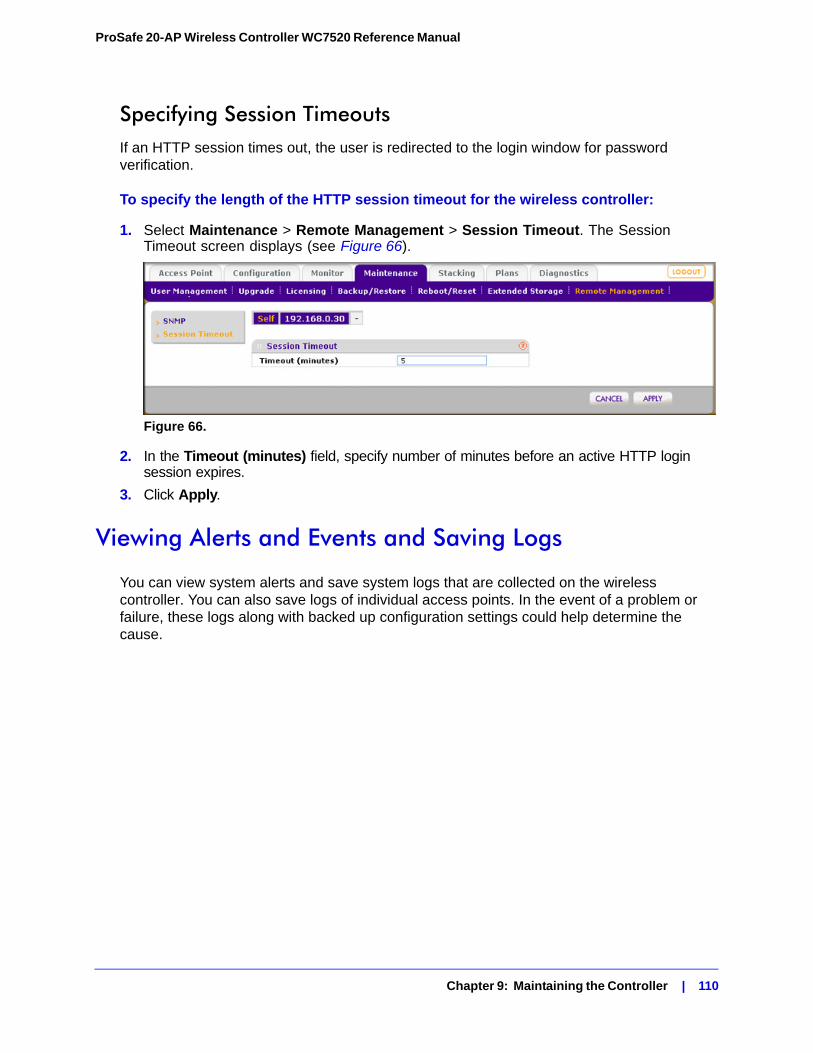
ProSafe 20-AP Wireless Controller WC7520 Reference Manual
Specifying Session TimeoutsIf an HTTP session times out, the user is redirected to the login window for password verification.
To specify the length of the HTTP session timeout for the wireless controller:
1. Select Maintenance > Remote Management > Session Timeout. The Session Timeout screen displays (see Figure 66).
Figure 66.
2. In the Timeout (minutes) field, specify number of minutes before an active HTTP login session expires.
3. Click Apply.
Viewing Alerts and Events and Saving Logs
You can view system alerts and save system logs that are collected on the wireless controller. You can also save logs of individual access points. In the event of a problem or failure, these logs along with backed up configuration settings could help determine the cause.
Chapter 9: Maintaining the Controller | 110
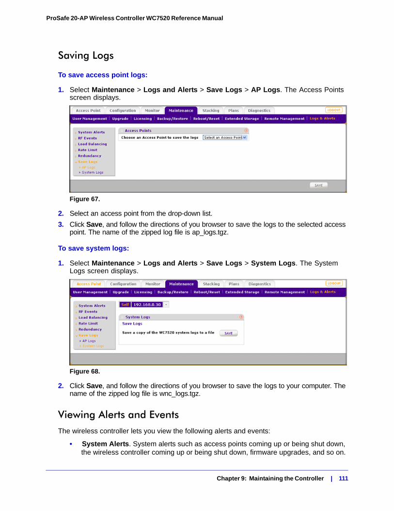
ProSafe 20-AP Wireless Controller WC7520 Reference Manual
Saving Logs
To save access point logs:
1. Select Maintenance > Logs and Alerts > Save Logs > AP Logs. The Access Points screen displays.
Figure 67.
2. Select an access point from the drop-down list.
3. Click Save, and follow the directions of you browser to save the logs to the selected access point. The name of the zipped log file is ap_logs.tgz.
To save system logs:
1. Select Maintenance > Logs and Alerts > Save Logs > System Logs. The System Logs screen displays.
Figure 68.
2. Click Save, and follow the directions of you browser to save the logs to your computer. The name of the zipped log file is wnc_logs.tgz.
Viewing Alerts and EventsThe wireless controller lets you view the following alerts and events:
• System Alerts. System alerts such as access points coming up or being shut down, the wireless controller coming up or being shut down, firmware upgrades, and so on.
Chapter 9: Maintaining the Controller | 111
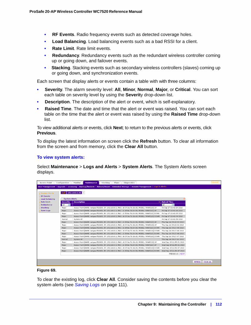
ProSafe 20-AP Wireless Controller WC7520 Reference Manual
• RF Events. Radio frequency events such as detected coverage holes.
• Load Balancing. Load balancing events such as a bad RSSI for a client.
• Rate Limit. Rate limit events.
• Redundancy. Redundancy events such as the redundant wireless controller coming up or going down, and failover events.
• Stacking. Stacking events such as secondary wireless controllers (slaves) coming up or going down, and synchronization events.
Each screen that display alerts or events contain a table with with three columns:
• Severity. The alarm severity level: All, Minor, Normal, Major, or Critical. You can sort each table on severity level by using the Severity drop-down list.
• Description. The description of the alert or event, which is self-explanatory.
• Raised Time. The date and time that the alert or event was raised. You can sort each table on the time that the alert or event was raised by using the Raised Time drop-down list.
To view additional alerts or events, click Next; to return to the previous alerts or events, click Previous.
To display the latest information on screen click the Refresh button. To clear all information from the screen and from memory, click the Clear All button.
To view system alerts:
Select Maintenance > Logs and Alerts > System Alerts. The System Alerts screen displays.
Figure 69.
To clear the existing log, click Clear All. Consider saving the contents before you clear the system alerts (see Saving Logs on page 111).
Chapter 9: Maintaining the Controller | 112
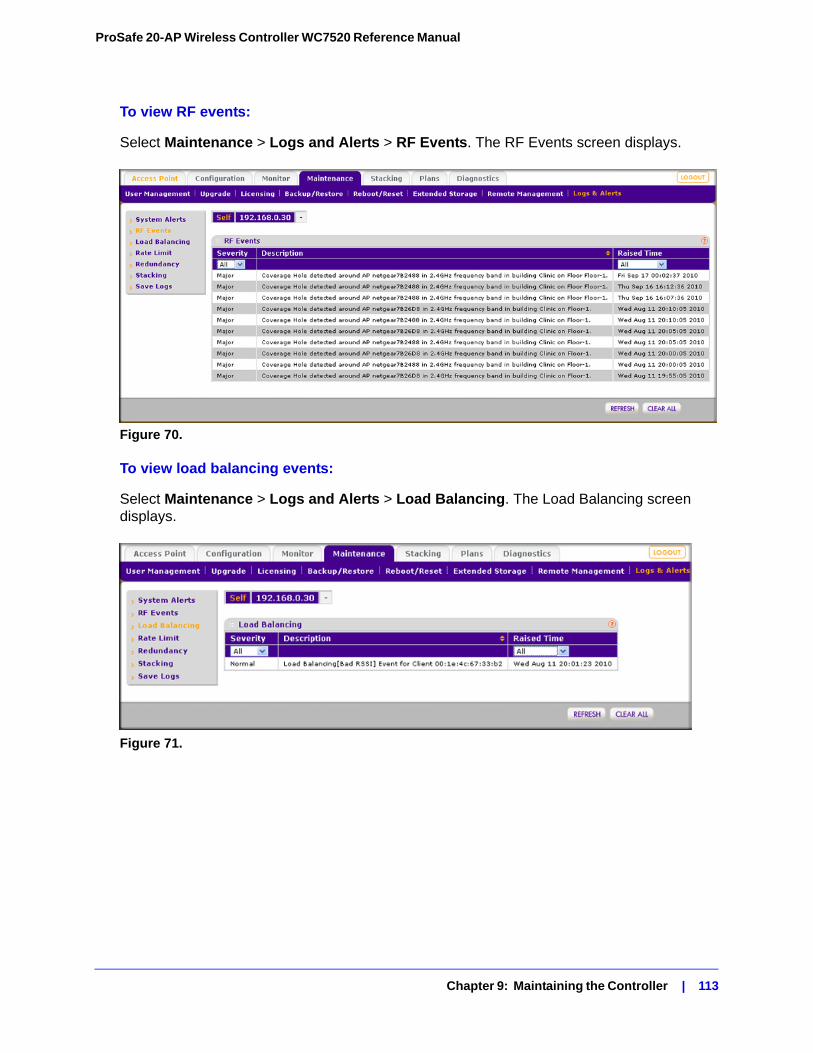
ProSafe 20-AP Wireless Controller WC7520 Reference Manual
To view RF events:
Select Maintenance > Logs and Alerts > RF Events. The RF Events screen displays.
Figure 70.
To view load balancing events:
Select Maintenance > Logs and Alerts > Load Balancing. The Load Balancing screen displays.
Figure 71.
Chapter 9: Maintaining the Controller | 113
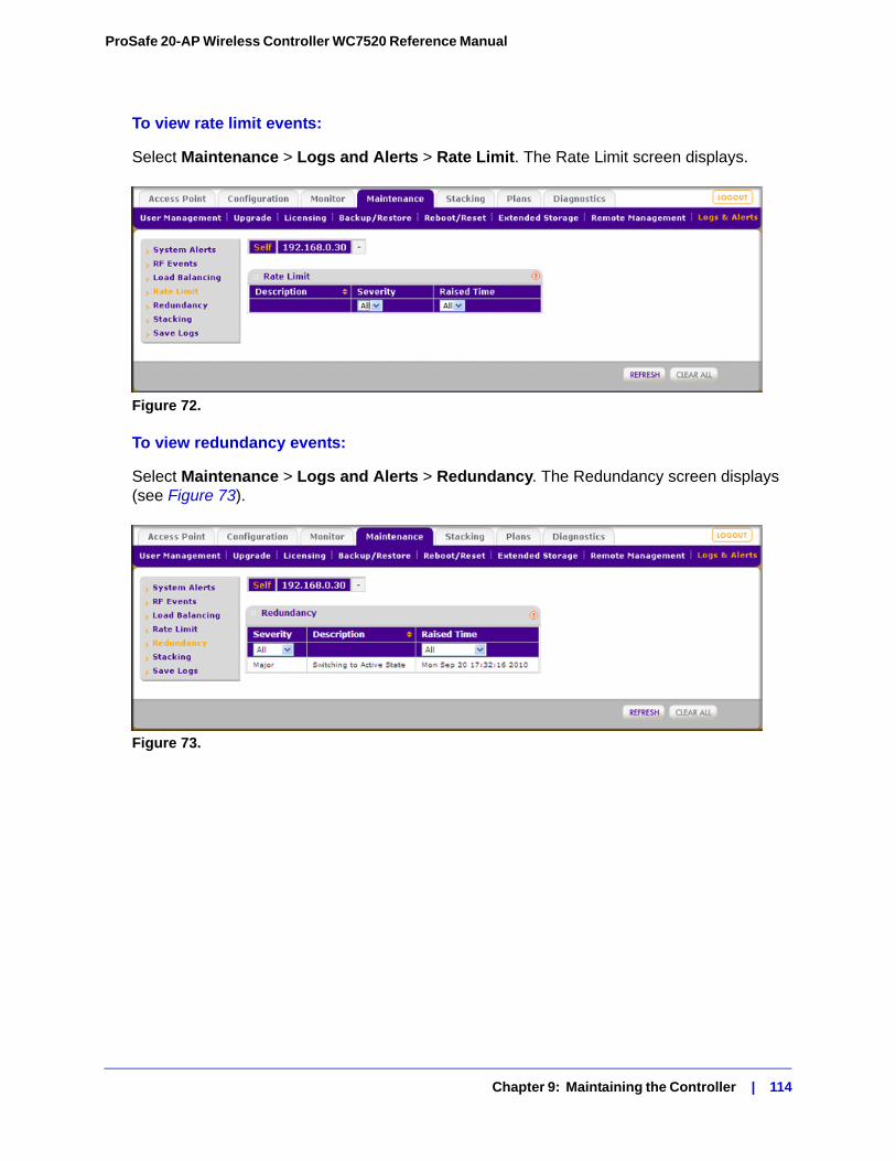
ProSafe 20-AP Wireless Controller WC7520 Reference Manual
To view rate limit events:
Select Maintenance > Logs and Alerts > Rate Limit. The Rate Limit screen displays.
Figure 72.
To view redundancy events:
Select Maintenance > Logs and Alerts > Redundancy. The Redundancy screen displays (see Figure 73).
Figure 73.
Chapter 9: Maintaining the Controller | 114
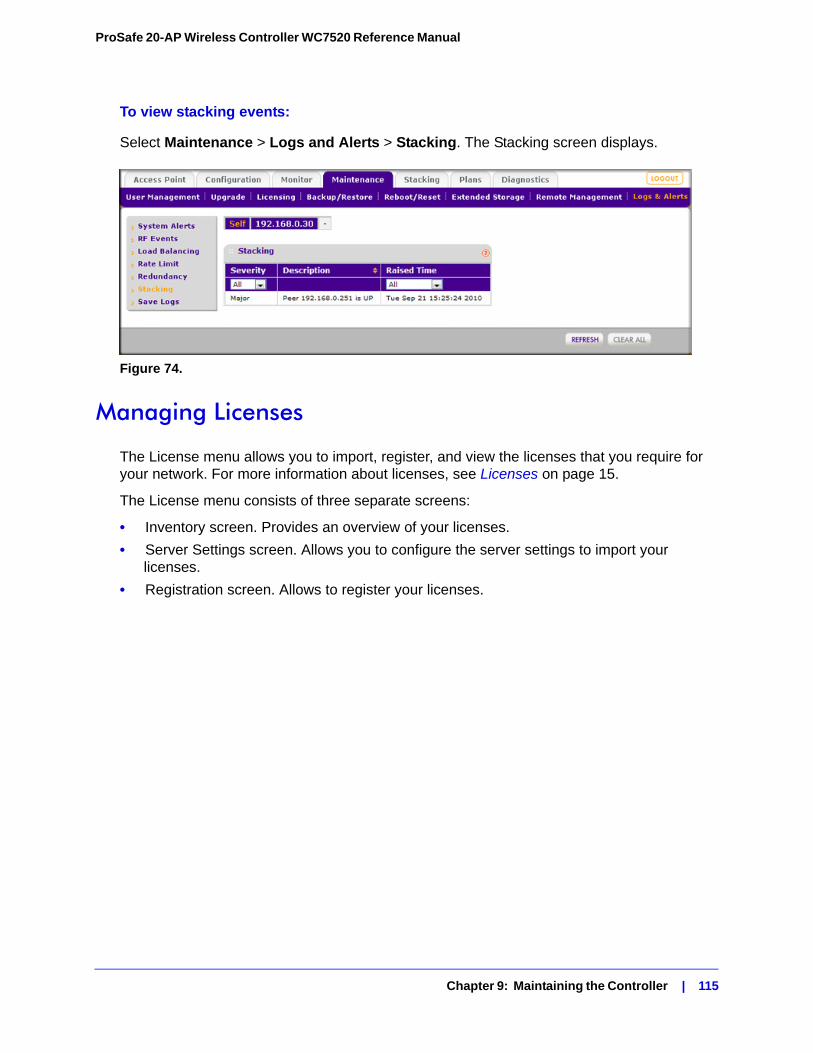
ProSafe 20-AP Wireless Controller WC7520 Reference Manual
To view stacking events:
Select Maintenance > Logs and Alerts > Stacking. The Stacking screen displays.
Figure 74.
Managing Licenses
The License menu allows you to import, register, and view the licenses that you require for your network. For more information about licenses, see Licenses on page 15.
The License menu consists of three separate screens:
• Inventory screen. Provides an overview of your licenses.
• Server Settings screen. Allows you to configure the server settings to import your licenses.
• Registration screen. Allows to register your licenses.
Chapter 9: Maintaining the Controller | 115
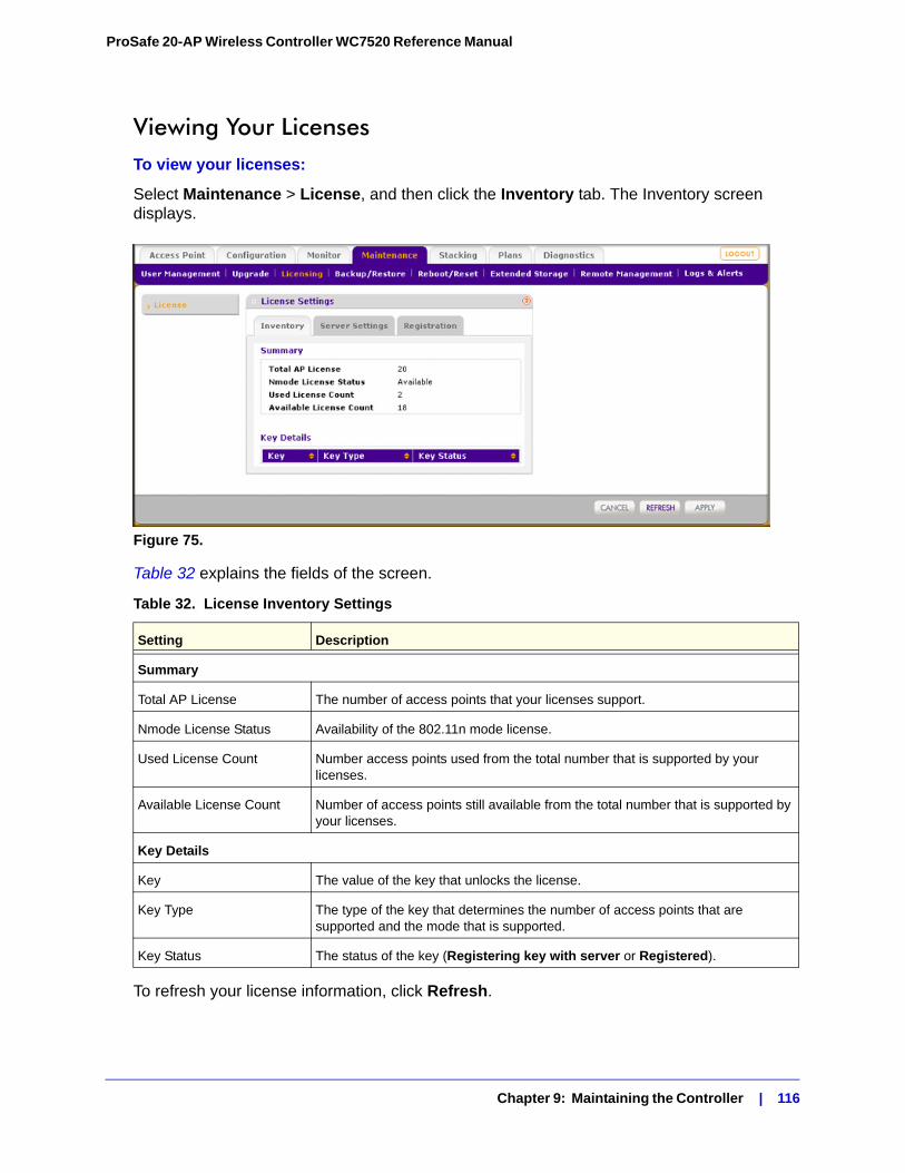
ProSafe 20-AP Wireless Controller WC7520 Reference Manual
Viewing Your LicensesTo view your licenses:
Select Maintenance > License, and then click the Inventory tab. The Inventory screen displays.
Figure 75.
Table 32 explains the fields of the screen.
To refresh your license information, click Refresh.
Table 32. License Inventory Settings
Setting Description
Summary
Total AP License The number of access points that your licenses support.
Nmode License Status Availability of the 802.11n mode license.
Used License Count Number access points used from the total number that is supported by your licenses.
Available License Count Number of access points still available from the total number that is supported by your licenses.
Key Details
Key The value of the key that unlocks the license.
Key Type The type of the key that determines the number of access points that are supported and the mode that is supported.
Key Status The status of the key (Registering key with server or Registered).
Chapter 9: Maintaining the Controller | 116
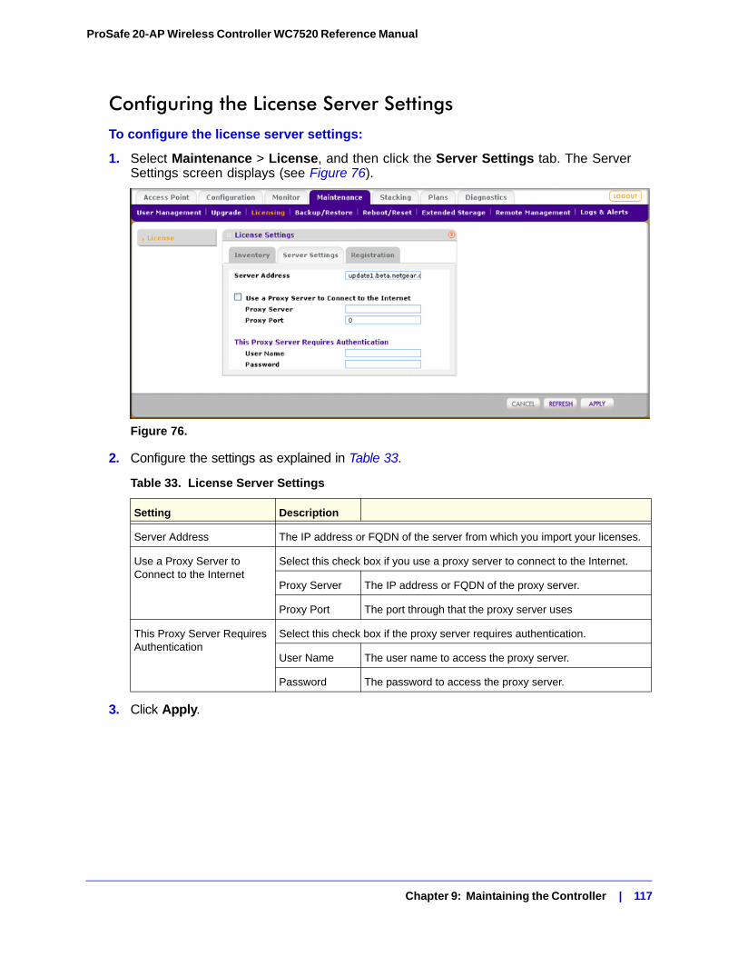
ProSafe 20-AP Wireless Controller WC7520 Reference Manual
Configuring the License Server SettingsTo configure the license server settings:
1. Select Maintenance > License, and then click the Server Settings tab. The Server Settings screen displays (see Figure 76).
Figure 76.
2. Configure the settings as explained in Table 33.
3. Click Apply.
Table 33. License Server Settings
Setting Description
Server Address The IP address or FQDN of the server from which you import your licenses.
Use a Proxy Server to Connect to the Internet
Select this check box if you use a proxy server to connect to the Internet.
Proxy Server The IP address or FQDN of the proxy server.
Proxy Port The port through that the proxy server uses
This Proxy Server Requires Authentication
Select this check box if the proxy server requires authentication.
User Name The user name to access the proxy server.
Password The password to access the proxy server.
Chapter 9: Maintaining the Controller | 117
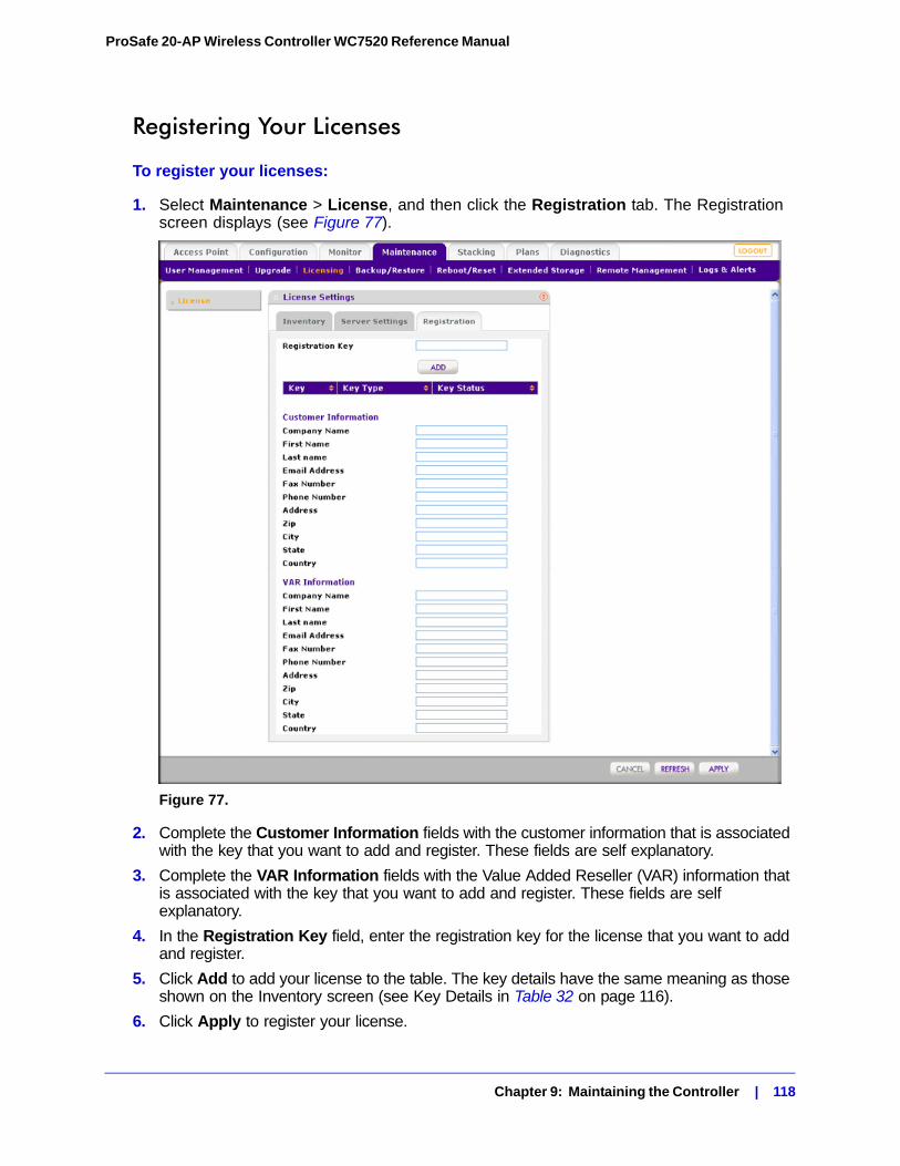
ProSafe 20-AP Wireless Controller WC7520 Reference Manual
Registering Your Licenses
To register your licenses:
1. Select Maintenance > License, and then click the Registration tab. The Registration screen displays (see Figure 77).
Figure 77.
2. Complete the Customer Information fields with the customer information that is associated with the key that you want to add and register. These fields are self explanatory.
3. Complete the VAR Information fields with the Value Added Reseller (VAR) information that is associated with the key that you want to add and register. These fields are self explanatory.
4. In the Registration Key field, enter the registration key for the license that you want to add and register.
5. Click Add to add your license to the table. The key details have the same meaning as those shown on the Inventory screen (see Key Details in Table 32 on page 116).
6. Click Apply to register your license.
Chapter 9: Maintaining the Controller | 118
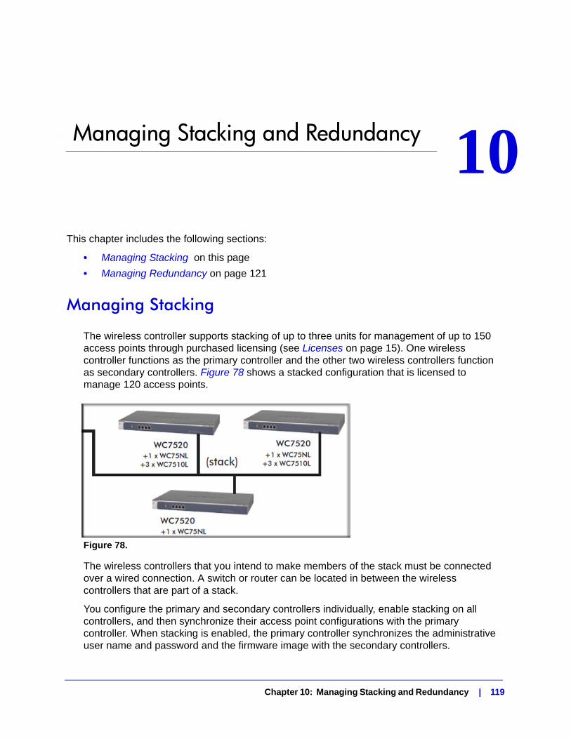
10. Managing Stacking and Redundancy 10
This chapter includes the following sections:• Managing Stacking on this page
• Managing Redundancy on page 121
Managing Stacking
The wireless controller supports stacking of up to three units for management of up to 150 access points through purchased licensing (see Licenses on page 15). One wireless controller functions as the primary controller and the other two wireless controllers function as secondary controllers. Figure 78 shows a stacked configuration that is licensed to manage 120 access points.
Figure 78.
The wireless controllers that you intend to make members of the stack must be connected over a wired connection. A switch or router can be located in between the wireless controllers that are part of a stack.
You configure the primary and secondary controllers individually, enable stacking on all controllers, and then synchronize their access point configurations with the primary controller. When stacking is enabled, the primary controller synchronizes the administrative user name and password and the firmware image with the secondary controllers.
Chapter 10: Managing Stacking and Redundancy | 119
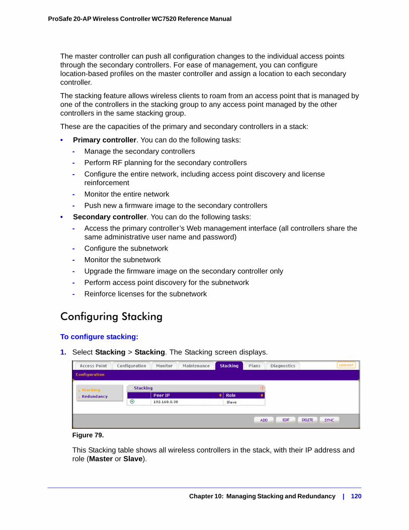
ProSafe 20-AP Wireless Controller WC7520 Reference Manual
The master controller can push all configuration changes to the individual access points through the secondary controllers. For ease of management, you can configure location-based profiles on the master controller and assign a location to each secondary controller.
The stacking feature allows wireless clients to roam from an access point that is managed by one of the controllers in the stacking group to any access point managed by the other controllers in the same stacking group.
These are the capacities of the primary and secondary controllers in a stack:
• Primary controller. You can do the following tasks:
- Manage the secondary controllers
- Perform RF planning for the secondary controllers
- Configure the entire network, including access point discovery and license reinforcement
- Monitor the entire network
- Push new a firmware image to the secondary controllers
• Secondary controller. You can do the following tasks:
- Access the primary controller’s Web management interface (all controllers share the same administrative user name and password)
- Configure the subnetwork
- Monitor the subnetwork
- Upgrade the firmware image on the secondary controller only
- Perform access point discovery for the subnetwork
- Reinforce licenses for the subnetwork
Configuring Stacking
To configure stacking:
1. Select Stacking > Stacking. The Stacking screen displays.
Figure 79.
This Stacking table shows all wireless controllers in the stack, with their IP address and role (Master or Slave).
Chapter 10: Managing Stacking and Redundancy | 120
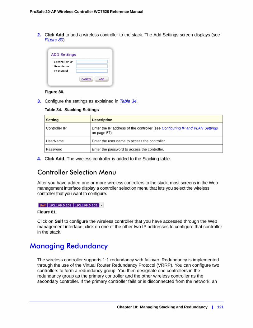
ProSafe 20-AP Wireless Controller WC7520 Reference Manual
2. Click Add to add a wireless controller to the stack. The Add Settings screen displays (see Figure 80).
Figure 80.
3. Configure the settings as explained in Table 34.
4. Click Add. The wireless controller is added to the Stacking table.
Controller Selection MenuAfter you have added one or more wireless controllers to the stack, most screens in the Web management interface display a controller selection menu that lets you select the wireless controller that you want to configure.
Figure 81.
Click on Self to configure the wireless controller that you have accessed through the Web management interface; click on one of the other two IP addresses to configure that controller in the stack.
Managing Redundancy
The wireless controller supports 1:1 redundancy with failover. Redundancy is implemented through the use of the Virtual Router Redundancy Protocol (VRRP). You can configure two controllers to form a redundancy group. You then designate one controllers in the redundancy group as the primary controller and the other wireless controller as the secondary controller. If the primary controller fails or is disconnected from the network, an
Table 34. Stacking Settings
Setting Description
Controller IP Enter the IP address of the controller (see Configuring IP and VLAN Settings on page 57).
UserName Enter the user name to access the controller.
Password Enter the password to access the controller.
Chapter 10: Managing Stacking and Redundancy | 121
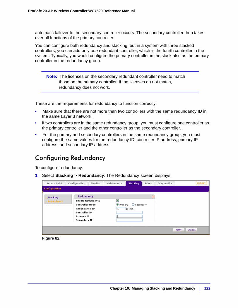
ProSafe 20-AP Wireless Controller WC7520 Reference Manual
automatic failover to the secondary controller occurs. The secondary controller then takes over all functions of the primary controller.
You can configure both redundancy and stacking, but in a system with three stacked controllers, you can add only one redundant controller, which is the fourth controller in the system. Typically, you would configure the primary controller in the stack also as the primary controller in the redundancy group.
Note: The licenses on the secondary redundant controller need to match those on the primary controller. If the licenses do not match, redundancy does not work.
These are the requirements for redundancy to function correctly:
• Make sure that there are not more than two controllers with the same redundancy ID in the same Layer 3 network.
• If two controllers are in the same redundancy group, you must configure one controller as the primary controller and the other controller as the secondary controller.
• For the primary and secondary controllers in the same redundancy group, you must configure the same values for the redundancy ID, controller IP address, primary IP address, and secondary IP address.
Configuring RedundancyTo configure redundancy:
1. Select Stacking > Redundancy. The Redundancy screen displays.
Figure 82.
Chapter 10: Managing Stacking and Redundancy | 122
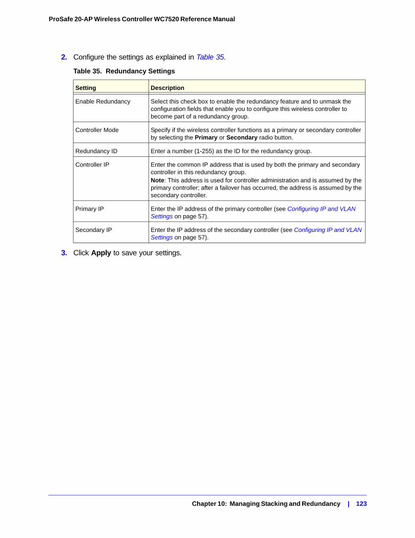
ProSafe 20-AP Wireless Controller WC7520 Reference Manual
2. Configure the settings as explained in Table 35.
3. Click Apply to save your settings.
Table 35. Redundancy Settings
Setting Description
Enable Redundancy Select this check box to enable the redundancy feature and to unmask the configuration fields that enable you to configure this wireless controller to become part of a redundancy group.
Controller Mode Specify if the wireless controller functions as a primary or secondary controller by selecting the Primary or Secondary radio button.
Redundancy ID Enter a number (1-255) as the ID for the redundancy group.
Controller IP Enter the common IP address that is used by both the primary and secondary controller in this redundancy group.Note: This address is used for controller administration and is assumed by the primary controller; after a failover has occurred, the address is assumed by the secondary controller.
Primary IP Enter the IP address of the primary controller (see Configuring IP and VLAN Settings on page 57).
Secondary IP Enter the IP address of the secondary controller (see Configuring IP and VLAN Settings on page 57).
Chapter 10: Managing Stacking and Redundancy | 123
11. Monitoring the Wireless Network and Components 11
This chapter includes the following sections:• Monitoring the Network on page 124
• Monitoring the Wireless Controller on page 134
• Monitoring the SSIDs on page 141
• Monitoring the Clients on page 142
The monitoring screens display read-only status information of the network and its various components.
Monitoring the Network
Note: The Network navigation menu tab displays under the Monitor main navigation tab only when you have configured stacking. If you have not configured stacking, go to Monitoring the Wireless Controller on page 134.
To monitor the network:
1. Select Monitor > Network.
2. Select one of the following submenu links to display a network monitoring screen:
• Summary. See Viewing the Network Summary Screen on page 125.
• Usage. See Viewing Network Usage on page 126.
• Controller. See Viewing Wireless Controllers in the Network on page 127.
• Access Points. See Viewing Managed Access Points in the Network on page 127.
• Clients. See Viewing Clients in the Network on page 131.
• Profiles. See Viewing Security Profiles in the Network on page 133.
Chapter 11: Monitoring the Wireless Network and Components | 124
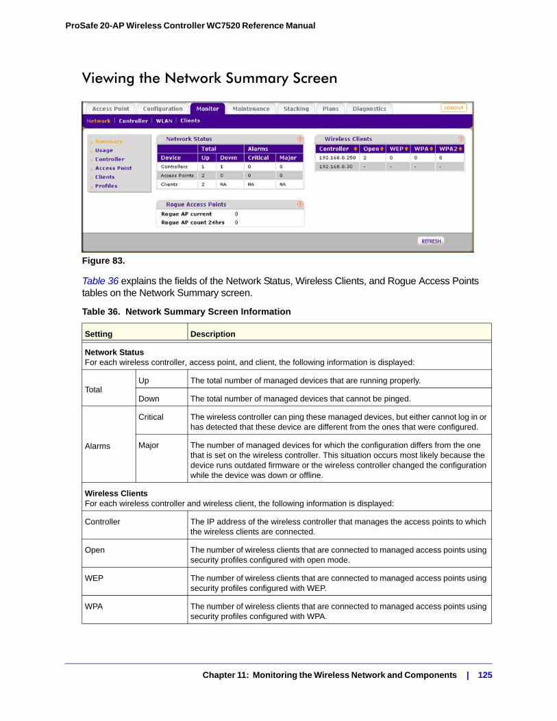
ProSafe 20-AP Wireless Controller WC7520 Reference Manual
Viewing the Network Summary Screen
Figure 83.
Table 36 explains the fields of the Network Status, Wireless Clients, and Rogue Access Points tables on the Network Summary screen.
Table 36. Network Summary Screen Information
Setting Description
Network StatusFor each wireless controller, access point, and client, the following information is displayed:
TotalUp The total number of managed devices that are running properly.
Down The total number of managed devices that cannot be pinged.
Alarms
Critical The wireless controller can ping these managed devices, but either cannot log in or has detected that these device are different from the ones that were configured.
Major The number of managed devices for which the configuration differs from the one that is set on the wireless controller. This situation occurs most likely because the device runs outdated firmware or the wireless controller changed the configuration while the device was down or offline.
Wireless ClientsFor each wireless controller and wireless client, the following information is displayed:
Controller The IP address of the wireless controller that manages the access points to which the wireless clients are connected.
Open The number of wireless clients that are connected to managed access points using security profiles configured with open mode.
WEP The number of wireless clients that are connected to managed access points using security profiles configured with WEP.
WPA The number of wireless clients that are connected to managed access points using security profiles configured with WPA.
Chapter 11: Monitoring the Wireless Network and Components | 125
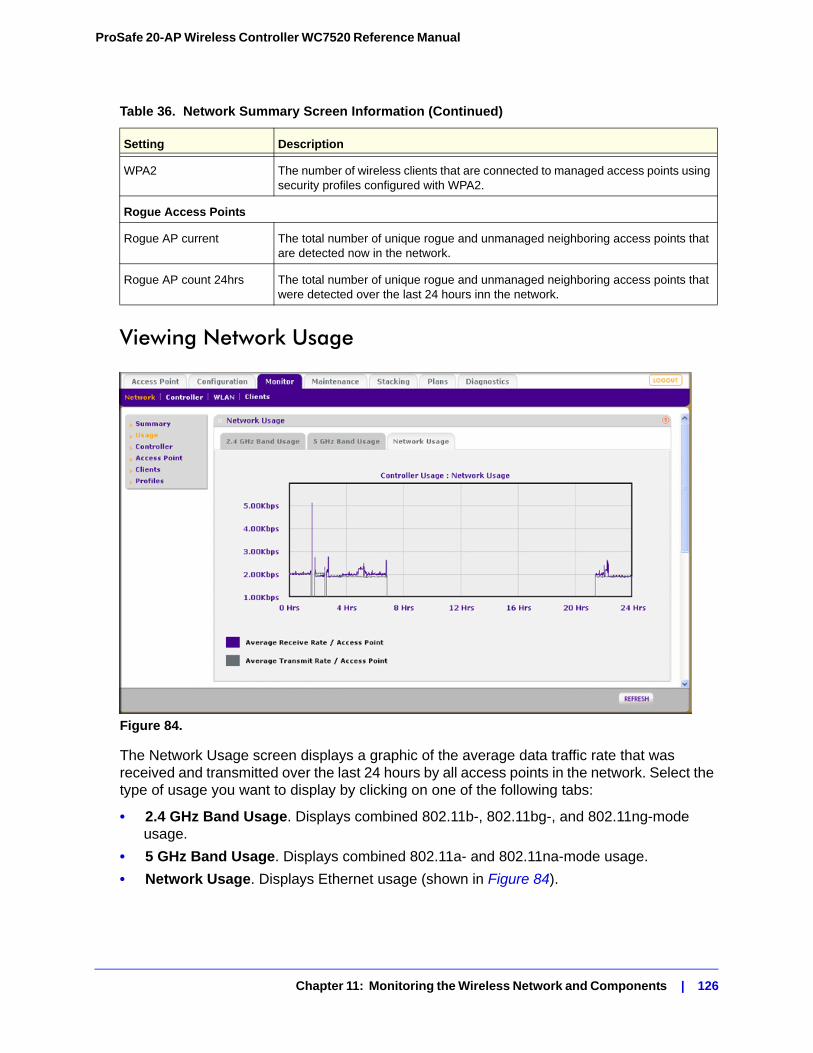
ProSafe 20-AP Wireless Controller WC7520 Reference Manual
Viewing Network Usage
Figure 84.
The Network Usage screen displays a graphic of the average data traffic rate that was received and transmitted over the last 24 hours by all access points in the network. Select the type of usage you want to display by clicking on one of the following tabs:
• 2.4 GHz Band Usage. Displays combined 802.11b-, 802.11bg-, and 802.11ng-mode usage.
• 5 GHz Band Usage. Displays combined 802.11a- and 802.11na-mode usage.
• Network Usage. Displays Ethernet usage (shown in Figure 84).
WPA2 The number of wireless clients that are connected to managed access points using security profiles configured with WPA2.
Rogue Access Points
Rogue AP current The total number of unique rogue and unmanaged neighboring access points that are detected now in the network.
Rogue AP count 24hrs The total number of unique rogue and unmanaged neighboring access points that were detected over the last 24 hours inn the network.
Table 36. Network Summary Screen Information (Continued)
Setting Description
Chapter 11: Monitoring the Wireless Network and Components | 126
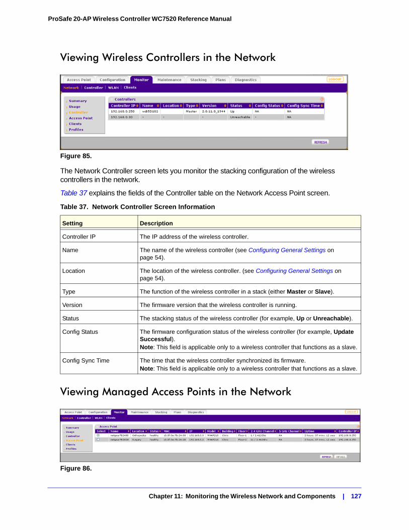
ProSafe 20-AP Wireless Controller WC7520 Reference Manual
Viewing Wireless Controllers in the Network
Figure 85.
The Network Controller screen lets you monitor the stacking configuration of the wireless controllers in the network.
Table 37 explains the fields of the Controller table on the Network Access Point screen.
Viewing Managed Access Points in the Network
Figure 86.
Table 37. Network Controller Screen Information
Setting Description
Controller IP The IP address of the wireless controller.
Name The name of the wireless controller (see Configuring General Settings on page 54).
Location The location of the wireless controller. (see Configuring General Settings on page 54).
Type The function of the wireless controller in a stack (either Master or Slave).
Version The firmware version that the wireless controller is running.
Status The stacking status of the wireless controller (for example, Up or Unreachable).
Config Status The firmware configuration status of the wireless controller (for example, Update Successful).Note: This field is applicable only to a wireless controller that functions as a slave.
Config Sync Time The time that the wireless controller synchronized its firmware.Note: This field is applicable only to a wireless controller that functions as a slave.
Chapter 11: Monitoring the Wireless Network and Components | 127
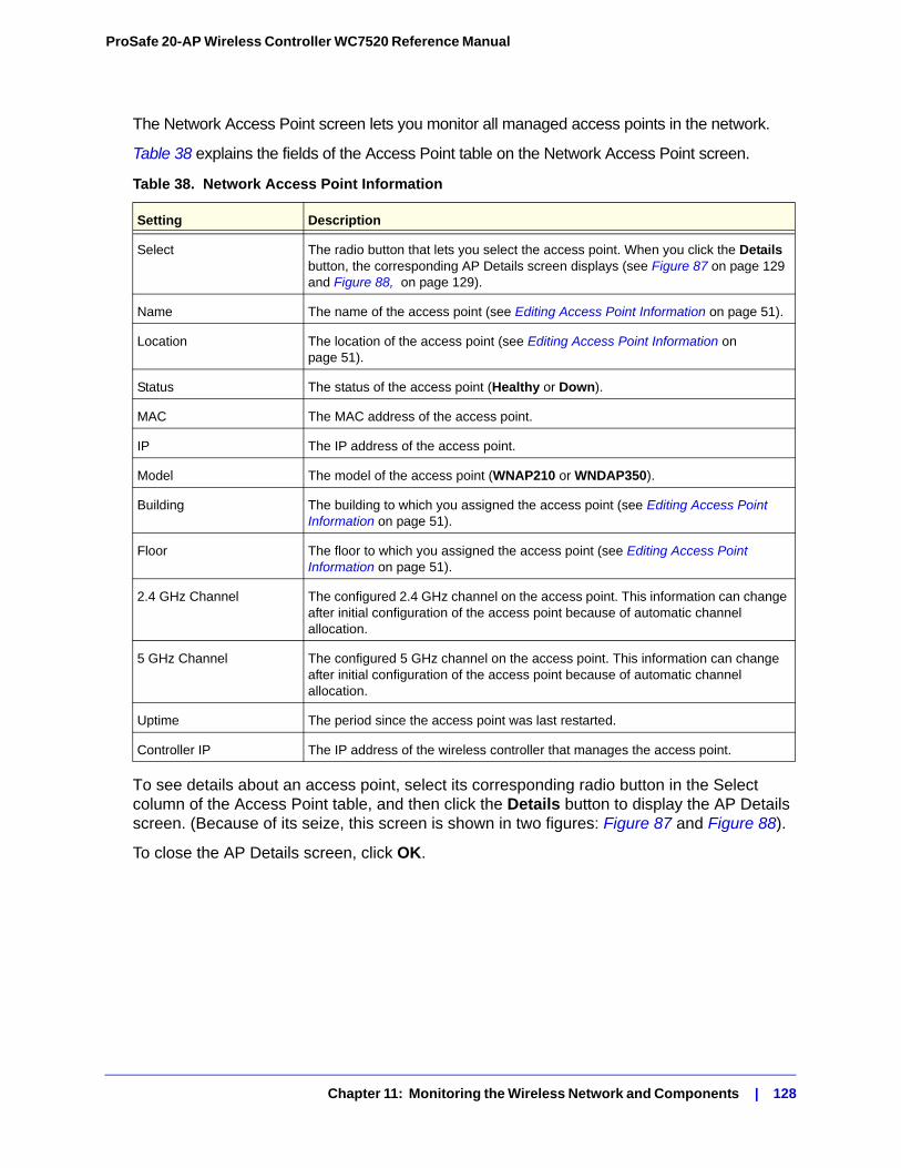
ProSafe 20-AP Wireless Controller WC7520 Reference Manual
The Network Access Point screen lets you monitor all managed access points in the network.
Table 38 explains the fields of the Access Point table on the Network Access Point screen.
To see details about an access point, select its corresponding radio button in the Select column of the Access Point table, and then click the Details button to display the AP Details screen. (Because of its seize, this screen is shown in two figures: Figure 87 and Figure 88).
To close the AP Details screen, click OK.
Table 38. Network Access Point Information
Setting Description
Select The radio button that lets you select the access point. When you click the Details button, the corresponding AP Details screen displays (see Figure 87 on page 129 and Figure 88, on page 129).
Name The name of the access point (see Editing Access Point Information on page 51).
Location The location of the access point (see Editing Access Point Information on page 51).
Status The status of the access point (Healthy or Down).
MAC The MAC address of the access point.
IP The IP address of the access point.
Model The model of the access point (WNAP210 or WNDAP350).
Building The building to which you assigned the access point (see Editing Access Point Information on page 51).
Floor The floor to which you assigned the access point (see Editing Access Point Information on page 51).
2.4 GHz Channel The configured 2.4 GHz channel on the access point. This information can change after initial configuration of the access point because of automatic channel allocation.
5 GHz Channel The configured 5 GHz channel on the access point. This information can change after initial configuration of the access point because of automatic channel allocation.
Uptime The period since the access point was last restarted.
Controller IP The IP address of the wireless controller that manages the access point.
Chapter 11: Monitoring the Wireless Network and Components | 128
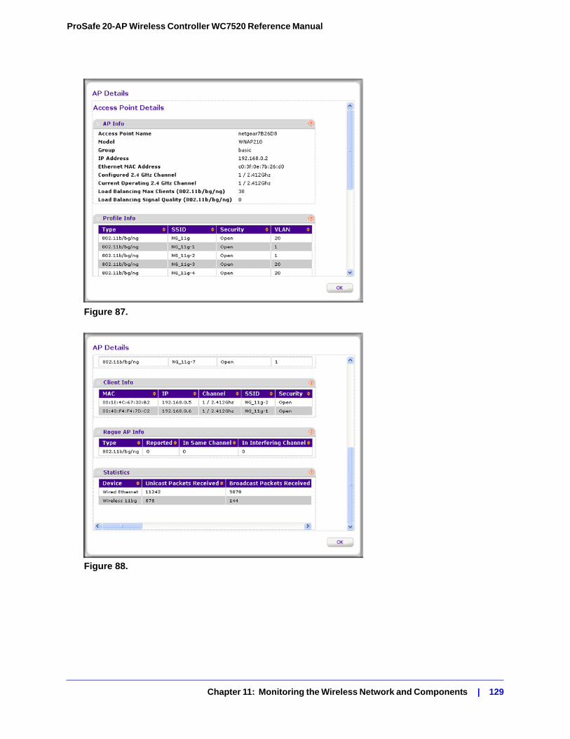
ProSafe 20-AP Wireless Controller WC7520 Reference Manual
Figure 87.
Figure 88.
Chapter 11: Monitoring the Wireless Network and Components | 129
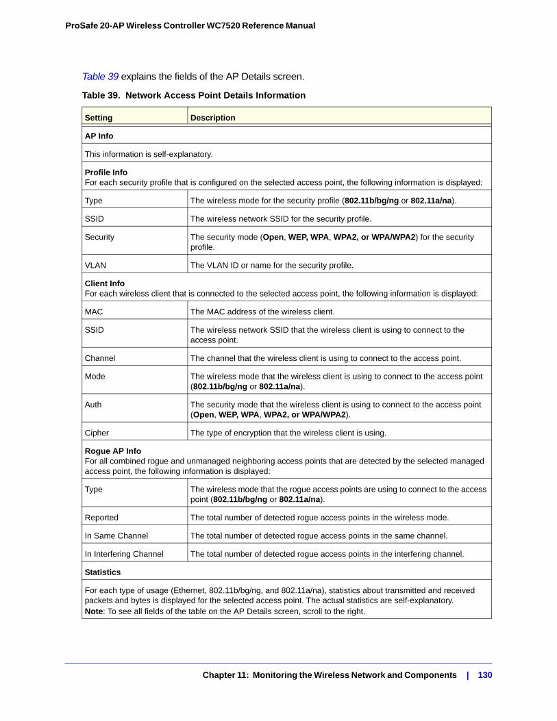
ProSafe 20-AP Wireless Controller WC7520 Reference Manual
Table 39 explains the fields of the AP Details screen.
Table 39. Network Access Point Details Information
Setting Description
AP Info
This information is self-explanatory.
Profile InfoFor each security profile that is configured on the selected access point, the following information is displayed:
Type The wireless mode for the security profile (802.11b/bg/ng or 802.11a/na).
SSID The wireless network SSID for the security profile.
Security The security mode (Open, WEP, WPA, WPA2, or WPA/WPA2) for the security profile.
VLAN The VLAN ID or name for the security profile.
Client InfoFor each wireless client that is connected to the selected access point, the following information is displayed:
MAC The MAC address of the wireless client.
SSID The wireless network SSID that the wireless client is using to connect to the access point.
Channel The channel that the wireless client is using to connect to the access point.
Mode The wireless mode that the wireless client is using to connect to the access point (802.11b/bg/ng or 802.11a/na).
Auth The security mode that the wireless client is using to connect to the access point (Open, WEP, WPA, WPA2, or WPA/WPA2).
Cipher The type of encryption that the wireless client is using.
Rogue AP InfoFor all combined rogue and unmanaged neighboring access points that are detected by the selected managed access point, the following information is displayed:
Type The wireless mode that the rogue access points are using to connect to the access point (802.11b/bg/ng or 802.11a/na).
Reported The total number of detected rogue access points in the wireless mode.
In Same Channel The total number of detected rogue access points in the same channel.
In Interfering Channel The total number of detected rogue access points in the interfering channel.
Statistics
For each type of usage (Ethernet, 802.11b/bg/ng, and 802.11a/na), statistics about transmitted and received packets and bytes is displayed for the selected access point. The actual statistics are self-explanatory.Note: To see all fields of the table on the AP Details screen, scroll to the right.
Chapter 11: Monitoring the Wireless Network and Components | 130
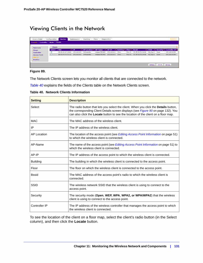
ProSafe 20-AP Wireless Controller WC7520 Reference Manual
Viewing Clients in the Network
Figure 89.
The Network Clients screen lets you monitor all clients that are connected to the network.
Table 40 explains the fields of the Clients table on the Network Clients screen.
To see the location of the client on a floor map, select the client’s radio button (in the Select column), and then click the Locate button.
Table 40. Network Clients Information
Setting Description
Select The radio button that lets you select the client. When you click the Details button, the corresponding Client Details screen displays (see Figure 90 on page 132). You can also click the Locate button to see the location of the client on a floor map.
MAC The MAC address of the wireless client.
IP The IP address of the wireless client.
AP Location The location of the access point (see Editing Access Point Information on page 51) to which the wireless client is connected.
AP-Name The name of the access point (see Editing Access Point Information on page 51) to which the wireless client is connected.
AP-IP The IP address of the access point to which the wireless client is connected.
Building The building in which the wireless client is connected to the access point.
Floor The floor on which the wireless client is connected to the access point.
Bssid The MAC address of the access point’s radio to which the wireless client is connected.
SSID The wireless network SSID that the wireless client is using to connect to the access point.
Security The security mode (Open, WEP, WPA, WPA2, or WPA/WPA2) that the wireless client is using to connect to the access point.
Controller IP The IP address of the wireless controller that manages the access point to which the wireless client is connected.
Chapter 11: Monitoring the Wireless Network and Components | 131
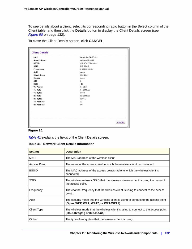
ProSafe 20-AP Wireless Controller WC7520 Reference Manual
To see details about a client, select its corresponding radio button in the Select column of the Client table, and then click the Details button to display the Client Details screen (see Figure 90 on page 132).
To close the Client Details screen, click CANCEL.
Figure 90.
Table 41 explains the fields of the Client Details screen.
Table 41. Network Client Details Information
Setting Description
MAC The MAC address of the wireless client.
Access Point The name of the access point to which the wireless client is connected.
BSSID The MAC address of the access point’s radio to which the wireless client is connected.
SSID The wireless network SSID that the wireless wireless client is using to connect to the access point.
Frequency The channel frequency that the wireless client is using to connect to the access point.
Auth The security mode that the wireless client is using to connect to the access point (Open, WEP, WPA, WPA2, or WPA/WPA2).
Client Type The wireless mode that the wireless client is using to connect to the access point (802.11b/bg/ng or 802.11a/na).
Cipher The type of encryption that the wireless client is using.
Chapter 11: Monitoring the Wireless Network and Components | 132
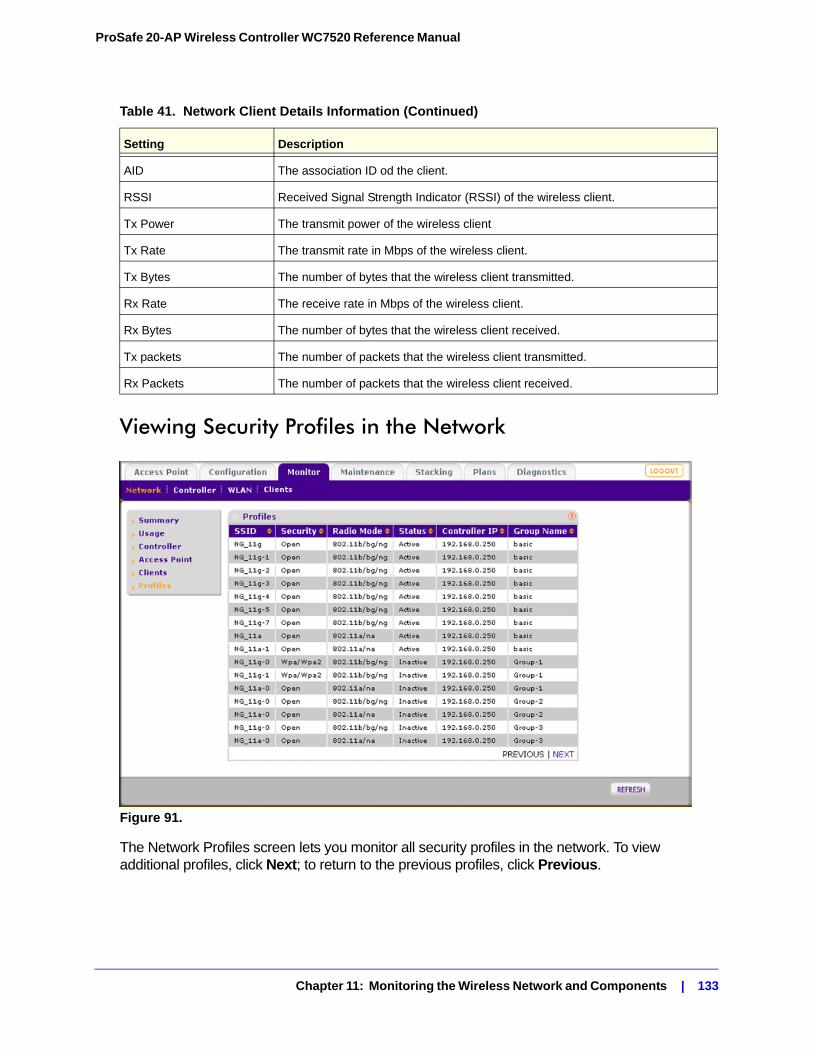
ProSafe 20-AP Wireless Controller WC7520 Reference Manual
Viewing Security Profiles in the Network
Figure 91.
The Network Profiles screen lets you monitor all security profiles in the network. To view additional profiles, click Next; to return to the previous profiles, click Previous.
AID The association ID od the client.
RSSI Received Signal Strength Indicator (RSSI) of the wireless client.
Tx Power The transmit power of the wireless client
Tx Rate The transmit rate in Mbps of the wireless client.
Tx Bytes The number of bytes that the wireless client transmitted.
Rx Rate The receive rate in Mbps of the wireless client.
Rx Bytes The number of bytes that the wireless client received.
Tx packets The number of packets that the wireless client transmitted.
Rx Packets The number of packets that the wireless client received.
Table 41. Network Client Details Information (Continued)
Setting Description
Chapter 11: Monitoring the Wireless Network and Components | 133
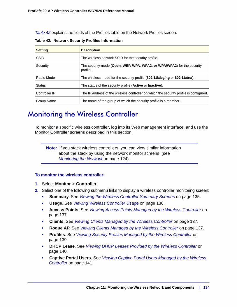
ProSafe 20-AP Wireless Controller WC7520 Reference Manual
Table 42 explains the fields of the Profiles table on the Network Profiles screen.
Monitoring the Wireless Controller
To monitor a specific wireless controller, log into its Web management interface, and use the Monitor Controller screens described in this section.
Note: If you stack wireless controllers, you can view similar information about the stack by using the network monitor screens (see Monitoring the Network on page 124).
To monitor the wireless controller:
1. Select Monitor > Controller.
2. Select one of the following submenu links to display a wireless controller monitoring screen:
• Summary. See Viewing the Wireless Controller Summary Screens on page 135.
• Usage. See Viewing Wireless Controller Usage on page 136.
• Access Points. See Viewing Access Points Managed by the Wireless Controller on page 137.
• Clients. See Viewing Clients Managed by the Wireless Controller on page 137.
• Rogue AP. See Viewing Clients Managed by the Wireless Controller on page 137.
• Profiles. See Viewing Security Profiles Managed by the Wireless Controller on page 139.
• DHCP Lease. See Viewing DHCP Leases Provided by the Wireless Controller on page 140.
• Captive Portal Users. See Viewing Captive Portal Users Managed by the Wireless Controller on page 141.
Table 42. Network Security Profiles Information
Setting Description
SSID The wireless network SSID for the security profile.
Security The security mode (Open, WEP, WPA, WPA2, or WPA/WPA2) for the security profile.
Radio Mode The wireless mode for the security profile (802.11b/bg/ng or 802.11a/na).
Status The status of the security profile (Active or Inactive).
Controller IP The IP address of the wireless controller on which the security profile is configured.
Group Name The name of the group of which the security profile is a member.
Chapter 11: Monitoring the Wireless Network and Components | 134
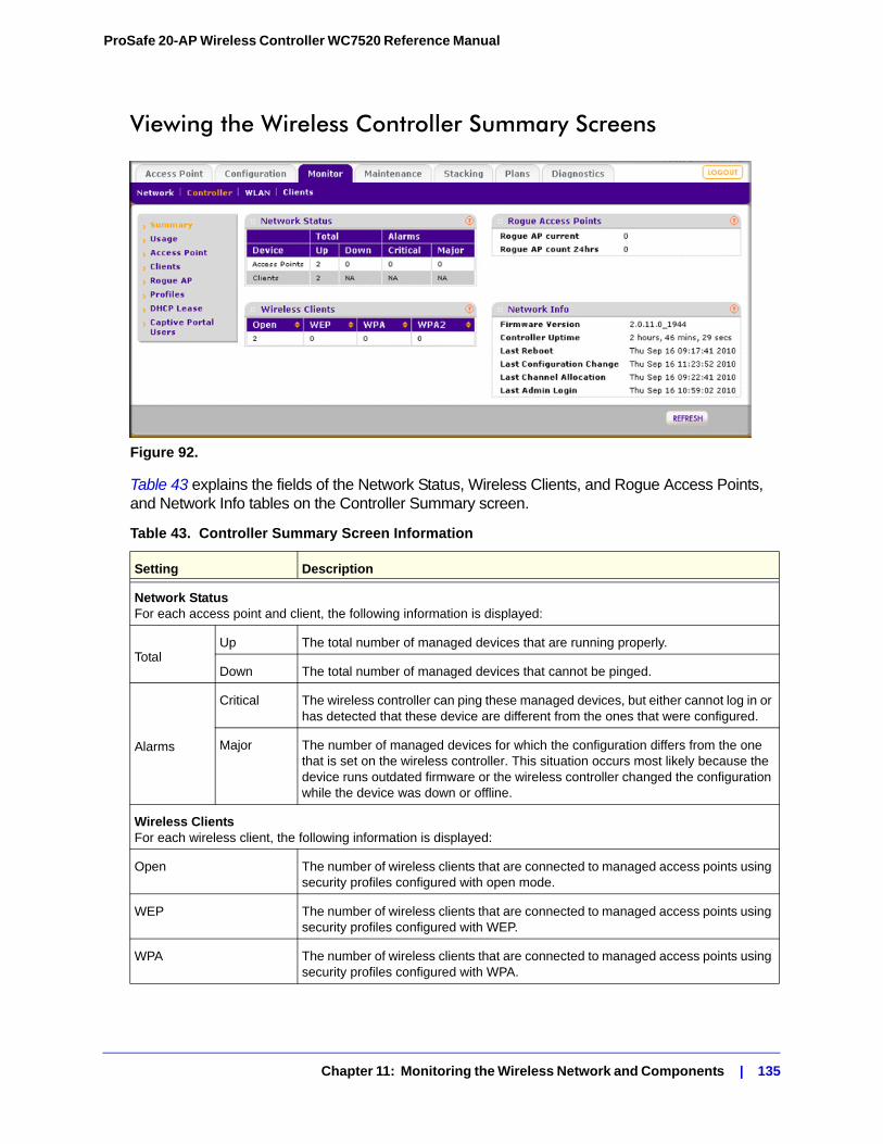
ProSafe 20-AP Wireless Controller WC7520 Reference Manual
Viewing the Wireless Controller Summary Screens
Figure 92.
Table 43 explains the fields of the Network Status, Wireless Clients, and Rogue Access Points, and Network Info tables on the Controller Summary screen.
Table 43. Controller Summary Screen Information
Setting Description
Network StatusFor each access point and client, the following information is displayed:
TotalUp The total number of managed devices that are running properly.
Down The total number of managed devices that cannot be pinged.
Alarms
Critical The wireless controller can ping these managed devices, but either cannot log in or has detected that these device are different from the ones that were configured.
Major The number of managed devices for which the configuration differs from the one that is set on the wireless controller. This situation occurs most likely because the device runs outdated firmware or the wireless controller changed the configuration while the device was down or offline.
Wireless ClientsFor each wireless client, the following information is displayed:
Open The number of wireless clients that are connected to managed access points using security profiles configured with open mode.
WEP The number of wireless clients that are connected to managed access points using security profiles configured with WEP.
WPA The number of wireless clients that are connected to managed access points using security profiles configured with WPA.
Chapter 11: Monitoring the Wireless Network and Components | 135
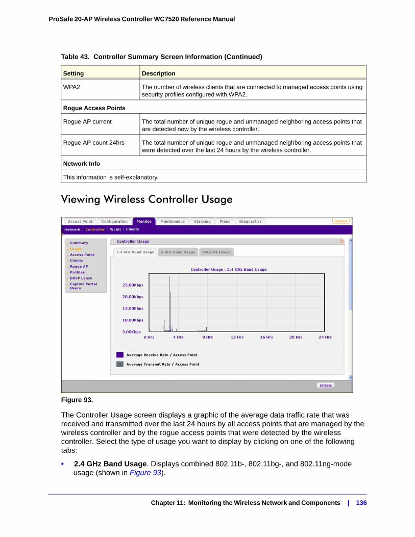
ProSafe 20-AP Wireless Controller WC7520 Reference Manual
Viewing Wireless Controller Usage
Figure 93.
The Controller Usage screen displays a graphic of the average data traffic rate that was received and transmitted over the last 24 hours by all access points that are managed by the wireless controller and by the rogue access points that were detected by the wireless controller. Select the type of usage you want to display by clicking on one of the following tabs:
• 2.4 GHz Band Usage. Displays combined 802.11b-, 802.11bg-, and 802.11ng-mode usage (shown in Figure 93).
WPA2 The number of wireless clients that are connected to managed access points using security profiles configured with WPA2.
Rogue Access Points
Rogue AP current The total number of unique rogue and unmanaged neighboring access points that are detected now by the wireless controller.
Rogue AP count 24hrs The total number of unique rogue and unmanaged neighboring access points that were detected over the last 24 hours by the wireless controller.
Network Info
This information is self-explanatory.
Table 43. Controller Summary Screen Information (Continued)
Setting Description
Chapter 11: Monitoring the Wireless Network and Components | 136
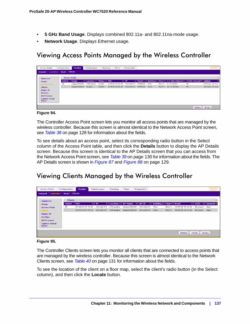
ProSafe 20-AP Wireless Controller WC7520 Reference Manual
• 5 GHz Band Usage. Displays combined 802.11a- and 802.11na-mode usage.
• Network Usage. Displays Ethernet usage.
Viewing Access Points Managed by the Wireless Controller
Figure 94.
The Controller Access Point screen lets you monitor all access points that are managed by the wireless controller. Because this screen is almost identical to the Network Access Point screen, see Table 38 on page 128 for information about the fields.
To see details about an access point, select its corresponding radio button in the Select column of the Access Point table, and then click the Details button to display the AP Details screen. Because this screen is identical to the AP Details screen that you can access from the Network Access Point screen, see Table 39 on page 130 for information about the fields. The AP Details screen is shown in Figure 87 and Figure 88 on page 129.
Viewing Clients Managed by the Wireless Controller
Figure 95.
The Controller Clients screen lets you monitor all clients that are connected to access points that are managed by the wireless controller. Because this screen is almost identical to the Network Clients screen, see Table 40 on page 131 for information about the fields.
To see the location of the client on a floor map, select the client’s radio button (in the Select column), and then click the Locate button.
Chapter 11: Monitoring the Wireless Network and Components | 137
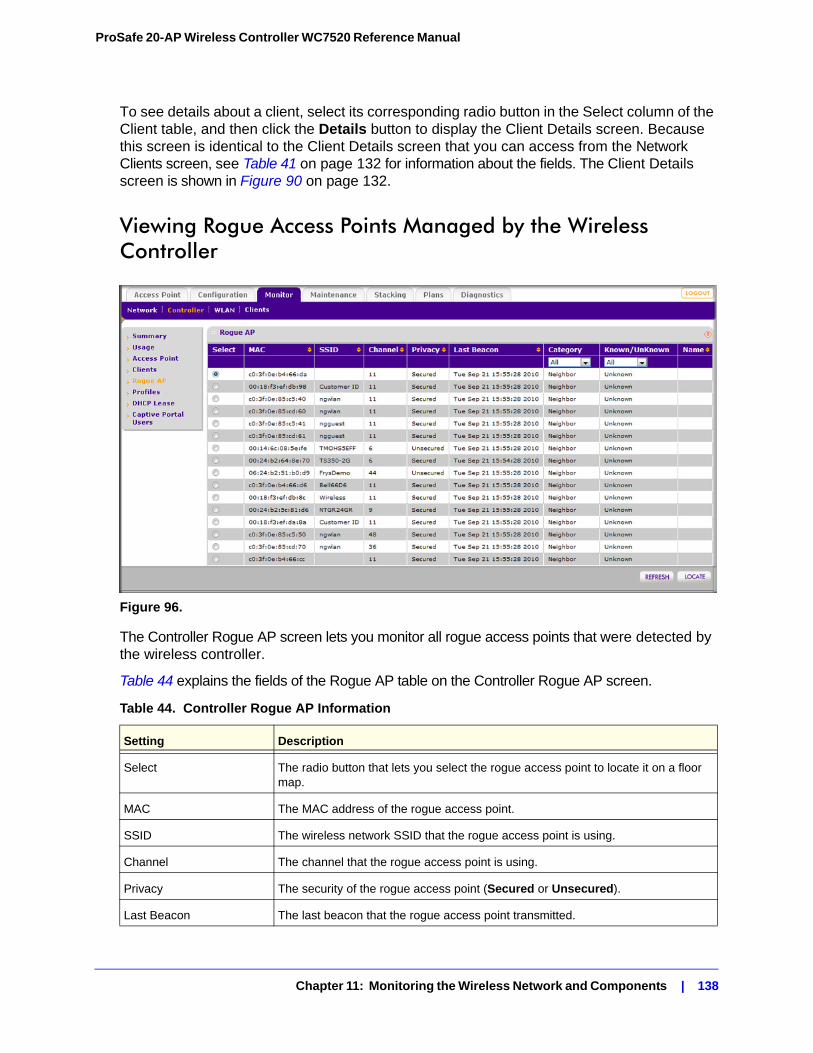
ProSafe 20-AP Wireless Controller WC7520 Reference Manual
To see details about a client, select its corresponding radio button in the Select column of the Client table, and then click the Details button to display the Client Details screen. Because this screen is identical to the Client Details screen that you can access from the Network Clients screen, see Table 41 on page 132 for information about the fields. The Client Details screen is shown in Figure 90 on page 132.
Viewing Rogue Access Points Managed by the Wireless Controller
Figure 96.
The Controller Rogue AP screen lets you monitor all rogue access points that were detected by the wireless controller.
Table 44 explains the fields of the Rogue AP table on the Controller Rogue AP screen.
Table 44. Controller Rogue AP Information
Setting Description
Select The radio button that lets you select the rogue access point to locate it on a floor map.
MAC The MAC address of the rogue access point.
SSID The wireless network SSID that the rogue access point is using.
Channel The channel that the rogue access point is using.
Privacy The security of the rogue access point (Secured or Unsecured).
Last Beacon The last beacon that the rogue access point transmitted.
Chapter 11: Monitoring the Wireless Network and Components | 138
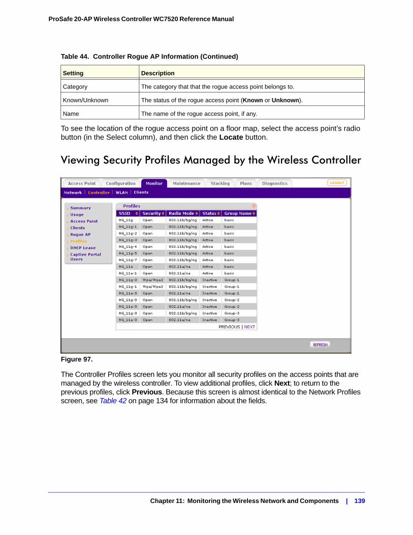
ProSafe 20-AP Wireless Controller WC7520 Reference Manual
To see the location of the rogue access point on a floor map, select the access point’s radio button (in the Select column), and then click the Locate button.
Viewing Security Profiles Managed by the Wireless Controller
Figure 97.
The Controller Profiles screen lets you monitor all security profiles on the access points that are managed by the wireless controller. To view additional profiles, click Next; to return to the previous profiles, click Previous. Because this screen is almost identical to the Network Profiles screen, see Table 42 on page 134 for information about the fields.
Category The category that that the rogue access point belongs to.
Known/Unknown The status of the rogue access point (Known or Unknown).
Name The name of the rogue access point, if any.
Table 44. Controller Rogue AP Information (Continued)
Setting Description
Chapter 11: Monitoring the Wireless Network and Components | 139
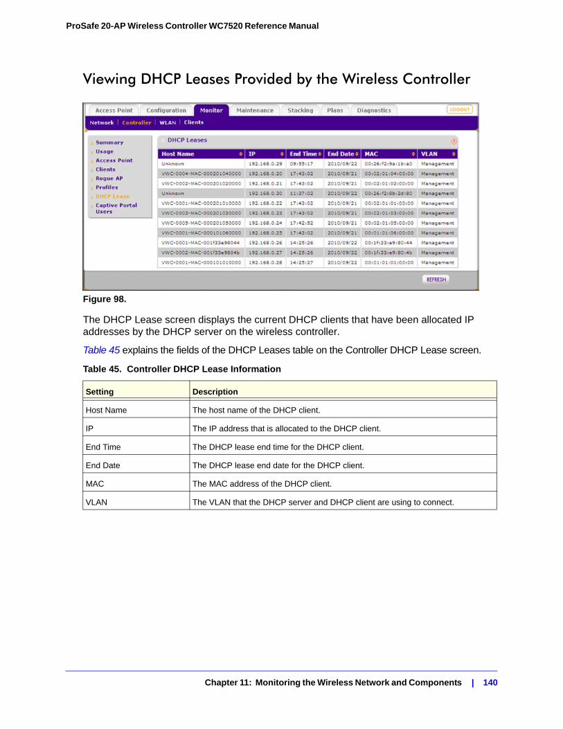
ProSafe 20-AP Wireless Controller WC7520 Reference Manual
Viewing DHCP Leases Provided by the Wireless Controller
Figure 98.
The DHCP Lease screen displays the current DHCP clients that have been allocated IP addresses by the DHCP server on the wireless controller.
Table 45 explains the fields of the DHCP Leases table on the Controller DHCP Lease screen.
Table 45. Controller DHCP Lease Information
Setting Description
Host Name The host name of the DHCP client.
IP The IP address that is allocated to the DHCP client.
End Time The DHCP lease end time for the DHCP client.
End Date The DHCP lease end date for the DHCP client.
MAC The MAC address of the DHCP client.
VLAN The VLAN that the DHCP server and DHCP client are using to connect.
Chapter 11: Monitoring the Wireless Network and Components | 140
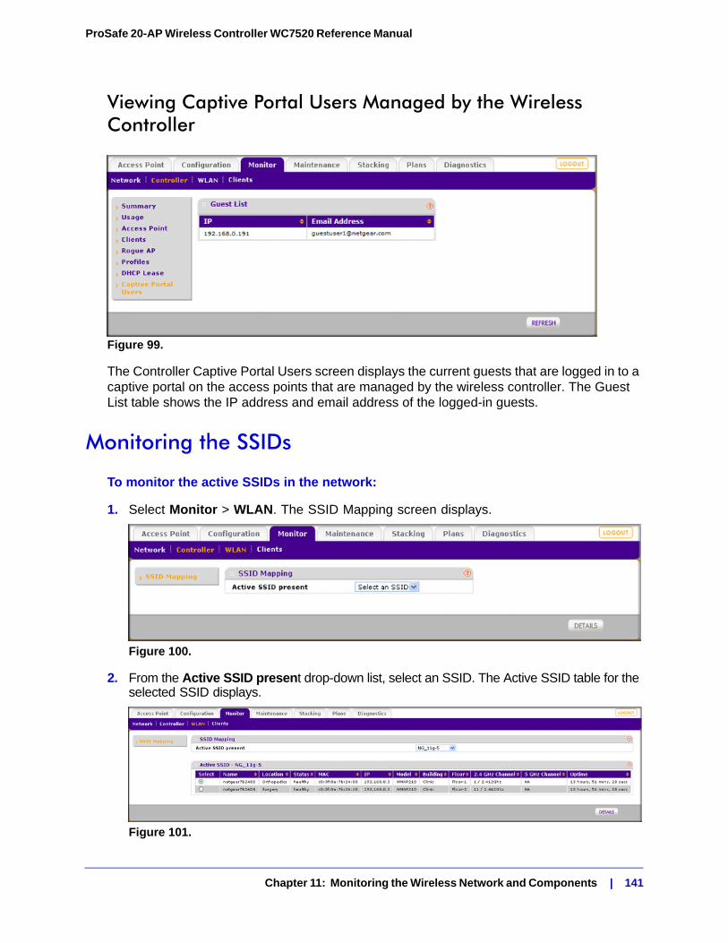
ProSafe 20-AP Wireless Controller WC7520 Reference Manual
Viewing Captive Portal Users Managed by the Wireless Controller
Figure 99.
The Controller Captive Portal Users screen displays the current guests that are logged in to a captive portal on the access points that are managed by the wireless controller. The Guest List table shows the IP address and email address of the logged-in guests.
Monitoring the SSIDs
To monitor the active SSIDs in the network:
1. Select Monitor > WLAN. The SSID Mapping screen displays.
Figure 100.
2. From the Active SSID present drop-down list, select an SSID. The Active SSID table for the selected SSID displays.
Figure 101.
Chapter 11: Monitoring the Wireless Network and Components | 141
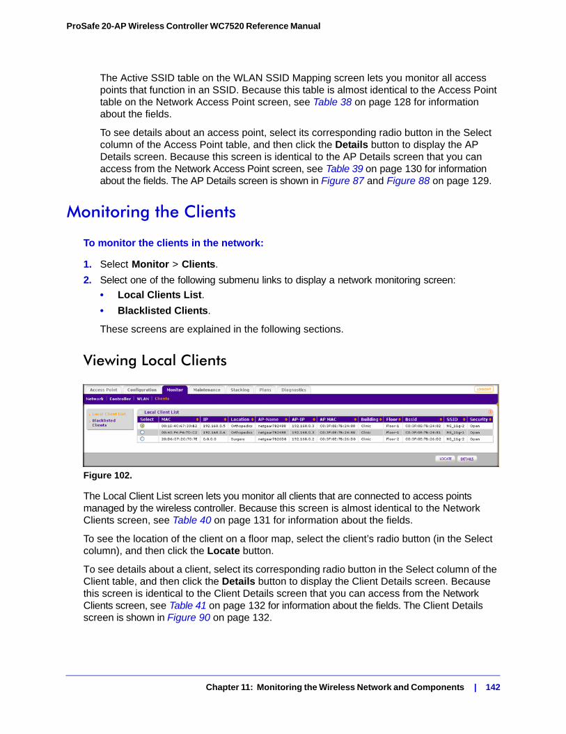
ProSafe 20-AP Wireless Controller WC7520 Reference Manual
The Active SSID table on the WLAN SSID Mapping screen lets you monitor all access points that function in an SSID. Because this table is almost identical to the Access Point table on the Network Access Point screen, see Table 38 on page 128 for information about the fields.
To see details about an access point, select its corresponding radio button in the Select column of the Access Point table, and then click the Details button to display the AP Details screen. Because this screen is identical to the AP Details screen that you can access from the Network Access Point screen, see Table 39 on page 130 for information about the fields. The AP Details screen is shown in Figure 87 and Figure 88 on page 129.
Monitoring the Clients
To monitor the clients in the network:
1. Select Monitor > Clients.
2. Select one of the following submenu links to display a network monitoring screen:
• Local Clients List.
• Blacklisted Clients.
These screens are explained in the following sections.
Viewing Local Clients
Figure 102.
The Local Client List screen lets you monitor all clients that are connected to access points managed by the wireless controller. Because this screen is almost identical to the Network Clients screen, see Table 40 on page 131 for information about the fields.
To see the location of the client on a floor map, select the client’s radio button (in the Select column), and then click the Locate button.
To see details about a client, select its corresponding radio button in the Select column of the Client table, and then click the Details button to display the Client Details screen. Because this screen is identical to the Client Details screen that you can access from the Network Clients screen, see Table 41 on page 132 for information about the fields. The Client Details screen is shown in Figure 90 on page 132.
Chapter 11: Monitoring the Wireless Network and Components | 142
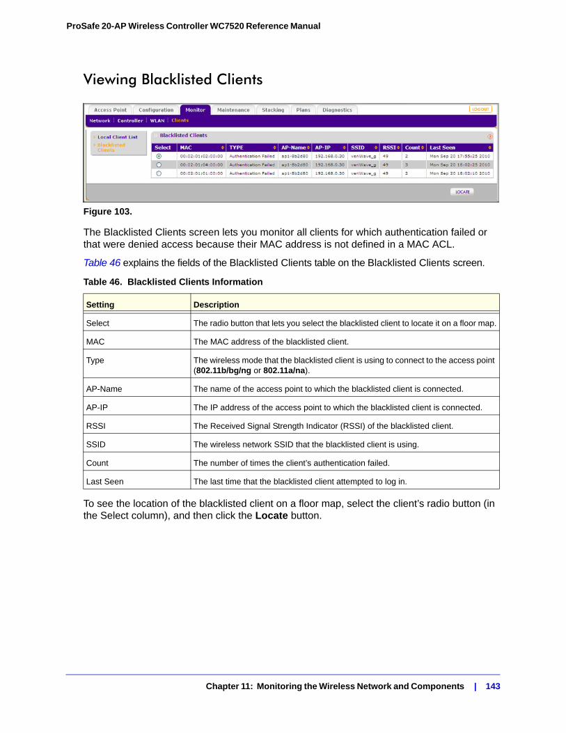
ProSafe 20-AP Wireless Controller WC7520 Reference Manual
Viewing Blacklisted Clients
Figure 103.
The Blacklisted Clients screen lets you monitor all clients for which authentication failed or that were denied access because their MAC address is not defined in a MAC ACL.
Table 46 explains the fields of the Blacklisted Clients table on the Blacklisted Clients screen.
To see the location of the blacklisted client on a floor map, select the client’s radio button (in the Select column), and then click the Locate button.
Table 46. Blacklisted Clients Information
Setting Description
Select The radio button that lets you select the blacklisted client to locate it on a floor map.
MAC The MAC address of the blacklisted client.
Type The wireless mode that the blacklisted client is using to connect to the access point (802.11b/bg/ng or 802.11a/na).
AP-Name The name of the access point to which the blacklisted client is connected.
AP-IP The IP address of the access point to which the blacklisted client is connected.
RSSI The Received Signal Strength Indicator (RSSI) of the blacklisted client.
SSID The wireless network SSID that the blacklisted client is using.
Count The number of times the client’s authentication failed.
Last Seen The last time that the blacklisted client attempted to log in.
Chapter 11: Monitoring the Wireless Network and Components | 143
12. Troubleshooting 12
This chapter includes the following sections:• Troubleshooting Basic Functioning on this page
• Troubleshooting the Web Management Interface on page 145
• When You Enter a URL or IP Address a Time-out Error Occurs on page 147
• Troubleshooting a TCP/IP Network Using the Ping Utility on page 147
• Using the Reset Button to Restore Factory Default Settings on page 148
• Problems with Date and Time on page 148
• Problems With Access Points on page 149
Troubleshooting Basic Functioning
After you turn on power to the wireless controller, the following sequence of events should occur:
1. When power is first applied, verify that the Power LED is on.
2. After approximately 2 minutes, verify that:
a. The Test LED is no longer lit.
b. The left LAN port LEDs are lit for any local ports that are connected.
If a port’s left LED is lit, a link has been established to the connected device. If a port is connected to a 1000 Mbps device, verify that the port’s right LED is green. If the port functions at 100 Mbps, the right LED is amber. If the port functions at 10 Mbps, the right LED is off.
If any of these conditions do not occur, see to the appropriate following section.
Power LED Not OnIf the Power and other LEDs are off when your wireless controller is turned on, make sure that the power cord is correctly connected to your wireless controller and that the power supply adapter is correctly connected to a functioning power outlet.
Chapter 12: Troubleshooting | 144
ProSafe 20-AP Wireless Controller WC7520 Reference Manual
If the error persists, you have a hardware problem and should contact NETGEAR Technical Support.
Test LED Never Turns OffWhen the wireless controller is powered on, the Test LED turns on for approximately 2 minutes and then turns off when the wireless controller has completed its initialization. If the Test LED remains on, there is a fault within the wireless controller.
If the Test LED is still on more than several minutes minute after power up:
• Turn the power off, and then turn it on again to see if the wireless controller recovers.
• Reset the wireless controller’s configuration to factory defaults settings. Doing so sets the wireless controller’s IP address to 192.168.0.250. This procedure is explained in Rebooting or Resetting the Wireless Controller on page 105.
If the error persists, you might have a hardware problem and should contact NETGEAR Technical Support.
LAN Port LEDs Not OnIf the LAN LEDs do not light when the Ethernet connection is made, check the following:
• Make sure that the Ethernet cable connections are secure at the wireless controller and at the hub, switch, or router.
• Make sure that power is turned on to the connected hub, switch, or router.
• Be sure that you are using the correct cables:
Troubleshooting the Web Management Interface
If you are unable to access the wireless controller’s Web Management Interface from a PC on your local network, try to isolate the problem. It is most likely one of the following:
Ethernet CablingCheck the Ethernet connection between the PC and the wireless controller as described in the previous section (see LAN Port LEDs Not On ).
IP Address Configuration• Make sure your PC’s IP address is on the same subnet as the wireless controller. If you
are using the recommended addressing scheme, make sure you PC’s has a static IP address of 192.168.0.210 and a subnet of 255.255.255.0.
Chapter 12: Troubleshooting | 145
ProSafe 20-AP Wireless Controller WC7520 Reference Manual
Note: If your PC’s IP address is shown as 169.254.x.x: Windows and Mac operating systems generate and assign an IP address if the computer cannot reach a DHCP server. These auto-generated addresses are in the range of 169.254.x.x. If your IP address is in this range, check the connection from the PC to the wireless controller and reboot your PC.
• If the wireless controller’s IP address has been changed and you do not know the current IP address, reset the wireless controller’s configuration to factory defaults settings. This sets the wireless controller’s IP address to 192.168.0.250. This procedure is explained in Rebooting or Resetting the Wireless Controller on page 105.
Note: If you do not want to revert to the factory defaults settings and lose your configuration settings, you can reboot the wireless controller and use a sniffer to capture packets sent during the reboot. Look at the ARP packets to locate the wireless controller’s LAN interface address.
Internet Browser• Make sure that you are using the http://address login rather than the https://address login.
• Make sure that your browser has Java, JavaScript, or ActiveX enabled. If you are using Internet Explorer, click Refresh to be sure that the Java applet is loaded.
• Try quitting the browser and launching it again.
• Make sure that you are using the correct login information. The factory defaults login name is admin, and the password is password. Make sure that Caps Lock is off when entering this information.
If the wireless controller does not save changes you have made in the Web configuration interface, check the following:
• When entering configuration settings, be sure to click the Apply button before moving to another tab or screen, or your changes are lost.
• Click the Refresh or Reload button in your Web browser. The changes might have occurred, but the Web browser might be caching the old configuration.
Chapter 12: Troubleshooting | 146
ProSafe 20-AP Wireless Controller WC7520 Reference Manual
When You Enter a URL or IP Address a Time-out Error Occurs
A number of things could be causing this. Try the following troubleshooting steps.
• Check whether other computers on the LAN work properly. If they do, ensure that your computer’s TCP/IP settings are correct. If you use a fixed (static) IP address, check the subnet mask, default gateway, DNS, and IP addresses of the wireless controller (see Configuring IP and VLAN Settings on page 57).
• If the computer is configured correctly, but still not working, ensure that the wireless controller is connected and turned on. Connect to it and check its settings. If you cannot connect to the wireless controller, check the LAN and power connections.
• If the wireless controller is configured correctly, check your Internet connection to make sure that it is working correctly.
Troubleshooting a TCP/IP Network Using the Ping Utility
Most TCP/IP terminal devices and routers contain a ping utility that sends an echo request packet to the designated device. The device then responds with an echo reply. Troubleshooting a TCP/IP network is made very easy by using the ping utility in your computer.
Testing the LAN Path to Your Wireless ControllerYou can ping the wireless controller from your PC to verify that the LAN path to your wireless controller is set up correctly.
To ping the wireless controller from a PC running Windows 95 or later:
1. From the Windows toolbar, click the Start button, and select Run.
2. In the field provided, type ping followed by the IP address of the wireless controller, as in this example:
ping 192.168.0.250
3. Click OK.
You should see a message like this one:
Pinging <IP address> with 32 bytes of data
If the path is working, you see this message:
Reply from < IP address >: bytes=32 time=NN ms TTL=xxx
If the path is not working, you see this message:
Request timed out
Chapter 12: Troubleshooting | 147
ProSafe 20-AP Wireless Controller WC7520 Reference Manual
If the path is not functioning correctly, you could have one of the following problems:
• Wrong physical connections
- Make sure the LAN LED is on. If the LED is off, follow the instructions in LAN Port LEDs Not On on page 145.
- Check that the corresponding Link LEDs are on for your network interface card and for the hub ports (if any) that are connected to your computer and wireless controller.
• Wrong network configuration
- Verify that the Ethernet card driver software and TCP/IP software are both installed and configured on your computer.
- Verify that the IP address for your wireless controller and your computer are correct and that the addresses are on the same subnet.
Using the Reset Button to Restore Factory Default Settings
If you can access the wireless controller, you can use the Reboot/Reset Controllers screen (see Maintenance > Backup/Restore) to perform a soft or hard reset (see Rebooting or Resetting the Wireless Controller on page 105).
If you can no longer access the wireless controller, push the factory defaults reset button on the rear panel (see Rear Panel Features on page 11) to restore the factory default settings.
To clear all data and restore the factory default values:
1. Push and hold the reset button for about 8 seconds until the Test LED turns on and begins to blink.
2. Release the reset button. The reboot process is complete after several minutes when the Test LED on the front panel goes off.
Note: After restoring the factory default configuration, the wireless controller’s default LAN IP address is 192.168.0.250, the default login user name will be admin, and the default login password is password.
Problems with Date and Time
The Time Settings screen displays the current date and time of day (see Time Management on page 56). The wireless controller uses the Network Time Protocol (NTP) to obtain the current time from one of several network time servers on the Internet. Each entry in the log is stamped with the date and time of day. When the date shown is January 1, 2000, the wireless controller has not yet successfully reached a network time server. Verify that the wireless controller can reach the Internet. If you have just completed configuring the wireless controller, wait at least 5 minutes and check the date and time again.
Chapter 12: Troubleshooting | 148
ProSafe 20-AP Wireless Controller WC7520 Reference Manual
Problems With Access Points
If the wireless controller does not discover any or all access points, check the following:
• Make sure the wireless controller is connected to the LAN (see LAN Port LEDs Not On on page 145).
• Make sure you have entered the correct IP range if the access points function in different VLANs, are behind an IP subnet, or are already installed and working in standalone mode (see Access Point Discovery on page 46).
• Verify that access points that are already installed and working in standalone mode have SSH and SNMP enabled (which is the default setting).
• Make sure that UDP port number 7890 is unblocked in the firewall.
• If more than one access point has the same IP address, then only one of them is discovered at a time. (This is not applicable to access points in factory default state that are in the same layer 2 network.) Add one access point to the managed list, change its IP address, and then run discovery again to discover the next access point with the same IP address.
• For access points that are installed across a layer 3 network, make sure that either one of the following options is enabled:
- Multicast routing for IP address 254.0.100.250 between the wireless controller and the access point.
- DHCP option 43 (vendor specific information) on the DHCP server. (Specifying a DHCP server on the wireless controller automatically enables DHCP option 43 with its own IP address.)
Using the Diagnostic Tools on the Wireless ControllerAs part of the diagnostics functions on the wireless controller, you can ping a managed access point from the wireless controller or trace its route from the wireless controller.
To ping an access point:
1. Select Diagnostics > Ping. The Ping screen displays.
Chapter 12: Troubleshooting | 149
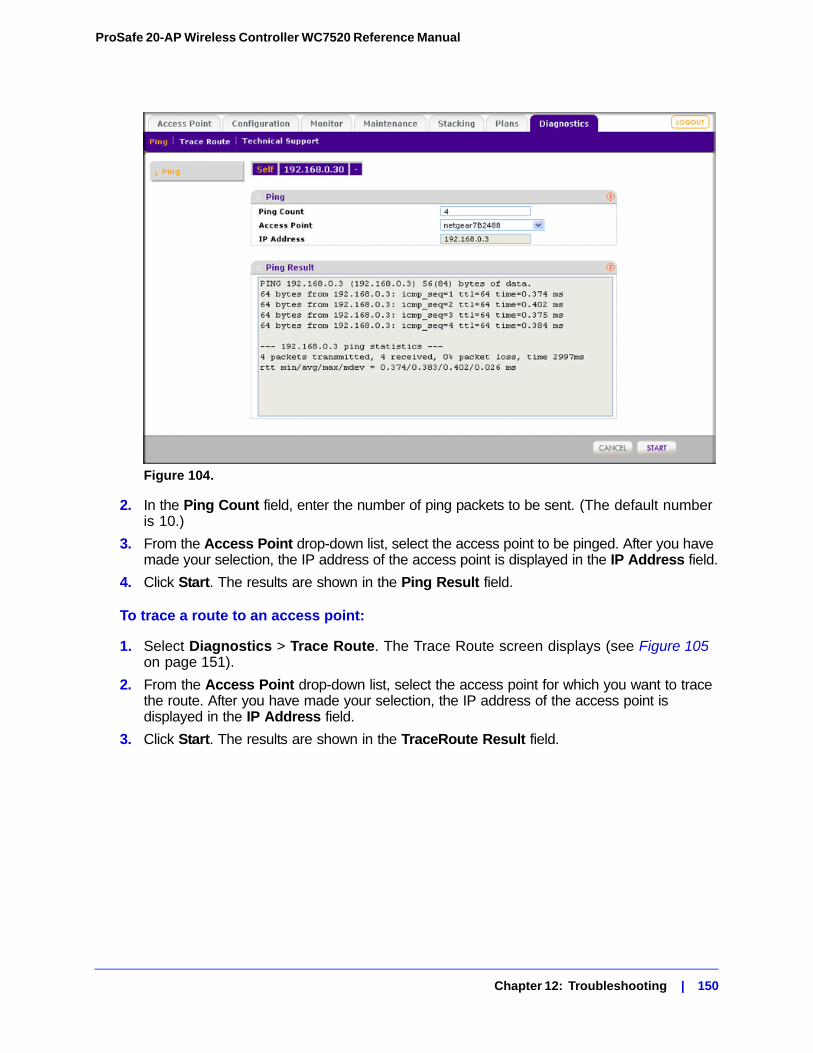
ProSafe 20-AP Wireless Controller WC7520 Reference Manual
Figure 104.
2. In the Ping Count field, enter the number of ping packets to be sent. (The default number is 10.)
3. From the Access Point drop-down list, select the access point to be pinged. After you have made your selection, the IP address of the access point is displayed in the IP Address field.
4. Click Start. The results are shown in the Ping Result field.
To trace a route to an access point:
1. Select Diagnostics > Trace Route. The Trace Route screen displays (see Figure 105 on page 151).
2. From the Access Point drop-down list, select the access point for which you want to trace the route. After you have made your selection, the IP address of the access point is displayed in the IP Address field.
3. Click Start. The results are shown in the TraceRoute Result field.
Chapter 12: Troubleshooting | 150
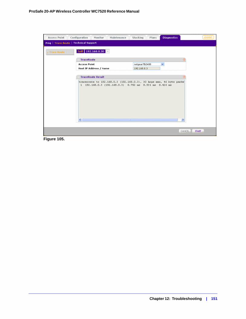
ProSafe 20-AP Wireless Controller WC7520 Reference Manual
Figure 105.
Chapter 12: Troubleshooting | 151
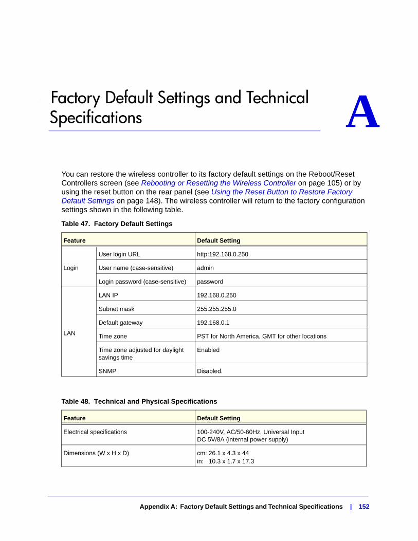
A. Factory Default Settings and Technical Specifications A
You can restore the wireless controller to its factory default settings on the Reboot/Reset Controllers screen (see Rebooting or Resetting the Wireless Controller on page 105) or by using the reset button on the rear panel (see Using the Reset Button to Restore Factory Default Settings on page 148). The wireless controller will return to the factory configuration settings shown in the following table.
Table 47. Factory Default Settings
Feature Default Setting
Login
User login URL http:192.168.0.250
User name (case-sensitive) admin
Login password (case-sensitive) password
LAN
LAN IP 192.168.0.250
Subnet mask 255.255.255.0
Default gateway 192.168.0.1
Time zone PST for North America, GMT for other locations
Time zone adjusted for daylight savings time
Enabled
SNMP Disabled.
Table 48. Technical and Physical Specifications
Feature Default Setting
Electrical specifications 100-240V, AC/50-60Hz, Universal Input DC 5V/8A (internal power supply)
Dimensions (W x H x D) cm: 26.1 x 4.3 x 44in: 10.3 x 1.7 x 17.3
Appendix A: Factory Default Settings and Technical Specifications | 152
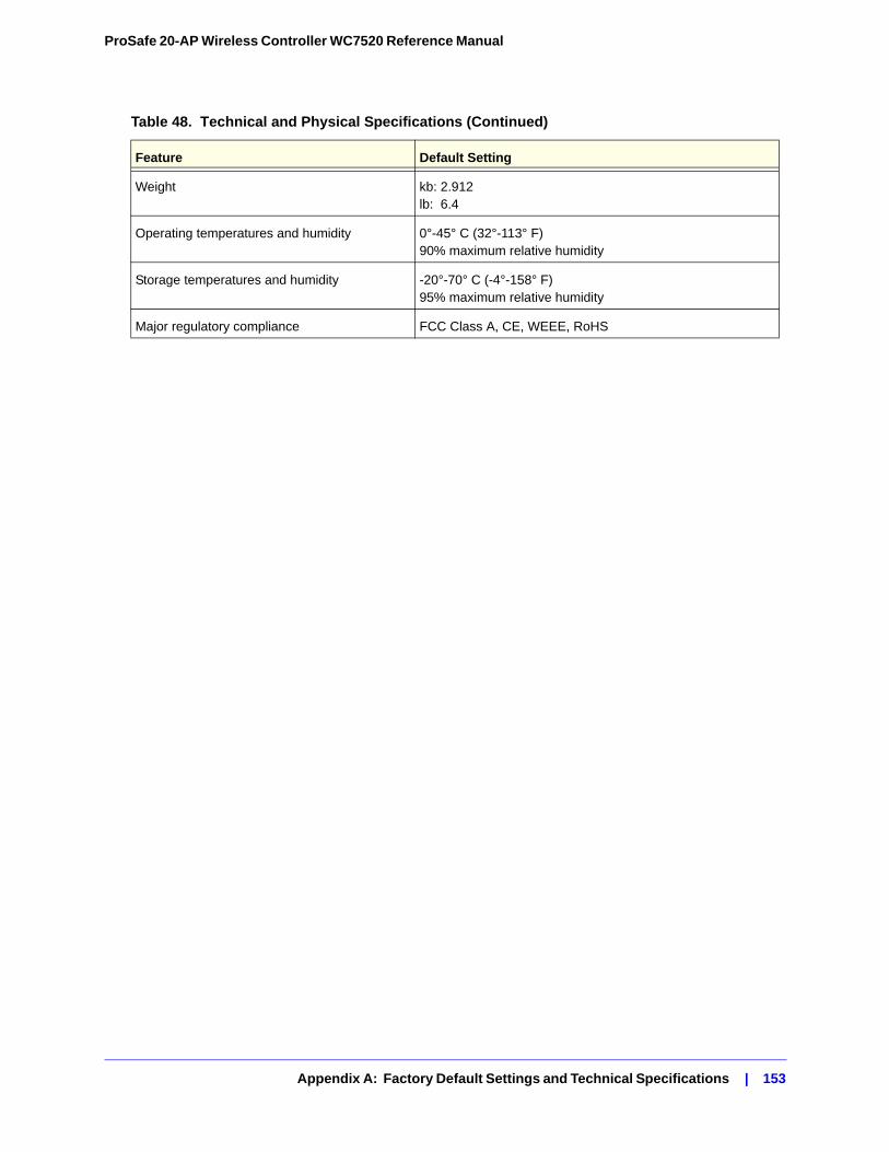
ProSafe 20-AP Wireless Controller WC7520 Reference Manual
Weight kb: 2.912lb: 6.4
Operating temperatures and humidity 0°-45° C (32°-113° F)90% maximum relative humidity
Storage temperatures and humidity -20°-70° C (-4°-158° F)95% maximum relative humidity
Major regulatory compliance FCC Class A, CE, WEEE, RoHS
Table 48. Technical and Physical Specifications (Continued)
Feature Default Setting
Appendix A: Factory Default Settings and Technical Specifications | 153
B. Notification of ComplianceNETGEAR Wired Products B
Certificate of the Manufacturer/ImporterIt is hereby certified that the ProSafe™ 20-AP Wireless Controller WC7520 has been suppressed in accordance with the conditions set out in the BMPT-AmtsblVfg 243/1991 and Vfg 46/1992. The operation of some equipment (for example, test transmitters) in accordance with the regulations may, however, be subject to certain restrictions. Please refer to the notes in the operating instructions.The Federal Office for Telecommunications Approvals has been notified of the placing of this equipment on the market and has been granted the right to test the series for compliance with the regulations.
Bestätigung des Herstellers/ImporteursEs wird hiermit bestätigt, daß das ProSafe™ 20-AP Wireless Controller WC7520 gemäß der im BMPT-AmtsblVfg 243/1991 und Vfg 46/1992 aufgeführten Bestimmungen entstört ist. Das vorschriftsmäßige Betreiben einiger Geräte (z.B. Testsender) kann jedoch gewissen Beschränkungen unterliegen. Lesen Sie dazu bitte die Anmerkungen in der Betriebsanleitung.
Das Bundesamt für Zulassungen in der Telekommunikation wurde davon unterrichtet, daß dieses Gerät auf den Markt gebracht wurde und es ist berechtigt, die Serie auf die Erfüllung der Vorschriften hin zu überprüfen.
FCC Caution• Any changes or modifications not expressly approved by the party responsible for compliance could void the user’s
authority to operate this equipment. • This device complies with Part 15 of the FCC Rules. Operation is subject to the following two conditions: (1) This
device may not cause harmful interference, and (2) this device must accept any interference received, including interference that may cause undesired operation.
Regulatory Compliance InformationThis section includes user requirements for operating this product in accordance with National laws for usage of radio spectrum and operation of radio devices. Failure of the end-user to comply with the applicable requirements may result in unlawful operation and adverse action against the end-user by the applicable National regulatory authority.
Note: This product’s firmware limits operation to only the channels allowed in a particular Region or Country. Therefore, all options described in this user's guide may not be available in your version of the product.
Europe – EU Declaration of Conformity
Marking by the above symbol indicates compliance with the Essential Requirements of the R&TTE Directive of the European Union (1999/5/EC). This equipment meets the following conformance standards:
EN300 328, EN301 489-17, EN60950
Appendix B: Notification of Compliance | 154
ProSafe 20-AP Wireless Controller WC7520 Reference Manual
For complete DoC please visit the NETGEAR EU Declarations of Conformity website at: http://kb.netgear.com/app/answers/detail/a_id/11621/
EDOC in Languages of the European Community
Cesky [Czech] NETGEAR Inc. tímto prohlašuje, že tento Radiolan je ve shode se základními požadavky a dalšími príslušnými ustanoveními smernice 1999/5/ES.
Dansk [Danish]
Undertegnede NETGEAR Inc. erklærer herved, at følgende udstyr Radiolan overholder de væsentlige krav og øvrige relevante krav i direktiv 1999/5/EF.
Deutsch [German]
Hiermit erklärt NETGEAR Inc., dass sich das Gerät Radiolan in Übereinstimmung mit den grundlegenden Anforderungen und den übrigen einschlägigen Bestimmungen der Richtlinie 1999/5/EG befindet.
Eesti [Estonian]
Käesolevaga kinnitab NETGEAR Inc. seadme Radiolan vastavust direktiivi 1999/5/EÜ põhinõuetele ja nimetatud direktiivist tulenevatele teistele asjakohastele sätetele.
English Hereby, NETGEAR Inc., declares that this Radiolan is in compliance with the essential requirements and other relevant provisions of Directive 1999/5/EC.
Español [Spanish]
Por medio de la presente NETGEAR Inc. declara que el Radiolan cumple con los requisitos esenciales y cualesquiera otras disposiciones aplicables o exigibles de la Directiva 1999/5/CE.
Ελληνική [Greek]
ΜΕ ΤΗΝ ΠΑΡΟΥΣΑ NETGEAR Inc. ΔΗΛΩΝΕΙ ΟΤΙ Radiolan ΣΥΜΜΟΡΦΩΝΕΤΑΙ ΠΡΟΣ ΤΙΣ ΟΥΣΙΩΔΕΙΣ ΑΠΑΙΤΗΣΕΙΣ ΚΑΙ ΤΙΣ ΛΟΙΠΕΣ ΣΧΕΤΙΚΕΣ ΔΙΑΤΑΞΕΙΣ ΤΗΣ ΟΔΗΓΙΑΣ 1999/5/ΕΚ.
Français [French]
Par la présente NETGEAR Inc. déclare que l'appareil Radiolan est conforme aux exigences essentielles et aux autres dispositions pertinentes de la directive 1999/5/CE.
Italiano [Italian] Con la presente NETGEAR Inc. dichiara che questo Radiolan è conforme ai requisiti essenziali ed alle altre disposizioni pertinenti stabilite dalla direttiva 1999/5/CE.
Latviski [Latvian]
Ar šo NETGEAR Inc. deklarē, ka Radiolan atbilst Direktīvas 1999/5/EK būtiskajām prasībām un citiem ar to saistītajiem noteikumiem.
Lietuvių [Lithuanian]
Šiuo NETGEAR Inc. deklaruoja, kad šis Radiolan atitinka esminius reikalavimus ir kitas 1999/5/EB Direktyvos nuostatas.
Nederlands [Dutch]
Hierbij verklaart NETGEAR Inc. dat het toestel Radiolan in overeenstemming is met de essentiële eisen en de andere relevante bepalingen van richtlijn 1999/5/EG.
Malti [Maltese] Hawnhekk, NETGEAR Inc., jiddikjara li dan Radiolan jikkonforma mal-htigijiet essenzjali u ma provvedimenti ohrajn relevanti li hemm fid-Dirrettiva 1999/5/EC.
Magyar [Hungarian]
Alulírott, NETGEAR Inc. nyilatkozom, hogy a Radiolan megfelel a vonatkozó alapvetõ követelményeknek és az 1999/5/EC irányelv egyéb elõírásainak.
Appendix B: Notification of Compliance | 155
ProSafe 20-AP Wireless Controller WC7520 Reference Manual
FCC Requirements for Operation in the United States
FCC Information to User
This product does not contain any user serviceable components and is to be used with approved antennas only. Any product changes or modifications will invalidate all applicable regulatory certifications and approvals
FCC Guidelines for Human Exposure
This equipment complies with FCC radiation exposure limits set forth for an uncontrolled environment. This equipment should be installed and operated with minimum distance of 20 cm between the radiator and your body.
This transmitter must not be co-located or operating in conjunction with any other antenna or transmitter.
FCC Declaration Of Conformity
We, NETGEAR, Inc., 350 East Plumeria Drive, Santa Clara, CA 95134, declare under our sole responsibility that the ProSafe™ 20-AP Wireless Controller WC7520 complies with Part 15 of FCC Rules. Operation is subject to the following two conditions:
• This device may not cause harmful interference, and• This device must accept any interference received, including interference that may cause undesired operation.
FCC Radio Frequency Interference Warnings & Instructions
This equipment has been tested and found to comply with the limits for a Class B digital device, pursuant to Part 15 of the FCC Rules. These limits are designed to provide reasonable protection against harmful interference in a residential installation. This equipment uses and can radiate radio frequency energy and, if not installed and used in accordance with the instructions, may cause harmful interference to radio communications. However, there is no guarantee that interference will not occur in a particular installation. If this equipment does cause harmful interference to radio or television reception, which can be determined by turning the equipment off and on, the user is encouraged to try to correct the interference by one or more of the following methods:
Polski [Polish] Niniejszym NETGEAR Inc. oświadcza, że Radiolan jest zgodny z zasadniczymi wymogami oraz pozostałymi stosownymi postanowieniami Dyrektywy 1999/5/EC.
Português [Portuguese]
NETGEAR Inc. declara que este Radiolan está conforme com os requisitos essenciais e outras disposições da Directiva 1999/5/CE.
Slovensko [Slovenian]
NETGEAR Inc. izjavlja, da je ta Radiolan v skladu z bistvenimi zahtevami in ostalimi relevantnimi določili direktive 1999/5/ES.
Slovensky [Slovak]
NETGEAR Inc. týmto vyhlasuje, že Radiolan spĺňa základné požiadavky a všetky príslušné ustanovenia Smernice 1999/5/ES.
Suomi [Finnish]
NETGEAR Inc. vakuuttaa täten että Radiolan tyyppinen laite on direktiivin 1999/5/EY oleellisten vaatimusten ja sitä koskevien direktiivin muiden ehtojen mukainen.
Svenska [Swedish]
Härmed intygar NETGEAR Inc. att denna Radiolan står I överensstämmelse med de väsentliga egenskapskrav och övriga relevanta bestämmelser som framgår av direktiv 1999/5/EG.
Íslenska [Icelandic]
Hér með lýsir NETGEAR Inc. yfir því að Radiolan er í samræmi við grunnkröfur og aðrar kröfur, sem gerðar eru í tilskipun 1999/5/EC.
Norsk [Norwegian]
NETGEAR Inc. erklærer herved at utstyret Radiolan er i samsvar med de grunnleggende krav og øvrige relevante krav i direktiv 1999/5/EF.
EDOC in Languages of the European Community
Appendix B: Notification of Compliance | 156
ProSafe 20-AP Wireless Controller WC7520 Reference Manual
• Reorient or relocate the receiving antenna.• Increase the separation between the equipment and the receiver.• Connect the equipment into an electrical outlet on a circuit different from that which the radio receiver is
connected.• Consult the dealer or an experienced radio/TV technician for help.
Modifications made to the product, unless expressly approved by NETGEAR, Inc., could void the user's right to operate the equipment.
Canadian Department of Communications Radio Interference RegulationsThis digital apparatus, (ProSafe™ 20-AP Wireless Controller WC7520), does not exceed the Class B limits for radio-noise emissions from digital apparatus as set out in the Radio Interference Regulations of the Canadian Department of Communications.
Canada ID: 4054A-FVX538
FOR HOME OR OFFICE USE
Tested to Complywith FCC Standards
PY306100037
ProSafe™ 20-AP Wireless Controller WC7520
Appendix B: Notification of Compliance | 157
Index
Numerics2.4 GHz and 5 GHz channels 75
802.11 wireless modes 71
802.1Q VLAN header 23, 58
AAC power socket 11
access point groupsassignment 66authentication servers 97basic (or default) 20description 20MAC authentication 94QoS 78radio, turning on and off 69rate limiting 82RF management 77security profiles 84wireless settings 72
access pointsadding 50discovery 46discovery results 49editing settings 52factory default state 47floor and building settings 53IP addresses 52IP subnet 48, 49known and unknown 91managed status 51pinging 149rebooting 107rogue
managing 89viewing in the network 126viewing on the managed access point 130viewing on the wireless controller 138
standalone mode 47supported models 13tracing a route 150troubleshooting 149viewing
in the network 128on the wireless controller 137security profiles 130
statistics 130VLAN settings 53
access, remotely 108
active SSIDs, viewing 142
advanced settings, description 19
AES 87
aggregation length 72
AIFS (Arbitration Inter-Frame Space) 79
alarmssettings 63viewing in the network 125viewing on the wireless controller 135
alerts, viewing 112
AMPDU (Aggregated Mac Protocol Data Unit) 72
authenticationcertificates 60methods supported 24servers 95
auto channel allocation 75
auto transmission power 76
Bbackground QoS queue 78
backing up the configuration 102
basic access point group 20
basic settings, description 19
beacon interval 72
best effort QoS queue 78
blacklisted clients, viewing 143
bottom label 12
broadcasting SSID 86
BSSID (Basic Service Set ID) 81
buildings, planning 39
button, reset factory defaults 11
Ccabling, troubleshooting 145
captive portal 98
captive portal users, viewing 141
certificates, authentication 60
Index | 158
ProSafe 20-AP Wireless Controller WC7520 Reference Manual
channel allocation 73
channel width 72
client separation 86
client VLANs 24, 27
clients, maximum number 80
clients, viewingblacklisted in the network 143in the network 125, 131, 142on the acess point 130on the wireless controller 135, 137
community names, SNMP 109
compliance information 154
configurationbacking up and restoring 102upgrading 103
connectivity test 22
console port 11
contents, package 9controller selection, stacking 121
country and region of operation 55
coverage area 42
coverage hole detection 77
customer information, licenses 118
CwMin and CwMax (Minimum or Maximum Contention Window) 79
Ddata encryption
configuring 86supported methods 24
data rate 71
date, troubleshooting 148
default access point group 20
default settings 11, 148, 152
detection, rogue access points 89
DHCPleases, viewing 140option 43 47server description 24server settings 59, 60
diagnostic tools 149
discovering access points 46
DNS servers 57
DTIM interval 72
Eelectrical specifications 152
email notification server 63
encryption, methods supported 24
external RADIUS server 95, 96
external storage 107
Ffactory default settings, wireless controller 11, 148, 152
factory default state, access points 47
failover, redundancy 121
features, overview 7, 13
firmwareupgrading 103version 127
floors, planning 39
fragmentation length 72
frequency band 41
FTP server, firmware upgrade 104
Ggroups. See access point groups.
guard interval 72
guest access 98
GUI. See Web management interface.
Hhard reset 105, 148
heat map 42
Iinterference sources 22
internal RADIUS server 95, 97
IP addressesaccess points 52DHCP server assignment 60license server 117redundancy settings 123SNMP manager 109stacking settings 121syslog server 62TFTP and FTP servers 104wireless controller 57
IP settingsaccess points 52wireless controller 57
IP subnetsaccess points 48, 49LAN 57troubleshooting 149
Index | 159
ProSafe 20-AP Wireless Controller WC7520 Reference Manual
KKensington lock 11
keys, licenses 116, 118
Llabel, bottom 12
LAN path, troubleshooting 147
LAN port LEDs 11, 145
LAN ports 10
layer 2 and 3 networks, auto discovery 48
LDAP server 96, 97
LEDsfront panel 10troubleshooting 144
licensesnumber and types required. 15redundancy group 122registering 118registration keys 116server settings 117viewing 116
load balancing 79
load balancing logs, viewing 113
location, placement 21
lock, Kensington 11
logsdownloading 110saving 111
MMAC authentication 93
management VLANs 23, 27, 58
master. See primary controller, stacking.
maximum burst length 79
maximum number of clients 80
memory partition 104
multicast routing 47
Nnetwork authentication 86
network status, viewing summary 125
network usage, viewing 126
notification server, emails 63
NTP (Network Time Protocol), client and server 56
number of clients, per radio 41
Ppackage contents 9partition, memory 104
password, restoring default 148
passwords, users 100
physical specifications 152
pinging, access points 149
PoE (Power over Ethernet), access points 13
portsconsole 11LAN 10USB 10
Power LED 10, 144
power socket, AC 11
preamble type 72
primary controller, stacking 120
product label 12
profile groups. See access point groups.
QQoS (quality of service) 78
Rrack-mounting 21
radio, turning on and off 69
RADIUS servers 95
rate limit logs, viewing 114
rate limiting 81
rebootingaccess points 107wireless controller 105, 148
redundancy 121
redundancy logs, viewing 114
registration keys, licenses 116, 118
remote access 108
requirementsauto discovery 46redundancy 122RF planning
access points 40overview 37
reset button 11
resetting, wireless controller 105
restoringconfiguration 102password 148
RFlogs, viewing 113management 75
Index | 160
ProSafe 20-AP Wireless Controller WC7520 Reference Manual
obstructions 22
RIFS transmission 72
rogue access pointsmanaging 89viewing
in the network 126on the managed access point 130on the wireless controller 136, 138
RSSI (received signal strength indication) 42, 80
RTS threshold 72
Sscheduling, firmware updates 104
secondary controller, stacking 120
security profilesconfiguring 85, 87managing 83viewing in the network 134viewing on the access point 130viewing on the wireless controller 139
self, controller selection 121
self-healing 77
session timeout 110
signal quality 41
signal strength 79
slave. See secondary controller, stacking.
sniffer 146
SNMP 108, 109
soft reset 105
spectrum analysis 22
SSID (Service Set ID or wireless network name) 86
stacking 119
stacking logs, viewing 115
standalone mode, access points 47
storage, external 107
subnet masksaccess point 52DHCP server 60wireless controller 57
support, NETGEAR 16
syslog server 61
system alerts, viewing 112
system logs, saving 111
TTCP/IP network, troubleshooting 147
technical sprecifications 152
technical support 2temperatures and humidity 153
Test LED 10, 145
TFTP server, firmware upgrade 104
time and time zoneconfiguring 56troubleshooting 148
time-out error 147
timeout, sessions 110
TKIP 87
tracing a route 150
trademarks 2trap port, SNMP 109
troubleshootingaccess points 149basic functioning 144configuration settings, using sniffer 146date 148diagnostic tools 149LAN path 147LEDs 144pinging access points 149restoring factory default settings 148TCP/IP network 147time and time zone 148time-out error 147tracing an access point route 150Web management interface 145
TXOP (transmission opportunity) limit 79
Uuntagged VLANs 58
upgrading firmware 103
USB port 10
users, managing 100
VVAR information, licenses 118
video QoS queue 78
VLANs 58client 24, 27DHCP server 60management 23, 27security profiles 86settings, access points 53untagged 58
voice QoS queue 78
VRRP (Virtual Router Redundancy Protocol) 121
WWC7510L license 15
WC75NL license 15
Index | 161
ProSafe 20-AP Wireless Controller WC7520 Reference Manual
Web management interfacedescription 16troubleshooting 145
WEP encryption 87
WINS servers 57
wired connection, stacking 119
wireless band usage, viewingin the network 126on the wireless controller 136
wireless client separation 86
wireless clients, maximum number 80
wireless clients, viewingblacklisted in the network 143in the network 125, 131, 142on the acess point 130on the wireless controller 135, 137
wireless controller, viewingactive SSIDs 142captive portal users 141DHCP leases 140in the network 127summary 135usage 136
wireless modes 71
wireless settings 71
WMM (Wi-Fi multimedia) 78
WNAP210 13
WNDAP350 13
WPA encryption 87
Index | 162


![Prosafe SE (PRS) · 6020 EmployeesWebsite Cyprus Exchange PRS [Oslo Stock Exchange] Industry Company Overview Prosafe SE (Prosafe) is a provider of semi-submersible accommodation](https://img.pdfslide.net/doc/110x75/6015be59df313a7c091a033d/prosafe-se-prs-6020-employeeswebsite-cyprus-exchange-prs-oslo-stock-exchange.jpg)