Embed Size (px)
Citation preview
ProSafe-DSPwith PLS, Programmable Logic Solveror SLS, Solid-state Logic Solver
Technical Product Description
© Yokogawa ISSProSafe is a registered mark of Yokogawa Industrial Safety Systems. All other brand or productnames are trademarks of their respective owners.Information in this document is subject to change without notice and does not represent a commitment on the part of Yokogawa ISS.
2
1 Preface
The ProSafe-DSP system is a Safety
Instrumented System (SIS) that was
designed for applications, which
require the highest Safety Integrity
Levels (SIL). For the DSP: ‘Dedicated
Safety Processor’ a selection can be
made between a programmable logic-
solver (PLS) or a solid-state logic-
solver (SLS).
Both technologies are capable of
executing all typical Safety tasks, as
well as the related supplementary non-
Safety functions. This comprises
interfacing with a Man-Machine-
Interface (MMI), Distributed Control
System (DCS), Sequence of Event
Recording (SER), a SCADA s y s t e m ,
e t c .
This manual will familiarise the
reader with the merits of the ProSafe-
D S P system, created by the unique
system design, setting it apart from
conventional software-based Safety
P L C ’s.
The aspects of Safety and Fault-
tolerance are discussed, as well as the
system structure, configuration, the
communication capabilities and
s p e c i f i c a t i o n s .
In particular the powerful System
Engineering Tool (SET) is highlighted.
It facilitates the engineering,
programming and maintenance
procedures; furthermore it creates the
project documentation.
3
Table of contents
Chapter 1 P r e f a c e 2
Chapter 2 I n t r o d u c t i o n 4
Chapter 3 Safety requirements in Industry 5
- Introduction to Safety Instrumented Systems (SIS) 5
- Inherently fail-safe & fault-tolerant? 7
Chapter 4 The ProSafe-DSP system concept 9
- The DSP or Dedicated Safety Processor 9
- Comparison Safety PLC’s vs ProSafe-DSP 9
- The ProSafe-DSP Av a i l a b i l i t y 1 0
- The ProSafe-DSP S e r v i c e a b i l i t y 1 0
- The SLS technology 1 0
- The PLS technology & system concept 1 2
Chapter 5 The ProSafe-DSP Communication capabilities 1 6
- The communication interface ProSafe-COM 1 6
- Sequence of Event Recording 1 7
- Auxiliary non-safety related Input &Output modules 1 7
- MMI, Man Machine Interface 1 8
Chapter 6 Project realisation 1 9
- The ProSafe-DSP SET System Engineering To o l 1 9
- Test & Maintenance 2 0
- System Acceptance Te s t i n g 2 1
- Factory Acceptance Testing 2 1
- Commissioning & proof testing on-site 2 2
Chapter 7 P r o S a f e - D S P specifications & performance 2 3
- Generic system specifications 2 3
- The SLS & PLS modules description 2 5
- Input modules 2 5
- Discrete Output modules 2 6
- Solid-state Output modules 2 7
- Logic & Timer modules 2 8
- ProSafe-DSP Auxiliary modules 3 0
- Clock, power & communication modules 3 1
- The ProSafe-COM modular communication interface 3 2
Chapter 8 Glossary of terms 3 5
Chapter 9 Yokogawa ISS serving Industrial Safety 3 7

4
2 Introduction
The ProSafe-DSP system is based on
the Dedicated Safety Processor (DSP),
that is employed in a fault-tolerant
architecture. Its sophisticated design
and superior Safety performance have
created the Safety reference standard
for programmable as well as for
solid–state Safety Instrumented
Systems (SIS). The modular design
allows fault-tolerant structures to
achieve very high Av a i l a b i l i t y, without
affecting the superior Safety
p e r f o r m a n c e .
A radical improvement provided by the
P r o S a f e - D S P system, is the
elimination of software for an
operating system and for the self-
diagnostics. Instead a unique inherent
self-test technology is employed,
throughout the safety-related parts of
the ProSafe-DSP s y s t e m .
Furthermore the life-cycle cost is
relatively low as a result of a design-
lifetime exceeding 15 years, and the
powerful engineering and maintenance
System Engineering Tool. In addition,
by the absence of system software, the
need for costly and risky software
updates is also non-existent.
Typical user applications are found in
the Chemical, Refining, Oil & Gas
production and Nuclear &
conventional Power industry, such as:
•Emergency Shut-Down systems
(ESD) for Safety critical process
u n i t s ;
•High-Integrity Protection Systems
(HIPS ) for well-heads, pipelines,
natural Gas storage installations;
•Chemical process plants for critical
process protection;
•Well-head protection systems, also in
sub-sea applications;
•Burner Management Systems for
incinerator furnaces and steam
b o i l e r s ;
•Compressor protection systems for
rotating and piston type compressors;
•Fire & Gas protection systems as
found in Oil & Gas installations;
•High-Integrity protection systems in
the Nuclear industry.
5
‘Eliminating the unexpected’
The current Safety considerations
focus on three elements:
•The physical separation of the Safety
interlocks and process control
s y s t e m s ;
•The nature of the SIS technology
u s e d ;
•Quantitative risk assessment (QRA)
methods, which enable to optimise
the links of the Safety chain
including the field devices.
This first element is a matter of
engineering design practice. Physical
separation of process control and
Safety interlocks will eliminate
common-cause problems that can
originate from hardware, software and
human causes.
The second element offers essentially
two alternatives technologies to
c o n s i d e r. One based on PLC’s
(Programmable Logic Controllers),
typically incorporating test-circuits
and test-software. A s u p e r i o r
alternative is the use of technology
that employs an ‘inherent self-test’ o f
the ProSafe-DSP, whereby the ‘fail-to-
s a f e ’ nature is achieved by this unique
t e c h n o l o g y, without the need for
additional hardware or software for
s e l f - d i a g n o s t i c s .
The quest for higher Safety
The guidelines for safe operation of
Industrial installations in the
Petrochemical and oil and gas
production are becoming more and
more severe by International Safety
standards, developed by the IEC.
Safety standards, such as the new IEC
6 1 5 0 8 / 6 1 5 11, are developed by co-
operation of industry groups, Safety
certifying agencies and insurance
companies, resulting in more stringent
regulation and legislation.
Operating companies are aware, that a
reliable Safety Instrumented System
(SIS) is of great value, not only
because of the legal and insurance
l i a b i l i t y. It serves to provide protection
for people, environment and to
safeguard the large scale investments,
that are involved in today’s production
p r o c e s s e s .
On the other hand, unnecessary
interruptions of a production process
must be avoided, because this aspect of
process ‘availability’ has a direct
relation with production yield and cost.
Furthermore there also exists an
indirect and positive correlation
between Availability and Safety.
Availability is therefore an integral
part of the design of a reliable SIS.
It is important to emphasise that
availability by fault-tolerance, is
another phenomenon than Safety, and
to be aware that these two benefits are
created by different design strategies.
The combination of these two elements
in one design requires a specific
attention for the facets of common-
cause effects and the self-diagnostic
c a p a b i l i t y.
3 Safety requirements in Industry
Introduction to Safety Instrumented Systems (SIS)
6
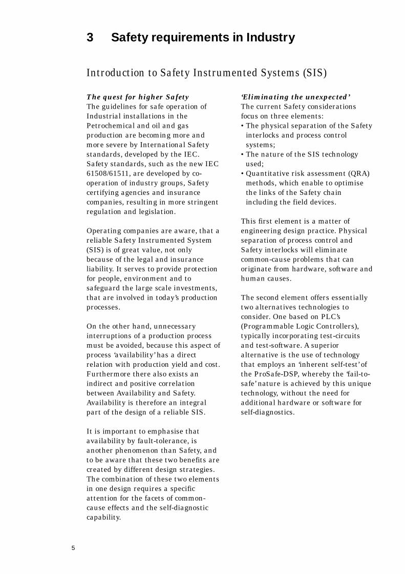
In many instances it is advantageous
to compose the system from various
types of hardware, dedicated to the
specific tasks. These ‘hybrid’ s y s t e m s
make it possible to exploit the
advantages technologies. The use of
‘inherently fail-safe’ technology is
creating the highest Safety level. On
the other hand, microprocessor based
devices provide the flexibility, the
interface facilities and additional
f u n c t i o n a l i t y. The ProSafe-DSP s y s t e m
is in fact such a unique ‘hybrid
system’, that combines the advantages
of both technologies.
The third element of contemporary
Safety approach is the Safety
assessment by QRA, a quantitative
risk assessment that calculates
realistic figures for Safety (Pfd & SIL)
and Availability (MTNF & FTR) for
each project. This will make sure that
the SIS will perform according to
expectations and conforms to the
required Safety Integrity Levels. The
S I L requirement depends on the
Safety risk that is provoked by
operating a certain type of process. In
practice, it ranks from 1 for the less
critical processes, up to 4 for the most
Safety critical processes.
Safety standards such as IEC
6 1 5 0 8 / 6 1 5 11 and DIN/VDE V 19250
that have world-wide recognition have
created stringent Safety requirements
for process plants. Therefore the
operating companies in the process
industry are looking for system
suppliers, that can offer tightly
integrated control and Safety systems.
In the Yokogawa ISS project-
organisation a department of
specialists guarantees adherence to
Safety standards and can issue a
‘certificate of conformity’ for an
individual project.
A hybrid system configuration.
7
Inherently fail-safe & fault-
tolerant?
The use of the terms ‘fault-tolerance’ &
‘ r e d u n d a n c y ’ may give many users a
feeling of confidence, which is not
always justified. It should be noted
that fault-tolerance is only a method to
provide an elevated level of
Availability if applied properly.
Full or partial redundancy with
‘ v o t i n g ’ can be applied in any type of
modular technology on the Inputs, the
logic-solver and the output modules. In
a redundant configuration the voter
serves to compare the performance of
the system modules and to make a
selection, based on the requirement of
Safety and/or availability. In general
an attempt to increase Safety by
redundant modules goes at the
expense of Av a i l a b i l i t y, because of
increased hardware use and additional
s o f t w a r e .
Also visa-versa: a configuration for
increased Availability creates a lower
S a f e t y, because the ‘diagnostic
c o v e r a g e - f a c t o r’ in all types of
redundant systems has a dominating
influence on the system SIL level, if
this figure is less than 0.99.
The limiting factors are the un-
detected failures, common-cause
failures, software execution time and
hardware reliability. The un-detected
failures that remain (and can
accumulate!) in the system, are due to
the limited testability of software and
of complex hardware. By definition,
redundancy and voting devices are no
remedy for this type of un-safe
f a i l u r e s .
Since in the ProSafe-DSP system the
diagnostic coverage factor 1 for the
’inherent self-test’ and the safety is not
affected by redundancy. By a modular
design of the ProSafe-DSP system it
can be configured in a fault-tolerant
m a n n e r, which is done for applications
where this is a prerequisite besides
un-compromised Safety.
For example, in a High Integrity
Process Safety (HIPS) system a 2 out
of 3 voting can be applied on the
Inputs only. This will improve the
reliability of the input process
parameters, since the field sensors
(transmitters) and actuators (valves)
often have a relative high failure-rate
and do contribute to the SIL
calculation.
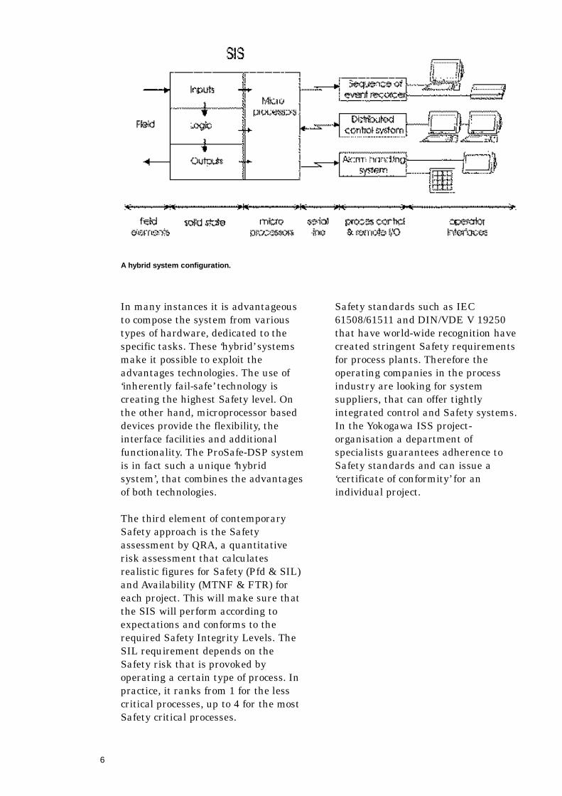
The relation between ‘SIL’ and the
‘ M i s s i o n - t i m e ’
The necessary proof-test intervals are
becoming shorter if the diagnostic
covers less than 100 %. This real
coverage-factor does comprise the
percentage of un-tested hardware and
s o f t w a r e !
It is this phenomenon of Safety-
degradation necessitates a periodical
off-line test of a Safety system. For the
user it is important to have a test-
interval time that is exceeding the
‘ m i s s i o n - t i m e ’ of the process, otherwise
a process shut-down is required to do
this periodical ‘proof-test’.
The relation between Safety Integrity Level (SIL)and the mission-time.
8
Often the quoted diagnostic coverage-
factors are ‘an expert’s opinion’, having
only a qualitative significance. In the
recent decade, scientific developments
have created more realistic
quantitative validation methods of
Safety and the self-test capability of
systems. In practice, this figure is
dominating the calculation of the
Safety Integrity Level (SIL), provided
by a system and the field devices.
Common-cause faults
Systems that employ redundancy are
in particular vulnerable for common-
cause faults. Similar redundancy may
be a good method to improve the
systems availability, for systems that
have apparently too many failures. For
improving safety, the effect of
redundancy is limited, or even counter
productive, since it will introduce
common-cause failures. In practice,
redundant safety PLC systems do
apply similar hardware and only
single software.
Redundancy when applied in parallel
brings a degree of fault-tolerance, not
to be confused with safety. Fault-
tolerance and safety are benefits,
which are achieved by dissimilar
design strategies.
9
The DSP or Dedicated
Safety Processor
The unique technology of the ProSafe-
D S P can employ either the program-
mable logic solver (PLS) or the solid-
state logic solver (SLS). The non-
safety functions and computer inter-
faces are implemented with regular
microprocessor technology.
The Dedicated Safety Processor has
been designed with the objective of an
uncompromising safeguarding system,
of which the Safety Integrity Level is
eminent and verifiable. The unique
technology employed in the PLS
concept has created today’s reference
standard for programmable & solid-
state SIS systems. The robust safety
achievement is originating from its
internal architecture and inherent self-
test methodology. Also the elimination
of all system software is a major
breakthrough for a programmable
safety system.
The DSP design has successfully
eliminated all known sources of un-
safe failures. In each DSP system the
inherent self-test is performed, in
every small functional unit, while
working with the real functional logic
code of the application. This further
implies, that the logic processing and
self-test are executed at exactly the
same moment in time and by the same
components of the hardware.
4 The ProSafe-DSP system concept
Comparison between Safety PLC’s and the ProSafe-DSP:
Safety PLC’s P r o S a f e - D S P
Software for firmware & diagnostics M e g a b y t e s n o n e
Software for application M e g a b y t e s max. 375 bytes per ‘box’
D i a g n o s t i c s by software & hardware by inherent self-test
Soft-error detection by voting by inherent self-test
F a u l t - t o l e r a n c e y e s y e s
Redundancy voting by software & hardware inherently safe
‘ C o m m o n - c a u s e ’ e l e m e n t s s o f t w a r e / v o t i n g / s y n c h r o n i s a t i o n n o n e
Separation Safety & other functions no, all in same processor y e s
Subdivision of systems p o s s i b l e by design
Communication capabilities y e s y e s
S c a n - t i m e 50 - 1000 milliseconds 1 millisecond
R e s p o n s e - t i m e 100 - 2000 milliseconds 25 millisecond
P r o g r a m m i n g various languages FLD drawings in A u t o C a d
PLS: in EEPROM
SLS: interconnections
of modules
Safety Level S I L 2 & 3, AK 4-6 S I L 4, AK 6-7
‘ M i s s i o n - t i m e ’ & test interval several months many years
10
The SLS technology
Safety-by-design
The essence of the SLS, solid-state
logic solver The ProSafe-DSP S L S
principle was invented in 1965 and in
the mean time has been utilised in a
large number of SIS installations in
the hydrocarbon, the chemical and the
(nuclear) power industry. This techno-
l o g y, formerly known as ‘MagLog’ h a s
been upgraded using up-to-date
components and fabrication methods,
without changing the basic inherently-
Safety principle.
P r o S a f e - D S P SLS Inherently
f a i l - s a f e
The SLS technology is called
‘inherently fail-safe’, meaning that by
the self-testing nature of the basic SLS
circuit it will act fail-safe, without the
necessity of utilising additional test- or
diagnostic circuits.
A logical ‘1’-signal status in a SLS
system that reflects the ‘safe’ c o n d i t i o n
of a process parameter is represented
by a pulse-train, keeping the SLS
circuits dynamic continuously. The
logic solver operations are executed by
magnetic core elements, while the
transistors only serve to restore the
energy of the pulse-trains.
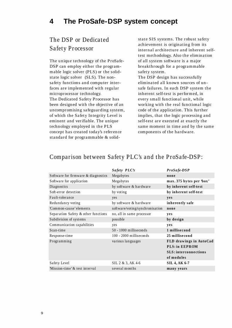
The ProSafe-DSP SLS principle
The essential element of the SLS
circuit is a ring-shaped core of
magnetic material with several
windings. This basic circuit further
consists of a transistor and pulse-
shaping circuit that comprises a choke
coil and a diode.
The ring-shaped magnetic core is not a
normal transformer, since it has a very
high hysteresis, which makes it a
binary element with two stable
positions and it serves a dual purpose.
First it can execute logical functions
(AND, OR, NOT) and secondly it does
provide a galvanic isolation between
SLS circuits.
The ProSafe-DSP
Availability
Products in the ProSafe-DSP r a n g e
have been designed from the outset, to
give the highest level of reliability
required in control Systems where
failures can be costly and hazardous.
As a result of the simplicity, the low
parts count, the components de-rating,
the functional tolerance for component
parameters drift and last but not least
the high EMI immunity, the SLS
system also scores very high on the
scale of Availability (FTR & MTNF).
For extremely high demands regarding
Availability the SLS modules can be
duplicated freely.
The ProSafe-DSP
Serviceability
Serviceability is inherent in the design
is a prime feature of all ProSafe
S y s t e m s .
In case of a detected failure, the faulty
module can be replaced quickly
without interfering with other
subsystems. Modules do not require
system specific configuration or
addressing when replaced, and all
module upgrades are retro-compatible.
Normally skilled personnel can easily
replace modules on the basis of testing
every logic step in the system. Te s t
facilities are permanently integrated
in the system and are enhanced when
using the ProSafe-COM facility.
11
Current pulse-trains are used to
magnetise the magnetic cores. The
duty-cycle is less than 3%, which keeps
the circuit dissipation low. As an extra
benefit, as a result of this current
principle the low circuit impedances
make the circuit immune to high levels
of electro-magnetic interference.
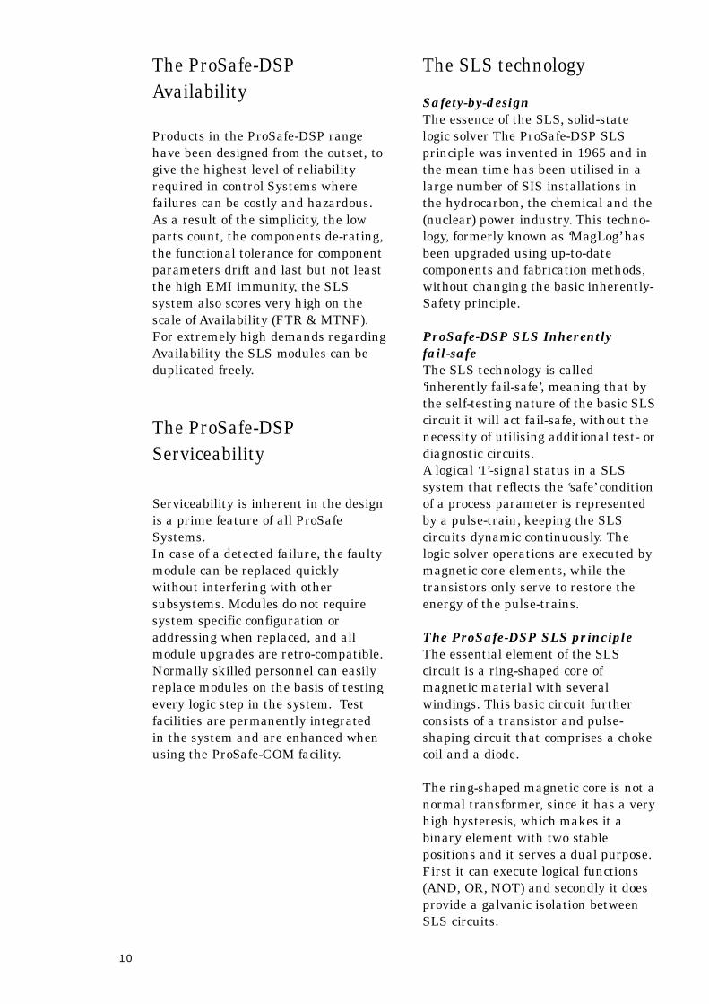
The logical ‘1’ input information, from
a closed field contact for example, is
represented by a pulse-train of 1000
short pulses per second in the SLS
circuit; we call them ‘A’ pulses. Each
SLS circuit needs these ‘A’ as well as
phase shifted ‘B’ pulses, which may
come from an other logic input or from
the system clock generator.
These ‘A’ and ‘B’ current pulse-trains
have an asymmetrical shape, meaning
that the current flows in one direction
only and therefore are only capable to
magnetise the core in only one
direction (clockwise or anti-clockwise).
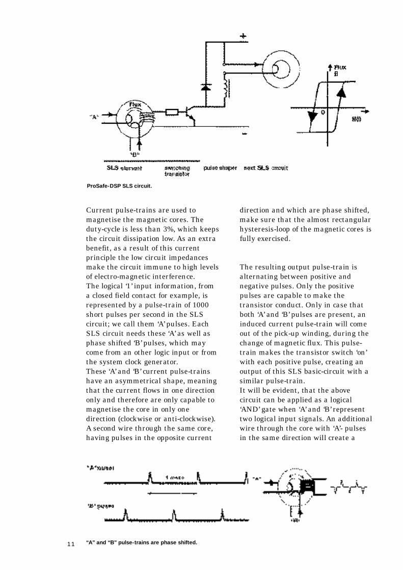
A second wire through the same core,
having pulses in the opposite current
direction and which are phase shifted,
make sure that the almost rectangular
hysteresis-loop of the magnetic cores is
fully exercised.
The resulting output pulse-train is
alternating between positive and
negative pulses. Only the positive
pulses are capable to make the
transistor conduct. Only in case that
both ‘A’ and ‘B’ pulses are present, an
induced current pulse-train will come
out of the pick-up winding, during the
change of magnetic flux. This pulse-
train makes the transistor switch ‘on’
with each positive pulse, creating an
output of this SLS basic-circuit with a
similar pulse-train.
It will be evident, that the above
circuit can be applied as a logical
‘ A N D ’ gate when ‘A’ and ‘B’ r e p r e s e n t
two logical input signals. An additional
wire through the core with ‘A’- pulses
in the same direction will create a
“A” and “B” pulse-trains are phase shifted.
ProSafe-DSP SLS circuit.
12
logical ‘OR’ gate, assuming that the ‘B’
pulses come from the system clock.
The output will always go to a static
de-energised state, whenever any
component failure or a wire failure
occurs. Because only discrete
components are applied, the circuit
failure behaviour is fully predictable.
The dynamic nature of the circuit
takes care of a continuous self-test, by
activating all components and
electrical connections. The unique
combination of the mentioned design
aspects make the SLS circuits
‘ i n h e r e n t l y ’ fail-safe.
The PLS technology &
system concept
The PLS programmable logic solver
has been designed without any
compromise and the Safety Integrity
Level is eminent and verifiable.
The hardware consists of a kernel that
employs virtual hardware diversity
and redundancy, while working with
the real functional logic code of the
application. Input and output circuits
apply the inherently fail-safe SLS
t e c h n o l o g y. The PLS logic solver is
located in the Logic & Timer or ‘LT ’
module, and it executes all functional
logic and timer functions, as defined in
the application Functional Logic
D i a g r a m .
The Logic & Timer modules, power
supplies, I/O modules and the
supporting modules can be structured
in a number of configurations. In this
way it is possible to further increase
the Availability by fault-tolerance, or
to choose for a lower safety integrity
level for the protection of a less-critical
p r o c e s s .
“A” and “B” pulses are needed to go out through the hysteresis loop.
13
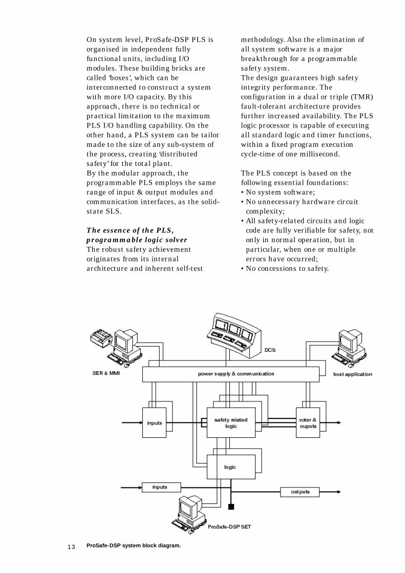
On system level, ProSafe-DSP PLS is
organised in independent fully
functional units, including I/O
modules. These building bricks are
called ‘boxes’, which can be
interconnected to construct a system
with more I/O capacity. By this
approach, there is no technical or
practical limitation to the maximum
PLS I/O handling capability. On the
other hand, a PLS system can be tailor
made to the size of any sub-system of
the process, creating ‘distributed
s a f e t y ’ for the total plant.
By the modular approach, the
programmable PLS employs the same
range of input & output modules and
communication interfaces, as the solid-
state SLS.
The essence of the PLS,
programmable logic solver
The robust safety achievement
originates from its internal
architecture and inherent self-test
m e t h o d o l o g y. Also the elimination of
all system software is a major
breakthrough for a programmable
safety system.
The design guarantees high safety
integrity performance. The
configuration in a dual or triple (TMR)
fault-tolerant architecture provides
further increased availability. The PLS
logic processor is capable of executing
all standard logic and timer functions,
within a fixed program execution
cycle-time of one millisecond.
The PLS concept is based on the
following essential foundations:
•No system software;
•No unnecessary hardware circuit
c o m p l e x i t y ;
•All safety-related circuits and logic
code are fully verifiable for safety, not
only in normal operation, but in
p a r t i c u l a r, when one or multiple
errors have occurred;
•No concessions to safety.
ProSafe-DSP system block diagram.
14
The PLS design has successfully
abandoned the conventional
architecture of regular
microprocessors and is capable to
disarm the well-known internal
potential failures. Besides the
capability to detect static failures, the
PLS is also well equipped to detect
dynamic failures or ‘soft-errors’, which
emerge from critical timing, or
electromagnetic interference. These
soft errors are driven by the moment
of operation and cannot be revealed by
a regular off-line functional test.
The PLS employs the fundamental
principle of blending logic processing
with a full inherent self-test, executed
at the same moment in time. As a
consequence the inherent self-test
occurs with real field input-data, while
processing the actual functional
application logic in ‘virtual instruction
d i v e r s i t y ’ and by usage of the same
hardware components involved. A l l
logic processing is driven by the
system hardware structure.
This patented inherent self-testing
method applies ‘virtual hardware
d i v e r s i t y ’ and transformation of input
data from the process and logic
programme instructions. Static and all
dynamic failures or potential selection
failures in registers, are cancelled in
this manner. The PLS employs tightly
coupled ‘state-machines’, which are
again inherently self-testing by design.
All logic timers are dual-redundant
and are built in dedicated hardware,
each with an error detection circuit.
This detection circuit is activated by
any discrepancy between the timers
Outputs. Since the ultimate test for a
timer is using the timer, this test is
similar to the normal operation. For
this test, each timer is activated for
the programmed time and after its
expiration, this procedure is repeated
c o n t i n u o u s l y. For regular operation
each timer is reset and started
i n s t a n t a n e o u s l y, by the functional
l o g i c .
Safety measures on system level
The ProSafe-DSP PLS system design
is based on the following design
p r i n c i p l e s :
•The PLS system has totally
abandoned the use of system
software. Instead, the operation is
driven by the hardware structure.
The application-code reflecting the
FLD functionality, is typically only a
few hundred bytes for one PLS ‘box’;
•The PLS system logic solvers do not
have any cross connections by shared
control, data or other resources. A l s o
other means of influencing the
operation of a peer’s logic solver are
a b s e n t ;
•Application instructions are retained
twice in EEPROM in a diverse mode;
•No usage of any conventional
memory for data retention. Instead
the Outputs are set by inherently-
safe magnetic cores, that are
refreshed every millisecond by the
P L S ;
•Usage of inherently fail-safe circuits
similar to SLS wherever possible.
The above principles remain valid
when multiple PLS boxes are
interconnected to create more input &
output handling capacity. The fully
autonomous PLS boxes operate as
parallel processors for the total system
logic. In this manner the system scan-
time of 1 millisecond remains
independent of the total I/O count,
which is virtually unlimited.
15
P r o S a f e - D S P PLS system
c o n f i g u r a t i o n
The smallest PLS system is called a
‘box’. Each PLS ‘box’ is in essence a
complete safety system, containing all
modules to create a safety system. A
box can accommodate the following
m o d u l e s :
•Two Communication & Power (CP-
180) modules, which work in a
redundant mode. Besides the system
power provision, these modules also
support the inter- m o d u l e
communication for status and events;
•A PLS ‘box-pair’ utilises the CP-180
modules located in the left side box;
•Two inherently fail-safe digital input
modules, each with 16 channels;
•Three logic & timer modules, each
containing a PLS logic processor;
•Two inherently fail-safe output
modules, each with 8 channels.
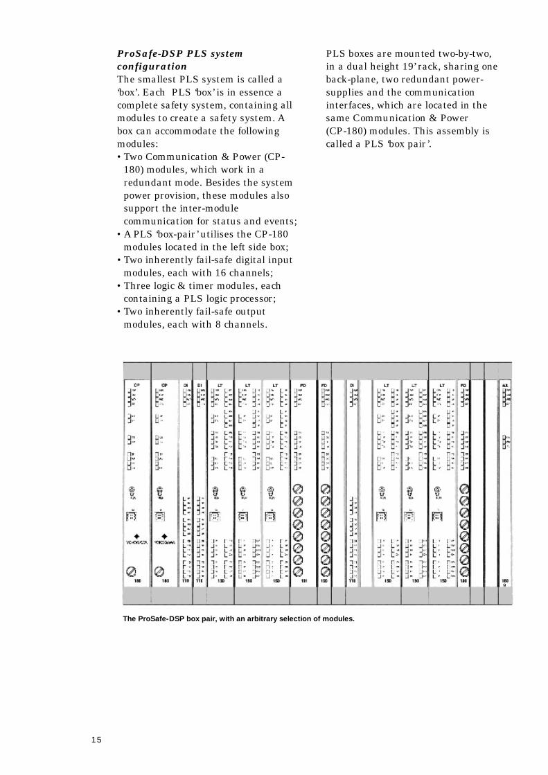
PLS boxes are mounted two-by-two,
in a dual height 19’ rack, sharing one
back-plane, two redundant power-
supplies and the communication
interfaces, which are located in the
same Communication & Power
(CP-180) modules. This assembly is
called a PLS ‘box pair’ .
The ProSafe-DSP box pair, with an arbitrary selection of modules.
16
5 The ProSafe-DSP Communicationcapabilities
The Communication interface ProSafe-COM
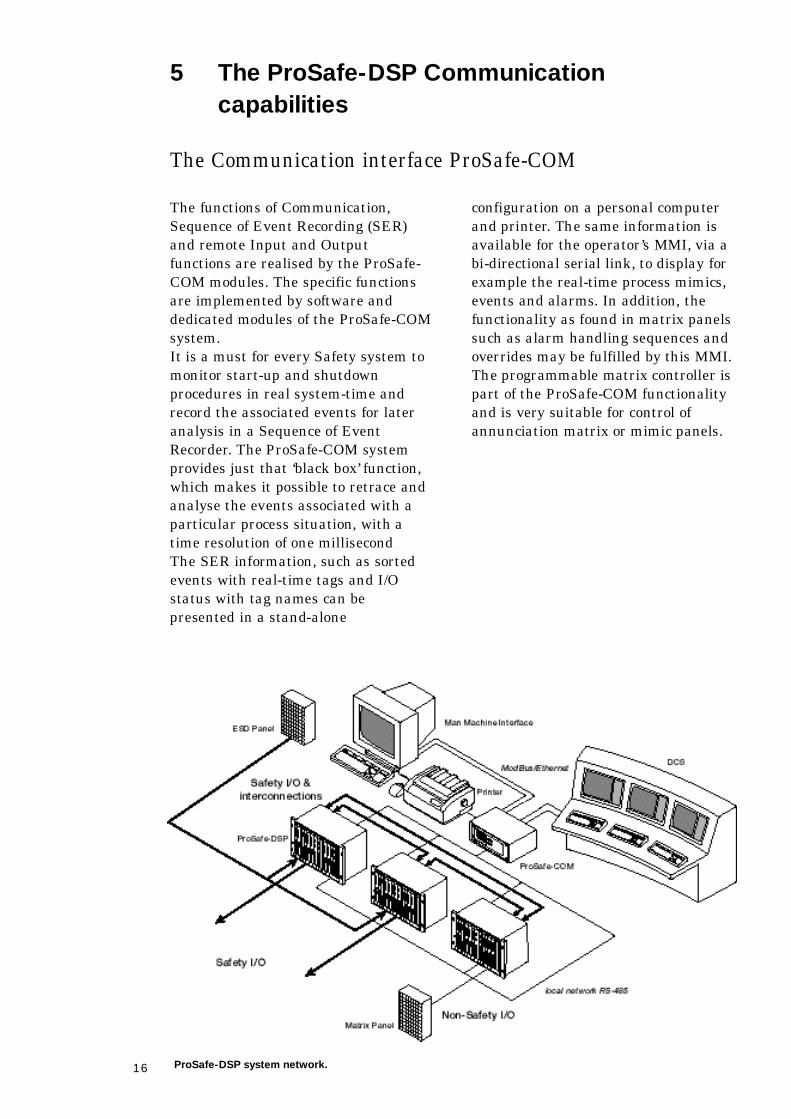
The functions of Communication,
Sequence of Event Recording (SER)
and remote Input and Output
functions are realised by the ProSafe-
COM modules. The specific functions
are implemented by software and
dedicated modules of the ProSafe-COM
s y s t e m .
It is a must for every Safety system to
monitor start-up and shutdown
procedures in real system-time and
record the associated events for later
analysis in a Sequence of Event
R e c o r d e r. The ProSafe-COM system
provides just that ‘black box’ f u n c t i o n ,
which makes it possible to retrace and
analyse the events associated with a
particular process situation, with a
time resolution of one millisecond
The SER information, such as sorted
events with real-time tags and I/O
status with tag names can be
presented in a stand-alone
configuration on a personal computer
and printer. The same information is
available for the operator’s MMI, via a
bi-directional serial link, to display for
example the real-time process mimics,
events and alarms. In addition, the
functionality as found in matrix panels
such as alarm handling sequences and
overrides may be fulfilled by this MMI.
The programmable matrix controller is
part of the ProSafe-COM functionality
and is very suitable for control of
annunciation matrix or mimic panels.
ProSafe-DSP system network.
17
The MMI man machine interface
provides the operator with all
pertinent information on the screen
from the underlying Safety systems
and it enables all necessary
interventions, protected by
authorisation levels, and hardwired
override permissions. In practice most
functions of an annunciation matrix
panel and the ProSafe-COM can be
conveyed to this operator MMI. The
MMI supervisory system offers
extensive report capabilities to
summarise all operator and process
activities in daily reports.
Sequence of Event
Recording
In the ProSafe-COM system, the
sequence of event recorder system
fulfils the functions of:
•Data communication of:
- events;
- status;
- analogue values;
- real-time clock setting for
synchronisation with the host
computer system;
- override & inhibit capability of
Inputs and Outputs via dedicated
modules that handle the non-safety
I / O .
•High-speed time-tagging of events at
input level, for accurate real-time
i n f o r m a t i o n ;
•Data buffer capacity prevents loss of
data if communication with the host
system is slow or interrupted;
•Fault-isolation is guarantied by
virtue of built-in precautions, for
connections to the Safety- related
system modules. The safety integrity
of these devices is hereby maintained;
•Cost effective modular design, which
can be configured for virtually any
a p p l i c a t i o n ;
•Redundant serial data
communication with DCS and any
other host application system,
supporting the Ethernet TCP/IP &
ModBus interface protocols;
•Printer output;
•Time resolution of 1 millisecond;
•Max. 5000 signals per ProSafe-COM
s y s t e m ;
•Storage buffer for 10.000 events.
Virtually unlimited storage capacity
in the ProSafe-COM workstation or
in the MMI.
Auxiliary non-Safety
related Input & Output
modules
Additional modules of the ProSafe-
COM system can handle non-safety-
critical I/O in a cost-effective manner,
such as for the control of annunciation
matrix and mimic panels:
•Bi-directional serial communication
with other systems, operating as a
master or as a slave, utilising the
ModBus protocol;
•Sequence handling for alarm systems
or other non-safety functions;
•Many standard alarm sequences,
first-up handling and other function-
blocks, which are readily available in
the engineering tool.

18
The MMI, a supervisory
VDU workstation
The Man Machine Interface for the
operator can supervise all distributed
safety systems as well as associated
functions during process start-up,
normal operation and SER data
processing for later analysis. It
comprises for example:
•Real-time presentation of process
mimics on the VDU;
•Alarm and start-up sequence
h a n d l i n g ;
•Events presentation and sorting by
period and by sub-system;
•First-out indication, also on
individual sub-systems;
•Override and disable capability such
a s :
- permit control;
- disable all, disable group;
- number of overrides limitation;
- duration limitation.
•Extensive report capabilities;
•Data retention is virtually unlimited
in the workstation;
•System-time synchronisation
capability with other systems.
19
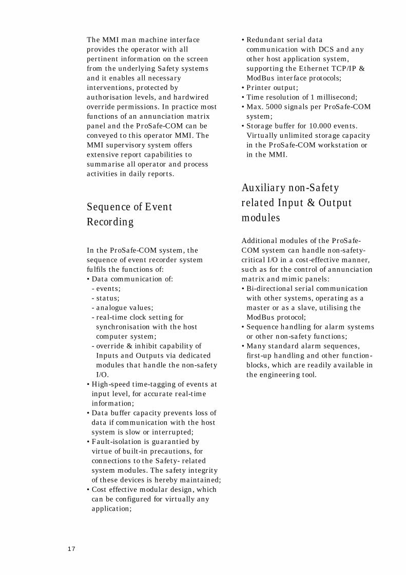
Computer A i d e d
Engineering and
programming of
P r o S a f e - D S P s y s t e m
applications is fully
supervised by the PC
based, engineering
system working under
Windows. It serves to
create an engineering
environment, where all
engineering activities
are co-ordinated and
d o c u m e n t e d .
The ProSafe-DSP S E T
does allow the project
engineer to fully employ
his expertise and
preferences for system
layout and the creation of autonomous
sub-systems.
During the engineering process, the
SET is assisting the engineer, by
examining the created AutoCAD based
system drawings. Messages, warnings
and suggestions are generated
automatically in case of mismatch of
hardware usage, or potential safety
conflicts. In order to verify the
functional logic, the engineer can
simulate the functional design, not
only on ProSafe ‘box’ level, but also
through the entire ProSafe-DSP
s y s t e m .
After engineering completion, SET will
compile all engineering
documentation, including the
complementary project documentation,
such as mechanical drawings, wire-
lists and of course the PLS instruction
code files.
Not only during engineering, but also
extending to the whole useful life of
the realised project, the System
Engineering Tool organises the
consistency of project files. The SET
keeps track of all revisions and
changes of the application drawing
package. In this way, the SET provides
up-to-date project documentation,
safeguarding not only the quality of
engineering, but in particular serving
the interest of safety.
6 Project realisation
ProSafe-DSP SET, System Engineering Tool
Functional Logic Diagram in design stage.
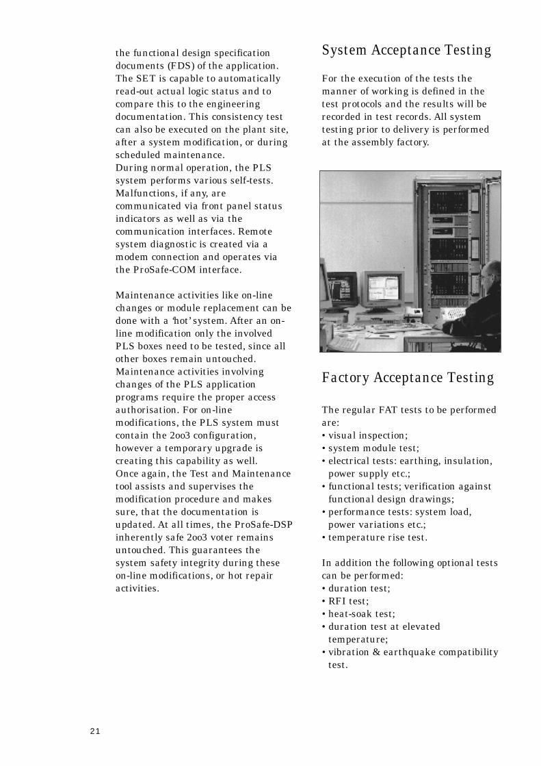
Window showing system configuration.20
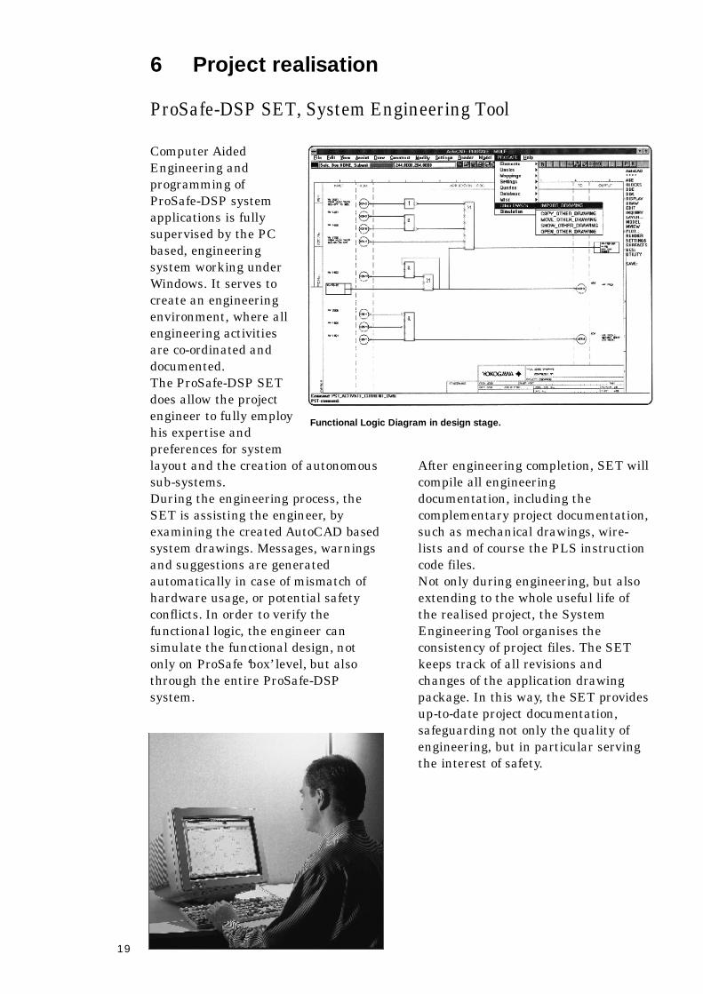
PC hardware, minimal requirements:
•Personal Computer, Pentium, with
min. 32 MB operating memory;
•The use of a 17 inch colour monitor;
•A function-tablet is recommended.
Operation by means of a mouse is
also possible.
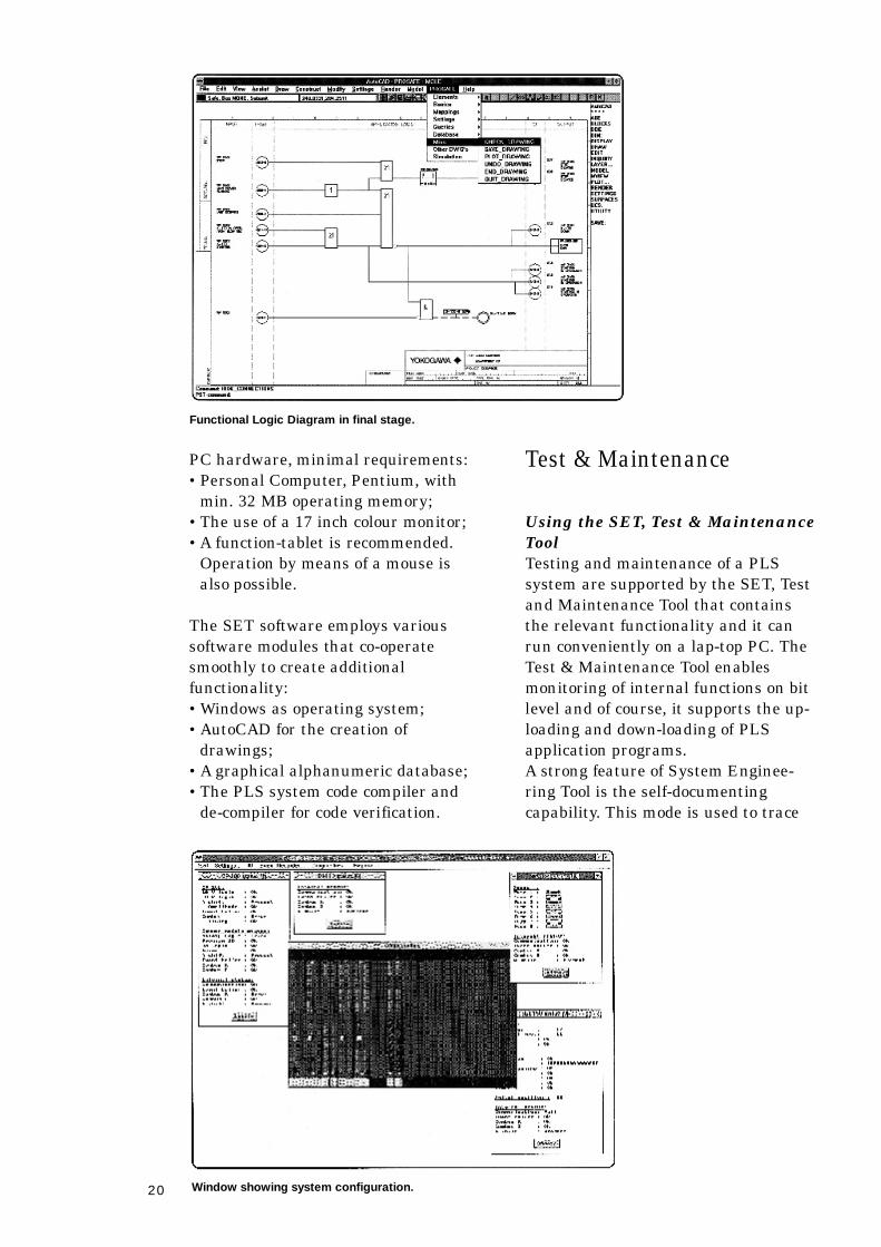
The SET software employs various
software modules that co-operate
smoothly to create additional
f u n c t i o n a l i t y :
•Windows as operating system;
•AutoCAD for the creation of
d r a w i n g s ;
•A graphical alphanumeric database;
•The PLS system code compiler and
de-compiler for code verification.
Functional Logic Diagram in final stage.
Test & Maintenance
Using the SET, Test & Maintenance
To o l
Testing and maintenance of a PLS
system are supported by the SET, Te s t
and Maintenance Tool that contains
the relevant functionality and it can
run conveniently on a lap-top PC. The
Test & Maintenance Tool enables
monitoring of internal functions on bit
level and of course, it supports the up-
loading and down-loading of PLS
application programs.
A strong feature of System Enginee-
ring Tool is the self-documenting
c a p a b i l i t y. This mode is used to trace
21
the functional design specification
documents (FDS) of the application.
The SET is capable to automatically
read-out actual logic status and to
compare this to the engineering
documentation. This consistency test
can also be executed on the plant site,
after a system modification, or during
scheduled maintenance.
During normal operation, the PLS
system performs various self-tests.
Malfunctions, if any, are
communicated via front panel status
indicators as well as via the
communication interfaces. Remote
system diagnostic is created via a
modem connection and operates via
the ProSafe-COM interface.
Maintenance activities like on-line
changes or module replacement can be
done with a ‘hot’ system. After an on-
line modification only the involved
PLS boxes need to be tested, since all
other boxes remain untouched.
Maintenance activities involving
changes of the PLS application
programs require the proper access
authorisation. For on-line
modifications, the PLS system must
contain the 2oo3 configuration,
however a temporary upgrade is
creating this capability as well.
Once again, the Test and Maintenance
tool assists and supervises the
modification procedure and makes
sure, that the documentation is
updated. At all times, the ProSafe-DSP
inherently safe 2oo3 voter remains
untouched. This guarantees the
system safety integrity during these
on-line modifications, or hot repair
a c t i v i t i e s .
System Acceptance Testing
For the execution of the tests the
manner of working is defined in the
test protocols and the results will be
recorded in test records. All system
testing prior to delivery is performed
at the assembly factory.
Factory Acceptance Testing
The regular FAT tests to be performed
a r e :
•visual inspection;
•system module test;
•electrical tests: earthing, insulation,
power supply etc.;
•functional tests; verification against
functional design drawings;
•performance tests: system load,
power variations etc.;
•temperature rise test.
In addition the following optional tests
can be performed:
•duration test;
•RFI test;
•heat-soak test;
•duration test at elevated
temperature;
•vibration & earthquake compatibility
t e s t .
22
Commissioning &
integrated proof-testing
on-site
On completion of installation and
commissioning at site, a final site test
will be performed. This test will
generally include all tests made in the
Factory Acceptance test, using portable
simulators or actual plant Inputs and
Outputs. The testing may be
supplemented by additional tests
required as a result of any changes
incorporated into the system since the
FAT.
The logic-solver of the DSP s y s t e m
utilises inherently fail-safe modules
and inherently self-testing dynamic
logic, therefore there is no requirement
for system input, output and logic
testing once the system has been put
in operation.
Volt free contact (VFC) Outputs and
timer cards are the only components
requiring periodic testing due to their
non inherently fail-safe characteristics,
though full reliability data is available
for these modules to support reliability
p r e d i c t i o n s .
Testing of field input loops is provided
by applying overrides to the relevant
Inputs and simulating a trip in the
field. The logic allows the true detected
state to be monitored and handed off
for recording if desired. Testing of
output devices should be based on
confirmation that they will trip on
demand. This requires that Outputs
should allow individual manual trip
functions, whilst not permitting
Outputs to be prevented from tripping.
This can be provided by switches on
the 24Vdc., supplied to each output
circuit where a purpose built test
facility is desired. A low cost option is
simply to open the isolating pins in the
field termination.
Where there is a specific desire for
output defeats, then these can be
applied to allow a full system trip to be
carried out on-line. If the ProSafe-
COM system is included in the system,
then a full event log of the test is
available in the SER, for comparison
against an original record.
23
7 ProSafe-DSP specifications & performance
Generic system specifications:
Principle of operation:
in SLS: Magnetic Core Transistor Logic-solver;
in PLS: Hardware-driven logic-solver for max. 375 machine
instructions per PLS box;
in both: Inherent self-test and Fail-safe Inputs & Outputs.
Special Features:
Inherently fail-safe;
Low heat dissipation;
High immunity to EMI;
Galvanic separation of logic-solver and I/O;
Auxiliary microprocessors for:
- C o m m u n i c a t i o n ;
-SER diagnostics;
- M o n i t o r i n g ;
- A n n u n c i a t i o n .
Operating environmental conditions:
Te m p e r a t u r e : operating -20 C to +70 C.
Relative humidity: 0 – 98 % ‘non condensing’.
S h o c k : 10g, 16 millisecond
Vi b r a t i o n : 10 - 200 Hz at 1.5g.
S y s t e m : Seismic qualification.
P o l l u t i o n : SO2, H2S. < 0.7 PPM.
M e c h a n i c a l : SLS: Eurocard modules.
PLS: double-height Eurocard modules, 266mm.
assembly in: 19’ r a c k s .
cabinets: 800x2100x600 (or 800)mm, (wxhxd).
Maximum number of Inputs & Outputs:
I n p u t s : u n l i m i t e d .
O u t p u t s : u n l i m i t e d .
Ti m e r s : u n l i m i t e d .
Noise immunity conforms to:
CE: Conformité Europeén;
EN 50081-2 & 50082-2;
ENV 1954, IEC 11 3 1 - 2 ;
C . I . S . P.R. 16;
DIN IEC 801-2, 3, 4.
Input range:
D i s c r e t e : 24 VdC
Analogue: 0-20 mA, 0-10 V or 0-5 VdC, set point & measured
transmitter value readable by serial link;
Thermocouple & R.T. D : by signal conditioning before analogue input;
C o m m u n i c a t i o n : D S P Inputs via ModBus and Ethernet.
Output range:
Relay: DC and A C
Fail-safe: 5 Watts & 20 Watts; 24 VdC or 110 VdC
Serial links: by ModBus
Timer range:
Multipurpose timer: 7 millisecond to 70 hours.
Dual fail-safe timer: 1.5 to 310 seconds.
24
In addition, the ProSafe-DSP s y s t e m
was assessed for Safety and
Availability by the following
o r g a n i s a t i o n s :
•S I N T E F ;
•T N O ;
•W I B ;
•K E M A ;
•S I R E P Evaluation Report
E 1699 S 91;
•University of Twenthe CAIRO study;
•University of Eindhoven RIFIT study.
The ProSafe-DSP system satisfies the
recommendations of the following
guidelines for SIS systems:
•IEC standards 61508 & 61511 ;
•I S A SP84 recommendations;
•Department of Energy - Guidance
note 91, on Design of Offshore
I n s t a l l a t i o n s ;
•HSE Health & Safety Executive,
PES/SIS documents 1 and 2;
•E E M U A Publication 160 – ‘Category
1 ’ a p p l i c a t i o n s ;
•API R14C.
Logic processing:
S c a n - t i m e : 1 millisecond for I/O scan and logic processing
Response time: 1 millisecond per logic element.
Ty p i c a l l y, 25 msec. end-to-end includes I/O delay
C o m m u n i c a t i o n :
Serial link standard via: ModBus protocol (RS 232) or Protocol to customer
s p e c i f i c a t i o n s .
P o i n t - t o - p o i n t : via Input & Output modules.
Self diagnostic:
ProSafe-COM microprocessor system with SER
L E D ’s on modules.
Programming & Engineering:
For PLS: ProSafe-DSP SET using IEC or ISA logic
s y m b o l s .
For SLS: Engineering by ProSafe-DSP S E T, also for
software programming of the auxiliary microprocessor
functions including ProSafe-COM.
Hardwired programming of the Safety interlocks with
protected cold crimp-contacts (IP 2 0 ) .
Trouble shooting:
Self-diagnostic by sequence of event recorder and
LED status indicators on all modules.
Safety certifications:
T Ü V: AK 6-7
Factory Mutual: SIL 3 - 4
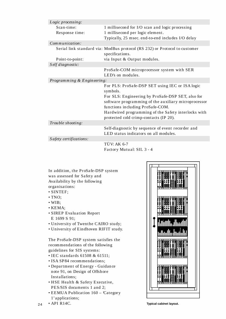
Typical cabinet layout.
25
Field I/O termination
Field termination is realised by means
of connector-blocks for direct plug-in of
system cables, or by terminal rows
that facilitate marshalling.
The SLS and PLS modules
description
For a ProSafe-DSP SLS system we
summarise the various categories of
available modules:
•Input modules;
•Logic & Timer modules;
•Output modules;
•Auxiliary modules;
•Communication & Interface modules.
The next chapters describe the
functionality in more detail. For a
detailed technical specification, we
refer to the individual datasheet of
each module.
Input modules
Digital input module DI-511 for the
S L S
The discrete Input module has 8
channels and converts field voltage
Inputs to inherently fail-safe, pulse-
train signals. The module performs
continuos self-test every millisecond.
It has the following characteristics:
•8 digital Inputs at nominal 24 Vdc.;
•status indication per channel by
L E D ’s at the front;
•Input current of 8.5 mA, at 18 - 32
V d c . ;
•each individual input is galvanically
i s o l a t e d ;
•monitoring circuit for interfacing
with the ProSafe-COM.
Digital input module DI-110 for the
P L S
The inherently fail-safe digital input
module DI-110 converts 16 digital field
Inputs into 16 pulse train signals. The
signal conversion uses inherently fail-
safe technology, with all Inputs
galvanically isolated. The module has
the following features:
•a continuous inherent self-test is
executed every millisecond;
•16 digital Inputs at nominal 24 Vdc.;
•LED status indication per channel at
the front;
•input current of 8.5 mA, at 18 - 32
V d c . ;
•each individual input is galvanically
i s o l a t e d .
The data communication circuit for
status and sequence of event monito-
ring also executes a continuous self-
test. It will report the healthiness of
the communication-related part to the
Clock-Power module CP-180 on a
routine basis. Diagnostic information
is indicated at the front panel and any
abnormal condition will result in an
alarm indication on the common alarm
line, contained on the bus reserved for
this purpose. The module communica-
tion responds to communication
requests from the communication sub-
system located in the clock-power
module CP-180 and reports status and
event information.
Besides the communication informa-
tion for status and event-data, the
module also responds to create the
following system-messages:
•event time stamp;
•communication reset;
•status of communication related part
of the module;
•module identity code and communica-
tion of the software version code.
Each PLS box can accommodate a
maximum of two DI-110 digital input
modules, each with 16 input circuits.
Therefore, the maximum number of
digital fail-safe Inputs for a ProSafe-
D S P Box is 32.
26
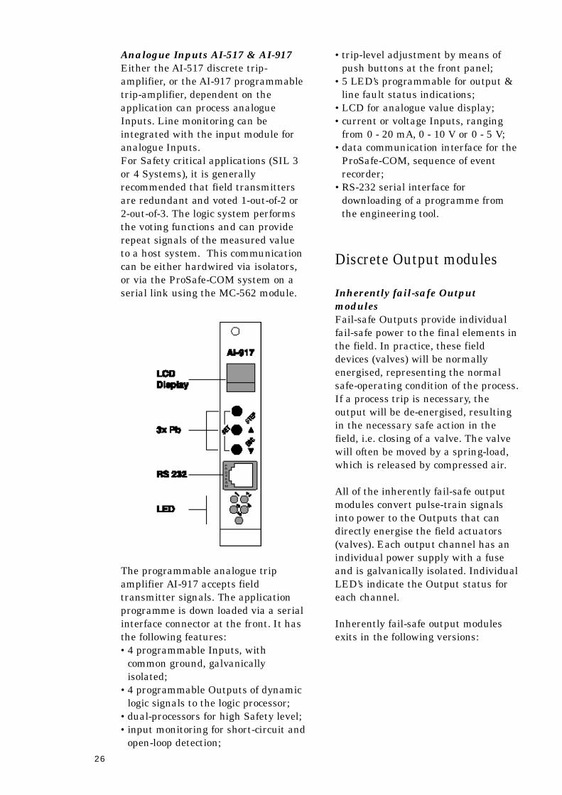
Analogue Inputs AI-517 & AI-917
Either the AI-517 discrete trip-
a m p l i f i e r, or the AI-917 programmable
t r i p - a m p l i f i e r, dependent on the
application can process analogue
Inputs. Line monitoring can be
integrated with the input module for
analogue Inputs.
For Safety critical applications (SIL 3
or 4 Systems), it is generally
recommended that field transmitters
are redundant and voted 1-out-of-2 or
2-out-of-3. The logic system performs
the voting functions and can provide
repeat signals of the measured value
to a host system. This communication
can be either hardwired via isolators,
or via the ProSafe-COM system on a
serial link using the MC-562 module.
The programmable analogue trip
amplifier AI-917 accepts field
transmitter signals. The application
programme is down loaded via a serial
interface connector at the front. It has
the following features:
•4 programmable Inputs, with
common ground, galvanically
i s o l a t e d ;
•4 programmable Outputs of dynamic
logic signals to the logic processor;
•dual-processors for high Safety level;
•input monitoring for short-circuit and
open-loop detection;
•trip-level adjustment by means of
push buttons at the front panel;
•5 LED’s programmable for output &
line fault status indications;
•LCD for analogue value display;
•current or voltage Inputs, ranging
from 0 - 20 mA, 0 - 10 V or 0 - 5 V;
•data communication interface for the
ProSafe-COM, sequence of event
recorder;
•RS-232 serial interface for
downloading of a programme from
the engineering tool.
Discrete Output modules
Inherently fail-safe Output
m o d u l e s
Fail-safe Outputs provide individual
fail-safe power to the final elements in
the field. In practice, these field
devices (valves) will be normally
energised, representing the normal
safe-operating condition of the process.
If a process trip is necessary, the
output will be de-energised, resulting
in the necessary safe action in the
field, i.e. closing of a valve. The valve
will often be moved by a spring-load,
which is released by compressed air.
All of the inherently fail-safe output
modules convert pulse-train signals
into power to the Outputs that can
directly energise the field actuators
(valves). Each output channel has an
individual power supply with a fuse
and is galvanically isolated. Individual
L E D ’s indicate the Output status for
each channel.
Inherently fail-safe output modules
exits in the following versions:
27
FO-526 inherently fail-safe output
m o d u l e
This module is for 3 channels
providing 24 or 48Vdc., max. 20 Wa t t .
FO-528 inherently fail-safe output
m o d u l e
This module is for 2 channels
providing 24 or 110 Vdc., max. 35
Wa t t .
FO-529 inherently fail-safe output
m o d u l e
This module is for 4 channels
providing 24 Vdc., max. 0.5 Watt.
FO-120 & FO-121 inherently fail-
safe output module
Both modules are designed for the
programmable PLS and have eight
channel fail-safe Outputs, nominal 24
Vdc at the front and LED status
indication. The module contains also
the voting circuit for redundant logic-
pulses, coming from the LT-150, Logic
& Timer modules.
The unique inherently fail-safe
technology is also applied for the
voting of the logic Outputs entering
from the LT-modules. The logic-pulses
are voted 2 out of 3, or 2 out of 2
depending on the chosen configuration.
The module contains a communication
interface that serves to transfer the
status and it stores all events of the
DC field Outputs. In addition, the
fuse-status of each field power supply
is monitored via the communication
module. Diagnostic information about
the communication is shown at the
front panel. Any error condition
activates the common alarm on the
b u s .
The Power supply capacity of each
channel is 5 Watt for FO-120 and 20
Watt for FO-121. The PLS Box can
accommodate a maximum of two fail-
safe power output modules, either 2
each 8 channel 5 Watt, or one 8
channel 20 Watt, or one of each type.
Therefore the maximum number of
inherently fail-safe Outputs for a PLS
Box is 16.
Solid-state Output modules
Matrix panel lamp drivers & Relay
output modules:
IO-547 lamp-driver module
This module is designed to control
matrix panel lamps or LED’s. It has 8
circuits with the following
c h a r a c t e r i s t i c s :
•24 Vdc. Inputs;
•24 Vdc. current sink Outputs;
•8 LED’s indicate the activated
O u t p u t s ;
•galvanic isolation by opto-couplers;
•inverted or direct acting;
•common lamp test and flash input;
•shift-register for the ProSafe-COM
i n t e r f a c e .
DO-523 relays Output module
This module is intended for use as a
lamp or relay-driver and converts 8
pulse-train Input signals in solid-state
Outputs for 8 channels. Inputs &
Outputs are galvanically isolated.
Each output includes a protection
diode and a fuse. LED’s indicate the
activated Outputs.
RE-520 relays Output module
The module is intended for the
connection of medium and low power
loads. It converts 24Vdc. Input signals
into Outputs for 8 channels, voltage
free, double throw contacts, rated for
24 Vdc., 0.5 Amp. The channel input
status is indicated by LED’s. The
Inputs and Outputs are galvanically
i s o l a t e d .
DO-521 relays Output module
This module is intended for the
connection of high loads. It converts 6
pulse-train signals into voltage-free
output contacts, rated for 2.5 A m p .
The channel input status is indicated
by LED’s. The Outputs are
galvanically isolated.
28
RE-522 relays Output module
This module is applied as a contact-
multiplier for 4 channels and can be
configured in various ways. Contacts
are rated for 0.5 Amp., 24 Vdc. The
input status is indicated by 4 LED’s .
DO-524 relays Output module
This module is intended for the
connection of small loads. It converts 8
pulse-train signals into voltage-free
output contacts, rated for 0.5 A m p .
The channel input status is indicated
by LED’s. The Outputs are
galvanically isolated.
FG-525 normally de-energised
O u t p u t
For Outputs that are normally de-
energised or ‘energise-to-trip’ t h i s
module is applied. It provides failure
detection in the OFF-state on the
board as well as field loop line
monitoring both for open and short-
circuit. A common fault-annunciation
output will hold a memory until the
next reset.
The Input of pulse-train signals for 2
channels is converted into 24 Vdc., 20
watt. The 6 LED’s indicate for 2
channels: Output voltage, normal
operation and error.
This module is designed for use in Fire
& Gas systems for deluge and other
extinguisher Outputs.
Logic & Timer modules
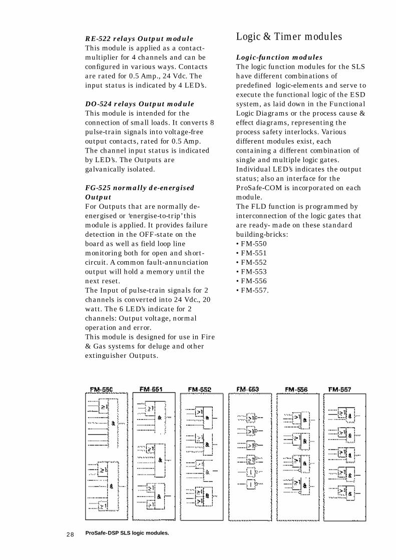
Logic-function modules
The logic function modules for the SLS
have different combinations of
predefined logic-elements and serve to
execute the functional logic of the ESD
system, as laid down in the Functional
Logic Diagrams or the process cause &
effect diagrams, representing the
process safety interlocks. Va r i o u s
different modules exist, each
containing a different combination of
single and multiple logic gates.
Individual LED’s indicates the output
status; also an interface for the
ProSafe-COM is incorporated on each
m o d u l e .
The FLD function is programmed by
interconnection of the logic gates that
are ready- made on these standard
b u i l d i n g - b r i c k s :
•FM-550
•F M - 5 5 1
•F M - 5 5 2
•F M - 5 5 3
•F M - 5 5 6
•F M - 5 5 7 .
ProSafe-DSP SLS logic modules.
29
TI-540 redundant timer module
The module contains two multiple-
function timers with logic pulse-train
input & output. The operating
principle is based on counting the
system clock pulses. For fail-safe
applications the two timers should be
used in a 2 input AND gate. The range
can be set between 7 msec. and 70
hours by means of strapping on the
mating connector. The various timer
states are indicated by 7 LED’s .
TI-544 inherently fail-safe timer
m o d u l e
This module contains a single channel
inherently fail-safe timer for A K 7
applications. The operating principle is
based on the discharge of a capacitor
and generates a logic pulse-train
signal at the output. By the limited
stored energy in the capacitor, the time
can never exceed the pre-set time in a
faulty condition.
The range of 1.5 to 310 seconds is set
by the strapping on the mating
c o n n e c t o r. The operation states are
indicated by 3 LED’s .
L o g i c - Timer module LT-150
The module LT-150 for the PLS
processes the safety-related logic and
can be used in redundancy, in a dual
or TMR configuration, for increased
a v a i l a b i l i t y. The input signals come
either from fail-safe input modules,
analogue trip amplifier or from logic
interconnections, which are Outputs
from other LT-150 modules, located in
other PLS boxes. Outputs signals are
again either connected to fail-safe
Outputs, or interconnected to other
PLS boxes.
The LT-150 module can operate in the
following modes: ‘operational’,
‘ d i s a b l e d ’ and ‘down-load’, while only
the relevant functions can be carried
out in each mode. In the download
mode an application program can be
loaded across the serial interface and
stored. If the module is not running in
the operational mode, all the Outputs
are disabled. In every mode it can
handle 40 digital Inputs and 24 digital
Outputs according to the program
representing the necessary logic
instructions, including AND, OR, NOT,
TIMER and covering all combinations
hereof. In the operational mode a full
inherent self-test and diagnostics are
executed continuously. Any voting
error results in a permanent switch-
off, within a few milliseconds.
The application program is stored in
EEPROM. In the ‘down-load’ m o d e
acceptance of status-data transfer is
allowed via the communication bus.
This updates the LT-150 module
during a ‘hot-repair’ p r o c e d u r e .
Logic data processing is driven by the
hardware structure and consists of the
execution of a fixed number and fixed
sequence of logic instruction steps,
comprising ‘Load’, ‘And’, ‘Or’ and ‘Set’
(LAOS). The entire processing
sequence is executed every millisecond.
After every processing cycle, all output
results are cleared, and recalculated
during the next scan-time of 1
millisecond. For the timer functions a
limited number of safety timers is
available, as well as a large number of
multi-purpose timers. Timer ranges
from 1 sec to 10.5 hours
Indication of a voting-error condition
occurs, when at least one of the 16
voted signals coming from the output
modules, differs from the
corresponding output value on the
logic module itself. This results in the
disabling of the involved output.
Data processing and diagnostics are
executed simultaneously and
c o n t i n u o u s l y, when running in the
operational mode. Any abnormal
condition will result in an alarm
indication on the common error output
line and will be indicated by the
corresponding LED at the front of the
module and via the CP-180 and the
P r o S a f e - C O M .
Data communication across the
system-bus functions in the active
m o d e s .
30
DSP Auxiliary modules
For additional functionality auxiliary
modules are available that do not
interfere with the Safety performance
of the SLS or PLS system.
FD-509 for separation between
Safety & non-safety system parts
This module can be used for
separation between the safety-related
parts of a DSP system and the other
modules if necessary. The module
contains 10 de-coupling circuits for
pulse-train Inputs & Outputs that are
galvanically isolated. A failure in the
non-safety parts can never jeopardise
the safety of the safety-related parts.
AF-533 for fuse-monitoring
The AF-533 module is user to monitor
fuses by a fail-safe circuit. Also fuses
that normally have no current are
monitored continuously.
A common relay contact on each
module provides remote alarming of a
faulty fuse. At the front of the module,
a LED provides indication of which
circuit has failed. Fuses are
replaceable from the front panel of the
module. The module contains circuits
for 6 fuses on the front and individual
LED status indication
AC-534 for line-monitoring
normally energised loops
Output & input loops can be monitored
continuously by this module. It will
detect an open-loop or a short-circuit of
4 loops by means of a low test current.
It provides galvanic isolation of each
loop and individual LED indication.
A common annunciation contact will
retain a memory until the next reset.
AC-535 for line monitoring of
Inputs that are normally de-
e n e r g i s e d .
Performance similar to A C - 5 3 4
m o d u l e .
SA-539 system alarm module
This module provides a centralised
fault-annunciation via alarm lights
and a relay. Eight categories of faults
are distinguished, including power
supplies, clock/timers, fuses, circuit
breakers, etc. At the front 8 LED’s
show the fault categories; the same
information is available via the COM
i n t e r f a c e .
AO-543 annunciation module
This module has two independent
annunciation circuits to handle system
fault signals and operator actions
(acknowledge, reset, etc.). Common
Outputs like an audible alarm or flash
signal are possible in combination with
the KA-549 module. Each circuit is
connected to one indication light. The
module has following characteristics:
•Inputs can be either logic pulse-
trains or DC
•galvanically isolated Inputs
•various annunciation sequences are
supported (A, M, F 2A, F 3A)
•first-failure detection
•LED and lamp output
•interface for ProSafe-COM.
DR-546 multi-purpose module
This empty printed circuit board can
be used for additional components in
max. 20 independent circuits. The C1
version of this module contains multi-
purpose diodes. The D1 version
contains pre-installed diodes and
resistors and is typically used for inter-
trip connections, when one output is
connected to several Inputs.
KA-549 annunciation auxiliary
m o d u l e
This module is for use in combination
with module AO-543; it contains a
horn driver circuit as well as two re-
flash and a single flash generator
circuit. Status indication by 4 LED’s .
31
TP-591 test print
This test print is provided with 2x9
L E D ’s and can be used to check the
TI-540 timer settings. It contains a
reference list, which is printed on the
c a r d .
Clock - power &
communication modules
CP-180 Clock & Power supply
module
The PLS Clock & Power module is also
a communication module. It generates
system logic-pulses and creates several
galvanically isolated voltages,
sufficient for one box pair. Two CP-180
modules can be configured in a
redundant mode for fault- tolerance.
The power-supply is protected for over-
voltage and over-current and has
frequency error detection for the logic-
clock. For redundant use, the Outputs
are coupled by diodes to the power- b u s .
The logic-clock pulse distribution is
monitored, while the status is
displayed at the front panel of the
module. A common fault indication is
provided via the activation of a
contact. For controlled replacement of
this Clock-Power module, a disable
switch is mounted at the front. The
module has a bi-directional
communication (RS-485 Combus) with
all modules in other PLS boxes. This
data bus collects input/output, status,
events and error information. In
addition, the CP-180 provides the
ProSafe-COM system interface, which
can be connected simultaneously to the
maintenance interface and the DCS.
The second function is the information
exchange between logic modules in
case of ‘warm’ start-up after
replacement of a logic module. The
third function is to transfer safety-
related data, for use by the non-safety-
related logic modules. These two
communication ports can operate
s i m u l t a n e o u s l y.
BP-190 Back plane module
The back plane for the PLS serves for
all the standard interconnections
between modules in a 19 inch rack.
The back plane is suitable to
accommodate one ‘box pair’ and has
following characteristics:
•The back plane is a multi-layer
printed circuit board mounted with
28 connectors, mating with the
installed modules. It interconnects
the following electric signals:
- the system bus containing all
signals necessary for other modules;
- the logic connections from Digital
Inputs to the Logic-Timer modules;
- the logic connections and super-
vision feedback signals between
L o g i c - Timer modules and fail-safe
O u t p u t ; .
- system clock for logic signals;
- power distribution from redundant
power supplies;
- data communication;
- system error and alarm signals;
- strapping signals for module
i d e n t i f i c a t i o n .
PS-502 power supply module
The power for the SLS logic-solver is
generated by this module. It derives 20
Volt, galvanically isolated, from the 24
Volt field power. The module has an
electronic over-current protection.
L E D ’s indicate the presence of the
input & output voltages. The version
A1 has a 24 Volt output.
CL-530 system clock module
The clock module generates the pulse-
trains ‘A’ and the phase-shifted ’B’
pulses, as used in all modules that
contain the basic SLS-circuit, such as
for the logic-solver, input modules, etc.
Also the ProSafe-COM employs this
clock for data-collection and time-
stamping. LED’s indicate the presence
of A & B pulses and various module
c o n d i t i o n s .
The A2 version of the clock module is
designed for redundant use and has a
‘ h o t ’ repair capability.
32
MC-569 Power supply for data
collection modules
This module provides the necessary
stabilised voltages such as 8, -12, +12
Volt, derived from the 24-Volt field
s u p p l y. It supplies power for up to 32
modules from the MC-5xx range.
L E D ’s indicate the presence of the 3
v o l t a g e s .
PS-903 main power supplies
m o d u l e
For maximum reliability, the 24-Vo l t
output is stabilised using the ferro-
resonance principle.
The nominal output current is 20
Amps with ‘fold-back’ limitation at 30
Amps. The input voltages are 110, 120,
220 or 240 Vac, at 50 Hz or 60 Hz. A n
incorporated diode allows the use in
parallel to increase the power handling
c a p a c i t y, or for power redundancy.
Failure will be indicated by a LED and
a relay output contact.
The ProSafe-COM modular
communication interface
The ProSafe-COM is the system name
that covers the SER and all interface
functions between the ProSafe-DSP
and other Data Processing systems,
such as the MMI, DCS, etc. As a result
of the modular structure, it can be
configured to fit a particular
a p p l i c a t i o n .
The ProSafe-COM system employs the
following communication modules:
MC-562 Analogue communication
Input module
Analogue to digital conversion with 8-
bit resolution for 8 channels Inputs
after filtering by a low-pass filter of 3
Hz. The voltage Inputs are isolated
from the communication processor that
interfaces with the local RS-485
network. LED’s indicate the proper
functioning of communication.
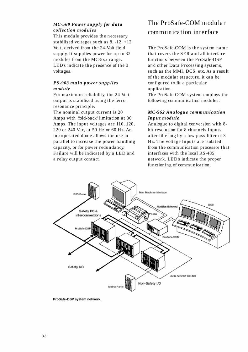
ProSafe-DSP system network.
33
MC-573 Data collection module
The module can collect data from
max.12 modules. The scan interval is 1
millisecond. Data changes are stored
with a time-stamp and communicated
to the ProSafe-COM system. LED’s
indicate the proper functioning of
communication with the local RS-485
n e t w o r k .
MC-576 Output driver module
Via the RS-485 local network, 12
pulse-train Outputs can be controlled
that create logic Inputs for the
P r o S a f e - D S P system. At the front
panel LED’s indicate the proper
functioning of communication.
MC-581 Digital input module
For interfacing additional DC signals,
this module converts 16 Inputs at 24
Volt for communication with the MC-
573 data collection module.
MC-582 Pulse-train input module
For interfacing 16 additional Pulse-
train signals, this module communi-
cates with the MC-573 data collection
m o d u l e .
MC-584 & MC-585 Parallel
i n t e r f a c e
The 32 discrete Outputs can be used to
present status information that
originate from the ProSafe-DSP
system, to external equipment such as
a DCS or SCADA system. The time-
resolution is 1-millisecond. The Inputs
for the MC-584 are maximum four (8-
bits) shift-registers from any other
D S P module. The MC-585 is the rail-
mounted termination connector that
contains 32 LED’s for status
i n d i c a t i o n .
CO-950 Basic Communication
m o d u l e
This communication processor is an
industrial PC, which consists of a 5
slots bus-board carrying standard PC
modules: CPU, dual ported COM ports
and a local network controller. The
CO-950 can be equipped with up to 4
serial ports (default 2) and runs the
standard or extended ModBus protocol
for status & event retrieval and
override commands. A fifth serial COM
port is used for configuration and
maintenance, or can be connected to
the optional LCD display & keyboard
CP-953. The ProSafe-DSP modules are
interrogated via a dedicated Local
Network.
Depending on the application
additional modules can be added. This
industrial PC hardware platform
supports the following (non-safety)
f u n c t i o n a l i t y :
•Presentation of the ProSafe-DSP
status to DCS and other equipment;
•Communication & scaling of the
analogue Inputs from ProSafe-DSP;
•Creating Inputs for overrides, etc., in
the ProSafe-DSP;
•Sequence of Event Recording;
•Time-stamp of the Events from the
P r o S a f e - D S P s y s t e m ;
•Synchronising the real-time with i.e.
DCF-77, GPS or other source;
•Presentation of diagnostic
i n f o r m a t i o n .
CS-951 Serial interface module
By adding this module to the CO-950
the total number of serial ports will be
f o u r.
CP-952 Printer interface module
A parallel printer port is provided by
this module.
CP-953 LCD & keyboard interface
m o d u l e
This module is meant to create access
to ProSafe-COM for the process
operator or maintenance engineer.
34
CE-954 Ethernet Controller module
The CE-954 will create an Ethernet
interface using either the TCP/IP o r
U D P / I P p r o t o c o l .
CN-955 Local-Network controller
m o d u l e
For large ProSafe-DSP systems or
redundant systems this module creates
a second Local-Network, that
interrogates the DSP m o d u l e s .
MI-983 & MO-986 Matrix-controller
input & output module
For interfacing with solid-state matrix-
panels these modules will monitor the
Inputs from push-buttons & key-
switches and create Outputs for signal
lamps. The communication with the
basic CO-950 is via the dedicated Local
Network. Proper operation is indicated
via LED’s on the front panel.
BR-987 & BR-988 Local-Network
r e p e a t e r s
The dedicated Local RS-485 Network
segment connects a maximum of 32
D S P modules and has a length that
may not exceed 300 meters. If more
segments are required, the BR-987 can
be used to create another isolated
segment. Up to five BR-987 may be
c a s c a d e d .
The BR-988 is a fibre-optic bus
repeater and is designed to extend the
Local-Network over a long distance of
maximum 3000-meter and has
redundant fibre-optic ST- c o n n e c t i o n s .
35
8 Glossary of terms
2 o o 3 : see at ‘TMR’.a v a i l a b i l i t y : The probability that a system iscapable to fulfil its function at some instant oftime. Practically it is often assumed to be constantand expressed in the ‘FTR’.cause & effect diagram: A matrix drawingshowing the functional process Safety interlocksbetween Inputs and Outputs of a Safety system.(See also at ‘FLD’).common-cause failures: Failures originatingfrom the same external or internal conditionscausing coincident failures of two or moreseparate channels in a redundancy system,leading to system failure. (See also at ‘systematicf a i l u r e s ’ ) .covert failure: A non-revealed defect in a systemthat is not detected by the incorporated testmechanisms. It will cause the system to fail to actp r o p e r l y, when a ‘demand’ for a process shutdowncomes from the Safety critical process parameters.demand: The excess of a process safety-parameter beyond the safety limit, necessitating atrip of the process by intervention of the SIS.d e m a n d - r a t e : The frequency of a process tripd e m a n d .diagnostic coverage factor: The percentage offailures detected by manual or automaticdiagnostic tests. It can be expressed in a factorthat is always smaller than 1 (i.e. C = 0.95). TheC-factor comprises the percentage of failures inmodules, software, external wiring, internalwiring, cables, interconnections and otherfunctions that are detected by the built-in testfunctions, or by a suitable test program.dangerous failure: A failure which has thepotential to put the safety-related system in adangerous or fail-to-function state.d e c i d e r : See at ‘voter’ .de-energised safe condition: In this context: theelectrical or pneumatic valves, which canshutdown the guarded process, are energisedduring the normal safe process situation. If anunsafe condition arises, the spring-loaded valvewill move to the safe position, because the energyis cut off. Larger valves are moved by releasingcompressed air by means of the electrically de-energised valve.demand: D C F - 7 7 : Accurate time signals broadcasted fromG e r m a n y, Frankfurt, with a range ofapproximately 1000 km. Comparable time signals,with different coding are available in the USA,Fort Collins and in the UK, Rugby.D C S : Distributed (or Digital) Control System. Aprocess control system based on computerintelligence and using a data-highway todistribute the different functions to specialisedc o n t r o l l e r s .dynamic logic circuit: In this context: the validlogic-state can only exist and perform logic control,if the circuit is activated continuously, usingalternating logic signals.Emergency Shutdown: Commonly usedterminology to refer to the safeguarding systems,that comprise the Safety interlocks and start-up ®ular shutdown sequences. The system isespecially suited to shutdown a plant in case of aprocess parameter limit-excess. These systems arealso referred to as Safety Related Systems (SRS),or SIS, which stands for a Safety InstrumentedS y s t e m .
E M I : Electrical-Magnetic Interference.E M C : Electrical-Magnetic Compatibilitye r r o r : A detected discrepancy between acomputed, observed or measured value orcondition and the true, specified or theoreticallycorrect value or condition. An error is that part ofthe system state, which is liable to lead to afailure. event: A change of state of Inputs or Outputs, aswell as intermediate logic status.f a i l - s a f e : The built-in capacity of a system suchthat predictable equipment failure modes onlycause system failures in which the system reachesand remains in a safe fall-back state. - A c o n t r o lsystem that, after one or multiple failures, goesinto a predetermined safe condition. f a i l u r e : Loss of function of a single component,system part, or of the entire system.f a u l t : An abnormal condition that may cause areduction in, or loss of, the capability of afunctional unit to perform a required function.f a u l t - a v o i d a n c e : The use of techniques andprocedures, which aim to avoid the introduction offaults during any phase of the safety systeml i f e c y c l e .f a u l t - t o l e r a n t : A system that continues to fullyperform its functions without interruption, inspite of component failures or errors.F M E A : Failure Mode and Effect A n a l y s i s .F L D : Functional Logic Diagram. A g r a p h i c a lrepresentation of the system functions, showingthe logic-gates and timers as well as the logicsignal interconnections.F P S O : Floating Production & Storage &O f f l o a d i n g .FTR: False Trip Rate. It equals 1/MTNF. A l s orefer to ‘Av a i l a b i l i t y ’ & ‘nuisance failure’.G P S : Global Positioning System with absolutetime-synchronisation capability.HIPPS & HIPS: High Integrity (Pressure)Protection System. Also called: ‘Over PressureProtection System’ o r’ O P P S ’ .host system: A computer such as a DCS, amainframe, workstation or PC that communicateswith the ProSafe-PLC via the serial interface.hot repair: Replacement of printed circuit boardsor modules in a fully functioning system, withoutaffecting the controlled process.I E C : International Electronic Committee.i n h e r e n t l y : Existing in something as a naturaland inseparable quality. (synonyms: inbred,inborn, internal, and ingrained.)inherently fail-safe: A particular designeddynamic logic principle that achieves the fail-safep r o p e r t y, from the principle itself and not fromadditional components or test circuits.intermittent fault: An error that occurs onlyoccasionally due to installed hardware, EMI,varying software status, or software bugs. A l s oreferred to as ‘soft-error’. See also under‘undetected failure’.L E D : Light Emitting Diode.M a g l o g : A former namefor the solid-state andinherently fail-safe technology, which employsmagnetic cores as logic-gate elements. Thistechnology is used in the ProSafe-DSP s y s t e m .M T T R : Mean Time To Repair. The mean timebetween the occurrence of a failure and the returnto normal failure-free operation after a correctiveaction. This time also includes the time requiredfor failure detection, failure search and re-startingthe system.
36
MMI: Man Machine Interface or ‘operatorinterface’, usually a computer screen to presentthe actual process and system status. It offers thepossibility for regular system interventions, datahandling and storage. nuisance failure: A failure arising out of anerroneous assessment of the situation. A s h u t d o w nis initiated, though no real impairment of Safetyexists. Also referred to as ‘false trip’.P C : Personal Computer.P E S : Programmable Electronic System. See alsoa t ’P L C ’ .P f d : The probability of a failure on demand, toshutdown the process coming from the Safetyparameters of the process. This parameter isdegrading during the mission time, test intervaltime. Therefore the average figure Pfd average isused in calculations.Phe: The Probability of a hazardous event equals:Phe = Pfd (average)x Demand-rate.P L C : Programmable Logic Controller. Also ‘PES’,meaning Programmable Electronic System. p r o o f - t e s t : A periodic test performed to detectfailures in a SIS so that, if necessary, the systemcan be restored to an ‘as new’ condition or as closeas practical to this condition. In practice, this isonly possible when the SIS system is disconnectedfrom the process.redundancy: Use of elements identical in design,construction and in function with the objective tomake the system more robust for self-revealingfailures. Sometimes referred to as ‘similarredundancy’, which is the opposite of ‘diverseredundancy’. It can apply to hardware as well asto software.r e l i a b i l i t y : The probability that no functionalfailure has occurred in a system during a givenperiod of time.revealed failure: A failure in a system that isdetected by the systems self-diagnostics.reverse-fault immune: The usage of specialdesign methods that are sometimes referred to asa ‘firewall’. This implies that any fault in aparticular system module cannot affect the safeoperation of the SIS. Also called ‘interference free’,or in German: ‘Rückwirkungsfrei’.safe failure: A failure which does not have thepotential to put the SIS in a dangerous or fail-to-function state.Safety: Freedom from unplanned adverse effectson the safe use, operation and maintenance of as y s t e m .safety integrity: The probability of a SISsatisfactorily performing the required safetyfunctions under all the stated conditions within astated period of time. See at ‘SIL’Safety interlocks: The functional relationshipbetween system Inputs and Outputs in theoperational mode of the plant. It is installationoriented, reflecting mechanical relationships. Inlogic terminology, the ‘and’ & ‘or’ gates representedby the Cause & Effect diagram (see also at ‘FLD’).s c a n - t i m e : The time required to execute thecomplete application program.S C A D A : Supervisory Control and DataA c q u i s i t i o n .SER: Sequence of Events Recorder, based on real-time state changes of events in the system (seealso at ‘event’).S I L: Safety Integrity Level as proposed by theIEC defining a Pfd by order of magnitude, whichis related to the risk (Pfd) involved in varioustypes of processes. In practice the SIL range isfrom 1 to 4 for most Industrial processes.
S I S : Safety Instrumented System. s o f t - e r r o r : See at ‘intermittent fault’.solid-state logic: An adjective used to describecircuits whose functionality depends uponelectronic components as semiconductors,resistors, capacitors, magnetic cores, etc. andwhich is not depending on any software.state-machine: Also called a ‘finite state-m a c h i n e ’ is used to build sequential logic circuits,that is are capable to execute a (small) controltask fully autonomously. The hardware ischaracterised by ‘present state’ and ‘next state’,with ‘conditional transitions’, opposing to thetechnology as found in traditional combinatorygate-logic, employed in conventionalm i c r o p r o c e s s o r s .systematic failures: A failure related in adeterministic way to a certain cause, which canonly be eliminated by a modification of the designor of the manufacturing process, operationalprocedures, documentation or other relevantf a c t o r s .T M R : Triple Modular Redundancy. A solution toachieve fault-tolerance by a 2 out of 3 votingconfiguration. Also referred to as 2oo3 voting. t r i p : A shutdown of the process by the Safetys y s t e m .T Ü V: Technische ‹eberwachungs Verein. A t e s t i n glaboratory in Germany that certifies Safety ofequipment, according the standards issued by theIEC, VDE and DIN. un-detected failure: A failure that impairs thesystem Safety, but remains un-detected. It isrelated to the risk (Pfd) involved in various typesof processes. This type of failures can accumulatein a Safety system, causing a degradation of theSafety performance (SIL), as a function of time.By definition redundancy and voting devices areno remedy for this type of un-safe failures. (seealso under ‘covert failure’.)v a l i d a t i o n : Confirmation by examination andprovision of objective evidence that the particularrequirements for a specific intended use aref u l f i l l e d .VDU: Video Display Unit.Ve r i f i c a t i o n : Confirmation by examination andprovision of objective evidence that therequirements have been fulfilled.VFC: Voltage Free Contact.Voter: In a redundant system configuration thisdecider hardware (and/or software) is applied tocompare the performance/results of modules andto make a selection based on fault-tolerance fordetected-faults. The structure of the voting devicewill determine whether this will improve thesafety and/or the availability of the system. (Seealso at: “un-detected failure’.)

37
The company
Founded in 1962, Yokogawa Industrial
Safety Systems is one of the world’s
most experienced Safety and Control
firms. Today Yokogawa ISS with its
headquarters in The Netherlands
provides services to clients on a global
scale.
Yokogawa ISS is a company on the
move, one that stays in touch with its
customers and remains at the forefront
of technology by co-operation with
technical universities and certifying
bodies. Further by active participation
in standardisation committees, that
are involved in the development of
international Safety standards we stay
abreast of the evolution of the
profession of Industrial Safeguarding.
Yokogawa ISS, as one of the four
‘Centres of Excellence’ within the
Yokogawa Corporation, we are
committed to offer protection systems
of the highest Safety Integrity Level
for the oil & gas, chemical process,
nuclear and conventional power
industries.
The Yokogawa ISS project organisation
operates on a world-wide basis and is
ISO9001 certified. The activities
comprise the realisation of turnkey
projects, after sales service and
technical customer training. Yo k o g a w a
remains at the forefront of technology
and the development of international
Safety standards by participation and
co-operation with technical
universities, standardisation
committees, certifying authorities and
inspection agencies.
Yokogawa ISS a subsidiary of
Yokogawa Electric Corporation is a
major player in the world of
Measurement, Control and Safety. The
company employs over 11000 people
world-wide and offers the financial
backing that will support continued
growth through strategic acquisitions
and products innovation.
The ProSafe-Family of products
The ProSafe Family of products is
capable of covering all functionality as
found in today’s Safety and Process
Control systems. Each ProSafe Family
member covers one or more specific
aspects of the total system
f u n c t i o n a l i t y. This ranges from the
High Integrity Protection Systems
HIPPS, ESD, PSD, and F&G systems,
up to the Man Machine Interface,
Distributed Control Systems and very
large supervisory ‘SCADA’ s y s t e m s .
By a policy of continuous innovation,
the ProSafe-Family of products will
remain up-to-date with the imminent
developments in International
Regulations and customer
requirements. The governing design
criteria remain the creation of superior
and comprehensive Safety system
solutions, at minimal ‘cost of
ownership’, prepared for a long useful
l i f e t i m e .
9 Yokogawa ISS serving Industrial Safety

38

39

40