Embed Size (px)
Citation preview
350 East Plumeria DriveSan Jose, CA 95134USA
July 2013202-11250-02
ProSAFE Fast Ethernet PoE Smart Switch FS728TLPHardware Instal lat ion Guide
2
ProSAFE Fast Ethernet PoE Smart Switch FS728TLP
SupportThank you for selecting NETGEAR products. After installing your device, locate the serial number on the label of your product and use it to register your product at https://my.netgear.com. You must register your product before you can use NETGEAR telephone support. NETGEAR recommends registering your product through the NETGEAR website. For product updates and web support, visit http://support.netgear.com.Phone (US & Canada only): 1-888-NETGEAR.Phone (Other Countries): Check the list of phone numbers at http://support.netgear.com/general/contact/default.aspx.
TrademarksNETGEAR, the NETGEAR logo, and Connect with Innovation are trademarks and/or registered trademarks of NETGEAR, Inc. and/or its subsidiaries in the United States and/or other countries. Information is subject to change without notice. © NETGEAR, Inc. All rights reserved.
Revision History
Publication Part Number
Publish Date Comments
202-11250-02 July 2013 • Made minor corrections and revisions• Added information about the product label• Replaced references to the Software Administration Manual with
references to the web management user guide
202-11250-01 June 2013 First publication
Contents
Chapter 1 Introduction and Hardware DescriptionOverview. . . . . . . . . . . . . . . . . . . . . . . . . . . . . . . . . . . . . . . . . . . . . . . . . . . . 5Switch Features . . . . . . . . . . . . . . . . . . . . . . . . . . . . . . . . . . . . . . . . . . . . . . 6Package Contents . . . . . . . . . . . . . . . . . . . . . . . . . . . . . . . . . . . . . . . . . . . . 8Front Panel . . . . . . . . . . . . . . . . . . . . . . . . . . . . . . . . . . . . . . . . . . . . . . . . . . 9Back Panel . . . . . . . . . . . . . . . . . . . . . . . . . . . . . . . . . . . . . . . . . . . . . . . . . 10LEDs. . . . . . . . . . . . . . . . . . . . . . . . . . . . . . . . . . . . . . . . . . . . . . . . . . . . . . 10Product Label . . . . . . . . . . . . . . . . . . . . . . . . . . . . . . . . . . . . . . . . . . . . . . . 11RJ-45 Ports. . . . . . . . . . . . . . . . . . . . . . . . . . . . . . . . . . . . . . . . . . . . . . . . . 12SFP GBIC Modules . . . . . . . . . . . . . . . . . . . . . . . . . . . . . . . . . . . . . . . . . . 12Factory Defaults Button and Reset Button . . . . . . . . . . . . . . . . . . . . . . . . .12
Chapter 2 InstallationStep 1: Prepare the Site . . . . . . . . . . . . . . . . . . . . . . . . . . . . . . . . . . . . . . . 14Step 2: Install the Switch . . . . . . . . . . . . . . . . . . . . . . . . . . . . . . . . . . . . . . 14
Install the Switch on a Flat Surface . . . . . . . . . . . . . . . . . . . . . . . . . . . .14Install the Switch in a Rack. . . . . . . . . . . . . . . . . . . . . . . . . . . . . . . . . . . 15
Step 3: Check the Installation. . . . . . . . . . . . . . . . . . . . . . . . . . . . . . . . . . . 16Step 4: Connect Devices to the Switch . . . . . . . . . . . . . . . . . . . . . . . . . . .16Step 5: Install an SFP GBIC Module . . . . . . . . . . . . . . . . . . . . . . . . . . . . .17Step 6: Apply AC Power . . . . . . . . . . . . . . . . . . . . . . . . . . . . . . . . . . . . . . . 17Step 7: Manage the Switch through a Web Browser or through the Smart Control Center . . . . . . . . . . . . . . . . . . . . . . . . . . . . . . .18
Chapter 3 TroubleshootingTroubleshooting Chart . . . . . . . . . . . . . . . . . . . . . . . . . . . . . . . . . . . . . . . . 20Troubleshooting Suggestions . . . . . . . . . . . . . . . . . . . . . . . . . . . . . . . . . . . 20
Network Adapter Cards . . . . . . . . . . . . . . . . . . . . . . . . . . . . . . . . . . . . . 20Configuration . . . . . . . . . . . . . . . . . . . . . . . . . . . . . . . . . . . . . . . . . . . . . 21Switch Integrity . . . . . . . . . . . . . . . . . . . . . . . . . . . . . . . . . . . . . . . . . . . . 21Autonegotiation. . . . . . . . . . . . . . . . . . . . . . . . . . . . . . . . . . . . . . . . . . . . 21
Appendix A Physical and Technical Specifications
3
1
1. Introduction and Hardware DescriptionThe NETGEAR® ProSAFE® Fast Ethernet PoE Smart Switch FS728TLP is a state-of-the-art, high-performance, IEEE-compliant network solution for users who require the flexibility of small form-factor pluggable (SFP) GBIC slots and the ease of Power over Ethernet (PoE). To simplify installation, the switch is shipped ready for use out of the box.
The chapter covers the following topics:
• Overview• Switch Features• Package Contents• Front Panel• Back Panel• LEDs• Product Label• RJ-45 Ports• SFP GBIC Modules• Factory Defaults Button and Reset Button
Note: For more information about the topics covered in this manual, visit the support website at support.netgear.com.
Note: Firmware updates with new features and bug fixes are made available from time to time on downloadcenter.netgear.com. Some products can regularly check the site and download new firmware, or you can check for and download new firmware manually. If the features or behavior of your product do not match what is described in this guide, you might need to update your firmware.
4
ProSAFE Fast Ethernet PoE Smart Switch FS728TLP
Overview
This hardware installation guide is for the NETGEAR ProSAFE Fast Ethernet PoE Smart Switch FS728TLP. The switch provides twenty-four 10/100BASE-T ports, four 10/100/1000BASE-T ports, two of which function as combo ports, and two small form-factor pluggable (SFP) GBIC slots, both of which function as combo ports. Power over Ethernet (PoE) is supported on ports 1 through 12.
You can make high-speed connections using the Gigabit Ethernet ports. For example:
• Connecting switches to each other with high-speed links• Connecting to a network backbone• Linking to high-speed servers• Providing 10/100/1000 Mbps copper and 100/1000 Mbps fiber connectivity
Note: In this guide, the NETGEAR ProSAFE Fast Ethernet PoE Smart Switch FS728TLP is referred as the switch.
The switch also provides the benefit of administrative management with a complete package of features to monitor, configure, and control the network. With the web management interface, you can view the switch’s many features and use them in a simple and intuitive manner. The switch’s management features include configuration for port and switch information, VLAN for traffic control, port trunking for increased bandwidth, and Class of Service (CoS) for traffic prioritization. Initial discovery of the switch on the network requires the Smart Control Center, a utility that runs on a computer.
You can use the switch freestanding or rack-mounted in a wiring closet or equipment room. The switch is IEEE-compliant and provides low latency for high-speed networking. All ports can automatically negotiate to the highest speed. This capability makes the switch well suited for environments that have a mix of Ethernet, Fast Ethernet, and Gigabit Ethernet devices. In addition, all RJ-45 ports operate in half- or full-duplex mode. The maximum segment length is 328 feet (100 meters) over a Category 5 twisted-pair cable.
You can use the switch as a desktop to build a small network that enables you to have 1000 Mbps access to a file server. With full duplex enabled, the switch port connected to the server or computer can provide 2000 Mbps throughput.
Introduction and Hardware Description
5
ProSAFE Fast Ethernet PoE Smart Switch FS728TLP
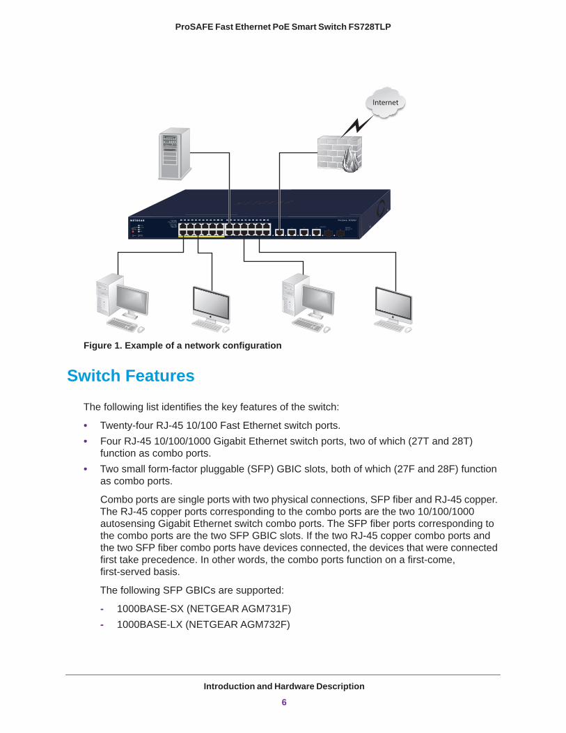
Figure 1. Example of a network configuration
Switch Features
The following list identifies the key features of the switch:
• Twenty-four RJ-45 10/100 Fast Ethernet switch ports.• Four RJ-45 10/100/1000 Gigabit Ethernet switch ports, two of which (27T and 28T)
function as combo ports.• Two small form-factor pluggable (SFP) GBIC slots, both of which (27F and 28F) function
as combo ports.
Combo ports are single ports with two physical connections, SFP fiber and RJ-45 copper. The RJ-45 copper ports corresponding to the combo ports are the two 10/100/1000 autosensing Gigabit Ethernet switch combo ports. The SFP fiber ports corresponding to the combo ports are the two SFP GBIC slots. If the two RJ-45 copper combo ports and the two SFP fiber combo ports have devices connected, the devices that were connected first take precedence. In other words, the combo ports function on a first-come, first-served basis.
The following SFP GBICs are supported:
- 1000BASE-SX (NETGEAR AGM731F)- 1000BASE-LX (NETGEAR AGM732F)
Introduction and Hardware Description
6
ProSAFE Fast Ethernet PoE Smart Switch FS728TLP
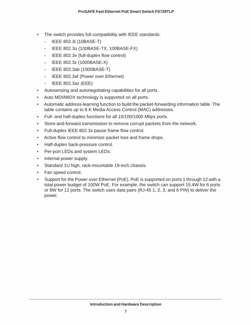
• The switch provides full compatibility with IEEE standards:- IEEE 802.3i (10BASE-T)- IEEE 802.3u (100BASE-TX, 100BASE-FX)- IEEE 802.3x (full-duplex flow control)- IEEE 802.3z (1000BASE-X)- IEEE 802.3ab (1000BASE-T)- IEEE 802.3af (Power over Ethernet)- IEEE 802.3az (EEE)
• Autosensing and autonegotiating capabilities for all ports.• Auto MDI/MIDX technology is supported on all ports. • Automatic address-learning function to build the packet-forwarding information table. The
table contains up to 8 K Media Access Control (MAC) addresses.• Full- and half-duplex functions for all 10/100/1000 Mbps ports.• Store-and-forward transmission to remove corrupt packets from the network.• Full-duplex IEEE 802.3x pause frame flow control.• Active flow control to minimize packet loss and frame drops.• Half-duplex back-pressure control.• Per-port LEDs and system LEDs.• Internal power supply.• Standard 1U high, rack-mountable 19-inch chassis.• Fan speed control.• Support for the Power over Ethernet (PoE). PoE is supported on ports 1 through 12 with a
total power budget of 100W PoE. For example, the switch can support 15.4W for 6 ports or 8W for 12 ports. The switch uses data pairs (RJ-45 1, 2, 3, and 6 PIN) to deliver the power.
Introduction and Hardware Description
7
ProSAFE Fast Ethernet PoE Smart Switch FS728TLP
Package Contents
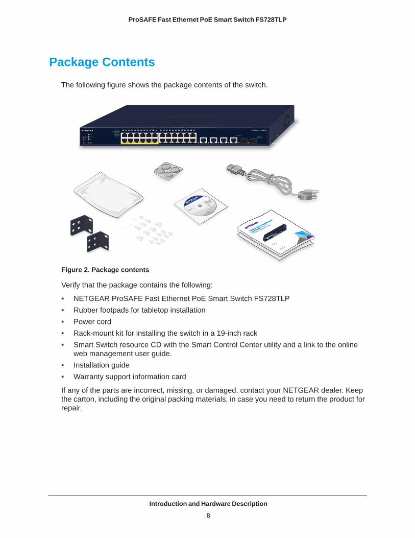
The following figure shows the package contents of the switch.
350 East Plumeria Drive
San Jose, CA 95134
USA
June 2013
202-11251-01
350 East Plumeria Drive
San Jose, CA 95134
USA
June 2013
202-11251-01
FS728T
LP
Figure 2. Package contents
Verify that the package contains the following:
• NETGEAR ProSAFE Fast Ethernet PoE Smart Switch FS728TLP• Rubber footpads for tabletop installation• Power cord• Rack-mount kit for installing the switch in a 19-inch rack• Smart Switch resource CD with the Smart Control Center utility and a link to the online
web management user guide.• Installation guide• Warranty support information card
If any of the parts are incorrect, missing, or damaged, contact your NETGEAR dealer. Keep the carton, including the original packing materials, in case you need to return the product for repair.
Introduction and Hardware Description
8
ProSAFE Fast Ethernet PoE Smart Switch FS728TLP
Front Panel
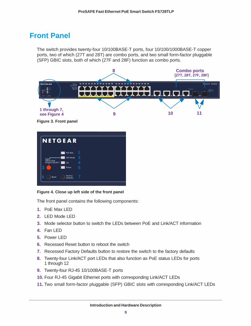
The switch provides twenty-four 10/100BASE-T ports, four 10/100/1000BASE-T copper ports, two of which (27T and 28T) are combo ports, and two small form-factor pluggable (SFP) GBIC slots, both of which (27F and 28F) function as combo ports.
1 through 7,see Figure 4
8
9 10 11
Combo ports[27T, 28T, 27F, 28F]
Figure 3. Front panel
12
345
6 7
Figure 4. Close up left side of the front panel
The front panel contains the following components:
1. PoE Max LED2. LED Mode LED3. Mode selector button to switch the LEDs between PoE and Link/ACT information4. Fan LED5. Power LED6. Recessed Reset button to reboot the switch7. Recessed Factory Defaults button to restore the switch to the factory defaults8. Twenty-four Link/ACT port LEDs that also function as PoE status LEDs for ports
1 through 129. Twenty-four RJ-45 10/100BASE-T ports10. Four RJ-45 Gigabit Ethernet ports with corresponding Link/ACT LEDs11. Two small form-factor pluggable (SFP) GBIC slots with corresponding Link/ACT LEDs
Introduction and Hardware Description
9
ProSAFE Fast Ethernet PoE Smart Switch FS728TLP
Back Panel
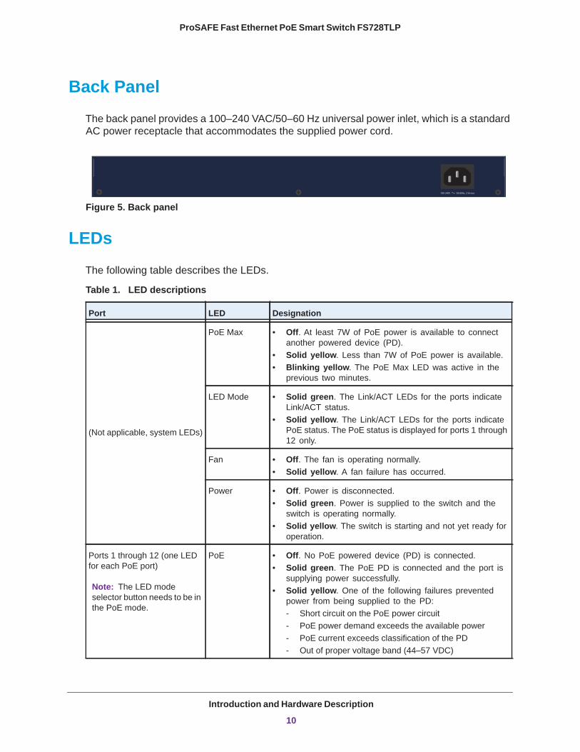
The back panel provides a 100–240 VAC/50–60 Hz universal power inlet, which is a standard AC power receptacle that accommodates the supplied power cord.
Figure 5. Back panel
LEDs
The following table describes the LEDs.
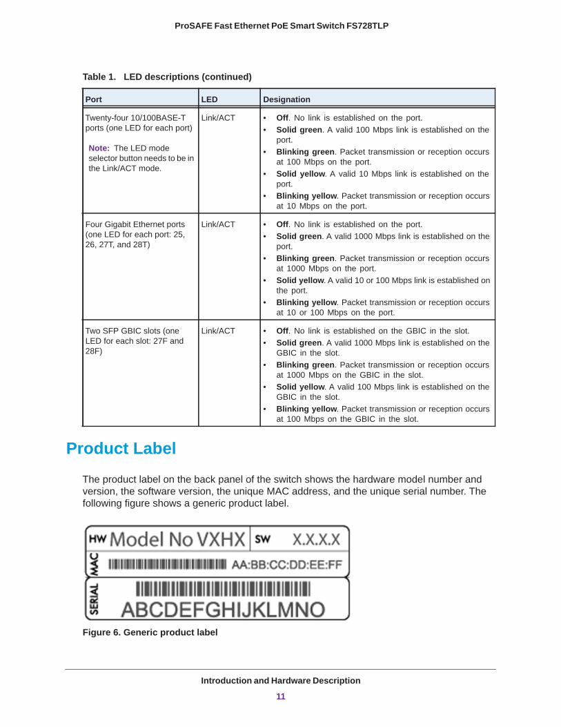
Table 1. LED descriptions
Port LED Designation
(Not applicable, system LEDs)
PoE Max • Off. At least 7W of PoE power is available to connect another powered device (PD).
• Solid yellow. Less than 7W of PoE power is available.• Blinking yellow. The PoE Max LED was active in the
previous two minutes.
LED Mode • Solid green. The Link/ACT LEDs for the ports indicate Link/ACT status.
• Solid yellow. The Link/ACT LEDs for the ports indicate PoE status. The PoE status is displayed for ports 1 through 12 only.
Fan • Off. The fan is operating normally.• Solid yellow. A fan failure has occurred.
Power • Off. Power is disconnected.• Solid green. Power is supplied to the switch and the
switch is operating normally.• Solid yellow. The switch is starting and not yet ready for
operation.
Ports 1 through 12 (one LED for each PoE port)
Note: The LED mode selector button needs to be in the PoE mode.
PoE • Off. No PoE powered device (PD) is connected.• Solid green. The PoE PD is connected and the port is
supplying power successfully.• Solid yellow. One of the following failures prevented
power from being supplied to the PD:- Short circuit on the PoE power circuit- PoE power demand exceeds the available power- PoE current exceeds classification of the PD- Out of proper voltage band (44–57 VDC)
Introduction and Hardware Description
10
ProSAFE Fast Ethernet PoE Smart Switch FS728TLP
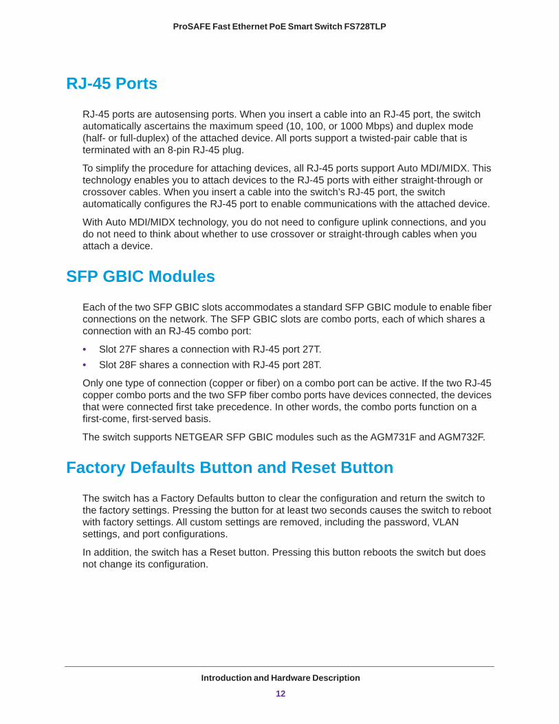
Product Label
The product label on the back panel of the switch shows the hardware model number and version, the software version, the unique MAC address, and the unique serial number. The following figure shows a generic product label.
Figure 6. Generic product label
Twenty-four 10/100BASE-T ports (one LED for each port)
Note: The LED mode selector button needs to be in the Link/ACT mode.
Link/ACT • Off. No link is established on the port.• Solid green. A valid 100 Mbps link is established on the
port.• Blinking green. Packet transmission or reception occurs
at 100 Mbps on the port.• Solid yellow. A valid 10 Mbps link is established on the
port.• Blinking yellow. Packet transmission or reception occurs
at 10 Mbps on the port.
Four Gigabit Ethernet ports (one LED for each port: 25, 26, 27T, and 28T)
Link/ACT • Off. No link is established on the port.• Solid green. A valid 1000 Mbps link is established on the
port.• Blinking green. Packet transmission or reception occurs
at 1000 Mbps on the port.• Solid yellow. A valid 10 or 100 Mbps link is established on
the port.• Blinking yellow. Packet transmission or reception occurs
at 10 or 100 Mbps on the port.
Two SFP GBIC slots (one LED for each slot: 27F and 28F)
Link/ACT • Off. No link is established on the GBIC in the slot.• Solid green. A valid 1000 Mbps link is established on the
GBIC in the slot.• Blinking green. Packet transmission or reception occurs
at 1000 Mbps on the GBIC in the slot.• Solid yellow. A valid 100 Mbps link is established on the
GBIC in the slot.• Blinking yellow. Packet transmission or reception occurs
at 100 Mbps on the GBIC in the slot.
Table 1. LED descriptions (continued)
Port LED Designation
Introduction and Hardware Description
11
ProSAFE Fast Ethernet PoE Smart Switch FS728TLP
RJ-45 Ports
RJ-45 ports are autosensing ports. When you insert a cable into an RJ-45 port, the switch automatically ascertains the maximum speed (10, 100, or 1000 Mbps) and duplex mode (half- or full-duplex) of the attached device. All ports support a twisted-pair cable that is terminated with an 8-pin RJ-45 plug.
To simplify the procedure for attaching devices, all RJ-45 ports support Auto MDI/MIDX. This technology enables you to attach devices to the RJ-45 ports with either straight-through or crossover cables. When you insert a cable into the switch’s RJ-45 port, the switch automatically configures the RJ-45 port to enable communications with the attached device.
With Auto MDI/MIDX technology, you do not need to configure uplink connections, and you do not need to think about whether to use crossover or straight-through cables when you attach a device.
SFP GBIC Modules
Each of the two SFP GBIC slots accommodates a standard SFP GBIC module to enable fiber connections on the network. The SFP GBIC slots are combo ports, each of which shares a connection with an RJ-45 combo port:
• Slot 27F shares a connection with RJ-45 port 27T.• Slot 28F shares a connection with RJ-45 port 28T.
Only one type of connection (copper or fiber) on a combo port can be active. If the two RJ-45 copper combo ports and the two SFP fiber combo ports have devices connected, the devices that were connected first take precedence. In other words, the combo ports function on a first-come, first-served basis.
The switch supports NETGEAR SFP GBIC modules such as the AGM731F and AGM732F.
Factory Defaults Button and Reset Button
The switch has a Factory Defaults button to clear the configuration and return the switch to the factory settings. Pressing the button for at least two seconds causes the switch to reboot with factory settings. All custom settings are removed, including the password, VLAN settings, and port configurations.
In addition, the switch has a Reset button. Pressing this button reboots the switch but does not change its configuration.
Introduction and Hardware Description
12
2
2. InstallationThis chapter describes how to install the switch, which involves the steps that are described in the following sections:
• Step 1: Prepare the Site• Step 2: Install the Switch• Step 3: Check the Installation• Step 4: Connect Devices to the Switch• Step 5: Install an SFP GBIC Module• Step 6: Apply AC Power• Step 7: Manage the Switch through a Web Browser or through the Smart Control Center
13
ProSAFE Fast Ethernet PoE Smart Switch FS728TLP
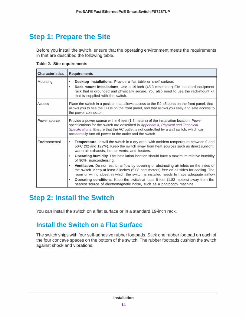
Step 1: Prepare the Site
Before you install the switch, ensure that the operating environment meets the requirements in that are described the following table.
Table 2. Site requirements
Characteristics Requirements
Mounting • Desktop installations. Provide a flat table or shelf surface.• Rack-mount installations. Use a 19-inch (48.3-centimeter) EIA standard equipment
rack that is grounded and physically secure. You also need to use the rack-mount kit that is supplied with the switch.
Access Place the switch in a position that allows access to the RJ-45 ports on the front panel, that allows you to see the LEDs on the front panel, and that allows you easy and safe access to the power connector.
Power source Provide a power source within 6 feet (1.8 meters) of the installation location. Power specifications for the switch are described in Appendix A, Physical and Technical Specifications. Ensure that the AC outlet is not controlled by a wall switch, which can accidentally turn off power to the outlet and the switch.
Environmental • Temperature. Install the switch in a dry area, with ambient temperature between 0 and 50ºC (32 and 122ºF). Keep the switch away from heat sources such as direct sunlight, warm-air exhausts, hot-air vents, and heaters.
• Operating humidity. The installation location should have a maximum relative humidity of 90%, noncondensing.
• Ventilation. Do not restrict airflow by covering or obstructing air inlets on the sides of the switch. Keep at least 2 inches (5.08 centimeters) free on all sides for cooling. The room or wiring closet in which the switch is installed needs to have adequate airflow.
• Operating conditions. Keep the switch at least 6 feet (1.83 meters) away from the nearest source of electromagnetic noise, such as a photocopy machine.
Step 2: Install the Switch
You can install the switch on a flat surface or in a standard 19-inch rack.
Install the Switch on a Flat SurfaceThe switch ships with four self-adhesive rubber footpads. Stick one rubber footpad on each of the four concave spaces on the bottom of the switch. The rubber footpads cushion the switch against shock and vibrations.
Installation
14
ProSAFE Fast Ethernet PoE Smart Switch FS728TLP
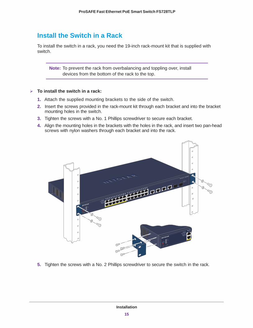
Install the Switch in a RackTo install the switch in a rack, you need the 19-inch rack-mount kit that is supplied with switch.
Note: To prevent the rack from overbalancing and toppling over, install devices from the bottom of the rack to the top.
To install the switch in a rack:
1. Attach the supplied mounting brackets to the side of the switch. 2. Insert the screws provided in the rack-mount kit through each bracket and into the bracket
mounting holes in the switch. 3. Tighten the screws with a No. 1 Phillips screwdriver to secure each bracket. 4. Align the mounting holes in the brackets with the holes in the rack, and insert two pan-head
screws with nylon washers through each bracket and into the rack.
5. Tighten the screws with a No. 2 Phillips screwdriver to secure the switch in the rack.
Installation
15
ProSAFE Fast Ethernet PoE Smart Switch FS728TLP
Step 3: Check the Installation
Before you apply power to the switch, do the following:
• Inspect the equipment thoroughly.• Verify that all cables are installed correctly.• Check cable routing to make sure that cables are not damaged or creating a safety
hazard.• Ensure that all equipment is mounted properly and securely.
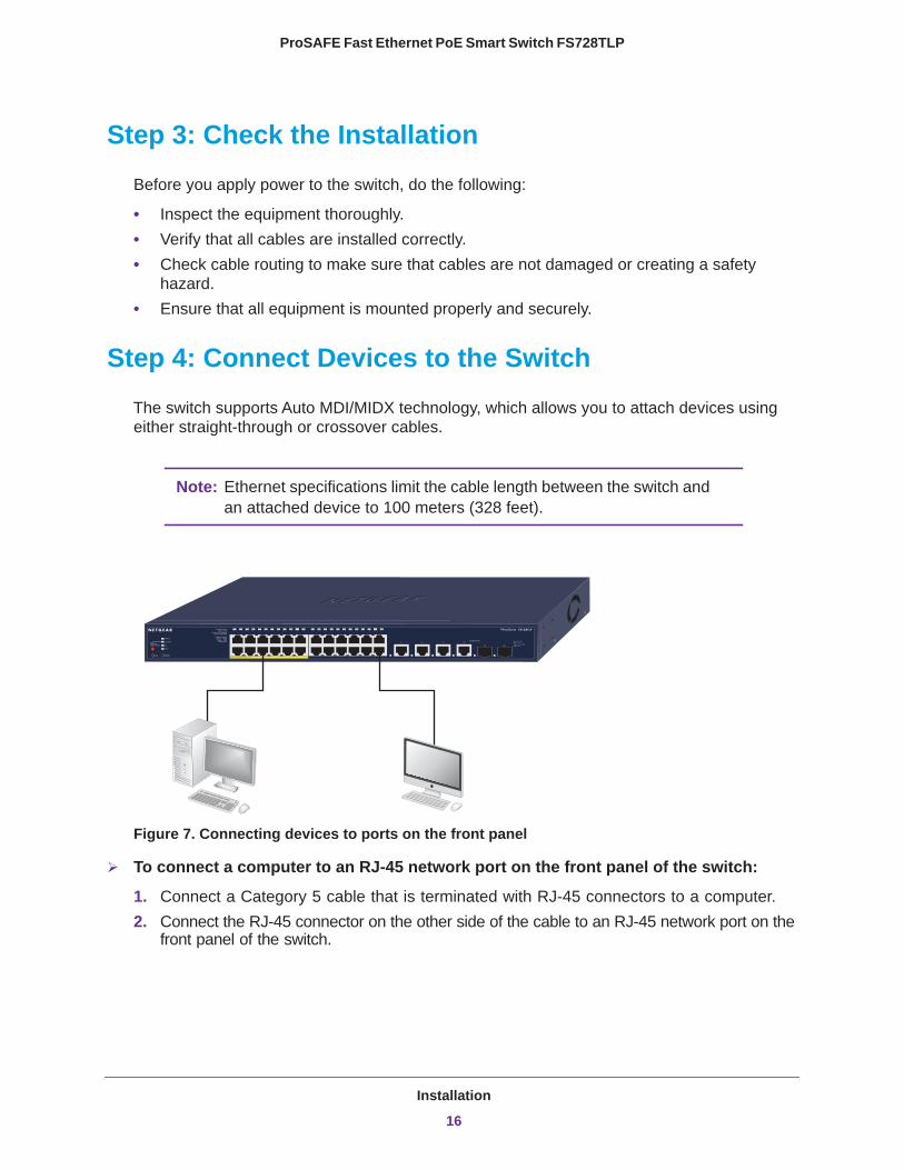
Step 4: Connect Devices to the Switch
The switch supports Auto MDI/MIDX technology, which allows you to attach devices using either straight-through or crossover cables.
Note: Ethernet specifications limit the cable length between the switch and an attached device to 100 meters (328 feet).
Figure 7. Connecting devices to ports on the front panel
To connect a computer to an RJ-45 network port on the front panel of the switch:
1. Connect a Category 5 cable that is terminated with RJ-45 connectors to a computer.2. Connect the RJ-45 connector on the other side of the cable to an RJ-45 network port on the
front panel of the switch.
Installation
16
ProSAFE Fast Ethernet PoE Smart Switch FS728TLP
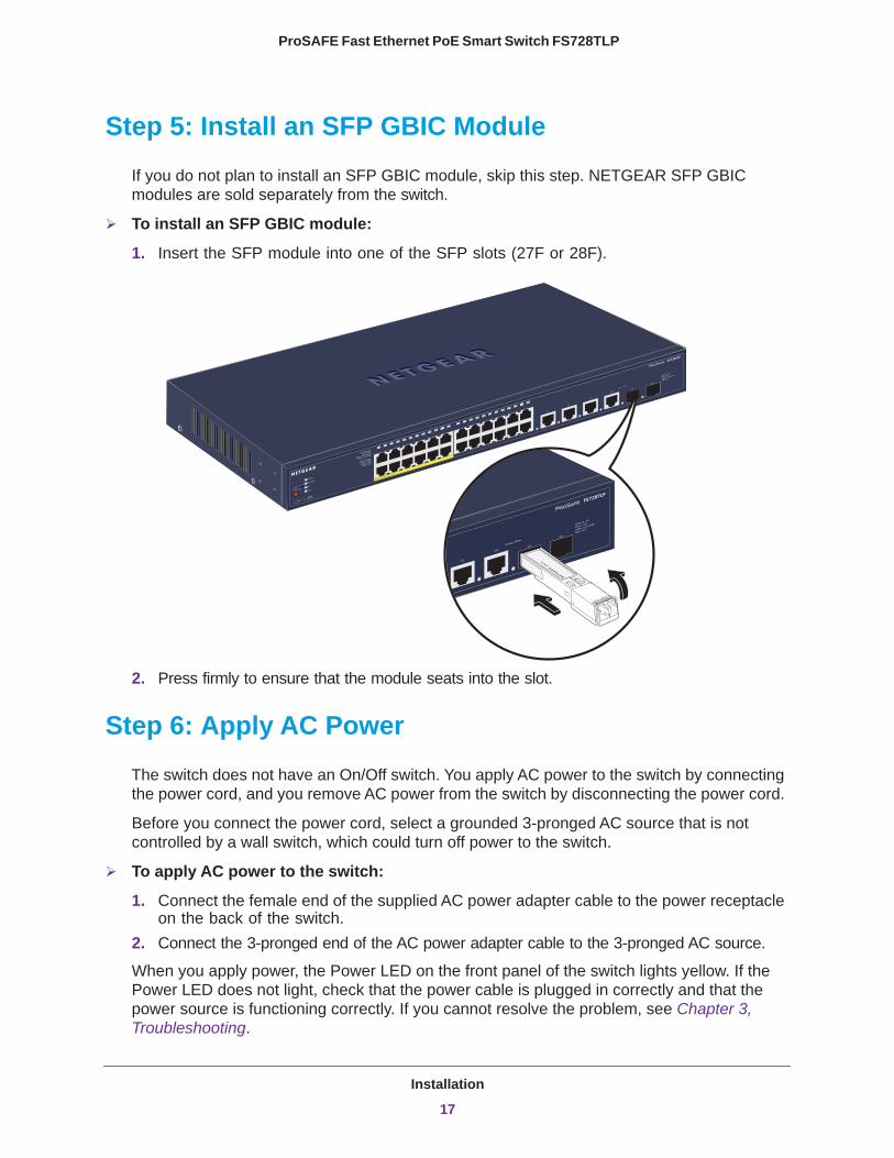
Step 5: Install an SFP GBIC Module
If you do not plan to install an SFP GBIC module, skip this step. NETGEAR SFP GBIC modules are sold separately from the switch.
To install an SFP GBIC module:
1. Insert the SFP module into one of the SFP slots (27F or 28F).
TxRx
2. Press firmly to ensure that the module seats into the slot.
Step 6: Apply AC Power
The switch does not have an On/Off switch. You apply AC power to the switch by connecting the power cord, and you remove AC power from the switch by disconnecting the power cord.
Before you connect the power cord, select a grounded 3-pronged AC source that is not controlled by a wall switch, which could turn off power to the switch.
To apply AC power to the switch:
1. Connect the female end of the supplied AC power adapter cable to the power receptacle on the back of the switch.
2. Connect the 3-pronged end of the AC power adapter cable to the 3-pronged AC source.
When you apply power, the Power LED on the front panel of the switch lights yellow. If the Power LED does not light, check that the power cable is plugged in correctly and that the power source is functioning correctly. If you cannot resolve the problem, see Chapter 3, Troubleshooting.
Installation
17
ProSAFE Fast Ethernet PoE Smart Switch FS728TLP
Step 7: Manage the Switch through a Web Browser or through the Smart Control Center
The switch contains management software that lets you view, change, and monitor the way the switch functions. The management software is not required for the switch to function. You can use the ports without using the management software. However, the management software lets you configure VLAN and trunking features, and lets you improve the efficiency of the switch, which results in the improvement of its overall performance as well as the performance of the network.
After you have powered the switch for the first time, you can configure and manage the switch by using either a web browser or the Smart Control Center utility. For information about configuring and managing the switch, see the web management user guide.
Note: If the switch cannot connect to a DHCP server, the switch uses 192.168.0.239 as its default IP address and 255.255.255.0 as its default subnet mask.
Note: To access the web management interface, enter password as the default password.
Installation
18
3
3. TroubleshootingThis chapter describes how you can troubleshoot the switch. The chapter covers the following topics:
• Troubleshooting Chart• Troubleshooting Suggestions
19
ProSAFE Fast Ethernet PoE Smart Switch FS728TLP
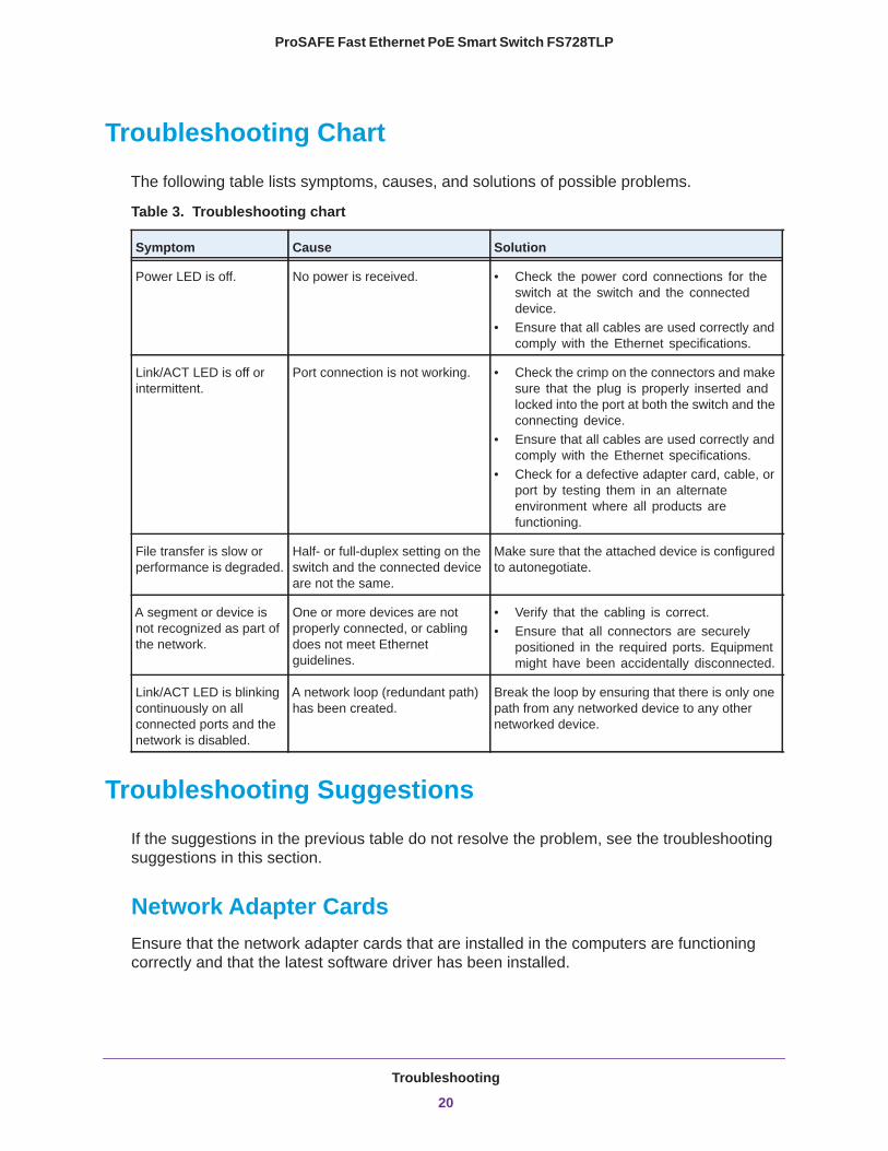
Troubleshooting Chart
The following table lists symptoms, causes, and solutions of possible problems.
Table 3. Troubleshooting chart
Symptom Cause Solution
Power LED is off. No power is received. • Check the power cord connections for the switch at the switch and the connected device.
• Ensure that all cables are used correctly and comply with the Ethernet specifications.
Link/ACT LED is off or intermittent.
Port connection is not working. • Check the crimp on the connectors and make sure that the plug is properly inserted and locked into the port at both the switch and the connecting device.
• Ensure that all cables are used correctly and comply with the Ethernet specifications.
• Check for a defective adapter card, cable, or port by testing them in an alternate environment where all products are functioning.
File transfer is slow or performance is degraded.
Half- or full-duplex setting on the switch and the connected device are not the same.
Make sure that the attached device is configured to autonegotiate.
A segment or device is not recognized as part of the network.
One or more devices are not properly connected, or cabling does not meet Ethernet guidelines.
• Verify that the cabling is correct. • Ensure that all connectors are securely
positioned in the required ports. Equipment might have been accidentally disconnected.
Link/ACT LED is blinking continuously on all connected ports and the network is disabled.
A network loop (redundant path) has been created.
Break the loop by ensuring that there is only one path from any networked device to any other networked device.
Troubleshooting Suggestions
If the suggestions in the previous table do not resolve the problem, see the troubleshooting suggestions in this section.
Network Adapter CardsEnsure that the network adapter cards that are installed in the computers are functioning correctly and that the latest software driver has been installed.
Troubleshooting
20
ProSAFE Fast Ethernet PoE Smart Switch FS728TLP
ConfigurationIf problems occur after you alter the network configuration, restore the original connections and determine the problem by implementing the new changes, one step at a time. Ensure that cable distances, repeater limits, and other physical aspects of the installation do not exceed the Ethernet limitations.
Switch IntegrityIf necessary, verify the integrity of the switch by resetting the switch. To reset the switch, disconnect the AC power from the switch and then reconnect the AC power. If the problem continues, contact NETGEAR technical support:
• Phone (US & Canada only): 1-888-NETGEAR.• Phone (Other Countries): Check the list of phone numbers at
http://support.netgear.com/general/contact/default.aspx.
AutonegotiationThe RJ-45 ports negotiate the correct duplex mode and speed if the device at the other end of the link supports autonegotiation. If the device does not support autonegotiation, the switch determines only the speed correctly, and the duplex mode defaults to half-duplex.
The Gigabit Ethernet ports negotiate speed, duplex mode, and flow control if the attached device supports autonegotiation.
Troubleshooting
21
A
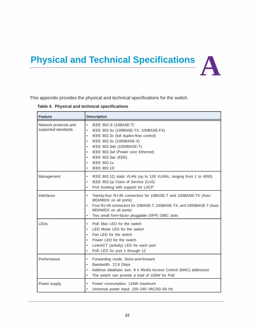
A. Physical and Technical SpecificationsThis appendix provides the physical and technical specifications for the switch.
Table 4. Physical and technical specifications
Feature Description
Network protocols and supported standards
• IEEE 802.3i (10BASE-T)• IEEE 802.3u (100BASE-TX, 100BASE-FX)• IEEE 802.3x (full duplex-flow control)• IEEE 802.3z (1000BASE-X)• IEEE 802.3ab (1000BASE-T)• IEEE 802.3af (Power over Ethernet)• IEEE 802.3az (EEE)• IEEE 802.1x• IEEE 802.1D
Management • IEEE 802.1Q static VLAN (up to 128 VLANs, ranging from 1 to 4093)• IEEE 802.1p Class of Service (CoS)• Port trunking with support for LACP
Interfaces • Twenty-four RJ-45 connectors for 10BASE-T and 100BASE-TX (Auto MDI/MIDX on all ports)
• Four RJ-45 connectors for 10BASE-T, 100BASE-TX, and 1000BASE-T (Auto MDI/MIDX on all ports)
• Two small form-factor pluggable (SFP) GBIC slots
LEDs • PoE Max LED for the switch• LED Mode LED for the switch• Fan LED for the switch• Power LED for the switch• Link/ACT (activity) LED for each port• PoE LED for port 1 through 12
Performance • Forwarding mode. Store-and-forward• Bandwidth. 12.8 Gbps• Address database size. 8 k Media Access Control (MAC) addresses• The switch can provide a total of 100W for PoE
Power supply • Power consumption. 124W maximum• Universal power input. 100–240 VAC/50–60 Hz
22
ProSAFE Fast Ethernet PoE Smart Switch FS728TLP
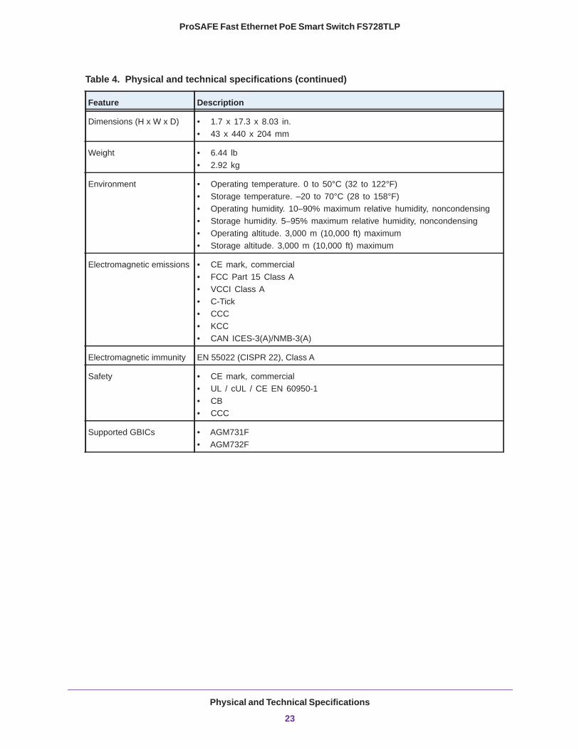
Dimensions (H x W x D) • 1.7 x 17.3 x 8.03 in.• 43 x 440 x 204 mm
Weight • 6.44 lb• 2.92 kg
Environment • Operating temperature. 0 to 50°C (32 to 122°F)• Storage temperature. –20 to 70°C (28 to 158°F)• Operating humidity. 10–90% maximum relative humidity, noncondensing• Storage humidity. 5–95% maximum relative humidity, noncondensing• Operating altitude. 3,000 m (10,000 ft) maximum• Storage altitude. 3,000 m (10,000 ft) maximum
Electromagnetic emissions • CE mark, commercial• FCC Part 15 Class A• VCCI Class A• C-Tick• CCC• KCC• CAN ICES-3(A)/NMB-3(A)
Electromagnetic immunity EN 55022 (CISPR 22), Class A
Safety • CE mark, commercial• UL / cUL / CE EN 60950-1• CB• CCC
Supported GBICs • AGM731F• AGM732F
Table 4. Physical and technical specifications (continued)
Feature Description
Physical and Technical Specifications
23