Embed Size (px)
Citation preview
350 East Plumeria DriveSan Jose, CA 95134USA
February 2013202-11166-021.0
ProSafe Managed SwitchCommand Line Inter face (CLI ) User Manual
10.0.1M7100-24XM4100-24G-POE+
M4100-26G
M4100-26-POEM4100-26G-POE
M4100-50G
M4100-50-POEM4100-50G-POE+
M4100-12GF
M4100-12G-POE+
M4100-D12GM4100-D10-POEM4100-D12G-POE+
ProSafe M4100 and M7100 Managed Switches
SupportThank you for selecting NETGEAR products. After installing your device, locate the serial number on the label of your product and use it to register your product at https://my.netgear.com. You must register your product before you can use NETGEAR telephone support. NETGEAR recommends registering your product through the NETGEAR website. For product updates and web support, visit http://support.netgear.com.Phone (US & Canada only): 1-888-NETGEAR.Phone (Other Countries): Check the list of phone numbers at http://support.netgear.com/general/contact/default.aspx.
TrademarksNETGEAR, the NETGEAR logo, and Connect with Innovation are trademarks and/or registered trademarks of NETGEAR, Inc. and/or its subsidiaries in the United States and/or other countries. Information is subject to change without notice. © NETGEAR, Inc. All rights reserved.
Revision History
Publication Part Number Version Publish Date Comments
202-11166-02 1.0 February 2013 Updated document.
202-11166-01 1.0 October 2012 First publication.
2
Contents
Chapter 1 Using the Command-Line InterfaceLicensing and Command Support . . . . . . . . . . . . . . . . . . . . . . . . . . . . . . . .8Command Syntax . . . . . . . . . . . . . . . . . . . . . . . . . . . . . . . . . . . . . . . . . . . . . 9Command Conventions . . . . . . . . . . . . . . . . . . . . . . . . . . . . . . . . . . . . . . . . 9Common Parameter Values . . . . . . . . . . . . . . . . . . . . . . . . . . . . . . . . . . . . 10Slot/Port Naming Convention . . . . . . . . . . . . . . . . . . . . . . . . . . . . . . . . . . . 11Using a Command’s “No” Form . . . . . . . . . . . . . . . . . . . . . . . . . . . . . . . . .12Managed Switch Modules . . . . . . . . . . . . . . . . . . . . . . . . . . . . . . . . . . . . . 12Command Modes . . . . . . . . . . . . . . . . . . . . . . . . . . . . . . . . . . . . . . . . . . . . 12Command Completion and Abbreviation . . . . . . . . . . . . . . . . . . . . . . . . . .16CLI Error Messages . . . . . . . . . . . . . . . . . . . . . . . . . . . . . . . . . . . . . . . . . . 16CLI Line-Editing Conventions . . . . . . . . . . . . . . . . . . . . . . . . . . . . . . . . . . . 17Using CLI Help . . . . . . . . . . . . . . . . . . . . . . . . . . . . . . . . . . . . . . . . . . . . . . 17Accessing the CLI. . . . . . . . . . . . . . . . . . . . . . . . . . . . . . . . . . . . . . . . . . . . 18
Chapter 2 Switching CommandsPort Configuration Commands . . . . . . . . . . . . . . . . . . . . . . . . . . . . . . . . . . 21Loopback Interface Commands . . . . . . . . . . . . . . . . . . . . . . . . . . . . . . . . .27Spanning Tree Protocol (STP) Commands . . . . . . . . . . . . . . . . . . . . . . . .30VLAN Commands. . . . . . . . . . . . . . . . . . . . . . . . . . . . . . . . . . . . . . . . . . . . 47Double VLAN Commands . . . . . . . . . . . . . . . . . . . . . . . . . . . . . . . . . . . . . 60Voice VLAN Commands. . . . . . . . . . . . . . . . . . . . . . . . . . . . . . . . . . . . . . . 63Provisioning (IEEE 802.1p) Commands . . . . . . . . . . . . . . . . . . . . . . . . . . .65Protected Ports Commands . . . . . . . . . . . . . . . . . . . . . . . . . . . . . . . . . . . . 65Private VLAN . . . . . . . . . . . . . . . . . . . . . . . . . . . . . . . . . . . . . . . . . . . . . . . 68GARP Commands . . . . . . . . . . . . . . . . . . . . . . . . . . . . . . . . . . . . . . . . . . . 71GVRP Commands . . . . . . . . . . . . . . . . . . . . . . . . . . . . . . . . . . . . . . . . . . . 73GMRP Commands . . . . . . . . . . . . . . . . . . . . . . . . . . . . . . . . . . . . . . . . . . . 75Port-Based Network Access Control Commands. . . . . . . . . . . . . . . . . . . .77802.1X Supplicant Commands. . . . . . . . . . . . . . . . . . . . . . . . . . . . . . . . . . 91Storm-Control Commands . . . . . . . . . . . . . . . . . . . . . . . . . . . . . . . . . . . . . 94Flow Control Commands . . . . . . . . . . . . . . . . . . . . . . . . . . . . . . . . . . . . . 104Port-Channel/LAG (802.3ad) Commands . . . . . . . . . . . . . . . . . . . . . . . .105Port Mirroring . . . . . . . . . . . . . . . . . . . . . . . . . . . . . . . . . . . . . . . . . . . . . . 121Static MAC Filtering . . . . . . . . . . . . . . . . . . . . . . . . . . . . . . . . . . . . . . . . . 123DHCP L2 Relay Agent Commands . . . . . . . . . . . . . . . . . . . . . . . . . . . . .127DHCP Client Commands . . . . . . . . . . . . . . . . . . . . . . . . . . . . . . . . . . . . . 131DHCP Snooping Configuration Commands . . . . . . . . . . . . . . . . . . . . . . .132Dynamic ARP Inspection Commands . . . . . . . . . . . . . . . . . . . . . . . . . . .141
3
ProSafe M4100 and M7100 Managed Switches
IGMP Snooping Configuration Commands . . . . . . . . . . . . . . . . . . . . . . . 148IGMP Snooping Querier Commands . . . . . . . . . . . . . . . . . . . . . . . . . . . . 157MLD Snooping Commands . . . . . . . . . . . . . . . . . . . . . . . . . . . . . . . . . . . 161MLD Snooping Querier Commands . . . . . . . . . . . . . . . . . . . . . . . . . . . . . 168
set mld querier . . . . . . . . . . . . . . . . . . . . . . . . . . . . . . . . . . . . . . . . . . . 168set mld querier query_interval . . . . . . . . . . . . . . . . . . . . . . . . . . . . . . . 169set mld querier timer expiry . . . . . . . . . . . . . . . . . . . . . . . . . . . . . . . . . 169set mld querier election participate. . . . . . . . . . . . . . . . . . . . . . . . . . . . 170show mldsnooping querier . . . . . . . . . . . . . . . . . . . . . . . . . . . . . . . . . . 170
Port Security Commands . . . . . . . . . . . . . . . . . . . . . . . . . . . . . . . . . . . . . 171LLDP (802.1AB) Commands . . . . . . . . . . . . . . . . . . . . . . . . . . . . . . . . . . 175LLDP-MED Commands . . . . . . . . . . . . . . . . . . . . . . . . . . . . . . . . . . . . . . 184Denial of Service Commands. . . . . . . . . . . . . . . . . . . . . . . . . . . . . . . . . . 193MAC Database Commands . . . . . . . . . . . . . . . . . . . . . . . . . . . . . . . . . . . 203ISDP Commands . . . . . . . . . . . . . . . . . . . . . . . . . . . . . . . . . . . . . . . . . . . 205Priority-Based Flow Control Commands . . . . . . . . . . . . . . . . . . . . . . . . . 210
Chapter 3 Multicast VLAN Registration (MVR)About MVR . . . . . . . . . . . . . . . . . . . . . . . . . . . . . . . . . . . . . . . . . . . . . . . . 214MVR Commands . . . . . . . . . . . . . . . . . . . . . . . . . . . . . . . . . . . . . . . . . . . 214
Chapter 4 Routing CommandsAddress Resolution Protocol (ARP) Commands . . . . . . . . . . . . . . . . . . . 222IP Routing Commands . . . . . . . . . . . . . . . . . . . . . . . . . . . . . . . . . . . . . . . 227Router Discovery Protocol Commands . . . . . . . . . . . . . . . . . . . . . . . . . . 244Virtual LAN Routing Commands . . . . . . . . . . . . . . . . . . . . . . . . . . . . . . . 248Virtual Router Redundancy Protocol Commands. . . . . . . . . . . . . . . . . . . 249DHCP and BOOTP Relay Commands . . . . . . . . . . . . . . . . . . . . . . . . . . . 257IP Helper Commands . . . . . . . . . . . . . . . . . . . . . . . . . . . . . . . . . . . . . . . . 259Open Shortest Path First (OSPF) Commands . . . . . . . . . . . . . . . . . . . . . 263OSPF Graceful Restart Commands . . . . . . . . . . . . . . . . . . . . . . . . . . . . . 304
nsf. . . . . . . . . . . . . . . . . . . . . . . . . . . . . . . . . . . . . . . . . . . . . . . . . . . . . 305nsf restart-interval. . . . . . . . . . . . . . . . . . . . . . . . . . . . . . . . . . . . . . . . . 305nsf helper . . . . . . . . . . . . . . . . . . . . . . . . . . . . . . . . . . . . . . . . . . . . . . . 306nsf helper disable . . . . . . . . . . . . . . . . . . . . . . . . . . . . . . . . . . . . . . . . . 307nsf [ietf] helper strict-lsa-checking . . . . . . . . . . . . . . . . . . . . . . . . . . . . 307
OSPF Interface Flap Dampening Commands . . . . . . . . . . . . . . . . . . . . . 309Routing Information Protocol (RIP) Commands . . . . . . . . . . . . . . . . . . . . 311ICMP Throttling Commands . . . . . . . . . . . . . . . . . . . . . . . . . . . . . . . . . . . 318
Chapter 5 IP Multicast CommandsMulticast Commands . . . . . . . . . . . . . . . . . . . . . . . . . . . . . . . . . . . . . . . . 321DVMRP Commands . . . . . . . . . . . . . . . . . . . . . . . . . . . . . . . . . . . . . . . . . 326PIM Commands . . . . . . . . . . . . . . . . . . . . . . . . . . . . . . . . . . . . . . . . . . . . 331Internet Group Message Protocol (IGMP) Commands . . . . . . . . . . . . . . 342IGMP Proxy Commands. . . . . . . . . . . . . . . . . . . . . . . . . . . . . . . . . . . . . . 349
4
ProSafe M4100 and M7100 Managed Switches
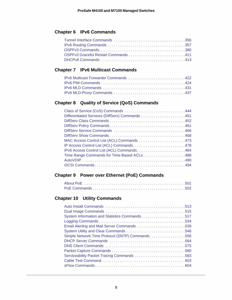
Chapter 6 IPv6 CommandsTunnel Interface Commands . . . . . . . . . . . . . . . . . . . . . . . . . . . . . . . . . .356IPv6 Routing Commands . . . . . . . . . . . . . . . . . . . . . . . . . . . . . . . . . . . . .357OSPFv3 Commands. . . . . . . . . . . . . . . . . . . . . . . . . . . . . . . . . . . . . . . . .380OSPFv3 Graceful Restart Commands . . . . . . . . . . . . . . . . . . . . . . . . . . .411DHCPv6 Commands . . . . . . . . . . . . . . . . . . . . . . . . . . . . . . . . . . . . . . . .413
Chapter 7 IPv6 Multicast CommandsIPv6 Multicast Forwarder Commands . . . . . . . . . . . . . . . . . . . . . . . . . . .422IPv6 PIM Commands . . . . . . . . . . . . . . . . . . . . . . . . . . . . . . . . . . . . . . . .424IPv6 MLD Commands . . . . . . . . . . . . . . . . . . . . . . . . . . . . . . . . . . . . . . .431IPv6 MLD-Proxy Commands . . . . . . . . . . . . . . . . . . . . . . . . . . . . . . . . . .437
Chapter 8 Quality of Service (QoS) CommandsClass of Service (CoS) Commands . . . . . . . . . . . . . . . . . . . . . . . . . . . . .444Differentiated Services (DiffServ) Commands . . . . . . . . . . . . . . . . . . . . .451DiffServ Class Commands . . . . . . . . . . . . . . . . . . . . . . . . . . . . . . . . . . . .452DiffServ Policy Commands. . . . . . . . . . . . . . . . . . . . . . . . . . . . . . . . . . . .461DiffServ Service Commands . . . . . . . . . . . . . . . . . . . . . . . . . . . . . . . . . .466DiffServ Show Commands . . . . . . . . . . . . . . . . . . . . . . . . . . . . . . . . . . . .468MAC Access Control List (ACL) Commands . . . . . . . . . . . . . . . . . . . . . .473IP Access Control List (ACL) Commands. . . . . . . . . . . . . . . . . . . . . . . . .478IPv6 Access Control List (ACL) Commands. . . . . . . . . . . . . . . . . . . . . . .484Time Range Commands for Time-Based ACLs . . . . . . . . . . . . . . . . . . . .488AutoVOIP . . . . . . . . . . . . . . . . . . . . . . . . . . . . . . . . . . . . . . . . . . . . . . . . .490iSCSI Commands . . . . . . . . . . . . . . . . . . . . . . . . . . . . . . . . . . . . . . . . . . .494
Chapter 9 Power over Ethernet (PoE) CommandsAbout PoE . . . . . . . . . . . . . . . . . . . . . . . . . . . . . . . . . . . . . . . . . . . . . . . .501PoE Commands . . . . . . . . . . . . . . . . . . . . . . . . . . . . . . . . . . . . . . . . . . . .502
Chapter 10 Utility CommandsAuto Install Commands . . . . . . . . . . . . . . . . . . . . . . . . . . . . . . . . . . . . . .513Dual Image Commands . . . . . . . . . . . . . . . . . . . . . . . . . . . . . . . . . . . . . .515System Information and Statistics Commands. . . . . . . . . . . . . . . . . . . . .517Logging Commands . . . . . . . . . . . . . . . . . . . . . . . . . . . . . . . . . . . . . . . . .534Email Alerting and Mail Server Commands . . . . . . . . . . . . . . . . . . . . . . .539System Utility and Clear Commands . . . . . . . . . . . . . . . . . . . . . . . . . . . .546Simple Network Time Protocol (SNTP) Commands. . . . . . . . . . . . . . . . .556DHCP Server Commands . . . . . . . . . . . . . . . . . . . . . . . . . . . . . . . . . . . .564DNS Client Commands . . . . . . . . . . . . . . . . . . . . . . . . . . . . . . . . . . . . . .575Packet Capture Commands . . . . . . . . . . . . . . . . . . . . . . . . . . . . . . . . . . .580Serviceability Packet Tracing Commands . . . . . . . . . . . . . . . . . . . . . . . .583Cable Test Command. . . . . . . . . . . . . . . . . . . . . . . . . . . . . . . . . . . . . . . .603sFlow Commands. . . . . . . . . . . . . . . . . . . . . . . . . . . . . . . . . . . . . . . . . . .604
5
ProSafe M4100 and M7100 Managed Switches
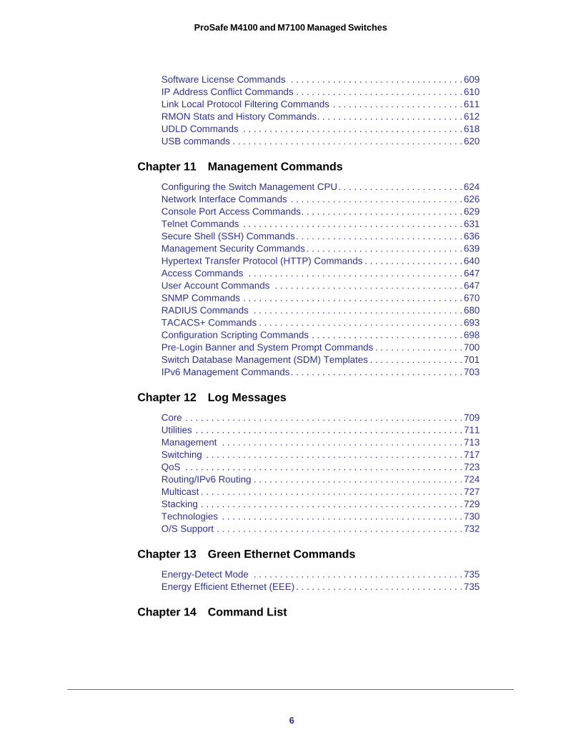
Software License Commands . . . . . . . . . . . . . . . . . . . . . . . . . . . . . . . . . 609IP Address Conflict Commands . . . . . . . . . . . . . . . . . . . . . . . . . . . . . . . . 610Link Local Protocol Filtering Commands . . . . . . . . . . . . . . . . . . . . . . . . . 611RMON Stats and History Commands. . . . . . . . . . . . . . . . . . . . . . . . . . . . 612UDLD Commands . . . . . . . . . . . . . . . . . . . . . . . . . . . . . . . . . . . . . . . . . . 618USB commands . . . . . . . . . . . . . . . . . . . . . . . . . . . . . . . . . . . . . . . . . . . . 620
Chapter 11 Management CommandsConfiguring the Switch Management CPU. . . . . . . . . . . . . . . . . . . . . . . . 624Network Interface Commands . . . . . . . . . . . . . . . . . . . . . . . . . . . . . . . . . 626Console Port Access Commands. . . . . . . . . . . . . . . . . . . . . . . . . . . . . . . 629Telnet Commands . . . . . . . . . . . . . . . . . . . . . . . . . . . . . . . . . . . . . . . . . . 631Secure Shell (SSH) Commands. . . . . . . . . . . . . . . . . . . . . . . . . . . . . . . . 636Management Security Commands . . . . . . . . . . . . . . . . . . . . . . . . . . . . . . 639Hypertext Transfer Protocol (HTTP) Commands . . . . . . . . . . . . . . . . . . . 640Access Commands . . . . . . . . . . . . . . . . . . . . . . . . . . . . . . . . . . . . . . . . . 647User Account Commands . . . . . . . . . . . . . . . . . . . . . . . . . . . . . . . . . . . . 647SNMP Commands . . . . . . . . . . . . . . . . . . . . . . . . . . . . . . . . . . . . . . . . . . 670RADIUS Commands . . . . . . . . . . . . . . . . . . . . . . . . . . . . . . . . . . . . . . . . 680TACACS+ Commands . . . . . . . . . . . . . . . . . . . . . . . . . . . . . . . . . . . . . . . 693Configuration Scripting Commands . . . . . . . . . . . . . . . . . . . . . . . . . . . . . 698Pre-Login Banner and System Prompt Commands . . . . . . . . . . . . . . . . . 700Switch Database Management (SDM) Templates . . . . . . . . . . . . . . . . . . 701IPv6 Management Commands. . . . . . . . . . . . . . . . . . . . . . . . . . . . . . . . . 703
Chapter 12 Log MessagesCore . . . . . . . . . . . . . . . . . . . . . . . . . . . . . . . . . . . . . . . . . . . . . . . . . . . . . 709Utilities . . . . . . . . . . . . . . . . . . . . . . . . . . . . . . . . . . . . . . . . . . . . . . . . . . . 711Management . . . . . . . . . . . . . . . . . . . . . . . . . . . . . . . . . . . . . . . . . . . . . . 713Switching . . . . . . . . . . . . . . . . . . . . . . . . . . . . . . . . . . . . . . . . . . . . . . . . . 717QoS . . . . . . . . . . . . . . . . . . . . . . . . . . . . . . . . . . . . . . . . . . . . . . . . . . . . . 723Routing/IPv6 Routing . . . . . . . . . . . . . . . . . . . . . . . . . . . . . . . . . . . . . . . . 724Multicast . . . . . . . . . . . . . . . . . . . . . . . . . . . . . . . . . . . . . . . . . . . . . . . . . . 727Stacking . . . . . . . . . . . . . . . . . . . . . . . . . . . . . . . . . . . . . . . . . . . . . . . . . . 729Technologies . . . . . . . . . . . . . . . . . . . . . . . . . . . . . . . . . . . . . . . . . . . . . . 730O/S Support . . . . . . . . . . . . . . . . . . . . . . . . . . . . . . . . . . . . . . . . . . . . . . . 732
Chapter 13 Green Ethernet CommandsEnergy-Detect Mode . . . . . . . . . . . . . . . . . . . . . . . . . . . . . . . . . . . . . . . . 735Energy Efficient Ethernet (EEE) . . . . . . . . . . . . . . . . . . . . . . . . . . . . . . . . 735
Chapter 14 Command List
6
1
1. Using the Command-Line InterfaceThe command-line interface (CLI) is a text-based way to manage and monitor the system. You can access the CLI by using a direct serial connection or by using a remote logical connection with telnet or SSH.
This chapter describes the CLI syntax, conventions, and modes. It contains the following sections:
• Licensing and Command Support • Command Syntax • Command Conventions • Common Parameter Values • Slot/Port Naming Convention • Using a Command’s “No” Form • Managed Switch Modules • Command Modes • Command Completion and Abbreviation • CLI Error Messages • CLI Line-Editing Conventions • Using CLI Help • Accessing the CLI
7
ProSafe M4100 and M7100 Managed Switches
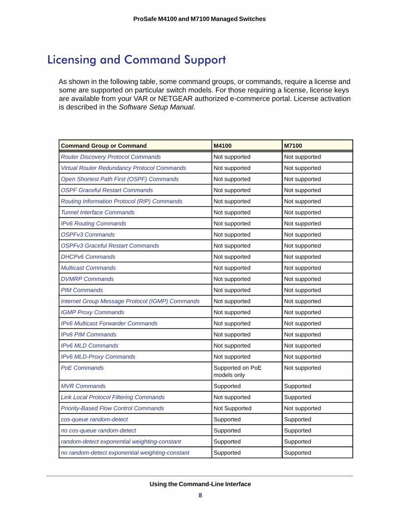
Licensing and Command Support
As shown in the following table, some command groups, or commands, require a license and some are supported on particular switch models. For those requiring a license, license keys are available from your VAR or NETGEAR authorized e-commerce portal. License activation is described in the Software Setup Manual.
Command Group or Command M4100 M7100
Router Discovery Protocol Commands Not supported Not supported
Virtual Router Redundancy Protocol Commands Not supported Not supported
Open Shortest Path First (OSPF) Commands Not supported Not supported
OSPF Graceful Restart Commands Not supported Not supported
Routing Information Protocol (RIP) Commands Not supported Not supported
Tunnel Interface Commands Not supported Not supported
IPv6 Routing Commands Not supported Not supported
OSPFv3 Commands Not supported Not supported
OSPFv3 Graceful Restart Commands Not supported Not supported
DHCPv6 Commands Not supported Not supported
Multicast Commands Not supported Not supported
DVMRP Commands Not supported Not supported
PIM Commands Not supported Not supported
Internet Group Message Protocol (IGMP) Commands Not supported Not supported
IGMP Proxy Commands Not supported Not supported
IPv6 Multicast Forwarder Commands Not supported Not supported
IPv6 PIM Commands Not supported Not supported
IPv6 MLD Commands Not supported Not supported
IPv6 MLD-Proxy Commands Not supported Not supported
PoE Commands Supported on PoE models only
Not supported
MVR Commands Supported Supported
Link Local Protocol Filtering Commands Not supported Supported
Priority-Based Flow Control Commands Not Supported Not supported
cos-queue random-detect Supported Supported
no cos-queue random-detect Supported Supported
random-detect exponential weighting-constant Supported Supported
no random-detect exponential weighting-constant Supported Supported
Using the Command-Line Interface
8
ProSafe M4100 and M7100 Managed Switches
Command Syntax
A command is one or more words that might be followed by one or more parameters. Parameters can be required or optional values.
Some commands, such as show network or clear vlan, do not require parameters. Other commands, such as network parms, require that you supply a value after the command. You must type the parameter values in a specific order, and optional parameters follow required parameters. The following example describes the network parms command syntax:
• network parms is the command name. • <ipaddr> and <netmask> are parameters and represent required values that you
must enter after you type the command keywords.• [gateway] is an optional parameter, so you are not required to enter a value in place of
the parameter.
The New Template User Manual lists each command by the command name and provides a brief description of the command. Each command reference also contains the following information:
• Format shows the command keywords and the required and optional parameters.• Mode identifies the command mode you must be in to access the command.• Default shows the default value, if any, of a configurable setting on the device.
The show commands also contain a description of the information that the command shows.
Command Conventions
In this document, the command name is in bold font. Parameters are in italic font. You must replace the parameter name with an appropriate value, which might be a name or number. Parameters are order-dependent.
random-detect queue-parms Supported Supported
no random-detect queue-parms Supported Supported
Format network parms <ipaddr> <netmask> [gateway]
Command Group or Command M4100 M7100
Using the Command-Line Interface
9
ProSafe M4100 and M7100 Managed Switches
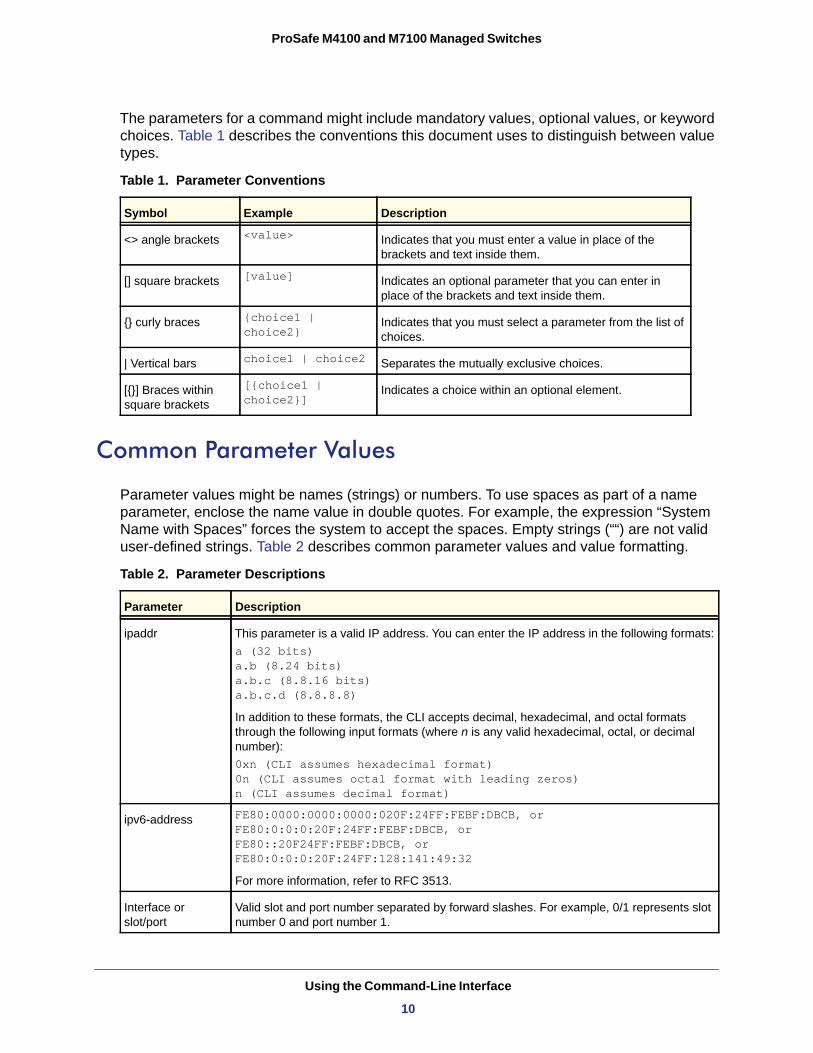
The parameters for a command might include mandatory values, optional values, or keyword choices. Table 1 describes the conventions this document uses to distinguish between value types.
Table 1. Parameter Conventions
<value>
[value]
{choice1 | choice2}
choice1 | choice2
[{choice1 | choice2}]
Common Parameter Values
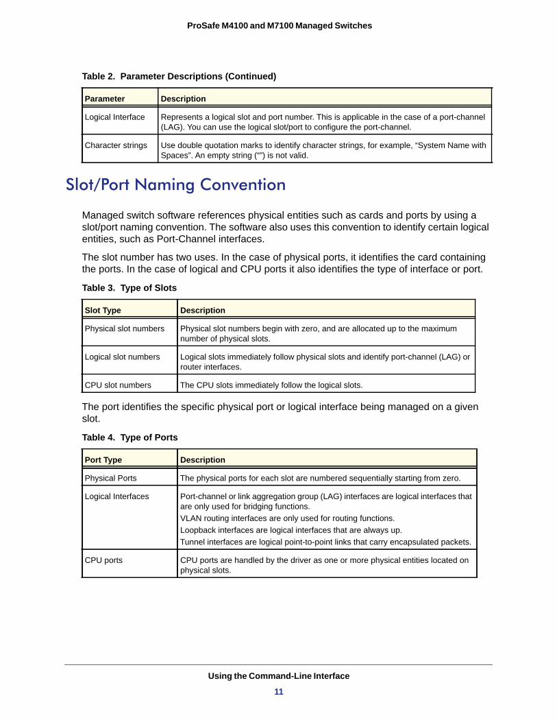
Parameter values might be names (strings) or numbers. To use spaces as part of a name parameter, enclose the name value in double quotes. For example, the expression “System Name with Spaces” forces the system to accept the spaces. Empty strings (““) are not valid user-defined strings. Table 2 describes common parameter values and value formatting.
Symbol Example Description
<> angle brackets Indicates that you must enter a value in place of the brackets and text inside them.
[] square brackets Indicates an optional parameter that you can enter in place of the brackets and text inside them.
{} curly braces Indicates that you must select a parameter from the list of choices.
| Vertical bars Separates the mutually exclusive choices.
[{}] Braces within square brackets
Indicates a choice within an optional element.
Table 2. Parameter Descriptions
Parameter Description
ipaddr This parameter is a valid IP address. You can enter the IP address in the following formats:a (32 bits)a.b (8.24 bits)a.b.c (8.8.16 bits)a.b.c.d (8.8.8.8)
In addition to these formats, the CLI accepts decimal, hexadecimal, and octal formats through the following input formats (where n is any valid hexadecimal, octal, or decimal number):0xn (CLI assumes hexadecimal format)0n (CLI assumes octal format with leading zeros)n (CLI assumes decimal format)
ipv6-address FE80:0000:0000:0000:020F:24FF:FEBF:DBCB, or FE80:0:0:0:20F:24FF:FEBF:DBCB, or FE80::20F24FF:FEBF:DBCB, or FE80:0:0:0:20F:24FF:128:141:49:32
For more information, refer to RFC 3513.
Interface or slot/port
Valid slot and port number separated by forward slashes. For example, 0/1 represents slot number 0 and port number 1.
Using the Command-Line Interface
10
ProSafe M4100 and M7100 Managed Switches
Slot/Port Naming Convention
Managed switch software references physical entities such as cards and ports by using a slot/port naming convention. The software also uses this convention to identify certain logical entities, such as Port-Channel interfaces.
The slot number has two uses. In the case of physical ports, it identifies the card containing the ports. In the case of logical and CPU ports it also identifies the type of interface or port.
Table 3. Type of Slots
The port identifies the specific physical port or logical interface being managed on a given slot.
Table 4. Type of Ports
Logical Interface Represents a logical slot and port number. This is applicable in the case of a port-channel (LAG). You can use the logical slot/port to configure the port-channel.
Character strings Use double quotation marks to identify character strings, for example, “System Name with Spaces”. An empty string (“”) is not valid.
Slot Type Description
Physical slot numbers Physical slot numbers begin with zero, and are allocated up to the maximum number of physical slots.
Logical slot numbers Logical slots immediately follow physical slots and identify port-channel (LAG) or router interfaces.
CPU slot numbers The CPU slots immediately follow the logical slots.
Port Type Description
Physical Ports The physical ports for each slot are numbered sequentially starting from zero.
Logical Interfaces Port-channel or link aggregation group (LAG) interfaces are logical interfaces that are only used for bridging functions. VLAN routing interfaces are only used for routing functions.Loopback interfaces are logical interfaces that are always up.Tunnel interfaces are logical point-to-point links that carry encapsulated packets.
CPU ports CPU ports are handled by the driver as one or more physical entities located on physical slots.
Table 2. Parameter Descriptions (Continued)
Parameter Description
Using the Command-Line Interface
11
ProSafe M4100 and M7100 Managed Switches
Note: In the CLI, loopback and tunnel interfaces do not use the slot/port format. To specify a loopback interface, you use the loopback ID. To specify a tunnel interface, you use the tunnel ID.
Using a Command’s “No” Form
The no keyword is a specific form of an existing command and does not represent a new or distinct command. Almost every configuration command has a no form. In general, use the no form to reverse the action of a command or reset a value back to the default. For example, the no shutdown configuration command reverses the shutdown of an interface. Use the command without the keyword no to reenable a disabled feature or to enable a feature that is disabled by default. Only the configuration commands are available in the no form.
Managed Switch Modules
Managed switch software consists of flexible modules that can be applied in various combinations to develop advanced Layer 2/3/4+ products. The commands and command modes available on your switch depend on the installed modules. Additionally, for some show commands, the output fields might change based on the modules included in the software.
The software suite includes the following modules:
• Switching (Layer 2)• Routing (Layer 3)• IPv6—IPv6 routing• Multicast• Quality of Service• Management (CLI, web UI, and SNMP)• IPv6 Management—Allows management of the device through an IPv6 through an IPv6
address without requiring the IPv6 Routing package in the system. The management address can be associated with the network port (front-panel switch ports) and a routine interface (port or VLAN).
• Stacking
Not all modules are available for all platforms or software releases.
Command Modes
The CLI groups commands into modes according to the command function. Each of the command modes supports specific software commands. The commands in one mode are not available until you switch to that particular mode, except for the User EXEC mode
Using the Command-Line Interface
12
ProSafe M4100 and M7100 Managed Switches
commands. You can execute the User EXEC mode commands in the Privileged EXEC mode.
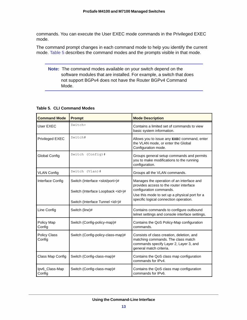
The command prompt changes in each command mode to help you identify the current mode. Table 5 describes the command modes and the prompts visible in that mode.
Note: The command modes available on your switch depend on the software modules that are installed. For example, a switch that does not support BGPv4 does not have the Router BGPv4 Command Mode.
Table 5. CLI Command Modes
Command Mode Prompt Mode Description
User EXEC Switch> Contains a limited set of commands to view basic system information.
Privileged EXEC Switch# Allows you to issue any EXEC command, enter the VLAN mode, or enter the Global Configuration mode.
Global Config Switch (Config)# Groups general setup commands and permits you to make modifications to the running configuration.
VLAN Config Switch (Vlan)# Groups all the VLAN commands.
Interface Config Switch (Interface <slot/port>)#
Switch (Interface Loopback <id>)#
Switch (Interface Tunnel <id>)#
Manages the operation of an interface and provides access to the router interface configuration commands.Use this mode to set up a physical port for a specific logical connection operation.
Line Config Switch (line)# Contains commands to configure outbound telnet settings and console interface settings.
Policy Map Config
Switch (Config-policy-map)# Contains the QoS Policy-Map configuration commands.
Policy Class Config
Switch (Config-policy-class-map)# Consists of class creation, deletion, and matching commands. The class match commands specify Layer 2, Layer 3, and general match criteria.
Class Map Config Switch (Config-class-map)# Contains the QoS class map configuration commands for IPv4.
Ipv6_Class-Map Config
Switch (Config-class-map)# Contains the QoS class map configuration commands for IPv6.
Using the Command-Line Interface
13
ProSafe M4100 and M7100 Managed Switches
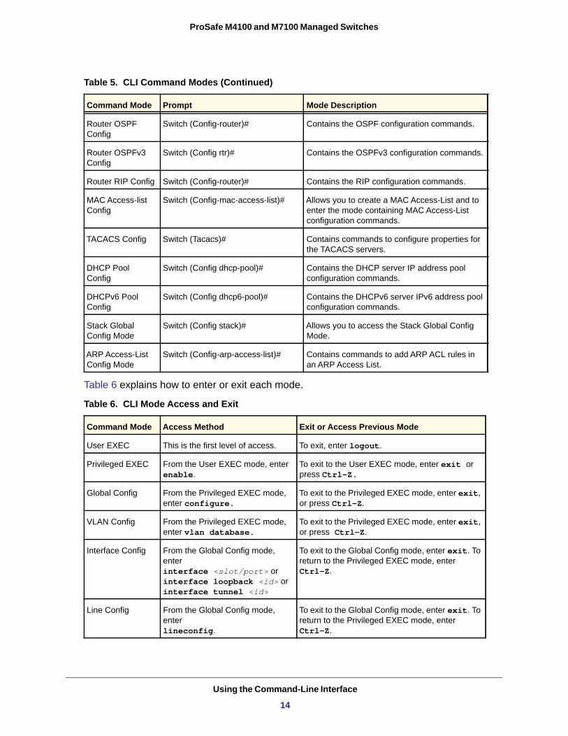
Table 6 explains how to enter or exit each mode.
Router OSPF Config
Switch (Config-router)# Contains the OSPF configuration commands.
Router OSPFv3 Config
Switch (Config rtr)# Contains the OSPFv3 configuration commands.
Router RIP Config Switch (Config-router)# Contains the RIP configuration commands.
MAC Access-list Config
Switch (Config-mac-access-list)# Allows you to create a MAC Access-List and to enter the mode containing MAC Access-List configuration commands.
TACACS Config Switch (Tacacs)# Contains commands to configure properties for the TACACS servers.
DHCP Pool Config
Switch (Config dhcp-pool)# Contains the DHCP server IP address pool configuration commands.
DHCPv6 Pool Config
Switch (Config dhcp6-pool)# Contains the DHCPv6 server IPv6 address pool configuration commands.
Stack Global Config Mode
Switch (Config stack)# Allows you to access the Stack Global Config Mode.
ARP Access-List Config Mode
Switch (Config-arp-access-list)# Contains commands to add ARP ACL rules in an ARP Access List.
Table 6. CLI Mode Access and Exit
Command Mode Access Method Exit or Access Previous Mode
User EXEC This is the first level of access. To exit, enter logout.
Privileged EXEC From the User EXEC mode, enter enable.
To exit to the User EXEC mode, enter exit or press Ctrl-Z.
Global Config From the Privileged EXEC mode, enter configure.
To exit to the Privileged EXEC mode, enter exit, or press Ctrl-Z.
VLAN Config From the Privileged EXEC mode, enter vlan database.
To exit to the Privileged EXEC mode, enter exit, or press Ctrl-Z.
Interface Config From the Global Config mode, enter interface <slot/port> or interface loopback <id> or interface tunnel <id>
To exit to the Global Config mode, enter exit. To return to the Privileged EXEC mode, enter Ctrl-Z.
Line Config From the Global Config mode, enter lineconfig.
To exit to the Global Config mode, enter exit. To return to the Privileged EXEC mode, enter Ctrl-Z.
Table 5. CLI Command Modes (Continued)
Command Mode Prompt Mode Description
Using the Command-Line Interface
14
ProSafe M4100 and M7100 Managed Switches
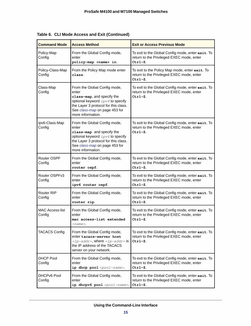
Policy-Map Config
From the Global Config mode, enter policy-map <name> in.
To exit to the Global Config mode, enter exit. To return to the Privileged EXEC mode, enter Ctrl-Z.
Policy-Class-Map Config
From the Policy Map mode enter class.
To exit to the Policy Map mode, enter exit. To return to the Privileged EXEC mode, enter Ctrl-Z.
Class-Map Config
From the Global Config mode, enter class-map, and specify the optional keyword ipv4 to specify the Layer 3 protocol for this class. See class-map on page 453 for more information.
To exit to the Global Config mode, enter exit. To return to the Privileged EXEC mode, enter Ctrl-Z.
Ipv6-Class-Map Config
From the Global Config mode, enter class-map and specify the optional keyword ipv6 to specify the Layer 3 protocol for this class. See class-map on page 453 for more information.
To exit to the Global Config mode, enter exit. To return to the Privileged EXEC mode, enter Ctrl-Z.
Router OSPF Config
From the Global Config mode, enter router ospf.
To exit to the Global Config mode, enter exit. To return to the Privileged EXEC mode, enter Ctrl-Z.
Router OSPFv3 Config
From the Global Config mode, enter ipv6 router ospf.
To exit to the Global Config mode, enter exit. To return to the Privileged EXEC mode, enter Ctrl-Z.
Router RIP Config
From the Global Config mode, enter router rip.
To exit to the Global Config mode, enter exit. To return to the Privileged EXEC mode, enter Ctrl-Z.
MAC Access-list Config
From the Global Config mode, enter mac access-list extended <name>.
To exit to the Global Config mode, enter exit. To return to the Privileged EXEC mode, enter Ctrl-Z.
TACACS Config From the Global Config mode, enter tacacs-server host <ip-addr>, where <ip-addr> is the IP address of the TACACS server on your network.
To exit to the Global Config mode, enter exit. To return to the Privileged EXEC mode, enter Ctrl-Z.
DHCP Pool Config
From the Global Config mode, enter ip dhcp pool <pool-name>.
To exit to the Global Config mode, enter exit. To return to the Privileged EXEC mode, enter Ctrl-Z.
DHCPv6 Pool Config
From the Global Config mode, enter ip dhcpv6 pool <pool-name>.
To exit to the Global Config mode, enter exit. To return to the Privileged EXEC mode, enter Ctrl-Z.
Table 6. CLI Mode Access and Exit (Continued)
Command Mode Access Method Exit or Access Previous Mode
Using the Command-Line Interface
15
ProSafe M4100 and M7100 Managed Switches
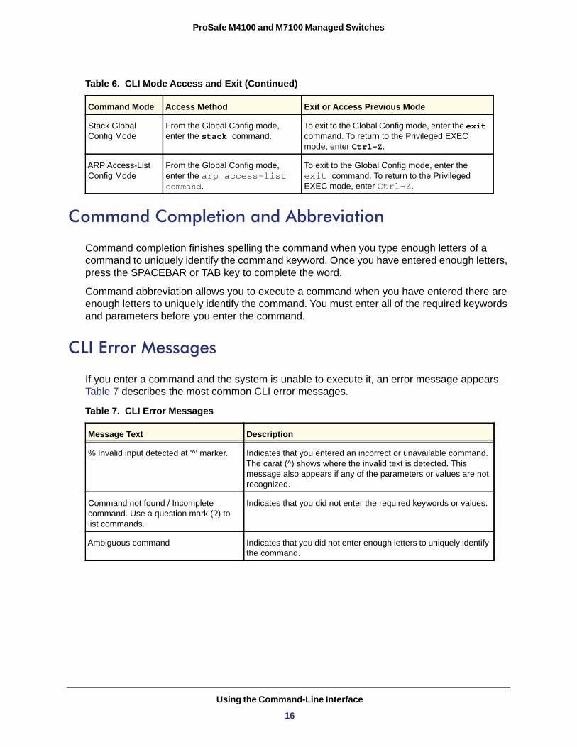
Command Completion and Abbreviation
Command completion finishes spelling the command when you type enough letters of a command to uniquely identify the command keyword. Once you have entered enough letters, press the SPACEBAR or TAB key to complete the word.
Command abbreviation allows you to execute a command when you have entered there are enough letters to uniquely identify the command. You must enter all of the required keywords and parameters before you enter the command.
CLI Error Messages
If you enter a command and the system is unable to execute it, an error message appears. Table 7 describes the most common CLI error messages.
Table 7. CLI Error Messages
Stack Global Config Mode
From the Global Config mode, enter the stack command.
To exit to the Global Config mode, enter the exit command. To return to the Privileged EXEC mode, enter Ctrl-Z.
ARP Access-List Config Mode
From the Global Config mode, enter the arp access-list command.
To exit to the Global Config mode, enter the exit command. To return to the Privileged EXEC mode, enter Ctrl-Z.
Message Text Description
% Invalid input detected at '^' marker. Indicates that you entered an incorrect or unavailable command. The carat (^) shows where the invalid text is detected. This message also appears if any of the parameters or values are not recognized.
Command not found / Incomplete command. Use a question mark (?) to list commands.
Indicates that you did not enter the required keywords or values.
Ambiguous command Indicates that you did not enter enough letters to uniquely identify the command.
Table 6. CLI Mode Access and Exit (Continued)
Command Mode Access Method Exit or Access Previous Mode
Using the Command-Line Interface
16
ProSafe M4100 and M7100 Managed Switches
CLI Line-Editing Conventions
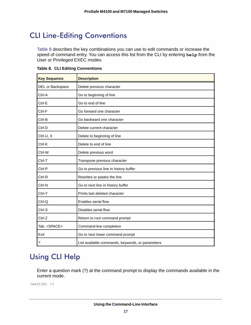
Table 8 describes the key combinations you can use to edit commands or increase the speed of command entry. You can access this list from the CLI by entering help from the User or Privileged EXEC modes.
Table 8. CLI Editing Conventions
Using CLI Help
Enter a question mark (?) at the command prompt to display the commands available in the current mode.
(switch) >?
Key Sequence Description
DEL or Backspace Delete previous character
Ctrl-A Go to beginning of line
Ctrl-E Go to end of line
Ctrl-F Go forward one character
Ctrl-B Go backward one character
Ctrl-D Delete current character
Ctrl-U, X Delete to beginning of line
Ctrl-K Delete to end of line
Ctrl-W Delete previous word
Ctrl-T Transpose previous character
Ctrl-P Go to previous line in history buffer
Ctrl-R Rewrites or pastes the line
Ctrl-N Go to next line in history buffer
Ctrl-Y Prints last deleted character
Ctrl-Q Enables serial flow
Ctrl-S Disables serial flow
Ctrl-Z Return to root command prompt
Tab, <SPACE> Command-line completion
Exit Go to next lower command prompt
? List available commands, keywords, or parameters
Using the Command-Line Interface
17
ProSafe M4100 and M7100 Managed Switches
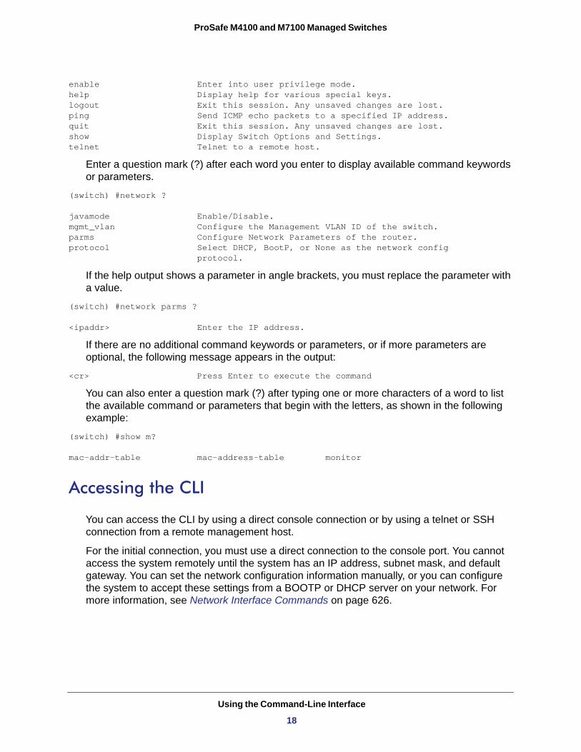
enable Enter into user privilege mode.help Display help for various special keys.logout Exit this session. Any unsaved changes are lost.ping Send ICMP echo packets to a specified IP address.quit Exit this session. Any unsaved changes are lost.show Display Switch Options and Settings.telnet Telnet to a remote host.
Enter a question mark (?) after each word you enter to display available command keywords or parameters.
(switch) #network ?
javamode Enable/Disable.mgmt_vlan Configure the Management VLAN ID of the switch.parms Configure Network Parameters of the router.protocol Select DHCP, BootP, or None as the network config protocol.
If the help output shows a parameter in angle brackets, you must replace the parameter with a value.
(switch) #network parms ?
<ipaddr> Enter the IP address.
If there are no additional command keywords or parameters, or if more parameters are optional, the following message appears in the output:
<cr> Press Enter to execute the command
You can also enter a question mark (?) after typing one or more characters of a word to list the available command or parameters that begin with the letters, as shown in the following example:
(switch) #show m?
mac-addr-table mac-address-table monitor
Accessing the CLI
You can access the CLI by using a direct console connection or by using a telnet or SSH connection from a remote management host.
For the initial connection, you must use a direct connection to the console port. You cannot access the system remotely until the system has an IP address, subnet mask, and default gateway. You can set the network configuration information manually, or you can configure the system to accept these settings from a BOOTP or DHCP server on your network. For more information, see Network Interface Commands on page 626.
Using the Command-Line Interface
18
2
2. Switching CommandsThis chapter describes the switching commands available in the managed switch CLI.
This chapter contains the following sections:
• Port Configuration Commands • Loopback Interface Commands • Spanning Tree Protocol (STP) Commands • VLAN Commands • Double VLAN Commands • Voice VLAN Commands • Provisioning (IEEE 802.1p) Commands • Protected Ports Commands • Private VLAN • GARP Commands • GVRP Commands • GMRP Commands • Port-Based Network Access Control Commands • 802.1X Supplicant Commands • Storm-Control Commands • Flow Control Commands • Port Mirroring • Static MAC Filtering • DHCP L2 Relay Agent Commands • DHCP Client Commands • DHCP Snooping Configuration Commands • Dynamic ARP Inspection Commands • IGMP Snooping Configuration Commands • IGMP Snooping Querier Commands • MLD Snooping Commands • MLD Snooping Querier Commands
19
ProSafe M4100 and M7100 Managed Switches
• Port Security Commands • LLDP (802.1AB) Commands • LLDP-MED Commands • Denial of Service Commands • MAC Database Commands • ISDP Commands • Priority-Based Flow Control Commands
The commands in this chapter are in three functional groups:
• Show commands display switch settings, statistics, and other information.• Configuration commands configure features and options of the switch. Every switch
command has a show command that displays the configuration setting.• Clear commands clear some or all of the settings to factory defaults.
Switching Commands
20
ProSafe M4100 and M7100 Managed Switches
Port Configuration Commands
This section describes the commands you use to view and configure port settings.
interface
This command gives you access to the Interface Config mode, which allows you to enable or modify the operation of an interface (port).
Format interface <slot/port>
Mode
interface vlan
This command gives you access to the vlan virtual interface mode, which allows certain port configurations (for example, the IP address) to be applied to the VLAN interface. Type a question mark (?) after entering the interface configuration mode to see the available options.
Format interface vlan <vlan id>
Mode
interface lag
This command gives you access to the LAG (link aggregation, or port channel) virtual interface, which allows certain port configurations to be applied to the LAG interface. Type a question mark (?) after entering the interface configuration mode to see the available options.
Note: The IP address cannot be assigned to a LAG virtual interface. The interface must be put under a VLAN group and an IP address assigned to the VLAN group.
auto-negotiate
This command enables automatic negotiation on a port.
Default
Format auto-negotiate
Mode
Global Config
Global Config
Format interface lag <lag id>
Mode Global Config
enabled
Interface Config
Switching Commands
21
ProSafe M4100 and M7100 Managed Switches
no auto-negotiate
This command disables automatic negotiation on a port.
Note: Automatic sensing is disabled when automatic negotiation is disabled.
auto-negotiate all
This command enables automatic negotiation on all ports.
Default
Format auto-negotiate all
Mode
no auto-negotiate all
This command disables automatic negotiation on all ports.
Format no auto-negotiate all
Mode
description
Use this command to create an alpha-numeric description of the port.
Format description <description>
Mode
mtu
Use the mtu command to set the maximum transmission unit (MTU) size, in bytes, for frames that ingress or egress the interface. You can use the mtu command to configure jumbo frame support for physical and port-channel (LAG) interfaces. For the standard 7000 series implementation, the MTU size is a valid integer between 1522–9216 for tagged packets and a valid integer between 1518–9216 for untagged packets.
Note: To receive and process packets, the Ethernet MTU must include any extra bytes that Layer-2 headers might require. To configure the IP MTU size, which is the maximum size of the IP packet (IP Header + IP payload), see ip mtu on page 233.
enabled
Global Config
Global Config
Interface Config
Switching Commands
22
ProSafe M4100 and M7100 Managed Switches
no mtu
This command sets the default MTU size (in bytes) for the interface.
Format no mtu
Mode
shutdown
This command disables a port.
Note: You can use the shutdown command on physical and port-channel (LAG) interfaces, but not on VLAN routing interfaces.
no shutdown
This command enables a port.
Format no shutdown
Mode
shutdown all
This command disables all ports.
Note: You can use the shutdown all command on physical and port-channel (LAG) interfaces, but not on VLAN routing interfaces.
Default 1518 (untagged)
Format mtu <1518-9216>
Mode Interface Config
Interface Config
Format shutdown
Mode Interface Config
Interface Config
Format shutdown all
Mode Global Config
Switching Commands
23
ProSafe M4100 and M7100 Managed Switches
no shutdown all
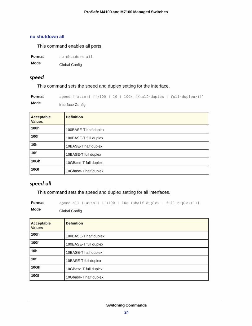
This command enables all ports.
Format no shutdown all
Mode
speed
This command sets the speed and duplex setting for the interface.
Format speed [{auto}] [{<100 | 10 | 10G> {<half-duplex | full-duplex>}}]
Mode
100h
100f
10h
10f
10Gh
10Gf
speed all
This command sets the speed and duplex setting for all interfaces.
Format speed all [{auto}] [{<100 | 10> {<half-duplex | full-duplex>}}]
Mode
100h
100f
10h
10f
10Gh
10Gf
Global Config
Interface Config
Acceptable Values
Definition
100BASE-T half duplex
100BASE-T full duplex
10BASE-T half duplex
10BASE-T full duplex
10GBase-T full duplex
10Gbase-T half duplex
Global Config
Acceptable Values
Definition
100BASE-T half duplex
100BASE-T full duplex
10BASE-T half duplex
10BASE-T full duplex
10GBase-T full duplex
10Gbase-T half duplex
Switching Commands
24
ProSafe M4100 and M7100 Managed Switches
show port advertise
Use this command to display the local administrative link advertisement configuration, local operational link advertisement, and the link partner advertisement for an interface. It also displays priority Resolution for speed and duplex as per 802.3 Annex 28B.3. It displays the autonegotiation state, Phy Master/Slave Clock configuration, and Link state of the port.
If the link is down, the Clock is displayed as No Link, and a dash is displayed against the Oper Peer advertisement, and Priority Resolution. If autonegotiation is disabled, the admin Local Link advertisement, operational local link advertisement, operational peer advertisement, and Priority resolution fields are not displayed.
If this command is executed without the optional slot/port parameter, it displays the autonegotiation state and operational Local link advertisement for all the ports. Operational link advertisement will display speed only if it is supported by both local as well as link partner. If autonegotiation is disabled, operational local link advertisement is not displayed.
Format show port advertise [slot/port]
Mode
Example: The following commands show the command output with and without the optional parameter:
(switch)#show port advertise 0/1
Port: 0/1Type: Gigabit - LevelLink State: DownAuto Negotiation: EnabledClock: Auto 1000f 1000h 100f 100h 10f 10h ----- ----- ---- ---- --- ---Admin Local Link Advertisement no no yes no yes noOper Local Link Advertisement no no yes no yes noOper Peer Advertisement no no yes yes yes yesPriority Resolution - - yes - - -
(Netgear Switch)#show port advertise
Port Type Neg Operational Link Advertisement--------- ------------------------------ ----------- ------------------------------0/1 Gigabit - Level Enabled 1000f, 100f, 100h, 10f, 10h0/2 Gigabit - Level Enabled 1000f, 100f, 100h, 10f, 10h0/3 Gigabit - Level Enabled 1000f, 100f, 100h, 10f, 10h
show port
This command displays port information.
Format show port {<slot/port> | all}
Mode
Privileged EXEC
Privileged EXEC
Switching Commands
25
ProSafe M4100 and M7100 Managed Switches
Interface
Type
• Mirror - this port is a monitoring port. For more information, see Port Mirroring on page 121.
• PC Mbr- this port is a member of a port-channel (LAG).• Probe - this port is a probe port.
Admin Mode
Physical Mode
Physical Status
Link Status
Link Trap
LACP Mode
show port protocol
This command displays the Protocol-Based VLAN information for either the entire system, or for the indicated group.
Format show port protocol {<groupid> | all}
Mode
Term Definition
Valid slot and port number separated by forward slashes.
If not blank, this field indicates that this port is a special type of port. The possible values are:
The Port control administration state. The port must be enabled in order for it to be allowed into the network. - May be enabled or disabled. The factory default is enabled.
The desired port speed and duplex mode. If autonegotiation support is selected, the duplex mode and speed is set from the auto-negotiation process. Note that the maximum capability of the port (full-duplex -100M) is advertised. Otherwise, this object determines the port's duplex mode and transmission rate. The factory default is Auto.
The port speed and duplex mode.
The Link is up or down.
This object determines whether to send a trap when link status changes. The factory default is enabled.
LACP is enabled or disabled on this port.
Privileged EXEC
Term Definition
Group Name The group name of an entry in the Protocol-based VLAN table.
Group ID The group identifier of the protocol group.
Protocol(s) The type of protocol(s) for this group.
VLAN The VLAN associated with this Protocol Group.
Interface(s) Lists the slot/port interface(s) that are associated with this Protocol Group.
Switching Commands
26
ProSafe M4100 and M7100 Managed Switches
show port description
This command displays the port description for every port.
Format show port description <slot/port>
Mode
Interface
Description
show port status
This command displays the Protocol-Based VLAN information for either the entire system, or for the indicated group.
Format show port status {<slot/port> | all}
Mode
Interface
Media Type
STP Mode
Physical Mode
Physical Status
Link Status
Loop Status
Partner Flow Control
Loopback Interface Commands
The commands in this section describe how to create, delete, and manage loopback interfaces. A loopback interface is always expected to be up. This interface can provide the source address for sent packets and can receive both local and remote packets. The loopback interface is typically used by routing protocols.
To assign an IP address to the loopback interface, see ip address on page 228. To assign an IPv6 address to the loopback interface, see ipv6 address on page 359.
Privileged EXEC
Term Definition
Valid slot and port number separated by forward slashes
Shows the port description configured via the “description” command
Privileged EXEC
Term Definition
Valid slot and port number separated by forward slashes.
“Copper” or “Fiber” for combo port.
Indicate the spanning tree mode of the port.
Either “Auto” or fixed speed and duplex mode.
The actual speed and duplex mode.
Whether the link is Up or Down.
Whether the port is in loop state or not.
Whether the remote side is using flow control or not.
Switching Commands
27
ProSafe M4100 and M7100 Managed Switches
interface loopback
Use this command to enter the Interface Config mode for a loopback interface. The range of the loopback ID is 0–7.
Format interface loopback <loopback-id>
Mode
no interface loopback
This command removes the loopback interface and associated configuration parameters for the specified loopback interface.
Format no interface loopback <loopback-id>
Mode
show interface loopback
This command displays information about configured loopback interfaces.
Format show interface loopback [<loopback-id>]
Mode
If you do not specify a loopback ID, the following information appears for each loopback interface on the system:
Loopback ID
Interface
IP Address
Received Packets
Sent Packets
IPv6 Address
If you specify a loopback ID, the following information appears:
Global Config
Global Config
Privileged EXEC
Term Definition
The loopback ID associated with the rest of the information in the row.
The interface name.
The IPv4 address of the interface.
The number of packets received on this interface.
The number of packets transmitted from this interface.
The IPv6 address of this interface.
Term Definition
Interface Link Status Shows whether the link is up or down.
IP Address The IPv4 address of the interface.
IPv6 is enabled (disabled) Shows whether IPv6 is enabled on the interface.
Switching Commands
28
ProSafe M4100 and M7100 Managed Switches
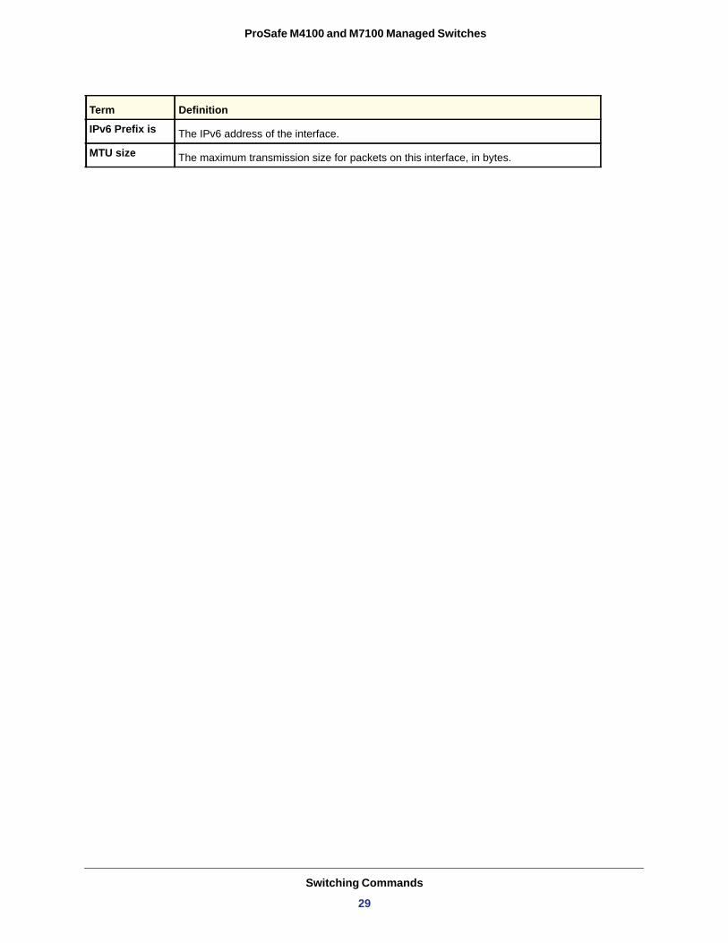
IPv6 Prefix is The IPv6 address of the interface.
MTU size The maximum transmission size for packets on this interface, in bytes.
Term Definition
Switching Commands
29
ProSafe M4100 and M7100 Managed Switches
Spanning Tree Protocol (STP) Commands
This section describes the commands you use to configure Spanning Tree Protocol (STP). STP helps prevent network loops, duplicate messages, and network instability.
spanning-tree
This command sets the spanning-tree operational mode to enabled.
Default
Format spanning-tree
Mode
no spanning-tree
This command sets the spanning-tree operational mode to disabled. While disabled, the spanning-tree configuration is retained and can be changed, but is not activated.
Format no spanning-tree
Mode
spanning-tree auto-edge
This command enables auto-edge on the interface or range of interfaces. When enabled, the interface becomes an edge port if it does not see BPDUs for edge delay time.
Default
Format spanning-tree auto-edge
Mode
no spanning-tree auto-edge
This command disables auto-edge on the interface or range of interfaces.
Format no spanning-tree auto-edge
Mode
spanning-tree bpdufilter
Use this command to enable BPDU Filter on an interface or range of interfaces.
Default
Format spanning-tree bpdufilter
Mode
enabled
Global Config
Global Config
enabled
Interface Config
Interface Config
disabled
Interface Config
Switching Commands
30
ProSafe M4100 and M7100 Managed Switches
no spanning-tree bpdufilter
Use this command to disable BPDU Filter on the interface or range of interfaces.
Default
Format no spanning-tree bpdufilter
Mode
spanning-tree bpdufilter default
Use this command to enable BPDU Filter on all the edge port interfaces.
Default
Format spanning-tree bpdufilter
Mode
no spanning-tree bpdufilter default
Use this command to disable BPDU Filter on all the edge port interfaces.
Default
Format no spanning-tree bpdufilter default
Mode
spanning-tree bpduflood
Use this command to enable BPDU Flood on the interface.
Default
Format spanning-tree bpduflood
Mode
no spanning-tree bpduflood
Use this command to disable BPDU Flood on the interface.
Format no spanning-tree bpduflood
Mode
disabled
Interface Config
disabled
Global Config
enabled
Global Config
disabled
Interface Config
Interface Config
Switching Commands
31
ProSafe M4100 and M7100 Managed Switches
spanning-tree bpduguard
Use this command to enable BPDU Guard on the switch.
Default
Format spanning-tree bpduguard
Mode
no spanning-tree bpduguard
Use this command to disable BPDU Guard on the switch.
Format no spanning-tree bpduguard
Mode
spanning-tree bpdumigrationcheck
Use this command to force a transmission of rapid spanning tree (RSTP) and multiple spanning tree (MSTP) BPDUs. Use the <slot/port> parameter to transmit a BPDU from a specified interface, or use the all keyword to transmit BPDUs from all interfaces. This command forces the BPDU transmission when you execute it, so the command does not change the system configuration or have a “no” version.
Format spanning-tree bpdumigrationcheck {<slot/port> | all}
Mode
spanning-tree configuration name
This command sets the Configuration Identifier Name for use in identifying the configuration that this switch is currently using. The <name> is a string of up to 32 characters.
Default
Format spanning-tree configuration name <name>Mode
no spanning-tree configuration name
This command resets the Configuration Identifier Name to its default.
Format no spanning-tree configuration name
Mode
disabled
Global Config
Global Config
Global Config
base MAC address in hexadecimal notation
Global Config
Global Config
Switching Commands
32
ProSafe M4100 and M7100 Managed Switches
spanning-tree configuration revision
This command sets the Configuration Identifier Revision Level for use in identifying the configuration that this switch is currently using. The Configuration Identifier Revision Level is a number in the range of 0–65535.
Default
Format spanning-tree configuration revision <0-65535>Mode
no spanning-tree configuration revision
This command sets the Configuration Identifier Revision Level for use in identifying the configuration that this switch is currently using to the default value.
Format no spanning-tree configuration revision Mode
spanning-tree edgeport
This command specifies that this port is an Edge Port within the Common and Internal Spanning Tree. This allows this port to transition to Forwarding State without delay.
Default enabled
Format spanning-tree edgeport
Mode
no spanning-tree edgeport
This command specifies that this port is not an Edge Port within the Common and Internal Spanning Tree.
Format no spanning-tree edgeport
Mode
spanning-tree forceversion
This command sets the Force Protocol Version parameter to a new value.
Default
Format spanning-tree forceversion <802.1d | 802.1s | 802.1w>Mode
• Use 802.1d to specify that the switch transmits ST BPDUs rather than MST BPDUs (IEEE 802.1d functionality supported).
0
Global Config
Global Config
Interface Config
Interface Config
802.1s
Global Config
Switching Commands
33
ProSafe M4100 and M7100 Managed Switches
• Use 802.1s to specify that the switch transmits MST BPDUs (IEEE 802.1s functionality supported).
• Use 802.1w to specify that the switch transmits RST BPDUs rather than MST BPDUs (IEEE 802.1w functionality supported).
no spanning-tree forceversion
This command sets the Force Protocol Version parameter to the default value.
Format no spanning-tree forceversion Mode
spanning-tree forward-time
This command sets the Bridge Forward Delay parameter to a new value for the Common and Internal Spanning Tree. The forward-time value is in seconds within a range of 4–30, with the value being greater than or equal to “(Bridge Max Age / 2) + 1”.
Default
Format spanning-tree forward-time <4-30>Mode
no spanning-tree forward-time
This command sets the Bridge Forward Delay parameter for the Common and Internal Spanning Tree to the default value.
Format no spanning-tree forward-time Mode
spanning-tree guard
This command selects whether loop guard or root guard is enabled on an interface. If neither is enabled, the port operates in accordance with the multiple spanning tree protocol.
Default
Format spanning-tree guard { none | root | loop }
Mode
no spanning-tree guard
This command disables loop guard or root guard on the interface.
Format no spanning-tree guard
Mode
Global Config
15
Global Config
Global Config
none
Interface Config
Interface Config
Switching Commands
34
ProSafe M4100 and M7100 Managed Switches
spanning-tree tcnguard
This command enables the propagation of received topology change notifications and topology changes to other ports.
Default
Format spanning-tree tcnguard
Mode
no spanning-tree tcnguard
This command disables the propagation of received topology change notifications and topology changes to other ports.
Format no spanning-tree tcnguard
Mode
spanning-tree max-age
This command sets the Bridge Max Age parameter to a new value for the Common and Internal Spanning Tree. The max-age value is in seconds within a range of 6–40, with the value being less than or equal to 2 x (Bridge Forward Delay - 1).
Default
Format spanning-tree max-age <6-40>Mode
no spanning-tree max-age
This command sets the Bridge Max Age parameter for the Common and Internal Spanning Tree to the default value.
Format no spanning-tree max-age
Mode
spanning-tree max-hops
This command sets the MSTP Max Hops parameter to a new value for the Common and Internal Spanning Tree. The max-hops value is a range from 6 to 40.
Default
Format spanning-tree max-hops <1-127>
Mode
disable
Interface Config
Interface Config
20
Global Config
Global Config
20
Global Config
Switching Commands
35
ProSafe M4100 and M7100 Managed Switches
no spanning-tree max-hops
This command sets the Bridge Max Hops parameter for the Common and Internal Spanning Tree to the default value.
Format no spanning-tree max-hops
Mode
spanning-tree mst
This command sets the Path Cost or Port Priority for this port within the multiple spanning tree instance or in the Common and Internal Spanning Tree. If you specify an <mstid> parameter that corresponds to an existing multiple spanning tree instance, the configurations are done for that multiple spanning tree instance. If you specify 0 (defined as the default CIST ID) as the <mstid>, the configurations are done for the Common and Internal Spanning Tree instance.
If you specify the cost option, the command sets the path cost for this port within a multiple spanning tree instance or the Common and Internal Spanning Tree instance, depending on the <mstid> parameter. You can set the path cost as a number in the range of 1–200000000 or auto. If you select auto the path cost value is set based on Link Speed.
If you specify the external-cost option, this command sets the external-path cost for MST instance ‘0’ that is, CIST instance. You can set the external cost as a number in the range of 1–200000000 or auto. If you specify auto, the external path cost value is set based on Link Speed.
If you specify the port-priority option, this command sets the priority for this port within a specific multiple spanning tree instance or the Common and Internal Spanning Tree instance, depending on the <mstid> parameter. The port-priority value is a number in the range of 0–240 in increments of 16.
Default • cost—auto• external-cost—auto• port-priority—128
Format spanning-tree mst <mstid> {{cost <1-200000000> | auto} | {external-cost <1-200000000> | auto} | port-priority <0-240>}
Mode
no spanning-tree mst
This command sets the Path Cost or Port Priority for this port within the multiple spanning tree instance, or in the Common and Internal Spanning Tree to the respective default values. If you specify an <mstid> parameter that corresponds to an existing multiple spanning tree instance, you are configuring that multiple spanning tree instance. If you specify 0 (defined as the default CIST ID) as the <mstid>, you are configuring the Common and Internal Spanning Tree instance.
Global Config
Interface Config
Switching Commands
36
ProSafe M4100 and M7100 Managed Switches
If you specify cost, this command sets the path cost for this port within a multiple spanning tree instance or the Common and Internal Spanning Tree instance, depending on the <mstid> parameter, to the default value, that is, a path cost value based on the Link Speed.
If you specify external-cost, this command sets the external path cost for this port for mst ‘0’ instance, to the default value, that is, a path cost value based on the Link Speed.
If you specify port-priority, this command sets the priority for this port within a specific multiple spanning tree instance or the Common and Internal Spanning Tree instance, depending on the <mstid> parameter, to the default value.
Format no spanning-tree mst <mstid> <cost | external-cost | port-priority>
Mode
spanning-tree mst instance
This command adds a multiple spanning tree instance to the switch. The parameter <mstid> is a number within a range of 1–4094, that corresponds to the new instance ID to be added. The maximum number of multiple instances supported by the switch is 4.
Default
Format spanning-tree mst instance <mstid>
Mode
no spanning-tree mst instance
This command removes a multiple spanning tree instance from the switch and reallocates all VLANs allocated to the deleted instance to the Common and Internal Spanning Tree. The parameter <mstid> is a number that corresponds to the desired existing multiple spanning tree instance to be removed.
Format no spanning-tree mst instance <mstid>
Mode
spanning-tree mst priority
This command sets the bridge priority for a specific multiple spanning tree instance. The parameter <mstid> is a number that corresponds to the desired existing multiple spanning tree instance. The priority value is a number within a range of 0–61440 in increments of 4096.
If you specify 0 (defined as the default CIST ID) as the <mstid>, this command sets the Bridge Priority parameter to a new value for the Common and Internal Spanning Tree. The bridge priority value is a number within a range of 0–61440. The twelve least significant bits
Interface Config
none
Global Config
Global Config
Switching Commands
37
ProSafe M4100 and M7100 Managed Switches
are masked according to the 802.1s specification. This causes the priority to be rounded down to the next lower valid priority.
Default
Format spanning-tree mst priority <mstid> <0-61440>Mode
no spanning-tree mst priority
This command sets the bridge priority for a specific multiple spanning tree instance to the default value. The parameter <mstid> is a number that corresponds to the desired existing multiple spanning tree instance.
If 0 (defined as the default CIST ID) is passed as the <mstid>, this command sets the Bridge Priority parameter for the Common and Internal Spanning Tree to the default value.
Format no spanning-tree mst priority <mstid>Mode
spanning-tree mst vlan
This command adds an association between a multiple spanning tree instance and one or more VLANs so that the VLAN(s) are no longer associated with the Common and Internal Spanning Tree. The parameter <mstid> is a number that corresponds to the desired existing multiple spanning tree instance. The vlan range can be specified as a list or as a range of values. To specify a list of VLANs, enter a list of VLAN IDs, each separated by a comma with no spaces in between. To specify a range of VLANs, separate the beginning and ending VLAN ID with a dash ("-").
Format spanning-tree mst vlan <mstid> <vlanid>
Mode
no spanning-tree mst vlan
This command removes an association between a multiple spanning tree instance and one or more VLANs so that the VLAN(s) are again associated with the Common and Internal Spanning Tree.
Format no spanning-tree mst vlan <mstid> <vlanid>
Mode
32768
Global Config
Global Config
Global Config
Global Config
Switching Commands
38
ProSafe M4100 and M7100 Managed Switches
spanning-tree port mode
This command sets the Administrative Switch Port State for this port to enabled.
Default
Format spanning-tree port mode
Mode
no spanning-tree port mode
This command sets the Administrative Switch Port State for this port to disabled.
Format no spanning-tree port mode
Mode
spanning-tree port mode all
This command sets the Administrative Switch Port State for all ports to enabled.
Default
Format spanning-tree port mode all
Mode
no spanning-tree port mode all
This command sets the Administrative Switch Port State for all ports to disabled.
Format no spanning-tree port mode all
Mode
spanning-tree edgeport all
This command specifies that every port is an Edge Port within the Common and Internal Spanning Tree. This allows all ports to transition to Forwarding State without delay.
Format spanning-tree edgeport all
Mode
no spanning-tree edgeport all
This command disables Edge Port mode for all ports within the Common and Internal Spanning Tree.
Format no spanning-tree edgeport all
Mode
enabled
Interface Config
Interface Config
enabled
Global Config
Global Config
Global Config
Global Config
Switching Commands
39
ProSafe M4100 and M7100 Managed Switches
spanning-tree bpduforwarding
Normally a switch will not forward Spanning Tree Protocol (STP) BPDU packets if STP is disabled. However, if in some network setup, the user wishes to forward BDPU packets received from other network devices, this command can be used to enable the forwarding.
Default
Format spanning-tree bpduforwarding
Mode
no spanning-tree bpduforwarding
This command will cause the STP BPDU packets received from the network to be dropped if STP is disabled.
Format no spanning-tree bpduforwarding
Mode
show spanning-tree
This command displays spanning tree settings for the Common and Internal Spanning Tree. The following details are displayed.
Format show spanning-tree
Mode • Privileged EXEC• User EXEC
disabled
Global Config
Global Config
Term Definition
Bridge Priority Specifies the bridge priority for the Common and Internal Spanning Tree (CST). The value lies between 0 and 61440. It is displayed in multiples of 4096.
Bridge Identifier The bridge identifier for the CST. It is made up using the bridge priority and the base MAC address of the bridge.
Time Since Topology Change
Time in seconds.
Topology Change Count Number of times changed.
Topology Change Boolean value of the Topology Change parameter for the switch indicating if a topology
change is in progress on any port assigned to the Common and Internal Spanning Tree.
Designated Root The bridge identifier of the root bridge. It is made up from the bridge priority and the base
MAC address of the bridge.
Root Path Cost Value of the Root Path Cost parameter for the Common and Internal Spanning Tree.
Switching Commands
40
ProSafe M4100 and M7100 Managed Switches
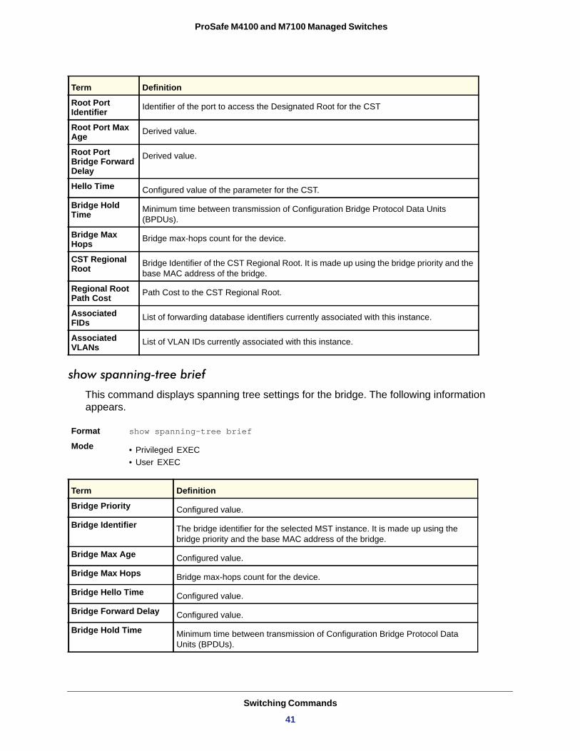
show spanning-tree brief
This command displays spanning tree settings for the bridge. The following information appears.
Format show spanning-tree brief
Mode • Privileged EXEC• User EXEC
Bridge Priority
Bridge Identifier
Bridge Max Age
Bridge Max Hops
Bridge Hello Time
Bridge Forward Delay
Bridge Hold Time
Root Port Identifier Identifier of the port to access the Designated Root for the CST
Root Port Max Age Derived value.
Root Port Bridge Forward Delay
Derived value.
Hello Time Configured value of the parameter for the CST.
Bridge Hold Time Minimum time between transmission of Configuration Bridge Protocol Data Units
(BPDUs).
Bridge Max Hops Bridge max-hops count for the device.
CST Regional Root Bridge Identifier of the CST Regional Root. It is made up using the bridge priority and the
base MAC address of the bridge.
Regional Root Path Cost Path Cost to the CST Regional Root.
Associated FIDs List of forwarding database identifiers currently associated with this instance.
Associated VLANs List of VLAN IDs currently associated with this instance.
Term Definition
Configured value.
The bridge identifier for the selected MST instance. It is made up using the bridge priority and the base MAC address of the bridge.
Configured value.
Bridge max-hops count for the device.
Configured value.
Configured value.
Minimum time between transmission of Configuration Bridge Protocol Data Units (BPDUs).
Term Definition
Switching Commands
41

ProSafe M4100 and M7100 Managed Switches
show spanning-tree interface
This command displays the settings and parameters for a specific switch port within the Common and Internal Spanning Tree. The <slot/port> is the desired switch port. The following details are displayed on execution of the command.
Format show spanning-tree interface <slot/port>Mode • Privileged EXEC
• User EXEC
Hello Time
Port Mode
BPDU Guard Effect
Root Guard
Loop Guard
TCN Guard
BPDU Filter Mode
BPDU Flood Mode
Auto Edge
Port Up Time Since Counters Last Cleared
STP BPDUs Transmitted
STP BPDUs Received
RSTP BPDUs Transmitted
RSTP BPDUs Received
MSTP BPDUs Transmitted
MSTP BPDUs Received
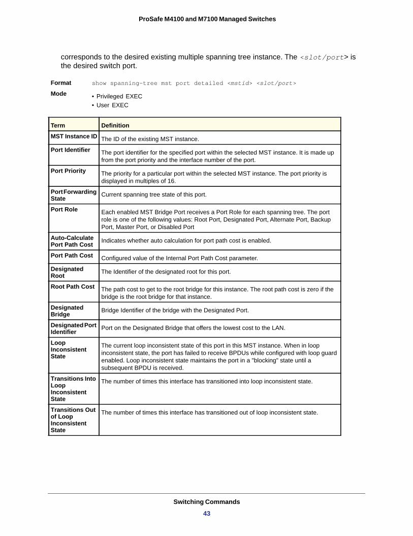
show spanning-tree mst port detailed
This command displays the detailed settings and parameters for a specific switch port within a particular multiple spanning tree instance. The parameter <mstid> is a number that
Term Definition
Admin hello time for this port.
Enabled or disabled.
Enabled or disabled.
Enabled or disabled.
Enabled or disabled.
Enable or disable the propagation of received topology change notifications and topology changes to other ports.
Enabled or disabled.
Enabled or disabled.
To enable or disable the feature that causes a port that has not seen a BPDU for ‘edge delay’ time, to become an edge port and transition to forwarding faster.
Time since port was reset, displayed in days, hours, minutes, and seconds.
Spanning Tree Protocol Bridge Protocol Data Units sent.
Spanning Tree Protocol Bridge Protocol Data Units received.
Rapid Spanning Tree Protocol Bridge Protocol Data Units sent.
Rapid Spanning Tree Protocol Bridge Protocol Data Units received.
Multiple Spanning Tree Protocol Bridge Protocol Data Units sent.
Multiple Spanning Tree Protocol Bridge Protocol Data Units received.
Switching Commands
42
ProSafe M4100 and M7100 Managed Switches
corresponds to the desired existing multiple spanning tree instance. The <slot/port> is the desired switch port.
Format show spanning-tree mst port detailed <mstid> <slot/port>
Mode • Privileged EXEC• User EXEC
MST Instance ID
Port Identifier
Port Priority
Port Forwarding State
Port Role
Auto-Calculate Port Path Cost
Port Path Cost
Designated Root
Root Path Cost
Designated Bridge
Designated Port Identifier
Loop Inconsistent State
Transitions Into Loop Inconsistent State
Transitions Out of Loop Inconsistent State
Term Definition
The ID of the existing MST instance.
The port identifier for the specified port within the selected MST instance. It is made up from the port priority and the interface number of the port.
The priority for a particular port within the selected MST instance. The port priority is displayed in multiples of 16.
Current spanning tree state of this port.
Each enabled MST Bridge Port receives a Port Role for each spanning tree. The port role is one of the following values: Root Port, Designated Port, Alternate Port, Backup Port, Master Port, or Disabled Port
Indicates whether auto calculation for port path cost is enabled.
Configured value of the Internal Port Path Cost parameter.
The Identifier of the designated root for this port.
The path cost to get to the root bridge for this instance. The root path cost is zero if the bridge is the root bridge for that instance.
Bridge Identifier of the bridge with the Designated Port.
Port on the Designated Bridge that offers the lowest cost to the LAN.
The current loop inconsistent state of this port in this MST instance. When in loop inconsistent state, the port has failed to receive BPDUs while configured with loop guard enabled. Loop inconsistent state maintains the port in a "blocking" state until a subsequent BPDU is received.
The number of times this interface has transitioned into loop inconsistent state.
The number of times this interface has transitioned out of loop inconsistent state.
Switching Commands
43
ProSafe M4100 and M7100 Managed Switches
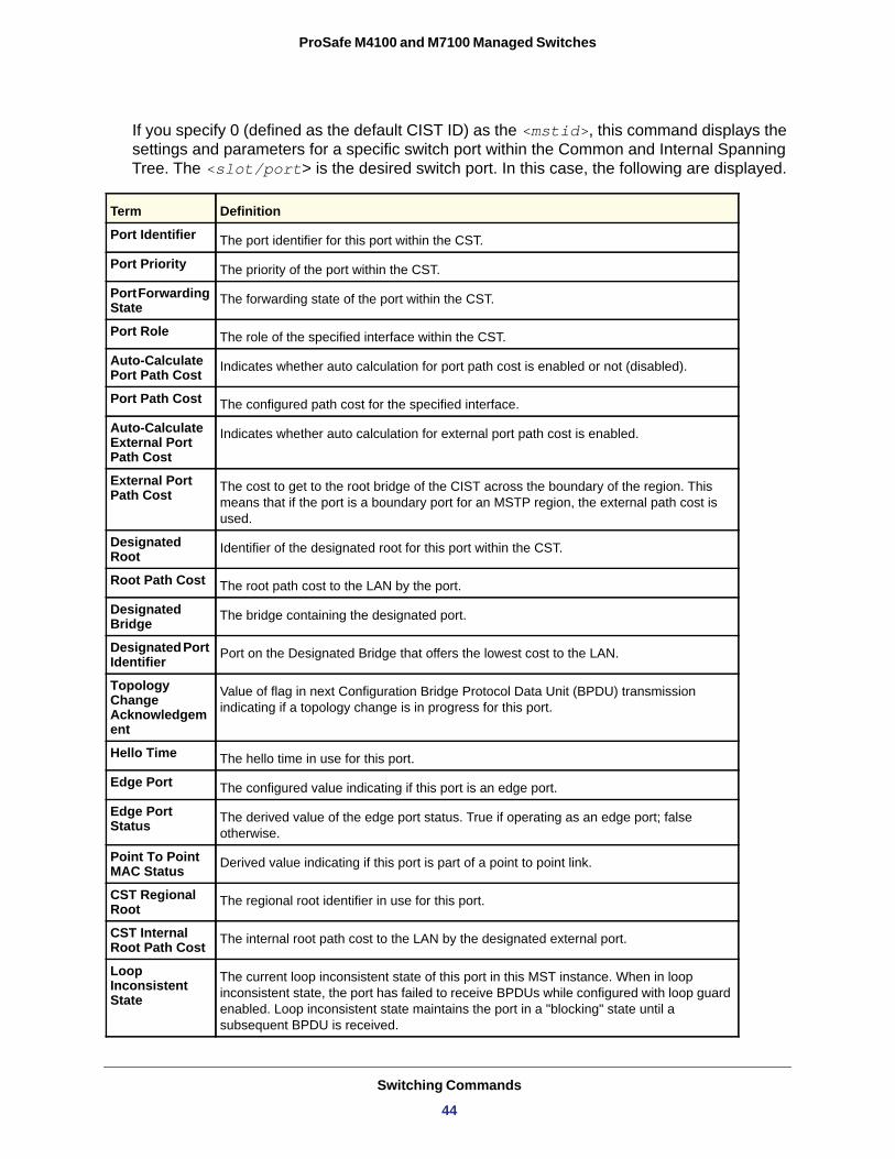
If you specify 0 (defined as the default CIST ID) as the <mstid>, this command displays the settings and parameters for a specific switch port within the Common and Internal Spanning Tree. The <slot/port> is the desired switch port. In this case, the following are displayed.
Term Definition
Port Identifier The port identifier for this port within the CST.
Port Priority The priority of the port within the CST.
Port Forwarding State The forwarding state of the port within the CST.
Port Role The role of the specified interface within the CST.
Auto-Calculate Port Path Cost Indicates whether auto calculation for port path cost is enabled or not (disabled).
Port Path Cost The configured path cost for the specified interface.
Auto-Calculate External Port Path Cost
Indicates whether auto calculation for external port path cost is enabled.
External Port Path Cost The cost to get to the root bridge of the CIST across the boundary of the region. This
means that if the port is a boundary port for an MSTP region, the external path cost is used.
Designated Root Identifier of the designated root for this port within the CST.
Root Path Cost The root path cost to the LAN by the port.
Designated Bridge The bridge containing the designated port.
Designated Port Identifier Port on the Designated Bridge that offers the lowest cost to the LAN.
Topology Change Acknowledgement
Value of flag in next Configuration Bridge Protocol Data Unit (BPDU) transmission indicating if a topology change is in progress for this port.
Hello Time The hello time in use for this port.
Edge Port The configured value indicating if this port is an edge port.
Edge Port Status The derived value of the edge port status. True if operating as an edge port; false
otherwise.
Point To Point MAC Status Derived value indicating if this port is part of a point to point link.
CST Regional Root The regional root identifier in use for this port.
CST Internal Root Path Cost The internal root path cost to the LAN by the designated external port.
Loop Inconsistent State
The current loop inconsistent state of this port in this MST instance. When in loop inconsistent state, the port has failed to receive BPDUs while configured with loop guard enabled. Loop inconsistent state maintains the port in a "blocking" state until a subsequent BPDU is received.
Switching Commands
44
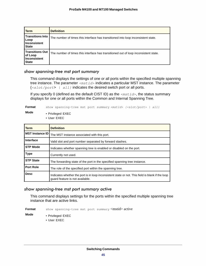
ProSafe M4100 and M7100 Managed Switches
show spanning-tree mst port summary
This command displays the settings of one or all ports within the specified multiple spanning tree instance. The parameter <mstid> indicates a particular MST instance. The parameter {<slot/port> | all} indicates the desired switch port or all ports.
If you specify 0 (defined as the default CIST ID) as the <mstid>, the status summary displays for one or all ports within the Common and Internal Spanning Tree.
Format show spanning-tree mst port summary <mstid> {<slot/port> | all}Mode • Privileged EXEC
• User EXEC
MST Instance ID
Interface
STP Mode
Type
STP State
Port Role
Desc
show spanning-tree mst port summary active
This command displays settings for the ports within the specified multiple spanning tree instance that are active links.
Format show spanning-tree mst port summary <mstid> activeMode • Privileged EXEC
• User EXEC
Transitions Into Loop Inconsistent State
The number of times this interface has transitioned into loop inconsistent state.
Transitions Out of Loop Inconsistent State
The number of times this interface has transitioned out of loop inconsistent state.
Term Definition
The MST instance associated with this port.
Valid slot and port number separated by forward slashes.
Indicates whether spanning tree is enabled or disabled on the port.
Currently not used.
The forwarding state of the port in the specified spanning tree instance.
The role of the specified port within the spanning tree.
Indicates whether the port is in loop inconsistent state or not. This field is blank if the loop guard feature is not available.
Term Definition
Switching Commands
45
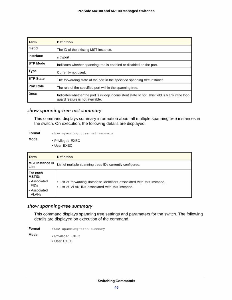
ProSafe M4100 and M7100 Managed Switches
show spanning-tree mst summary
This command displays summary information about all multiple spanning tree instances in the switch. On execution, the following details are displayed.
Format show spanning-tree mst summary Mode • Privileged EXEC
• User EXEC
MST Instance ID List
For each MSTID:• Associated
FIDs• Associated
VLANs
• List of forwarding database identifiers associated with this instance.• List of VLAN IDs associated with this instance.
show spanning-tree summary
This command displays spanning tree settings and parameters for the switch. The following details are displayed on execution of the command.
Format show spanning-tree summary Mode • Privileged EXEC
• User EXEC
Term Definition
mstid The ID of the existing MST instance.
Interface slot/port
STP Mode Indicates whether spanning tree is enabled or disabled on the port.
Type Currently not used.
STP State The forwarding state of the port in the specified spanning tree instance.
Port Role The role of the specified port within the spanning tree.
Desc Indicates whether the port is in loop inconsistent state or not. This field is blank if the loop guard feature is not available.
Term Definition
List of multiple spanning trees IDs currently configured.
Switching Commands
46
ProSafe M4100 and M7100 Managed Switches
Spanning Tree Adminmode
Spanning Tree Version
BPDU Guard Mode
BPDU Filter Mode
Configuration Name
Configuration Revision Level
Configuration Digest Key
Configuration Format Selector
MST Instances
show spanning-tree vlan
This command displays the association between a VLAN and a multiple spanning tree instance. The <vlanid> corresponds to an existing VLAN ID.
Format show spanning-tree vlan <vlanid>
Mode • Privileged EXEC• User EXEC
VLAN Identifier
Associated Instance
VLAN Commands
This section describes the commands you use to configure VLAN settings.
Term Definition
Enabled or disabled.
Version of 802.1 currently supported (IEEE 802.1s, IEEE 802.1w, or IEEE 802.1d) based upon the Force Protocol Version parameter.
Enabled or disabled.
Enabled or disabled.
Identifier used to identify the configuration currently being used.
Identifier used to identify the configuration currently being used.
A generated Key used in the exchange of the BPDUs.
Specifies the version of the configuration format being used in the exchange of BPDUs. The default value is zero.
List of all multiple spanning tree instances configured on the switch.
Term Definition
The VLANs associated with the selected MST instance.
Identifier for the associated multiple spanning tree instance or “CST” if associated with the Common and Internal Spanning Tree.
Switching Commands
47
ProSafe M4100 and M7100 Managed Switches
vlan database
This command gives you access to the VLAN Config mode, which allows you to configure VLAN characteristics.
Format vlan database
Mode
network mgmt_vlan
This command configures the Management VLAN ID.
Default
Format network mgmt_vlan <1-4093>
Mode
no network mgmt_vlan
This command sets the Management VLAN ID to the default.
Format no network mgmt_vlan
Mode
vlan
This command creates a new VLAN and assigns it an ID. The ID is a valid VLAN identification number (ID 1 is reserved for the default VLAN). The vlan-list contains VlanId's in range <1-4093>. Separate non-consecutive IDs with ',' and no spaces and no zeros in between the range; Use '-' for range.
Format vlan <vlan-list>
Mode
no vlan
This command deletes an existing VLAN. The ID is a valid VLAN identification number (ID 1 is reserved for the default VLAN). The vlan-list contains VlanId's in range <1-4093>. Separate non-consecutive IDs with ',' and no spaces and no zeros in between the range; Use '-' for range.
Format no vlan <vlan-list>
Mode
Privileged EXEC
1
Privileged EXEC
Privileged EXEC
VLAN Config
VLAN Config
Switching Commands
48
ProSafe M4100 and M7100 Managed Switches
vlan acceptframe
This command sets the frame acceptance mode per interface. For VLAN Only mode, untagged frames or priority frames received on this interface are discarded. For Admit All mode, untagged frames or priority frames received on this interface are accepted and assigned the value of the interface VLAN ID for this port. With either option, VLAN tagged frames are forwarded in accordance with the IEEE 802.1Q VLAN Specification.
Default
Format vlan acceptframe {untaggedonly | vlanonly | all}
Mode
no vlan acceptframe
This command resets the frame acceptance mode for the interface to the default value.
Format no vlan acceptframe
Mode
vlan ingressfilter
This command enables ingress filtering. If ingress filtering is disabled, frames received with VLAN IDs that do not match the VLAN membership of the receiving interface are admitted and forwarded to ports that are members of that VLAN.
Default
Format vlan ingressfilter
Mode
no vlan ingressfilter
This command disables ingress filtering. If ingress filtering is disabled, frames received with VLAN IDs that do not match the VLAN membership of the receiving interface are admitted and forwarded to ports that are members of that VLAN.
Format no vlan ingressfilter
Mode
all
Interface Config
Interface Config
disabled
Interface Config
Interface Config
Switching Commands
49
ProSafe M4100 and M7100 Managed Switches
vlan makestatic
This command changes a dynamically created VLAN (one that is created by GVRP registration) to a static VLAN (one that is permanently configured and defined). The ID is a valid VLAN identification number. VLAN range is 2-4093.
Format vlan makestatic <2-4093>
Mode
vlan name
This command changes the name of a VLAN. The name is an alphanumeric string of up to 32 characters, and the ID is a valid VLAN identification number. ID range is 1-4093.
Default • VLAN ID 1 - default• other VLANS - blank string
Format vlan name <1-4093> <name>
Mode
no vlan name
This command sets the name of a VLAN to a blank string.
Format no vlan name <1-4093>
Mode
vlan participation
This command configures the degree of participation for a specific interface in a VLAN. The ID is a valid VLAN identification number, and the interface is a valid interface number.
Format vlan participation {exclude | include | auto} <1-4093>
Mode
Participation options are:
include
exclude
auto
VLAN Config
VLAN Config
VLAN Config
Interface Config
Participation Options
Definition
The interface is always a member of this VLAN. This is equivalent to registration fixed.
The interface is never a member of this VLAN. This is equivalent to registration forbidden.
The interface is dynamically registered in this VLAN by GVRP. The interface will not participate in this VLAN unless a join request is received on this interface. This is equivalent to registration normal.
Switching Commands
50
ProSafe M4100 and M7100 Managed Switches
vlan participation all
This command configures the degree of participation for all interfaces in a VLAN. The ID is a valid VLAN identification number.
Format vlan participation all {exclude | include | auto} <1-4093>
Mode
You can use the following participation options:
include
exclude
auto
vlan port acceptframe all
This command sets the frame acceptance mode for all interfaces.
Default
Format vlan port acceptframe all {vlanonly | all}
Mode
The modes defined as follows:
VLAN Only mode
Admit All mode
With either option, VLAN tagged frames are forwarded in accordance with the IEEE 802.1Q VLAN Specification.
no vlan port acceptframe all
This command sets the frame acceptance mode for all interfaces to Admit All. For Admit All mode, untagged frames or priority frames received on this interface are accepted and
Global Config
Participation Options
Definition
The interface is always a member of this VLAN. This is equivalent to registration fixed.
The interface is never a member of this VLAN. This is equivalent to registration forbidden.
The interface is dynamically registered in this VLAN by GVRP. The interface will not participate in this VLAN unless a join request is received on this interface. This is equivalent to registration normal.
all
Global Config
Mode Definition
Untagged frames or priority frames received on this interface are discarded.
Untagged frames or priority frames received on this interface are accepted and assigned the value of the interface VLAN ID for this port.
Switching Commands
51
ProSafe M4100 and M7100 Managed Switches
assigned the value of the interface VLAN ID for this port. With either option, VLAN tagged frames are forwarded in accordance with the IEEE 802.1Q VLAN Specification.
Format no vlan port acceptframe all
Mode
vlan port ingressfilter all
This command enables ingress filtering for all ports. If ingress filtering is disabled, frames received with VLAN IDs that do not match the VLAN membership of the receiving interface are admitted and forwarded to ports that are members of that VLAN.
Default
Format vlan port ingressfilter all
Mode
no vlan port ingressfilter all
This command disables ingress filtering for all ports. If ingress filtering is disabled, frames received with VLAN IDs that do not match the VLAN membership of the receiving interface are admitted and forwarded to ports that are members of that VLAN.
Format no vlan port ingressfilter all
Mode
vlan port pvid all
This command changes the VLAN ID for all interface.
Default
Format vlan port pvid all <1-4093>
Mode
no vlan port pvid all
This command sets the VLAN ID for all interfaces to 1.
Format no vlan port pvid all
Mode
Global Config
disabled
Global Config
Global Config
1
Global Config
Global Config
Switching Commands
52
ProSafe M4100 and M7100 Managed Switches
vlan port tagging all
This command configures the tagging behavior for all interfaces in a VLAN to enabled. If tagging is enabled, traffic is transmitted as tagged frames. If tagging is disabled, traffic is transmitted as untagged frames. The ID is a valid VLAN identification number.
Format vlan port tagging all <1-4093>
Mode
no vlan port tagging all
This command configures the tagging behavior for all interfaces in a VLAN to disabled. If tagging is disabled, traffic is transmitted as untagged frames. The ID is a valid VLAN identification number.
Format no vlan port tagging all
Mode
vlan protocol group
This command adds protocol-based VLAN groups to the system. When it is created, the protocol group will be assigned a unique number (1-128) that will be used to identify the group in subsequent commands.
Format vlan protocol group <1-128>
Mode
no vlan protocol group
This command removes a protocol group.
Format no vlan protocol group <1-128>
Mode
vlan protocol group name
This command assigns a name to a protocol-based VLAN group. The groupname variable can be a character string of 0–16 characters.
Format vlan protocol group name <1-128> <groupname>
Mode
Global Config
Global Config
Global Config
Global Config
Global Config
Switching Commands
53
ProSafe M4100 and M7100 Managed Switches
no vlan protocol group name
This command removes the name from a protocol-based VLAN group.
Format no vlan protocol group name <1-128>
Mode
vlan protocol group add protocol
This command adds the protocol to the protocol-based VLAN identified by groupid. A group may have more than one protocol associated with it. Each interface and protocol combination can only be associated with one group. If adding a protocol to a group causes any conflicts with interfaces currently associated with the group, this command fails and the protocol is not added to the group. The possible values for protocol-list includes the keywords ip, arp, and ipx and hexadecimal or decimal values ranging from 0x0600 (1536) to 0xFFFF (65535). The protocol list can accept up to 16 protocols separated by a comma.
Default
Format vlan protocol group add protocol <groupid> ethertype {<protocol-list>|arp|ip|ipx}
Mode
no vlan protocol group add protocol
This command removes the <protocol> from this protocol-based VLAN group that is identified by this <groupid>. The possible values for protocol are ip, arp, and ipx.
Format no vlan protocol group add protocol <groupid> ethertype {<protocol-list>|arp|ip|ipx}
Mode
protocol group
This command attaches a <vlanid> to the protocol-based VLAN identified by <groupid>. A group may only be associated with one VLAN at a time, however the VLAN association can be changed.
Default
Format protocol group <groupid> <vlanid>
Mode
Global Config
none
Global Config
Global Config
none
VLAN Config
Switching Commands
54
ProSafe M4100 and M7100 Managed Switches
no protocol group
This command removes the <vlanid> from this protocol-based VLAN group that is identified by this <groupid>.
Format no protocol group <groupid> <vlanid>
Mode
protocol vlan group
This command adds the physical interface to the protocol-based VLAN identified by <groupid>. You can associate multiple interfaces with a group, but you can only associate each interface and protocol combination with one group. If adding an interface to a group causes any conflicts with protocols currently associated with the group, this command fails and the interface(s) are not added to the group.
Default
Format protocol vlan group <groupid>
Mode
no protocol vlan group
This command removes the interface from this protocol-based VLAN group that is identified by this <groupid>.
Format no protocol vlan group <groupid>
Mode
protocol vlan group all
This command adds all physical interfaces to the protocol-based VLAN identified by <groupid>. You can associate multiple interfaces with a group, but you can only associate each interface and protocol combination with one group. If adding an interface to a group causes any conflicts with protocols currently associated with the group, this command will fail and the interface(s) will not be added to the group.
Default
Format protocol vlan group all <groupid>
Mode
VLAN Config
none
Interface Config
Interface Config
none
Global Config
Switching Commands
55
ProSafe M4100 and M7100 Managed Switches
no protocol vlan group all
This command removes all interfaces from this protocol-based VLAN group that is identified by this <groupid>.
Format no protocol vlan group all <groupid>
Mode
vlan pvid
This command changes the VLAN ID per interface.
Default
Format vlan pvid <1-4093>
Mode
no vlan pvid
This command sets the VLAN ID per interface to 1.
Format no vlan pvid
Mode
vlan tagging
This command configures the tagging behavior for a specific interface in a VLAN to enabled. If tagging is enabled, traffic is transmitted as tagged frames. If tagging is disabled, traffic is transmitted as untagged frames. The vlan-list contains VlanId's in range <1-4093>. Separate non-consecutive IDs with ',' and no spaces and no zeros in between the range; Use '-' for range.
Format vlan tagging <vlan-list>
Mode
no vlan tagging
This command configures the tagging behavior for a specific interface in a VLAN to disabled. If tagging is disabled, traffic is transmitted as untagged frames. The vlan-list contains VlanId's in range <1-4093>. Separate non-consecutive IDs with ',' and no spaces and no zeros in between the range; Use '-' for range.
Format no vlan tagging <vlan-list>
Mode
Global Config
1
Interface Config
Interface Config
Interface Config
Interface Config
Switching Commands
56
ProSafe M4100 and M7100 Managed Switches
vlan association subnet
This command associates a VLAN to a specific IP-subnet.
Format vlan association subnet <ipaddr> <netmask> <1-4093>
Mode
no vlan association subnet
This command removes association of a specific IP-subnet to a VLAN.
Format no vlan association subnet <ipaddr> <netmask>
Mode
vlan association mac
This command associates a MAC address to a VLAN.
Format vlan association mac <macaddr> <1-4093>Mode
no vlan association mac
This command removes the association of a MAC address to a VLAN.
Format no vlan association mac <macaddr> Mode
show vlan
This command displays a list of all configured VLAN
Format show vlan
Mode • Privileged EXEC• User EXEC
.
VLAN ID
VLAN Name
VLAN Type
VLAN Config
VLAN Config
VLAN database
VLAN database
Term Definition
A VLAN Identifier (VID) is associated with each VLAN. The range of the VLAN ID is 1–4093.
A string associated with this VLAN as a convenience. It can be up to 32 alphanumeric characters long, including blanks. The default is blank. VLAN ID 1 always has a name of “Default.” This field is optional.
Type of VLAN, which can be Default (VLAN ID = 1) or static (one that is configured and permanently defined), or Dynamic (one that is created by GVRP registration).
Switching Commands
57
ProSafe M4100 and M7100 Managed Switches
show vlan <vlanid>
This command displays detailed information, including interface information, for a specific VLAN. The ID is a valid VLAN identification number.
Format show vlan <vlanid>
Mode • Privileged EXEC• User EXEC
VLAN ID
VLAN Name
VLAN Type
Interface
Current
• Include - This port is always a member of this VLAN. This is equivalent to registration fixed in the IEEE 802.1Q standard.
• Exclude - This port is never a member of this VLAN. This is equivalent to registration forbidden in the IEEE 802.1Q standard.
• Autodetect - To allow the port to be dynamically registered in this VLAN via GVRP. The port will not participate in this VLAN unless a join request is received on this port. This is equivalent to registration normal in the IEEE 802.1Q standard.
Configured
• Include - This port is always a member of this VLAN. This is equivalent to registration fixed in the IEEE 802.1Q standard.
• Exclude - This port is never a member of this VLAN. This is equivalent to registration forbidden in the IEEE 802.1Q standard.
• Autodetect - To allow the port to be dynamically registered in this VLAN via GVRP. The port will not participate in this VLAN unless a join request is received on this port. This is equivalent to registration normal in the IEEE 802.1Q standard.
Tagging
• Tagged - Transmit traffic for this VLAN as tagged frames.• Untagged - Transmit traffic for this VLAN as untagged frames.
Term Definition
A VLAN Identifier (VID) is associated with each VLAN. The range of the VLAN ID is 1–4093.
A string associated with this VLAN as a convenience. It can be up to 32 alphanumeric characters long, including blanks. The default is blank. VLAN ID 1 always has a name of “Default.” This field is optional.
Type of VLAN, which can be Default (VLAN ID = 1) or static (one that is configured and permanently defined), or Dynamic (one that is created by GVRP registration).
Valid slot and port number separated by forward slashes. It is possible to set the parameters for all ports by using the selectors on the top line.
The degree of participation of this port in this VLAN. The permissible values are:
The configured degree of participation of this port in this VLAN. The permissible values are:
The tagging behavior for this port in this VLAN.
Switching Commands
58
ProSafe M4100 and M7100 Managed Switches
show vlan brief
This command displays a list of all configured VLANs.
Format show vlan brief
Mode • Privileged EXEC• User EXEC
VLAN ID
VLAN Name
VLAN Type
show vlan port
This command displays VLAN port information.
Format show vlan port {<slot/port> | all}
Mode • Privileged EXEC• User EXEC
Interface
Port VLAN ID
Acceptable Frame Types
Ingress Filtering
GVRP
Default Priority
Term Definition
There is a VLAN Identifier (vlanid) associated with each VLAN. The range of the VLAN ID is 1–3965.
A string associated with this VLAN as a convenience. It can be up to 32 alphanumeric characters long, including blanks. The default is blank. VLAN ID 1 always has a name of “Default.” This field is optional.
Type of VLAN, which can be Default (VLAN ID = 1) or static (one that is configured and permanently defined), or a Dynamic (one that is created by GVRP registration).
Term Definition
Valid slot and port number separated by forward slashes. It is possible to set the parameters for all ports by using the selectors on the top line.
The VLAN ID that this port will assign to untagged frames or priority tagged frames received on this port. The value must be for an existing VLAN. The factory default is 1.
The types of frames that may be received on this port. The options are 'VLAN only' and 'Admit All'. When set to 'VLAN only', untagged frames or priority tagged frames received on this port are discarded. When set to 'Admit All', untagged frames or priority tagged frames received on this port are accepted and assigned the value of the Port VLAN ID for this port. With either option, VLAN tagged frames are forwarded in accordance to the 802.1Q VLAN specification.
May be enabled or disabled. When enabled, the frame is discarded if this port is not a member of the VLAN with which this frame is associated. In a tagged frame, the VLAN is identified by the VLAN ID in the tag. In an untagged frame, the VLAN is the Port VLAN ID specified for the port that received this frame. When disabled, all frames are forwarded in accordance with the 802.1Q VLAN bridge specification. The factory default is disabled.
May be enabled or disabled.
The 802.1p priority assigned to tagged packets arriving on the port.
Switching Commands
59
ProSafe M4100 and M7100 Managed Switches
show vlan association subnet
This command displays the VLAN associated with a specific configured IP-Address and net mask. If no IP address and net mask are specified, the VLAN associations of all the configured IP-subnets are displayed.
Format show vlan association subnet [<ipaddr> <netmask>]
Mode
IP Subnet
IP Mask
VLAN ID
show vlan association mac
This command displays the VLAN associated with a specific configured MAC address. If no MAC address is specified, the VLAN associations of all the configured MAC addresses are displayed.
Format show vlan association mac [<macaddr>]
Mode
MAC Address
VLAN ID
Double VLAN Commands
This section describes the commands you use to configure double VLAN (DVLAN). Double VLAN tagging is a way to pass VLAN traffic from one customer domain to another through a Metro Core in a simple and cost effective manner. The additional tag on the traffic helps differentiate between customers in the MAN while preserving the VLAN identification of the individual customers when they enter their own 802.1Q domain.
Privileged EXEC
Term Definition
The IP address assigned to each interface.
The subnet mask.
A VLAN Identifier (VID) is associated with each VLAN.
Privileged EXEC
Term Definition
A MAC address for which the switch has forwarding and or filtering information. The format is 6 or 8 two-digit hexadecimal numbers that are separated by colons, for example 01:23:45:67:89:AB. In an IVL system the MAC address will be displayed as 8 bytes.
A VLAN Identifier (VID) is associated with each VLAN.
Switching Commands
60
ProSafe M4100 and M7100 Managed Switches
dvlan-tunnel ethertype
This command configures the ether-type for all interfaces. The ether-type may have the values of 802.1Q, vMAN, or custom. If the ether-type has a value of custom, the optional value of the custom ether type must be set to a value from 0 to 65535.
Default
Format dvlan-tunnel ethertype {802.1Q | vman | custom} [0-65535]
Mode
mode dot1q-tunnel
This command is used to enable Double VLAN Tunneling on the specified interface.
Default
Format mode dot1q-tunnel
Mode
no mode dot1q-tunnel
This command is used to disable Double VLAN Tunneling on the specified interface. By default, Double VLAN Tunneling is disabled.
Format no mode dot1q-tunnel
Mode
mode dvlan-tunnel
Use this command to enable Double VLAN Tunneling on the specified interface.
Note: When you use the mode dvlan-tunnel command on an interface, it becomes a service provider port. Ports that do not have double VLAN tunneling enabled are customer ports.
vman
Global Config
disabled
Interface Config
Interface Config
Default disabled
Format mode dvlan-tunnel
Mode Interface Config
Switching Commands
61
ProSafe M4100 and M7100 Managed Switches
no mode dvlan-tunnel
This command is used to disable Double VLAN Tunneling on the specified interface. By default, Double VLAN Tunneling is disabled.
Format no mode dvlan-tunnel
Mode
show dot1q-tunnel
Use this command without the optional parameters to display all interfaces enabled for Double VLAN Tunneling. Use the optional parameters to display detailed information about Double VLAN Tunneling for the specified interface or all interfaces.
Format show dot1q-tunnel [interface {<slot/port> | all}]
Mode • Privileged EXEC• User EXEC
Interface
Mode
EtherType
show dvlan-tunnel
Use this command without the optional parameters to display all interfaces enabled for Double VLAN Tunneling. Use the optional parameters to display detailed information about Double VLAN Tunneling for the specified interface or all interfaces.
Format show dvlan-tunnel [interface {<slot/port> | all}]
Mode • Privileged EXEC• User EXEC
Interface Config
Term Definition
Valid slot and port number separated by forward slashes.
The administrative mode through which Double VLAN Tunneling can be enabled or disabled. The default value for this field is disabled.
A 2-byte hex EtherType to be used as the first 16 bits of the DVLAN tunnel. There are three different EtherType tags. The first is 802.1Q, which represents the commonly used value of 0x8100. The second is vMAN, which represents the commonly used value of 0x88A8. If EtherType is not one of these two values, it is a custom tunnel value, representing any value in the range of 0–65535.
Term Definition
Interface Valid slot and port number separated by forward slashes.
Switching Commands
62
ProSafe M4100 and M7100 Managed Switches
Voice VLAN Commands
This section describes the commands you use for Voice VLAN. Voice VLAN enables switch ports to carry voice traffic with defined priority to enable separation of voice and data traffic coming onto the port. The benefits of using Voice VLAN is to ensure that the sound quality of an IP phone could be safeguarded from deteriorating when the data traffic on the port is high.
Also the inherent isolation provided by VLANs ensures that inter-VLAN traffic is under management control and that network- attached clients cannot initiate a direct attack on voice components. QoS-based on IEEE 802.1P Class of Service (CoS) uses classification and scheduling to sent network traffic from the switch in a predictable manner. The system uses the source MAC of the traffic traveling through the port to identify the IP phone data flow.
voice vlan (Global Config)
Use this command to enable the Voice VLAN capability on the switch.
Default
Format voice vlan
Mode
no voice vlan (Global Config)
Use this command to disable the Voice VLAN capability on the switch.
Format no voice vlan
Mode
voice vlan (Interface Config)
Use this command to enable the Voice VLAN capability on the interface.
Mode The administrative mode through which Double VLAN Tunneling can be enabled or disabled. The default value for this field is disabled.
EtherType A 2-byte hex EtherType to be used as the first 16 bits of the DVLAN tunnel. There are three different EtherType tags. The first is 802.1Q, which represents the commonly used value of 0x8100. The second is vMAN, which represents the commonly used value of 0x88A8. If EtherType is not one of these two values, it is a custom tunnel value, representing any value in the range of 0–65535.
disabled
Global Config
Global Config
Default disabled
Term Definition
Switching Commands
63
ProSafe M4100 and M7100 Managed Switches
You can configure Voice VLAN in any of the following ways:
vlan-id
dot1p
none
untagged
no voice vlan (Interface Config)
Use this command to disable the Voice VLAN capability on the interface.
Format no voice vlan
Mode
voice vlan data priority
Use this command to either trust or untrust the data traffic arriving on the Voice VLAN port.
Default
Format voice vlan data priority {untrust | trust}
Mode
show voice vlan
Format show voice vlan [interface {<slot/port> | all}]
Mode
When the interface parameter is not specified, only the global mode of the Voice VLAN is displayed.
Administrative Mode
Format voice vlan {<id> | dot1p <priority> | none | untagged}
Mode Interface Config
Parameter Description
Configure the IP phone to forward all voice traffic through the specified VLAN. Valid VLAN IDs are from 1 to 4093 (the maximum supported by the platform).
Configure the IP phone to use 802.1p priority tagging for voice traffic and to use the default native VLAN (VLAN 0) to carry all traffic. Valid <priority> range is 0–7.
Allow the IP phone to use its own configuration to send untagged voice traffic.
Configure the phone to send untagged voice traffic.
Interface Config
trust
Interface Config
Privileged EXEC
Term Definition
The Global Voice VLAN mode.
Switching Commands
64
ProSafe M4100 and M7100 Managed Switches
When the interface is specified:
Voice VLAN Interface Mode
Voice VLAN ID
Voice VLAN Priority
Voice VLAN Untagged
Voice VLAN CoS Override
Voice VLAN Status
.
Provisioning (IEEE 802.1p) Commands
This section describes the commands you use to configure provisioning, which allows you to prioritize ports.
vlan port priority all
This command configures the port priority assigned for untagged packets for all ports presently plugged into the device. The range for the priority is 0-7. Any subsequent per port configuration will override this configuration setting.
Format vlan port priority all <priority>
Mode
vlan priority
This command configures the default 802.1p port priority assigned for untagged packets for a specific interface. The range for the priority is 0–7.
Default
Format vlan priority <priority>
Mode
Protected Ports Commands
This section describes commands you use to configure and view protected ports on a switch. Protected ports do not forward traffic to each other, even if they are on the same VLAN. However, protected ports can forward traffic to all unprotected ports in their group. Unprotected ports can forward traffic to both protected and unprotected ports. Ports are unprotected by default.
Term Definition
The admin mode of the Voice VLAN on the interface.
The Voice VLAN ID
The do1p priority for the Voice VLAN on the port.
The tagging option for the Voice VLAN traffic.
The Override option for the voice traffic arriving on the port.
The operational status of Voice VLAN on the port.
Global Config
0
Interface Config
Switching Commands
65
ProSafe M4100 and M7100 Managed Switches
If an interface is configured as a protected port, and you add that interface to a Port Channel or link aggregation group (LAG), the protected port status becomes operationally disabled on the interface, and the interface follows the configuration of the LAG port. However, the protected port configuration for the interface remains unchanged. Once the interface is no longer a member of a LAG, the current configuration for that interface automatically becomes effective.
switchport protected (Global Config)
Use this command to create a protected port group. The <groupid> parameter identifies the set of protected ports. Use the name <name> pair to assign a name to the protected port group. The name can be up to 32 alphanumeric characters long, including blanks. The default is blank.
Note: Port protection occurs within a single switch. Protected port configuration does not affect traffic between ports on two different switches. No traffic forwarding is possible between two protected ports.
no switchport protected (Global Config)
Use this command to remove a protected port group. The groupid parameter identifies the set of protected ports. Use the name keyword to remove the name from the group.
Format NO switchport protected <groupid> name
Mode
switchport protected (Interface Config)
Use this command to add an interface to a protected port group. The <groupid> parameter identifies the set of protected ports to which this interface is assigned. You can only configure an interface as protected in one group.
Note: Port protection occurs within a single switch. Protected port configuration does not affect traffic between ports on two different switches. No traffic forwarding is possible between two protected ports.
Format switchport protected <groupid> name <name>
Mode Global Config
Global Config
Switching Commands
66
ProSafe M4100 and M7100 Managed Switches
no switchport protected (Interface Config)
Use this command to configure a port as unprotected. The groupid parameter identifies the set of protected ports to which this interface is assigned.
Format no switchport protected <groupid>
Mode
show switchport protected
This command displays the status of all the interfaces, including protected and unprotected interfaces.
Format show switchport protected <groupid>
Mode • Privileged EXEC• User EXEC
Group ID
Name
List of Physical Ports
show interfaces switchport
This command displays the status of the interface (protected/unprotected) under the groupid.
Format show interfaces switchport <slot/port> <groupid>
Mode • Privileged EXEC• User EXEC
Name
Protected port
Default unprotected
Format switchport protected <groupid>
Mode Interface Config
Interface Config
Term Definition
The number that identifies the protected port group.
An optional name of the protected port group. The name can be up to 32 alphanumeric characters long, including blanks. The default is blank.
List of ports, which are configured as protected for the group identified with <groupid>. If no port is configured as protected for this group, this field is blank.
Term Definition
A string associated with this group as a convenience. It can be up to 32 alphanumeric characters long, including blanks. The default is blank. This field is optional.
Indicates whether the interface is protected or not. It shows TRUE or FALSE. If the group is a multiple groups then, it shows TRUE in Group <groupid>.
Switching Commands
67
ProSafe M4100 and M7100 Managed Switches
Private VLAN
The Private VLANs feature separates a regular VLAN domain into two or more subdomains. Each subdomain is defined (represented) by a primary VLAN and a secondary VLAN. The primary VLAN ID is the same for all subdomains that belong to a private VLAN. The secondary VLAN ID differentiates subdomains from each other and provides Layer 2 isolation between ports of the same private VLAN. The types of VLANs within a private VLAN are as follows:
• Primary VLAN—Forwards the traffic from the promiscuous ports to isolated ports, community ports, and other promiscuous ports in the same private VLAN. Only one primary VLAN can be configured per private VLAN. All ports within a private VLAN share primary VLAN.
• Isolated VLAN—A secondary VLAN that carries traffic from isolated ports to promiscuous ports. Only one isolated VLAN can be configured per private VLAN.
• Community VLAN—A secondary VLAN that forwards traffic between ports that belong to the same community and the promiscuous ports. There can be multiple community VLANs per private VLAN.
Three types of port designations exist within a private VLAN:
• Promiscuous Ports—An endpoint connected to a promiscuous port is allowed to communicate with any endpoint within the private VLAN. Multiple promiscuous ports can be defined for a single private VLAN domain.
• Isolated Ports—An endpoint connected to an isolated port is allowed to communicate with endpoints connected to promiscuous ports only. Endpoints connected to adjacent isolated ports cannot communicate with each other.
• Community Ports—An endpoint connected to a community port is allowed to communicate with the endpoints within a community and with any configured promiscuous port. The endpoints that belong to one community cannot communicate with endpoints that belong to a different community or with endpoints connected to isolated ports.
The Private VLANs can be extended across multiple switches through inter-switch/stack links that transport primary, community, and isolated VLANs between devices.
switchport private-vlan
This command is used to define a private-VLAN association for an isolated or community port or a mapping for a promiscuous port.
Format switchport private-vlan {host-association <primary-vlan-id> <secondary-vlan-id> | mapping <primary-vlan-id> {add | remove} <secondary-vlan-list>}
Mode Interface Config
Switching Commands
68
ProSafe M4100 and M7100 Managed Switches
host-association
mapping
primary-vlan-id
secondary-vlan-id
add
remove
secondary-vlan-list
no switchport private-vlan
This command is used to remove the private-VLAN association or mapping from the port.
switchport mode private-vlan
This command is used to configure a port as a promiscuous or host private VLAN port. Note that the properties of each mode can be configured even when the switch is not in that mode. However, they will only be applicable once the switch is in that particular mode.
Format switchport mode private-vlan {host | promiscuous}
Mode
Default
host
promiscuous
no switchport mode
This command is used to remove the private-VLAN association or mapping from the port.
Format no switchport mode private-vlan
Mode
Term Definition
Defines VLAN association for community or host ports.
Defines the private VLAN mapping for promiscuous ports.
Primary VLAN ID of a private VLAN.
Secondary (isolated or community) VLAN ID of a private VLAN.
Associates the secondary VLAN with the primary one.
Deletes the secondary VLANs from the primary VLAN association.
A list of secondary VLANs to be mapped to a primary VLAN.
Format no switchport private-vlan {host-association | mapping}
Mode Interface Config
Interface Config
General
Term Definition
Configures an interface as a private VLAN host port. It can be either isolated or community port depending on the secondary VLAN it is associated with.
Configures an interface as a private VLAN promiscuous port. The promiscuous ports are members of the primary VLAN.
Interface Config
Switching Commands
69
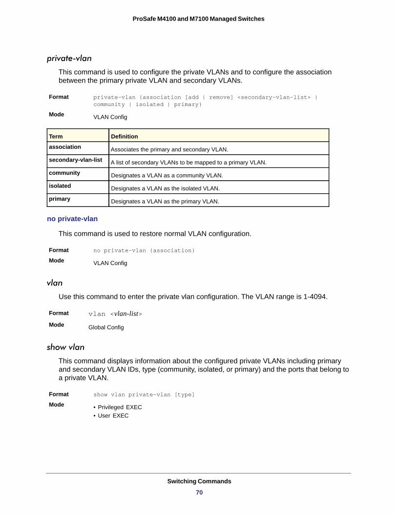
ProSafe M4100 and M7100 Managed Switches
private-vlan
This command is used to configure the private VLANs and to configure the association between the primary private VLAN and secondary VLANs.
Format private-vlan {association [add | remove] <secondary-vlan-list> | community | isolated | primary}
Mode
association
secondary-vlan-list
community
isolated
primary
no private-vlan
This command is used to restore normal VLAN configuration.
Format no private-vlan {association}
Mode
vlan
Use this command to enter the private vlan configuration. The VLAN range is 1-4094.
Format vlan <vlan-list>Mode
show vlan
This command displays information about the configured private VLANs including primary and secondary VLAN IDs, type (community, isolated, or primary) and the ports that belong to a private VLAN.
Format show vlan private-vlan [type]
Mode • Privileged EXEC• User EXEC
VLAN Config
Term Definition
Associates the primary and secondary VLAN.
A list of secondary VLANs to be mapped to a primary VLAN.
Designates a VLAN as a community VLAN.
Designates a VLAN as the isolated VLAN.
Designates a VLAN as the primary VLAN.
VLAN Config
Global Config
Switching Commands
70
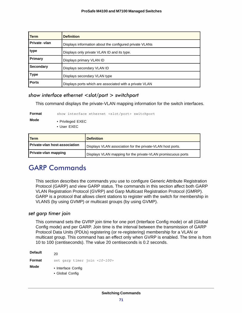
ProSafe M4100 and M7100 Managed Switches
Private -vlan
type
Primary
Secondary
Type
Ports
show interface ethernet <slot/port > switchport
This command displays the private-VLAN mapping information for the switch interfaces.
Format show interface ethernet <slot/port> switchport
Mode • Privileged EXEC• User EXEC
Private-vlan host-association
Private-vlan mapping
GARP Commands
This section describes the commands you use to configure Generic Attribute Registration Protocol (GARP) and view GARP status. The commands in this section affect both GARP VLAN Registration Protocol (GVRP) and Garp Multicast Registration Protocol (GMRP). GARP is a protocol that allows client stations to register with the switch for membership in VLANS (by using GVMP) or multicast groups (by using GVMP).
set garp timer join
This command sets the GVRP join time for one port (Interface Config mode) or all (Global Config mode) and per GARP. Join time is the interval between the transmission of GARP Protocol Data Units (PDUs) registering (or re-registering) membership for a VLAN or multicast group. This command has an effect only when GVRP is enabled. The time is from 10 to 100 (centiseconds). The value 20 centiseconds is 0.2 seconds.
Default
Format set garp timer join <10-100>
Mode • Interface Config• Global Config
Term Definition
Displays information about the configured private VLANs
Displays only private VLAN ID and its type.
Displays primary VLAN ID
Displays secondary VLAN ID
Displays secondary VLAN type
Displays ports which are associated with a private VLAN
Term Definition
Displays VLAN association for the private-VLAN host ports.
Displays VLAN mapping for the private-VLAN promiscuous ports
20
Switching Commands
71
ProSafe M4100 and M7100 Managed Switches
no set garp timer join
This command sets the GVRP join time (for one or all ports and per GARP) to the default and only has an effect when GVRP is enabled.
Format no set garp timer join
Mode • Interface Config• Global Config
set garp timer leave
This command sets the GVRP leave time for one port (Interface Config mode) or all ports (Global Config mode) and only has an effect when GVRP is enabled. Leave time is the time to wait after receiving an unregister request for a VLAN or a multicast group before deleting the VLAN entry. This can be considered a buffer time for another station to assert registration for the same attribute in order to maintain uninterrupted service. The leave time is 20–600 (centiseconds). The value 60 centiseconds is 0.6 seconds.
Default
Format set garp timer leave <20-600>
Mode • Interface Config• Global Config
no set garp timer leave
This command sets the GVRP leave time on all ports or a single port to the default and only has an effect when GVRP is enabled.
Format no set garp timer leave
Mode • Interface Config• Global Config
set garp timer leaveall
This command sets how frequently Leave All PDUs are generated. A Leave All PDU indicates that all registrations will be unregistered. Participants would need to rejoin in order to maintain registration. The value applies per port and per GARP participation. The time may range from 200 to 6000 (centiseconds). The value 1000 centiseconds is 10 seconds. You can use this command on all ports (Global Config mode) or a single port (Interface Config mode), and it only has an effect only when GVRP is enabled.
Default
Format set garp timer leaveall <200-6000>
Mode • Interface Config• Global Config
60
1000
Switching Commands
72
ProSafe M4100 and M7100 Managed Switches
no set garp timer leaveall
This command sets how frequently Leave All PDUs are generated the default and only has an effect when GVRP is enabled.
Format no set garp timer leaveall
Mode • Interface Config• Global Config
show garp
This command displays GARP information.
Format show garp
Mode • Privileged EXEC• User EXEC
GMRP Admin Mode
GVRP Admin Mode
GVRP Commands
This section describes the commands you use to configure and view GARP VLAN Registration Protocol (GVRP) information. GVRP-enabled switches exchange VLAN configuration information, which allows GVRP to provide dynamic VLAN creation on trunk ports and automatic VLAN pruning.
Note: If GVRP is disabled, the system does not forward GVRP messages.
set gvrp adminmode
This command enables GVRP on the system.
Default
Format set gvrp adminmode
Mode
Term Definition
The administrative mode of GARP Multicast Registration Protocol (GMRP) for the system.
The administrative mode of GARP VLAN Registration Protocol (GVRP) for the system.
disabled
Privileged EXEC
Switching Commands
73
ProSafe M4100 and M7100 Managed Switches
no set gvrp adminmode
This command disables GVRP.
Format no set gvrp adminmode
Mode
set gvrp interfacemode
This command enables GVRP on a single port (Interface Config mode) or all ports (Global Config mode).
Default
Format set gvrp interfacemode
Mode • Interface Config• Global Config
no set gvrp interfacemode
This command disables GVRP on a single port (Interface Config mode) or all ports (Global Config mode). If GVRP is disabled, Join Time, Leave Time, and Leave All Time have no effect.
Format no set gvrp interfacemode
Mode • Interface Config• Global Config
show gvrp configuration
This command displays Generic Attributes Registration Protocol (GARP) information for one or all interfaces.
Format show gvrp configuration {<slot/port> | all}
Mode • Privileged EXEC• User EXEC
Privileged EXEC
disabled
Term Definition
Interface Valid slot and port number separated by forward slashes.
Join Timer The interval between the transmission of GARP PDUs registering (or re-registering) membership for an attribute. Current attributes are a VLAN or multicast group. There is an instance of this timer on a per-Port, per-GARP participant basis. Permissible values are 10–100 centiseconds (0.1 to 1.0 seconds). The factory default is 20 centiseconds (0.2 seconds). The finest granularity of specification is one centisecond (0.01 seconds).
Switching Commands
74
ProSafe M4100 and M7100 Managed Switches
GMRP Commands
This section describes the commands you use to configure and view GARP Multicast Registration Protocol (GMRP) information. Like IGMP snooping, GMRP helps control the flooding of multicast packets. GMRP-enabled switches dynamically register and deregister group membership information with the MAC networking devices attached to the same segment. GMRP also allows group membership information to propagate across all networking devices in the bridged LAN that support Extended Filtering Services.
Note: If GMRP is disabled, the system does not forward GMRP messages.
set gmrp adminmode
This command enables GARP Multicast Registration Protocol (GMRP) on the system.
Default
Format set gmrp adminmode
Mode
no set gmrp adminmode
This command disables GARP Multicast Registration Protocol (GMRP) on the system.
Format no set gmrp adminmode
Mode
Leave Timer The period of time to wait after receiving an unregister request for an attribute before deleting the attribute. Current attributes are a VLAN or multicast group. This may be considered a buffer time for another station to assert registration for the same attribute in order to maintain uninterrupted service. There is an instance of this timer on a per-Port, per-GARP participant basis. Permissible values are 20–600 centiseconds (0.2 to 6.0 seconds). The factory default is 60 centiseconds (0.6 seconds).
LeaveAll Timer This Leave All Time controls how frequently LeaveAll PDUs are generated. A LeaveAll PDU indicates that all registrations will shortly be deregistered. Participants will need to rejoin in order to maintain registration. There is an instance of this timer on a per-Port, per-GARP participant basis. The Leave All Period Timer is set to a random value in the range of LeaveAllTime to 1.5*LeaveAllTime. Permissible values are 200–6000 centiseconds (2–60 seconds). The factory default is 1000 centiseconds (10 seconds).
Port GVMRP Mode The GVRP administrative mode for the port, which is enabled or disabled (default). If this
parameter is disabled, Join Time, Leave Time, and Leave All Time have no effect.
disabled
Privileged EXEC
Privileged EXEC
Term Definition
Switching Commands
75
ProSafe M4100 and M7100 Managed Switches
set gmrp interfacemode
This command enables GARP Multicast Registration Protocol on a single interface (Interface Config mode) or all interfaces (Global Config mode). If an interface which has GARP enabled is enabled for routing or is enlisted as a member of a port-channel (LAG), GARP functionality is disabled on that interface. GARP functionality is subsequently re-enabled if routing is disabled and port-channel (LAG) membership is removed from an interface that has GARP enabled.
Default
Format set gmrp interfacemode
Mode • Interface Config• Global Config
no set gmrp interfacemode
This command disables GARP Multicast Registration Protocol on a single interface or all interfaces. If an interface which has GARP enabled is enabled for routing or is enlisted as a member of a port-channel (LAG), GARP functionality is disabled. GARP functionality is subsequently re-enabled if routing is disabled and port-channel (LAG) membership is removed from an interface that has GARP enabled.
Format no set gmrp interfacemode
Mode • Interface Config• Global Config
show gmrp configuration
This command displays Generic Attributes Registration Protocol (GARP) information for one or all interfaces.
Format show gmrp configuration {<slot/port> | all}
Mode • Privileged EXEC• User EXEC
disabled
Term Definition
Interface The slot/port of the interface that this row in the table describes.
Join Timer The interval between the transmission of GARP PDUs registering (or re-registering) membership for an attribute. Current attributes are a VLAN or multicast group. There is an instance of this timer on a per-Port, per-GARP participant basis. Permissible values are 10–100 centiseconds (0.1 to 1.0 seconds). The factory default is 20 centiseconds (0.2 seconds). The finest granularity of specification is 1 centisecond (0.01 seconds).
Switching Commands
76
ProSafe M4100 and M7100 Managed Switches
show mac-address-table gmrp
This command displays the GMRP entries in the Multicast Forwarding Database (MFDB) table.
Format show mac-address-table gmrp
Mode
Mac Address
Type
Description
Interfaces
Port-Based Network Access Control Commands
This section describes the commands you use to configure port-based network access control (802.1x). Port-based network access control allows you to permit access to network services only to and devices that are authorized and authenticated.
Leave Timer The period of time to wait after receiving an unregister request for an attribute before deleting the attribute. Current attributes are a VLAN or multicast group. This may be considered a buffer time for another station to assert registration for the same attribute in order to maintain uninterrupted service. There is an instance of this timer on a per-Port, per-GARP participant basis. Permissible values are 20–600 centiseconds (0.2 to 6.0 seconds). The factory default is 60 centiseconds (0.6 seconds).
LeaveAll Timer This Leave All Time controls how frequently LeaveAll PDUs are generated. A LeaveAll PDU indicates that all registrations will shortly be deregistered. Participants will need to rejoin in order to maintain registration. There is an instance of this timer on a per-Port, per-GARP participant basis. The Leave All Period Timer is set to a random value in the range of LeaveAllTime to 1.5*LeaveAllTime. Permissible values are 200–6000 centiseconds (2–60 seconds). The factory default is 1000 centiseconds (10 seconds).
Port GMRP Mode The GMRP administrative mode for the port. It may be enabled or disabled. If this
parameter is disabled, Join Time, Leave Time, and Leave All Time have no effect.
Privileged EXEC
Term Definition
A unicast MAC address for which the switch has forwarding and or filtering information. The format is 6 or 8 two-digit hexadecimal numbers that are separated by colons, for example 01:23:45:67:89:AB. In an IVL system the MAC address is displayed as 8 bytes.
The type of the entry. Static entries are those that are configured by the end user. Dynamic entries are added to the table as a result of a learning process or protocol.
The text description of this multicast table entry.
The list of interfaces that are designated for forwarding (Fwd:) and filtering (Flt:).
Term Definition
Switching Commands
77
ProSafe M4100 and M7100 Managed Switches
clear dot1x statistics
This command resets the 802.1x statistics for the specified port or for all ports.
Format clear dot1x statistics {<slot/port> | all}Mode
clear radius statistics
This command is used to clear all RADIUS statistics.
Format clear radius statistics
Mode
dot1x eapolflood
Use this command to enable EAPOL flood support on the switch.
Format
Mode
Default
no dot1x eapolflood
This command disables EAPOL flooding on the switch.
Format no dot1x eapolflood
Mode
dot1x guest-vlan
This command configures VLAN as guest vlan on a per port basis. The command specifies an active VLAN as an IEEE 802.1x guest VLAN. The range is 1 to the maximum VLAN ID supported by the platform.
Default
Format dot1x guest-vlan <vlan-id>
Mode
Privileged EXEC
Privileged EXEC
dot1x eapolflood
Global Config
Disabled
Global Config
disabled
Interface Config
Switching Commands
78
ProSafe M4100 and M7100 Managed Switches
no dot1x guest-vlan
This command disables Guest VLAN on the interface.
Default
Format no dot1x guest-vlan
Mode
dot1x initialize
This command begins the initialization sequence on the specified port. This command is only valid if the control mode for the specified port is “auto” or “mac-based”. If the control mode is not 'auto' or “mac-based”, an error will be returned.
Format dot1x initialize <slot/port>Mode
dot1x mac-auth-bypass
This command enables MAC-Based Authentication Bypass (MAB) for 802.1x-unaware clients. MAB provides 802.1x-unaware clients controlled access to the network using the devices’ MAC address as an identifier. This requires that the known and allowable MAC address and corresponding access rights be pre-populated in the authentication server. MAB works only when the port control mode of the port is MAC-based.
Format dot1x mac-auth-bypass
Mode
no dot1x mac-auth-bypass
This command disables MAB for 802.1x-unaware clients.
Format no dot1x mac-auth-bypass
Mode
dot1x max-req
This command sets the maximum number of times the authenticator state machine on this port will transmit an EAPOL EAP Request/Identity frame before timing out the supplicant. The <count> value must be in the range 1 - 10.
Default
Format dot1x max-req <count>Mode
disabled
Interface Config
Privileged EXEC
Interface Config
Interface Config
2
Interface Config
Switching Commands
79
ProSafe M4100 and M7100 Managed Switches
no dot1x max-req
This command sets the maximum number of times the authenticator state machine on this port will transmit an EAPOL EAP Request/Identity frame before timing out the supplicant.
Format no dot1x max-req
Mode
dot1x max-users
Use this command to set the maximum number of clients supported on the port when MAC-based dot1x authentication is enabled on the port. The maximum users supported per port is dependent on the product. The <count> value is in the range 1 - 48.
Default
Format dot1x max-users <count>Mode
no dot1x max-users
This command resets the maximum number of clients allowed per port to its default value.
Format no dot1x max-req
Mode
dot1x port-control
This command sets the authentication mode to use on the specified port. Select force-unauthorized to specify that the authenticator PAE unconditionally sets the controlled port to unauthorized. Select force-authorized to specify that the authenticator PAE unconditionally sets the controlled port to authorized. Select auto to specify that the authenticator PAE sets the controlled port mode to reflect the outcome of the authentication exchanges between the supplicant, authenticator, and the authentication server. If the mac-based option is specified, MAC-based dot1x authentication is enabled on the port.
Default
Format dot1x port-control {force-unauthorized | force-authorized | auto | mac-based}
Mode
Interface Config
48
Interface Config
Interface Config
auto
Interface Config
Switching Commands
80
ProSafe M4100 and M7100 Managed Switches
no dot1x port-control
This command sets the 802.1x port control mode on the specified port to the default value.
Format no dot1x port-control
Mode
dot1x port-control all
This command sets the authentication mode to use on all ports. Select force-unauthorized to specify that the authenticator PAE unconditionally sets the controlled port to unauthorized. Select force-authorized to specify that the authenticator PAE unconditionally sets the controlled port to authorized. Select auto to specify that the authenticator PAE sets the controlled port mode to reflect the outcome of the authentication exchanges between the supplicant, authenticator, and the authentication server. If the mac-based option is specified, MAC-based dot1x authentication is enabled on the port.
Default
Format dot1x port-control all {force-unauthorized | force-authorized | auto | mac-based}
Mode
no dot1x port-control all
This command sets the authentication mode on all ports to the default value.
Format no dot1x port-control all
Mode
dot1x re-authenticate
This command begins the re-authentication sequence on the specified port. This command is only valid if the control mode for the specified port is “auto” or “mac-based”. If the control mode is not “auto” or “mac-based”, an error will be returned.
Format dot1x re-authenticate <slot/port>
Mode
dot1x re-authentication
This command enables re-authentication of the supplicant for the specified port.
Default
Format dot1x re-authentication
Mode
Interface Config
auto
Global Config
Global Config
Privileged EXEC
disabled
Interface Config
Switching Commands
81
ProSafe M4100 and M7100 Managed Switches
no dot1x re-authentication
This command disables re-authentication of the supplicant for the specified port.
Format no dot1x re-authentication
Mode
dot1x system-auth-control
Use this command to enable the dot1x authentication support on the switch. While disabled, the dot1x configuration is retained and can be changed, but is not activated.
Default
Format dot1x system-auth-control
Mode
no dot1x system-auth-control
This command is used to disable the dot1x authentication support on the switch.
Format no dot1x system-auth-control
Mode
dot1x timeout
This command sets the value, in seconds, of the timer used by the authenticator state machine on this port. Depending on the token used and the value (in seconds) passed, various timeout configurable parameters are set. The following tokens are supported:
Interface Config
disabled
Global Config
Global Config
Tokens Definition
guest-vlan-period The time, in seconds, for which the authenticator waits to see if any EAPOL packets are received on a port before authorizing the port and placing the port in the guest vlan (if configured). The guest vlan timer is only relevant when guest vlan has been configured on that specific port.
reauth-period The value, in seconds, of the timer used by the authenticator state machine on this port to determine when re-authentication of the supplicant takes place. The reauth-period must be a value in the range 1 - 65535.
quiet-period The value, in seconds, of the timer used by the authenticator state machine on this port to define periods of time in which it will not attempt to acquire a supplicant. The quiet-period must be a value in the range 0 - 65535.
tx-period The value, in seconds, of the timer used by the authenticator state machine on this port to determine when to send an EAPOL EAP Request/Identity frame to the supplicant. The quiet-period must be a value in the range 1 - 65535.
Switching Commands
82
ProSafe M4100 and M7100 Managed Switches
no dot1x timeout
This command sets the value, in seconds, of the timer used by the authenticator state machine on this port to the default values. Depending on the token used, the corresponding default values are set.
Format no dot1x timeout {guest-vlan-period | reauth-period | quiet-period | tx-period | supp-timeout | server-timeout}
Mode
dot1x unauthenticated-vlan
Use this command to configure the unauthenticated VLAN associated with that port. The unauthenticated VLAN ID can be a valid VLAN ID from 0-Maximum supported VLAN ID (4093 for 7000 series). The unauthenticated VLAN must be statically configured in the VLAN database to be operational. By default, the unauthenticated VLAN is 0, i.e. invalid and not operational.
Default
Format dot1x unauthenticated-vlan <vlan id>
Mode
supp-timeout The value, in seconds, of the timer used by the authenticator state machine on this port to timeout the supplicant. The supp-timeout must be a value in the range 1 - 65535.
server-timeout
Default • guest-vlan-period: 90 seconds• reauth-period: 3600 seconds• quiet-period: 60 seconds• tx-period: 30 seconds• supp-timeout: 30 seconds• server-timeout: 30 seconds
Format dot1x timeout {{guest-vlan-period <seconds>} |{reauth-period <seconds>} | {quiet-period <seconds>} | {tx-period <seconds>} | {supp-timeout <seconds>} | {server-timeout <seconds>}}
Mode
The value, in seconds, of the timer used by the authenticator state machine on this port to timeout the authentication server. The supp-timeout must be a value in the range 1 - 65535.
Interface Config
Interface Config
0
Interface Config
Tokens Definition
Switching Commands
83
ProSafe M4100 and M7100 Managed Switches
no dot1x unauthenticated-vlan
This command resets the unauthenticated-vlan associated with the port to its default value.
Format no dot1x unauthenticated-vlan
Mode
dot1x user
This command adds the specified user to the list of users with access to the specified port or all ports. The <user> parameter must be a configured user.
Format dot1x user <user> {<slot/port> | all}
Mode
no dot1x user
This command removes the user from the list of users with access to the specified port or all ports.
Format no dot1x user <user> {<slot/port> | all}
Mode
clear dot1x authentication-history
This command clears the authentication history table captured during successful and unsuccessful authentication on all interface or the specified interface.
Format clear dot1x authentication-history [slot/port]
Mode
dot1x dynamic-vlan enable
Use this command to enable the switch to create VLANs dynamically when a RADIUS assigned VLAN does not exist in the switch.
Format dot1x dynamic-vlan enable
Mode
Default
Interface Config
Global Config
Global Config
Global Config
Global Config
Disabled
Switching Commands
84
ProSafe M4100 and M7100 Managed Switches
no dot1x dynamic-vlan enable
Use this command to disable the switch from creating VLANs dynamically when a RADIUS assigned VLAN does not exist in the switch.
Format no dot1x dynamic-vlan enable
Mode
dot1x system-auth-control monitor
Use this command to enable the 802.1X monitor mode on the switch. The purpose of Monitor mode is to help troubleshoot port-based authentication configuration issues without disrupting network access for hosts connected to the switch. In Monitor mode, a host is granted network access to an 802.1X-enabled port even if it fails the authentication process. The results of the process are logged for diagnostic purposes.
Format dot1x system-auth-control monitor
Mode
Default
no dot1x system-auth-control monitor
Use this command to disable the 802.1X monitor on the switch.
Format no dot1x system-auth-control monitor
Mode
show dot1x authentication-history
This command displays 802.1X authentication events and information during successful and unsuccessful Dot1x authentication process for all interfaces or the specified interface. Use the optional keywords to display only failure authentication events in summary or in detail.
Format show dot1x authentication-history {slot/port | all} [failedauth-only] [detail]
Mode
Global Config
Global Config
Disabled
Global Config
Privileged EXEC
Term Definition
Time Stamp The exact time at which the event occurs.
Interface Physical Port on which the event occurs.
Mac-Address The supplicant/client MAC address.
VLAN assigned The VLAN assigned to the client/port on authentication.
Switching Commands
85
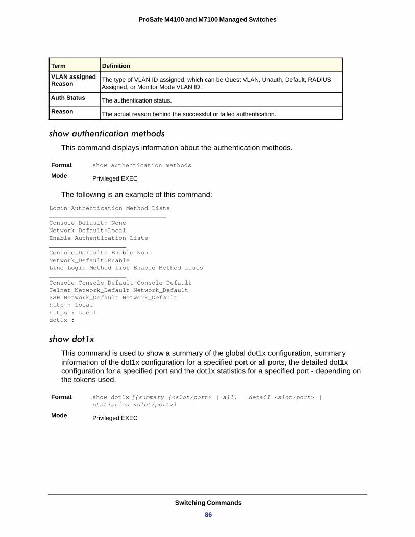
ProSafe M4100 and M7100 Managed Switches
show authentication methods
This command displays information about the authentication methods.
Format show authentication methods
Mode
The following is an example of this command:
Login Authentication Method Lists________________________________Console_Default: NoneNetwork_Default:LocalEnable Authentication Lists_____________________Console_Default: Enable NoneNetwork_Default:EnableLine Login Method List Enable Method Lists_____________________Console Console_Default Console_DefaultTelnet Network_Default Network_DefaultSSH Network_Default Network_Defaulthttp : Localhttps : Localdot1x :
show dot1x
This command is used to show a summary of the global dot1x configuration, summary information of the dot1x configuration for a specified port or all ports, the detailed dot1x configuration for a specified port and the dot1x statistics for a specified port - depending on the tokens used.
Format show dot1x [{summary {<slot/port> | all} | detail <slot/port> | statistics <slot/port>]
Mode
VLAN assigned Reason The type of VLAN ID assigned, which can be Guest VLAN, Unauth, Default, RADIUS
Assigned, or Monitor Mode VLAN ID.
Auth Status The authentication status.
Reason The actual reason behind the successful or failed authentication.
Privileged EXEC
Privileged EXEC
Term Definition
Switching Commands
86
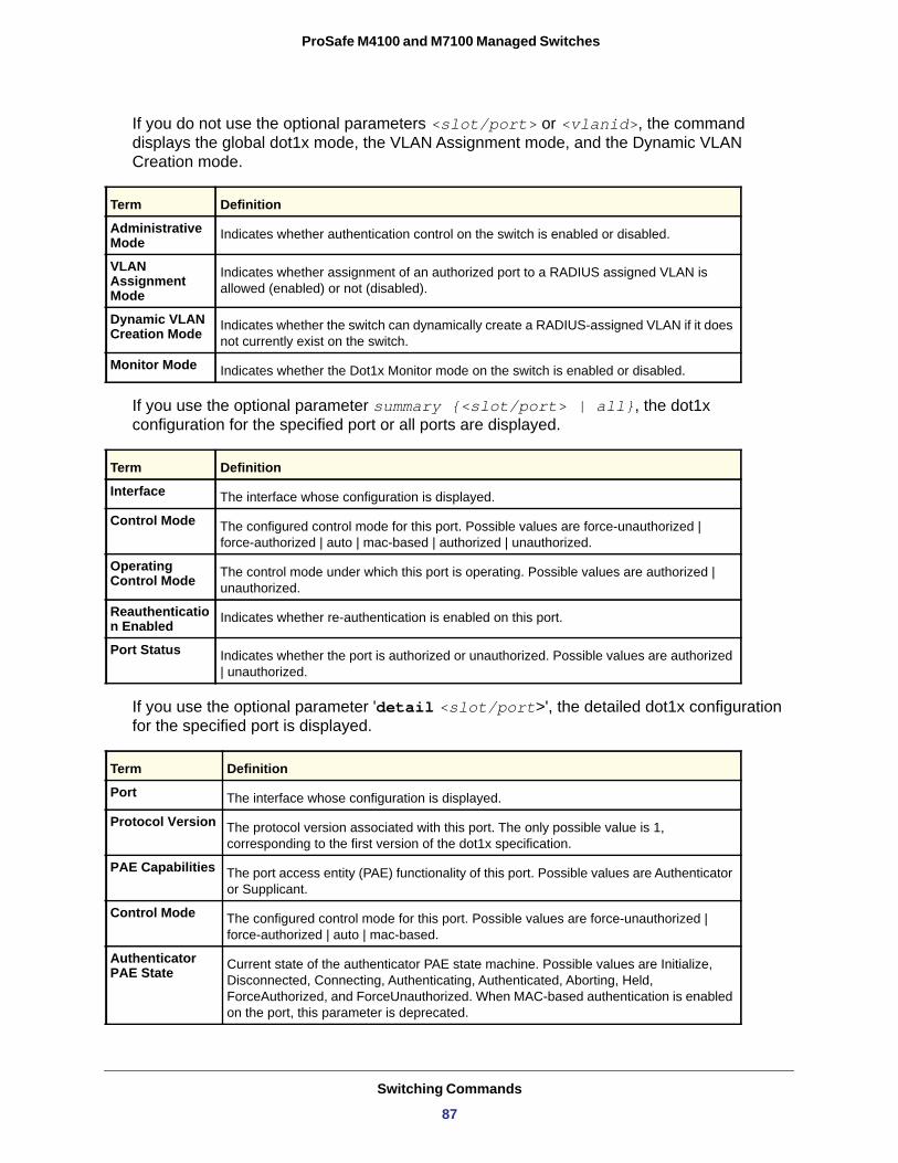
ProSafe M4100 and M7100 Managed Switches
If you do not use the optional parameters <slot/port> or <vlanid>, the command displays the global dot1x mode, the VLAN Assignment mode, and the Dynamic VLAN Creation mode.
Administrative Mode
VLAN Assignment Mode
Dynamic VLAN Creation Mode
Monitor Mode
If you use the optional parameter summary {<slot/port> | all}, the dot1x configuration for the specified port or all ports are displayed.
Interface
Control Mode
Operating Control Mode
Reauthentication Enabled
Port Status
If you use the optional parameter 'detail <slot/port>', the detailed dot1x configuration for the specified port is displayed.
Term Definition
Indicates whether authentication control on the switch is enabled or disabled.
Indicates whether assignment of an authorized port to a RADIUS assigned VLAN is allowed (enabled) or not (disabled).
Indicates whether the switch can dynamically create a RADIUS-assigned VLAN if it does not currently exist on the switch.
Indicates whether the Dot1x Monitor mode on the switch is enabled or disabled.
Term Definition
The interface whose configuration is displayed.
The configured control mode for this port. Possible values are force-unauthorized | force-authorized | auto | mac-based | authorized | unauthorized.
The control mode under which this port is operating. Possible values are authorized | unauthorized.
Indicates whether re-authentication is enabled on this port.
Indicates whether the port is authorized or unauthorized. Possible values are authorized | unauthorized.
Term Definition
Port The interface whose configuration is displayed.
Protocol Version The protocol version associated with this port. The only possible value is 1, corresponding to the first version of the dot1x specification.
PAE Capabilities The port access entity (PAE) functionality of this port. Possible values are Authenticator or Supplicant.
Control Mode The configured control mode for this port. Possible values are force-unauthorized | force-authorized | auto | mac-based.
Authenticator PAE State Current state of the authenticator PAE state machine. Possible values are Initialize,
Disconnected, Connecting, Authenticating, Authenticated, Aborting, Held, ForceAuthorized, and ForceUnauthorized. When MAC-based authentication is enabled on the port, this parameter is deprecated.
Switching Commands
87
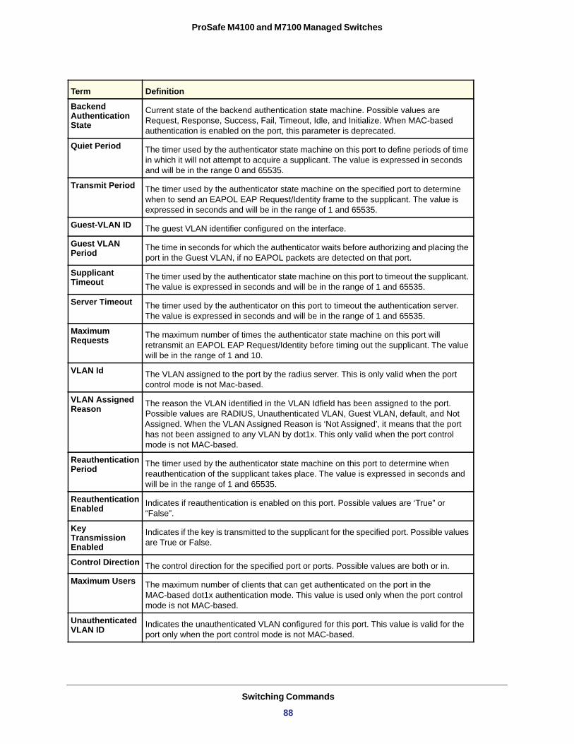
ProSafe M4100 and M7100 Managed Switches
Backend Authentication State
Current state of the backend authentication state machine. Possible values are Request, Response, Success, Fail, Timeout, Idle, and Initialize. When MAC-based authentication is enabled on the port, this parameter is deprecated.
Quiet Period The timer used by the authenticator state machine on this port to define periods of time in which it will not attempt to acquire a supplicant. The value is expressed in seconds and will be in the range 0 and 65535.
Transmit Period The timer used by the authenticator state machine on the specified port to determine when to send an EAPOL EAP Request/Identity frame to the supplicant. The value is expressed in seconds and will be in the range of 1 and 65535.
Guest-VLAN ID The guest VLAN identifier configured on the interface.
Guest VLAN Period The time in seconds for which the authenticator waits before authorizing and placing the
port in the Guest VLAN, if no EAPOL packets are detected on that port.
Supplicant Timeout The timer used by the authenticator state machine on this port to timeout the supplicant.
The value is expressed in seconds and will be in the range of 1 and 65535.
Server Timeout The timer used by the authenticator on this port to timeout the authentication server. The value is expressed in seconds and will be in the range of 1 and 65535.
Maximum Requests The maximum number of times the authenticator state machine on this port will
retransmit an EAPOL EAP Request/Identity before timing out the supplicant. The value will be in the range of 1 and 10.
VLAN Id The VLAN assigned to the port by the radius server. This is only valid when the port control mode is not Mac-based.
VLAN Assigned Reason The reason the VLAN identified in the VLAN Idfield has been assigned to the port.
Possible values are RADIUS, Unauthenticated VLAN, Guest VLAN, default, and Not Assigned. When the VLAN Assigned Reason is ‘Not Assigned’, it means that the port has not been assigned to any VLAN by dot1x. This only valid when the port control mode is not MAC-based.
Reauthentication Period The timer used by the authenticator state machine on this port to determine when
reauthentication of the supplicant takes place. The value is expressed in seconds and will be in the range of 1 and 65535.
Reauthentication Enabled Indicates if reauthentication is enabled on this port. Possible values are ‘True” or
“False”.
Key Transmission Enabled
Indicates if the key is transmitted to the supplicant for the specified port. Possible values are True or False.
Control Direction The control direction for the specified port or ports. Possible values are both or in.
Maximum Users The maximum number of clients that can get authenticated on the port in the MAC-based dot1x authentication mode. This value is used only when the port control mode is not MAC-based.
Unauthenticated VLAN ID Indicates the unauthenticated VLAN configured for this port. This value is valid for the
port only when the port control mode is not MAC-based.
Term Definition
Switching Commands
88
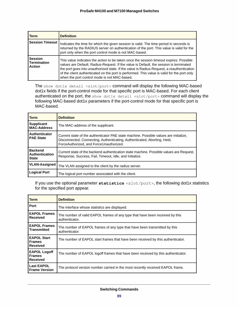
ProSafe M4100 and M7100 Managed Switches
The show dot1x detail <slot/port> command will display the following MAC-based dot1x fields if the port-control mode for that specific port is MAC-based. For each client authenticated on the port, the show dot1x detail <slot/port> command will display the following MAC-based dot1x parameters if the port-control mode for that specific port is MAC-based.
Supplicant MAC-Address
Authenticator PAE State
Backend Authentication State
VLAN-Assigned
Logical Port
If you use the optional parameter statistics <slot/port>, the following dot1x statistics for the specified port appear.
Session Timeout Indicates the time for which the given session is valid. The time period in seconds is returned by the RADIUS server on authentication of the port. This value is valid for the port only when the port control mode is not MAC-based.
Session Termination Action
This value indicates the action to be taken once the session timeout expires. Possible values are Default, Radius-Request. If the value is Default, the session is terminated the port goes into unauthorized state. If the value is Radius-Request, a reauthentication of the client authenticated on the port is performed. This value is valid for the port only when the port control mode is not MAC-based.
Term Definition
The MAC-address of the supplicant.
Current state of the authenticator PAE state machine. Possible values are Initialize, Disconnected, Connecting, Authenticating, Authenticated, Aborting, Held, ForceAuthorized, and ForceUnauthorized.
Current state of the backend authentication state machine. Possible values are Request, Response, Success, Fail, Timeout, Idle, and Initialize.
The VLAN assigned to the client by the radius server.
The logical port number associated with the client.
Term Definition
Port The interface whose statistics are displayed.
EAPOL Frames Received The number of valid EAPOL frames of any type that have been received by this
authenticator.
EAPOL Frames Transmitted The number of EAPOL frames of any type that have been transmitted by this
authenticator.
EAPOL Start Frames Received
The number of EAPOL start frames that have been received by this authenticator.
EAPOL Logoff Frames Received
The number of EAPOL logoff frames that have been received by this authenticator.
Last EAPOL Frame Version The protocol version number carried in the most recently received EAPOL frame.
Term Definition
Switching Commands
89
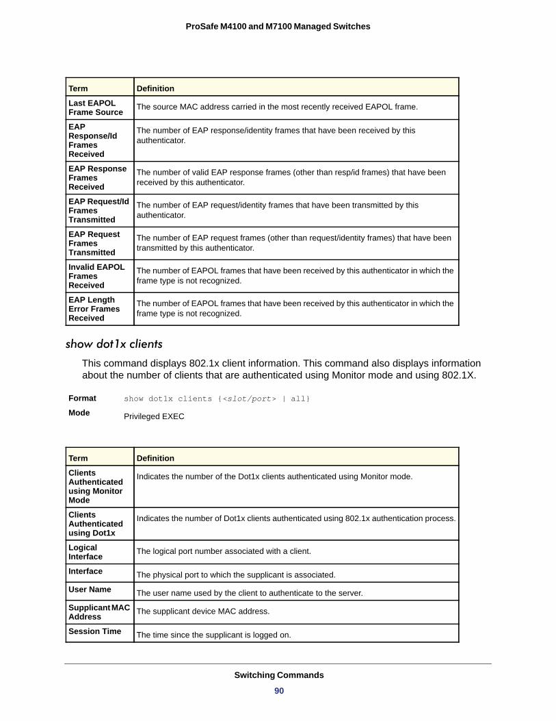
ProSafe M4100 and M7100 Managed Switches
show dot1x clients
This command displays 802.1x client information. This command also displays information about the number of clients that are authenticated using Monitor mode and using 802.1X.
Format show dot1x clients {<slot/port> | all}
Mode
Last EAPOL Frame Source The source MAC address carried in the most recently received EAPOL frame.
EAP Response/Id Frames Received
The number of EAP response/identity frames that have been received by this authenticator.
EAP Response Frames Received
The number of valid EAP response frames (other than resp/id frames) that have been received by this authenticator.
EAP Request/Id Frames Transmitted
The number of EAP request/identity frames that have been transmitted by this authenticator.
EAP Request Frames Transmitted
The number of EAP request frames (other than request/identity frames) that have been transmitted by this authenticator.
Invalid EAPOL Frames Received
The number of EAPOL frames that have been received by this authenticator in which the frame type is not recognized.
EAP Length Error Frames Received
The number of EAPOL frames that have been received by this authenticator in which the frame type is not recognized.
Privileged EXEC
Term Definition
Clients Authenticated using Monitor Mode
Indicates the number of the Dot1x clients authenticated using Monitor mode.
Clients Authenticated using Dot1x
Indicates the number of Dot1x clients authenticated using 802.1x authentication process.
Logical Interface The logical port number associated with a client.
Interface The physical port to which the supplicant is associated.
User Name The user name used by the client to authenticate to the server.
Supplicant MAC Address The supplicant device MAC address.
Session Time The time since the supplicant is logged on.
Term Definition
Switching Commands
90
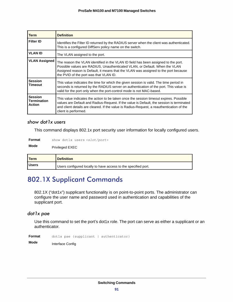
ProSafe M4100 and M7100 Managed Switches
show dot1x users
This command displays 802.1x port security user information for locally configured users.
Format show dot1x users <slot/port>Mode
Users
802.1X Supplicant Commands
802.1X (“dot1x”) supplicant functionality is on point-to-point ports. The administrator can configure the user name and password used in authentication and capabilities of the supplicant port.
dot1x pae
Use this command to set the port’s dot1x role. The port can serve as either a supplicant or an authenticator.
Format dot1x pae {supplicant | authenticator}
Mode
Filter ID Identifies the Filter ID returned by the RADIUS server when the client was authenticated. This is a configured DiffServ policy name on the switch.
VLAN ID The VLAN assigned to the port.
VLAN Assigned The reason the VLAN identified in the VLAN ID field has been assigned to the port. Possible values are RADIUS, Unauthenticated VLAN, or Default. When the VLAN Assigned reason is Default, it means that the VLAN was assigned to the port because the PVID of the port was that VLAN ID.
Session Timeout This value indicates the time for which the given session is valid. The time period in
seconds is returned by the RADIUS server on authentication of the port. This value is valid for the port only when the port-control mode is not MAC-based.
Session Termination Action
This value indicates the action to be taken once the session timeout expires. Possible values are Default and Radius-Request. If the value is Default, the session is terminated and client details are cleared. If the value is Radius-Request, a reauthentication of the client is performed.
Privileged EXEC
Term Definition
Users configured locally to have access to the specified port.
Interface Config
Term Definition
Switching Commands
91
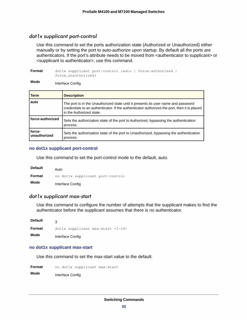
ProSafe M4100 and M7100 Managed Switches
dot1x supplicant port-control
Use this command to set the ports authorization state (Authorized or Unauthorized) either manually or by setting the port to auto-authorize upon startup. By default all the ports are authenticators. If the port’s attribute needs to be moved from <authenticator to supplicant> or <supplicant to authenticator>, use this command.
Format dot1x supplicant port-control {auto | force-authorized | force_unauthorized}
Mode
auto
force-authorized
force- unauthorized
no dot1x supplicant port-control
Use this command to set the port-control mode to the default, auto.
Default
Format no dot1x supplicant port-control
Mode
dot1x supplicant max-start
Use this command to configure the number of attempts that the supplicant makes to find the authenticator before the supplicant assumes that there is no authenticator.
Default
Format dot1x supplicant max-start <1-10>
Mode
no dot1x supplicant max-start
Use this command to set the max-start value to the default.
Format no dot1x supplicant max-start
Mode
Interface Config
Term Description
The port is in the Unauthorized state until it presents its user name and password credentials to an authenticator. If the authenticator authorizes the port, then it is placed in the Authorized state.
Sets the authorization state of the port to Authorized, bypassing the authentication process.
Sets the authorization state of the port to Unauthorized, bypassing the authentication process.
Auto
Interface Config
3
Interface Config
Interface Config
Switching Commands
92
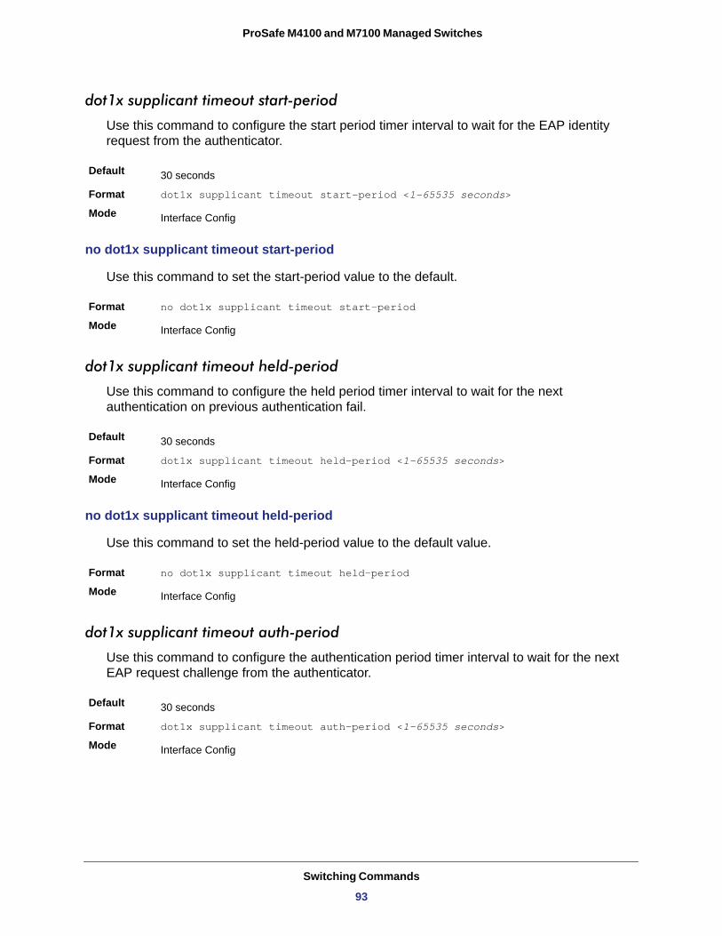
ProSafe M4100 and M7100 Managed Switches
dot1x supplicant timeout start-period
Use this command to configure the start period timer interval to wait for the EAP identity request from the authenticator.
Default
Format dot1x supplicant timeout start-period <1-65535 seconds>
Mode
no dot1x supplicant timeout start-period
Use this command to set the start-period value to the default.
Format no dot1x supplicant timeout start-period
Mode
dot1x supplicant timeout held-period
Use this command to configure the held period timer interval to wait for the next authentication on previous authentication fail.
Default
Format dot1x supplicant timeout held-period <1-65535 seconds>
Mode
no dot1x supplicant timeout held-period
Use this command to set the held-period value to the default value.
Format no dot1x supplicant timeout held-period
Mode
dot1x supplicant timeout auth-period
Use this command to configure the authentication period timer interval to wait for the next EAP request challenge from the authenticator.
Default
Format dot1x supplicant timeout auth-period <1-65535 seconds>
Mode
30 seconds
Interface Config
Interface Config
30 seconds
Interface Config
Interface Config
30 seconds
Interface Config
Switching Commands
93
ProSafe M4100 and M7100 Managed Switches
no dot1x supplicant timeout auth-period
Use this command to set the auth-period value to the default value.
Format no dot1x supplicant timeout auth-period
Mode
dot1x supplicant user
Use this command to map the given user to the port.
Format dot1x supplicant user
Mode
Storm-Control Commands
This section describes commands you use to configure storm-control and view storm-control configuration information. A traffic storm is a condition that occurs when incoming packets flood the LAN, which creates performance degradation in the network. The Storm-Control feature protects against this condition.
The 7000 series provides broadcast, multicast, and unicast story recovery for individual interfaces. Unicast Storm-Control protects against traffic whose MAC addresses are not known by the system. For broadcast, multicast, and unicast storm-control, if the rate of traffic ingressing on an interface increases beyond the configured threshold for that type, the traffic is dropped.
To configure storm-control, you will enable the feature for all interfaces or for individual interfaces, and you will set the threshold (storm-control level) beyond which the broadcast, multicast, or unicast traffic will be dropped. The Storm-Control feature allows you to limit the rate of specific types of packets through the switch on a per-port, per-type, basis.
Configuring a storm-control level also enables that form of storm-control. Disabling a storm-control level (using the “no” version of the command) sets the storm-control level back to the default value and disables that form of storm-control. Using the “no” version of the “storm-control” command (not stating a “level”) disables that form of storm-control but maintains the configured “level” (to be active the next time that form of storm-control is enabled.)
Note: The actual rate of ingress traffic required to activate storm-control is based on the size of incoming packets and the hard-coded average packet size of 512 bytes - used to calculate a packet-per-second (pps) rate - as the forwarding-plane requires pps versus an absolute
Interface Config
Interface Config
Switching Commands
94
ProSafe M4100 and M7100 Managed Switches
rate kbps. For example, if the configured limit is 10%, this is converted to ~25000 pps, and this pps limit is set in forwarding plane (hardware). You get the approximate desired output when 512bytes packets are used.
storm-control broadcast
Use this command to enable broadcast storm recovery mode for a specific interface. If the mode is enabled, broadcast storm recovery is active and, if the rate of L2 broadcast traffic ingressing on an interface increases beyond the configured threshold, the traffic will be dropped. Therefore, the rate of broadcast traffic will be limited to the configured threshold.
Default
Format storm-control broadcast
Mode
no storm-control broadcast
Use this command to disable broadcast storm recovery mode for a specific interface.
Format no storm-control broadcast
Mode
storm-control broadcast level
Use this command to configure the broadcast storm recovery threshold for an interface as a percentage of link speed and enable broadcast storm recovery. If the mode is enabled, broadcast storm recovery is active, and if the rate of L2 broadcast traffic ingressing on an interface increases beyond the configured threshold, the traffic is dropped. Therefore, the rate of broadcast traffic is limited to the configured threshold.
If the ‘shutdown’ option is selected, and the broadcast traffic increases beyond the threshold, the interface shuts down instead of dropping packets. To recover the port, issue ‘no shutdown’ under the port manually.
Default
Format storm-control broadcast level <0-100> {action [ratelimit | shutdown]}Mode
enabled
Interface Config
Interface Config
5
Interface Config
Switching Commands
95
ProSafe M4100 and M7100 Managed Switches
no storm-control broadcast level
This command sets the broadcast storm recovery threshold to the default value for an interface and disables broadcast storm recovery.
Format no storm-control broadcast level
Mode
storm-control broadcast rate
Use this command to configure the broadcast storm recovery threshold for an interface in packets per second. If the mode is enabled, broadcast storm recovery is active, and if the rate of L2 broadcast traffic ingressing on an interface increases beyond the configured threshold, the traffic is dropped. Therefore, the rate of broadcast traffic is limited to the configured threshold.
Default
Format storm-control broadcast rate <0-14880000>
Mode
no storm-control broadcast rate
This command sets the broadcast storm recovery threshold to the default value for an interface and disables broadcast storm recovery.
Format no storm-control broadcast rate
Mode
storm-control broadcast (Global)
This command enables broadcast storm recovery mode for all interfaces. If the mode is enabled, broadcast storm recovery is active, and if the rate of L2 broadcast traffic ingressing on an interface increases beyond the configured threshold, the traffic will be dropped. Therefore, the rate of broadcast traffic will be limited to the configured threshold.
Default
Format storm-control broadcast
Mode
no storm-control broadcast
This command disables broadcast storm recovery mode for all interfaces.
Format no storm-control broadcast
Mode
Interface Config
0
Interface Config
Interface Config
disabled
Global Config
Global Config
Switching Commands
96
ProSafe M4100 and M7100 Managed Switches
storm-control broadcast level (Global)
This command configures the broadcast storm recovery threshold for all interfaces as a percentage of link speed and enables broadcast storm recovery. If the mode is enabled, broadcast storm recovery is active, and if the rate of L2 broadcast traffic ingressing on an interface increases beyond the configured threshold, the traffic will be dropped. Therefore, the rate of broadcast traffic will be limited to the configured threshold. This command also enables broadcast storm recovery mode for all interfaces.
If the ‘shutdown’ option is selected, and the broadcast traffic increases beyond the threshold, the interface shuts down instead of dropping packets. To recover the port, issue ‘no shutdown’ under the port manually.
Default
Format storm-control broadcast level <0-100>Mode
no storm-control broadcast level
This command sets the broadcast storm recovery threshold to the default value for all interfaces and disables broadcast storm recovery.
Format no storm-control broadcast level
Mode
storm-control broadcast rate (Global)
Use this command to configure the broadcast storm recovery threshold for all interfaces in packets per second. If the mode is enabled, broadcast storm recovery is active, and if the rate of L2 broadcast traffic ingressing on an interface increases beyond the configured threshold, the traffic is dropped. Therefore, the rate of broadcast traffic is limited to the configured threshold.
Default
Format storm-control broadcast rate <0-14880000>
Mode
no storm-control broadcast rate
This command sets the broadcast storm recovery threshold to the default value for all interfaces and disables broadcast storm recovery.
Format no storm-control broadcast rate
Mode
5
Global Config
Global Config
0
Global Config
Global Config
Switching Commands
97
ProSafe M4100 and M7100 Managed Switches
storm-control multicast
This command enables multicast storm recovery mode for an interface. If the mode is enabled, multicast storm recovery is active, and if the rate of L2 multicast traffic ingressing on an interface increases beyond the configured threshold, the traffic will be dropped. Therefore, the rate of multicast traffic will be limited to the configured threshold.
Default
Format storm-control multicast
Mode
no storm-control multicast
This command disables multicast storm recovery mode for an interface.
Format no storm-control multicast
Mode
storm-control multicast level
This command configures the multicast storm recovery threshold for an interface as a percentage of link speed and enables multicast storm recovery mode. If the mode is enabled, multicast storm recovery is active, and if the rate of L2 multicast traffic ingressing on an interface increases beyond the configured threshold, the traffic will be dropped. Therefore, the rate of multicast traffic will be limited to the configured threshold.
Default
Format storm-control multicast level <0-100>
Mode
no storm-control multicast level
This command sets the multicast storm recovery threshold to the default value for an interface and disables multicast storm recovery.
Format no storm-control multicast level <0-100>
Mode
storm-control multicast rate
Use this command to configure the multicast storm recovery threshold for an interface in packets per second. If the mode is enabled, multicast storm recovery is active, and if the rate of L2 broadcast traffic ingressing on an interface increases beyond the configured threshold,
disabled
Interface Config
Interface Config
5
Interface Config
Interface Config
Switching Commands
98
ProSafe M4100 and M7100 Managed Switches
the traffic is dropped. Therefore, the rate of multicast traffic is limited to the configured threshold.
Default
Format storm-control multicast rate <0-14880000>
Mode
no storm-control multicast rate
This command sets the multicast storm recovery threshold to the default value for an interface and disables multicast storm recovery.
Format no storm-control multicast rate
Mode
storm-control multicast (Global)
This command enables multicast storm recovery mode for all interfaces. If the mode is enabled, multicast storm recovery is active, and if the rate of L2 multicast traffic ingressing on an interface increases beyond the configured threshold, the traffic will be dropped. Therefore, the rate of multicast traffic will be limited to the configured threshold.
Default
Format storm-control multicast
Mode
no storm-control multicast
This command disables multicast storm recovery mode for all interfaces.
Format no storm-control multicast
Mode
storm-control multicast level (Global)
This command configures the multicast storm recovery threshold for all interfaces as a percentage of link speed and enables multicast storm recovery mode. If the mode is enabled, multicast storm recovery is active, and if the rate of L2 multicast traffic ingressing on an interface increases beyond the configured threshold, the traffic will be dropped. Therefore, the rate of multicast traffic will be limited to the configured threshold.
Default
Format storm-control multicast level <0-100>Mode
0
Interface Config
Interface Config
disabled
Global Config
Global Config
5
Global Config
Switching Commands
99
ProSafe M4100 and M7100 Managed Switches
no storm-control multicast level
This command sets the multicast storm recovery threshold to the default value for all interfaces and disables multicast storm recovery.
Format no storm-control multicast level
Mode
storm-control multicast rate (Global)
Use this command to configure the multicast storm recovery threshold for all interfaces in packets per second. If the mode is enabled, multicast storm recovery is active, and if the rate of L2 broadcast traffic ingressing on an interface increases beyond the configured threshold, the traffic is dropped. Therefore, the rate of multicast traffic is limited to the configured threshold.
Default
Format storm-control multicast rate <0-14880000>
Mode
no storm-control broadcast rate
This command sets the broadcast storm recovery threshold to the default value for all interfaces and disables broadcast storm recovery.
Format no storm-control broadcast rate
Mode
storm-control unicast
This command enables unicast storm recovery mode for an interface. If the mode is enabled, unicast storm recovery is active, and if the rate of unknown L2 unicast (destination lookup failure) traffic ingressing on an interface increases beyond the configured threshold, the traffic will be dropped. Therefore, the rate of unknown unicast traffic will be limited to the configured threshold.
Default
Format storm-control unicast
Mode
Global Config
0
Global Config
Global Config
disabled
Interface Config
Switching Commands
100
ProSafe M4100 and M7100 Managed Switches
no storm-control unicast
This command disables unicast storm recovery mode for an interface.
Format no storm-control unicast
Mode
storm-control unicast level
This command configures the unicast storm recovery threshold for an interface as a percentage of link speed, and enables unicast storm recovery. If the mode is enabled, unicast storm recovery is active, and if the rate of unknown L2 unicast (destination lookup failure) traffic ingressing on an interface increases beyond the configured threshold, the traffic will be dropped. Therefore, the rate of unknown unicast traffic will be limited to the configured threshold. This command also enables unicast storm recovery mode for an interface.
Default
Format storm-control unicast level <0-100>
Mode
no storm-control unicast level
This command sets the unicast storm recovery threshold to the default value for an interface and disables unicast storm recovery.
Format no storm-control unicast level
Mode
storm-control unicast rate
Use this command to configure the unicast storm recovery threshold for an interface in packets per second. If the mode is enabled, unicast storm recovery is active, and if the rate of L2 broadcast traffic ingressing on an interface increases beyond the configured threshold, the traffic is dropped. Therefore, the rate of unicast traffic is limited to the configured threshold.
Default
Format storm-control unicast rate <0-14880000>
Mode
Interface Config
5
Interface Config
Interface Config
0
Interface Config
Switching Commands
101
ProSafe M4100 and M7100 Managed Switches
no storm-control unicast rate
This command sets the unicast storm recovery threshold to the default value for an interface and disables unicast storm recovery.
Format no storm-control unicast rate
Mode
storm-control unicast (Global)
This command enables unicast storm recovery mode for all interfaces. If the mode is enabled, unicast storm recovery is active, and if the rate of unknown L2 unicast (destination lookup failure) traffic ingressing on an interface increases beyond the configured threshold, the traffic will be dropped. Therefore, the rate of unknown unicast traffic will be limited to the configured threshold.
Default
Format storm-control unicast
Mode
no storm-control unicast
This command disables unicast storm recovery mode for all interfaces.
Format no storm-control unicast
Mode
storm-control unicast level (Global)
This command configures the unicast storm recovery threshold for all interfaces as a percentage of link speed, and enables unicast storm recovery. If the mode is enabled, unicast storm recovery is active, and if the rate of unknown L2 unicast (destination lookup failure) traffic ingressing on an interface increases beyond the configured threshold, the traffic will be dropped. Therefore, the rate of unknown unicast traffic will be limited to the configured threshold.
Default
Format storm-control unicast level <0-100>
Mode
Interface Config
disabled
Global Config
Global Config
5
Global Config
Switching Commands
102
ProSafe M4100 and M7100 Managed Switches
no storm-control unicast level
This command sets the unicast storm recovery threshold to the default value and disables unicast storm recovery for all interfaces.
Format no storm-control unicast level
Mode
storm-control unicast rate (Global)
Use this command to configure the unicast storm recovery threshold for all interfaces in packets per second. If the mode is enabled, unicast storm recovery is active, and if the rate of L2 broadcast traffic ingressing on an interface increases beyond the configured threshold, the traffic is dropped. Therefore, the rate of unicast traffic is limited to the configured threshold.
Default
Format storm-control unicast rate <0-14880000>
Mode
no storm-control unicast rate
This command sets the multicast storm recovery threshold to the default value for an interface and disables multicast storm recovery.
Format no storm-control unicast rate
Mode
show storm-control
This command displays switch configuration information. If you do not use any of the optional parameters, this command displays global storm control configuration parameters:
• Broadcast Storm Control Mode may be enabled or disabled. The factory default is disabled.
• Broadcast Storm Control Level The broadcast storm control level. The factory default is 5%.
• Multicast Storm Control Mode may be enabled or disabled. The factory default is disabled.
• Multicast Storm Control Level The multicast storm control level. The factory default is 5%.
• Unicast Storm Control Mode may be enabled or disabled. The factory default is disabled.
• Unicast Storm Control Level The unicast storm control level. The factory default is 5%.
Global Config
0
Global Config
Global Config
Switching Commands
103
ProSafe M4100 and M7100 Managed Switches
Use the all keyword to display the per-port configuration parameters for all interfaces, or specify the slot/port to display information about a specific interface.
Format show storm-control [all | <slot/port>]
Mode
Bcast Mode
Bcast Level
Mcast Mode
Mcast Level
Ucast Mode
Ucast Level
Flow Control Commands
In 802.3x flow control, the MAC control PAUSE operation is specified in IEEE 802.3 Annex 31 B. It allows traffic from one device to be throttled for a specified period of time and is defined for devices that are directly connected. A device that needs to inhibit transmission of data frames from another device on the LAN transmits a PAUSE frame as defined in the IEEE specification.
This feature allows the user to configure the switch to use symmetric, asymmetric, or no flow control. Asymmetric flow control allows the switch to respond to received PAUSE frames, but the port cannot generate PAUSE frames. Symmetric flow control allows the switch to both respond to and generate MAC control PAUSE frames.
flowcontrol {symmetric|asymmetric}
Use this command to enable or disable the symmetric or asymmetric flow control on the switch. Use the no form of command to disable the symmetric or asymmetric flow control. Asymmetric here means that Tx Pause can never be enabled. Only Rx Pause can be enabled.
Default
Format flowcontrol {symmetric|asymmetric}
Mode • Global Config• Interface Config
Privileged EXEC
Term Definition
Shows whether the broadcast storm control mode is enabled or disabled. The factory default is disabled.
The broadcast storm control level.
Shows whether the multicast storm control mode is enabled or disabled.
The multicast storm control level.
Shows whether the Unknown Unicast or DLF (Destination Lookup Failure) storm control mode is enabled or disabled.
The Unknown Unicast or DLF (Destination Lookup Failure) storm control level.
Disabled
Switching Commands
104
ProSafe M4100 and M7100 Managed Switches
no flowcontrol
Format no flowcontrol
Mode • Global Config• Interface Config
show flowcontrol
Use this command to display the IEEE 802.3 Annex 31B flow control settings and status for a specific interface or all interfaces. It also displays 802.3 Tx and Rx pause counts. Priority Flow Control frames counts are not displayed. If the port is enabled for priority flow control, operational flow control status is displayed as “Inactive”. Operational flow control status for stacking ports is always displayed as “N/A”.
Format show flowcontrol [slot/port]
Mode
Examples:
(switch)#show flowcontrol
Admin Flow Control: Symmetric
Port Flow Control RxPause TxPause Oper ------ ------------ -------- ---------0/1 Active 310 611 0/2 Inactive 0 0 (switch)#show flowcontrol interface 0/1
Admin Flow Control: Symmetric
Port Flow Control RxPause TxPause Oper --------- ------- -------- -------0/1 Active 310 611
Port-Channel/LAG (802.3ad) Commands
This section describes the commands you use to configure port-channels, which are also known as link aggregation groups (LAGs). Link aggregation allows you to combine multiple full-duplex Ethernet links into a single logical link. Network devices treat the aggregation as if it were a single link, which increases fault tolerance and provides load sharing. The LAG feature initially load shares traffic based upon the source and destination MAC address. Assign the port-channel (LAG) VLAN membership after you create a port-channel. If you do not assign VLAN membership, the port-channel might become a member of the management VLAN which can result in learning and switching issues.
Privileged Exec
Switching Commands
105
ProSafe M4100 and M7100 Managed Switches
A port-channel (LAG) interface can be either static or dynamic, but not both. All members of a port channel must participate in the same protocols.) A static port-channel interface does not require a partner system to be able to aggregate its member ports.
Note: If you configure the maximum number of dynamic port-channels (LAGs) that your platform supports, additional port-channels that you configure are automatically static.
addport
This command adds one port to the port-channel (LAG). The interface is a logical slot/port number or a group ID of a configured port-channel.
Note: Before adding a port to a port-channel, set the physical mode of the port. For more information, see speed on page 24.
deleteport (Interface Config)
This command deletes the port from the port-channel (LAG). The interface is a logical slot/port number or a group ID of a configured port-channel.
Format deleteport {<logical slot/port>|lag <lag-group-id>}
Mode
deleteport (Global Config)
This command deletes all configured ports from the port-channel (LAG). The interface is a logical slot/port number of a configured port-channel. To clear the port channels, see clear port-channel on page 549
Format deleteport <logical slot/port>
Mode
.
Format addport {<logical slot/port>|lag <lag-group-id>}
Mode Interface Config
Interface Config
Global Config
Switching Commands
106
ProSafe M4100 and M7100 Managed Switches
lacp admin key
Use this command to configure the administrative value of the key for the port-channel. The value range of <key> is 0–65535.
Default
Format lacp admin key <key>
Mode
Note: This command is only applicable to port-channel interfaces.
no lacp admin key
Use this command to configure the default administrative value of the key for the port-channel.
Format no lacp admin key
Mode
lacp collector max-delay
Use this command to configure the port-channel collector max delay. The valid range of <delay> is 0-65535.
Default
Format lacp collector max-delay <delay>
Mode
Note: This command is only applicable to port-channel interfaces.
no lacp collector max delay
Use this command to configure the default port-channel collector max delay.
Format no lacp collector max-delay
Mode
lacp actor admin
Use this command to configure the LACP actor admin parameters.
0x8000
Interface Config
Interface Config
0x8000
Interface Config
Interface Config
Switching Commands
107
ProSafe M4100 and M7100 Managed Switches
lacp actor admin key
Use this command to configure the administrative value of the LACP actor admin key. The valid range for <key> is 0-65535.
Default
Format lacp actor admin key <key>
Mode
Note: This command is only applicable to physical interfaces.
no lacp actor admin key
Use this command to configure the default administrative value of the key.
Format no lacp actor admin key
Mode
lacp actor admin state individual
Use this command to set LACP actor admin state to individual.
Format lacp actor admin state individual
Mode
Note: This command is only applicable to physical interfaces.
no lacp actor admin state individual
Use this command to set the LACP actor admin state to aggregation.
Format no lacp actor admin state individual
Mode
lacp actor admin state longtimeout
Use this command to set LACP actor admin state to longtimeout.
Format lacp actor admin state longtimeout
Mode
Internal Interface Number of this Physical Port
Interface Config
Interface Config
Interface Config
Interface Config
Interface Config
Switching Commands
108
ProSafe M4100 and M7100 Managed Switches
Note: This command is only applicable to physical interfaces.
no lacp actor admin state longtimeout
Use this command to set the LACP actor admin state to short timeout.
Format no lacp actor admin state longtimeout
Mode
Note: This command is only applicable to physical interfaces.
lacp actor admin state passive
Use this command to set the LACP actor admin state to passive.
Format lacp actor admin state passive
Mode
Note: This command is only applicable to physical interfaces.
no lacp actor admin state passive
Use this command to set the LACP actor admin state to active.
Format no lacp actor admin state passive
Mode
lacp actor port priority
Use this command to configure the priority value assigned to the Aggregation Port. The valid range for <priority> is 0–255.
Default
Format lacp actor port priority <priority>
Mode
Note: This command is only applicable to physical interfaces.
Interface Config
Interface Config
Interface Config
0x80
Interface Config
Switching Commands
109
ProSafe M4100 and M7100 Managed Switches
no lacp actor port priority
Use this command to configure the default priority value assigned to the Aggregation Port.
Format no lacp actor port priority
Mode
lacp actor system priority
Use this command to configure the priority value associated with the LACP Actor’s SystemID. The range for <priority> is 0–65535.
Default
Format lacp actor system priority <priority>
Mode
Note: This command is only applicable to physical interfaces.
no lacp actor system priority
Use this command to configure the priority value associated with the Actor’s SystemID.
Format no lacp actor system priority
Mode
lacp partner admin key
Use this command to configure the administrative value of the Key for the protocol partner. The valid range for <key> is 0–65535.
Default
Format lacp partner admin key
Mode
Note: This command is only applicable to physical interfaces.
Interface Config
32768
Interface Config
Interface Config
0x0
Interface Config
Switching Commands
110
ProSafe M4100 and M7100 Managed Switches
no lacp partner admin key
Use this command to configure the administrative value of the Key for the protocol partner.
Format no lacp partner admin key <key>
Mode
lacp partner admin state individual
Use this command to set LACP partner admin state to individual.
Format lacp partner admin state individual
Mode
Note: This command is only applicable to physical interfaces.
no lacp partner admin state individual
Use this command to set the LACP partner admin state to aggregation.
Format no lacp partner admin state individual
Mode
lacp partner admin state longtimeout
Use this command to set LACP partner admin state to longtimeout.
Format lacp partner admin state longtimeout
Mode
Note: This command is only applicable to physical interfaces.
no lacp partner admin state longtimeout
Use this command to set the LACP partner admin state to short timeout.
Format no lacp partner admin state longtimeout
Mode
Note: This command is only applicable to physical interfaces.
Interface Config
Interface Config
Interface Config
Interface Config
Interface Config
Switching Commands
111
ProSafe M4100 and M7100 Managed Switches
lacp partner admin state passive
Use this command to set the LACP partner admin state to passive.
Format lacp partner admin state passive
Mode
Note: This command is only applicable to physical interfaces.
no lacp partner admin state passive
Use this command to set the LACP partner admin state to active.
Format no lacp partner admin state passive
Mode
lacp partner port id
Use this command to configure the LACP partner port id. The valid range for <port-id> is 0–65535.
Default
Format lacp partner portid <port-id>
Mode
Note: This command is only applicable to physical interfaces.
no lacp partner port id
Use this command to set the LACP partner port id to the default.
Format no lacp partner portid
Mode
lacp partner port priority
Use this command to configure the LACP partner port priority. The valid range for <priority> is 0–255.
Interface Config
Interface Config
0x80
Interface Config
Interface Config
Default 0x0
Switching Commands
112
ProSafe M4100 and M7100 Managed Switches
Note: This command is only applicable to physical interfaces.
no lacp partner port priority
Use this command to configure the default LACP partner port priority.
Format no lacp partner port priority
Mode
lacp partner system id
Use this command to configure the 6-octet MAC Address value representing the administrative value of the Aggregation Port’s protocol Partner’s System ID. The valid range of <system-id> is 00:00:00:00:00:00 - FF:FF:FF:FF:FF.
Default
Format lacp partner system id <system-id>
Mode
Note: This command is only applicable to physical interfaces.
no lacp partner system id
Use this command to configure the default value representing the administrative value of the Aggregation Port’s protocol Partner’s System ID.
Format no lacp partner system id
Mode
lacp partner system priority
Use this command to configure the administrative value of the priority associated with the Partner’s System ID. The valid range for <priority> is 0–65535.
Default
Format lacp partner system priority <priority>
Mode
Format lacp partner port priority <priority>
Mode Interface Config
Interface Config
00:00:00:00:00:00
Interface Config
Interface Config
0x0
Interface Config
Switching Commands
113
ProSafe M4100 and M7100 Managed Switches
Note: This command is applicable only to physical interfaces.
no lacp partner system priority
Use this command to configure the default administrative value of priority associated with the Partner’s System ID.
Format no lacp partner system priority
Mode
port-channel local-preference
This command enables the local-preference mode on a port-channel (LAG) interface or range of interfaces. By default, the local-preference mode for a port-channel is disabled. This command can be used only on port-channel interfaces.
Default
Format port-channel local-preference
Mode
no port-channel local-preference
This command disables the local-preference mode on a port-channel.
Format no port-channel local-preference
Mode
port-channel static
This command enables the static mode on a port-channel (LAG) interface. By default the static mode for a new port-channel is disabled, which means the port-channel is dynamic. However if the maximum number of allowable dynamic port-channels are already present in the system, the static mode for a new port-channel enabled, which means the port-channel is static. You can only use this command on port-channel interfaces.
Default
Format port-channel static
Mode
Interface Config
disabled
Interface Config
Interface Config
disabled
Interface Config
Switching Commands
114
ProSafe M4100 and M7100 Managed Switches
no port-channel static
This command sets the static mode on a particular port-channel (LAG) interface to the default value. This command will be executed only for interfaces of type port-channel (LAG).
Format no port-channel static
Mode
port lacpmode
This command enables Link Aggregation Control Protocol (LACP) on a port.
Default
Format port lacpmode
Mode
no port lacpmode
This command disables Link Aggregation Control Protocol (LACP) on a port.
Format no port lacpmode
Mode
port lacpmode enable all
This command enables Link Aggregation Control Protocol (LACP) on all ports.
Format port lacpmode enable all
Mode
no port lacpmode enable all
This command disables Link Aggregation Control Protocol (LACP) on all ports.
Format no port lacpmode enable all
Mode
port lacptimeout (Interface Config)
This command sets the timeout on a physical interface of a particular device type (actor or partner) to either long or short timeout.
Default
Format port lacptimeout {actor | partner} {long | short}
Mode
Interface Config
enabled
Interface Config
Interface Config
Global Config
Global Config
long
Interface Config
Switching Commands
115
ProSafe M4100 and M7100 Managed Switches
no port lacptimeout
This command sets the timeout back to its default value on a physical interface of a particular device type (actor or partner).
Format no port lacptimeout {actor | partner}
Mode
port lacptimeout (Global Config)
This command sets the timeout for all interfaces of a particular device type (actor or partner) to either long or short timeout.
Default
Format port lacptimeout {actor | partner} {long | short}
Mode
no port lacptimeout
This command sets the timeout for all physical interfaces of a particular device type (actor or partner) back to their default values.
Format no port lacptimeout {actor | partner}
Mode
port-channel adminmode
This command enables a port-channel (LAG). This command sets every configured port-channel with the same administrative mode setting.
Format port-channel adminmode all
Mode
no port-channel adminmode
This command disables a port-channel (LAG). This command clears every configured port-channel with the same administrative mode setting.
Format no port-channel adminmode [all]
Mode
Interface Config
long
Global Config
Global Config
Global Config
Global Config
Switching Commands
116
ProSafe M4100 and M7100 Managed Switches
port-channel linktrap
This command enables link trap notifications for the port-channel (LAG). The interface is a logical slot/port for a configured port-channel. The option all enables link trap notifications for all the configured port-channels.
Default
Format port-channel linktrap {<slot/port> | lag <lag-group-id> | all}
Mode
no port-channel linktrap
This command disables link trap notifications for the port-channel (LAG). The interface is a logical slot and port for a configured port-channel. The option all disables link trap notifications for all the configured port-channels.
Format no port-channel linktrap {<logical slot/port> | all}
Mode
port-channel load-balance
This command selects the load-balancing option used on a port-channel (LAG). Traffic is balanced on a port-channel (LAG) by selecting one of the links in the channel over which to transmit specific packets. The link is selected by creating a binary pattern from selected fields in a packet, and associating that pattern with a particular link.
Load-balancing is not supported on every device. The range of options for load-balancing can vary per device. The managed switch also supports enhanced hashing mode, which has the following advantages:
• MODULO-N (where N is the number of active link members in a LAG) operation based on the number of ports in the LAG
• Packet attributes selection based on the packet type: For L2 packets, source and destination MAC address are used for hash computation. For L3 packets, source IP, destination IP address, TCP/UDP ports are used.
• Non-Unicast traffic and unicast traffic is hashed using a common hash algorithm• Excellent load balancing performance.
Default
Format port-channel load-balance { 1 | 2 | 3 | 4 | 5 | 6 | 7} {<slot/port> |<all>}
Mode
enabled
Global Config
Global Config
3
Interface ConfigGlobal Config
Switching Commands
117
ProSafe M4100 and M7100 Managed Switches
1
2
3
4
5
6
7
<slot/port>| all
no port-channel load-balance
This command reverts to the default load balancing configuration.
port-channel name
This command defines a name for the port-channel (LAG). The interface is a logical slot/port for a configured port-channel, and <name> is an alphanumeric string up to 15 characters.
Format port-channel name {<logical slot/port> | <name>}
Mode
port-channel system priority
Use this command to configure port-channel system priority. The valid range of <priority> is 0-65535.
Term Definition
Source MAC, VLAN, EtherType, and incoming port associated with the packet
Destination MAC, VLAN, EtherType, and incoming port associated with the packet
Source/Destination MAC, VLAN, EtherType, and incoming port associated with the packet
Source IP and Source TCP/UDP fields of the packet
Destination IP and Destination TCP/UDP Port fields of the packet
Source/Destination IP and source/destination TCP/UDP Port fields of the packet
Enhanced Hashing Mode
Global Config Mode only: The interface is a logical slot/port number of a configured port-channel. "All" applies the command to all currently configured port-channels.
Format no port-channel load-balance {<slot/port> | <all>}
Mode Interface ConfigGlobal Config
Term Definition
<slot/port>| all Global Config Mode only: The interface is a logical slot/port number of a configured port-channel. "All" applies the command to all currently configured port-channels.
Global Config
Default 0x8000
Switching Commands
118
ProSafe M4100 and M7100 Managed Switches
no port-channel system priority
Use this command to configure the default port-channel system priority value.
Format no port-channel system priority
Mode
show lacp actor
Use this command to display LACP actor attributes.
Format show lacp actor {<slot/port>|all}
Mode
The following output parameters are displayed.
System Priority
Admin Key
Port Priority
Admin State
show lacp partner
Use this command to display LACP partner attributes.
Format show lacp partner {<slot/port>|all}
Mode
The following output parameters are displayed.
Format port-channel system priority <priority>
Mode Global Config
Global Config
Global Config
Parameter Description
The system priority assigned to the Aggregation Port.
The administrative value of the Key.
The priority value assigned to the Aggregation Port.
The administrative values of the actor state as transmitted by the Actor in LACPDUs.
Privileged EXEC
Parameter Description
System Priority The administrative value of priority associated with the Partner’s System ID.
System ID The value representing the administrative value of the Aggregation Port’s protocol Partner’s System ID.
Admin Key The administrative value of the Key for the protocol Partner.
Port Priority The administrative value of the port priority for the protocol Partner.
Switching Commands
119
ProSafe M4100 and M7100 Managed Switches
show port-channel brief
This command displays the static capability of all port-channel (LAG) interfaces on the device as well as a summary of individual port-channel interfaces.
Format show port-channel brief
Mode • Privileged EXEC• User EXEC
For each port-channel the following information is displayed:
Logical Interface
Port-channel Name
Link-State
Trap Flag
Type
Mbr Ports
Active Ports
show port-channel
This command displays an overview of all port-channels (LAGs) on the switch.
Format show port-channel {<logical slot/port> | all}
Mode • Privileged EXEC• User EXEC
Port-ID The administrative value of the port number for the protocol Partner.
Admin State The administrative values of the actor state for the protocol Partner.
Term Definition
The slot/port of the logical interface.
The name of port-channel (LAG) interface.
Shows whether the link is up or down.
Shows whether trap flags are enabled or disabled.
Shows whether the port-channel is statically or dynamically maintained.
The members of this port-channel.
The ports that are actively participating in the port-channel.
Term Definition
Logical Interface Valid slot and port number separated by forward slashes.
Port-Channel Name The name of this port-channel (LAG). You may enter any string of up to 15 alphanumeric
characters.
Link State Indicates whether the Link is up or down.
Admin Mode May be enabled or disabled. The factory default is enabled.
Parameter Description
Switching Commands
120
ProSafe M4100 and M7100 Managed Switches
show port-channel system priority
Use this command to display the port-channel system priority.
Format show port-channel system priority
Mode
Port Mirroring
Port mirroring, which is also known as port monitoring, selects network traffic that you can analyze with a network analyzer, such as a SwitchProbe device or other Remote Monitoring (RMON) probe.
monitor session
This command configures a probe port and a monitored port for monitor session (port monitoring). Use the source interface <slot/port> parameter to specify the interface to monitor. Use rx to monitor only ingress packets, or use tx to monitor only egress packets. If you do not specify an {rx | tx} option, the destination port monitors both ingress and egress packets. Use the destination interface <slot/port> to specify the interface to receive the monitored traffic. Use the mode parameter to enabled the administrative mode of the session. If enabled, the probe port monitors all the traffic received and transmitted on the physical monitored port.
Format monitor session <session-id> {source interface <slot/port> [{rx | tx}] | destination interface <slot/port> | mode}
Mode
Type The status designating whether a particular port-channel (LAG) is statically or dynamically maintained. • Static - The port-channel is statically maintained.• Dynamic - The port-channel is dynamically maintained.
Mbr Ports A listing of the ports that are members of this port-channel (LAG), in slot/port notation. There can be a maximum of eight ports assigned to a given port-channel (LAG).
Device Timeout For each port, lists the timeout (long or short) for Device Type (actor or partner).
Port Speed Speed of the port-channel port.
Ports Active This field lists the ports that are actively participating in the port-channel (LAG).
Load Balance Option The load balance option associated with this LAG. See port-channel load-balance on
page 117.
Local Preference Mode
Indicates whether the local preference mode is enabled or disabled.
Privileged EXEC
Global Config
Term Definition
Switching Commands
121
ProSafe M4100 and M7100 Managed Switches
no monitor session
Use this command without optional parameters to remove the monitor session (port monitoring) designation from the source probe port, the destination monitored port and all VLANs. Once the port is removed from the VLAN, you must manually add the port to any desired VLANs. Use the source interface <slot/port> parameter or destination interface <slot/port> to remove the specified interface from the port monitoring session. Use the mode parameter to disable the administrative mode of the session
Note: Since the current version of 7000 series software supports only one session, if you do not supply optional parameters, the behavior of this command is similar to the behavior of the no monitor command.
no monitor
This command removes all the source ports and a destination port for the and restores the default value for mirroring session mode for all the configured sessions.
Note: This is a stand-alone “no” command. This command does not have a “normal” form.
show monitor session
This command displays the Port monitoring information for a particular mirroring session.
Note: The <session-id> parameter is an integer value used to identify the session. In the current version of the software, the <session-id> parameter is always one (1)
Format no monitor session <session-id> [{source interface <slot/port> | destination interface <slot/port> | mode}]
Mode Global Config
Default enabled
Format no monitor
Mode Global Config
Switching Commands
122
ProSafe M4100 and M7100 Managed Switches
Static MAC Filtering
The commands in this section describe how to configure static MAC filtering. Static MAC filtering allows you to configure destination ports for a static multicast MAC filter irrespective of the platform.
macfilter
This command adds a static MAC filter entry for the MAC address <macaddr> on the VLAN <vlanid>. The value of the <macaddr> parameter is a 6-byte hexadecimal number in the format of b1:b2:b3:b4:b5:b6. The following MAC addresses are restricted: 00:00:00:00:00:00, 01:80:C2:00:00:00 to 01:80:C2:00:00:0F, 01:80:C2:00:00:20 to 01:80:C2:00:00:21, and FF:FF:FF:FF:FF:FF. The <vlanid> parameter must identify a valid VLAN.
The number of static mac filters supported on the system is different for MAC filters where source ports are configured and MAC filters where destination ports are configured.
• For unicast MAC address filters and multicast MAC address filters with source port lists, the maximum number of static MAC filters supported is 20.
• For multicast MAC address filters with destination ports configured, the maximum number of static filters supported is 256.
For example, for current platforms you can configure the following combinations:
• Unicast MAC and source port (max = 20)• Multicast MAC and source port (max=20)• Multicast MAC and destination port (only) (max=256)• Multicast MAC and source ports and destination ports (max=20)
Format show monitor session <session-id>Mode Privileged EXEC
Term Definition
Session ID An integer value used to identify the session. Its value can be anything between 1 and the maximum number of mirroring sessions allowed on the platform.
Admin Mode Indicates whether the Port Mirroring feature is enabled or disabled for the session identified with <session-id>. The possible values are Enabled and Disabled.
Probe Port Probe port (destination port) for the session identified with <session-id>. If probe port is not set, then this field is blank.
Mirrored Port The port, which is configured as mirrored port (source port) for the session identified with <session-id>. If no source port is configured for the session, then this field is blank.
Type Direction in which source port configured for port mirroring. Types are tx for transmitted packets and rx for receiving packets.
Switching Commands
123
ProSafe M4100 and M7100 Managed Switches
no macfilter
This command removes all filtering restrictions and the static MAC filter entry for the MAC address <macaddr> on the VLAN <vlanid>. The <macaddr> parameter must be specified as a 6-byte hexadecimal number in the format of b1:b2:b3:b4:b5:b6.
The <vlanid> parameter must identify a valid VLAN.
Format no macfilter <macaddr> <vlanid>
Mode
macfilter adddest
Use this command to add the interface to the destination filter set for the MAC filter with the given <macaddr> and VLAN of <vlanid>. The <macaddr> parameter must be specified as a 6-byte hexadecimal number in the format of b1:b2:b3:b4:b5:b6. The <vlanid> parameter must identify a valid VLAN.
Note: Configuring a destination port list is only valid for multicast MAC addresses.
no macfilter adddest
This command removes a port from the destination filter set for the MAC filter with the given <macaddr> and VLAN of <vlanid>. The <macaddr> parameter must be specified as a 6-byte hexadecimal number in the format of b1:b2:b3:b4:b5:b6. The <vlanid> parameter must identify a valid VLAN.
Format no macfilter adddest <macaddr> <vlanid>
Mode
macfilter adddest all
This command adds all interfaces to the destination filter set for the MAC filter with the given <macaddr> and VLAN of <vlanid>. The <macaddr> parameter must be specified as a
Format macfilter <macaddr> <vlanid>
Mode Global Config
Global Config
Format macfilter adddest <macaddr> <vlanid>
Mode Interface Config
Interface Config
Switching Commands
124
ProSafe M4100 and M7100 Managed Switches
6-byte hexadecimal number in the format of b1:b2:b3:b4:b5:b6. The <vlanid> parameter must identify a valid VLAN.
Note: Configuring a destination port list is only valid for multicast MAC addresses.
no macfilter adddest all
This command removes all ports from the destination filter set for the MAC filter with the given <macaddr> and VLAN of <vlanid>. The <macaddr> parameter must be specified as a 6-byte hexadecimal number in the format of b1:b2:b3:b4:b5:b6. The <vlanid> parameter must identify a valid VLAN.
Format no macfilter adddest all <macaddr> <vlanid>
Mode
macfilter addsrc
This command adds the interface to the source filter set for the MAC filter with the MAC address of <macaddr> and VLAN of <vlanid>. The <macaddr> parameter must be specified as a 6-byte hexadecimal number in the format of b1:b2:b3:b4:b5:b6. The <vlanid> parameter must identify a valid VLAN.
Format macfilter addsrc <macaddr> <vlanid>
Mode
no macfilter addsrc
This command removes a port from the source filter set for the MAC filter with the MAC address of <macaddr> and VLAN of <vlanid>. The <macaddr> parameter must be specified as a 6-byte hexadecimal number in the format of b1:b2:b3:b4:b5:b6. The <vlanid> parameter must identify a valid VLAN.
Format no macfilter addsrc <macaddr> <vlanid>
Mode
macfilter addsrc all
This command adds all interfaces to the source filter set for the MAC filter with the MAC address of <macaddr> and <vlanid>. You must specify the <macaddr> parameter as a
Format macfilter adddest all <macaddr> <vlanid>
Mode Global Config
Global Config
Interface Config
Interface Config
Switching Commands
125
ProSafe M4100 and M7100 Managed Switches
6-byte hexadecimal number in the format of b1:b2:b3:b4:b5:b6. The <vlanid> parameter must identify a valid VLAN.
Format macfilter addsrc all <macaddr> <vlanid>
Mode
no macfilter addsrc all
This command removes all interfaces to the source filter set for the MAC filter with the MAC address of <macaddr> and VLAN of <vlanid>. You must specify the <macaddr> parameter as a 6-byte hexadecimal number in the format of b1:b2:b3:b4:b5:b6.
The <vlanid> parameter must identify a valid VLAN.
Format no macfilter addsrc all <macaddr> <vlanid>
Mode
show mac-address-table static
This command displays the Static MAC Filtering information for all Static MAC Filters. If you select <all>, all the Static MAC Filters in the system are displayed. If you supply a value for <macaddr>, you must also enter a value for <vlanid>, and the system displays Static MAC Filter information only for that MAC address and VLAN.
Format show mac-address-table static {<macaddr> <vlanid> | all}
Mode
MAC Address
VLAN ID
Source Port(s)
Note: Only multicast address filters will have destination port lists.
show mac-address-table staticfiltering
This command displays the Static Filtering entries in the Multicast Forwarding Database (MFDB) table.
Format show mac-address-table staticfiltering
Mode
Global Config
Global Config
Privileged EXEC
Term Definition
The MAC Address of the static MAC filter entry.
The VLAN ID of the static MAC filter entry.
The source port filter set's slot and port(s).
Privileged EXEC
Switching Commands
126
ProSafe M4100 and M7100 Managed Switches
Mac Address
Type
Description
Interfaces
DHCP L2 Relay Agent Commands
You can enable the switch to operate as a DHCP Layer 2 relay agent to relay DHCP requests from clients to a Layer 3 relay agent or server. The Circuit ID and Remote ID can be added to DHCP requests relayed from clients to a DHCP server. This information is included in DHCP Option 82, as specified in sections 3.1 and 3.2 of RFC3046.
dhcp l2relay
Use this command to enable the DHCP Layer 2 Relay agent for an interface, a range of interfaces, or all interfaces. The subsequent commands mentioned in this section can be used only when the DHCP L2 relay is enabled.
Format dhcp l2relay Modes • Global Config
• Interface Config
no dhcp l2relay
Use this command to disable the DHCP Layer 2 relay agent for an interface or range of interfaces.
Format no dhcp l2relay Modes • Global Config
• Interface Config
dhcp l2relay circuit-id vlan
Use this parameter to set the DHCP Option-82 Circuit ID for a VLAN. When enabled, the interface number is added as the Circuit ID in DHCP option 82. Vlan-list range is 1–4093.
Term Definition
A unicast MAC address for which the switch has forwarding and or filtering information. As the data is gleaned from the MFDB, the address will be a multicast address. The format is 6 or 8 two-digit hexadecimal numbers that are separated by colons, for example 01:23:45:67:89:AB. In an IVL system the MAC address will be displayed as 8 bytes.
The type of the entry. Static entries are those that are configured by the end user. Dynamic entries are added to the table as a result of a learning process or protocol.
The text description of this multicast table entry.
The list of interfaces that are designated for forwarding (Fwd:) and filtering (Flt:).
Switching Commands
127
ProSafe M4100 and M7100 Managed Switches
Separate non-consecutive IDs with a comma (,), and do not insert spaces or zeros in between the range. Use a dash (–) for the range.
Format dhcp l2relay circuit-id vlan <vlan-list>
Mode
no dhcp l2relay circuit-id vlan
Use this parameter to clear the DHCP Option-82 Circuit ID for a VLAN.
Format no dhcp l2relay circuit-id vlan <vlan-list>
Mode
dhcp l2relay remote-id vlan
Use this parameter to set the DHCP Option-82 Remote ID for a VLAN and subscribed service (based on subscription-name). The vlan–list range is 1–4093. Separate non-consecutive IDs with a comma (,), and do not insert spaces or zeros between the range. Use a dash (–) for the range.
Format dhcp l2relay remote-id <remote-id-string> vlan <vlan-list>
Mode
no dhcp l2relay remote-id vlan
Use this parameter to clear the DHCP Option-82 Remote ID for a VLAN and subscribed service (based on subscription-name).
Format no dhcp l2relay remote-id vlan vlan-list
Mode
dhcp l2relay vlan
Use this command to enable the DHCP L2 Relay agent for a set of VLANs. All DHCP packets which arrive on interfaces in the configured VLAN are subject to L2 Relay processing. vlan–list range is 1–4093. Separate non-consecutive IDs with a comma (,), and do not insert spaces or zeros between the range. Use a dash (–) for the range.
Default
Format dhcp l2relay vlan <vlan-list>
Mode
Global Config
Global Config
Global Config
Global Config
disabled
Global Config
Switching Commands
128
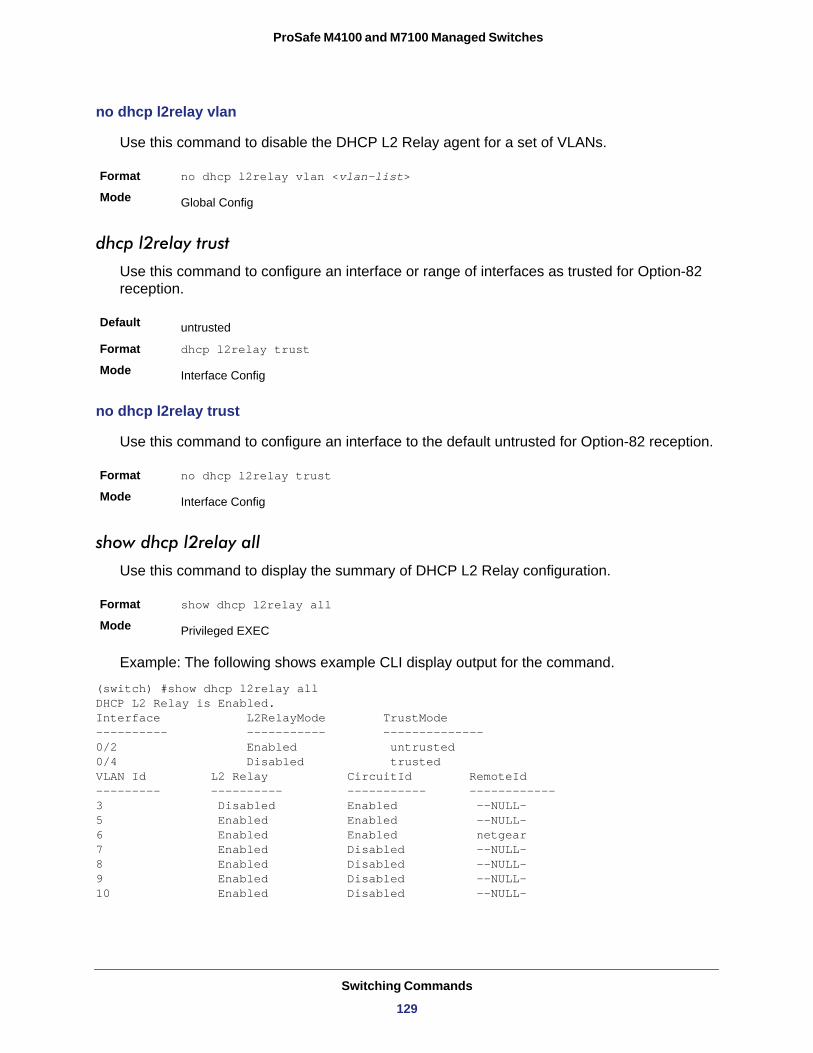
ProSafe M4100 and M7100 Managed Switches
no dhcp l2relay vlan
Use this command to disable the DHCP L2 Relay agent for a set of VLANs.
Format no dhcp l2relay vlan <vlan-list>
Mode
dhcp l2relay trust
Use this command to configure an interface or range of interfaces as trusted for Option-82 reception.
Default
Format dhcp l2relay trust
Mode
no dhcp l2relay trust
Use this command to configure an interface to the default untrusted for Option-82 reception.
Format no dhcp l2relay trust
Mode
show dhcp l2relay all
Use this command to display the summary of DHCP L2 Relay configuration.
Format show dhcp l2relay all
Mode
Example: The following shows example CLI display output for the command.
(switch) #show dhcp l2relay all DHCP L2 Relay is Enabled. Interface L2RelayMode TrustMode---------- ----------- -------------- 0/2 Enabled untrusted 0/4 Disabled trusted VLAN Id L2 Relay CircuitId RemoteId --------- ---------- ----------- ------------ 3 Disabled Enabled --NULL—5 Enabled Enabled --NULL—6 Enabled Enabled netgear 7 Enabled Disabled --NULL—8 Enabled Disabled --NULL—9 Enabled Disabled --NULL—10 Enabled Disabled --NULL—
Global Config
untrusted
Interface Config
Interface Config
Privileged EXEC
Switching Commands
129
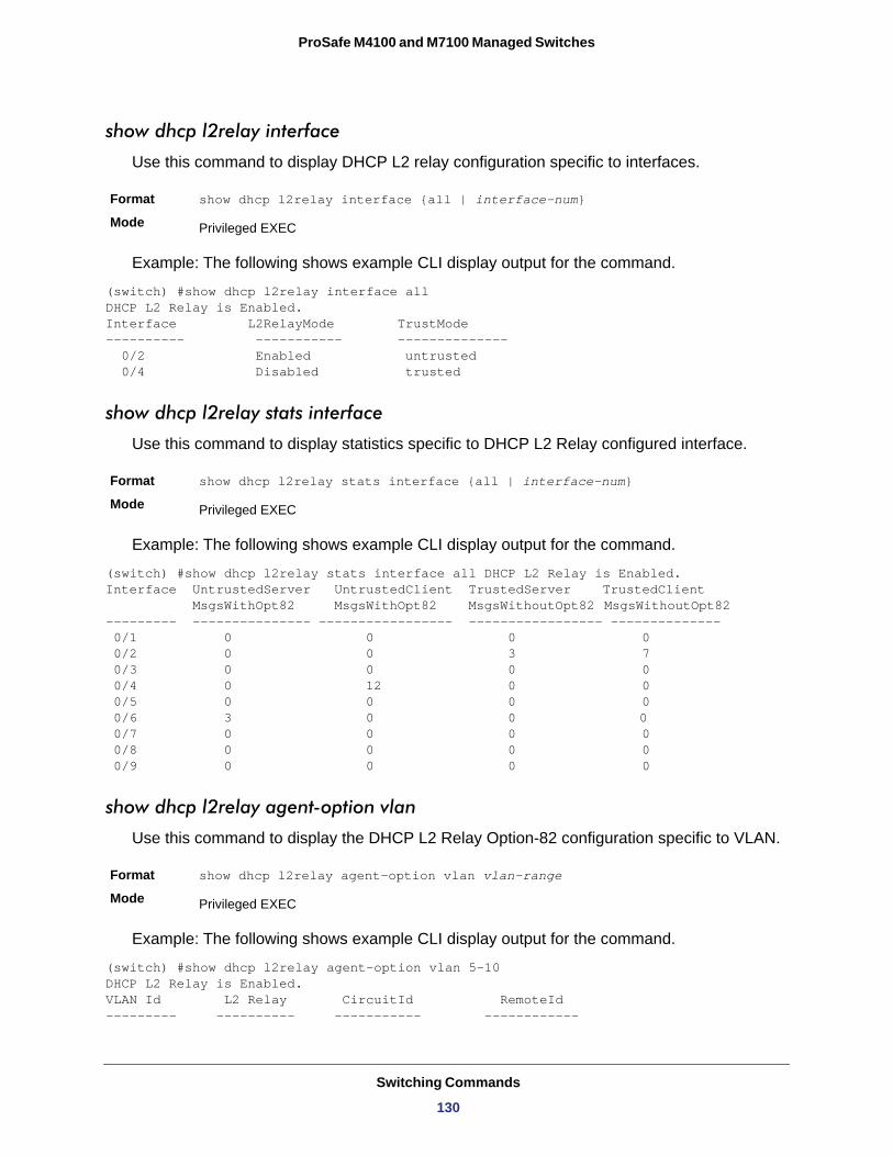
ProSafe M4100 and M7100 Managed Switches
show dhcp l2relay interface
Use this command to display DHCP L2 relay configuration specific to interfaces.
Format show dhcp l2relay interface {all | interface-num}
Mode
Example: The following shows example CLI display output for the command.
(switch) #show dhcp l2relay interface all DHCP L2 Relay is Enabled. Interface L2RelayMode TrustMode ---------- ----------- -------------- 0/2 Enabled untrusted 0/4 Disabled trusted
show dhcp l2relay stats interface
Use this command to display statistics specific to DHCP L2 Relay configured interface.
Format show dhcp l2relay stats interface {all | interface-num}
Mode
Example: The following shows example CLI display output for the command.
(switch) #show dhcp l2relay stats interface all DHCP L2 Relay is Enabled. Interface UntrustedServer UntrustedClient TrustedServer TrustedClient MsgsWithOpt82 MsgsWithOpt82 MsgsWithoutOpt82 MsgsWithoutOpt82 --------- --------------- ----------------- ----------------- -------------- 0/1 0 0 0 0 0/2 0 0 3 7 0/3 0 0 0 0 0/4 0 12 0 0 0/5 0 0 0 0 0/6 3 0 0 0 0/7 0 0 0 0 0/8 0 0 0 0 0/9 0 0 0 0
show dhcp l2relay agent-option vlan
Use this command to display the DHCP L2 Relay Option-82 configuration specific to VLAN.
Format show dhcp l2relay agent-option vlan vlan-range
Mode
Example: The following shows example CLI display output for the command.
(switch) #show dhcp l2relay agent-option vlan 5-10 DHCP L2 Relay is Enabled. VLAN Id L2 Relay CircuitId RemoteId --------- ---------- ----------- ------------
Privileged EXEC
Privileged EXEC
Privileged EXEC
Switching Commands
130
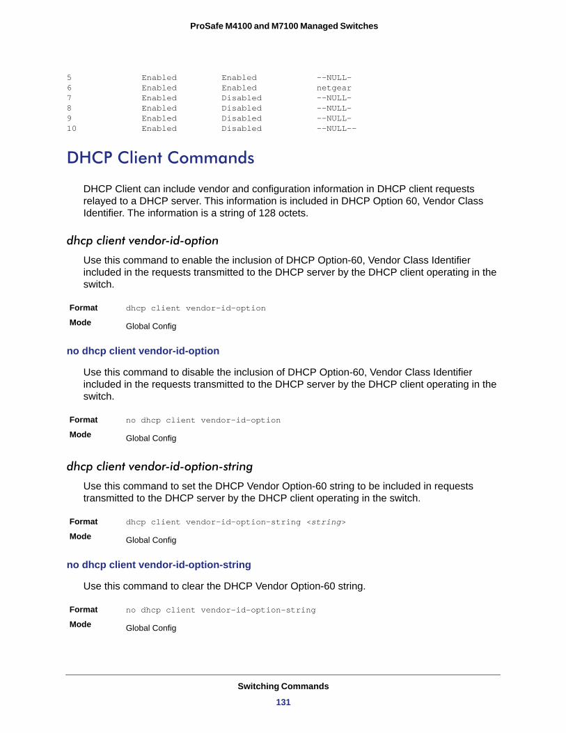
ProSafe M4100 and M7100 Managed Switches
5 Enabled Enabled --NULL—6 Enabled Enabled netgear 7 Enabled Disabled --NULL—8 Enabled Disabled --NULL—9 Enabled Disabled --NULL—10 Enabled Disabled --NULL--
DHCP Client Commands
DHCP Client can include vendor and configuration information in DHCP client requests relayed to a DHCP server. This information is included in DHCP Option 60, Vendor Class Identifier. The information is a string of 128 octets.
dhcp client vendor-id-option
Use this command to enable the inclusion of DHCP Option-60, Vendor Class Identifier included in the requests transmitted to the DHCP server by the DHCP client operating in the switch.
Format dhcp client vendor-id-option
Mode
no dhcp client vendor-id-option
Use this command to disable the inclusion of DHCP Option-60, Vendor Class Identifier included in the requests transmitted to the DHCP server by the DHCP client operating in the switch.
Format no dhcp client vendor-id-option
Mode
dhcp client vendor-id-option-string
Use this command to set the DHCP Vendor Option-60 string to be included in requests transmitted to the DHCP server by the DHCP client operating in the switch.
Format dhcp client vendor-id-option-string <string>
Mode
no dhcp client vendor-id-option-string
Use this command to clear the DHCP Vendor Option-60 string.
Format no dhcp client vendor-id-option-string
Mode
Global Config
Global Config
Global Config
Global Config
Switching Commands
131
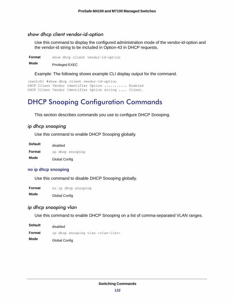
ProSafe M4100 and M7100 Managed Switches
show dhcp client vendor-id-option
Use this command to display the configured administration mode of the vendor-id-option and the vendor-id string to be included in Option-43 in DHCP requests.
Format show dhcp client vendor-id-option
Mode
Example: The following shows example CLI display output for the command.
(switch) #show dhcp client vendor-id-option DHCP Client Vendor Identifier Option ........... Enabled DHCP Client Vendor Identifier Option string .... Client.
DHCP Snooping Configuration Commands
This section describes commands you use to configure DHCP Snooping.
ip dhcp snooping
Use this command to enable DHCP Snooping globally.
Default
Format ip dhcp snooping
Mode
no ip dhcp snooping
Use this command to disable DHCP Snooping globally.
Format no ip dhcp snooping
Mode
ip dhcp snooping vlan
Use this command to enable DHCP Snooping on a list of comma-separated VLAN ranges.
Default
Format ip dhcp snooping vlan <vlan-list>
Mode
Privileged EXEC
disabled
Global Config
Global Config
disabled
Global Config
Switching Commands
132
ProSafe M4100 and M7100 Managed Switches
no ip dhcp snooping vlan
Use this command to disable DHCP Snooping on VLANs.
Format no ip dhcp snooping vlan <vlan-list>
Mode
ip dhcp snooping verify mac-address
Use this command to enable verification of the source MAC address with the client hardware address in the received DCHP message.
Default
Format ip dhcp snooping verify mac-address
Mode
no ip dhcp snooping verify mac-address
Use this command to disable verification of the source MAC address with the client hardware address.
Format no ip dhcp snooping verify mac-address
Mode
ip dhcp snooping database
Use this command to configure the persistent location of the DHCP Snooping database. This can be local or a remote file on a given IP machine.
Default
Format ip dhcp snooping database {local|tftp://hostIP/filename}
Mode
ip dhcp snooping database write-delay
Use this command to configure the interval in seconds at which the DHCP Snooping database will be persisted. The interval value ranges from 15 to 86,400 seconds.
Default
Format ip dhcp snooping database write-delay <in seconds>
Mode
Global Config
enabled
Global Config
Global Config
local
Global Config
300 seconds
Global Config
Switching Commands
133
ProSafe M4100 and M7100 Managed Switches
no ip dhcp snooping database write-delay
Use this command to set the write delay value to the default value.
Format no ip dhcp snooping database write-delay
Mode
ip dhcp snooping binding
Use this command to configure static DHCP Snooping binding.
Format ip dhcp snooping binding <mac-address> vlan <vlan id> <ip address> interface <interface id>
Mode
no ip dhcp snooping binding <mac-address>
Use this command to remove the DHCP static entry from the DHCP Snooping database.
Format no ip dhcp snooping binding <mac-address>
Mode
ip verify binding
Use this command to configure static IP source guard (IPSG) entries.
Format ip verify binding <mac-address> vlan <vlan id> <ip address> interface <interface id>
Mode
no ip verify binding
Use this command to remove the IPSG static entry from the IPSG database.
Format no ip verify binding <mac-address> vlan <vlan id> <ip address> interface <interface id>
Mode
ip dhcp snooping limit
Use this command to control the rate at which the DHCP Snooping messages come. The default rate is 15 pps with a range from 0 to 30 pps. The default burst level is 1 second with a range of 1–15 seconds.
Global Config
Global Config
Global Config
Global Config
Global Config
Default 15 pps for rate limiting and 1 sec for burst interval
Switching Commands
134
ProSafe M4100 and M7100 Managed Switches
no ip dhcp snooping limit
Use this command to set the rate at which the DHCP Snooping messages come, and the burst level, to the defaults.
Format no ip dhcp snooping limit
Mode
ip dhcp snooping log-invalid
Use this command to control the logging DHCP messages filtration by the DHCP Snooping application.
Default
Format ip dhcp snooping log-invalid
Mode
no ip dhcp snooping log-invalid
Use this command to disable the logging DHCP messages filtration by the DHCP Snooping application.
Format no ip dhcp snooping log-invalid
Mode
ip dhcp snooping trust
Use this command to configure the port as trusted.
Default
Format ip dhcp snooping trust
Mode
no ip dhcp snooping trust
Use this command to configure the port as untrusted.
Format no ip dhcp snooping trust
Mode
Format ip dhcp snooping limit {rate pps [burst interval seconds]}
Mode Interface Config
Interface Config
disabled
Interface Config
Interface Config
disabled
Interface Config
Interface Config
Switching Commands
135
ProSafe M4100 and M7100 Managed Switches
ip verify source
Use this command to configure the IPSG source ID attribute to filter the data traffic in the hardware. Source ID is the combination of IP address and MAC address. Normal command allows data traffic filtration based on the IP address. With the “port-security” option, the data traffic will be filtered based on the IP and MAC addresses.
Default the source ID is the IP address
Format ip verify source {port-security}
Mode
no ip verify source
Use this command to disable the IPSG configuration in the hardware. You cannot disable port-security alone if it is configured.
Format no ip verify source
Mode
show ip dhcp snooping
Use this command to display the DHCP Snooping global configurations and per port configurations.
Format show ip dhcp snooping
Mode • Privileged EXEC• User EXEC
Example: The following shows example CLI display output for the command.
(switch) #show ip dhcp snooping
DHCP snooping is DisabledDHCP snooping source MAC verification is enabledDHCP snooping is enabled on the following VLANs:11 - 30, 40
Interface Trusted Log Invalid Pkts --------- -------- ----------------
Interface Config
Interface Config
Term Definition
Interface The interface for which data is displayed.
Trusted If it is enabled, DHCP snooping considers the port as trusted. The factory default is disabled.
Log Invalid Pkts If it is enabled, DHCP snooping application logs invalid packets on the specified interface.
Switching Commands
136
ProSafe M4100 and M7100 Managed Switches
0/1 Yes No 0/2 No Yes 0/3 No Yes 0/4 No No0/6 No No
show ip dhcp snooping binding
Use this command to display the DHCP Snooping binding entries. To restrict the output, use the following options:
• Dynamic: Restrict the output based on DCHP snooping.• Interface: Restrict the output based on a specific interface.• Static: Restrict the output based on static entries.• VLAN: Restrict the output based on VLAN.
Format show ip dhcp snooping binding [{static/dynamic}] [interface slot/port] [vlan id]
Mode • Privileged EXEC• User EXEC
Example: The following shows example CLI display output for the command.
(switch) #show ip dhcp snooping binding
Total number of bindings: 2
MAC Address IP Address VLAN Interface Type Lease (Secs)------------------ ------------ ---- --------- ---- -------------00:02:B3:06:60:80 210.1.1.3 10 0/1 8640000:0F:FE:00:13:04 210.1.1.4 10 0/1 86400
Term Definition
MAC Address Displays the MAC address for the binding that was added. The MAC address is the key to the binding database.
IP Address Displays the valid IP address for the binding rule.
VLAN The VLAN for the binding rule.
Interface The interface to add a binding into the DHCP snooping interface.
Type Binding type; statically configured from the CLI or dynamically learned.
Lease (sec) The remaining lease time for the entry.
Switching Commands
137
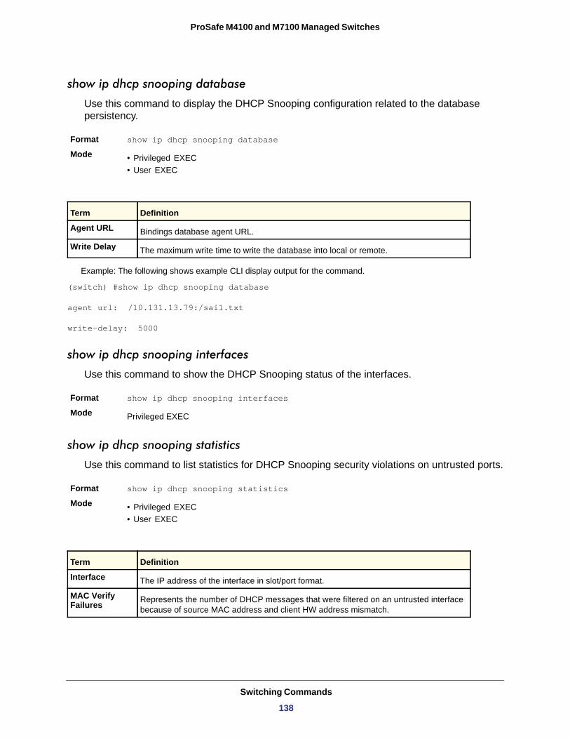
ProSafe M4100 and M7100 Managed Switches
show ip dhcp snooping database
Use this command to display the DHCP Snooping configuration related to the database persistency.
Format show ip dhcp snooping database
Mode • Privileged EXEC• User EXEC
Example: The following shows example CLI display output for the command.
(switch) #show ip dhcp snooping database
agent url: /10.131.13.79:/sai1.txt
write-delay: 5000
show ip dhcp snooping interfaces
Use this command to show the DHCP Snooping status of the interfaces.
Format show ip dhcp snooping interfaces
Mode
show ip dhcp snooping statistics
Use this command to list statistics for DHCP Snooping security violations on untrusted ports.
Format show ip dhcp snooping statistics
Mode • Privileged EXEC• User EXEC
Term Definition
Agent URL Bindings database agent URL.
Write Delay The maximum write time to write the database into local or remote.
Privileged EXEC
Term Definition
Interface The IP address of the interface in slot/port format.
MAC Verify Failures Represents the number of DHCP messages that were filtered on an untrusted interface
because of source MAC address and client HW address mismatch.
Switching Commands
138
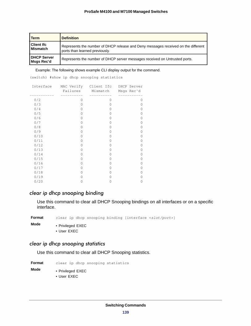
ProSafe M4100 and M7100 Managed Switches
Example: The following shows example CLI display output for the command.
(switch) #show ip dhcp snooping statistics
Interface MAC Verify Client Ifc DHCP Server Failures Mismatch Msgs Rec'd----------- ---------- ---------- ----------- 0/2 0 0 0 0/3 0 0 0 0/4 0 0 0 0/5 0 0 0 0/6 0 0 0 0/7 0 0 0 0/8 0 0 0 0/9 0 0 0 0/10 0 0 0 0/11 0 0 0 0/12 0 0 0 0/13 0 0 0 0/14 0 0 0 0/15 0 0 0 0/16 0 0 0 0/17 0 0 0 0/18 0 0 0 0/19 0 0 0 0/20 0 0 0
clear ip dhcp snooping binding
Use this command to clear all DHCP Snooping bindings on all interfaces or on a specific interface.
Format clear ip dhcp snooping binding [interface <slot/port>]
Mode • Privileged EXEC• User EXEC
clear ip dhcp snooping statistics
Use this command to clear all DHCP Snooping statistics.
Format clear ip dhcp snooping statistics
Mode • Privileged EXEC• User EXEC
Client Ifc Mismatch Represents the number of DHCP release and Deny messages received on the different
ports than learned previously.
DHCP Server Msgs Rec’d Represents the number of DHCP server messages received on Untrusted ports.
Term Definition
Switching Commands
139
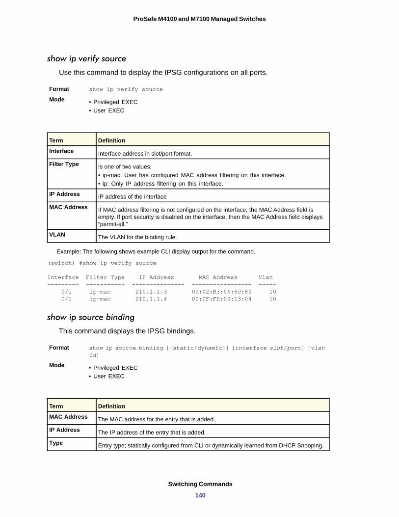
ProSafe M4100 and M7100 Managed Switches
show ip verify source
Use this command to display the IPSG configurations on all ports.
Format show ip verify source
Mode • Privileged EXEC• User EXEC
Example: The following shows example CLI display output for the command.
(switch) #show ip verify source
Interface Filter Type IP Address MAC Address Vlan--------- ----------- --------------- ----------------- ----- 0/1 ip-mac 210.1.1.3 00:02:B3:06:60:80 10 0/1 ip-mac 210.1.1.4 00:0F:FE:00:13:04 10
show ip source binding
This command displays the IPSG bindings.
Format show ip source binding [{static/dynamic}] [interface slot/port] [vlan id]
Mode • Privileged EXEC• User EXEC
Term Definition
Interface Interface address in slot/port format.
Filter Type Is one of two values:• ip-mac: User has configured MAC address filtering on this interface.• ip: Only IP address filtering on this interface.
IP Address IP address of the interface
MAC Address If MAC address filtering is not configured on the interface, the MAC Address field is empty. If port security is disabled on the interface, then the MAC Address field displays “permit-all.”
VLAN The VLAN for the binding rule.
Term Definition
MAC Address The MAC address for the entry that is added.
IP Address The IP address of the entry that is added.
Type Entry type; statically configured from CLI or dynamically learned from DHCP Snooping.
Switching Commands
140
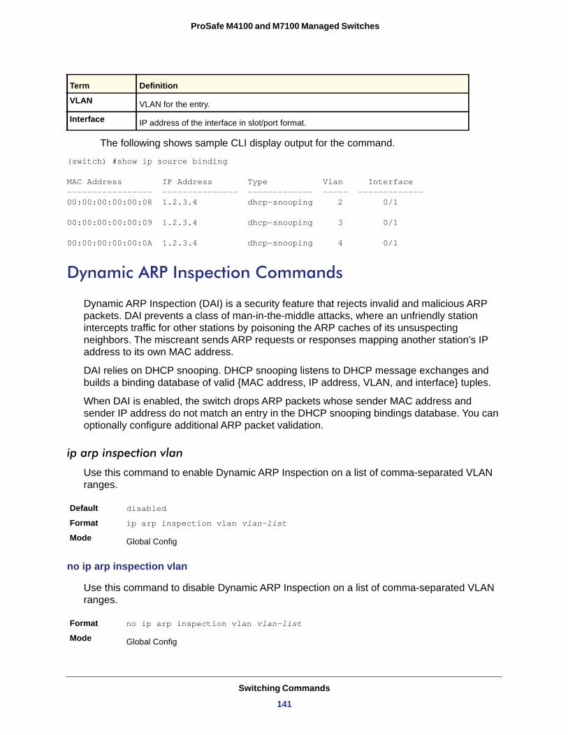
ProSafe M4100 and M7100 Managed Switches
The following shows sample CLI display output for the command.
(switch) #show ip source binding
MAC Address IP Address Type Vlan Interface----------------- --------------- ------------- ----- -------------00:00:00:00:00:08 1.2.3.4 dhcp-snooping 2 0/1
00:00:00:00:00:09 1.2.3.4 dhcp-snooping 3 0/1
00:00:00:00:00:0A 1.2.3.4 dhcp-snooping 4 0/1
Dynamic ARP Inspection Commands
Dynamic ARP Inspection (DAI) is a security feature that rejects invalid and malicious ARP packets. DAI prevents a class of man-in-the-middle attacks, where an unfriendly station intercepts traffic for other stations by poisoning the ARP caches of its unsuspecting neighbors. The miscreant sends ARP requests or responses mapping another station’s IP address to its own MAC address.
DAI relies on DHCP snooping. DHCP snooping listens to DHCP message exchanges and builds a binding database of valid {MAC address, IP address, VLAN, and interface} tuples.
When DAI is enabled, the switch drops ARP packets whose sender MAC address and sender IP address do not match an entry in the DHCP snooping bindings database. You can optionally configure additional ARP packet validation.
ip arp inspection vlan
Use this command to enable Dynamic ARP Inspection on a list of comma-separated VLAN ranges.
Default disabled
Format ip arp inspection vlan vlan-list
Mode
no ip arp inspection vlan
Use this command to disable Dynamic ARP Inspection on a list of comma-separated VLAN ranges.
Format no ip arp inspection vlan vlan-list
Mode
VLAN VLAN for the entry.
Interface IP address of the interface in slot/port format.
Global Config
Global Config
Term Definition
Switching Commands
141
ProSafe M4100 and M7100 Managed Switches
ip arp inspection validate
Use this command to enable additional validation checks like source-mac validation, destination-mac validation, and ip address validation on the received ARP packets. Each command overrides the configuration of the previous command. For example, if a command enables src-mac and dst-mac validations, and a second command enables IP validation only, the src-mac and dst-mac validations are disabled as a result of the second command.
Default disabled
Format ip arp inspection validate {[src-mac] [dst-mac] [ip]}
Mode
no ip arp inspection validate
Use this command to disable the additional validation checks on the received ARP packets.
Format no ip arp inspection validate {[src-mac] [dst-mac] [ip]}
Mode
ip arp inspection vlan logging
Use this command to enable logging of invalid ARP packets on a list of comma-separated VLAN ranges.
Default enabled
Format ip arp inspection vlan vlan-list logging
Mode
no ip arp inspection vlan logging
Use this command to disable logging of invalid ARP packets on a list of comma-separated VLAN ranges.
Format no ip arp inspection vlan vlan-list logging
Mode
ip arp inspection trust
Use this command to configure an interface as trusted for Dynamic ARP Inspection.
Default enabled
Format ip arp inspection trust
Mode
Global Config
Global Config
Global Config
Global Config
Interface Config
Switching Commands
142
ProSafe M4100 and M7100 Managed Switches
no ip arp inspection trust
Use this command to configure an interface as untrusted for Dynamic ARP Inspection.
Format no ip arp inspection trust
Mode
ip arp inspection limit
Use this command to configure the rate limit and burst interval values for an interface. Configuring none for the limit means that the interface is not rate limited for Dynamic ARP Inspections.
Note: The user interface will accept a rate limit for a trusted interface, but the limit will not be enforced unless the interface is configured to be untrusted.
no ip arp inspection limit
Use this command to set the rate limit and burst interval values for an interface to the default values of 15 pps and 1 second, respectively.
Format no ip arp inspection limit
Mode
ip arp inspection filter
Use this command to configure the ARP ACL used to filter invalid ARP packets on a list of comma-separated VLAN ranges. If the static keyword is given, packets that do not match a permit statement are dropped without consulting the DHCP snooping bindings.
Default No ARP ACL is configured on a VLAN
Format ip arp inspection filter acl-name vlan vlan-list [static]
Mode
Interface Config
Default 15 pps for rate and 1 second for burst-interval
Format ip arp inspection limit {rate pps [burst interval seconds] | none}
Mode Interface Config
Interface Config
Global Config
Switching Commands
143
ProSafe M4100 and M7100 Managed Switches
no ip arp inspection filter
Use this command to unconfigure the ARP ACL used to filter invalid ARP packets on a list of comma-separated VLAN ranges.
Format no ip arp inspection filter acl-name vlan vlan-list [static]
Mode
arp access-list
Use this command to create an ARP ACL.
Format arp access-list acl-name
Mode
no arp access-list
Use this command to delete a configured ARP ACL.
Format no arp access-list acl-name
Mode
permit ip host mac host
Use this command to configure a rule for a valid IP address and MAC address combination used in ARP packet validation.
Format permit ip host sender-ip mac host sender-mac
Mode
no permit ip host mac host
Use this command to delete a rule for a valid IP and MAC combination.
Format no permit ip host sender-ip mac host sender-mac
Mode
show ip arp inspection
Use this command to display the Dynamic ARP Inspection global configuration and configuration on all the VLANs. With the vlan-list argument (that is, comma-separated VLAN ranges), the command displays the global configuration and configuration on all the VLANs in
Global Config
Global Config
Global Config
ARP Access-list Config
ARP Access-list Config
Switching Commands
144
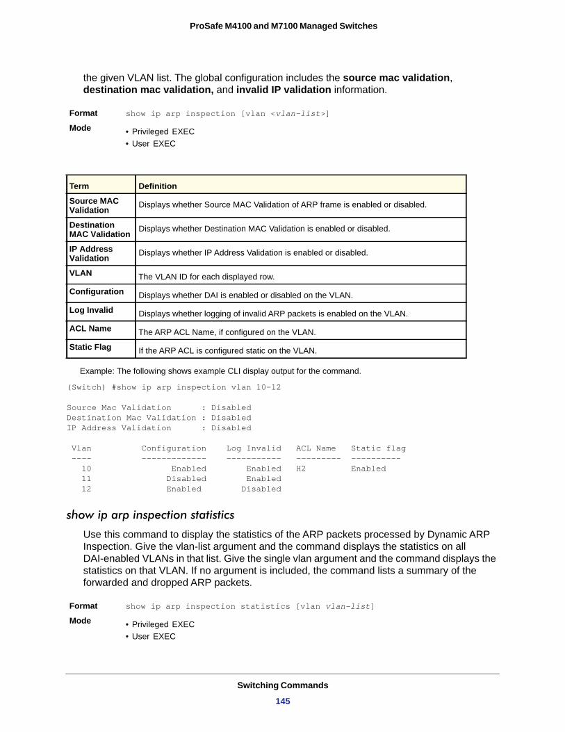
ProSafe M4100 and M7100 Managed Switches
the given VLAN list. The global configuration includes the source mac validation, destination mac validation, and invalid IP validation information.
Format show ip arp inspection [vlan <vlan-list>]
Mode • Privileged EXEC• User EXEC
Example: The following shows example CLI display output for the command.
(Switch) #show ip arp inspection vlan 10-12
Source Mac Validation : DisabledDestination Mac Validation : DisabledIP Address Validation : Disabled
Vlan Configuration Log Invalid ACL Name Static flag ---- ------------- ----------- --------- ---------- 10 Enabled Enabled H2 Enabled 11 Disabled Enabled 12 Enabled Disabled
show ip arp inspection statistics
Use this command to display the statistics of the ARP packets processed by Dynamic ARP Inspection. Give the vlan-list argument and the command displays the statistics on all DAI-enabled VLANs in that list. Give the single vlan argument and the command displays the statistics on that VLAN. If no argument is included, the command lists a summary of the forwarded and dropped ARP packets.
Format show ip arp inspection statistics [vlan vlan-list]
Mode • Privileged EXEC• User EXEC
Term Definition
Source MAC Validation Displays whether Source MAC Validation of ARP frame is enabled or disabled.
Destination MAC Validation Displays whether Destination MAC Validation is enabled or disabled.
IP Address Validation Displays whether IP Address Validation is enabled or disabled.
VLAN The VLAN ID for each displayed row.
Configuration Displays whether DAI is enabled or disabled on the VLAN.
Log Invalid Displays whether logging of invalid ARP packets is enabled on the VLAN.
ACL Name The ARP ACL Name, if configured on the VLAN.
Static Flag If the ARP ACL is configured static on the VLAN.
Switching Commands
145
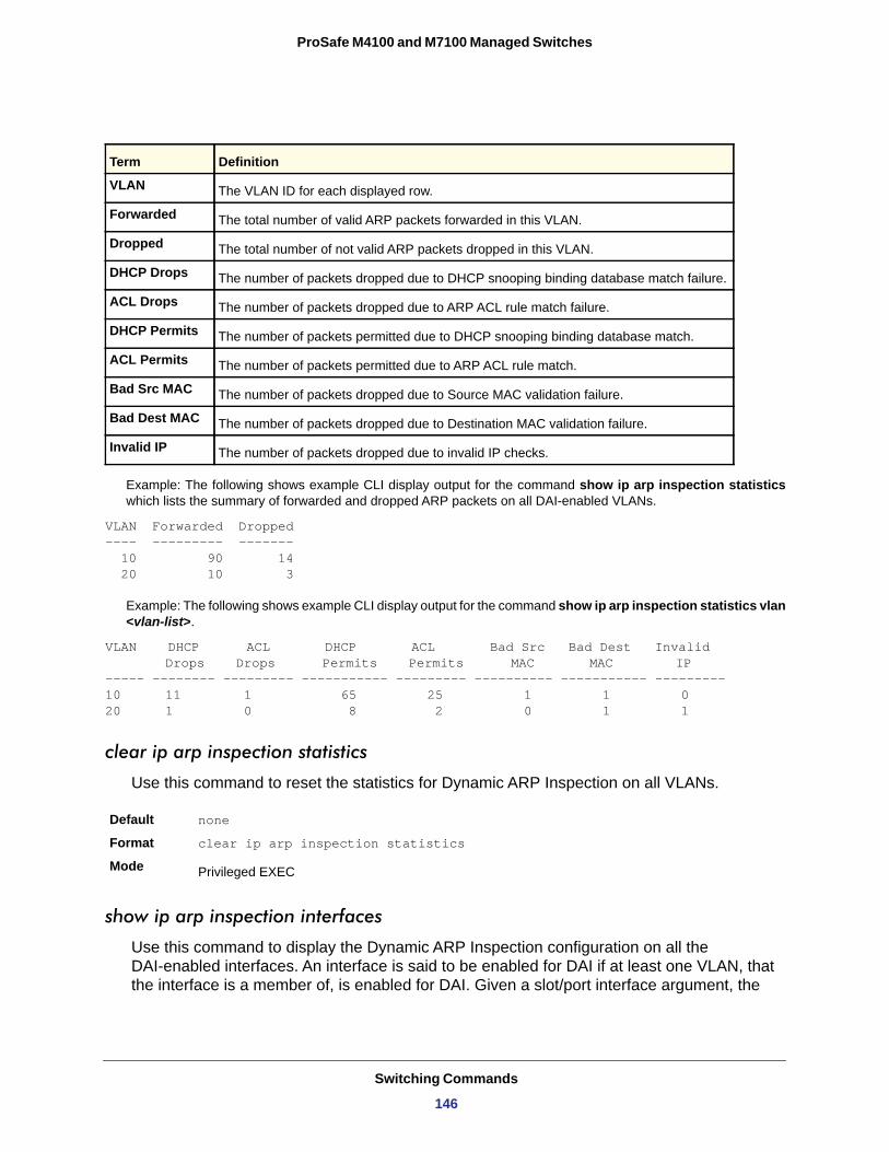
ProSafe M4100 and M7100 Managed Switches
Example: The following shows example CLI display output for the command show ip arp inspection statisticswhich lists the summary of forwarded and dropped ARP packets on all DAI-enabled VLANs.
VLAN Forwarded Dropped---- --------- ------- 10 90 14 20 10 3
Example: The following shows example CLI display output for the command show ip arp inspection statistics vlan <vlan-list>.
VLAN DHCP ACL DHCP ACL Bad Src Bad Dest Invalid Drops Drops Permits Permits MAC MAC IP
----- -------- --------- ----------- --------- ---------- ----------- ---------10 11 1 65 25 1 1 020 1 0 8 2 0 1 1
clear ip arp inspection statistics
Use this command to reset the statistics for Dynamic ARP Inspection on all VLANs.
Default none
Format clear ip arp inspection statistics
Mode
show ip arp inspection interfaces
Use this command to display the Dynamic ARP Inspection configuration on all the DAI-enabled interfaces. An interface is said to be enabled for DAI if at least one VLAN, that the interface is a member of, is enabled for DAI. Given a slot/port interface argument, the
Term Definition
VLAN The VLAN ID for each displayed row.
Forwarded The total number of valid ARP packets forwarded in this VLAN.
Dropped The total number of not valid ARP packets dropped in this VLAN.
DHCP Drops The number of packets dropped due to DHCP snooping binding database match failure.
ACL Drops The number of packets dropped due to ARP ACL rule match failure.
DHCP Permits The number of packets permitted due to DHCP snooping binding database match.
ACL Permits The number of packets permitted due to ARP ACL rule match.
Bad Src MAC The number of packets dropped due to Source MAC validation failure.
Bad Dest MAC The number of packets dropped due to Destination MAC validation failure.
Invalid IP The number of packets dropped due to invalid IP checks.
Privileged EXEC
Switching Commands
146
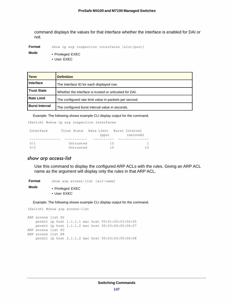
ProSafe M4100 and M7100 Managed Switches
command displays the values for that interface whether the interface is enabled for DAI or not.
Format show ip arp inspection interfaces [slot/port]
Mode • Privileged EXEC• User EXEC
Example: The following shows example CLI display output for the command.
(Switch) #show ip arp inspection interfaces
Interface Trust State Rate Limit Burst Interval (pps) (seconds) --------------- ----------- ---------- --------------- 0/1 Untrusted 15 1 0/2 Untrusted 10 10
show arp access-list
Use this command to display the configured ARP ACLs with the rules. Giving an ARP ACL name as the argument will display only the rules in that ARP ACL.
Format show arp access-list [acl-name]
Mode • Privileged EXEC• User EXEC
Example: The following shows example CLI display output for the command.
(Switch) #show arp access-list
ARP access list H2 permit ip host 1.1.1.1 mac host 00:01:02:03:04:05 permit ip host 1.1.1.2 mac host 00:03:04:05:06:07ARP access list H3ARP access list H4 permit ip host 2.1.1.2 mac host 00:03:04:05:06:08
Term Definition
Interface The interface ID for each displayed row.
Trust State Whether the interface is trusted or untrusted for DAI.
Rate Limit The configured rate limit value in packets per second.
Burst Interval The configured burst interval value in seconds.
Switching Commands
147
ProSafe M4100 and M7100 Managed Switches
IGMP Snooping Configuration Commands
This section describes the commands you use to configure IGMP snooping. The software supports IGMP Versions 1, 2, and 3. The IGMP snooping feature can help conserve bandwidth because it allows the switch to forward IP multicast traffic only to connected hosts that request multicast traffic. IGMPv3 adds source filtering capabilities to IGMP versions 1 and 2.
set igmp
This command enables IGMP Snooping on the system (Global Config Mode) or an interface (Interface Config Mode). This command also enables IGMP snooping on a particular VLAN (VLAN Config Mode) and can enable IGMP snooping on all interfaces participating in a VLAN.
If an interface has IGMP Snooping enabled and you enable this interface for routing or enlist it as a member of a port-channel (LAG), IGMP Snooping functionality is disabled on that interface. IGMP Snooping functionality is re-enabled if you disable routing or remove port-channel (LAG) membership from an interface that has IGMP Snooping enabled.
The IGMP application supports the following activities:
• Validation of the IP header checksum (as well as the IGMP header checksum) and discarding of the frame upon checksum error.
• Maintenance of the forwarding table entries based on the MAC address versus the IP address.
• Flooding of unregistered multicast data packets to all ports in the VLAN.
Default
Format set igmp
Mode • Global Config• Interface Config
Format set igmp <vlanid>Mode
no set igmp
This command disables IGMP Snooping on the system, an interface, or a VLAN.
Format no set igmp
Mode • Global Config• Interface Config
disabled
VLAN Config
Switching Commands
148
ProSafe M4100 and M7100 Managed Switches
Format no set igmp <vlanid>
Mode
set igmp interfacemode
This command enables IGMP Snooping on all interfaces. If an interface has IGMP Snooping enabled and you enable this interface for routing or enlist it as a member of a port-channel (LAG), IGMP Snooping functionality is disabled on that interface. IGMP Snooping functionality is re-enabled if you disable routing or remove port-channel (LAG) membership from an interface that has IGMP Snooping enabled.
Default
Format set igmp interfacemode
Mode
no set igmp interfacemode
This command disables IGMP Snooping on all interfaces.
Format no set igmp interfacemode
Mode
set igmp fast-leave
This command enables or disables IGMP Snooping fast-leave admin mode on a selected interface or VLAN. Enabling fast-leave allows the switch to immediately remove the layer 2 LAN interface from its forwarding table entry upon receiving an IGMP leave message for that multicast group without first sending out MAC-based general queries to the interface.
You should enable fast-leave admin mode only on VLANs where only one host is connected to each layer 2 LAN port. This prevents the inadvertent dropping of the other hosts that were connected to the same layer 2 LAN port but were still interested in receiving multicast traffic directed to that group. Also, fast-leave processing is supported only with IGMP version 2 hosts.
Default
Format set igmp fast-leave
Mode
Format set igmp fast-leave <vlan_id>Mode
VLAN Config
disabled
Global Config
Global Config
disabled
Interface Config
VLAN Config
Switching Commands
149
ProSafe M4100 and M7100 Managed Switches
no set igmp fast-leave
This command disables IGMP Snooping fast-leave admin mode on a selected interface.
Format no set igmp fast-leave
Mode
Format no set igmp fast-leave <vlan_id>Mode
set igmp groupmembership-interval
This command sets the IGMP Group Membership Interval time on a VLAN, one interface, or all interfaces. The Group Membership Interval time is the amount of time in seconds that a switch waits for a report from a particular group on a particular interface before deleting the interface from the entry. This value must be greater than the IGMPv3 Maximum Response time value. The range is 2–3600 seconds.
Default
Format set igmp groupmembership-interval <2-3600>
Mode • Interface Config• Global Config
Format set igmp groupmembership-interval <vlan_id> <2-3600>
Mode
no set igmp groupmembership-interval
This command sets the IGMPv3 Group Membership Interval time to the default value.
Format no set igmp groupmembership-interval
Mode • Interface Config• Global Config
Format no set igmp groupmembership-interval <vlan_id>
Mode
set igmp maxresponse
This command sets the IGMP Maximum Response time for the system, or on a particular interface or VLAN. The Maximum Response time is the amount of time in seconds that a switch will wait after sending a query on an interface because it did not receive a report for a
Interface Config
VLAN Config
260 seconds
VLAN Config
VLAN Config
Switching Commands
150
ProSafe M4100 and M7100 Managed Switches
particular group in that interface. This value must be less than the IGMP Query Interval time value. The range is 1–25 seconds.
Default
Format set igmp maxresponse <1-25>
Mode • Global Config• Interface Config
Format set igmp maxresponse <vlan_id> <1-25>
Mode
no set igmp maxresponse
This command sets the max response time (on the interface or VLAN) to the default value.
Format no set igmp maxresponse
Mode • Global Config• Interface Config
Format no set igmp maxresponse <vlan_id>
Mode
set igmp mcrtrexpiretime
This command sets the Multicast Router Present Expiration time. The time is set for the system, on a particular interface or VLAN. This is the amount of time in seconds that a switch waits for a query to be received on an interface before the interface is removed from the list of interfaces with multicast routers attached. The range is 0–3600 seconds. A value of 0 indicates an infinite time-out, that is, no expiration.
Default
Format set igmp mcrtrexpiretime <0-3600>
Mode • Global Config• Interface Config
Format set igmp mcrtrexpiretime <vlan_id> <0-3600>
Mode
10 seconds
VLAN Config
VLAN Config
0
VLAN Config
Switching Commands
151
ProSafe M4100 and M7100 Managed Switches
no set igmp mcrtrexpiretime
This command sets the Multicast Router Present Expiration time to 0. The time is set for the system, on a particular interface or a VLAN.
Format no set igmp mcrtrexpiretime
Mode • Global Config• Interface Config
Format no set igmp mcrtrexpiretime <vlan_id>
Mode
set igmp mrouter
This command configures the VLAN ID (<vlanId>) that has the multicast router mode enabled.
Format set igmp mrouter <vlan_id>
Mode
no set igmp mrouter
This command disables multicast router mode for a particular VLAN ID (<vlan_id>).
Format no set igmp mrouter <vlan_id>
Mode
set igmp mrouter interface
This command configures the interface as a multicast router interface. When configured as a multicast router interface, the interface is treated as a multicast router interface in all VLANs.
Default
Format set igmp mrouter interface
Mode
no set igmp mrouter interface
This command disables the status of the interface as a statically configured multicast router interface.
Format no set igmp mrouter interface
Mode
VLAN Config
Interface Config
Interface Config
disabled
Interface Config
Interface Config
Switching Commands
152
ProSafe M4100 and M7100 Managed Switches
set igmp report-suppression
Use this command to suppress the IGMP reports on a given VLAN ID. In order to optimize the number of reports traversing the network with no added benefits, a Report Suppression mechanism is implemented. When more than one client responds to an MGMD query for the same Multicast Group address within the max-response-time, only the first response is forwarded to the query and others are suppressed at the switch.
Default
Format set igmp report-suppression <1-4093>Mode
no set igmp report-suppression
Use this command to restore the system default.
Format no set igmp report-suppression
Mode
set igmp header-validation
If IGMP IP header validation is enabled, then 3 fields TTL (Time To Live), ToS (Type of Service), and Router Alert options are checked. The fields checked depend on the IGMP version. The TTL field is validated in all the versions (IGMPv1, IGMPv2 and IGMPv3). The Router Alert field is validated in IGMPv2 and IGMPv3. The ToS field is validated only in IGMP version3.
Default
Format set igmp header-validation
Mode
no set igmp header-validation
This command disabled the IGMP IP header validation..
Format no set igmp header-validation
Mode
Disabled
VLAN Config
VLAN Config
Enabled
Global Config
Global Config
Switching Commands
153
ProSafe M4100 and M7100 Managed Switches
mac address-table multicast forbidden-unregistered vlan
Use this command to forbid forwarding unregistered multicast addresses (in other words, unknown multicast traffic) on a given VLAN ID.
Default
Format mac address-table multicast forbidden-unregistered vlan <1-4093>
Mode
no mac address-table multicast forbidden-unregistered vlan
Use this command to restore the default.
Format no mac address-table multicast forbidden-unregistered vlan
Mode
mac address-table multicast forward-unregistered vlan
Use this command to enable forwarding unregistered multicast address (in other words, unknown multicast traffic) on a given VLAN ID.
Format mac address-table multicast forward-unregistered vlan <1-4093>
Mode
mac address-table multicast forward-all vlan
Use this command to enable forwarding of all multicast packets on a given VLAN ID.
Format mac address-table multicast forward-all vlan <1-4093>Mode
no mac address-table multicast forward-all vlan
Use this command to restore the system default.
Format no mac address-table multicast forward-all vlan
Mode
Disabled
Global Config
Global Config
Global Config
Global Config
Global Config
Switching Commands
154
ProSafe M4100 and M7100 Managed Switches
show igmpsnooping
This command displays IGMP Snooping information. Configured information is displayed whether or not IGMP Snooping is enabled.
Format show igmpsnooping [<slot/port> | <vlan_id>]
Mode
When the optional arguments <slot/port> or <vlan_id> are not used, the command displays the following information:
Admin Mode
Multicast Control Frame Count
Interface Enabled for IGMP Snooping
VLANS Enabled for IGMP Snooping
When you specify the <slot/port> values, the following information appears:
IGMP Snooping Admin Mode
Fast Leave Mode
Group Membership Interval
Maximum Response Time
Multicast Router Expiry Time
When you specify a value for <vlan_id>, the following information appears:
Privileged EXEC
Term Definition
Indicates whether or not IGMP Snooping is active on the switch.
The number of multicast control frames that are processed by the CPU.
The list of interfaces on which IGMP Snooping is enabled.
The list of VLANS on which IGMP Snooping is enabled.
Term Definition
Indicates whether IGMP Snooping is active on the interface.
Indicates whether IGMP Snooping Fast-leave is active on the interface.
The amount of time in seconds that a switch will wait for a report from a particular group on a particular interface before deleting the interface from the entry. This value may be configured.
The amount of time the switch waits after it sends a query on an interface because it did not receive a report for a particular group on that interface. This value may be configured.
The amount of time to wait before removing an interface from the list of interfaces with multicast routers attached. The interface is removed if a query is not received. This value may be configured.
Term Definition
VLAN ID The VLAN ID.
IGMP Snooping Admin Mode Indicates whether IGMP Snooping is active on the VLAN.
Switching Commands
155
ProSafe M4100 and M7100 Managed Switches
show igmpsnooping mrouter interface
This command displays information about statically configured ports.
Format show igmpsnooping mrouter interface <slot/port>
Mode
Interface
Multicast Router Attached
VLAN ID
show igmpsnooping mrouter vlan
This command displays information about statically configured ports.
Format show igmpsnooping mrouter vlan <slot/port>
Mode
Interface
VLAN ID
Fast Leave Mode Indicates whether IGMP Snooping Fast-leave is active on the VLAN.
Group Membership Interval
The amount of time in seconds that a switch will wait for a report from a particular group on a particular interface, which is participating in the VLAN, before deleting the interface from the entry. This value may be configured.
Maximum Response Time The amount of time the switch waits after it sends a query on an interface, participating in
the VLAN, because it did not receive a report for a particular group on that interface. This value may be configured.
Multicast Router Expiry Time
The amount of time to wait before removing an interface that is participating in the VLAN from the list of interfaces with multicast routers attached. The interface is removed if a query is not received. This value may be configured.
Privileged EXEC
Term Definition
The port on which multicast router information is being displayed.
Indicates whether multicast router is statically enabled on the interface.
The list of VLANs of which the interface is a member.
Privileged EXEC
Term Definition
The port on which multicast router information is being displayed.
The list of VLANs of which the interface is a member.
Term Definition
Switching Commands
156
ProSafe M4100 and M7100 Managed Switches
show mac-address-table igmpsnooping
This command displays the IGMP Snooping entries in the MFDB table.
Format show mac-address-table igmpsnooping
Mode
MAC Address
Type
Description
Interfaces
show mac address-table multicast filtering
Use this command to display the multicast filtering details for a given VLAN.
Format show mac address-table multicast filtering
Mode
The following shows example CLI display output for the command.
(netgear switch) #show mac address-table multicast filtering 1 VLAN-ID....... 1 Mode.......... Forward-Forbidden-Unregistered
IGMP Snooping Querier Commands
IGMP Snooping requires that one central switch or router periodically query all end-devices on the network to announce their multicast memberships. This central device is the “IGMP Querier”. The IGMP query responses, known as IGMP reports, keep the switch updated with the current multicast group membership on a port-by-port basis. If the switch does not receive updated membership information in a timely fashion, it will stop forwarding multicasts to the port where the end device is located.
This section describes commands used to configure and display information about IGMP Snooping Queriers on the network and, separately, on VLANs.
Privileged EXEC
Term Definition
A multicast MAC address for which the switch has forwarding or filtering information. The format is two-digit hexadecimal numbers that are separated by colons, for example 01:23:45:67:89:AB. In an IVL system the MAC address is displayed as a MAC address and VLAN ID combination of 8 bytes.
The type of the entry, which is either static (added by the user) or dynamic (added to the table as a result of a learning process or protocol).
The text description of this multicast table entry.
The list of interfaces that are designated for forwarding (Fwd:) and filtering (Flt:).
Privileged EXEC
Parameter Description
vlan-id A valid VLAN ID
mode The filtering mode
Switching Commands
157
ProSafe M4100 and M7100 Managed Switches
set igmp querier
Use this command to enable IGMP Snooping Querier on the system, using Global Config mode, or on a VLAN. Using this command, you can specify the IP Address that the Snooping Querier switch should use as the source address while generating periodic queries.
If a VLAN has IGMP Snooping Querier enabled and IGMP Snooping is operationally disabled on it, IGMP Snooping Querier functionality is disabled on that VLAN. IGMP Snooping functionality is re-enabled if IGMP Snooping is operational on the VLAN.
Note: The Querier IP Address assigned for a VLAN takes preference over global configuration.
The IGMP Snooping Querier application supports sending periodic general queries on the VLAN to solicit membership reports.
Default
Format set igmp querier [<vlan-id>] [address ipv4_address]
Mode • Global Config• VLAN Mode
no set igmp querier
Use this command to disable IGMP Snooping Querier on the system. Use the optional address parameter to reset the querier address to 0.0.0.0.
Format no set igmp querier [<vlan-id>] [address]
Mode • Global Config• VLAN Mode
set igmp querier query-interval
Use this command to set the IGMP Querier Query Interval time. It is the amount of time in seconds that the switch waits before sending another general query.
Default
Format set igmp querier query-interval <1-18000>
Mode
disabled
disabled
Global Config
Switching Commands
158
ProSafe M4100 and M7100 Managed Switches
no set igmp querier query-interval
Use this command to set the IGMP Querier Query Interval time to its default value.
Format no set igmp querier query-interval
Mode
set igmp querier timer expiry
Use this command to set the IGMP Querier timer expiration period. It is the time period that the switch remains in Non-Querier mode once it has discovered that there is a Multicast Querier in the network.
Default
Format set igmp querier timer expiry <60-300>
Mode
no set igmp querier timer expiry
Use this command to set the IGMP Querier timer expiration period to its default value.
Format no set igmp querier timer expiry
Mode
set igmp querier version
Use this command to set the IGMP version of the query that the snooping switch is going to send periodically.
Default
Format set igmp querier version <1-2>
Mode
no set igmp querier version
Use this command to set the IGMP Querier version to its default value.
Format no set igmp querier version
Mode
set igmp querier election participate
Use this command to enable the Snooping Querier to participate in the Querier Election process when it discovers the presence of another Querier in the VLAN. When this mode is enabled, if the Snooping Querier finds that the other Querier’s source address is better (less)
Global Config
60 seconds
Global Config
Global Config
1
Global Config
Global Config
Switching Commands
159
ProSafe M4100 and M7100 Managed Switches
than the Snooping Querier’s address, it stops sending periodic queries. If the Snooping Querier wins the election, then it will continue sending periodic queries.
Default
Format set igmp querier election participate
Mode
no set igmp querier election participate
Use this command to set the Snooping Querier not to participate in querier election but go into non-querier mode as soon as it discovers the presence of another querier in the same VLAN.
Format no set igmp querier election participate
Mode
show igmpsnooping querier
Use this command to display IGMP Snooping Querier information. Configured information is displayed whether or not IGMP Snooping Querier is enabled.
Format show igmpsnooping querier [{detail | vlan <vlanid>}]
Mode
When the optional argument <vlanid> is not used, the command displays the following information.
Admin Mode
Admin Version
Querier Address
Query Interval
Querier Timeout
disabled
VLAN Config
VLAN Config
Privileged EXEC
Field Description
Indicates whether or not IGMP Snooping Querier is active on the switch.
The version of IGMP that will be used while sending out the queries.
The IP Address which will be used in the IPv4 header while sending out IGMP queries. It can be configured using the appropriate command.
The amount of time in seconds that a Snooping Querier waits before sending out the periodic general query.
The amount of time to wait in the Non-Querier operational state before moving to a Querier state.
Switching Commands
160
ProSafe M4100 and M7100 Managed Switches
When you specify a value for <vlanid>, the following additional information appears.
VLAN Admin Mode
VLAN Operational State
VLAN Operational Max Response Time
Querier Election Participation
Querier VLAN Address
Operational Version
Last Querier Address
Last Querier Version
When the optional argument detail is used, the command shows the global information and the information for all Querier-enabled VLANs.
MLD Snooping Commands
This section describes commands used for MLD Snooping. In IPv4, Layer 2 switches can use IGMP Snooping to limit the flooding of multicast traffic by dynamically configuring Layer 2 interfaces so that multicast traffic is forwarded only to those interfaces associated with IP multicast addresses. In IPv6, MLD Snooping performs a similar function. With MLD Snooping, IPv6 multicast data is selectively forwarded to a list of ports that want to receive the data, instead of being flooded to all ports in a VLAN. This list is constructed by snooping IPv6 multicast control packets.
set mld
Use this command to enable MLD Snooping on the system (Global Config Mode) or an Interface (Interface Config Mode). This command also enables MLD Snooping on a particular VLAN and enables MLD Snooping on all interfaces participating in a VLAN.
If an interface has MLD Snooping enabled and you enable this interface for routing or enlist it as a member of a port-channel (LAG), MLD Snooping functionality is disabled on that
Field Description
Indicates whether iGMP Snooping Querier is active on the VLAN.
Indicates whether IGMP Snooping Querier is in “Querier” or “Non-Querier” state. When the switch is in Querier state, it will send out periodic general queries. When in Non-Querier state, it will wait for moving to Querier state and does not send out any queries.
Indicates the time to wait before removing a Leave from a host upon receiving a Leave request. This value is calculated dynamically from the Queries received from the network. If the Snooping Switch is in Querier state, then it is equal to the configured value.
Indicates whether the IGMP Snooping Querier participates in querier election if it discovers the presence of a querier in the VLAN.
The IP address will be used in the IPv4 header while sending out IGMP queries on this VLAN. It can be configured using the appropriate command.
The version of IPv4 will be used while sending out IGMP queries on this VLAN.
Indicates the IP address of the most recent Querier from which a Query was received.
Indicates the IGMP version of the most recent Querier from which a Query was received on this VLAN.
Switching Commands
161
ProSafe M4100 and M7100 Managed Switches
interface. MLD Snooping functionality is re-enabled if you disable routing or remove port channel (LAG) membership from an interface that has MLD Snooping enabled.
MLD Snooping supports the following activities:
• Validation of address version, payload length consistencies and discarding of the frame upon error.
• Maintenance of the forwarding table entries based on the MAC address versus the IPv6 address.
• Flooding of unregistered multicast data packets to all ports in the VLAN.
Default
Format set mld vlanid
Mode • Global Config• Interface Config• VLAN Mode
no set mld
Use this command to disable MLD Snooping on the system.
Format set mld vlanid
Mode • Global Config• Interface Config• VLAN Mode
set mld interfacemode
Use this command to enable MLD Snooping on all interfaces. If an interface has MLD Snooping enabled and you enable this interface for routing or enlist it as a member of a port-channel (LAG), MLD Snooping functionality is disabled on that interface. MLD Snooping functionality is re-enabled if you disable routing or remove port-channel (LAG) membership from an interface that has MLD Snooping enabled.
Default
Format set mld interfacemode
Mode
no set mld interfacemode
Use this command to disable MLD Snooping on all interfaces.
Format no set mld interfacemode
Mode
disabled
disabled
Global Config
Global Config
Switching Commands
162
ProSafe M4100 and M7100 Managed Switches
set mld fast-leave
Use this command to enable MLD Snooping fast-leave admin mode on a selected interface or VLAN. Enabling fast-leave allows the switch to immediately remove the Layer 2 LAN interface from its forwarding table entry upon receiving and MLD done message for that multicast group without first sending out MAC-based general queries to the interface.
Note: You should enable fast-leave admin mode only on VLANs where only one host is connected to each Layer 2 LAN port. This prevents the inadvertent dropping of the other hosts that were connected to the same layer 2 LAN port but were still interested in receiving multicast traffic directed to that group.
Note: Fast-leave processing is supported only with MLD version 1 hosts.
no set mld fast-leave
Use this command to disable MLD Snooping fast-leave admin mode on a selected interface.
Format no set mld fast-leave vlanid
Mode • Interface Config• VLAN Mode
set mld groupmembership-interval
Use this command to set the MLD Group Membership Interval time on a VLAN, one interface or all interfaces. The Group Membership Interval time is the amount of time in seconds that a switch waits for a report from a particular group on a particular interface before deleting the interface from the entry. This value must be greater than the MLDv2 Maximum Response time value. The range is 2 to 3600 seconds.
Default disabled
Format set mld fast-leave vlanid
Mode • Interface Config• VLAN Mode
Default 260 seconds
Switching Commands
163
ProSafe M4100 and M7100 Managed Switches
no set groupmembership-interval
Use this command to set the MLDv2 Group Membership Interval time to the default value.
Format no set mld groupmembership-interval
Mode • Interface Config• Global Config• VLAN Mode
set mld maxresponse
Use this command to set the MLD Maximum Response time for the system, on a particular interface or VLAN. The Maximum Response time is the amount of time in seconds that a switch will wait after sending a query on an interface because it did not receive a report for a particular group in that interface. This value must be less than the MLD Query Interval time value. The range is 1–65 seconds.
Default
Format set mld maxresponse 1-65
Mode • Global Config• Interface Config• VLAN Mode
no set mld maxresponse
Use this command to set the max response time (on the interface or VLAN) to the default value.
Format no set mld maxresponse
Mode • Global Config• Interface Config• VLAN Mode
set mld mcrtexpiretime
Use this command to set the Multicast Router Present Expiration time. The time is set for the system, on a particular interface or VLAN. This is the amount of time in seconds that a switch waits for a query to be received on an interface before the interface is removed from the list of
Format set mld groupmembership-interval vlanid 2-3600
Mode • Interface Config• Global Config• VLAN Mode
10 seconds
Switching Commands
164
ProSafe M4100 and M7100 Managed Switches
interfaces with multicast routers attached. The range is 0–3600 seconds. A value of 0 indicates an infinite timeout, that is, no expiration.
Default
Format set mld mcrtexpiretime vlanid 0-3600
Mode • Global Config• Interface Config
no set mld mcrtexpiretime
Use this command to set the Multicast Router Present Expiration time to 0. The time is set for the system, on a particular interface or a VLAN.
Format no set mld mcrtexpiretime vlanid
Mode • Global Config• Interface Config
set mld mrouter
Use this command to configure the VLAN ID for the VLAN that has the multicast router attached mode enabled.
Format set mld mrouter vlanid
Mode
no set mld mrouter
Use this command to disable multicast router attached mode for a VLAN with a particular VLAN ID.
Format no set mld mrouter vlanid
Mode
set mld mrouter interface
Use this command to configure the interface as a multicast router-attached interface. When configured as a multicast router interface, the interface is treated as a multicast router-attached interface in all VLANs.
Default
Format set mld mrouter interface
Mode
0
Interface Config
Interface Config
disabled
Interface Config
Switching Commands
165
ProSafe M4100 and M7100 Managed Switches
no set mld mrouter interface
Use this command to disable the status of the interface as a statically configured multicast router-attached interface.
Format no set mld mrouter interface
Mode
show mldsnooping
Use this command to display MLD Snooping information. Configured information is displayed whether or not MLD Snooping is enabled.
Format show mldsnooping [slot/port | vlanid]
Mode
When the optional arguments slot/port or vlanid are not used, the command displays the following information.
Admin Mode
Interfaces Enabled for MLD Snooping
MLD Control Frame Count
VLANs Enabled for MLD Snooping
When you specify the slot/port values, the following information displays.
MLD Snooping Admin Mode
Fast Leave Mode
Group Membership Interval
Max Response Time
Multicast Router Present Expiration Time
Interface Config
Privileged EXEC
Term Definition
Indicates whether or not MLD Snooping is active on the switch.
Interfaces on which MLD Snooping is enabled.
Displays the number of MLD Control frames that are processed by the CPU.
VLANs on which MLD Snooping is enabled.
Term Definition
Indicates whether MLD Snooping is active on the interface.
Indicates whether MLD Snooping Fast Leave is active on the VLAN.
Shows the amount of time in seconds that a switch will wait for a report from a particular group on a particular interface, which is participating in the VLAN, before deleting the interface from the entry. This value may be configured.
Displays the amount of time the switch waits after it sends a query on an interface, participating in the VLAN, because it did not receive a report for a particular group on that interface. This value may be configured.
Displays the amount of time to wait before removing an interface that is participating in the VLAN from the list of interfaces with multicast routers attached. The interface is removed if a query is not received. This value may be configured.
Switching Commands
166
ProSafe M4100 and M7100 Managed Switches
When you specify a value for vlanid, the following information appears.
VLAN Admin Mode
show mldsnooping mrouter interface
Use this command to display information about statically configured multicast router attached interfaces.
Format show mldsnooping mrouter interface slot/port
Mode
Interface
Multicast Router Attached
VLAN ID
show mldsnooping mrouter vlan
Use this command to display information about statically configured multicast router-attached interfaces.
Format show mldsnooping mrouter vlan slot/port
Mode
Interface
VLAN ID
show mac-address-table mldsnooping
Use this command to display the MLD Snooping entries in the Multicast Forwarding Database (MFDB) table.
Format show mac-address-table mldsnooping
Mode
Term Definition
Indicates whether MLD Snooping is active on the VLAN.
Privileged EXEC
Term Definition
Shows the interface on which multicast router information is being displayed.
Indicates whether multicast router is statically enabled on the interface.
Displays the list of VLANs of which the interface is a member.
Privileged EXEC
Term Definition
Shows the interface on which multicast router information is being displayed.
Displays the list of VLANs of which the interface is a member.
Privileged EXEC
Switching Commands
167
ProSafe M4100 and M7100 Managed Switches
VLAN ID
MAC Address
Type
Description
Interfaces
MLD Snooping Querier Commands
In an IPv6 environment, MLD Snooping requires that one central switch or router periodically query all end-devices on the network to announce their multicast memberships. This central device is the MLD Querier. The MLD query responses, known as MLD reports, keep the switch updated with the current multicast group membership on a port-by-port basis. If the switch does not receive updated membership information in a timely fashion, it will stop forwarding multicasts to the port where the end device is located.
This section describes the commands you use to configure and display information on MLD Snooping queries on the network and, separately, on VLANs.
set mld querier Use this command to enable MLD Snooping Querier on the system (Global Config Mode) or on a VLAN. Using this command, you can specify the IP address that the snooping querier switch should use as a source address while generating periodic queries.
If a VLAN has MLD Snooping Querier enabled and MLD Snooping is operationally disabled on it, MLD Snooping Querier functionality is disabled on that VLAN. MLD Snooping functionality is re-enabled if MLD Snooping is operational on the VLAN.
The MLD Snooping Querier sends periodic general queries on the VLAN to solicit membership reports.
• Global Config• VLAN Mode
Term Definition
The VLAN in which the MAC address is learned.
A multicast MAC address for which the switch has forwarding or filtering information. The format is 6 two-digit hexadecimal numbers that are separated by colons, for example 01:23:45:67:89:AB.
The type of entry, which is either static (added by the user) or dynamic (added to the table as a result of a learning process or protocol.)
The text description of this multicast table entry.
The list of interfaces that are designated for forwarding (Fwd:) and filtering (Flt:).
Default disabled
Format set mld querier [vlan-id] [address ipv6_address]
Mode
Switching Commands
168
ProSafe M4100 and M7100 Managed Switches
no set mld querier
Use this command to disable MLD Snooping Querier on the system. Use the optional parameter address to reset the querier address.
no set mld querier [vlan-id][address]
• Global Config• VLAN Mode
set mld querier query_intervalUse this command to set the MLD Querier Query Interval time. This is the amount of time in seconds that the switch waits before sending another general query.
no set mld querier query_interval
Use this command to set the MLD Querier Query Interval time to its default value.
set mld querier timer expiryUse this command to set the MLD Querier timer expiration period. This is the time period that the switch remains in Non-Querier mode once it discovers that there is a Multicast Querier in the network.
no set mld querier timer expiry
Use this command to set the MLD Querier timer expiration period to its default value.
Format
Mode
Default disabled
Format set mld querier query_interval <1-18000>
Mode Global Config
Format no set mld querier query_interval
Mode Global Config
Default 60 seconds
Format set mld querier timer expiry <60-300>
Mode Global Config
Format no set mld querier timer expiry
Mode Global Config
Switching Commands
169
ProSafe M4100 and M7100 Managed Switches
set mld querier election participateUse this command to enable the Snooping Querier to participate in the Querier Election process when it discovers the presence of another Querier in the VLAN. When this mode is enabled, if the Snooping Querier finds that the other Querier’s source address is better (less) than the Snooping Querier’s address, it stops sending periodic queries. If the Snooping Querier wins the election, then it will continue sending periodic queries.
no set mld querier election participate
Use this command to set the snooping querier not to participate in querier election, but go into a non-querier mode as soon as it discovers the presence of another querier in the same VLAN.
show mldsnooping querier Use this command to display MLD Snooping Querier information. Configured information is displayed whether or not MLD Snooping Querier is enabled.
When the optional arguments vlandid are not used, the command displays the following information.
Default disabled
Format set mld querier election participate
Mode VLAN Config
Format no set mld querier election participate
Mode VLAN Config
Format show mldsnooping querier [{detail | vlan <vlanid>}]
Mode Privileged EXEC
Field Description
Admin Mode Indicates whether or not MLD Snooping Querier is active on the switch.
Admin Version Indicates the version of MLD that will be used while sending out the queries. This is defaulted to MLD v1 and it cannot be changed.
Querier Address Shows the IP address which will be used in the IPv6 header while sending out MLD queries. It can be configured using the appropriate command.
Query Interval Shows the amount of time in seconds that a Snooping Querier waits before sending out the periodic general query.
Querier Timeout Displays the amount of time to wait in the Non-Querier operational state before moving to a Querier state.
Switching Commands
170
ProSafe M4100 and M7100 Managed Switches
When you specify a value for vlanid, the following information appears.
When the optional argument detail is used, the command shows the global information and the information for all Querier-enabled VLANs.
Port Security Commands
This section describes the commands you use to configure Port Security on the switch. Port security, which is also known as port MAC locking, allows you to secure the network by locking allowable MAC addresses on a port. Packets with a matching source MAC address are forwarded normally, and all other packets are discarded.
Note: To enable the SNMP trap specific to port security, see snmp-server enable traps violation on page 673.
Field Description
VLAN Admin Mode
Indicates whether MLD Snooping Querier is active on the VLAN.
VLAN Operational State
Indicates whether MLD Snooping Querier is in “Querier” or “Non-Querier” state. When the switch is in Querier state, it will send out periodic general queries. When in Non-Querier state, it will wait for moving to Querier state and does not send out any queries.
Operational Max Response Time
Indicates the time to wait before removing a Leave from a host upon receiving a Leave request. This value is calculated dynamically from the Queries received from the network. If the Snooping Switch is in Querier state, then it is equal to the configured value.
Querier Election Participate
Indicates whether the MLD Snooping Querier participates in querier election if it discovers the presence of a querier in the VLAN.
Querier VLAN Address
The IP address will be used in the IPv6 header while sending out MLD queries on this VLAN. It can be configured using the appropriate command.
Operational Version
This version of IPv6 will be used while sending out MLD queriers on this VLAN.
Last Querier Address
Indicates the IP address of the most recent Querier from which a Query was received.
Last Querier Version
Indicates the MLD version of the most recent Querier from which a Query was received on this VLAN.
Switching Commands
171
ProSafe M4100 and M7100 Managed Switches
port-security
This command enables port locking at the system level (Global Config) or port level (Interface Config)
Default
Format port-security
Mode • Global Config• Interface Config
.
no port-security
This command disables port locking for one (Interface Config) or all (Global Config) ports.
Format no port-security
Mode • Global Config• Interface Config
port-security max-dynamic
This command sets the maximum number of dynamically locked MAC addresses allowed on a specific port.
Default
Format port-security max-dynamic <maxvalue>Mode
no port-security max-dynamic
This command resets the maximum number of dynamically locked MAC addresses allowed on a specific port to its default value.
Format no port-security max-dynamic Mode
port-security max-static
This command sets the maximum number of statically locked MAC addresses allowed on a port.
Default
Format port-security max-static <maxvalue>Mode
disabled
600
Interface Config
Interface Config
20
Interface Config
Switching Commands
172
ProSafe M4100 and M7100 Managed Switches
no port-security max-static
This command sets maximum number of statically locked MAC addresses to the default value.
Format no port-security max-static
Mode
port-security mac-address
This command adds a MAC address to the list of statically locked MAC addresses. The <vid> is the VLAN ID.
Format port-security mac-address <mac-address> <vid>
Mode
no port-security mac-address
This command removes a MAC address from the list of statically locked MAC addresses.
Format no port-security mac-address <mac-address> <vid>
Mode
port-security mac-address move
This command converts dynamically locked MAC addresses to statically locked addresses.
Format port-security mac-address move
Mode
port-security mac-address sticky
This command enables sticky mode Port MAC Locking on a port. If accompanied by a MAC address and a VLAN id (for interface config mode only), it adds a sticky MAC address to the list of statically locked MAC addresses. These sticky addresses are converted back to dynamically locked addresses if sticky mode is disabled on the port. The <vid> is the VLAN ID. The Global command applies the sticky mode to all valid interfaces (physical and LAG). There is no global sticky mode as such.
Sticky addresses that are dynamically learned will appear in show running config as port-security mac-address sticky <mac> <vid> entries. This distinguishes them from static entries.
Format port-security mac-address sticky [<mac-address> <vid>]
Modes • Global Config• Interface Config
Interface Config
Interface Config
Interface Config
Interface Config
Switching Commands
173
ProSafe M4100 and M7100 Managed Switches
no port-security mac-address sticky
The no form removes the sticky mode. The sticky MAC address can be deleted by using the command no port-security mac-address <mac-address> <vid>.
Format no port-security mac-address sticky [<mac-address> <vid>]
Modes • Global Config• Interface Config
show port-security
This command displays the port-security settings. If you do not use a parameter, the command displays the settings for the entire system. Use the optional parameters to display the settings on a specific interface or on all interfaces.
Format show port-security [{<slot/port> | all}]
Mode
Admin Mode
For each interface, or for the interface you specify, the following information appears:
Admin Mode
Dynamic Limit
Static Limit
Violation Trap Mode
show port-security dynamic
This command displays the dynamically locked MAC addresses for the port.
Format show port-security dynamic [lag <lag-intf-num> | <slot/port>]Mode
MAC Address
Privileged EXEC
Term Definition
Port Locking mode for the entire system. This field displays if you do not supply any parameters.
Term Definition
Port Locking mode for the Interface.
Maximum dynamically allocated MAC Addresses.
Maximum statically allocated MAC Addresses.
Whether violation traps are enabled.
Privileged EXEC
Term Definition
MAC Address of dynamically locked MAC.
Switching Commands
174
ProSafe M4100 and M7100 Managed Switches
show port-security static
This command displays the statically locked MAC addresses for port.
Format show port-security static [lag <lag-intf-num> | <slot/port>]
Mode
MAC Address
show port-security violation
This command displays the source MAC address of the last packet discarded on a locked port.
Format show port-security violation [lag <lag-intf-num> | <slot/port>]Mode
MAC Address
LLDP (802.1AB) Commands
This section describes the command you use to configure Link Layer Discovery Protocol (LLDP), which is defined in the IEEE 802.1AB specification. LLDP allows stations on an 802 LAN to advertise major capabilities and physical descriptions. The advertisements allow a network management system (NMS) to access and display this information.
lldp transmit
Use this command to enable the LLDP advertise capability.
Default
Format lldp transmit
Mode
no lldp transmit
Use this command to return the local data transmission capability to the default.
Format no lldp transmit
Mode
Privileged EXEC
Term Definition
MAC Address of statically locked MAC.
Privileged EXEC
Term Definition
MAC Address of discarded packet on locked port.
enabled
Interface Config
Interface Config
Switching Commands
175
ProSafe M4100 and M7100 Managed Switches
lldp receive
Use this command to enable the LLDP receive capability.
Default
Format lldp receive
Mode
no lldp receive
Use this command to return the reception of LLDPDUs to the default value.
Format no lldp receive
Mode
lldp timers
Use this command to set the timing parameters for local data transmission on ports enabled for LLDP. The <interval-seconds> determines the number of seconds to wait between transmitting local data LLDPDUs. The range is 1-32768 seconds. The <hold-value> is the multiplier on the transmit interval that sets the TTL in local data LLDPDUs. The multiplier range is 2-10. The <reinit-seconds> is the delay before re-initialization, and the range is 1-0 seconds.
Default • interval—30 seconds• hold—4• reinit—2 seconds
Format lldp timers [interval <interval-seconds>] [hold <hold-value>] [reinit <reinit-seconds>]
Mode
no lldp timers
Use this command to return any or all timing parameters for local data transmission on ports enabled for LLDP to the default values.
Format no lldp timers [interval] [hold] [reinit]
Mode
lldp transmit-tlv
Use this command to specify which optional type length values (TLVs) in the 802.1AB basic management set are transmitted in the LLDPDUs. Use sys-name to transmit the system name TLV. To configure the system name, see snmp-server on page 670. Use sys-descto transmit the system description TLV. Use sys-cap to transmit the system capabilities TLV.
enabled
Interface Config
Interface Config
Global Config
Global Config
Switching Commands
176
ProSafe M4100 and M7100 Managed Switches
Use port-desc to transmit the port description TLV. To configure the port description, see description on page 22
Default
Format lldp transmit-tlv [sys-desc] [sys-name] [sys-cap] [port-desc]
Mode
no lldp transmit-tlv
Use this command to remove an optional TLV from the LLDPDUs. Use the command without parameters to remove all optional TLVs from the LLDPDU.
Format no lldp transmit-tlv [sys-desc] [sys-name] [sys-cap] [port-desc]
Mode
lldp transmit-mgmt
Use this command to include transmission of the local system management address information in the LLDPDUs.
Default
Format lldp transmit-mgmt
Mode
no lldp transmit-mgmt
Use this command to include transmission of the local system management address information in the LLDPDUs. Use this command to cancel inclusion of the management information in LLDPDUs.
Format no lldp transmit-mgmt
Mode
lldp notification
Use this command to enable remote data change notifications.
Default
Format lldp notification
Mode
all optional TLVs are included
Interface Config
Interface Config
enabled
Interface Config
Interface Config
disabled
Interface Config
Switching Commands
177
ProSafe M4100 and M7100 Managed Switches
no lldp notification
Use this command to disable notifications.
Default
Format no lldp notification
Mode
lldp notification-interval
Use this command to configure how frequently the system sends remote data change notifications. The <interval> parameter is the number of seconds to wait between sending notifications. The valid interval range is 5-3600 seconds.
Default
Format lldp notification-interval <interval>
Mode
no lldp notification-interval
Use this command to return the notification interval to the default value.
Format no lldp notification-interval
Mode
clear lldp statistics
Use this command to reset all LLDP statistics, including MED-related information.
Format clear lldp statistics
Mode
clear lldp remote-data
Use this command to delete all information from the LLDP remote data table, including MED-related information.
Format clear lldp remote-data
Mode
disabled
Interface Config
5
Global Config
Global Config
Privileged Exec
Global Config
Switching Commands
178
ProSafe M4100 and M7100 Managed Switches
show lldp
Use this command to display a summary of the current LLDP configuration.
Format show lldp
Mode
Transmit Interval
Transmit Hold Multiplier
Re-initialization Delay
Notification Interval
show lldp interface
Use this command to display a summary of the current LLDP configuration for a specific interface or for all interfaces.
Format show lldp interface {<slot/port> | all}
Mode
Interface
Link
Transmit
Receive
Notify
TLVs
Mgmt
Privileged Exec
Term Definition
How frequently the system transmits local data LLDPDUs, in seconds.
The multiplier on the transmit interval that sets the TTL in local data LLDPDUs.
The delay before re-initialization, in seconds.
How frequently the system sends remote data change notifications, in seconds.
Privileged Exec
Term Definition
The interface in a slot/port format.
Shows whether the link is up or down.
Shows whether the interface transmits LLDPDUs.
Shows whether the interface receives LLDPDUs.
Shows whether the interface sends remote data change notifications.
Shows whether the interface sends optional TLVs in the LLDPDUs. The TLV codes can be 0 (Port Description), 1 (System Name), 2 (System Description), or 3 (System Capability).
Shows whether the interface transmits system management address information in the LLDPDUs.
Switching Commands
179
ProSafe M4100 and M7100 Managed Switches
show lldp statistics
Use this command to display the current LLDP traffic and remote table statistics for a specific interface or for all interfaces.
Format show lldp statistics {<slot/port> | all}Mode
Last Update
Total Inserts
Total Deletes
Total Drops
Total Ageouts
The table contains the following column headings:
Interface
Transmit Total
Receive Total
Discards
Errors
Ageouts
TLV Discards
TLV Unknowns
TLV MED
TVL802.1
TVL802.3
Privileged Exec
Term Definition
The amount of time since the last update to the remote table in days, hours, minutes, and seconds.
Total number of inserts to the remote data table.
Total number of deletes from the remote data table.
Total number of times the complete remote data received was not inserted due to insufficient resources.
Total number of times a complete remote data entry was deleted because the Time to Live interval expired.
Term Definition
The interface in slot/port format.
Total number of LLDP packets transmitted on the port.
Total number of LLDP packets received on the port.
Total number of LLDP frames discarded on the port for any reason.
The number of invalid LLDP frames received on the port.
Total number of times a complete remote data entry was deleted for the port because the Time to Live interval expired.
The number of TLVs discarded.
Total number of LLDP TLVs received on the port where the type value is in the reserved range, and not recognized.
Total number of LLDP MED TLVs received on the local ports.
Total number of 802.1 LLDP TLVs received on the local ports.
Total number of 802.3 LLDP TLVs received on the local ports.
Switching Commands
180
ProSafe M4100 and M7100 Managed Switches
show lldp remote-device
Use this command to display summary information about remote devices that transmit current LLDP data to the system. You can show information about LLDP remote data received on all ports or on a specific port.
Format show lldp remote-device {<slot/port> | all}
Mode
Local Interface
RemID
Chassis ID
Port ID
System Name
Example: The following shows example CLI display output for the command.
(switch) #show lldp remote-device all
LLDP Remote Device Summary
LocalInterface RemID Chassis ID Port ID System Name------- ------- -------------------- ------------------ ------------------0/10/20/30/40/50/60/7 2 00:FC:E3:90:01:0F 00:FC:E3:90:01:110/7 3 00:FC:E3:90:01:0F 00:FC:E3:90:01:120/7 4 00:FC:E3:90:01:0F 00:FC:E3:90:01:130/7 5 00:FC:E3:90:01:0F 00:FC:E3:90:01:140/7 1 00:FC:E3:90:01:0F 00:FC:E3:90:03:110/7 6 00:FC:E3:90:01:0F 00:FC:E3:90:04:110/80/90/100/110/12--More-- or (q)uit
Privileged EXEC
Term Definition
The interface that received the LLDPDU from the remote device.
An internal identifier to the switch to mark each remote device to the system.
The ID that is sent by a remote device as part of the LLDP message, it is usually a MAC address of the device.
The port number that transmitted the LLDPDU.
The system name of the remote device.
Switching Commands
181
ProSafe M4100 and M7100 Managed Switches
show lldp remote-device detail
Use this command to display detailed information about remote devices that transmit current LLDP data to an interface on the system.
Format show lldp remote-device detail <slot/port>
Mode
Local Interface
Remote Identifier
Chassis ID Subtype
Chassis ID
Port ID Subtype
Port ID
System Name
System Description
Port Description
System Capabilities Supported
System Capabilities Enabled
Management Address
Time To Live
Example: The following shows example CLI display output for the command.
(Switch) #show lldp remote-device detail 0/7
LLDP Remote Device Detail
Local Interface: 0/7
Remote Identifier: 2Chassis ID Subtype: MAC AddressChassis ID: 00:FC:E3:90:01:0FPort ID Subtype: MAC Address
Privileged EXEC
Term Definition
The interface that received the LLDPDU from the remote device.
An internal identifier to the switch to mark each remote device to the system.
The type of identification used in the Chassis ID field.
The chassis of the remote device.
The type of port on the remote device.
The port number that transmitted the LLDPDU.
The system name of the remote device.
Describes the remote system by identifying the system name and versions of hardware, operating system, and networking software supported in the device.
Describes the port in an alpha-numeric format. The port description is configurable.
Indicates the primary function(s) of the device.
Shows which of the supported system capabilities are enabled.
For each interface on the remote device with an LLDP agent, lists the type of address the remote LLDP agent uses and specifies the address used to obtain information related to the device.
The amount of time (in seconds) the remote device's information received in the LLDPDU should be treated as valid information.
Switching Commands
182
ProSafe M4100 and M7100 Managed Switches
Port ID: 00:FC:E3:90:01:11System Name:System Description:Port Description:System Capabilities Supported:System Capabilities Enabled:Time to Live: 24 seconds
show lldp local-device
Use this command to display summary information about the advertised LLDP local data. This command can display summary information or detail for each interface.
Format show lldp local-device {<slot/port> | all}
Mode
Interface
Port ID
Port Description
show lldp local-device detail
Use this command to display detailed information about the LLDP data a specific interface transmits.
Format show lldp local-device detail <slot/port>
Mode
Privileged EXEC
Term Definition
The interface in a slot/port format.
The port ID associated with this interface.
The port description associated with the interface.
Privileged EXEC
Term Definition
Interface The interface that sends the LLDPDU.
Chassis ID Subtype The type of identification used in the Chassis ID field.
Chassis ID The chassis of the local device.
Port ID Subtype The type of port on the local device.
Port ID The port number that transmitted the LLDPDU.
System Name The system name of the local device.
System Description Describes the local system by identifying the system name and versions of hardware,
operating system, and networking software supported in the device.
Port Description Describes the port in an alpha-numeric format.
Switching Commands
183
ProSafe M4100 and M7100 Managed Switches
LLDP-MED Commands
Link Layer Discovery Protocol - Media Endpoint Discovery (LLDP-MED) (ANSI-TIA-1057) provides an extension to the LLDP standard. Specifically, LLDP-MED provides extensions for network configuration and policy, device location, Power over Ethernet (PoE) management and inventory management.
lldp med
Use this command to enable MED. By enabling MED, you will be effectively enabling the transmit and receive function of LLDP.
Default
Format lldp med
Mode
no lldp med
Use this command to disable MED.
Format no lldp med
Mode
lldp med confignotification
Use this command to configure all the ports to send the topology change notification.
Default
Format lldp med confignotification
Mode
System Capabilities Supported
Indicates the primary function(s) of the device.
System Capabilities Enabled
Shows which of the supported system capabilities are enabled.
Management Address The type of address and the specific address the local LLDP agent uses to send and
receive information.
enabled
Interface Config
Interface Config
enabled
Interface Config
Term Definition
Switching Commands
184
ProSafe M4100 and M7100 Managed Switches
no ldp med confignotification
Use this command to disable notifications.
Format no lldp med confignotification
Mode
lldp med transmit-tlv
Use this command to specify which optional Type Length Values (TLVs) in the LLDP MED set will be transmitted in the Link Layer Discovery Protocol Data Units (LLDPDUs).
Default
Format lldp med transmit-tlv [capabilities] [ex-pd] [ex-pse] [inventory] [location] [network-policy]
Mode
capabilities
ex-pd
ex-pse
inventory
location
network-policy
Note: The current implementation supports one network policy: the voice VLAN as defined by the voice vlan commands.
no lldp med transmit-tlv
Use this command to remove a TLV.
Format no lldp med transmit-tlv [capabilities] [network-policy] [ex-pse] [ex-pd] [location] [inventory]
Mode
Interface Config
By default, the capabilities and network policy TLVs are included.
Interface Config
Term Definition
Transmit the LLDP capabilities TLV.
Transmit the LLDP extended PD TLV.
Transmit the LLDP extended PSE TLV.
Transmit the LLDP inventory TLV.
Transmit the LLDP location TLV.
Transmit the LLDP network policy TLV.
Interface Config
Switching Commands
185
ProSafe M4100 and M7100 Managed Switches
lldp med all
Format lldp med all
Mode
Use this command to configure LLDP-MED on all the ports
no lldp med all
Use this command to remove LLDP-MD on all ports.
Format no lldp med all
Mode
lldp med confignotification all
U
Format lldp med confignotification all
Mode
se this command to configure all the ports to send the topology change notification.
no lldp med confignotification all
Use this command to disable all the ports to send the topology change notification.
Format no lldp med confignotification all
Mode
lldp med faststartrepeatcount
Use this command to set the value of the fast start repeat count. [count] is the number of LLDP PDUs that will be transmitted when the product is enabled. The range is 1 to 10.
Default
Format lldp med faststartrepeatcount [count]
Mode
no lldp med faststartrepeatcount
Use this command to return to the factory default value.
Format no lldp med faststartrepeatcount
Mode
Global Config
Global Config
Global Config
Global Config
3
Global Config
Global Config
Switching Commands
186
ProSafe M4100 and M7100 Managed Switches
lldp med transmit-tlv all
Use this command to specify which optional Type Length Values (TLVs) in the LLDP MED set will be transmitted in the Link Layer Discovery Protocol Data Units (LLDPDUs).
Default
Format lldp med transmit-tlv all [capabilities] [ex-pd] [ex-pse] [inventory] [location] [network-policy]
Mode
capabilities
ex-pd
ex-pse
inventory
location
network-policy
no lldp med transmit-tlv
Use this command to remove a TLV.
Format no lldp med transmit-tlv all [capabilities] [network-policy] [ex-pse] [ex-pd] [location] [inventory]
Mode
show lldp med
Use this command to display a summary of the current LLDP MED configuration.
Format show lldp med
Mode
By default, the capabilities and network policy TLVs are included.
Global Config
Term Definition
Transmit the LLDP capabilities TLV.
Transmit the LLDP extended PD TLV.
Transmit the LLDP extended PSE TLV.
Transmit the LLDP inventory TLV.
Transmit the LLDP location TLV.
Transmit the LLDP network policy TLV.
Global Config
Privileged Exec
Term Definition
Fast Start Repeat Count The number of LLDP PDUs that will be transmitted when the protocol is enabled.
Device Class The local device’s MED Classification. There are four different kinds of devices, three of them represent the actual end points (classified as Class I Generic[IP Communication Controller etc.], Class II Media Conference Bridge etc.], Class III Communication [IP Telephone etc.]. Class IV Network Connectivity Device, which is typically a LAN Switch, Router, IEEE 802.11 Wireless Access Point, etc.
Switching Commands
187
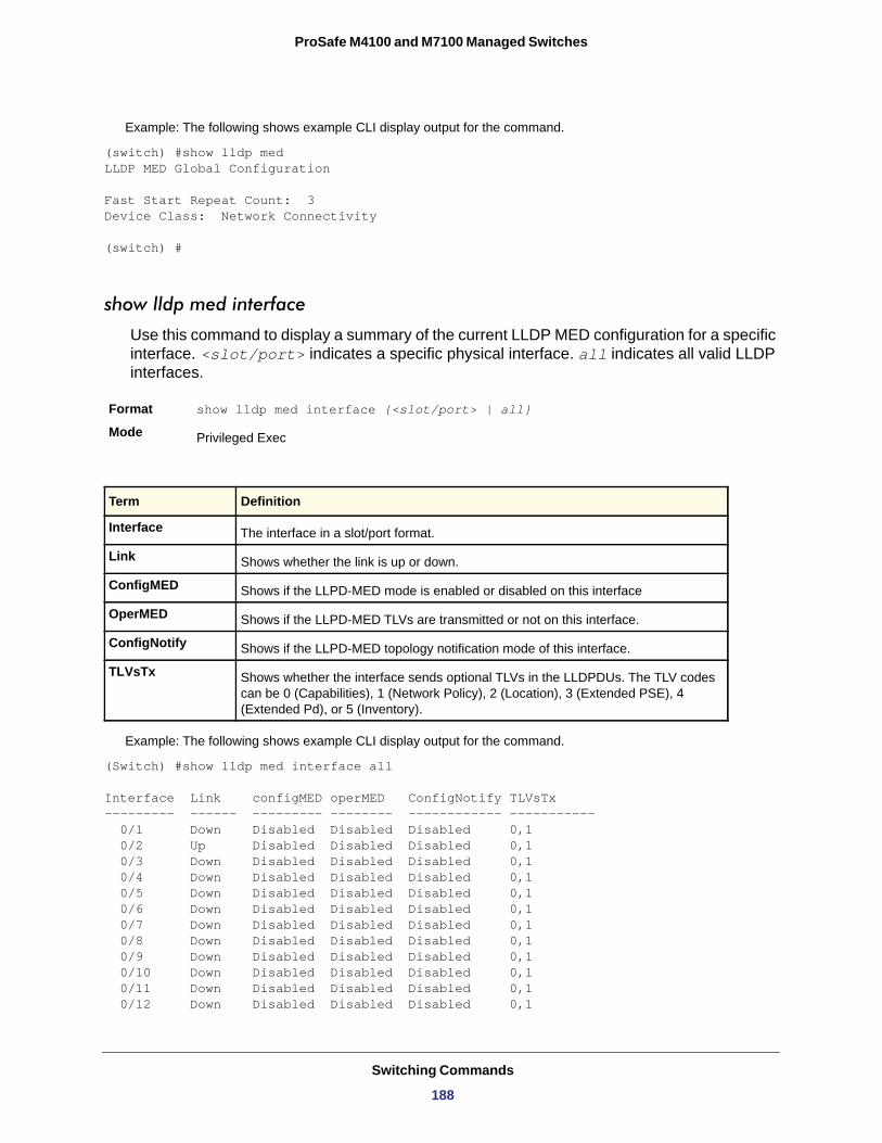
ProSafe M4100 and M7100 Managed Switches
Example: The following shows example CLI display output for the command.
(switch) #show lldp medLLDP MED Global Configuration
Fast Start Repeat Count: 3Device Class: Network Connectivity
(switch) #
show lldp med interface
Use this command to display a summary of the current LLDP MED configuration for a specific interface. <slot/port> indicates a specific physical interface. all indicates all valid LLDP interfaces.
Format show lldp med interface {<slot/port> | all}
Mode
Example: The following shows example CLI display output for the command.
(Switch) #show lldp med interface all
Interface Link configMED operMED ConfigNotify TLVsTx--------- ------ --------- -------- ------------ ----------- 0/1 Down Disabled Disabled Disabled 0,1 0/2 Up Disabled Disabled Disabled 0,1 0/3 Down Disabled Disabled Disabled 0,1 0/4 Down Disabled Disabled Disabled 0,1 0/5 Down Disabled Disabled Disabled 0,1 0/6 Down Disabled Disabled Disabled 0,1 0/7 Down Disabled Disabled Disabled 0,1 0/8 Down Disabled Disabled Disabled 0,1 0/9 Down Disabled Disabled Disabled 0,1 0/10 Down Disabled Disabled Disabled 0,1 0/11 Down Disabled Disabled Disabled 0,1 0/12 Down Disabled Disabled Disabled 0,1
Privileged Exec
Term Definition
Interface The interface in a slot/port format.
Link Shows whether the link is up or down.
ConfigMED Shows if the LLPD-MED mode is enabled or disabled on this interface
OperMED Shows if the LLPD-MED TLVs are transmitted or not on this interface.
ConfigNotify Shows if the LLPD-MED topology notification mode of this interface.
TLVsTx Shows whether the interface sends optional TLVs in the LLDPDUs. The TLV codes can be 0 (Capabilities), 1 (Network Policy), 2 (Location), 3 (Extended PSE), 4 (Extended Pd), or 5 (Inventory).
Switching Commands
188
ProSafe M4100 and M7100 Managed Switches
0/13 Down Disabled Disabled Disabled 0,1 0/14 Down Disabled Disabled Disabled 0,1
TLV Codes: 0- Capabilities, 1- Network Policy 2- Location, 3- Extended PSE 4- Extended Pd, 5- Inventory--More-- or (q)uit(Switch) #show lldp med interface 0/2
Interface Link configMED operMED ConfigNotify TLVsTx--------- ------ --------- -------- ------------ ----------- 0/2 Up Disabled Disabled Disabled 0,1
TLV Codes: 0- Capabilities, 1- Network Policy 2- Location, 3- Extended PSE 4- Extended Pd, 5- Inventory
(Routing) #
show lldp med local-device detail
This command displays detailed information about the LLDP data a specific interface transmits.
Format show lldp med local-device detail <slot/port>
Mode
Media Application Type
Vlan ID
Priority
DSCP
Unknown
Tagged
Hardware Rev
Firmware Rev
Software Rev
Serial Num
Mfg Name
Model Name
Example: The following shows example CLI display output for the command.
Privileged EXEC
Term Definition
Shows the application type. Types are unknown, voice, voicesignaling, guestvoice, guestvoicesignaling, sfotphonevoice, videoconferencing, streamingvideo, videosignaling.
Shows the VLAN id associated with a particular policy type
Shows the priority associated with a particular policy type.
Shows the DSCP associated with a particular policy type.
Indicates if the policy type is unknown. In this case, the VLAN ID, Priority and DSCP are ignored.
Indicates if the policy type is using tagged or untagged VLAN.
Shows the local hardware version.
Shows the local firmware version.
Shows the local software version.
Shows the local serial number.
Shows the manufacture name.
Shows the model name.
Switching Commands
189
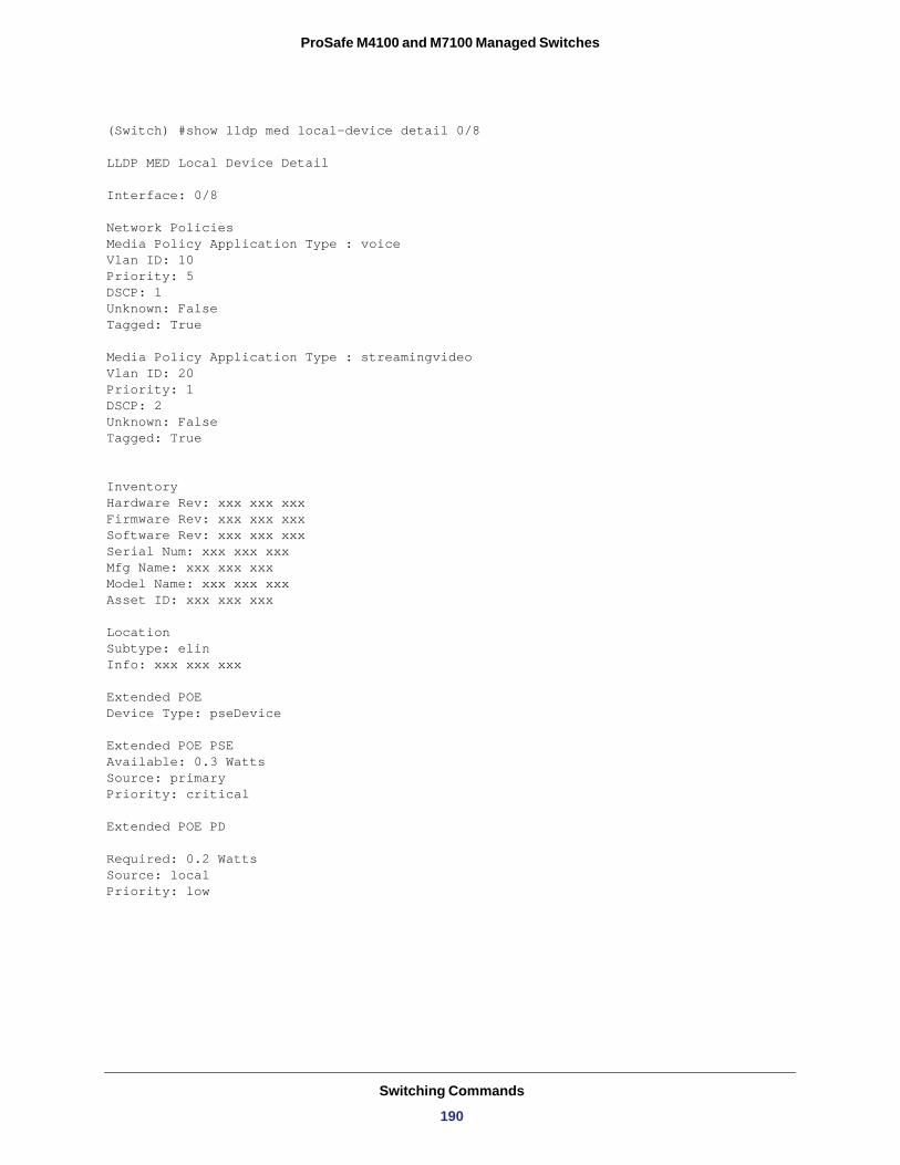
ProSafe M4100 and M7100 Managed Switches
(Switch) #show lldp med local-device detail 0/8
LLDP MED Local Device Detail
Interface: 0/8
Network PoliciesMedia Policy Application Type : voiceVlan ID: 10Priority: 5DSCP: 1Unknown: FalseTagged: True
Media Policy Application Type : streamingvideoVlan ID: 20Priority: 1DSCP: 2Unknown: FalseTagged: True
InventoryHardware Rev: xxx xxx xxxFirmware Rev: xxx xxx xxxSoftware Rev: xxx xxx xxxSerial Num: xxx xxx xxxMfg Name: xxx xxx xxx Model Name: xxx xxx xxxAsset ID: xxx xxx xxx
LocationSubtype: elinInfo: xxx xxx xxx
Extended POEDevice Type: pseDevice
Extended POE PSEAvailable: 0.3 WattsSource: primaryPriority: critical
Extended POE PD
Required: 0.2 WattsSource: localPriority: low
Switching Commands
190
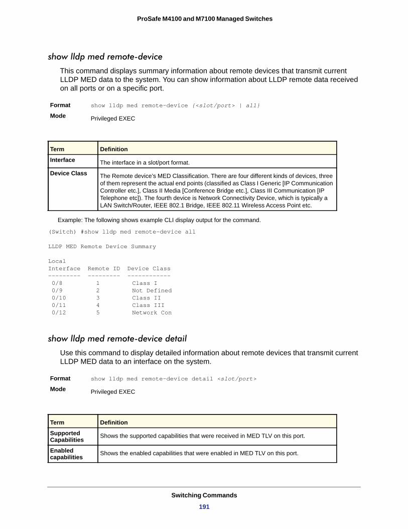
ProSafe M4100 and M7100 Managed Switches
show lldp med remote-device
This command displays summary information about remote devices that transmit current LLDP MED data to the system. You can show information about LLDP remote data received on all ports or on a specific port.
Format show lldp med remote-device {<slot/port> | all}
Mode
Example: The following shows example CLI display output for the command.
(Switch) #show lldp med remote-device all
LLDP MED Remote Device Summary
Local Interface Remote ID Device Class --------- --------- ------------ 0/8 1 Class I 0/9 2 Not Defined 0/10 3 Class II 0/11 4 Class III 0/12 5 Network Con
show lldp med remote-device detail
Use this command to display detailed information about remote devices that transmit current LLDP MED data to an interface on the system.
Format show lldp med remote-device detail <slot/port>
Mode
Privileged EXEC
Term Definition
Interface The interface in a slot/port format.
Device Class The Remote device’s MED Classification. There are four different kinds of devices, three of them represent the actual end points (classified as Class I Generic [IP Communication Controller etc.], Class II Media [Conference Bridge etc.], Class III Communication [IP Telephone etc]). The fourth device is Network Connectivity Device, which is typically a LAN Switch/Router, IEEE 802.1 Bridge, IEEE 802.11 Wireless Access Point etc.
Privileged EXEC
Term Definition
Supported Capabilities Shows the supported capabilities that were received in MED TLV on this port.
Enabled capabilities Shows the enabled capabilities that were enabled in MED TLV on this port.
Switching Commands
191
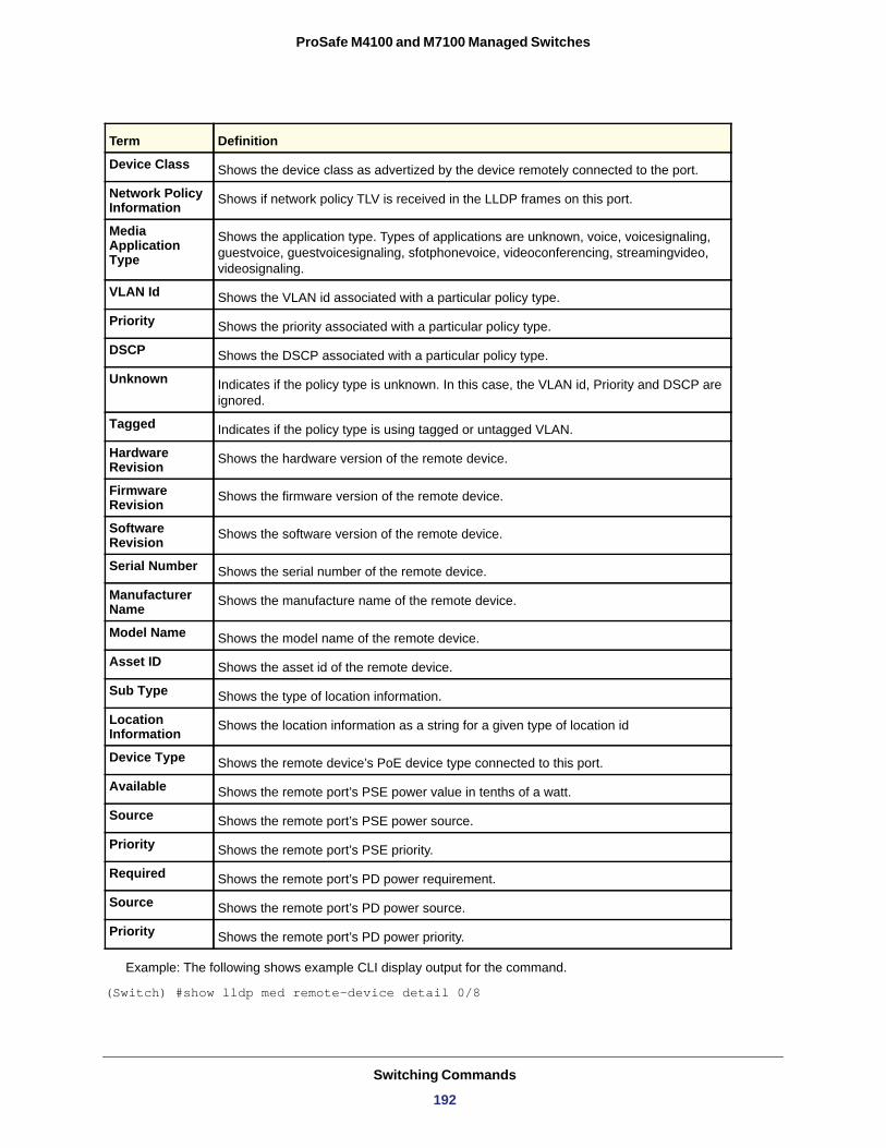
ProSafe M4100 and M7100 Managed Switches
Example: The following shows example CLI display output for the command.
(Switch) #show lldp med remote-device detail 0/8
Device Class Shows the device class as advertized by the device remotely connected to the port.
Network Policy Information Shows if network policy TLV is received in the LLDP frames on this port.
Media Application Type
Shows the application type. Types of applications are unknown, voice, voicesignaling, guestvoice, guestvoicesignaling, sfotphonevoice, videoconferencing, streamingvideo, videosignaling.
VLAN Id Shows the VLAN id associated with a particular policy type.
Priority Shows the priority associated with a particular policy type.
DSCP Shows the DSCP associated with a particular policy type.
Unknown Indicates if the policy type is unknown. In this case, the VLAN id, Priority and DSCP are ignored.
Tagged Indicates if the policy type is using tagged or untagged VLAN.
Hardware Revision Shows the hardware version of the remote device.
Firmware Revision Shows the firmware version of the remote device.
Software Revision Shows the software version of the remote device.
Serial Number Shows the serial number of the remote device.
Manufacturer Name Shows the manufacture name of the remote device.
Model Name Shows the model name of the remote device.
Asset ID Shows the asset id of the remote device.
Sub Type Shows the type of location information.
Location Information Shows the location information as a string for a given type of location id
Device Type Shows the remote device’s PoE device type connected to this port.
Available Shows the remote port’s PSE power value in tenths of a watt.
Source Shows the remote port’s PSE power source.
Priority Shows the remote port’s PSE priority.
Required Shows the remote port’s PD power requirement.
Source Shows the remote port’s PD power source.
Priority Shows the remote port’s PD power priority.
Term Definition
Switching Commands
192
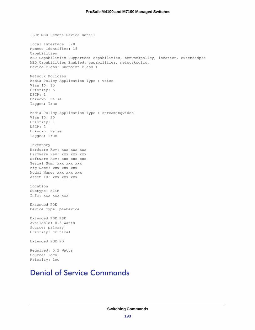
ProSafe M4100 and M7100 Managed Switches
LLDP MED Remote Device Detail
Local Interface: 0/8Remote Identifier: 18CapabilitiesMED Capabilities Supported: capabilities, networkpolicy, location, extendedpseMED Capabilities Enabled: capabilities, networkpolicyDevice Class: Endpoint Class I
Network PoliciesMedia Policy Application Type : voiceVlan ID: 10Priority: 5DSCP: 1Unknown: FalseTagged: True
Media Policy Application Type : streamingvideoVlan ID: 20Priority: 1DSCP: 2Unknown: FalseTagged: True
InventoryHardware Rev: xxx xxx xxxFirmware Rev: xxx xxx xxxSoftware Rev: xxx xxx xxxSerial Num: xxx xxx xxxMfg Name: xxx xxx xxx Model Name: xxx xxx xxxAsset ID: xxx xxx xxx
LocationSubtype: elinInfo: xxx xxx xxx
Extended POEDevice Type: pseDevice
Extended POE PSEAvailable: 0.3 WattsSource: primaryPriority: critical
Extended POE PD
Required: 0.2 WattsSource: localPriority: low
Denial of Service Commands
Switching Commands
193
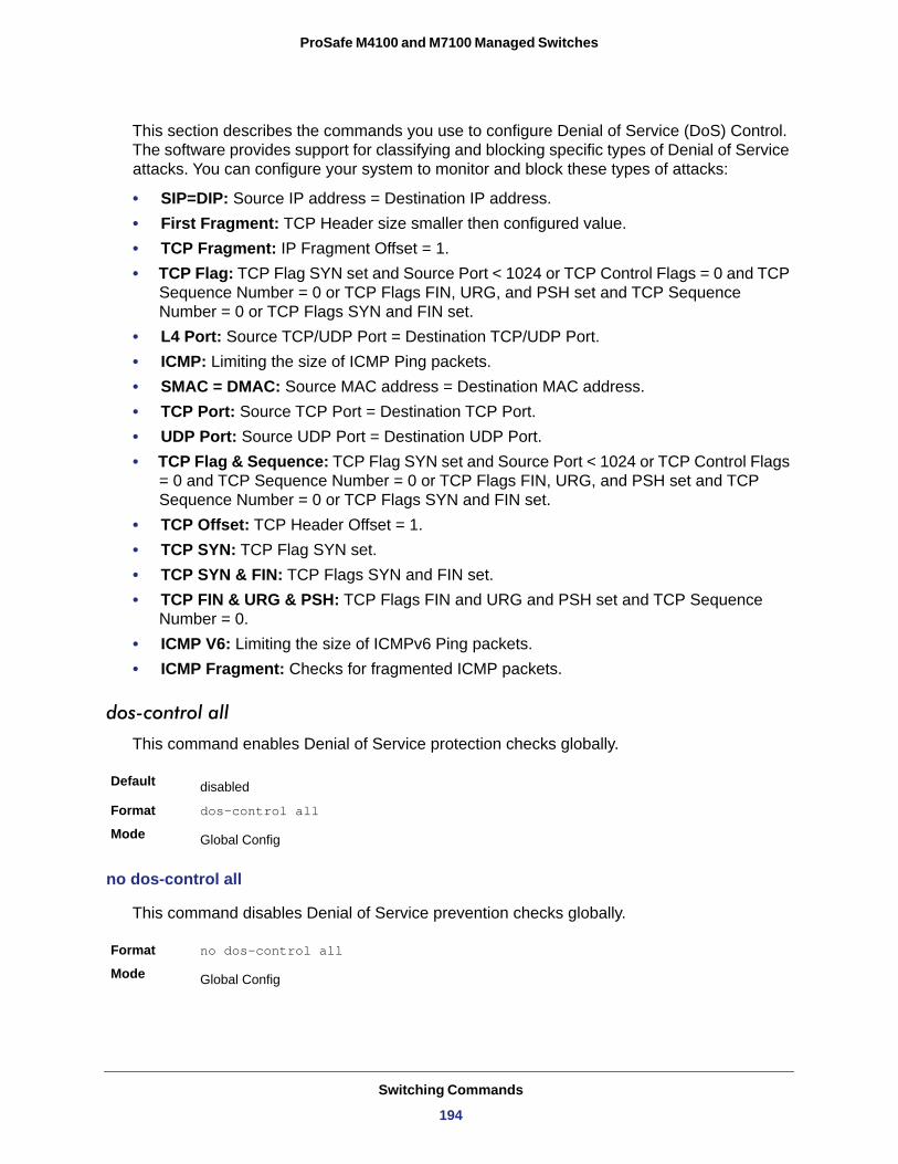
ProSafe M4100 and M7100 Managed Switches
This section describes the commands you use to configure Denial of Service (DoS) Control. The software provides support for classifying and blocking specific types of Denial of Service attacks. You can configure your system to monitor and block these types of attacks:
• SIP=DIP: Source IP address = Destination IP address.• First Fragment: TCP Header size smaller then configured value.• TCP Fragment: IP Fragment Offset = 1.• TCP Flag: TCP Flag SYN set and Source Port < 1024 or TCP Control Flags = 0 and TCP
Sequence Number = 0 or TCP Flags FIN, URG, and PSH set and TCP Sequence Number = 0 or TCP Flags SYN and FIN set.
• L4 Port: Source TCP/UDP Port = Destination TCP/UDP Port.• ICMP: Limiting the size of ICMP Ping packets.• SMAC = DMAC: Source MAC address = Destination MAC address.• TCP Port: Source TCP Port = Destination TCP Port.• UDP Port: Source UDP Port = Destination UDP Port.• TCP Flag & Sequence: TCP Flag SYN set and Source Port < 1024 or TCP Control Flags
= 0 and TCP Sequence Number = 0 or TCP Flags FIN, URG, and PSH set and TCP Sequence Number = 0 or TCP Flags SYN and FIN set.
• TCP Offset: TCP Header Offset = 1.• TCP SYN: TCP Flag SYN set.• TCP SYN & FIN: TCP Flags SYN and FIN set.• TCP FIN & URG & PSH: TCP Flags FIN and URG and PSH set and TCP Sequence
Number = 0.• ICMP V6: Limiting the size of ICMPv6 Ping packets.• ICMP Fragment: Checks for fragmented ICMP packets.
dos-control all
This command enables Denial of Service protection checks globally.
Default
Format dos-control all
Mode
no dos-control all
This command disables Denial of Service prevention checks globally.
Format no dos-control all
Mode
disabled
Global Config
Global Config
Switching Commands
194
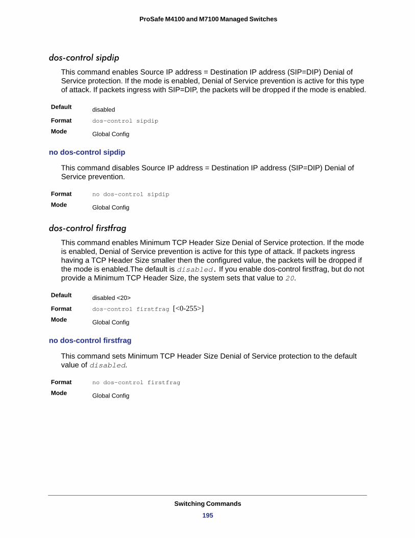
ProSafe M4100 and M7100 Managed Switches
dos-control sipdip
This command enables Source IP address = Destination IP address (SIP=DIP) Denial of Service protection. If the mode is enabled, Denial of Service prevention is active for this type of attack. If packets ingress with SIP=DIP, the packets will be dropped if the mode is enabled.
Default
Format dos-control sipdip
Mode
no dos-control sipdip
This command disables Source IP address = Destination IP address (SIP=DIP) Denial of Service prevention.
Format no dos-control sipdip
Mode
dos-control firstfrag
This command enables Minimum TCP Header Size Denial of Service protection. If the mode is enabled, Denial of Service prevention is active for this type of attack. If packets ingress having a TCP Header Size smaller then the configured value, the packets will be dropped if the mode is enabled.The default is disabled. If you enable dos-control firstfrag, but do not provide a Minimum TCP Header Size, the system sets that value to 20.
Default
Format dos-control firstfrag [<0-255>]Mode
no dos-control firstfrag
This command sets Minimum TCP Header Size Denial of Service protection to the default value of disabled.
Format no dos-control firstfrag
Mode
disabled
Global Config
Global Config
disabled <20>
Global Config
Global Config
Switching Commands
195
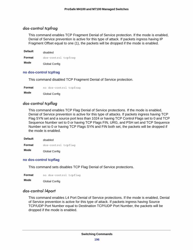
ProSafe M4100 and M7100 Managed Switches
dos-control tcpfrag
This command enables TCP Fragment Denial of Service protection. If the mode is enabled, Denial of Service prevention is active for this type of attack. If packets ingress having IP Fragment Offset equal to one (1), the packets will be dropped if the mode is enabled.
Default
Format dos-control tcpfrag
Mode
no dos-control tcpfrag
This command disabled TCP Fragment Denial of Service protection.
Format no dos-control tcpfrag
Mode
dos-control tcpflag
This command enables TCP Flag Denial of Service protections. If the mode is enabled, Denial of Service prevention is active for this type of attacks. If packets ingress having TCP Flag SYN set and a source port less than 1024 or having TCP Control Flags set to 0 and TCP Sequence Number set to 0 or having TCP Flags FIN, URG, and PSH set and TCP Sequence Number set to 0 or having TCP Flags SYN and FIN both set, the packets will be dropped if the mode is enabled.
Default
Format dos-control tcpflag
Mode
no dos-control tcpflag
This command sets disables TCP Flag Denial of Service protections.
Format no dos-control tcpflag
Mode
dos-control l4port
This command enables L4 Port Denial of Service protections. If the mode is enabled, Denial of Service prevention is active for this type of attack. If packets ingress having Source TCP/UDP Port Number equal to Destination TCP/UDP Port Number, the packets will be dropped if the mode is enabled.
disabled
Global Config
Global Config
disabled
Global Config
Global Config
Switching Commands
196
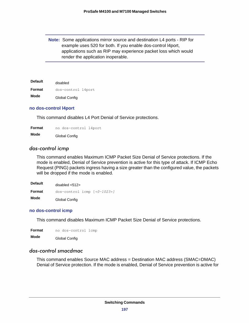
ProSafe M4100 and M7100 Managed Switches
Note: Some applications mirror source and destination L4 ports - RIP for example uses 520 for both. If you enable dos-control l4port, applications such as RIP may experience packet loss which would render the application inoperable.
no dos-control l4port
This command disables L4 Port Denial of Service protections.
Format no dos-control l4port
Mode
dos-control icmp
This command enables Maximum ICMP Packet Size Denial of Service protections. If the mode is enabled, Denial of Service prevention is active for this type of attack. If ICMP Echo Request (PING) packets ingress having a size greater than the configured value, the packets will be dropped if the mode is enabled.
Default
Format dos-control icmp [<0-1023>]
Mode
no dos-control icmp
This command disables Maximum ICMP Packet Size Denial of Service protections.
Format no dos-control icmp
Mode
dos-control smacdmac
This command enables Source MAC address = Destination MAC address (SMAC=DMAC) Denial of Service protection. If the mode is enabled, Denial of Service prevention is active for
Default disabled
Format dos-control l4port
Mode Global Config
Global Config
disabled <512>
Global Config
Global Config
Switching Commands
197
ProSafe M4100 and M7100 Managed Switches
this type of attack. If packets ingress with SMAC=DMAC, the packets will be dropped if the mode is enabled.
Default
Format dos-control smacdmac
Mode
no dos-control smacdmac
This command disables Source MAC address = Destination MAC address (SMAC=DMAC) Denial of Service protection.
Format no dos-control smacdmac
Mode
dos-control tcpport
This command enables TCP L4 source = destination port number (Source TCP Port =Destination TCP Port) Denial of Service protection. If the mode is enabled, Denial of Service prevention is active for this type of attack. If packets ingress with Source TCP Port =Destination TCP Port, the packets will be dropped if the mode is enabled.
Default
Format dos-control tcpport
Mode
no dos-control tcpport
This command disables TCP L4 source = destination port number (Source TCP Port =Destination TCP Port) Denial of Service protection.
Format no dos-control smacdmac
Mode
dos-control udpport
This command enables UDP L4 source = destination port number (Source UDP Port =Destination UDP Port) Denial of Service protection. If the mode is enabled, Denial of Service prevention is active for this type of attack. If packets ingress with Source UDP Port =Destination UDP Port, the packets will be dropped if the mode is enabled.
Default
Format dos-control udppport
Mode
disabled
Global Config
Global Config
disabled
Global Config
Global Config
disabled
Global Config
Switching Commands
198
ProSafe M4100 and M7100 Managed Switches
no dos-control udpport
This command disables UDP L4 source = destination port number (Source UDP Port =Destination UDP Port) Denial of Service protection.
Format no dos-control udppport
Mode
dos-control tcpflagseq
This command enables TCP Flag and Sequence Denial of Service protections. If the mode is enabled, Denial of Service prevention is active for this type of attack. If packets ingress having TCP Flag SYN set and a source port less than 1024 or having TCP Control Flags set to 0 and TCP Sequence Number set to 0 or having TCP Flags FIN, URG, and PSH set and TCP Sequence Number set to 0 or having TCP Flags SYN and FIN both set, the packets will be dropped if the mode is enabled.
Default
Format dos-control tcpflagseq
Mode
no dos-control tcpflagseq
This command sets disables TCP Flag and Sequence Denial of Service protection.
Format no dos-control tcpflagseq
Mode
dos-control tcpoffset
This command enables TCP Offset Denial of Service protection. If the mode is enabled, Denial of Service prevention is active for this type of attack. If packets ingress having TCP Header Offset equal to one (1), the packets will be dropped if the mode is enabled.
Default
Format dos-control tcpoffset
Mode
no dos-control tcpoffset
This command disabled TCP Offset Denial of Service protection.
Format no dos-control tcpoffset
Mode
Global Config
disabled
Global Config
Global Config
disabled
Global Config
Global Config
Switching Commands
199
ProSafe M4100 and M7100 Managed Switches
dos-control tcpsyn
This command enables TCP SYN and L4 source = 0-1023 Denial of Service protection. If the mode is enabled, Denial of Service prevention is active for this type of attack. If packets ingress having TCP flag SYN set and an L4 source port from 0 to 1023, the packets will be dropped if the mode is enabled.
Default
Format dos-control tcpsyn
Mode
no dos-control tcpsyn
This command sets disables TCP SYN and L4 source = 0-1023 Denial of Service protection.
Format no dos-control tcpsyn
Mode
dos-control tcpsynfin
This command enables TCP SYN and FIN Denial of Service protection. If the mode is enabled, Denial of Service prevention is active for this type of attack. If packets ingress having TCP flags SYN and FIN set, the packets will be dropped if the mode is enabled.
Default
Format dos-control tcpsynfin
Mode
no dos-control tcpsynfin
This command sets disables TCP SYN & FIN Denial of Service protection.
Format no dos-control tcpsynfin
Mode
dos-control tcpfinurgpsh
This command enables TCP FIN and URG and PSH and SEQ=0 checking Denial of Service protections. If the mode is enabled, Denial of Service prevention is active for this type of attack. If packets ingress having TCP FIN, URG, and PSH all set and TCP Sequence Number set to 0, the packets will be dropped if the mode is enabled.
disabled
Global Config
Global Config
disabled
Global Config
Global Config
Default disabled
Switching Commands
200
ProSafe M4100 and M7100 Managed Switches
no dos-control tcpfinurgpsh
This command sets disables TCP FIN and URG and PSH and SEQ=0 checking Denial of Service protections.
Format no dos-control tcpfinurgpsh
Mode
dos-control icmpv4
This command enables Maximum ICMPv4 Packet Size Denial of Service protections. If the mode is enabled, Denial of Service prevention is active for this type of attack. If ICMPv4 Echo Request (PING) packets ingress having a size greater than the configured value, the packets will be dropped if the mode is enabled.
Default
Format dos-control icmpv4 <0-16384>
Mode
no dos-control icmpv4
This command disables Maximum ICMP Packet Size Denial of Service protections.
Format no dos-control icmpv4
Mode
dos-control icmpv6
This command enables Maximum ICMPv6 Packet Size Denial of Service protections. If the mode is enabled, Denial of Service prevention is active for this type of attack. If ICMPv6 Echo Request (PING) packets ingress having a size greater than the configured value, the packets will be dropped if the mode is enabled.
Default
Format dos-control icmpv6 <0-16384>
Mode
Format dos-control tcpfinurgpsh
Mode Global Config
Global Config
disabled <512>
Global Config
Global Config
disabled <512>
Global Config
Switching Commands
201
ProSafe M4100 and M7100 Managed Switches
no dos-control icmpv6
This command disables Maximum ICMP Packet Size Denial of Service protections.
Format no dos-control icmpv6
Mode
dos-control icmpfrag
This command enables ICMP Fragment Denial of Service protection. If the mode is enabled, Denial of Service prevention is active for this type of attack. If packets ingress having fragmented ICMP packets, the packets will be dropped if the mode is enabled.
Default
Format dos-control icmpfrag
Mode
no dos-control icmpfrag
This command disabled ICMP Fragment Denial of Service protection.
Format no dos-control icmpfrag
Mode
show dos-control
This command displays Denial of Service configuration information.
Format show dos-control
Mode
Note: Not all messages below are available in all 7000series managed switches.
Global Config
disabled
Global Config
Global Config
Privileged EXEC
Term Definition
First Fragment Mode May be enabled or disabled. The factory default is disabled.
Min TCP Hdr Size <0-255> The factory default is 20.
ICMP Mode May be enabled or disabled. The factory default is disabled.
Switching Commands
202
ProSafe M4100 and M7100 Managed Switches
MAC Database Commands
This section describes the commands you use to configure and view information about the MAC databases.
bridge aging-time
This command configures the forwarding database address aging timeout in seconds. The <seconds> parameter must be within the range of 10 to 1,000,000 seconds.
Default
Format bridge aging-time <10-1,000,000>
Mode
Max ICMPv4 Pkt Size The range is 0-1023. The factory default is 512.
Max ICMPv6 Pkt Size The range is 0-16384. The factory default is 512.
ICMP Fragment Mode May be enabled or disabled. The factory default is disabled.
L4 Port Mode May be enabled or disabled. The factory default is disabled.
TCP Port Mode May be enabled or disabled. The factory default is disabled.
UDP Port Mode May be enabled or disabled. The factory default is disabled.
SIPDIP Mode May be enabled or disabled. The factory default is disabled.
SMACDMAC Mode May be enabled or disabled. The factory default is disabled.
TCP Flag Mode May be enabled or disabled. The factory default is disabled.
TCP FIN&URG& PSH Mode May be enabled or disabled. The factory default is disabled.
TCP Flag & Sequence Mode May be enabled or disabled. The factory default is disabled.
TCP SYN Mode May be enabled or disabled. The factory default is disabled.
TCP SYN & FIN Mode May be enabled or disabled. The factory default is disabled.
TCP Fragment Mode May be enabled or disabled. The factory default is disabled.
TCP Offset Mode May be enabled or disabled. The factory default is disabled.
300
Global Config
Term Definition
Switching Commands
203
ProSafe M4100 and M7100 Managed Switches
no bridge aging-time
This command sets the forwarding database address aging timeout to the default value.
Format no bridge aging-time
Mode
show forwardingdb agetime
This command displays the timeout for address aging.
Default
Format show forwardingdb agetime
Mode
Address Aging Timeout
show mac-address-table multicast
This command displays the Multicast Forwarding Database (MFDB) information. If you enter the command with no parameter, the entire table is displayed. You can display the table entry for one MAC Address by specifying the MAC address as an optional parameter.
Format show mac-address-table multicast <macaddr>
Mode
MAC Address
Type
Component
Description
Interfaces
Forwarding Interfaces
Global Config
300s
Privileged EXEC
Term Definition
This parameter displays the address aging timeout for the associated forwarding database.
Privileged EXEC
Term Definition
A multicast MAC address for which the switch has forwarding and or filtering information. The format is two-digit hexadecimal numbers separated by colons, for example 01:23:45:67:89:AB. In an IVL system the MAC address will be displayed as a MAC address and VLAN ID combination of 8 bytes.
The type of the entry. Static entries are those that are configured by the end user. Dynamic entries are added to the table as a result of a learning process or protocol.
The component that is responsible for this entry in the Multicast Forwarding Database. Possible values are IGMP Snooping, GMRP, and Static Filtering.
The text description of this multicast table entry.
The list of interfaces that are designated for forwarding (Fwd:) and filtering (Flt:).
The resultant forwarding list is derived from combining all the component’s forwarding interfaces and removing the interfaces that are listed as the static filtering interfaces.
Switching Commands
204
ProSafe M4100 and M7100 Managed Switches
show mac-address-table stats
This command displays the Multicast Forwarding Database (MFDB) statistics.
Format show mac-address-table stats
Mode
Max MFDB Table Entries
Most MFDB Entries Since Last Reset
Current Entries
ISDP Commands
This section describes the commands you use to configure the industry standard Discovery Protocol (ISDP).
isdp run
This command enables ISDP on the switch.
Default
Format isdp run
Mode
no isdp run
This command disables ISDP on the switch.
Format no isdp run
Mode
isdp holdtime
This command configures the hold time for ISDP packets that the switch transmits. The hold time specifies how long a receiving device should store information sent in the ISDP packet before discarding it. The range is given in seconds.
Privileged EXEC
Term Definition
The total number of entries that can possibly be in the Multicast Forwarding Database table.
The largest number of entries that have been present in the Multicast Forwarding Database table. This value is also known as the MFDB high-water mark.
The current number of entries in the MFDB.
Enabled
Global Config
Global Config
Default 180 seconds
Switching Commands
205
ProSafe M4100 and M7100 Managed Switches
isdp timer
This command sets the period of time between sending new ISDP packets. The range is given in seconds.
Default
Format isdp timer <5-254>
Mode
isdp advertise-v2
This command enables the sending of ISDP version 2 packets from the device.
Default
Format isdp advertise-v2
Mode
no isdp advertise-v2
This command disables the sending of ISDP version 2 packets from the device.
Format no isdp advertise-v2
Mode
isdp enable
This command enables ISDP on the interface.
Default
Format isdp enable
Mode
no isdp enable
This command disables ISDP on the interface.
Format no isdp enable
Mode
Format isdp holdtime <10-255>
Mode Global Config
30 seconds
Global Config
Enabled
Global Config
Global Config
Enabled
Interface Config
Interface Config
Switching Commands
206
ProSafe M4100 and M7100 Managed Switches
clear isdp counters
This command clears ISDP counters.
Format clear isdp counters
Mode
clear isdp table
This command clears entries in the ISDP table.
Format clear isdp table
Mode
show isdp
This command displays global ISDP settings.
Format show isdp
Mode
Timer
Hold Time
Version 2 Advertisements
Device ID
Device ID Format Capability • serialNumber indicates that the device uses a serial number as the format for its
Device ID.• macAddress indicates that the device uses a Layer 2 MAC address as the format for
its Device ID.• other indicates that the device uses its platform-specific format as the format for its
Device ID.
Device ID Format
• serialNumber indicates that the value is in the form of an ASCII string containing the device serial number.
• macAddress indicates that the value is in the form of a Layer 2 MAC address.• other indicates that the value is in the form of a platform specific ASCII string
containing info that identifies the device. For example, ASCII string contains serialNumber appended/prepended with system name.
Privileged EXEC
Privileged EXEC
Privileged EXEC
Term Definition
The frequency with which this device sends ISDP packets. This value is given in seconds.
The length of time the receiving device should save information sent by this device. This value is given in seconds.
The setting for sending ISDPv2 packets. If disabled, version 1 packets are transmitted.
The Device ID advertised by this device. The format of this Device ID is characterized by the value of the Device ID Format object.
Indicates the Device ID format capability of the device.
Indicates the Device ID format of the device.
Switching Commands
207
ProSafe M4100 and M7100 Managed Switches
show isdp interface
This command displays ISDP settings for the specified interface.
Format show isdp interface {all | <slot/port>}
Mode
Mode
show isdp entry
This command displays ISDP entries. If the device id is specified, then only entries for that device are shown.
Format show isdp entry {all | deviceid}
Mode
Device ID
IP Addresses
Platform
Interface
Port ID
Hold Time
Version
Advertisement Version
Capability
show isdp neighbors
This command displays the list of neighboring devices.
Format show isdp neighbors [ {<slot/port> | detail} ]
Mode
Privileged EXEC
Term Definition
ISDP mode enabled/disabled status for the interface(s).
Privileged EXEC
Term Definition
The device ID associated with the neighbor which advertised the information.
The IP address(es) associated with the neighbor.
The hardware platform advertised by the neighbor.
The interface (slot/port) on which the neighbor's advertisement was received.
The port ID of the interface from which the neighbor sent the advertisement.
The hold time advertised by the neighbor.
The software version that the neighbor is running.
The version of the advertisement packet received from the neighbor.
ISDP Functional Capabilities advertised by the neighbor.
Privileged EXEC
Switching Commands
208
ProSafe M4100 and M7100 Managed Switches
Example: The following shows example CLI display output for the command.
(Switch) #show isdp neighbors detail
Device ID 0001f45f1bc0Address(es): IP Address: 10.27.7.57Capability Router Trans Bridge Switch IGMPPlatform SecureStack C2Interface 0/48Port ID ge.3.14Holdtime 131Advertisement Version 2Entry last changed time 0 days 00:01:59Version : 05.00.56
show isdp traffic
This command displays ISDP statistics.
Format
Mode
Term Definition
Device ID The device ID associated with the neighbor which advertised the information.
IP Addresses The IP addresses associated with the neighbor.
Capability ISDP functional capabilities advertised by the neighbor.
Platform The hardware platform advertised by the neighbor.
Interface The interface (slot/port) on which the neighbor's advertisement was received.
Port ID The port ID of the interface from which the neighbor sent the advertisement.
Hold Time The hold time advertised by the neighbor.
Advertisement Version The version of the advertisement packet received from the neighbor.
Entry Last Changed Time Displays when the entry was last modified.
Version The software version that the neighbor is running.
show isdp traffic
Privileged EXEC
Term Definition
ISDP Packets Received Total number of ISDP packets received
ISDP Packets Transmitted Total number of ISDP packets transmitted
ISDPv1 Packets Received Total number of ISDPv1 packets received
Switching Commands
209
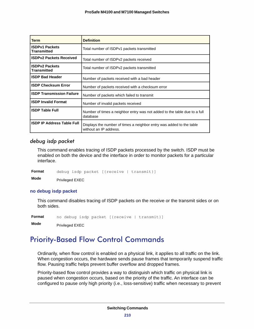
ProSafe M4100 and M7100 Managed Switches
debug isdp packet
This command enables tracing of ISDP packets processed by the switch. ISDP must be enabled on both the device and the interface in order to monitor packets for a particular interface.
Format debug isdp packet [{receive | transmit}]
Mode
no debug isdp packet
This command disables tracing of ISDP packets on the receive or the transmit sides or on both sides.
Format no debug isdp packet [{receive | transmit}]
Mode
Priority-Based Flow Control Commands
Ordinarily, when flow control is enabled on a physical link, it applies to all traffic on the link. When congestion occurs, the hardware sends pause frames that temporarily suspend traffic flow. Pausing traffic helps prevent buffer overflow and dropped frames.
Priority-based flow control provides a way to distinguish which traffic on physical link is paused when congestion occurs, based on the priority of the traffic. An interface can be configured to pause only high priority (i.e., loss-sensitive) traffic when necessary to prevent
ISDPv1 Packets Transmitted Total number of ISDPv1 packets transmitted
ISDPv2 Packets Received Total number of ISDPv2 packets received
ISDPv2 Packets Transmitted Total number of ISDPv2 packets transmitted
ISDP Bad Header Number of packets received with a bad header
ISDP Checksum Error Number of packets received with a checksum error
ISDP Transmission Failure Number of packets which failed to transmit
ISDP Invalid Format Number of invalid packets received
ISDP Table Full Number of times a neighbor entry was not added to the table due to a full database
ISDP IP Address Table Full Displays the number of times a neighbor entry was added to the table without an IP address.
Privileged EXEC
Privileged EXEC
Term Definition
Switching Commands
210
ProSafe M4100 and M7100 Managed Switches
dropped frames, while allowing traffic that has greater loss tolerance to continue to flow on the interface.
Priorities are differentiated by the priority field of the IEEE 802.1Q VLAN header, which identifies an IEEE 802.1p priority value. In NETGEAR Managed Switch, these priority values must be mapped to internal class-of-service (CoS) values.
To enable priority-based flow control for a particular CoS value on an interface:
• Ensure that VLAN tagging is enabled on the interface so that the 802.1p priority values are carried through the network.
• Ensure that 802.1p priority values are mapped to IEEE 802.1Q CoS values.• Use the datacenter-bridging priority-flow-control mode on command to enable
priority-based flow control on the interface.• Use the datacenter-bridging priority-flow-control priority command to specify the CoS
values that should be paused ("no-drop") due to greater loss sensitivity. Unless configured as "no-drop," all CoS priorities are considered nonpausable ("drop") when priority-based flow control is enabled.
When priority-flow-control is disabled, the interface defaults to the IEEE 802.3x flow control setting for the interface. When priority-based flow control is enabled, the interface will not pause any CoS unless there is at least one no-drop priority.
datacenter-bridging
Use this command to go into datacenter-bridging mode.
Format datacenter-bridging
Mode
priority-flow-control mode
Use this command to enable or disable priority-based flow control on an interface.
Format priority-flow-control mode [on | off]
Mode
Default
priority-flow-control priority
Use this command to specify the priority group(s) that should be paused when necessary to prevent dropped frames; i.e., the group to receive priority flow control. This configuration has no effect on interfaces not enabled for priority flow control.
Interface Config
Datacenter-Bridging Config
Disabled
Switching Commands
211
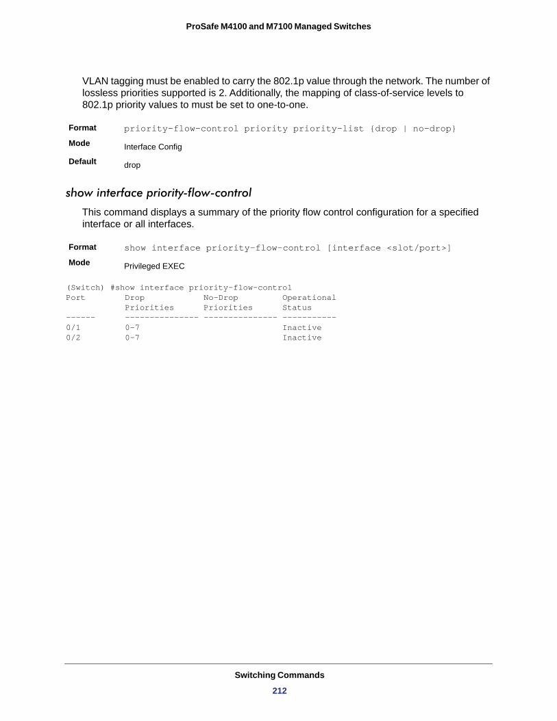
ProSafe M4100 and M7100 Managed Switches
VLAN tagging must be enabled to carry the 802.1p value through the network. The number of lossless priorities supported is 2. Additionally, the mapping of class-of-service levels to 802.1p priority values to must be set to one-to-one.
Format priority-flow-control priority priority-list {drop | no-drop}
Mode
Default
show interface priority-flow-control
This command displays a summary of the priority flow control configuration for a specified interface or all interfaces.
Format show interface priority-flow-control [interface <slot/port>]
Mode
(Switch) #show interface priority-flow-controlPort Drop No-Drop Operational Priorities Priorities Status------ --------------- --------------- -----------0/1 0-7 Inactive0/2 0-7 Inactive
Interface Config
drop
Privileged EXEC
Switching Commands
212
3
3. Multicast VLAN Registration (MVR)This chapter contains the following sections:
• About MVR • MVR Commands
213
ProSafe M4100 and M7100 Managed Switches
About MVR
Internet Group Management Protocol (IGMP) Layer 3 is widely used for IPv4 network multicasting. In Layer 2 networks, IGMP uses resources inefficiently. For example, a Layer 2 switch multicasts traffic to all ports, even if there are receivers connected to only a few ports.
To address this problem, the IGMP Snooping protocol was developed. The problem still appears, though, when receivers are in different VLANs.
MVR is intended to solve the problem of receivers in different VLANs. It uses a dedicated manually configured VLAN, called the multicast VLAN, to forward multicast traffic over a Layer 2 network with IGMP snooping.
MVR Commands
mvr
This command enables MVR.
no mvr
This command disables MVR.
mvr group
This command adds an MVR membership group. <A.B.C.D> is the IP multicast group being added.
The count is the number of incremental multicast groups being added (the first multicast group is A.B.C.D). If a count is not specified, only one multicast group is added.
Format mvr
Mode Global Config Interface Config
Default Disabled
Format no mvr
Mode Global Config Interface Config
Format mvr group <A.B.C.D> [count]
Mode Global Config
Multicast VLAN Registration (MVR)
214
ProSafe M4100 and M7100 Managed Switches
no mvr group
This command removes the MVR membership group.
mvr mode
This command changes the MVR mode type. If the mode is set to compatible, the switch does not learn multicast groups; they need to be configured by the operator as the protocol does not forward joins from the hosts to the router. To operate in this mode, the IGMP router needs to be statically configured to transmit all required multicast streams to the MVR switch. If the mode is set to dynamic, the switch learns existing multicast groups by snooping the IGMP queries from router on source ports and forwarding the IGMP joins from the hosts to the IGMP router on the multicast VLAN (with appropriate translation of the VLAN ID).
no mvr mode
This command sets the mode type to the default value.
mvr querytime
This command sets the MVR query response time.
no mvr querytime
This command sets the MVR query response time to the default value.
Format no mvr group <A.B.C.D> [count]
Mode Global Config
Format mvr mode { compatible |dynamic }
Mode Global Config
Default compatible
Format no mvr mode
Mode Global Config
Format mvr querytime<1-100>
Mode Global Config
Default 5
Format no mvr querytime
Mode Global Config
Multicast VLAN Registration (MVR)
215
ProSafe M4100 and M7100 Managed Switches
mvr vlan
This command sets the MVR multicast VLAN.
no mvr vlan
This command sets the MVR multicast VLAN to the default value.
mvr immediate
This command enables MVR immediate leave mode. MVR has two modes of operating with the IGMP Leave messages: normal leave and immediate leave:
• In normal leave mode, when a leave is received, the general IGMP query is sent from a Layer 2 switch to the receiver port, where the leave was received. Then reports are received from other interested hosts that are also connected to that port, for example, using hub.
• In immediate leave mode, when a leave is received, the switch is immediately reconfigured not to forward a specific multicast stream to the port where a message is received. This mode is used only for ports where only one client might be connected.
no mvr immediate
This command sets the MVR multicast VLAN to the default value.
Format mvr vlan <1-4094>
Mode Global Config
Default 1
Format no mvr vlan
Mode Global Config
Format mvr immediate
Mode Interface Config
Default Disabled
Format no mvr immediate
Mode Interface Config
Multicast VLAN Registration (MVR)
216
ProSafe M4100 and M7100 Managed Switches
mvr type
This command sets the MVR port type. When a port is set as source, it is the port to which the multicast traffic flows using the multicast VLAN. When a port is set to receiver, it is the port where a listening host is connected to the switch.
no mvr type
Use this command to set the MVR port type to none.
mvr vlan group
Use this command to include the port in the specific MVR group. <mVLAN> is the multicast VLAN, and <A.B.C.D> is the IP multicast group
no mvr vlan
Use this command to exclude the port from the specific MVR group.
show mvr
This command displays global MVR settings.
Format mvr type { receiver|source }
Mode Interface Config
Default none
Format no mvr type
Mode Interface Config
Format mvr vlan <mVLAN> group <A.B.C.D>
Mode Interface Config
Format no mvr vlan <mVLAN> group <A.B.C.D>
Mode Interface Config
Format show mvr
Mode Privileged EXEC
Multicast VLAN Registration (MVR)
217
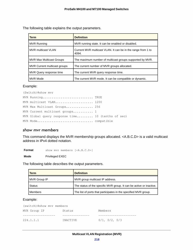
ProSafe M4100 and M7100 Managed Switches
The following table explains the output parameters.
Example:
(Switch)#show mvrMVR Running…........................... TRUEMVR multicast VLAN….................... 1200MVR Max Multicast Groups….............. 256MVR Current multicast groups….......... 1MVR Global query response time…........ 10 (tenths of sec)MVR Mode….............................. compatible
show mvr members
This command displays the MVR membership groups allocated. <A.B.C.D> is a valid multicast address in IPv4 dotted notation.
The following table describes the output parameters.
Example:
(switch)#show mvr membersMVR Group IP Status Members------------------ --------------- ---------------------224.1.1.1 INACTIVE 0/1, 0/2, 0/3
Term Definition
MVR Running MVR running state. It can be enabled or disabled.
MVR multicast VLAN Current MVR multicast VLAN. It can be in the range from 1 to 4094.
MVR Max Multicast Groups The maximum number of multicast groups supported by MVR.
MVR Current multicast groups The current number of MVR groups allocated.
MVR Query response time The current MVR query response time.
MVR Mode The current MVR mode. It can be compatible or dynamic.
Format show mvr members [<A.B.C.D>]
Mode Privileged EXEC
Term Definition
MVR Group IP MVR group multicast IP address.
Status The status of the specific MVR group. It can be active or inactive.
Members The list of ports that participates in the specified MVR group.
Multicast VLAN Registration (MVR)
218
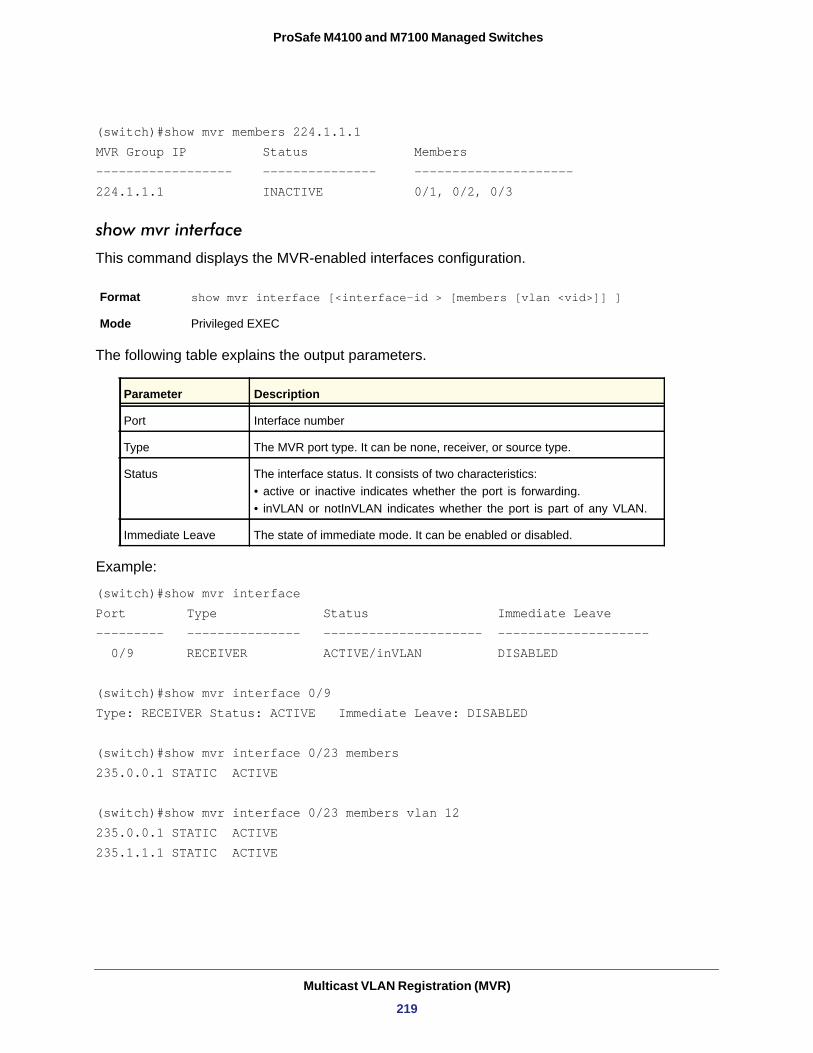
ProSafe M4100 and M7100 Managed Switches
(switch)#show mvr members 224.1.1.1MVR Group IP Status Members------------------ --------------- ---------------------224.1.1.1 INACTIVE 0/1, 0/2, 0/3
show mvr interface
This command displays the MVR-enabled interfaces configuration.
The following table explains the output parameters.
• active or inactive indicates whether the port is forwarding.• inVLAN or notInVLAN indicates whether the port is part of any VLAN.
Example:
(switch)#show mvr interfacePort Type Status Immediate Leave--------- --------------- --------------------- -------------------- 0/9 RECEIVER ACTIVE/inVLAN DISABLED
(switch)#show mvr interface 0/9Type: RECEIVER Status: ACTIVE Immediate Leave: DISABLED
(switch)#show mvr interface 0/23 members235.0.0.1 STATIC ACTIVE
(switch)#show mvr interface 0/23 members vlan 12235.0.0.1 STATIC ACTIVE235.1.1.1 STATIC ACTIVE
Format show mvr interface [<interface-id > [members [vlan <vid>]] ]
Mode Privileged EXEC
Parameter Description
Port Interface number
Type The MVR port type. It can be none, receiver, or source type.
Status The interface status. It consists of two characteristics:
Immediate Leave The state of immediate mode. It can be enabled or disabled.
Multicast VLAN Registration (MVR)
219
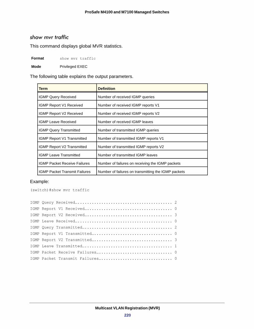
ProSafe M4100 and M7100 Managed Switches
show mvr traffic
This command displays global MVR statistics.
The following table explains the output parameters.
Example:
(switch)#show mvr traffic
IGMP Query Received…........................................ 2IGMP Report V1 Received….................................... 0
IGMP Report V2 Received….................................... 3IGMP Leave Received…........................................ 0IGMP Query Transmitted…..................................... 2IGMP Report V1 Transmitted…................................. 0IGMP Report V2 Transmitted…................................. 3IGMP Leave Transmitted…..................................... 1IGMP Packet Receive Failures…............................... 0IGMP Packet Transmit Failures….............................. 0
Format show mvr traffic
Mode Privileged EXEC
Term Definition
IGMP Query Received Number of received IGMP queries
IGMP Report V1 Received Number of received IGMP reports V1
IGMP Report V2 Received Number of received IGMP reports V2
IGMP Leave Received Number of received IGMP leaves
IGMP Query Transmitted Number of transmitted IGMP queries
IGMP Report V1 Transmitted Number of transmitted IGMP reports V1
IGMP Report V2 Transmitted Number of transmitted IGMP reports V2
IGMP Leave Transmitted Number of transmitted IGMP leaves
IGMP Packet Receive Failures Number of failures on receiving the IGMP packets
IGMP Packet Transmit Failures Number of failures on transmitting the IGMP packets
Multicast VLAN Registration (MVR)
220
4
4. Routing CommandsThis chapter describes the routing commands available in the 7000 series CLI.
Note: Some commands described in this chapter require a license. For more information, see Licensing and Command Support on page 8.
This chapter contains the following sections:
• Address Resolution Protocol (ARP) Commands • IP Routing Commands • Router Discovery Protocol Commands • Virtual LAN Routing Commands • Virtual Router Redundancy Protocol Commands • DHCP and BOOTP Relay Commands • IP Helper Commands • Open Shortest Path First (OSPF) Commands • OSPF Graceful Restart Commands • Routing Information Protocol (RIP) Commands • ICMP Throttling Commands
The commands in this chapter are in three functional groups:
• Show commands display switch settings, statistics, and other information.• Configuration commands configure features and options of the switch. Every switch
command has a show command that displays the configuration setting.• Clear commands clear some or all of the settings to factory defaults.
221
ProSafe M4100 and M7100 Managed Switches
Address Resolution Protocol (ARP) Commands
This section describes the commands you use to configure ARP and to view ARP information about the switch. ARP associates IP addresses with MAC addresses and stores the information as ARP entries in the ARP cache.
arp
This command creates an ARP entry. The value for <ipaddress> is the IP address of a device on a subnet attached to an existing routing interface. <macaddr> is a unicast MAC address for that device.
The format of the MAC address is 6 two-digit hexadecimal numbers that are separated by colons, for example 00:06:29:32:81:40.
Format arp <ipaddress> <macaddr>
Mode
no arp
This command deletes an ARP entry. The value for <arpentry> is the IP address of the interface. The value for <ipaddress> is the IP address of a device on a subnet attached to an existing routing interface. <macaddr> is a unicast MAC address for that device.
Format no arp <ipaddress> <macaddr>
Mode
ip local-proxy-arp
This command enables local-proxy-arp on interface or range of interfaces. The switch only responds if all next hops in its route to the destination are through interfaces other than the interface that received the ARP request. Enabling local proxy ARP removes this restriction..
Default
Format ip local-proxy-arp
Mode
no ip local-proxy-arp
This command disables local-proxy-arp on the interface or a range of interfaces.
Format no ip local-proxy-arp
Mode
Global Config
Global Config
disabled
Interface Config
Interface Config
Routing Commands
222
ProSafe M4100 and M7100 Managed Switches
ip proxy-arp
This command enables proxy ARP on a router interface. Without proxy ARP, a device only responds to an ARP request if the target IP address is an address configured on the interface where the ARP request arrived. With proxy ARP, the device might also respond if the target IP address is reachable. The device responds only if all next hops in its route to the destination are through interfaces other than the interface that received the ARP request.
Default
Format ip proxy-arp
Mode
no ip proxy-arp
This command disables proxy ARP on a router interface.
Format no ip proxy-arp
Mode
arp cachesize
This command configures the ARP cache size. The ARP cache size value is a platform-specific integer value. The default size also varies depending on the platform.
Format arp cachesize <platform specific integer value>
Mode
no arp cachesize
This command configures the default ARP cache size.
Format no arp cachesize
Mode
arp dynamicrenew
This command enables the ARP component to automatically renew dynamic ARP entries when they age out.
Default
Format arp dynamicrenew
Mode
enabled
Interface Config
Interface Config
Global Config
Global Config
enabled
Privileged EXEC
Routing Commands
223
ProSafe M4100 and M7100 Managed Switches
no arp dynamicrenew
This command prevents dynamic ARP entries from renewing when they age out.
Format no arp dynamicrenew
Mode
arp purge
This command causes the specified IP address to be removed from the ARP cache. Only entries of type dynamic or gateway are affected by this command.
Format arp purge <ipaddr>
Mode
arp resptime
This command configures the ARP request response time-out.
The value for <seconds> is a valid positive integer, which represents the IP ARP entry response time-out time in seconds. The range for <seconds> is between 1-10 seconds.
Default
Format arp resptime <1-10>
Mode
no arp resptime
This command configures the default ARP request response time-out.
Format no arp resptime
Mode
arp retries
This command configures the ARP count of maximum request for retries.
The value for <retries> is an integer, which represents the maximum number of requests for retries. The range for <retries> is an integer between 0-10 retries.
Default
Format arp retries <0-10>
Mode
Privileged EXEC
Privileged EXEC
1
Global Config
Global Config
4
Global Config
Routing Commands
224
ProSafe M4100 and M7100 Managed Switches
no arp retries
This command configures the default ARP count of maximum request for retries.
Format no arp retries
Mode
arp timeout
This command configures the ARP entry ageout time.
The value for <seconds> is a valid positive integer, which represents the IP ARP entry ageout time in seconds. The range for <seconds> is between 15-21600 seconds.
Default
Format arp timeout <15-21600>
Mode
no arp timeout
This command configures the default ARP entry ageout time.
Format no arp timeout
Mode
clear arp-cache
This command causes all ARP entries of type dynamic to be removed from the ARP cache. If the gateway keyword is specified, the dynamic entries of type gateway are purged as well.
Format clear arp-cache [gateway]
Mode
clear arp-switch
Use this command to clear the contents of the switch’s Address Resolution Protocol (ARP) table that contains entries learned through the Management port. To observe whether this command is successful, ping from the remote system to the DUT. Issue the show arp switch command to see the ARP entries. Then issue the clear arp-switch command and check the show arp switch entries. There will be no more arp entries.
Format clear arp-switch
Mode
Global Config
1200
Global Config
Global Config
Privileged EXEC
Privileged EXEC
Routing Commands
225
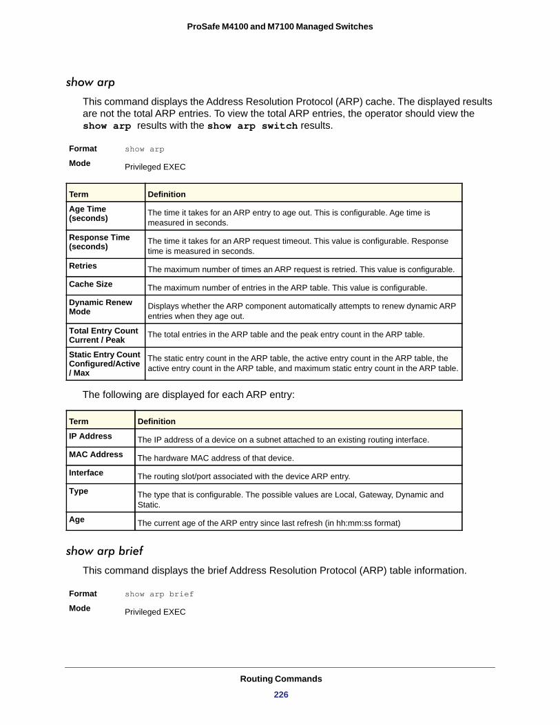
ProSafe M4100 and M7100 Managed Switches
show arp
This command displays the Address Resolution Protocol (ARP) cache. The displayed results are not the total ARP entries. To view the total ARP entries, the operator should view the show arp results with the show arp switch results.
Format show arp
Mode
Age Time (seconds)
Response Time (seconds)
Retries
Cache Size
Dynamic Renew Mode
Total Entry Count Current / Peak
Static Entry Count Configured/Active / Max
The following are displayed for each ARP entry:
IP Address
MAC Address
Interface
Type
Age
show arp brief
This command displays the brief Address Resolution Protocol (ARP) table information.
Format show arp brief
Mode
Privileged EXEC
Term Definition
The time it takes for an ARP entry to age out. This is configurable. Age time is measured in seconds.
The time it takes for an ARP request timeout. This value is configurable. Response time is measured in seconds.
The maximum number of times an ARP request is retried. This value is configurable.
The maximum number of entries in the ARP table. This value is configurable.
Displays whether the ARP component automatically attempts to renew dynamic ARP entries when they age out.
The total entries in the ARP table and the peak entry count in the ARP table.
The static entry count in the ARP table, the active entry count in the ARP table, the active entry count in the ARP table, and maximum static entry count in the ARP table.
Term Definition
The IP address of a device on a subnet attached to an existing routing interface.
The hardware MAC address of that device.
The routing slot/port associated with the device ARP entry.
The type that is configurable. The possible values are Local, Gateway, Dynamic and Static.
The current age of the ARP entry since last refresh (in hh:mm:ss format)
Privileged EXEC
Routing Commands
226
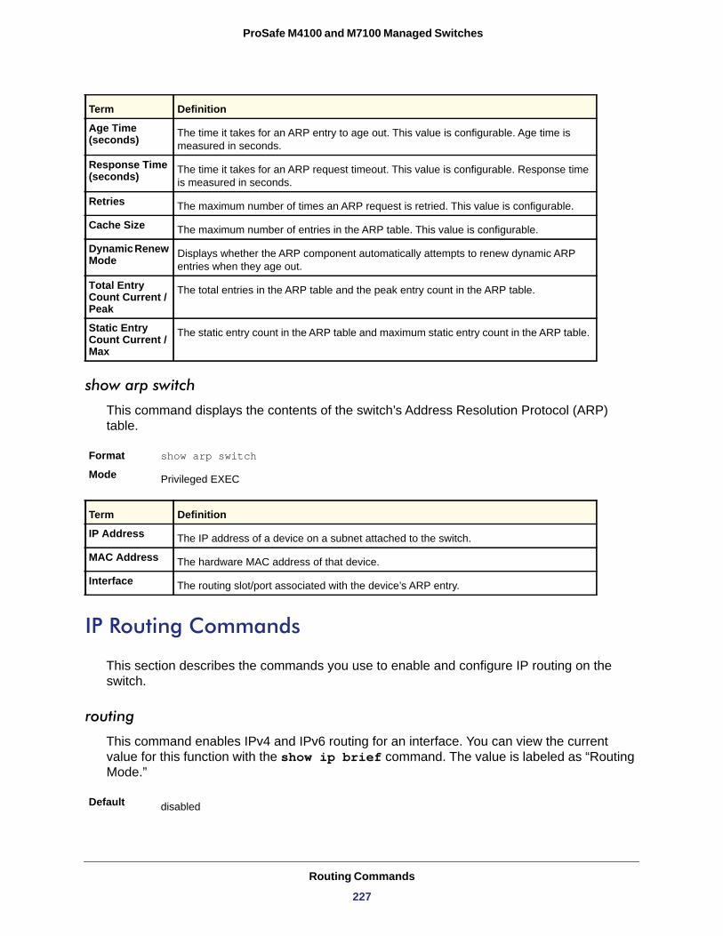
ProSafe M4100 and M7100 Managed Switches
Age Time (seconds)
Response Time (seconds)
Retries
Cache Size
Dynamic Renew Mode
Total Entry Count Current / Peak
Static Entry Count Current / Max
show arp switch
This command displays the contents of the switch’s Address Resolution Protocol (ARP) table.
Format show arp switch
Mode
IP Address
MAC Address
Interface
IP Routing Commands
This section describes the commands you use to enable and configure IP routing on the switch.
routing
This command enables IPv4 and IPv6 routing for an interface. You can view the current value for this function with the show ip brief command. The value is labeled as “Routing Mode.”
Term Definition
The time it takes for an ARP entry to age out. This value is configurable. Age time is measured in seconds.
The time it takes for an ARP request timeout. This value is configurable. Response time is measured in seconds.
The maximum number of times an ARP request is retried. This value is configurable.
The maximum number of entries in the ARP table. This value is configurable.
Displays whether the ARP component automatically attempts to renew dynamic ARP entries when they age out.
The total entries in the ARP table and the peak entry count in the ARP table.
The static entry count in the ARP table and maximum static entry count in the ARP table.
Privileged EXEC
Term Definition
The IP address of a device on a subnet attached to the switch.
The hardware MAC address of that device.
The routing slot/port associated with the device’s ARP entry.
Default disabled
Routing Commands
227
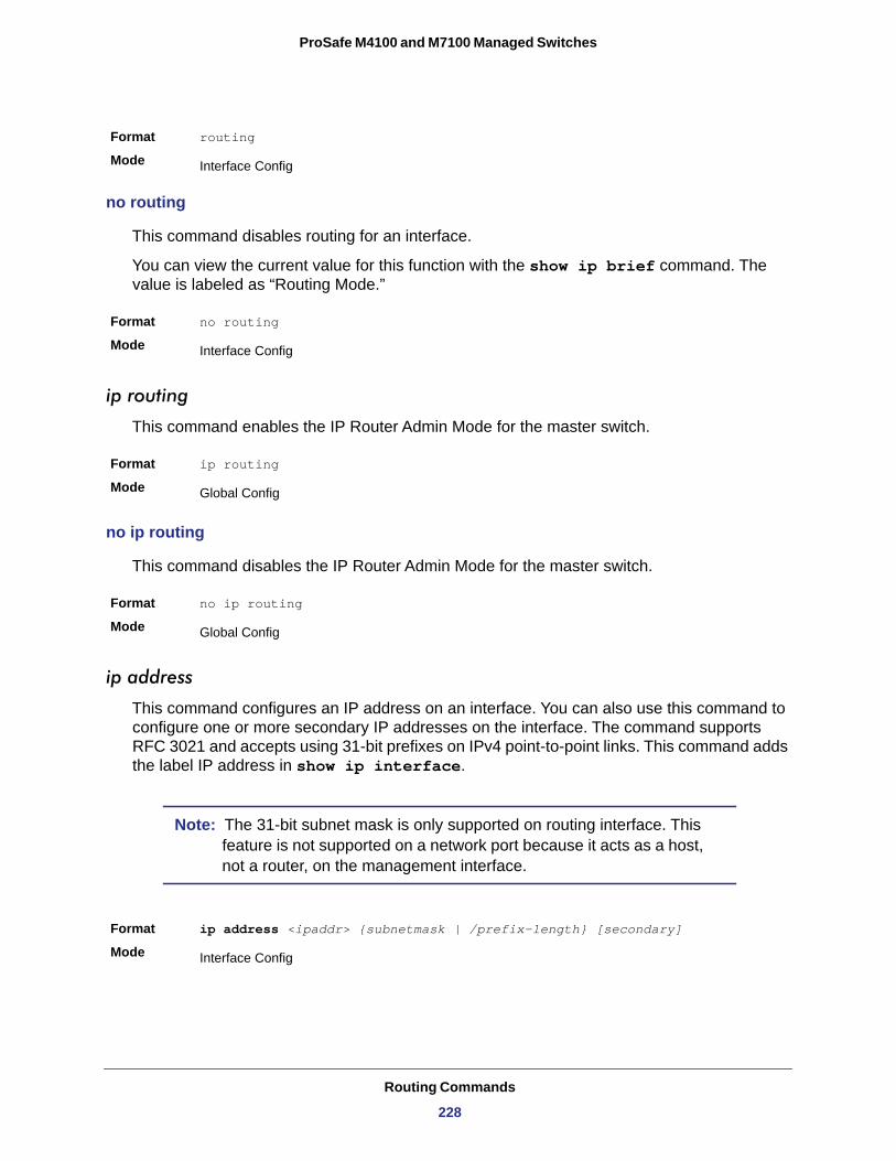
ProSafe M4100 and M7100 Managed Switches
no routing
This command disables routing for an interface.
You can view the current value for this function with the show ip brief command. The value is labeled as “Routing Mode.”
Format no routing
Mode
ip routing
This command enables the IP Router Admin Mode for the master switch.
Format ip routing
Mode
no ip routing
This command disables the IP Router Admin Mode for the master switch.
Format no ip routing
Mode
ip address
This command configures an IP address on an interface. You can also use this command to configure one or more secondary IP addresses on the interface. The command supports RFC 3021 and accepts using 31-bit prefixes on IPv4 point-to-point links. This command adds the label IP address in show ip interface.
Note: The 31-bit subnet mask is only supported on routing interface. This feature is not supported on a network port because it acts as a host, not a router, on the management interface.
Format ip address <ipaddr> {subnetmask | /prefix-length} [secondary]
Mode
Format routing
Mode Interface Config
Interface Config
Global Config
Global Config
Interface Config
Routing Commands
228
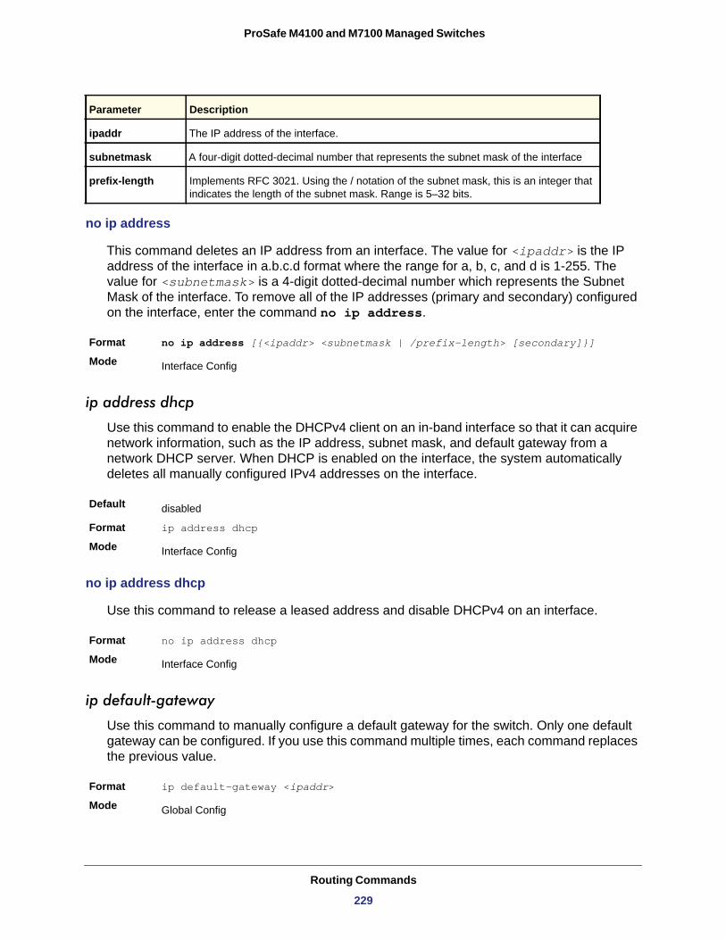
ProSafe M4100 and M7100 Managed Switches
no ip address
This command deletes an IP address from an interface. The value for <ipaddr> is the IP address of the interface in a.b.c.d format where the range for a, b, c, and d is 1-255. The value for <subnetmask> is a 4-digit dotted-decimal number which represents the Subnet Mask of the interface. To remove all of the IP addresses (primary and secondary) configured on the interface, enter the command no ip address.
Format no ip address [{<ipaddr> <subnetmask | /prefix-length> [secondary]}]
Mode
ip address dhcp
Use this command to enable the DHCPv4 client on an in-band interface so that it can acquire network information, such as the IP address, subnet mask, and default gateway from a network DHCP server. When DHCP is enabled on the interface, the system automatically deletes all manually configured IPv4 addresses on the interface.
Default
Format ip address dhcp
Mode
no ip address dhcp
Use this command to release a leased address and disable DHCPv4 on an interface.
Format no ip address dhcp
Mode
ip default-gateway
Use this command to manually configure a default gateway for the switch. Only one default gateway can be configured. If you use this command multiple times, each command replaces the previous value.
Format ip default-gateway <ipaddr>
Mode
Parameter Description
ipaddr The IP address of the interface.
subnetmask A four-digit dotted-decimal number that represents the subnet mask of the interface
prefix-length Implements RFC 3021. Using the / notation of the subnet mask, this is an integer that indicates the length of the subnet mask. Range is 5–32 bits.
Interface Config
disabled
Interface Config
Interface Config
Global Config
Routing Commands
229
ProSafe M4100 and M7100 Managed Switches
no ip default-gateway
Use this command to remove the default gateway address from the configuration.
Format no ip default-gateway <ipaddr>
Mode
release dhcp
Use this command to force the DHCPv4 client to release the leased address from the specified interface.
Format release dhcp <slot/port>
Mode
renew dhcp
Use this command to force the DHCPv4 client to immediately renew an IPv4 address lease on the specified interface.
Format renew dhcp {<slot/port>|network-port}
Mode
Note: This command can be used on in-band ports as well as network (out-of-band) port.
show dhcp lease
Use this command to display a list of IPv4 addresses currently leased from a DHCP server on a specific in-band interface or all in-band interfaces. This command does not apply to service or network ports.
Format show dhcp lease [interface <slot/port>]
Mode
Interface Config
Privileged EXEC
Privileged EXEC
Privileged EXEC
Term Definition
IP address, Subnet mask The IP address and network mask leased from the DHCP server.
DHCP Lease server The IPv4 address of the DHCP server that leased the address.
State State of the DHCPv4 Client on this interface.
DHCP transaction ID The transaction ID of the DHCPv4 Client.
Routing Commands
230
ProSafe M4100 and M7100 Managed Switches
ip route
This command configures a static route. The <ipaddr> parameter is a valid IP address, and <subnetmask> is a valid subnet mask. The <nexthopip> parameter is a valid IP address of the next hop router. Specifying Null0 as nexthop parameter adds a static reject route. The optional <preference> parameter is an integer (value from 1 to 255) that allows you to specify the preference value (sometimes called “administrative distance”) of an individual static route. Among routes to the same destination, the route with the lowest preference value is the route entered into the forwarding database. By specifying the preference of a static route, you control whether a static route is more or less preferred than routes from dynamic routing protocols. The preference also controls whether a static route is more or less preferred than other static routes to the same destination. A route with a preference of 255 cannot be used to forward traffic.
For the static routes to be visible, you must perform the following steps:
• Enable ip routing globally.• Enable ip routing for the interface. • Confirm that the associated link is also up.
Default
Format ip route <ipaddr> <subnetmask> [<nexthopip> | Null0] [<preference>]
Mode
no ip route
This command deletes a single next hop to a destination static route. If you use the <nexthopip> parameter, the next hop is deleted. If you use the <preference> value, the preference value of the static route is reset to its default.
Format no ip route <ipaddr> <subnetmask> [{<nexthopip> [<preference>] | Null0}]
Mode
Lease The time (in seconds) that the IP address was leased by the server.
Renewal The time (in seconds) when the next DHCP renew Request is sent by DHCPv4 Client to renew the leased IP address.
Rebind The time (in seconds) when the DHCP Rebind process starts.
Retry count Number of times the DHCPv4 client sends a DHCP REQUEST message before the server responds.
preference—1
Global Config
Global Config
Term Definition
Routing Commands
231
ProSafe M4100 and M7100 Managed Switches
ip route default
This command configures the default route. The value for <nexthopip> is a valid IP address of the next hop router. The <preference> is an integer value from 1 to 255. A route with a preference of 255 cannot be used to forward traffic.
Default
Format ip route default <nexthopip> [<preference>]
Mode
no ip route default
This command deletes all configured default routes. If the optional <nexthopip> parameter is designated, the specific next hop is deleted from the configured default route and if the optional preference value is designated, the preference of the configured default route is reset to its default.
Format no ip route default [{<nexthopip> | <preference>}]
Mode
ip route distance
This command sets the default distance (preference) for static routes. Lower route distance values are preferred when determining the best route. The ip route and ip route default commands allow you to optionally set the distance (preference) of an individual static route. The default distance is used when no distance is specified in these commands. Changing the default distance does not update the distance of existing static routes, even if they were assigned the original default distance. The new default distance will only be applied to static routes created after invoking the ip route distance command.
Default
Format ip route distance <1-255>
Mode
no ip route distance
This command sets the default static route preference value in the router. Lower route preference values are preferred when determining the best route.
Format no ip route distance
Mode
preference—1
Global Config
Global Config
1
Global Config
Global Config
Routing Commands
232
ProSafe M4100 and M7100 Managed Switches
ip netdirbcast
This command enables the forwarding of network-directed broadcasts. When enabled, network directed broadcasts are forwarded. When disabled they are dropped.
Default
Format ip netdirbcast
Mode
no ip netdirbcast
This command disables the forwarding of network-directed broadcasts. When disabled, network directed broadcasts are dropped.
Format no ip netdirbcast
Mode
ip mtu
This command sets the IP maximum transmission unit (MTU) on a routing interface. The IP MTU is the size of the largest IP packet that can be transmitted on the interface without fragmentation. The software currently does not fragment IP packets.
• Packets forwarded in hardware ignore the IP MTU. • Packets forwarded in software are dropped if they exceed the IP MTU of the outgoing
interface.
Packets originated on the router, such as OSPF packets, might be fragmented by the IP stack. The IP stack uses its default IP MTU and ignores the value set using the ip mtu command.
OSPF advertises the IP MTU in the Database Description packets it sends to its neighbors during database exchange. If two OSPF neighbors advertise different IP MTUs, they will not form an adjacency. (unless OSPF has been instructed to ignore differences in IP MTU with the ip ospf mtu-ignore command.)
Note: The IP MTU size refers to the maximum size of the IP packet (IP Header + IP payload). It does not include any extra bytes that might be required for Layer-2 headers. To receive and process packets, the Ethernet MTU (see mtu on page 23) must take into account the size of the Ethernet header.
disabled
Interface Config
Interface Config
Default 1500 bytes
Routing Commands
233
ProSafe M4100 and M7100 Managed Switches
no ip mtu
This command resets the ip mtu to the default value.
Format no ip mtu <mtu>
Mode
encapsulation
This command configures the link layer encapsulation type for the packet. The encapsulation type can be ethernet or snap.
Default
Format encapsulation {ethernet | snap}
Mode
Note: Routed frames are always Ethernet encapsulated when a frame is routed to a VLAN.
clear ip route all
This command removes all the route entries learned over the network.
Format clear ip route all
Mode
Protocol
Total Number of Routes
clear ip route counters
This command resets to zero the IPv4 routing table counters reported in show ip route summary. The command resets only the event counters. Counters that report the current state of the routing table, such as the number of routes of each type, are not reset.
Format clear ip route counters
Mode
Format ip mtu <68-9198>
Mode Interface Config
Interface Config
ethernet
Interface Config
Privileged EXEC
Tells which protocol added the specified route. The possibilities are: local, static, OSPF, or RIP.
The total number of routes.
Privileged EXEC
Routing Commands
234
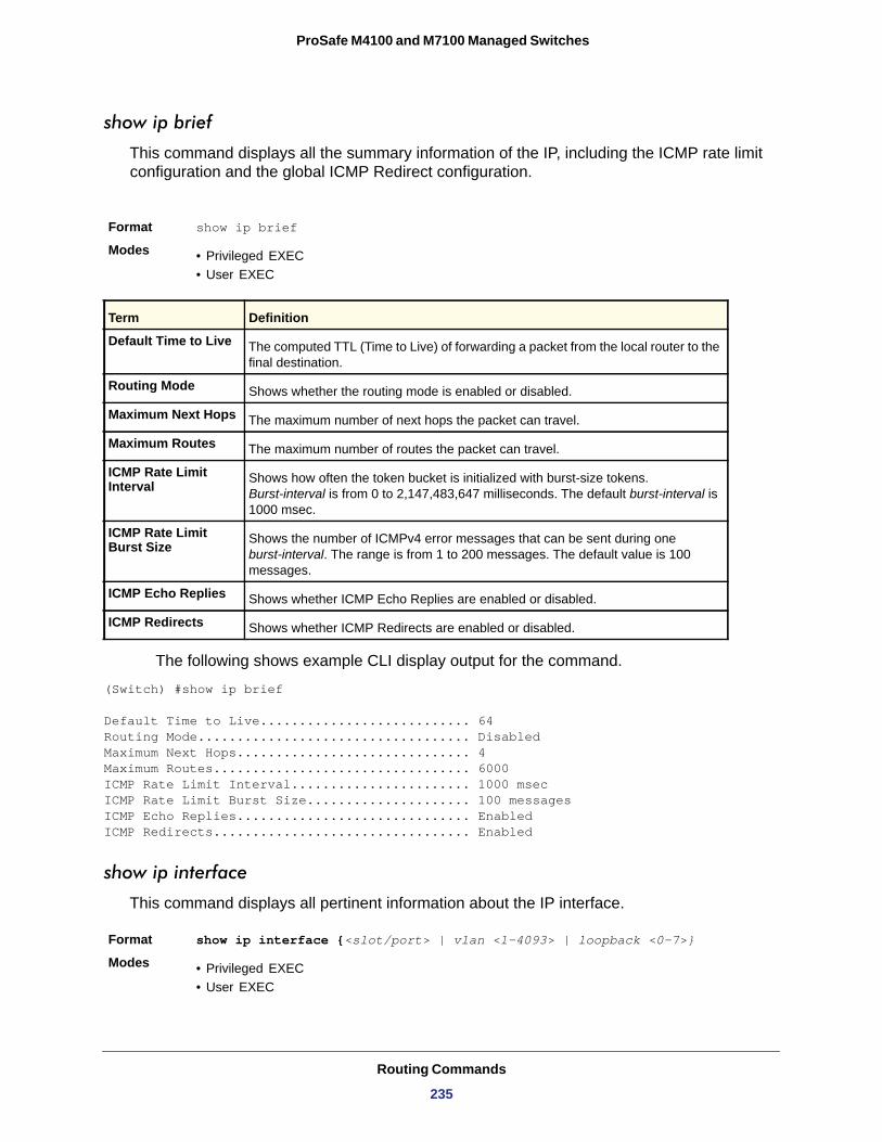
ProSafe M4100 and M7100 Managed Switches
show ip brief
This command displays all the summary information of the IP, including the ICMP rate limit configuration and the global ICMP Redirect configuration.
The following shows example CLI display output for the command.
(Switch) #show ip brief
Default Time to Live........................... 64Routing Mode................................... DisabledMaximum Next Hops.............................. 4Maximum Routes................................. 6000ICMP Rate Limit Interval....................... 1000 msecICMP Rate Limit Burst Size..................... 100 messagesICMP Echo Replies.............................. EnabledICMP Redirects................................. Enabled
show ip interface
This command displays all pertinent information about the IP interface.
Format show ip interface {<slot/port> | vlan <1-4093> | loopback <0-7>}
Modes • Privileged EXEC• User EXEC
Format show ip brief
Modes • Privileged EXEC• User EXEC
Term Definition
Default Time to Live The computed TTL (Time to Live) of forwarding a packet from the local router to the final destination.
Routing Mode Shows whether the routing mode is enabled or disabled.
Maximum Next Hops The maximum number of next hops the packet can travel.
Maximum Routes The maximum number of routes the packet can travel.
ICMP Rate Limit Interval Shows how often the token bucket is initialized with burst-size tokens.
Burst-interval is from 0 to 2,147,483,647 milliseconds. The default burst-interval is 1000 msec.
ICMP Rate Limit Burst Size Shows the number of ICMPv4 error messages that can be sent during one
burst-interval. The range is from 1 to 200 messages. The default value is 100 messages.
ICMP Echo Replies Shows whether ICMP Echo Replies are enabled or disabled.
ICMP Redirects Shows whether ICMP Redirects are enabled or disabled.
Routing Commands
235
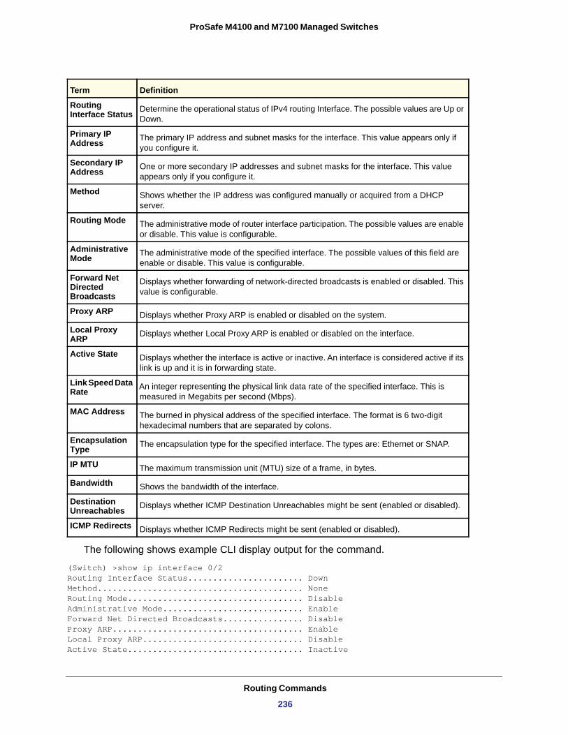
ProSafe M4100 and M7100 Managed Switches
Routing Interface Status
Primary IP Address
Secondary IP Address
Method
Routing Mode
Administrative Mode
Forward Net Directed Broadcasts
Proxy ARP
Local Proxy ARP
Active State
Link Speed Data Rate
MAC Address
Encapsulation Type
IP MTU
Bandwidth
Destination Unreachables
ICMP Redirects
The following shows example CLI display output for the command.
(Switch) >show ip interface 0/2Routing Interface Status....................... DownMethod......................................... NoneRouting Mode................................... DisableAdministrative Mode............................ EnableForward Net Directed Broadcasts................ DisableProxy ARP...................................... EnableLocal Proxy ARP................................ DisableActive State................................... Inactive
Term Definition
Determine the operational status of IPv4 routing Interface. The possible values are Up or Down.
The primary IP address and subnet masks for the interface. This value appears only if you configure it.
One or more secondary IP addresses and subnet masks for the interface. This value appears only if you configure it.
Shows whether the IP address was configured manually or acquired from a DHCP server.
The administrative mode of router interface participation. The possible values are enable or disable. This value is configurable.
The administrative mode of the specified interface. The possible values of this field are enable or disable. This value is configurable.
Displays whether forwarding of network-directed broadcasts is enabled or disabled. This value is configurable.
Displays whether Proxy ARP is enabled or disabled on the system.
Displays whether Local Proxy ARP is enabled or disabled on the interface.
Displays whether the interface is active or inactive. An interface is considered active if its link is up and it is in forwarding state.
An integer representing the physical link data rate of the specified interface. This is measured in Megabits per second (Mbps).
The burned in physical address of the specified interface. The format is 6 two-digit hexadecimal numbers that are separated by colons.
The encapsulation type for the specified interface. The types are: Ethernet or SNAP.
The maximum transmission unit (MTU) size of a frame, in bytes.
Shows the bandwidth of the interface.
Displays whether ICMP Destination Unreachables might be sent (enabled or disabled).
Displays whether ICMP Redirects might be sent (enabled or disabled).
Routing Commands
236
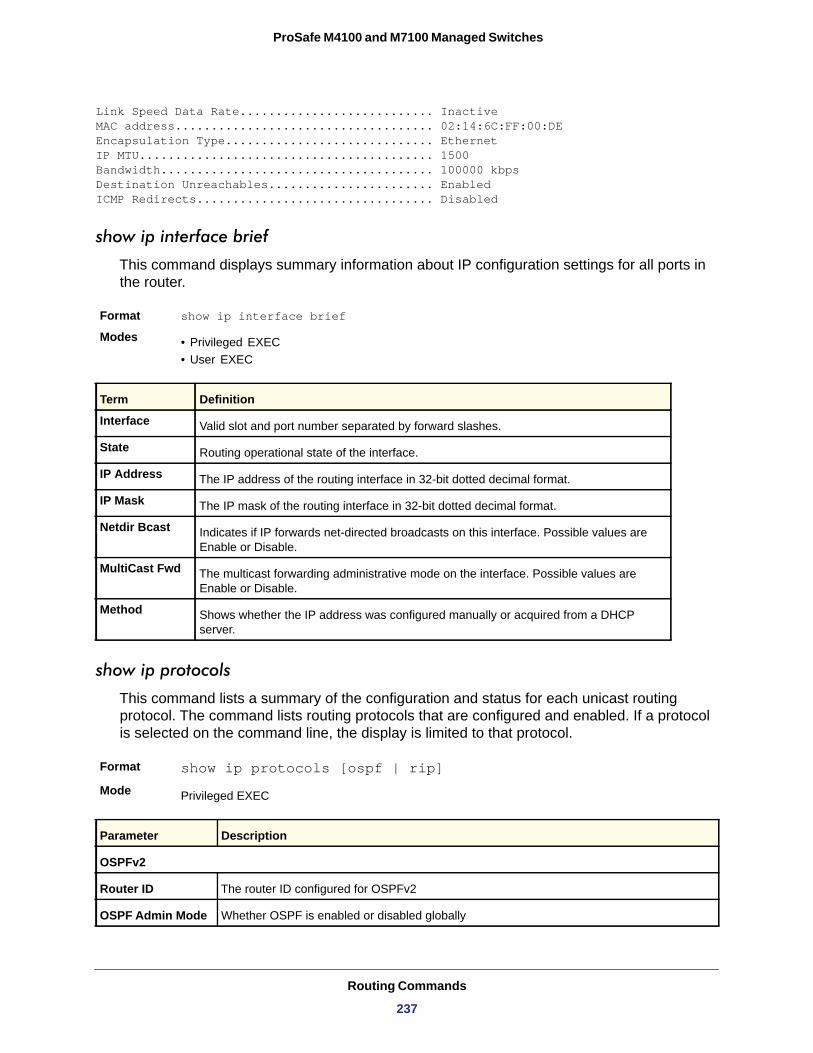
ProSafe M4100 and M7100 Managed Switches
Link Speed Data Rate........................... InactiveMAC address.................................... 02:14:6C:FF:00:DEEncapsulation Type............................. EthernetIP MTU......................................... 1500Bandwidth...................................... 100000 kbpsDestination Unreachables....................... EnabledICMP Redirects................................. Disabled
show ip interface brief
This command displays summary information about IP configuration settings for all ports in the router.
Format show ip interface brief
Modes • Privileged EXEC• User EXEC
Interface
State
IP Address
IP Mask
Netdir Bcast
MultiCast Fwd
Method
show ip protocols
This command lists a summary of the configuration and status for each unicast routing protocol. The command lists routing protocols that are configured and enabled. If a protocol is selected on the command line, the display is limited to that protocol.
Format show ip protocols [ospf | rip]
Mode
Term Definition
Valid slot and port number separated by forward slashes.
Routing operational state of the interface.
The IP address of the routing interface in 32-bit dotted decimal format.
The IP mask of the routing interface in 32-bit dotted decimal format.
Indicates if IP forwards net-directed broadcasts on this interface. Possible values are Enable or Disable.
The multicast forwarding administrative mode on the interface. Possible values are Enable or Disable.
Shows whether the IP address was configured manually or acquired from a DHCP server.
Privileged EXEC
Parameter Description
OSPFv2
Router ID The router ID configured for OSPFv2
OSPF Admin Mode Whether OSPF is enabled or disabled globally
Routing Commands
237
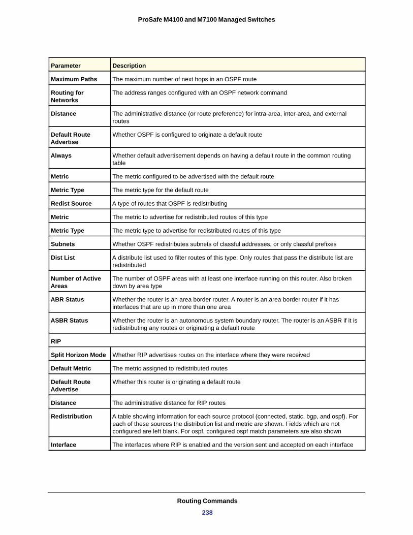
ProSafe M4100 and M7100 Managed Switches
Maximum Paths The maximum number of next hops in an OSPF route
Routing for Networks
The address ranges configured with an OSPF network command
Distance The administrative distance (or route preference) for intra-area, inter-area, and external routes
Default Route Advertise
Whether OSPF is configured to originate a default route
Always Whether default advertisement depends on having a default route in the common routing table
Metric The metric configured to be advertised with the default route
Metric Type The metric type for the default route
Redist Source A type of routes that OSPF is redistributing
Metric The metric to advertise for redistributed routes of this type
Metric Type The metric type to advertise for redistributed routes of this type
Subnets Whether OSPF redistributes subnets of classful addresses, or only classful prefixes
Dist List A distribute list used to filter routes of this type. Only routes that pass the distribute list are redistributed
Number of Active Areas
The number of OSPF areas with at least one interface running on this router. Also broken down by area type
ABR Status Whether the router is an area border router. A router is an area border router if it has interfaces that are up in more than one area
ASBR Status Whether the router is an autonomous system boundary router. The router is an ASBR if it is redistributing any routes or originating a default route
RIP
Split Horizon Mode Whether RIP advertises routes on the interface where they were received
Default Metric The metric assigned to redistributed routes
Default Route Advertise
Whether this router is originating a default route
Distance The administrative distance for RIP routes
Redistribution A table showing information for each source protocol (connected, static, bgp, and ospf). For each of these sources the distribution list and metric are shown. Fields which are not configured are left blank. For ospf, configured ospf match parameters are also shown
Interface The interfaces where RIP is enabled and the version sent and accepted on each interface
Parameter Description
Routing Commands
238
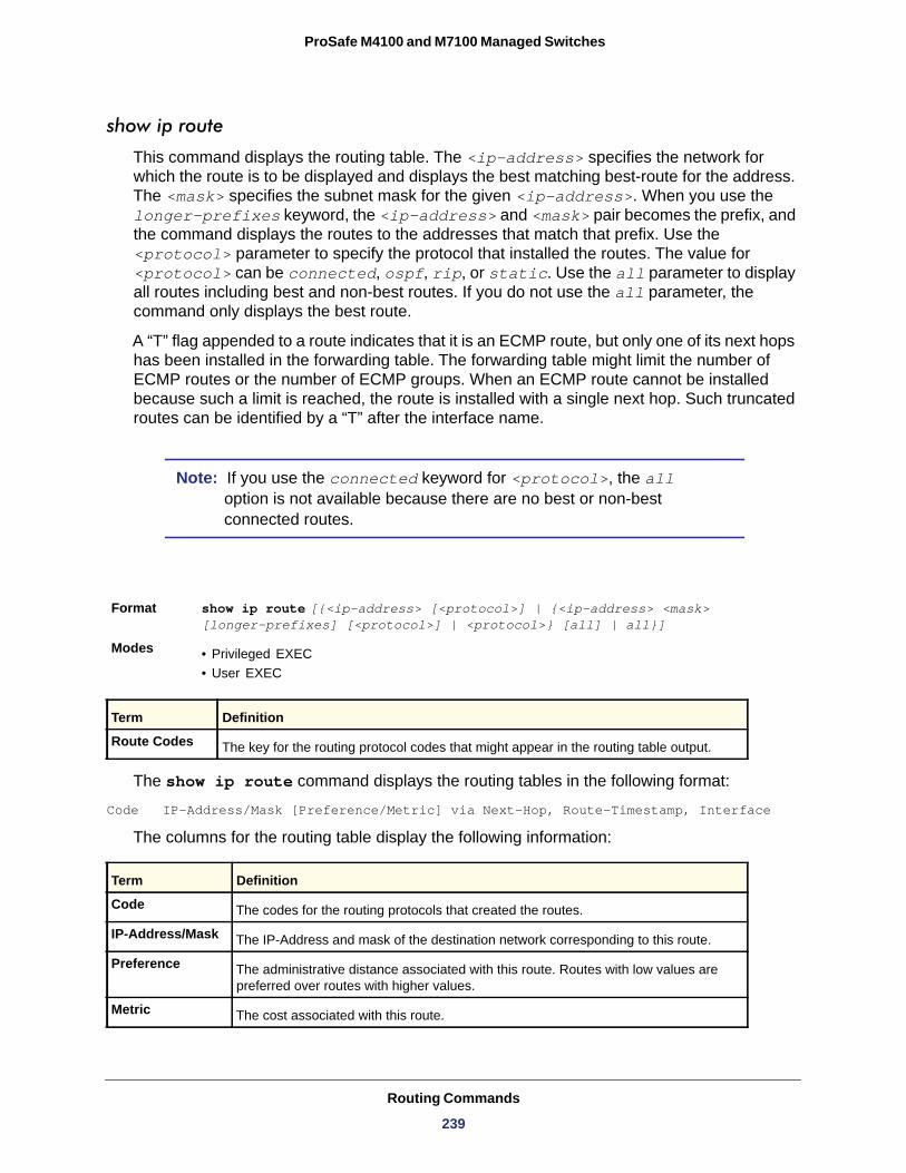
ProSafe M4100 and M7100 Managed Switches
show ip route
This command displays the routing table. The <ip-address> specifies the network for which the route is to be displayed and displays the best matching best-route for the address. The <mask> specifies the subnet mask for the given <ip-address>. When you use the longer-prefixes keyword, the <ip-address> and <mask> pair becomes the prefix, and the command displays the routes to the addresses that match that prefix. Use the <protocol> parameter to specify the protocol that installed the routes. The value for <protocol> can be connected, ospf, rip, or static. Use the all parameter to display all routes including best and non-best routes. If you do not use the all parameter, the command only displays the best route.
A “T” flag appended to a route indicates that it is an ECMP route, but only one of its next hops has been installed in the forwarding table. The forwarding table might limit the number of ECMP routes or the number of ECMP groups. When an ECMP route cannot be installed because such a limit is reached, the route is installed with a single next hop. Such truncated routes can be identified by a “T” after the interface name.
Note: If you use the connected keyword for <protocol>, the all option is not available because there are no best or non-best connected routes.
The show ip route command displays the routing tables in the following format:
Code IP-Address/Mask [Preference/Metric] via Next-Hop, Route-Timestamp, Interface
The columns for the routing table display the following information:
Format show ip route [{<ip-address> [<protocol>] | {<ip-address> <mask> [longer-prefixes] [<protocol>] | <protocol>} [all] | all}]
Modes • Privileged EXEC• User EXEC
Term Definition
Route Codes The key for the routing protocol codes that might appear in the routing table output.
Term Definition
Code The codes for the routing protocols that created the routes.
IP-Address/Mask The IP-Address and mask of the destination network corresponding to this route.
Preference The administrative distance associated with this route. Routes with low values are preferred over routes with higher values.
Metric The cost associated with this route.
Routing Commands
239
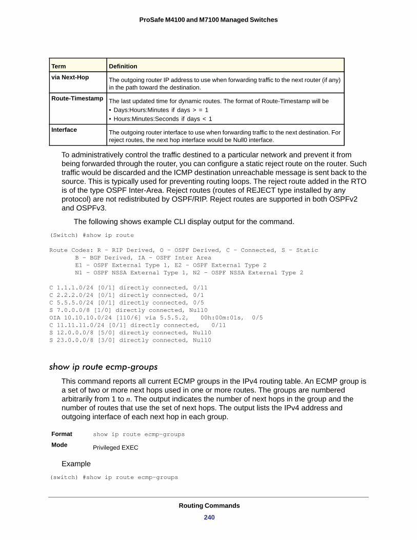
ProSafe M4100 and M7100 Managed Switches
To administratively control the traffic destined to a particular network and prevent it from being forwarded through the router, you can configure a static reject route on the router. Such traffic would be discarded and the ICMP destination unreachable message is sent back to the source. This is typically used for preventing routing loops. The reject route added in the RTO is of the type OSPF Inter-Area. Reject routes (routes of REJECT type installed by any protocol) are not redistributed by OSPF/RIP. Reject routes are supported in both OSPFv2 and OSPFv3.
The following shows example CLI display output for the command.
(Switch) #show ip route
Route Codes: R - RIP Derived, O - OSPF Derived, C - Connected, S - Static B - BGP Derived, IA - OSPF Inter Area E1 - OSPF External Type 1, E2 - OSPF External Type 2 N1 - OSPF NSSA External Type 1, N2 - OSPF NSSA External Type 2
C 1.1.1.0/24 [0/1] directly connected, 0/11C 2.2.2.0/24 [0/1] directly connected, 0/1C 5.5.5.0/24 [0/1] directly connected, 0/5S 7.0.0.0/8 [1/0] directly connected, Null0OIA 10.10.10.0/24 [110/6] via 5.5.5.2, 00h:00m:01s, 0/5C 11.11.11.0/24 [0/1] directly connected, 0/11S 12.0.0.0/8 [5/0] directly connected, Null0S 23.0.0.0/8 [3/0] directly connected, Null0
show ip route ecmp-groups
This command reports all current ECMP groups in the IPv4 routing table. An ECMP group is a set of two or more next hops used in one or more routes. The groups are numbered arbitrarily from 1 to n. The output indicates the number of next hops in the group and the number of routes that use the set of next hops. The output lists the IPv4 address and outgoing interface of each next hop in each group.
Format show ip route ecmp-groups
Mode
Example
(switch) #show ip route ecmp-groups
via Next-Hop The outgoing router IP address to use when forwarding traffic to the next router (if any) in the path toward the destination.
Route-Timestamp The last updated time for dynamic routes. The format of Route-Timestamp will be • Days:Hours:Minutes if days > = 1• Hours:Minutes:Seconds if days < 1
Interface The outgoing router interface to use when forwarding traffic to the next destination. For reject routes, the next hop interface would be Null0 interface.
Privileged EXEC
Term Definition
Routing Commands
240
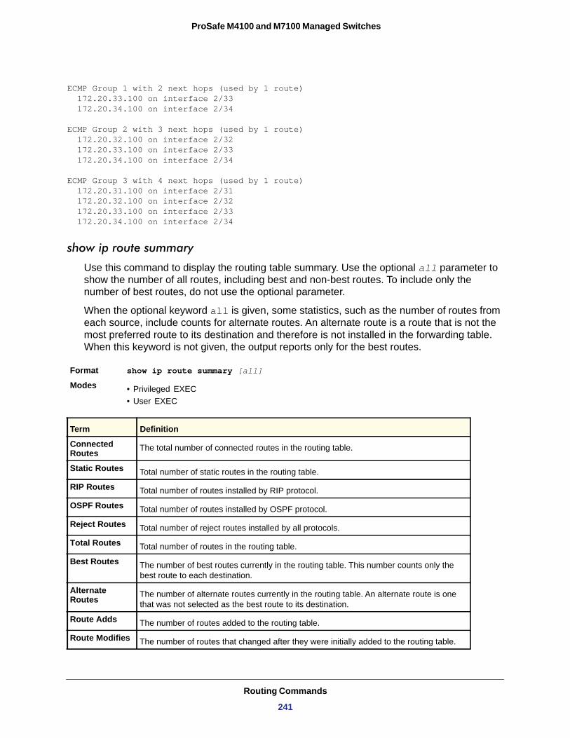
ProSafe M4100 and M7100 Managed Switches
ECMP Group 1 with 2 next hops (used by 1 route) 172.20.33.100 on interface 2/33 172.20.34.100 on interface 2/34
ECMP Group 2 with 3 next hops (used by 1 route) 172.20.32.100 on interface 2/32 172.20.33.100 on interface 2/33 172.20.34.100 on interface 2/34
ECMP Group 3 with 4 next hops (used by 1 route) 172.20.31.100 on interface 2/31 172.20.32.100 on interface 2/32 172.20.33.100 on interface 2/33 172.20.34.100 on interface 2/34
show ip route summary
Use this command to display the routing table summary. Use the optional all parameter to show the number of all routes, including best and non-best routes. To include only the number of best routes, do not use the optional parameter.
When the optional keyword all is given, some statistics, such as the number of routes from each source, include counts for alternate routes. An alternate route is a route that is not the most preferred route to its destination and therefore is not installed in the forwarding table. When this keyword is not given, the output reports only for the best routes.
Format show ip route summary [all]
Modes • Privileged EXEC• User EXEC
Term Definition
Connected Routes The total number of connected routes in the routing table.
Static Routes Total number of static routes in the routing table.
RIP Routes Total number of routes installed by RIP protocol.
OSPF Routes Total number of routes installed by OSPF protocol.
Reject Routes Total number of reject routes installed by all protocols.
Total Routes Total number of routes in the routing table.
Best Routes The number of best routes currently in the routing table. This number counts only the best route to each destination.
Alternate Routes The number of alternate routes currently in the routing table. An alternate route is one
that was not selected as the best route to its destination.
Route Adds The number of routes added to the routing table.
Route Modifies The number of routes that changed after they were initially added to the routing table.
Routing Commands
241
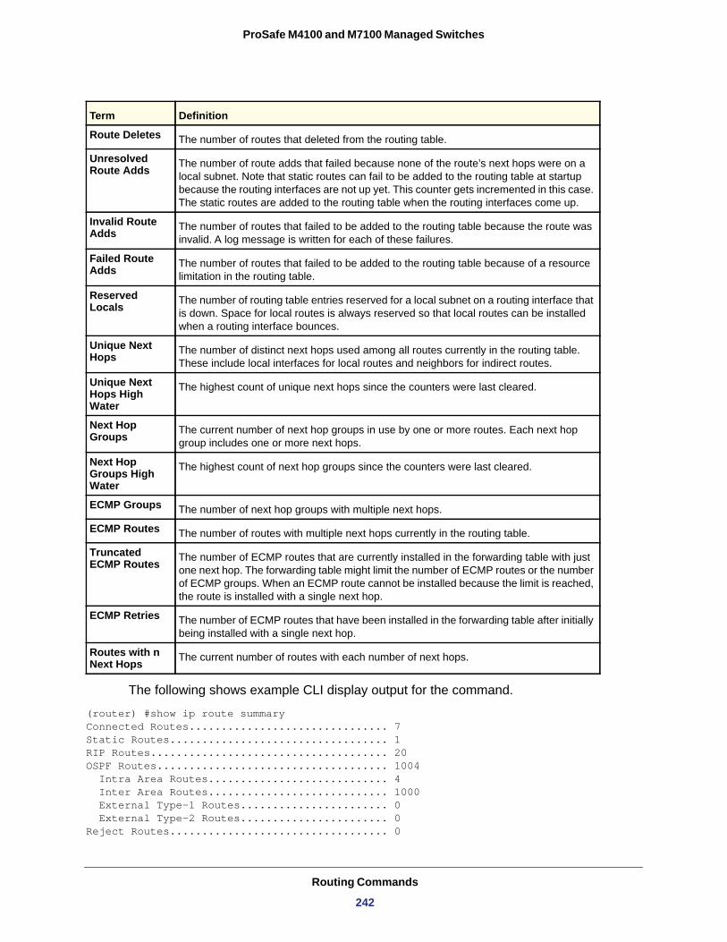
ProSafe M4100 and M7100 Managed Switches
The following shows example CLI display output for the command.
(router) #show ip route summaryConnected Routes............................... 7Static Routes.................................. 1RIP Routes..................................... 20OSPF Routes.................................... 1004 Intra Area Routes............................ 4 Inter Area Routes............................ 1000 External Type-1 Routes....................... 0 External Type-2 Routes....................... 0Reject Routes.................................. 0
Route Deletes The number of routes that deleted from the routing table.
Unresolved Route Adds The number of route adds that failed because none of the route’s next hops were on a
local subnet. Note that static routes can fail to be added to the routing table at startup because the routing interfaces are not up yet. This counter gets incremented in this case. The static routes are added to the routing table when the routing interfaces come up.
Invalid Route Adds The number of routes that failed to be added to the routing table because the route was
invalid. A log message is written for each of these failures.
Failed Route Adds The number of routes that failed to be added to the routing table because of a resource
limitation in the routing table.
Reserved Locals The number of routing table entries reserved for a local subnet on a routing interface that
is down. Space for local routes is always reserved so that local routes can be installed when a routing interface bounces.
Unique Next Hops The number of distinct next hops used among all routes currently in the routing table.
These include local interfaces for local routes and neighbors for indirect routes.
Unique Next Hops High Water
The highest count of unique next hops since the counters were last cleared.
Next Hop Groups The current number of next hop groups in use by one or more routes. Each next hop
group includes one or more next hops.
Next Hop Groups High Water
The highest count of next hop groups since the counters were last cleared.
ECMP Groups The number of next hop groups with multiple next hops.
ECMP Routes The number of routes with multiple next hops currently in the routing table.
Truncated ECMP Routes The number of ECMP routes that are currently installed in the forwarding table with just
one next hop. The forwarding table might limit the number of ECMP routes or the number of ECMP groups. When an ECMP route cannot be installed because the limit is reached, the route is installed with a single next hop.
ECMP Retries The number of ECMP routes that have been installed in the forwarding table after initially being installed with a single next hop.
Routes with n Next Hops The current number of routes with each number of next hops.
Term Definition
Routing Commands
242
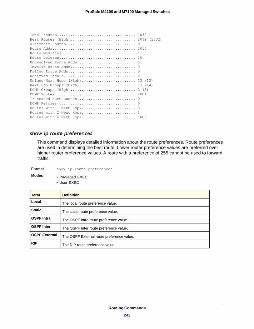
ProSafe M4100 and M7100 Managed Switches
Total routes................................... 1032Best Routes (High)............................. 1032 (1032)Alternate Routes............................... 0Route Adds..................................... 1010Route Modifies................................. 1Route Deletes.................................. 10Unresolved Route Adds.......................... 0Invalid Route Adds............................. 0Failed Route Adds.............................. 0Reserved Locals................................ 0Unique Next Hops (High)........................ 13 (13)Next Hop Groups (High)......................... 13 (14)ECMP Groups (High)............................. 2 (3)ECMP Routes.................................... 1001Truncated ECMP Routes.......................... 0ECMP Retries................................... 0Routes with 1 Next Hop......................... 31Routes with 2 Next Hops........................ 1Routes with 4 Next Hops........................ 1000
show ip route preferences
This command displays detailed information about the route preferences. Route preferences are used in determining the best route. Lower router preference values are preferred over higher router preference values. A route with a preference of 255 cannot be used to forward traffic.
Format show ip route preferences
Modes • Privileged EXEC• User EXEC
Local
Static
OSPF Intra
OSPF Inter
OSPF External
RIP
Term Definition
The local route preference value.
The static route preference value.
The OSPF Intra route preference value.
The OSPF Inter route preference value.
The OSPF External route preference value.
The RIP route preference value.
Routing Commands
243
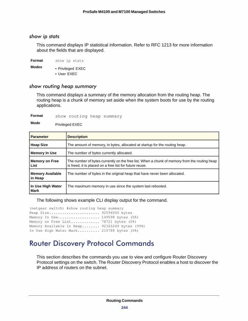
ProSafe M4100 and M7100 Managed Switches
show ip stats
This command displays IP statistical information. Refer to RFC 1213 for more information about the fields that are displayed.
Format show ip stats
Modes • Privileged EXEC• User EXEC
show routing heap summary
This command displays a summary of the memory allocation from the routing heap. The routing heap is a chunk of memory set aside when the system boots for use by the routing applications.
Format show routing heap summary
Mode
The following shows example CLI display output for the command.
(netgear switch) #show routing heap summary Heap Size....................... 92594000 bytes Memory In Use................... 149598 bytes (0%) Memory on Free List............. 78721 bytes (0%) Memory Available in Heap........ 92365249 bytes (99%) In Use High Water Mark.......... 210788 bytes (0%)
Router Discovery Protocol Commands
This section describes the commands you use to view and configure Router Discovery Protocol settings on the switch. The Router Discovery Protocol enables a host to discover the IP address of routers on the subnet.
Privileged EXEC
Parameter Description
Heap Size The amount of memory, in bytes, allocated at startup for the routing heap.
Memory In Use The number of bytes currently allocated.
Memory on Free List
The number of bytes currently on the free list. When a chunk of memory from the routing heap is freed, it is placed on a free list for future reuse.
Memory Available in Heap
The number of bytes in the original heap that have never been allocated.
In Use High Water Mark
The maximum memory in use since the system last rebooted.
Routing Commands
244
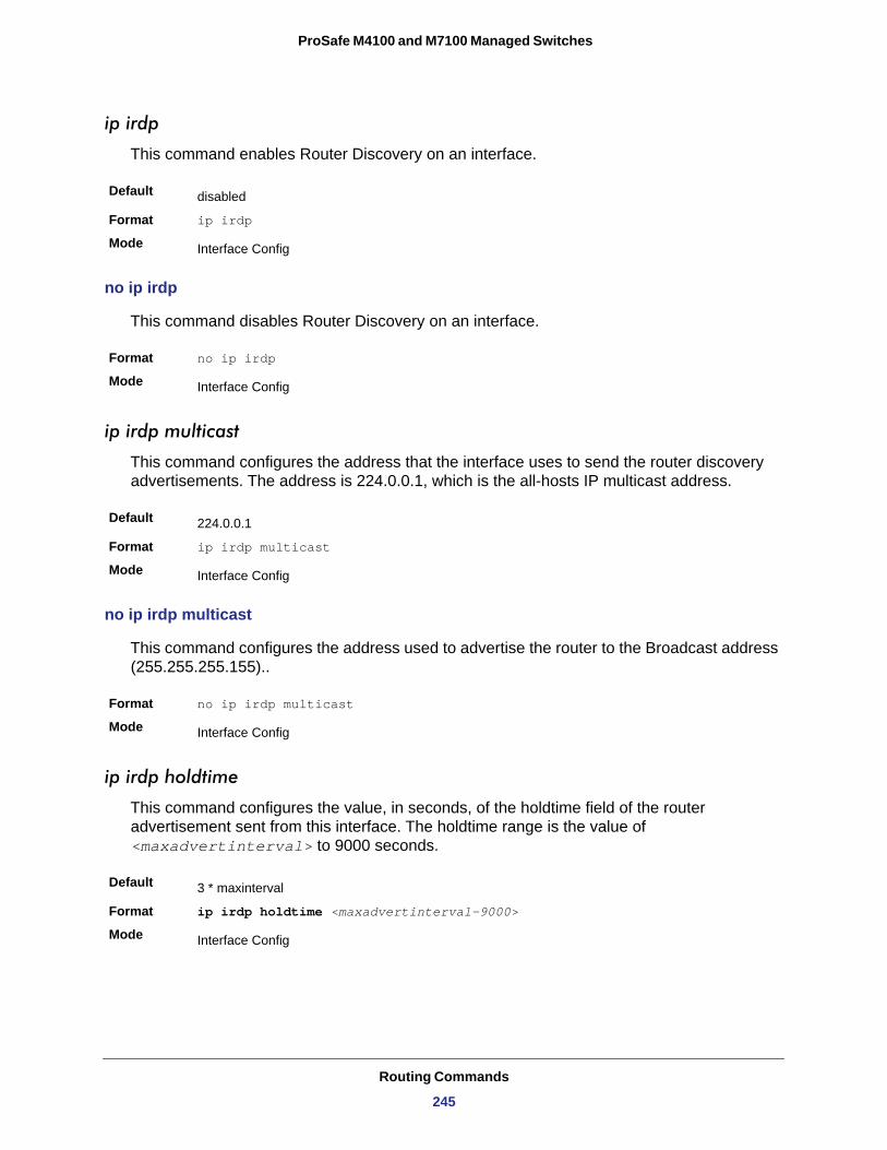
ProSafe M4100 and M7100 Managed Switches
ip irdp
This command enables Router Discovery on an interface.
Default
Format ip irdp
Mode
no ip irdp
This command disables Router Discovery on an interface.
Format no ip irdp
Mode
ip irdp multicast
This command configures the address that the interface uses to send the router discovery advertisements. The address is 224.0.0.1, which is the all-hosts IP multicast address.
Default
Format ip irdp multicast
Mode
no ip irdp multicast
This command configures the address used to advertise the router to the Broadcast address (255.255.255.155)..
Format no ip irdp multicast
Mode
ip irdp holdtime
This command configures the value, in seconds, of the holdtime field of the router advertisement sent from this interface. The holdtime range is the value of <maxadvertinterval> to 9000 seconds.
Default
Format ip irdp holdtime <maxadvertinterval-9000>
Mode
disabled
Interface Config
Interface Config
224.0.0.1
Interface Config
Interface Config
3 * maxinterval
Interface Config
Routing Commands
245
ProSafe M4100 and M7100 Managed Switches
no ip irdp holdtime
This command configures the default value, in seconds, of the holdtime field of the router advertisement sent from this interface.
Format no ip irdp holdtime
Mode
ip irdp maxadvertinterval
This command configures the maximum time, in seconds, allowed between sending router advertisements from the interface. The range for maxadvertinterval is 4–1800 seconds.
Default
Format ip irdp maxadvertinterval <4-1800>
Mode
no ip irdp maxadvertinterval
This command configures the default maximum time, in seconds.
Format no ip irdp maxadvertinterval
Mode
ip irdp minadvertinterval
This command configures the minimum time, in seconds, allowed between sending router advertisements from the interface. The range for minadvertinterval is three to the value of maxadvertinterval.
Default
Format ip irdp minadvertinterval <3-maxadvertinterval>
Mode
no ip irdp minadvertinterval
This command sets the default minimum time to the default.
Format no ip irdp minadvertinterval
Mode
Interface Config
600
Interface Config
Interface Config
0.75 * maxadvertinterval
Interface Config
Interface Config
Routing Commands
246
ProSafe M4100 and M7100 Managed Switches
ip irdp preference
This command configures the preferability of the address as a default router address, relative to other router addresses on the same subnet.
Default
Format ip irdp preference <-2147483648 to 2147483647>
Mode
no ip irdp preference
This command configures the default preferability of the address as a default router address, relative to other router addresses on the same subnet.
Format no ip irdp preference
Mode
show ip irdp
This command displays the router discovery information for all interfaces, or a specified interface.
Format show ip irdp {<slot/port> | all}
Modes • Privileged EXEC• User EXEC
Interface
Ad Mode
Advertise Address
Max Int
Min Int
Hold Time
Preference
0
Interface Config
Interface Config
Term Definition
The <slot/port> that matches the rest of the information in the row.
The advertise mode, which indicates whether router discovery is enabled or disabled on this interface.
The IP address to which the interface sends the advertisement.
The maximum advertise interval, which is the maximum time, in seconds, allowed between sending router advertisements from the interface.
The minimum advertise interval, which is the minimum time, in seconds, allowed between sending router advertisements from the interface.
The amount of time, in seconds, that a system should keep the router advertisement before discarding it.
The preference of the address as a default router address, relative to other router addresses on the same subnet.
Routing Commands
247
ProSafe M4100 and M7100 Managed Switches
Virtual LAN Routing Commands
This section describes the commands you use to view and configure VLAN routing and to view VLAN routing status information.
vlan routing
This command enables routing on a VLAN. The vlanid value has a range from 1 to 4093. The [interface ID] value has a range from 1 to 128. Typically, you will not supply the interface ID argument, and the system automatically selects the interface ID. However, if you specify an interface ID that is already in use, the CLI displays an error message and does not create the VLAN interface.
Format vlan routing <vlanid> [interface ID]
Mode
no vlan routing
This command deletes routing on a VLAN. The <vlanid> value has a range from 1 to 4093.
Format no vlan routing <vlanid>
Mode
show ip vlan
This command displays the VLAN routing information for all VLANs with routing enabled.
Format show ip vlan
Modes • Privileged EXEC• User EXEC
MAC Address used by Routing VLANs
VLAN ID
Logical Interface
IP Address
Subnet Mask
VLAN Config
VLAN Config
Term Definition
The MAC Address associated with the internal bridge-router interface (IBRI). The same MAC Address is used by all VLAN routing interfaces. It will be displayed above the per-VLAN information.
The identifier of the VLAN.
The logical slot/port associated with the VLAN routing interface.
The IP address associated with this VLAN.
The subnet mask that is associated with this VLAN.
Routing Commands
248
ProSafe M4100 and M7100 Managed Switches
Virtual Router Redundancy Protocol Commands
This section describes the commands you use to view and configure Virtual Router Redundancy Protocol (VRRP) and to view VRRP status information. VRRP helps provide failover and load balancing when you configure two devices as a VRRP pair.
ip vrrp (Global Config)
Use this command in Global Config mode to enable the administrative mode of VRRP on the router.
Default
Format ip vrrp
Mode
no ip vrrp
Use this command in Global Config mode to diable the default administrative mode of VRRP on the router.
Format no ip vrrp
Mode
ip vrrp (Interface Config)
Use this command in Interface Config mode to create a virtual router associated with the interface. The parameter <vrid> is the virtual router ID, which has an integer value range from 1 to 255.
Format ip vrrp <vrid>
Mode
no ip vrrp
Use this command in Interface Config mode to delete the virtual router associated with the interface. The virtual Router ID, <vrid>, is an integer value that ranges from 1 to 255.
Format no ip vrrp <vrid>
Mode
none
Global Config
Global Config
Interface Config
Interface Config
Routing Commands
249
ProSafe M4100 and M7100 Managed Switches
ip vrrp mode
This command enables the virtual router configured on the specified interface. Enabling the status field starts a virtual router. The parameter <vrid> is the virtual router ID which has an integer value ranging from 1 to 255.
Default
Format ip vrrp <vrid> mode
Mode
no ip vrrp mode
This command disables the virtual router configured on the specified interface. Disabling the status field stops a virtual router.
Format no ip vrrp <vrid> mode
Mode
ip vrrp ip
This command sets the virtual router IP address value for an interface. The value for <ipaddr> is the IP address which is to be configured on that interface for VRRP. The parameter <vrid> is the virtual router ID which has an integer value range from 1 to 255. You can use the optional [secondary] parameter to designate the IP address as a secondary IP address.
Default
Format ip vrrp <vrid> ip <ipaddr> [secondary]
Mode
no ip vrrp ip
Use this command in Interface Config mode to delete a secondary IP address value from the interface. To delete the primary IP address, you must delete the virtual router on the interface.
Format no ip vrrp <vrid> <ipaddress> secondary
Mode
ip vrrp authentication
This command sets the authorization details value for the virtual router configured on a specified interface, The parameter {none | simple} specifies the authoritization type for virtual router configured on the specified interface. The parameter {key} is optional, it is only
disabled
Interface Config
Interface Config
none
Interface Config
Interface Config
Routing Commands
250
ProSafe M4100 and M7100 Managed Switches
required when authorization type is simple text apssword. The parameter <vrid> is the virtual router IFD which has an integer value range from 1 to 255.
Default
Format ip vrrp <vrid> authentication {none | simple <key>}
Mode
no ip vrrp authentication
This command sets the default authorization details value for the virtual router configured on a specified interface.
Format no ip vrrp <vrid> authentication
Mode
ip vrrp preempt
This command sets the preemption mode value for the virtual router configured on a specified interface. The parameter <vrid> is the virtual router ID, which is an integer from 1 to 255.
Default
Format ip vrrp <vrid> preempt
Mode
no ip vrrp preempt
This command sets the default preemption mode value for the virtual router configured on a specified interface.
Format no ip vrrp <vrid> preempt
Mode
ip vrrp priority
This command sets the priority of a router within a VRRP group. Higher values equal higher priority. The range is from 1 to 254. The parameter <vrid> is the virtual router ID, whose range is from 1 to 255.
The router with the highest priority is elected master. If a router is configured with the address used as the address of the virtual router, the router is called the “address owner.” The priority of the address owner is always 255 so that the address owner is always master. If the master has a priority less than 255 (it is not the address owner) and you configure the priority of
no authorization
Interface Config
Interface Config
enabled
Interface Config
Interface Config
Routing Commands
251
ProSafe M4100 and M7100 Managed Switches
another router in the group higher than the master’s priority, the router will take over as master only if preempt mode is enabled.
Default
Format ip vrrp <vrid> priority <1-254>
Mode
no ip vrrp priority
This command sets the default priority value for the virtual router configured on a specified interface.
Format no ip vrrp <vrid> priority
Mode
ip vrrp timers advertise
This command sets the frequency, in seconds, that an interface on the specified virtual router sends a virtual router advertisement.
Default
Format ip vrrp <vrid> timers advertise <1-255>
Mode
no ip vrrp timers advertise
This command sets the default virtual router advertisement value for an interface.
Format no ip vrrp <vrid> timers advertise
Mode
ip vrrp track interface
Use this command to alter the priority of the VRRP router based on the availability of its interfaces. This command is useful for tracking interfaces that are not configured for VRRP. Only IP interfaces are tracked. A tracked interface is up if the IP on that interface is up. Otherwise, the tracked interface is down.
When the tracked interface is down or the interface has been removed from the router, the priority of the VRRP router will be decremented by the value specified in the <priority> argument. When the interface is up for IP protocol, the priority will be incremented by the <priority> value.
A VRRP configured interface can track more than one interface. When a tracked interface goes down, then the priority of the router will be decreased by 10 (the default priority
100 unless the router is the address owner, in which case its priority is automatically set to 255.
Interface Config
Interface Config
1
Interface Config
Interface Config
Routing Commands
252
ProSafe M4100 and M7100 Managed Switches
decrement) for each downed interface. The default priority decrement is changed using the <priority> argument. The default priority of the virtual router is 100, and the default decrement priority is 10. By default, no interface are tracked. If you specify just the interface to be tracked, without giving the optional priority, the default priority will be set. The default priority decrement is 10.
Default
Format ip vrrp <vrid> track interface <slot/port> [decrement <priority>]
Mode
no ip vrrp track interface
Use this command to remove the interface from the tracked list or to restore the priority decrement to its default.
Format no ip vrrp <vrid> track interface <slot/port> [decrement]
Mode
ip vrrp track ip route
Use this command to track the route reachability. When the tracked route is deleted, the priority of the VRRP router will be decremented by the value specified in the <priority> argument. When the tracked route is added, the priority will be incremented by the same.
A VRRP configured interface can track more than one route. When a tracked route goes down, then the priority of the router will be decreased by 10 (the default priority decrement) for each downed route. By default no routes are tracked. If you specify just the route to be tracked, without giving the optional priority, the default priority will be set. The default priority decrement is 10. The default priority decrement is changed using the <priority> argument.
Default
Format ip vrrp <vrid> track ip route <ip-address/prefix-length> [decrement <priority>]
Mode
no ip vrrp track ip route
Use this command to remove the route from the tracked list or to restore the priority decrement to its default. When removing a tracked IP route from the tracked list, the priority should be incremented by the decrement value if the route is not reachable.
Format no ip vrrp <vrid> track ip route <ip-address/prefix-length> [decrement]
Mode
priority: 10
Interface Config
Interface Config
priority: 10
Interface Config
Interface Config
Routing Commands
253
ProSafe M4100 and M7100 Managed Switches
ip vrrp <vrid> accept-mode
This command is used to allow a router to respond to ICMP Echo Requests sent to an address on a VRRP virtual router. VRRP supports responding to pings, but does not allow the VRRP Master to accept other types of packets. A new configuration option controls whether the router responds to Echo Requests sent to a VRRP IP address.
The VRRP Master responds to both fragmented and unfragmented ICMP Echo Request packets. The VRRP Master responds to Echo Requests sent to the virtual router's primary address or any of its secondary addresses.
Ping to a VRRP IP address only works from the host side (where the VRRP router is configured). There is no value in pinging to the VRRP IP from another interface because packet flow from the network to the host does not involve VRRP. This is used only to troubleshoot a connectivity problem for traffic originating on the VRRP protected LAN.
Members of the virtual router who are in backup state discard ping packets destined to VRRP address(es), just as they discard any Ethernet frame sent to a VRRP MAC address. When the VRRP master responds with an Echo Reply, the source IPv4 address is the VRRP address and source MAC address is the virtual router's MAC address.
There is a separate command "ip icmp echo-reply" that controls whether the router responds to ICMP Echo Requests. When Echo Replies are disabled using that command, the VRRP master does not respond to Echo Requests, even if this new option is enabled.
Default
Format ip vrrp <vrid> accept-mode
Mode
no ip vrrp vrid accept-mode
This command is used to allow a router to respond to ICMP Echo Requests sent to an address on a VRRP virtual router.
Format no ip vrrp <vrid> accept-mode
Mode
show ip vrrp interface stats
This command displays the statistical information about each virtual router configured on the switch.
Format show ip vrrp interface stats <slot/port> <vrid>
Modes • Privileged EXEC• User EXEC
disabled
Interface Config
Interface Config
Routing Commands
254
ProSafe M4100 and M7100 Managed Switches
Uptime
Protocol
State Transitioned to Master
Advertisement Received
Advertisement Interval Errors
Authentication Failure
IP TTL errors
Zero Priority Packets Received
Zero Priority Packets Sent
Invalid Type Packets Received
Address List Errors
Invalid Authentication Type
Authentication Type Mismatch
Packet Length Errors
show ip vrrp
This command displays whether VRRP functionality is enabled or disabled on the switch. It also displays some global parameters which are required for monitoring. This command takes no options.
Format show ip vrrp
Modes • Privileged EXEC• User EXEC
Term Definition
The time that the virtual router has been up, in days, hours, minutes, and seconds.
The protocol configured on the interface.
The total number of times virtual router states has changed to MASTER.
The total number of VRRP advertisements received by this virtual router.
The total number of VRRP advertisements received for which advertisement interval is different than the configured value for this virtual router.
The total number of VRRP packets received that do not pass the authentication check.
The total number of VRRP packets received by the virtual router with IP TTL (time to live) not equal to 255.
The total number of VRRP packets received by virtual router with a priority of '0'.
The total number of VRRP packets sent by the virtual router with a priority of '0'.
The total number of VRRP packets received by the virtual router with invalid 'type' field.
The total number of VRRP packets received for which address list does not match the locally configured list for the virtual router.
The total number of VRRP packets received with unknown authentication type.
The total number of VRRP advertisements received for which 'auth type' not equal to locally configured one for this virtual router.
The total number of VRRP packets received with packet length less than length of VRRP header.
Routing Commands
255
ProSafe M4100 and M7100 Managed Switches
Admin Mode
Router Checksum Errors
Router Version Errors
Router VRID Errors
show ip vrrp interface
This command displays all configuration information and VRRP router statistics of a virtual router configured on a specific interface. Use the output of the command to verify the track interface and track IP route configurations.
Format show ip vrrp interface {<interface-name> <vrid> }
Modes • Privileged EXEC• User EXEC
Primary IP Address
VMAC address
Authentication type
Priority
Configured Priority
Advertisement interval
Pre-Empt Mode
Administrative Mode
State
The following shows example CLI display output for the command.
(Switch)#show ip vrrp interface 0/1 1
Primary IP Address............................. 1.1.1.5VMAC Address................................... 00:00:5e:00:01:01Authentication Type............................ NonePriority....................................... 100 Configured priority.......................... 100
Term Definition
The administrative mode for VRRP functionality on the switch.
The total number of VRRP packets received with an invalid VRRP checksum value.
The total number of VRRP packets received with Unknown or unsupported version number.
The total number of VRRP packets received with invalid VRID for this virtual router.
Term Definition
The configured IP address for the Virtual router.
The VMAC address of the specified router.
The authentication type for the specific virtual router.
The priority value for the specific virtual router, taking into account any priority decrements for tracked interfaces or routes.
The priority configured through the ip vrrp <vrid> priority <1-254> command.
The advertisement interval in seconds for the specific virtual router.
The preemption mode configured on the specified virtual router.
The status (Enable or Disable) of the specific router.
The state (Master/backup) of the virtual router.
Routing Commands
256
ProSafe M4100 and M7100 Managed Switches
Advertisement Interval (secs).................. 1Pre-empt Mode.................................. EnableAdministrative Mode............................ DisableAccept Mode.................................... EnableState.......................................... InitializedTrack Interface State DecrementPriority--------------- ------ ------------------<0/1> down 10 TrackRoute (pfx/len) StateDecrementPriority------------------------ ------ ------------------10.10.10.1/255.255.255.0 down 10
show ip vrrp interface
This command displays information about each virtual router configured on the switch. This command takes no options. It displays information about each virtual router.
Format show ip vrrp interface brief
Modes • Privileged EXEC• User EXEC
Interface
VRID
IP Address
Mode
State
DHCP and BOOTP Relay Commands
This section describes the commands you use to configure BootP/DHCP Relay on the switch. A DHCP relay agent operates at Layer 3 and forwards DHCP requests and replies between clients and servers when they are not on the same physical subnet.
bootpdhcprelay cidoptmode
This command enables the circuit ID option mode for BootP/DHCP Relay on the system.
Default
Format bootpdhcprelay cidoptmode
Mode
Term Definition
Valid slot and port number separated by forward slashes.
The router ID of the virtual router.
The virtual router IP address.
Indicates whether the virtual router is enabled or disabled.
The state (Master/backup) of the virtual router.
disabled
Global Config
Routing Commands
257
ProSafe M4100 and M7100 Managed Switches
no bootpdhcprelay cidoptmode
This command disables the circuit ID option mode for BootP/DHCP Relay on the system.
Format no bootpdhcprelay cidoptmode
Mode
bootpdhcprelay maxhopcount
This command configures the maximum allowable relay agent hops for BootP/DHCP Relay on the system. The <hops> parameter has a range of 1–16.
Default
Format bootpdhcprelay maxhopcount <1-16>
Mode
no bootpdhcprelay maxhopcount
This command configures the default maximum allowable relay agent hops for BootP/DHCP Relay on the system.
Format no bootpdhcprelay maxhopcount
Mode
bootpdhcprelay minwaittime
This command configures the minimum wait time in seconds for BootP/DHCP Relay on the system. When the BOOTP relay agent receives a BOOTREQUEST message, it MAY use the seconds-since-client-began-booting field of the request as a factor in deciding whether to relay the request or not. The parameter has a range of 0–100 seconds.
Default
Format bootpdhcprelay minwaittime <0-100>
Mode
no bootpdhcprelay minwaittime
This command configures the default minimum wait time in seconds for BootP/DHCP Relay on the system.
Format no bootpdhcprelay minwaittime
Mode
Global Config
4
Global Config
Global Config
0
Global Config
Global Config
Routing Commands
258
ProSafe M4100 and M7100 Managed Switches
show bootpdhcprelay
This command displays the BootP/DHCP Relay information.
Format show bootpdhcprelay
Modes • Privileged EXEC• User EXEC
IP Helper Commands
This section describes the commands to configure a DHCP relay agent with multiple DHCP server addresses per routing interface, and to use different server addresses for client packets arriving on different interfaces on the relay agent.
clear ip helper statistics
Use this command to reset the statistics displayed in the show ip helper statistics command to zero.
Format clear ip helper statistics
Mode
ip helper-address (Global Config)
Use the Global Configuration ip helper-address command to have the switch forward User Datagram Protocol (UDP) broadcasts received on an interface. To disable the forwarding of broadcast packets to specific addresses, use the no form of this command.
Term Definition
Maximum Hop Count The maximum allowable relay agent hops.
Minimum Wait Time (Seconds) The minimum wait time.
Admin Mode Indicates whether relaying of requests is enabled or disabled.
Server IP Address The IP address for the BootP/DHCP Relay server.
Circuit Id Option Mode The DHCP circuit Id option which might be enabled or disabled.
Requests Received The number or requests received.
Requests Relayed The number of requests relayed.
Packets Discarded The number of packets discarded.
Privileged EXEC
Routing Commands
259
ProSafe M4100 and M7100 Managed Switches
The ip helper-address command forwards specific UDP broadcast from one interface to another. You can define many helper addresses but the total number of address-port pairs is limited to 128 for the whole device. The setting of a helper address for a specific interface has precedence over a setting of a helper address for all interfaces.
Ip-address: Destination broadcast or host address to be used when forwarding UDP broadcasts. You can specify 0.0.0.0 to indicate not to forward the UDP packet to any host and use "255.255.255.255" to broadcast the UDP packets to all hosts on the target subnet.
udp-port-list: The broadcast packet destination UDP port number to forward. If not specified, packets for the default services are forwarded to the helper address. Valid range, 0-65535.
Default
Format ip helper-address <ip-address> {<1-65535>|dhcp|domain|isakmp|mobile-ip|nameserver|netbios-dgm|netbios-ns|ntp|pim-auto-rip|rip|tacacs|tftp|time}
Mode
no ip helper-address (Global Config)
Use this command to remove the IP address from the previously configured list. The no command without an <ip-address> argument removes the entire list of helper addresses on that interface.
Format no ip helper-address {<ip-address>} {<1-65535>|dhcp|domain|isakmp|mobile-ip|nameserver|netbios-dgm|netbios-ns|ntp|pim-auto-rip|rip|tacacs|tftp|time}
Mode
ip helper enable
Use this command to enable relay of UDP packets. This command can be used to temporarily disable IP helper without deleting all IP helper addresses. This command replaces the bootpdhcprelay enable command, but affects not only relay of DHCP packets, but also relay of any other protocols for which an IP helper address has been configured.
Default
Format ip helper enable
Mode
no ip helper enable
Use this command to disable relay of all UDP packets.
Format no ip helper enable
Mode
Disabled
Global Config
GlobalConfig
disabled
Global Config
Global Config
Routing Commands
260
ProSafe M4100 and M7100 Managed Switches
ip helper-address
Use this command to add a unicast helper address to the list of helper addresses on an interface. This is the address of a DHCP server. This command can be applied multiple times on the routing interface to form the helper addresses list until the list reaches the maximum supported helper addresses.
Format ip helper-address <ip-address> {<1-65535>|dhcp|domain|isakmp|mobile-ip|nameserver|netbios-dgm|netbios-ns|ntp|pim-auto-rip|rip|tacacs|tftp|time}
Mode
no ip helper-address
Use this command to remove the IP address from the previously configured list. The no command without an <ip-address> argument removes the entire list of helper addresses on that interface.
Format no ip helper-address {<ip-address>}{<1-65535>|dhcp|domain|isakmp|mobile-ip|nameserver|netbios-dgm|netbios-ns|ntp|pim-auto-rip|rip|tacacs|tftp|time}
Mode
ip helper-address discard
Use this command to drop matching packets.
Format ip helper-address discard {<1-65535>|dhcp|domain|isakmp|mobile-ip|nameserver|netbios-dgm|netbios-ns|ntp|pim-auto-rip|rip|tacacs|tftp|time}
Mode
no ip helper-address discard
Use this command to permit the matching packets.
Format no ip helper-address discard{<1-65535>|dhcp|domain|isakmp|mobile-ip|nameserver|netbios-dgm|netbios-ns|ntp|pim-auto-rip|rip|tacacs|tftp|time}
Mode
show ip helper-address
Use this command to display the configured helper addresses on the given interface.
Format show ip helper-address <interface>
Mode • Privileged EXEC• User EXEC
Interface Config
Interface Config
Interface Config
Interface Config
Routing Commands
261
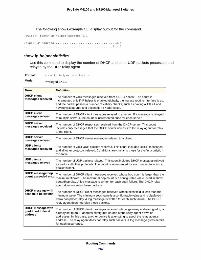
ProSafe M4100 and M7100 Managed Switches
The following shows example CLI display output for the command.
(switch) #show ip helper-address 0/1
Helper IP Address.............................. 1.2.3.4............................................... 1.2.3.5
show ip helper statistics
Use this command to display the number of DHCP and other UDP packets processed and relayed by the UDP relay agent.
Format show ip helper statistics
Mode Privileged EXEC
Term Definition
DHCP client messages received The number of valid messages received from a DHCP client. The count is
incremented only if IP helper is enabled globally, the ingress routing interface is up, and the packet passes a number of validity checks, such as having a TTL>1 and having valid source and destination IP addresses.
DHCP client messages relayed The number of DHCP client messages relayed to a server. If a message is relayed
to multiple servers, the count is incremented once for each server.
DHCP server messages received The number of DHCP responses received from the DHCP server. This count
includes only messages that the DHCP server unicasts to the relay agent for relay to the client.
DHCP server messages relayed The number of DHCP server messages relayed to a client.
UDP clients messages received The number of valid UDP packets received. This count includes DHCP messages
and all other protocols relayed. Conditions are similar to those for the first statistic in this table.
UDP clients messages relayed The number of UDP packets relayed. This count includes DHCP messages relayed
as well as all other protocols. The count is incremented for each server to which a packet is sent.
DHCP message hop count exceeded max The number of DHCP client messages received whose hop count is larger than the
maximum allowed. The maximum hop count is a configurable value listed in show bootpdhcprelay. A log message is written for each such failure. The DHCP relay agent does not relay these packets.
DHCP message with secs field below min The number of DHCP client messages received whose secs field is less than the
minimum value. The minimum secs value is a configurable value and is displayed in show bootpdhcprelay. A log message is written for each such failure. The DHCP relay agent does not relay these packets.
DHCP message with giaddr set to local address
The number of DHCP client messages received whose gateway address, giaddr, is already set to an IP address configured on one of the relay agent’s own IP addresses. In this case, another device is attempting to spoof the relay agent’s address. The relay agent does not relay such packets. A log message gives details for each occurrence.
Routing Commands
262
ProSafe M4100 and M7100 Managed Switches
Open Shortest Path First (OSPF) Commands
This section describes the commands you use to view and configure OSPF, which is a link-state routing protocol that you use to route traffic within a network.
router ospf
Use this command to enter Router OSPF mode.
Format router ospf
Mode
enable (OSPF)
This command resets the default administrative mode of OSPF in the router (active).
Default
Format enable
Mode
no enable (OSPF)
This command sets the administrative mode of OSPF in the router to inactive.
Format no enable
Mode
network area (OSPF)
Use this command to enable OSPFv2 on an interface and set its area ID if the IP address of an interface is covered by this network command.
Default
Format network <ip-address> <wildcard-mask> area <area-id>
Mode
Packets with expired TTL The number of packets received with TTL of 0 or 1 that might otherwise have been
relayed.
Packets that matched a discard entry
The number of packets ignored by the relay agent because they match a discard relay entry.
Global Config
enabled
Router OSPF Config
Router OSPF Config
disabled
Router OSPF Config
Term Definition
Routing Commands
263
ProSafe M4100 and M7100 Managed Switches
no network area (OSPF)
Use this command to disable the OSPFv2 on an interface if the IP address of an interface was earlier covered by this network command.
Format no network <ip-address> <wildcard-mask> area <area-id>
Mode
ip ospf area
Use this command to enable OSPFv2 and set the area ID of an interface. The <area-id> is an IP address formatted as a 4-digit dotted-decimal number or a decimal value in the range of <0-4294967295>. This command supersedes the effects of the network area command. It can also be used to configure the advertiseability of the secondary addresses on this interface into the OSPFv2 domain.
Default
Format ip ospf area <area-id> [secondaries none]
Mode
no ip ospf area
Use this command to disable OSPF on an interface.
Format no ip ospf area [secondaries none]
Mode
1583compatibility
This command enables OSPF 1583 compatibility.
Note: 1583 compatibility mode is enabled by default. If all OSPF routers in the routing domain are capable of operating according to RFC 2328, OSPF 1583 compatibility mode should be disabled.
Default
Format 1583compatibility
Mode
Router OSPF Config
disabled
Interface Config
Interface Config
enabled
Router OSPF Config
Routing Commands
264
ProSafe M4100 and M7100 Managed Switches
no 1583compatibility
This command disables OSPF 1583 compatibility.
Format no 1583compatibility
Mode
area default-cost (OSPF)
This command configures the default cost for the stub area. You must specify the area ID and an integer value between 1-16,777,215.
Format area <areaid> default-cost <1-16777215>
Mode
area nssa (OSPF)
This command configures the specified area id to function as an NSSA.
Format area <areaid> nssa
Mode
no area nssa
This command disables nsa from the specified area id.
Format no area <areaid> nssa
Mode
area nssa default-info-originate (OSPF)
This command configures the metric value and type for the default route advertised into the NSSA. The optional metric parameter specifies the metric of the default route and is to be in a range of 1-16777214. If no metric is specified, the default value is 10. The metric type can be comparable (nssa-external 1) or non-comparable (nssa-external 2)
Format area <areaid> nssa default-info-originate [<metric>] [{comparable | non-comparable}]
Mode
Router OSPF Config
Router OSPF Config
Router OSPF Config
Router OSPF Config
Router OSPF Config
Routing Commands
265
ProSafe M4100 and M7100 Managed Switches
no area nssa default-info-originate (OSPF)
This command disables the default route advertised into the NSSA.
Format no area <areaid> nssa default-info-originate [<metric>] [{comparable | non-comparable}]
Mode
area nssa no-redistribute (OSPF)
This command configures the NSSA Area Border router (ABR) so that learned external routes will not be redistributed to the NSSA.
Format area <areaid> nssa no-redistribute
Mode
no area nssa no-redistribute (OSPF)
This command disables the NSSA ABR so that learned external routes are redistributed to the NSSA.
Format no area <areaid> nssa no-redistribute
Mode
area nssa no-summary (OSPF)
This command configures the NSSA so that the summary LSAs are not advertised into the NSSA.
Format area <areaid> nssa no-summary
Mode
no area nssa no-summary (OSPF)
This command disables nssa from the summary LSAs.
Format no area <areaid> nssa no-summary
Mode
area nssa translator-role (OSPF)
This command configures the translator role of the NSSA. A value of always causes the router to assume the role of the translator the instant it becomes a border router and a value
Router OSPF Config
Router OSPF Config
Router OSPF Config
Router OSPF Config
Router OSPF Config
Routing Commands
266
ProSafe M4100 and M7100 Managed Switches
of candidate causes the router to participate in the translator election process when it attains a border router status.
Format area <areaid> nssa translator-role {always | candidate}
Mode
no area nssa translator (OSPF)
This command disables the nssa translator role from the specified area id.
Format no area <areaid> nssa translator-role {always | candidate}
Mode
area nssa translator-stab-intv (OSPF)
This command configures the translator <stabilityinterval> of the NSSA. The <stabilityinterval> is the period of time that an elected translator continues to perform its duties after it determines that its translator status has been deposed by another router.
Format area <areaid> nssa translator-stab-intv <stabilityinterval>
Mode
no area nssa translator-stab-intv (OSPF)
This command disables the nssa translator’s <stabilityinterval> from the specified area id.
Format no area <areaid> nssa translator-stab-intv <stabilityinterval>
Mode
area range (OSPF)
Use this command in Router Configuration mode to configure a summary prefix that an area border router advertises for a specific area.
Default
Format area areaid range prefix netmask {summarylink | nssaexternallink} [advertise | not-advertise] [cost cost]
Mode
Router OSPF Config
Router OSPF Config
Router OSPF Config
Router OSPF Config
No area ranges are configured by default. No cost is configured by default.
OSPFv2 Router Configuration
Routing Commands
267
ProSafe M4100 and M7100 Managed Switches
no area range
The no form of this command deletes a specified area range or reverts an option to its default.
Format no area areaid range prefix netmask {summarylink | nssaexternallink} [advertise | not-advertise] [cost]
Mode
area stub (OSPF)
This command creates a stub area for the specified area ID. A stub area is characterized by the fact that AS External LSAs are not propagated into the area. Removing AS External LSAs and Summary LSAs can significantly reduce the link state database of routers within the stub area.
Format area <areaid> stub
Mode
Parameter Description
area-id The area identifier for the area whose networks are to be summarized.
prefix netmask The summary prefix to be advertised when the ABR computes a route to one or more networks within this prefix in this area.
summarylink When this keyword is given, the area range is used when summarizing prefixes advertised in type 3 summary LSAs.
nssaexternallink When this keyword is given, the area range is used when translating type 7 LSAs to type 5 LSAs.
advertise [Optional] When this keyword is given, the summary prefix is advertised when the area range is active. This is the default.
not-advertise [Optional] When this keyword is given, neither the summary prefix nor the contained prefixes are advertised when the area range is active. When the not-advertise option is given, any static cost previously configured is removed from the system configuration.
cost [Optional] If an optional cost is given, OSPF sets the metric field in the summary LSA to the configured value rather than setting the metric to the largest cost among the networks covered by the area range. A static cost might only be configured if the area range is configured to advertise the summary. The range is 0–16,777,215. If the cost is set to 16,777,215 for type 3 summarization, a type 3 summary LSA is not advertised, but contained networks are suppressed. This behavior is equivalent to specifying the not-advertise option. If the range is configured for type 7 to type 5 translation, a type 5 LSA is sent if the metric is set to 16,777,215; however, other routers will not compute a route from a type 5 LSA with this metric.
OSPFv2 Router Configuration
Router OSPF Config
Routing Commands
268
ProSafe M4100 and M7100 Managed Switches
no area stub
This command deletes a stub area for the specified area ID.
Format no area <areaid> stub
Mode
area stub no-summary (OSPF)
This command configures the Summary LSA mode for the stub area identified by <areaid>. Use this command to prevent LSA Summaries from being sent.
Default
Format area <areaid> stub no-summary
Mode
no area stub no-summary
This command configures the default Summary LSA mode for the stub area identified by <areaid>.
Format no area <areaid> stub no-summary
Mode
area virtual-link (OSPF)
This command creates the OSPF virtual interface for the specified <areaid> and <neighbor>. The <neighbor> parameter is the Router ID of the neighbor.
Format area <areaid> virtual-link <neighbor>
Mode
no area virtual-link
This command deletes the OSPF virtual interface from the given interface, identified by <areaid> and <neighbor>. The <neighbor> parameter is the Router ID of the neighbor.
Format no area <areaid> virtual-link <neighbor>
Mode
area virtual-link authentication
This command configures the authentication type and key for the OSPF virtual interface identified by <areaid> and <neighbor>. The <neighbor> parameter is the Router ID of the neighbor. The value for <type> is either none, simple, or encrypt. The [key] is
Router OSPF Config
disabled
Router OSPF Config
Router OSPF Config
Router OSPF Config
Router OSPF Config
Routing Commands
269
ProSafe M4100 and M7100 Managed Switches
composed of standard displayable, non-control keystrokes from a Standard 101/102-key keyboard. The authentication key must be 8 bytes or less if the authentication type is simple. If the type is encrypt, the key might be up to 16 bytes. Unauthenticated interfaces do not need an authentication key. If the type is encrypt, a key id in the range of 0 and 255 must be specified. The default value for authentication type is none. Neither the default password key nor the default key id are configured.
Default
Format area <areaid> virtual-link <neighbor> authentication {none | {simple <key>} | {encrypt <key> <keyid>}}
Mode
no area virtual-link authentication
This command configures the default authentication type for the OSPF virtual interface identified by <areaid> and <neighbor>. The <neighbor> parameter is the Router ID of the neighbor.
Format no area <areaid> virtual-link <neighbor> authentication
Mode
area virtual-link dead-interval (OSPF)
This command configures the dead interval for the OSPF virtual interface on the virtual interface identified by <areaid> and <neighbor>. The <neighbor> parameter is the Router ID of the neighbor. The range for seconds is 1–65,535.
Default
Format area <areaid> virtual-link <neighbor> dead-interval <seconds>
Mode
no area virtual-link dead-interval
This command configures the default dead interval for the OSPF virtual interface on the virtual interface identified by <areaid> and <neighbor>. The <neighbor> parameter is the Router ID of the neighbor.
Format no area <areaid> virtual-link <neighbor> dead-interval
Mode
none
Router OSPF Config
Router OSPF Config
40
Router OSPF Config
Router OSPF Config
Routing Commands
270
ProSafe M4100 and M7100 Managed Switches
area virtual-link hello-interval (OSPF)
This command configures the hello interval for the OSPF virtual interface on the virtual interface identified by <areaid> and <neighbor>. The <neighbor> parameter is the Router ID of the neighbor. The range for <seconds> is 1–65535.
Default
Format area <areaid> virtual-link <neighbor> hello-interval <1-65535>
Mode
no area virtual-link hello-interval
This command configures the default hello interval for the OSPF virtual interface on the virtual interface identified by <areaid> and <neighbor>. The <neighbor> parameter is the Router ID of the neighbor.
Format no area <areaid> virtual-link <neighbor> hello-interval
Mode
area virtual-link retransmit-interval (OSPF)
This command configures the retransmit interval for the OSPF virtual interface on the virtual interface identified by <areaid> and <neighbor>. The <neighbor> parameter is the Router ID of the neighbor. The range for seconds is 0–3,600.
Default
Format area <areaid> virtual-link <neighbor> retransmit-interval <seconds>
Mode
no area virtual-link retransmit-interval
This command configures the default retransmit interval for the OSPF virtual interface on the virtual interface identified by <areaid> and <neighbor>. The <neighbor> parameter is the Router ID of the neighbor.
Format no area <areaid> virtual-link <neighbor> retransmit-interval
Mode
10
Router OSPF Config
Router OSPF Config
5
Router OSPF Config
Router OSPF Config
Routing Commands
271
ProSafe M4100 and M7100 Managed Switches
area virtual-link transmit-delay (OSPF)
This command configures the transmit delay for the OSPF virtual interface on the virtual interface identified by <areaid> and <neighbor>. The <neighbor> parameter is the Router ID of the neighbor. The range for seconds is 0–3,600 (1 hour).
Default
Format area <areaid> virtual-link <neighbor> transmit-delay <seconds>
Mode
no area virtual-link transmit-delay
This command resets the default transmit delay for the OSPF virtual interface to the default value.
Format no area <areaid> virtual-link <neighbor> transmit-delay
Mode
auto-cost (OSPF)
By default, OSPF computes the link cost of each interface from the interface bandwidth. Faster links have lower metrics, making them more attractive in route selection. The configuration parameters in the auto-cost reference bandwidth and bandwidth commands give you control over the default link cost. You can configure for OSPF an interface bandwidth that is independent of the actual link speed. A second configuration parameter allows you to control the ratio of interface bandwidth to link cost. The link cost is computed as the ratio of a reference bandwidth to the interface bandwidth (ref_bw / interface bandwidth), where interface bandwidth is defined by the bandwidth command. Because the default reference bandwidth is 100 Mbps, OSPF uses the same default link cost for all interfaces whose bandwidth is 100 Mbps or greater. Use the auto-cost command to change the reference bandwidth, specifying the reference bandwidth in megabits per second (Mbps). The reference bandwidth range is 1-4294967 Mbps. The different reference bandwidth can be independently configured for OSPFv2 and OSPFv3.
Default
Format auto-cost reference-bandwidth <1 to 4294967>
Mode
no auto-cost reference-bandwidth (OSPF)
Use this command to set the reference bandwidth to the default value.
Format no auto-cost reference-bandwidth
Mode
1
Router OSPF Config
Router OSPF Config
100 Mbps
Router OSPF Config
Router OSPF Config
Routing Commands
272
ProSafe M4100 and M7100 Managed Switches
bandwidth
By default, OSPF computes the link cost of an interface as the ratio of the reference bandwidth to the interface bandwidth. Reference bandwidth is specified with the auto-cost command. For the OSPF link cost calculation, use the bandwidth command to specify the interface bandwidth. The bandwidth is specified in kilobits per second. If no bandwidth is configured, the bandwidth defaults to the actual interface bandwidth for port-based routing interfaces and to 10 Mbps for VLAN routing interfaces. This command does not affect the actual speed of an interface.
Default
Format bandwidth <1-10000000>
Mode
no bandwidth
Use this command to set the interface bandwidth to its default value.
Format no bandwidth
Mode
capability opaque
Use this command to enable Opaque Capability on the Router. The information contained in Opaque LSAs might be used directly by OSPF or indirectly by an application wishing to distribute information throughout the OSPF domain. The 7000 series supports the storing and flooding of Opaque LSAs of different scopes.
Default
Format capability opaque
Mode
no capability opaque
Use this command to disable opaque capability on the router.
Format no capability opaque
Mode
clear ip ospf
Use this command to disable and reenable OSPF.
Format clear ip ospf
Mode
actual interface bandwidth
Interface Config
Interface Config
disabled
Router OSPF Config
Router OSPF Config
Privileged EXEC
Routing Commands
273
ProSafe M4100 and M7100 Managed Switches
clear ip ospf configuration
Use this command to reset the OSPF configuration to factory defaults.
Format clear ip ospf configuration
Mode
clear ip ospf counters
Use this command to reset global and interface statistics.
Format clear ip ospf counters
Mode
clear ip ospf neighbor
Use this command to drop the adjacency with all OSPF neighbors. On each neighbor’s interface, send a one way hello. Adjacencies might then be reestablished. To drop all adjacencies with a specific router ID, specify the neighbor’s Router ID using the optional parameter [neighbor-id].
Format clear ip ospf neighbor [neighbor-id]
Mode
clear ip ospf neighbor interface
To drop adjacency with all neighbors on a specific interface, use the optional parameter [slot/port]. To drop adjacency with a specific router ID on a specific interface, use the optional parameter [neighbor-id].
Format clear ip ospf neighbor interface [slot/port] [neighbor-id]
Mode
clear ip ospf redistribution
Use this command to flush all self-originated external LSAs. Reapply the redistribution configuration and reoriginate prefixes as necessary.
Format clear ip ospf redistribution
Mode
clear ip ospf stub-router
OSPF can enter stub router mode due to resource exhaustion (too many LSAs, too many routes, memory allocation failures, and so on). When this happens, the user can get out of this mode by issuing the command after the cause of the overload has been resolved.
Privileged EXEC
Privileged EXEC
Privileged EXEC
Privileged EXEC
Privileged EXEC
Routing Commands
274
ProSafe M4100 and M7100 Managed Switches
default-information originate (OSPF)
This command is used to control the advertisement of default routes.
Default • metric—unspecified• type—2
Format default-information originate [always] [metric <0-16777214>] [metric-type {1 | 2}]
Mode
no default-information originate (OSPF)
This command is used to control the advertisement of default routes.
Format no default-information originate [metric] [metric-type]
Mode
default-metric (OSPF)
This command is used to set a default for the metric of distributed routes.
Format default-metric <1-16777214>
Mode
no default-metric (OSPF)
This command is used to set a default for the metric of distributed routes.
Format no default-metric
Mode
distance ospf (OSPF)
This command sets the route preference value of OSPF in the router. Lower route preference values are preferred when determining the best route. The type of OSPF route can be intra, inter, or external. All the external type routes are given the same preference value. The range of <preference> value is 1–255.
Format clear ip ospf stub-router
Mode Privileged EXEC
Router OSPF Config
Router OSPF Config
Router OSPF Config
Router OSPF Config
Default 110
Routing Commands
275
ProSafe M4100 and M7100 Managed Switches
no distance ospf
This command sets the default route preference value of OSPF routes in the router. The type of OSPF can be intra, inter, or external. All the external type routes are given the same preference value.
Format no distance ospf {intra-area | inter-area | external}
Mode
distribute-list out (OSPF)
Use this command to specify the access list to filter routes received from the source protocol.
Format distribute-list <1-199> out {rip | static | connected}
Mode
no distribute-list out
Use this command to specify the access list to filter routes received from the source protocol.
Format no distribute-list <1-199> out {rip | static | connected}
Mode
exit-overflow-interval (OSPF)
This command configures the exit overflow interval for OSPF. It describes the number of seconds after entering overflow state that a router will wait before attempting to leave the overflow state. This allows the router to again originate non-default AS-external-LSAs. When set to 0, the router will not leave overflow state until restarted. The range for seconds is 0–2,147,483,647 seconds.
Default
Format exit-overflow-interval <seconds>
Mode
no exit-overflow-interval
This command configures the default exit overflow interval for OSPF.
Format no exit-overflow-interval
Mode
Format distance ospf {intra-area <1-255> | inter-area <1-255> | external <1-255>}
Mode Router OSPF Config
Router OSPF Config
Router OSPF Config
Router OSPF Config
0
Router OSPF Config
Router OSPF Config
Routing Commands
276
ProSafe M4100 and M7100 Managed Switches
external-lsdb-limit (OSPF)
This command configures the external LSDB limit for OSPF. If the value is -1, there is no limit. When the number of non-default AS-external-LSAs in a router's link-state database reaches the external LSDB limit, the router enters overflow state. The router never holds more than the external LSDB limit non-default AS-external-LSAs in it database. The external LSDB limit must be set identically in all routers attached to the OSPF backbone and/or any regular OSPF area. The range for limit is -1 to 2147483647.
Default
Format external-lsdb-limit <limit>
Mode
no external-lsdb-limit
This command configures the default external LSDB limit for OSPF.
Format no external-lsdb-limit
Mode
log-adjacency-changes
To enable logging of OSPFv2 neighbor state changes, use this command in router configuration mode. State changes are logged with INFORMATIONAL severity.
Default
Format log-adjacency-changes [detail]
Mode
no log-adjacency-changes
Use the no form of the command to disable state change logging.
Format no log-adjacency-changes [detail]
Mode
ip ospf authentication
This command sets the OSPF Authentication Type and Key for the specified interface. The value of <type> is either none, simple, or encrypt. The <key> is composed of standard displayable, non-control keystrokes from a Standard 101/102-key keyboard. The
-1
Router OSPF Config
Router OSPF Config
Adjacency state changes are logged, but without the detail option.
OSPFv2 Router Configuration
Parameter Description
detail (Optional) When this keyword is specified, all adjacency state changes are logged. Otherwise, OSPF only logs transitions to FULL state and when a backwards transition occurs.
OSPFv2 Router Configuration
Routing Commands
277
ProSafe M4100 and M7100 Managed Switches
authentication key must be 8 bytes or less if the authentication type is simple. If the type is encrypt, the key might be up to 16 bytes. If the type is encrypt a <keyid> in the range of 0 and 255 must be specified. Unauthenticated interfaces do not need an authentication key or authentication key ID. There is no default value for this command.
Format ip ospf authentication {none | {simple <key>} | {encrypt <key> <keyid>}}
Mode
no ip ospf authentication
This command sets the default OSPF Authentication Type for the specified interface.
Format no ip ospf authentication
Mode
ip ospf cost
This command configures the cost on an OSPF interface. The <cost> parameter has a range of 1–65,535.
Default
Format ip ospf cost <1-65535>
Mode
no ip ospf cost
This command configures the default cost on an OSPF interface.
Format no ip ospf cost
Mode
ip ospf database-filter all out
Use this command in Interface Configuration mode to disable OSPFv2 LSA flooding on an interface.
Default
Format ip ospf database-filter all out
Mode
Interface Config
Interface Config
10
Interface Config
Interface Config
Disabled
Interface Configuration
Routing Commands
278
ProSafe M4100 and M7100 Managed Switches
no ip ospf database-filter all out
Use this command in Interface Configuration mode to enable OSPFv2 LSA flooding on an interface.
Default
Format no ip ospf database-filter all out
Mode
ip ospf dead-interval
This command sets the OSPF dead interval for the specified interface. The value for <seconds> is a valid positive integer, which represents the length of time in seconds that a router's Hello packets have not been seen before its neighbor routers declare that the router is down. The value for the length of time must be the same for all routers attached to a common network. This value should be some multiple of the Hello Interval (that is, 4). Valid values range in seconds from 1 to 2,147,483,647.
Default
Format ip ospf dead-interval <seconds>
Mode
no ip ospf dead-interval
This command sets the default OSPF dead interval for the specified interface.
Format no ip ospf dead-interval
Mode
ip ospf hello-interval
This command sets the OSPF hello interval for the specified interface. The value for seconds is a valid positive integer, which represents the length of time in seconds. The value for the length of time must be the same for all routers attached to a network. Valid values range from 1 to 65,535.
Default
Format ip ospf hello-interval <seconds>
Mode
Disabled
Interface Configuration
40
Interface Config
Interface Config
10
Interface Config
Routing Commands
279
ProSafe M4100 and M7100 Managed Switches
no ip ospf hello-interval
This command sets the default OSPF hello interval for the specified interface.
Format no ip ospf hello-interval
Mode
ip ospf network
Use this command to configure OSPF to treat an interface as a point-to-point rather than broadcast interface. The broadcast option sets the OSPF network type to broadcast. The point-to-point option sets the OSPF network type to point-to-point. OSPF treats interfaces as broadcast interfaces by default. (Loopback interfaces have a special loopback network type, which cannot be changed.) When there are only two routers on the network, OSPF can operate more efficiently by treating the network as a point-to-point network. For point-to-point networks, OSPF does not elect a designated router or generate a network link state advertisement (LSA). Both endpoints of the link must be configured to operate in point-to-point mode.
Default
Format ip ospf network {broadcast|point-to-point}
Mode
no ip ospf network
Use this command to return the OSPF network type to the default.
Format no ip ospf network
Mode
ip ospf priority
This command sets the OSPF priority for the specified router interface. The priority of the interface is a priority integer from 0 to 255. A value of 0 indicates that the router is not eligible to become the designated router on this network.
Default
Format ip ospf priority <0-255>
Mode
Interface Config
broadcast
Interface Config
Interface Config
1, which is the highest router priority
Interface Config
Routing Commands
280
ProSafe M4100 and M7100 Managed Switches
no ip ospf priority
This command sets the default OSPF priority for the specified router interface.
Format no ip ospf priority
Mode
ip ospf retransmit-interval
This command sets the OSPF retransmit Interval for the specified interface. The retransmit interval is specified in seconds. The value for <seconds> is the number of seconds between link-state advertisement retransmissions for adjacencies belonging to this router interface. This value is also used when retransmitting database description and link-state request packets. Valid values range from 0 to 3600 (1 hour).
Default
Format ip ospf retransmit-interval <0-3600>
Mode
no ip ospf retransmit-interval
This command sets the default OSPF retransmit Interval for the specified interface.
Format no ip ospf retransmit-interval
Mode
ip ospf transmit-delay
This command sets the OSPF Transit Delay for the specified interface. The transmit delay is specified in seconds. In addition, it sets the estimated number of seconds it takes to transmit a link state update packet over this interface. Valid values for <seconds> range from 1 to 3600 (1 hour).
Default
Format ip ospf transmit-delay <1-3600>
Mode
no ip ospf transmit-delay
This command sets the default OSPF Transit Delay for the specified interface.
Format no ip ospf transmit-delay
Mode
Interface Config
5
Interface Config
Interface Config
1
Interface Config
Interface Config
Routing Commands
281
ProSafe M4100 and M7100 Managed Switches
ip ospf mtu-ignore
This command disables OSPF maximum transmission unit (MTU) mismatch detection. OSPF Database Description packets specify the size of the largest IP packet that can be sent without fragmentation on the interface. When a router receives a Database Description packet, it examines the MTU advertised by the neighbor. By default, if the MTU is larger than the router can accept, the Database Description packet is rejected and the OSPF adjacency is not established.
Default
Format ip ospf mtu-ignore
Mode
no ip ospf mtu-ignore
This command enables the OSPF MTU mismatch detection.
Format no ip ospf mtu-ignore
Mode
router-id (OSPF)
This command sets a 4-digit dotted-decimal number uniquely identifying the router ospf id. The <ipaddress> is a configured value.
Format router-id <ipaddress>
Mode
redistribute (OSPF)
This command configures OSPF protocol to allow redistribution of routes from the specified source protocol/routers.
Default • metric—unspecified• type—2• tag—0
Format redistribute {rip | static | connected} [metric <0-16777214>] [metric-type {1 | 2}] [tag <0-4294967295>] [subnets]
Mode
enabled
Interface Config
Interface Config
Router OSPF Config
Router OSPF Config
Routing Commands
282
ProSafe M4100 and M7100 Managed Switches
no redistribute
This command configures OSPF protocol to prohibit redistribution of routes from the specified source protocol/routers.
Format no redistribute {rip | static | connected} [metric] [metric-type] [tag] [subnets]
Mode
maximum-paths (OSPF)
This command sets the number of paths that OSPF can report for a given destination where maxpaths is platform-dependent.
Default
Format maximum-paths <maxpaths>
Mode
no maximum-paths
This command resets the number of paths that OSPF can report for a given destination back to its default value.
Format no maximum-paths
Mode
passive-interface default (OSPF)
Use this command to enable global passive mode by default for all interfaces. It overrides any interface level passive mode. OSPF will not form adjacencies over a passive interface.
Default
Format passive-interface default
Mode
no passive-interface default
Use this command to disable the global passive mode by default for all interfaces. Any interface previously configured to be passive reverts to non-passive mode.
Format no passive-interface default
Mode
Router OSPF Config
4
Router OSPF Config
Router OSPF Config
disabled
Router OSPF Config
Router OSPF Config
Routing Commands
283
ProSafe M4100 and M7100 Managed Switches
passive-interface (OSPF)
Use this command to set the interface or tunnel as passive. It overrides the global passive mode that is effective on the interface or tunnel.
Default
Format passive-interface {<slot/port>}
Mode
no passive-interface
Use this command to set the interface or tunnel as non-passive. It overrides the global passive mode that is effective on the interface or tunnel.
Format no passive-interface {<slot/port>}
Mode
timers pacing flood
To adjust the rate at which OSPFv2 sends LS Update packets, use this command in router OSPFv2 global configuration mode. OSPF distributes routing information in Link State Advertisements (LSAs), which are bundled into Link State Update (LS Update) packets. To reduce the likelihood of sending a neighbor more packets than it can buffer, OSPF rate limits the transmission of LS Update packets. By default, OSPF sends up to 30 updates per second on each interface (1/the pacing interval). Use this command to adjust this packet rate.
Default
Format timers pacing flood milliseconds
Mode
no timers pacing flood
To revert LSA transmit pacing to the default rate, use the no timers pacing flood command.
Format no timers pacing flood
Mode
disabled
Router OSPF Config
Router OSPF Config
33 milliseconds
OSPFv2 Router Configuration
Parameter Description
milliseconds The average time between transmission of LS Update packets. The range is from 5 ms to 100 ms. The default is 33 ms.
OSPFv2 Router Configuration
Routing Commands
284
ProSafe M4100 and M7100 Managed Switches
timers pacing lsa-group
To adjust how OSPF groups LSAs for periodic refresh, use this command in OSPFv2 Router Configuration mode. OSPF refreshes self-originated LSAs once every 30 minutes. When OSPF refreshes LSAs, it considers all self-originated LSAs whose age is from 1800 to 1800 plus the pacing group size. Grouping LSAs for refresh allows OSPF to combine refreshed LSAs into a minimal number of LS Update packets. Minimizing the number of Update packets makes LSA distribution more efficient. When OSPF originates a new or changed LSA, it selects a random refresh delay for the LSA. When the refresh delay expires, OSPF refreshes the LSA. By selecting a random refresh delay, OSPF avoids refreshing a large number of LSAs at one time, even if a large number of LSAs are originated at one time.
Default
Format timers pacing lsa-group seconds
Mode
timers spf
Use this command to configure the SPF delay time and hold time. The valid range for both parameters is 0-65535 seconds.
Default • delay-time—5• hold-time—10
Format timers spf <delay-time> <hold-time>
Mode
60 seconds
OSPFv2 Router Configuration
Parameter Description
seconds Width of the window in which LSAs are refreshed. The range for the pacing group window is from 10 to 1800 seconds.
Router OSPF Config
Routing Commands
285
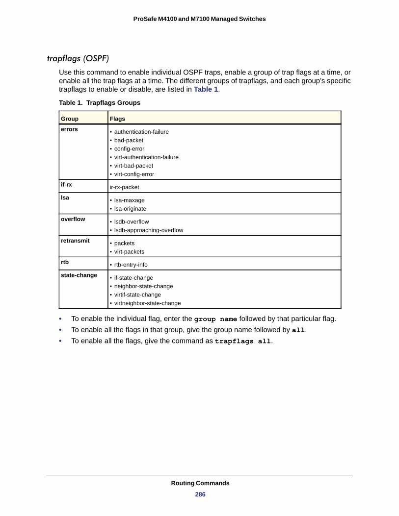
ProSafe M4100 and M7100 Managed Switches
trapflags (OSPF)
Use this command to enable individual OSPF traps, enable a group of trap flags at a time, or enable all the trap flags at a time. The different groups of trapflags, and each group’s specific trapflags to enable or disable, are listed in Table 1.
Table 1. Trapflags Groups
errors • authentication-failure• bad-packet• config-error• virt-authentication-failure• virt-bad-packet• virt-config-error
if-rx
lsa • lsa-maxage• lsa-originate
overflow • lsdb-overflow• lsdb-approaching-overflow
retransmit • packets• virt-packets
rtb • rtb-entry-info
state-change • if-state-change• neighbor-state-change• virtif-state-change• virtneighbor-state-change
• To enable the individual flag, enter the group name followed by that particular flag.• To enable all the flags in that group, give the group name followed by all.• To enable all the flags, give the command as trapflags all.
Group Flags
ir-rx-packet
Routing Commands
286
ProSafe M4100 and M7100 Managed Switches
no trapflags
Use this command to revert to the default reference bandwidth.
• To disable the individual flag, enter the group name followed by that particular flag.• To disable all the flags in that group, give the group name followed by all.• To disable all the flags, give the command as trapflags all.
Default disabled
Format trapflags { all | errors {all | authentication-failure | bad-packet | config-error | virt- authentication-failure | virt-bad-packet | virt-config-error} | if-rx {all | if-rx-packet} | lsa {all | lsa-maxage | lsa-originate} | overflow {all | lsdb-overflow | lsdb-approaching-overflow} | retransmit {all | packets | virt-packets} |rtb {all, rtb-entry-info} | state-change {all | if-state-change | neighbor-state-change | virtif-state- change | virtneighbor-state-change} }
Mode Router OSPF Config
Format no trapflags { all | errors {all | authentication-failure | bad-packet | config-error | virt- authentication-failure | virt-bad-packet | virt-config-error} | if-rx {all | if-rx-packet} | lsa {all | lsa-maxage | lsa-originate} | overflow {all | lsdb-overflow | lsdb-approaching-overflow} | retransmit {all | packets | virt-packets} |rtb {all, rtb-entry-info} | state-change {all | if-state-change | neighbor-state-change | virtif-state- change | virtneighbor-state-change} }
Mode Router OSPF Config
Routing Commands
287
ProSafe M4100 and M7100 Managed Switches
show ip ospf
This command displays information relevant to the OSPF router.
Format show ip ospf
Mode
Note: Some of the information below displays only if you enable OSPF and configure certain features.
Privileged EXEC
Term Definition
Router ID A 32-bit integer in dotted decimal format identifying the router, about which information is displayed. This is a configured value.
OSPF Admin Mode Shows whether the administrative mode of OSPF in the router is enabled or disabled.
This is a configured value.
ASBR Mode Indicates whether the ASBR mode is enabled or disabled. Enable implies that the router is an autonomous system border router. Router automatically becomes an ASBR when it is configured to redistribute routes learnt from other protocol. The possible values for the ASBR status is enabled (if the router is configured to redistribute routes learned by other protocols) or disabled (if the router is not configured for the same).
RFC 1583 Compatibility Indicates whether 1583 compatibility is enabled or disabled. This is a configured value.
External LSDB Limit The maximum number of non-default AS-external-LSA (link state advertisement) entries
that can be stored in the link-state database.
Exit Overflow Interval The number of seconds that, after entering overflow state, a router will attempt to leave
overflow state.
Spf Delay Time The number of seconds between two subsequent changes of LSAs, during which time the routing table calculation is delayed.
Spf Hold Time The number of seconds between two consecutive spf calculations.
Flood Pacing Interval The average time, in milliseconds, between LS Update packet transmissions on an
interface. This is the value configured with the timers pacing flood command.
LSA Refresh Group Pacing Time
The size, in seconds, of the LSA refresh group window. This is the value configured with the timers pacing lsa-group command.
Opaque Capability Shows whether the router is capable of sending Opaque LSAs. This is a configured
value.
Autocost Ref BW Shows the value of auto-cost reference bandwidth configured on the router.
ABR Status Shows whether the router is an OSPF Area Border Router.
Routing Commands
288
ProSafe M4100 and M7100 Managed Switches
ASBR Status Reflects whether the ASBR mode is enabled or disabled. Enable implies that the router is an autonomous system border router. The router automatically becomes an ASBR when it is configured to redistribute routes learnt from other protocols. The possible values for the ASBR status is enabled (if the router is configured to redistribute routes learned by other protocols) or disabled (if the router is not configured for the same).
Stub Router When OSPF runs out of resources to store the entire link state database, or any other state information, OSPF goes into stub router mode. As a stub router, OSPF reoriginates its own router LSAs, setting the cost of all nonstub interfaces to infinity. To restore OSPF to normal operation, disable and reenable OSPF.
Exit Overflow Interval The number of seconds that, after entering overflow state, a router will attempt to leave
overflow state.
External LSDB Overflow When the number of non-default external LSAs exceeds the configured limit, External
LSDB Limit, OSPF goes into LSDB overflow state. In this state, OSPF withdraws all of its self-originated non-default external LSAs. After the Exit Overflow Interval, OSPF leaves the overflow state, if the number of external LSAs has been reduced.
External LSA Count The number of external (LS type 5) link-state advertisements in the link-state database.
External LSA Checksum The sum of the LS checksums of external link-state advertisements contained in the
link-state database.
AS_OPAQUE LSA Count Shows the number of AS Opaque LSAs in the link-state database.
AS_OPAQUE LSA Checksum Shows the sum of the LS Checksums of AS Opaque LSAs contained in the link-state
database.
New LSAs Originated The number of new link-state advertisements that have been originated.
LSAs Received The number of link-state advertisements received determined to be new instantiations.
LSA Count The total number of link state advertisements currently in the link state database.
Maximum Number of LSAs
The maximum number of LSAs that OSPF can store.
LSA High Water Mark The maximum size of the link state database since the system started.
Retransmit List Entries The total number of LSAs waiting to be acknowledged by all neighbors. An LSA might be
pending acknowledgment from more than one neighbor.
Maximum Number of Retransmit Entries
The maximum number of LSAs that can be waiting for acknowledgment at any given time.
Retransmit Entries High Water Mark
The highest number of LSAs that have been waiting for acknowledgment.
External LSDB Limit The maximum number of non-default AS-external-LSAs entries that can be stored in the
link-state database.
Default Metric Default value for redistributed routes.
Term Definition
Routing Commands
289
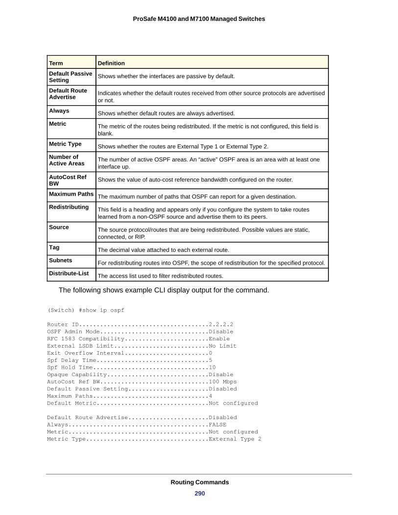
ProSafe M4100 and M7100 Managed Switches
The following shows example CLI display output for the command.
(Switch) #show ip ospf
Router ID.....................................2.2.2.2OSPF Admin Mode...............................DisableRFC 1583 Compatibility........................EnableExternal LSDB Limit...........................No LimitExit Overflow Interval........................0Spf Delay Time................................5Spf Hold Time.................................10Opaque Capability.............................DisableAutoCost Ref BW...............................100 MbpsDefault Passive Setting.......................DisabledMaximum Paths.................................4Default Metric................................Not configured
Default Route Advertise.......................DisabledAlways........................................FALSEMetric........................................Not configuredMetric Type...................................External Type 2
Default Passive Setting Shows whether the interfaces are passive by default.
Default Route Advertise Indicates whether the default routes received from other source protocols are advertised
or not.
Always Shows whether default routes are always advertised.
Metric The metric of the routes being redistributed. If the metric is not configured, this field is blank.
Metric Type Shows whether the routes are External Type 1 or External Type 2.
Number of Active Areas The number of active OSPF areas. An “active” OSPF area is an area with at least one
interface up.
AutoCost Ref BW Shows the value of auto-cost reference bandwidth configured on the router.
Maximum Paths The maximum number of paths that OSPF can report for a given destination.
Redistributing This field is a heading and appears only if you configure the system to take routes learned from a non-OSPF source and advertise them to its peers.
Source The source protocol/routes that are being redistributed. Possible values are static, connected, or RIP.
Tag The decimal value attached to each external route.
Subnets For redistributing routes into OSPF, the scope of redistribution for the specified protocol.
Distribute-List The access list used to filter redistributed routes.
Term Definition
Routing Commands
290
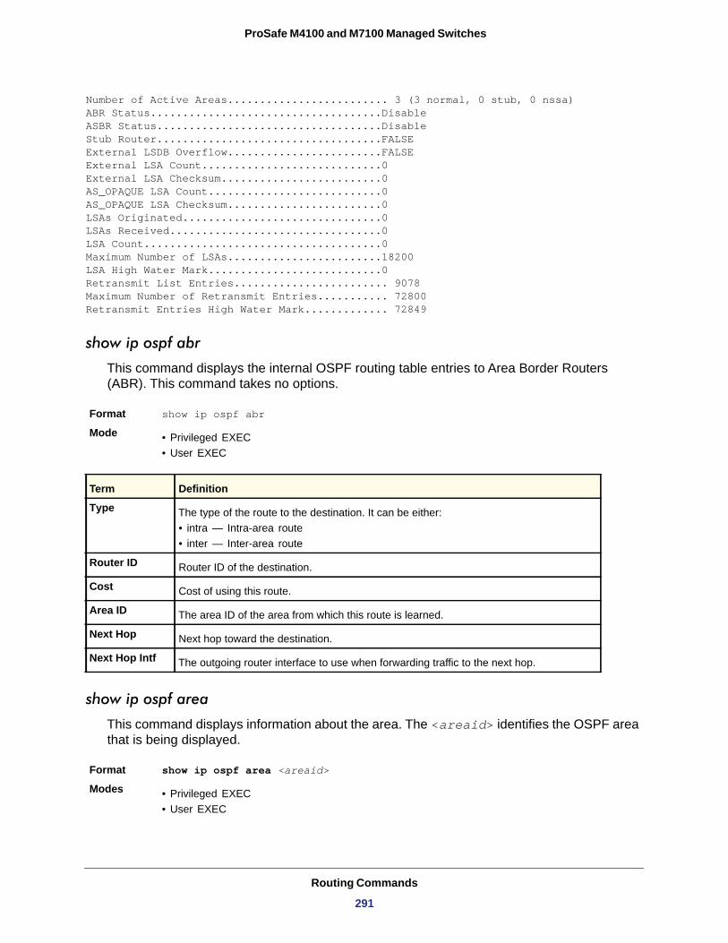
ProSafe M4100 and M7100 Managed Switches
Number of Active Areas......................... 3 (3 normal, 0 stub, 0 nssa) ABR Status....................................DisableASBR Status...................................DisableStub Router...................................FALSE External LSDB Overflow........................FALSE External LSA Count............................0External LSA Checksum.........................0AS_OPAQUE LSA Count...........................0AS_OPAQUE LSA Checksum........................0LSAs Originated...............................0LSAs Received.................................0LSA Count.....................................0 Maximum Number of LSAs........................18200 LSA High Water Mark...........................0 Retransmit List Entries........................ 9078 Maximum Number of Retransmit Entries........... 72800 Retransmit Entries High Water Mark............. 72849
show ip ospf abr
This command displays the internal OSPF routing table entries to Area Border Routers (ABR). This command takes no options.
Format show ip ospf abr
Mode • Privileged EXEC• User EXEC
Type
• intra — Intra-area route• inter — Inter-area route
Router ID
Cost
Area ID
Next Hop
Next Hop Intf
show ip ospf area
This command displays information about the area. The <areaid> identifies the OSPF area that is being displayed.
Format show ip ospf area <areaid>
Modes • Privileged EXEC• User EXEC
Term Definition
The type of the route to the destination. It can be either:
Router ID of the destination.
Cost of using this route.
The area ID of the area from which this route is learned.
Next hop toward the destination.
The outgoing router interface to use when forwarding traffic to the next hop.
Routing Commands
291
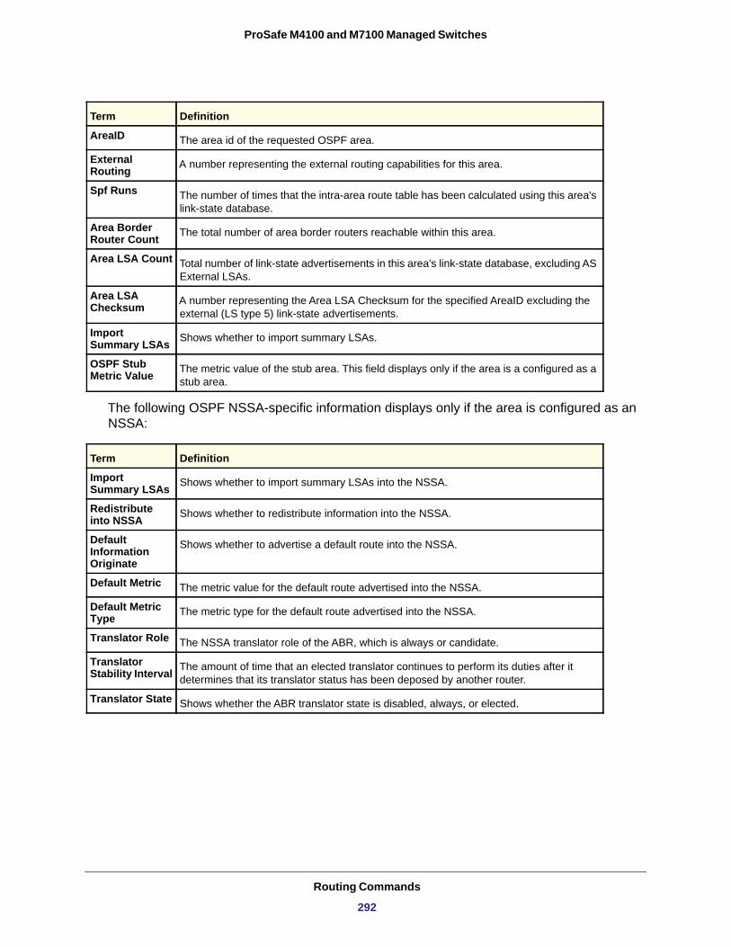
ProSafe M4100 and M7100 Managed Switches
AreaID
External Routing
Spf Runs
Area Border Router Count
Area LSA Count
Area LSA Checksum
Import Summary LSAs
OSPF Stub Metric Value
The following OSPF NSSA-specific information displays only if the area is configured as an NSSA:
Import Summary LSAs
Redistribute into NSSA
Default Information Originate
Default Metric
Default Metric Type
Translator Role
Translator Stability Interval
Translator State
Term Definition
The area id of the requested OSPF area.
A number representing the external routing capabilities for this area.
The number of times that the intra-area route table has been calculated using this area's link-state database.
The total number of area border routers reachable within this area.
Total number of link-state advertisements in this area's link-state database, excluding AS External LSAs.
A number representing the Area LSA Checksum for the specified AreaID excluding the external (LS type 5) link-state advertisements.
Shows whether to import summary LSAs.
The metric value of the stub area. This field displays only if the area is a configured as a stub area.
Term Definition
Shows whether to import summary LSAs into the NSSA.
Shows whether to redistribute information into the NSSA.
Shows whether to advertise a default route into the NSSA.
The metric value for the default route advertised into the NSSA.
The metric type for the default route advertised into the NSSA.
The NSSA translator role of the ABR, which is always or candidate.
The amount of time that an elected translator continues to perform its duties after it determines that its translator status has been deposed by another router.
Shows whether the ABR translator state is disabled, always, or elected.
Routing Commands
292
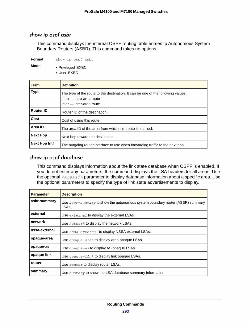
ProSafe M4100 and M7100 Managed Switches
show ip ospf asbr
This command displays the internal OSPF routing table entries to Autonomous System Boundary Routers (ASBR). This command takes no options.
Format show ip ospf asbr
Mode • Privileged EXEC• User EXEC
Type
Router ID
Cost
Area ID
Next Hop
Next Hop Intf
show ip ospf database
This command displays information about the link state database when OSPF is enabled. If you do not enter any parameters, the command displays the LSA headers for all areas. Use the optional <areaid> parameter to display database information about a specific area. Use the optional parameters to specify the type of link state advertisements to display.
Term Definition
The type of the route to the destination. It can be one of the following values:intra — Intra-area routeinter — Inter-area route
Router ID of the destination.
Cost of using this route.
The area ID of the area from which this route is learned.
Next hop toward the destination.
The outgoing router interface to use when forwarding traffic to the next hop.
Parameter Description
asbr-summary Use asbr-summary to show the autonomous system boundary router (ASBR) summary LSAs.
external Use external to display the external LSAs.
network Use network to display the network LSAs.
nssa-external Use nssa-external to display NSSA external LSAs.
opaque-area Use opaque-area to display area opaque LSAs.
opaque-as Use opaque-as to display AS opaque LSAs.
opaque-link Use opaque-link to display link opaque LSAs.
router Use router to display router LSAs.
summary Use summary to show the LSA database summary information.
Routing Commands
293
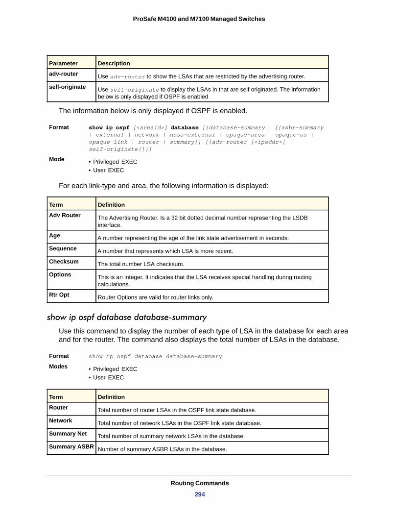
ProSafe M4100 and M7100 Managed Switches
The information below is only displayed if OSPF is enabled.
Format show ip ospf [<areaid>] database [{database-summary | [{asbr-summary | external | network | nssa-external | opaque-area | opaque-as | opaque-link | router | summary}] [{adv-router [<ipaddr>] | self-originate}]}]
Mode • Privileged EXEC• User EXEC
For each link-type and area, the following information is displayed:
Adv Router
Age
Sequence
Checksum
Options
Rtr Opt
show ip ospf database database-summary
Use this command to display the number of each type of LSA in the database for each area and for the router. The command also displays the total number of LSAs in the database.
Format show ip ospf database database-summary
Modes • Privileged EXEC• User EXEC
adv-router Use adv-router to show the LSAs that are restricted by the advertising router.
self-originate Use self-originate to display the LSAs in that are self originated. The information below is only displayed if OSPF is enabled
Term Definition
The Advertising Router. Is a 32 bit dotted decimal number representing the LSDB interface.
A number representing the age of the link state advertisement in seconds.
A number that represents which LSA is more recent.
The total number LSA checksum.
This is an integer. It indicates that the LSA receives special handling during routing calculations.
Router Options are valid for router links only.
Term Definition
Router Total number of router LSAs in the OSPF link state database.
Network Total number of network LSAs in the OSPF link state database.
Summary Net Total number of summary network LSAs in the database.
Summary ASBR Number of summary ASBR LSAs in the database.
Parameter Description
Routing Commands
294
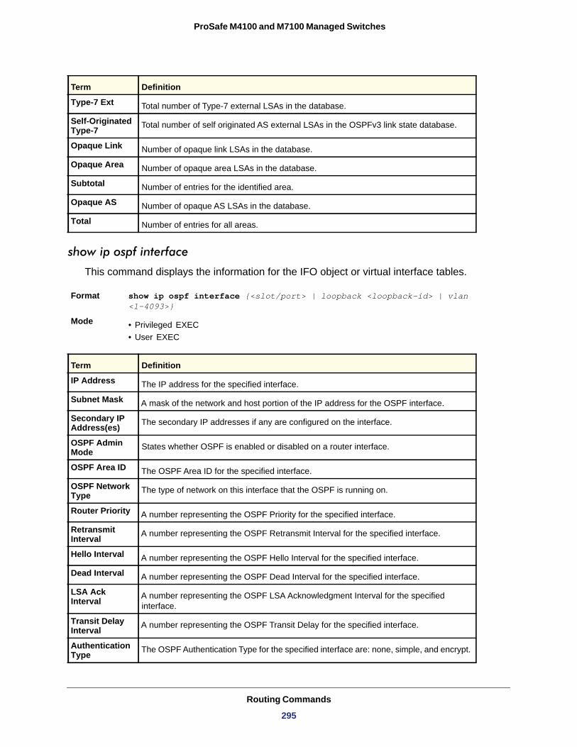
ProSafe M4100 and M7100 Managed Switches
show ip ospf interface
This command displays the information for the IFO object or virtual interface tables.
Format show ip ospf interface {<slot/port> | loopback <loopback-id> | vlan <1-4093>}
Mode • Privileged EXEC• User EXEC
Type-7 Ext Total number of Type-7 external LSAs in the database.
Self-Originated Type-7 Total number of self originated AS external LSAs in the OSPFv3 link state database.
Opaque Link Number of opaque link LSAs in the database.
Opaque Area Number of opaque area LSAs in the database.
Subtotal Number of entries for the identified area.
Opaque AS Number of opaque AS LSAs in the database.
Total Number of entries for all areas.
Term Definition
IP Address The IP address for the specified interface.
Subnet Mask A mask of the network and host portion of the IP address for the OSPF interface.
Secondary IP Address(es) The secondary IP addresses if any are configured on the interface.
OSPF Admin Mode States whether OSPF is enabled or disabled on a router interface.
OSPF Area ID The OSPF Area ID for the specified interface.
OSPF Network Type The type of network on this interface that the OSPF is running on.
Router Priority A number representing the OSPF Priority for the specified interface.
Retransmit Interval A number representing the OSPF Retransmit Interval for the specified interface.
Hello Interval A number representing the OSPF Hello Interval for the specified interface.
Dead Interval A number representing the OSPF Dead Interval for the specified interface.
LSA Ack Interval A number representing the OSPF LSA Acknowledgment Interval for the specified
interface.
Transit Delay Interval A number representing the OSPF Transit Delay for the specified interface.
Authentication Type The OSPF Authentication Type for the specified interface are: none, simple, and encrypt.
Term Definition
Routing Commands
295
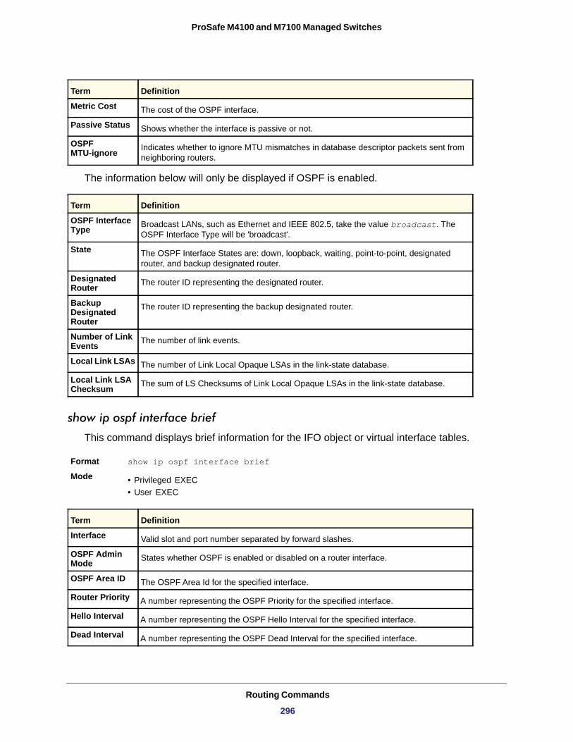
ProSafe M4100 and M7100 Managed Switches
The information below will only be displayed if OSPF is enabled.
OSPF Interface Type
State
Designated Router
Backup Designated Router
Number of Link Events
Local Link LSAs
Local Link LSA Checksum
show ip ospf interface brief
This command displays brief information for the IFO object or virtual interface tables.
Format show ip ospf interface brief
Mode • Privileged EXEC• User EXEC
Metric Cost The cost of the OSPF interface.
Passive Status Shows whether the interface is passive or not.
OSPF MTU-ignore Indicates whether to ignore MTU mismatches in database descriptor packets sent from
neighboring routers.
Term Definition
Broadcast LANs, such as Ethernet and IEEE 802.5, take the value broadcast. The OSPF Interface Type will be 'broadcast'.
The OSPF Interface States are: down, loopback, waiting, point-to-point, designated router, and backup designated router.
The router ID representing the designated router.
The router ID representing the backup designated router.
The number of link events.
The number of Link Local Opaque LSAs in the link-state database.
The sum of LS Checksums of Link Local Opaque LSAs in the link-state database.
Term Definition
Interface Valid slot and port number separated by forward slashes.
OSPF Admin Mode States whether OSPF is enabled or disabled on a router interface.
OSPF Area ID The OSPF Area Id for the specified interface.
Router Priority A number representing the OSPF Priority for the specified interface.
Hello Interval A number representing the OSPF Hello Interval for the specified interface.
Dead Interval A number representing the OSPF Dead Interval for the specified interface.
Term Definition
Routing Commands
296

ProSafe M4100 and M7100 Managed Switches
show ip ospf interface stats
This command displays the statistics for a specific interface. The information below will only be displayed if OSPF is enabled.
Format show ip ospf interface stats <slot/port>
Modes • Privileged EXEC• User EXEC
Retransmit Interval A number representing the OSPF Retransmit Interval for the specified interface.
Retransmit Delay Interval A number representing the OSPF Transit Delay for the specified interface.
LSA Ack Interval A number representing the OSPF LSA Acknowledgment Interval for the specified
interface.
Term Definition
OSPF Area ID The area id of this OSPF interface.
Area Border Router Count The total number of area border routers reachable within this area. This is initially zero,
and is calculated in each SPF pass.
AS Border Router Count The total number of Autonomous System border routers reachable within this area.
Area LSA Count The total number of link-state advertisements in this area's link-state database, excluding AS External LSAs.
IP Address The IP address associated with this OSPF interface.
OSPF Interface Events The number of times the specified OSPF interface has changed its state, or an error has
occurred.
Virtual Events The number of state changes or errors that occurred on this virtual link.
Neighbor Events The number of times this neighbor relationship has changed state, or an error has
occurred.
External LSA Count The number of external (LS type 5) link-state advertisements in the link-state database.
Sent Packets The number of OSPF packets transmitted on the interface.
Received Packets The number of valid OSPF packets received on the interface.
Discards The number of received OSPF packets discarded because of an error in the packet or an error in processing the packet.
Bad Version The number of received OSPF packets whose version field in the OSPF header does not match the version of the OSPF process handling the packet.
Term Definition
Routing Commands
297
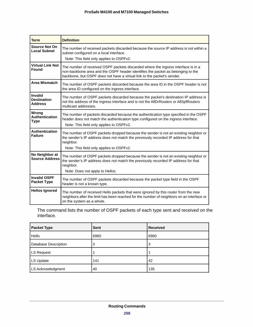
ProSafe M4100 and M7100 Managed Switches
The command lists the number of OSPF packets of each type sent and received on the interface.
Source Not On Local Subnet The number of received packets discarded because the source IP address is not within a
subnet configured on a local interface. Note: This field only applies to OSPFv2.
Virtual Link Not Found The number of received OSPF packets discarded where the ingress interface is in a
non-backbone area and the OSPF header identifies the packet as belonging to the backbone, but OSPF does not have a virtual link to the packet’s sender.
Area Mismatch The number of OSPF packets discarded because the area ID in the OSPF header is not the area ID configured on the ingress interface.
Invalid Destination Address
The number of OSPF packets discarded because the packet’s destination IP address is not the address of the ingress interface and is not the AllDrRouters or AllSpfRouters multicast addresses.
Wrong Authentication Type
The number of packets discarded because the authentication type specified in the OSPF header does not match the authentication type configured on the ingress interface.
Note: This field only applies to OSPFv2.
Authentication Failure The number of OSPF packets dropped because the sender is not an existing neighbor or
the sender’s IP address does not match the previously recorded IP address for that neighbor.
Note: This field only applies to OSPFv2.
No Neighbor at Source Address The number of OSPF packets dropped because the sender is not an existing neighbor or
the sender’s IP address does not match the previously recorded IP address for that neighbor.
Note: Does not apply to Hellos.
Invalid OSPF Packet Type The number of OSPF packets discarded because the packet type field in the OSPF
header is not a known type.
Hellos Ignored The number of received Hello packets that were ignored by this router from the new neighbors after the limit has been reached for the number of neighbors on an interface or on the system as a whole.
Packet Type Sent Received
Hello 6960 6960
Database Description 3 3
LS Request 1 1
LS Update 141 42
LS Acknowledgment 40 135
Term Definition
Routing Commands
298
ProSafe M4100 and M7100 Managed Switches
show ip ospf neighbor
This command displays information about OSPF neighbors. If you do not specify a neighbor IP address, the output displays summary information in a table. If you specify an interface or tunnel, only the information for that interface or tunnel displays. The <ip-address> is the IP address of the neighbor, and when you specify this, detailed information about the neighbor displays. The information below only displays if OSPF is enabled and the interface has a neighbor.
Format show ip ospf neighbor [interface <slot/port>] [<ip-address>]
Modes • Privileged EXEC• User EXEC
If you do not specify an IP address, a table with the following columns displays for all neighbors or the neighbor associated with the interface that you specify:
Router ID
Priority
IP Address
Neighbor Interface
State
• Down - initial state of the neighbor conversation - no recent information has been received from the neighbor.
• Attempt - no recent information has been received from the neighbor but a more concerted effort should be made to contact the neighbor.
• Init - an Hello packet has recently been seen from the neighbor, but bidirectional communication has not yet been established.
• 2 way - communication between the two routers is bidirectional.• Exchange start - the first step in creating an adjacency between the two neighboring
routers, the goal is to decide which router is the master and to decide upon the initial DD sequence number.
• Exchange - the router is describing its entire link state database by sending Database Description packets to the neighbor.
• Loading - Link State Request packets are sent to the neighbor asking for the more recent LSAs that have been discovered (but not yet received) in the Exchange state.
• Full - the neighboring routers are fully adjacent and they will now appear in router-LSAs and network-LSAs.
Dead Time
Term Definition
The 4-digit dotted-decimal number of the neighbor router.
The OSPF priority for the specified interface. The priority of an interface is a priority integer from 0 to 255. A value of '0' indicates that the router is not eligible to become the designated router on this network.
The IP address of the neighbor.
The interface of the local router in slot/port format.
The state of the neighboring routers. The possible values are:
The amount of time, in seconds, to wait before the router assumes that the neighbor is unreachable.
Routing Commands
299
ProSafe M4100 and M7100 Managed Switches
If you specify an IP address for the neighbor router, the following fields display:
Interface
Neighbor IP Address
Interface Index
Area ID
Options
Router Priority
Dead Timer Due
Up Time
State
Events
Retransmission Queue Length
The following shows example CLI display output for the command.
(Switch) #show ip ospf neighbor 170.1.1.50
Interface.....................................0/17Neighbor IP Address...........................170.1.1.50Interface Index...............................17Area Id.......................................0.0.0.2Options.......................................0x2Router Priority...............................1Dead timer due in (secs)......................15Up Time.......................................0 days 2 hrs 8 mins 46 secsState.........................................Full/BACKUP-DREvents........................................4Retransmission Queue Length...................0
Term Definition
Valid slot and port number separated by forward slashes.
The IP address of the neighbor router.
The interface ID of the neighbor router.
The area ID of the OSPF area associated with the interface.
An integer value that indicates the optional OSPF capabilities supported by the neighbor. The neighbor's optional OSPF capabilities are also listed in its Hello packets. This enables received Hello Packets to be rejected (that is, neighbor relationships will not even start to form) if there is a mismatch in certain crucial OSPF capabilities.
The OSPF priority for the specified interface. The priority of an interface is a priority integer from 0 to 255. A value of '0' indicates that the router is not eligible to become the designated router on this network.
The amount of time, in seconds, to wait before the router assumes that the neighbor is unreachable.
Neighbor uptime; how long since the adjacency last reached the Full state.
The state of the neighboring routers.
The number of times this neighbor relationship has changed state, or an error has occurred.
An integer representing the current length of the retransmission queue of the specified neighbor router Id of the specified interface.
Routing Commands
300
ProSafe M4100 and M7100 Managed Switches
show ip ospf range
This command displays information about the area ranges for the specified <areaid>. The <areaid> identifies the OSPF area whose ranges are being displayed.
Format show ip ospf range <areaid>
Modes • Privileged EXEC• User EXEC
Area ID
IP Address
Subnet Mask
Lsdb Type
Advertisement
show ip ospf statistics
This command displays information about recent Shortest Path First (SPF) calculations. The SPF is the OSPF routing table calculation. The output lists the number of times the SPF has run for each OSPF area. A table follows this information. For each of the 15 most recent SPF runs, the table lists how long ago the SPF ran, how long the SPF took, and the reasons why the SPF was scheduled.
Format show ip ospf statistics
Modes • Privileged EXEC• User EXEC
Delta T
SPF Duration
Reason
• R - a router LSA has changed• N - a network LSA has changed• SN - a type 3 network summary LSA has changed• SA - a type 4 ASBR summary LSA has changed• X - a type 5 or type 7 external LSA has changed
Term Definition
The area id of the requested OSPF area.
An IP address which represents this area range.
A valid subnet mask for this area range.
The type of link advertisement associated with this area range.
The status of the advertisement. Advertisement has two possible settings: enabled or disabled.
Term Definition
How long ago the SPF ran. The time is in the format hh:mm:ss, giving the hours, minutes, and seconds since the SPF run.
How long the SPF took in milliseconds.
The reason the SPF was scheduled. Reason codes are as follows:
Routing Commands
301
ProSafe M4100 and M7100 Managed Switches
show ip ospf stub table
This command displays the OSPF stub table. The information below will only be displayed if OSPF is initialized on the switch.
Format show ip ospf stub table
Modes • Privileged EXEC• User EXEC
Area ID
Type of Service
Metric Val
Import Summary LSA
show ip ospf traffic
This command displays OSPFv2 packet and LSA statistics and OSPFv2 message queue statistics. Packet statistics count the packets and LSAs since OSPFv2 counters were last cleared (using the command clear ip ospf counters).
Note: The clear ip ospf counters command does not clear the message queue high water marks.
Format show ip ospf traffic
Mode
Term Definition
A 32-bit identifier for the created stub area.
The Type of Service associated with the stub metric. Switch CLI only supports Normal TOS.
The metric value is applied based on the TOS. It defaults to the least metric of the Type of Service among the interfaces to other areas. The OSPF cost for a route is a function of the metric value.
Controls the import of summary LSAs into stub areas.
Privileged EXEC
Parameter Description
OSPFv2 Packet Statistics
The number of packets of each type sent and received since OSPF counters were last cleared.
LSAs Retransmitted
The number of LSAs retransmitted by this router since OSPF counters were last cleared.
LS Update Max Receive Rate
The maximum rate of LS Update packets received during any 5-second interval since OSPF counters were last cleared. The rate is in packets per second.
LS Update Max Send Rate
The maximum rate of LS Update packets transmitted during any 5-second interval since OSPF counters were last cleared. The rate is in packets per second.
Routing Commands
302
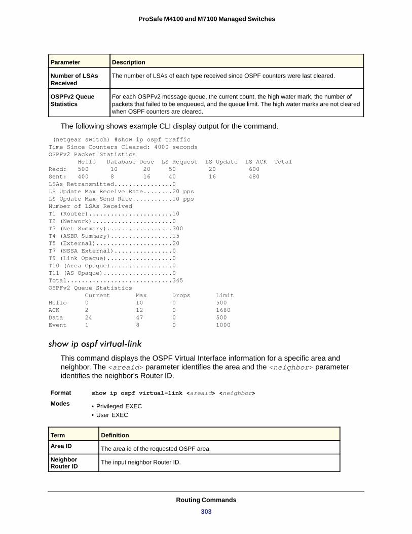
ProSafe M4100 and M7100 Managed Switches
The following shows example CLI display output for the command.
(netgear switch) #show ip ospf trafficTime Since Counters Cleared: 4000 seconds OSPFv2 Packet Statistics Hello Database Desc LS Request LS Update LS ACK Total Recd: 500 10 20 50 20 600 Sent: 400 8 16 40 16 480LSAs Retransmitted................0 LS Update Max Receive Rate........20 pps LS Update Max Send Rate...........10 pps Number of LSAs Received T1 (Router).......................10 T2 (Network)......................0 T3 (Net Summary)..................300 T4 (ASBR Summary).................15 T5 (External).....................20 T7 (NSSA External)................0 T9 (Link Opaque)..................0 T10 (Area Opaque).................0 T11 (AS Opaque)...................0 Total.............................345OSPFv2 Queue Statistics Current Max Drops Limit Hello 0 10 0 500 ACK 2 12 0 1680 Data 24 47 0 500 Event 1 8 0 1000
show ip ospf virtual-link
This command displays the OSPF Virtual Interface information for a specific area and neighbor. The <areaid> parameter identifies the area and the <neighbor> parameter identifies the neighbor's Router ID.
Format show ip ospf virtual-link <areaid> <neighbor>
Modes • Privileged EXEC• User EXEC
Number of LSAs Received
The number of LSAs of each type received since OSPF counters were last cleared.
OSPFv2 Queue Statistics
For each OSPFv2 message queue, the current count, the high water mark, the number of packets that failed to be enqueued, and the queue limit. The high water marks are not cleared when OSPF counters are cleared.
Term Definition
Area ID The area id of the requested OSPF area.
Neighbor Router ID The input neighbor Router ID.
Parameter Description
Routing Commands
303
ProSafe M4100 and M7100 Managed Switches
show ip ospf virtual-link brief
This command displays the OSPF Virtual Interface information for all areas in the system.
Format show ip ospf virtual-link brief
Modes • Privileged EXEC• User EXEC
Area ID
Neighbor
Hello Interval
Dead Interval
Retransmit Interval
Transit Delay
OSPF Graceful Restart Commands
The OSPF protocol can be configured to participate in the checkpointing service, so that these protocols can execute a graceful restart when the management unit fails. In a graceful restart, the hardware to continues forwarding IPv4 packets using OSPF routes, while a backup switch takes over management unit responsibility.
Graceful restart uses the concept of “helpful neighbors.” A fully adjacent router enters helper mode when it receives a link state announcement (LSA) from the restarting management unit indicating its intention of performing a graceful restart. In helper mode, a switch continues to advertise to the rest of the network that they have full adjacencies with the restarting router,
Hello Interval The configured hello interval for the OSPF virtual interface.
Dead Interval The configured dead interval for the OSPF virtual interface.
Iftransit Delay Interval The configured transit delay for the OSPF virtual interface.
Retransmit Interval The configured retransmit interval for the OSPF virtual interface.
Authentication Type The configured authentication type of the OSPF virtual interface.
State The OSPF Interface States are: down, loopback, waiting, point-to-point, designated router, and backup designated router. This is the state of the OSPF interface.
Neighbor State The neighbor state.
Term Definition
The area id of the requested OSPF area.
The neighbor interface of the OSPF virtual interface.
The configured hello interval for the OSPF virtual interface.
The configured dead interval for the OSPF virtual interface.
The configured retransmit interval for the OSPF virtual interface.
The configured transit delay for the OSPF virtual interface.
Term Definition
Routing Commands
304
ProSafe M4100 and M7100 Managed Switches
avoiding announcement of a topology change and the potential for flooding of LSAs and shortest-path-first (SPF) runs, which determine OSPF routes. Helpful neighbors continue to forward packets through the restarting router. The restarting router relearns the network topology from its helpful neighbors.
Graceful restart can be enabled for planned or unplanned restarts, or both. A planned restart is initiated by the operator through the management command initiate failover. The operator might initiate a failover to take the management unit out of service (for example, to address a partial hardware failure), to correct faulty system behavior that cannot be corrected through less severe management actions, or other reasons. An unplanned restart is an unexpected failover, caused by a fatal hardware failure of the management unit or a software hang or crash on the management unit.
nsf Use this command to enable the OSPF graceful restart functionality on an interface. To disable graceful restart, use the no form of the command.
no nsf
Use this command to disable graceful restart for all restarts.
nsf restart-interval Use this command to configure the number of seconds that the restarting router asks its neighbors to wait before exiting helper mode. This is called the “grace period.” The restarting router includes the grace period in its grace LSAs. For planned restarts (using the initiate failover command), the grace LSAs are sent prior to restarting the management unit, whereas for unplanned restarts, they are sent after reboot begins. The grace period must be
Default Disabled
Format nsf [ietf] [planned-only]
Modes OSPF Router Configuration
Parameter Description
ietf This keyword is accepted but not required.
planned-only This optional keyword indicates that OSPF should perform only a graceful restart when the restart is planned (that is, when the restart is a result of the initiate failover command).
Format no nsf
Modes OSPF Router Configuration
Routing Commands
305
ProSafe M4100 and M7100 Managed Switches
set long enough to allow the restarting router to reestablish all of its adjacencies and complete a full database exchange with each of those neighbors.
no nsfrestart-interval
Use this command to revert the grace period to its default value.
nsf helper Use this command to enable helpful neighbor functionality for the OSPF protocol. You can enable this functionality for planned or unplanned restarts, or both.
no nsf helper
Use this command to disable helpful neighbor functionality for OSPF.
Default 120 seconds
Format nsf [ietf] restart-interval <1-1800>
Modes OSPF Router Configuration
Parameter Description
ietf This keyword is accepted but not required.
seconds The number of seconds that the restarting router asks its neighbors to wait before exiting helper mode. The range is from 1 to 1800 seconds.
Format no [ietf] nsf restart-interval
Modes OSPF Router Configuration
Default OSPF might act as a helpful neighbor for both planned and unplanned restarts
Format nsf [ietf] helper [planned-only]
Modes OSPF Router Configuration
Parameter Description
ietf This keyword is accepted but not required.
planned-only This optional keyword indicates that OSPF should only help a restarting router performing a planned restart.
Format no nsf [ietf] helper
Modes OSPF Router Configuration
Routing Commands
306
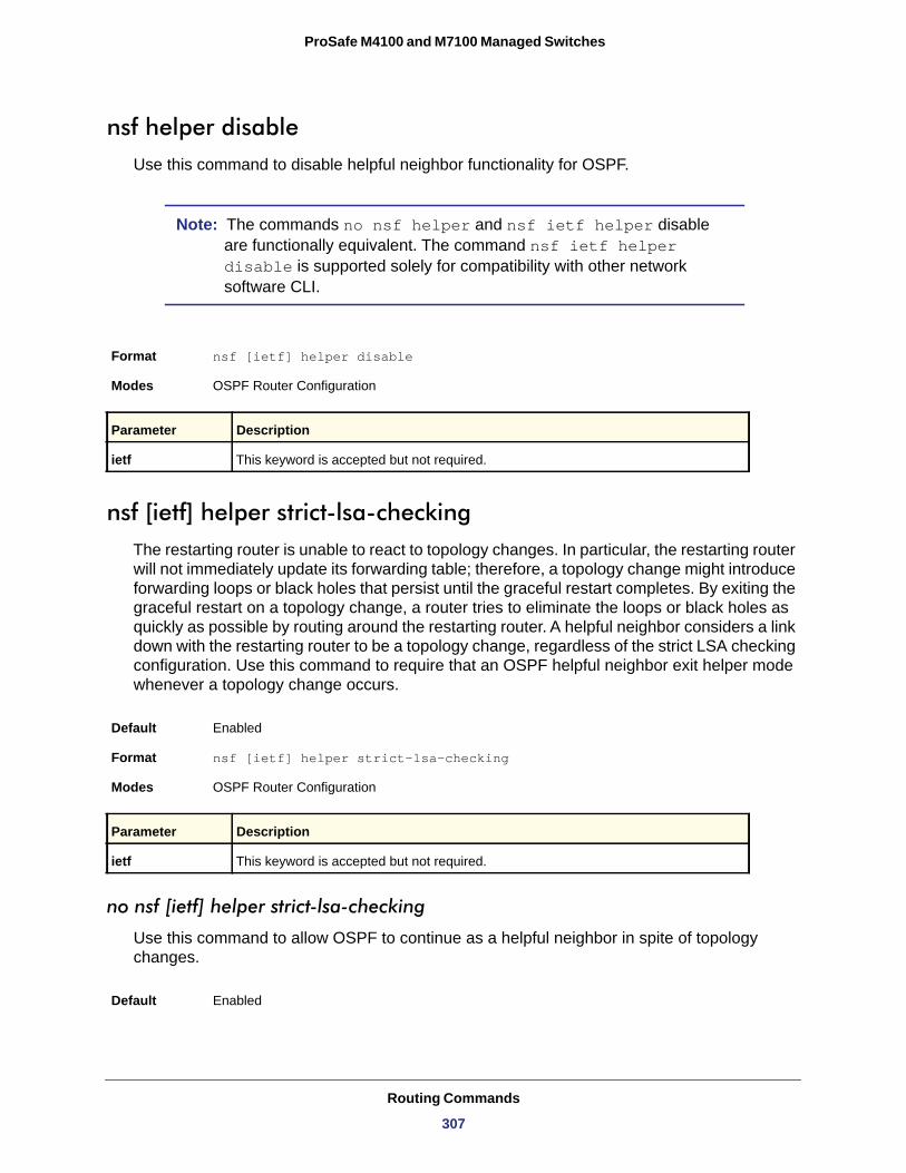
ProSafe M4100 and M7100 Managed Switches
nsf helper disableUse this command to disable helpful neighbor functionality for OSPF.
Note: The commands no nsf helper and nsf ietf helper disable are functionally equivalent. The command nsf ietf helper disable is supported solely for compatibility with other network software CLI.
nsf [ietf] helper strict-lsa-checking The restarting router is unable to react to topology changes. In particular, the restarting router will not immediately update its forwarding table; therefore, a topology change might introduce forwarding loops or black holes that persist until the graceful restart completes. By exiting the graceful restart on a topology change, a router tries to eliminate the loops or black holes as quickly as possible by routing around the restarting router. A helpful neighbor considers a link down with the restarting router to be a topology change, regardless of the strict LSA checking configuration. Use this command to require that an OSPF helpful neighbor exit helper mode whenever a topology change occurs.
no nsf [ietf] helper strict-lsa-checking
Use this command to allow OSPF to continue as a helpful neighbor in spite of topology changes.
Format nsf [ietf] helper disable
Modes OSPF Router Configuration
Parameter Description
ietf This keyword is accepted but not required.
Default Enabled
Format nsf [ietf] helper strict-lsa-checking
Modes OSPF Router Configuration
Parameter Description
ietf This keyword is accepted but not required.
Default Enabled
Routing Commands
307
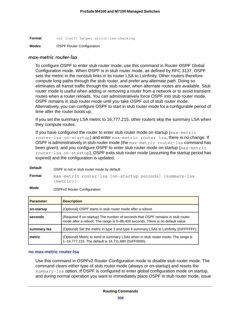
ProSafe M4100 and M7100 Managed Switches
max-metric router-lsa
To configure OSPF to enter stub router mode, use this command in Router OSPF Global Configuration mode. When OSPF is in stub router mode, as defined by RFC 3137, OSPF sets the metric in the nonstub links in its router LSA to LsInfinity. Other routers therefore compute long paths through the stub router, and prefer any alternate path. Doing so eliminates all transit traffic through the stub router, when alternate routes are available. Stub router mode is useful when adding or removing a router from a network or to avoid transient routes when a router reloads. You can administratively force OSPF into stub router mode. OSPF remains in stub router mode until you take OSPF out of stub router mode. Alternatively, you can configure OSPF to start in stub router mode for a configurable period of time after the router boots up.
If you set the summary LSA metric to 16,777,215, other routers skip the summary LSA when they compute routes.
If you have configured the router to enter stub router mode on startup (max-metric router-lsa on-startup) and enter max-metric router lsa, there is no change. If OSPF is administratively in stub router mode (the max-metric router-lsa command has been given), and you configure OSPF to enter stub router mode on startup (max-metric router-lsa on-startup), OSPF exits stub router mode (assuming the startup period has expired) and the configuration is updated.
Default
Format max-metric router-lsa [on-startup seconds] [summary-lsa {metric}]
Mode
no max-metric router-lsa
Use this command in OSPFv2 Router Configuration mode to disable stub router mode. The command clears either type of stub router mode (always or on-startup) and resets the summary-lsa option. If OSPF is configured to enter global configuration mode on startup, and during normal operation you want to immediately place OSPF in stub router mode, issue
Format nsf [ietf] helper strict-lsa-checking
Modes OSPF Router Configuration
OSPF is not in stub router mode by default
OSPFv2 Router Configuration
Parameter Description
on-startup (Optional) OSPF starts in stub router mode after a reboot.
seconds (Required if on-startup) The number of seconds that OSPF remains in stub router mode after a reboot. The range is 5–86,400 seconds. There is no default value.
summary-lsa (Optional) Set the metric in type 3 and type 4 summary LSAs to LsInfinity (0xFFFFFF).
metric (Optional) Metric to send in summary LSAs when in stub router mode. The range is 1–16,777,215. The default is 16,711,680 (0xFF0000).
Routing Commands
308
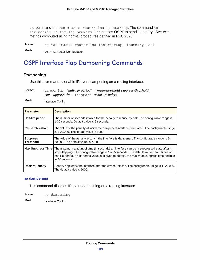
ProSafe M4100 and M7100 Managed Switches
the command no max-metric router-lsa on-startup. The command no max-metric router-lsa summary-lsa causes OSPF to send summary LSAs with metrics computed using normal procedures defined in RFC 2328.
Format no max-metric router-lsa [on-startup] [summary-lsa]
Mode
OSPF Interface Flap Dampening Commands
Dampening
Use this command to enable IP event dampening on a routing interface.
Format dampening [half-life period] [reuse-threshold suppress-threshold max-suppress-time [restart restart-penalty]]
Mode
no dampening
This command disables IP event dampening on a routing interface.
Format no dampening
Mode
OSPFv2 Router Configuration
Interface Config
Parameter Description
Half-life period The number of seconds it takes for the penalty to reduce by half. The configurable range is 1-30 seconds. Default value is 5 seconds.
Reuse Threshold The value of the penalty at which the dampened interface is restored. The configurable range is 1-20,000. The default value is 1000.
Suppress Threshold
The value of the penalty at which the interface is dampened. The configurable range is 1- 20,000. The default value is 2000.
Max Suppress Time The maximum amount of time (in seconds) an interface can be in suppressed state after it stops flapping. The configurable range is 1-255 seconds. The default value is four times of half-life period. If half-period value is allowed to default, the maximum suppress time defaults to 20 seconds.
Restart Penalty Penalty applied to the interface after the device reloads. The configurable range is 1- 20,000. The default value is 2000.
Interface Config
Routing Commands
309
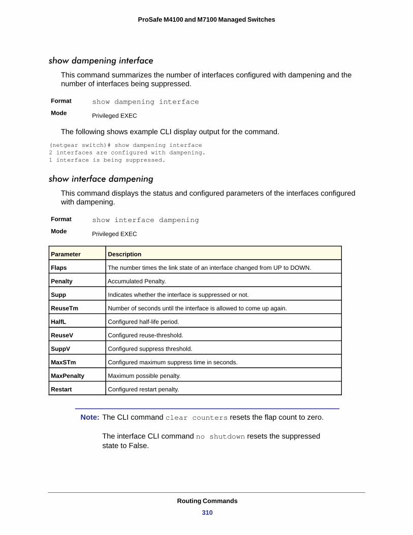
ProSafe M4100 and M7100 Managed Switches
show dampening interface
This command summarizes the number of interfaces configured with dampening and the number of interfaces being suppressed.
Format show dampening interface
Mode
The following shows example CLI display output for the command.
(netgear switch)# show dampening interface 2 interfaces are configured with dampening. 1 interface is being suppressed.
show interface dampening
This command displays the status and configured parameters of the interfaces configured with dampening.
Format show interface dampening
Mode
Note: The CLI command clear counters resets the flap count to zero. The interface CLI command no shutdown resets the suppressed state to False.
Privileged EXEC
Privileged EXEC
Parameter Description
Flaps The number times the link state of an interface changed from UP to DOWN.
Penalty Accumulated Penalty.
Supp Indicates whether the interface is suppressed or not.
ReuseTm Number of seconds until the interface is allowed to come up again.
HalfL Configured half-life period.
ReuseV Configured reuse-threshold.
SuppV Configured suppress threshold.
MaxSTm Configured maximum suppress time in seconds.
MaxPenalty Maximum possible penalty.
Restart Configured restart penalty.
Routing Commands
310
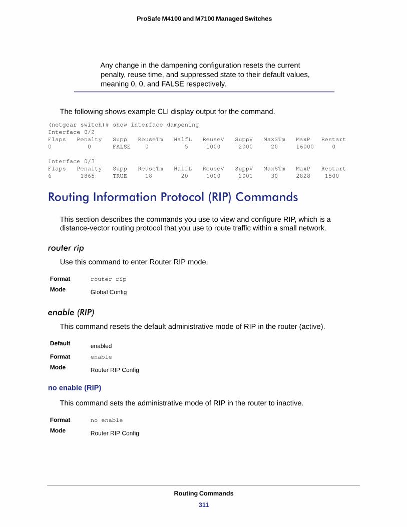
ProSafe M4100 and M7100 Managed Switches
Any change in the dampening configuration resets the current penalty, reuse time, and suppressed state to their default values, meaning 0, 0, and FALSE respectively.
The following shows example CLI display output for the command.
(netgear switch)# show interface dampening Interface 0/2 Flaps Penalty Supp ReuseTm HalfL ReuseV SuppV MaxSTm MaxP Restart 0 0 FALSE 0 5 1000 2000 20 16000 0
Interface 0/3 Flaps Penalty Supp ReuseTm HalfL ReuseV SuppV MaxSTm MaxP Restart 6 1865 TRUE 18 20 1000 2001 30 2828 1500
Routing Information Protocol (RIP) Commands
This section describes the commands you use to view and configure RIP, which is a distance-vector routing protocol that you use to route traffic within a small network.
router rip
Use this command to enter Router RIP mode.
Format router rip
Mode
enable (RIP)
This command resets the default administrative mode of RIP in the router (active).
Default
Format enable
Mode
no enable (RIP)
This command sets the administrative mode of RIP in the router to inactive.
Format no enable
Mode
Global Config
enabled
Router RIP Config
Router RIP Config
Routing Commands
311
ProSafe M4100 and M7100 Managed Switches
ip rip
This command enables RIP on a router interface.
Default
Format ip rip
Mode
no ip rip
This command disables RIP on a router interface.
Format no ip rip
Mode
auto-summary
This command enables the RIP auto-summarization mode.
Default
Format auto-summary
Mode
no auto-summary
This command disables the RIP auto-summarization mode.
Format no auto-summary
Mode
default-information originate (RIP)
This command is used to control the advertisement of default routes.
Format default-information originate
Mode
no default-information originate (RIP)
This command is used to control the advertisement of default routes.
Format no default-information originate
Mode
disabled
Interface Config
Interface Config
disabled
Router RIP Config
Router RIP Config
Router RIP Config
Router RIP Config
Routing Commands
312
ProSafe M4100 and M7100 Managed Switches
default-metric (RIP)
This command is used to set a default for the metric of distributed routes.
Format default-metric <0-15>
Mode
no default-metric (RIP)
This command is used to reset the default metric of distributed routes to its default value.
Format no default-metric
Mode
distance rip
This command sets the route preference value of RIP in the router. Lower route preference values are preferred when determining the best route. A route with a preference of 255 cannot be used to forward traffic.
Default
Format distance rip <1-255>
Mode
no distance rip
This command sets the default route preference value of RIP in the router.
Format no distance rip
Mode
distribute-list out (RIP)
This command is used to specify the access list to filter routes received from the source protocol.
Default
Format distribute-list <1-199> out {ospf | static | connected}
Mode
Router RIP Config
Router RIP Config
15
Router RIP Config
Router RIP Config
0
Router RIP Config
Routing Commands
313
ProSafe M4100 and M7100 Managed Switches
no distribute-list out
This command is used to specify the access list to filter routes received from the source protocol.
Format no distribute-list <1-199> out {ospf | static | connected}
Mode
ip rip authentication
This command sets the RIP Version 2 Authentication Type and Key for the specified interface. The value of <type> is either none, simple, or encrypt. The value for authentication key [key] must be 16 bytes or less. The [key] is composed of standard displayable, non-control keystrokes from a Standard 101/102-key keyboard. If the value of <type> is encrypt, a keyid in the range of 0 and 255 must be specified. Unauthenticated interfaces do not need an authentication key or authentication key ID.
Default
Format ip rip authentication {none | {simple <key>} | {encrypt <key> <keyid>}}
Mode
no ip rip authentication
This command sets the default RIP Version 2 Authentication Type for an interface.
Format no ip rip authentication
Mode
ip rip receive version
This command configures the interface to allow RIP control packets of the specified version(s) to be received.
The value for <mode> is one of: rip1 to receive only RIP version 1 formatted packets, rip2 for RIP version 2, both to receive packets from either format, or none to not allow any RIP control packets to be received.
Default
Format ip rip receive version {rip1 | rip2 | both | none}
Mode
Router RIP Config
none
Interface Config
Interface Config
both
Interface Config
Routing Commands
314
ProSafe M4100 and M7100 Managed Switches
no ip rip receive version
This command configures the interface to allow RIP control packets of the default version(s) to be received.
Format no ip rip receive version
Mode
ip rip send version
This command configures the interface to allow RIP control packets of the specified version to be sent. The value for <mode> is one of: rip1 to broadcast RIP version 1 formatted packets, rip1c (RIP version 1 compatibility mode) which sends RIP version 2 formatted packets via broadcast, rip2 for sending RIP version 2 using multicast, or none to not allow any RIP control packets to be sent.
Default
Format ip rip send version {rip1 | rip1c | rip2 | none}
Mode
no ip rip send version
This command configures the interface to allow RIP control packets of the default version to be sent.
Format no ip rip send version
Mode
hostroutesaccept
This command enables the RIP hostroutesaccept mode.
Default
Format hostroutesaccept
Mode
no hostroutesaccept
This command disables the RIP hostroutesaccept mode.
Format no hostroutesaccept
Mode
Interface Config
ripi2
Interface Config
Interface Config
enabled
Router RIP Config
Router RIP Config
Routing Commands
315
ProSafe M4100 and M7100 Managed Switches
split-horizon
This command sets the RIP split horizon mode. Split horizon is a technique for avoiding problems caused by including routes in updates sent to the router from which the route was originally learned. The options are: None - no special processing for this case. Simple - a route will not be included in updates sent to the router from which it was learned. Poisoned reverse - a route will be included in updates sent to the router from which it was learned, but the metric will be set to infinity.
Default
Format split-horizon {none | simple | poison}
Mode
no split-horizon
This command sets the default RIP split horizon mode.
Format no split-horizon
Mode
redistribute (RIP)
This command configures RIP protocol to redistribute routes from the specified source protocol/routers. There are five possible match options. When you submit the command redistribute ospf match <match-type> the match-type or types specified are added to any match types presently being redistributed. Internal routes are redistributed by default.
Default • metric—not-configured• match—internal
Format for OSPF as source protocol
redistribute ospf [metric <0-15>] [match [internal] [external 1] [external 2] [nssa-external 1] [nssa-external-2]]
Format for other source protocol
redistribute {static | connected} [metric <0-15>]
Mode
no redistribute
This command de-configures RIP protocol to redistribute routes from the specified source protocol/routers.
Format no redistribute {ospf | static | connected} [metric] [match [internal] [external 1] [external 2] [nssa-external 1] [nssa-external-2]]
Mode
simple
Router RIP Config
Router RIP Config
Router RIP Config
Router RIP Config
Routing Commands
316
ProSafe M4100 and M7100 Managed Switches
show ip rip
This command displays information relevant to the RIP router.
Format show ip rip
Modes • Privileged EXEC• User EXEC
RIP Admin Mode
Split Horizon Mode
Auto Summary Mode
Host Routes Accept Mode
Global Route Changes
Global queries
Default Metric
Default Route Advertise
show ip rip interface brief
This command displays general information for each RIP interface. For this command to display successful results routing must be enabled per interface (that is, ip rip).
Format show ip rip interface brief
Modes • Privileged EXEC• User EXEC
Term Definition
Enable or disable.
None, simple or poison reverse.
Enable or disable. If enabled, groups of adjacent routes are summarized into single entries, in order to reduce the total number of entries The default is enable.
Enable or disable. If enabled the router accepts host routes. The default is enable.
The number of route changes made to the IP Route Database by RIP. This does not include the refresh of a route's age.
The number of responses sent to RIP queries from other systems.
The default metric of redistributed routes if one has already been set, or blank if not configured earlier. The valid values are 1–15.
The default route.
Term Definition
Interface Valid slot and port number separated by forward slashes.
IP Address The IP source address used by the specified RIP interface.
Send Version The RIP version(s) used when sending updates on the specified interface. The types are none, RIP-1, RIP-1c, or RIP-2.
Receive Version The RIP version(s) allowed when receiving updates from the specified interface. The types are none, RIP-1, RIP-2, or Both
Routing Commands
317
ProSafe M4100 and M7100 Managed Switches
show ip rip interface
This command displays information related to a particular RIP interface.
Format show ip rip interface {<slot/port> | vlan <1-4093>}
Modes • Privileged EXEC• User EXEC
Interface
IP Address
Send Version
Receive Version
RIP Admin Mode
Link State
Authentication Type
Default Metric
The following information will be invalid if the link state is down.
Bad Packets Received
Bad Routes Received
Updates Sent
ICMP Throttling Commands
This section describes the commands you use to configure options for the transmission of various types of ICMP messages.
RIP Mode The administrative mode of router RIP operation (enabled or disabled).
Link State The mode of the interface (up or down).
Term Definition
Valid slot and port number separated by forward slashes. This is a configured value.
The IP source address used by the specified RIP interface. This is a configured value.
The RIP version(s) used when sending updates on the specified interface. The types are none, RIP-1, RIP-1c, RIP-2. This is a configured value.
The RIP version(s) allowed when receiving updates from the specified interface. The types are none, RIP-1, RIP-2, or Both This is a configured value.
RIP administrative mode of router RIP operation; enable activates, disable deactivates it. This is a configured value.
Indicates whether the RIP interface is up or down. This is a configured value.
The RIP Authentication Type for the specified interface. The types are none, simple, and encrypt. This is a configured value.
A number which represents the metric used for default routes in RIP updates originated on the specified interface. This is a configured value.
Term Definition
The number of RIP response packets received by the RIP process which were subsequently discarded for any reason.
The number of routes contained in valid RIP packets that were ignored for any reason.
The number of triggered RIP updates sent on this interface.
Term Definition
Routing Commands
318
ProSafe M4100 and M7100 Managed Switches
ip unreachables
Use this command to enable the generation of ICMP Destination Unreachable messages. By default, the generation of ICMP Destination Unreachable messages is enabled.
Default
Format ip unreachables
Mode
no ip unreachables
Use this command to prevent the generation of ICMP Destination Unreachable messages.
Format no ip unreachables
Mode
ip redirects
Use this command to enable the generation of ICMP Redirect messages by the router. By default, the generation of ICMP Redirect messages is disabled.
Default
Format ip redirects
Mode • Global Config• Interface Config
no ip redirects
Use this command to prevent the generation of ICMP Redirect messages by the router.
Format no ip redirects
Mode • Global Config• Interface Config
ip icmp echo-reply
Use this command to enable the generation of ICMP Echo Reply messages by the router. By default, the generation of ICMP Echo Reply messages is enabled.
Default
Format ip icmp echo-reply
Mode
enable
Interface Config
Interface Config
disabled
enabled
Global Config
Routing Commands
319
ProSafe M4100 and M7100 Managed Switches
no ip icmp echo-reply
Use this command to prevent the generation of ICMP Echo Reply messages by the router.
Format no ip icmp echo-reply
Mode
ip icmp error-interval
Use this command to limit the rate at which IPv4 ICMP error messages are sent. The rate limit is configured as a token bucket, with two configurable parameters, burst-size and burst-interval.
The burst-interval specifies how often the token bucket is initialized with burst-size tokens. burst-interval is from 0 to 2147483647 milliseconds (msec).
The burst-size is the number of ICMP error messages that can be sent during one burst-interval. The range is from 1 to 200 messages.
To disable ICMP rate limiting, set burst-interval to zero (0).
Default • burst-interval of 1000 msec.• burst-size of 100 messages
Format ip icmp error-interval <burst-interval> [<burst-size>]
Mode
no ip icmp error-interval
Use the no form of the command to return burst-interval and burst-size to their default values.
Format no ip icmp error-interval
Mode
Global Config
Global Config
Global Config
Routing Commands
320
5
5. IP Multicast CommandsThis chapter describes the IP Multicast commands available in the managed switch CLI.
Note: Some commands described in this chapter require a license. For more information, see Licensing and Command Support on page 8.
This chapter contains the following sections:
• Multicast Commands • DVMRP Commands • PIM Commands • Internet Group Message Protocol (IGMP) Commands • IGMP Proxy Commands
The commands in this chapter are in two functional groups:
• Show commands display switch settings, statistics, and other information.• Configuration commands configure features and options of the switch. Every switch
command has a show command that displays the configuration setting.
Multicast Commands
This section describes the commands you use to configure IP Multicast and to view IP Multicast settings and statistics.
ip mcast boundary
This command adds an administrative scope multicast boundary specified by <groupipaddr> and <mask> for which this multicast administrative boundary is applicable. <groupipaddr> is a group IP address and <mask> is a group IP mask.
Format
Mode
ip mcast boundary <groupipaddr> <mask>
Interface Config
321
ProSafe M4100 and M7100 Managed Switches
no ip mcast boundary
This command deletes an administrative scope multicast boundary specified by <groupipaddr> and <mask> for which this multicast administrative boundary is applicable. <groupipaddr> is a group IP address and <mask> is a group IP mask.
Format
Mode
ip multicast
This command sets the administrative mode of the IP multicast forwarder in the router to active.
Default
Format
Mode
no ip multicast
This command sets the administrative mode of the IP multicast forwarder in the router to inactive.
Format no ip multicast
Mode
ip multicast ttl-threshold
This command is specific to IPv4. Use this command to apply the given Time-to-Live threshold value <ttlthreshold> to a routing interface. The <ttlthreshold> is the TTL threshold which is to be applied to the multicast Data packets which are to be forwarded from the interface. This command sets the Time-to-Live threshold value such that any data packets forwarded over the interface having TTL value below the configured value are dropped. The value for <ttlthreshold> ranges from 0 to 255.
Default
Format ip multicast ttl-threshold <ttlvalue>
Mode
no ip mcast boundary <groupipaddr> <mask>
Interface Config
disabled
ip multicast
Global Config
Global Config
1
Interface Config
IP Multicast Commands
322
ProSafe M4100 and M7100 Managed Switches
no ip multicast ttl-threshold
This command applies the default <ttlthreshold> to a routing interface. The <ttlthreshold> is the TTL threshold which is to be applied to the multicast Data packets which are to be forwarded from the interface.
Format no ip multicast ttl-threshold
Mode
ip mroute
This command configures an IPv4 Multicast Static Route for a Source.
src-addr is Source IP address of a multicast source or source IP route prefix.
src-mask is Mask associated with the source IP address or source IP route prefix.
rpf-addr is IP address to be used as the RPF address. The interface associated with this IP address, thus, is used as the incoming interface for the mroute.
preference is Administrative distance for the mroute. The lower values have better preference. If the static mroute has the same distance as the other RPF sources, the static mroute will take precedence. The range is from 0 to 255. The default is 0.
Default
Format ip mroute <src-addr> <src-mask> <rpf-addr> <preference>
Mode
no ip mroute
This command removes the configured IP Multicast Static Route.
Format noip mroute <src-addr>
Mode
show ip mcast
This command displays the system-wide multicast information.
Format show ip mcast
Modes • Privileged EXEC• User EXEC
Interface Config
No MRoute is configured on the system
Global Config
Global Config
Term Definition
Admin Mode The administrative status of multicast. Possible values are enabled or disabled.
Protocol State The current state of the multicast protocol. Possible values are Operational or Non-Operational.
IP Multicast Commands
323
ProSafe M4100 and M7100 Managed Switches
show ip mcast boundary
This command displays all the configured administrative scoped multicast boundaries.
Format show ip mcast boundary {<slot/port> | all}
Modes • Privileged EXEC• User EXEC
Interface
Group Ip
Mask
show ip mcast interface
This command displays the multicast information for the specified interface.
Format show ip mcast interface <slot/port>
Modes • Privileged EXEC• User EXEC
show ip mcast mroute
This command displays a summary or all the details of the multicast table.
Format show ip mcast mroute {detail | summary}
Modes • Privileged EXEC• User EXEC
Table Max Size The maximum number of entries allowed in the multicast table.
Protocol The multicast protocol running on the router. Possible values are PIM-DM, PIM-SM, or DVMRP.
Multicast Forwarding Cache Entry Count
The number of entries in the multicast forwarding cache.
Term Definition
Valid slot and port number separated by forward slashes.
The group IP address.
The group IP mask.
Term Definition
Interface Valid slot and port number separated by forward slashes.
TTL The time-to-live value for this interface.
Term Definition
IP Multicast Commands
324
ProSafe M4100 and M7100 Managed Switches
If you use the detail parameter, the command displays the following fields:
Source IP
Group IP
Expiry Time
Up Time
RPF Neighbor
Flags
If you use the summary parameter, the command displays the following fields:
Source IP
Group IP
Protocol
Incoming Interface
Outgoing Interface List
show ip mcast mroute group
This command displays the multicast configuration settings such as flags, timer settings, incoming and outgoing interfaces, RPF neighboring routers, and expiration times of all the entries in the multicast mroute table containing the given <groupipaddr>.
Format show ip mcast mroute group <groupipaddr> {detail |summary}
Modes • Privileged EXEC• User EXEC
Source IP
Group IP
Protocol
Incoming Interface
Outgoing Interface List
Term Definition
The IP address of the multicast data source.
The IP address of the destination of the multicast packet.
The time of expiry of this entry in seconds.
The time elapsed since the entry was created in seconds.
The IP address of the RPF neighbor.
The flags associated with this entry.
Term Definition
The IP address of the multicast data source.
The IP address of the destination of the multicast packet.
The multicast routing protocol by which the entry was created.
The interface on which the packet for the source/grouparrives.
The list of outgoing interfaces on which the packetis forwarded.
Term Definition
The IP address of the multicast data source.
The IP address of the destination of the multicast packet.
The multicast routing protocol by which this entry was created.
The interface on which the packet for this group arrives.
The list of outgoing interfaces on which this packet is forwarded.
IP Multicast Commands
325
ProSafe M4100 and M7100 Managed Switches
show ip mcast mroute source
This command displays the multicast configuration settings such as flags, timer settings, incoming and outgoing interfaces, RPF neighboring routers, and expiration times of all the entries in the multicast mroute table containing the given source IP address or source IP address and group IP address pair.
Format show ip mcast mroute source <sourceipaddr> {summary | detail}
Modes • Privileged EXEC• User EXEC
If you use the detail parameter, the command displays the following column headings in the output table:
Source IP
Group IP
Expiry Time
Up Time
RPF Neighbor
Flags
If you use the summary parameter, the command displays the following column headings in the output table:
Source IP
Group IP
Protocol
Incoming Interface
Outgoing Interface List
DVMRP Commands
This section provides a detailed explanation of the Distance Vector Multicast Routing Protocol (DVMRP) commands.
Term Definition
The IP address of the multicast data source.
The IP address of the destination of the multicast packet.
The time of expiry of this entry in seconds.
The time elapsed since the entry was created in seconds.
The IP address of the RPF neighbor.
The flags associated with this entry.
Term Definition
The IP address of the multicast data source.
The IP address of the destination of the multicast packet.
The multicast routing protocol by which this entry was created.
The interface on which the packet for this source arrives.
The list of outgoing interfaces on which this packet is forwarded.
IP Multicast Commands
326
ProSafe M4100 and M7100 Managed Switches
ip dvmrp(Global Config)
This command sets administrative mode of DVMRP in the router to active.
Default
Format ip dvmrp
Mode
no ip dvmrp(Global Config)
This command sets administrative mode of DVMRP in the router to inactive.
Format no ip dvmrp
Mode
ip dvmrp metric
This command configures the metric for an interface. This value is used in the DVMRP messages as the cost to reach this network. This field has a range of 1–31.
Default
Format ip dvmrp metric <metric>
Mode
no ip dvmrp metric
This command resets the metric for an interface to the default value. This value is used in the DVMRP messages as the cost to reach this network.
Format no ip dvmrp metric
Mode
ip dvmrp trapflags
This command enables the DVMRP trap mode.
Default
Format ip dvmrp trapflags
Mode
disabled
Global Config
Global Config
1
Interface Config
Interface Config
disabled
Global Config
IP Multicast Commands
327
ProSafe M4100 and M7100 Managed Switches
no ip dvmrp trapflags
This command disables the DVMRP trap mode.
Format no ip dvmrp trapflags
Mode
ip dvmrp
This command sets the administrative mode of DVMRP on an interface to active.
Default
Format ip dvmrp
Mode
no ip dvmrp
This command sets the administrative mode of DVMRP on an interface to inactive.
Format no ip dvmrp
Mode
show ip dvmrp
This command displays the system-wide information for DVMRP.
Format show ip dvmrp
Modes • Privileged EXEC• User EXEC
Admin Mode
Version
Total Number of Routes
Reachable Routes
The following fields are displayed for each interface.
Global Config
disabled
Interface Config
Interface Config
Term Definition
Indicates whether DVMRP is enabled or disabled.
The version of DVMRP being used.
The number of routes in the DVMRP routing table.
The number of entries in the routing table with non-infinite metrics.
Term Definition
Interface Valid slot and port number separated by forward slashes.
IP Multicast Commands
328
ProSafe M4100 and M7100 Managed Switches
show ip dvmrp interface
This command displays the interface information for DVMRP on the specified interface.
Format show ip dvmrp interface <slot/port>
Modes • Privileged EXEC• User EXEC
Interface Mode
Metric
Local Address
The following field is displayed only when DVMRP is operational on the interface.
Generation ID
The following fields are displayed only if DVMRP is enabled on this interface.
Received Bad Packets
Received Bad Routes
Sent Routes
show ip dvmrp neighbor
This command displays the neighbor information for DVMRP.
Format show ip dvmrp neighbor
Modes • Privileged EXEC• User EXEC
Interface-Mode The mode of this interface. Possible values are Enabled and Disabled.
Operational-status The current state of DVMRP on this interface. Possible values are Operational or
Non-Operational.
Term Definition
Indicates whether DVMRP is enabled or disabled on the specified interface.
The metric of this interface. This is a configured value.
The IP address of the interface.
Term Definition
The Generation ID value for the interface. This is used by the neighboring routers to detect that the DVMRP table should be resent.
Term Definition
The number of invalid packets received.
The number of invalid routes received.
The number of routes that have been sent on this interface.
Term Definition
IP Multicast Commands
329
ProSafe M4100 and M7100 Managed Switches
IfIndex
Nbr IP Addr
State
Up Time
Expiry Time
Generation ID
Major Version
Minor Version
Capabilities
Received Routes
Rcvd Bad Pkts
Rcvd Bad Routes
show ip dvmrp nexthop
This command displays the next hop information on outgoing interfaces for routing multicast datagrams.
Format show ip dvmrp nexthop
Modes • Privileged EXEC• User EXEC
Source IP
Source Mask
Next Hop Interface
Type
Term Definition
The value of the interface used to reach the neighbor.
The IP address of the DVMRP neighbor for which this entry contains information.
The state of the neighboring router. The possible values for this field are ACTIVE or DOWN.
The time since this neighboring router was learned.
The time remaining for the neighbor to age out. This field is not applicable if the State is DOWN.
The Generation ID value for the neighbor.
The major version of DVMRP protocol of neighbor.
The minor version of DVMRP protocol of neighbor.
The capabilities of neighbor.
The number of routes received from the neighbor.
The number of invalid packets received from this neighbor.
The number of correct packets received with invalid routes.
Term Definition
The sources for which this entry specifies a next hop on an outgoing interface.
The IP Mask for the sources for which this entry specifies a next hop on an outgoing interface.
The interface in slot/port format for the outgoing interface for this next hop.
The network is a LEAF or a BRANCH.
IP Multicast Commands
330
ProSafe M4100 and M7100 Managed Switches
show ip dvmrp prune
This command displays the table listing the router’s upstream prune information.
Format show ip dvmrp prune
Modes • Privileged EXEC• User EXEC
Group IP
Source IP
Source Mask
Expiry Time (secs)
show ip dvmrp route
This command displays the multicast routing information for DVMRP.
Format show ip dvmrp route
Modes • Privileged EXEC• User EXEC
Source Address
Source Mask
Upstream Neighbor
Interface
Metric
Expiry Time (secs)
Up Time (secs)
PIM Commands
This section describes the commands you use to configure Protocol Independent Multicast (PIM). PIM is a multicast routing protocol that provides scalable inter-domain multicast
Term Definition
The multicast Address that is pruned.
The IP address of the source that has pruned.
The network Mask for the prune source. It should be all 1s or both the prune source and prune mask must match.
The expiry time in seconds. This is the time remaining for this prune to age out.
Term Definition
The multicast address of the source group.
The IP Mask for the source group.
The IP address of the neighbor which is the source for the packets for a specified multicast address.
The interface used to receive the packets sent by the sources.
The distance in hops to the source subnet. This field has a different meaning than the Interface Metric field.
The expiry time in seconds, which is the time left for this route to age out.
The time when a specified route was learnt, in seconds.
IP Multicast Commands
331
ProSafe M4100 and M7100 Managed Switches
routing across the Internet, independent of the mechanisms provided by any particular unicast routing protocol.
ip pim dense (Global Config)
This command enables the administrative mode of PIM-DM in the router.
Default
Format ip pim dense
Mode
no ip pim dense (Global Config)
This command disables the administrative mode of PIM-DM in the router.
Format no ip pim dense
Mode
ip pim (Interface Config)
This command sets administrative mode of PIM on an interface to enabled.
Default
Format ip pim
Mode
no ip pim (Interface Config)
This command sets administrative mode of PIM on an interface to disabled.
Format no ip pim
Mode
ip pim hello-interval
This command configures the transmission frequency of PIM Hello messages between PIM enabled neighbors. This field has a range of 0–18,000 seconds.
Default
Format ip pim hello-interval <0-18000>
Mode
Disabled
Global Config
Global Config
disabled
Interface Config
Interface Config
30
Interface Config
IP Multicast Commands
332
ProSafe M4100 and M7100 Managed Switches
no ip pim hello-interval
This command resets the transmission frequency of hello messages between PIM enabled neighbors to its default value.
Format no ip pim hello-interval
Mode
show ip pim interface
This command displays the PIM Interface status parameters. If the interface number is not specified, this command displays the status parameters of all the PIM enabled interfaces.
Format show ip pim interface <slot/port>
Modes
Mode
Interface
Hello Interval
Join-prune Interval
DR Priority
BSR Border
Neighbor Count
Designated -Router
Example 1:(Switch) #show ip pim interfaceInterface 0/1Mode SparseHello Interval (secs) 30Join Prune Interval (secs) 60DR Priority 1BSR Border DisabledNeighbor Count 1Designated Router 192.168.10.1
Example 2:(Switch) #show ip pim interfaceInterface 0/1Mode DenseHello Interval (secs) 30
Interface Config
Privileged EXEC
Term Definition
Active PIM protocol
Interface number.
Hello interval value. The frequency at which PIM hello messages are transmitted on this interface. By default, the value is 30 seconds.
Join-prune interval value.
DR Priority configured on this Interface. This is not applicable if the interface mode is Dense
Is this interface configured as a BSR Border?
Number of PIM Neighbors learnt on this interface. This field is displayed only when the interface is operational.
IP Address of the elected DR on the Interface. This field is displayed only when the interface is Operational.
IP Multicast Commands
333
ProSafe M4100 and M7100 Managed Switches
Join Prune Interval (secs) 60DR Priority NABSR Border DisabledNeighbor Count 1Designated Router NA
show ip pim neighbor
This command displays the neighbor information for PIM on the specified interface.
Format show ip pim neighbor <slot/port>
Modes
Neighbor Address
Interface
UpTime
Expiry Time
DR Priority
(Switch) #show ip pim neighbor 0/1Neighbor Addr Interface Uptime Expiry Time DR(hh:mm:ss) (hh:mm:ss) Priority--------------- --------- ----------- ----------- --------192.168.10.2 0/1 00:02:55 00:01:15 NA(Switch) #show ip pim neighborNeighbor Addr Interface Uptime Expiry Time DR(hh:mm:ss) (hh:mm:ss) Priority--------------- --------- ----------- ----------- --------192.168.10.2 0/1 00:02:55 00:01:15 1192.168.20.2 0/2 00:03:50 00:02:10 1
ip pim sparse(Global Config)
This command is used to administratively enable PIM Sparse Mode (PIM-SM) multicast routing mode on the router.
Default
Format ip pim sparse
Mode
Privileged EXEC
Term Definition
The IP address of the PIM neighbor.
Interface number. Valid slot and port number separated by forward slashes.
The time since this neighbor has become active on this interface.
Time remaining for the neighbor to expire.
DR Priority configured on this Interface [ PIM -SM only ].
disabled
Global Config
IP Multicast Commands
334
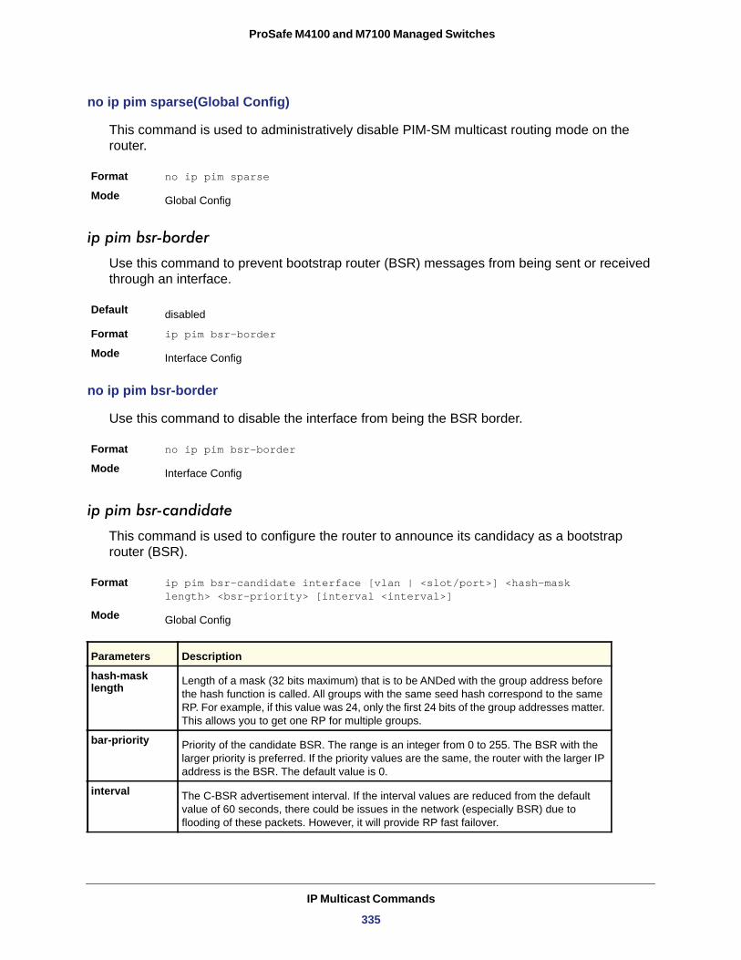
ProSafe M4100 and M7100 Managed Switches
no ip pim sparse(Global Config)
This command is used to administratively disable PIM-SM multicast routing mode on the router.
Format no ip pim sparse
Mode
ip pim bsr-border
Use this command to prevent bootstrap router (BSR) messages from being sent or received through an interface.
Default
Format ip pim bsr-border
Mode
no ip pim bsr-border
Use this command to disable the interface from being the BSR border.
Format no ip pim bsr-border
Mode
ip pim bsr-candidate
This command is used to configure the router to announce its candidacy as a bootstrap router (BSR).
Format ip pim bsr-candidate interface [vlan | <slot/port>] <hash-mask length> <bsr-priority> [interval <interval>]
Mode
hash-mask length
bar-priority
interval
Global Config
disabled
Interface Config
Interface Config
Global Config
Parameters Description
Length of a mask (32 bits maximum) that is to be ANDed with the group address before the hash function is called. All groups with the same seed hash correspond to the same RP. For example, if this value was 24, only the first 24 bits of the group addresses matter. This allows you to get one RP for multiple groups.
Priority of the candidate BSR. The range is an integer from 0 to 255. The BSR with the larger priority is preferred. If the priority values are the same, the router with the larger IP address is the BSR. The default value is 0.
The C-BSR advertisement interval. If the interval values are reduced from the default value of 60 seconds, there could be issues in the network (especially BSR) due to flooding of these packets. However, it will provide RP fast failover.
IP Multicast Commands
335
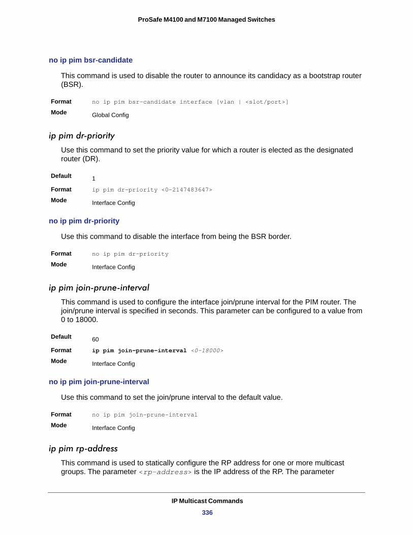
ProSafe M4100 and M7100 Managed Switches
no ip pim bsr-candidate
This command is used to disable the router to announce its candidacy as a bootstrap router (BSR).
Format no ip pim bsr-candidate interface [vlan | <slot/port>]
Mode
ip pim dr-priority
Use this command to set the priority value for which a router is elected as the designated router (DR).
Default
Format ip pim dr-priority <0-2147483647>
Mode
no ip pim dr-priority
Use this command to disable the interface from being the BSR border.
Format no ip pim dr-priority
Mode
ip pim join-prune-interval
This command is used to configure the interface join/prune interval for the PIM router. The join/prune interval is specified in seconds. This parameter can be configured to a value from 0 to 18000.
Default
Format ip pim join-prune-interval <0-18000>
Mode
no ip pim join-prune-interval
Use this command to set the join/prune interval to the default value.
Format no ip pim join-prune-interval
Mode
ip pim rp-address
This command is used to statically configure the RP address for one or more multicast groups. The parameter <rp-address> is the IP address of the RP. The parameter
Global Config
1
Interface Config
Interface Config
60
Interface Config
Interface Config
IP Multicast Commands
336
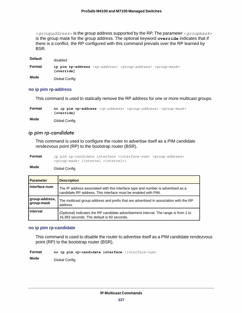
ProSafe M4100 and M7100 Managed Switches
<groupaddress> is the group address supported by the RP. The parameter <groupmask> is the group mask for the group address. The optional keyword override indicates that if there is a conflict, the RP configured with this command prevails over the RP learned by BSR.
Default
Format ip pim rp-address <rp-address> <group-address> <group-mask> [override]
Mode
no ip pim rp-address
This command is used to statically remove the RP address for one or more multicast groups.
Format no ip pim rp-address <rp-address> <group-address> <group-mask> [override]
Mode
ip pim rp-candidate
This command is used to configure the router to advertise itself as a PIM candidate rendezvous point (RP) to the bootstrap router (BSR).
Format ip pim rp-candidate interface <interface-num> <group-address> <group-mask> {interval <interval>}
Mode
interface-num
group-address, group-mask
interval
no ip pim rp-candidate
This command is used to disable the router to advertise itself as a PIM candidate rendezvous point (RP) to the bootstrap router (BSR).
Format no ip pim rp-candidate interface <interface-num>
Mode
disabled
Global Config
Global Config
Global Config
Parameter Description
The IP address associated with this interface type and number is advertised as a candidate RP address. This interface must be enabled with PIM.
The multicast group address and prefix that are advertised in association with the RP address.
(Optional) Indicates the RP candidate advertisement interval. The range is from 1 to 16,383 seconds. The default is 60 seconds.
Global Config
IP Multicast Commands
337
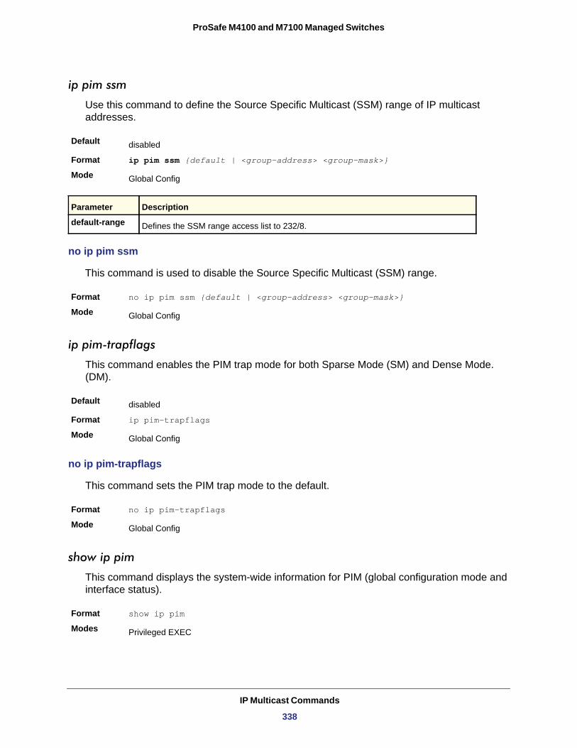
ProSafe M4100 and M7100 Managed Switches
ip pim ssm
Use this command to define the Source Specific Multicast (SSM) range of IP multicast addresses.
Default
Format ip pim ssm {default | <group-address> <group-mask>}
Mode
default-range
no ip pim ssm
This command is used to disable the Source Specific Multicast (SSM) range.
Format no ip pim ssm {default | <group-address> <group-mask>}
Mode
ip pim-trapflags
This command enables the PIM trap mode for both Sparse Mode (SM) and Dense Mode. (DM).
Default
Format ip pim-trapflags
Mode
no ip pim-trapflags
This command sets the PIM trap mode to the default.
Format no ip pim-trapflags
Mode
show ip pim
This command displays the system-wide information for PIM (global configuration mode and interface status).
Format show ip pim
Modes
disabled
Global Config
Parameter Description
Defines the SSM range access list to 232/8.
Global Config
disabled
Global Config
Global Config
Privileged EXEC
IP Multicast Commands
338
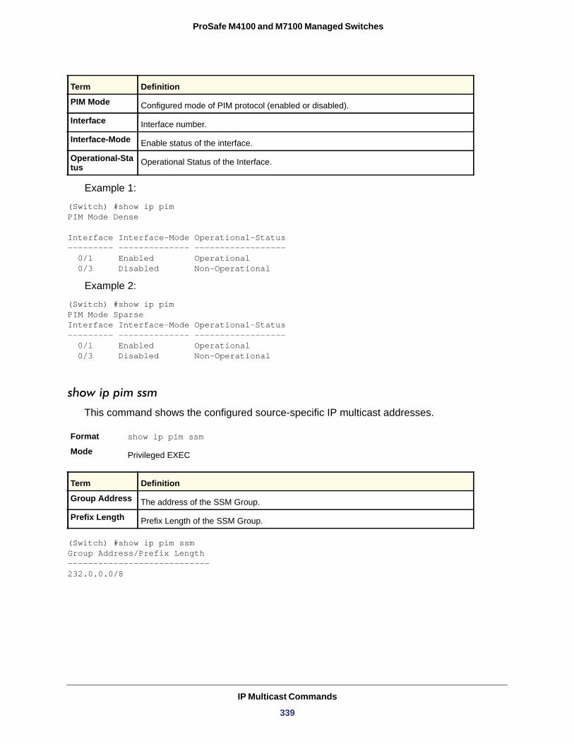
ProSafe M4100 and M7100 Managed Switches
PIM Mode
Interface
Interface-Mode
Operational-Status
Example 1:
(Switch) #show ip pimPIM Mode Dense
Interface Interface-Mode Operational-Status--------- -------------- ------------------ 0/1 Enabled Operational 0/3 Disabled Non-Operational
Example 2:
(Switch) #show ip pimPIM Mode SparseInterface Interface-Mode Operational-Status--------- -------------- ------------------ 0/1 Enabled Operational 0/3 Disabled Non-Operational
show ip pim ssm
This command shows the configured source-specific IP multicast addresses.
Format show ip pim ssm
Mode
Group Address
Prefix Length
(Switch) #show ip pim ssmGroup Address/Prefix Length----------------------------232.0.0.0/8
Term Definition
Configured mode of PIM protocol (enabled or disabled).
Interface number.
Enable status of the interface.
Operational Status of the Interface.
Privileged EXEC
Term Definition
The address of the SSM Group.
Prefix Length of the SSM Group.
IP Multicast Commands
339
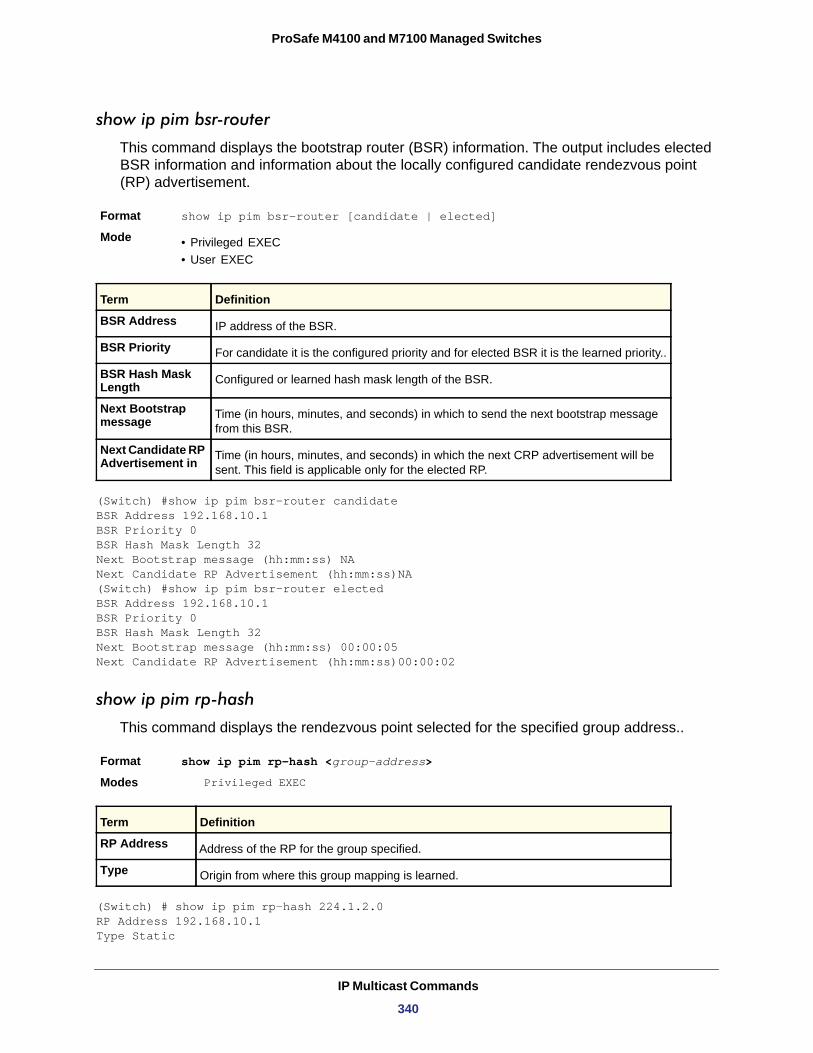
ProSafe M4100 and M7100 Managed Switches
show ip pim bsr-router
This command displays the bootstrap router (BSR) information. The output includes elected BSR information and information about the locally configured candidate rendezvous point (RP) advertisement.
Format show ip pim bsr-router [candidate | elected]
Mode • Privileged EXEC• User EXEC
BSR Address
BSR Priority
BSR Hash Mask Length
Next Bootstrap message
Next Candidate RP Advertisement in
(Switch) #show ip pim bsr-router candidateBSR Address 192.168.10.1BSR Priority 0BSR Hash Mask Length 32Next Bootstrap message (hh:mm:ss) NANext Candidate RP Advertisement (hh:mm:ss)NA(Switch) #show ip pim bsr-router electedBSR Address 192.168.10.1BSR Priority 0BSR Hash Mask Length 32Next Bootstrap message (hh:mm:ss) 00:00:05Next Candidate RP Advertisement (hh:mm:ss)00:00:02
show ip pim rp-hash
This command displays the rendezvous point selected for the specified group address..
Format show ip pim rp-hash <group-address>
Modes Privileged EXEC
RP Address
Type
(Switch) # show ip pim rp-hash 224.1.2.0RP Address 192.168.10.1Type Static
Term Definition
IP address of the BSR.
For candidate it is the configured priority and for elected BSR it is the learned priority..
Configured or learned hash mask length of the BSR.
Time (in hours, minutes, and seconds) in which to send the next bootstrap message from this BSR.
Time (in hours, minutes, and seconds) in which the next CRP advertisement will be sent. This field is applicable only for the elected RP.
Term Definition
Address of the RP for the group specified.
Origin from where this group mapping is learned.
IP Multicast Commands
340
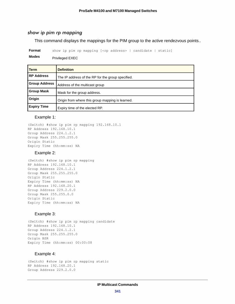
ProSafe M4100 and M7100 Managed Switches
show ip pim rp mapping
This command displays the mappings for the PIM group to the active rendezvous points..
Format show ip pim rp mapping [<rp address> | candidate | static]
Modes
RP Address
Group Address
Group Mask
Origin
Expiry Time
Example 1:
(Switch) #show ip pim rp mapping 192.168.10.1RP Address 192.168.10.1Group Address 224.1.2.1Group Mask 255.255.255.0Origin StaticExpiry Time (hh:mm:ss) NA
Example 2:
(Switch) #show ip pim rp mappingRP Address 192.168.10.1Group Address 224.1.2.1Group Mask 255.255.255.0Origin StaticExpiry Time (hh:mm:ss) NARP Address 192.168.20.1Group Address 229.2.0.0Group Mask 255.255.0.0Origin StaticExpiry Time (hh:mm:ss) NA
Example 3:
(Switch) #show ip pim rp mapping candidateRP Address 192.168.10.1Group Address 224.1.2.1Group Mask 255.255.255.0Origin BSRExpiry Time (hh:mm:ss) 00:00:08
Example 4:
(Switch) #show ip pim rp mapping staticRP Address 192.168.20.1Group Address 229.2.0.0
Privileged EXEC
Term Definition
The IP address of the RP for the group specified.
Address of the multicast group
Mask for the group address.
Origin from where this group mapping is learned.
Expiry time of the elected RP.
IP Multicast Commands
341
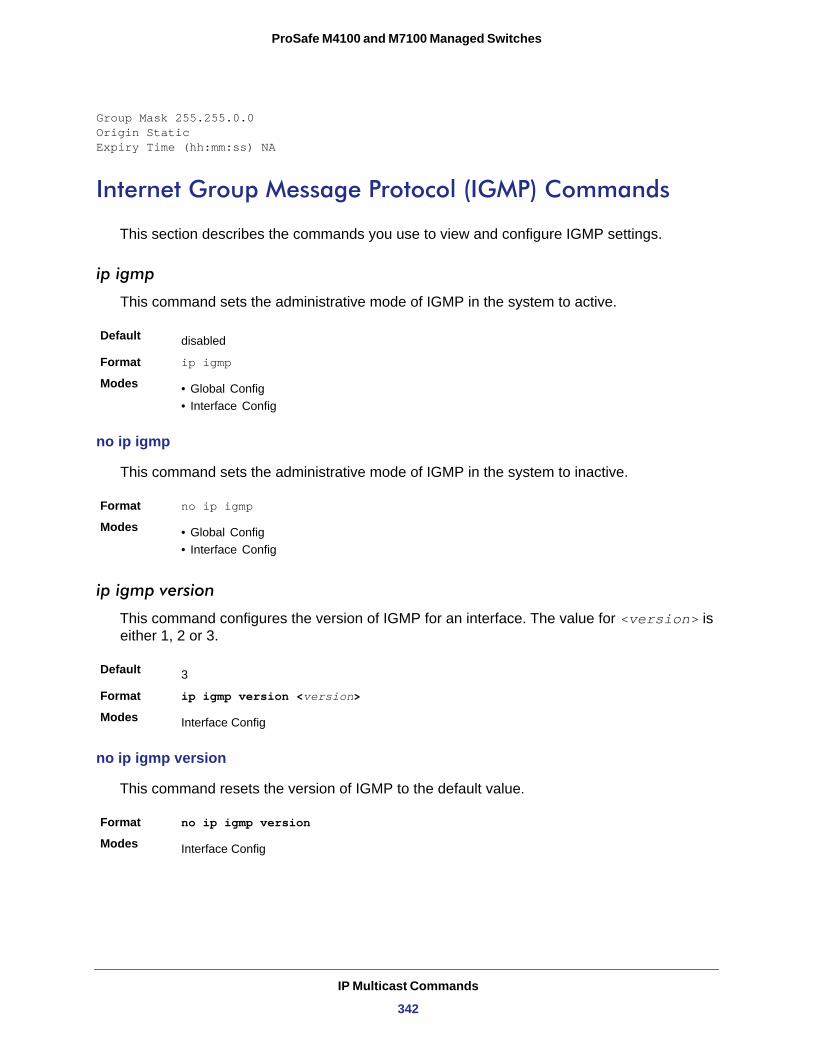
ProSafe M4100 and M7100 Managed Switches
Group Mask 255.255.0.0Origin StaticExpiry Time (hh:mm:ss) NA
Internet Group Message Protocol (IGMP) Commands
This section describes the commands you use to view and configure IGMP settings.
ip igmp
This command sets the administrative mode of IGMP in the system to active.
Default
Format ip igmp
Modes • Global Config• Interface Config
no ip igmp
This command sets the administrative mode of IGMP in the system to inactive.
Format no ip igmp
Modes • Global Config• Interface Config
ip igmp version
This command configures the version of IGMP for an interface. The value for <version> is either 1, 2 or 3.
Default
Format ip igmp version <version>
Modes
no ip igmp version
This command resets the version of IGMP to the default value.
Format no ip igmp version
Modes
disabled
3
Interface Config
Interface Config
IP Multicast Commands
342
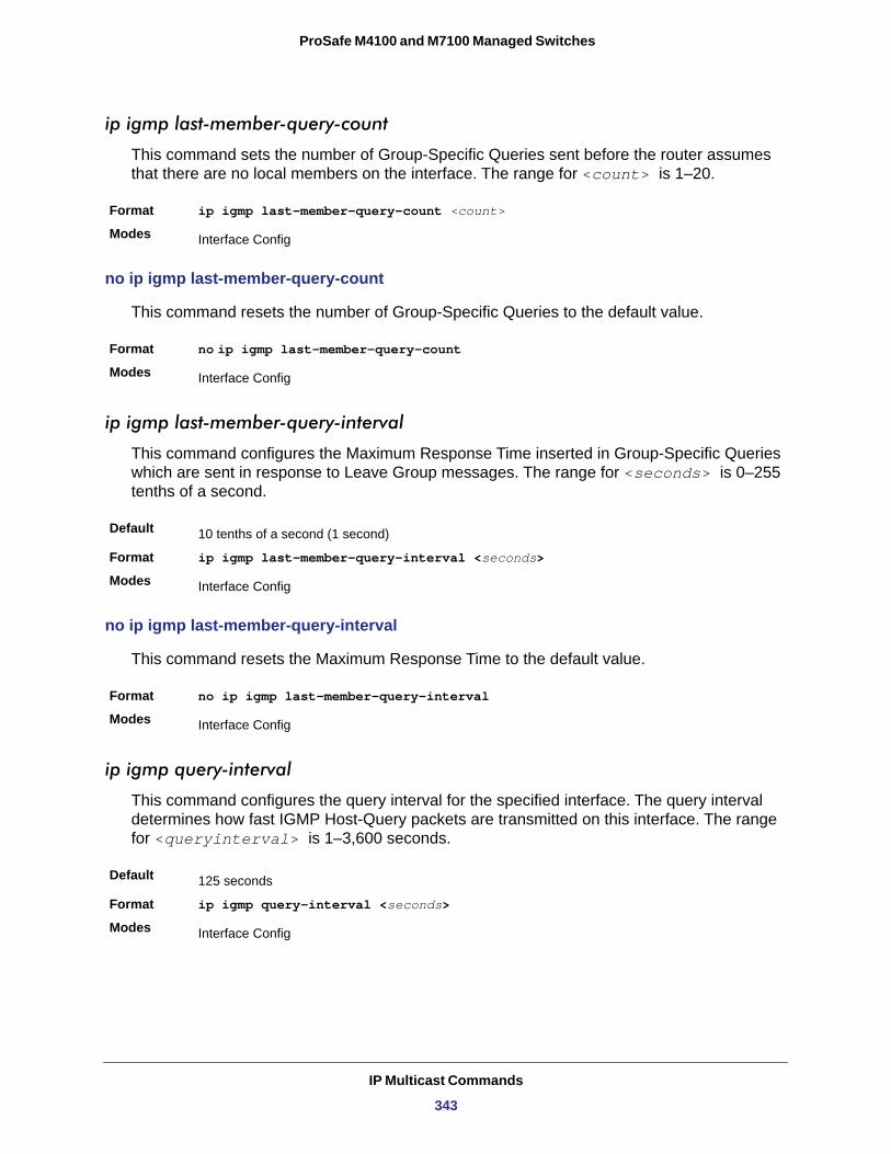
ProSafe M4100 and M7100 Managed Switches
ip igmp last-member-query-count
This command sets the number of Group-Specific Queries sent before the router assumes that there are no local members on the interface. The range for <count> is 1–20.
Format ip igmp last-member-query-count <count>
Modes
no ip igmp last-member-query-count
This command resets the number of Group-Specific Queries to the default value.
Format no ip igmp last-member-query-count
Modes
ip igmp last-member-query-interval
This command configures the Maximum Response Time inserted in Group-Specific Queries which are sent in response to Leave Group messages. The range for <seconds> is 0–255 tenths of a second.
Default
Format ip igmp last-member-query-interval <seconds>
Modes
no ip igmp last-member-query-interval
This command resets the Maximum Response Time to the default value.
Format no ip igmp last-member-query-interval
Modes
ip igmp query-interval
This command configures the query interval for the specified interface. The query interval determines how fast IGMP Host-Query packets are transmitted on this interface. The range for <queryinterval> is 1–3,600 seconds.
Default
Format ip igmp query-interval <seconds>
Modes
Interface Config
Interface Config
10 tenths of a second (1 second)
Interface Config
Interface Config
125 seconds
Interface Config
IP Multicast Commands
343
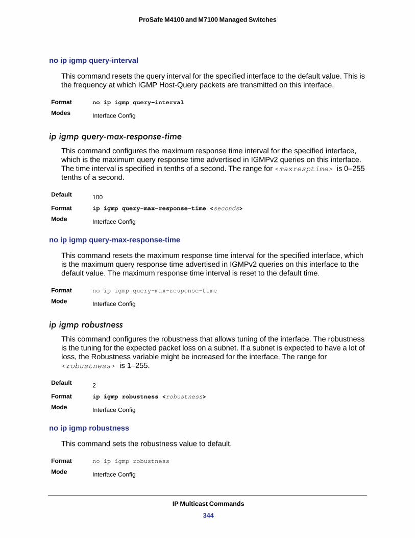
ProSafe M4100 and M7100 Managed Switches
no ip igmp query-interval
This command resets the query interval for the specified interface to the default value. This is the frequency at which IGMP Host-Query packets are transmitted on this interface.
Format no ip igmp query-interval
Modes
ip igmp query-max-response-time
This command configures the maximum response time interval for the specified interface, which is the maximum query response time advertised in IGMPv2 queries on this interface. The time interval is specified in tenths of a second. The range for <maxresptime> is 0–255 tenths of a second.
Default
Format ip igmp query-max-response-time <seconds>
Mode
no ip igmp query-max-response-time
This command resets the maximum response time interval for the specified interface, which is the maximum query response time advertised in IGMPv2 queries on this interface to the default value. The maximum response time interval is reset to the default time.
Format no ip igmp query-max-response-time
Mode
ip igmp robustness
This command configures the robustness that allows tuning of the interface. The robustness is the tuning for the expected packet loss on a subnet. If a subnet is expected to have a lot of loss, the Robustness variable might be increased for the interface. The range for <robustness> is 1–255.
Default
Format ip igmp robustness <robustness>
Mode
no ip igmp robustness
This command sets the robustness value to default.
Format no ip igmp robustness
Mode
Interface Config
100
Interface Config
Interface Config
2
Interface Config
Interface Config
IP Multicast Commands
344
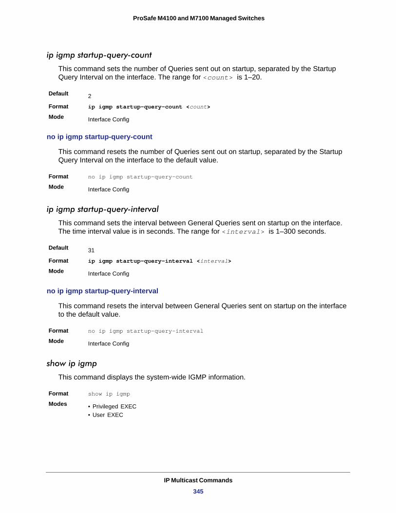
ProSafe M4100 and M7100 Managed Switches
ip igmp startup-query-count
This command sets the number of Queries sent out on startup, separated by the Startup Query Interval on the interface. The range for <count> is 1–20.
Default
Format ip igmp startup-query-count <count>
Mode
no ip igmp startup-query-count
This command resets the number of Queries sent out on startup, separated by the Startup Query Interval on the interface to the default value.
Format no ip igmp startup-query-count
Mode
ip igmp startup-query-interval
This command sets the interval between General Queries sent on startup on the interface. The time interval value is in seconds. The range for <interval> is 1–300 seconds.
Default
Format ip igmp startup-query-interval <interval>
Mode
no ip igmp startup-query-interval
This command resets the interval between General Queries sent on startup on the interface to the default value.
Format no ip igmp startup-query-interval
Mode
show ip igmp
This command displays the system-wide IGMP information.
Format show ip igmp
Modes • Privileged EXEC• User EXEC
2
Interface Config
Interface Config
31
Interface Config
Interface Config
IP Multicast Commands
345
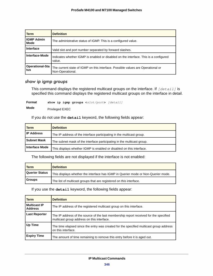
ProSafe M4100 and M7100 Managed Switches
IGMP Admin Mode
Interface
Interface-Mode
Operational-Status
show ip igmp groups
This command displays the registered multicast groups on the interface. If [detail] is specified this command displays the registered multicast groups on the interface in detail.
Format show ip igmp groups <slot/port> [detail]
Mode
If you do not use the detail keyword, the following fields appear:
IP Address
Subnet Mask
Interface Mode
The following fields are not displayed if the interface is not enabled:
Querier Status
Groups
If you use the detail keyword, the following fields appear:
Term Definition
The administrative status of IGMP. This is a configured value.
Valid slot and port number separated by forward slashes.
Indicates whether IGMP is enabled or disabled on the interface. This is a configured value.
The current state of IGMP on this interface. Possible values are Operational or Non-Operational.
Privileged EXEC
Term Definition
The IP address of the interface participating in the multicast group.
The subnet mask of the interface participating in the multicast group.
This displays whether IGMP is enabled or disabled on this interface.
Term Definition
This displays whether the interface has IGMP in Querier mode or Non-Querier mode.
The list of multicast groups that are registered on this interface.
Term Definition
Multicast IP Address The IP address of the registered multicast group on this interface.
Last Reporter The IP address of the source of the last membership report received for the specified multicast group address on this interface.
Up Time The time elapsed since the entry was created for the specified multicast group address on this interface.
Expiry Time The amount of time remaining to remove this entry before it is aged out.
IP Multicast Commands
346
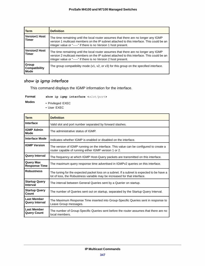
ProSafe M4100 and M7100 Managed Switches
show ip igmp interface
This command displays the IGMP information for the interface.
Format show ip igmp interface <slot/port>
Modes • Privileged EXEC• User EXEC
Interface
IGMP Admin Mode
Interface Mode
IGMP Version
Query Interval
Query Max Response Time
Robustness
Startup Query Interval
Startup Query Count
Last Member Query Interval
Last Member Query Count
Version1 Host Timer The time remaining until the local router assumes that there are no longer any IGMP
version 1 multicast members on the IP subnet attached to this interface. This could be an integer value or “-----” if there is no Version 1 host present.
Version2 Host Timer The time remaining until the local router assumes that there are no longer any IGMP
version 2 multicast members on the IP subnet attached to this interface. This could be an integer value or “-----” if there is no Version 2 host present.
Group Compatibility Mode
The group compatibility mode (v1, v2, or v3) for this group on the specified interface.
Term Definition
Valid slot and port number separated by forward slashes.
The administrative status of IGMP.
Indicates whether IGMP is enabled or disabled on the interface.
The version of IGMP running on the interface. This value can be configured to create a router capable of running either IGMP version 1 or 2.
The frequency at which IGMP Host-Query packets are transmitted on this interface.
The maximum query response time advertised in IGMPv2 queries on this interface.
The tuning for the expected packet loss on a subnet. If a subnet is expected to be have a lot of loss, the Robustness variable may be increased for that interface.
The interval between General Queries sent by a Querier on startup.
The number of Queries sent out on startup, separated by the Startup Query Interval.
The Maximum Response Time inserted into Group-Specific Queries sent in response to Leave Group messages.
The number of Group-Specific Queries sent before the router assumes that there are no local members.
Term Definition
IP Multicast Commands
347
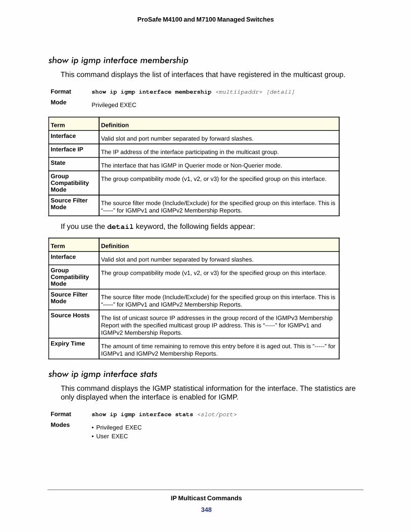
ProSafe M4100 and M7100 Managed Switches
show ip igmp interface membership
This command displays the list of interfaces that have registered in the multicast group.
Format show ip igmp interface membership <multiipaddr> [detail]
Mode
Interface
Interface IP
State
Group Compatibility Mode
Source Filter Mode
If you use the detail keyword, the following fields appear:
Interface
Group Compatibility Mode
Source Filter Mode
Source Hosts
Expiry Time
show ip igmp interface stats
This command displays the IGMP statistical information for the interface. The statistics are only displayed when the interface is enabled for IGMP.
Format show ip igmp interface stats <slot/port>
Modes • Privileged EXEC• User EXEC
Privileged EXEC
Term Definition
Valid slot and port number separated by forward slashes.
The IP address of the interface participating in the multicast group.
The interface that has IGMP in Querier mode or Non-Querier mode.
The group compatibility mode (v1, v2, or v3) for the specified group on this interface.
The source filter mode (Include/Exclude) for the specified group on this interface. This is “-----” for IGMPv1 and IGMPv2 Membership Reports.
Term Definition
Valid slot and port number separated by forward slashes.
The group compatibility mode (v1, v2, or v3) for the specified group on this interface.
The source filter mode (Include/Exclude) for the specified group on this interface. This is “-----” for IGMPv1 and IGMPv2 Membership Reports.
The list of unicast source IP addresses in the group record of the IGMPv3 Membership Report with the specified multicast group IP address. This is “-----” for IGMPv1 and IGMPv2 Membership Reports.
The amount of time remaining to remove this entry before it is aged out. This is “-----” for IGMPv1 and IGMPv2 Membership Reports.
IP Multicast Commands
348
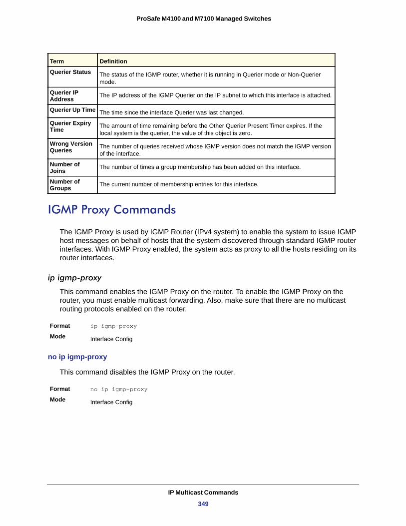
ProSafe M4100 and M7100 Managed Switches
Querier Status
Querier IP Address
Querier Up Time
Querier Expiry Time
Wrong Version Queries
Number of Joins
Number of Groups
IGMP Proxy Commands
The IGMP Proxy is used by IGMP Router (IPv4 system) to enable the system to issue IGMP host messages on behalf of hosts that the system discovered through standard IGMP router interfaces. With IGMP Proxy enabled, the system acts as proxy to all the hosts residing on its router interfaces.
ip igmp-proxy
This command enables the IGMP Proxy on the router. To enable the IGMP Proxy on the router, you must enable multicast forwarding. Also, make sure that there are no multicast routing protocols enabled on the router.
Format ip igmp-proxy
Mode
no ip igmp-proxy
This command disables the IGMP Proxy on the router.
Format no ip igmp-proxy
Mode
Term Definition
The status of the IGMP router, whether it is running in Querier mode or Non-Querier mode.
The IP address of the IGMP Querier on the IP subnet to which this interface is attached.
The time since the interface Querier was last changed.
The amount of time remaining before the Other Querier Present Timer expires. If the local system is the querier, the value of this object is zero.
The number of queries received whose IGMP version does not match the IGMP version of the interface.
The number of times a group membership has been added on this interface.
The current number of membership entries for this interface.
Interface Config
Interface Config
IP Multicast Commands
349
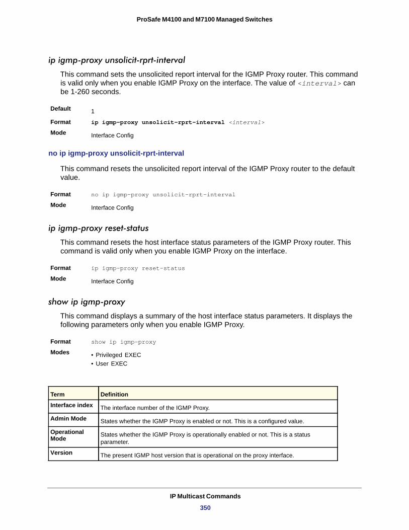
ProSafe M4100 and M7100 Managed Switches
ip igmp-proxy unsolicit-rprt-interval
This command sets the unsolicited report interval for the IGMP Proxy router. This command is valid only when you enable IGMP Proxy on the interface. The value of <interval> can be 1-260 seconds.
Default
Format ip igmp-proxy unsolicit-rprt-interval <interval>
Mode
no ip igmp-proxy unsolicit-rprt-interval
This command resets the unsolicited report interval of the IGMP Proxy router to the default value.
Format no ip igmp-proxy unsolicit-rprt-interval
Mode
ip igmp-proxy reset-status
This command resets the host interface status parameters of the IGMP Proxy router. This command is valid only when you enable IGMP Proxy on the interface.
Format ip igmp-proxy reset-status
Mode
show ip igmp-proxy
This command displays a summary of the host interface status parameters. It displays the following parameters only when you enable IGMP Proxy.
Format show ip igmp-proxy
Modes • Privileged EXEC• User EXEC
1
Interface Config
Interface Config
Interface Config
Term Definition
Interface index The interface number of the IGMP Proxy.
Admin Mode States whether the IGMP Proxy is enabled or not. This is a configured value.
Operational Mode States whether the IGMP Proxy is operationally enabled or not. This is a status
parameter.
Version The present IGMP host version that is operational on the proxy interface.
IP Multicast Commands
350
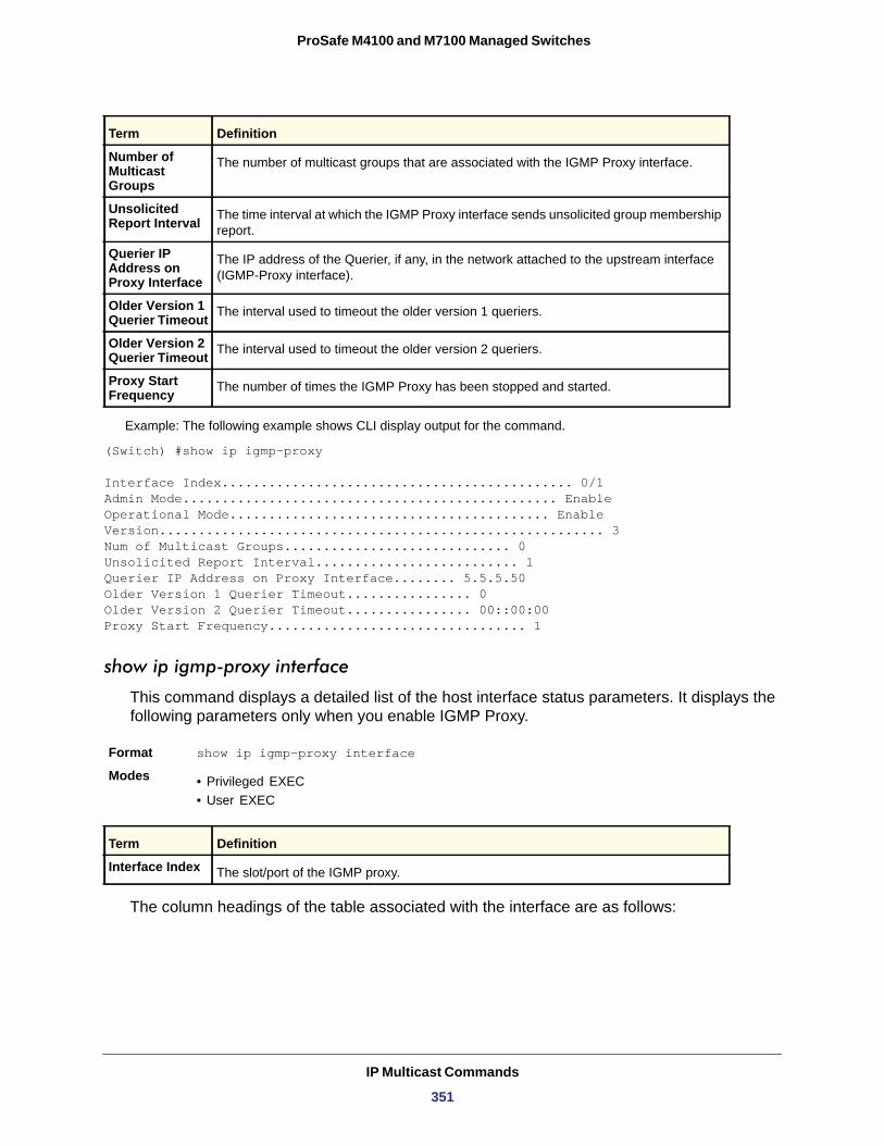
ProSafe M4100 and M7100 Managed Switches
Example: The following example shows CLI display output for the command.
(Switch) #show ip igmp-proxy
Interface Index............................................. 0/1Admin Mode................................................ EnableOperational Mode......................................... EnableVersion......................................................... 3Num of Multicast Groups............................. 0Unsolicited Report Interval.......................... 1Querier IP Address on Proxy Interface........ 5.5.5.50Older Version 1 Querier Timeout................ 0Older Version 2 Querier Timeout................ 00::00:00Proxy Start Frequency................................. 1
show ip igmp-proxy interface
This command displays a detailed list of the host interface status parameters. It displays the following parameters only when you enable IGMP Proxy.
Format show ip igmp-proxy interface
Modes • Privileged EXEC• User EXEC
Interface Index
The column headings of the table associated with the interface are as follows:
Number of Multicast Groups
The number of multicast groups that are associated with the IGMP Proxy interface.
Unsolicited Report Interval The time interval at which the IGMP Proxy interface sends unsolicited group membership
report.
Querier IP Address on Proxy Interface
The IP address of the Querier, if any, in the network attached to the upstream interface (IGMP-Proxy interface).
Older Version 1 Querier Timeout The interval used to timeout the older version 1 queriers.
Older Version 2 Querier Timeout The interval used to timeout the older version 2 queriers.
Proxy Start Frequency The number of times the IGMP Proxy has been stopped and started.
Term Definition
The slot/port of the IGMP proxy.
Term Definition
IP Multicast Commands
351
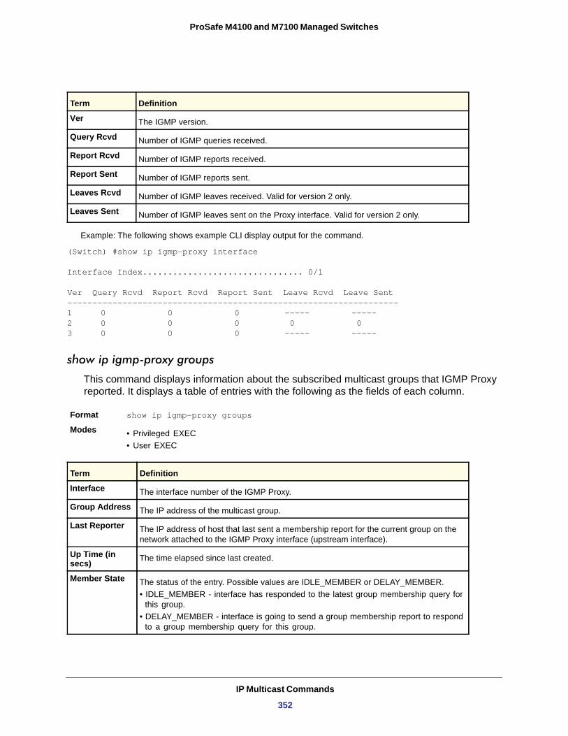
ProSafe M4100 and M7100 Managed Switches
Example: The following shows example CLI display output for the command.
(Switch) #show ip igmp-proxy interface
Interface Index................................ 0/1
Ver Query Rcvd Report Rcvd Report Sent Leave Rcvd Leave Sent------------------------------------------------------------------1 0 0 0 ----- -----2 0 0 0 0 03 0 0 0 ----- -----
show ip igmp-proxy groups
This command displays information about the subscribed multicast groups that IGMP Proxy reported. It displays a table of entries with the following as the fields of each column.
Format show ip igmp-proxy groups
Modes • Privileged EXEC• User EXEC
Term Definition
Ver The IGMP version.
Query Rcvd Number of IGMP queries received.
Report Rcvd Number of IGMP reports received.
Report Sent Number of IGMP reports sent.
Leaves Rcvd Number of IGMP leaves received. Valid for version 2 only.
Leaves Sent Number of IGMP leaves sent on the Proxy interface. Valid for version 2 only.
Term Definition
Interface The interface number of the IGMP Proxy.
Group Address The IP address of the multicast group.
Last Reporter The IP address of host that last sent a membership report for the current group on the network attached to the IGMP Proxy interface (upstream interface).
Up Time (in secs) The time elapsed since last created.
Member State The status of the entry. Possible values are IDLE_MEMBER or DELAY_MEMBER.• IDLE_MEMBER - interface has responded to the latest group membership query for
this group.• DELAY_MEMBER - interface is going to send a group membership report to respond
to a group membership query for this group.
IP Multicast Commands
352
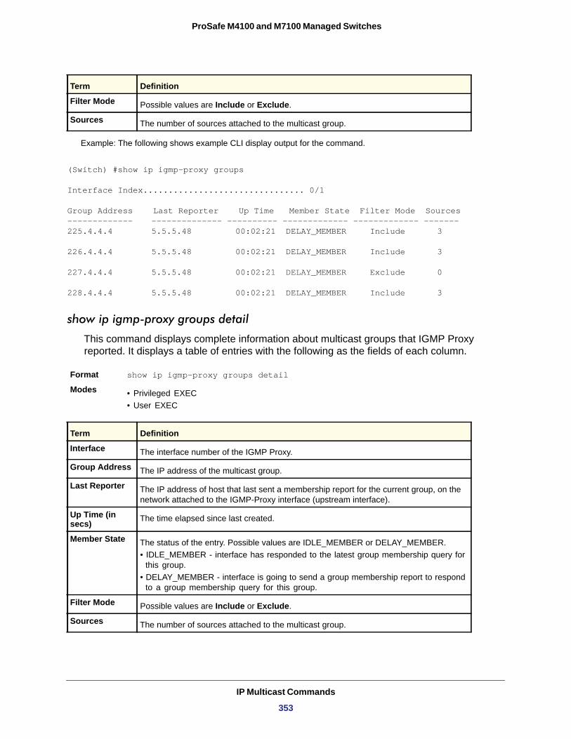
ProSafe M4100 and M7100 Managed Switches
Example: The following shows example CLI display output for the command.
(Switch) #show ip igmp-proxy groups
Interface Index................................ 0/1
Group Address Last Reporter Up Time Member State Filter Mode Sources------------- -------------- ---------- ------------- ------------- -------225.4.4.4 5.5.5.48 00:02:21 DELAY_MEMBER Include 3
226.4.4.4 5.5.5.48 00:02:21 DELAY_MEMBER Include 3
227.4.4.4 5.5.5.48 00:02:21 DELAY_MEMBER Exclude 0
228.4.4.4 5.5.5.48 00:02:21 DELAY_MEMBER Include 3
show ip igmp-proxy groups detail
This command displays complete information about multicast groups that IGMP Proxy reported. It displays a table of entries with the following as the fields of each column.
Format show ip igmp-proxy groups detail
Modes • Privileged EXEC• User EXEC
Filter Mode Possible values are Include or Exclude.
Sources The number of sources attached to the multicast group.
Term Definition
Interface The interface number of the IGMP Proxy.
Group Address The IP address of the multicast group.
Last Reporter The IP address of host that last sent a membership report for the current group, on the network attached to the IGMP-Proxy interface (upstream interface).
Up Time (in secs) The time elapsed since last created.
Member State The status of the entry. Possible values are IDLE_MEMBER or DELAY_MEMBER.• IDLE_MEMBER - interface has responded to the latest group membership query for
this group.• DELAY_MEMBER - interface is going to send a group membership report to respond
to a group membership query for this group.
Filter Mode Possible values are Include or Exclude.
Sources The number of sources attached to the multicast group.
Term Definition
IP Multicast Commands
353
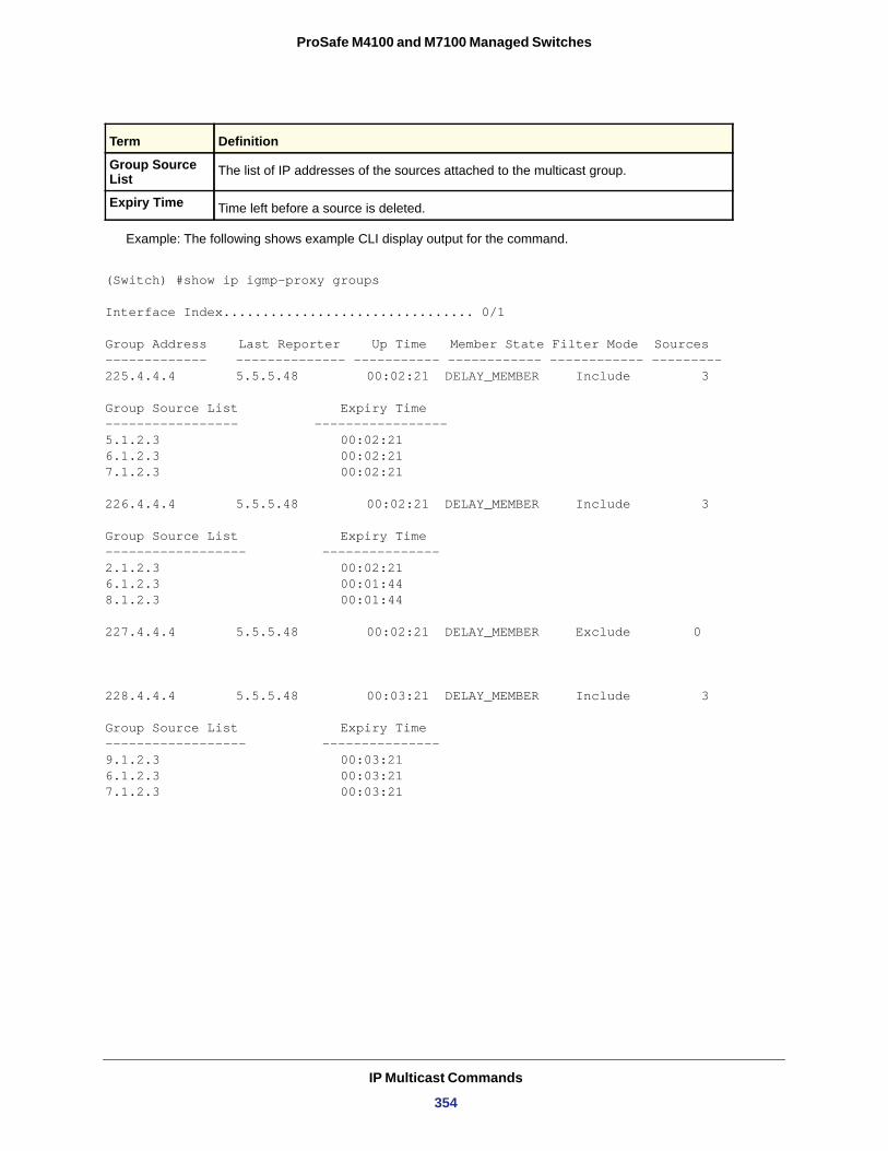
ProSafe M4100 and M7100 Managed Switches
Example: The following shows example CLI display output for the command.
(Switch) #show ip igmp-proxy groups
Interface Index................................ 0/1
Group Address Last Reporter Up Time Member State Filter Mode Sources------------- -------------- ----------- ------------ ------------ --------- 225.4.4.4 5.5.5.48 00:02:21 DELAY_MEMBER Include 3
Group Source List Expiry Time----------------- -----------------5.1.2.3 00:02:21 6.1.2.3 00:02:21 7.1.2.3 00:02:21
226.4.4.4 5.5.5.48 00:02:21 DELAY_MEMBER Include 3
Group Source List Expiry Time------------------ ---------------2.1.2.3 00:02:21 6.1.2.3 00:01:44 8.1.2.3 00:01:44
227.4.4.4 5.5.5.48 00:02:21 DELAY_MEMBER Exclude 0
228.4.4.4 5.5.5.48 00:03:21 DELAY_MEMBER Include 3
Group Source List Expiry Time------------------ ---------------9.1.2.3 00:03:21 6.1.2.3 00:03:21 7.1.2.3 00:03:21
Group Source List The list of IP addresses of the sources attached to the multicast group.
Expiry Time Time left before a source is deleted.
Term Definition
IP Multicast Commands
354
6
6. IPv6 CommandsThis chapter describes the IPv6 commands available in the managed switch CLI.
Note: Some commands described in this chapter require a license. For more information, see Licensing and Command Support on page 8.
This chapter contains the following sections:
• Tunnel Interface Commands • IPv6 Routing Commands • OSPFv3 Commands • OSPFv3 Graceful Restart Commands • DHCPv6 Commands
The commands in this chapter are in three functional groups:
• Show commands display switch settings, statistics, and other information.• Configuration commands configure features and options of the switch. Every switch
command has a show command that displays the configuration setting.• Clear commands clear some or all of the settings to factory defaults.
Note: For information about IPv6 management commands, see IPv6 Management Commands on page 703.
355
ProSafe M4100 and M7100 Managed Switches
Tunnel Interface Commands
The commands in this section describe how to create, delete, and manage tunnel interfaces. Several different types of tunnels provide functionality to facilitate the transition of IPv4 networks to IPv6 networks. These tunnels are divided into two classes: configured and automatic. The distinction is that configured tunnels are explicitly configured with a destination or endpoint of the tunnel. Automatic tunnels, in contrast, infer the endpoint of the tunnel from the destination address of packets routed into the tunnel. To assign an IP address to the tunnel interface, see ip address on page 228. To assign an IPv6 address to the tunnel interface, see ipv6 address on page 359.
interface tunnel
Use this command to enter the Interface Config mode for a tunnel interface. The <tunnel-id> range is 0–7.
Format interface tunnel <tunnel-id>
Mode
no interface tunnel
This command removes the tunnel interface and associated configuration parameters for the specified tunnel interface.
Format no interface tunnel <tunnel-id>
Mode
tunnel source
This command specifies the source transport address of the tunnel, either explicitly or by reference to an interface.
Format tunnel source {<ipv4-address> | ethernet <slot/port>}
Mode
tunnel destination
This command specifies the destination transport address of the tunnel.
Format tunnel destination {<ipv4-address>}
Mode
Global Config
Global Config
Interface Config
Interface Config
IPv6 Commands
356
ProSafe M4100 and M7100 Managed Switches
tunnel mode ipv6ip
This command specifies the mode of the tunnel. With the optional 6to4 argument, the tunnel mode is set to 6to4 automatic. Without the optional 6to4 argument, the tunnel mode is configured.
Format tunnel mode ipv6ip [6to4]
Mode
show interface tunnel
This command displays the parameters related to tunnel such as tunnel mode, tunnel source address, and tunnel destination address.
Format show interface tunnel [<tunnel-id>]
Mode
If you do not specify a tunnel ID, the command shows the following information for each configured tunnel:
Tunnel ID
Interface
Tunnel Mode
Source Address
Destination Address
If you specify a tunnel ID, the command shows the following information for the tunnel:
Interface Link Status
MTU Size
IPv6 Prefix is
IPv6 Routing Commands
This section describes the IPv6 commands you use to configure IPv6 on the system and on the interfaces. This section also describes IPv6 management commands and show commands.
Interface Config
Privileged EXEC
Term Definition
The tunnel identification number.
The name of the tunnel interface.
The tunnel mode.
The source transport address of the tunnel.
The destination transport address of the tunnel.
Term Definition
Shows whether the link is up or down.
The maximum transmission unit for packets on the interface.
If you enable IPv6 on the interface and assign an address, the IPv6 address and prefix display.
IPv6 Commands
357
ProSafe M4100 and M7100 Managed Switches
ipv6 hop-limit
This command defines the unicast hop count used in ipv6 packets originated by the node. The value is also included in router advertisements. Valid values for <hops> are 1-255 inclusive. The default “not configured” means that a value of zero is sent in router advertisements and a value of 64 is sent in packets originated by the node. Note that this is not the same as configuring a value of 64.
Default
Format ipv6 hop-limit <hops>
Mode
no ipv6 hop-limit
This command returns the unicast hop count to the default.
Format no ipv6 hop-limit
Mode
ipv6 unicast-routing
Use this command to enable the forwarding of IPv6 unicast datagrams.
Default
Format ipv6 unicast-routing
Mode
no ipv6 unicast-routing
Use this command to disable the forwarding of IPv6 unicast datagrams.
Format no ipv6 unicast-routing
Mode
ipv6 enable
Use this command to enable IPv6 routing on an interface, including tunnel and loopback interfaces, that has not been configured with an explicit IPv6 address. When you use this command, the interface is automatically configured with a link-local address. You do not need to use this command if you configured an IPv6 global address on the interface.
Default
Format ipv6 enable
Mode
not configured
Global Config
Global Config
disabled
Global Config
Global Config
disabled
Interface Config
IPv6 Commands
358
ProSafe M4100 and M7100 Managed Switches
no ipv6 enable
Use this command to disable IPv6 routing on an interface.
Format no ipv6 enable
Mode
ipv6 address
Use this command to configure an IPv6 address on an interface, including tunnel and loopback interfaces, and to enable IPv6 processing on this interface. You can assign multiple globally reachable addresses to an interface by using this command. You do not need to assign a link-local address by using this command since one is automatically created. The <prefix> field consists of the bits of the address to be configured. The <prefix_length> designates how many of the high-order contiguous bits of the address make up the prefix.
You can express IPv6 addresses in eight blocks. Also of note is that instead of a period, a colon now separates each block. For simplification, leading zeros of each 16-bit block can be omitted. One sequence of 16-bit blocks containing only zeros can be replaced with a double colon “::”, but not more than one at a time (otherwise it is no longer a unique representation).
• Dropping zeros: 3ffe:ffff:100:f101:0:0:0:1 becomes 3ffe:ffff:100:f101::1• Local host: 0000:0000:0000:0000:0000:0000:0000:0001 becomes ::1• Any host: 0000:0000:0000:0000:0000:0000:0000:0000 becomes ::
The hexadecimal letters in the IPv6 addresses are not case-sensitive. An example of an IPv6 prefix and prefix length is 3ffe:1::1234/64.
The optional [eui-64] field designates that IPv6 processing on the interfaces was enabled using an EUI-64 interface ID in the low order 64 bits of the address. If you use this option, the value of <prefix_length> must be 64 bits.
Format ipv6 address <prefix>/<prefix_length> [eui64]Mode
no ipv6 address
Use this command to remove all IPv6 addresses on an interface or specified IPv6 address. The <prefix> parameter consists of the bits of the address to be configured. The <prefix_length> designates how many of the high-order contiguous bits of the address comprise the prefix. The optional [eui-64] field designates that IPv6 processing on the interfaces was enabled using an EUI-64 interface ID in the low order 64 bits of the address.
If you do not supply any parameters, the command deletes all the IPv6 addresses on an interface.
Format no ipv6 address [<prefix>/<prefix_length>] [eui64]Mode
Interface Config
Interface Config
Interface Config
IPv6 Commands
359
ProSafe M4100 and M7100 Managed Switches
ipv6 address autoconfig
This command is used to enable stateless address autoconfiguration capability.
Note: When unicast-routing is enabled, autoconfig mode does not work.
Format ipv6 address autoconfig
Mode
ipv6 address autoconfig
This command disables the stateless autoconfiguration.
Format no ipv6 address autoconfigMode
ipv6 address dhcp
This command is used to enable DHCPv6 client capability.
Format ipv6 address autoconfig
Mode
no pv6 address dhcp
The "no" form of this command disables the DHCPv6 client capability.
Format no ipv6 address autoconfig
Mode
ipv6 route
Use this command to configure an IPv6 static route. The <ipv6-prefix> is the IPv6 network that is the destination of the static route. The <prefix_length> is the length of the IPv6 prefix — a decimal value (usually 0-64) that shows how many of the high-order contiguous bits of the address comprise the prefix (the network portion of the address). A slash mark must precede the <prefix_length>. The <next-hop-address> is the IPv6 address of the next hop that can be used to reach the specified network. Specifying Null0 as nexthop parameter adds a static reject route. The <preference> parameter is a value the router uses to compare this route with routes from other route sources that have the same destination. The range for <preference> is 1 - 255, and the default value is 1. You can specify a <slot/port> or tunnel <tunnel_id> interface to identify direct static routes from point-to-point and broadcast interfaces. The interface must be specified when
Interface Config
Interface Config
Interface Config
Interface Config
IPv6 Commands
360
ProSafe M4100 and M7100 Managed Switches
using a link-local address as the next hop. A route with a preference of 255 cannot be used to forward traffic.
Default
Format ipv6 route <ipv6-prefix>/<prefix_length> {<next-hop-address> | Null0 | interface {<slot/port> | tunnel <tunnel_id>} <next-hop-address>} [<preference>]
Mode
no ipv6 route
Use this command to delete an IPv6 static route. Use the command without the optional parameters to delete all static routes to the specified destination. Use the <preference> parameter to revert the preference of a route to the default preference.
Format no ipv6 route <ipv6-prefix>/<prefix_length> [{<next-hop-address> | Null0 | interface {<slot/port> | tunnel <tunnel_id>} <next-hop-address> | <preference>}]
Mode
ipv6 route distance
This command sets the default distance (preference) for IPv6 static routes. Lower route distance values are preferred when determining the best route. The ipv6 route command allows you to optionally set the distance (preference) of an individual static route. The default distance is used when no distance is specified in this command.
Changing the default distance does not update the distance of existing static routes, even if they were assigned the original default distance. The new default distance will only be applied to static routes created after invoking the ipv6 route distance command.
Default
Format ipv6 route distance <1-255>
Mode
no ipv6 route distance
This command resets the default static route preference value in the router to the original default preference. Lower route preference values are preferred when determining the best route.
Format no ipv6 route distance
Mode
disabled
Global Config
Global Config
1
Global Config
Global Config
IPv6 Commands
361
ProSafe M4100 and M7100 Managed Switches
ipv6 mtu
This command sets the maximum transmission unit (MTU) size, in bytes, of IPv6 packets on an interface. This command replaces the default or link MTU with a new MTU value.
Note: The default MTU value for a tunnel interface is 1480. You cannot change this value.
no ipv6 mtu
This command resets maximum transmission unit value to default value.
Format no ipv6 mtu
Mode
ipv6 nd dad attempts
This command sets the number of duplicate address detection probes transmitted. Duplicate address detection verifies that an IPv6 address on an interface is unique.
Default
Format ipv6 nd dad attempts <0 - 600>
Mode
no ipv6 nd dad attempts
This command resets to number of duplicate address detection value to default value.
Format no ipv6 nd dad attempts
Mode
Default 0 or link speed (MTU value (1500))
Format ipv6 mtu <1280-1500>
Mode Interface Config
Interface Config
1
Interface Config
Interface Config
IPv6 Commands
362
ProSafe M4100 and M7100 Managed Switches
ipv6 nd managed-config-flag
This command sets the “managed address configuration” flag in router advertisements. When the value is true, end nodes use DHCPv6. When the value is false, end nodes automatically configure addresses.
Default
Format ipv6 nd managed-config-flag
Mode
no ipv6 nd managed-config-flag
This command resets the “managed address configuration” flag in router advertisements to the default value.
Format no ipv6 nd managed-config-flag
Mode
ipv6 nd ns-interval
This command sets the interval between router advertisements for advertised neighbor solicitations, in milliseconds. An advertised value of 0 means the interval is unspecified.
Default
Format ipv6 nd ns-interval {<1000-4294967295> | 0}
Mode
no ipv6 nd ns-interval
This command resets the neighbor solicit retransmission interval of the specified interface to the default value.
Format no ipv6 nd ns-interval
Mode
ipv6 nd other-config-flag
This command sets the “other stateful configuration” flag in router advertisements sent from the interface.
Default
Format ipv6 nd other-config-flag
Mode
false
Interface Config
Interface Config
0
Interface Config
Interface Config
false
Interface Config
IPv6 Commands
363
ProSafe M4100 and M7100 Managed Switches
no ipv6 nd other-config-flag
This command resets the “other stateful configuration” flag back to its default value in router advertisements sent from the interface.
Format no ipv6 nd other-config-flag
Mode
ipv6 nd ra-interval
This command sets the transmission interval between router advertisements.
Default
Format ipv6 nd ra-interval-max <4- 1800>
Mode
no ipv6 nd ra-interval
This command sets router advertisement interval to the default.
Format no ipv6 nd ra-interval-max
Mode
ipv6 nd ra-lifetime
This command sets the value, in seconds, that is placed in the Router Lifetime field of the router advertisements sent from the interface. The <lifetime> value must be zero, or it must be an integer between the value of the router advertisement transmission interval and 9000. A value of zero means this router is not to be used as the default router.
Default
Format ipv6 nd ra-lifetime <lifetime>
Mode
no ipv6 nd ra-lifetime
This command resets router lifetime to the default value.
Format no ipv6 nd ra-lifetime
Mode
Interface Config
600
Interface Config
Interface Config
1800
Interface Config
Interface Config
IPv6 Commands
364
ProSafe M4100 and M7100 Managed Switches
ipv6 nd reachable-time
This command sets the router advertisement time to consider a neighbor reachable after neighbor discovery confirmation. Reachable time is specified in milliseconds. A value of zero means the time is unspecified by the router.
Default
Format ipv6 nd reachable-time <0–3600000>
Mode
no ipv6 nd reachable-time
This command means that the reachable time is unspecified for the router.
Format no ipv6 nd reachable-time
Mode
ipv6 nd suppress-ra
This command suppresses router advertisement transmission on an interface.
Default
Format ipv6 nd suppress-ra
Mode
no ipv6 nd suppress-ra
This command enables router transmission on an interface.
Format no ipv6 nd suppress-ra
Mode
ipv6 nd router-preference
This is used to configure router preference value in IPv6 router advertisements on an interface. This will indicate whether to prefer this router over other default routers.
Default Medium
Format ipv6 nd router-preference <high/low/medium>
Mode
0
Interface Config
Interface Config
disabled
Interface Config
Interface Config
Interface Config
IPv6 Commands
365
ProSafe M4100 and M7100 Managed Switches
ipv6 nd router-preference
Format no ipv6 router-preference
Mode
This command will set the router preference to default.
ipv6 unreachables
Use this command to enable the generation of ICMPv6 Destination Unreachable messages. By default, the generation of ICMPv6 Destination Unreachable messages is enabled.
Default
Format ipv6 unreachables
Mode
no ipv6 unreachables
Use this command to prevent the generation of ICMPv6 Destination Unreachable messages.
Format no ipv6 unreachables
Mode
ipv6 icmp error-interval
Use this command to limit the rate at which ICMPv6 error messages are sent. The rate limit is configured as a token bucket, with two configurable parameters, burst-size and burst-interval.
The burst-interval specifies how often the token bucket is initialized with burst-size tokens. burst-interval is from 0 to 2,147,483,647 milliseconds (msec).
The burst-size is the number of ICMPv6 error messages that can be sent during one burst-interval. The range is from 1 to 200 messages.
To disable ICMP rate limiting, set burst-interval to zero (0).
Default • burst-interval of 1000 msec.• burst-size of 100 messages
Format ipv6 icmp error-interval <burst-interval> [<burst-size>]
Mode
Interface Config
enable
Interface Config
Interface Config
Global Config
IPv6 Commands
366
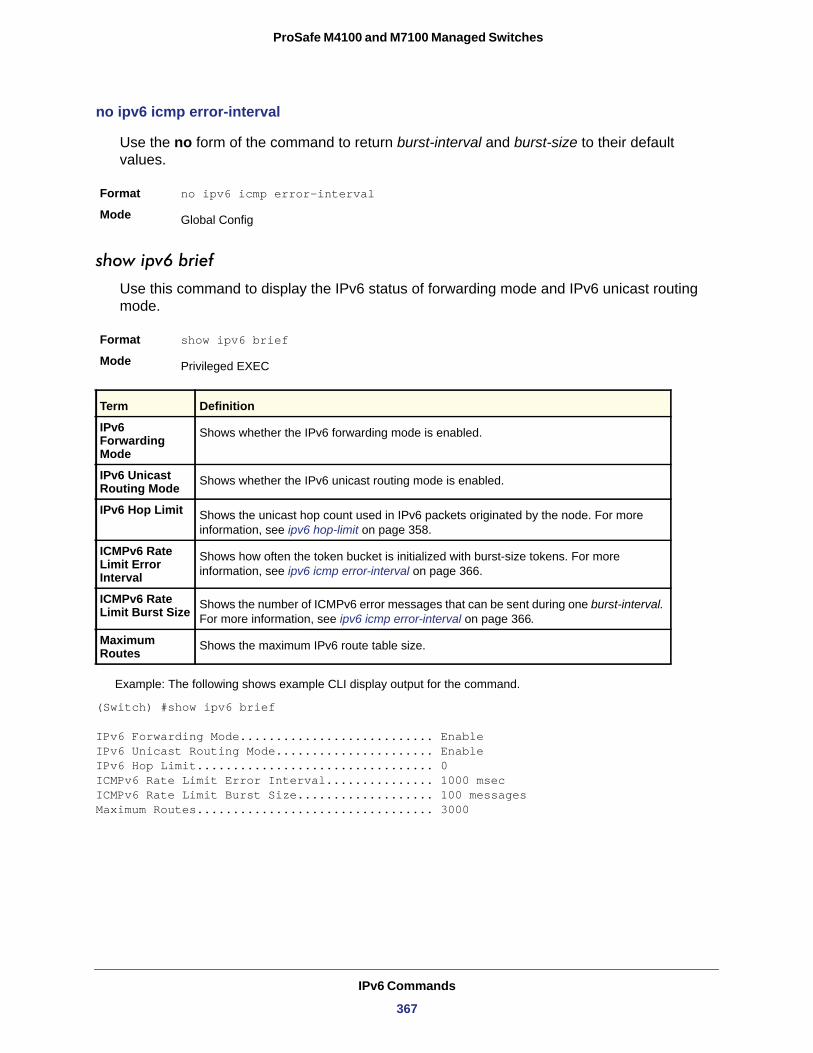
ProSafe M4100 and M7100 Managed Switches
no ipv6 icmp error-interval
Use the no form of the command to return burst-interval and burst-size to their default values.
Format no ipv6 icmp error-interval
Mode
show ipv6 brief
Use this command to display the IPv6 status of forwarding mode and IPv6 unicast routing mode.
Format show ipv6 brief
Mode
IPv6 Forwarding Mode
IPv6 Unicast Routing Mode
IPv6 Hop Limit
ICMPv6 Rate Limit Error Interval
ICMPv6 Rate Limit Burst Size
Maximum Routes
Example: The following shows example CLI display output for the command.
(Switch) #show ipv6 brief
IPv6 Forwarding Mode........................... EnableIPv6 Unicast Routing Mode...................... EnableIPv6 Hop Limit................................. 0ICMPv6 Rate Limit Error Interval............... 1000 msecICMPv6 Rate Limit Burst Size................... 100 messagesMaximum Routes................................. 3000
Global Config
Privileged EXEC
Term Definition
Shows whether the IPv6 forwarding mode is enabled.
Shows whether the IPv6 unicast routing mode is enabled.
Shows the unicast hop count used in IPv6 packets originated by the node. For more information, see ipv6 hop-limit on page 358.
Shows how often the token bucket is initialized with burst-size tokens. For more information, see ipv6 icmp error-interval on page 366.
Shows the number of ICMPv6 error messages that can be sent during one burst-interval. For more information, see ipv6 icmp error-interval on page 366.
Shows the maximum IPv6 route table size.
IPv6 Commands
367
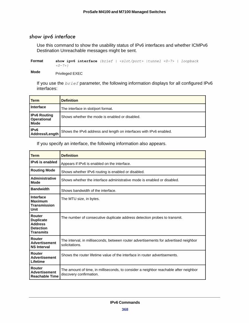
ProSafe M4100 and M7100 Managed Switches
show ipv6 interface
Use this command to show the usability status of IPv6 interfaces and whether ICMPv6 Destination Unreachable messages might be sent.
Format show ipv6 interface {brief | <slot/port> |tunnel <0-7> | loopback <0-7>}
Mode
If you use the brief parameter, the following information displays for all configured IPv6 interfaces:
Interface
IPv6 Routing Operational Mode
IPv6 Address/Length
If you specify an interface, the following information also appears.
Privileged EXEC
Term Definition
The interface in slot/port format.
Shows whether the mode is enabled or disabled.
Shows the IPv6 address and length on interfaces with IPv6 enabled.
Term Definition
IPv6 is enabled Appears if IPv6 is enabled on the interface.
Routing Mode Shows whether IPv6 routing is enabled or disabled.
Administrative Mode Shows whether the interface administrative mode is enabled or disabled.
Bandwidth Shows bandwidth of the interface.
Interface Maximum Transmission Unit
The MTU size, in bytes.
Router Duplicate Address Detection Transmits
The number of consecutive duplicate address detection probes to transmit.
Router Advertisement NS Interval
The interval, in milliseconds, between router advertisements for advertised neighbor solicitations.
Router Advertisement Lifetime
Shows the router lifetime value of the interface in router advertisements.
Router Advertisement Reachable Time
The amount of time, in milliseconds, to consider a neighbor reachable after neighbor discovery confirmation.
IPv6 Commands
368
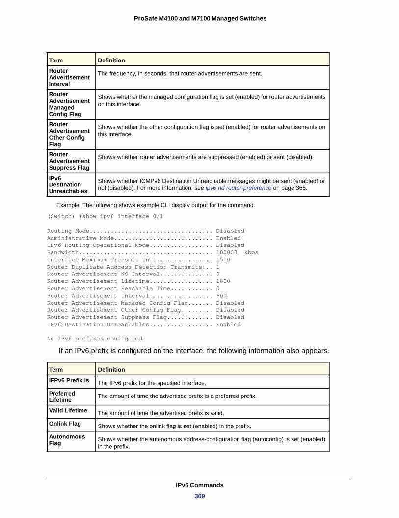
ProSafe M4100 and M7100 Managed Switches
Example: The following shows example CLI display output for the command.
(Switch) #show ipv6 interface 0/1
Routing Mode................................... DisabledAdministrative Mode............................ EnabledIPv6 Routing Operational Mode.................. DisabledBandwidth...................................... 100000 kbpsInterface Maximum Transmit Unit................ 1500Router Duplicate Address Detection Transmits... 1Router Advertisement NS Interval............... 0Router Advertisement Lifetime.................. 1800Router Advertisement Reachable Time............ 0Router Advertisement Interval.................. 600Router Advertisement Managed Config Flag....... DisabledRouter Advertisement Other Config Flag......... DisabledRouter Advertisement Suppress Flag............. DisabledIPv6 Destination Unreachables.................. Enabled
No IPv6 prefixes configured.
If an IPv6 prefix is configured on the interface, the following information also appears.
IFPv6 Prefix is
Preferred Lifetime
Valid Lifetime
Onlink Flag
Autonomous Flag
Router Advertisement Interval
The frequency, in seconds, that router advertisements are sent.
Router Advertisement Managed Config Flag
Shows whether the managed configuration flag is set (enabled) for router advertisements on this interface.
Router Advertisement Other Config Flag
Shows whether the other configuration flag is set (enabled) for router advertisements on this interface.
Router Advertisement Suppress Flag
Shows whether router advertisements are suppressed (enabled) or sent (disabled).
IPv6 Destination Unreachables
Shows whether ICMPv6 Destination Unreachable messages might be sent (enabled) or not (disabled). For more information, see ipv6 nd router-preference on page 365.
Term Definition
The IPv6 prefix for the specified interface.
The amount of time the advertised prefix is a preferred prefix.
The amount of time the advertised prefix is valid.
Shows whether the onlink flag is set (enabled) in the prefix.
Shows whether the autonomous address-configuration flag (autoconfig) is set (enabled) in the prefix.
Term Definition
IPv6 Commands
369
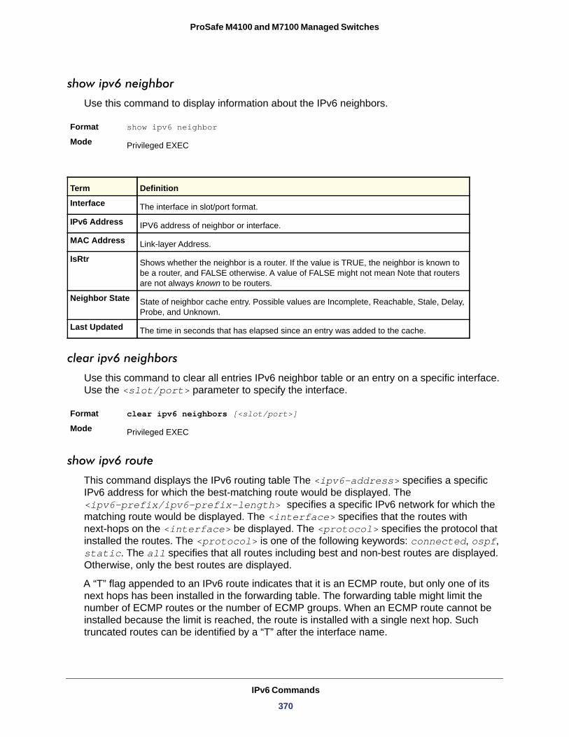
ProSafe M4100 and M7100 Managed Switches
show ipv6 neighbor
Use this command to display information about the IPv6 neighbors.
Format show ipv6 neighbor
Mode
clear ipv6 neighbors
Use this command to clear all entries IPv6 neighbor table or an entry on a specific interface. Use the <slot/port> parameter to specify the interface.
Format clear ipv6 neighbors [<slot/port>]
Mode
show ipv6 route
This command displays the IPv6 routing table The <ipv6-address> specifies a specific IPv6 address for which the best-matching route would be displayed. The <ipv6-prefix/ipv6-prefix-length> specifies a specific IPv6 network for which the matching route would be displayed. The <interface> specifies that the routes with next-hops on the <interface> be displayed. The <protocol> specifies the protocol that installed the routes. The <protocol> is one of the following keywords: connected, ospf, static. The all specifies that all routes including best and non-best routes are displayed. Otherwise, only the best routes are displayed.
A “T” flag appended to an IPv6 route indicates that it is an ECMP route, but only one of its next hops has been installed in the forwarding table. The forwarding table might limit the number of ECMP routes or the number of ECMP groups. When an ECMP route cannot be installed because the limit is reached, the route is installed with a single next hop. Such truncated routes can be identified by a “T” after the interface name.
Privileged EXEC
Term Definition
Interface The interface in slot/port format.
IPv6 Address IPV6 address of neighbor or interface.
MAC Address Link-layer Address.
IsRtr Shows whether the neighbor is a router. If the value is TRUE, the neighbor is known to be a router, and FALSE otherwise. A value of FALSE might not mean Note that routers are not always known to be routers.
Neighbor State State of neighbor cache entry. Possible values are Incomplete, Reachable, Stale, Delay, Probe, and Unknown.
Last Updated The time in seconds that has elapsed since an entry was added to the cache.
Privileged EXEC
IPv6 Commands
370
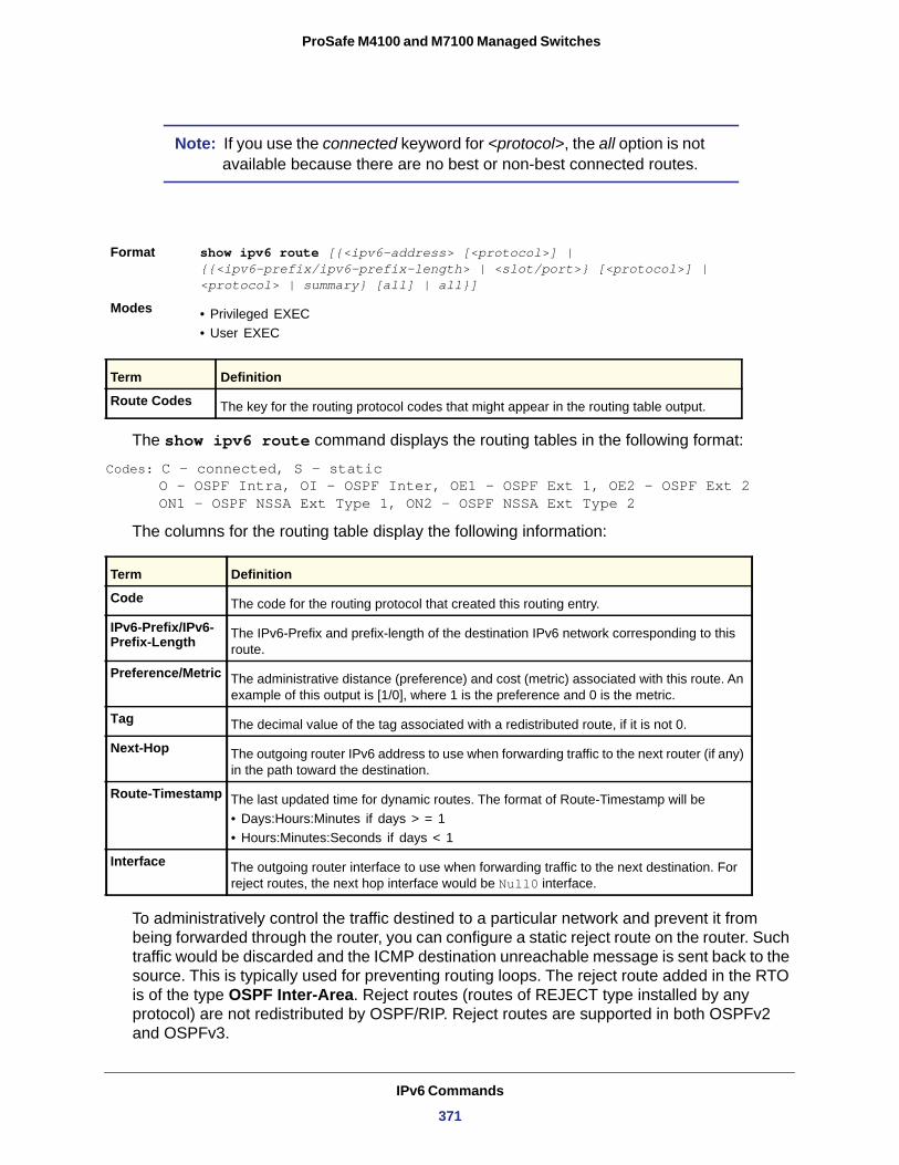
ProSafe M4100 and M7100 Managed Switches
Note: If you use the connected keyword for <protocol>, the all option is not available because there are no best or non-best connected routes.
The show ipv6 route command displays the routing tables in the following format:
Codes: C - connected, S - staticO - OSPF Intra, OI - OSPF Inter, OE1 - OSPF Ext 1, OE2 - OSPF Ext 2ON1 - OSPF NSSA Ext Type 1, ON2 - OSPF NSSA Ext Type 2
The columns for the routing table display the following information:
Code
IPv6-Prefix/IPv6-Prefix-Length
Preference/Metric
Tag
Next-Hop
Route-Timestamp
• Days:Hours:Minutes if days > = 1• Hours:Minutes:Seconds if days < 1
Interface
To administratively control the traffic destined to a particular network and prevent it from being forwarded through the router, you can configure a static reject route on the router. Such traffic would be discarded and the ICMP destination unreachable message is sent back to the source. This is typically used for preventing routing loops. The reject route added in the RTO is of the type OSPF Inter-Area. Reject routes (routes of REJECT type installed by any protocol) are not redistributed by OSPF/RIP. Reject routes are supported in both OSPFv2 and OSPFv3.
Format show ipv6 route [{<ipv6-address> [<protocol>] | {{<ipv6-prefix/ipv6-prefix-length> | <slot/port>} [<protocol>] | <protocol> | summary} [all] | all}]
Modes • Privileged EXEC• User EXEC
Term Definition
Route Codes The key for the routing protocol codes that might appear in the routing table output.
Term Definition
The code for the routing protocol that created this routing entry.
The IPv6-Prefix and prefix-length of the destination IPv6 network corresponding to this route.
The administrative distance (preference) and cost (metric) associated with this route. An example of this output is [1/0], where 1 is the preference and 0 is the metric.
The decimal value of the tag associated with a redistributed route, if it is not 0.
The outgoing router IPv6 address to use when forwarding traffic to the next router (if any) in the path toward the destination.
The last updated time for dynamic routes. The format of Route-Timestamp will be
The outgoing router interface to use when forwarding traffic to the next destination. For reject routes, the next hop interface would be Null0 interface.
IPv6 Commands
371
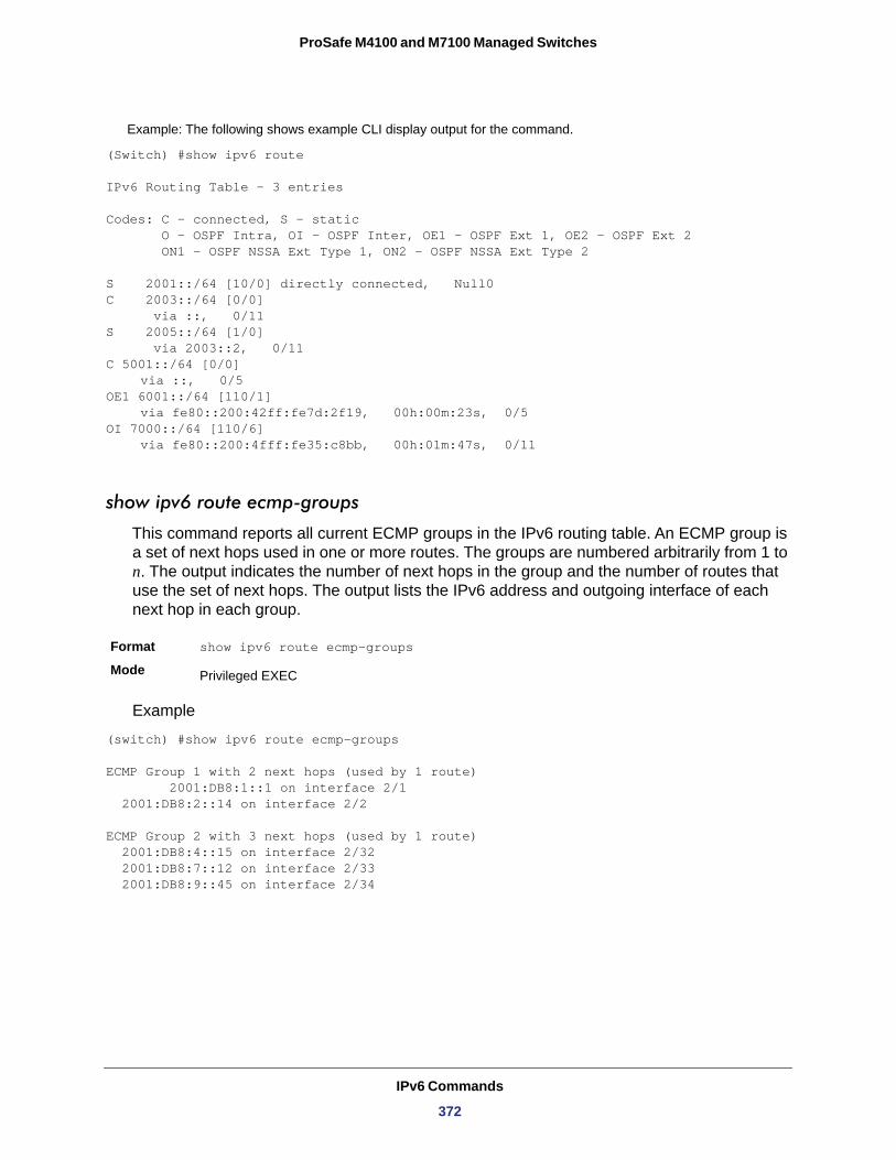
ProSafe M4100 and M7100 Managed Switches
Example: The following shows example CLI display output for the command.
(Switch) #show ipv6 route
IPv6 Routing Table - 3 entries
Codes: C - connected, S - static O - OSPF Intra, OI - OSPF Inter, OE1 - OSPF Ext 1, OE2 - OSPF Ext 2 ON1 - OSPF NSSA Ext Type 1, ON2 - OSPF NSSA Ext Type 2
S 2001::/64 [10/0] directly connected, Null0C 2003::/64 [0/0] via ::, 0/11S 2005::/64 [1/0] via 2003::2, 0/11C 5001::/64 [0/0]
via ::, 0/5OE1 6001::/64 [110/1] via fe80::200:42ff:fe7d:2f19, 00h:00m:23s, 0/5OI 7000::/64 [110/6]
via fe80::200:4fff:fe35:c8bb, 00h:01m:47s, 0/11
show ipv6 route ecmp-groups
This command reports all current ECMP groups in the IPv6 routing table. An ECMP group is a set of next hops used in one or more routes. The groups are numbered arbitrarily from 1 to n. The output indicates the number of next hops in the group and the number of routes that use the set of next hops. The output lists the IPv6 address and outgoing interface of each next hop in each group.
Format show ipv6 route ecmp-groups
Mode
Example
(switch) #show ipv6 route ecmp-groups
ECMP Group 1 with 2 next hops (used by 1 route) 2001:DB8:1::1 on interface 2/1 2001:DB8:2::14 on interface 2/2
ECMP Group 2 with 3 next hops (used by 1 route) 2001:DB8:4::15 on interface 2/32 2001:DB8:7::12 on interface 2/33 2001:DB8:9::45 on interface 2/34
Privileged EXEC
IPv6 Commands
372
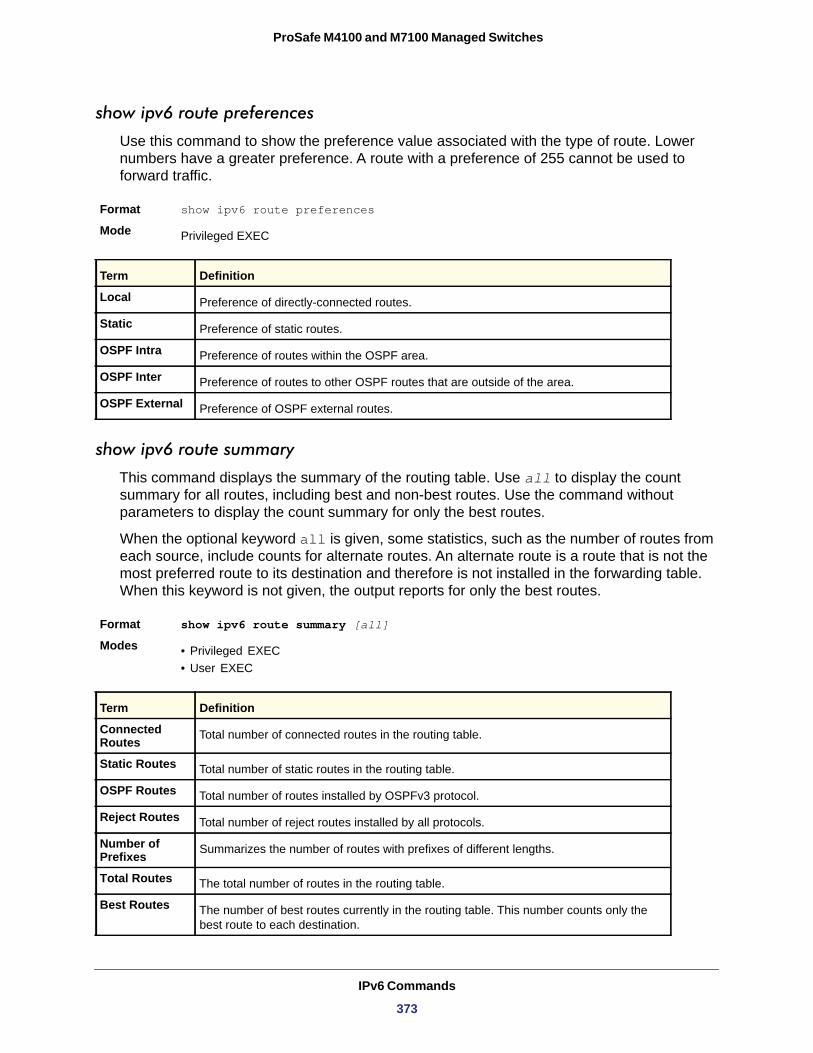
ProSafe M4100 and M7100 Managed Switches
show ipv6 route preferences
Use this command to show the preference value associated with the type of route. Lower numbers have a greater preference. A route with a preference of 255 cannot be used to forward traffic.
Format show ipv6 route preferences
Mode
Local
Static
OSPF Intra
OSPF Inter
OSPF External
show ipv6 route summary
This command displays the summary of the routing table. Use all to display the count summary for all routes, including best and non-best routes. Use the command without parameters to display the count summary for only the best routes.
When the optional keyword all is given, some statistics, such as the number of routes from each source, include counts for alternate routes. An alternate route is a route that is not the most preferred route to its destination and therefore is not installed in the forwarding table. When this keyword is not given, the output reports for only the best routes.
Format show ipv6 route summary [all]
Modes • Privileged EXEC• User EXEC
Privileged EXEC
Term Definition
Preference of directly-connected routes.
Preference of static routes.
Preference of routes within the OSPF area.
Preference of routes to other OSPF routes that are outside of the area.
Preference of OSPF external routes.
Term Definition
Connected Routes Total number of connected routes in the routing table.
Static Routes Total number of static routes in the routing table.
OSPF Routes Total number of routes installed by OSPFv3 protocol.
Reject Routes Total number of reject routes installed by all protocols.
Number of Prefixes Summarizes the number of routes with prefixes of different lengths.
Total Routes The total number of routes in the routing table.
Best Routes The number of best routes currently in the routing table. This number counts only the best route to each destination.
IPv6 Commands
373
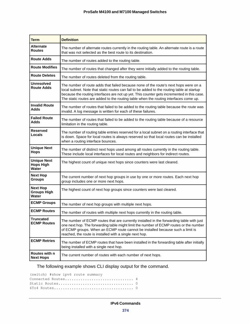
ProSafe M4100 and M7100 Managed Switches
The following example shows CLI display output for the command.
(switch) #show ipv6 route summaryConnected Routes............................... 4Static Routes.................................. 06To4 Routes.................................... 0
Alternate Routes The number of alternate routes currently in the routing table. An alternate route is a route
that was not selected as the best route to its destination.
Route Adds The number of routes added to the routing table.
Route Modifies The number of routes that changed after they were initially added to the routing table.
Route Deletes The number of routes deleted from the routing table.
Unresolved Route Adds The number of route adds that failed because none of the route's next hops were on a
local subnet. Note that static routes can fail to be added to the routing table at startup because the routing interfaces are not up yet. This counter gets incremented in this case. The static routes are added to the routing table when the routing interfaces come up.
Invalid Route Adds The number of routes that failed to be added to the routing table because the route was
invalid. A log message is written for each of these failures.
Failed Route Adds The number of routes that failed to be added to the routing table because of a resource
limitation in the routing table.
Reserved Locals The number of routing table entries reserved for a local subnet on a routing interface that
is down. Space for local routes is always reserved so that local routes can be installed when a routing interface bounces.
Unique Next Hops The number of distinct next hops used among all routes currently in the routing table.
These include local interfaces for local routes and neighbors for indirect routes.
Unique Next Hops High Water
The highest count of unique next hops since counters were last cleared.
Next Hop Groups The current number of next hop groups in use by one or more routes. Each next hop
group includes one or more next hops.
Next Hop Groups High Water
The highest count of next hop groups since counters were last cleared.
ECMP Groups The number of next hop groups with multiple next hops.
ECMP Routes The number of routes with multiple next hops currently in the routing table.
Truncated ECMP Routes The number of ECMP routes that are currently installed in the forwarding table with just
one next hop. The forwarding table might limit the number of ECMP routes or the number of ECMP groups. When an ECMP route cannot be installed because such a limit is reached, the route is installed with a single next hop.
ECMP Retries The number of ECMP routes that have been installed in the forwarding table after initially being installed with a single next hop.
Routes with n Next Hops The current number of routes with each number of next hops.
Term Definition
IPv6 Commands
374
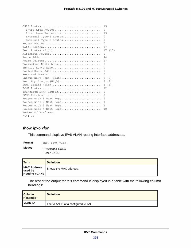
ProSafe M4100 and M7100 Managed Switches
OSPF Routes.................................... 13 Intra Area Routes............................ 0 Inter Area Routes............................ 13 External Type-1 Routes....................... 0 External Type-2 Routes....................... 0Reject Routes.................................. 0Total routes................................... 17Best Routes (High)............................. 17 (17)Alternate Routes............................... 0Route Adds..................................... 44Route Deletes.................................. 27Unresolved Route Adds.......................... 0Invalid Route Adds............................. 0Failed Route Adds.............................. 0Reserved Locals................................ 0Unique Next Hops (High)........................ 8 (8)Next Hop Groups (High)......................... 8 (8)ECMP Groups (High)............................. 3 (3)ECMP Routes.................................... 12Truncated ECMP Routes.......................... 0ECMP Retries................................... 0Routes with 1 Next Hop......................... 5Routes with 2 Next Hops........................ 1Routes with 3 Next Hops........................ 1Routes with 4 Next Hops........................ 10Number of Prefixes:/64: 17
show ipv6 vlan
This command displays IPv6 VLAN routing interface addresses.
Format show ipv6 vlan
Modes • Privileged EXEC• User EXEC
MAC Address used by Routing VLANs
The rest of the output for this command is displayed in a table with the following column headings:
Term Definition
Shows the MAC address.
Column Headings
Definition
VLAN ID The VLAN ID of a configured VLAN.
IPv6 Commands
375
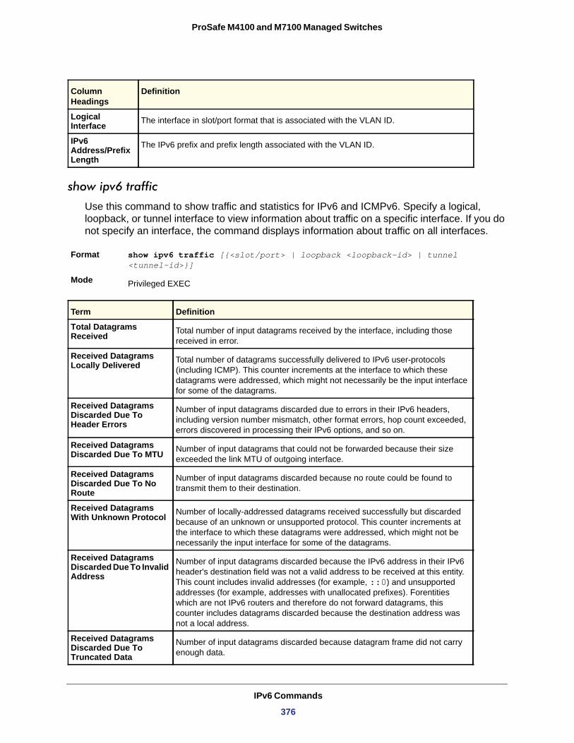
ProSafe M4100 and M7100 Managed Switches
show ipv6 traffic
Use this command to show traffic and statistics for IPv6 and ICMPv6. Specify a logical, loopback, or tunnel interface to view information about traffic on a specific interface. If you do not specify an interface, the command displays information about traffic on all interfaces.
Format show ipv6 traffic [{<slot/port> | loopback <loopback-id> | tunnel <tunnel-id>}]
Mode
Logical Interface The interface in slot/port format that is associated with the VLAN ID.
IPv6 Address/Prefix Length
The IPv6 prefix and prefix length associated with the VLAN ID.
Privileged EXEC
Term Definition
Total Datagrams Received Total number of input datagrams received by the interface, including those
received in error.
Received Datagrams Locally Delivered Total number of datagrams successfully delivered to IPv6 user-protocols
(including ICMP). This counter increments at the interface to which these datagrams were addressed, which might not necessarily be the input interface for some of the datagrams.
Received Datagrams Discarded Due To Header Errors
Number of input datagrams discarded due to errors in their IPv6 headers, including version number mismatch, other format errors, hop count exceeded, errors discovered in processing their IPv6 options, and so on.
Received Datagrams Discarded Due To MTU Number of input datagrams that could not be forwarded because their size
exceeded the link MTU of outgoing interface.
Received Datagrams Discarded Due To No Route
Number of input datagrams discarded because no route could be found to transmit them to their destination.
Received Datagrams With Unknown Protocol Number of locally-addressed datagrams received successfully but discarded
because of an unknown or unsupported protocol. This counter increments at the interface to which these datagrams were addressed, which might not be necessarily the input interface for some of the datagrams.
Received Datagrams Discarded Due To Invalid Address
Number of input datagrams discarded because the IPv6 address in their IPv6 header's destination field was not a valid address to be received at this entity. This count includes invalid addresses (for example, ::0) and unsupported addresses (for example, addresses with unallocated prefixes). Forentities which are not IPv6 routers and therefore do not forward datagrams, this counter includes datagrams discarded because the destination address was not a local address.
Received Datagrams Discarded Due To Truncated Data
Number of input datagrams discarded because datagram frame did not carry enough data.
Column Headings
Definition
IPv6 Commands
376
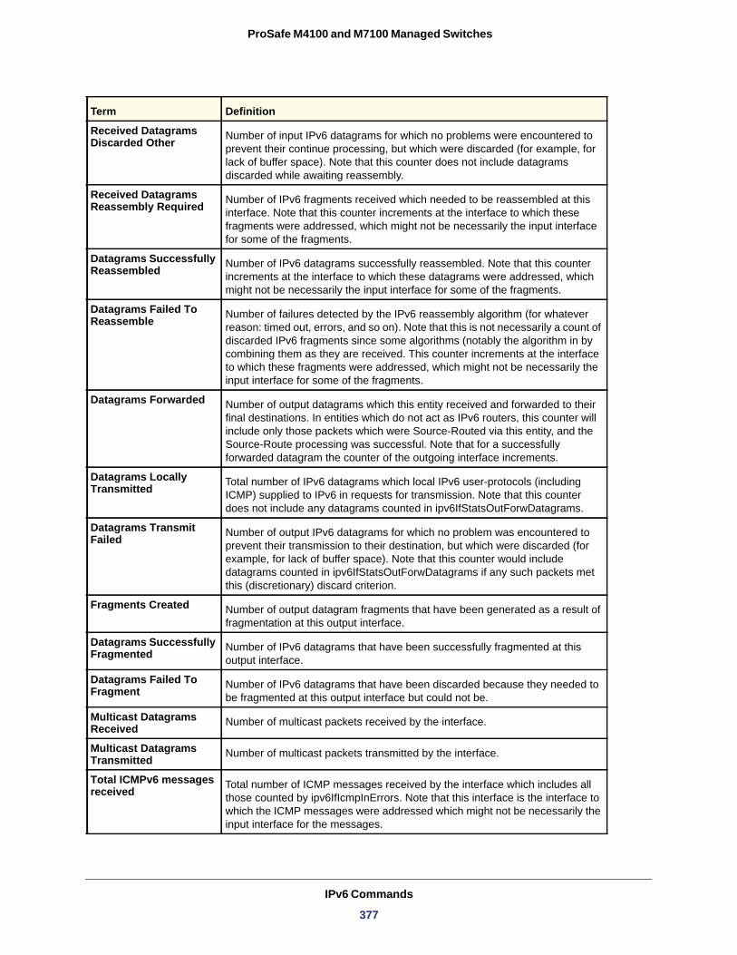
ProSafe M4100 and M7100 Managed Switches
Received Datagrams Discarded Other Number of input IPv6 datagrams for which no problems were encountered to
prevent their continue processing, but which were discarded (for example, for lack of buffer space). Note that this counter does not include datagrams discarded while awaiting reassembly.
Received Datagrams Reassembly Required Number of IPv6 fragments received which needed to be reassembled at this
interface. Note that this counter increments at the interface to which these fragments were addressed, which might not be necessarily the input interface for some of the fragments.
Datagrams Successfully Reassembled Number of IPv6 datagrams successfully reassembled. Note that this counter
increments at the interface to which these datagrams were addressed, which might not be necessarily the input interface for some of the fragments.
Datagrams Failed To Reassemble Number of failures detected by the IPv6 reassembly algorithm (for whatever
reason: timed out, errors, and so on). Note that this is not necessarily a count of discarded IPv6 fragments since some algorithms (notably the algorithm in by combining them as they are received. This counter increments at the interface to which these fragments were addressed, which might not be necessarily the input interface for some of the fragments.
Datagrams Forwarded Number of output datagrams which this entity received and forwarded to their final destinations. In entities which do not act as IPv6 routers, this counter will include only those packets which were Source-Routed via this entity, and the Source-Route processing was successful. Note that for a successfully forwarded datagram the counter of the outgoing interface increments.
Datagrams Locally Transmitted Total number of IPv6 datagrams which local IPv6 user-protocols (including
ICMP) supplied to IPv6 in requests for transmission. Note that this counter does not include any datagrams counted in ipv6IfStatsOutForwDatagrams.
Datagrams Transmit Failed Number of output IPv6 datagrams for which no problem was encountered to
prevent their transmission to their destination, but which were discarded (for example, for lack of buffer space). Note that this counter would include datagrams counted in ipv6IfStatsOutForwDatagrams if any such packets met this (discretionary) discard criterion.
Fragments Created Number of output datagram fragments that have been generated as a result of fragmentation at this output interface.
Datagrams Successfully Fragmented Number of IPv6 datagrams that have been successfully fragmented at this
output interface.
Datagrams Failed To Fragment Number of IPv6 datagrams that have been discarded because they needed to
be fragmented at this output interface but could not be.
Multicast Datagrams Received Number of multicast packets received by the interface.
Multicast Datagrams Transmitted Number of multicast packets transmitted by the interface.
Total ICMPv6 messages received Total number of ICMP messages received by the interface which includes all
those counted by ipv6IfIcmpInErrors. Note that this interface is the interface to which the ICMP messages were addressed which might not be necessarily the input interface for the messages.
Term Definition
IPv6 Commands
377
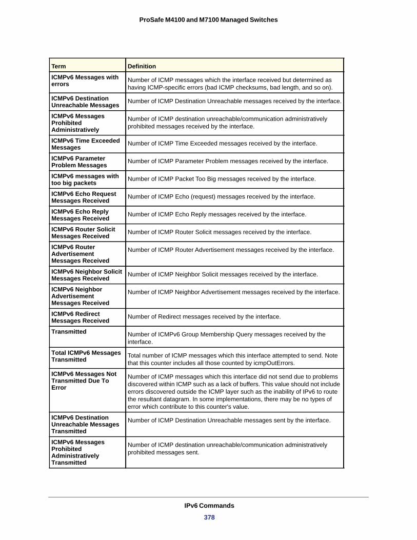
ProSafe M4100 and M7100 Managed Switches
ICMPv6 Messages with errors Number of ICMP messages which the interface received but determined as
having ICMP-specific errors (bad ICMP checksums, bad length, and so on).
ICMPv6 Destination Unreachable Messages Number of ICMP Destination Unreachable messages received by the interface.
ICMPv6 Messages Prohibited Administratively
Number of ICMP destination unreachable/communication administratively prohibited messages received by the interface.
ICMPv6 Time Exceeded Messages Number of ICMP Time Exceeded messages received by the interface.
ICMPv6 Parameter Problem Messages Number of ICMP Parameter Problem messages received by the interface.
ICMPv6 messages with too big packets Number of ICMP Packet Too Big messages received by the interface.
ICMPv6 Echo Request Messages Received Number of ICMP Echo (request) messages received by the interface.
ICMPv6 Echo Reply Messages Received Number of ICMP Echo Reply messages received by the interface.
ICMPv6 Router Solicit Messages Received Number of ICMP Router Solicit messages received by the interface.
ICMPv6 Router Advertisement Messages Received
Number of ICMP Router Advertisement messages received by the interface.
ICMPv6 Neighbor Solicit Messages Received Number of ICMP Neighbor Solicit messages received by the interface.
ICMPv6 Neighbor Advertisement Messages Received
Number of ICMP Neighbor Advertisement messages received by the interface.
ICMPv6 Redirect Messages Received Number of Redirect messages received by the interface.
Transmitted Number of ICMPv6 Group Membership Query messages received by the interface.
Total ICMPv6 Messages Transmitted Total number of ICMP messages which this interface attempted to send. Note
that this counter includes all those counted by icmpOutErrors.
ICMPv6 Messages Not Transmitted Due To Error
Number of ICMP messages which this interface did not send due to problems discovered within ICMP such as a lack of buffers. This value should not include errors discovered outside the ICMP layer such as the inability of IPv6 to route the resultant datagram. In some implementations, there may be no types of error which contribute to this counter's value.
ICMPv6 Destination Unreachable Messages Transmitted
Number of ICMP Destination Unreachable messages sent by the interface.
ICMPv6 Messages Prohibited Administratively Transmitted
Number of ICMP destination unreachable/communication administratively prohibited messages sent.
Term Definition
IPv6 Commands
378
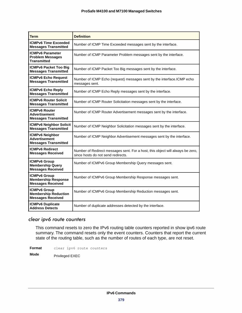
ProSafe M4100 and M7100 Managed Switches
clear ipv6 route counters
This command resets to zero the IPv6 routing table counters reported in show ipv6 route summary. The command resets only the event counters. Counters that report the current state of the routing table, such as the number of routes of each type, are not reset.
Format clear ipv6 route counters
Mode
ICMPv6 Time Exceeded Messages Transmitted Number of ICMP Time Exceeded messages sent by the interface.
ICMPv6 Parameter Problem Messages Transmitted
Number of ICMP Parameter Problem messages sent by the interface.
ICMPv6 Packet Too Big Messages Transmitted Number of ICMP Packet Too Big messages sent by the interface.
ICMPv6 Echo Request Messages Transmitted Number of ICMP Echo (request) messages sent by the interface.ICMP echo
messages sent.
ICMPv6 Echo Reply Messages Transmitted Number of ICMP Echo Reply messages sent by the interface.
ICMPv6 Router Solicit Messages Transmitted Number of ICMP Router Solicitation messages sent by the interface.
ICMPv6 Router Advertisement Messages Transmitted
Number of ICMP Router Advertisement messages sent by the interface.
ICMPv6 Neighbor Solicit Messages Transmitted Number of ICMP Neighbor Solicitation messages sent by the interface.
ICMPv6 Neighbor Advertisement Messages Transmitted
Number of ICMP Neighbor Advertisement messages sent by the interface.
ICMPv6 Redirect Messages Received Number of Redirect messages sent. For a host, this object will always be zero,
since hosts do not send redirects.
ICMPv6 Group Membership Query Messages Received
Number of ICMPv6 Group Membership Query messages sent.
ICMPv6 Group Membership Response Messages Received
Number of ICMPv6 Group Membership Response messages sent.
ICMPv6 Group Membership Reduction Messages Received
Number of ICMPv6 Group Membership Reduction messages sent.
ICMPv6 Duplicate Address Detects Number of duplicate addresses detected by the interface.
Privileged EXEC
Term Definition
IPv6 Commands
379
ProSafe M4100 and M7100 Managed Switches
clear ipv6 statistics
Use this command to clear IPv6 statistics for all interfaces or for a specific interface, including loopback and tunnel interfaces. IPv6 statistics display in the output of the show ipv6 traffic command. If you do not specify an interface, the counters for all IPv6 traffic statistics reset to zero.
Format clear ipv6 statistics [{<slot/port> | loopback <loopback-id> | tunnel <tunnel-id>}]
Mode
OSPFv3 Commands
This section describes the commands you use to configure OSPFv3, which is a link-state routing protocol that you use to route traffic within a network.
ipv6 ospf
This command enables OSPF on a router interface or loopback interface.
Default
Format ipv6 ospf
Mode
no ipv6 ospf
This command disables OSPF on a router interface or loopback interface.
Format no ipv6 ospf
Mode
ipv6 ospf area
This command sets the OSPF area to which the specified router interface belongs. The <areaid> is an IPv6 address, formatted as a 4-digit dotted-decimal number or a decimal value in the range of <0-4294967295>. The <areaid> uniquely identifies the area to which the interface connects. Assigning an area id, which does not exist on an interface, causes the area to be created with default values.
Format ipv6 ospf area <areaid>
Mode
Privileged EXEC
disabled
Interface Config
Interface Config
Interface Config
IPv6 Commands
380
ProSafe M4100 and M7100 Managed Switches
ipv6 ospf cost
This command configures the cost on an OSPF interface. The <cost> parameter has a range of 1–65,535.
Default
Format ipv6 ospf cost <1-65535>
Mode
no ipv6 ospf cost
This command configures the default cost on an OSPF interface.
Format no ipv6 ospf cost
Mode
ipv6 ospf dead-interval
This command sets the OSPF dead interval for the specified interface. The value for <seconds> is a valid positive integer, which represents the length of time in seconds that a router's Hello packets have not been seen before its neighbor routers declare that the router is down. The value for the length of time must be the same for all routers attached to a common network. This value should be some multiple of the Hello Interval (that is, 4). Valid values range for <seconds> is from 1 to 2147483647.
Default
Format ipv6 ospf dead-interval <seconds>
Mode
no ipv6 ospf dead-interval
This command sets the default OSPF dead interval for the specified interface.
Format no ipv6 ospf dead-interval
Mode
ipv6 ospf hello-interval
This command sets the OSPF hello interval for the specified interface. The value for <seconds> is a valid positive integer, which represents the length of time in seconds. The value for the length of time must be the same for all routers attached to a network. Valid values for <seconds> range from 1 to 65535.
10
Interface Config
Interface Config
40
Interface Config
Interface Config
Default 10
IPv6 Commands
381
ProSafe M4100 and M7100 Managed Switches
no ipv6 ospf hello-interval
This command sets the default OSPF hello interval for the specified interface.
Format no ipv6 ospf hello-interval
Mode
ipv6 ospf mtu-ignore
This command disables OSPF maximum transmission unit (MTU) mismatch detection. OSPF Database Description packets specify the size of the largest IP packet that can be sent without fragmentation on the interface. When a router receives a Database Description packet, it examines the MTU advertised by the neighbor. By default, if the MTU is larger than the router can accept, the Database Description packet is rejected and the OSPF adjacency is not established.
Default
Format ipv6 ospf mtu-ignore
Mode
no ipv6 ospf mtu-ignore
This command enables the OSPF MTU mismatch detection.
Format no ipv6 ospf mtu-ignore
Mode
ipv6 ospf network
This command changes the default OSPF network type for the interface. Normally, the network type is determined from the physical IP network type. By default all Ethernet networks are OSPF type broadcast. Similarly, tunnel interfaces default to point-to-point. When an Ethernet port is used as a single large bandwidth IP network between two routers, the network type can be point-to-point since there are only two routers. Using point-to-point as the network type eliminates the overhead of the OSPF designated router election. It is normally not useful to set a tunnel to OSPF network type broadcast.
Default
Format ipv6 ospf network {broadcast | point-to-point}
Mode
Format ipv6 ospf hello-interval <seconds>
Mode Interface Config
Interface Config
enabled
Interface Config
Interface Config
broadcast
Interface Config
IPv6 Commands
382
ProSafe M4100 and M7100 Managed Switches
no ipv6 ospf network
This command sets the interface type to the default value.
Format no ipv6 ospf network {broadcast | point-to-point}
Mode
ipv6 ospf priority
This command sets the OSPF priority for the specified router interface. The priority of the interface is a priority integer from 0 to 255. A value of 0 indicates that the router is not eligible to become the designated router on this network.
Default
Format ipv6 ospf priority <0-255>
Mode
no ipv6 ospf priority
This command sets the default OSPF priority for the specified router interface.
Format no ipv6 ospf priority
Mode
ipv6 ospf retransmit-interval
This command sets the OSPF retransmit Interval for the specified interface. The retransmit interval is specified in seconds. The value for <seconds> is the number of seconds between link-state advertisement retransmissions for adjacencies belonging to this router interface. This value is also used when retransmitting database description and link-state request packets. Valid values range from 0 to 3600 (1 hour).
Default
Format ipv6 ospf retransmit-interval <seconds>Mode
no ipv6 ospf retransmit-interval
This command sets the default OSPF retransmit Interval for the specified interface.
Format no ipv6 ospf retransmit-interval
Mode
Interface Config
1, which is the highest router priority
Interface Config
Interface Config
5
Interface Config
Interface Config
IPv6 Commands
383
ProSafe M4100 and M7100 Managed Switches
ipv6 ospf transmit-delay
This command sets the OSPF Transit Delay for the specified interface. The transmit delay is specified in seconds. In addition, it sets the estimated number of seconds it takes to transmit a link state update packet over this interface. Valid values for <seconds> range from 1 to 3600 (1 hour).
Default
Format ipv6 ospf transmit-delay <seconds>Mode
no ipv6 ospf transmit-delay
This command sets the default OSPF Transit Delay for the specified interface.
Format no ipv6 ospf transmit-delay
Mode
ipv6 router ospf
Use this command to enter Router OSPFv3 Config mode.
Format ipv6 router ospf
Mode
area default-cost (OSPFv3)
This command configures the monetary default cost for the stub area. The operator must specify the area id and an integer value between 1–16777215.
Format area <areaid> default-cost <1-16777215>
Mode
area nssa (OSPFv3)
This command configures the specified areaid to function as an NSSA.
Format area <areaid> nssa
Mode
1
Interface Config
Interface Config
Global Config
Router OSPFv3 Config
Router OSPFv3 Config
IPv6 Commands
384
ProSafe M4100 and M7100 Managed Switches
no area nssa(OSPFv3)
This command disables nssa from the specified area id.
Format no area <areaid> nssa
Mode
area nssa default-info-originate (OSPFv3)
This command configures the metric value and type for the default route advertised into the NSSA. The optional metric parameter specifies the metric of the default route and is to be in a range of 1-16777214. If no metric is specified, the default value is 10. The metric type can be comparable (nssa-external 1) or non-comparable (nssa-external 2).
Format area <areaid> nssa default-info-originate [<metric>] [{comparable | non-comparable}]
Mode
no area nssa default-info-originate (OSPFv3)
This command disables the default route advertised into the NSSA.
Format no area <areaid> nssa default-info-originate [<metric>] [{comparable | non-comparable}]
Mode
area nssa no-redistribute (OSPFv3)
This command configures the NSSA ABR so that learned external routes will not be redistributed to the NSSA.
Format area <areaid> nssa no-redistribute
Mode
no area nssa no-redistribute (OSPFv3)
This command disables the NSSA ABR so that learned external routes are redistributed to the NSSA.
Format no area <areaid> nssa no-redistribute
Mode
Router OSPFv3 Config
Router OSPFv3 Config
Router OSPF Config
Router OSPFv3 Config
Router OSPF Config
IPv6 Commands
385
ProSafe M4100 and M7100 Managed Switches
area nssa no-summary (OSPFv3)
This command configures the NSSA so that summary LSAs are not advertised into the NSSA.
Format area <areaid> nssa no-summary
Mode
no area nssa no-summary (OSPFv3)
This command disables nssa from the summary LSAs.
Format no area <areaid> nssa no-summary
Mode
area nssa translator-role (OSPFv3)
This command configures the translator role of the NSSA. A value of always causes the router to assume the role of the translator the instant it becomes a border router and a value of candidate causes the router to participate in the translator election process when it attains border router status.
Format area <areaid> nssa translator-role {always | candidate}
Mode
no area nssa translator-role (OSPFv3)
This command disables the nssa translator role from the specified area id.
Format no area <areaid> nssa translator-role {always | candidate}
Mode
area nssa translator-stab-intv (OSPFv3)
This command configures the translator <stabilityinterval> of the NSSA. The <stabilityinterval> is the period of time that an elected translator continues to perform its duties after it determines that its translator status has been deposed by another router.
Format area <areaid> nssa translator-stab-intv <stabilityinterval>
Mode
Router OSPFv3 Config
Router OSPF Config
Router OSPFv3 Config
Router OSPF Config
Router OSPFv3 Config
IPv6 Commands
386
ProSafe M4100 and M7100 Managed Switches
no area nssa translator-stab-intv (OSPFv3)
This command disables the nssa translator’s <stabilityinterval> from the specified area id.
Format no area <areaid> nssa translator-stab-intv <stabilityinterval>
Mode
area range (OSPFv3)
This command creates a specified area range for a specified NSSA. The <ipaddr> is a valid IP address. The <subnetmask> is a valid subnet mask. The LSDB type must be specified by either summarylink or nssaexternallink, and the advertising of the area range can be allowed or suppressed.
Format area <areaid> range <ipv6-prefix> <prefix-length> {summarylink | nssaexternallink} [advertise | not-advertise]
Mode
no area range(OSPFv3)
This command deletes a specified area range. The <ipaddr> is a valid IP address. The <subnetmask> is a valid subnet mask.
Format no area <areaid> range <ipv6-prefix> <prefix-length>Mode
area stub (OSPFv3)
This command creates a stub area for the specified area ID. A stub area is characterized by the fact that AS External LSAs are not propagated into the area. Removing AS External LSAs and Summary LSAs can significantly reduce the link state database of routers within the stub area.
Format area <areaid> stub
Mode
no area stub(OSPFv3)
This command deletes a stub area for the specified area ID.
Format no area <areaid> stub
Mode
Router OSPF Config
Router OSPFv3 Config
Router OSPFv3 Config
Router OSPFv3 Config
Router OSPFv3 Config
IPv6 Commands
387
ProSafe M4100 and M7100 Managed Switches
area stub no-summary (OSPFv3)
This command disables the import of Summary LSAs for the stub area identified by <areaid>.
Default
Format area <areaid> stub no-summary
Mode
no area stub no-summary(OSPFv3)
This command sets the Summary LSA import mode to the default for the stub area identified by <areaid>.
Format no area <areaid> stub summarylsa
Mode
area virtual-link (OSPFv3)
This command creates the OSPF virtual interface for the specified <areaid> and <neighbor>. The <neighbor> parameter is the Router ID of the neighbor.
Format area <areaid> virtual-link <neighbor>
Mode
no area virtual-link(OSPFv3)
This command deletes the OSPF virtual interface from the given interface, identified by <areaid> and <neighbor>. The <neighbor> parameter is the Router ID of the neighbor.
Format no area <areaid> virtual-link <neighbor>
Mode
area virtual-link dead-interval (OSPFv3)
This command configures the dead interval for the OSPF virtual interface on the virtual interface identified by <areaid> and <neighbor>. The <neighbor> parameter is the Router ID of the neighbor. The range for <seconds> is 1–65,535.
Default
Format area <areaid> virtual-link <neighbor> dead-interval <seconds>Mode
enabled
Router OSPFv3 Config
Router OSPFv3 Config
Router OSPFv3 Config
Router OSPFv3 Config
40
Router OSPFv3 Config
IPv6 Commands
388
ProSafe M4100 and M7100 Managed Switches
no area virtual-link dead-interval(OSPFv3)
This command configures the default dead interval for the OSPF virtual interface on the virtual interface identified by <areaid> and <neighbor>. The <neighbor> parameter is the Router ID of the neighbor.
Format no area <areaid> virtual-link <neighbor> dead-interval
Mode
area virtual-link hello-interval (OSPFv3)
This command configures the hello interval for the OSPF virtual interface on the virtual interface identified by <areaid> and <neighbor>. The <neighbor> parameter is the Router ID of the neighbor. The range for <seconds> is 1–65,535.
Default
Format area <areaid> virtual-link <neighbor> hello-interval <seconds>Mode
no area virtual-link hello-interval(OSPFv3)
This command configures the default hello interval for the OSPF virtual interface on the virtual interface identified by <areaid> and <neighbor>. The <neighbor> parameter is the Router ID of the neighbor.
Format no area <areaid> virtual-link <neighbor> hello-interval
Mode
area virtual-link retransmit-interval (OSPFv3)
This command configures the retransmit interval for the OSPF virtual interface on the virtual interface identified by <areaid> and <neighbor>. The <neighbor> parameter is the Router ID of the neighbor. The range for <seconds> is 0–3,600.
Default
Format area <areaid> virtual-link <neighbor> retransmit-interval <seconds>Mode
Router OSPFv3 Config
10
Router OSPFv3 Config
Router OSPFv3 Config
5
Router OSPFv3 Config
IPv6 Commands
389
ProSafe M4100 and M7100 Managed Switches
no area virtual-link retransmit-interval(OSPFv3)
This command configures the default retransmit interval for the OSPF virtual interface on the virtual interface identified by <areaid> and <neighbor>. The <neighbor> parameter is the Router ID of the neighbor.
Format no area <areaid> virtual-link <neighbor> retransmit-interval
Mode
area virtual-link transmit-delay (OSPFv3)
This command configures the transmit delay for the OSPF virtual interface on the virtual interface identified by <areaid> and <neighbor>. The <neighbor> parameter is the Router ID of the neighbor. The range for <seconds> is 0–3,600 (1 hour).
Default
Format area <areaid> virtual-link <neighbor> transmit-delay <seconds>Mode
no area virtual-link transmit-delay(OSPFv3)
This command configures the default transmit delay for the OSPF virtual interface on the virtual interface identified by <areaid> and <neighbor>. The <neighbor> parameter is the Router ID of the neighbor.
Format no area <areaid> virtual-link <neighbor> transmit-delay
Mode
auto-cost (OSPFv3)
By default, OSPF computes the link cost of each interface from the interface bandwidth. Faster links have lower metrics, making them more attractive in route selection. The configuration parameters in the auto-cost reference bandwidth and bandwidth commands give you control over the default link cost. You can configure for OSPF an interface bandwidth that is independent of the actual link speed. A second configuration parameter allows you to control the ratio of interface bandwidth to link cost. The link cost is computed as the ratio of a reference bandwidth to the interface bandwidth (ref_bw / interface bandwidth), where interface bandwidth is defined by the bandwidth command. Because the default reference bandwidth is 100 Mbps, OSPF uses the same default link cost for all interfaces whose bandwidth is 100 Mbps or greater. Use the auto-cost command to change the reference bandwidth, specifying the reference bandwidth in megabits per second (Mbps). The reference bandwidth range is 1–4294967 Mbps. The different reference bandwidth can be independently configured for OSPFv2 and OSPFv3.
Router OSPFv3 Config
1
Router OSPFv3 Config
Router OSPFv3 Config
Default 100Mbps
IPv6 Commands
390
ProSafe M4100 and M7100 Managed Switches
no auto-cost reference-bandwidth (OSPFv3)
Use this command to set the reference bandwidth to the default value.
Format no auto-cost reference-bandwidth
Mode
clear ipv6 ospf
Use this command to disable and re-enable OSPF.
Format clear ipv6 ospf
Mode
clear ipv6 ospf configuration
Use this command to reset the OSPF configuration to factory defaults.
Format clear ipv6 ospf configuration
Mode
clear ipv6 ospf counters
Use this command to reset global and interface statistics.
Format clear ipv6 ospf counters
Mode
clear ipv6 ospf neighbor
Use this command to drop the adjacency with all OSPF neighbors. On each neighbor’s interface, send a one way hello. Adjacencies might then be reestablished. To drop all adjacencies with a specific router ID, specify the neighbor’s Router ID using the optional parameter [neighbor-id].
Format clear ipv6 ospf neighbor [neighbor-id]
Mode
Format auto-cost reference-bandwidth <1 to 4294967>
Mode Router OSPFv3 Config
Router OSPFv3 Config
Privileged EXEC
Privileged EXEC
Privileged EXEC
Privileged EXEC
IPv6 Commands
391
ProSafe M4100 and M7100 Managed Switches
clear ipv6 ospf neighbor interface
To drop adjacency with all neighbors on a specific interface, use the optional parameter [slot/port]. To drop adjacency with a specific router ID on a specific interface, use the optional parameter [neighbor-id].
Format clear ipv6 ospf neighbor interface [slot/port] [neighbor-id]
Mode
clear ipv6 ospf redistribution
Use this command to flush all self-originated external LSAs. Reapply the redistribution configuration and reoriginate prefixes as necessary.
Format clear ipv6 ospf redistribution
Mode
default-information originate (OSPFv3)
This command is used to control the advertisement of default routes.
Default • metric—unspecified• type—2
Format default-information originates [always] [metric <1-16777214>] [metric-type {1 | 2}]
Mode
no default-information originates (OSPFv3)
This command is used to control the advertisement of default routes.
Format no default-information originates [metric] [metric-type]
Mode
default-metric (OSPFv3)
This command is used to set a default for the metric of distributed routes.
Format default-metric <1-16777214>
Mode
Privileged EXEC
Privileged EXEC
Router OSPFv3 Config
Router OSPFv3 Config
Router OSPFv3 Config
IPv6 Commands
392
ProSafe M4100 and M7100 Managed Switches
no default-metric (OSPFv3)
This command is used to set a default for the metric of distributed routes.
Format no default-metric
Mode
distance ospf (OSPFv3)
This command sets the route preference value of OSPF route types in the router. Lower route preference values are preferred when determining the best route. The type of OSPF route can be intra, inter, or external. All the external type routes are given the same preference value. The range of <preference> value is 1–255.
Default
Format distance ospf {intra-area <1-255> | inter-area <1-255> | external <1-255>}
Mode
no distance ospf(OSPFv3)
This command sets the default route preference value of OSPF routes in the router. The type of OSPF route can be intra, inter, or external. All the external type routes are given the same preference value.
Format no distance ospf {intra-area | inter-area | external}
Mode
enable (OSPFv3)
This command resets the default administrative mode of OSPF in the router (active).
Default
Format enable
Mode
no enable (OSPFv3)
This command sets the administrative mode of OSPF in the router to inactive.
Format no enable
Mode
Router OSPFv3 Config
110
Router OSPFv3 Config
Router OSPFv3 Config
enabled
Router OSPFv3 Config
Router OSPFv3 Config
IPv6 Commands
393
ProSafe M4100 and M7100 Managed Switches
exit-overflow-interval (OSPFv3)
This command configures the exit overflow interval for OSPF. It describes the number of seconds after entering Overflow state that a router will wait before attempting to leave the overflow state. This allows the router to again originate non-default AS-external-LSAs. When set to 0, the router will not leave overflow state until restarted. The range for <seconds> is 0–2,147,483,647 seconds.
Default
Format exit-overflow-interval <seconds>Mode
no exit-overflow-interval(OSPFv3)
This command configures the default exit overflow interval for OSPF.
Format no exit-overflow-interval
Mode
external-lsdb-limit (OSPFv3)
This command configures the external LSDB limit for OSPF. If the value is –1, there is no limit. When the number of non-default AS-external-LSAs in a router’s link-state database reaches the external LSDB limit, the router enters overflow state. The router never holds more than the external LSDB limit non-default AS-external-LSAs in it database. The external LSDB limit must be set identically in all routers attached to the OSPF backbone and/or any regular OSPF area. The range for <limit> is –1 to 2,147,483,647.
Default
Format external-lsdb-limit <limit>Mode
no external-lsdb-limit
This command configures the default external LSDB limit for OSPF.
Format no external-lsdb-limit
Mode
0
Router OSPFv3 Config
Router OSPFv3 Config
-1
Router OSPFv3 Config
Router OSPFv3 Config
IPv6 Commands
394
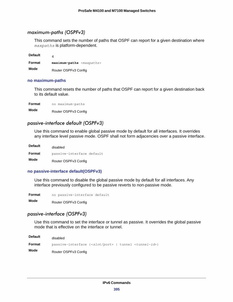
ProSafe M4100 and M7100 Managed Switches
maximum-paths (OSPFv3)
This command sets the number of paths that OSPF can report for a given destination where maxpaths is platform-dependent.
Default
Format maximum-paths <maxpaths>
Mode
no maximum-paths
This command resets the number of paths that OSPF can report for a given destination back to its default value.
Format no maximum-paths
Mode
passive-interface default (OSPFv3)
Use this command to enable global passive mode by default for all interfaces. It overrides any interface level passive mode. OSPF shall not form adjacencies over a passive interface.
Default
Format passive-interface default
Mode
no passive-interface default(OSPFv3)
Use this command to disable the global passive mode by default for all interfaces. Any interface previously configured to be passive reverts to non-passive mode.
Format no passive-interface default
Mode
passive-interface (OSPFv3)
Use this command to set the interface or tunnel as passive. It overrides the global passive mode that is effective on the interface or tunnel.
Default
Format passive-interface {<slot/port> | tunnel <tunnel-id>}
Mode
4
Router OSPFv3 Config
Router OSPFv3 Config
disabled
Router OSPFv3 Config
Router OSPFv3 Config
disabled
Router OSPFv3 Config
IPv6 Commands
395
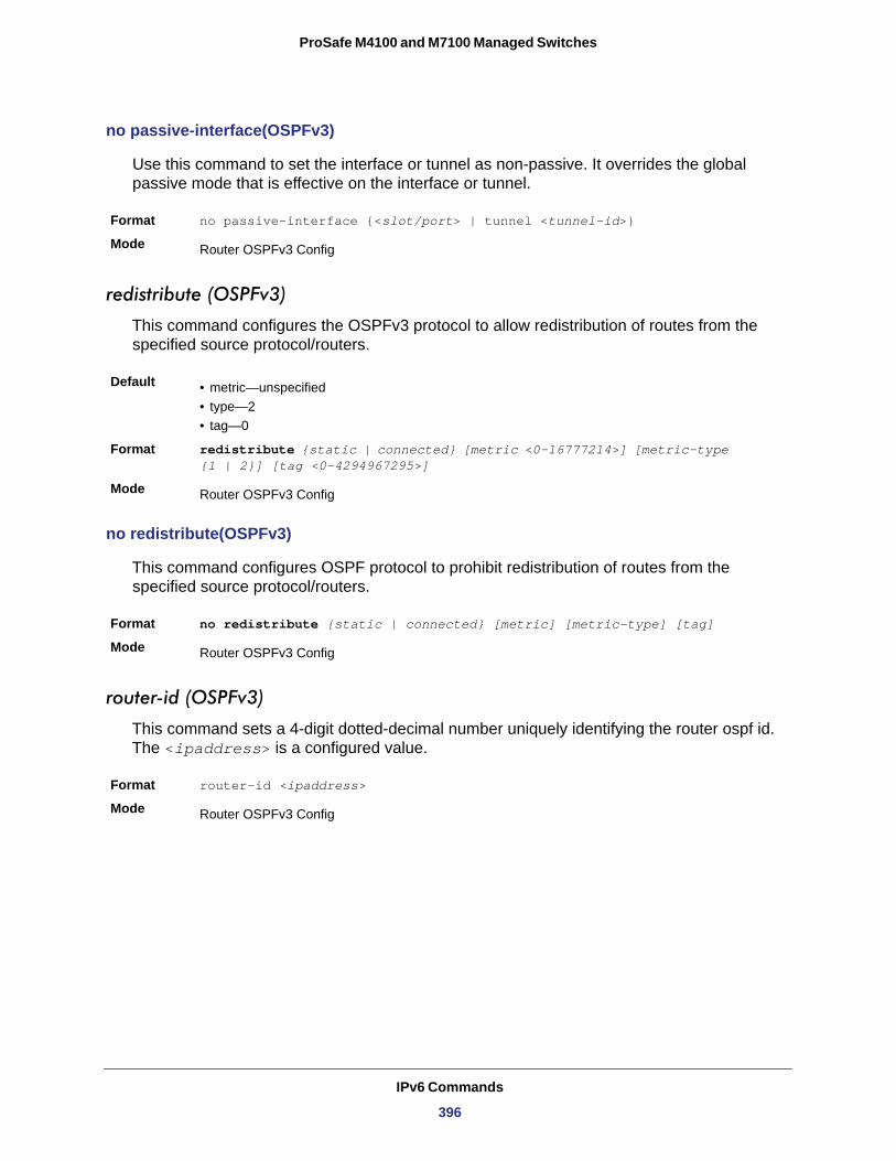
ProSafe M4100 and M7100 Managed Switches
no passive-interface(OSPFv3)
Use this command to set the interface or tunnel as non-passive. It overrides the global passive mode that is effective on the interface or tunnel.
Format no passive-interface {<slot/port> | tunnel <tunnel-id>}
Mode
redistribute (OSPFv3)
This command configures the OSPFv3 protocol to allow redistribution of routes from the specified source protocol/routers.
Default • metric—unspecified• type—2• tag—0
Format redistribute {static | connected} [metric <0-16777214>] [metric-type {1 | 2}] [tag <0-4294967295>]
Mode
no redistribute(OSPFv3)
This command configures OSPF protocol to prohibit redistribution of routes from the specified source protocol/routers.
Format no redistribute {static | connected} [metric] [metric-type] [tag]
Mode
router-id (OSPFv3)
This command sets a 4-digit dotted-decimal number uniquely identifying the router ospf id. The <ipaddress> is a configured value.
Format router-id <ipaddress>
Mode
Router OSPFv3 Config
Router OSPFv3 Config
Router OSPFv3 Config
Router OSPFv3 Config
IPv6 Commands
396
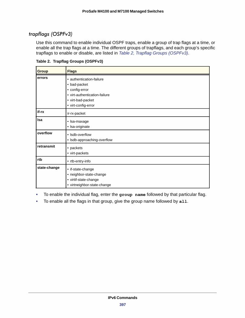
ProSafe M4100 and M7100 Managed Switches
trapflags (OSPFv3)
Use this command to enable individual OSPF traps, enable a group of trap flags at a time, or enable all the trap flags at a time. The different groups of trapflags, and each group’s specific trapflags to enable or disable, are listed in Table 2, Trapflag Groups (OSPFv3).
Table 2. Trapflag Groups (OSPFv3)
errors • authentication-failure• bad-packet• config-error• virt-authentication-failure• virt-bad-packet• virt-config-error
if-rx
lsa • lsa-maxage• lsa-originate
overflow • lsdb-overflow• lsdb-approaching-overflow
retransmit • packets• virt-packets
rtb • rtb-entry-info
state-change • if-state-change• neighbor-state-change• virtif-state-change• virtneighbor-state-change
• To enable the individual flag, enter the group name followed by that particular flag.• To enable all the flags in that group, give the group name followed by all.
Group Flags
ir-rx-packet
IPv6 Commands
397
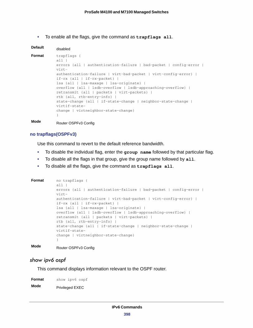
ProSafe M4100 and M7100 Managed Switches
• To enable all the flags, give the command as trapflags all.
Default
Format trapflags { all | errors {all | authentication-failure | bad-packet | config-error | virt- authentication-failure | virt-bad-packet | virt-config-error} | if-rx {all | if-rx-packet} | lsa {all | lsa-maxage | lsa-originate} | overflow {all | lsdb-overflow | lsdb-approaching-overflow} | retransmit {all | packets | virt-packets} |rtb {all, rtb-entry-info} | state-change {all | if-state-change | neighbor-state-change | virtif-state- change | virtneighbor-state-change} }
Mode
no trapflags(OSPFv3)
Use this command to revert to the default reference bandwidth.
• To disable the individual flag, enter the group name followed by that particular flag.• To disable all the flags in that group, give the group name followed by all.• To disable all the flags, give the command as trapflags all.
show ipv6 ospf
This command displays information relevant to the OSPF router.
Format show ipv6 ospf
Mode
disabled
Router OSPFv3 Config
Format no trapflags { all | errors {all | authentication-failure | bad-packet | config-error | virt- authentication-failure | virt-bad-packet | virt-config-error} | if-rx {all | if-rx-packet} | lsa {all | lsa-maxage | lsa-originate} | overflow {all | lsdb-overflow | lsdb-approaching-overflow} | retransmit {all | packets | virt-packets} |rtb {all, rtb-entry-info} | state-change {all | if-state-change | neighbor-state-change | virtif-state- change | virtneighbor-state-change} }
Mode Router OSPFv3 Config
Privileged EXEC
IPv6 Commands
398
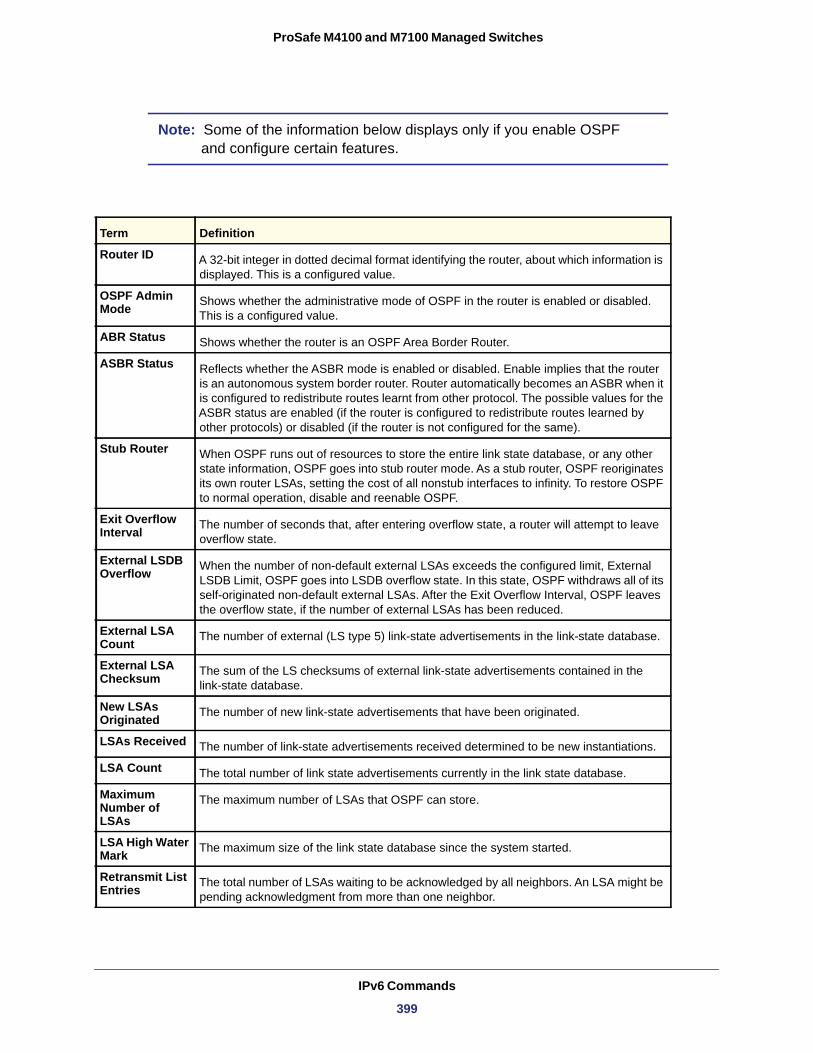
ProSafe M4100 and M7100 Managed Switches
Note: Some of the information below displays only if you enable OSPF and configure certain features.
Term Definition
Router ID A 32-bit integer in dotted decimal format identifying the router, about which information is displayed. This is a configured value.
OSPF Admin Mode Shows whether the administrative mode of OSPF in the router is enabled or disabled.
This is a configured value.
ABR Status Shows whether the router is an OSPF Area Border Router.
ASBR Status Reflects whether the ASBR mode is enabled or disabled. Enable implies that the router is an autonomous system border router. Router automatically becomes an ASBR when it is configured to redistribute routes learnt from other protocol. The possible values for the ASBR status are enabled (if the router is configured to redistribute routes learned by other protocols) or disabled (if the router is not configured for the same).
Stub Router When OSPF runs out of resources to store the entire link state database, or any other state information, OSPF goes into stub router mode. As a stub router, OSPF reoriginates its own router LSAs, setting the cost of all nonstub interfaces to infinity. To restore OSPF to normal operation, disable and reenable OSPF.
Exit Overflow Interval The number of seconds that, after entering overflow state, a router will attempt to leave
overflow state.
External LSDB Overflow When the number of non-default external LSAs exceeds the configured limit, External
LSDB Limit, OSPF goes into LSDB overflow state. In this state, OSPF withdraws all of its self-originated non-default external LSAs. After the Exit Overflow Interval, OSPF leaves the overflow state, if the number of external LSAs has been reduced.
External LSA Count The number of external (LS type 5) link-state advertisements in the link-state database.
External LSA Checksum The sum of the LS checksums of external link-state advertisements contained in the
link-state database.
New LSAs Originated The number of new link-state advertisements that have been originated.
LSAs Received The number of link-state advertisements received determined to be new instantiations.
LSA Count The total number of link state advertisements currently in the link state database.
Maximum Number of LSAs
The maximum number of LSAs that OSPF can store.
LSA High Water Mark The maximum size of the link state database since the system started.
Retransmit List Entries The total number of LSAs waiting to be acknowledged by all neighbors. An LSA might be
pending acknowledgment from more than one neighbor.
IPv6 Commands
399
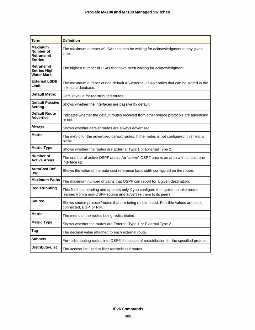
ProSafe M4100 and M7100 Managed Switches
Maximum Number of Retransmit Entries
The maximum number of LSAs that can be waiting for acknowledgment at any given time.
Retransmit Entries High Water Mark
The highest number of LSAs that have been waiting for acknowledgment.
External LSDB Limit The maximum number of non-default AS-external-LSAs entries that can be stored in the
link-state database.
Default Metric Default value for redistributed routes.
Default Passive Setting Shows whether the interfaces are passive by default.
Default Route Advertise Indicates whether the default routes received from other source protocols are advertised
or not.
Always Shows whether default routes are always advertised.
Metric The metric for the advertised default routes. If the metric is not configured, this field is blank.
Metric Type Shows whether the routes are External Type 1 or External Type 2.
Number of Active Areas The number of active OSPF areas. An “active” OSPF area is an area with at least one
interface up.
AutoCost Ref BW Shows the value of the auto-cost reference bandwidth configured on the router.
Maximum Paths The maximum number of paths that OSPF can report for a given destination.
Redistributing This field is a heading and appears only if you configure the system to take routes learned from a non-OSPF source and advertise them to its peers.
Source Shows source protocol/routes that are being redistributed. Possible values are static, connected, BGP, or RIP.
Metric The metric of the routes being redistributed.
Metric Type Shows whether the routes are External Type 1 or External Type 2.
Tag The decimal value attached to each external route.
Subnets For redistributing routes into OSPF, the scope of redistribution for the specified protocol.
Distribute-List The access list used to filter redistributed routes.
Term Definition
IPv6 Commands
400
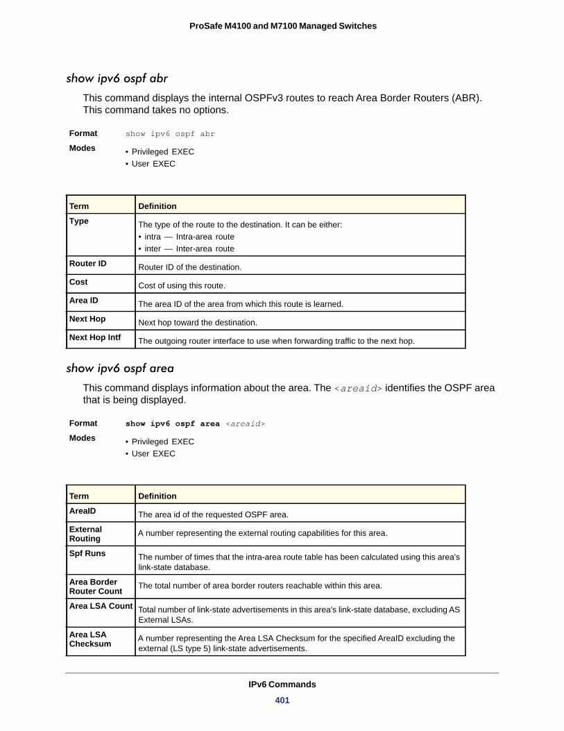
ProSafe M4100 and M7100 Managed Switches
show ipv6 ospf abr
This command displays the internal OSPFv3 routes to reach Area Border Routers (ABR). This command takes no options.
Format show ipv6 ospf abr
Modes • Privileged EXEC• User EXEC
show ipv6 ospf area
This command displays information about the area. The <areaid> identifies the OSPF area that is being displayed.
Format show ipv6 ospf area <areaid>
Modes • Privileged EXEC• User EXEC
Term Definition
Type The type of the route to the destination. It can be either:• intra — Intra-area route• inter — Inter-area route
Router ID Router ID of the destination.
Cost Cost of using this route.
Area ID The area ID of the area from which this route is learned.
Next Hop Next hop toward the destination.
Next Hop Intf The outgoing router interface to use when forwarding traffic to the next hop.
Term Definition
AreaID The area id of the requested OSPF area.
External Routing A number representing the external routing capabilities for this area.
Spf Runs The number of times that the intra-area route table has been calculated using this area's link-state database.
Area Border Router Count The total number of area border routers reachable within this area.
Area LSA Count Total number of link-state advertisements in this area's link-state database, excluding AS External LSAs.
Area LSA Checksum A number representing the Area LSA Checksum for the specified AreaID excluding the
external (LS type 5) link-state advertisements.
IPv6 Commands
401
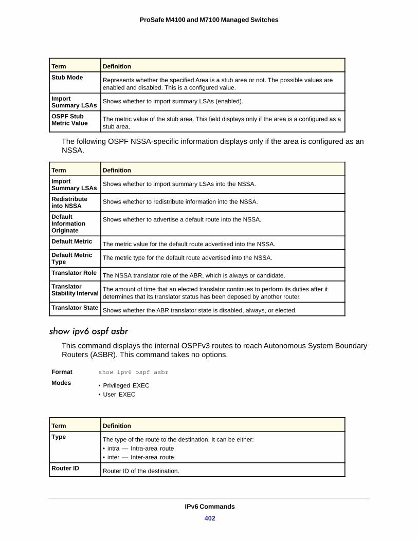
ProSafe M4100 and M7100 Managed Switches
The following OSPF NSSA-specific information displays only if the area is configured as an NSSA.
Import Summary LSAs
Redistribute into NSSA
Default Information Originate
Default Metric
Default Metric Type
Translator Role
Translator Stability Interval
Translator State
show ipv6 ospf asbr
This command displays the internal OSPFv3 routes to reach Autonomous System Boundary Routers (ASBR). This command takes no options.
Format show ipv6 ospf asbr
Modes • Privileged EXEC• User EXEC
Stub Mode Represents whether the specified Area is a stub area or not. The possible values are enabled and disabled. This is a configured value.
Import Summary LSAs Shows whether to import summary LSAs (enabled).
OSPF Stub Metric Value The metric value of the stub area. This field displays only if the area is a configured as a
stub area.
Term Definition
Shows whether to import summary LSAs into the NSSA.
Shows whether to redistribute information into the NSSA.
Shows whether to advertise a default route into the NSSA.
The metric value for the default route advertised into the NSSA.
The metric type for the default route advertised into the NSSA.
The NSSA translator role of the ABR, which is always or candidate.
The amount of time that an elected translator continues to perform its duties after it determines that its translator status has been deposed by another router.
Shows whether the ABR translator state is disabled, always, or elected.
Term Definition
Type The type of the route to the destination. It can be either:• intra — Intra-area route• inter — Inter-area route
Router ID Router ID of the destination.
Term Definition
IPv6 Commands
402
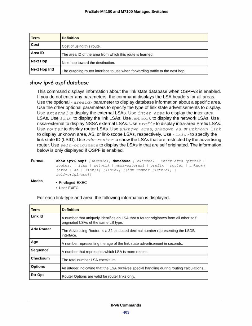
ProSafe M4100 and M7100 Managed Switches
show ipv6 ospf database
This command displays information about the link state database when OSPFv3 is enabled. If you do not enter any parameters, the command displays the LSA headers for all areas. Use the optional <areaid> parameter to display database information about a specific area. Use the other optional parameters to specify the type of link state advertisements to display. Use external to display the external LSAs. Use inter-area to display the inter-area LSAs. Use link to display the link LSAs. Use network to display the network LSAs. Use nssa-external to display NSSA external LSAs. Use prefix to display intra-area Prefix LSAs. Use router to display router LSAs. Use unknown area, unknown as, or unknown link to display unknown area, AS, or link-scope LSAs, respectively. Use <lsid> to specify the link state ID (LSID). Use adv-router to show the LSAs that are restricted by the advertising router. Use self-originate to display the LSAs in that are self originated. The information below is only displayed if OSPF is enabled.
Format show ipv6 ospf [<areaid>] database [{external | inter-area {prefix | router} | link | network | nssa-external | prefix | router | unknown {area | as | link}}] [<lsid>] [{adv-router [<rtrid>] | self-originate}]
Modes • Privileged EXEC• User EXEC
For each link-type and area, the following information is displayed.
Link Id
Adv Router
Age
Sequence
Checksum
Options
Rtr Opt
Cost Cost of using this route.
Area ID The area ID of the area from which this route is learned.
Next Hop Next hop toward the destination.
Next Hop Intf The outgoing router interface to use when forwarding traffic to the next hop.
Term Definition
A number that uniquely identifies an LSA that a router originates from all other self originated LSAs of the same LS type.
The Advertising Router. Is a 32 bit dotted decimal number representing the LSDB interface.
A number representing the age of the link state advertisement in seconds.
A number that represents which LSA is more recent.
The total number LSA checksum.
An integer indicating that the LSA receives special handling during routing calculations.
Router Options are valid for router links only.
Term Definition
IPv6 Commands
403
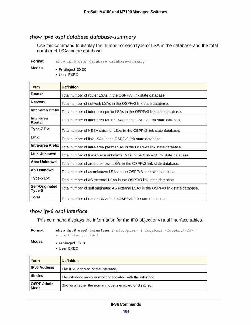
ProSafe M4100 and M7100 Managed Switches
show ipv6 ospf database database-summary
Use this command to display the number of each type of LSA in the database and the total number of LSAs in the database.
Format show ipv6 ospf database database-summary
Modes • Privileged EXEC• User EXEC
Router
Network
Inter-area Prefix
Inter-area Router
Type-7 Ext
Link
Intra-area Prefix
Link Unknown
Area Unknown
AS Unknown
Type-5 Ext
Self-Originated Type-5
Total
show ipv6 ospf interface
This command displays the information for the IFO object or virtual interface tables.
Format show ipv6 ospf interface {<slot/port> | loopback <loopback-id> | tunnel <tunnel-id>}
Modes • Privileged EXEC• User EXEC
Term Definition
Total number of router LSAs in the OSPFv3 link state database.
Total number of network LSAs in the OSPFv3 link state database.
Total number of inter-area prefix LSAs in the OSPFv3 link state database.
Total number of inter-area router LSAs in the OSPFv3 link state database.
Total number of NSSA external LSAs in the OSPFv3 link state database.
Total number of link LSAs in the OSPFv3 link state database.
Total number of intra-area prefix LSAs in the OSPFv3 link state database.
Total number of link-source unknown LSAs in the OSPFv3 link state database.
Total number of area unknown LSAs in the OSPFv3 link state database.
Total number of as unknown LSAs in the OSPFv3 link state database.
Total number of AS external LSAs in the OSPFv3 link state database.
Total number of self originated AS external LSAs in the OSPFv3 link state database.
Total number of router LSAs in the OSPFv3 link state database.
Term Definition
IPv6 Address The IPv6 address of the interface.
ifIndex The interface index number associated with the interface.
OSPF Admin Mode Shows whether the admin mode is enabled or disabled.
IPv6 Commands
404
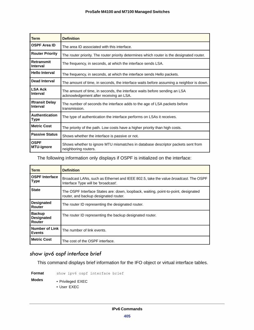
ProSafe M4100 and M7100 Managed Switches
The following information only displays if OSPF is initialized on the interface:
OSPF Interface Type
State
Designated Router
Backup Designated Router
Number of Link Events
Metric Cost
show ipv6 ospf interface brief
This command displays brief information for the IFO object or virtual interface tables.
Format show ipv6 ospf interface brief
Modes • Privileged EXEC• User EXEC
OSPF Area ID The area ID associated with this interface.
Router Priority The router priority. The router priority determines which router is the designated router.
Retransmit Interval The frequency, in seconds, at which the interface sends LSA.
Hello Interval The frequency, in seconds, at which the interface sends Hello packets.
Dead Interval The amount of time, in seconds, the interface waits before assuming a neighbor is down.
LSA Ack Interval The amount of time, in seconds, the interface waits before sending an LSA
acknowledgement after receiving an LSA.
Iftransit Delay Interval The number of seconds the interface adds to the age of LSA packets before
transmission.
Authentication Type The type of authentication the interface performs on LSAs it receives.
Metric Cost The priority of the path. Low costs have a higher priority than high costs.
Passive Status Shows whether the interface is passive or not.
OSPF MTU-ignore Shows whether to ignore MTU mismatches in database descriptor packets sent from
neighboring routers.
Term Definition
Broadcast LANs, such as Ethernet and IEEE 802.5, take the value broadcast. The OSPF Interface Type will be 'broadcast'.
The OSPF Interface States are: down, loopback, waiting, point-to-point, designated router, and backup designated router.
The router ID representing the designated router.
The router ID representing the backup designated router.
The number of link events.
The cost of the OSPF interface.
Term Definition
IPv6 Commands
405
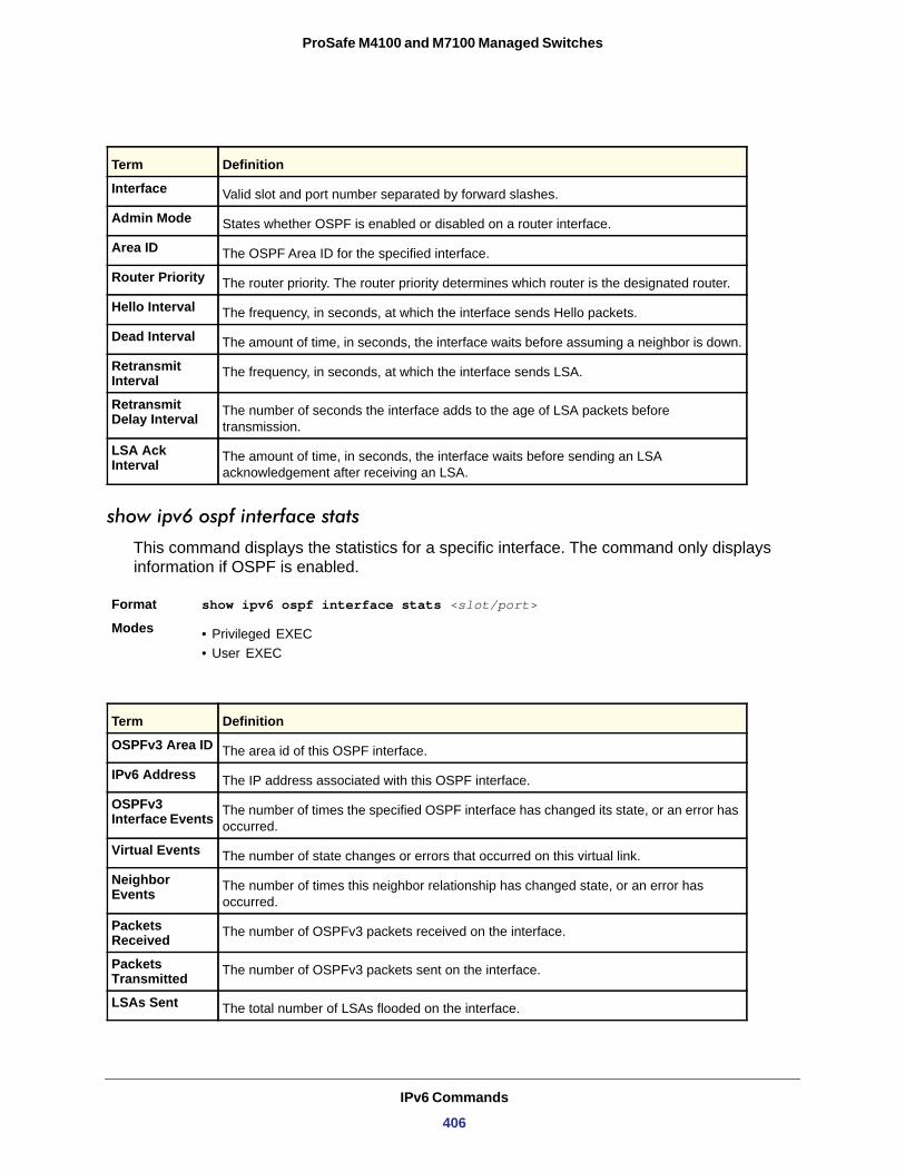
ProSafe M4100 and M7100 Managed Switches
show ipv6 ospf interface stats
This command displays the statistics for a specific interface. The command only displays information if OSPF is enabled.
Format show ipv6 ospf interface stats <slot/port>
Modes • Privileged EXEC• User EXEC
Term Definition
Interface Valid slot and port number separated by forward slashes.
Admin Mode States whether OSPF is enabled or disabled on a router interface.
Area ID The OSPF Area ID for the specified interface.
Router Priority The router priority. The router priority determines which router is the designated router.
Hello Interval The frequency, in seconds, at which the interface sends Hello packets.
Dead Interval The amount of time, in seconds, the interface waits before assuming a neighbor is down.
Retransmit Interval The frequency, in seconds, at which the interface sends LSA.
Retransmit Delay Interval The number of seconds the interface adds to the age of LSA packets before
transmission.
LSA Ack Interval The amount of time, in seconds, the interface waits before sending an LSA
acknowledgement after receiving an LSA.
Term Definition
OSPFv3 Area ID The area id of this OSPF interface.
IPv6 Address The IP address associated with this OSPF interface.
OSPFv3 Interface Events The number of times the specified OSPF interface has changed its state, or an error has
occurred.
Virtual Events The number of state changes or errors that occurred on this virtual link.
Neighbor Events The number of times this neighbor relationship has changed state, or an error has
occurred.
Packets Received The number of OSPFv3 packets received on the interface.
Packets Transmitted The number of OSPFv3 packets sent on the interface.
LSAs Sent The total number of LSAs flooded on the interface.
IPv6 Commands
406
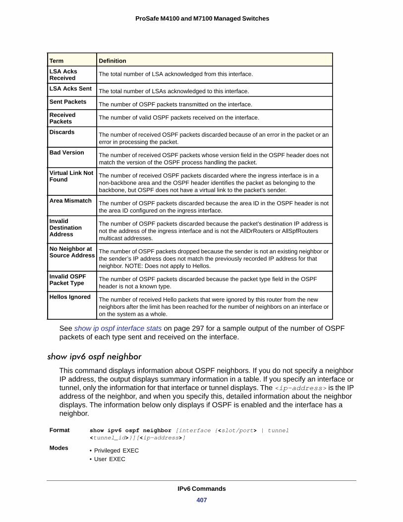
ProSafe M4100 and M7100 Managed Switches
See show ip ospf interface stats on page 297 for a sample output of the number of OSPF packets of each type sent and received on the interface.
show ipv6 ospf neighbor
This command displays information about OSPF neighbors. If you do not specify a neighbor IP address, the output displays summary information in a table. If you specify an interface or tunnel, only the information for that interface or tunnel displays. The <ip-address> is the IP address of the neighbor, and when you specify this, detailed information about the neighbor displays. The information below only displays if OSPF is enabled and the interface has a neighbor.
Format show ipv6 ospf neighbor [interface {<slot/port> | tunnel <tunnel_id>}][<ip-address>]
Modes • Privileged EXEC• User EXEC
LSA Acks Received The total number of LSA acknowledged from this interface.
LSA Acks Sent The total number of LSAs acknowledged to this interface.
Sent Packets The number of OSPF packets transmitted on the interface.
Received Packets The number of valid OSPF packets received on the interface.
Discards The number of received OSPF packets discarded because of an error in the packet or an error in processing the packet.
Bad Version The number of received OSPF packets whose version field in the OSPF header does not match the version of the OSPF process handling the packet.
Virtual Link Not Found The number of received OSPF packets discarded where the ingress interface is in a
non-backbone area and the OSPF header identifies the packet as belonging to the backbone, but OSPF does not have a virtual link to the packet’s sender.
Area Mismatch The number of OSPF packets discarded because the area ID in the OSPF header is not the area ID configured on the ingress interface.
Invalid Destination Address
The number of OSPF packets discarded because the packet’s destination IP address is not the address of the ingress interface and is not the AllDrRouters or AllSpfRouters multicast addresses.
No Neighbor at Source Address The number of OSPF packets dropped because the sender is not an existing neighbor or
the sender’s IP address does not match the previously recorded IP address for that neighbor. NOTE: Does not apply to Hellos.
Invalid OSPF Packet Type The number of OSPF packets discarded because the packet type field in the OSPF
header is not a known type.
Hellos Ignored The number of received Hello packets that were ignored by this router from the new neighbors after the limit has been reached for the number of neighbors on an interface or on the system as a whole.
Term Definition
IPv6 Commands
407
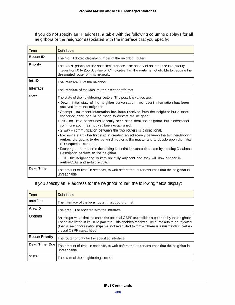
ProSafe M4100 and M7100 Managed Switches
If you do not specify an IP address, a table with the following columns displays for all neighbors or the neighbor associated with the interface that you specify:
Router ID
Priority
Intf ID
Interface
State
• Down- initial state of the neighbor conversation - no recent information has been received from the neighbor.
• Attempt - no recent information has been received from the neighbor but a more concerted effort should be made to contact the neighbor.
• Init - an Hello packet has recently been seen from the neighbor, but bidirectional communication has not yet been established.
• 2 way - communication between the two routers is bidirectional. • Exchange start - the first step in creating an adjacency between the two neighboring
routers, the goal is to decide which router is the master and to decide upon the initial DD sequence number.
• Exchange - the router is describing its entire link state database by sending Database Description packets to the neighbor.
• Full - the neighboring routers are fully adjacent and they will now appear in router-LSAs and network-LSAs.
Dead Time
If you specify an IP address for the neighbor router, the following fields display:
Term Definition
The 4-digit dotted-decimal number of the neighbor router.
The OSPF priority for the specified interface. The priority of an interface is a priority integer from 0 to 255. A value of '0' indicates that the router is not eligible to become the designated router on this network.
The interface ID of the neighbor.
The interface of the local router in slot/port format.
The state of the neighboring routers. The possible values are:
The amount of time, in seconds, to wait before the router assumes that the neighbor is unreachable.
Term Definition
Interface The interface of the local router in slot/port format.
Area ID The area ID associated with the interface.
Options An integer value that indicates the optional OSPF capabilities supported by the neighbor. These are listed in its Hello packets. This enables received Hello Packets to be rejected (that is, neighbor relationships will not even start to form) if there is a mismatch in certain crucial OSPF capabilities.
Router Priority The router priority for the specified interface.
Dead Timer Due The amount of time, in seconds, to wait before the router assumes that the neighbor is unreachable.
State The state of the neighboring routers.
IPv6 Commands
408
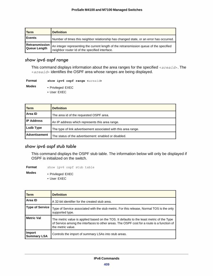
ProSafe M4100 and M7100 Managed Switches
show ipv6 ospf range
This command displays information about the area ranges for the specified <areaid>. The <areaid> identifies the OSPF area whose ranges are being displayed.
Format show ipv6 ospf range <areaid>
Modes • Privileged EXEC• User EXEC
show ipv6 ospf stub table
This command displays the OSPF stub table. The information below will only be displayed if OSPF is initialized on the switch.
Format show ipv6 ospf stub table
Modes • Privileged EXEC• User EXEC
Events Number of times this neighbor relationship has changed state, or an error has occurred.
Retransmission Queue Length An integer representing the current length of the retransmission queue of the specified
neighbor router Id of the specified interface.
Term Definition
Area ID The area id of the requested OSPF area.
IP Address An IP address which represents this area range.
Lsdb Type The type of link advertisement associated with this area range.
Advertisement The status of the advertisement: enabled or disabled.
Term Definition
Area ID A 32-bit identifier for the created stub area.
Type of Service Type of Service associated with the stub metric. For this release, Normal TOS is the only supported type.
Metric Val The metric value is applied based on the TOS. It defaults to the least metric of the Type of Service among the interfaces to other areas. The OSPF cost for a route is a function of the metric value.
Import Summary LSA Controls the import of summary LSAs into stub areas.
Term Definition
IPv6 Commands
409
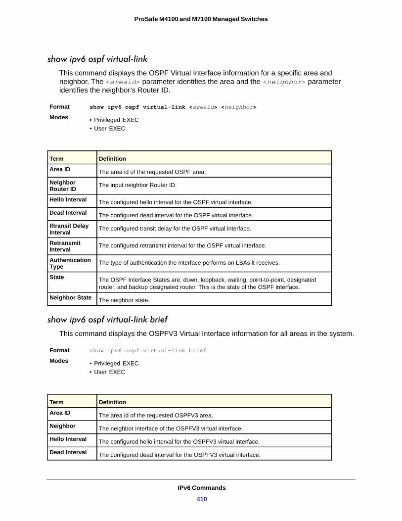
ProSafe M4100 and M7100 Managed Switches
show ipv6 ospf virtual-link
This command displays the OSPF Virtual Interface information for a specific area and neighbor. The <areaid> parameter identifies the area and the <neighbor> parameter identifies the neighbor’s Router ID.
Format show ipv6 ospf virtual-link <areaid> <neighbor>
Modes • Privileged EXEC• User EXEC
show ipv6 ospf virtual-link brief
This command displays the OSPFV3 Virtual Interface information for all areas in the system.
Format show ipv6 ospf virtual-link brief
Modes • Privileged EXEC• User EXEC
Term Definition
Area ID The area id of the requested OSPF area.
Neighbor Router ID The input neighbor Router ID.
Hello Interval The configured hello interval for the OSPF virtual interface.
Dead Interval The configured dead interval for the OSPF virtual interface.
Iftransit Delay Interval The configured transit delay for the OSPF virtual interface.
Retransmit Interval The configured retransmit interval for the OSPF virtual interface.
Authentication Type The type of authentication the interface performs on LSAs it receives.
State The OSPF Interface States are: down, loopback, waiting, point-to-point, designated router, and backup designated router. This is the state of the OSPF interface.
Neighbor State The neighbor state.
Term Definition
Area ID The area id of the requested OSPFV3 area.
Neighbor The neighbor interface of the OSPFV3 virtual interface.
Hello Interval The configured hello interval for the OSPFV3 virtual interface.
Dead Interval The configured dead interval for the OSPFV3 virtual interface.
IPv6 Commands
410
ProSafe M4100 and M7100 Managed Switches
OSPFv3 Graceful Restart Commands
The managed switch implementation of OSPFv3 supports graceful restart as specified in RFC 5187 and RFC 3623. Graceful restart works together with managed switch non-stop forwarding (nsf) to enable the hardware to continue forwarding IPv6 packets using OSPFv3 routes while a backup unit takes over management unit responsibility. When OSPF executes a graceful restart, it informs its neighbors that the OSPF control plane is restarting but will be back shortly. Helpful neighbors continue to advertise to the network that they have full adjacencies with the restarting router, avoiding announcement of a topology change, and related events (for example, flooding of LSAs and SPF runs). Helpful neighbors continue to forward packets through the restarting router. The restarting router relearns the network topology from its helpful neighbors.
Graceful restart implements both the restarting router and helpful neighbor features described in RFC 3623.
nsf (OSPFv3)
This command enables OSPF graceful restart. The ietf parameter is used to distinguish the IETF standard implementation of graceful restart from other implementations. Since the IETF implementation is not the only one supported, this parameter is optional. The planned-only parameter indicates that OSPF performs a graceful restart only when the restart is planned (that is, when the restart results from the initiate failover command).
Default
Format nsf [ ietf ] [ planned-only ]
Mode
no nsf [ietf] (OSPFv3)
This command disables OSPF graceful restart.
Format no nsf [ ietf ]
Mode
nsf helper (OSPFv3)
This command allows OSPF to act as a helpful neighbor for a restarting router. The planned-only parameter indicates that OSPF should only help a restarting router performing a planned restart.
Retransmit Interval The configured retransmit interval for the OSPFV3 virtual interface.
Transit Delay The configured transit delay for the OSPFV3 virtual interface.
disabled
OSPFv3 Router Configuration mode
OSPFv3 Router Configuration mode
Term Definition
IPv6 Commands
411
ProSafe M4100 and M7100 Managed Switches
The grace LSA announcing the graceful restart includes the reason for the restart. Reasons 1 (software restart) and 2 (software reload/upgrade) are considered planned restarts. Reasons 0 (unknown) and 3 (switch to redundant control processor) are considered unplanned restarts.
Default
Format nsf helper [ planned-only ]
Mode
nsf ietf helper disable (OSPFv3)
This command is functionally equivalent to no nsf helper and is supported solely for IS-CLI compatibility.
Format nsf ietf helper disable
Mode
no nsf helper (OSPFv3)
This command prevents OSPF from acting as a helpful neighbor.
Format no nsf helper
Mode
nsf helper strict-lsa-checking (OSPFv3)
This command requires that an OSPF helpful neighbor exit helper mode when a topology change occurs. The restarting router is unable to react to topology changes. In particular, the restarting router will not immediately update its forwarding table. Therefore, a topology change might introduce forwarding loops or black holes that persist until the graceful restart is completed. By exiting graceful restart when a topology change occurs, a router tries to eliminate the loops or black holes as quickly as possible by routing around the restarting router.
The ietf parameter is used to distinguish the IETF standard implementation of graceful restart from other implementations. Since the IETF implementation is not the only one supported, this parameter is optional.
A helpful neighbor considers a link down with the restarting router to be a topology change, regardless of the strict LSA checking configuration.
Default
Format nsf [ietf] helper strict-lsa-checking
Mode
OSPF acts as a helpful neighbor for both planned and unplanned restarts
OSPFv3 Router Configuration mode
OSPFv3 Router Configuration mode
OSPFv3 Router Configuration mode
A helpful neighbor exits helper mode when a topology change occurs.
OSPFv3 Router Configuration mode
IPv6 Commands
412
ProSafe M4100 and M7100 Managed Switches
no nsf [ietf] helper strict-lsa-checking (OSPFv3)
This command allows OSPF to continue as a helpful neighbor in spite of topology changes.
nsf restart-interval (OSPFv3)
This command configures the length of the grace period on the restarting router. The grace period must be set long enough to allow the restarting router to reestablish all of its adjacencies and complete a full database exchange with each of its neighbors.
The ietf parameter is used to distinguish the IETF standard implementation of graceful restart from other implementations. Since the IETF implementation is not the only one supported, this parameter is optional. The seconds parameter represents the number of seconds that the restarting router asks its neighbors to wait before exiting helper mode. The restarting router includes the restart interval in its grace LSAs (range 1–1800 seconds).
Default
Format nsf [ietf] restart-interval seconds
Mode
no [ietf] nsf restart-interval (OSPFv3)
This command reverts the grace period to its default.
DHCPv6 Commands
This section describes the command you use to configure the DHCPv6 server on the system and to view DHCPv6 information.
service dhcpv6
This command enables DHCPv6 configuration on the router.
Default
Format service dhcpv6
Mode
no service dhcpv6
This command disables DHCPv6 configuration on router.
Format no service dhcpv6
Mode
120s
OSPFv3 Router Configuration mode
disabled
Global Config
Global Config
IPv6 Commands
413
ProSafe M4100 and M7100 Managed Switches
ipv6 dhcp server
Use this command to configure DHCPv6 server functionality on an interface. The <pool-name> is the DHCPv6 pool containing stateless and/or prefix delegation parameters, rapid-commit is an option that allows for an abbreviated exchange between the client and server, and <pref-value> is a value used by clients to determine preference between multiple DHCPv6 servers. For a particular interface DHCPv6 server and DHCPv6 relay functions are mutually exclusive.
Format ipv6 dhcp server <pool-name> [rapid-commit] [preference <pref-value>]
Mode
ipv6 dhcp relay destination
Use this command to configure an interface for DHCPv6 relay functionality. Use the destination keyword to set the relay server IPv6 address. The <relay-address> parameter is an IPv6 address of a DHCPv6 relay server. Use the interface keyword to set the relay server interface. The <relay-interface> parameter is an interface (slot/port) to reach a relay server. The optional remote-id is the Relay Agent Information Option “remote ID” sub-option to be added to relayed messages. This can either be the special keyword duid-ifid, which causes the “remote ID” to be derived from the DHCPv6 server DUID and the relay interface number, or it can be specified as a user-defined string.
Note: If <relay-address> is an IPv6 global address, <relay-interface> is not required. If <relay-address> is a link-local or multicast address, <relay-interface> is required. Finally, if you do not specify a value for <relay-address>, you must specify a value for <relay-interface> and the DHCPV6-ALL-AGENTS multicast address (that is, FF02::1:2) is used to relay DHCPv6 messages to the relay server.
ipv6 dhcp pool
Use this command from Global Config mode to enter IPv6 DHCP Pool Config mode. Use the exit command to return to Global Config mode. To return to the User EXEC mode, enter CTRL+Z. The <pool-name> should be less than 31 alpha-numeric characters. DHCPv6 pools are used to specify information for DHCPv6 server to distribute to DHCPv6 clients.
Interface Config
Format ipv6 dhcp relay {destination [<relay-address>] interface [<relay-interface>]| interface [<relay-interface>]} [remote-id (duid-ifid | <user-defined-string>)]
Mode Interface Config
IPv6 Commands
414
ProSafe M4100 and M7100 Managed Switches
These pools are shared between multiple interfaces over which DHCPv6 server capabilities are configured.
Format ipv6 dhcp pool <pool-name>
Mode
no ipv6 dhcp pool
This command removes the specified DHCPv6 pool.
Format no ipv6 dhcp pool <pool-name>
Mode
domain-name (IPv6)
This command sets the DNS domain name provided to the DHCPv6 client by the DHCPv6 server. The DNS domain name is configured for stateless server support and consists of no more than 31 alpha-numeric characters. The DHCPv6 pool can have up to eight domain names.
Format domain-name <dns-domain-name>
Mode
no domain-name
This command removes the DHCPv6 domain name from the DHCPv6 pool.
Format no domain-name <dns-domain-name>
Mode
dns-server (IPv6)
This command sets the ipv6 DNS server address, which is provided to dhcpv6 client by dhcpv6 server. DNS server address is configured for stateless server support. DHCPv6 pool can have multiple number of domain names with maximum of 8.
Format dns-server <dns-server-address>
Mode
no dns-server
This command will remove DHCPv6 server address from DHCPv6 server.
Format no dns-server <dns-server-address>
Mode
Global Config
Global Config
IPv6 DHCP Pool Config
IPv6 DHCP Pool Config
IPv6 DHCP Pool Config
IPv6 DHCP Pool Config
IPv6 Commands
415
ProSafe M4100 and M7100 Managed Switches
prefix-delegation (IPv6)
Multiple IPv6 prefixes can be defined within a pool for distributing to specific DHCPv6 Prefix delegation clients. Prefix is the delegated IPv6 prefix. DUID is the client’s unique DUID value (Example: 00:01:00:09:f8:79:4e:00:04:76:73:43:76'). Name is 31 characters textual client’s name, which is useful for logging or tracing only. Valid lifetime is the valid lifetime for the delegated prefix in seconds and preferred lifetime is the preferred lifetime for the delegated prefix in seconds.
Default • valid-lifetime—2592000• preferred-lifetime—604800
Format prefix-delegation <prefix/prefixlength> <DUID> [name <hostname>] [valid-lifetime <0-4294967295>][preferred-lifetime < 0-4294967295>]
Mode
no prefix-delegation
This command deletes a specific prefix-delegation client.
Format no prefix-delegation <prefix/prefix-delegation> <DUID>Mode
show ipv6 dhcp
This command displays the DHCPv6 server name and status.
Format show ipv6 dhcp
Mode
DHCPv6 is Enabled (Disabled)
Server DUID
show ipv6 dhcp statistics
This command displays the IPv6 DHCP statistics for all interfaces.
Format show ipv6 dhcp statistics
Mode
IPv6 DHCP Pool Config
IPv6 DHCP Pool Config
Privileged EXEC
Term Definition
The status of the DHCPv6 server.
If configured, shows the DHCPv6 unique identifier.
Privileged EXEC
IPv6 Commands
416
ProSafe M4100 and M7100 Managed Switches
Term Definition
DHCPv6 Solicit Packets Received Number of solicit received statistics.
DHCPv6 Request Packets Received Number of request received statistics.
DHCPv6 Confirm Packets Received Number of confirm received statistics.
DHCPv6 Renew Packets Received Number of renew received statistics.
DHCPv6 Rebind Packets Received Number of rebind received statistics.
DHCPv6 Release Packets Received Number of release received statistics.
DHCPv6 Decline Packets Received Number of decline received statistics.
DHCPv6 Inform Packets Received Number of inform received statistics.
DHCPv6 Relay-forward Packets Received Number of relay forward received statistics.
DHCPv6 Relay-reply Packets Received Number of relay-reply received statistics.
DHCPv6 Malformed Packets Received Number of malformed packets statistics.
Received DHCPv6 Packets Discarded Number of DHCP discarded statistics.
Total DHCPv6 Packets Received Total number of DHCPv6 received statistics
DHCPv6 Advertisement Packets Transmitted Number of advertise sent statistics.
DHCPv6 Reply Packets Transmitted Number of reply sent statistics.
DHCPv6 Reconfig Packets Transmitted Number of reconfigure sent statistics.
DHCPv6 Relay-reply Packets Transmitted Number of relay-reply sent statistics.
DHCPv6 Relay-forward Packets Transmitted Number of relay-forward sent statistics.
Total DHCPv6 Packets Transmitted Total number of DHCPv6 sent statistics.
IPv6 Commands
417
ProSafe M4100 and M7100 Managed Switches
show ipv6 dhcp interface
This command displays DHCPv6 information for all relevant interfaces or the specified interface. If you specify an interface, you can use the optional statistics parameter to view statistics for the specified interface.
Format show ipv6 dhcp interface <slot/port> [statistics]
Mode
IPv6 Interface
Mode
If the interface mode is server, the following information displays.
Pool Name
Server Preference
Option Flags
If the interface mode is relay, the following information displays.
Relay Address
Relay Interface Number
Relay Remote ID
Option Flags
If you use the statistics parameter, the command displays the IPv6 DHCP statistics for the specified interface. See show ipv6 dhcp statistics on page 416 for information about the output.
clear ipv6 dhcp
Use this command to clear DHCPv6 statistics for all interfaces or for a specific interface. Use the <slot/port> parameter to specify the interface.
Format clear ipv6 dhcp {statistics | interface <slot/port> statistics}
Mode
Privileged EXEC
Term Definition
The interface name in <slot/port> format.
Shows whether the interface is a IPv6 DHCP relay or server.
Term Definition
The pool name specifying information for DHCPv6 server distribution to DHCPv6 clients.
The preference of the server.
Shows whether rapid commit is enabled.
Term Definition
The IPv6 address of the relay server.
The relay server interface in <slot/port> format.
If configured, shows the name of the relay remote.
Shows whether rapid commit is configured.
Privileged EXEC
IPv6 Commands
418
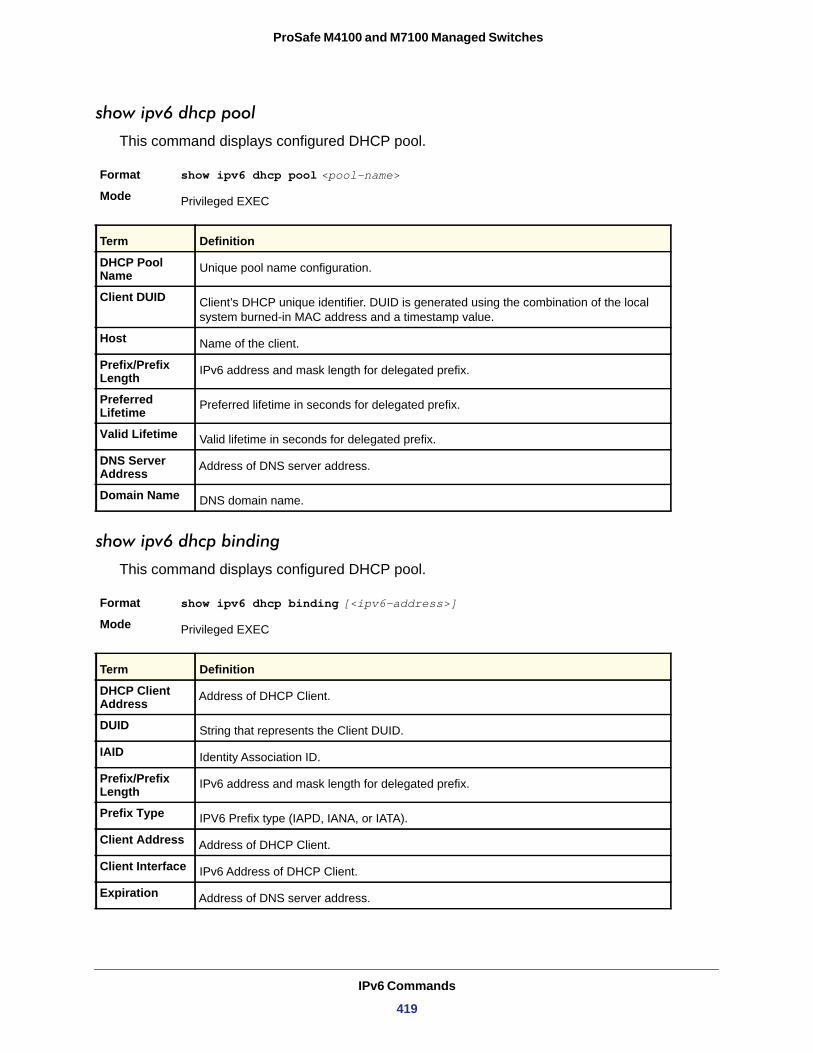
ProSafe M4100 and M7100 Managed Switches
show ipv6 dhcp pool
This command displays configured DHCP pool.
Format show ipv6 dhcp pool <pool-name>Mode
DHCP Pool Name
Client DUID
Host
Prefix/Prefix Length
Preferred Lifetime
Valid Lifetime
DNS Server Address
Domain Name
show ipv6 dhcp binding
This command displays configured DHCP pool.
Format show ipv6 dhcp binding [<ipv6-address>]Mode
Privileged EXEC
Term Definition
Unique pool name configuration.
Client’s DHCP unique identifier. DUID is generated using the combination of the local system burned-in MAC address and a timestamp value.
Name of the client.
IPv6 address and mask length for delegated prefix.
Preferred lifetime in seconds for delegated prefix.
Valid lifetime in seconds for delegated prefix.
Address of DNS server address.
DNS domain name.
Privileged EXEC
Term Definition
DHCP Client Address Address of DHCP Client.
DUID String that represents the Client DUID.
IAID Identity Association ID.
Prefix/Prefix Length IPv6 address and mask length for delegated prefix.
Prefix Type IPV6 Prefix type (IAPD, IANA, or IATA).
Client Address Address of DHCP Client.
Client Interface IPv6 Address of DHCP Client.
Expiration Address of DNS server address.
IPv6 Commands
419
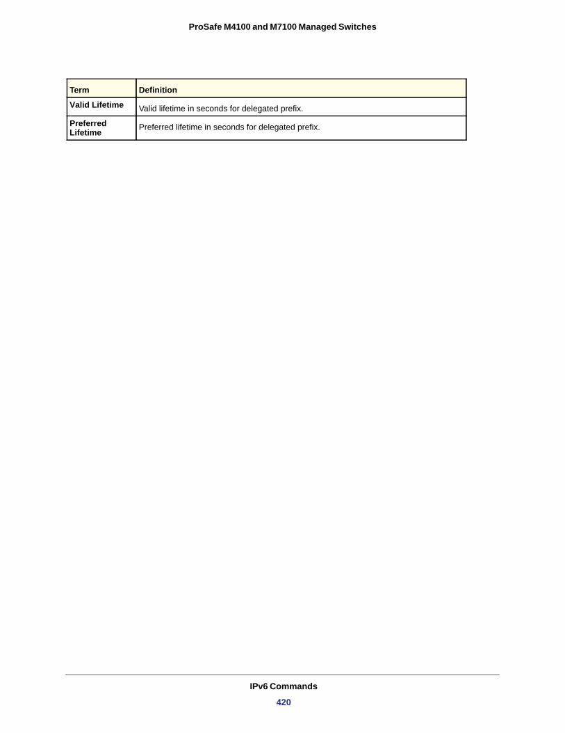
ProSafe M4100 and M7100 Managed Switches
Valid Lifetime Valid lifetime in seconds for delegated prefix.
Preferred Lifetime Preferred lifetime in seconds for delegated prefix.
Term Definition
IPv6 Commands
420
7
7. IPv6 Multicast CommandsThis chapter describes the IPv6 multicast commands available in the managed switch CLI.
Note: Some commands described in this chapter require a license. For more information, see Licensing and Command Support on page 8.
This chapter contains the following sections:
• IPv6 Multicast Forwarder Commands on page 422• IPv6 PIM Commands on page 424• IPv6 MLD Commands on page 431• IPv6 MLD-Proxy Commands on page 437
The commands in this chapter are in three functional groups:
• Show commands display switch settings, statistics, and other information.• Configuration commands configure features and options of the switch. Every switch
command has a show command that displays the configuration setting.• Clear commands clear some or all of the settings to factory defaults.
Note: There is no specific IP multicast enable for IPv6. Enabling of multicast at global config is common for both IPv4 and IPv6.
421
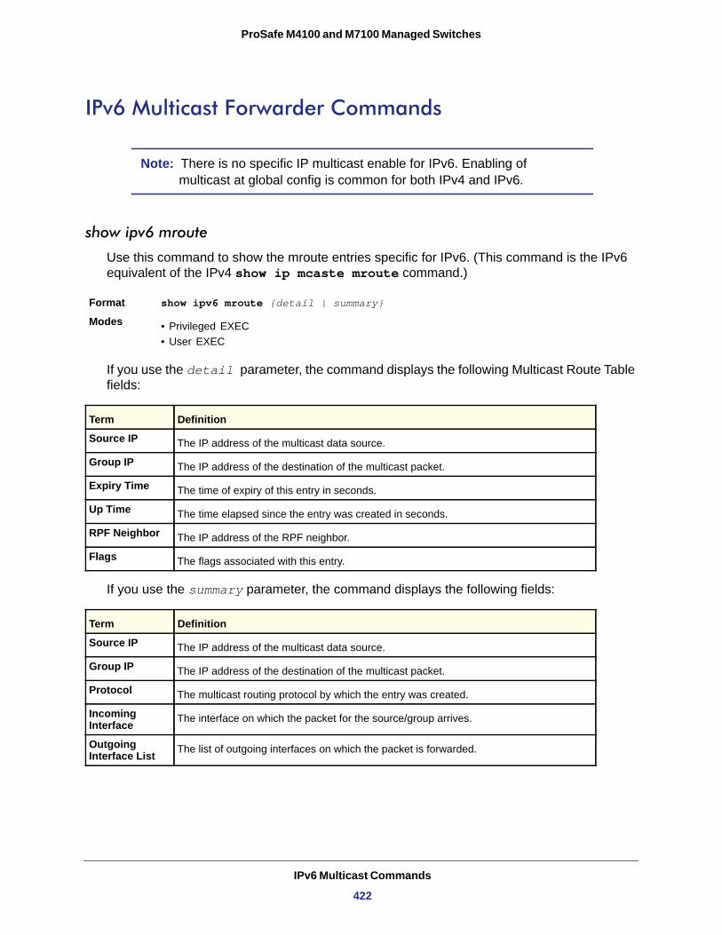
ProSafe M4100 and M7100 Managed Switches
IPv6 Multicast Forwarder Commands
Note: There is no specific IP multicast enable for IPv6. Enabling of multicast at global config is common for both IPv4 and IPv6.
show ipv6 mroute
Use this command to show the mroute entries specific for IPv6. (This command is the IPv6 equivalent of the IPv4 show ip mcaste mroute command.)
Format show ipv6 mroute {detail | summary}
Modes • Privileged EXEC• User EXEC
If you use the detail parameter, the command displays the following Multicast Route Table fields:
Source IP
Group IP
Expiry Time
Up Time
RPF Neighbor
Flags
If you use the summary parameter, the command displays the following fields:
Source IP
Group IP
Protocol
Incoming Interface
Outgoing Interface List
Term Definition
The IP address of the multicast data source.
The IP address of the destination of the multicast packet.
The time of expiry of this entry in seconds.
The time elapsed since the entry was created in seconds.
The IP address of the RPF neighbor.
The flags associated with this entry.
Term Definition
The IP address of the multicast data source.
The IP address of the destination of the multicast packet.
The multicast routing protocol by which the entry was created.
The interface on which the packet for the source/group arrives.
The list of outgoing interfaces on which the packet is forwarded.
IPv6 Multicast Commands
422
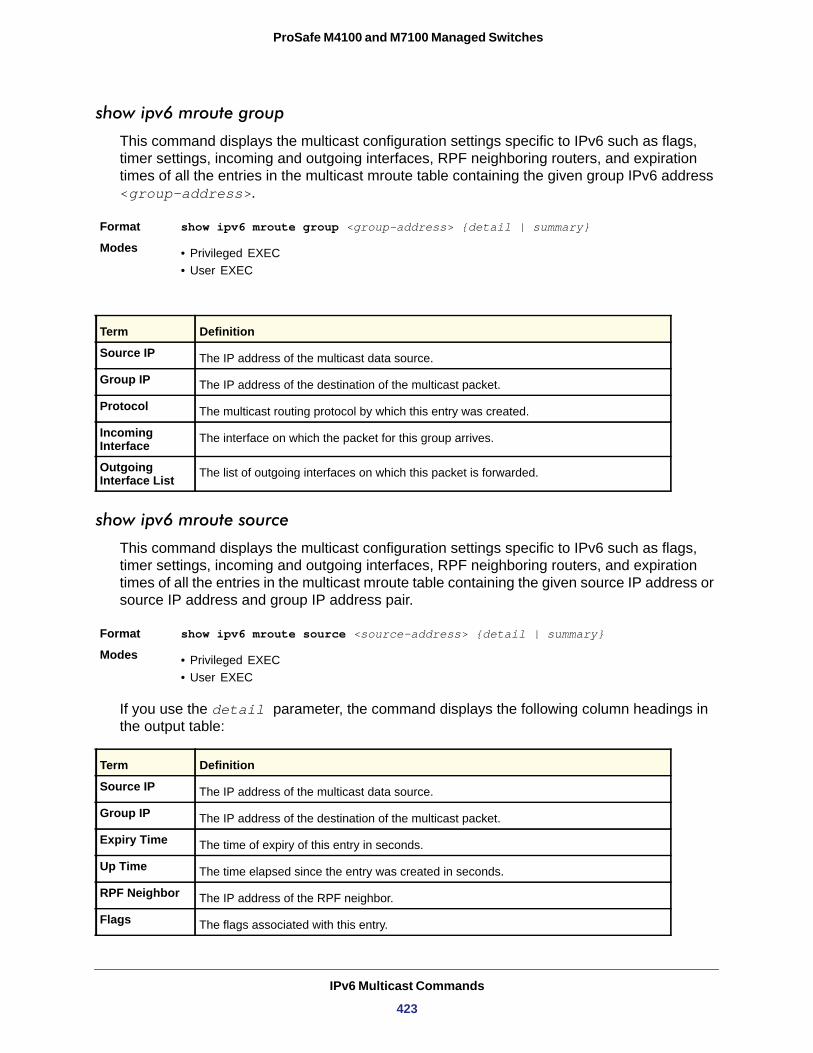
ProSafe M4100 and M7100 Managed Switches
show ipv6 mroute group
This command displays the multicast configuration settings specific to IPv6 such as flags, timer settings, incoming and outgoing interfaces, RPF neighboring routers, and expiration times of all the entries in the multicast mroute table containing the given group IPv6 address <group-address>.
Format show ipv6 mroute group <group-address> {detail | summary}
Modes • Privileged EXEC• User EXEC
show ipv6 mroute source
This command displays the multicast configuration settings specific to IPv6 such as flags, timer settings, incoming and outgoing interfaces, RPF neighboring routers, and expiration times of all the entries in the multicast mroute table containing the given source IP address or source IP address and group IP address pair.
Format show ipv6 mroute source <source-address> {detail | summary}
Modes • Privileged EXEC• User EXEC
If you use the detail parameter, the command displays the following column headings in the output table:
Source IP
Group IP
Expiry Time
Up Time
RPF Neighbor
Flags
Term Definition
Source IP The IP address of the multicast data source.
Group IP The IP address of the destination of the multicast packet.
Protocol The multicast routing protocol by which this entry was created.
Incoming Interface The interface on which the packet for this group arrives.
Outgoing Interface List The list of outgoing interfaces on which this packet is forwarded.
Term Definition
The IP address of the multicast data source.
The IP address of the destination of the multicast packet.
The time of expiry of this entry in seconds.
The time elapsed since the entry was created in seconds.
The IP address of the RPF neighbor.
The flags associated with this entry.
IPv6 Multicast Commands
423
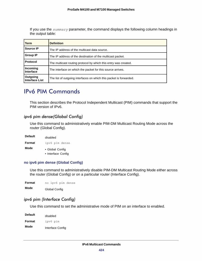
ProSafe M4100 and M7100 Managed Switches
If you use the summary parameter, the command displays the following column headings in the output table:
Source IP
Group IP
Protocol
Incoming Interface
Outgoing Interface List
IPv6 PIM Commands
This section describes the Protocol Independent Multicast (PIM) commands that support the PIM version of IPv6.
ipv6 pim dense(Global Config)
Use this command to administratively enable PIM-DM Multicast Routing Mode across the router (Global Config).
Default
Format ipv6 pim dense
Mode • Global Config• Interface Config
no ipv6 pim dense (Global Config)
Use this command to administratively disable PIM-DM Multicast Routing Mode either across the router (Global Config) or on a particular router (Interface Config).
Format no ipv6 pim dense
Mode
ipv6 pim (Interface Config)
Use this command to set the administrative mode of PIM on an interface to enabled.
Default
Format ipv6 pim
Mode
Term Definition
The IP address of the multicast data source.
The IP address of the destination of the multicast packet.
The multicast routing protocol by which this entry was created.
The interface on which the packet for this source arrives.
The list of outgoing interfaces on which this packet is forwarded.
disabled
Global Config
disabled
Interface Config
IPv6 Multicast Commands
424
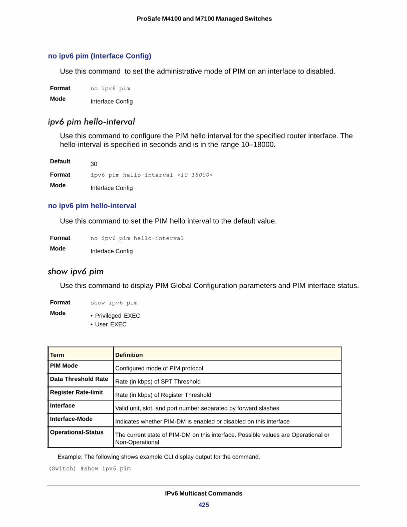
ProSafe M4100 and M7100 Managed Switches
no ipv6 pim (Interface Config)
Use this command to set the administrative mode of PIM on an interface to disabled.
Format no ipv6 pim
Mode
ipv6 pim hello-interval
Use this command to configure the PIM hello interval for the specified router interface. The hello-interval is specified in seconds and is in the range 10–18000.
Default
Format ipv6 pim hello-interval <10-18000>
Mode
no ipv6 pim hello-interval
Use this command to set the PIM hello interval to the default value.
Format no ipv6 pim hello-interval
Mode
show ipv6 pim
Use this command to display PIM Global Configuration parameters and PIM interface status.
Format show ipv6 pim
Mode • Privileged EXEC• User EXEC
Example: The following shows example CLI display output for the command.
(Switch) #show ipv6 pim
Interface Config
30
Interface Config
Interface Config
Term Definition
PIM Mode Configured mode of PIM protocol
Data Threshold Rate Rate (in kbps) of SPT Threshold
Register Rate-limit Rate (in kbps) of Register Threshold
Interface Valid unit, slot, and port number separated by forward slashes
Interface-Mode Indicates whether PIM-DM is enabled or disabled on this interface
Operational-Status The current state of PIM-DM on this interface. Possible values are Operational or Non-Operational.
IPv6 Multicast Commands
425
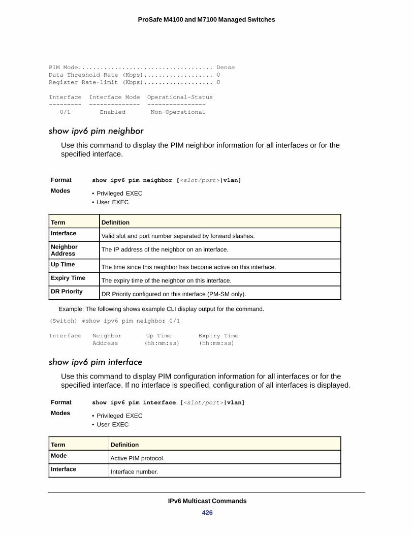
ProSafe M4100 and M7100 Managed Switches
PIM Mode..................................... DenseData Threshold Rate (Kbps)................... 0Register Rate-limit (Kbps)................... 0
Interface Interface Mode Operational-Status--------- -------------- ---------------- 0/1 Enabled Non-Operational
show ipv6 pim neighbor
Use this command to display the PIM neighbor information for all interfaces or for the specified interface.
Example: The following shows example CLI display output for the command.
(Switch) #show ipv6 pim neighbor 0/1
Interface Neighbor Up Time Expiry Time Address (hh:mm:ss) (hh:mm:ss)
show ipv6 pim interface
Use this command to display PIM configuration information for all interfaces or for the specified interface. If no interface is specified, configuration of all interfaces is displayed.
Format show ipv6 pim interface [<slot/port>|vlan]
Modes • Privileged EXEC• User EXEC
Format show ipv6 pim neighbor [<slot/port>|vlan]
Modes • Privileged EXEC• User EXEC
Term Definition
Interface Valid slot and port number separated by forward slashes.
Neighbor Address The IP address of the neighbor on an interface.
Up Time The time since this neighbor has become active on this interface.
Expiry Time The expiry time of the neighbor on this interface.
DR Priority DR Priority configured on this interface (PM-SM only).
Term Definition
Mode Active PIM protocol.
Interface Interface number.
IPv6 Multicast Commands
426
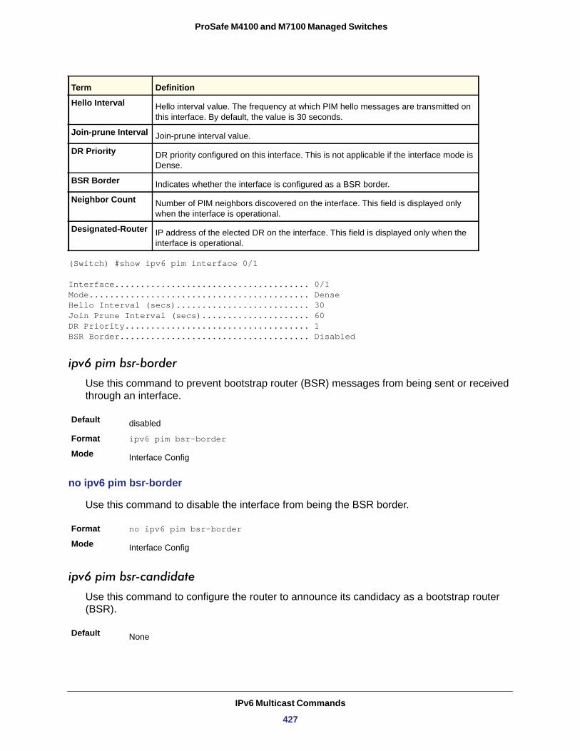
ProSafe M4100 and M7100 Managed Switches
(Switch) #show ipv6 pim interface 0/1
Interface...................................... 0/1Mode........................................... DenseHello Interval (secs).......................... 30Join Prune Interval (secs)..................... 60DR Priority.................................... 1BSR Border..................................... Disabled
ipv6 pim bsr-border
Use this command to prevent bootstrap router (BSR) messages from being sent or received through an interface.
Default
Format ipv6 pim bsr-border
Mode
no ipv6 pim bsr-border
Use this command to disable the interface from being the BSR border.
Format no ipv6 pim bsr-border
Mode
ipv6 pim bsr-candidate
Use this command to configure the router to announce its candidacy as a bootstrap router (BSR).
Hello Interval Hello interval value. The frequency at which PIM hello messages are transmitted on this interface. By default, the value is 30 seconds.
Join-prune Interval Join-prune interval value.
DR Priority DR priority configured on this interface. This is not applicable if the interface mode is Dense.
BSR Border Indicates whether the interface is configured as a BSR border.
Neighbor Count Number of PIM neighbors discovered on the interface. This field is displayed only when the interface is operational.
Designated-Router IP address of the elected DR on the interface. This field is displayed only when the interface is operational.
disabled
Interface Config
Interface Config
Default None
Term Definition
IPv6 Multicast Commands
427
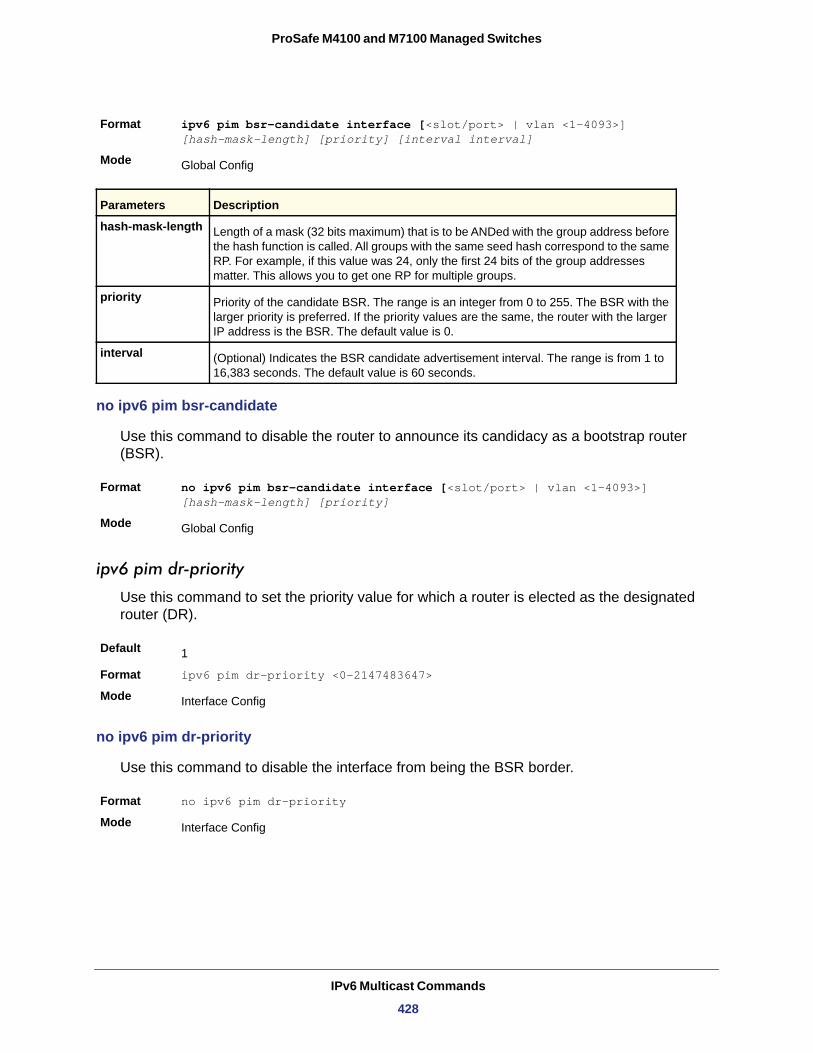
ProSafe M4100 and M7100 Managed Switches
no ipv6 pim bsr-candidate
Use this command to disable the router to announce its candidacy as a bootstrap router (BSR).
Format no ipv6 pim bsr-candidate interface [<slot/port> | vlan <1-4093>] [hash-mask-length] [priority]
Mode
ipv6 pim dr-priority
Use this command to set the priority value for which a router is elected as the designated router (DR).
Default
Format ipv6 pim dr-priority <0-2147483647>
Mode
no ipv6 pim dr-priority
Use this command to disable the interface from being the BSR border.
Format no ipv6 pim dr-priority
Mode
Format ipv6 pim bsr-candidate interface [<slot/port> | vlan <1-4093>] [hash-mask-length] [priority] [interval interval]
Mode
hash-mask-length
priority
interval
Global Config
Parameters Description
Length of a mask (32 bits maximum) that is to be ANDed with the group address before the hash function is called. All groups with the same seed hash correspond to the same RP. For example, if this value was 24, only the first 24 bits of the group addresses matter. This allows you to get one RP for multiple groups.
Priority of the candidate BSR. The range is an integer from 0 to 255. The BSR with the larger priority is preferred. If the priority values are the same, the router with the larger IP address is the BSR. The default value is 0.
(Optional) Indicates the BSR candidate advertisement interval. The range is from 1 to 16,383 seconds. The default value is 60 seconds.
Global Config
1
Interface Config
Interface Config
IPv6 Multicast Commands
428
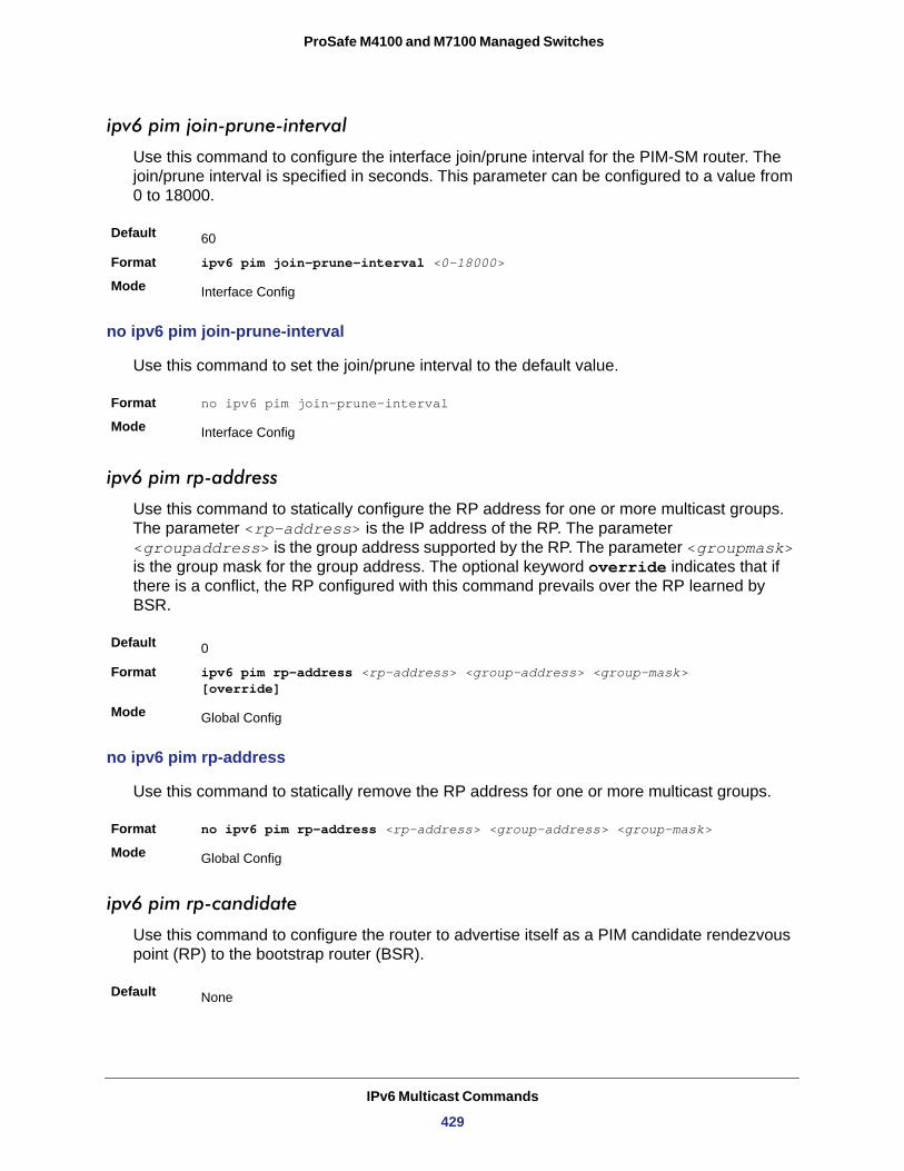
ProSafe M4100 and M7100 Managed Switches
ipv6 pim join-prune-interval
Use this command to configure the interface join/prune interval for the PIM-SM router. The join/prune interval is specified in seconds. This parameter can be configured to a value from 0 to 18000.
Default
Format ipv6 pim join-prune-interval <0-18000>
Mode
no ipv6 pim join-prune-interval
Use this command to set the join/prune interval to the default value.
Format no ipv6 pim join-prune-interval
Mode
ipv6 pim rp-address
Use this command to statically configure the RP address for one or more multicast groups. The parameter <rp-address> is the IP address of the RP. The parameter <groupaddress> is the group address supported by the RP. The parameter <groupmask> is the group mask for the group address. The optional keyword override indicates that if there is a conflict, the RP configured with this command prevails over the RP learned by BSR.
Default
Format ipv6 pim rp-address <rp-address> <group-address> <group-mask> [override]
Mode
no ipv6 pim rp-address
Use this command to statically remove the RP address for one or more multicast groups.
Format no ipv6 pim rp-address <rp-address> <group-address> <group-mask>
Mode
ipv6 pim rp-candidate
Use this command to configure the router to advertise itself as a PIM candidate rendezvous point (RP) to the bootstrap router (BSR).
60
Interface Config
Interface Config
0
Global Config
Global Config
Default None
IPv6 Multicast Commands
429
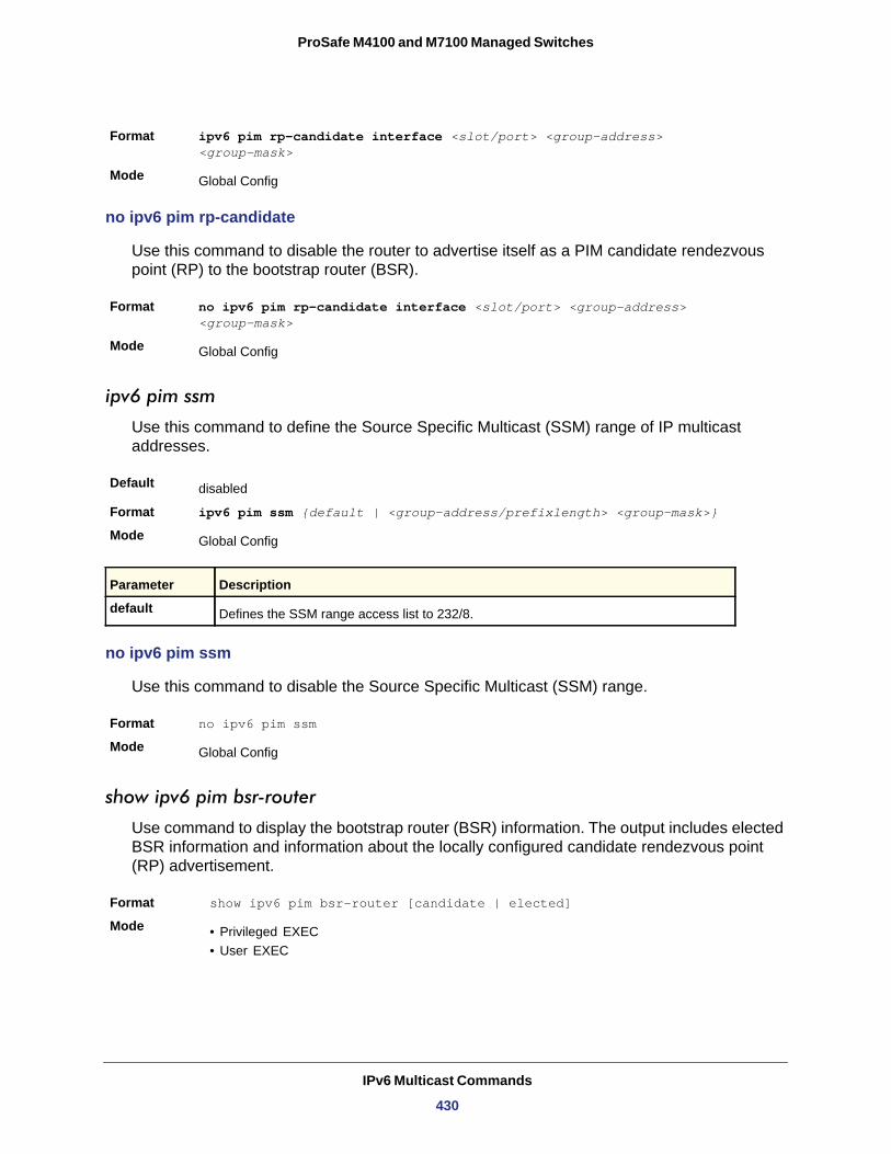
ProSafe M4100 and M7100 Managed Switches
no ipv6 pim rp-candidate
Use this command to disable the router to advertise itself as a PIM candidate rendezvous point (RP) to the bootstrap router (BSR).
Format no ipv6 pim rp-candidate interface <slot/port> <group-address> <group-mask>
Mode
ipv6 pim ssm
Use this command to define the Source Specific Multicast (SSM) range of IP multicast addresses.
Default
Format ipv6 pim ssm {default | <group-address/prefixlength> <group-mask>}
Mode
default
no ipv6 pim ssm
Use this command to disable the Source Specific Multicast (SSM) range.
Format no ipv6 pim ssm
Mode
show ipv6 pim bsr-router
Use command to display the bootstrap router (BSR) information. The output includes elected BSR information and information about the locally configured candidate rendezvous point (RP) advertisement.
Format show ipv6 pim bsr-router [candidate | elected]
Mode • Privileged EXEC• User EXEC
Format ipv6 pim rp-candidate interface <slot/port> <group-address> <group-mask>
Mode Global Config
Global Config
disabled
Global Config
Parameter Description
Defines the SSM range access list to 232/8.
Global Config
IPv6 Multicast Commands
430
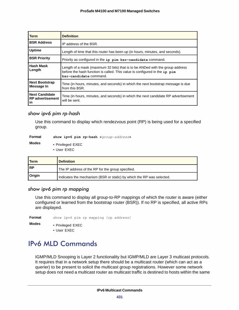
ProSafe M4100 and M7100 Managed Switches
BSR Address
Uptime
BSR Priority
Hash Mask Length
Next Bootstrap Message In
Next Candidate RP advertisement in
show ipv6 pim rp-hash
Use this command to display which rendezvous point (RP) is being used for a specified group.
Format show ipv6 pim rp-hash <group-address>
Modes • Privileged EXEC• User EXEC
RP
Origin
show ipv6 pim rp mapping
Use this command to display all group-to-RP mappings of which the router is aware (either configured or learned from the bootstrap router (BSR)). If no RP is specified, all active RPs are displayed.
Format show ipv6 pim rp mapping [rp address]
Modes • Privileged EXEC• User EXEC
IPv6 MLD Commands
IGMP/MLD Snooping is Layer 2 functionality but IGMP/MLD are Layer 3 multicast protocols. It requires that in a network setup there should be a multicast router (which can act as a querier) to be present to solicit the multicast group registrations. However some network setup does not need a multicast router as multicast traffic is destined to hosts within the same
Term Definition
IP address of the BSR.
Length of time that this router has been up (in hours, minutes, and seconds).
Priority as configured in the ip pim bsr-candidate command.
Length of a mask (maximum 32 bits) that is to be ANDed with the group address before the hash function is called. This value is configured in the ip pim bsr-candidate command.
Time (in hours, minutes, and seconds) in which the next bootstrap message is due from this BSR.
Time (in hours, minutes, and seconds) in which the next candidate RP advertisement will be sent.
Term Definition
The IP address of the RP for the group specified.
Indicates the mechanism (BSR or static) by which the RP was selected.
IPv6 Multicast Commands
431
ProSafe M4100 and M7100 Managed Switches
network. In this situation, the 7000 series has an IGMP/MLD Snooping Querier running on one of the switches and Snooping enabled on all the switches. For more information, see IGMP Snooping Configuration Commands on page 146 and MLD Snooping Commands on page 158.
ipv6 mld router
Use this command, in the administrative mode of the router, to enable MLD in the router.
Default
Format ipv6 mld router
Mode • Global Config• Interface Config
no ipv6 mld router
Use this command, in the administrative mode of the router, to disable MLD in the router.
Default
Format no ipv6 mld router
Mode • Global Config• Interface Config
ipv6 mld query-interval
Use this command to set the MLD router’s query interval for the interface. The query-interval is the amount of time between the general queries sent when the router is the querier on that interface. The range for <query-interval> is 1–3,600 seconds.
Default
Format ipv6 mld query-interval <query-interval>
Mode
no ipv6 mld query-interval
Use this command to reset the MLD query interval to the default value for that interface.
Format no ipv6 mld query-interval
Mode
ipv6 mld query-max-response-time
Use this command to set the MLD querier’s maximum response time for the interface and this value is used in assigning the maximum response time in the query messages that are
Disabled
Disabled
125
Interface Config
Interface Config
IPv6 Multicast Commands
432
ProSafe M4100 and M7100 Managed Switches
sent on that interface. The range for <query-max-response-time> is 0–65,535 milliseconds.
Default
Format ipv6 mld query-max-response-time <query-max-response-time>
Mode
no ipv6 mld query-max-response-time
This command resets the MLD query max response time for the interface to the default value.
Format no ipv6 mld query-max-response-time
Mode
ipv6 mld last-member-query-interval
Use this command to set the last member query interval for the MLD interface, which is the value of the maximum response time parameter in the group-specific queries sent out of this interface. The range for <last-member-query-interval> is 1 - 65,535 milliseconds.
Default
Format ipv6 mld last-member-query-interval <last-member-query-interval>
Mode
no ipv6 mld last-member-query-interval
Use this command to reset the <last-member-query-interval> parameter of the interface to the default value.
Format no ipv6 mld last-member-query-interval
Mode
ipv6 mld last-member-query-count
Use this command to set the number of listener-specific queries sent before the router assumes that there are no local members on the interface. The range for <last-member-query-count> is 1–20.
Default
Format ipv6 mld last-member-query-count <last-member-query-count>
Mode
10000 milliseconds
Interface Config
Interface Config
1000 milliseconds
Interface Config
Interface Config
2
Interface Config
IPv6 Multicast Commands
433
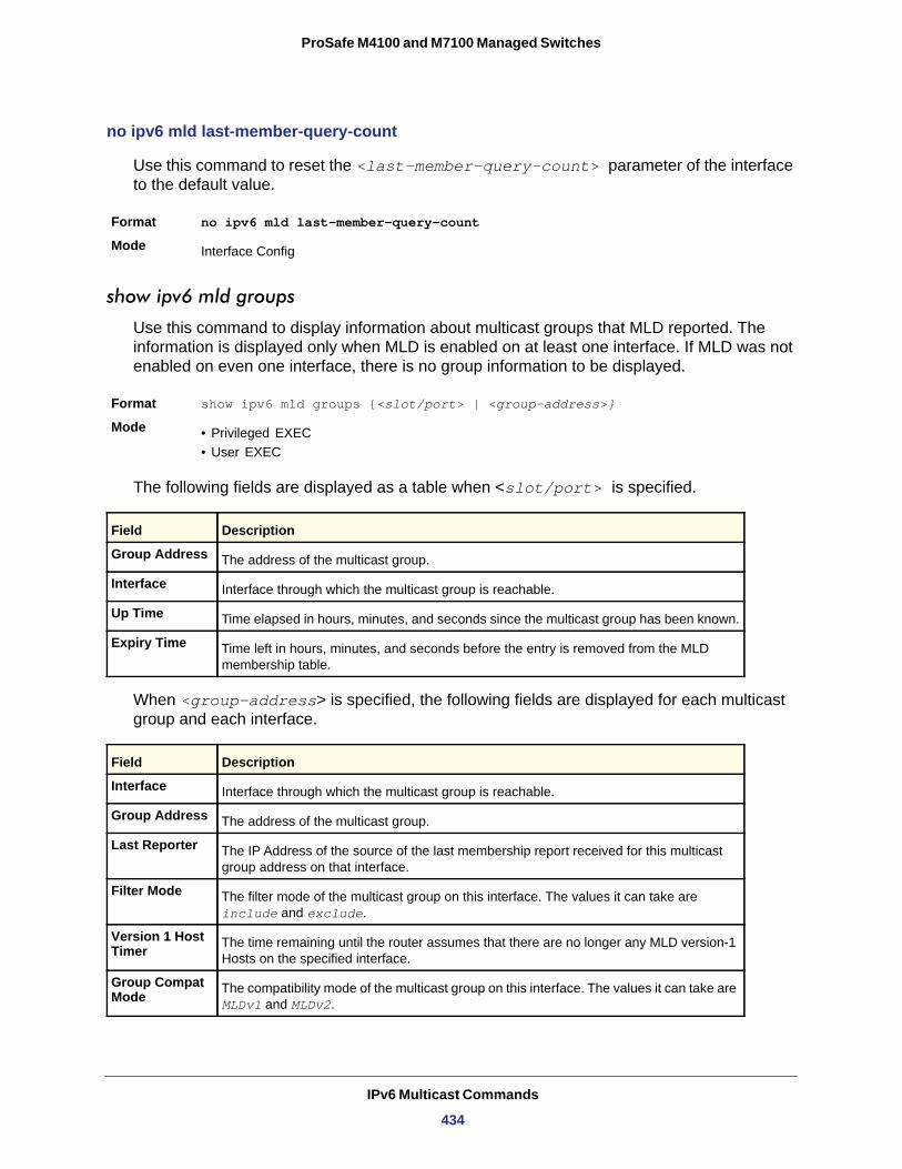
ProSafe M4100 and M7100 Managed Switches
no ipv6 mld last-member-query-count
Use this command to reset the <last-member-query-count> parameter of the interface to the default value.
Format no ipv6 mld last-member-query-count
Mode
show ipv6 mld groups
Use this command to display information about multicast groups that MLD reported. The information is displayed only when MLD is enabled on at least one interface. If MLD was not enabled on even one interface, there is no group information to be displayed.
Format show ipv6 mld groups {<slot/port> | <group-address>}
Mode • Privileged EXEC• User EXEC
Group Address
Interface
Up Time
Expiry Time
The following fields are displayed as a table when <slot/port> is specified.
When <group-address> is specified, the following fields are displayed for each multicast group and each interface.
Interface
Group Address
Last Reporter
Filter Mode
Version 1 Host Timer
Group Compat Mode
Interface Config
Field Description
The address of the multicast group.
Interface through which the multicast group is reachable.
Time elapsed in hours, minutes, and seconds since the multicast group has been known.
Time left in hours, minutes, and seconds before the entry is removed from the MLD membership table.
Field Description
Interface through which the multicast group is reachable.
The address of the multicast group.
The IP Address of the source of the last membership report received for this multicast group address on that interface.
The filter mode of the multicast group on this interface. The values it can take are include and exclude.
The time remaining until the router assumes that there are no longer any MLD version-1 Hosts on the specified interface.
The compatibility mode of the multicast group on this interface. The values it can take are MLDv1 and MLDv2.
IPv6 Multicast Commands
434
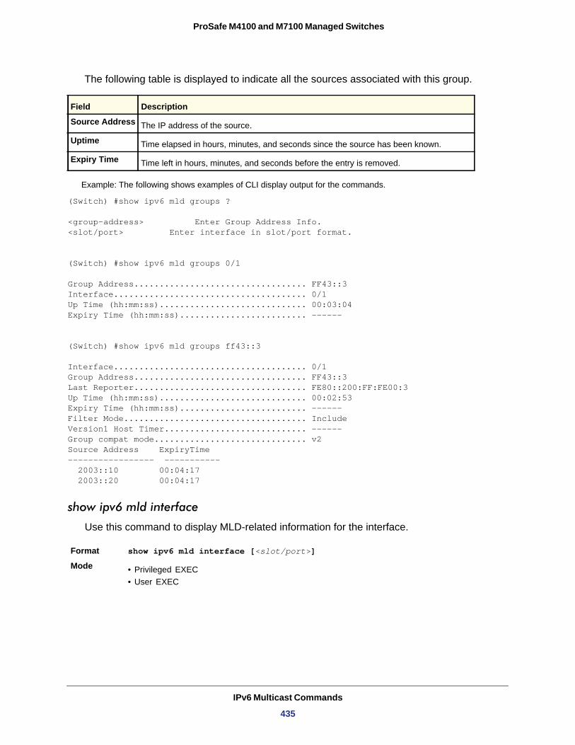
ProSafe M4100 and M7100 Managed Switches
The following table is displayed to indicate all the sources associated with this group.
Source Address
Uptime
Expiry Time
Example: The following shows examples of CLI display output for the commands.
(Switch) #show ipv6 mld groups ?
<group-address> Enter Group Address Info.<slot/port> Enter interface in slot/port format.
(Switch) #show ipv6 mld groups 0/1
Group Address.................................. FF43::3Interface...................................... 0/1Up Time (hh:mm:ss)............................. 00:03:04Expiry Time (hh:mm:ss)......................... ------
(Switch) #show ipv6 mld groups ff43::3
Interface...................................... 0/1Group Address.................................. FF43::3Last Reporter.................................. FE80::200:FF:FE00:3Up Time (hh:mm:ss)............................. 00:02:53Expiry Time (hh:mm:ss)......................... ------Filter Mode.................................... IncludeVersion1 Host Timer............................ ------Group compat mode.............................. v2Source Address ExpiryTime ----------------- ----------- 2003::10 00:04:17 2003::20 00:04:17
show ipv6 mld interface
Use this command to display MLD-related information for the interface.
Format show ipv6 mld interface [<slot/port>]
Mode • Privileged EXEC• User EXEC
Field Description
The IP address of the source.
Time elapsed in hours, minutes, and seconds since the source has been known.
Time left in hours, minutes, and seconds before the entry is removed.
IPv6 Multicast Commands
435
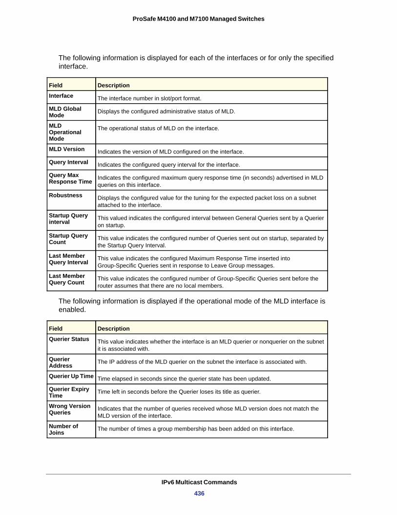
ProSafe M4100 and M7100 Managed Switches
The following information is displayed for each of the interfaces or for only the specified interface.
Interface
MLD Global Mode
MLD Operational Mode
MLD Version
Query Interval
Query Max Response Time
Robustness
Startup Query interval
Startup Query Count
Last Member Query Interval
Last Member Query Count
The following information is displayed if the operational mode of the MLD interface is enabled.
Field Description
The interface number in slot/port format.
Displays the configured administrative status of MLD.
The operational status of MLD on the interface.
Indicates the version of MLD configured on the interface.
Indicates the configured query interval for the interface.
Indicates the configured maximum query response time (in seconds) advertised in MLD queries on this interface.
Displays the configured value for the tuning for the expected packet loss on a subnet attached to the interface.
This valued indicates the configured interval between General Queries sent by a Querier on startup.
This value indicates the configured number of Queries sent out on startup, separated by the Startup Query Interval.
This value indicates the configured Maximum Response Time inserted into Group-Specific Queries sent in response to Leave Group messages.
This value indicates the configured number of Group-Specific Queries sent before the router assumes that there are no local members.
Field Description
Querier Status This value indicates whether the interface is an MLD querier or nonquerier on the subnet it is associated with.
Querier Address The IP address of the MLD querier on the subnet the interface is associated with.
Querier Up Time Time elapsed in seconds since the querier state has been updated.
Querier Expiry Time Time left in seconds before the Querier loses its title as querier.
Wrong Version Queries Indicates that the number of queries received whose MLD version does not match the
MLD version of the interface.
Number of Joins The number of times a group membership has been added on this interface.
IPv6 Multicast Commands
436
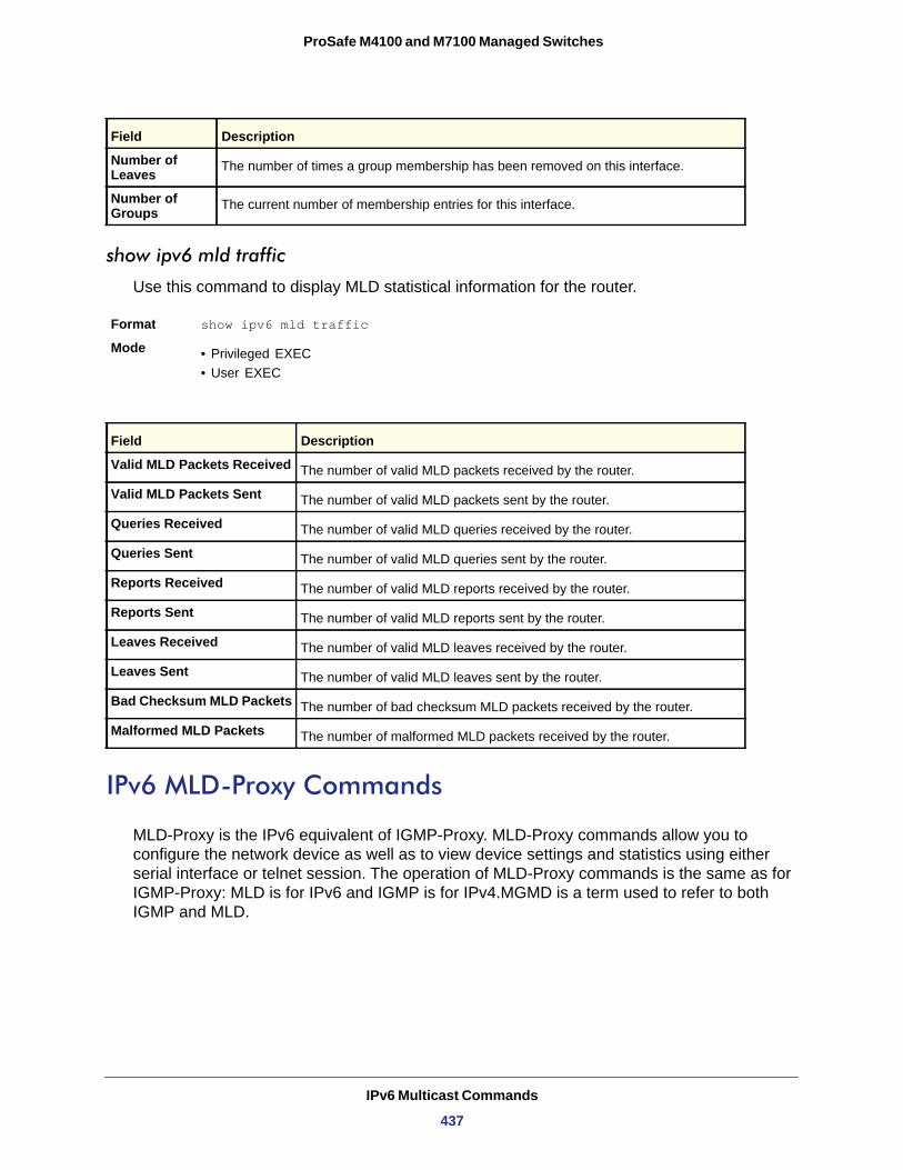
ProSafe M4100 and M7100 Managed Switches
show ipv6 mld traffic
Use this command to display MLD statistical information for the router.
Format show ipv6 mld traffic
Mode • Privileged EXEC• User EXEC
IPv6 MLD-Proxy Commands
MLD-Proxy is the IPv6 equivalent of IGMP-Proxy. MLD-Proxy commands allow you to configure the network device as well as to view device settings and statistics using either serial interface or telnet session. The operation of MLD-Proxy commands is the same as for IGMP-Proxy: MLD is for IPv6 and IGMP is for IPv4.MGMD is a term used to refer to both IGMP and MLD.
Number of Leaves The number of times a group membership has been removed on this interface.
Number of Groups The current number of membership entries for this interface.
Field Description
Valid MLD Packets Received The number of valid MLD packets received by the router.
Valid MLD Packets Sent The number of valid MLD packets sent by the router.
Queries Received The number of valid MLD queries received by the router.
Queries Sent The number of valid MLD queries sent by the router.
Reports Received The number of valid MLD reports received by the router.
Reports Sent The number of valid MLD reports sent by the router.
Leaves Received The number of valid MLD leaves received by the router.
Leaves Sent The number of valid MLD leaves sent by the router.
Bad Checksum MLD Packets The number of bad checksum MLD packets received by the router.
Malformed MLD Packets The number of malformed MLD packets received by the router.
Field Description
IPv6 Multicast Commands
437
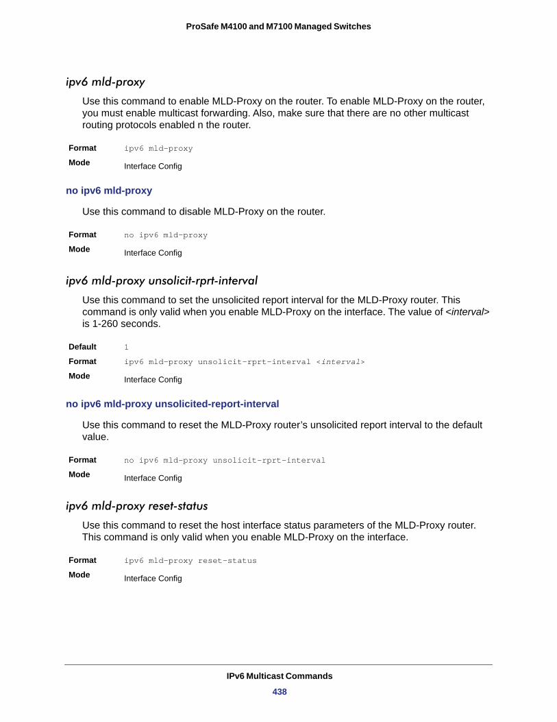
ProSafe M4100 and M7100 Managed Switches
ipv6 mld-proxy
Use this command to enable MLD-Proxy on the router. To enable MLD-Proxy on the router, you must enable multicast forwarding. Also, make sure that there are no other multicast routing protocols enabled n the router.
Format ipv6 mld-proxy
Mode
no ipv6 mld-proxy
Use this command to disable MLD-Proxy on the router.
Format no ipv6 mld-proxy
Mode
ipv6 mld-proxy unsolicit-rprt-interval
Use this command to set the unsolicited report interval for the MLD-Proxy router. This command is only valid when you enable MLD-Proxy on the interface. The value of <interval> is 1-260 seconds.
Default 1
Format ipv6 mld-proxy unsolicit-rprt-interval <interval>
Mode
no ipv6 mld-proxy unsolicited-report-interval
Use this command to reset the MLD-Proxy router’s unsolicited report interval to the default value.
Format no ipv6 mld-proxy unsolicit-rprt-interval
Mode
ipv6 mld-proxy reset-status
Use this command to reset the host interface status parameters of the MLD-Proxy router. This command is only valid when you enable MLD-Proxy on the interface.
Format ipv6 mld-proxy reset-status
Mode
Interface Config
Interface Config
Interface Config
Interface Config
Interface Config
IPv6 Multicast Commands
438
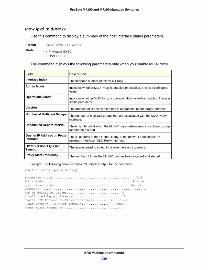
ProSafe M4100 and M7100 Managed Switches
show ipv6 mld-proxy
Use this command to display a summary of the host interface status parameters.
Format show ipv6 mld-proxy
Mode • Privileged EXEC• User EXEC
The command displays the following parameters only when you enable MLD-Proxy.
Interface Index
Admin Mode
Operational Mode
Version
Number of Multicast Groups
Unsolicited Report Interval
Querier IP Address on Proxy Interface
Older Version 1 Querier Timeout
Proxy Start Frequency
Example: The following shows example CLI display output for the command.
(Switch) #show ipv6 mld-proxy
Interface Index............................................. 0/3Admin Mode................................................ EnableOperational Mode......................................... EnableVersion......................................................... 3Num of Multicast Groups............................. 0Unsolicited Report Interval.......................... 1Querier IP Address on Proxy Interface........ fe80::1:2:5Older Version 1 Querier Timeout................ 00:00:00Proxy Start Frequency.................................
Field Description
The interface number of the MLD-Proxy.
Indicates whether MLD-Proxy is enabled or disabled. This is a configured value.
Indicates whether MLD-Proxy is operationally enabled or disabled. This is a status parameter.
The present MLD host version that is operational on the proxy interface.
The number of multicast groups that are associated with the MLD-Proxy interface.
The time interval at which the MLD-Proxy interface sends unsolicited group membership report.
The IP address of the Querier, if any, in the network attached to the upstream interface (MLD-Proxy interface).
The interval used to timeout the older version 1 queriers.
The number of times the MLD-Proxy has been stopped and started.
IPv6 Multicast Commands
439
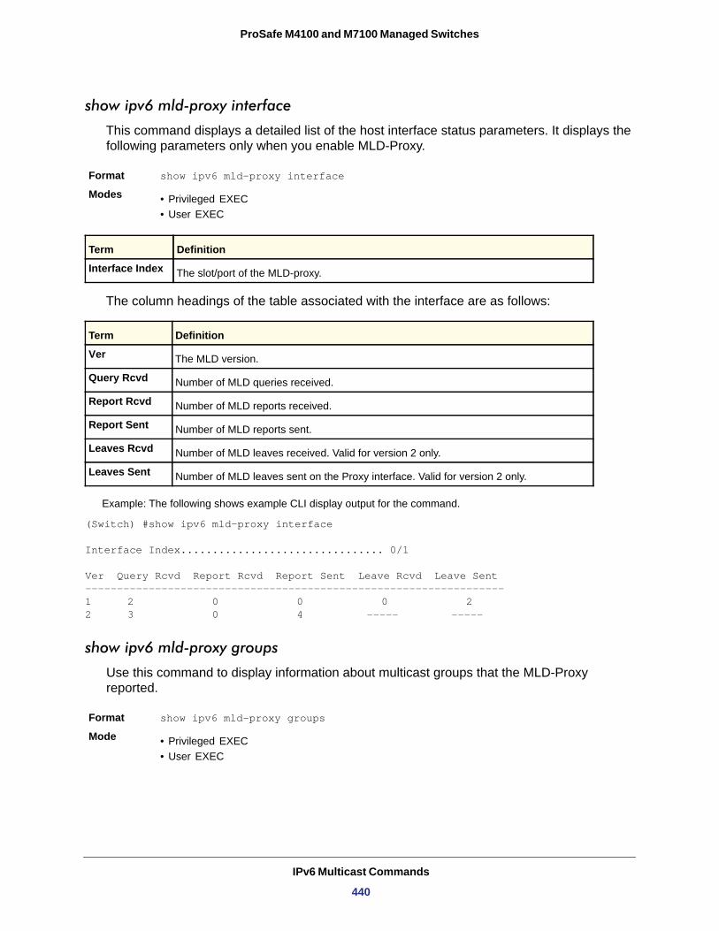
ProSafe M4100 and M7100 Managed Switches
show ipv6 mld-proxy interface
This command displays a detailed list of the host interface status parameters. It displays the following parameters only when you enable MLD-Proxy.
Format show ipv6 mld-proxy interface
Modes • Privileged EXEC• User EXEC
Interface Index
The column headings of the table associated with the interface are as follows:
Ver
Query Rcvd
Report Rcvd
Report Sent
Leaves Rcvd
Leaves Sent
Example: The following shows example CLI display output for the command.
(Switch) #show ipv6 mld-proxy interface
Interface Index................................ 0/1
Ver Query Rcvd Report Rcvd Report Sent Leave Rcvd Leave Sent------------------------------------------------------------------1 2 0 0 0 22 3 0 4 ----- -----
show ipv6 mld-proxy groups
Use this command to display information about multicast groups that the MLD-Proxy reported.
Format show ipv6 mld-proxy groups
Mode • Privileged EXEC• User EXEC
Term Definition
The slot/port of the MLD-proxy.
Term Definition
The MLD version.
Number of MLD queries received.
Number of MLD reports received.
Number of MLD reports sent.
Number of MLD leaves received. Valid for version 2 only.
Number of MLD leaves sent on the Proxy interface. Valid for version 2 only.
IPv6 Multicast Commands
440
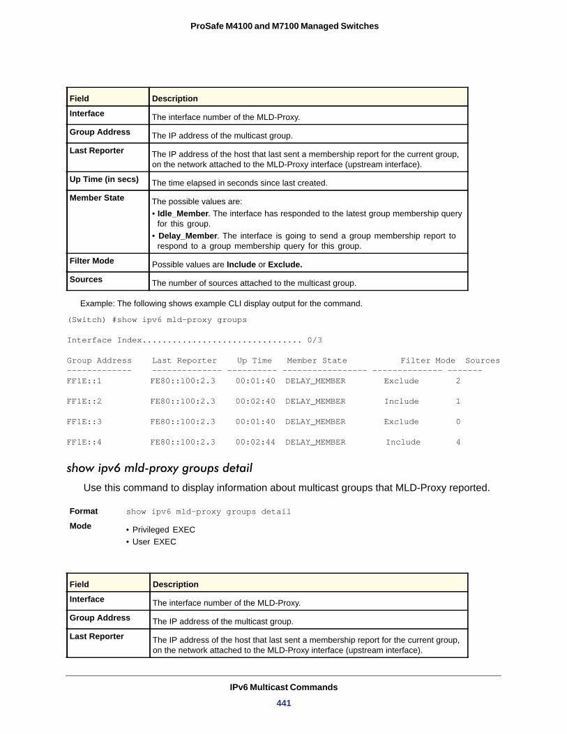
ProSafe M4100 and M7100 Managed Switches
Example: The following shows example CLI display output for the command.
(Switch) #show ipv6 mld-proxy groups
Interface Index................................ 0/3
Group Address Last Reporter Up Time Member State Filter Mode Sources------------- -------------- ---------- ----------------- -------------- -------FF1E::1 FE80::100:2.3 00:01:40 DELAY_MEMBER Exclude 2
FF1E::2 FE80::100:2.3 00:02:40 DELAY_MEMBER Include 1
FF1E::3 FE80::100:2.3 00:01:40 DELAY_MEMBER Exclude 0
FF1E::4 FE80::100:2.3 00:02:44 DELAY_MEMBER Include 4
show ipv6 mld-proxy groups detail
Use this command to display information about multicast groups that MLD-Proxy reported.
Format show ipv6 mld-proxy groups detail
Mode • Privileged EXEC• User EXEC
Field Description
Interface The interface number of the MLD-Proxy.
Group Address The IP address of the multicast group.
Last Reporter The IP address of the host that last sent a membership report for the current group, on the network attached to the MLD-Proxy interface (upstream interface).
Up Time (in secs) The time elapsed in seconds since last created.
Member State The possible values are:• Idle_Member. The interface has responded to the latest group membership query
for this group.• Delay_Member. The interface is going to send a group membership report to
respond to a group membership query for this group.
Filter Mode Possible values are Include or Exclude.
Sources The number of sources attached to the multicast group.
Field Description
Interface The interface number of the MLD-Proxy.
Group Address The IP address of the multicast group.
Last Reporter The IP address of the host that last sent a membership report for the current group, on the network attached to the MLD-Proxy interface (upstream interface).
IPv6 Multicast Commands
441
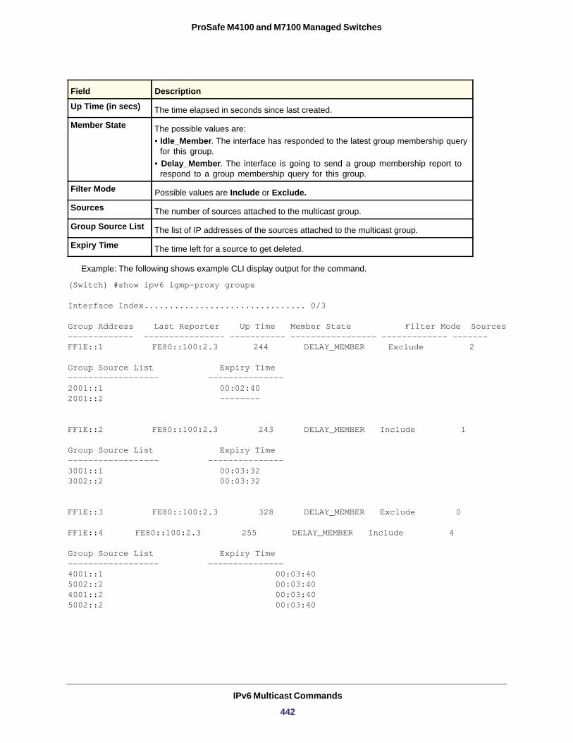
ProSafe M4100 and M7100 Managed Switches
Example: The following shows example CLI display output for the command.
(Switch) #show ipv6 igmp-proxy groups
Interface Index................................ 0/3
Group Address Last Reporter Up Time Member State Filter Mode Sources------------- ---------------- ----------- ----------------- ------------- -------FF1E::1 FE80::100:2.3 244 DELAY_MEMBER Exclude 2
Group Source List Expiry Time------------------ ---------------2001::1 00:02:402001::2 --------
FF1E::2 FE80::100:2.3 243 DELAY_MEMBER Include 1
Group Source List Expiry Time------------------ ---------------3001::1 00:03:323002::2 00:03:32
FF1E::3 FE80::100:2.3 328 DELAY_MEMBER Exclude 0
FF1E::4 FE80::100:2.3 255 DELAY_MEMBER Include 4
Group Source List Expiry Time------------------ ---------------4001::1 00:03:405002::2 00:03:404001::2 00:03:405002::2 00:03:40
Up Time (in secs) The time elapsed in seconds since last created.
Member State The possible values are:• Idle_Member. The interface has responded to the latest group membership query
for this group.• Delay_Member. The interface is going to send a group membership report to
respond to a group membership query for this group.
Filter Mode Possible values are Include or Exclude.
Sources The number of sources attached to the multicast group.
Group Source List The list of IP addresses of the sources attached to the multicast group.
Expiry Time The time left for a source to get deleted.
Field Description
IPv6 Multicast Commands
442
8
8. Quality of Service (QoS) CommandsThis chapter describes the Quality of Service (QoS) commands available in the managed switch CLI.
This chapter contains the following sections:
• Class of Service (CoS) Commands • Differentiated Services (DiffServ) Commands • DiffServ Class Commands • DiffServ Policy Commands • DiffServ Service Commands • DiffServ Show Commands • MAC Access Control List (ACL) Commands • IP Access Control List (ACL) Commands • IPv6 Access Control List (ACL) Commands • Time Range Commands for Time-Based ACLs • AutoVOIP • iSCSI Commands
The commands in this chapter are in two functional groups:
• Show commands display switch settings, statistics, and other information.• Configuration commands configure features and options of the switch. Every switch
command has a show command that displays the configuration setting.
443
ProSafe M4100 and M7100 Managed Switches
Class of Service (CoS) Commands
This section describes the commands you use to configure and view Class of Service (CoS) settings for the switch. The commands in this section allow you to control the priority and transmission rate of traffic.
Note: Commands you issue in the Interface Config mode only affect a single interface. Commands you issue in the Global Config mode affect all interfaces.
classofservice dot1p-mapping
This command maps an 802.1p priority to an internal traffic class. The <userpriority> values can range from 0-7. The <trafficclass> values range from 0-6, although the actual number of available traffic classes depends on the platform. For more information about 802.1p priority, see Voice VLAN Commands on page 62
Format classofservice dot1p-mapping <userpriority> <trafficclass>
Modes • Global Config• Interface Config
.
no classofservice dot1p-mapping
This command maps each 802.1p priority to its default internal traffic class value.
Format no classofservice dot1p-mapping
Modes • Global Config• Interface Config
classofservice ip-dscp-mapping
This command maps an IP DSCP value to an internal traffic class. The <ipdscp> value is specified as either an integer from 0 to 63, or symbolically through one of the following keywords: af11, af12, af13, af21, af22, af23, af31, af32, af33, af41, af42, af43, be, cs0, cs1, cs2, cs3, cs4, cs5, cs6, cs7, ef.
The <trafficclass> values can range from 0-6, although the actual number of available traffic classes depends on the platform.
Format classofservice ip-dscp-mapping <ipdscp> <trafficclass>
Modes Global Config
Quality of Service (QoS) Commands
444
ProSafe M4100 and M7100 Managed Switches
no classofservice ip-dscp-mapping
This command maps each IP DSCP value to its default internal traffic class value.
Format no classofservice ip-dscp-mapping
Modes
classofservice trust
This command sets the Class of Service trust mode of an interface. You can set the mode to trust one of the Dot1p (802.1p), IP DSCP, or IP Precedence packet markings. You can also set the interface mode to untrusted. If you configure an interface to use Dot1p, the mode does not appear in the output of the show running config command because Dot1p is the default.
Default
Format classofservice trust {dot1p | ip-dscp | ip-precedence | untrusted}
Modes • Global Config• Interface Config
no classofservice trust
This command sets the interface mode to the default value.
Format no classofservice trust
Modes • Global Config• Interface Config
cos-queue min-bandwidth
This command specifies the minimum transmission bandwidth guarantee for each interface queue. The total number of queues supported per interface is platform-specific. A value from 0–100 (percentage of link rate) must be specified for each supported queue, with 0 indicating no guaranteed minimum bandwidth. The sum of all values entered must not exceed 100.
Format cos-queue min-bandwidth <bw-0> <bw-1> … <bw-n>
Modes • Global Config• Interface Config
no cos-queue min-bandwidth
This command restores the default for each queue's minimum bandwidth value.
Format no cos-queue min-bandwidth
Modes • Global Config• Interface Config
Global Config
dot1p
Quality of Service (QoS) Commands
445
ProSafe M4100 and M7100 Managed Switches
cos-queue strict
This command activates the strict priority scheduler mode for each specified queue.
Format cos-queue strict <queue-id-1> [<queue-id-2> … <queue-id-n>]
Modes • Global Config• Interface Config
no cos-queue strict
This command restores the default weighted scheduler mode for each specified queue.
Format no cos-queue strict <queue-id-1> [<queue-id-2> … <queue-id-n>]
Modes • Global Config• Interface Config
cos-queue random-detect
This command activates weighted random early discard (WRED) for each specified queue on the interface. Specific WRED parameters are configured using the randomdetect queue-parms and the random-detect exponential-weighting-constant commands. When specified in Interface Config' mode, this command affects a single interface only, whereas in Global Config mode, it applies to all interfaces. At least one, but no more than n, queue-id values are specified with this command.
Duplicate queue-id values are ignored. Each queue-id value ranges from 0 to (n-1), where n is the total number of queues supported per interface. The number n is platform dependant and corresponds to the number of supported queues (traffic classes).
Format cos-queue random-detect queue-id-1 [queue-id-2 … queue-id-n]
Modes • Global Config• Interface Config
no cos-queue random-detect
Use this command to disable WRED and restore the default tail drop operation for the specified queues on all interfaces or one interface.
Format cos-queue random-detect queue-id-1 [queue-id-2 … queue-id-n]
Modes • Global Config• Interface Config
Quality of Service (QoS) Commands
446
ProSafe M4100 and M7100 Managed Switches
random-detect exponential weighting-constant
Use this command to configure the WRED decay exponent for a CoS queue interface.
Format random-detect exponential-weighting-constant 0-15
Modes • Global Config• Interface Config
Default
no random-detect exponential weighting-constant
Use this command to reset the WRED decay exponent to the default value on all interfaces or one interface.
Format no random-detect exponential-weighting-constant 0-15
Modes • Global Config• Interface Config
random-detect queue-parms
Use this command to configure WRED parameters for each drop precedence level supported by a queue. Use it only when per-COS queue configuration is enabled (using the cos-queue random-detect command).
min-thresh is the minimum threshold the queue depth (as a percentage) where WRED starts marking and dropping traffic.
max-thresh is the maximum threshold is the queue depth (as a percentage) above which WRED marks / drops all traffic.
drop-probability is the percentage probability that WRED will mark/drop a packet, when the queue depth is at the maximum threshold. (The drop probability increases linearly from 0 just before the minimum threshold, to this value at the maximum threshold, then goes to 100% for larger queue depths). Each parameter is specified for each possible drop precedence ("color" of TCP traffic).
The last precedence applies to all non-TCP traffic. For example, in a 3-color system, four of each parameter specified: green TCP, yellow TCP, red TCP, and non-TCP, respectively.
Format random-detect queue-parms queue-id-1 [queue-id-2 … queue-id-n] minthresh thresh-prec-1 … thresh-prec-n max-thresh thresh-prec-1 … threshprec-n drop-probability prob-prec-1 … prob-prec-n
Modes • Global Config• Interface Config
9
Quality of Service (QoS) Commands
447
ProSafe M4100 and M7100 Managed Switches
no random-detect queue-parms
Use this command to set the WRED configuration back to the default.
Format no random-detect queue-parms queue-id-1 [queue-id-2 … queue-id-n]
Modes • Global Config• Interface Config
traffic-shape
This command specifies the maximum transmission bandwidth limit for the interface as a whole. Also known as rate shaping, traffic shaping has the effect of smoothing temporary traffic bursts over time so that the transmitted traffic rate is bounded.
Format traffic-shape <bw>
Modes • Global Config• Interface Config
no traffic-shape
This command restores the interface shaping rate to the default value.
Format no traffic-shape
Modes • Global Config• Interface Config
show classofservice dot1p-mapping
This command displays the current Dot1p (802.1p) priority mapping to internal traffic classes for a specific interface. The <slot/port> parameter is optional and is only valid on platforms that support independent per-port Class of Service mappings. If specified, the 802.1p mapping table of the interface is displayed. If omitted, the most recent global configuration settings are displayed. For more information, see Voice VLAN Commands on page 62.
Format show classofservice dot1p-mapping [<slot/port>]
Mode
The following information is repeated for each user priority.
User Priority
Traffic Class
Privileged EXEC
Term Definition
The 802.1p user priority value.
The traffic class internal queue identifier to which the user priority value is mapped.
Quality of Service (QoS) Commands
448
ProSafe M4100 and M7100 Managed Switches
show classofservice ip-precedence-mapping
This command displays the current IP Precedence mapping to internal traffic classes for a specific interface. The slot/port parameter is optional and is only valid on platforms that support independent per-port Class of Service mappings. If specified, the IP Precedence mapping table of the interface is displayed. If omitted, the most recent global configuration settings are displayed.
Format show classofservice ip-precedence-mapping [<slot/port>]
Mode
The following information is repeated for each user priority.
IP Precedence
Traffic Class
show classofservice ip-dscp-mapping
This command displays the current IP DSCP mapping to internal traffic classes for the global configuration settings.
Format show classofservice ip-dscp-mapping
Mode
The following information is repeated for each user priority.
IP DSCP
Traffic Class
show classofservice trust
This command displays the current trust mode setting for a specific interface. The <slot/port> parameter is optional and is only valid on platforms that support independent per-port Class of Service mappings. If you specify an interface, the command displays the port trust mode of the interface. If you do not specify an interface, the command displays the most recent global configuration settings.
Format show classofservice trust [<slot/port>]
Mode
Privileged EXEC
Term Definition
The IP Precedence value.
The traffic class internal queue identifier to which the IP Precedence value is mapped.
Privileged EXEC
Term Definition
The IP DSCP value.
The traffic class internal queue identifier to which the IP DSCP value is mapped.
Privileged EXEC
Quality of Service (QoS) Commands
449
ProSafe M4100 and M7100 Managed Switches
Non-IP Traffic Class
Untrusted Traffic Class
show interfaces cos-queue
This command displays the class-of-service queue configuration for the specified interface. The slot/port parameter is optional and is only valid on platforms that support independent per-port Class of Service mappings. If specified, the class-of-service queue configuration of the interface is displayed. If omitted, the most recent global configuration settings are displayed.
Format show interfaces cos-queue [<slot/port>]
Mode
Queue Id
Minimum Bandwidth
Scheduler Type
Queue Management Type
If you specify the interface, the command also displays the following information.
Interface
Interface Shaping Rate
Term Definition
The traffic class used for non-IP traffic. This is only displayed when the COS trust mode is set to trust IP Precedence or IP DSCP (on platforms that support IP DSCP).
The traffic class used for all untrusted traffic. This is only displayed when the COS trust mode is set to 'untrusted'.
Privileged EXEC
Term Definition
An interface supports n queues numbered 0 to (n-1). The specific n value is platform-dependent.
The minimum transmission bandwidth guarantee for the queue, expressed as a percentage. A value of 0 means bandwidth is not guaranteed and the queue operates using best-effort. This is a configured value.
Indicates whether this queue is scheduled for transmission using a strict priority or a weighted scheme. This is a configured value.
The queue depth management technique used for this queue (tail drop).
Term Definition
The slot/port of the interface. If displaying the global configuration, this output line is replaced with a Global Config indication.
The maximum transmission bandwidth limit for the interface as a whole. It is independent of any per-queue maximum bandwidth value(s) in effect for the interface. This is a configured value.
Quality of Service (QoS) Commands
450
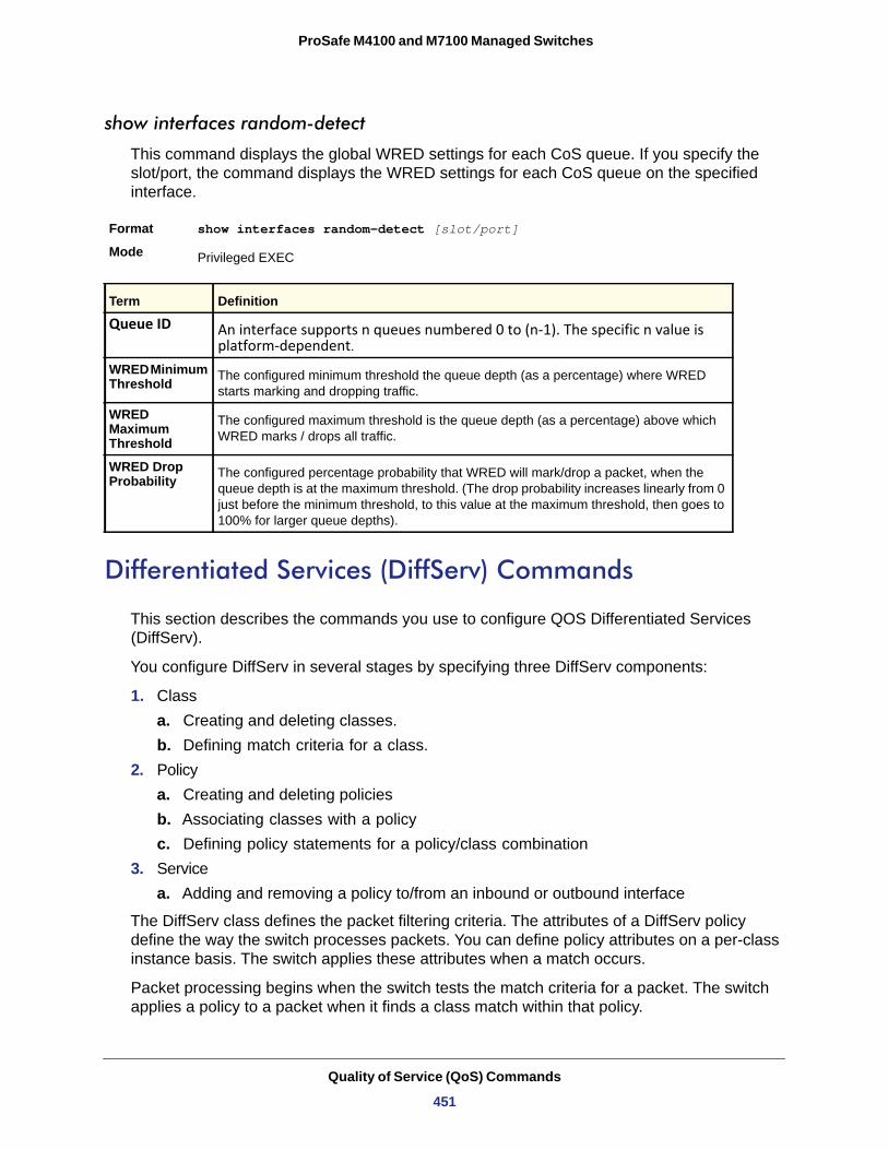
ProSafe M4100 and M7100 Managed Switches
show interfaces random-detect
This command displays the global WRED settings for each CoS queue. If you specify the slot/port, the command displays the WRED settings for each CoS queue on the specified interface.
Format show interfaces random-detect [slot/port]
Mode
Queue ID
WRED Minimum Threshold
WRED Maximum Threshold
WRED Drop Probability
Differentiated Services (DiffServ) Commands
This section describes the commands you use to configure QOS Differentiated Services (DiffServ).
You configure DiffServ in several stages by specifying three DiffServ components:
1. Classa. Creating and deleting classes.b. Defining match criteria for a class.
2. Policya. Creating and deleting policiesb. Associating classes with a policyc. Defining policy statements for a policy/class combination
3. Servicea. Adding and removing a policy to/from an inbound or outbound interface
The DiffServ class defines the packet filtering criteria. The attributes of a DiffServ policy define the way the switch processes packets. You can define policy attributes on a per-class instance basis. The switch applies these attributes when a match occurs.
Packet processing begins when the switch tests the match criteria for a packet. The switch applies a policy to a packet when it finds a class match within that policy.
Privileged EXEC
Term Definition
An interface supports n queues numbered 0 to (n-1). The specific n value is platform-dependent.
The configured minimum threshold the queue depth (as a percentage) where WRED starts marking and dropping traffic.
The configured maximum threshold is the queue depth (as a percentage) above which WRED marks / drops all traffic.
The configured percentage probability that WRED will mark/drop a packet, when the queue depth is at the maximum threshold. (The drop probability increases linearly from 0 just before the minimum threshold, to this value at the maximum threshold, then goes to 100% for larger queue depths).
Quality of Service (QoS) Commands
451
ProSafe M4100 and M7100 Managed Switches
The following rules apply when you create a DiffServ class:
• Each class can contain a maximum of one referenced (nested) class• Class definitions do not support hierarchical service policies
A given class definition can contain a maximum of one reference to another class. You can combine the reference with other match criteria. The referenced class is truly a reference and not a copy, because additions to a referenced class affect all classes that reference it. Changes to any class definition currently referenced by any other class must result in valid class definitions for all derived classes, otherwise the switch rejects the change. You can remove a class reference from a class definition.
The only way to remove an individual match criterion from an existing class definition is to delete the class and re-create it.
Note: The mark possibilities for policing include CoS, IP DSCP, and IP Precedence. While the latter two are only meaningful for IP packet types, CoS marking is allowed for both IP and non-IP packets, since it updates the 802.1p user priority field contained in the VLAN tag of the layer 2 packet header.
diffserv
This command sets the DiffServ operational mode to active. While disabled, the DiffServ configuration is retained and can be changed, but it is not activated. When enabled, DiffServ services are activated.
Format diffserv
Mode
no diffserv
This command sets the DiffServ operational mode to inactive. While disabled, the DiffServ configuration is retained and can be changed, but it is not activated. When enabled, DiffServ services are activated.
Format no diffserv
Mode
DiffServ Class Commands
Use the DiffServ class commands to define traffic classification. To classify traffic, you specify Behavior Aggregate (BA), based on DSCP and Multi-Field (MF) classes of traffic (name, match criteria)
Global Config
Global Config
Quality of Service (QoS) Commands
452
ProSafe M4100 and M7100 Managed Switches
This set of commands consists of class creation/deletion and matching, with the class match commands specifying Layer 3, Layer 2, and general match criteria. The class match criteria are also known as class rules, with a class definition consisting of one or more rules to identify the traffic that belongs to the class.
Note: Once you create a class match criterion for a class, you cannot change or delete the criterion. To change or delete a class match criterion, you must delete and re-create the entire class.
The CLI command root is class-map.
class-map
This command defines a DiffServ class of type match-all. When used without any match condition, this command enters the class-map mode. The <class-map-name> is a case-sensitive alphanumeric string from 1 to 31 characters uniquely identifying an existing DiffServ class.
Note: The class-map-name default is reserved and must not be used.
The class type of match-all indicates all of the individual match conditions must be true for a packet to be considered a member of the class. This command might be used without specifying a class type to enter the Class-Map Config mode for an existing DiffServ class.
Note: The optional keywords [{ipv4 | ipv6}] specify the Layer 3 protocol for this class. If not specified, this parameter defaults to ipv4. This maintains backward compatibility for configurations defined on systems before IPv6 match items were supported.
Note: The CLI mode is changed to Class-Map Config or Ipv6-Class-Map Config when this command is successfully executed depending on the [{ipv4 | ipv6}] keyword specified.
Format class-map match-all <class-map-name> [{ipv4 | ipv6}]
Mode Global Config
Quality of Service (QoS) Commands
453
ProSafe M4100 and M7100 Managed Switches
no class-map
This command eliminates an existing DiffServ class. The <class-map-name> is the name of an existing DiffServ class. (The class name ‘default’ is reserved and is not allowed here.) This command might be issued at any time; if the class is currently referenced by one or more policies or by any other class, the delete action fails.
Format no class-map <class-map-name>
Mode
class-map rename
This command changes the name of a DiffServ class. The <class-map-name> is the name of an existing DiffServ class. The <new-class-map-name> parameter is a case-sensitive alphanumeric string from 1 to 31 characters uniquely identifying the class.
Default
Format class-map rename <class-map-name> <new-class-map-name>
Mode
match ethertype
This command adds to the specified class definition a match condition based on the value of the ethertype. The <ethertype> value is specified as one of the following keywords: appletalk, arp, ibmsna, ipv4, ipv6, ipx, mplsmcast, mplsucast, netbios, novell, pppoe, rarp or as a custom ethertype value in the range of 0x0600-0xFFFF.
Format match ethertype {<keyword> | custom <0x0600-0xFFFF>}
Mode
match any
This command adds to the specified class definition a match condition whereby all packets are considered to belong to the class.
Default
Format match any
Mode
Global Config
none
Global Config
Class-Map Config Ipv6-Class-Map Config
none
Class-Map Config Ipv6-Class-Map Config
Quality of Service (QoS) Commands
454
ProSafe M4100 and M7100 Managed Switches
match class-map
This command adds to the specified class definition the set of match conditions defined for another class. The <refclassname> is the name of an existing DiffServ class whose match conditions are being referenced by the specified class definition.
Default none
Format match class-map <refclassname>
Mode
Note the following:
• The parameters <refclassname> and <class-map-name> cannot be the same.• Only one other class might be referenced by a class.• Any attempts to delete the <refclassname> class while the class is still referenced by any
<class-map-name> fails. • The combined match criteria of <class-map-name> and <refclassname> must be an
allowed combination based on the class type. • Any subsequent changes to the <refclassname> class match criteria must maintain this
validity, or the change attempt fails.• The total number of class rules formed by the complete reference class chain (including
both predecessor and successor classes) must not exceed a platform-specific maximum. In some cases, each removal of a refclass rule reduces the maximum number of available rules in the class definition by one.
no match class-map
This command removes from the specified class definition the set of match conditions defined for another class. The <refclassname> is the name of an existing DiffServ class whose match conditions are being referenced by the specified class definition.
Format no match class-map <refclassname>
Mode
match cos
This command adds to the specified class definition a match condition for the Class of Service value (the only tag in a single tagged packet or the first or outer 802.1Q tag of a double VLAN tagged packet). The value might be from 0 to 7.
Default
Format match cos <0-7>
Mode
Class-Map Config Ipv6-Class-Map Config
Class-Map Config Ipv6-Class-Map Config
none
Class-Map Config Ipv6-Class-Map Config
Quality of Service (QoS) Commands
455
ProSafe M4100 and M7100 Managed Switches
match secondary cos
This command adds to the specified class definition a match condition for the secondary Class of Service value (the only tag in a single tagged packet or the first or outer 802.1Q tag of a double VLAN tagged packet). The value might be from 0 to 7.
Default
Format match secondary-cos <0-7>
Mode
match ip6flowlbl
This command adds to the specified class definition a match condition based on the IP6flowlbl of a packet. The label is the value to match in the Flow Label field of the IPv6 header (range 0-1048575).
Format match ip6flowlbl <label>
Mode
match destination-address mac
This command adds to the specified class definition a match condition based on the destination MAC address of a packet. The <macaddr> parameter is any layer 2 MAC address formatted as six, two-digit hexadecimal numbers separated by colons (for example, 00:11:22:dd:ee:ff). The <macmask> parameter is a layer 2 MAC address bit mask, which need not to be contiguous, and is formatted as six, two-digit hexadecimal numbers separated by colons (for example, ff:07:23:ff:fe:dc).
Default
Format match destination-address mac <macaddr> <macmask>
Mode
match dstip
This command adds to the specified class definition a match condition based on the destination IP address of a packet. The <ipaddr> parameter specifies an IP address. The <ipmask> parameter specifies an IP address bit mask and must consist of a contiguous set of leading 1 bits.
Default
Format match dstip <ipaddr> <ipmask>
Mode
none
Class-Map Config
Ipv6-Class-Map Configuration mode
none
Class-Map ConfigIpv6-Class-Map Config
none
Class-Map Config
Quality of Service (QoS) Commands
456
ProSafe M4100 and M7100 Managed Switches
match dstip6
This command adds to the specified class definition a match condition based on the destination IPv6 address of a packet.
Default
Format match dstip6 <destination-ipv6-prefix/prefix-length>
Mode
match dstl4port
This command adds to the specified class definition a match condition based on the destination layer 4 port of a packet using a single keyword or numeric notation. To specify the match condition as a single keyword, the value for <portkey> is one of the supported port name keywords. The currently supported <portkey> values are: domain, echo, ftp, ftpdata, http, smtp, snmp, telnet, tftp, www. Each of these translates into its equivalent port number. To specify the match condition using a numeric notation, one layer 4-port number is required. The port number is an integer from 0 to 65535.
Default
Format match dstl4port {<portkey> | <0-65535>}
Mode
match ip dscp
This command adds to the specified class definition a match condition based on the value of the IP DiffServ Code Point (DSCP) field in a packet, which is defined as the high-order six bits of the Service Type octet in the IP header (the low-order two bits are not checked).
The <dscpval> value is specified as either an integer from 0 to 63, or symbolically through one of the following keywords: af11, af12, af13, af21, af22, af23, af31, af32, af33, af41, af42, af43, be, cs0, cs1, cs2, cs3, cs4, cs5, cs6, cs7, ef.
Note: The ip dscp, ip precedence, and ip tos match conditions are alternative ways to specify a match criterion for the same Service Type field in the IP header, but with a slightly different user notation.
none
Ipv6-Class-Map Config
none
Class-Map ConfigIpv6-Class-Map Config
Default none
Format match ip dscp <dscpval>
Mode Class-Map ConfigIpv6-Class-Map Config
Quality of Service (QoS) Commands
457
ProSafe M4100 and M7100 Managed Switches
match ip precedence
This command adds to the specified class definition a match condition based on the value of the IP Precedence field in a packet, which is defined as the high-order three bits of the Service Type octet in the IP header (the low-order five bits are not checked). The precedence value is an integer from 0 to 7.
Note: The IP DSCP, IP Precedence, and IP ToS match conditions are alternative ways to specify a match criterion for the same Service Type field in the IP header, but with a slightly different user notation.
match ip tos
This command adds to the specified class definition a match condition based on the value of the IP TOS field in a packet, which is defined as all eight bits of the Service Type octet in the IP header. The value of <tosbits> is a two-digit hexadecimal number from 00 to ff. The value of <tosmask> is a two-digit hexadecimal number from 00 to ff. The <tosmask> denotes the bit positions in <tosbits> that are used for comparison against the IP TOS field in a packet. For example, to check for an IP TOS value having bits 7 and 5 set and bit 1 clear, where bit 7 is most significant, use a <tosbits> value of a0 (hex) and a <tosmask> of a2 (hex).
Note: The IP DSCP, IP Precedence, and IP ToS match conditions are alternative ways to specify a match criterion for the same Service Type field in the IP header, but with a slightly different user notation.
Note: This “free form” version of the IP DSCP/Precedence/TOS match specification gives the user complete control when specifying which bits of the IP Service Type field are checked.
Default none
Format match ip precedence <0-7>
Mode Class-Map Config
Default none
Quality of Service (QoS) Commands
458
ProSafe M4100 and M7100 Managed Switches
match protocol
This command adds to the specified class definition a match condition based on the value of the IP Protocol field in a packet using a single keyword notation or a numeric value notation.
To specify the match condition using a single keyword notation, the value for <protocol-name> is one of the supported protocol name keywords. The currently supported values are: icmp, igmp, ip, tcp, udp. A value of ip matches all protocol number values.
To specify the match condition using a numeric value notation, the protocol number is a standard value assigned by IANA and is interpreted as an integer from 0 to 255.
Note: This command does not validate the protocol number value against the current list defined by IANA.
match source-address mac
This command adds to the specified class definition a match condition based on the source MAC address of a packet. The <address> parameter is any layer 2 MAC address formatted as six, two-digit hexadecimal numbers separated by colons (for example, 00:11:22:dd:ee:ff). The <macmask> parameter is a layer 2 MAC address bit mask, which might not be contiguous, and is formatted as six, two-digit hexadecimal numbers separated by colons (for example, ff:07:23:ff:fe:dc).
Default
Format match source-address mac <address> <macmask>
Mode
match srcip
This command adds to the specified class definition a match condition based on the source IP address of a packet. The <ipaddr> parameter specifies an IP address. The <ipmask>
Format match ip tos <tosbits> <tosmask>
Mode Class-Map Config
Default none
Format match protocol {<protocol-name> | <0-255>}
Mode Class-Map ConfigIpv6-Class-Map Config
none
Class-Map ConfigIpv6-Class-Map Config
Quality of Service (QoS) Commands
459
ProSafe M4100 and M7100 Managed Switches
parameter specifies an IP address bit mask and must consist of a contiguous set of leading 1 bits.
Default
Format match srcip <ipaddr> <ipmask>
Mode
match srcip6
This command adds to the specified class definition a match condition based on the source IP address of a packet.
Default
Format match srcip6 <source-ipv6-prefix/prefix-length>
Mode
match srcl4port
This command adds to the specified class definition a match condition based on the source layer 4 port of a packet using a single keyword or numeric notation. To specify the match condition as a single keyword notation, the value for <portkey> is one of the supported port name keywords (listed below). The currently supported <portkey> values are: domain, echo, ftp, ftpdata, http, smtp, snmp, telnet, tftp, www. Each of these translates into its equivalent port number, which is used as both the start and end of a port range.
To specify the match condition as a numeric value, one layer 4-port number is required. The port number is an integer from 0 to 65535.
Default
Format match srcl4port {<portkey> | <0-65535>}
Mode
match vlan
This command adds to the specified class definition a match condition based on the value of the layer 2 VLAN Identifier field (the 802.1Q tag of a VLAN tagged packet). The VLAN is an integer from 0 to 4095.
Default
Format match vlan {<0-4095>}
Mode
none
Class-Map Config
none
Ipv6-Class-Map Config
none
Class-Map ConfigIpv6-Class-Map Config
none
Class-Map ConfigIpv6-Class-Map Config
Quality of Service (QoS) Commands
460
ProSafe M4100 and M7100 Managed Switches
match secondary-vlan
This command adds to the specified class definition a match condition based on the value of the layer 2 secondary VLAN Identifier field (the 802.1Q tag of a double VLAN tagged packet). The VLAN is an integer from 0 to 4095.
Default
Format match secondary-vlan {<0-4095>}
Mode
DiffServ Policy Commands
Use the DiffServ policy commands to specify traffic conditioning actions, such as policing and marking, to apply to traffic classes
Use the policy commands to associate a traffic class that you define by using the class command set with one or more QoS policy attributes. Assign the class/policy association to an interface to form a service. Specify the policy name when you create the policy.
Each traffic class defines a particular treatment for packets that match the class definition. You can associate multiple traffic classes with a single policy. When a packet satisfies the conditions of more than one class, preference is based on the order in which you add the classes to the policy. The first class you add has the highest precedence.
This set of commands consists of policy creation/deletion, class addition/removal, and individual policy attributes.
Note: The only way to remove an individual policy attribute from a class instance within a policy is to remove the class instance and re-add it to the policy. The values associated with an existing policy attribute can be changed without removing the class instance.
The CLI command root is policy-map.
assign-queue
This command modifies the queue id to which the associated traffic stream is assigned. The queueid is an integer from 0 to n-1, where n is the number of egress queues supported by the device.
Format assign-queue <queueid>
Mode
Incompatibilities
none
Class-Map ConfigIpv6-Class-Map Config
Policy-Class-Map Config
Drop
Quality of Service (QoS) Commands
461
ProSafe M4100 and M7100 Managed Switches
drop
This command specifies that all packets for the associated traffic stream are to be dropped at ingress.
Format drop
Mode
Incompatibilities
mirror
This command specifies that all incoming packets for the associated traffic stream are copied to a specific egress interface (physical port or LAG).
Format mirror <slot/port>
Mode
Incompatibilities
redirect
This command specifies that all incoming packets for the associated traffic stream are redirected to a specific egress interface (physical port or port-channel).
Format redirect <slot/port>Mode
Incompatibilities
conform-color
Use this command to enable color-aware traffic policing and define the conform-color class map. Used with the police command where the fields for the conform level are specified. The <class-map-name> parameter is the name of an existing DiffServ class map.
Note: This command might only be used after specifying a police command for the policy-class instance.
Policy-Class-Map Config
Assign Queue, Mark (all forms), Mirror, Police, Redirect
Policy-Class-Map Config
Drop, Redirect
Policy-Class-Map Config
Drop, Mirror
Format conform-color <class-map-name>
Mode Policy-Class-Map Config
Quality of Service (QoS) Commands
462
ProSafe M4100 and M7100 Managed Switches
class
This command creates an instance of a class definition within the specified policy for defining treatment of the traffic class through subsequent policy attribute statements. The <classname> is the name of an existing DiffServ class.
Note: This command causes the specified policy to create a reference to the class definition.
Note: The CLI mode is changed to Policy-Class-Map Config when this command is successfully executed.
no class
This command deletes the instance of a particular class and its defined treatment from the specified policy. <classname> is the names of an existing DiffServ class.
Note: This command removes the reference to the class definition for the specified policy.
mark cos
This command marks all packets for the associated traffic stream with the specified Class of Service value in the priority field of the 802.1p header (the only tag in a single tagged packet or the first or outer 802.1Q tag of a double VLAN tagged packet). If the packet does not already contain this header, one is inserted. The CoS value is an integer from 0 to 7.
Format class <classname>
Mode Policy-Map Config
Format no class <classname>
Mode Policy-Map Config
Default 1
Format mark-cos <0-7>
Quality of Service (QoS) Commands
463
ProSafe M4100 and M7100 Managed Switches
mark cos-as-sec-cos
This command marks outer VLAN tag priority bits of all packets as the inner VLAN tag priority, marking CoS as Secondary CoS. This essentially means that the inner VLAN tag CoS is copied to the outer VLAN tag CoS.
Format mark-cos-as-sec-cos
Mode
Incompatibilities
mark ip-dscp
This command marks all packets for the associated traffic stream with the specified IP DSCP value.
The <dscpval> value is specified as either an integer from 0 to 63, or symbolically through one of the following keywords: af11, af12, af13, af21, af22, af23, af31, af32, af33, af41, af42, af43, be, cs0, cs1, cs2, cs3, cs4, cs5, cs6, cs7, ef.
Format mark ip-dscp <dscpval>
Mode
Incompatibilities
mark ip-precedence
This command marks all packets for the associated traffic stream with the specified IP Precedence value. The IP Precedence value is an integer from 0 to 7.
Note: This command might not be used on IPv6 classes. IPv6 does not have a precedence field.
Mode Policy-Class-Map Config
Incompatibilities Drop, Mark IP DSCP, IP Precedence, Police
Policy-Class-Map Config
Drop, Mark IP DSCP, IP Precedence, Police
Policy-Class-Map Config
Drop, Mark CoS, Mark IP Precedence, Police
Format mark ip-precedence <0-7>
Mode Policy-Class-Map Config
Incompatibilities Drop, Mark CoS, Mark IP Precedence, Police
Policy Type In
Quality of Service (QoS) Commands
464
ProSafe M4100 and M7100 Managed Switches
police-simple
This command is used to establish the traffic policing style for the specified class. The simple form of the police command uses a single data rate and burst size, resulting in two outcomes: conform and violate. The conforming data rate is specified in kilobits-per-second (Kbps) and is an integer from 1 to 4294967295. The conforming burst size is specified in kilobytes (KB) and is an integer from 1 to 128.
For each outcome, the only possible actions are drop, set-cos-transmit, set-dscp-transmit, set-prec-transmit, or transmit. In this simple form of the police command, the conform action defaults to transmit and the violate action defaults to drop.
For set-dscp-transmit, a <dscpval> value is required and is specified as either an integer from 0 to 63, or symbolically through one of the following keywords: af11, af12, af13, af21, af22, af23, af31, af32, af33, af41, af42, af43, be, cs0, cs1, cs2, cs3, cs4, cs5, cs6, cs7, ef.
For set-prec-transmit, an IP Precedence value is required and is specified as an integer from 0-7.
For set-cos-transmit an 802.1p priority value is required and is specified as an integer from 0-7.
Format police-simple {<1-4294967295> <1-128> conform-action {drop | set-prec-transmit <0-7> | set-dscp-transmit <0-63> | set-cos-transmit <0-7> | transmit} [violate-action {drop | set-prec-transmit <0-7> | set-dscp-transmit <0-63> | set-cos-transmit <0-7> | transmit}]}
Mode
Incompatibilities
police-two-rate
This command is the two-rate form of the police command and is used to establish the traffic policing style for the specified class. For each outcome, the only possible actions are drop, set-cos-as-sec-cos, set-cos-transmit, set-sec-cos-transmit, set-dscp-transmit, set-prec-transmit, or transmit. In this two-rate form of the police command, the conform action defaults to send, the exceed action defaults to drop, and the violate action defaults to drop. These actions can be set with this command after the style is configured.
Policy-Class-Map Config
Drop, Mark (all forms)
Format police-two-rate {<1-4294967295> <1-128> <1-4294967295> <1-128> conform-action {drop | set-cos-as-sec-cos | set-cos-transmit <0-7> | set-sec-cos-transmit <0-7> | set-prec-transmit <0-7> | set-dscp-transmit <0-63> | transmit} exceed-action {drop | set-cos-as-sec-cos | set-cos-transmit <0-7> | set-sec-cos-transmit <0-7> | set-prec-transmit <0-7> | set-dscp-transmit <0-63> | transmit} violate-action {drop | set-cos-as-sec-cos | set-cos-transmit <0-7> | set-sec-cos-transmit <0-7> | set-prec-transmit <0-7> | set-dscp-transmit <0-63> | transmit}}
Mode Policy-Class-Map Config
Quality of Service (QoS) Commands
465
ProSafe M4100 and M7100 Managed Switches
policy-map
This command establishes a new DiffServ policy. The <policyname> parameter is a case-sensitive alphanumeric string from 1 to 31 characters uniquely identifying the policy. The type of policy is specific to the inbound traffic direction as indicated by the parameter
Note: The CLI mode is changed to Policy-Map Config when this command is successfully executed.
no policy-map
This command eliminates an existing DiffServ policy. The <policyname> parameter is the name of an existing DiffServ policy. This command might be issued at any time. If the policy is referenced by one or more interface service attachments, this delete attempt fails.
Format no policy-map <policyname>
Mode
policy-map rename
This command changes the name of a DiffServ policy. The <policyname> is the name of an existing DiffServ class. The <newpolicyname> parameter is a case-sensitive alphanumeric string from 1 to 31 characters uniquely identifying the policy.
Format policy-map rename <policyname> <newpolicyname>
Mode
DiffServ Service Commands
Use the DiffServ service commands to assign a DiffServ traffic conditioning policy, which you specified by using the policy commands, to an interface in the incoming direction
The service commands attach a defined policy to a directional interface. You can assign only one policy at any one time to an interface in the inbound direction. DiffServ is not used in the outbound direction.
This set of commands consists of service addition/removal.
The CLI command root is service-policy.
Format policy-map <policyname> [in|out]
Mode Global Config
Global Config
Global Config
Quality of Service (QoS) Commands
466
ProSafe M4100 and M7100 Managed Switches
service-policy
This command attaches a policy to an interface in the inbound direction. The <policyname> parameter is the name of an existing DiffServ policy. This command causes a service to create a reference to the policy.
Note: This command effectively enables DiffServ on an interface in the inbound direction. There is no separate interface administrative 'mode' command for DiffServ.
Note: This command fails if any attributes within the policy definition exceed the capabilities of the interface. Once a policy is successfully attached to an interface, any attempt to change the policy definition, that would result in a violation of the interface capabilities, causes the policy change attempt to fail.
Note: Each interface can have one policy attached.
no service-policy
This command detaches a policy from an interface in the inbound direction. The <policyname> parameter is the name of an existing DiffServ policy.
Note: This command causes a service to remove its reference to the policy. This command effectively disables DiffServ on an interface in the inbound direction. There is no separate interface administrative 'mode' command for DiffServ.
Format service-policy {in|out} <policymapname>
Modes • Global Config • Interface Config
Format no service-policy in <policymapname>
Modes • Global Config • Interface Config
Quality of Service (QoS) Commands
467
ProSafe M4100 and M7100 Managed Switches
DiffServ Show Commands
Use the DiffServ show commands to display configuration and status information for classes, policies, and services. You can display DiffServ information in summary or detailed formats. The status information is only shown when the DiffServ administrative mode is enabled.
show class-map
This command displays all configuration information for the specified class. The <class-name> is the name of an existing DiffServ class.
Format show class-map <class-name>
Modes • Privileged EXEC• User EXEC
If the class-name is specified the following fields are displayed:
Class Name
Class Type
Class Layer3 Protocol
Match Criteria
Values
If you do not specify the Class Name, this command displays a list of all defined DiffServ classes. The following fields are displayed:
Class Name
Class Type
Reference Class Name
Term Definition
The name of this class.
A class type of ‘all’ means every match criterion defined for the class is evaluated simultaneously and must all be true to indicate a class match.
The Layer 3 protocol for this class. Possible values are IPv4 and IPv6.
The Match Criteria fields are only displayed if they have been configured. Not all platforms support all match criteria values. They are displayed in the order entered by the user. The fields are evaluated in accordance with the class type. The possible Match Criteria fields are: Destination IP Address, Destination Layer 4 Port, Destination MAC Address, Ethertype, Source MAC Address, VLAN, Class of Service, Every, IP DSCP, IP Precedence, IP TOS, Protocol Keyword, Reference Class, Source IP Address, and Source Layer 4 Port.
The values of the Match Criteria.
Term Definition
The name of this class. (Note that the order in which classes are displayed is not necessarily the same order in which they were created.)
A class type of ‘all’ means every match criterion defined for the class is evaluated simultaneously and must all be true to indicate a class match.
The name of an existing DiffServ class whose match conditions are being referenced by the specified class definition.
Quality of Service (QoS) Commands
468
ProSafe M4100 and M7100 Managed Switches
show diffserv
This command displays the DiffServ General Status Group information, which includes the current administrative mode setting as well as the current and maximum number of rows in each of the main DiffServ private MIB tables. This command takes no options.
Format show diffserv
Mode
DiffServ Admin mode
Class Table Size Current /Max
Class Rule Table Size Current /Max
Policy Table Size Current /Max
Policy Instance Table Size Current /Max
Policy Attribute Table Size Current /Max
Service Table Size Current /Max
show policy-map
This command displays all configuration information for the specified policy. The <policyname> is the name of an existing DiffServ policy.
Format show policy-map [policyname]
Mode
If the Policy Name is specified the following fields are displayed:
Policy Name
Policy Type
Privileged EXEC
Term Definition
The current value of the DiffServ administrative mode.
The current number of entries (rows) and the maximum allowed entries (rows) in the Class Table.
The current number of entries (rows) and the maximum allowed entries (rows) in the Class Rule Table.
The current number of entries (rows) and the maximum allowed entries (rows) in the Policy Table.
Current number of entries (rows) and the maximum allowed entries (rows) in the Policy Instance Table.
Current number of entries (rows) and the maximum allowed entries (rows) in the Policy Attribute Table.
The current number of entries (rows) i and the maximum allowed entries (rows) in the Service Table.
Privileged EXEC
Term Definition
The name of this policy.
The policy type (Only inbound policy definitions are supported for this platform.)
Quality of Service (QoS) Commands
469
ProSafe M4100 and M7100 Managed Switches
The following information is repeated for each class associated with this policy (only the policy attributes that are configured are displayed):
Term Definition
Assign Queue Directs traffic stream to the specified QoS queue. This allows a traffic classifier to specify which one of the supported hardware queues are used for handling packets belonging to the class.
Class Name The name of this class.
Committed Burst Size (KB) The committed burst size, used in simple policing.
Committed Rate (Kbps) The committed rate, used in simple policing,
Conform Action The current setting for the action taken on a packet considered to conform to the policing parameters. This is not displayed if policing is not in use for the class under this policy.
Conform COS The CoS mark value if the conform action is set-cos-transmit.
Conform DSCP Value The DSCP mark value if the conform action is set-dscp-transmit.
Conform IP Precedence Value
The IP Precedence mark value if the conform action is set-prec-transmit.
Drop Drop a packet upon arrival. This is useful for emulating access control list operation using DiffServ, especially when DiffServ and ACL cannot co-exist on the same interface.
Mark CoS The Class of Service value that is set in the 802.1p header of inbound packets. This is not displayed if the mark cos was not specified.
Mark IP DSCP The mark/re-mark value used as the DSCP for traffic matching this class. This is not displayed if mark ip description is not specified.
Mark IP Precedence The mark/re-mark value used as the IP Precedence for traffic matching this class. This is
not displayed if mark ip precedence is not specified.
Mirror Copies a classified traffic stream to a specified egress port (physical port or LAG). This can occur in addition to any marking or policing action. It might also be specified along with a QoS queue assignment.
Non-Conform Action The current setting for the action taken on a packet considered to not conform to the
policing parameters. This is not displayed if policing not in use for the class under this policy.
Non-Conform COS The CoS mark value if the non-conform action is set-cos-transmit.
Non-Conform DSCP Value The DSCP mark value if the non-conform action is set-dscp-transmit.
Non-Conform IP Precedence Value
The IP Precedence mark value if the non-conform action is set-prec-transmit.
Quality of Service (QoS) Commands
470
ProSafe M4100 and M7100 Managed Switches
If the Policy Name is not specified this command displays a list of all defined DiffServ policies. The following fields are displayed:
Policy Name
Policy Type
Class Members
show diffserv service
This command displays policy service information for the specified interface and direction. The <slot/port> parameter specifies a valid slot/port number for the system.
Format show diffserv service <slot/port> [in | out]
Mode
DiffServ Admin Mode
Interface
Direction
Operational Status
Policy Name
Policy Details
show diffserv service brief
This command displays all interfaces in the system to which a DiffServ policy has been attached. The inbound direction parameter is optional.
Format show diffserv service brief [in | out]
Mode
Policing Style The style of policing, if any, used (simple).
Redirect Forces a classified traffic stream to a specified egress port (physical or LAG). This can occur in addition to any marking or policing action. It might also be specified along with a QoS queue assignment.
Term Definition
The name of this policy. (The order in which the policies are displayed is not necessarily the same order in which they were created.)
The policy type (Only inbound is supported).
List of all class names associated with this policy.
Privileged EXEC
Term Definition
The current setting of the DiffServ administrative mode. An attached policy is only in effect on an interface while DiffServ is in an enabled mode.
Valid slot and port number separated by forward slashes.
The traffic direction of this interface service.
The current operational status of this DiffServ service interface.
The name of the policy attached to the interface in the indicated direction.
Attached policy details, whose content is identical to that described for the show policy-map <policymapname> command (content not repeated here for brevity).
Privileged EXEC
Term Definition
Quality of Service (QoS) Commands
471
ProSafe M4100 and M7100 Managed Switches
DiffServ Admin Mode
The following information is repeated for interface and direction (only those interfaces configured with an attached policy are shown):
Interface
Direction
OperStatus
Policy Name
show policy-map interface
This command displays policy-oriented statistics information for the specified interface and direction. The <slot/port> parameter specifies a valid interface for the system.
Note: This command is only allowed while the DiffServ administrative mode is enabled.
The following information is repeated for each class instance within this policy:
Class Name
In Discarded Packets
Term Definition
The current setting of the DiffServ administrative mode. An attached policy is only active on an interface while DiffServ is in an enabled mode.
Term Definition
Valid slot and port number separated by forward slashes.
The traffic direction of this interface service.
The current operational status of this DiffServ service interface.
The name of the policy attached to the interface in the indicated direction.
Format show policy-map interface <slot/port> [in | out]
Mode Privileged EXEC
Term Definition
Interface Valid slot and port number separated by forward slashes.
Direction The traffic direction of this interface service.
Operational Status The current operational status of this DiffServ service interface.
Policy Name The name of the policy attached to the interface in the indicated direction.
Term Definition
The name of this class instance.
A count of the packets discarded for this class instance for any reason due to DiffServ treatment of the traffic class.
Quality of Service (QoS) Commands
472
ProSafe M4100 and M7100 Managed Switches
show service-policy
This command displays a summary of policy-oriented statistics information for all interfaces in the specified direction.
Format show service-policy {in|out}
Mode
The following information is repeated for each interface and direction (only those interfaces configured with an attached policy are shown):
Interface
Operational Status
Policy Name
MAC Access Control List (ACL) Commands
This section describes the commands you use to configure MAC ACL settings. MAC ACLs ensure that only authorized users have access to specific resources and block any unwarranted attempts to reach network resources.
The following rules apply to MAC ACLs:
• The maximum number of ACLs you can create is hardware-dependent. The limit applies to all ACLs, regardless of type.
• The system supports only Ethernet II frame types.• The maximum number of rules per MAC ACL is hardware-dependent.
mac access-list extended
This command creates a MAC access control list (ACL) identified by <name>, consisting of classification fields defined for the Layer 2 header of an Ethernet frame. The <name> parameter is a case-sensitive alphanumeric string from 1 to 31 characters uniquely identifying the MAC access list.
If a MAC ACL by this name exists, this command enters Mac-Access-List config mode to allow updating the existing MAC ACL.
Note: The CLI mode changes to Mac-Access-List Config mode when you successfully execute this command.
Privileged EXEC
Term Definition
Valid slot and port number separated by forward slashes.
The current operational status of this DiffServ service interface.
The name of the policy attached to the interface.
Quality of Service (QoS) Commands
473
ProSafe M4100 and M7100 Managed Switches
no mac access-list extended
This command deletes a MAC ACL identified by <name> from the system.
Format no mac access-list extended <name>
Mode
mac access-list extended rename
This command changes the name of a MAC access control list (ACL). The <name> parameter is the name of an existing MAC ACL. The <newname> parameter is a case-sensitive alphanumeric string from 1 to 31 characters uniquely identifying the MAC access list.
This command fails if a MAC ACL by the name <newname> exists.
Format mac access-list extended rename <name> <newname>
Mode
{deny | permit} (MAC ACL)
This command creates a new rule for the current MAC access list. Each rule is appended to the list of configured rules for the list.
Note: The 'no' form of this command is not supported, since the rules within a MAC ACL cannot be deleted individually. Rather, the entire MAC ACL must be deleted and respecified.
Note: An implicit 'deny all' MAC rule always terminates the access list.
A rule might either deny or permit traffic according to the specified classification fields. At a minimum, the source and destination MAC value must be specified, each of which might be substituted using the keyword any to indicate a match on any value in that field. The remaining command parameters are all optional, but the most frequently used parameters appear in the same relative order as shown in the command format.
The Ethertype might be specified as either a keyword or a four-digit hexadecimal value from 0x0600-0xFFFF. The currently supported <ethertypekey> values are: appletalk, arp,
Format mac access-list extended <name>
Mode Global Config
Global Config
Global Config
Quality of Service (QoS) Commands
474
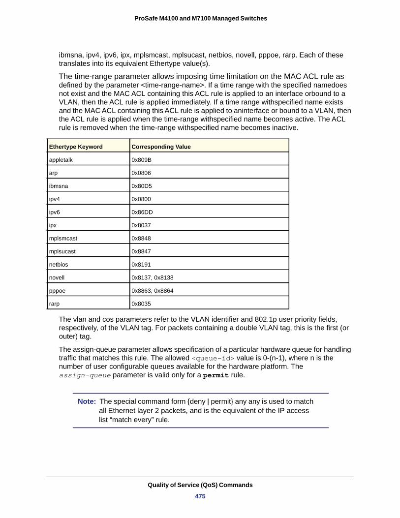
ProSafe M4100 and M7100 Managed Switches
ibmsna, ipv4, ipv6, ipx, mplsmcast, mplsucast, netbios, novell, pppoe, rarp. Each of these translates into its equivalent Ethertype value(s).
The time-range parameter allows imposing time limitation on the MAC ACL rule as defined by the parameter <time-range-name>. If a time range with the specified namedoes not exist and the MAC ACL containing this ACL rule is applied to an interface orbound to a VLAN, then the ACL rule is applied immediately. If a time range withspecified name exists and the MAC ACL containing this ACL rule is applied to aninterface or bound to a VLAN, then the ACL rule is applied when the time-range withspecified name becomes active. The ACL rule is removed when the time-range withspecified name becomes inactive.
The vlan and cos parameters refer to the VLAN identifier and 802.1p user priority fields, respectively, of the VLAN tag. For packets containing a double VLAN tag, this is the first (or outer) tag.
The assign-queue parameter allows specification of a particular hardware queue for handling traffic that matches this rule. The allowed <queue-id> value is 0-(n-1), where n is the number of user configurable queues available for the hardware platform. The assign-queue parameter is valid only for a permit rule.
Note: The special command form {deny | permit} any any is used to match all Ethernet layer 2 packets, and is the equivalent of the IP access list “match every” rule.
Ethertype Keyword Corresponding Value
appletalk 0x809B
arp 0x0806
ibmsna 0x80D5
ipv4 0x0800
ipv6 0x86DD
ipx 0x8037
mplsmcast 0x8848
mplsucast 0x8847
netbios 0x8191
novell 0x8137, 0x8138
pppoe 0x8863, 0x8864
rarp 0x8035
Quality of Service (QoS) Commands
475
ProSafe M4100 and M7100 Managed Switches
mac access-group
This command either attaches a specific MAC access control list (ACL) identified by <name> to an interface, or associates it with a VLAN ID, in a given direction. The <name> parameter must be the name of an existing MAC ACL.
An optional sequence number might be specified to indicate the order of this mac access list relative to other mac access lists already assigned to this interface and direction. A lower number indicates higher precedence order. If a sequence number is already in use for this interface and direction, the specified mac access list replaces the currently attached mac access list using that sequence number. If the sequence number is not specified for this command, a sequence number that is one greater than the highest sequence number currently in use for this interface and direction is used.
This command specified in Interface Config mode only affects a single interface, whereas the Global Config mode setting is applied to all interfaces. The VLAN keyword is only valid in the Global Config mode. The Interface Config mode command is available only on platforms that support independent per-port Class of Service queue configuration.
An optional control-plane is specified to apply the MAC ACL on the CPU port. The control packets, like BPDU, are also dropped because of the implicit deny all rule added to the end of the list. To overcome this, permit rules must be added to allow the control packets.
Note: The <out> option might or might not be available, depending on the platform. The control-plane keyword is available only in Global Config mode.
Format {deny|permit} {<srcmac> | any} {<dstmac> | any} [<ethertypekey> | <0x0600-0xFFFF>] [vlan {eq <0-4095>}] [cos <0-7>] [[log] [time-range <time-range-name>][assign-queue <queue-id>]] [{mirror | redirect} <slot/port>]
Mode Mac-Access-List Config
Format mac access-group <name> {{control-plane|in|out} vlan vlan-id {in|out}} [sequence <1-4294967295>]
Modes • Global Config• Interface Config
Quality of Service (QoS) Commands
476
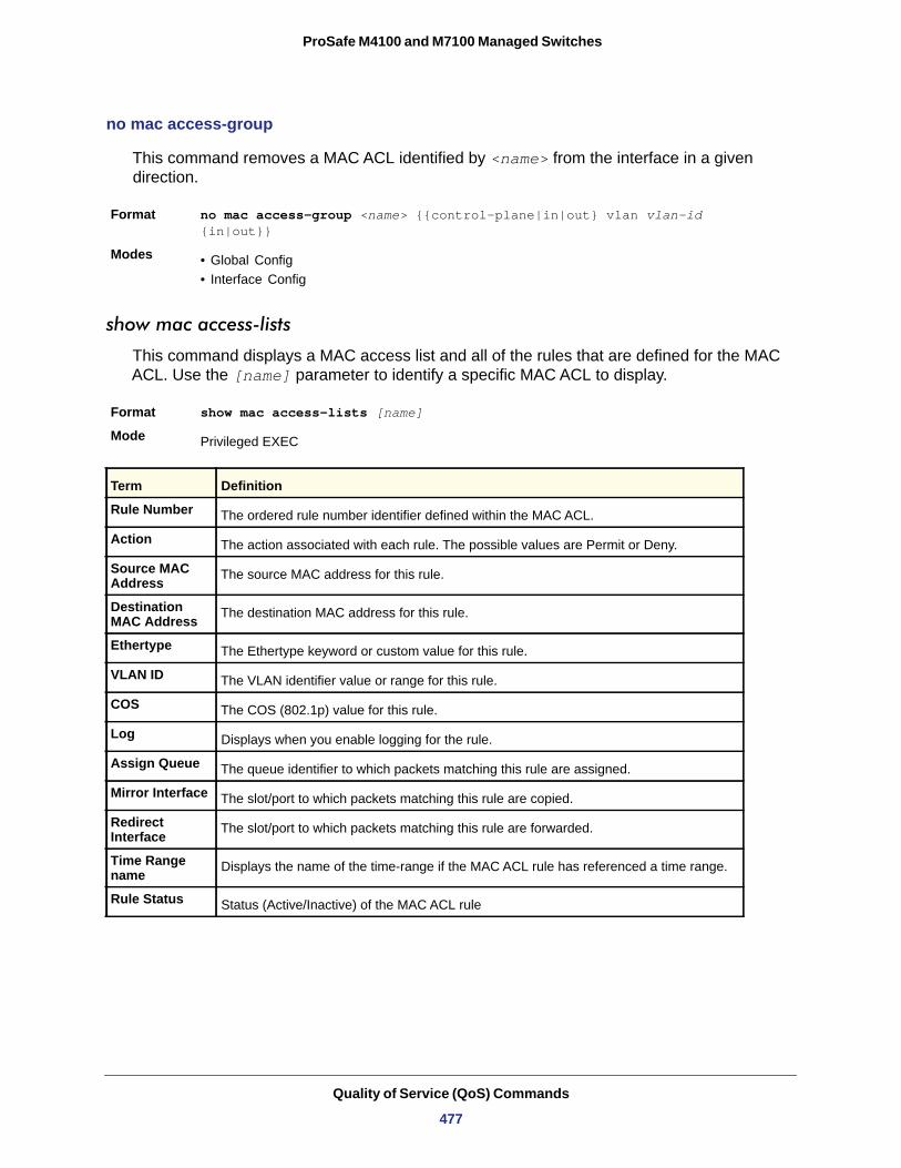
ProSafe M4100 and M7100 Managed Switches
no mac access-group
This command removes a MAC ACL identified by <name> from the interface in a given direction.
Format no mac access-group <name> {{control-plane|in|out} vlan vlan-id {in|out}}
Modes • Global Config• Interface Config
show mac access-lists
This command displays a MAC access list and all of the rules that are defined for the MAC ACL. Use the [name] parameter to identify a specific MAC ACL to display.
Format show mac access-lists [name]
Mode
Rule Number
Action
Source MAC Address
Destination MAC Address
Ethertype
VLAN ID
COS
Log
Assign Queue
Mirror Interface
Redirect Interface
Time Range name
Rule Status
Privileged EXEC
Term Definition
The ordered rule number identifier defined within the MAC ACL.
The action associated with each rule. The possible values are Permit or Deny.
The source MAC address for this rule.
The destination MAC address for this rule.
The Ethertype keyword or custom value for this rule.
The VLAN identifier value or range for this rule.
The COS (802.1p) value for this rule.
Displays when you enable logging for the rule.
The queue identifier to which packets matching this rule are assigned.
The slot/port to which packets matching this rule are copied.
The slot/port to which packets matching this rule are forwarded.
Displays the name of the time-range if the MAC ACL rule has referenced a time range.
Status (Active/Inactive) of the MAC ACL rule
Quality of Service (QoS) Commands
477
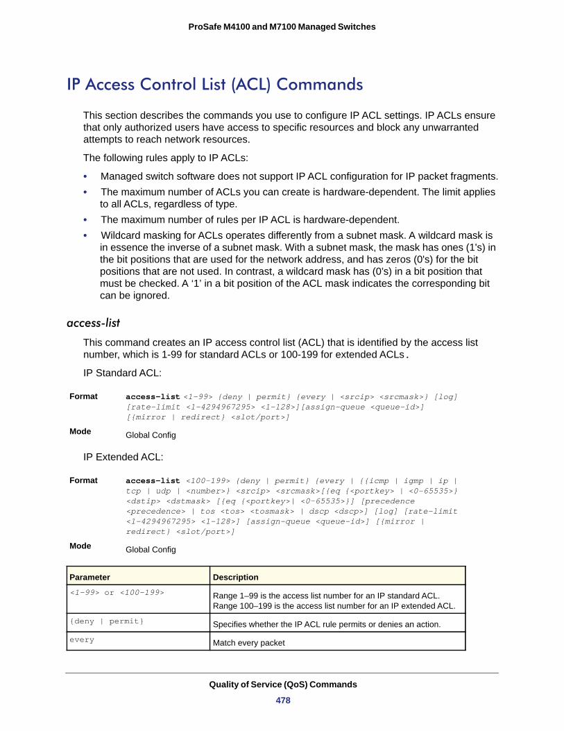
ProSafe M4100 and M7100 Managed Switches
IP Access Control List (ACL) Commands
This section describes the commands you use to configure IP ACL settings. IP ACLs ensure that only authorized users have access to specific resources and block any unwarranted attempts to reach network resources.
The following rules apply to IP ACLs:
• Managed switch software does not support IP ACL configuration for IP packet fragments.• The maximum number of ACLs you can create is hardware-dependent. The limit applies
to all ACLs, regardless of type.• The maximum number of rules per IP ACL is hardware-dependent.• Wildcard masking for ACLs operates differently from a subnet mask. A wildcard mask is
in essence the inverse of a subnet mask. With a subnet mask, the mask has ones (1's) in the bit positions that are used for the network address, and has zeros (0's) for the bit positions that are not used. In contrast, a wildcard mask has (0’s) in a bit position that must be checked. A ‘1’ in a bit position of the ACL mask indicates the corresponding bit can be ignored.
access-list
This command creates an IP access control list (ACL) that is identified by the access list number, which is 1-99 for standard ACLs or 100-199 for extended ACLs.
IP Standard ACL:
Format access-list <1-99> {deny | permit} {every | <srcip> <srcmask>} [log] [rate-limit <1-4294967295> <1-128>][assign-queue <queue-id>] [{mirror | redirect} <slot/port>]
Mode
IP Extended ACL:
Format access-list <100-199> {deny | permit} {every | {{icmp | igmp | ip | tcp | udp | <number>} <srcip> <srcmask>[{eq {<portkey> | <0-65535>} <dstip> <dstmask> [{eq {<portkey>| <0-65535>}] [precedence <precedence> | tos <tos> <tosmask> | dscp <dscp>] [log] [rate-limit <1-4294967295> <1-128>] [assign-queue <queue-id>] [{mirror | redirect} <slot/port>]
Mode
Global Config
Global Config
Parameter Description
<1-99> or <100-199> Range 1–99 is the access list number for an IP standard ACL. Range 100–199 is the access list number for an IP extended ACL.
{deny | permit} Specifies whether the IP ACL rule permits or denies an action.
every Match every packet
Quality of Service (QoS) Commands
478
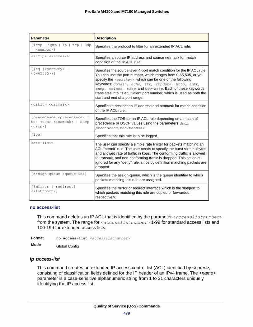
ProSafe M4100 and M7100 Managed Switches
no access-list
This command deletes an IP ACL that is identified by the parameter <accesslistnumber> from the system. The range for <accesslistnumber> 1-99 for standard access lists and 100-199 for extended access lists.
Format no access-list <accesslistnumber>
Mode
ip access-list
This command creates an extended IP access control list (ACL) identified by <name>, consisting of classification fields defined for the IP header of an IPv4 frame. The <name> parameter is a case-sensitive alphanumeric string from 1 to 31 characters uniquely identifying the IP access list.
{icmp | igmp | ip | tcp | udp | <number>}
Specifies the protocol to filter for an extended IP ACL rule.
<srcip> <srcmask> Specifies a source IP address and source netmask for match condition of the IP ACL rule.
[{eq {<portkey> | <0-65535>}]
Specifies the source layer 4-port match condition for the IP ACL rule. You can use the port number, which ranges from 0-65,535, or you specify the <portkey>, which can be one of the following keywords: domain, echo, ftp, ftpdata, http, smtp, snmp, telnet, tftp, and www-http. Each of these keywords translates into its equivalent port number, which is used as both the start and end of a port range.
<dstip> <dstmask> Specifies a destination IP address and netmask for match condition of the IP ACL rule.
[precedence <precedence> | tos <tos> <tosmask> | dscp <dscp>]
Specifies the TOS for an IP ACL rule depending on a match of precedence or DSCP values using the parameters dscp, precedence, tos/tosmask.
[log] Specifies that this rule is to be logged.
rate-limit The user can specify a simple rate limiter for packets matching an ACL “permit” rule. The user needs to specify the burst size in kbytes and allowed rate of traffic in kbps. The conforming traffic is allowed to transmit, and non-conforming traffic is dropped. This action is ignored for any “deny” rule, since by definition matching packets are dropped.
[assign-queue <queue-id>] Specifies the assign-queue, which is the queue identifier to which packets matching this rule are assigned.
[{mirror | redirect} <slot/port>]
Specifies the mirror or redirect interface which is the slot/port to which packets matching this rule are copied or forwarded, respectively.
Global Config
Parameter Description
Quality of Service (QoS) Commands
479
ProSafe M4100 and M7100 Managed Switches
If an IP ACL by this name exists, this command enters IPv4-Access_List config mode to allow updating the existing IP ACL.
Note: The CLI mode changes to IPv4-Access-List Config mode when you successfully execute this command.
no ip access-list
This command deletes the IP ACL identified by <name> from the system.
Format no ip access-list <name>
Mode
ip access-list rename
This command changes the name of an IP access control list (ACL). The <name> parameter is the names of an existing IP ACL. The <newname> parameter is a case-sensitive alphanumeric string from 1 to 31 characters uniquely identifying the IP access list.
This command fails is an IP ACL by the name <newname> exists.
Format ip access-list rename <name> <newname>
Mode
{deny | permit} (IP ACL)
This command creates a new rule for the current IP access list. Each rule is appended to the list of configured rules for the list.
Note: The “no” form of this command is not supported, since the rules within an IP ACL cannot be deleted individually. Rather, the entire IP ACL must be deleted and respecified.
Note: An implicit “deny all” IP rule always terminates the access list.
Format ip access-list <name>
Mode Global Config
Global Config
Global Config
Quality of Service (QoS) Commands
480
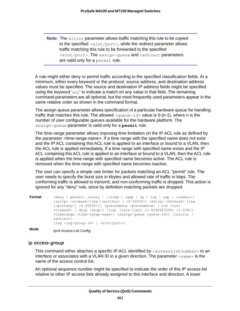
ProSafe M4100 and M7100 Managed Switches
Note: The mirror parameter allows traffic matching this rule to be copied to the specified <slot/port>, while the redirect parameter allows traffic matching this rule to be forwarded to the specified <slot/port>. The assign-queue and redirect parameters are valid only for a permit rule.
A rule might either deny or permit traffic according to the specified classification fields. At a minimum, either every keyword or the protocol, source address, and destination address values must be specified. The source and destination IP address fields might be specified using the keyword ‘any’ to indicate a match on any value in that field. The remaining command parameters are all optional, but the most frequently used parameters appear in the same relative order as shown in the command format.
The assign-queue parameter allows specification of a particular hardware queue for handling traffic that matches this rule. The allowed <queue-id> value is 0-(n-1), where n is the number of user configurable queues available for the hardware platform. The assign-queue parameter is valid only for a permit rule.
The time-range parameter allows imposing time limitation on the IP ACL rule as defined by the parameter <time-range-name>. If a time range with the specified name does not exist and the IP ACL containing this ACL rule is applied to an interface or bound to a VLAN, then the ACL rule is applied immediately. If a time range with specified name exists and the IP ACL containing this ACL rule is applied to an interface or bound to a VLAN, then the ACL rule is applied when the time-range with specified name becomes active. The ACL rule is removed when the time-range with specified name becomes inactive.
The user can specify a simple rate limiter for packets matching an ACL “permit” rule. The user needs to specify the burst size in kbytes and allowed rate of traffic in kbps. The conforming traffic is allowed to transmit, and non-conforming traffic is dropped. This action is ignored for any “deny” rule, since by definition matching packets are dropped.
Format {deny | permit} {every | {{icmp | igmp | ip | tcp | udp | <number>} <srcip> <srcmask>[{eq {<portkey> | <0-65535>} <dstip> <dstmask> [{eq {<portkey>| <0-65535>}] [precedence <precedence> | tos <tos> <tosmask> | dscp <dscp>] [log] [rate-limit <1-4294967295> <1-128>] [timerange <time-range-name>] [assign-queue <queue-id>] [{mirror | redirect}[lag <lag-group-id> | <slot/port>]
Mode
ip access-group
This command either attaches a specific IP ACL identified by <accesslistnumber> to an interface or associates with a VLAN ID in a given direction. The parameter <name> is the name of the access control list.
An optional sequence number might be specified to indicate the order of this IP access list relative to other IP access lists already assigned to this interface and direction. A lower
Ipv4-Access-List Config
Quality of Service (QoS) Commands
481
ProSafe M4100 and M7100 Managed Switches
number indicates higher precedence order. If a sequence number is already in use for this interface and direction, the specified access list replaces the currently attached IP access list using that sequence number. If the sequence number is not specified for this command, a sequence number that is one greater than the highest sequence number currently in use for this interface and direction is used.
Note: The <out> option might not be available, depending on the platform.
no ip access-group
This command removes a specified IP ACL from an interface.
Default
Format no ip access-group <accesslistnumber> {{control-plane|in|out}|vlan <vlan-id> {in|out}}
Mode • Interface Config• Global Config
acl-trapflags
This command enables the ACL trap mode.
Default
Format acl-trapflags
Mode
no acl-trapflags
This command disables the ACL trap mode.
Format no acl-trapflags
Mode
Default none
Format ip access-group {<accesslistnumber>|<name>} {{control-plane|in|out}|vlan <vlan-id> {in|out}}[sequence <1-4294967295>]
Modes • Interface Config• Global Config
none
disabled
Global Config
Global Config
Quality of Service (QoS) Commands
482
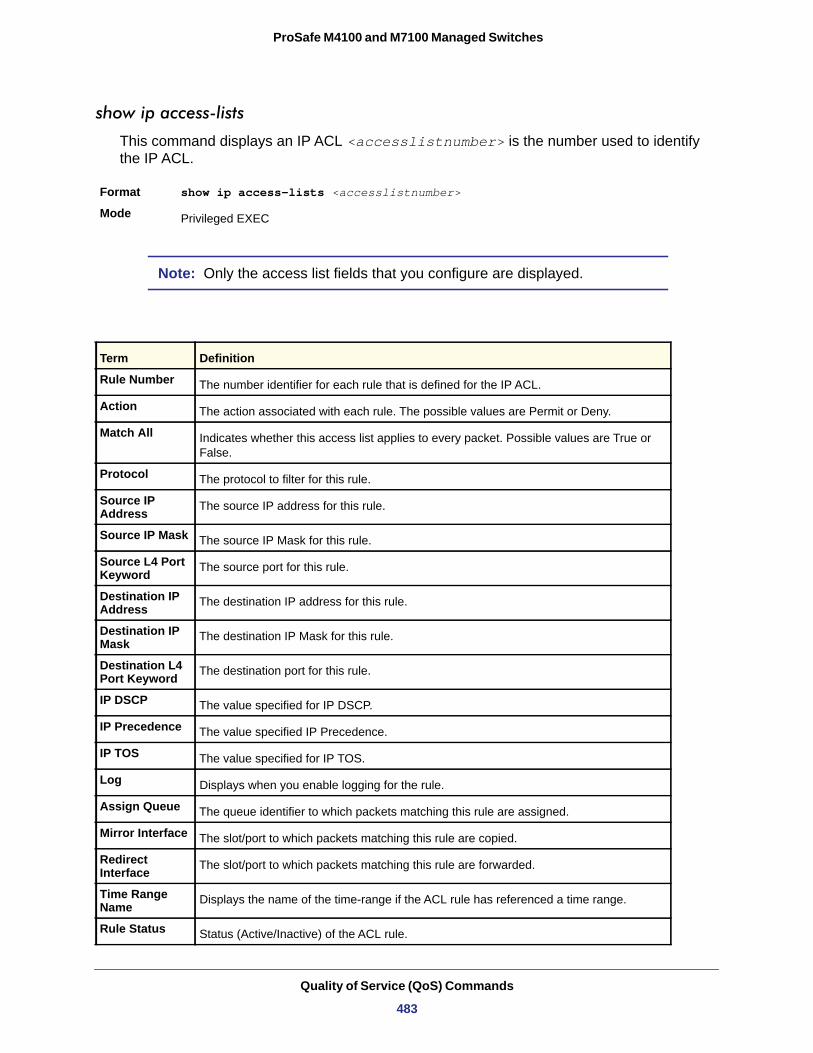
ProSafe M4100 and M7100 Managed Switches
show ip access-lists
This command displays an IP ACL <accesslistnumber> is the number used to identify the IP ACL.
Format show ip access-lists <accesslistnumber>
Mode
Note: Only the access list fields that you configure are displayed.
Privileged EXEC
Term Definition
Rule Number The number identifier for each rule that is defined for the IP ACL.
Action The action associated with each rule. The possible values are Permit or Deny.
Match All Indicates whether this access list applies to every packet. Possible values are True or False.
Protocol The protocol to filter for this rule.
Source IP Address The source IP address for this rule.
Source IP Mask The source IP Mask for this rule.
Source L4 Port Keyword The source port for this rule.
Destination IP Address The destination IP address for this rule.
Destination IP Mask The destination IP Mask for this rule.
Destination L4 Port Keyword The destination port for this rule.
IP DSCP The value specified for IP DSCP.
IP Precedence The value specified IP Precedence.
IP TOS The value specified for IP TOS.
Log Displays when you enable logging for the rule.
Assign Queue The queue identifier to which packets matching this rule are assigned.
Mirror Interface The slot/port to which packets matching this rule are copied.
Redirect Interface The slot/port to which packets matching this rule are forwarded.
Time Range Name Displays the name of the time-range if the ACL rule has referenced a time range.
Rule Status Status (Active/Inactive) of the ACL rule.
Quality of Service (QoS) Commands
483
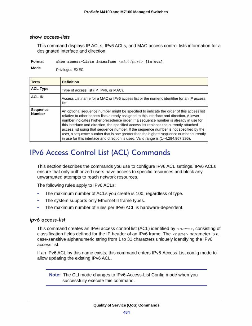
ProSafe M4100 and M7100 Managed Switches
show access-lists
This command displays IP ACLs, IPv6 ACLs, and MAC access control lists information for a designated interface and direction.
Format show access-lists interface <slot/port> [in|out]
Mode
ACL Type
ACL ID
Sequence Number
IPv6 Access Control List (ACL) Commands
This section describes the commands you use to configure IPv6 ACL settings. IPv6 ACLs ensure that only authorized users have access to specific resources and block any unwarranted attempts to reach network resources.
The following rules apply to IPv6 ACLs:
• The maximum number of ACLs you create is 100, regardless of type.• The system supports only Ethernet II frame types.• The maximum number of rules per IPv6 ACL is hardware-dependent.
ipv6 access-list
This command creates an IPv6 access control list (ACL) identified by <name>, consisting of classification fields defined for the IP header of an IPv6 frame. The <name> parameter is a case-sensitive alphanumeric string from 1 to 31 characters uniquely identifying the IPv6 access list.
If an IPv6 ACL by this name exists, this command enters IPv6-Access-List config mode to allow updating the existing IPv6 ACL.
Note: The CLI mode changes to IPv6-Access-List Config mode when you successfully execute this command.
Privileged EXEC
Term Definition
Type of access list (IP, IPv6, or MAC).
Access List name for a MAC or IPv6 access list or the numeric identifier for an IP access list.
An optional sequence number might be specified to indicate the order of this access list relative to other access lists already assigned to this interface and direction. A lower number indicates higher precedence order. If a sequence number is already in use for this interface and direction, the specified access list replaces the currently attached access list using that sequence number. If the sequence number is not specified by the user, a sequence number that is one greater than the highest sequence number currently in use for this interface and direction is used. Valid range is (1–4,294,967,295).
Quality of Service (QoS) Commands
484
ProSafe M4100 and M7100 Managed Switches
no ipv6 access-list
This command deletes the IPv6 ACL identified by <name> from the system.
Format no ipv6 access-list <name>
Mode
ipv6 access-list rename
This command changes the name of an IPv6 ACL. The <name> parameter is the name of an existing IPv6 ACL. The <newname> parameter is a case-sensitive alphanumeric string from 1 to 31 characters uniquely identifying the IPv6 access list.
This command fails is an IPv6 ACL by the name <newname> already exists.
Format ipv6 access-list rename <name> <newname>
Mode
{deny | permit} (IPv6)
This command creates a new rule for the current IPv6 access list. Each rule is appended to the list of configured rules for the list.
Note: The ‘no’ form of this command is not supported, since the rules within an IPv6 ACL cannot be deleted individually. Rather, the entire IPv6 ACL must be deleted and respecified.
Note: An implicit ‘deny all’ IPv6 rule always terminates the access list.
A rule might either deny or permit traffic according to the specified classification fields. At a minimum, either the ‘every’ keyword or the protocol, source address, and destination address values must be specified. The source and destination IPv6 address fields might be specified using the keyword ‘any’ to indicate a match on any value in that field. The remaining command parameters are all optional, but the most frequently used parameters appear in the same relative order as shown in the command format.
The assign-queue parameter allows specification of a particular hardware queue for handling traffic that matches this rule. The allowed <queue-id> value is 0-(n-1), where n is the
Format ipv6 access-list <name>
Mode Global Config
Global Config
Global Config
Quality of Service (QoS) Commands
485
ProSafe M4100 and M7100 Managed Switches
number of user configurable queues available for the hardware platform. The assign-queue parameter is valid only for a permit rule.
The mirror parameter allows the traffic matching this rule to be copied to the specified <slot/port>, while the redirect parameter allows the traffic matching this rule to be forwarded to the specified <slot/port>. The assign-queue and redirect parameters are only valid for a permit rule.
The time-range parameter allows imposing time limitation on the IPv6 ACL rule as defined by the parameter <time-range-name>. If a time range with the specified name does not exist and the IPv6 ACL containing this ACL rule is applied to an interface or bound to a VLAN, then the ACL rule is applied immediately. If a time range with specified name exists and the IPv6 ACL containing this ACL rule is applied to an interface or bound to a VLAN, then the ACL rule is applied when the time-range with specified name becomes active. The ACL rule is removed when the time-range with specified name becomes inactive.
Format {deny | permit} {every | {{icmp | igmp | ipv6 | tcp | udp | <number>}[log] [timerange<time-range-name>] [assign-queue <queue-id>] [{mirror | redirect} <slot/port>]
Mode
ipv6 traffic-filter
This command either attaches a specific IPv6 ACL identified by <name> to an interface or associates with a VLAN ID in a given direction. The <name> parameter must be the name of an existing IPv6 ACL.
An optional sequence number might be specified to indicate the order of this mac access list relative to other IPv6 access lists already assigned to this interface and direction. A lower number indicates higher precedence order. If a sequence number is already in use for this interface and direction, the specifiedIPv6 access list replaces the currently attached IPv6 access list using that sequence number. If the sequence number is not specified for this command, a sequence number that is one greater than the highest sequence number currently in use for this interface and direction is used.
This command specified in Interface Config mode only affects a single interface, whereas the Global Config mode setting is applied to all interfaces. The vlan keyword is only valid in the Global Config mode. The Interface Config mode command is only available on platforms that support independent per-port Class of Service queue configuration.
Note: You should be aware that the <out> option may or may not be available, depending on the platform.
IPv6-Access-List Config
Quality of Service (QoS) Commands
486
ProSafe M4100 and M7100 Managed Switches
no ipv6 traffic-filter
This command removes an IPv6 ACL identified by <name> from the interface(s) in a given direction.
Format no ipv6 traffic-filter <name> {{control-plane|in|out}|vlan <vlan-id> {in|out}}
Modes • Global Config• Interface Config
show ipv6 access-lists
This command displays an IPv6 access list and all of the rules that are defined for the IPv6 ACL. Use the [name] parameter to identify a specific IPv6 ACL to display.
Format show ipv6 access-lists [name]
Mode
Format ipv6 traffic-filter <name> {{control-plane|in|out}|vlan <vlan-id> {in|out}} [sequence <1-4294967295>]
Modes • Global Config• Interface Config
Privileged EXEC
Term Definition
Rule Number The ordered rule number identifier defined within the IPv6 ACL.
Action The action associated with each rule. The possible values are Permit or Deny.
Match All Indicates whether this access list applies to every packet. Possible values are True or False.
Protocol The protocol to filter for this rule.
Source IP Address The source IP address for this rule.
Source L4 Port Keyword The source port for this rule.
Destination IP Address The destination IP address for this rule.
Destination L4 Port Keyword The destination port for this rule.
IP DSCP The value specified for IP DSCP.
Flow Label The value specified for IPv6 Flow Label.
Log Displays when you enable logging for the rule.
Assign Queue The queue identifier to which packets matching this rule are assigned.
Quality of Service (QoS) Commands
487
ProSafe M4100 and M7100 Managed Switches
Time Range Commands for Time-Based ACLs
Time-based ACLs allow one or more rules within an ACL to be based on time. Each ACL rule within an ACL, except for the implicit deny all rule, can be configured to be active and operational only during a specific time period. The time range commands allow you to define specific times of the day and week to implement time-based ACLs. The time range is identified by a name and can then be referenced by an ACL rule defined with in an ACL.
time-range
Use this command to create a time range identified by name, consisting of one absolute time entry and/or one or more periodic time entries. The name parameter is a case-sensitive, alphanumeric string from 1 to 31 characters that uniquely identifies the time range. An alpha-numeric string is defined as consisting of only alphabetic, numeric, dash, underscore, or space characters. If a time range by this name exists, this command enters Time-Range config mode to allow updating the time range entries
Note: When you successfully execute this command, the CLI mode changes to Time-Range Config mode.
Format time-range <name>
Mode
no time-range
Use this command to delete a time-range identified by name.
Format no time-range <name>
Mode
absolute
Use this command to add an absolute time entry to a time range. Only one absolute time entry is allowed per time-range. The time parameter is based on the currently configured
Mirror Interface The slot/port to which packets matching this rule are copied.
Redirect Interface The slot/port to which packets matching this rule are forwarded.
Time Range Name Displays the name of the time-range if the IPv6 ACL rule has referenced a time range.
Rule Status Status(Active/Inactive) of the IPv6 ACL rule.
Global Config
Global Config
Term Definition
Quality of Service (QoS) Commands
488
ProSafe M4100 and M7100 Managed Switches
time zone. The [start time date] parameters indicate the time and date at which the configuration that referenced the time range starts going into effect. The time is expressed in a 24-hour clock, in the form of hours:minutes. For example, 8:00 is 8:00 am and 20:00 is 8:00 pm. The date is expressed in the format day month year. If no start time and date are specified, the configuration statement is in effect immediately. The [end time date] parameters indicate the time and date at which the configuration that referenced the time range is no longer in effect. The end time and date must be after the start time and date. If no end time and date are specified, the configuration statement is in effect indefinitely.
Format absolute {[start time date] [end time date]}
Mode
no absolute
Use this command to delete the absolute time entry in the time range.
Format no absolute
Mode
periodic
Use this command to add a periodic time entry to a time range. The time parameter is based off the currently configured time zone. The first occurrence of the days-of-the-week argument is the starting day(s) from which the configuration that referenced the time range starts going into effect. The second occurrence is the ending day or days from which the configuration that referenced the time range is no longer in effect. If the end days-of-the-week are the same as the start, they can be omitted This argument can be any single day or combinations of days: Monday, Tuesday, Wednesday, Thursday, Friday, Saturday, Sunday. Other possible values are:
• daily—Monday through Sunday • weekdays—Monday through Friday • weekend—Saturday and Sunday
If the ending days of the week are the same as the starting days of the week, they can be omitted. The first occurrence of the time argument is the starting hours:minutes which the configuration that referenced the time range starts going into effect. The second occurrence is the ending hours:minutes at which the configuration that referenced the time range is no longer in effect. The hours:minutes are expressed in a 24-hour clock. For example, 8:00 is 8:00 am and 20:00 is 8:00 pm
The frequency is how often this periodic entry will become active. If the value is set to 0, the timer schedule will be treated as absolute.
Format periodic <frequency> {days-of-the-week time} to {[days-of-the-week] time}
Mode
Time-Range Config
Time-Range Config
Time-Range Config
Quality of Service (QoS) Commands
489
ProSafe M4100 and M7100 Managed Switches
no periodic
Use this command to delete a periodic time entry from a time range.
Format no periodic <frequency>{days-of-the-week time} to {[days-of-the-week] time}
Mode
periodic {start|end} time
Use this command to configure the start/end time for the time-range.
Format periodic {start|end} time
Mode
show time-range
Use this command to display a time range and all the absolute/periodic time entries that are defined for the time range. Use the name parameter to identify a specific time range to display. When name is not specified, all the time ranges defined in the system are displayed.
Format show time-range
Mode
Number of Time Ranges
Time Range Name
Time Range Status
Absolute start
Absolute end
Periodic Entries
Periodic start
Periodic end
AutoVOIP
AutoVoIP detects the VoIP streams and put the VoIP streams in the specific VLAN (auto-voip VLAN) and provides higher Class of Service to the VoIP streams automatically (both data and signaling). It detects the VoIP streams in two modes.
Protocol-based Auto VoIP
Time-Range Config
Time-Range Config
Privileged EXEC
Term Definition
Number of time ranges configured in the system.
Name of the time range.
Status of the time range (active/inactive).
Start time and day for absolute time entry.
End time and day for absolute time entry.
Number of periodic entries in a time-range.
Start time and day for periodic entry.
End time and day for periodic entry.
Quality of Service (QoS) Commands
490
ProSafe M4100 and M7100 Managed Switches
In a VoIP system, various signaling protocols are used to establish the connection between two VoIP devices. The supported signaling protocols are SIP, H.323, and SCCP.
OUI-based Auto VoIP
The OUI-based Auto VoIP feature prioritizes VoIP packets based on the OUI bytes in the source MAC address. A default list of OUIs is maintained. User is also allowed to configure OUIs that need prioritization apart from the default OUI list. Up to 128 OUIs are allowed on the device or system, including the default OUIs.
Note: If voice VLAN and Auto-VoIP are enabled at the same time, one of them is operational. If the connected phone is LLDP-MED capable, voice VLAN has precedence over the Auto VoIP and Auto VoIP is operational if the phone does not support LLDP-MED.
auto-voip {protocol-based | oui-based}
This command is used to configure auto VoIP mode. The supported modes are protocol-based and oui-based. Protocol-based auto VoIP prioritizes the voice data based on the layer 4 port used for the voice session. OUI-based auto VOIP prioritizes the phone traffic based on the known OUI of the phone.
Format auto-voip {protocol-based | oui-based}
Mode • Global Config• Interface Config
Default
no auto-voip {protocol-based | oui-based}
This command is used to set default mode.
Format no auto-voip {protocol-based | oui-based}
Mode • Global Config• Interface Config
auto-voip oui
This command is used to configure an OUI for Auto VoIP. The traffic from the configured OUI will get the highest priority over the other traffic.
Format auto-voip oui <oui-prefix> oui-desc <string>
Mode
Default
oui-based
Global Config
A list of known OUIs is present
Quality of Service (QoS) Commands
491
ProSafe M4100 and M7100 Managed Switches
no auto-voip oui
This command is to delete already configured OUI.
Format no auto-voip oui <oui-prefix>
Mode
auto-voip vlan
This command is used to configure the global Auto VoIP VLAN id. The VLAN behavior is depend on the configured auto VoIP mode.
Format auto-voip vlan <vlanid>
Mode
Default
no auto-voip vlan
This command is used to set the auto-voip VLAN to the default 2.
Format no auto-voip vlan
Mode
auto-voip oui-based priority
This command is used to configure the global OUI based auto VoIP priority. If the phone OUI is matches one of the configured OUI, the priority of traffic from the phone is changed to OUI priority configured through this command.
Format auto-voip oui-based priority <priority-value>
Mode
Default
no auto-voip oui-based priority
This command is used to set the priority to the default value.
Format no auto-voip oui-based priority <priority-value>
Mode
auto-voip protocol-based {remark | traffic-class}
This command is used to configure the global protocol based auto-VoIP remarking priority/traffic-class. If the remark priority is configured, the voice data of the session is remarked with the priority configured through this command.
Global Config
Global Config
None
Global Config
Global Config
Highest available priority
Global Config
Quality of Service (QoS) Commands
492
ProSafe M4100 and M7100 Managed Switches
Note: The administrator has to enable tagging on auto-VoIP-enabled ports to remark the voice data when it is egressed.
Format auto-voip protocol-based {remark <remark-priority> | traffic-class <tc>}
Mode • Global Config• Interface Config
Default
no auto-voip protocol-based {remark | traffic-class}
This command is used to set the traffic-class to the default value.
Format no auto-voip protocol-based {remark <remark- priority> | traffic-class <tc>}
Mode • Global Config• Interface Config
show auto-voip
Use this command to display the auto VoIP settings on the interface or interfaces of the switch.
Format show auto-voip {protocol-based|oui-based} interface {slot/port|all}
Mode
VoIP
Prioritize Type
Class Value • If the Prioritization Type is configured as traffic-class, this value is the queue value.
• If the Prioritization Type is configured as remark, this value is 802.1p priority used to remark the voice traffic.
Priority
AutoVoIPMode
Example 1: The following shows an example of a CLI display output for the command.
(switch)# show auto-voip protocol-based interface all
VoIP VLAN Id................................... 2Prioritization Type............................ traffic-classClass Value.................................... 7
Traffic-class 7
Privileged EXEC
Field Description
The global VoIP VLAN ID.
The type of prioritization used on voice traffic.
The 802.1p priority. This field is valid for OUI auto VoIP.
The Auto VoIP mode on the interface.
Quality of Service (QoS) Commands
493
ProSafe M4100 and M7100 Managed Switches
Interface Auto VoIP Operational StatusMode
--------- -------------- ------------------0/1 Disabled Down0/2 Disabled Down0/3 Disabled Down0/4 Disabled Down
Example: The following shows an example of a CLI display output for the command.
(Netgear Switch)# show auto-voip oui-based interface all
VoIP VLAN Id................................... 2Priority....................................... 7
Interface Auto VoIP Operational StatusMode
--------- -------------- ------------------0/1 Disabled Down0/2 Disabled Down0/3 Disabled Down0/4 Disabled Down0/5 Disabled Down
show auto-voip oui-table
This command lists all of the configured OUIs.
Format show auto-voip oui-table
Mode • Privileged EXEC• User EXEC
OUI
Status
OUI Description
Example: show auto-voip oui-table
OUI Status Description--------- ---------- ---------00:01:E3 Default SIEMENS00:03:6B Default CISCO100:01:01 Configured VoIP phone
iSCSI Commands
The tasks involved in providing automated QoS preferential treatment of iSCSI flows can be divided into the following categories:
Term Definition
OUI of the source MAC address
Default or Configured entry.
Description of the OUI
Quality of Service (QoS) Commands
494
ProSafe M4100 and M7100 Managed Switches
• Detecting the establishment and termination of iSCSI sessions and connections by snooping packets used in the iSCSI protocol.
• Maintaining a database of currently active iSCSI sessions and connections to store data about the participants. This allows the formulation of classifier rules giving the data packets for the session the desired QoS treatment.
• Installing and removing classifier rule sets as needed for the iSCSI session traffic.• Monitoring activity in the iSCSI sessions to allow for aging out session entries if the
session termination packets are not received.
The means of detecting the establishment and termination of iSCSI sessions is accomplished by installing classifier rules to trap iSCSI protocol packets to the CPU for examination. This protocol uses well-known TCP ports for initiators to contact targets with 3260 and 860. Additional port numbers or “port number/target IP address” can also be configured for monitoring if an installation uses ports other than the well-known ports. The well-known ports are configured as part of the default configuration of the component and can be removed if desired by the user.
iscsi enable
The iscsi enable Global Configuration mode command globally enables iSCSI awareness.
Format iscsi enable
Mode
Default
no iscsi enable
This command is to disable iSCSI awareness use the no form of this command. When User uses this command, iSCSI resources will be released.
Format no iscsi enable
Mode
Default
iscsi target port
This command configures iSCSI port/s, target addresses, and names.
Note: When working with private iSCSI ports (not IANA assigned iSCSI ports 3260/860), it is recommended to specify the target IP address as well, so the switch will only snoop frames with which the TCP destination port is one of the configured TCP ports, and the destination IP is the target’s IP address. This way the CPU is not to be falsely loaded by non-iSCSI flows (if by chance other applications
Global Config
Disabled
Global Config
Disabled
Quality of Service (QoS) Commands
495
ProSafe M4100 and M7100 Managed Switches
also choose to use these {unreserved} ports). When a port is already defined and not bound to an IP, and the User wants to bind it to an IP, the User should first remove it by using the no form of the command and then add it again, this time together with the relevant IP. Target names are only for display when using show iscsi command. These names are not use to match (or for doing any sanity check) with the iSCSI session information acquired by snooping. Maximum of 16 TCP ports can be configured either bound to IP or not.
Format iscsi target port tcp-port-1 [tcp-port-2.… tcp-port-8] [address ip-address] [name targetname]
Mode
Default
tcp-port
ip-address
targetname
no iscsi target port
This command is to delete iSCSI port/s, target, use the no form of this command.
Format no iscsi target port tcp-port-1 [tcp-port-2.… tcp-port-8] [address ip-address]
Mode
iscsi cos
The iscsi cos Global Configuration mode command sets the Quality of Service profile that will be applied to iSCSI flows.
Global Config
3260 and 860, but they can be removed as any other configured target
Term Definition
TCP port number or list of TCP port numbers on which iSCSI target/s listen to requests. Up to 16 TCP ports can be defined in the system in one command or by using multiple commands.
IP address of the iSCSI target. When the no form is used, and the tcp port to be deleted is one bound to a specific IP address, the address field must be present.
iSCSI name of the iSCSI target. The name can be statically configured; however, it can be obtained from iSNS or from sendTargets response. The initiator must present both its iSCSI Initiator Name and the iSCSI Target Name to which it wishes to connect in the first login request of a new session or connection.
Global Config
Quality of Service (QoS) Commands
496
ProSafe M4100 and M7100 Managed Switches
Note: SCSI flows are assigned by default to the highest VPT/DSCP mapped to the highest queue not used for stack management or voice VLAN. The user should also take care of configuring the relevant Class of Service parameters for the queue in order to complete the setting. Setting the VPT/DSCP sets the QoS profile which determines the egress queue to which the frame is mapped. The switch default setting for egress queues scheduling is Weighted Round Robin (WRR). The user might complete the QoS setting by configuring the relevant ports to work in other scheduling and queue management modes via the Class of Service settings. Depending on the platform, these choices might include strict priority for the queue used for iSCSI traffic. The downside of strict priority is that, in certain circumstances (under heavy high priority traffic), other lower priority traffic might get starved. In WRR the queue to which the flow is assigned to can be set to get the required percentage.
Format iscsi cos traffic-class {vpt <vpt> | dscp <dscp>} [remark]
Mode
traffic-class
vpt/dscp
remark
no iscsi cos
This command is to set the Quality of Service profile of SCSI flows to default.
Format no iscsi cos
Mode
iscsi aging time
The iscsi aging time Global Configuration mode command sets aging time for iSCSI sessions.
Behavior when changing aging time:
Global Config
Term Definition
The traffic class used for assigning iSCSI traffic to a queue.
The VLAN Priority Tag or DSCP to assign iSCSI session packets.
Mark the iSCSI frames with the configured VPT/DSCP when egressing the switch.
Global Config
Quality of Service (QoS) Commands
497
ProSafe M4100 and M7100 Managed Switches
• When aging time is increased - Current sessions will be timed out according to the new value.
• When aging time is decreased - Any sessions that have been dormant for a time exceeding the new setting will be immediately deleted from the table. All other sessions will continue to be monitored against the new time-out value.
Format iscsi aging time <time>
Mode
Default
time
no iscsi aging time
This command is to reset the aging time to the default.
Format no iscsi aging time
Mode
show iscsi
This command displays the iSCSI settings.
Format show iscsi
Mode • Privileged EXEC• User EXEC
Example:
The following example displays the iSCSI settings.
Console # show iscsiiSCSI enablediSCSI vpt is 5, remarkSession aging time: 60 minMaximum number of sessions is 256-----------------------------------------------------------iSCSI targets and TCP ports:---------------------------TCP Port Target IP Address Name860 3260 5000 30001 172.16.1.1 iqn.1993-11.com.disk-vendor:diskarrays.sn.45678.tape:sys1.xyz 30033 172.16.1.10 30033 172.16.1.25
Global Config
5 minutes
Term Definition
The number in minutes a session is not active prior to its removal. (Range: 1-43,200)
Global Config
Quality of Service (QoS) Commands
498
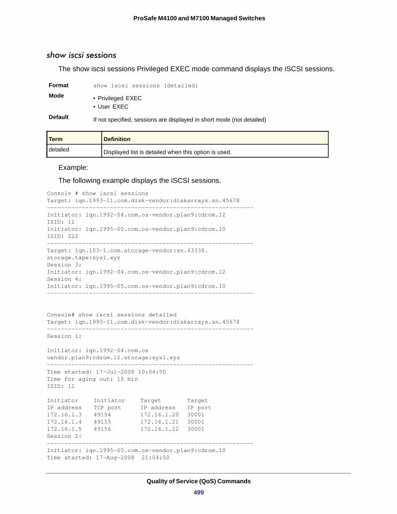
ProSafe M4100 and M7100 Managed Switches
show iscsi sessions
The show iscsi sessions Privileged EXEC mode command displays the iSCSI sessions.
Format show iscsi sessions [detailed]
Mode • Privileged EXEC• User EXEC
Default
detailed
Example:
The following example displays the iSCSI sessions.
Console # show iscsi sessionsTarget: iqn.1993-11.com.disk-vendor:diskarrays.sn.45678-----------------------------------------------------------Initiator: iqn.1992-04.com.os-vendor.plan9:cdrom.12ISID: 11Initiator: iqn.1995-05.com.os-vendor.plan9:cdrom.10ISID: 222-----------------------------------------------------------Target: iqn.103-1.com.storage-vendor:sn.43338. storage.tape:sys1.xyzSession 3:Initiator: iqn.1992-04.com.os-vendor.plan9:cdrom.12Session 4:Initiator: iqn.1995-05.com.os-vendor.plan9:cdrom.10-----------------------------------------------------------
Console# show iscsi sessions detailedTarget: iqn.1993-11.com.disk-vendor:diskarrays.sn.45678-----------------------------------------------------------Session 1:
Initiator: iqn.1992-04.com.osvendor.plan9:cdrom.12.storage:sys1.xyz-----------------------------------------------------------Time started: 17-Jul-2008 10:04:50Time for aging out: 10 minISID: 11
Initiator Initiator Target TargetIP address TCP port IP address IP port172.16.1.3 49154 172.16.1.20 30001 172.16.1.4 49155 172.16.1.21 30001 172.16.1.5 49156 172.16.1.22 30001 Session 2: -----------------------------------------------------------Initiator: iqn.1995-05.com.os-vendor.plan9:cdrom.10Time started: 17-Aug-2008 21:04:50
If not specified, sessions are displayed in short mode (not detailed)
Term Definition
Displayed list is detailed when this option is used.
Quality of Service (QoS) Commands
499
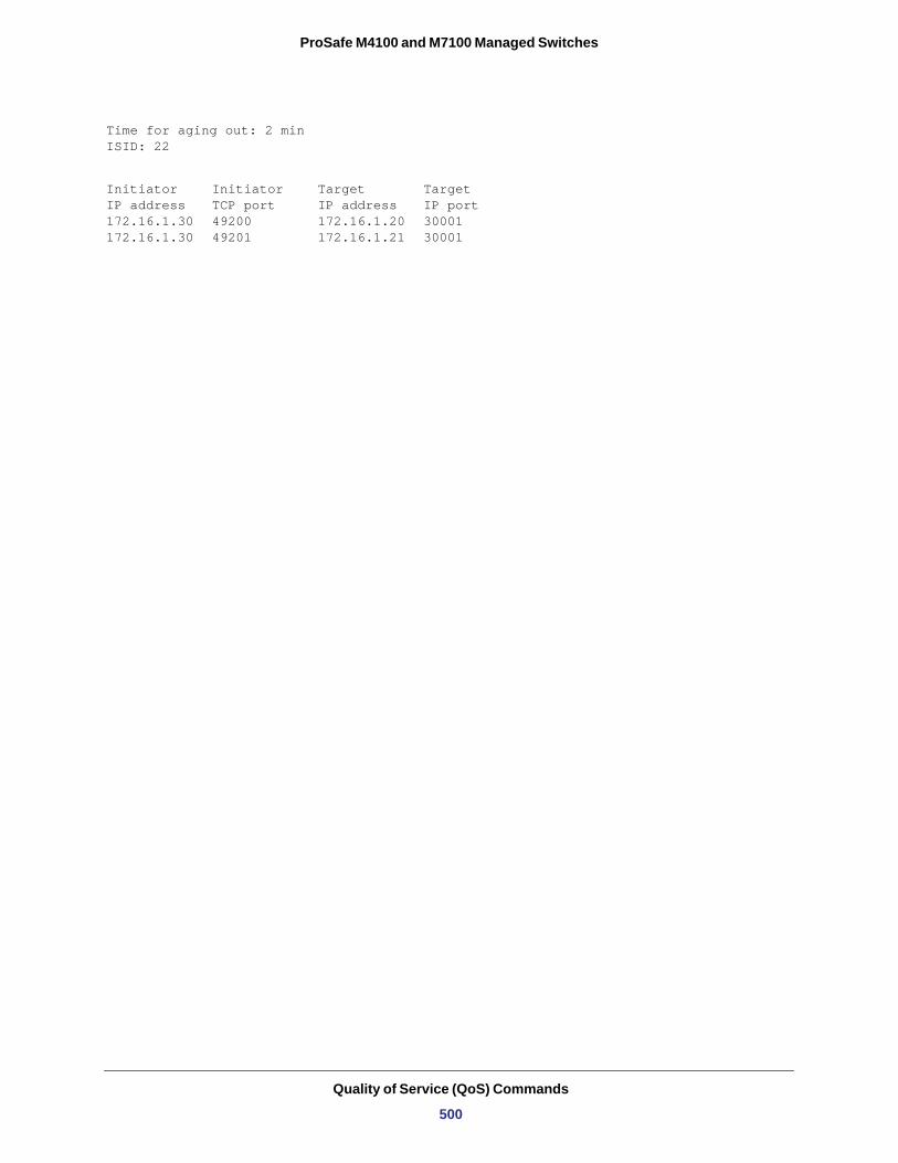
ProSafe M4100 and M7100 Managed Switches
Time for aging out: 2 minISID: 22
Initiator Initiator Target Target IP address TCP port IP address IP port 172.16.1.30 49200 172.16.1.20 30001 172.16.1.30 49201 172.16.1.21 30001
Quality of Service (QoS) Commands
500
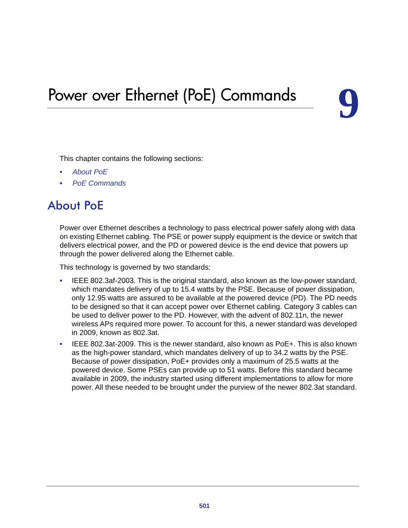
9
9. Power over Ethernet (PoE) CommandsThis chapter contains the following sections:
• About PoE • PoE Commands
About PoE
Power over Ethernet describes a technology to pass electrical power safely along with data on existing Ethernet cabling. The PSE or power supply equipment is the device or switch that delivers electrical power, and the PD or powered device is the end device that powers up through the power delivered along the Ethernet cable.
This technology is governed by two standards:
• IEEE 802.3af-2003. This is the original standard, also known as the low-power standard, which mandates delivery of up to 15.4 watts by the PSE. Because of power dissipation, only 12.95 watts are assured to be available at the powered device (PD). The PD needs to be designed so that it can accept power over Ethernet cabling. Category 3 cables can be used to deliver power to the PD. However, with the advent of 802.11n, the newer wireless APs required more power. To account for this, a newer standard was developed in 2009, known as 802.3at.
• IEEE 802.3at-2009. This is the newer standard, also known as PoE+. This is also known as the high-power standard, which mandates delivery of up to 34.2 watts by the PSE. Because of power dissipation, PoE+ provides only a maximum of 25.5 watts at the powered device. Some PSEs can provide up to 51 watts. Before this standard became available in 2009, the industry started using different implementations to allow for more power. All these needed to be brought under the purview of the newer 802.3at standard.
501
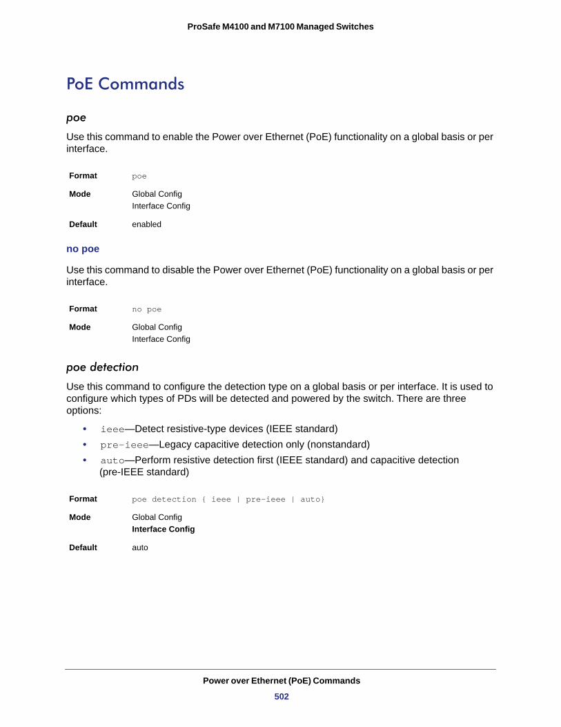
ProSafe M4100 and M7100 Managed Switches
PoE Commands
poe
Use this command to enable the Power over Ethernet (PoE) functionality on a global basis or per interface.
no poe
Use this command to disable the Power over Ethernet (PoE) functionality on a global basis or per interface.
poe detection
Use this command to configure the detection type on a global basis or per interface. It is used to configure which types of PDs will be detected and powered by the switch. There are three options:
• ieee—Detect resistive-type devices (IEEE standard)• pre-ieee—Legacy capacitive detection only (nonstandard)• auto—Perform resistive detection first (IEEE standard) and capacitive detection
(pre-IEEE standard)
Format poe
Mode Global ConfigInterface Config
Default enabled
Format no poe
Mode Global ConfigInterface Config
Format poe detection { ieee | pre-ieee | auto}
Mode Global ConfigInterface Config
Default auto
Power over Ethernet (PoE) Commands
502
ProSafe M4100 and M7100 Managed Switches
no poe detection
Use this command to set the detection mode to the default on a global basis or per interface.
poe high-power
Use this command to switch a port from 802.3af mode to high-power mode. This mode is used to power up devices that require more power than the current IEEE 802.3af power (more than 12.95 watts at the PD). There are three options:
• legacy—Use this mode if the device can power up (more than 12.95 watts) with higher current and it cannot identify itself as a Class 4 device.
• Pre-dot3at—Use this mode if the device cannot identify itself as a Class 4 device and it does not have LLDP support.
• Dot3at—Use this mode if the device is a Class 4 device capable of figuring out power requirements through 2-event classification or LLDP.
no poe high-power
Use this command to disable the high-power mode. The port will support only IEEE 902.3af devices.
This command works on a global basis or per interface.
poe power limit
Use this command to configure the type of power limit for a port. If the power limit type is “user-defined,” the command also allows you to configure a maximum power limit.
There are three options:
• class-based—Allows the port to draw up to the maximum power based on the classification of the device connected.
• none—Allows the port to draw up to Class 0 maximum power if it is in low-power mode and up to Class 4 maximum power if it is in high-power mode.
Format no poe detection
Mode Global ConfigInterface Config
Format poe high-power {legacy | pre-dot3at | dot3at}
Mode Interface Config
Default dot3at
Format no poe high-power
Mode Interface Config
Power over Ethernet (PoE) Commands
503
ProSafe M4100 and M7100 Managed Switches
• user-defined—Allows you to define the maximum power to the port. This can be a value from 3 through 32 watts.
no poe power limit
Use this command to set the power limit type to the default. It also sets the maximum power limit to the default if the power limit type is user-defined.
poe power management
Use this command to configure the power management mode based on each individual PoE unit or on all PoE units.
Both the power management modes mentioned here will power up a device based on first come, first served. When the available power is less than the power limit defined on a port, no more power will be delivered.
Static and dynamic modes differ in how the available power is calculated, as follows:
Static Power Management
Available power = power limit of the source - total allocated power
Where total allocated power is calculated as the power limit configured on the port.
Dynamic Power Management
Available power = power limit of the source - total allocated power
Where total allocated power is calculated as the amount of power consumed by the port.
For example:
Assume that the power limit of the source is 300 watts. One port is powered up and is drawing 3 watts of power. The power limit defined on the port is user-defined as 15 watts. In this case, the available power for static and dynamic would be as follows:
Static Power Management
Available power = 300 watts - 15 watts = 285 watts
Format poe power limit { class-based | none | user-defined [<3000 - 32000>] }
Mode Global Config Interface Config
Default User-defined, with a maximum of 30 watts
Format no poe power limit [user-defined]
Mode Global Config Interface Config
Power over Ethernet (PoE) Commands
504
ProSafe M4100 and M7100 Managed Switches
Dynamic Power Management
Available power = 300 watts - 3 watts = 297 watts
no poe power management
Use this command to set the power management mode to the default.
poe priority
Use this command to configure the priority on a specific port. This is used for power management purposes. The switch might not be able to supply power to all connected devices, so the port priority is used to determine which ports will supply power if adequate power capacity is not available for all enabled ports. For ports that have the same priority level, the lower numbered port will have higher priority. There are three options:
• Crit—Critical priority• High—High priority• Low—Low priority
no poe priority
Use this command to set the priority to the default.
poe reset
Use this command to reset the PoE state of every port (in global mode) or a specific port (in interface mode). When the PoE port status is shown to be in an error state, this command can be used to reset the PoE port. The command can also reset the power-delivering ports. Note that
Format poe power management {<unit>|all} {dynamic | static}
Mode Global Config
Default dynamic
Format no poe power management {<unit>|all}
Mode Global Config
Format poe priority { Crit | High | Low }
Mode Global Config Interface Config
Default low
Format no poe priority
Mode Global Config Interface Config
Power over Ethernet (PoE) Commands
505
ProSafe M4100 and M7100 Managed Switches
this command takes effect only once after it is executed and cannot be saved across power cycles.
poe timer schedule name
Use this command to allow you to attach a timer schedule to a PoE port.
You can define a time schedule using the existing time range commands. This schedule has start and stop times. When this timer schedule is applied to a PoE-enabled port, the capability of the port to deliver power is affected. At the scheduled start time, the PoE port is disabled such that it cannot deliver any power. At the scheduled stop time, the PoE port is reenabled so that it can deliver power.
Note: For information about creating a timer schedule, see Time Range Commands for Time-Based ACLs on page 488.
Format poe reset
Mode Global Config Interface Config
Format poe timer schedule <name>
Mode Interface Config
Power over Ethernet (PoE) Commands
506
ProSafe M4100 and M7100 Managed Switches
no poe timer schedule name
Use this command to detach the schedule from the port.
poe usagethreshold
Use this command to set a threshold (as a percentage) for the total amount of power that can be delivered by the switch. For example, if the switch can deliver up to a maximum of 300 watts, a usage threshold of 90% ensures that only 270 watts are used for delivering power to devices. This ensures that more power is not drawn than the switch can provide.
When the usage threshold is set, all the PDs are brought down and then brought back up. If the consumed power is less than the threshold power (in the preceding case, 270 watts), then the devices continue to power up. If the consumed power is 269 watts or less, the next device is powered up. The moment consumed power exceeds the threshold power (270 watts), no other devices can power up.
This command allows you to set the usage threshold based on each individual PoE unit or all PoE units.
no poe usagethreshold
Use this command to set the usage threshold to a default value.
poe traps
Use this command to enable logging of specific PoE-related events, such as a PoE port powering a device, the threshold being exceeded, and so on.
Format no poe timer schedule
Mode Interface Config
Format poe usagethreshold {<unit>|all} <1-99>
Mode Global Config
Default 90
Format no poe usagethreshold {<unit>|all}
Mode Global Config
Format poe traps
Mode Global Config
Default Enable
Power over Ethernet (PoE) Commands
507
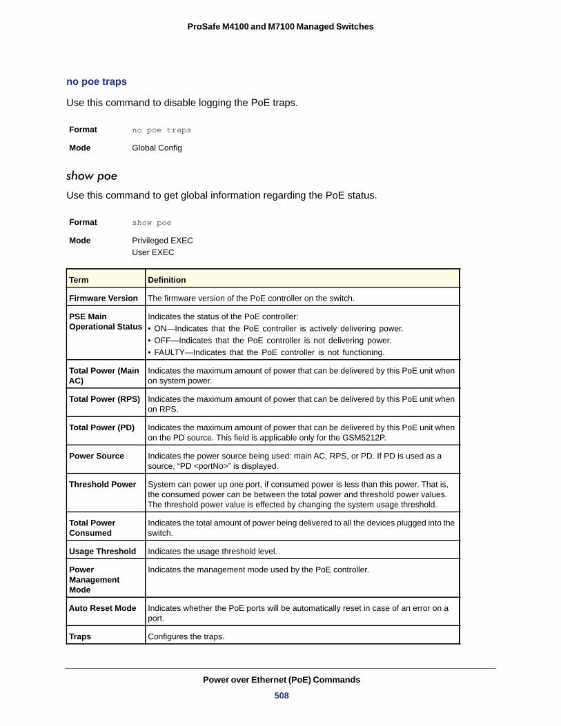
ProSafe M4100 and M7100 Managed Switches
no poe traps
Use this command to disable logging the PoE traps.
show poe
Use this command to get global information regarding the PoE status.
• ON—Indicates that the PoE controller is actively delivering power.• OFF—Indicates that the PoE controller is not delivering power.• FAULTY—Indicates that the PoE controller is not functioning.
Format no poe traps
Mode Global Config
Format show poe
Mode Privileged EXEC User EXEC
Term Definition
Firmware Version The firmware version of the PoE controller on the switch.
PSE Main Operational Status
Indicates the status of the PoE controller:
Total Power (Main AC)
Indicates the maximum amount of power that can be delivered by this PoE unit when on system power.
Total Power (RPS) Indicates the maximum amount of power that can be delivered by this PoE unit when on RPS.
Total Power (PD) Indicates the maximum amount of power that can be delivered by this PoE unit when on the PD source. This field is applicable only for the GSM5212P.
Power Source Indicates the power source being used: main AC, RPS, or PD. If PD is used as a source, “PD <portNo>” is displayed.
Threshold Power System can power up one port, if consumed power is less than this power. That is, the consumed power can be between the total power and threshold power values. The threshold power value is effected by changing the system usage threshold.
Total Power Consumed
Indicates the total amount of power being delivered to all the devices plugged into the switch.
Usage Threshold Indicates the usage threshold level.
Power Management Mode
Indicates the management mode used by the PoE controller.
Auto Reset Mode Indicates whether the PoE ports will be automatically reset in case of an error on a port.
Traps Configures the traps.
Power over Ethernet (PoE) Commands
508
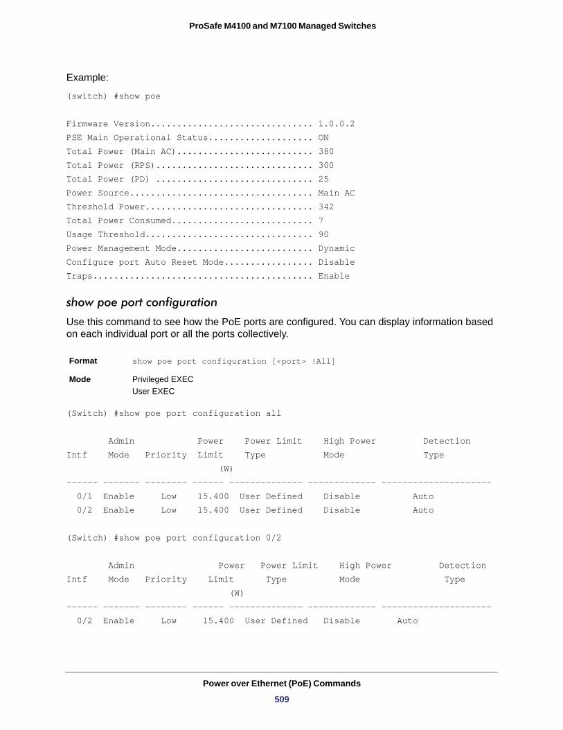
ProSafe M4100 and M7100 Managed Switches
Example:
(switch) #show poe
Firmware Version............................... 1.0.0.2PSE Main Operational Status.................... ONTotal Power (Main AC).......................... 380Total Power (RPS).............................. 300Total Power (PD) .............................. 25Power Source................................... Main ACThreshold Power................................ 342Total Power Consumed........................... 7Usage Threshold................................ 90Power Management Mode.......................... DynamicConfigure port Auto Reset Mode................. DisableTraps.......................................... Enable
show poe port configuration
Use this command to see how the PoE ports are configured. You can display information based on each individual port or all the ports collectively.
(Switch) #show poe port configuration all
Admin Power Power Limit High Power DetectionIntf Mode Priority Limit Type Mode Type (W)------ ------- -------- ------ -------------- ------------- --------------------- 0/1 Enable Low 15.400 User Defined Disable Auto 0/2 Enable Low 15.400 User Defined Disable Auto
(Switch) #show poe port configuration 0/2
Admin Power Power Limit High Power DetectionIntf Mode Priority Limit Type Mode Type (W)------ ------- -------- ------ -------------- ------------- --------------------- 0/2 Enable Low 15.400 User Defined Disable Auto
Format show poe port configuration [<port> |All]
Mode Privileged EXEC User EXEC
Power over Ethernet (PoE) Commands
509
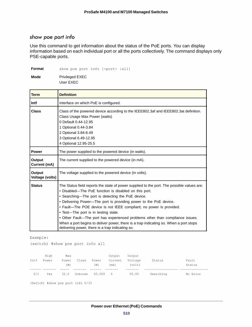
ProSafe M4100 and M7100 Managed Switches
show poe port info
Use this command to get information about the status of the PoE ports. You can display information based on each individual port or all the ports collectively. The command displays only PSE-capable ports.
• Disabled—The PoE function is disabled on this port.• Searching—The port is detecting the PoE device.• Delivering Power—The port is providing power to the PoE device.• Fault—The POE device is not IEEE compliant; no power is provided.• Test—The port is in testing state.• Other Fault—The port has experienced problems other than compliance issues.
Example:(switch) #show poe port info all
High Max Output OutputIntf Power Power Class Power Current Voltage Status Fault (W) (W) (mA) (volt) Status------ ------- ----- ------- ------ ------- ------- ------------------ --------------- 0/1 Yes 32.0 Unknown 00.000 0 00.00 Searching No Error
(Switch) #show poe port info 0/33
Format show poe port info [<port> |all]
Mode Privileged EXECUser EXEC
Term Definition
Intf Interface on which PoE is configured.
Class Class of the powered device according to the IEEE802.3af and IEEE802.3at definition.Class Usage Max Power (watts)0 Default 0.44-12.951 Optional 0.44-3.842 Optional 3.84-6.493 Optional 6.49-12.954 Optional 12.95-25.5
Power The power supplied to the powered device (in watts).
Output Current (mA)
The current supplied to the powered device (in mA).
Output Voltage (volts)
The voltage supplied to the powered device (in volts).
Status The Status field reports the state of power supplied to the port. The possible values are:
When a port begins to deliver power, there is a trap indicating so. When a port stops delivering power, there is a trap indicating so.
Power over Ethernet (PoE) Commands
510
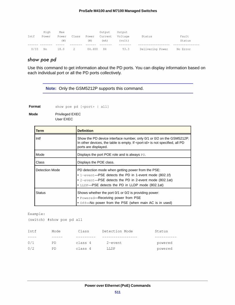
ProSafe M4100 and M7100 Managed Switches
High Max Output OutputIntf Power Power Class Power Current Voltage Status Fault (W) (W) (mA) (volt) Status------ ------- ----- ------- ------ ------- ------- ------------------ --------------- 0/33 No 18.0 2 04.400 84 53.3 Delivering Power No Error
show poe pd
Use this command to get information about the PD ports. You can display information based on each individual port or all the PD ports collectively.
Note: Only the GSM5212P supports this command.
• 1-event—PSE detects the PD in 1-event mode (802.1f)• 2-event—PSE detects the PD in 2-event mode (802.1at)• LLDP—PSE detects the PD in LLDP mode (802.1at)
• Powered—Receiving power from PSE• Off—No power from the PSE (when main AC is in used)
Example:(switch) #show poe pd all
Intf Mode Class Detection Mode Status ---- ----- --------- ---------------- ---------- 0/1 PD class 4 2-event powered 0/2 PD class 4 LLDP powered
Format show poe pd [<port> | all]
Mode Privileged EXECUser EXEC
Term Definition
Intf Show the PD device interface number, only 0/1 or 0/2 on the GSM5212P. In other devices, the table is empty. If <port-id> is not specified, all PD ports are displayed.
Mode Displays the port POE role and is always PD.
Class Displays the POE class.
Detection Mode PD detection mode when getting power from the PSE:
Status Shows whether the port 0/1 or 0/2 is providing power:
Power over Ethernet (PoE) Commands
511
0
110. Utility CommandsThis chapter describes the utility commands available in the CLI.
This chapter contains the following sections:
• Auto Install Commands • Dual Image Commands • System Information and Statistics Commands • Logging Commands • Email Alerting and Mail Server Commands • System Utility and Clear Commands • Simple Network Time Protocol (SNTP) Commands • DHCP Server Commands • DNS Client Commands • Packet Capture Commands • Serviceability Packet Tracing Commands • Cable Test Command • sFlow Commands • Software License Commands • IP Address Conflict Commands • Link Local Protocol Filtering Commands (not supported on M4100 switches)• RMON Stats and History Commands • UDLD Commands
The commands in this chapter are in four functional groups:
• Show commands display switch settings, statistics, and other information.• Configuration commands configure features and options of the switch. Every switch
command has a show command that displays the configuration setting.• Copy commands transfer or save configuration and informational files to and from the
switch. • Clear commands clear some or all of the settings to factory defaults.
512
ProSafe M4100 and M7100 Managed Switches
Auto Install Commands
This section describes the Auto Install Commands. Auto Install is a software feature which provides for the configuration of a switch automatically when the device is initialized and no configuration file is found on the switch. The Auto Install process requires DHCP to be enabled by default in order for it to be completed. The downloaded config file is not automatically saved to startup-config. An administrator must explicitly issue a save request in order to save the configuration. The Auto Install process depends upon the configuration of other devices in the network, including a DHCP or BOOTP server, a TFTP server and, if necessary, a DNS server.
There are three steps to Auto Install:
1. Configuration or assignment of an IP address for the device.2. Assignment of a TFTP server.3. Obtain a configuration file for the device from the TFTP server.
show autoinstall
This command displays the status of the Auto Config process.
Format show autoinstall
Mode
AutoInstall Mode
AutoSave Modet
AutoInstall Retry Count
AutoInstall State
Example
(switch) #show autoinstallAutoInstall Mode............................... StoppedAutoSave Mode.................................. DisabledAutoInstall Persistant Mode.................... EnabledAutoInstall Retry Count........................ 3AutoInstall State.............................. Waiting for boot options
Privileged EXEC
Term Definition
The administrator mode is enabled or disabled.
If this option is enabled, the downloaded config file will be saved. Otherwise, administrator must explicitly issue a "copy running-config startup-config" command in order to save the configuration.
the number of attempts to download a configuration.
The status of the AutoInstall.
Utility Commands
513
ProSafe M4100 and M7100 Managed Switches
boot host auto-save
This command is used to enable automatically saving the downloaded configuration on the switch.
Default
Format boot host auto-save
Mode
no boot host auto-save
This command is used to disable automatically saving the downloaded configuration on the switch.
Format no boot host auto-save
Mode
boot autoinstall start
The command is used to start Auto Install on the switch. Auto Install tries to download a config file from a TFTP server.
Format boot autoinstall start
Mode
boot autoinstall stop
The command is used to A user might terminate the Auto Install process at any time prior to the downloading of the config file. This is most optimally done when the switch is disconnected from the network, or if the requisite configuration files have not been configured on TFTP servers. Termination of the Auto Install process ends further periodic requests for a host-specific file.
Format boot autoinstall stop
Mode
boot host retry-count
This command is used to set the number of attempts to download a configuration. The valid range is from 1 to 6.
Default
Format boot host retry-count <count>
Mode
Disabled
Privileged EXEC
Privileged EXEC
Privileged EXEC
Privileged EXEC
3
Privileged EXEC
Utility Commands
514
ProSafe M4100 and M7100 Managed Switches
no boot host retry-count
This command is used to reset the number to the default. The default number is 3.
Format no boot host retry-count
Mode
boot host dhcp
This command is used to enable AutoInstall on the switch for the next reboot cycle. The command does not change the current behavior of AutroInstall and saves the command to NVRAM.
Default
Format boot host dhcp
Mode
no boot host dhcp
This command is used to disable AutoInstall on the switch for the next reboot cycle. The command does not change the current behavior of AutroInstall and saves the command to NVRAM
Format no boot host dhcp
Mode
erase startup-config
Use this command to erase the text-based configuration file stored in non-volatile memory. If the switch boots and no startup-config file is found, the AutoInstall process automatically begins.
Format erase startup-config
Mode
Dual Image Commands
The software supports a dual image feature that allows the switch to have two software images in the permanent storage. You can specify which image is the active image to be loaded in subsequent reboots. This feature allows reduced down-time when you upgrade or downgrade the software.
Privileged EXEC
Enabled3
Privileged EXEC
Privileged EXEC
Privileged EXEC
Utility Commands
515
ProSafe M4100 and M7100 Managed Switches
delete
This command deletes the supplied image file from the permanent storage. The image to be deleted must be a backup image. If this image is the active image, or if this image is activated, an error message displays. The optional <unit> parameter is valid only on Stacks. Error will be returned, if this parameter is provided, on Standalone systems. In a stack, the <unit> parameter identifies the node on which this command must be executed. When this parameter is not supplied, the command is executed on all nodes in a Stack.
Format delete [<unit>] {image1 | image2}
Mode
boot system
This command activates the specified image. It will be the active-image for subsequent reboots and will be loaded by the boot loader. The current active-image is marked as the backup-image for subsequent reboots. The optional <unit> parameter is valid only in Stacking, where the unit parameter identifies the node on which this command must be executed. When this parameter is not supplied, the command is executed on all nodes in a Stack.
Format boot system [<unit>] <image-file-name>Mode
show bootvar
This command displays the version information and the activation status for the current active and backup images on the supplied unit (node) of the Stack. If you do not specify a unit number, the command displays image details for all nodes on the Stack. The command also displays any text description associated with an image. This command, when used on a Standalone system, displays the switch activation status. For a standalone system, the unit parameter is not valid.
Format show bootvar [<unit>]
Mode
filedescr
This command associates a given text description with an image. Any existing description will be replaced. For stacking, the [<unit>] parameter identifies the node on which this command must be executed. When this parameter is not supplied, the command is executed on all nodes in a Stack.
Format filedescr [<unit>] {image1 | image2} <text-description>
Mode
Privileged EXEC
Privileged EXEC
Privileged EXEC
Privileged EXEC
Utility Commands
516
ProSafe M4100 and M7100 Managed Switches
update bootcode
This command updates the bootcode (boot loader) on the switch. The bootcode is read from the active-image for subsequent reboots. The optional <unit> parameter is valid only on Stacks. Error will be returned, if this parameter is provided, on Standalone systems. For Stacking, the <unit> parameter identifies the node on which this command must be executed. When this parameter is not supplied, the command is executed on all nodes in a Stack.
Format update bootcode [<unit>]
Mode
System Information and Statistics Commands
This section describes the commands you use to view information about system features, components, and configurations.
show arp switch
This command displays the contents of the IP stack’s Address Resolution Protocol (ARP) table. The IP stack only learns ARP entries associated with the management interfaces - network or service ports. ARP entries associated with routing interfaces are not listed.
Format show arp switch
Mode
IP Address
MAC Address
Interface
show eventlog
This command displays the event log, which contains error messages from the system. The event log is not cleared on a system reset. The <unit> is the switch identifier.
Format show eventlog [<unit>]
Mode
Privileged EXEC
Privileged EXEC
Term Definition
IP address of the management interface or another device on the management network.
Hardware MAC address of that device.
For a service port the output is Management. For a network port, the output is the slot/port of the physical interface.
Privileged EXEC
Term Definition
File The file in which the event originated.
Line The line number of the event.
Utility Commands
517
ProSafe M4100 and M7100 Managed Switches
Note: Event log information is retained across a switch reset.
show hardware
This command displays inventory information for the switch.
Note: The show version command and the show hardware command display the same information. In future releases of the software, the show hardware command will not be available. For a description of the command output, see the command show version on page 518.
show version
This command displays inventory information for the switch.
Note: The show version command will replace the show hardware command in future releases of the software.
Task Id The task ID of the event.
Code The event code.
Time The time this event occurred.
Unit The unit for the event.
Format show hardware
Mode Privileged EXEC
Format show version
Mode Privileged EXEC
Term Definition
Utility Commands
518
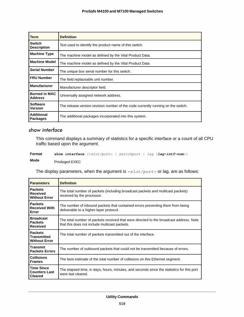
ProSafe M4100 and M7100 Managed Switches
show interface
This command displays a summary of statistics for a specific interface or a count of all CPU traffic based upon the argument.
Format show interface {<slot/port> | switchport | lag <lag-intf-num>}
Mode
The display parameters, when the argument is <slot/port> or lag, are as follows:
Packets Received Without Error
Packets Received With Error
Broadcast Packets Received
Packets Transmitted Without Error
Transmit Packets Errors
Collisions Frames
Time Since Counters Last Cleared
Term Definition
Switch Description Text used to identify the product name of this switch.
Machine Type The machine model as defined by the Vital Product Data.
Machine Model The machine model as defined by the Vital Product Data
Serial Number The unique box serial number for this switch.
FRU Number The field replaceable unit number.
Manufacturer Manufacturer descriptor field.
Burned in MAC Address Universally assigned network address.
Software Version The release.version.revision number of the code currently running on the switch.
Additional Packages The additional packages incorporated into this system.
Privileged EXEC
Parameters Definition
The total number of packets (including broadcast packets and multicast packets) received by the processor.
The number of inbound packets that contained errors preventing them from being deliverable to a higher-layer protocol.
The total number of packets received that were directed to the broadcast address. Note that this does not include multicast packets.
The total number of packets transmitted out of the interface.
The number of outbound packets that could not be transmitted because of errors.
The best estimate of the total number of collisions on this Ethernet segment.
The elapsed time, in days, hours, minutes, and seconds since the statistics for this port were last cleared.
Utility Commands
519
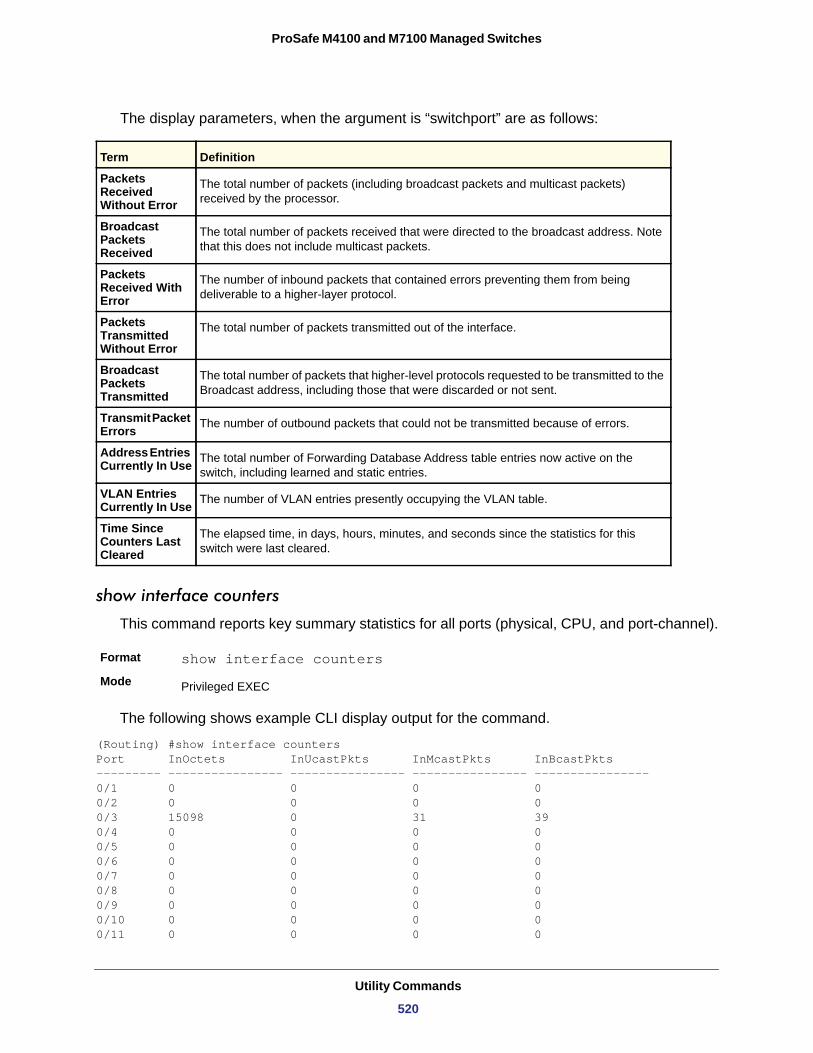
ProSafe M4100 and M7100 Managed Switches
The display parameters, when the argument is “switchport” are as follows:
Packets Received Without Error
Broadcast Packets Received
Packets Received With Error
Packets Transmitted Without Error
Broadcast Packets Transmitted
Transmit Packet Errors
Address Entries Currently In Use
VLAN Entries Currently In Use
Time Since Counters Last Cleared
show interface counters
This command reports key summary statistics for all ports (physical, CPU, and port-channel).
Format show interface counters
Mode
The following shows example CLI display output for the command.
(Routing) #show interface counters Port InOctets InUcastPkts InMcastPkts InBcastPkts--------- ---------------- ---------------- ---------------- ---------------- 0/1 0 0 0 00/2 0 0 0 00/3 15098 0 31 390/4 0 0 0 00/5 0 0 0 00/6 0 0 0 00/7 0 0 0 00/8 0 0 0 00/9 0 0 0 00/10 0 0 0 00/11 0 0 0 0
Term Definition
The total number of packets (including broadcast packets and multicast packets) received by the processor.
The total number of packets received that were directed to the broadcast address. Note that this does not include multicast packets.
The number of inbound packets that contained errors preventing them from being deliverable to a higher-layer protocol.
The total number of packets transmitted out of the interface.
The total number of packets that higher-level protocols requested to be transmitted to the Broadcast address, including those that were discarded or not sent.
The number of outbound packets that could not be transmitted because of errors.
The total number of Forwarding Database Address table entries now active on the switch, including learned and static entries.
The number of VLAN entries presently occupying the VLAN table.
The elapsed time, in days, hours, minutes, and seconds since the statistics for this switch were last cleared.
Privileged EXEC
Utility Commands
520
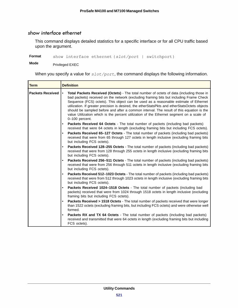
ProSafe M4100 and M7100 Managed Switches
show interface ethernet
This command displays detailed statistics for a specific interface or for all CPU traffic based upon the argument.
Format show interface ethernet {slot/port | switchport}Mode
When you specify a value for slot/port, the command displays the following information.
Privileged EXEC
Term Definition
Packets Received • Total Packets Received (Octets) - The total number of octets of data (including those in bad packets) received on the network (excluding framing bits but including Frame Check Sequence (FCS) octets). This object can be used as a reasonable estimate of Ethernet utilization. If greater precision is desired, the etherStatsPkts and etherStatsOctets objects should be sampled before and after a common interval. The result of this equation is the value Utilization which is the percent utilization of the Ethernet segment on a scale of 0–100 percent.
• Packets Received 64 Octets - The total number of packets (including bad packets) received that were 64 octets in length (excluding framing bits but including FCS octets).
• Packets Received 65–127 Octets - The total number of packets (including bad packets) received that were from 65 through 127 octets in length inclusive (excluding framing bits but including FCS octets).
• Packets Received 128–255 Octets - The total number of packets (including bad packets) received that were from 128 through 255 octets in length inclusive (excluding framing bits but including FCS octets).
• Packets Received 256–511 Octets - The total number of packets (including bad packets) received that were from 256 through 511 octets in length inclusive (excluding framing bits but including FCS octets).
• Packets Received 512–1023 Octets - The total number of packets (including bad packets) received that were from 512 through 1023 octets in length inclusive (excluding framing bits but including FCS octets).
• Packets Received 1024–1518 Octets - The total number of packets (including bad packets) received that were from 1024 through 1518 octets in length inclusive (excluding framing bits but including FCS octets).
• Packets Received > 1518 Octets - The total number of packets received that were longer than 1522 octets (excluding framing bits, but including FCS octets) and were otherwise well formed.
• Packets RX and TX 64 Octets - The total number of packets (including bad packets) received and transmitted that were 64 octets in length (excluding framing bits but including FCS octets).
Utility Commands
521
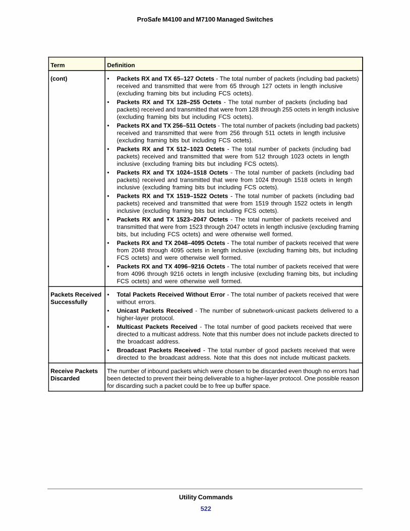
ProSafe M4100 and M7100 Managed Switches
(cont) • Packets RX and TX 65–127 Octets - The total number of packets (including bad packets) received and transmitted that were from 65 through 127 octets in length inclusive (excluding framing bits but including FCS octets).
• Packets RX and TX 128–255 Octets - The total number of packets (including bad packets) received and transmitted that were from 128 through 255 octets in length inclusive (excluding framing bits but including FCS octets).
• Packets RX and TX 256–511 Octets - The total number of packets (including bad packets) received and transmitted that were from 256 through 511 octets in length inclusive (excluding framing bits but including FCS octets).
• Packets RX and TX 512–1023 Octets - The total number of packets (including bad packets) received and transmitted that were from 512 through 1023 octets in length inclusive (excluding framing bits but including FCS octets).
• Packets RX and TX 1024–1518 Octets - The total number of packets (including bad packets) received and transmitted that were from 1024 through 1518 octets in length inclusive (excluding framing bits but including FCS octets).
• Packets RX and TX 1519–1522 Octets - The total number of packets (including bad packets) received and transmitted that were from 1519 through 1522 octets in length inclusive (excluding framing bits but including FCS octets).
• Packets RX and TX 1523–2047 Octets - The total number of packets received and transmitted that were from 1523 through 2047 octets in length inclusive (excluding framing bits, but including FCS octets) and were otherwise well formed.
• Packets RX and TX 2048–4095 Octets - The total number of packets received that were from 2048 through 4095 octets in length inclusive (excluding framing bits, but including FCS octets) and were otherwise well formed.
• Packets RX and TX 4096–9216 Octets - The total number of packets received that were from 4096 through 9216 octets in length inclusive (excluding framing bits, but including FCS octets) and were otherwise well formed.
Packets Received Successfully
• Total Packets Received Without Error - The total number of packets received that were without errors.
• Unicast Packets Received - The number of subnetwork-unicast packets delivered to a higher-layer protocol.
• Multicast Packets Received - The total number of good packets received that were directed to a multicast address. Note that this number does not include packets directed to the broadcast address.
• Broadcast Packets Received - The total number of good packets received that were directed to the broadcast address. Note that this does not include multicast packets.
Receive Packets Discarded
The number of inbound packets which were chosen to be discarded even though no errors had been detected to prevent their being deliverable to a higher-layer protocol. One possible reason for discarding such a packet could be to free up buffer space.
Term Definition
Utility Commands
522
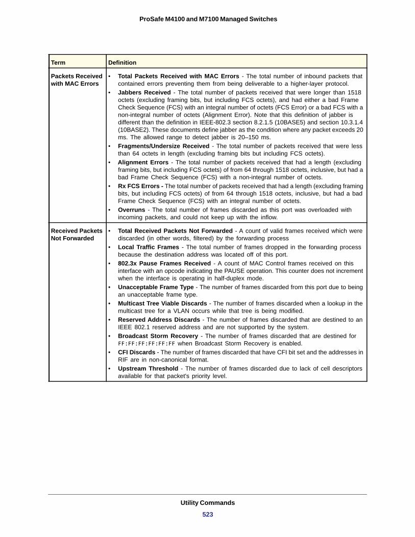
ProSafe M4100 and M7100 Managed Switches
Packets Received with MAC Errors
• Total Packets Received with MAC Errors - The total number of inbound packets that contained errors preventing them from being deliverable to a higher-layer protocol.
• Jabbers Received - The total number of packets received that were longer than 1518 octets (excluding framing bits, but including FCS octets), and had either a bad Frame Check Sequence (FCS) with an integral number of octets (FCS Error) or a bad FCS with a non-integral number of octets (Alignment Error). Note that this definition of jabber is different than the definition in IEEE-802.3 section 8.2.1.5 (10BASE5) and section 10.3.1.4 (10BASE2). These documents define jabber as the condition where any packet exceeds 20 ms. The allowed range to detect jabber is 20–150 ms.
• Fragments/Undersize Received - The total number of packets received that were less than 64 octets in length (excluding framing bits but including FCS octets).
• Alignment Errors - The total number of packets received that had a length (excluding framing bits, but including FCS octets) of from 64 through 1518 octets, inclusive, but had a bad Frame Check Sequence (FCS) with a non-integral number of octets.
• Rx FCS Errors - The total number of packets received that had a length (excluding framing bits, but including FCS octets) of from 64 through 1518 octets, inclusive, but had a bad Frame Check Sequence (FCS) with an integral number of octets.
• Overruns - The total number of frames discarded as this port was overloaded with incoming packets, and could not keep up with the inflow.
Received Packets Not Forwarded
• Total Received Packets Not Forwarded - A count of valid frames received which were discarded (in other words, filtered) by the forwarding process
• Local Traffic Frames - The total number of frames dropped in the forwarding process because the destination address was located off of this port.
• 802.3x Pause Frames Received - A count of MAC Control frames received on this interface with an opcode indicating the PAUSE operation. This counter does not increment when the interface is operating in half-duplex mode.
• Unacceptable Frame Type - The number of frames discarded from this port due to being an unacceptable frame type.
• Multicast Tree Viable Discards - The number of frames discarded when a lookup in the multicast tree for a VLAN occurs while that tree is being modified.
• Reserved Address Discards - The number of frames discarded that are destined to an IEEE 802.1 reserved address and are not supported by the system.
• Broadcast Storm Recovery - The number of frames discarded that are destined for FF:FF:FF:FF:FF:FF when Broadcast Storm Recovery is enabled.
• CFI Discards - The number of frames discarded that have CFI bit set and the addresses in RIF are in non-canonical format.
• Upstream Threshold - The number of frames discarded due to lack of cell descriptors available for that packet's priority level.
Term Definition
Utility Commands
523
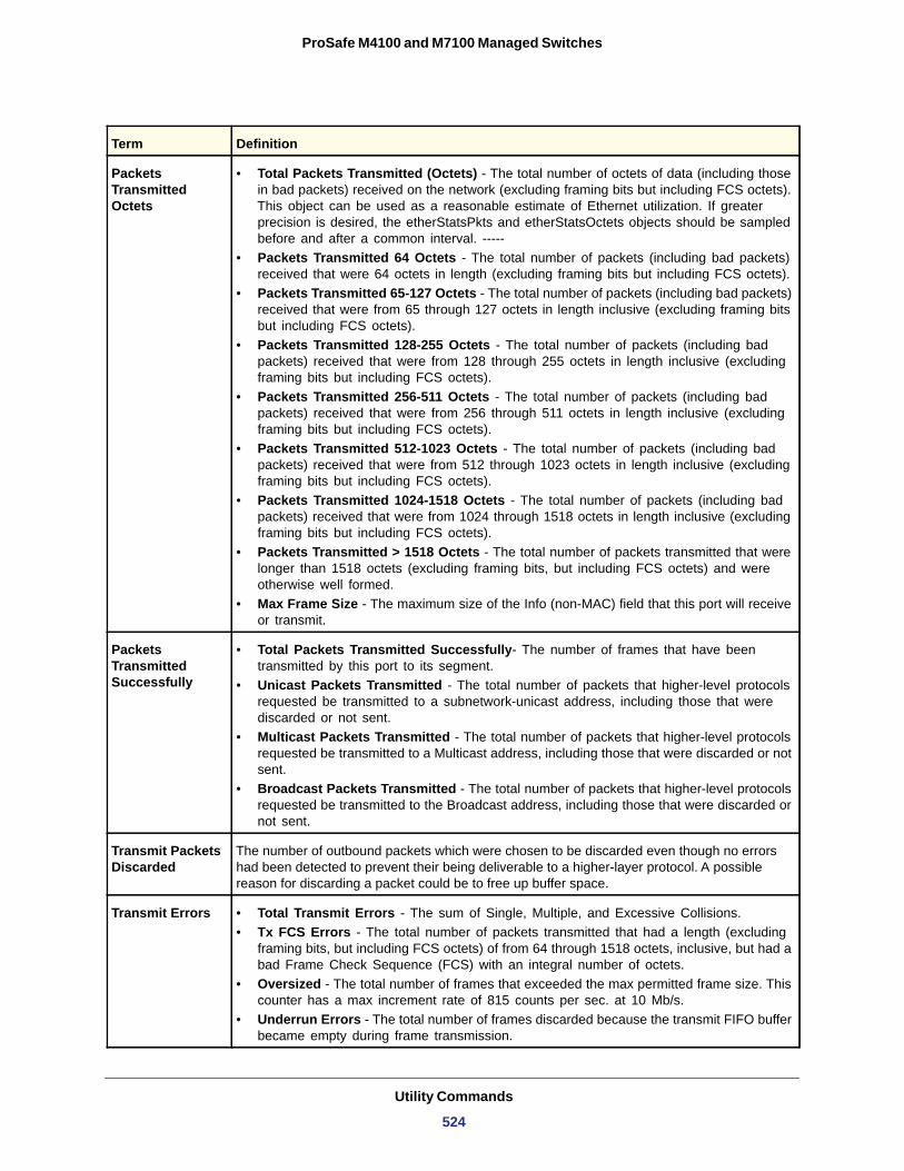
ProSafe M4100 and M7100 Managed Switches
Packets Transmitted Octets
• Total Packets Transmitted (Octets) - The total number of octets of data (including those in bad packets) received on the network (excluding framing bits but including FCS octets). This object can be used as a reasonable estimate of Ethernet utilization. If greater precision is desired, the etherStatsPkts and etherStatsOctets objects should be sampled before and after a common interval. -----
• Packets Transmitted 64 Octets - The total number of packets (including bad packets) received that were 64 octets in length (excluding framing bits but including FCS octets).
• Packets Transmitted 65-127 Octets - The total number of packets (including bad packets) received that were from 65 through 127 octets in length inclusive (excluding framing bits but including FCS octets).
• Packets Transmitted 128-255 Octets - The total number of packets (including bad packets) received that were from 128 through 255 octets in length inclusive (excluding framing bits but including FCS octets).
• Packets Transmitted 256-511 Octets - The total number of packets (including bad packets) received that were from 256 through 511 octets in length inclusive (excluding framing bits but including FCS octets).
• Packets Transmitted 512-1023 Octets - The total number of packets (including bad packets) received that were from 512 through 1023 octets in length inclusive (excluding framing bits but including FCS octets).
• Packets Transmitted 1024-1518 Octets - The total number of packets (including bad packets) received that were from 1024 through 1518 octets in length inclusive (excluding framing bits but including FCS octets).
• Packets Transmitted > 1518 Octets - The total number of packets transmitted that were longer than 1518 octets (excluding framing bits, but including FCS octets) and were otherwise well formed.
• Max Frame Size - The maximum size of the Info (non-MAC) field that this port will receive or transmit.
Packets Transmitted Successfully
• Total Packets Transmitted Successfully- The number of frames that have been transmitted by this port to its segment.
• Unicast Packets Transmitted - The total number of packets that higher-level protocols requested be transmitted to a subnetwork-unicast address, including those that were discarded or not sent.
• Multicast Packets Transmitted - The total number of packets that higher-level protocols requested be transmitted to a Multicast address, including those that were discarded or not sent.
• Broadcast Packets Transmitted - The total number of packets that higher-level protocols requested be transmitted to the Broadcast address, including those that were discarded or not sent.
Transmit Packets Discarded
The number of outbound packets which were chosen to be discarded even though no errors had been detected to prevent their being deliverable to a higher-layer protocol. A possible reason for discarding a packet could be to free up buffer space.
Transmit Errors • Total Transmit Errors - The sum of Single, Multiple, and Excessive Collisions. • Tx FCS Errors - The total number of packets transmitted that had a length (excluding
framing bits, but including FCS octets) of from 64 through 1518 octets, inclusive, but had a bad Frame Check Sequence (FCS) with an integral number of octets.
• Oversized - The total number of frames that exceeded the max permitted frame size. This counter has a max increment rate of 815 counts per sec. at 10 Mb/s.
• Underrun Errors - The total number of frames discarded because the transmit FIFO buffer became empty during frame transmission.
Term Definition
Utility Commands
524
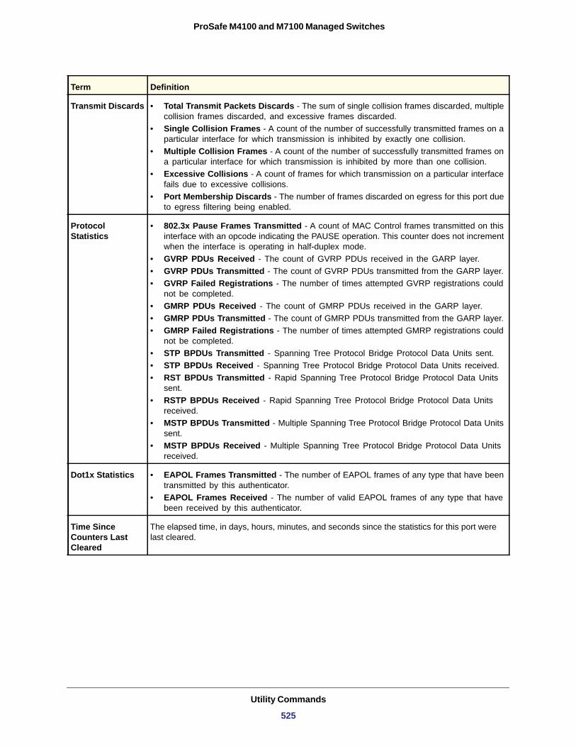
ProSafe M4100 and M7100 Managed Switches
Transmit Discards • Total Transmit Packets Discards - The sum of single collision frames discarded, multiple collision frames discarded, and excessive frames discarded.
• Single Collision Frames - A count of the number of successfully transmitted frames on a particular interface for which transmission is inhibited by exactly one collision.
• Multiple Collision Frames - A count of the number of successfully transmitted frames on a particular interface for which transmission is inhibited by more than one collision.
• Excessive Collisions - A count of frames for which transmission on a particular interface fails due to excessive collisions.
• Port Membership Discards - The number of frames discarded on egress for this port due to egress filtering being enabled.
Protocol Statistics
• 802.3x Pause Frames Transmitted - A count of MAC Control frames transmitted on this interface with an opcode indicating the PAUSE operation. This counter does not increment when the interface is operating in half-duplex mode.
• GVRP PDUs Received - The count of GVRP PDUs received in the GARP layer.• GVRP PDUs Transmitted - The count of GVRP PDUs transmitted from the GARP layer. • GVRP Failed Registrations - The number of times attempted GVRP registrations could
not be completed. • GMRP PDUs Received - The count of GMRP PDUs received in the GARP layer. • GMRP PDUs Transmitted - The count of GMRP PDUs transmitted from the GARP layer. • GMRP Failed Registrations - The number of times attempted GMRP registrations could
not be completed. • STP BPDUs Transmitted - Spanning Tree Protocol Bridge Protocol Data Units sent.• STP BPDUs Received - Spanning Tree Protocol Bridge Protocol Data Units received.• RST BPDUs Transmitted - Rapid Spanning Tree Protocol Bridge Protocol Data Units
sent.• RSTP BPDUs Received - Rapid Spanning Tree Protocol Bridge Protocol Data Units
received.• MSTP BPDUs Transmitted - Multiple Spanning Tree Protocol Bridge Protocol Data Units
sent.• MSTP BPDUs Received - Multiple Spanning Tree Protocol Bridge Protocol Data Units
received.
Dot1x Statistics • EAPOL Frames Transmitted - The number of EAPOL frames of any type that have been transmitted by this authenticator.
• EAPOL Frames Received - The number of valid EAPOL frames of any type that have been received by this authenticator.
Time Since Counters Last Cleared
The elapsed time, in days, hours, minutes, and seconds since the statistics for this port were last cleared.
Term Definition
Utility Commands
525
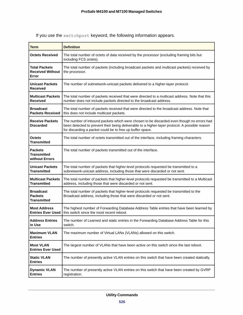
ProSafe M4100 and M7100 Managed Switches
If you use the switchport keyword, the following information appears.
Term Definition
Octets Received The total number of octets of data received by the processor (excluding framing bits but including FCS octets).
Total Packets Received Without Error
The total number of packets (including broadcast packets and multicast packets) received by the processor.
Unicast Packets Received
The number of subnetwork-unicast packets delivered to a higher-layer protocol.
Multicast Packets Received
The total number of packets received that were directed to a multicast address. Note that this number does not include packets directed to the broadcast address.
Broadcast Packets Received
The total number of packets received that were directed to the broadcast address. Note that this does not include multicast packets.
Receive Packets Discarded
The number of inbound packets which were chosen to be discarded even though no errors had been detected to prevent their being deliverable to a higher-layer protocol. A possible reason for discarding a packet could be to free up buffer space.
Octets Transmitted
The total number of octets transmitted out of the interface, including framing characters.
Packets Transmitted without Errors
The total number of packets transmitted out of the interface.
Unicast Packets Transmitted
The total number of packets that higher-level protocols requested be transmitted to a subnetwork-unicast address, including those that were discarded or not sent.
Multicast Packets Transmitted
The total number of packets that higher-level protocols requested be transmitted to a Multicast address, including those that were discarded or not sent.
Broadcast Packets Transmitted
The total number of packets that higher-level protocols requested be transmitted to the Broadcast address, including those that were discarded or not sent.
Most Address Entries Ever Used
The highest number of Forwarding Database Address Table entries that have been learned by this switch since the most recent reboot.
Address Entries in Use
The number of Learned and static entries in the Forwarding Database Address Table for this switch.
Maximum VLAN Entries
The maximum number of Virtual LANs (VLANs) allowed on this switch.
Most VLAN Entries Ever Used
The largest number of VLANs that have been active on this switch since the last reboot.
Static VLAN Entries
The number of presently active VLAN entries on this switch that have been created statically.
Dynamic VLAN Entries
The number of presently active VLAN entries on this switch that have been created by GVRP registration.
Utility Commands
526
ProSafe M4100 and M7100 Managed Switches
show mac-addr-table
This command displays the forwarding database entries. These entries are used by the transparent bridging function to determine how to forward a received frame.
Enter all or no parameter to display the entire table. Enter a MAC Address and VLAN ID to display the table entry for the requested MAC address on the specified VLAN. Enter the count parameter to view summary information about the forwarding database table. Use the interface <slot/port> parameter to view MAC addresses on a specific interface. Use the vlan <vlan_id> parameter to display information about MAC addresses on a specified VLAN.
Format show mac-addr-table [{<macaddr> <vlan_id> | all | count | interface <slot/port> | vlan <vlan_id>}]
Mode
The following information displays if you do not enter a parameter, the keyword all, or the MAC address and VLAN ID. If you enter vlan <vlan_id>, only the Mac Address, Interface, and Status fields appear.
VLAN Deletes The number of VLANs on this switch that have been created and then deleted since the last reboot.
Time Since Counters Last Cleared
The elapsed time, in days, hours, minutes, and seconds since the statistics for this switch were last cleared.
Privileged EXEC
Term Definition
Mac Address A unicast MAC address for which the switch has forwarding and or filtering information. The format is 6 or 8 two-digit hexadecimal numbers that are separated by colons, for example 01:23:45:67:89:AB. In an IVL system the MAC address will be displayed as 8 bytes.
Interface The port through which this address was learned.
Term Definition
Utility Commands
527
ProSafe M4100 and M7100 Managed Switches
If you enter the interface <slot/port> parameter, in addition to the MAC Address and Status fields, the following field appears:
VLAN ID
The following information displays if you enter the count parameter:
Dynamic Address count
Static Address (User-defined) count
Total MAC Addresses in use
Total MAC Addresses available
process cpu threshold
Use this command to configure the CPU utilization thresholds. The Rising and Falling thresholds are specified as a percentage of CPU resources. The utilization monitoring time period can be configured from 5 seconds to 86,400 seconds in multiples of 5 seconds. The CPU utilization threshold configuration is saved across a switch reboot. Configuring the
Interface Index This object indicates the ifIndex of the interface table entry associated with this port.
Status The status of this entry. The meanings of the values are:• Static. The value of the corresponding instance was added by the system or a user
when a static MAC filter was defined. It cannot be relearned.• Learned. The value of the corresponding instance was learned by observing the
source MAC addresses of incoming traffic, and is currently in use.• Management. The value of the corresponding instance (system MAC address) is also
the value of an existing instance of dot1dStaticAddress. It is identified with interface 0/1. and is currently used when enabling VLANs for routing.
• Self. The value of the corresponding instance is the address of one of the switch’s physical interfaces (the system’s own MAC address).
• GMRP Learned. The value of the corresponding was learned via GMRP and applies to Multicast.
• Other. The value of the corresponding instance does not fall into one of the other categories.
Term Definition
The VLAN on which the MAC address was learned.
Term Definition
Number of MAC addresses in the forwarding database that were automatically learned.
Number of MAC addresses in the forwarding database that were manually entered by a user.
Number of MAC addresses currently in the forwarding database.
Number of MAC addresses the forwarding database can handle.
Term Definition
Utility Commands
528
ProSafe M4100 and M7100 Managed Switches
falling utilization threshold is optional. If the falling CPU utilization parameters are not configured, they take the same value as the rising CPU utilization parameters.
Format process cpu threshold type total rising <1-100> interval <5-86400> {falling <1-100> interval <5-86400>}
Mode
show process cpu
This command provides the percentage utilization of the CPU by different tasks.
Note: It is not necessarily the traffic to the CPU, but different tasks that keep the CPU busy.
The following shows example CLI display output.
(Switch) #show process cpu Memory Utilization Report status bytes ------ ---------- free 192980480 alloc 53409968 Task Utilization Report Task Utilization ----------------------- ----------- bcmL2X.0 0.75%
Global Config
Parameter Description
rising threshold The percentage of CPU resources that, when exceeded for the configured rising interval, triggers a notification. The range is 1–100. The default is 0 (disabled).
rising interval The duration of the CPU rising threshold violation, in seconds, that must be met to trigger a notification. The range is 5–86,400. The default is 0 (disabled).
falling threshold The percentage of CPU resources that, when usage falls below this level for the configured interval, triggers a notification. The range is 1–100. The default is 0 (disabled). A notification is triggered when the total CPU utilization falls below this level for a configured period of time. The falling utilization threshold notification is made only if a rising threshold notification was previously done. The falling utilization threshold must always be equal or less than the rising threshold value. The CLI does not allow setting the falling threshold to be greater than the rising threshold.
falling interval The duration of the CPU falling threshold, in seconds, that must be met to trigger a notification. The range is 5–86,400. The default is 0 (disabled).
Format show process cpu
Mode Privileged EXEC
Utility Commands
529
ProSafe M4100 and M7100 Managed Switches
bcmCNTR.0 0.20% bcmLINK.0 0.35% DHCP snoop 0.10% Dynamic ARP Inspection 0.10% dot1s_timer_task 0.10% dhcpsPingTask 0.20%
show mbuf total
This command shows the total system buffer pools status.
Format
Mode
The following shows an example of CLI display output for the command.
(switch) #show mbuf total
mbufSize 9284 (0x2444)Current Time 0x1897faMbufsFree 150MbufsRxUsed 0Total Rx Norm Alloc Attempts 26212Total Rx Mid2 Alloc Attempts 4087Total Rx Mid1 Alloc Attempts 188943Total Rx High Alloc Attempts 384555Total Tx Alloc Attempts 2478536Total Rx Norm Alloc Failures 0Total Rx Mid2 Alloc Failures 0Total Rx Mid1 Alloc Failures 0Total Rx High Alloc Failures 0Total Tx Alloc Failures 0
show running-config
Use this command to display or capture the current setting of different protocol packages supported on the switch. This command displays or captures commands with settings and configurations that differ from the default value. To display or capture the commands with settings and configurations that are equal to the default value, include the [all] option.
Note: Show running-config does not display the User Password, even if you set one different from the default.
The output is displayed in the script format, which can be used to configure another switch with same configuration. If the optional <scriptname> is provided with a file name extension of “.scr”, the output is redirected to a script file.
show mbuf total
Privileged EXEC
Utility Commands
530
ProSafe M4100 and M7100 Managed Switches
Note: If you issue the show running-config command from a serial connection, access to the switch through remote connections (such as Telnet) is suspended while the output is being generated and displayed.
Note: If you use a text-based configuration file, the show running-config command will only display configured physical interfaces, that is, if any interface only contains the default configuration, that interface will be skipped from the show running-config command output. This is true for any configuration mode that contains nothing but default configuration. That is, the command to enter a particular config mode, followed immediately by its ‘exit’ command, are both omitted from the show running-config command output (and hence from the startup-config file when the system configuration is saved.)
If all the flags in a particular group are enabled, the command displays trapflags <group name> all.
If some, but not all, of the flags in that group are enabled, the command displays trapflags <groupname> <flag-name>.
Format show running-config [all | <scriptname>]
Mode
show running-config interface
This command shows the current configuration on a particular interface. The interface could be a physical port or a virtual port—like a LAG or VLAN. The output captures how the configuration differs from the factory default value.
Format
Mode
show sysinfo
This command displays switch information.
Format show sysinfo Mode
Privileged EXEC
show running-config interface {<slot/port>} | VLAN <id> | LAG <id>}
Interface Config
Privileged EXEC
Utility Commands
531
ProSafe M4100 and M7100 Managed Switches
Switch Description
System Name
System Location
System Contact
System Object ID
System Up Time
MIBs Supported
show tech-support
Use this command to display system and configuration information when you contact technical support. The output of this command combines the output of the following commands:
• show version• show sysinfo• show port all• show isdp neighbors• show logging• show event log• show logging buffered• show trap log
Format show tech-support
Mode
show tech-support techsupport
This command without the techsupport parameter displays system and configuration information about the console. To generate the information in a file, specify the techsupport parameter.
Format show tech-support techsupport
Mode
Term Definition
Text used to identify this switch.
Name used to identify the switch. The factory default is blank. To configure the system name, see snmp-server on page 670.
Text used to identify the location of the switch. The factory default is blank. To configure the system location, see snmp-server on page 670.
Text used to identify a contact person for this switch. The factory default is blank. To configure the system location, see snmp-server on page 670.
The base object ID for the switch’s enterprise MIB.
The time in days, hours, and minutes since the last switch reboot.
A list of MIBs supported by this agent.
Privileged EXEC
Privileged EXEC
Utility Commands
532
ProSafe M4100 and M7100 Managed Switches
length
Use this command to set the pagination length to value number of lines for the sessions specified by configuring on different Line Config modes (telnet, ssh, and console) and is persistent.
Default
Format length <0|5-48>
Mode
no length value
Use this command to set the pagination length to the default value number of lines.
Format no length
Mode
terminal length
Use this command to set the number of lines of output to be displayed on the screen, i.e. pagination, for the show running-config and show running-config all commands. The terminal length size is either zero or a number in the range of 5–48. After the user-configured number of lines is displayed in one page, the system prompts the user “--More-- or (q)uit.” Press q or Q to quit, or press any key to display the next set of <5-48> lines. The command terminal length 0 disables pagination and, as a result, the output of the show running-config command is displayed immediately.
Default
Format terminal length <0|5-48>
Mode
no terminal length
Use this command to set the terminal length to the default value.
Format no terminal length
Mode
show terminal length
Use this command to display the value of the user-configured terminal length size.
Format show terminal length
Mode
24
Line Config
Line Config
24 lines per page
Privileged EXEC
Privileged EXEC
Privileged EXEC
Utility Commands
533
ProSafe M4100 and M7100 Managed Switches
memory free low-watermark processor
Use this command to get notifications when the CPU free memory falls below the configured threshold. A notification is generated when the free memory falls below the threshold. Another notification is generated once the available free memory rises to 10 percent above the specified threshold. To prevent generation of excessive notifications when the CPU free memory fluctuates around the configured threshold, only one Rising or Falling memory notification is generated over a period of 60 seconds. The threshold is specified in kilobytes. The CPU free memory threshold configuration is saved across a switch reboot.
Format memory free low-watermark processor <1-1034956>Mode
Logging Commands
This section describes the commands you use to configure system logging, and to view logs and the logging settings.
logging buffered
This command enables logging to an in-memory log that keeps up to 128 logs.
Default
Format logging buffered
Mode
no logging buffered
This command disables logging to in-memory log.
Format no logging buffered
Mode
Global Config
Parameter Description
low-watermark When CPU free memory falls below this threshold, a notification message is triggered. The range is 1 to the maximum available memory on the switch. The default is 0 (disabled).
disabled; critical when enabled
Global Config
Global Config
Utility Commands
534
ProSafe M4100 and M7100 Managed Switches
logging buffered wrap
This command enables wrapping of in-memory logging when the log file reaches full capacity. Otherwise when the log file reaches full capacity, logging stops.
Default
Format logging buffered wrap
Mode
no logging buffered wrap
This command disables wrapping of in-memory logging and configures logging to stop when the log file capacity is full.
Format no logging buffered wrap
Mode
logging cli-command
This command enables the CLI command logging feature, which enables the 7000 series software to log all CLI commands issued on the system.
Default
Format logging cli-command
Mode
no logging cli-command
This command disables the CLI command Logging feature.
Format no logging cli-command
Mode
logging console
This command enables logging to the console. You can specify the <severitylevel> value as either an integer from 0 to 7 or symbolically through one of the following keywords: emergency (0), alert (1), critical (2), error (3), warning (4), notice (5), info (6), or debug (7).
Default
Format logging console [severitylevel]
Mode
enabled
Privileged EXEC
Privileged EXEC
enabled
Global Config
Global Config
disabled; critical when enabled
Global Config
Utility Commands
535
ProSafe M4100 and M7100 Managed Switches
no logging console
This command disables logging to the console.
Format no logging console
Mode
logging host
This command enables logging to a host. You can configure up to eight hosts. The <ipaddr|hostname> is the IP address of the logging host. The <addresstype> indicates the type of address ipv4 or ipv6 or dns being passed. The <port> value is a port number from 1 to 65535. You can specify the <severitylevel> value as either an integer from 0 to 7 or symbolically through one of the following keywords: emergency (0), alert (1), critical (2), error (3), warning (4), notice (5), info (6), or debug (7).
The end user can configure either an IPv4 or IPv6 address or a host name for a Syslog collector among the list of servers.
Default • port—514• level—critical (2)
Format logging host <ipaddr|hostname> <addresstype> [<port>][<severitylevel>]
Mode
logging host remove
This command disables logging to host. See show logging hosts on page 538 for a list of host indexes.
Format logging host remove <hostindex>
Mode
logging syslog
This command enables syslog logging. The <portid> parameter is an integer with a range of 1-65535.
Default
Format logging syslog [port <portid>]
Mode
Global Config
Global Config
Global Config
disabled
Global Config
Utility Commands
536
ProSafe M4100 and M7100 Managed Switches
no logging syslog
This command disables syslog logging.
Format no logging syslog
Mode
logging syslog source-interface
This command configures the syslog source-interface.
Format logging syslog source-interface {<u/s/p> | {loopback <loopback-id>} | {tunnel <tunnel-id>}}
Mode
show logging
This command displays logging configuration information.
Format show logging
Mode
Logging Client Local Port
CLI Command Logging
Console Logging
Console Logging Severity Filter
Buffered Logging
Syslog Logging
Log Messages Received
Log Messages Dropped
Log Messages Relayed
Global Config
Global Config
Privileged EXEC
Term Definition
The port on the collector/relay to which syslog messages are sent.
Shows whether CLI Command logging is enabled.
Shows whether console logging is enabled.
The minimum severity to log to the console log. Messages with an equal or lower numerical severity are logged.
Shows whether buffered logging is enabled.
Shows whether syslog logging is enabled.
Number of messages received by the log process. This includes messages that are dropped or ignored.
Number of messages that could not be processed due to error or lack of resources.
Number of messages sent to the collector/relay.
Utility Commands
537
ProSafe M4100 and M7100 Managed Switches
show logging buffered
This command displays buffered logging (system startup and system operation logs).
Format show logging buffered
Mode
Buffered (In-Memory) Logging
Buffered Logging Wrapping Behavior
Buffered Log Count
show logging hosts
This command displays all configured logging hosts.
Format show logging hosts
Mode
Host Index
IP Address / Hostname
Severity Level
Port
Host Status
show logging traplogs
This command displays SNMP trap events and statistics.
Format show logging traplogs
Mode
Privileged EXEC
Term Definition
Shows whether the In-Memory log is enabled or disabled.
The behavior of the In Memory log when faced with a log full situation.
The count of valid entries in the buffered log.
Privileged EXEC
Term Definition
(Used for deleting hosts.)
IP address or hostname of the logging host.
The minimum severity to log to the specified address. The possible values are emergency (0), alert (1), critical (2), error (3), warning (4), notice (5), info (6), or debug (7).
The server port number, which is the port on the local host from which syslog messages are sent.
The state of logging to configured syslog hosts. If the status is disable, no logging occurs.
Privileged EXEC
Utility Commands
538
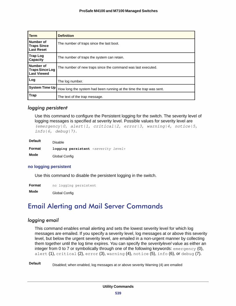
ProSafe M4100 and M7100 Managed Switches
Number of Traps Since Last Reset
Trap Log Capacity
Number of Traps Since Log Last Viewed
Log
System Time Up
Trap
logging persistent
Use this command to configure the Persistent logging for the switch. The severity level of logging messages is specified at severity level. Possible values for severity level are (emergency|0, alert|1, critical|2, error|3, warning|4, notice|5, info|6, debug|7).
Default
Format logging persistent <severity level>
Mode
no logging persistent
Use this command to disable the persistent logging in the switch.
Format no logging persistent
Mode
Email Alerting and Mail Server Commands
logging email
This command enables email alerting and sets the lowest severity level for which log messages are emailed. If you specify a severity level, log messages at or above this severity level, but below the urgent severity level, are emailed in a non-urgent manner by collecting them together until the log time expires. You can specify the severitylevel value as either an integer from 0 to 7 or symbolically through one of the following keywords: emergency (0), alert (1), critical (2), error (3), warning (4), notice (5), info (6), or debug (7).
Term Definition
The number of traps since the last boot.
The number of traps the system can retain.
The number of new traps since the command was last executed.
The log number.
How long the system had been running at the time the trap was sent.
The text of the trap message.
Disable
Global Config
Global Config
Default Disabled; when enabled, log messages at or above severity Warning (4) are emailed
Utility Commands
539
ProSafe M4100 and M7100 Managed Switches
no logging email
This command disables email alerting.
Format no logging email
Mode
logging email urgent
This command sets the lowest severity level at which log messages are emailed immediately in a single email message. Specify the severitylevel value as either an integer from 0 to 7 or symbolically through one of the following keywords: emergency (0), alert (1), critical (2), error (3), warning (4), notice (5), info (6), or debug (7). Specify none to indicate that log messages are collected and sent in a batch email at a specified interval.
Default
Format logging email urgent {<severitylevel> | none }
Mode
no logging email urgent
This command resets the urgent severity level to the default value.
Format no logging email urgent
Mode
logging email message-type to-addr
This command configures the email address to which messages are sent. The message types supported are urgent, non-urgent, and both. For each supported severity level, multiple email addresses can be configured. The to-email-addr variable is a standard email address, for example [email protected].
Format logging email message-type {urgent |non-urgent |both} to-addr <to-email-addr>
Mode
Format logging email [<severitylevel>]
Mode Global Config
Global Config
Alert (1) and emergency (0) messages are sent immediately
Global Config
Global Config
Global Config
Utility Commands
540
ProSafe M4100 and M7100 Managed Switches
no logging email message-type to-addr
This command removes the configured to-addr field of email.
Format no logging email message-type {urgent |non-urgent |both} to-addr <to-email-addr>
Mode
logging email from-addr
This command configures the email address of the sender (the switch).
Default
Format logging email from-addr <from-email-addr>
Mode
no logging email from-addr
This command removes the configured email source address.
Format no logging email from-addr <from-email-addr>
Mode
logging email message-type subject
This command configures the subject line of the email for the specified type.
Default For urgent messages: Urgent Log MessagesFor non-urgent messages: Non-Urgent Log Messages
Format logging email message-type {urgent |non-urgent |both} subject <subject>
Mode
no logging email message-type subject
This command removes the configured email subject for the specified message type and restores it to the default email subject.
Format no logging email message-type {urgent |non-urgent |both} subject
Mode
Global Config
Global Config
Global Config
Global Config
Global Config
Utility Commands
541
ProSafe M4100 and M7100 Managed Switches
logging email logtime
This command configures how frequently non-urgent email messages are sent. Non-urgent messages are collected and sent in a batch email at the specified interval. The valid range is every 30- 1440 minutes.
Default
Format logging email logtime <minutes>
Mode
no logging email logtime
This command resets the non-urgent log time to the default value.
Format no logging email logtime
Mode
logging traps
This command sets the severity at which SNMP traps are logged and sent in an email. Specify the severitylevel value as either an integer from 0 to 7 or symbolically through one of the following keywords: emergency (0), alert (1), critical (2), error (3), warning (4), notice (5), info (6), or debug (7).
Default
Format logging traps <severitylevel>
Mode
no logging traps
This command resets the SNMP trap logging severity level to the default value.
Format no logging traps
Mode
logging email test message-type
This command sends an email to the SMTP server to test the email alerting function.
Format logging email test message-type {urgent |non-urgent |both} message-body <message-body>
Mode
30 minutes
Global Config
Global Config
Info (6) messages and higher are logged.
Global Config
Global Config
Global Config
Utility Commands
542
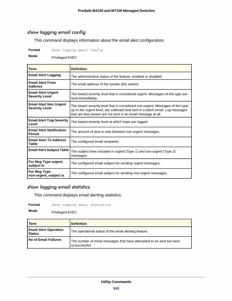
ProSafe M4100 and M7100 Managed Switches
show logging email config
This command displays information about the email alert configuration.
Format show logging email config
Mode
Email Alert Logging
Email Alert From Address
Email Alert Urgent Severity Level
Email Alert Non Urgent Severity Level
Email Alert Trap Severity Level
Email Alert Notification Period
Email Alert To Address Table
Email Alert Subject Table
For Msg Type urgent, subject is
For Msg Type non-urgent, subject is
show logging email statistics
This command displays email alerting statistics.
Format show logging email statistics
Mode
Privileged EXEC
Term Definition
The administrative status of the feature: enabled or disabled
The email address of the sender (the switch).
The lowest severity level that is considered urgent. Messages of this type are sent immediately.
The lowest severity level that is considered non-urgent. Messages of this type, up to the urgent level, are collected and sent in a batch email. Log messages that are less severe are not sent in an email message at all.
The lowest severity level at which traps are logged.
The amount of time to wait between non-urgent messages.
The configured email recipients.
The subject lines included in urgent (Type 1) and non-urgent (Type 2) messages.
The configured email subject for sending urgent messages.
The configured email subject for sending non-urgent messages.
Privileged EXEC
Term Definition
Email Alert Operation Status The operational status of the email alerting feature.
No of Email Failures The number of email messages that have attempted to be sent but were unsuccessful.
Utility Commands
543
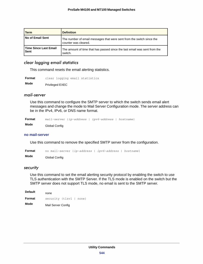
ProSafe M4100 and M7100 Managed Switches
clear logging email statistics
This command resets the email alerting statistics.
Format clear logging email statistics
Mode
mail-server
Use this command to configure the SMTP server to which the switch sends email alert messages and change the mode to Mail Server Configuration mode. The server address can be in the IPv4, IPv6, or DNS name format.
Format mail-server {ip-address | ipv6-address | hostname}
Mode
no mail-server
Use this command to remove the specified SMTP server from the configuration.
Format no mail-server {ip-address | ipv6-address | hostname}
Mode
security
Use this command to set the email alerting security protocol by enabling the switch to use TLS authentication with the SMTP Server. If the TLS mode is enabled on the switch but the SMTP server does not support TLS mode, no email is sent to the SMTP server.
Default
Format security {tlsv1 | none}
Mode
No of Email Sent The number of email messages that were sent from the switch since the counter was cleared.
Time Since Last Email Sent The amount of time that has passed since the last email was sent from the
switch.
Privileged EXEC
Global Config
Global Config
none
Mail Server Config
Term Definition
Utility Commands
544
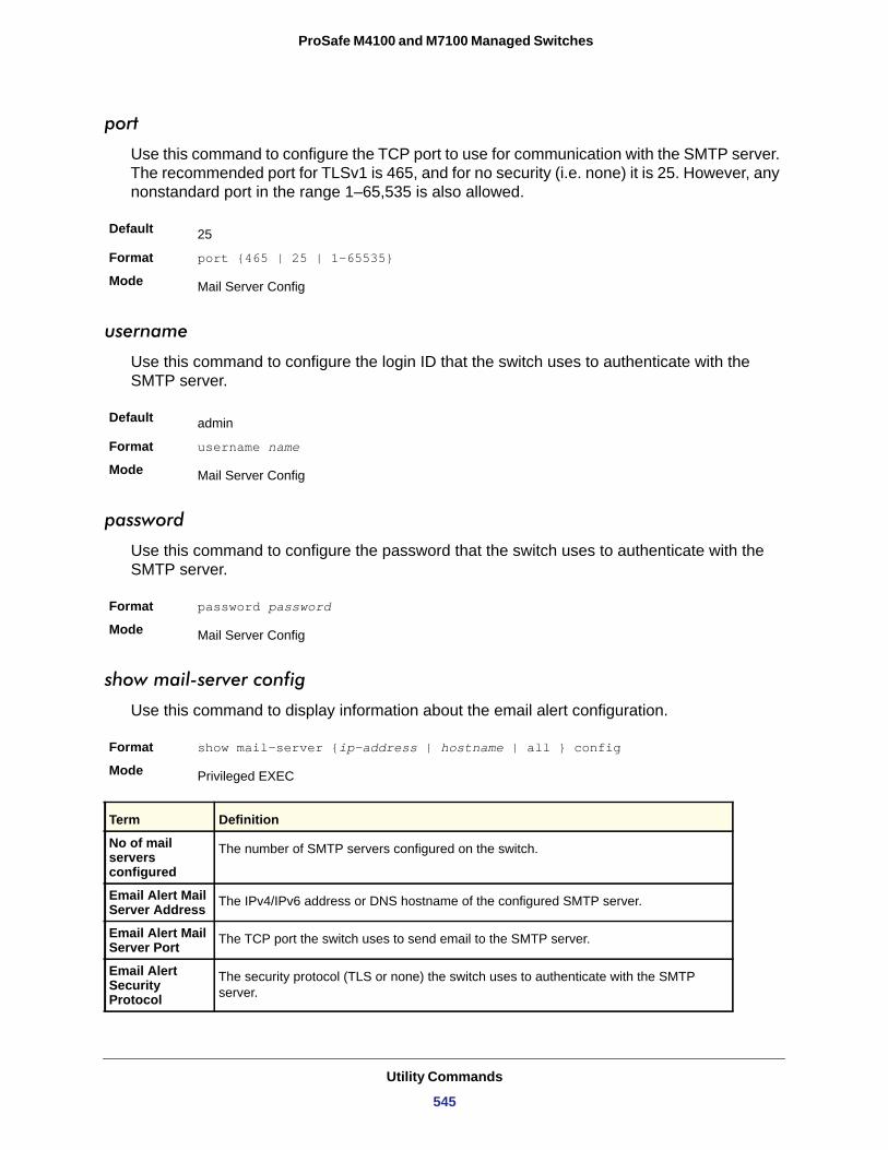
ProSafe M4100 and M7100 Managed Switches
port
Use this command to configure the TCP port to use for communication with the SMTP server. The recommended port for TLSv1 is 465, and for no security (i.e. none) it is 25. However, any nonstandard port in the range 1–65,535 is also allowed.
Default
Format port {465 | 25 | 1–65535}
Mode
username
Use this command to configure the login ID that the switch uses to authenticate with the SMTP server.
Default
Format username name
Mode
password
Use this command to configure the password that the switch uses to authenticate with the SMTP server.
Format password password
Mode
show mail-server config
Use this command to display information about the email alert configuration.
Format show mail-server {ip-address | hostname | all } config
Mode
25
Mail Server Config
admin
Mail Server Config
Mail Server Config
Privileged EXEC
Term Definition
No of mail servers configured
The number of SMTP servers configured on the switch.
Email Alert Mail Server Address The IPv4/IPv6 address or DNS hostname of the configured SMTP server.
Email Alert Mail Server Port The TCP port the switch uses to send email to the SMTP server.
Email Alert Security Protocol
The security protocol (TLS or none) the switch uses to authenticate with the SMTP server.
Utility Commands
545
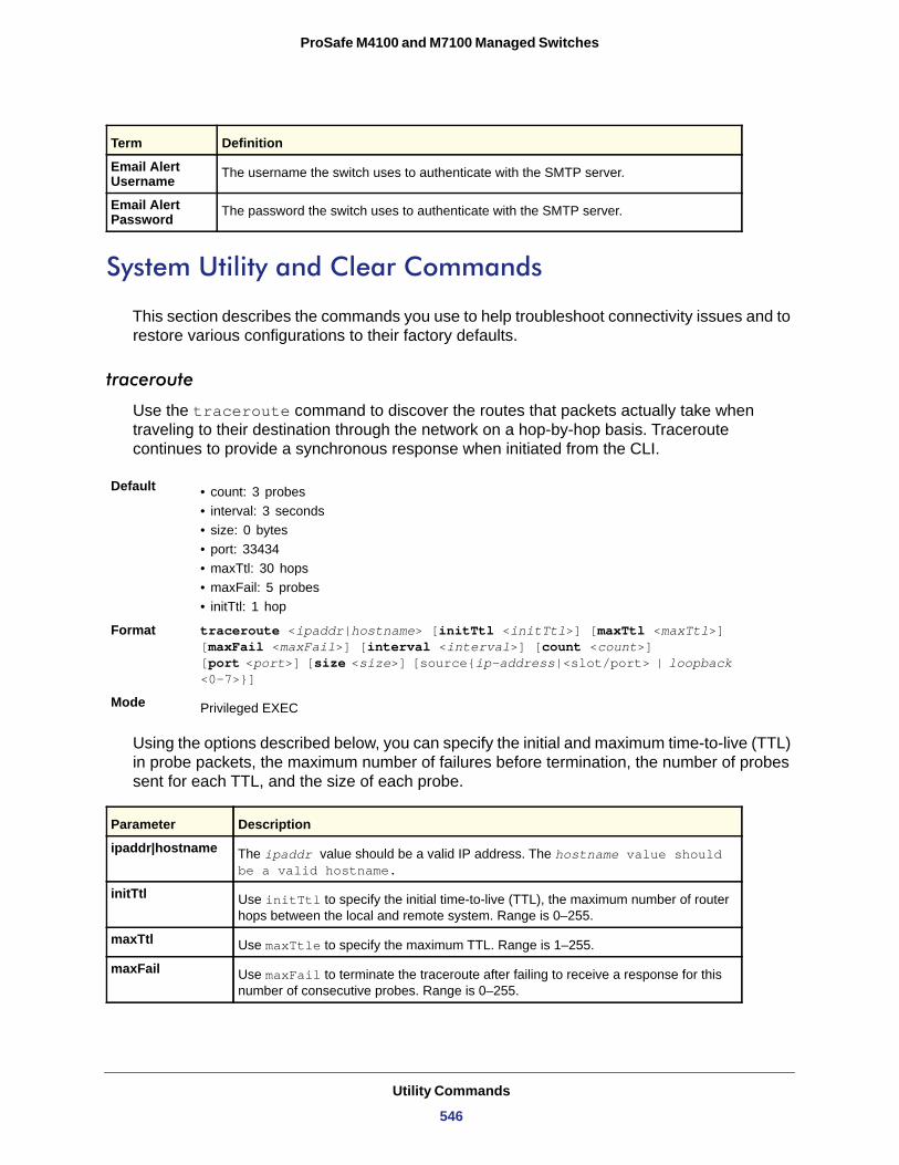
ProSafe M4100 and M7100 Managed Switches
System Utility and Clear Commands
This section describes the commands you use to help troubleshoot connectivity issues and to restore various configurations to their factory defaults.
traceroute
Use the traceroute command to discover the routes that packets actually take when traveling to their destination through the network on a hop-by-hop basis. Traceroute continues to provide a synchronous response when initiated from the CLI.
Default • count: 3 probes• interval: 3 seconds• size: 0 bytes• port: 33434• maxTtl: 30 hops• maxFail: 5 probes• initTtl: 1 hop
Format traceroute <ipaddr|hostname> [initTtl <initTtl>] [maxTtl <maxTtl>] [maxFail <maxFail>] [interval <interval>] [count <count>] [port <port>] [size <size>] [source{ip-address|<slot/port> | loopback <0-7>}]
Mode
Using the options described below, you can specify the initial and maximum time-to-live (TTL) in probe packets, the maximum number of failures before termination, the number of probes sent for each TTL, and the size of each probe.
Email Alert Username The username the switch uses to authenticate with the SMTP server.
Email Alert Password The password the switch uses to authenticate with the SMTP server.
Privileged EXEC
Parameter Description
ipaddr|hostname The ipaddr value should be a valid IP address. The hostname value should be a valid hostname.
initTtl Use initTtl to specify the initial time-to-live (TTL), the maximum number of router hops between the local and remote system. Range is 0–255.
maxTtl Use maxTtle to specify the maximum TTL. Range is 1–255.
maxFail Use maxFail to terminate the traceroute after failing to receive a response for this number of consecutive probes. Range is 0–255.
Term Definition
Utility Commands
546
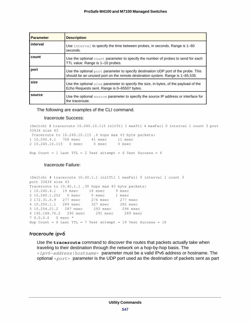
ProSafe M4100 and M7100 Managed Switches
The following are examples of the CLI command.
traceroute Success:
(Switch) # traceroute 10.240.10.115 initTtl 1 maxTtl 4 maxFail 0 interval 1 count 3 port 33434 size 43 Traceroute to 10.240.10.115 ,4 hops max 43 byte packets:1 10.240.4.1 708 msec 41 msec 11 msec2 10.240.10.115 0 msec 0 msec 0 msec
Hop Count = 1 Last TTL = 2 Test attempt = 6 Test Success = 6
traceroute Failure:
(Switch) # traceroute 10.40.1.1 initTtl 1 maxFail 0 interval 1 count 3port 33434 size 43Traceroute to 10.40.1.1 ,30 hops max 43 byte packets:1 10.240.4.1 19 msec 18 msec 9 msec2 10.240.1.252 0 msec 0 msec 1 msec3 172.31.0.9 277 msec 276 msec 277 msec4 10.254.1.1 289 msec 327 msec 282 msec5 10.254.21.2 287 msec 293 msec 296 msec6 192.168.76.2 290 msec 291 msec 289 msec7 0.0.0.0 0 msec *Hop Count = 6 Last TTL = 7 Test attempt = 19 Test Success = 18
traceroute ipv6
Use the traceroute command to discover the routes that packets actually take when traveling to their destination through the network on a hop-by-hop basis. The <ipv6-address|hostname> parameter must be a valid IPv6 address or hostname. The optional <port> parameter is the UDP port used as the destination of packets sent as part
interval Use interval to specify the time between probes, in seconds. Range is 1–60 seconds.
count Use the optional count parameter to specify the number of probes to send for each TTL value. Range is 1–10 probes.
port Use the optional port parameter to specify destination UDP port of the probe. This should be an unused port on the remote destination system. Range is 1–65,535.
size Use the optional size parameter to specify the size, in bytes, of the payload of the Echo Requests sent. Range is 0–65507 bytes.
source Use the optional source parameter to specify the source IP address or interface for the traceroute.
Parameter Description
Utility Commands
547
ProSafe M4100 and M7100 Managed Switches
of the traceroute. This port should be an unused port on the destination system. The range for <port> is zero (0) to 65535. The default value is 33434.
Default
Format traceroute ipv6 <ipv6-address|hostname> [port <port>]
Mode
clear config
This command resets the configuration to the factory defaults without powering off the switch. When you issue this command, a prompt appears to confirm that the reset should proceed. When you enter y, you automatically reset the current configuration on the switch to the default values. It does not reset the switch.
Format clear config
Mode
clear eventlog
This command clears all event messages maintained in the switch.
Format clear eventlog
Mode
clear mac-addr-table
This command clears the dynamically learned MAC addresses of the switch.
Format clear mac-addr-table
Mode
clear logging buffered
This command clears the messages maintained in the system log.
Format clear logging buffered
Mode
port: 33434
Privileged EXEC
Privileged EXEC
Privileged EXEC
Privileged EXEC
Privileged EXEC
Utility Commands
548
ProSafe M4100 and M7100 Managed Switches
clear counters
This command clears the statistics for a specified <slot/port>, for all the ports, or for the entire switch based upon the argument.
Format clear counters {<slot/port> | all}
Mode
clear igmpsnooping
This command clears the tables managed by the IGMP Snooping function and attempts to delete these entries from the Multicast Forwarding Database.
Format clear igmpsnooping
Mode
clear pass
This command resets all user passwords to the factory defaults without powering off the switch. You are prompted to confirm that the password reset should proceed.
Format clear pass
Mode
clear port-channel
This command clears all port-channels (LAGs).
Format clear port-channel
Mode
clear traplog
This command clears the trap log.
Format clear traplog
Mode
clear vlan
This command resets VLAN configuration parameters to the factory defaults.
Format clear vlan
Mode
Privileged EXEC
Privileged EXEC
Privileged EXEC
Privileged EXEC
Privileged EXEC
Privileged EXEC
Utility Commands
549
ProSafe M4100 and M7100 Managed Switches
enable password
This command prompts you to change the Privileged EXEC password. Passwords are a maximum of 64 alphanumeric characters. The password is case-sensitive. The option [encrypted] allows the administrator to transfer the enable password between devices without having to know the password. In this case, the <password> parameter must be exactly 128 hexadecimal characters.
Format enable password <password> [encrypted]
Mode
logout
This command closes the current telnet connection or resets the current serial connection.
Note: Save configuration changes before logging out.
ping
Use this command to determine whether another computer is on the network. Ping provides a synchronous response when initiated from the CLI and web interfaces.
Default • The default count is 1.• The default interval is 3 seconds.• The default size is 0 bytes.
Format ping <ipaddress|hostname> [count <count>] [interval <interval>] [size <size>]
Modes • Privileged EXEC• User EXEC
Privileged EXEC
Format logout
Modes • Privileged EXEC• User EXEC
Utility Commands
550
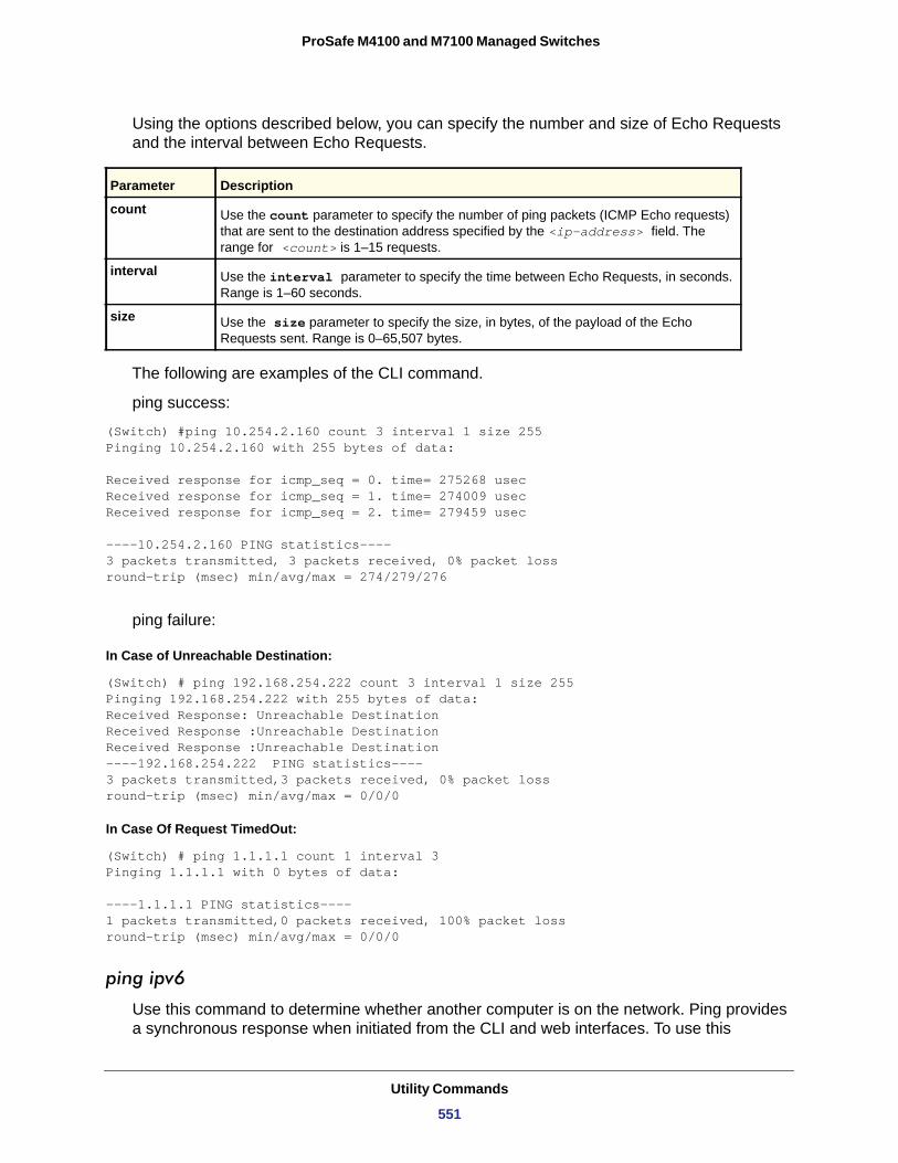
ProSafe M4100 and M7100 Managed Switches
Using the options described below, you can specify the number and size of Echo Requests and the interval between Echo Requests.
count
interval
size
The following are examples of the CLI command.
ping success:
(Switch) #ping 10.254.2.160 count 3 interval 1 size 255Pinging 10.254.2.160 with 255 bytes of data:
Received response for icmp_seq = 0. time= 275268 usecReceived response for icmp_seq = 1. time= 274009 usecReceived response for icmp_seq = 2. time= 279459 usec
----10.254.2.160 PING statistics----3 packets transmitted, 3 packets received, 0% packet lossround-trip (msec) min/avg/max = 274/279/276
ping failure:
In Case of Unreachable Destination:
(Switch) # ping 192.168.254.222 count 3 interval 1 size 255Pinging 192.168.254.222 with 255 bytes of data:Received Response: Unreachable DestinationReceived Response :Unreachable DestinationReceived Response :Unreachable Destination----192.168.254.222 PING statistics----3 packets transmitted,3 packets received, 0% packet lossround-trip (msec) min/avg/max = 0/0/0
In Case Of Request TimedOut:
(Switch) # ping 1.1.1.1 count 1 interval 3 Pinging 1.1.1.1 with 0 bytes of data: ----1.1.1.1 PING statistics----1 packets transmitted,0 packets received, 100% packet lossround-trip (msec) min/avg/max = 0/0/0
ping ipv6
Use this command to determine whether another computer is on the network. Ping provides a synchronous response when initiated from the CLI and web interfaces. To use this
Parameter Description
Use the count parameter to specify the number of ping packets (ICMP Echo requests) that are sent to the destination address specified by the <ip-address> field. The range for <count> is 1–15 requests.
Use the interval parameter to specify the time between Echo Requests, in seconds. Range is 1–60 seconds.
Use the size parameter to specify the size, in bytes, of the payload of the Echo Requests sent. Range is 0–65,507 bytes.
Utility Commands
551
ProSafe M4100 and M7100 Managed Switches
command, configure the switch for network (in-band) connection. The source and target devices must have the ping utility enabled and running on top of TCP/IP. The switch can be pinged from any IP workstation with which the switch is connected through the default VLAN (VLAN 1), as long as there is a physical path between the switch and the workstation. The terminal interface sends three pings to the target station. Use the ipv6-address|hostname parameter to ping an interface by using the global IPv6 address of the interface. Use the optional size keyword to specify the size of the ping packet. You can utilize the ping or traceroute facilities over the service/network ports when using an IPv6 global address ipv6-global-address|hostname. Any IPv6 global address or gateway assignments to these interfaces will cause IPv6 routes to be installed within the IP stack such that the ping or traceroute request is routed out the service/network port properly. When referencing an IPv6 link-local address, you must also specify the network port interface by using the network parameter.
Defaults • The default count is 1.• The default interval is 3 seconds.• The default size is 0 bytes.
Format ping ipv6 {<ipv6-global-address|<hostname>} [size <datagram-size>]
Modes • Privileged EXEC• User EXEC
ping ipv6 interface
Use this command to determine whether another computer is on the network. To use this command, configure the switch for network (in-band) connection. The source and target devices must have the ping utility enabled and running on top of TCP/IP. The switch can be pinged from any IP workstation with which the switch is connected through the default VLAN (VLAN 1), as long as there is a physical path between the switch and the workstation. The terminal interface sends three pings to the target station. Use the interface keyword to ping an interface by using the link-local address or the global IPv6 address of the interface. You can use a loopback, network port, or physical interface as the source. Use the optional size keyword to specify the size of the ping packet. The ipv6-address is the link local IPv6 address of the device you want to query.
Format ping ipv6 interface {<slot/port> | loopback <loopback-id> |network} <link-local-address> [size <datagram-size>]
Modes • Privileged EXEC• User EXEC
Utility Commands
552
ProSafe M4100 and M7100 Managed Switches
quit
This command closes the current telnet connection or resets the current serial connection. The system asks you whether to save configuration changes before quitting.
Format quit
Modes • Privileged EXEC• User EXEC
reload
This command resets the switch without powering it off. Reset means that all network connections are terminated and the boot code executes. The switch uses the stored configuration to initialize the switch. You are prompted to confirm that the reset should proceed. The LEDs on the switch indicate a successful reset.
Format reload Mode
save
This command makes the current configuration changes permanent by writing the configuration changes to system NVRAM.
Format save Mode
copy
The copy command uploads and downloads files to and from the switch. You can also use the copy command to manage the dual images (image1 and image2) on the file system. Upload and download files from a server by using TFTP or Xmodem. SFTP and SCP are available as additional transfer methods if the software package supports secure management.
Format copy <source> <destination>Mode
Replace the <source> and <destination> parameters with the options in table below. For the <url> source or destination, use one of the following values:
{xmodem | tftp://<ipaddr|hostname>|<ip6address|hostname>/<filepath>/<filename> [noval]| sftp|scp://<username>@<ipaddr>|<ipv6address>|<filepath>|<filename>}
Use the ias-users keyword to download the IAS user database file. When the IAS user’s file is downloaded, the switch IAS user's database is replaced with the users and their attributes in the downloaded file.
Privileged EXEC
Privileged EXEC
Privileged EXEC
Utility Commands
553
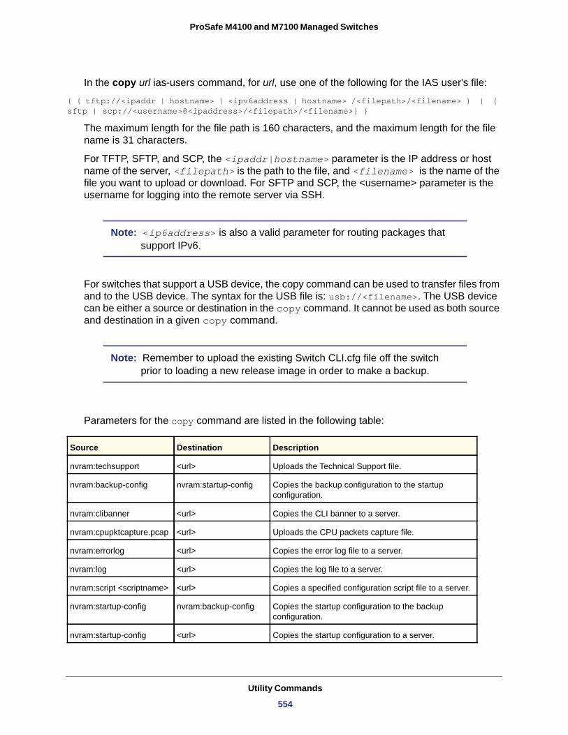
ProSafe M4100 and M7100 Managed Switches
In the copy url ias-users command, for url, use one of the following for the IAS user's file:
{ { tftp://<ipaddr | hostname> | <ipv6address | hostname> /<filepath>/<filename> } | { sftp | scp://<username>@<ipaddress>/<filepath>/<filename>} }
The maximum length for the file path is 160 characters, and the maximum length for the file name is 31 characters.
For TFTP, SFTP, and SCP, the <ipaddr|hostname> parameter is the IP address or host name of the server, <filepath> is the path to the file, and <filename> is the name of the file you want to upload or download. For SFTP and SCP, the <username> parameter is the username for logging into the remote server via SSH.
Note: <ip6address> is also a valid parameter for routing packages that support IPv6.
For switches that support a USB device, the copy command can be used to transfer files from and to the USB device. The syntax for the USB file is: usb://<filename>. The USB device can be either a source or destination in the copy command. It cannot be used as both source and destination in a given copy command.
Note: Remember to upload the existing Switch CLI.cfg file off the switch prior to loading a new release image in order to make a backup.
Parameters for the copy command are listed in the following table:
Source Destination Description
nvram:techsupport <url> Uploads the Technical Support file.
nvram:backup-config nvram:startup-config Copies the backup configuration to the startup configuration.
nvram:clibanner <url> Copies the CLI banner to a server.
nvram:cpupktcapture.pcap <url> Uploads the CPU packets capture file.
nvram:errorlog <url> Copies the error log file to a server.
nvram:log <url> Copies the log file to a server.
nvram:script <scriptname> <url> Copies a specified configuration script file to a server.
nvram:startup-config nvram:backup-config Copies the startup configuration to the backup configuration.
nvram:startup-config <url> Copies the startup configuration to a server.
Utility Commands
554
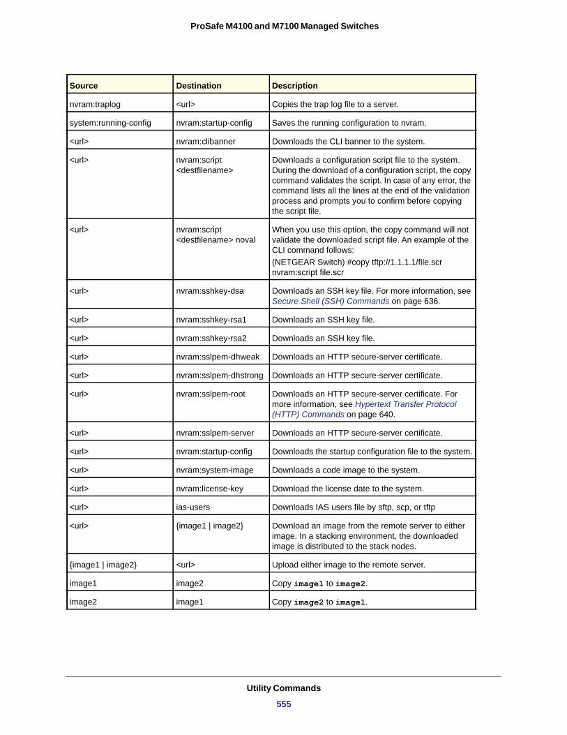
ProSafe M4100 and M7100 Managed Switches
nvram:traplog <url> Copies the trap log file to a server.
system:running-config nvram:startup-config Saves the running configuration to nvram.
<url> nvram:clibanner Downloads the CLI banner to the system.
<url> nvram:script <destfilename>
Downloads a configuration script file to the system. During the download of a configuration script, the copy command validates the script. In case of any error, the command lists all the lines at the end of the validation process and prompts you to confirm before copying the script file.
<url> nvram:script <destfilename> noval
When you use this option, the copy command will not validate the downloaded script file. An example of the CLI command follows:(NETGEAR Switch) #copy tftp://1.1.1.1/file.scr nvram:script file.scr
<url> nvram:sshkey-dsa Downloads an SSH key file. For more information, see Secure Shell (SSH) Commands on page 636.
<url> nvram:sshkey-rsa1 Downloads an SSH key file.
<url> nvram:sshkey-rsa2 Downloads an SSH key file.
<url> nvram:sslpem-dhweak Downloads an HTTP secure-server certificate.
<url> nvram:sslpem-dhstrong Downloads an HTTP secure-server certificate.
<url> nvram:sslpem-root Downloads an HTTP secure-server certificate. For more information, see Hypertext Transfer Protocol (HTTP) Commands on page 640.
<url> nvram:sslpem-server Downloads an HTTP secure-server certificate.
<url> nvram:startup-config Downloads the startup configuration file to the system.
<url> nvram:system-image Downloads a code image to the system.
<url> nvram:license-key Download the license date to the system.
<url> ias-users Downloads IAS users file by sftp, scp, or tftp
<url> {image1 | image2} Download an image from the remote server to either image. In a stacking environment, the downloaded image is distributed to the stack nodes.
{image1 | image2} <url> Upload either image to the remote server.
image1 image2 Copy image1 to image2.
image2 image1 Copy image2 to image1.
Source Destination Description
Utility Commands
555
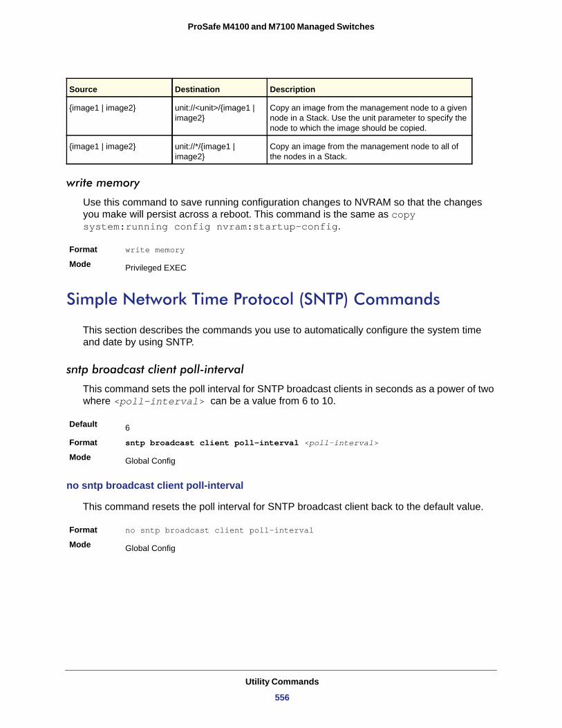
ProSafe M4100 and M7100 Managed Switches
write memory
Use this command to save running configuration changes to NVRAM so that the changes you make will persist across a reboot. This command is the same as copy system:running config nvram:startup-config.
Format write memory
Mode
Simple Network Time Protocol (SNTP) Commands
This section describes the commands you use to automatically configure the system time and date by using SNTP.
sntp broadcast client poll-interval
This command sets the poll interval for SNTP broadcast clients in seconds as a power of two where <poll-interval> can be a value from 6 to 10.
Default
Format sntp broadcast client poll-interval <poll-interval>
Mode
no sntp broadcast client poll-interval
This command resets the poll interval for SNTP broadcast client back to the default value.
Format no sntp broadcast client poll-interval
Mode
{image1 | image2} unit://<unit>/{image1 | image2}
Copy an image from the management node to a given node in a Stack. Use the unit parameter to specify the node to which the image should be copied.
{image1 | image2} unit://*/{image1 | image2}
Copy an image from the management node to all of the nodes in a Stack.
Privileged EXEC
6
Global Config
Global Config
Source Destination Description
Utility Commands
556
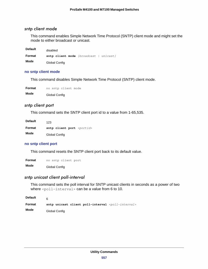
ProSafe M4100 and M7100 Managed Switches
sntp client mode
This command enables Simple Network Time Protocol (SNTP) client mode and might set the mode to either broadcast or unicast.
Default
Format sntp client mode [broadcast | unicast]
Mode
no sntp client mode
This command disables Simple Network Time Protocol (SNTP) client mode.
Format no sntp client mode
Mode
sntp client port
This command sets the SNTP client port id to a value from 1-65,535.
Default
Format sntp client port <portid>
Mode
no sntp client port
This command resets the SNTP client port back to its default value.
Format no sntp client port
Mode
sntp unicast client poll-interval
This command sets the poll interval for SNTP unicast clients in seconds as a power of two where <poll-interval> can be a value from 6 to 10.
Default
Format sntp unicast client poll-interval <poll-interval>
Mode
disabled
Global Config
Global Config
123
Global Config
Global Config
6
Global Config
Utility Commands
557
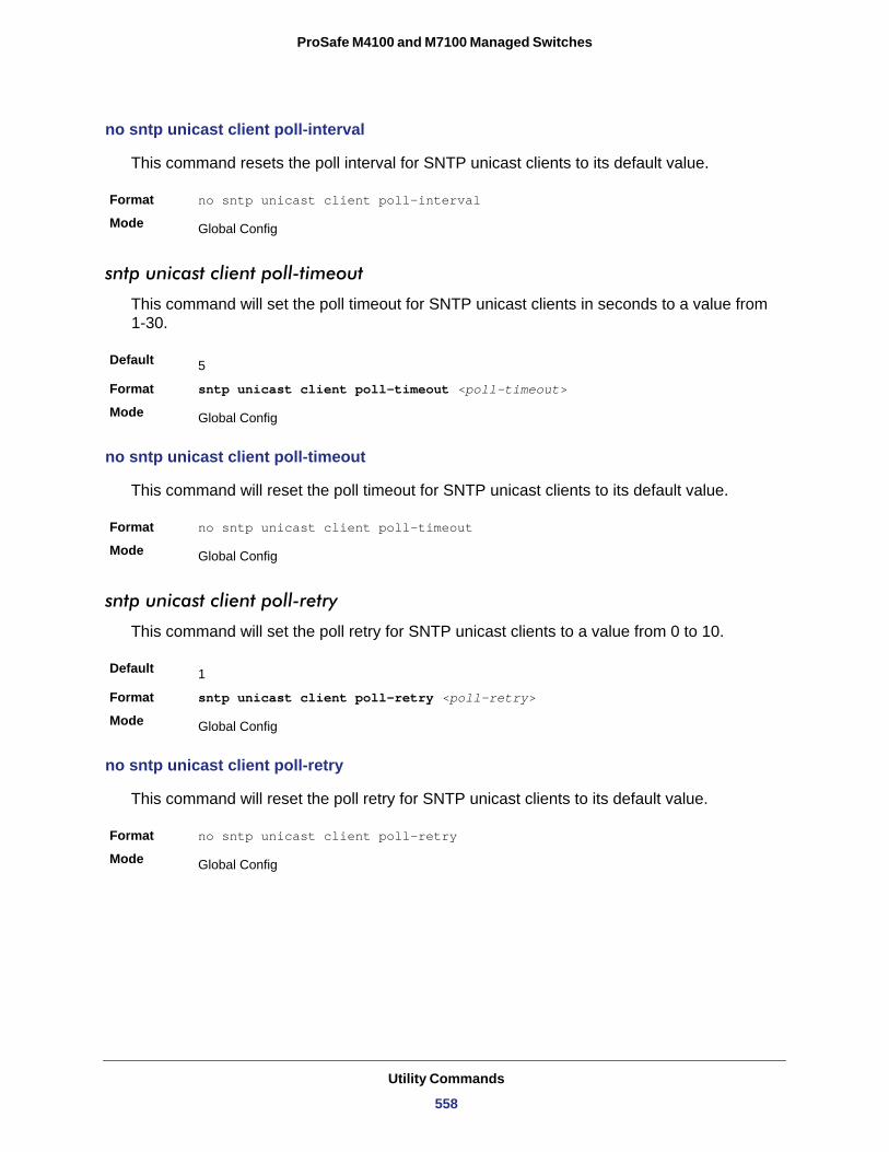
ProSafe M4100 and M7100 Managed Switches
no sntp unicast client poll-interval
This command resets the poll interval for SNTP unicast clients to its default value.
Format no sntp unicast client poll-interval
Mode
sntp unicast client poll-timeout
This command will set the poll timeout for SNTP unicast clients in seconds to a value from 1-30.
Default
Format sntp unicast client poll-timeout <poll-timeout>
Mode
no sntp unicast client poll-timeout
This command will reset the poll timeout for SNTP unicast clients to its default value.
Format no sntp unicast client poll-timeout
Mode
sntp unicast client poll-retry
This command will set the poll retry for SNTP unicast clients to a value from 0 to 10.
Default
Format sntp unicast client poll-retry <poll-retry>
Mode
no sntp unicast client poll-retry
This command will reset the poll retry for SNTP unicast clients to its default value.
Format no sntp unicast client poll-retry
Mode
Global Config
5
Global Config
Global Config
1
Global Config
Global Config
Utility Commands
558
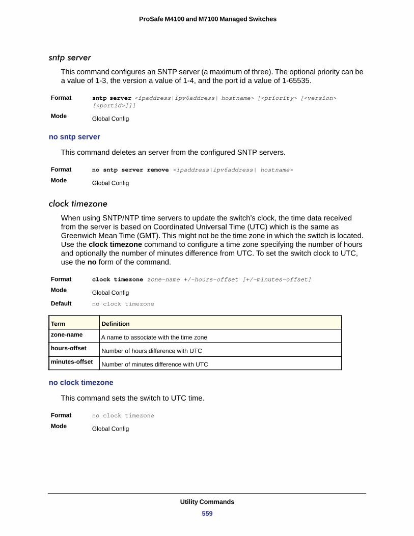
ProSafe M4100 and M7100 Managed Switches
sntp server
This command configures an SNTP server (a maximum of three). The optional priority can be a value of 1-3, the version a value of 1-4, and the port id a value of 1-65535.
Format sntp server <ipaddress|ipv6address| hostname> [<priority> [<version> [<portid>]]]
Mode
no sntp server
This command deletes an server from the configured SNTP servers.
Format no sntp server remove <ipaddress|ipv6address| hostname>
Mode
clock timezone
When using SNTP/NTP time servers to update the switch’s clock, the time data received from the server is based on Coordinated Universal Time (UTC) which is the same as Greenwich Mean Time (GMT). This might not be the time zone in which the switch is located. Use the clock timezone command to configure a time zone specifying the number of hours and optionally the number of minutes difference from UTC. To set the switch clock to UTC, use the no form of the command.
Format clock timezone zone-name +/-hours-offset [+/-minutes-offset]
Mode
Default no clock timezone
zone-name
hours-offset
minutes-offset
no clock timezone
This command sets the switch to UTC time.
Format no clock timezone
Mode
Global Config
Global Config
Global Config
Term Definition
A name to associate with the time zone
Number of hours difference with UTC
Number of minutes difference with UTC
Global Config
Utility Commands
559
ProSafe M4100 and M7100 Managed Switches
clock set
This command sets the system time and date.
Format clock set <hh:mm:ss>clock set <mm/dd/yyyy>
Mode
clock summer-time recurring
Use the clock summer-time recurring command to set the summertime offset to UTC recursively every year. If the optional parameters are not specified, they are read as either '0' or '\0', as appropriate.
Use the following parameters to configure the summer-time.
• USA—the US Daylight saving time setting is used (Start --- March, 2nd sunday 02:00 AM, End --- Nov, 1st sunday, 2:00 AM)
• EU—the European Union Daylight savings time is used (Start --- March, 5th Sunday 02:00 AM, End --- October, 5th Sunday, 3:00 AM)
• week—Week of the month. (Range: 1-5, first, last)• day—Day of the week. (Range: The first three letters by name; sun, for example.)• month—Month. (Range: The first three letters by name; jan, for example.)• hh:mm—Time in 24-hour format in hours and minutes. (Range: hh:0-23, mm: 0-59)• offset—Number of minutes to add during the summertime. (Range:1-1440)• acronym—The acronym for the time zone to be displayed when summertime is in effect.
(Range: Up to four characters)
For example:
(Switch)(Config)# clock summer-time recurring 1 sun jan00:10 2 mon mar 10:00 offset 1 zone ABC
clock summer-time date
Use the clock summer-time date command to set the summertime offset to UTC. If the optional parameters are not specified, they are read as either '0' or '\0', as appropriate.
• date—Day of the month. (Range: 1-31)• month—Month. (Range: The first three letters by name; jan, for example.)• year—Year. (Range: 2000-2097)• hh:mm—Time in 24-hour format in hours and minutes. (Range: hh: 0-23, mm: 0-59)
Global Config
Format clock summer-time recurring {USA | EU | {week day month hh:mm week day month hh:mm}} [offset offset ] [zone acronym]
Mode Global Config
Utility Commands
560
ProSafe M4100 and M7100 Managed Switches
• offset—Number of minutes to add during the summertime. (Range:1-1440)• acronym—The acronym for the time zone to be displayed when summertime is in effect.
(Range: Up to four characters)
For example:
(Switch)(config)# clock summer-time date 1 Apr 200702:00 28 Oct 2007 offset 90 zone EST
or
(Switch) (config)# clock summer-time date Apr 1 200702:00 Oct 28 2007 offset 90 zone EST
no clock summer-time
Use the no clock summer-time command to reset the summertime offset.
For example:
console(config)#no clock summer-time
show sntp
This command is used to display SNTP settings and status.
Format show sntp
Mode
Format clock summer-time date {date | month} {month | date} year hh:mm {date| month} {month | date} year hh:mm [offset offset ] [zone acronym]
Mode Global Config
Format no clock summer-time
Mode Global Config
Privileged EXEC
Term Definition
Last Update Time Time of last clock update.
Last Unicast Attempt Time Time of last transmit query (in unicast mode).
Last Attempt Status Status of the last SNTP request (in unicast mode) or unsolicited message (in broadcast
mode).
Utility Commands
561
ProSafe M4100 and M7100 Managed Switches
show sntp client
This command is used to display SNTP client settings.
Format show sntp client
Mode
Client Supported Modes
SNTP Version
Port
Client Mode
show sntp server
This command is used to display SNTP server settings and configured servers.
Format show sntp server
Mode
Server Host Address
Server Type
Server Stratum
Server Reference ID
Server Mode
Server Maximum Entries
Server Current Entries
Broadcast Count Current number of unsolicited broadcast messages that have been received and
processed by the SNTP client since last reboot.
Multicast Count Current number of unsolicited multicast messages that have been received and processed by the SNTP client since last reboot.
Privileged EXEC
Term Definition
Supported SNTP Modes (Broadcast, Unicast, or Multicast).
The highest SNTP version the client supports.
SNTP Client Port.
Configured SNTP Client Mode.
Privileged EXEC
Term Definition
IP address or hostname of configured SNTP Server.
Address Type of Server.
Claimed stratum of the server for the last received valid packet.
Reference clock identifier of the server for the last received valid packet.
SNTP Server mode.
Total number of SNTP Servers allowed.
Total number of SNTP configured.
Term Definition
Utility Commands
562
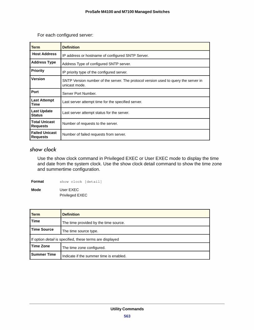
ProSafe M4100 and M7100 Managed Switches
For each configured server:
Host Address
Address Type
Priority
Version
Port
Last Attempt Time
Last Update Status
Total Unicast Requests
Failed Unicast Requests
show clock
Use the show clock command in Privileged EXEC or User EXEC mode to display the time and date from the system clock. Use the show clock detail command to show the time zone and summertime configuration.
Term Definition
IP address or hostname of configured SNTP Server.
Address Type of configured SNTP server.
IP priority type of the configured server.
SNTP Version number of the server. The protocol version used to query the server in unicast mode.
Server Port Number.
Last server attempt time for the specified server.
Last server attempt status for the server.
Number of requests to the server.
Number of failed requests from server.
Format show clock [detail]
Mode User EXEC Privileged EXEC
Term Definition
Time The time provided by the time source.
Time Source The time source type.
If option detail is specified, these terms are displayed
Time Zone The time zone configured.
Summer Time Indicate if the summer time is enabled.
Utility Commands
563
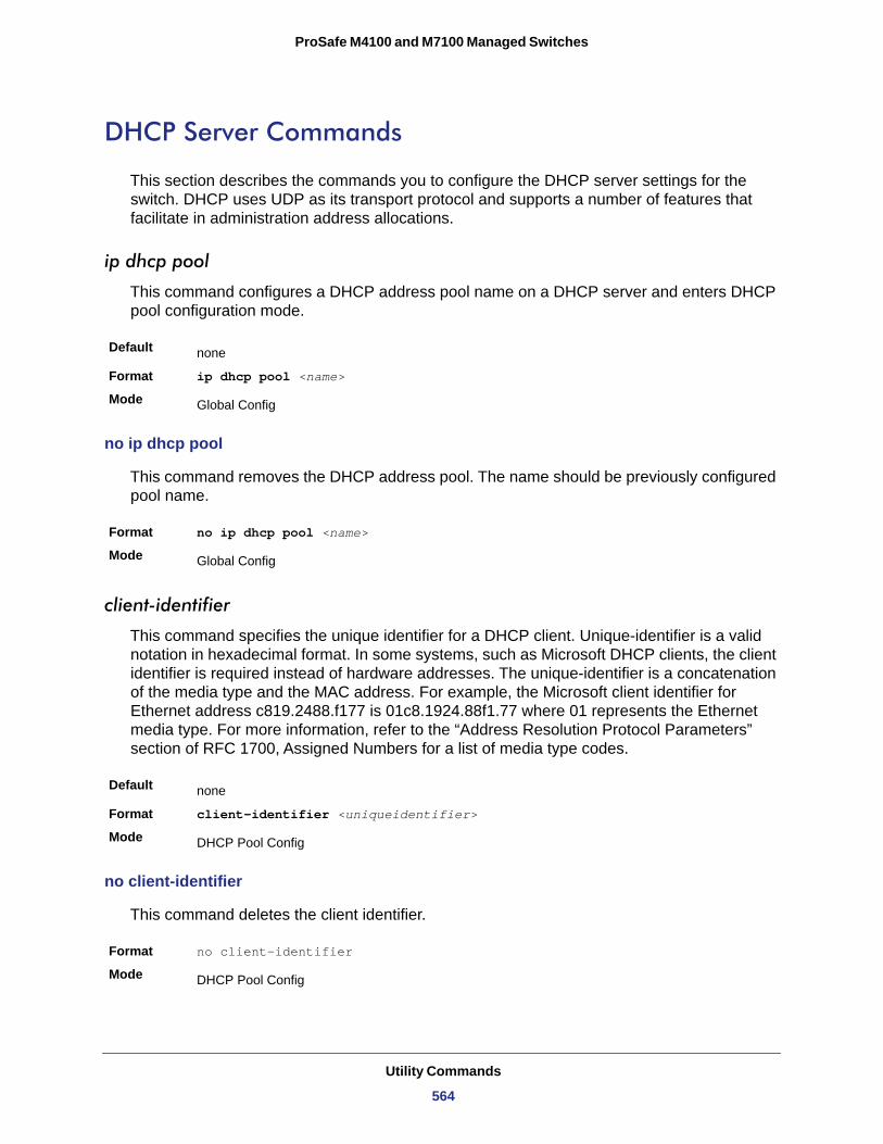
ProSafe M4100 and M7100 Managed Switches
DHCP Server Commands
This section describes the commands you to configure the DHCP server settings for the switch. DHCP uses UDP as its transport protocol and supports a number of features that facilitate in administration address allocations.
ip dhcp pool
This command configures a DHCP address pool name on a DHCP server and enters DHCP pool configuration mode.
Default
Format ip dhcp pool <name>
Mode
no ip dhcp pool
This command removes the DHCP address pool. The name should be previously configured pool name.
Format no ip dhcp pool <name>
Mode
client-identifier
This command specifies the unique identifier for a DHCP client. Unique-identifier is a valid notation in hexadecimal format. In some systems, such as Microsoft DHCP clients, the client identifier is required instead of hardware addresses. The unique-identifier is a concatenation of the media type and the MAC address. For example, the Microsoft client identifier for Ethernet address c819.2488.f177 is 01c8.1924.88f1.77 where 01 represents the Ethernet media type. For more information, refer to the “Address Resolution Protocol Parameters” section of RFC 1700, Assigned Numbers for a list of media type codes.
Default
Format client-identifier <uniqueidentifier>
Mode
no client-identifier
This command deletes the client identifier.
Format no client-identifier
Mode
none
Global Config
Global Config
none
DHCP Pool Config
DHCP Pool Config
Utility Commands
564
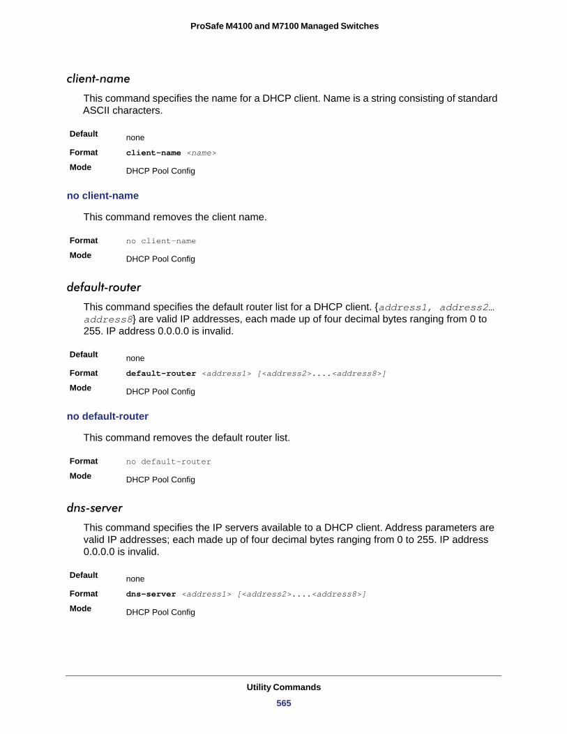
ProSafe M4100 and M7100 Managed Switches
client-name
This command specifies the name for a DHCP client. Name is a string consisting of standard ASCII characters.
Default
Format client-name <name>
Mode
no client-name
This command removes the client name.
Format no client-name
Mode
default-router
This command specifies the default router list for a DHCP client. {address1, address2… address8} are valid IP addresses, each made up of four decimal bytes ranging from 0 to 255. IP address 0.0.0.0 is invalid.
Default
Format default-router <address1> [<address2>....<address8>]
Mode
no default-router
This command removes the default router list.
Format no default-router
Mode
dns-server
This command specifies the IP servers available to a DHCP client. Address parameters are valid IP addresses; each made up of four decimal bytes ranging from 0 to 255. IP address 0.0.0.0 is invalid.
Default
Format dns-server <address1> [<address2>....<address8>]
Mode
none
DHCP Pool Config
DHCP Pool Config
none
DHCP Pool Config
DHCP Pool Config
none
DHCP Pool Config
Utility Commands
565
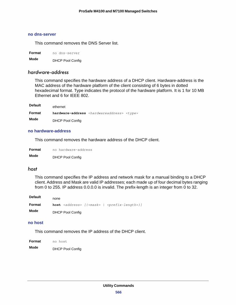
ProSafe M4100 and M7100 Managed Switches
no dns-server
This command removes the DNS Server list.
Format no dns-server
Mode
hardware-address
This command specifies the hardware address of a DHCP client. Hardware-address is the MAC address of the hardware platform of the client consisting of 6 bytes in dotted hexadecimal format. Type indicates the protocol of the hardware platform. It is 1 for 10 MB Ethernet and 6 for IEEE 802.
Default
Format hardware-address <hardwareaddress> <type>
Mode
no hardware-address
This command removes the hardware address of the DHCP client.
Format no hardware-address
Mode
host
This command specifies the IP address and network mask for a manual binding to a DHCP client. Address and Mask are valid IP addresses; each made up of four decimal bytes ranging from 0 to 255. IP address 0.0.0.0 is invalid. The prefix-length is an integer from 0 to 32.
Default
Format host <address> [{<mask> | <prefix-length>}]
Mode
no host
This command removes the IP address of the DHCP client.
Format no host
Mode
DHCP Pool Config
ethernet
DHCP Pool Config
DHCP Pool Config
none
DHCP Pool Config
DHCP Pool Config
Utility Commands
566
ProSafe M4100 and M7100 Managed Switches
lease
This command configures the duration of the lease for an IP address that is assigned from a DHCP server to a DHCP client. The overall lease time should be between 1-86400 minutes. If you specify infinite, the lease is set for 60 days. You can also specify a lease duration. Days is an integer from 0 to 59. Hours is an integer from 0 to 23. Minutes is an integer from 0 to 59.
Default
Format lease [{<days> [<hours>] [<minutes>] | infinite}]
Mode
no lease
This command restores the default value of the lease time for DHCP Server.
Format no lease
Mode
network (DHCP Pool Config)
Use this command to configure the subnet number and mask for a DHCP address pool on the server. Network-number is a valid IP address, made up of four decimal bytes ranging from 0 to 255. IP address 0.0.0.0 is invalid. Mask is the IP subnet mask for the specified address pool. The prefix-length is an integer from 0 to 32.
Default
Format network <networknumber> [{<mask> | <prefixlength>}]
Mode
no network
This command removes the subnet number and mask.
Format no network
Mode
bootfile
The command specifies the name of the default boot image for a DHCP client. The <filename> specifies the boot image file.
Format bootfile <filename>
Mode
1 (day)
DHCP Pool Config
DHCP Pool Config
none
DHCP Pool Config
DHCP Pool Config
DHCP Pool Config
Utility Commands
567
ProSafe M4100 and M7100 Managed Switches
no bootfile
This command deletes the boot image name.
Format no bootfile
Mode
domain-name
This command specifies the domain name for a DHCP client. The <domain> specifies the domain name string of the client.
Default
Format domain-name <domain>
Mode
no domain-name
This command removes the domain name.
Format no domain-name
Mode
netbios-name-server
This command configures NetBIOS Windows Internet Naming Service (WINS) name servers that are available to DHCP clients.
One IP address is required, although one can specify up to eight addresses in one command line. Servers are listed in order of preference (address1 is the most preferred server, address2 is the next most preferred server, and so on).
Default
Format netbios-name-server <address> [<address2>...<address8>]
Mode
no netbios-name-server
This command removes the NetBIOS name server list.
Format no netbios-name-server
Mode
DHCP Pool Config
none
DHCP Pool Config
DHCP Pool Config
none
DHCP Pool Config
DHCP Pool Config
Utility Commands
568
ProSafe M4100 and M7100 Managed Switches
netbios-node-type
The command configures the NetBIOS node type for Microsoft Dynamic Host Configuration Protocol (DHCP) clients. type specifies the NetBIOS node type. Valid types are:
• b-node—Broadcast• p-node—Peer-to-peer• m-node—Mixed• h-node—Hybrid (recommended)
Default
Format netbios-node-type <type>
Mode
no netbios-node-type
This command removes the NetBIOS node Type.
Format no netbios-node-type
Mode
next-server
This command configures the next server in the boot process of a DHCP client.The <address> parameter is the IP address of the next server in the boot process, which is typically a TFTP server.
Default
Format next-server <address>
Mode
no next-server
This command removes the boot server list.
Format no next-server
Mode
option
The option command configures DHCP Server options. The <code> parameter specifies the DHCP option code and ranges from 1-254. The <ascii string> parameter specifies an NVT ASCII character string. ASCII character strings that contain white space must be delimited by quotation marks. The hex <string> parameter specifies hexadecimal data. In hexadecimal, character strings are two hexadecimal digits. You can separate each byte by a
none
DHCP Pool Config
DHCP Pool Config
inbound interface helper addresses
DHCP Pool Config
DHCP Pool Config
Utility Commands
569
ProSafe M4100 and M7100 Managed Switches
period (for example, a3.4f.22.0c), colon (for example, a3:4f:22:0c), or white space (for example, a3 4f 22 0c).
Default
Format option <code> {ascii string | hex <string1> [<string2>...<string8>] | ip <address1> [<address2>...<address8>]}
Mode
no option
This command removes the DHCP Server options. The <code> parameter specifies the DHCP option code.
Format no option <code>
Mode
ip dhcp excluded-address
This command specifies the IP addresses that a DHCP server should not assign to DHCP clients. Low-address and high-address are valid IP addresses; each made up of four decimal bytes ranging from 0 to 255. IP address 0.0.0.0 is invalid.
Default
Format ip dhcp excluded-address <lowaddress> [highaddress]
Mode
no ip dhcp excluded-address
This command removes the excluded IP addresses for a DHCP client. Low-address and high-address are valid IP addresses; each made up of four decimal bytes ranging from 0 to 255. IP address 0.0.0.0 is invalid.
Format no ip dhcp excluded-address <lowaddress> [highaddress]
Mode
ip dhcp ping packets
Use this command to specify the number, in a range from 2-10, of packets a DHCP server sends to a pool address as part of a ping operation. By default the number of packets sent to a pool address is 2, which is the smallest allowed number when sending packets. Setting the number of packets to 0 disables this command.
none
DHCP Pool Config
DHCP Pool Config
none
Global Config
Global Config
Default 2
Utility Commands
570
ProSafe M4100 and M7100 Managed Switches
no ip dhcp ping packets
This command prevents the server from pinging pool addresses and sets the number of packets to 0.
Default
Format no ip dhcp ping packets
Mode
service dhcp
This command enables the DHCP server.
Default
Format service dhcp
Mode
no service dhcp
This command disables the DHCP server.
Format no service dhcp
Mode
ip dhcp bootp automatic
This command enables the allocation of the addresses to the bootp client. The addresses are from the automatic address pool.
Default
Format ip dhcp bootp automatic
Mode
no ip dhcp bootp automatic
This command disables the allocation of the addresses to the bootp client. The address are from the automatic address pool.
Format no ip dhcp bootp automatic
Mode
Format ip dhcp ping packets <0,2-10>
Mode Global Config
0
Global Config
disabled
Global Config
Global Config
disabled
Global Config
Global Config
Utility Commands
571
ProSafe M4100 and M7100 Managed Switches
ip dhcp conflict logging
This command enables conflict logging on DHCP server.
Default
Format ip dhcp conflict logging
Mode
no ip dhcp conflict logging
This command disables conflict logging on DHCP server.
Format no ip dhcp conflict logging
Mode
clear ip dhcp binding
This command deletes an automatic address binding from the DHCP server database. If “*” is specified, the bindings corresponding to all the addresses are deleted. <address> is a valid IP address made up of four decimal bytes ranging from 0 to 255. IP address 0.0.0.0 is invalid.
Format clear ip dhcp binding {<address> | *}
Mode
clear ip dhcp server statistics
This command clears DHCP server statistics counters.
Format clear ip dhcp server statistics
Mode
clear ip dhcp conflict
The command is used to clear an address conflict from the DHCP Server database. The server detects conflicts using a ping. DHCP server clears all conflicts If the asterisk (*) character is used as the address parameter.
Default
Format clear ip dhcp conflict {<address> | *}
Mode
enabled
Global Config
Global Config
Privileged EXEC
Privileged EXEC
none
Privileged EXEC
Utility Commands
572
ProSafe M4100 and M7100 Managed Switches
show ip dhcp binding
This command displays address bindings for the specific IP address on the DHCP server. If no IP address is specified, the bindings corresponding to all the addresses are displayed.
Format show ip dhcp binding [<address>]
Modes • Privileged EXEC• User EXEC
IP address
Hardware Address
Lease expiration
Type
show ip dhcp global configuration
This command displays address bindings for the specific IP address on the DHCP server. If no IP address is specified, the bindings corresponding to all the addresses are displayed.
Format show ip dhcp global configuration
Modes • Privileged EXEC• User EXEC
Service DHCP
Number of Ping Packets
Conflict Logging
BootP Automatic
show ip dhcp pool configuration
This command displays pool configuration. If all is specified, configuration for all the pools is displayed.
Format show ip dhcp pool configuration {<name> | all}
Modes • Privileged EXEC• User EXEC
Term Definition
The IP address of the client.
The MAC Address or the client identifier.
The lease expiration time of the IP address assigned to the client.
The manner in which IP address was assigned to the client.
Term Definition
The field to display the status of dhcp protocol.
The maximum number of Ping Packets that will be sent to verify that an ip address id not already assigned.
Shows whether conflict logging is enabled or disabled.
Shows whether BootP for dynamic pools is enabled or disabled.
Utility Commands
573
ProSafe M4100 and M7100 Managed Switches
Pool Name
Pool Type
Lease Time
DNS Servers
Default Routers
The following additional field is displayed for Dynamic pool type:
Network
The following additional fields are displayed for Manual pool type:
Client Name
Client Identifier
Hardware Address
Hardware Address Type
Host
show ip dhcp server statistics
This command displays DHCP server statistics.
Format show ip dhcp server statistics
Modes • Privileged EXEC• User EXEC
Automatic Bindings
Expired Bindings
Malformed Bindings
Field Definition
The name of the configured pool.
The pool type.
The lease expiration time of the IP address assigned to the client.
The list of DNS servers available to the DHCP client .
The list of the default routers available to the DHCP client
Field Definition
The network number and the mask for the DHCP address pool.
Field Definition
The name of a DHCP client.
The unique identifier of a DHCP client.
The hardware address of a DHCP client.
The protocol of the hardware platform.
The IP address and the mask for a manual binding to a DHCP client.
Field Definition
The number of IP addresses that have been automatically mapped to the MAC addresses of hosts that are found in the DHCP database.
The number of expired leases.
The number of truncated or corrupted messages that were received by the DHCP server.
Utility Commands
574
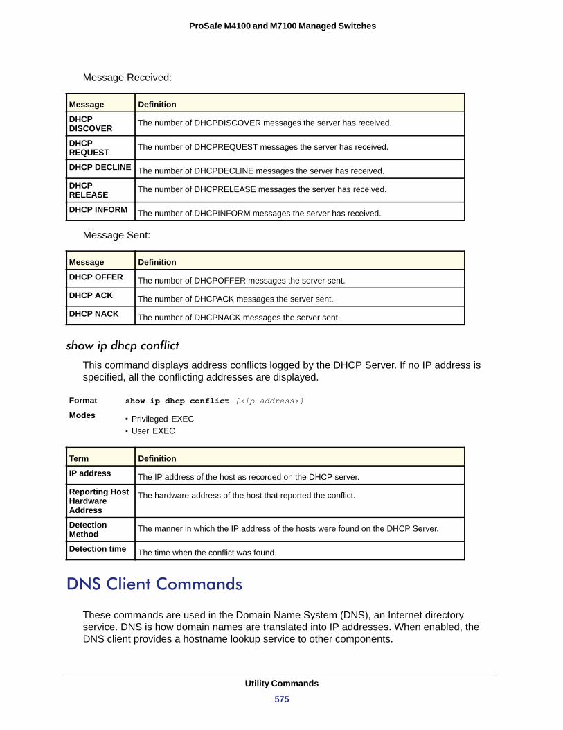
ProSafe M4100 and M7100 Managed Switches
Message Received:
DHCP DISCOVER
DHCP REQUEST
DHCP DECLINE
DHCP RELEASE
DHCP INFORM
Message Sent:
DHCP OFFER
DHCP ACK
DHCP NACK
show ip dhcp conflict
This command displays address conflicts logged by the DHCP Server. If no IP address is specified, all the conflicting addresses are displayed.
Format show ip dhcp conflict [<ip-address>]
Modes • Privileged EXEC• User EXEC
IP address
Reporting Host Hardware Address
Detection Method
Detection time
DNS Client Commands
These commands are used in the Domain Name System (DNS), an Internet directory service. DNS is how domain names are translated into IP addresses. When enabled, the DNS client provides a hostname lookup service to other components.
Message Definition
The number of DHCPDISCOVER messages the server has received.
The number of DHCPREQUEST messages the server has received.
The number of DHCPDECLINE messages the server has received.
The number of DHCPRELEASE messages the server has received.
The number of DHCPINFORM messages the server has received.
Message Definition
The number of DHCPOFFER messages the server sent.
The number of DHCPACK messages the server sent.
The number of DHCPNACK messages the server sent.
Term Definition
The IP address of the host as recorded on the DHCP server.
The hardware address of the host that reported the conflict.
The manner in which the IP address of the hosts were found on the DHCP Server.
The time when the conflict was found.
Utility Commands
575
ProSafe M4100 and M7100 Managed Switches
ip domain lookup
Use this command to enable the DNS client.
Default
Format ip domain lookup
Mode
no ip domain lookup
Use this command to disable the DNS client.
Format no ip domain lookup
Mode
ip domain name
Use this command to define a default domain name that the software uses to complete unqualified host names (names with a domain name). By default, no default domain name is configured in the system. <name> may not be longer than 255 characters and should not include an initial period. This <name> should be used only when the default domain name list, configured using the ip domain list command, is empty.
Default
Format ip domain name <name>
Mode
Example: The CLI command ip domain name yahoo.com will configure yahoo.com as a default domain name. For an unqualified hostname xxx, a DNS query is made to find the IP address corresponding to xxx.yahoo.com.
no ip domain name
Use this command to remove the default domain name configured using the ip domain name command.
Format no ip domain name
Mode
ip domain list
Use this command to define a list of default domain names to complete unqualified names. By default, the list is empty. Each name must be no more than 256 characters, and should not include an initial period. The default domain name, configured using the ip domain
enabled
Global Config
Global Config
none
Global Config
Global Config
Utility Commands
576
ProSafe M4100 and M7100 Managed Switches
name command, is used only when the default domain name list is empty. A maximum of 32 names can be entered in to this list.
Default
Format ip domain list <name>
Mode
no ip domain list
Use this command to delete a name from a list.
Format no ip domain list <name>
Mode
ip name server
Use this command to configure the available name servers. Up to eight servers can be defined in one command or by using multiple commands. The parameter <server-address> is a valid IPv4 or IPv6 address of the server. The preference of the servers is determined by the order they were entered.
Format ip name-server <server-address1> [server-address2...server-address8]
Mode
no ip name server
Use this command to remove a name server.
Format no ip name-server [server-address1...server-address8]
Mode
ip host
Use this command to define static host name-to-address mapping in the host cache. <name> is host name. <ip address> is the IP address of the host.
Default
Format ip host <name> <ipaddress>
Mode
none
Global Config
Global Config
Global Config
Global Config
none
Global Config
Utility Commands
577
ProSafe M4100 and M7100 Managed Switches
no ip host
Use this command to remove the name-to-address mapping.
Format no ip host <name>
Mode
ipv6 host
Use this command to define static host name-to-IPv6 address mapping in the host cache. <name> is host name. <v6 address> is the IPv6 address of the host.
Default
Format ipv6 host <name> <v6 address>
Mode
no ipv6 host
Use this command to remove the static host name-to-IPv6 address mapping in the host cache.
Format no ipv6 host <name>
Mode
ip domain retry
Use this command to specify the number of times to retry sending Domain Name System (DNS) queries. The parameter <number> indicates the number of times to retry sending a DNS query to the DNS server. This number ranges from 0 to 100.
Default
Format ip domain retry <number>
Mode
no ip domain retry
Use this command to return to the default.
Format no ip domain retry <number>
Mode
Global Config
none
Global Config
Global Config
2
Global Config
Global Config
Utility Commands
578
ProSafe M4100 and M7100 Managed Switches
ip domain timeout
Use this command to specify the amount of time to wait for a response to a DNS query. The parameter <seconds> specifies the time, in seconds, to wait for a response to a DNS query. <seconds> ranges from 0 to 3600.
Default
Format ip domain timeout <seconds>
Mode
no ip domain timeout
Use this command to return to the default setting.
Format no ip domain timeout <seconds>
Mode
clear host
Use this command to delete entries from the host name-to-address cache. This command clears the entries from the DNS cache maintained by the software. This command clears both IPv4 and IPv6 entries.
Format clear host {<name> | all}
Mode
name
all
show hosts
Use this command to display the default domain name, a list of name server hosts, the static and the cached list of host names and addresses <name> ranges from 1-255 characters. This command displays both IPv4 and IPv6 entries.
Format show hosts [name]
Mode
3
Global Config
Global Config
Privileged EXEC
Field Description
A particular host entry to remove. <name> ranges from 1-255 characters.
Removes all entries.
User EXEC
Field Description
Host Name Domain host name.
Default Domain Default domain name.
Utility Commands
579
ProSafe M4100 and M7100 Managed Switches
Example: The following shows example CLI display output for the command.
<Switch> show hosts
Host name......................... DeviceDefault domain.................... gm.comDefault domain list............... yahoo.com, Stanford.edu, rediff.com Domain Name lookup................ EnabledNumber of retries................. 5Retry timeout period.............. 1500Name servers (Preference order)... 176.16.1.18 176.16.1.19
Configured host name-to-address mapping:
Host Addresses------------------------------ ------------------------------accounting.gm.com 176.16.8.8
Host Total Elapsed Type Addresses--------------- -------- ------ -------- --------------www.stanford.edu 72 3 IP 171.64.14.203
Packet Capture Commands
Packet capture commands assist in troubleshooting protocol-related problems with the management CPU. The packets to and from the management CPU can be captured in an internally allocated buffer area for export to a PC host for protocol analysis. Public domain packet analysis tools like Ethereal can be used to decode and review the packets in detail. Capturing can be performed in a variety of modes, either transmit-side only, receive-side only, or both. The number of packets captured will depend on the size of the captured packets.
capture {start|stop}
Use the command capture start to manually start capturing CPU packets for packet trace. Capturing packets is stopped automatically when 128 packets are captured and have not yet been displayed during a capture session. It is guaranteed that packets not displayed and not saved will not be lost when capturing is in progress. Use the command capture stop to manually stop capturing CPU packets for packet trace before the moment when 128
Default Domain List Default domain list.
Domain Name Lookup DNS client enabled/disabled.
Number of Retries Number of time to retry sending Domain Name System (DNS) queries.
Retry Timeout Period Amount of time to wait for a response to a DNS query.
Name Servers Configured name servers.
Field Description
Utility Commands
580
ProSafe M4100 and M7100 Managed Switches
packets are captured and capturing packets is stopped automatically.The packet capture operates in three modes:
• Capture file • Remote capture • Capture line
The command is not persistent across a reboot cycle.
Format capture {start|stop} {transmit|receive|all}
Mode
capture {file|remote|line}
Use this command to configure file capture options. The command is persistent across a reboot cycle.
Default
Format capture {file|remote|line}
Mode
file
remote
line
Privileged EXEC
Remote
Global Config
Parameter Description
In capture file mode, the captured packets are stored in a file on NVRAM. The maximum file size defaults to 524,288 bytes. The switch can transfer the file to a TFTP server via TFTP, SFTP, SCP via CLI, web and SNMP. The file is formatted in pcap format, is named cpuPktCapture.pcap, and can be examined using network analyzer tools such as Wireshark® by Ethereal®. Starting a file capture automatically terminates any remote capture sessions and line capturing. After the packet capture is activated, the capture proceeds until the capture file reaches its maximum size, or until the capture is stopped manually using the CLI command capture stop.
In remote capture mode, the captured packets are redirected in real time to an external computer running the Wireshark tool for Microsoft® Windows®. A packet capture server runs on the switch side and sends the captured packets via a TCP connection to the Wireshark tool. The remote capture can be enabled or disabled using the CLI. There should be a Windows computer with the Wireshark tool to display the captured file. When using the remote capture mode, the switch does not store any captured data locally on its file system. You can configure the IP port number for connecting Wireshark to the switch. The default port number is 2002. If a firewall is installed between the Wireshark PC and the switch, these ports must be allowed to pass through the firewall. You must configure the firewall to allow the Wireshark computer to initiate TCP connections to the switch. If the socket connection to Wireshark has been established, the captured CPU packets are written to the data socket. Wireshark receives the packets and processes it to display. This continues until the session is terminated by either end. Starting a remote capture session automatically terminates the file capture and line capturing.
In capture line mode, the captured packets are saved in real-time mode into the RAM and can be displayed on the CLI. Starting a line capture automatically terminates any remote capture session and capturing into a file.
Utility Commands
581
ProSafe M4100 and M7100 Managed Switches
no capture
Use this command to reset the capture mode to remote mode.
Format no capture
Mode
capture remote port
Use this command to configure file capture options. The command is persistent across a reboot cycle.
Default
Format capture remote port <port-id>
Mode
no capture remote port
Use this command to reset the remote port to the default (2002).
Format no capture report port
Mode
capture file size
Use this command to configure file capture options. The command is persistent across a reboot cycle. The range is from 2 to 512 Kbytes.
Default
Format capture file size <file-size>
Mode
no capture file size
Use this command to reset the file size to the default (512Kbytes).
Format no capture file size
Mode
capture line wrap
There are two methods to configure capturing CPU packets into RAM: capture line wrap and no capture line wrap. Use the capture line wrap command to stop automatically capturing packets when 128 packets are saved and have not yet been
Global Config
2002
Global Config
Global Config
512Kbytes
Global Config
Global Config
Utility Commands
582
ProSafe M4100 and M7100 Managed Switches
displayed during the capturing session. When capturing is in progress, unsaved, not-yet-displayed packets will not be lost.
Default
Format capture line wrap
Mode
no capture line wrap
Use this command to disable the capture line wrap mode.
Format no capture line wrap
Mode
show capture packets
Use this command to display packets captured and saved to RAM. It is possible to capture and save into RAM, packets that are received or transmitted through the CPU. A maximum 128 packets can be saved into RAM per capturing session. A maximum 128 bytes per packet can be saved into the RAM. If a packet holds more than 128 bytes, only the first 128 bytes are saved; data more than 128 bytes is skipped and cannot be displayed in the CLI.
Capturing packets is stopped automatically when 128 packets are captured and have not yet been displayed during a capture session. Captured packets are not retained after a reload cycle.
Format show capture packets
Mode
Serviceability Packet Tracing Commands
These commands improve the capability of network engineers to diagnose conditions affecting their managed switch product.
CAUTION:
The output of the debug commands can be long and might adversely affect system performance.
debug arp
Use this command to enable ARP debug protocol messages.
Disabled
Global Config
Global Config
Privileged EXEC
Default disabled
Utility Commands
583
ProSafe M4100 and M7100 Managed Switches
no debug arp
Use this command to disable ARP debug protocol messages.
Format no debug arp
Mode
debug auto-voip
Use this command to enable Auto VOIP debug messages. Use the optional parameters to trace H323, SCCP, or SIP packets respectively.
Default
Format debug auto-voip [H323|SCCP|SIP]
Mode
no debug auto-voip
Use this command to disable Auto VOIP debug messages.
Format no debug auto-voip
Mode
debug clear
This command disables all previously enabled “debug” traces.
Default
Format debug clear
Mode
debug console
This command enables the display of “debug” trace output on the login session in which it is executed. Debug console display must be enabled in order to view any trace output. The output of debug trace commands will appear on all login sessions for which debug console has been enabled. The configuration of this command remains in effect for the life of the login session. The effect of this command is not persistent across resets.
Format debug arp
Mode Privileged EXEC
Privileged EXEC
disabled
Privileged EXEC
Privileged EXEC
disabled
Privileged EXEC
Default disabled
Utility Commands
584
ProSafe M4100 and M7100 Managed Switches
no debug console
This command disables the display of “debug” trace output on the login session in which it is executed.
Format no debug console
Mode
debug crashlog
Use this command to view information contained in the crash log file that the system maintains when it experiences an unexpected reset. The crash log file contains the following information:
• Call stack information in both primitive and verbose forms• Log Status• Buffered logging• Event logging• Persistent logging• System Information (output of sysapiMbufDump)• Message Queue Debug Information• Memory Debug Information• Memory Debug Status• OS Information (output of osapiShowTasks)• /proc information (meminfo, cpuinfo, interrupts, version and net/sockstat)
Format debug crashlog {[kernel] crashlog-number [upload url] | proc | verbose | deteall}
Mode
Default
Format debug console
Mode Privileged EXEC
Privileged EXEC
Privileged EXEC
Disabled
Parameter Definition
kernel View the crash log file for the kernel. crashlog-number Specifies the file number to view. The system maintains up to four copies, and the valid
range is 1–4.
upload url To upload the crash log to a TFTP server, use the upload keyword and specify the required TFTP server information.
Utility Commands
585
ProSafe M4100 and M7100 Managed Switches
debug dhcp packet
Use this command to display “debug” information about DHCPv4 client activities and trace DHCPv4 packets to and from the local DHCPv4 client.
Default
Format debug dhcp packet [transmit | receive]
Mode
no debug dhcp
Use this command to disable the display of “debug” trace output for DHCPv4 client activity.
Format no debug dhcp packet [transmit | receive]
Mode
debug dot1x packet
Use this command to enable dot1x packet debug trace.
Default
Format debug dot1x
Mode
no debug dot1x packet
Use this command to disable dot1x packet debug trace.
Format no debug dot1x
Mode
debug igmpsnooping packet
This command enables tracing of IGMP Snooping packets received and transmitted by the switch.
proc View the application process crashlog.
verbose Enable the verbose crashlog
deleteall Delete all crash log files on the system.
disabled
Privileged EXEC
Privileged EXEC
disabled
Privileged EXEC
Privileged EXEC
Default disabled
Parameter Definition
Utility Commands
586
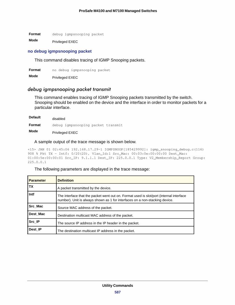
ProSafe M4100 and M7100 Managed Switches
no debug igmpsnooping packet
This command disables tracing of IGMP Snooping packets.
Format no debug igmpsnooping packet
Mode
debug igmpsnooping packet transmit
This command enables tracing of IGMP Snooping packets transmitted by the switch. Snooping should be enabled on the device and the interface in order to monitor packets for a particular interface.
Default
Format debug igmpsnooping packet transmit
Mode
A sample output of the trace message is shown below.
<15> JAN 01 02:45:06 192.168.17.29-1 IGMPSNOOP[185429992]: igmp_snooping_debug.c(116) 908 % Pkt TX - Intf: 0/20(20), Vlan_Id:1 Src_Mac: 00:03:0e:00:00:00 Dest_Mac: 01:00:5e:00:00:01 Src_IP: 9.1.1.1 Dest_IP: 225.0.0.1 Type: V2_Membership_Report Group: 225.0.0.1
The following parameters are displayed in the trace message:
Format debug igmpsnooping packet
Mode Privileged EXEC
Privileged EXEC
disabled
Privileged EXEC
Parameter Definition
TX A packet transmitted by the device.
Intf The interface that the packet went out on. Format used is slot/port (internal interface number). Unit is always shown as 1 for interfaces on a non-stacking device.
Src_Mac Source MAC address of the packet.
Dest_Mac Destination multicast MAC address of the packet.
Src_IP The source IP address in the IP header in the packet.
Dest_IP The destination multicast IP address in the packet.
Utility Commands
587
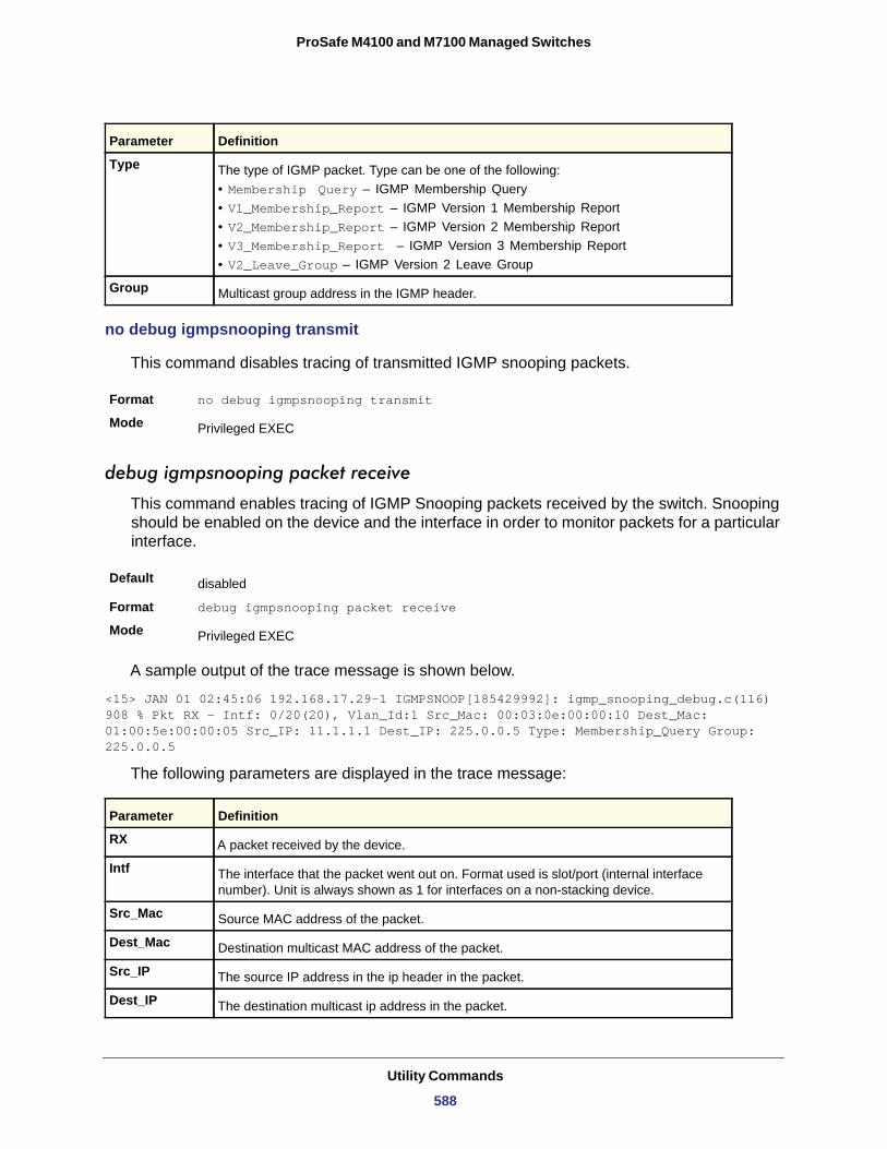
ProSafe M4100 and M7100 Managed Switches
no debug igmpsnooping transmit
This command disables tracing of transmitted IGMP snooping packets.
Format no debug igmpsnooping transmit
Mode
debug igmpsnooping packet receive
This command enables tracing of IGMP Snooping packets received by the switch. Snooping should be enabled on the device and the interface in order to monitor packets for a particular interface.
Default
Format debug igmpsnooping packet receive
Mode
A sample output of the trace message is shown below.
<15> JAN 01 02:45:06 192.168.17.29-1 IGMPSNOOP[185429992]: igmp_snooping_debug.c(116) 908 % Pkt RX - Intf: 0/20(20), Vlan_Id:1 Src_Mac: 00:03:0e:00:00:10 Dest_Mac: 01:00:5e:00:00:05 Src_IP: 11.1.1.1 Dest_IP: 225.0.0.5 Type: Membership_Query Group: 225.0.0.5
The following parameters are displayed in the trace message:
Type The type of IGMP packet. Type can be one of the following:• Membership Query – IGMP Membership Query• V1_Membership_Report – IGMP Version 1 Membership Report• V2_Membership_Report – IGMP Version 2 Membership Report• V3_Membership_Report – IGMP Version 3 Membership Report• V2_Leave_Group – IGMP Version 2 Leave Group
Group Multicast group address in the IGMP header.
Privileged EXEC
disabled
Privileged EXEC
Parameter Definition
RX A packet received by the device.
Intf The interface that the packet went out on. Format used is slot/port (internal interface number). Unit is always shown as 1 for interfaces on a non-stacking device.
Src_Mac Source MAC address of the packet.
Dest_Mac Destination multicast MAC address of the packet.
Src_IP The source IP address in the ip header in the packet.
Dest_IP The destination multicast ip address in the packet.
Parameter Definition
Utility Commands
588
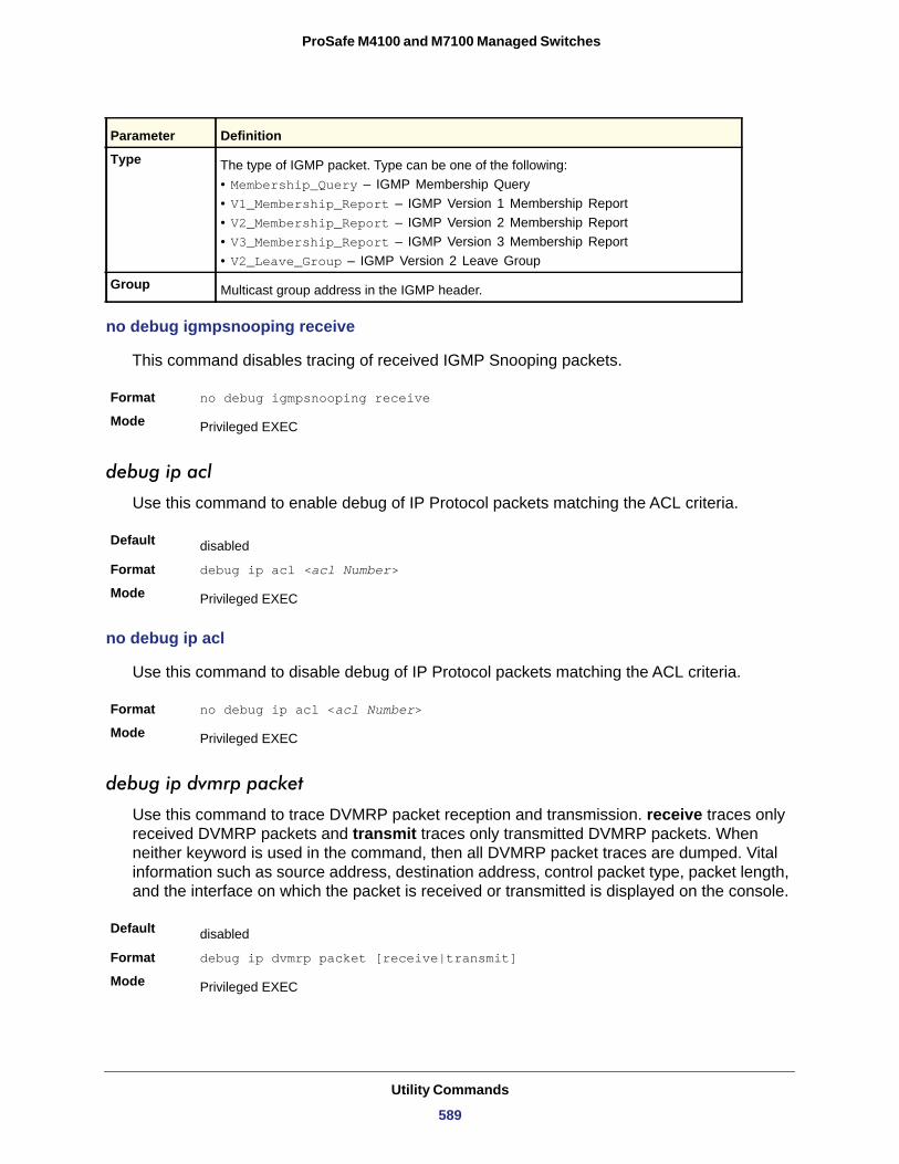
ProSafe M4100 and M7100 Managed Switches
no debug igmpsnooping receive
This command disables tracing of received IGMP Snooping packets.
Format no debug igmpsnooping receive
Mode
debug ip acl
Use this command to enable debug of IP Protocol packets matching the ACL criteria.
Default
Format debug ip acl <acl Number>
Mode
no debug ip acl
Use this command to disable debug of IP Protocol packets matching the ACL criteria.
Format no debug ip acl <acl Number>
Mode
debug ip dvmrp packet
Use this command to trace DVMRP packet reception and transmission. receive traces only received DVMRP packets and transmit traces only transmitted DVMRP packets. When neither keyword is used in the command, then all DVMRP packet traces are dumped. Vital information such as source address, destination address, control packet type, packet length, and the interface on which the packet is received or transmitted is displayed on the console.
Default
Format debug ip dvmrp packet [receive|transmit]
Mode
Type The type of IGMP packet. Type can be one of the following:• Membership_Query – IGMP Membership Query• V1_Membership_Report – IGMP Version 1 Membership Report• V2_Membership_Report – IGMP Version 2 Membership Report• V3_Membership_Report – IGMP Version 3 Membership Report• V2_Leave_Group – IGMP Version 2 Leave Group
Group Multicast group address in the IGMP header.
Privileged EXEC
disabled
Privileged EXEC
Privileged EXEC
disabled
Privileged EXEC
Parameter Definition
Utility Commands
589
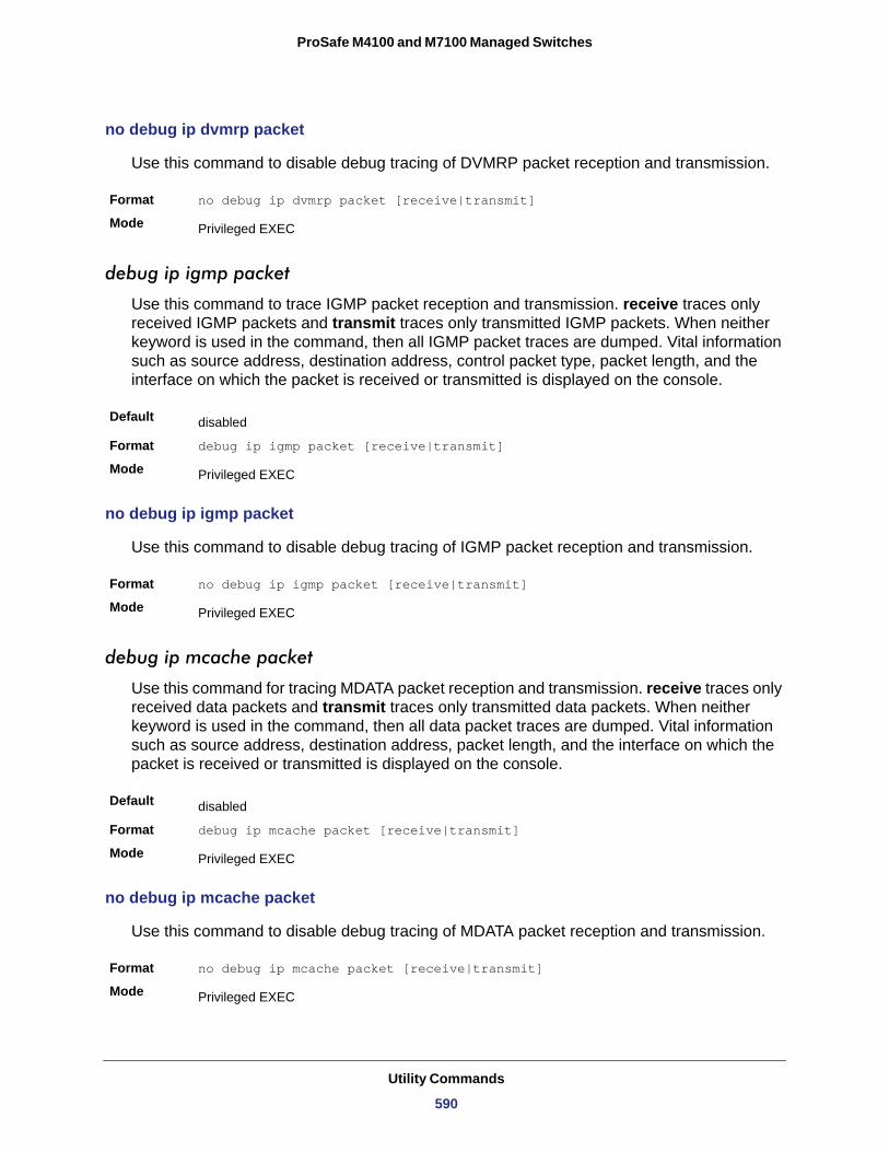
ProSafe M4100 and M7100 Managed Switches
no debug ip dvmrp packet
Use this command to disable debug tracing of DVMRP packet reception and transmission.
Format no debug ip dvmrp packet [receive|transmit]
Mode
debug ip igmp packet
Use this command to trace IGMP packet reception and transmission. receive traces only received IGMP packets and transmit traces only transmitted IGMP packets. When neither keyword is used in the command, then all IGMP packet traces are dumped. Vital information such as source address, destination address, control packet type, packet length, and the interface on which the packet is received or transmitted is displayed on the console.
Default
Format debug ip igmp packet [receive|transmit]
Mode
no debug ip igmp packet
Use this command to disable debug tracing of IGMP packet reception and transmission.
Format no debug ip igmp packet [receive|transmit]
Mode
debug ip mcache packet
Use this command for tracing MDATA packet reception and transmission. receive traces only received data packets and transmit traces only transmitted data packets. When neither keyword is used in the command, then all data packet traces are dumped. Vital information such as source address, destination address, packet length, and the interface on which the packet is received or transmitted is displayed on the console.
Default
Format debug ip mcache packet [receive|transmit]
Mode
no debug ip mcache packet
Use this command to disable debug tracing of MDATA packet reception and transmission.
Format no debug ip mcache packet [receive|transmit]
Mode
Privileged EXEC
disabled
Privileged EXEC
Privileged EXEC
disabled
Privileged EXEC
Privileged EXEC
Utility Commands
590
ProSafe M4100 and M7100 Managed Switches
debug ip pimdm packet
Use this command to trace PIMDM packet reception and transmission. receive traces only received PIMDM packets and transmit traces only transmitted PIMDM packets. When neither keyword is used in the command, then all PIMDM packet traces are dumped. Vital information such as source address, destination address, control packet type, packet length, and the interface on which the packet is received or transmitted is displayed on the console.
Default
Format debug ip pimdm packet [receive|transmit]
Mode
no debug ip pimdm packet
Use this command to disable debug tracing of PIMDM packet reception and transmission.
debug ip pimsm packet
Use this command to trace PIMSM packet reception and transmission. receive traces only received PIMSM packets and transmit traces only transmitted PIMSM packets. When neither keyword is used in the command, then all PIMSM packet traces are dumped. Vital information such as source address, destination address, control packet type, packet length, and the interface on which the packet is received or transmitted is displayed on the console.
Default
Format debug ip pimsm packet [receive|transmit]
Mode
no debug ip pimsm packet
Use this command to disable debug tracing of PIMSM packet reception and transmission.
Format no debug ip pimsm packet [receive|transmit]
Mode
debug ip vrrp
Use this command to enable VRRP debug protocol messages.
Default
Format debug ip vrrp
Mode
disabled
Privileged EXEC
Format no debug ip pimdm packet [receive|transmit]
Mode Privileged EXEC
disabled
Privileged EXEC
Privileged EXEC
disabled
Privileged EXEC
Utility Commands
591
ProSafe M4100 and M7100 Managed Switches
no debug ip vrrp
Use this command to disable VRRP debug protocol messages.
Format no debug ip vrrp
Mode
debug ipv6 dhcp
Use this command to display “debug” information about DHCPv6 client activities and trace DHCPv6 packets to and from the local DHCPv6 client.
Default
Format debug ipv6 dhcp
Mode
no ipv6 debug dhcp
Use this command to disable the display of “debug” trace output for DHCPv6 client activity.
Format no debug ipv6 dhcp
Mode
debug ipv6 mcache packet
Use this command for tracing MDATAv6 packet reception and transmission. receive traces only received data packets and transmit traces only transmitted data packets. When neither keyword is used in the command, then all data packet traces are dumped. Vital information such as source address, destination address, packet length, and the interface on which the packet is received or transmitted is displayed on the console.
Default
Format debug ipv6 mcache packet [receive|transmit]
Mode
no debug ipv6 mcache packet
Use this command to disable debug tracing of MDATAv6 packet reception and transmission.
Format no debug ipv6 mcache packet [receive|transmit]
Mode
Privileged EXEC
disabled
Privileged EXEC
Privileged EXEC
disabled
Privileged EXEC
Privileged EXEC
Utility Commands
592
ProSafe M4100 and M7100 Managed Switches
debug ipv6 mld packet
Use this command to trace MLDv6 packet reception and transmission. receive traces only received MLDv6 packets and transmit traces only transmitted MLDv6 packets. When neither keyword is used in the command, then all MLDv6 packet traces are dumped. Vital information such as source address, destination address, control packet type, packet length, and the interface on which the packet is received or transmitted is displayed on the console.
Default
Format debug ipv6 mld packet [receive|transmit]
Mode
no debug ipv6 mld packet
Use this command to disable debug tracing of MLDv6 packet reception and transmission.
Format no debug ipv6 mld packet [receive|transmit]
Mode
debug ipv6 pimdm packet
Use this command to trace PIMDMv6 packet reception and transmission. receive traces only received PIMDMv6 packets and transmit traces only transmitted PIMDMv6 packets. When neither keyword is used in the command, then all PIMDMv6 packet traces are dumped. Vital information such as source address, destination address, control packet type, packet length, and the interface on which the packet is received or transmitted is displayed on the console.
Default
Format debug ipv6 pimdm packet [receive|transmit]
Mode
no debug ipv6 pimdm packet
Use this command to disable debug tracing of PIMDMv6 packet reception and transmission.
debug ipv6 pimsm packet
Use this command to trace PIMSMv6 packet reception and transmission. receive traces only received PIMSMv6 packets and transmit traces only transmitted PIMSMv6 packets. When neither keyword is used in the command, then all PIMSMv6 packet traces are dumped. Vital information such as source address, destination address, control packet type, packet length, and the interface on which the packet is received or transmitted is displayed on the console.
disabled
Privileged EXEC
Privileged EXEC
disabled
Privileged EXEC
Default disabled
Utility Commands
593
ProSafe M4100 and M7100 Managed Switches
no debug ipv6 pimsm packet
Use this command to disable debug tracing of PIMSMv6 packet reception and transmission.
Format no debug ipv6 pimsm packet [receive|transmit]
Mode
debug lacp packet
This command enables tracing of LACP packets received and transmitted by the switch.
Default
Format debug lacp packet
Mode
A sample output of the trace message is shown below.
<15> JAN 01 14:04:51 10.254.24.31-1 DOT3AD[183697744]: dot3ad_debug.c(385) 58 %% Pkt TX - Intf: 0/1(1), Type: LACP, Sys: 00:11:88:14:62:e1, State: 0x47, Key:0x36
no debug lacp packet
This command disables tracing of LACP packets.
Format no debug lacp packet
Mode
debug mldsnooping packet
Use this command to trace MLD snooping packet reception and transmission. receive traces only received MLD snooping packets and transmit traces only transmitted MLD snooping packets. When neither keyword is used in the command, then all MLD snooping packet traces are dumped. Vital information such as source address, destination address, control packet type, packet length, and the interface on which the packet is received or transmitted is displayed on the console.
Default
Format debug mldsnooping packet [receive|transmit]
Mode
Format debug ipv6 pimsm packet [receive|transmit]
Mode Privileged EXEC
Privileged EXEC
disabled
Privileged EXEC
Privileged EXEC
disabled
Privileged EXEC
Utility Commands
594
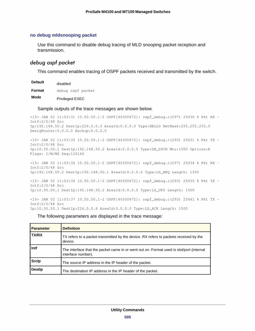
ProSafe M4100 and M7100 Managed Switches
no debug mldsnooping packet
Use this command to disable debug tracing of MLD snooping packet reception and transmission.
debug ospf packet
This command enables tracing of OSPF packets received and transmitted by the switch.
Default
Format debug ospf packet
Mode
Sample outputs of the trace messages are shown below.
<15> JAN 02 11:03:31 10.50.50.1-2 OSPF[46300472]: ospf_debug.c(297) 25430 % Pkt RX - Intf:2/0/48 SrcIp:192.168.50.2 DestIp:224.0.0.5 AreaId:0.0.0.0 Type:HELLO NetMask:255.255.255.0 DesigRouter:0.0.0.0 Backup:0.0.0.0
<15> JAN 02 11:03:35 10.50.50.1-2 OSPF[46300472]: ospf_debug.c(293) 25431 % Pkt TX - Intf:2/0/48 SrcIp:10.50.50.1 DestIp:192.168.50.2 AreaId:0.0.0.0 Type:DB_DSCR Mtu:1500 Options:E Flags: I/M/MS Seq:126166
<15> JAN 02 11:03:36 10.50.50.1-2 OSPF[46300472]: ospf_debug.c(297) 25434 % Pkt RX - Intf:2/0/48 SrcIp:192.168.50.2 DestIp:192.168.50.1 AreaId:0.0.0.0 Type:LS_REQ Length: 1500
<15> JAN 02 11:03:36 10.50.50.1-2 OSPF[46300472]: ospf_debug.c(293) 25435 % Pkt TX - Intf:2/0/48 SrcIp:10.50.50.1 DestIp:192.168.50.2 AreaId:0.0.0.0 Type:LS_UPD Length: 1500
<15> JAN 02 11:03:37 10.50.50.1-2 OSPF[46300472]: ospf_debug.c(293) 25441 % Pkt TX - Intf:2/0/48 SrcIp:10.50.50.1 DestIp:224.0.0.6 AreaId:0.0.0.0 Type:LS_ACK Length: 1500
The following parameters are displayed in the trace message:
disabled
Privileged EXEC
Parameter Definition
TX/RX TX refers to a packet transmitted by the device. RX refers to packets received by the device.
Intf The interface that the packet came in or went out on. Format used is slot/port (internal interface number).
SrcIp The source IP address in the IP header of the packet.
DestIp The destination IP address in the IP header of the packet.
Utility Commands
595
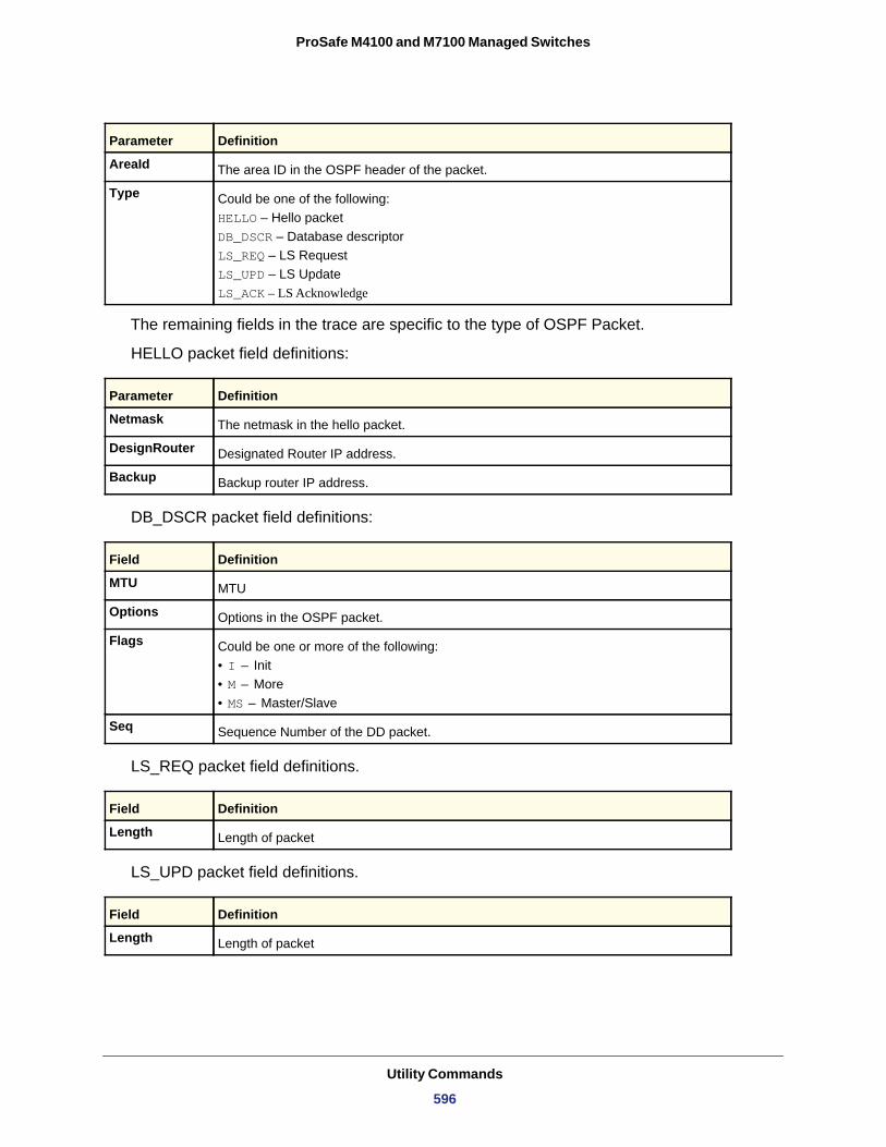
ProSafe M4100 and M7100 Managed Switches
The remaining fields in the trace are specific to the type of OSPF Packet.
HELLO packet field definitions:
Netmask
DesignRouter
Backup
DB_DSCR packet field definitions:
MTU
Options
Flags
• I – Init• M – More• MS – Master/Slave
Seq
LS_REQ packet field definitions.
Length
LS_UPD packet field definitions.
Length
AreaId The area ID in the OSPF header of the packet.
Type Could be one of the following: HELLO – Hello packetDB_DSCR – Database descriptorLS_REQ – LS RequestLS_UPD – LS UpdateLS_ACK – LS Acknowledge
Parameter Definition
The netmask in the hello packet.
Designated Router IP address.
Backup router IP address.
Field Definition
MTU
Options in the OSPF packet.
Could be one or more of the following:
Sequence Number of the DD packet.
Field Definition
Length of packet
Field Definition
Length of packet
Parameter Definition
Utility Commands
596
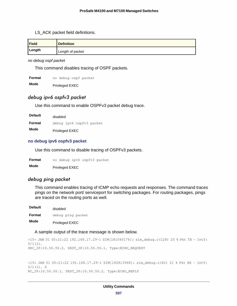
ProSafe M4100 and M7100 Managed Switches
LS_ACK packet field definitions.
Length
no debug ospf packet
This command disables tracing of OSPF packets.
Format no debug ospf packet
Mode
debug ipv6 ospfv3 packet
Use this command to enable OSPFv3 packet debug trace.
Default
Format debug ipv6 ospfv3 packet
Mode
no debug ipv6 ospfv3 packet
Use this command to disable tracing of OSPFv3 packets.
Format no debug ipv6 ospfv3 packet
Mode
debug ping packet
This command enables tracing of ICMP echo requests and responses. The command traces pings on the network port/ serviceport for switching packages. For routing packages, pings are traced on the routing ports as well.
Default
Format debug ping packet
Mode
A sample output of the trace message is shown below.
<15> JAN 01 00:21:22 192.168.17.29-1 SIM[181040176]: sim_debug.c(128) 20 % Pkt TX - Intf: 0/1(1),SRC_IP:10.50.50.2, DEST_IP:10.50.50.1, Type:ECHO_REQUEST
<15> JAN 01 00:21:22 192.168.17.29-1 SIM[182813968]: sim_debug.c(82) 21 % Pkt RX - Intf: 0/1(1), SRC_IP:10.50.50.1, DEST_IP:10.50.50.2, Type:ECHO_REPLY
Field Definition
Length of packet
Privileged EXEC
disabled
Privileged EXEC
Privileged EXEC
disabled
Privileged EXEC
Utility Commands
597
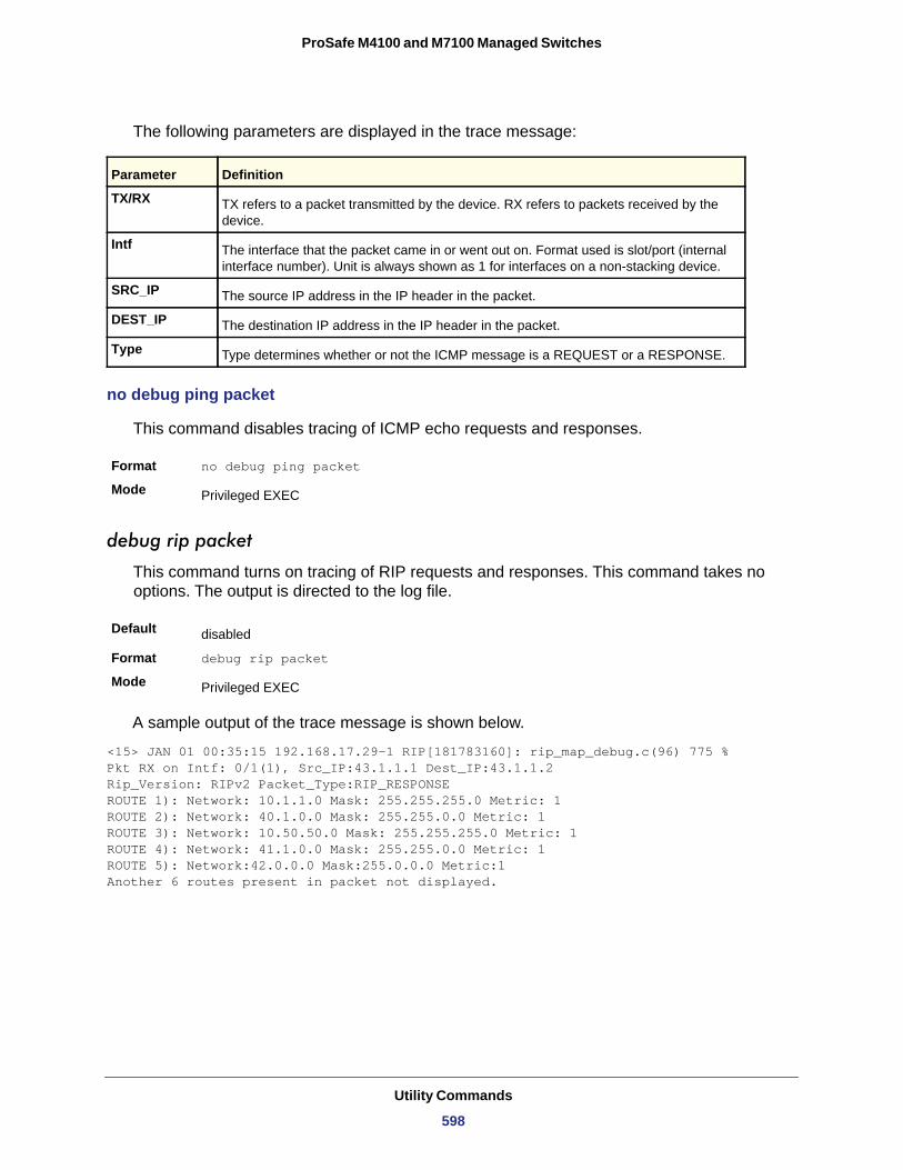
ProSafe M4100 and M7100 Managed Switches
The following parameters are displayed in the trace message:
TX/RX
Intf
SRC_IP
DEST_IP
Type
no debug ping packet
This command disables tracing of ICMP echo requests and responses.
Format no debug ping packet
Mode
debug rip packet
This command turns on tracing of RIP requests and responses. This command takes no options. The output is directed to the log file.
Default
Format debug rip packet
Mode
A sample output of the trace message is shown below.
<15> JAN 01 00:35:15 192.168.17.29-1 RIP[181783160]: rip_map_debug.c(96) 775 % Pkt RX on Intf: 0/1(1), Src_IP:43.1.1.1 Dest_IP:43.1.1.2Rip_Version: RIPv2 Packet_Type:RIP_RESPONSEROUTE 1): Network: 10.1.1.0 Mask: 255.255.255.0 Metric: 1ROUTE 2): Network: 40.1.0.0 Mask: 255.255.0.0 Metric: 1ROUTE 3): Network: 10.50.50.0 Mask: 255.255.255.0 Metric: 1ROUTE 4): Network: 41.1.0.0 Mask: 255.255.0.0 Metric: 1ROUTE 5): Network:42.0.0.0 Mask:255.0.0.0 Metric:1Another 6 routes present in packet not displayed.
Parameter Definition
TX refers to a packet transmitted by the device. RX refers to packets received by the device.
The interface that the packet came in or went out on. Format used is slot/port (internal interface number). Unit is always shown as 1 for interfaces on a non-stacking device.
The source IP address in the IP header in the packet.
The destination IP address in the IP header in the packet.
Type determines whether or not the ICMP message is a REQUEST or a RESPONSE.
Privileged EXEC
disabled
Privileged EXEC
Utility Commands
598
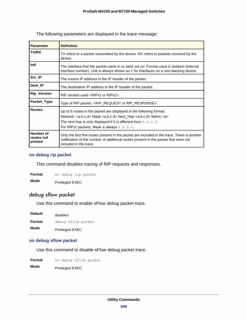
ProSafe M4100 and M7100 Managed Switches
The following parameters are displayed in the trace message:
TX/RX
Intf
Src_IP
Dest_IP
Rip_Version
Packet_Type
Routes
Number of routes not printed
no debug rip packet
This command disables tracing of RIP requests and responses.
Format no debug rip packet
Mode
debug sflow packet
Use this command to enable sFlow debug packet trace.
Default
Format debug sflow packet
Mode
no debug sflow packet
Use this command to disable sFlow debug packet trace.
Format no debug sflow packet
Mode
Parameter Definition
TX refers to a packet transmitted by the device. RX refers to packets received by the device.
The interface that the packet came in or went out on. Format used is slot/port (internal interface number). Unit is always shown as 1 for interfaces on a non-stacking device.
The source IP address in the IP header of the packet.
The destination IP address in the IP header of the packet.
RIP version used <RIPv1 or RIPv2>.
Type of RIP packet. <RIP_REQUEST or RIP_RESPONSE>.
Up to 5 routes in the packet are displayed in the following format:Network: <a.b.c.d> Mask <a.b.c.d> Next_Hop <a.b.c.d> Metric <a>The next hop is only displayed if it is different from 0.0.0.0.For RIPv1 packets, Mask is always 0.0.0.0.
Only the first five routes present in the packet are included in the trace. There is another notification of the number of additional routes present in the packet that were not included in the trace.
Privileged EXEC
disabled
Privileged EXEC
Privileged EXEC
Utility Commands
599
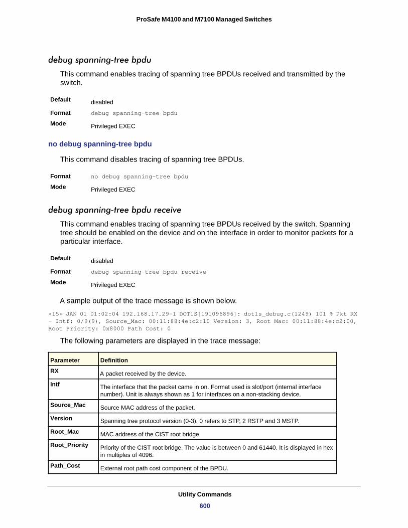
ProSafe M4100 and M7100 Managed Switches
debug spanning-tree bpdu
This command enables tracing of spanning tree BPDUs received and transmitted by the switch.
Default
Format debug spanning-tree bpdu
Mode
no debug spanning-tree bpdu
This command disables tracing of spanning tree BPDUs.
Format no debug spanning-tree bpdu
Mode
debug spanning-tree bpdu receive
This command enables tracing of spanning tree BPDUs received by the switch. Spanning tree should be enabled on the device and on the interface in order to monitor packets for a particular interface.
Default
Format debug spanning-tree bpdu receive
Mode
A sample output of the trace message is shown below.
<15> JAN 01 01:02:04 192.168.17.29-1 DOT1S[191096896]: dot1s_debug.c(1249) 101 % Pkt RX - Intf: 0/9(9), Source_Mac: 00:11:88:4e:c2:10 Version: 3, Root Mac: 00:11:88:4e:c2:00, Root Priority: 0x8000 Path Cost: 0
The following parameters are displayed in the trace message:
RX
Intf
Source_Mac
Version
Root_Mac
Root_Priority
Path_Cost
disabled
Privileged EXEC
Privileged EXEC
disabled
Privileged EXEC
Parameter Definition
A packet received by the device.
The interface that the packet came in on. Format used is slot/port (internal interface number). Unit is always shown as 1 for interfaces on a non-stacking device.
Source MAC address of the packet.
Spanning tree protocol version (0-3). 0 refers to STP, 2 RSTP and 3 MSTP.
MAC address of the CIST root bridge.
Priority of the CIST root bridge. The value is between 0 and 61440. It is displayed in hex in multiples of 4096.
External root path cost component of the BPDU.
Utility Commands
600
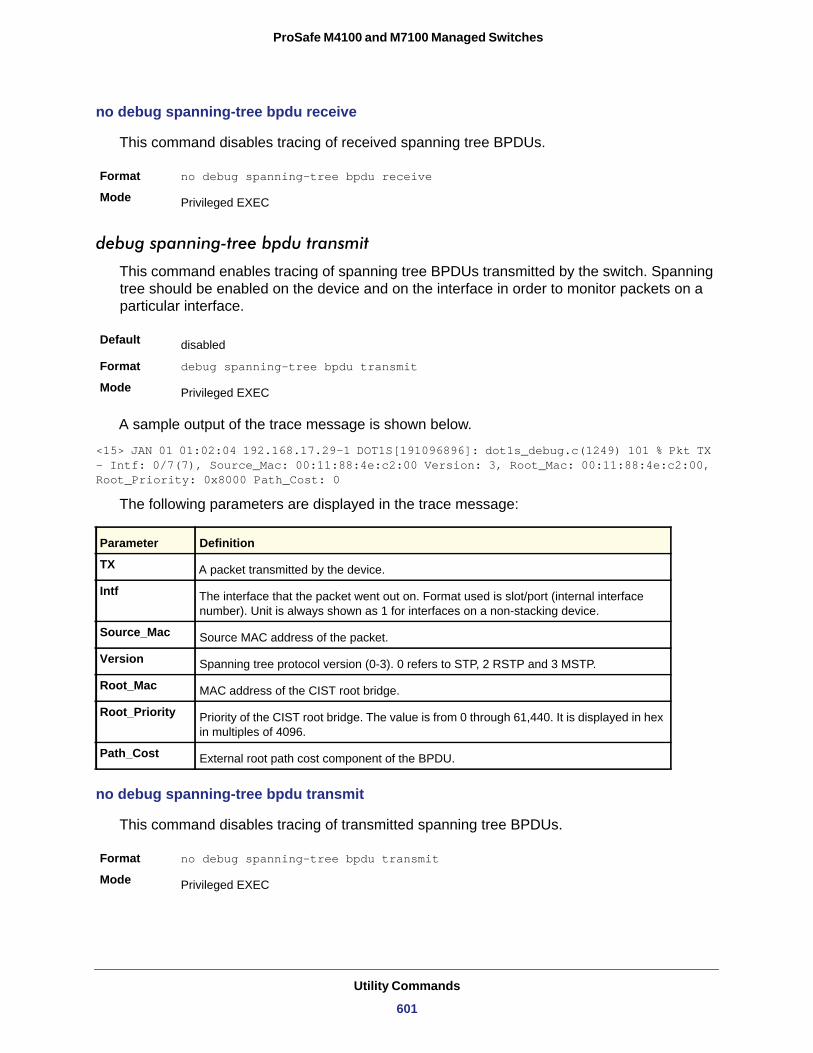
ProSafe M4100 and M7100 Managed Switches
no debug spanning-tree bpdu receive
This command disables tracing of received spanning tree BPDUs.
Format no debug spanning-tree bpdu receive
Mode
debug spanning-tree bpdu transmit
This command enables tracing of spanning tree BPDUs transmitted by the switch. Spanning tree should be enabled on the device and on the interface in order to monitor packets on a particular interface.
Default
Format debug spanning-tree bpdu transmit
Mode
A sample output of the trace message is shown below.
<15> JAN 01 01:02:04 192.168.17.29-1 DOT1S[191096896]: dot1s_debug.c(1249) 101 % Pkt TX - Intf: 0/7(7), Source_Mac: 00:11:88:4e:c2:00 Version: 3, Root_Mac: 00:11:88:4e:c2:00, Root_Priority: 0x8000 Path_Cost: 0
The following parameters are displayed in the trace message:
TX
Intf
Source_Mac
Version
Root_Mac
Root_Priority
Path_Cost
no debug spanning-tree bpdu transmit
This command disables tracing of transmitted spanning tree BPDUs.
Format no debug spanning-tree bpdu transmit
Mode
Privileged EXEC
disabled
Privileged EXEC
Parameter Definition
A packet transmitted by the device.
The interface that the packet went out on. Format used is slot/port (internal interface number). Unit is always shown as 1 for interfaces on a non-stacking device.
Source MAC address of the packet.
Spanning tree protocol version (0-3). 0 refers to STP, 2 RSTP and 3 MSTP.
MAC address of the CIST root bridge.
Priority of the CIST root bridge. The value is from 0 through 61,440. It is displayed in hex in multiples of 4096.
External root path cost component of the BPDU.
Privileged EXEC
Utility Commands
601
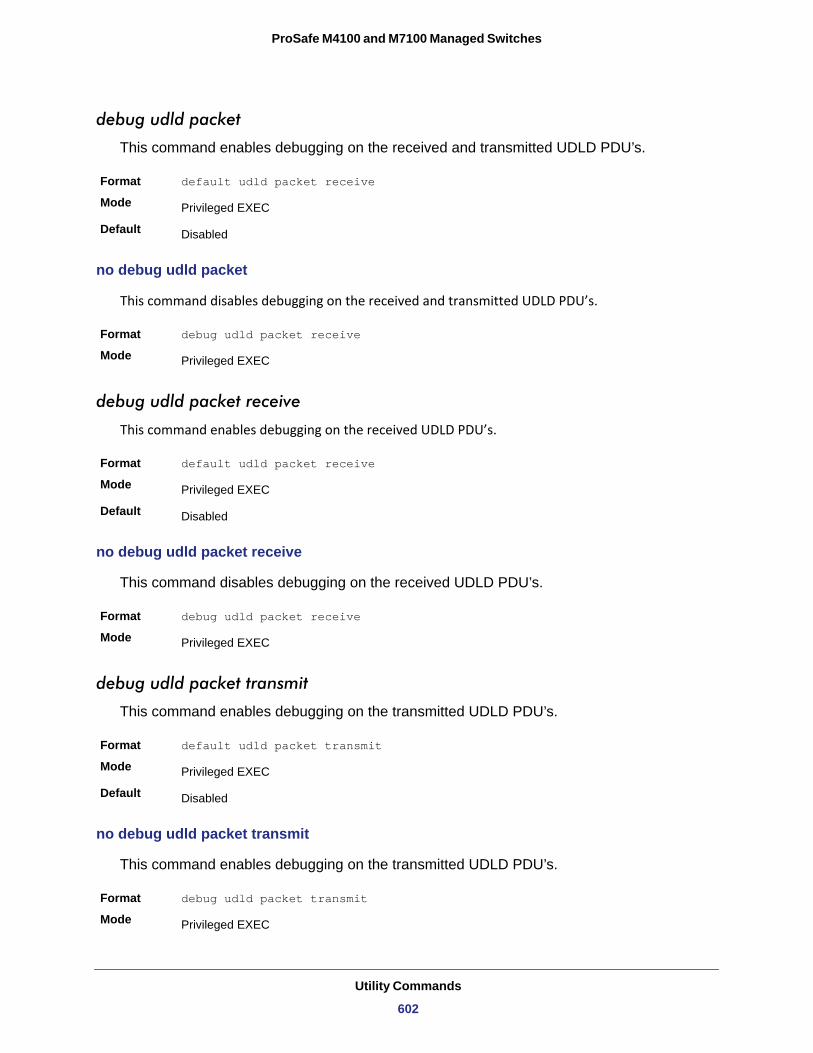
ProSafe M4100 and M7100 Managed Switches
debug udld packet
This command enables debugging on the received and transmitted UDLD PDU’s.
Format default udld packet receive
Mode
Default
no debug udld packet
This command disables debugging on the received and transmitted UDLD PDU’s.
Format debug udld packet receive
Mode
debug udld packet receive
This command enables debugging on the received UDLD PDU’s.
Format default udld packet receive
Mode
Default
no debug udld packet receive
This command disables debugging on the received UDLD PDU’s.
Format debug udld packet receive
Mode
debug udld packet transmit
This command enables debugging on the transmitted UDLD PDU’s.
Format default udld packet transmit
Mode
Default
no debug udld packet transmit
This command enables debugging on the transmitted UDLD PDU’s.
Format debug udld packet transmit
Mode
Privileged EXEC
Disabled
Privileged EXEC
Privileged EXEC
Disabled
Privileged EXEC
Privileged EXEC
Disabled
Privileged EXEC
Utility Commands
602
ProSafe M4100 and M7100 Managed Switches
debug aaa accounting
This command is useful for debugging accounting configuration and functionality in User Manager.
Format debug aaa accounting
Mode
no debug aaa accounting
Use this command to turn off debugging of User Manager accounting functionality.
Format no debug aaa accounting
Mode
debug aaa authorization
This command is useful for debugging authorization configuration and functionality in User Manager.
Format debug aaa authorization [commands|exec]
Mode
no debug aaa authorization
Use this command to turn off debugging of User Manager authorization functionality.
Format no debug aaa authorization
Mode
Cable Test Command
The cable test feature enables you to determine the cable connection status on a selected port.
Note: The cable test feature is supported only for copper cable. It is not supported for optical fiber cable. If the port has an active link while the cable test is run, the link can go down for the duration of the test.
Privileged EXEC
Privileged EXEC
Privileged EXEC
Privileged EXEC
Utility Commands
603
ProSafe M4100 and M7100 Managed Switches
cablestatus
This command returns the status of the specified port.
Format cablestatus <slot/port>
Mode
sFlow Commands
sFlow® is the standard for monitoring high-speed switched and routed networks. sFlow technology is built into network equipment and gives complete visibility into network activity, enabling effective management and control of network resources.
sflow receiver
Use this command to configure the sFlow collector parameters (owner string, receiver timeout, max datagram size, IP address, and port).
Format sflow receiver <rcvr_idx> owner <owner-string> [timeout <rcvr_timeout> | notimeout] max datagram <size> ip/ipv6 <ip> port <port>
Mode
Privileged EXEC
Field Description
Cable Status One of the following statuses is returned:• Normal: The cable is working correctly.• Open: The cable is disconnected or there is a faulty connector.• Short: There is an electrical short in the cable.• Cable Test Failed: The cable status could not be determined. The cable may in fact
be working.
Cable Length If this feature is supported by the PHY for the current link speed, the cable length is displayed as a range between the shortest estimated length and the longest estimated length. Note that if the link is down and a cable is attached to a 10/100 Ethernet adapter, then the cable status may display as Open or Short because some Ethernet adapters leave unused wire pairs unterminated or grounded. Unknown is displayed if the cable length could not be determined.
Global Config
Utility Commands
604
ProSafe M4100 and M7100 Managed Switches
no sflow receiver
Use this command to set the sFlow collector parameters back to the defaults.
Format no sflow receiver <indx> {ip <ip-address> | maxdatagram <size> | owner <string> timeout <interval> | port <14-port>}
Mode
sflow sampler
A data source configured to collect flow samples is called a poller. Use this command to configure a new sFlow sampler instance for this data source if <rcvr_idx> is valid.
Format sflow sampler {<rcvr-indx> | rate <sampling-rate> | maxheadersize <size>}
Mode
Field Description
Receiver Owner The identity string for the receiver, the entity making use of this sFlowRcvrTable entry. The range is 127 characters. The default is a null string. The empty string indicates that the entry is currently unclaimed and the receiver configuration is reset to the default values. An entity wishing to claim an sFlowRcvrTable entry must ensure that the entry is unclaimed before trying to claim it. The entry is claimed by setting the owner string to a non-null value. The entry must be claimed before assigning a receiver to a sampler or poller.
Receiver Timeout The time, in seconds, remaining before the sampler or poller is released and stops
sending samples to receiver. A management entity wanting to maintain control of the sampler is responsible for setting a new value before the old one expires. The allowed range is 0-4294967295 seconds. The default is zero (0).
Receiver Max Datagram Size The maximum number of data bytes that can be sent in a single sample datagram. The
management entity should set this value to avoid fragmentation of the sFlow datagrams. The allowed range is 200 –9,116). The default is 1400.
Receiver IP The sFlow receiver IP address. If set to 0.0.0.0, no sFlow datagrams will be sent. The default is 0.0.0.0.
Receiver Port The destination Layer4 UDP port for sFlow datagrams. The range is 1-65535. The default is 6343.
Global Config
Interface Config
Utility Commands
605

ProSafe M4100 and M7100 Managed Switches
no sflow sampler
Use this command to reset the sFlow sampler instance to the default settings.
Format no sflow sampler {<rcvr-indx> | rate <sampling-rate> | maxheadersize <size>}
Mode
sflow poller
A data source configured to collect counter samples is called a poller. Use this command to enable a new sFlow poller instance for this data source if <rcvr_idx> is valid.
Format sflow poller {<rcvr-indx> | interval <poll-interval>}
Mode
no sflow poller
Use this command to reset the sFlow poller instance to the default settings.
Format no sflow poller {<rcvr-indx> | interval <poll-interval>}
Mode
Field Description
Receiver Index The sFlow Receiver for this sFlow sampler to which flow samples are to be sent. A value of zero (0) means that no receiver is configured, no packets will be sampled. Only active receivers can be set. If a receiver expires, then all samplers associated with the receiver will also expire. Possible values are 1-8. The default is 0.
Maxheadersize The maximum number of bytes that should be copied from the sampler packet. The range is 20-256. The default is 128. When set to zero (0), all the sampler parameters are set to their corresponding default value.
Sampling Rate The statistical sampling rate for packet sampling from this source. A sampling rate of 1 counts all packets. A value of zero (0) disables sampling. A value of N means that out of N incoming packets, 1 packet will be sampled. The range is 1024-65536 and 0. The default is 0.
Interface Config
Interface Config
Field Description
Receiver Index Enter the sFlow Receiver associated with the sampler/poller. A value of zero (0) means that no receiver is configured. The range is 1-8. The default is 0.
Poll Interval Enter the sFlow instance polling interval. A poll interval of zero (0) disables counter sampling. When set to zero (0), all the poller parameters are set to their corresponding default value. The range is 0-86400. The default is 0. A value of N means once in N seconds a counter sample is generated.
Interface Config
Utility Commands
606
ProSafe M4100 and M7100 Managed Switches
show sflow agent
The sFlow agent collects time-based sampling of network interface statistics and flow-based samples. These are sent to the configured sFlow receivers. Use this command to display the sFlow agent information.
Format show sflow agent
Mode
Example: The following shows example CLI display output for the command.
(switch) #show sflow agent
sFlow Version.................................. 1.3;Netgear;1.0IP Address..................................... 10.131.12.66
show sflow pollers
Use this command to display the sFlow polling instances created on the switch. Use “-” for range.
Format show sflow pollers
Mode
Privileged EXEC
Field Description
sFlow Version Uniquely identifies the version and implementation of this MIB. The version string must have the following structure: MIB Version; Organization; Software Revision where:• MIB Version: ‘1.3’, the version of this MIB.• Organization: Netgear.• Revision: 1.0
IP Address The IP address associated with this agent.
Privileged EXEC
Field Description
Poller Data Source The sFlowDataSource (slot/port) for this sFlow sampler. This agent will support Physical
ports only.
Receiver Index The sFlowReceiver associated with this sFlow counter poller.
Poller Interval The number of seconds between successive samples of the counters associated with this data source.
Utility Commands
607
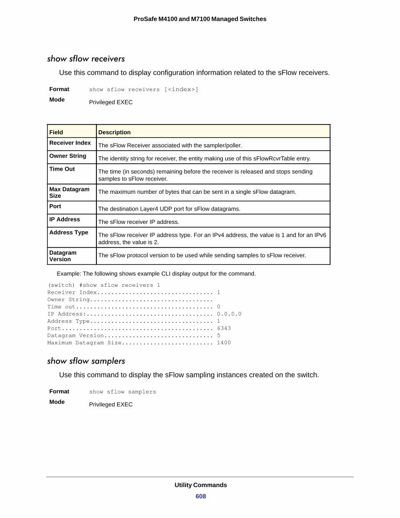
ProSafe M4100 and M7100 Managed Switches
show sflow receivers
Use this command to display configuration information related to the sFlow receivers.
Format show sflow receivers [<index>]
Mode
Example: The following shows example CLI display output for the command.
(switch) #show sflow receivers 1Receiver Index................................. 1Owner String...................................Time out....................................... 0IP Address:.................................... 0.0.0.0Address Type................................... 1Port........................................... 6343Datagram Version............................... 5Maximum Datagram Size.......................... 1400
show sflow samplers
Use this command to display the sFlow sampling instances created on the switch.
Format show sflow samplers
Mode
Privileged EXEC
Field Description
Receiver Index The sFlow Receiver associated with the sampler/poller.
Owner String The identity string for receiver, the entity making use of this sFlowRcvrTable entry.
Time Out The time (in seconds) remaining before the receiver is released and stops sending samples to sFlow receiver.
Max Datagram Size The maximum number of bytes that can be sent in a single sFlow datagram.
Port The destination Layer4 UDP port for sFlow datagrams.
IP Address The sFlow receiver IP address.
Address Type The sFlow receiver IP address type. For an IPv4 address, the value is 1 and for an IPv6 address, the value is 2.
Datagram Version The sFlow protocol version to be used while sending samples to sFlow receiver.
Privileged EXEC
Utility Commands
608
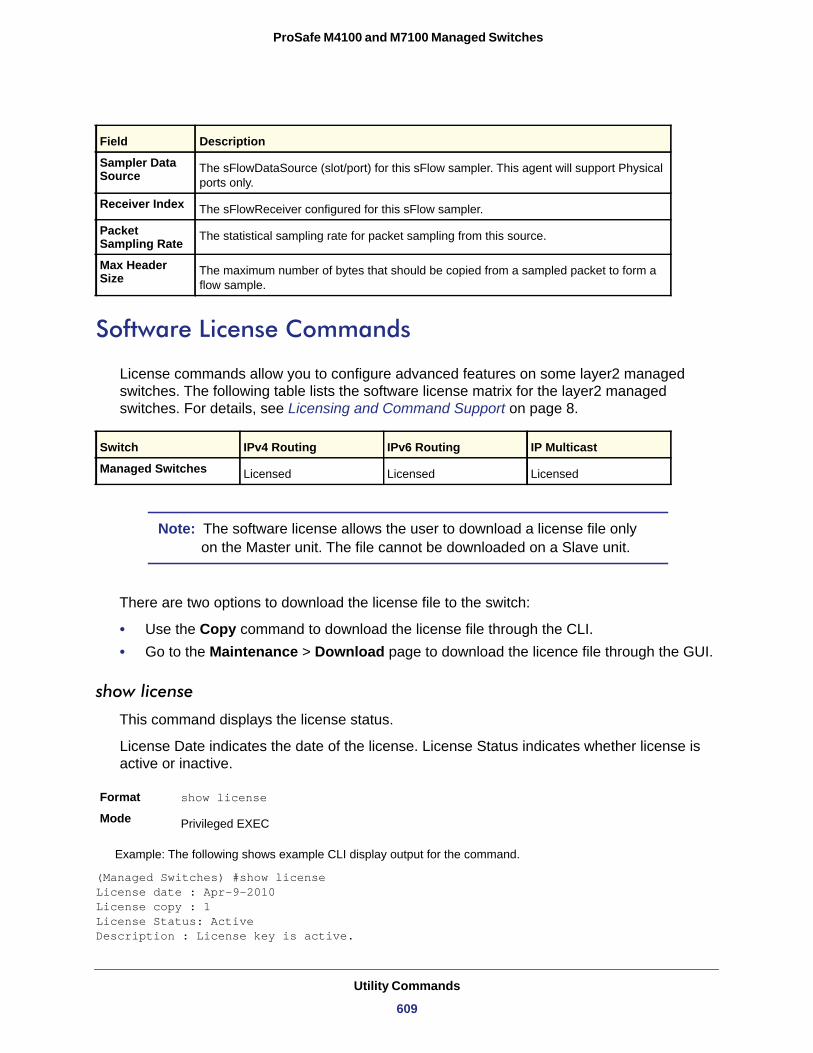
ProSafe M4100 and M7100 Managed Switches
Software License Commands
License commands allow you to configure advanced features on some layer2 managed switches. The following table lists the software license matrix for the layer2 managed switches. For details, see Licensing and Command Support on page 8.
Managed Switches
Note: The software license allows the user to download a license file only on the Master unit. The file cannot be downloaded on a Slave unit.
There are two options to download the license file to the switch:
• Use the Copy command to download the license file through the CLI.• Go to the Maintenance > Download page to download the licence file through the GUI.
show license
This command displays the license status.
License Date indicates the date of the license. License Status indicates whether license is active or inactive.
Format show license
Mode
Example: The following shows example CLI display output for the command.
(Managed Switches) #show licenseLicense date : Apr-9-2010 License copy : 1 License Status: Active Description : License key is active.
Field Description
Sampler Data Source The sFlowDataSource (slot/port) for this sFlow sampler. This agent will support Physical
ports only.
Receiver Index The sFlowReceiver configured for this sFlow sampler.
Packet Sampling Rate The statistical sampling rate for packet sampling from this source.
Max Header Size The maximum number of bytes that should be copied from a sampled packet to form a
flow sample.
Switch IPv4 Routing IPv6 Routing IP Multicast
Licensed Licensed Licensed
Privileged EXEC
Utility Commands
609
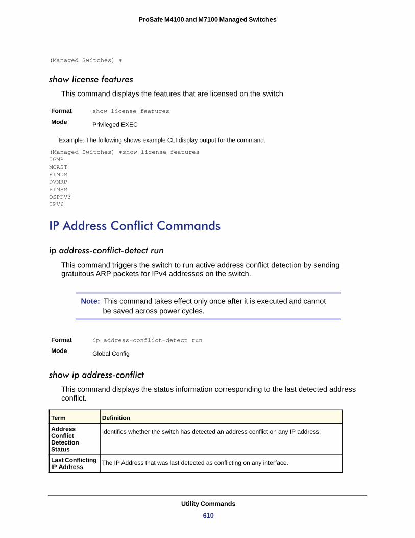
ProSafe M4100 and M7100 Managed Switches
(Managed Switches) #
show license features
This command displays the features that are licensed on the switch
Format show license features
Mode
Example: The following shows example CLI display output for the command.
(Managed Switches) #show license featuresIGMP MCAST PIMDM DVMRP PIMSM OSPFV3 IPV6
IP Address Conflict Commands
ip address-conflict-detect run
This command triggers the switch to run active address conflict detection by sending gratuitous ARP packets for IPv4 addresses on the switch.
Note: This command takes effect only once after it is executed and cannot be saved across power cycles.
Format ip address-conflict-detect run
Mode
show ip address-conflict
This command displays the status information corresponding to the last detected address conflict.
Privileged EXEC
Global Config
Term Definition
Address Conflict Detection Status
Identifies whether the switch has detected an address conflict on any IP address.
Last Conflicting IP Address The IP Address that was last detected as conflicting on any interface.
Utility Commands
610
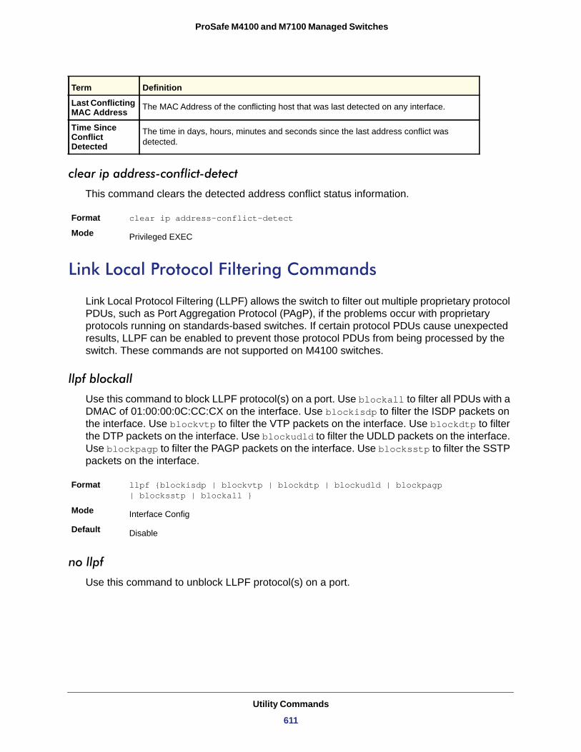
ProSafe M4100 and M7100 Managed Switches
clear ip address-conflict-detect
This command clears the detected address conflict status information.
Format clear ip address-conflict-detect
Mode
Link Local Protocol Filtering Commands
Link Local Protocol Filtering (LLPF) allows the switch to filter out multiple proprietary protocol PDUs, such as Port Aggregation Protocol (PAgP), if the problems occur with proprietary protocols running on standards-based switches. If certain protocol PDUs cause unexpected results, LLPF can be enabled to prevent those protocol PDUs from being processed by the switch. These commands are not supported on M4100 switches.
llpf blockall
Use this command to block LLPF protocol(s) on a port. Use blockall to filter all PDUs with a DMAC of 01:00:00:0C:CC:CX on the interface. Use blockisdp to filter the ISDP packets on the interface. Use blockvtp to filter the VTP packets on the interface. Use blockdtp to filter the DTP packets on the interface. Use blockudld to filter the UDLD packets on the interface. Use blockpagp to filter the PAGP packets on the interface. Use blocksstp to filter the SSTP packets on the interface.
Format llpf {blockisdp | blockvtp | blockdtp | blockudld | blockpagp| blocksstp | blockall }
Mode
Default
no llpf
Use this command to unblock LLPF protocol(s) on a port.
Last Conflicting MAC Address The MAC Address of the conflicting host that was last detected on any interface.
Time Since Conflict Detected
The time in days, hours, minutes and seconds since the last address conflict was detected.
Privileged EXEC
Interface Config
Disable
Term Definition
Utility Commands
611
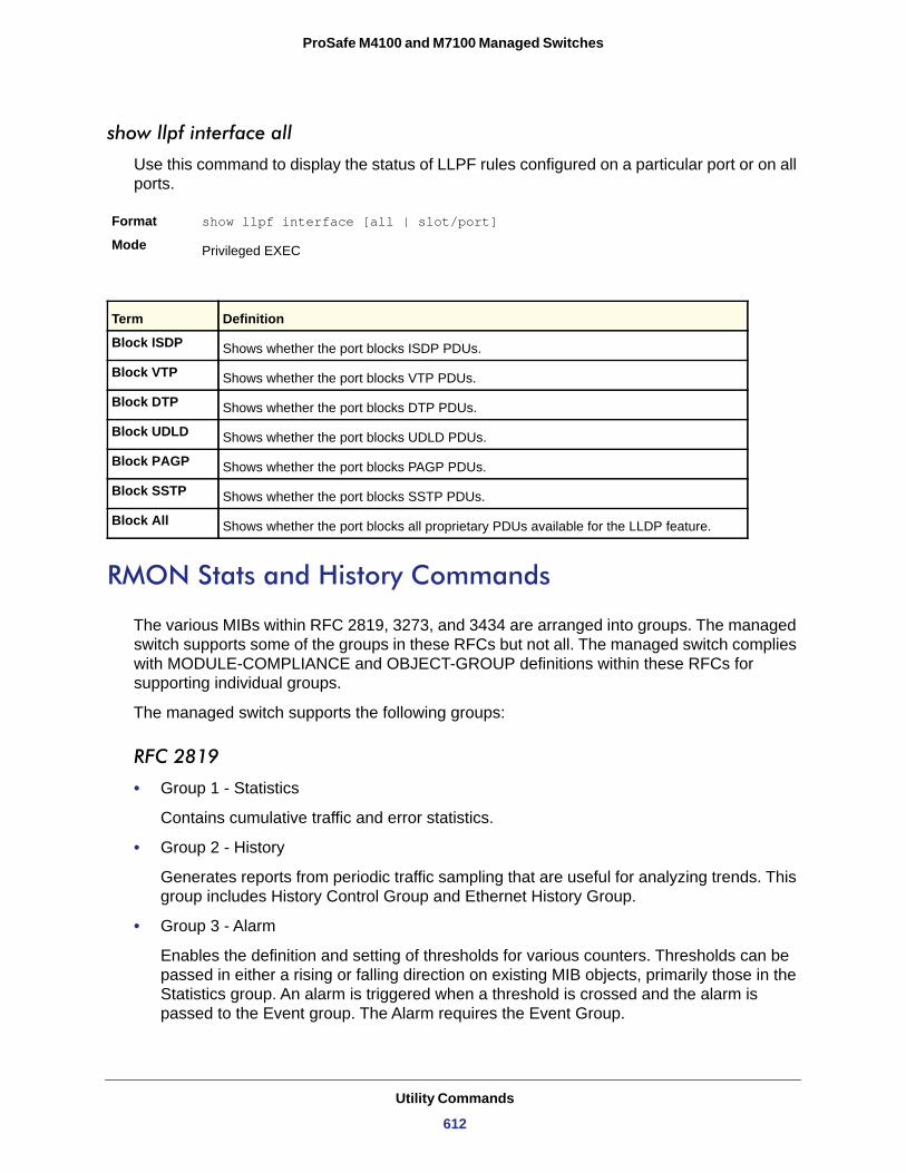
ProSafe M4100 and M7100 Managed Switches
show llpf interface all
Use this command to display the status of LLPF rules configured on a particular port or on all ports.
Format show llpf interface [all | slot/port]
Mode
RMON Stats and History Commands
The various MIBs within RFC 2819, 3273, and 3434 are arranged into groups. The managed switch supports some of the groups in these RFCs but not all. The managed switch complies with MODULE-COMPLIANCE and OBJECT-GROUP definitions within these RFCs for supporting individual groups.
The managed switch supports the following groups:
RFC 2819
• Group 1 - Statistics
Contains cumulative traffic and error statistics.
• Group 2 - History
Generates reports from periodic traffic sampling that are useful for analyzing trends. This group includes History Control Group and Ethernet History Group.
• Group 3 - Alarm
Enables the definition and setting of thresholds for various counters. Thresholds can be passed in either a rising or falling direction on existing MIB objects, primarily those in the Statistics group. An alarm is triggered when a threshold is crossed and the alarm is passed to the Event group. The Alarm requires the Event Group.
Privileged EXEC
Term Definition
Block ISDP Shows whether the port blocks ISDP PDUs.
Block VTP Shows whether the port blocks VTP PDUs.
Block DTP Shows whether the port blocks DTP PDUs.
Block UDLD Shows whether the port blocks UDLD PDUs.
Block PAGP Shows whether the port blocks PAGP PDUs.
Block SSTP Shows whether the port blocks SSTP PDUs.
Block All Shows whether the port blocks all proprietary PDUs available for the LLDP feature.
Utility Commands
612
ProSafe M4100 and M7100 Managed Switches
• Group 9 - Event
Controls the actions that are taken when an event occurs. RMON events occur when:
• A threshold (alarm) is exceeded• There is a match on certain filters.
RFC 3273
• Group 1 - Media Independent Group
Contains media-independent statistics that provide information for full and/or half-duplex links as well as high capacity links.
• Group 2 - Ether Stats High Capacity Group
Contains the High Capacity RMON extensions to RMON-1 etherStatsTable (RFC 2819 Group 1).
• Group 3 - Ether History High Capacity Group
Contains the High Capacity RMON extensions to RMON-1 etherHistoryTable (RFC 2819 Group 2).
RFC 3434
• Group 1 - High Capacity Alarm Control Group
Controls the configuration of alarms for high capacity MIB object instances.
• Group 2 - High Capacity Alarm Capabilities Group
Describes the high capacity alarm capabilities provided by the agent.
• Group 3 - High Capacity Alarm Notifications Group
Provides new rising and falling threshold notifications for high capacity objects.
rmon alarm
This command sets the RMON alarm entry in the RMON alarm MIB group.
Format rmon alarm alarm number variable sample interval sampling type rising-threshold value falling-threshold value startup rising/falling/rising-falling owner string
Mode Global Config
Parameter Description
Alarm Number The Alarm number which identifies an Alarm.
Alarm Variable The object identifier of the particular variable to be sampled. Only variables that resolve to an ASN.1 primitive type of integer.
Utility Commands
613
ProSafe M4100 and M7100 Managed Switches
no rmon alarm
This command deletes the rmon alarm entry.
Format no rmon alarm <alarm number>
Mode
rmon hcalarm
This command sets the rmon hcalarm entry in the High Capacity RMON alarm mib group.
Format rmon hcalarm <alarm number> <variable> <sample interval> <sampling type> rising-threshold high <value> low <value> falling-threshold high <value> low <value> startup <rising/falling/rising-falling> owner <string>
Mode
Sample Interval The interval in seconds over which the data is sampled and compared with the rising and falling thresholds. The range is 0 to 2147483647. The default is 0.
Alarm Sample Type The alarm sample type. The method of sampling the selected variable and calculating the value to be compared against thresholds. Possible types are Absolute or Delta.
Alarm Rising Threshold Value
The alarm rising threshold for the sample statistics.
Alarm Falling Threshold Value
The alarm falling threshold for the sample statistics.
Alarm Startup Alarm
The alarm that may be sent. Possible values are Rising Alarm, Falling Alarm or both.
Alarm Owner string The alarm owner. The owner string associated with the alarm entry.
Global Config
Global Config
Parameter Description
hcalarm alarm number
The identifier of the hcalarm instance.
High Capacity Alarm Variable
The object identifier of the particular variable to be sampled. Only variables that resolve to an ASN.1 primitive type of integer.
High Capacity Alarm interval
The interval in seconds over which the data is sampled and compared with the rising and falling thresholds. The range is 1to 2147483647.
High Capacity Alarm Sample Type
The method of sampling the selected variable and calculating the value to be compared against thresholds. Possible types are Absolute or Delta.
Rising-Threshold High Value
High capacity alarm rising threshold absolute value high. The upper 32 bits of the absolute value for threshold for the sampled statistics.
Parameter Description
Utility Commands
614
ProSafe M4100 and M7100 Managed Switches
no rmon hcalarm
This command deletes the rmon hcalarm entry.
Format no rmon hcalarm <alarm number>
Mode
rmon event
This command sets the rmon event entry in the RMON event mib group.
Format rmon event <event number> [description|log|owner|trap]Mode
• None • Log • SNMP Trap • Log and SNMP Trap
no rmon event
This command deletes the rmon event entry.
Format no rmon event <event number>
Mode
Rising-Threshold Low Value
High capacity alarm rising threshold absolute value low. The lower 32 bits of the absolute value for threshold for the sampled statistics.
Falling-Threshold High Value
High capacity alarm falling threshold absolute value high. The upper 32 bits of the absolute value for threshold for the sampled statistic.
Falling-Threshold Low Value
High capacity alarm falling threshold absolute value high. The upper 32 bits of the absolute value for threshold for the sampled statistic.
Rising/Falling/ Rising-Falling
High capacity alarm startup alarm that may be sent. Possible values are Rising Alarm, Falling Alarm or both.
Owner String High capacity alarm owner. The owner string associated with the entry.
Global Config
Global Config
Parameter Description
Event Number Event identifier
Event Type The type of notification that the probe will make about the event. Possible values are:
Global Config
Parameter Description
Utility Commands
615
ProSafe M4100 and M7100 Managed Switches
rmon collection history
This command sets the history control parameters of the RMON historyControl mib group.
Format rmon collection history <index number> buckets <1-65535> | interval <1-3600> | owner <owner>
Mode
no rmon collection history
This command deletes the history control group entry with the specified index number.
Format no rmon collection history <index number>
Mode
show rmon
This command displays the entries in the RMON alarm table.
Format show rmon {alarms | alarm <alarm-index>}
Mode
show rmon collection history
This command displays the entries in the RMON history control table.
Format show rmon collection history
Mode
show rmon events
This command displays the entries in the RMON event table.
Format show rmon events
Mode
Example:
(Switch) # show rmon events
Index Description Type Community Owner Last time sent-------------------------------------------------------------------------------1 test log public MIB 0 days 0 h:0 m:0 s
Interface Config
Interface Config
Privileged Exec
Privileged Exec
Privileged Exec
Utility Commands
616
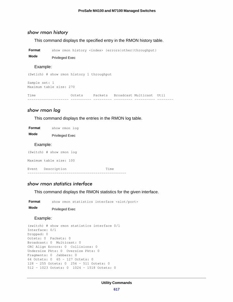
ProSafe M4100 and M7100 Managed Switches
show rmon history
This command displays the specified entry in the RMON history table.
Format show rmon history <index> {errors|other|throughput}
Mode
Example:
(Swtich) # show rmon history 1 throughput
Sample set: 1Maximum table size: 270
Time Octets Packets Broadcast Multicast Util-------------------- ---------- --------- --------- ---------- --------
show rmon log
This command displays the entries in the RMON log table.
Format show rmon log
Mode
Example:
(Switch) # show rmon log
Maximum table size: 100
Event Description Time------------------------------------------------
show rmon statistics interface
This command displays the RMON statistics for the given interface.
Format show rmon statistics interface <slot/port>
Mode
Example:
(switch) # show rmon statistics interface 0/1Interface: 0/1Dropped: 0Octets: 0 Packets: 0Broadcast: 0 Multicast: 0CRC Align Errors: 0 Collisions: 0Undersize Pkts: 0 Oversize Pkts: 0Fragments: 0 Jabbers: 064 Octets: 0 65 - 127 Octets: 0128 - 255 Octets: 0 256 - 511 Octets: 0512 - 1023 Octets: 0 1024 - 1518 Octets: 0
Privileged Exec
Privileged Exec
Privileged Exec
Utility Commands
617
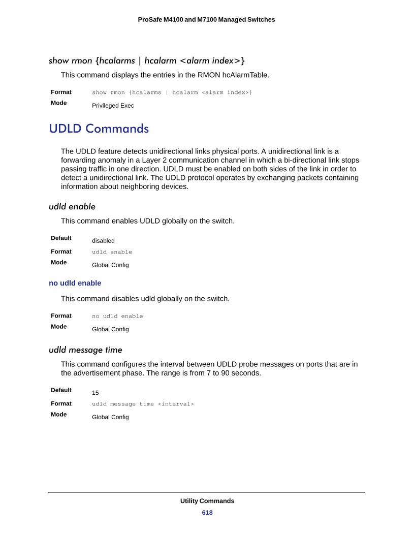
ProSafe M4100 and M7100 Managed Switches
show rmon {hcalarms | hcalarm <alarm index>}
This command displays the entries in the RMON hcAlarmTable.
Format show rmon {hcalarms | hcalarm <alarm index>}
Mode
UDLD Commands
The UDLD feature detects unidirectional links physical ports. A unidirectional link is a forwarding anomaly in a Layer 2 communication channel in which a bi-directional link stops passing traffic in one direction. UDLD must be enabled on both sides of the link in order to detect a unidirectional link. The UDLD protocol operates by exchanging packets containing information about neighboring devices.
udld enable
This command enables UDLD globally on the switch.
Default
Format udld enable
Mode
no udld enable
This command disables udld globally on the switch.
Format no udld enable
Mode
udld message time
This command configures the interval between UDLD probe messages on ports that are in the advertisement phase. The range is from 7 to 90 seconds.
Default
Format udld message time <interval>
Mode
Privileged Exec
disabled
Global Config
Global Config
15
Global Config
Utility Commands
618
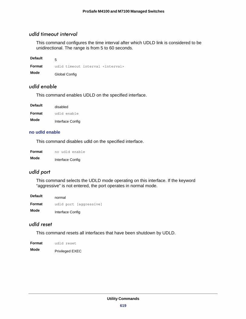
ProSafe M4100 and M7100 Managed Switches
udld timeout interval
This command configures the time interval after which UDLD link is considered to be unidirectional. The range is from 5 to 60 seconds.
Default
Format udld timeout interval <interval>
Mode
udld enable
This command enables UDLD on the specified interface.
Default
Format udld enable
Mode
no udld enable
This command disables udld on the specified interface.
Format no udld enable
Mode
udld port
This command selects the UDLD mode operating on this interface. If the keyword “aggressive” is not entered, the port operates in normal mode.
Default
Format udld port [aggressive]
Mode
udld reset
This command resets all interfaces that have been shutdown by UDLD.
Format udld reset
Mode
5
Global Config
disabled
Interface Config
Interface Config
normal
Interface Config
Privileged EXEC
Utility Commands
619
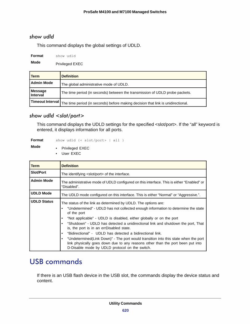
ProSafe M4100 and M7100 Managed Switches
show udld
This command displays the global settings of UDLD.
Format show udld
Mode
Admin Mode
Message Interval
Timeout Interval
show udld <slot/port>
This command displays the UDLD settings for the specified <slot/port>. If the “all” keyword is entered, it displays information for all ports.
Format show udld {< slot/port> | all }
Mode • Privileged EXEC• User EXEC
Slot/Port
Admin Mode
UDLD Mode
UDLD Status
• “Undetermined” - UDLD has not collected enough information to determine the state of the port
• “Not applicable” - UDLD is disabled, either globally or on the port• “Shutdown” - UDLD has detected a unidirectional link and shutdown the port, That
is, the port is in an errDisabled state.• “Bidirectional” - UDLD has detected a bidirectional link.• “Undetermined(Link Down)” - The port would transition into this state when the port
link physically goes down due to any reasons other than the port been put into D-Disable mode by UDLD protocol on the switch.
USB commands
If there is an USB flash device in the USB slot, the commands display the device status and content.
Privileged EXEC
Term Definition
The global administrative mode of UDLD.
The time period (in seconds) between the transmission of UDLD probe packets.
The time period (in seconds) before making decision that link is unidirectional.
Term Definition
The identifying <slot/port> of the interface.
The administrative mode of UDLD configured on this interface. This is either “Enabled” or “Disabled”.
The UDLD mode configured on this interface. This is either “Normal” or “Aggressive.”.
The status of the link as determined by UDLD. The options are:
Utility Commands
620
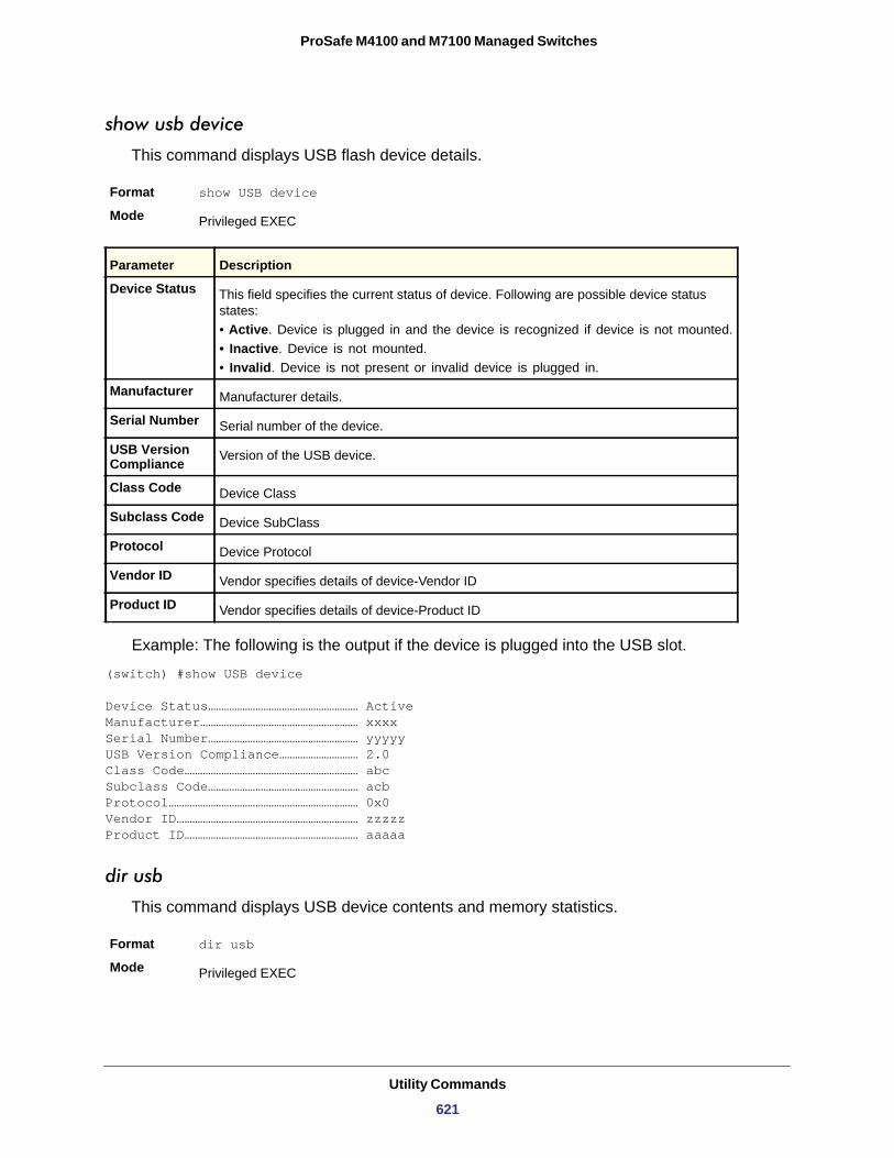
ProSafe M4100 and M7100 Managed Switches
show usb device
This command displays USB flash device details.
Format show USB device
Mode
Device Status
• Active. Device is plugged in and the device is recognized if device is not mounted.• Inactive. Device is not mounted.• Invalid. Device is not present or invalid device is plugged in.
Manufacturer
Serial Number
USB Version Compliance
Class Code
Subclass Code
Protocol
Vendor ID
Product ID
Example: The following is the output if the device is plugged into the USB slot.
(switch) #show USB device
Device Status………………………………………………… ActiveManufacturer…………………………………………………… xxxxSerial Number………………………………………………… yyyyyUSB Version Compliance………………………… 2.0Class Code………………………………………………………… abcSubclass Code………………………………………………… acbProtocol……………………………………………………………… 0x0Vendor ID…………………………………………………………… zzzzzProduct ID………………………………………………………… aaaaa
dir usb
This command displays USB device contents and memory statistics.
Format dir usb
Mode
Privileged EXEC
Parameter Description
This field specifies the current status of device. Following are possible device status states:
Manufacturer details.
Serial number of the device.
Version of the USB device.
Device Class
Device SubClass
Device Protocol
Vendor specifies details of device-Vendor ID
Vendor specifies details of device-Product ID
Privileged EXEC
Utility Commands
621
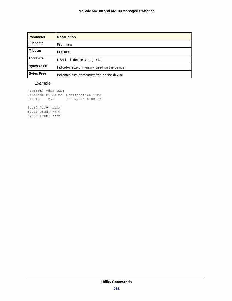
ProSafe M4100 and M7100 Managed Switches
Filename
Filesize
Total Size
Bytes Used
Bytes Free
Example:
(switch) #dir USB:Filename Filesize Modification TimeF1.cfg 256 4/22/2009 8:00:12
Total Size: xxxxBytes Used: yyyyBytes Free: zzzz
Parameter Description
File name
File size
USB flash device storage size
Indicates size of memory used on the device.
Indicates size of memory free on the device
Utility Commands
622
11
11. Management CommandsThis chapter describes the management commands available in the managed switch CLI.
This chapter contains the following sections:
• Configuring the Switch Management CPU • Network Interface Commands • Console Port Access Commands • Telnet Commands • Secure Shell (SSH) Commands • Management Security Commands • Hypertext Transfer Protocol (HTTP) Commands • Access Commands • User Account Commands • SNMP Commands • RADIUS Commands • TACACS+ Commands • Configuration Scripting Commands • Pre-Login Banner and System Prompt Commands • Switch Database Management (SDM) Templates • IPv6 Management Commands
The commands in this chapter are in three functional groups:
• Show commands display switch settings, statistics, and other information.• Configuration commands configure features and options of the switch. Every switch
command has a show command that displays the configuration setting.• Clear commands clear some or all of the settings to factory defaults.
623
ProSafe M4100 and M7100 Managed Switches
Configuring the Switch Management CPU
To manage the switch via the web GUI or telnet, an IP address needs to be assigned to the switch management CPU. Whereas there are CLI commands that can be used to do this, ezconfig simplifies the task. The tool is applicable to all NETGEAR 7000-series managed switches, and allows you to configure the following parameters:
1. The administrator’s user password and administrator-enable password2. Management CPU IP address and network mask3. System name and location information
The tool is interactive and uses questions to guide you through the steps required to perform its task. At the end of the session, it will ask you if you want to save the changed information. To see exactly what has been changed by ezconfig at the end of the session, use the show running-config command.
To perform any switch configuration other than the items listed above, use other CLI commands or the web GUI.
ezconfig
This command sets the IP address, subnet mask, and gateway of the device. The IP address and the gateway must be on the same subnet.
Format ezconfig
Mode Privileged EXEC
Management Commands
624
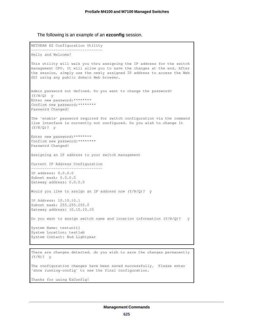
ProSafe M4100 and M7100 Managed Switches
The following is an example of an ezconfig session.
NETGEAR EZ Configuration Utility--------------------------------Hello and Welcome!
This utility will walk you thru assigning the IP address for the switch management CPU. It will allow you to save the changes at the end. After the session, simply use the newly assigned IP address to access the Web GUI using any public domain Web browser.
Admin password not defined. Do you want to change the password? (Y/N/Q) yEnter new password:******** Confirm new password:******** Password Changed!
The 'enable' password required for switch configuration via the command line interface is currently not configured. Do you wish to change it (Y/N/Q)? y
Enter new password:******** Confirm new password:******** Password Changed!
Assigning an IP address to your switch management
Current IP Address Configuration -------------------------------- IP address: 0.0.0.0 Subnet mask: 0.0.0.0Gateway address: 0.0.0.0
Would you like to assign an IP address now (Y/N/Q)? y
IP Address: 10.10.10.1 Subnet mask: 255.255.255.0Gateway address: 10.10.10.10
Do you want to assign switch name and location information (Y/N/Q)? y
System Name: testunit1 System Location: testlab System Contact: Bud Lightyear
There are changes detected, do you wish to save the changes permanently (Y/N)? y
The configuration changes have been saved successfully. Please enter 'show running-config' to see the final configuration.
Thanks for using EzConfig!
Management Commands
625
ProSafe M4100 and M7100 Managed Switches
Network Interface Commands
This section describes the commands you use to configure a logical interface for management access. To configure the management VLAN, see step on page 47.
enable (Privileged EXEC access)
Use this command to access the Privileged EXEC mode. From the Privileged EXEC mode, you can configure the network interface.
Format enable
Mode
network parms
Use this command to set the IP address, subnet mask, and gateway of the device. The IP address and the gateway must be on the same subnet.
Format network parms <ipaddr> <netmask> [<gateway>]
Mode
network protocol
Use this command to specify the network configuration protocol to be used. If you modify this value, change is effective immediately. If you use the bootp parameter, the switch periodically sends requests to a BootP server until a response is received. If you use the dhcp parameter, the switch periodically sends requests to a DHCP server until a response is received. If you use the none parameter, you must configure the network information for the switch manually.
Default
Format network protocol {none | bootp | dhcp}
Mode
network mac-address
Use this command to set locally administered MAC addresses. The following rules apply:
• Bit 6 of byte 0 (called the U/L bit) indicates whether the address is universally administered (b'0') or locally administered (b'1').
• Bit 7 of byte 0 (called the I/G bit) indicates whether the destination address is an individual address (b'0') or a group address (b'1').
• The second character, of the twelve character macaddr, must be 2, 6, A or E.
User EXEC
Privileged EXEC
none
Privileged EXEC
Management Commands
626
ProSafe M4100 and M7100 Managed Switches
A locally administered address must have bit 6 On (b'1') and bit 7 Off (b'0').
Format network mac-address <macaddr>
Mode
network mac-type
Use this command to specify whether the switch uses the burned in MAC address or the locally administered MAC address.
Default
Format network mac-type {local | burnedin}
Mode
no network mac-type
Use this command to reset the value of MAC address to its default.
Format no network mac-type
Mode
network javamode
Use this command to specify whether the switch should allow access to the Java applet in the header frame of the Web interface. When access is enabled, the Java applet can be viewed from the Web interface. When access is disabled, the user cannot view the Java applet.
Default
Format network javamode
Mode
no network javamode
Use this command to disallow access to the Java applet in the header frame of the Web interface. When access is disabled, the user cannot view the Java applet.
Format no network javamode
Mode
show network
Use this command to display configuration settings associated with the switch’s network interface. The network interface is the logical interface used for in-band connectivity with the switch via any of the switch's front panel ports. The configuration parameters associated with
Privileged EXEC
burnedin
Privileged EXEC
Privileged EXEC
enabled
Privileged EXEC
Privileged EXEC
Management Commands
627
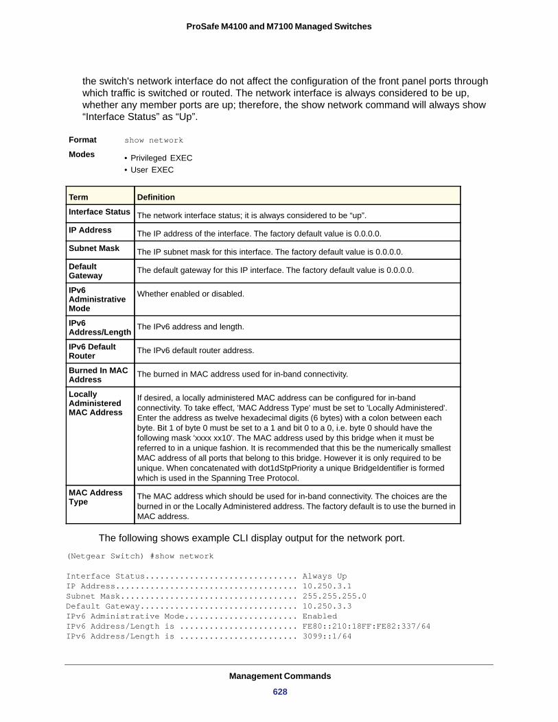
ProSafe M4100 and M7100 Managed Switches
the switch's network interface do not affect the configuration of the front panel ports through which traffic is switched or routed. The network interface is always considered to be up, whether any member ports are up; therefore, the show network command will always show “Interface Status” as “Up”.
Format show network
Modes • Privileged EXEC• User EXEC
Interface Status
IP Address
Subnet Mask
Default Gateway
IPv6 Administrative Mode
IPv6 Address/Length
IPv6 Default Router
Burned In MAC Address
Locally Administered MAC Address
MAC Address Type
The following shows example CLI display output for the network port.
(Netgear Switch) #show network Interface Status............................... Always UpIP Address..................................... 10.250.3.1Subnet Mask.................................... 255.255.255.0Default Gateway................................ 10.250.3.3IPv6 Administrative Mode....................... EnabledIPv6 Address/Length is ........................ FE80::210:18FF:FE82:337/64IPv6 Address/Length is ........................ 3099::1/64
Term Definition
The network interface status; it is always considered to be “up”.
The IP address of the interface. The factory default value is 0.0.0.0.
The IP subnet mask for this interface. The factory default value is 0.0.0.0.
The default gateway for this IP interface. The factory default value is 0.0.0.0.
Whether enabled or disabled.
The IPv6 address and length.
The IPv6 default router address.
The burned in MAC address used for in-band connectivity.
If desired, a locally administered MAC address can be configured for in-band connectivity. To take effect, 'MAC Address Type' must be set to 'Locally Administered'. Enter the address as twelve hexadecimal digits (6 bytes) with a colon between each byte. Bit 1 of byte 0 must be set to a 1 and bit 0 to a 0, i.e. byte 0 should have the following mask 'xxxx xx10'. The MAC address used by this bridge when it must be referred to in a unique fashion. It is recommended that this be the numerically smallest MAC address of all ports that belong to this bridge. However it is only required to be unique. When concatenated with dot1dStpPriority a unique BridgeIdentifier is formed which is used in the Spanning Tree Protocol.
The MAC address which should be used for in-band connectivity. The choices are the burned in or the Locally Administered address. The factory default is to use the burned in MAC address.
Management Commands
628
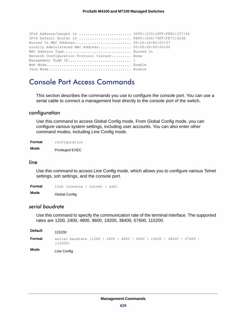
ProSafe M4100 and M7100 Managed Switches
IPv6 Address/Length is ........................ 3099::210:18FF:FE82:337/64IPv6 Default Router is ........................ FE80::204:76FF:FE73:423ABurned In MAC Address.......................... 00:10:18:82:03:37Locally Administered MAC Address............... 00:00:00:00:00:00MAC Address Type............................... Burned InNetwork Configuration Protocol Current......... NoneManagement VLAN ID............................. 1Web Mode....................................... EnableJava Mode...................................... Enable
Console Port Access Commands
This section describes the commands you use to configure the console port. You can use a serial cable to connect a management host directly to the console port of the switch.
configuration
Use this command to access Global Config mode. From Global Config mode, you can configure various system settings, including user accounts. You can also enter other command modes, including Line Config mode.
Format configuration
Mode
line
Use this command to access Line Config mode, which allows you to configure various Telnet settings, ssh settings, and the console port.
Format line {console | telnet | ssh}
Mode
serial baudrate
Use this command to specify the communication rate of the terminal interface. The supported rates are 1200, 2400, 4800, 9600, 19200, 38400, 57600, 115200.
Default
Format serial baudrate {1200 | 2400 | 4800 | 9600 | 19200 | 38400 | 57600 | 115200}
Mode
Privileged EXEC
Global Config
115200
Line Config
Management Commands
629
ProSafe M4100 and M7100 Managed Switches
no serial baudrate
Use this command to set the communication rate of the terminal interface.
Format no serial baudrate
Mode
serial timeout
Use this command to specify the maximum connect time (in minutes) without console activity. A value of 0 indicates that a console can be connected indefinitely. The time range is 0–160.
Default
Format serial timeout <0-160>
Mode
no serial timeout
Use this command to set the maximum connect time (in minutes) without console activity.
Format no serial timeout
Mode
login authentication
Use this command in line configuration mode to specify a login authentication method list for remote telnet or console.
Format login authentication {default | list-name}
Mode
no login authentication
Use this command to return to the default specified by the login authentication command.
Format no login authentication {default | list-name}
Mode
Line Config
5
Line Config
Line Config
Line Config
Line Config
Management Commands
630
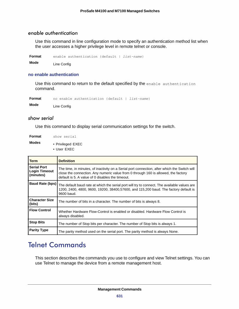
ProSafe M4100 and M7100 Managed Switches
enable authentication
Use this command in line configuration mode to specify an authentication method list when the user accesses a higher privilege level in remote telnet or console.
Format enable authentication {default | list-name}
Mode
no enable authentication
Use this command to return to the default specified by the enable authentication command.
Format no enable authentication {default | list-name}
Mode
show serial
Use this command to display serial communication settings for the switch.
Format show serial
Modes • Privileged EXEC• User EXEC
Serial Port Login Timeout (minutes)
Baud Rate (bps)
Character Size (bits)
Flow Control
Stop Bits
Parity Type
Telnet Commands
This section describes the commands you use to configure and view Telnet settings. You can use Telnet to manage the device from a remote management host.
Line Config
Line Config
Term Definition
The time, in minutes, of inactivity on a Serial port connection, after which the Switch will close the connection. Any numeric value from 0 through 160 is allowed, the factory default is 5. A value of 0 disables the timeout.
The default baud rate at which the serial port will try to connect. The available values are 1200, 2400, 4800, 9600, 19200, 38400,57600, and 115,200 baud. The factory default is 9600 baud.
The number of bits in a character. The number of bits is always 8.
Whether Hardware Flow-Control is enabled or disabled. Hardware Flow Control is always disabled.
The number of Stop bits per character. The number of Stop bits is always 1.
The parity method used on the serial port. The parity method is always None.
Management Commands
631
ProSafe M4100 and M7100 Managed Switches
ip telnet server enable
Use this command to enable Telnet connections to the system and to enable the Telnet Server Admin Mode. This command opens the Telnet listening port.
Default
Format ip telnet server enable
Mode
no ip telnet server enable
Use this command to disable Telnet access to the system and to disable the Telnet Server Admin Mode. This command closes the Telnet listening port and disconnects all open Telnet sessions.
Format no ip telnet server enable
Mode
telnet
Use this command to establish a new outbound Telnet connection to a remote host. The host value must be a valid IP address or host name. Valid values for port should be a valid decimal integer in the range of 0–65,535, where the default value is 23. If [debug] is used, the current Telnet options enabled is displayed. The optional line parameter sets the outbound Telnet operational mode as ‘linemode’ where, by default, the operational mode is ‘character mode’. The noecho option disables local echo.
Format telnet <ip-address|hostname> <port> [debug] [line] [noecho]
Modes • Privileged EXEC• User EXEC
transport input telnet
Use this command to regulate new Telnet sessions. If enabled, new Telnet sessions can be established until there are no more sessions available. An established session remains active until the session is ended or an abnormal network error ends the session.
Note: If the Telnet Server Admin Mode is disabled, Telnet sessions cannot be established. Use the ip telnet server enable command to enable Telnet Server Admin Mode.
enabled
Privileged EXEC
Privileged EXEC
Management Commands
632
ProSafe M4100 and M7100 Managed Switches
no transport input telnet
Use this command to prevent new Telnet sessions from being established.
Format no transport input telnet
Mode
transport output telnet
Use this command to regulate new outbound Telnet connections. If enabled, new outbound Telnet sessions can be established until the system reaches the maximum number of simultaneous outbound Telnet sessions allowed. An established session remains active until the session is ended or an abnormal network error ends it.
Default
Format transport output telnet
Mode
no transport output telnet
Use this command to prevent new outbound Telnet connection from being established.
Format no transport output telnet
Mode
session-limit
Use this command to specify the maximum number of simultaneous outbound Telnet sessions. A value of 0 indicates that no outbound Telnet session can be established.
Default
Format session-limit <0-5>
Mode
Default enabled
Format transport input telnet
Mode Line Config
Line Config
enabled
Line Config
Line Config
5
Line Config
Management Commands
633
ProSafe M4100 and M7100 Managed Switches
no session-limit
Use this command to set the maximum number of simultaneous outbound Telnet sessions to the default value.
Format no session-limit
Mode
session-timeout
Use this command to set the Telnet session timeout value. The timeout value unit of time is minutes.
Default
Format session-timeout <1-160>
Mode
no session-timeout
Use this command to set the Telnet session timeout value to the default. The timeout value unit of time is minutes.
Format no session-timeout
Mode
telnetcon maxsessions
Use this command to specify the maximum number of Telnet connection sessions that can be established. A value of 0 indicates that no Telnet connection can be established. The range is 0-5.
Default
Format telnetcon maxsessions <0-4>
Mode
no telnetcon maxsessions
Use this command to set the maximum number of Telnet connection sessions that can be established to the default value.
Format no telnetcon maxsessions
Mode
Line Config
5
Line Config
Line Config
4
Privileged EXEC
Privileged EXEC
Management Commands
634
ProSafe M4100 and M7100 Managed Switches
telnetcon timeout
Use this command to set the Telnet connection session timeout value, in minutes. A session is active as long as the session has not been idle for the value set. The time is a decimal value from 1 to 160.
Note: When you change the timeout value, the new value is applied to all active and inactive sessions immediately. Any sessions that have been idle longer than the new timeout value are disconnected immediately.
no telnetcon timeout
Use this command to set the Telnet connection session timeout value to the default.
Note: Changing the timeout value for active sessions does not become effective until the session is reaccessed. Also, any keystroke activates the new timeout duration.
show telnet
Use this command to display the current outbound Telnet settings. In other words, these settings apply to Telnet connections initiated from the switch to a remote system.
Format show telnet
Modes • Privileged EXEC• User EXEC
Default 5
Format telnetcon timeout <1-160>
Mode Privileged EXEC
Format no telnetcon timeout
Mode Privileged EXEC
Management Commands
635
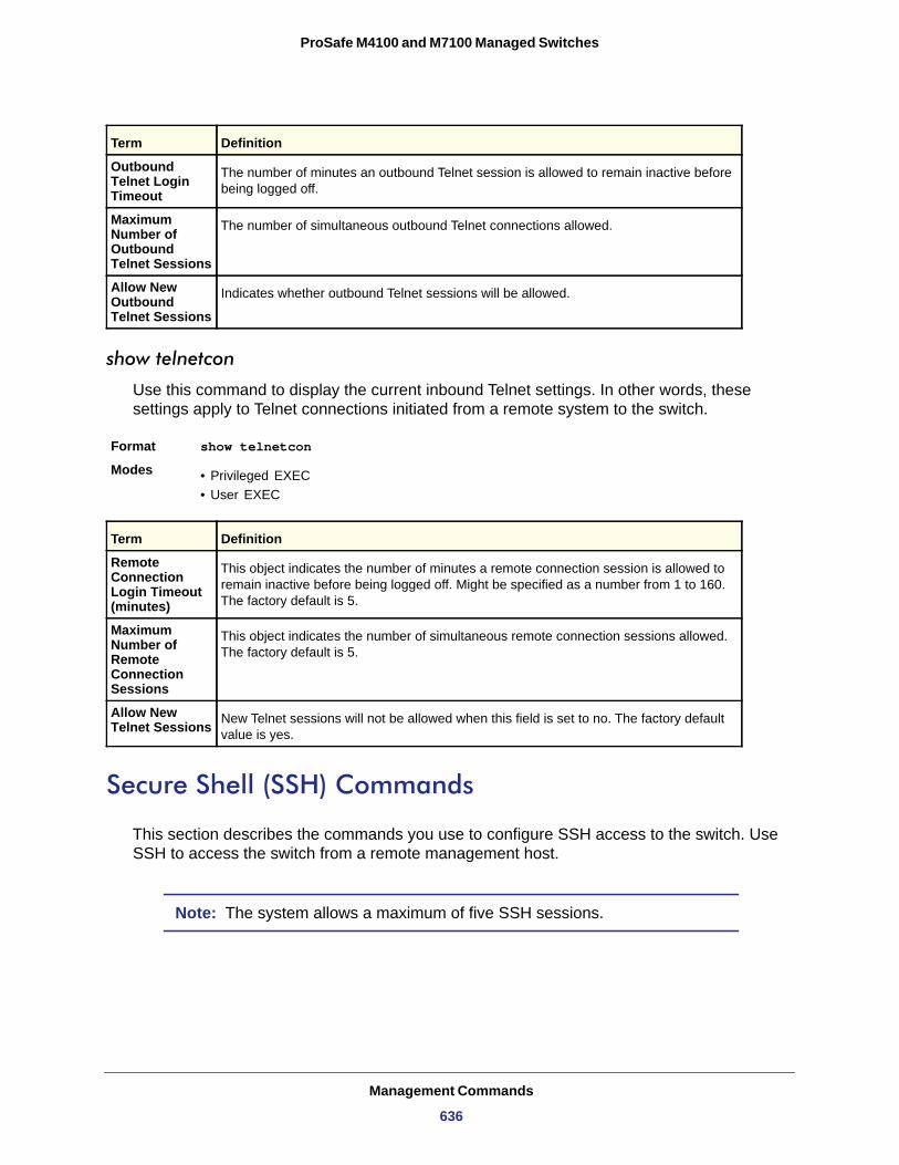
ProSafe M4100 and M7100 Managed Switches
Outbound Telnet Login Timeout
Maximum Number of Outbound Telnet Sessions
Allow New Outbound Telnet Sessions
show telnetcon
Use this command to display the current inbound Telnet settings. In other words, these settings apply to Telnet connections initiated from a remote system to the switch.
Format show telnetcon Modes • Privileged EXEC
• User EXEC
Remote Connection Login Timeout (minutes)
Maximum Number of Remote Connection Sessions
Allow New Telnet Sessions
Secure Shell (SSH) Commands
This section describes the commands you use to configure SSH access to the switch. Use SSH to access the switch from a remote management host.
Note: The system allows a maximum of five SSH sessions.
Term Definition
The number of minutes an outbound Telnet session is allowed to remain inactive before being logged off.
The number of simultaneous outbound Telnet connections allowed.
Indicates whether outbound Telnet sessions will be allowed.
Term Definition
This object indicates the number of minutes a remote connection session is allowed to remain inactive before being logged off. Might be specified as a number from 1 to 160. The factory default is 5.
This object indicates the number of simultaneous remote connection sessions allowed. The factory default is 5.
New Telnet sessions will not be allowed when this field is set to no. The factory default value is yes.
Management Commands
636
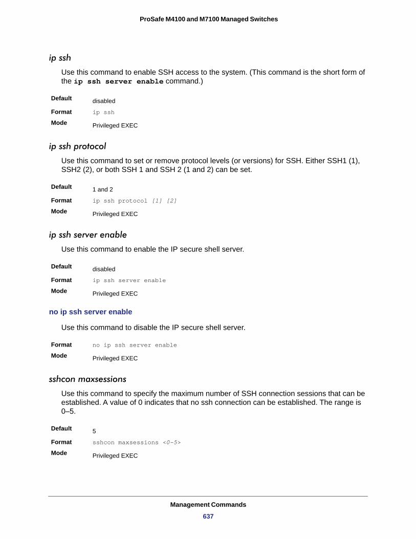
ProSafe M4100 and M7100 Managed Switches
ip ssh
Use this command to enable SSH access to the system. (This command is the short form of the ip ssh server enable command.)
Default
Format ip ssh
Mode
ip ssh protocol
Use this command to set or remove protocol levels (or versions) for SSH. Either SSH1 (1), SSH2 (2), or both SSH 1 and SSH 2 (1 and 2) can be set.
Default
Format ip ssh protocol [1] [2]
Mode
ip ssh server enable
Use this command to enable the IP secure shell server.
Default
Format ip ssh server enable
Mode
no ip ssh server enable
Use this command to disable the IP secure shell server.
Format no ip ssh server enable
Mode
sshcon maxsessions
Use this command to specify the maximum number of SSH connection sessions that can be established. A value of 0 indicates that no ssh connection can be established. The range is 0–5.
Default
Format sshcon maxsessions <0-5>
Mode
disabled
Privileged EXEC
1 and 2
Privileged EXEC
disabled
Privileged EXEC
Privileged EXEC
5
Privileged EXEC
Management Commands
637
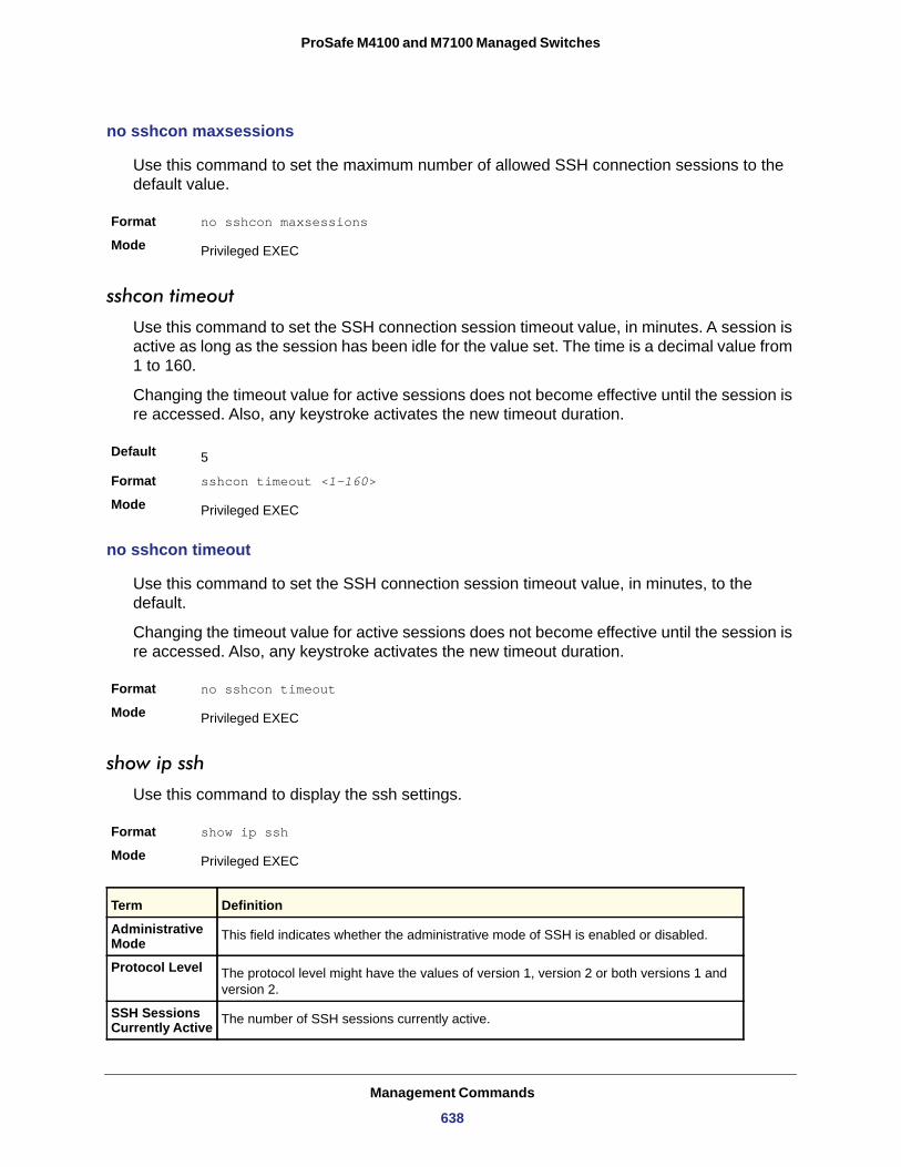
ProSafe M4100 and M7100 Managed Switches
no sshcon maxsessions
Use this command to set the maximum number of allowed SSH connection sessions to the default value.
Format no sshcon maxsessions
Mode
sshcon timeout
Use this command to set the SSH connection session timeout value, in minutes. A session is active as long as the session has been idle for the value set. The time is a decimal value from 1 to 160.
Changing the timeout value for active sessions does not become effective until the session is re accessed. Also, any keystroke activates the new timeout duration.
Default
Format sshcon timeout <1-160>
Mode
no sshcon timeout
Use this command to set the SSH connection session timeout value, in minutes, to the default.
Changing the timeout value for active sessions does not become effective until the session is re accessed. Also, any keystroke activates the new timeout duration.
Format no sshcon timeout
Mode
show ip ssh
Use this command to display the ssh settings.
Format show ip ssh
Mode
Privileged EXEC
5
Privileged EXEC
Privileged EXEC
Privileged EXEC
Term Definition
Administrative Mode This field indicates whether the administrative mode of SSH is enabled or disabled.
Protocol Level The protocol level might have the values of version 1, version 2 or both versions 1 and version 2.
SSH Sessions Currently Active The number of SSH sessions currently active.
Management Commands
638
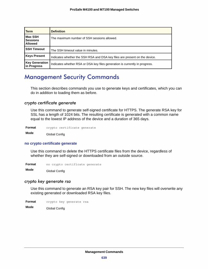
ProSafe M4100 and M7100 Managed Switches
Management Security Commands
This section describes commands you use to generate keys and certificates, which you can do in addition to loading them as before.
crypto certificate generate
Use this command to generate self-signed certificate for HTTPS. The generate RSA key for SSL has a length of 1024 bits. The resulting certificate is generated with a common name equal to the lowest IP address of the device and a duration of 365 days.
Format crypto certificate generate
Mode
no crypto certificate generate
Use this command to delete the HTTPS certificate files from the device, regardless of whether they are self-signed or downloaded from an outside source.
Format no crypto certificate generate
Mode
crypto key generate rsa
Use this command to generate an RSA key pair for SSH. The new key files will overwrite any existing generated or downloaded RSA key files.
Format crypto key generate rsa
Mode
Max SSH Sessions Allowed
The maximum number of SSH sessions allowed.
SSH Timeout The SSH timeout value in minutes.
Keys Present Indicates whether the SSH RSA and DSA key files are present on the device.
Key Generation in Progress Indicates whether RSA or DSA key files generation is currently in progress.
Global Config
Global Config
Global Config
Term Definition
Management Commands
639
ProSafe M4100 and M7100 Managed Switches
no crypto key generate rsa
Use this command to delete the RSA key files from the device.
Format no crypto key generate rsa
Mode
crypto key generate dsa
Use this command to generate a DSA key pair for SSH. The new key files will overwrite any existing generated or downloaded DSA key files.
Format crypto key generate dsa
Mode
no crypto key generate dsa
Use this command to delete the DSA key files from the device.
Format no crypto key generate dsa
Mode
Hypertext Transfer Protocol (HTTP) Commands
This section describes the commands you use to configure HTTP and secure HTTP access to the switch. Access to the switch by using a Web browser is enabled by default. Everything you can view and configure by using the CLI is also available by using the Web.
ip http server
Use this command to enable access to the switch through the Web interface. When access is enabled, the user can login to the switch from the Web interface. When access is disabled, the user cannot login to the switch's Web server. Disabling the Web interface takes effect immediately. All interfaces are affected.
Default
Format ip http server
Mode
Global Config
Global Config
Global Config
enabled
Privileged EXEC
Management Commands
640
ProSafe M4100 and M7100 Managed Switches
no ip http server
Use this command to disable access to the switch through the Web interface. When access is disabled, the user cannot login to the switch's Web server.
Format no ip http server
Mode
ip http secure-server
Use this command to enable the secure socket layer for secure HTTP.
Default
Format ip http secure-server
Mode
no ip http secure-server
Use this command to disable the secure socket layer for secure HTTP.
Format no ip http secure-server
Mode
ip http java
Use this command to enable the Web Java mode. The Java mode applies to both secure and unsecure web connections.
Format ip http java
Mode
no ip http java
Use this command to disable the Web Java mode. The Java mode applies to both secure and unsecure web connections.
Format no ip http java
Mode
ip http session hard-timeout
Use this command to configure the hard timeout for un-secure HTTP sessions in hours. Configuring this value to zero will give an infinite hard-timeout. When this timeout expires, the
Privileged EXEC
disabled
Privileged EXEC
Privileged EXEC
Default Enabled
Privileged EXEC
Privileged EXEC
Management Commands
641
ProSafe M4100 and M7100 Managed Switches
user will be forced to reauthenticate. This timer begins on initiation of the web session and is unaffected by the activity level of the connection.
Format ip http session hard-timeout <0-168>
Mode
no ip http session hard-timeout
Use this command to restore the hard timeout for unsecure HTTP sessions to the default value.
Format no ip http session hard-timeout
Mode
ip http authentication
Use this command to specify the authentication methods for http server users. The additional methods of authentication are used only if the previous method returns an error, not if it fails. To ensure that the authentication succeeds even if all methods return an error, specify none as the final method in the command line. For example If none specified as an authentication method after radius, no authentication is used if the radius server is down.
Format ip http authentication method1 [method2 ...]
Mode
Local
Radius
Tacacs
None
no ip http authentication
Use this command to restore the authentication methods to the default.
Format no ip http authentication method1 [method2 ...]
Mode
Default 24
Privileged EXEC
Privileged EXEC
Global ConfigC
Term Definition
Uses the local username database for authentication.
Uses the list of all RADIUS servers for authentication.
Uses the list of all TACACS servers for authentication.
Uses no authentication.
Global Config
Management Commands
642
ProSafe M4100 and M7100 Managed Switches
ip http session maxsessions
Use this command to limit the number of allowable unsecure HTTP sessions. Zero is the configurable minimum.
Format ip http session maxsessions <0-16>
Mode
no ip http session maxsessions
Use this command to restore the number of allowable unsecure HTTP sessions to the default value.
Format no ip http session maxsessions
Mode
ip http session soft-timeout
Use this command to configure the soft timeout for unsecure HTTP sessions in minutes. Configuring this value to zero will give an infinite soft-timeout. When this timeout expires the user will be forced to reauthenticate. This timer begins on initiation of the Web session and is restarted with each access to the switch.
Format ip http session soft-timeout <0-60>
Mode
no ip http session soft-timeout
Use this command to reset the soft timeout for unsecure HTTP sessions to the default value.
Format no ip http session soft-timeout
Mode
ip http secure-session maxsessions
Use this command to limit the number of secure HTTP sessions. Zero is the configurable minimum.
Format ip http secure-session maxsessions <0-16>
Mode
Default 16
Privileged EXEC
Privileged EXEC
Default 5
Privileged EXEC
Privileged EXEC
Default 16
Privileged EXEC
Management Commands
643
ProSafe M4100 and M7100 Managed Switches
no ip http secure-session maxsessions
Use this command to restore the number of allowable secure HTTP sessions to the default value.
Format no ip http secure-session maxsessions
Mode
ip http secure-session soft-timeout
Use this command to configure the soft timeout for secure HTTP sessions in minutes. Configuring this value to zero will give an infinite soft-timeout. When this timeout expires, you are forced to reauthenticate. This timer begins on initiation of the Web session and is restarted with each access to the switch. The secure-session soft-timeout cannot be set to zero (infinite).
Default
Format ip http secure-session soft-timeout <1-60>
Mode
no ip http secure-session soft-timeout
Use this command to restore the soft timeout for secure HTTP sessions to the default value.
Format no ip http secure-session soft-timeout
Mode
ip http secure-session hard-timeout
Use this command to configure the hard timeout for secure HTTP sessions in hours. When the timeout expires, the user is forced to reauthenticate. This timer begins on initiation of the Web session and is unaffected by the activity level of the connection. The secure-session hard-timeout cannot be set to zero (infinite).
Format ip http secure-session hard-timeout <1-168>
Mode
no ip http secure-session hard-timeout
Use this command to reset the hard timeout for secure HTTP sessions to the default value.
Format no ip http secure-session hard-timeout
Mode
Privileged EXEC
5
Privileged EXEC
Privileged EXEC
Default 24
Privileged EXEC
Privileged EXEC
Management Commands
644
ProSafe M4100 and M7100 Managed Switches
ip https authentication
Use this command to specify the authentication methods for http server users. The additional methods of authentication are used only if the previous method returns an error, not if it fails. To ensure that the authentication succeeds even if all methods return an error, specify none as the final method in the command line. If none is specified as an authentication method after radius, no authentication is used if the radius server is down.
Format ip https authentication method1 [method2 ...]
Mode
Local
Radius
Tacacs
None
no ip https authentication
Use this command to restore the authentication methods to the default for http server users.
Format no ip https authentication method1 [method2 ...]
Mode
ip http secure-port
Use this command to set the SSL port where port can be 1-65535 and the default is port 443.
Default
Format ip http secure-port <portid>
Mode
no ip http secure-port
Use this command to reset the SSL port to the default value.
Format no ip http secure-port
Mode
Global ConfigC
Term Definition
Uses the local username database for authentication.
Uses the list of all RADIUS servers for authentication.
Uses the list of all TACACS servers for authentication.
Uses no authentication.
Global Config
443
Privileged EXEC
Privileged EXEC
Management Commands
645
ProSafe M4100 and M7100 Managed Switches
ip http secure-protocol
Use this command to set protocol levels (versions). The protocol level can be set to TLS1, SSL3 or to both TLS1 and SSL3.
Default
Format ip http secure-protocol [SSL3] [TLS1]
Mode
show ip http
Use this command to display the http settings for the switch.
Format show ip http
Mode
HTTP Mode (Unsecure)
Java Mode
Maximum Allowable HTTP Sessions
HTTP Session Hard Timeout
HTTP Session Soft Timeout
HTTP Mode (Secure)
Secure Port
Secure Protocol Level(s)
Maximum Allowable HTTPS Sessions
HTTPS Session Hard Timeout
HTTPS Session Soft Timeout
Certificate Present
Certificate Generation in Progress
SSL3 and TLS1
Privileged EXEC
Privileged EXEC
Term Definition
The unsecure HTTP server administrative mode.
The java applet administrative mode which applies to both secure and unsecure web connections.
The number of allowable unsecure http sessions.
The hard timeout for unsecure http sessions in hours.
The soft timeout for unsecure http sessions in minutes.
The secure HTTP server administrative mode.
The secure HTTP server port number.
The protocol level might have the values of SSL3, TSL1, or both SSL3 and TSL1.
The number of allowable secure http sessions.
The hard timeout for secure http sessions in hours.
The soft timeout for secure http sessions in minutes.
Indicates whether the secure-server certificate files are present on the device.
Indicates whether certificate generation is currently in progress.
Management Commands
646
ProSafe M4100 and M7100 Managed Switches
Access Commands
Use the commands in this section to close remote connections or to view information about connections to the system.
disconnect
Use the disconnect command to close HTTP, HTTPS, Telnet, or SSH sessions. Use all to close all active sessions, or use <session-id> to specify the session ID to close. To view the possible values for <session-id>, use the show loginsession command.
Format disconnect {<session_id> | all}
Mode
show loginsession
Use this command to display current Telnet and serial port connections to the switch.
Format show loginsession Mode
ID
User Name
Connection From
Idle Time
Session Time
Session Type
User Account Commands
This section describes the commands you use to add, manage, and delete system users. The 7000 series software has two default users: admin and guest. The admin user can view and configure system settings, and the guest user can view settings.
Note: You cannot delete the admin user. There is only one user allowed with read/write privileges. You can configure up to five read-only users on the system.
Privileged EXEC
Privileged EXEC
Term Definition
Login Session ID.
The name the user entered to log on to the system.
IP address of the remote client machine or EIA-232 for the serial port connection.
Time this session has been idle.
Total time this session has been connected.
Shows the type of session, which can be HTTP, HTTPS, telnet, serial, or SSH.
Management Commands
647
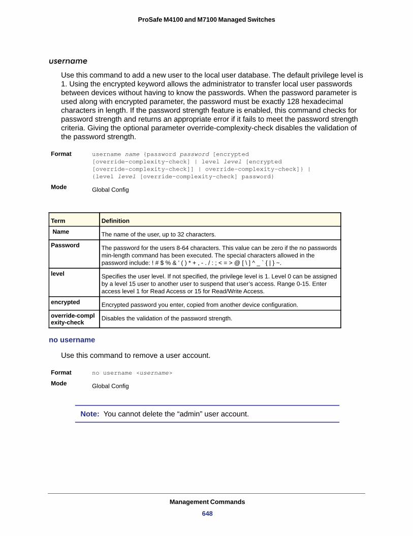
ProSafe M4100 and M7100 Managed Switches
username
Use this command to add a new user to the local user database. The default privilege level is 1. Using the encrypted keyword allows the administrator to transfer local user passwords between devices without having to know the passwords. When the password parameter is used along with encrypted parameter, the password must be exactly 128 hexadecimal characters in length. If the password strength feature is enabled, this command checks for password strength and returns an appropriate error if it fails to meet the password strength criteria. Giving the optional parameter override-complexity-check disables the validation of the password strength.
Format username name {password password [encrypted [override-complexity-check] | level level [encrypted [override-complexity-check]] | override-complexity-check]} | {level level [override-complexity-check] password}
Mode
no username
Use this command to remove a user account.
Format no username <username>
Mode
Note: You cannot delete the “admin” user account.
Global Config
Term Definition
Name The name of the user, up to 32 characters.
Password The password for the users 8-64 characters. This value can be zero if the no passwords min-length command has been executed. The special characters allowed in the password include: ! # $ % & ' ( ) * + , - . / : ; < = > @ [ \ ] ^ _ ` { | } ~.
level Specifies the user level. If not specified, the privilege level is 1. Level 0 can be assigned by a level 15 user to another user to suspend that user’s access. Range 0-15. Enter access level 1 for Read Access or 15 for Read/Write Access.
encrypted Encrypted password you enter, copied from another device configuration.
override-complexity-check Disables the validation of the password strength.
Global Config
Management Commands
648
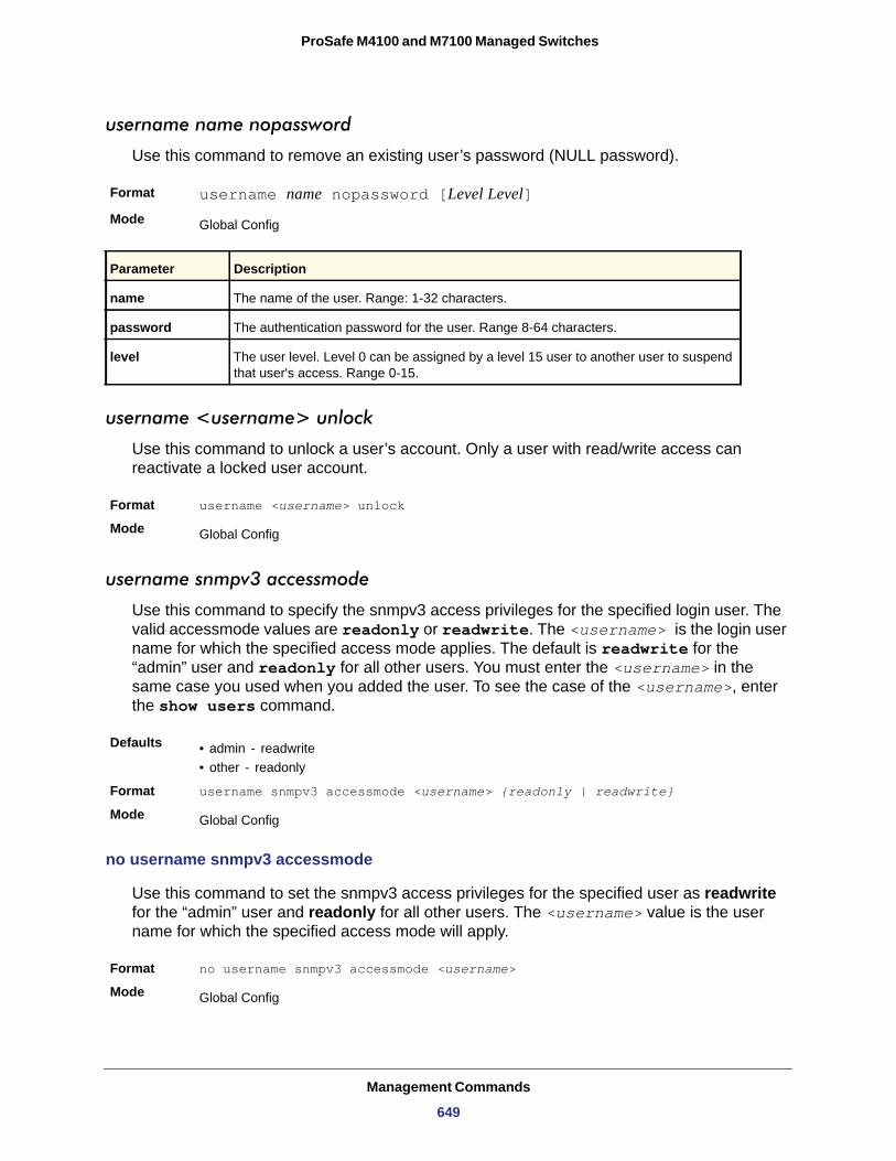
ProSafe M4100 and M7100 Managed Switches
username name nopassword
Use this command to remove an existing user’s password (NULL password).
Format username name nopassword [Level Level]Mode
username <username> unlock
Use this command to unlock a user’s account. Only a user with read/write access can reactivate a locked user account.
Format username <username> unlock
Mode
username snmpv3 accessmode
Use this command to specify the snmpv3 access privileges for the specified login user. The valid accessmode values are readonly or readwrite. The <username> is the login user name for which the specified access mode applies. The default is readwrite for the “admin” user and readonly for all other users. You must enter the <username> in the same case you used when you added the user. To see the case of the <username>, enter the show users command.
Defaults • admin - readwrite• other - readonly
Format username snmpv3 accessmode <username> {readonly | readwrite}
Mode
no username snmpv3 accessmode
Use this command to set the snmpv3 access privileges for the specified user as readwrite for the “admin” user and readonly for all other users. The <username> value is the user name for which the specified access mode will apply.
Format no username snmpv3 accessmode <username>
Mode
Global Config
Parameter Description
name The name of the user. Range: 1-32 characters.
password The authentication password for the user. Range 8-64 characters.
level The user level. Level 0 can be assigned by a level 15 user to another user to suspend that user's access. Range 0-15.
Global Config
Global Config
Global Config
Management Commands
649
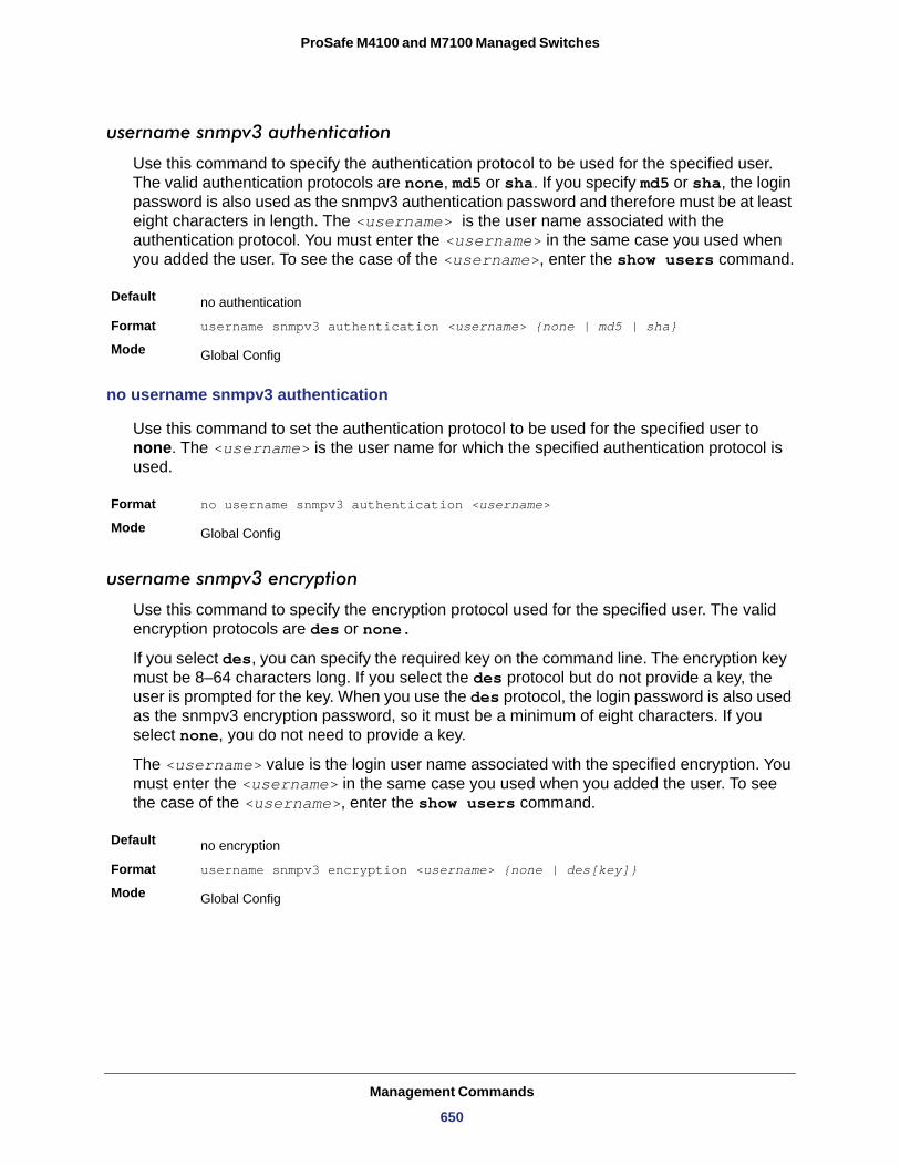
ProSafe M4100 and M7100 Managed Switches
username snmpv3 authentication
Use this command to specify the authentication protocol to be used for the specified user. The valid authentication protocols are none, md5 or sha. If you specify md5 or sha, the login password is also used as the snmpv3 authentication password and therefore must be at least eight characters in length. The <username> is the user name associated with the authentication protocol. You must enter the <username> in the same case you used when you added the user. To see the case of the <username>, enter the show users command.
Default
Format username snmpv3 authentication <username> {none | md5 | sha}
Mode
no username snmpv3 authentication
Use this command to set the authentication protocol to be used for the specified user to none. The <username> is the user name for which the specified authentication protocol is used.
Format no username snmpv3 authentication <username>
Mode
username snmpv3 encryption
Use this command to specify the encryption protocol used for the specified user. The valid encryption protocols are des or none.
If you select des, you can specify the required key on the command line. The encryption key must be 8–64 characters long. If you select the des protocol but do not provide a key, the user is prompted for the key. When you use the des protocol, the login password is also used as the snmpv3 encryption password, so it must be a minimum of eight characters. If you select none, you do not need to provide a key.
The <username> value is the login user name associated with the specified encryption. You must enter the <username> in the same case you used when you added the user. To see the case of the <username>, enter the show users command.
Default
Format username snmpv3 encryption <username> {none | des[key]}
Mode
no authentication
Global Config
Global Config
no encryption
Global Config
Management Commands
650
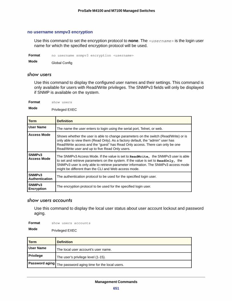
ProSafe M4100 and M7100 Managed Switches
no username snmpv3 encryption
Use this command to set the encryption protocol to none. The <username> is the login user name for which the specified encryption protocol will be used.
Format no username snmpv3 encryption <username>
Mode
show users
Use this command to display the configured user names and their settings. This command is only available for users with Read/Write privileges. The SNMPv3 fields will only be displayed if SNMP is available on the system.
Format show users
Mode
User Name
Access Mode
SNMPv3 Access Mode
SNMPv3 Authentication
SNMPv3 Encryption
show users accounts
Use this command to display the local user status about user account lockout and password aging.
Format show users accounts
Mode
Global Config
Privileged EXEC
Term Definition
The name the user enters to login using the serial port, Telnet, or web.
Shows whether the user is able to change parameters on the switch (Read/Write) or is only able to view them (Read Only). As a factory default, the “admin” user has Read/Write access and the “guest” has Read Only access. There can only be one Read/Write user and up to five Read Only users.
The SNMPv3 Access Mode. If the value is set to ReadWrite, the SNMPv3 user is able to set and retrieve parameters on the system. If the value is set to ReadOnly, the SNMPv3 user is only able to retrieve parameter information. The SNMPv3 access mode might be different than the CLI and Web access mode.
The authentication protocol to be used for the specified login user.
The encryption protocol to be used for the specified login user.
Privileged EXEC
Term Definition
User Name The local user account’s user name.
Privilege The user’s privilege level (1-15).
Password aging The password aging time for the local users.
Management Commands
651
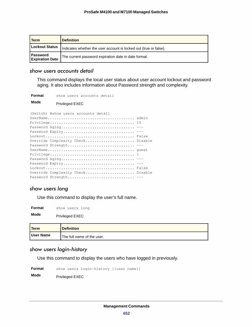
ProSafe M4100 and M7100 Managed Switches
show users accounts detail
This command displays the local user status about user account lockout and password aging. It also includes information about Password strength and complexity.
Format show users accounts detail
Mode
(Switch) #show users accounts detailUserName....................................... adminPrivilege...................................... 15Password Aging................................. ---Password Expiry................................ ---Lockout........................................ FalseOverride Complexity Check...................... DisablePassword Strength.............................. ---UserName....................................... guestPrivilege...................................... 1Password Aging................................. ---Password Expiry................................ ---Lockout........................................ FalseOverride Complexity Check...................... DisablePassword Strength.............................. ---
show users long
Format show users long
Mode
Use this command to display the user’s full name.
User Name
show users login-history
Use this command to display the users who have logged in previously.
Format show users login-history [{user name}]
Mode
Lockout Status Indicates whether the user account is locked out (true or false).
Password Expiration Date The current password expiration date in date format.
Privileged EXEC
Privileged EXEC
Term Definition
The full name of the user.
Privileged EXEC
Term Definition
Management Commands
652
ProSafe M4100 and M7100 Managed Switches
Login Time
Username
Protocol
Location
passwords min-length
Use this command to enforce a minimum password length for local users. The value also applies to the enable password. The valid range is 0–64.
Default
Format passwords min-length <0-64>
Mode
no passwords min-length
Use this command to set the minimum password length to the default value.
Format no passwords min-length
Mode
passwords history
Use this command to set the number of previous passwords that shall be stored for each user account. When a local user changes his or her password, the user will not be able to reuse any password stored in password history. This ensures that users do not reuse their passwords often. The valid range is 0-10.
Default
Format passwords history <0-10>
Mode
no passwords history
Use this command to set the password history to the default value.
Format no passwords history
Mode
Term Definition
The time at which the user logged in.
The user name used to login.
The protocol that the user used to login.
The location of the user.
8
Global Config
Global Config
0
Global Config
Global Config
Management Commands
653
ProSafe M4100 and M7100 Managed Switches
passwords aging
Use this command to implement aging on passwords for local users. When a user’s password expires, the user will be prompted to change it before logging in again. The valid range is 1-365. The default is 0, or no aging.
Default
Format passwords aging <1-365>
Mode
no passwords aging
Use this command to set the password aging to the default value.
Format no passwords aging
Mode
passwords lock-out
Use this command to strengthen the security of the switch by locking user accounts that have failed login due to wrong passwords. When a lockout count is configured, a user that is logged in must enter the correct password within that count. Otherwise the user will be locked out from further switch access. Only a user with read/write access can reactivate a locked user account. Password lockout does not apply to logins from the serial console. The valid range is 1-5. The default is 0, or no lockout count enforced.
Format passwords lock-out <1-5>
Mode
Default
no passwords lock-out
Use this command to set the password lock-out count to the default value.
Format no passwords lock-out
Mode
passwords strength-check
Use this command to enable the password strength feature. It is used to verify the strength of a password during configuration.
0
Global Config
Global Config
Global Config
0
Global Config
Format passwords strength-check
Management Commands
654
ProSafe M4100 and M7100 Managed Switches
no passwords strength-check
Use this command to disable the password strength-check.
Format no passwords strength-check
Mode
passwords strength minimum uppercase-letters
Use this command to enforce a minimum number of uppercase letters that a password should contain. The valid range is 0-16. The default is 2. Minimum of 0 means no restriction on that set of characters.
Format passwords strength minimum uppercase-letters
Mode
Default
no passwords strength minimum uppercase-letters
Use this command to reset the minimum number of uppercase letters to the default value.
Format no passwords strength minimum uppercase-characters
Mode
passwords strength minimum lowercase-letters
Use this command to enforce a minimum number of lowercase letters that a password should contain. The valid range is 0-16. The default is 2. Minimum of 0 means no restriction on that set of characters.
Format passwords strength minimum lowercase-letters
Mode
Default
no passwords strength minimum lowercase-letters
Use this command to reset the minimum number of lowercase letters to the default value.
Format no passwords strength minimum lowercase-characters
Mode
Mode Global Config
Default Disable
Global Config
Global Config
2
Global Config
Global Config
2
Global Config
Management Commands
655
ProSafe M4100 and M7100 Managed Switches
passwords strength minimum numeric-characters
Use this command to enforce a minimum number of numeric characters that a password should contain. The valid range is 0-16. The default is 2. Minimum of 0 means no restriction on that set of characters.
Format passwords strength minimum numeric-letters
Mode
Default
no passwords strength minimum numeric-characters
Use this command to reset the minimum number of numeric characters to the default value.
Format no passwords strength minimum numeric-characters
Mode
passwords strength minimum special-characters
Use this command to enforce a minimum number of special characters that a password should contain. The valid range is 0-16. The default is 2. Minimum of 0 means no restriction on that set of characters.
Format passwords strength minimum special-letters
Mode
Default
no passwords strength minimum special-letters
Use this command to reset the minimum number of special letters to the default value.
Format no passwords strength minimum special-letters
Mode
passwords strength maximum consecutive-characters
Use this command to enforce a maximum number of consecutive characters that a password should contain. An example of consecutive characters is abcd. The valid range is 0-16. If a password has consecutive characters more than the configured limit, it fails to configure. The default is 0. A maximum of 0 means no restriction on that set of characters.
Format passwords strength maximum consecutive-characters
Mode
Default
Global Config
2
Global Config
Global Config
2
Global Config
Global Config
0
Management Commands
656
ProSafe M4100 and M7100 Managed Switches
no passwords strength maximum consecutive-characters
Use this command to reset the maximum number of consecutive characters to the default value.
Format no passwords strength maximum consecutive-characters
Mode
passwords strength maximum repeated-characters
Use this command to enforce a maximum number of repeated characters that a password should contain. An example of repeated characters is aaaa. The valid range is 0-16. If a password has a repetition of characters more than the configured limit, it fails to configure. The default is 0. A maximum of 0 means no restriction on that set of characters.
Format passwords strength maximum repeated-characters
Mode
Default
no passwords strength maximum repeated-characters
Use this command to reset the maximum number of repeated-characters to the default value.
Format no passwords strength maximum repeated-characters
Mode
passwords strength minimum character-classes
Use this command to enforce a minimum number of characters classes that a password should contain. Character classes are uppercase letters, lowercase letters, numeric characters, and special characters. The valid range is 0-4. The default is 4.
Format passwords strength minimum character-classes
Mode
Default
no passwords strength minimum character-classes
Use this command to reset the minimum number of character classes to the default value.
Format no passwords strength minimum character-classes
Mode
Global Config
Global Config
0
Global Config
Global Config
4
Global Config
Management Commands
657
ProSafe M4100 and M7100 Managed Switches
passwords strength exclude-keyword
Use this command to exclude the specified keyword while configuring the password. The password does not accept the keyword in any form (in between the string, case insensitive and reverse) as a substring. User can configure up to a maximum of 3 keywords.
Format passwords strength exclude-keyword keyword
Mode
no passwords strength exclude-keyword
Use this command to remove the exclude-keyword.
Format no passwords strength exclude-keyword
Mode
show passwords configuration
Use this command to display the configured password management settings.
Format show passwords configuration
Mode
Global Config
Global Config
Privileged EXEC
Termd Definition
Minimum Password Length Minimum number of characters required when changing passwords.
Password History Number of passwords to store for reuse prevention.
Password Aging Length in days that a password is valid.
Lockout Attempts Number of failed password login attempts before lockout.
Minimum Password Uppercase Letters Minimum number of uppercase characters required when configuring passwords.
Minimum Password Lowercase Letters Minimum number of lowercase characters required when configuring passwords.
Minimum Password Numeric Characters Minimum number of numeric characters required when configuring passwords.
Maximum Password Consecutive Characters
Maximum number of consecutive characters required that the password should contain when configuring passwords.
Maximum Password Repeated Characters Maximum number of repetitions of characters that the password should contain
when configuring passwords.
Management Commands
658
ProSafe M4100 and M7100 Managed Switches
show passwords result
Use this command to display the last password set result information.
Format show passwords result
Mode
Last User Whose Password Is Set
Password Strength Check
Last Password Set Result
aaa authentication login
Use this command to set authentication at login. The default and optional list names that you create with the aaa authentication login command are used with the login authentication command. Create a list by entering the aaa authentication login list-name method command for a particular protocol, where list-name is any character string used to name this list. The method argument identifies the list of methods that the authentication algorithm tries, in the given sequence. The additional methods of authentication are used only if the previous method returns an error, not if it fails.
An example of a method that returns an error is if a RADIUS server is not present, and an example of a method failing is when a RADIUS server cannot authenticate the client. If ‘local’ method is listed first, since local authentication is always available, it only has the fail condition, not error. As such, if ‘local’ method is the first in the list, no other method will be tried.
To ensure that the authentication succeeds even if all methods return an error, specify none as the final method in the command line. For example if none is specified as an authentication method after radius, no authentication is used if the radius server is down.
Format aaa authentication login {default | list-name} method1 [method2...]
Mode
Default Uses the listed authentication methods that follow this argument as the default list of methods when a user logs in.
Minimum Password Character Classes Minimum number of character classes (uppercase, lowercase, numeric, and
special) required when configuring passwords.
Password Exclude- Keywords The set of keywords to be excluded from the configured password when strength
checking is enabled.
Privileged EXEC
Term Definition
Shows the name of the user with the most recently set password.
Shows whether password strength checking is enabled.
Shows whether the attempt to set a password was successful. If the attempt failed, the reason for the failure is included.
Global Config
Termd Definition
Management Commands
659
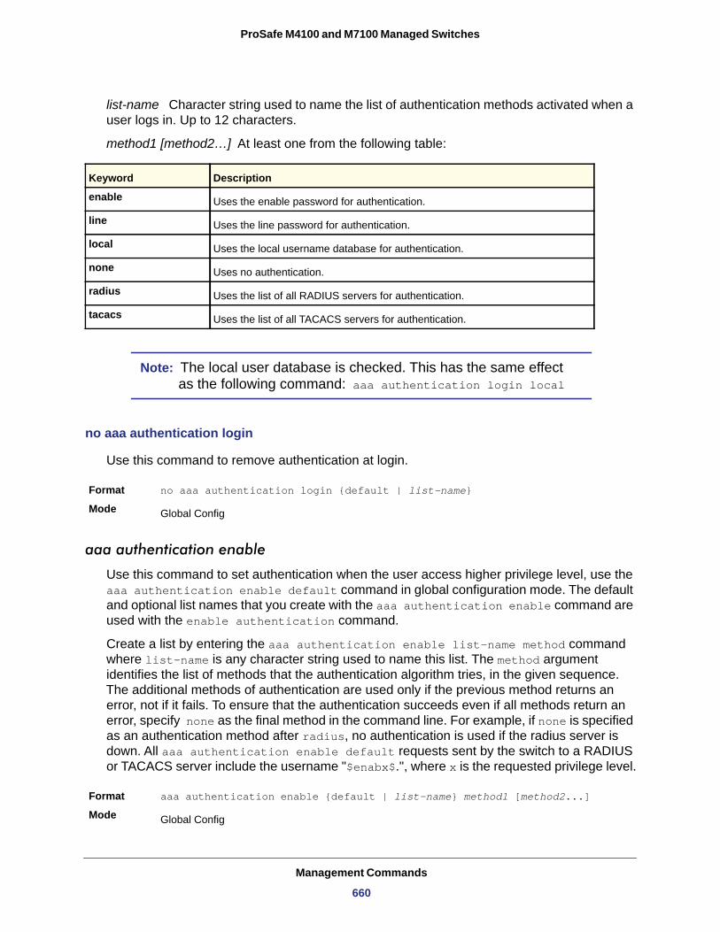
ProSafe M4100 and M7100 Managed Switches
list-name Character string used to name the list of authentication methods activated when a user logs in. Up to 12 characters.
method1 [method2…] At least one from the following table:
enable
line
local
none
radius
tacacs
Note: The local user database is checked. This has the same effect as the following command: aaa authentication login local
no aaa authentication login
Use this command to remove authentication at login.
Format no aaa authentication login {default | list-name}
Mode
aaa authentication enable
Use this command to set authentication when the user access higher privilege level, use the aaa authentication enable default command in global configuration mode. The default and optional list names that you create with the aaa authentication enable command are used with the enable authentication command.
Create a list by entering the aaa authentication enable list-name method command where list-name is any character string used to name this list. The method argument identifies the list of methods that the authentication algorithm tries, in the given sequence. The additional methods of authentication are used only if the previous method returns an error, not if it fails. To ensure that the authentication succeeds even if all methods return an error, specify none as the final method in the command line. For example, if none is specified as an authentication method after radius, no authentication is used if the radius server is down. All aaa authentication enable default requests sent by the switch to a RADIUS or TACACS server include the username "$enabx$.", where x is the requested privilege level.
Format aaa authentication enable {default | list-name} method1 [method2...]
Mode
Keyword Description
Uses the enable password for authentication.
Uses the line password for authentication.
Uses the local username database for authentication.
Uses no authentication.
Uses the list of all RADIUS servers for authentication.
Uses the list of all TACACS servers for authentication.
Global Config
Global Config
Management Commands
660
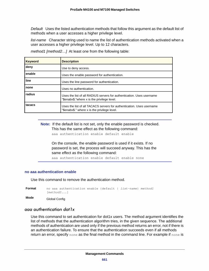
ProSafe M4100 and M7100 Managed Switches
Default Uses the listed authentication methods that follow this argument as the default list of methods when a user accesses a higher privilege level.
list-name Character string used to name the list of authentication methods activated when a user accesses a higher privilege level. Up to 12 characters.
method1 [method2…] At least one from the following table:
deny
enable
line
none
radius
tacacs
Note: If the default list is not set, only the enable password is checked. This has the same effect as the following command: aaa authentication enable default enable On the console, the enable password is used if it exists. If no password is set, the process will succeed anyway. This has the same effect as the following command: aaa authentication enable default enable none
no aaa authentication enable
Use this command to remove the authentication method.
Format no aaa authentication enable {default | list-name} method1 [method2...]
Mode
aaa authentication dot1x
Use this command to set authentication for dot1x users. The method argument identifies the list of methods that the authentication algorithm tries, in the given sequence. The additional methods of authentication are used only if the previous method returns an error, not if there is an authentication failure. To ensure that the authentication succeeds even if all methods return an error, specify none as the final method in the command line. For example if none is
Keyword Description
Use to deny access.
Uses the enable password for authentication.
Uses the line password for authentication.
Uses no authentication.
Uses the list of all RADIUS servers for authentication. Uses username "$enabx$."where x is the privilege level.
Uses the list of all TACACS servers for authentication. Uses username "$enabx$." where x is the privilege level.
Global Config
Management Commands
661
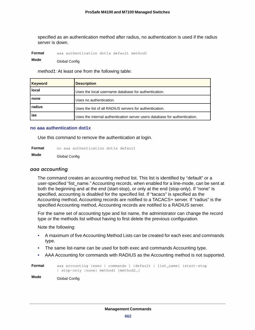
ProSafe M4100 and M7100 Managed Switches
specified as an authentication method after radius, no authentication is used if the radius server is down.
Format aaa authentication dot1x default method1
Mode
method1: At least one from the following table:
local
none
radius
ias
no aaa authentication dot1x
Use this command to remove the authentication at login.
Format no aaa authentication dot1x default
Mode
aaa accounting
The command creates an accounting method list. This list is identified by “default” or a user-specified “list_name.” Accounting records, when enabled for a line-mode, can be sent at both the beginning and at the end (start-stop), or only at the end (stop-only). If “none” is specified, accounting is disabled for the specified list. If “tacacs” is specified as the Accounting method, Accounting records are notified to a TACACS+ server. If “radius” is the specified Accounting method, Accounting records are notified to a RADIUS server.
For the same set of accounting type and list name, the administrator can change the record type or the methods list without having to first delete the previous configuration.
Note the following:
• A maximum of five Accounting Method Lists can be created for each exec and commands type.
• The same list-name can be used for both exec and commands Accounting type.• AAA Accounting for commands with RADIUS as the Accounting method is not supported.
Format aaa accounting {exec | commands } {default | list_name} {start-stop | stop-only |none} method1 [method2…]
Mode
Global Config
Keyword Description
Uses the local username database for authentication.
Uses no authentication.
Uses the list of all RADIUS servers for authentication.
Uses the internal authentication server users database for authentication.
Global Config
Global Config
Management Commands
662
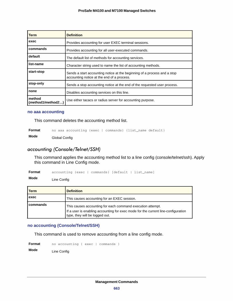
ProSafe M4100 and M7100 Managed Switches
exec
commands
default
list-name
start-stop
stop-only
none
method (method1/method2…)
no aaa accounting
This command deletes the accounting method list.
Format no aaa accounting {exec | commands} {list_name default}
Mode
accounting (Console/Telnet/SSH)
This command applies the accounting method list to a line config (console/telnet/ssh). Apply this command in Line Config mode.
Format accounting {exec | commands} [default | list_name]
Mode
exec
commands
no accounting (Console/Telnet/SSH)
This command is used to remove accounting from a line config mode.
Format no accounting { exec | commands }
Mode
Term Definition
Provides accounting for user EXEC terminal sessions.
Provides accounting for all user-executed commands.
The default list of methods for accounting services.
Character string used to name the list of accounting methods.
Sends a start accounting notice at the beginning of a process and a stop accounting notice at the end of a process.
Sends a stop accounting notice at the end of the requested user process.
Disables accounting services on this line.
Use either tacacs or radius server for accounting purpose.
Global Config
Line Config
Term Definition
This causes accounting for an EXEC session.
This causes accounting for each command execution attempt. If a user is enabling accounting for exec mode for the current line-configuration type, they will be logged out.
Line Config
Management Commands
663
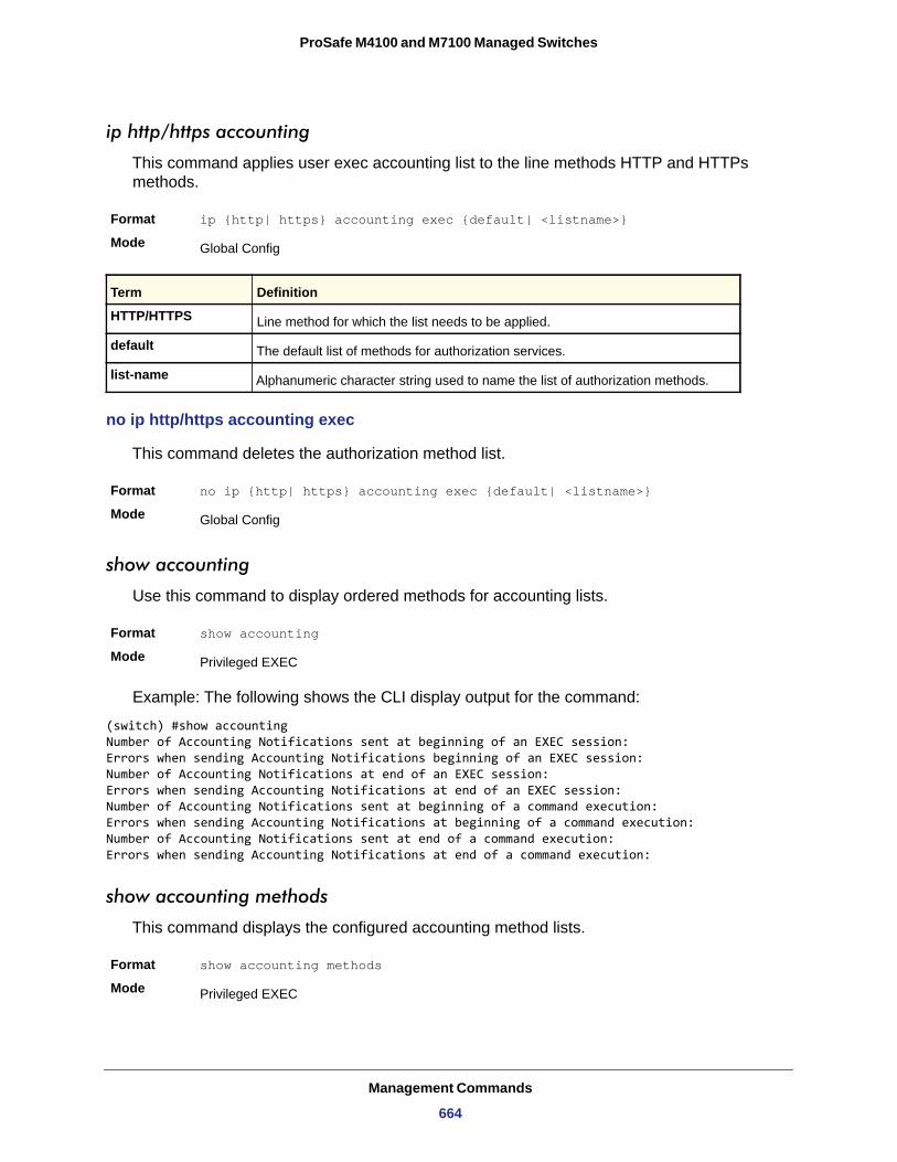
ProSafe M4100 and M7100 Managed Switches
ip http/https accounting
This command applies user exec accounting list to the line methods HTTP and HTTPs methods.
Format ip {http| https} accounting exec {default| <listname>}
Mode
HTTP/HTTPS
default
list-name
no ip http/https accounting exec
This command deletes the authorization method list.
Format no ip {http| https} accounting exec {default| <listname>}
Mode
show accounting
Use this command to display ordered methods for accounting lists.
Format show accounting
Mode
Example: The following shows the CLI display output for the command:
(switch) #show accountingNumber of Accounting Notifications sent at beginning of an EXEC session:Errors when sending Accounting Notifications beginning of an EXEC session:Number of Accounting Notifications at end of an EXEC session:Errors when sending Accounting Notifications at end of an EXEC session:Number of Accounting Notifications sent at beginning of a command execution:Errors when sending Accounting Notifications at beginning of a command execution:Number of Accounting Notifications sent at end of a command execution:Errors when sending Accounting Notifications at end of a command execution:
show accounting methods
This command displays the configured accounting method lists.
Format show accounting methods
Mode
Global Config
Term Definition
Line method for which the list needs to be applied.
The default list of methods for authorization services.
Alphanumeric character string used to name the list of authorization methods.
Global Config
Privileged EXEC
Privileged EXEC
Management Commands
664
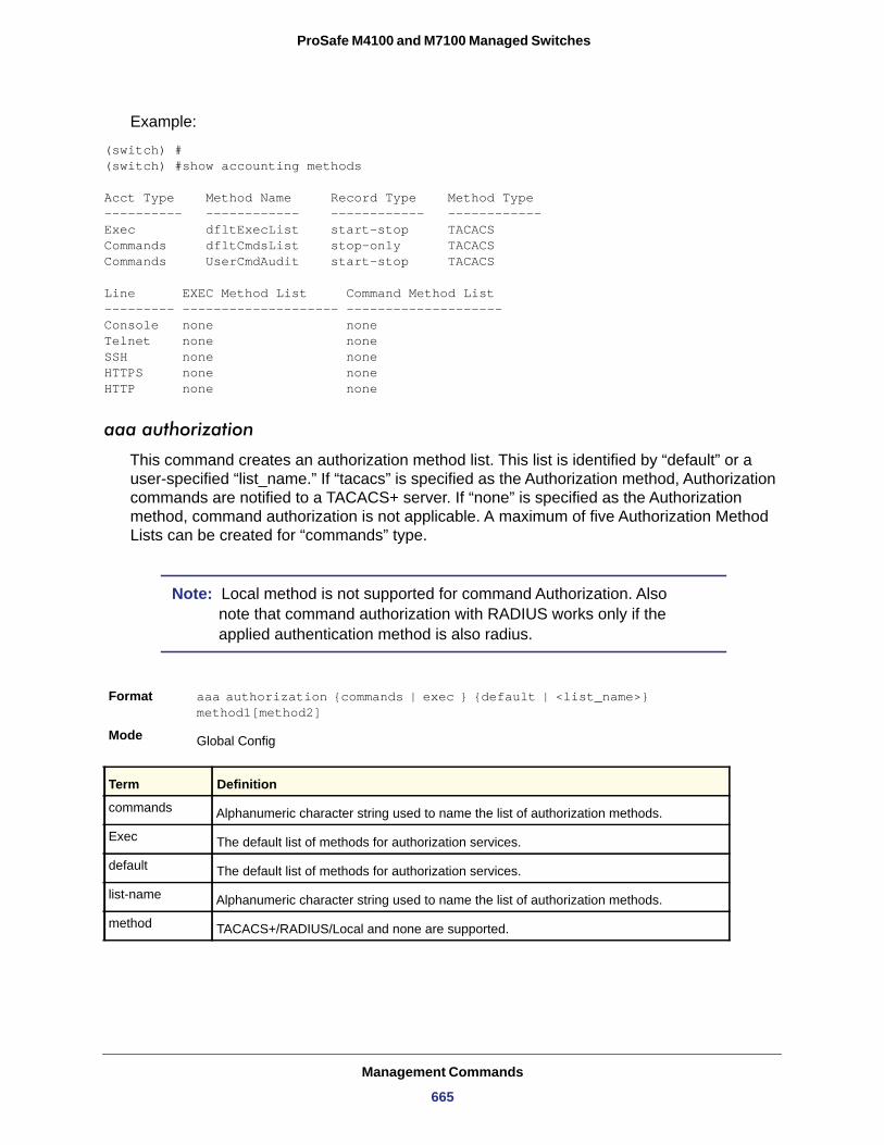
ProSafe M4100 and M7100 Managed Switches
Example:
(switch) #(switch) #show accounting methods
Acct Type Method Name Record Type Method Type---------- ------------ ------------ ------------Exec dfltExecList start-stop TACACSCommands dfltCmdsList stop-only TACACSCommands UserCmdAudit start-stop TACACS
Line EXEC Method List Command Method List--------- -------------------- --------------------Console none noneTelnet none noneSSH none noneHTTPS none noneHTTP none none
aaa authorization
This command creates an authorization method list. This list is identified by “default” or a user-specified “list_name.” If “tacacs” is specified as the Authorization method, Authorization commands are notified to a TACACS+ server. If “none” is specified as the Authorization method, command authorization is not applicable. A maximum of five Authorization Method Lists can be created for “commands” type.
Note: Local method is not supported for command Authorization. Also note that command authorization with RADIUS works only if the applied authentication method is also radius.
Format aaa authorization {commands | exec } {default | <list_name>} method1[method2]
Mode
commands
Exec
default
list-name
method
Global Config
Term Definition
Alphanumeric character string used to name the list of authorization methods.
The default list of methods for authorization services.
The default list of methods for authorization services.
Alphanumeric character string used to name the list of authorization methods.
TACACS+/RADIUS/Local and none are supported.
Management Commands
665
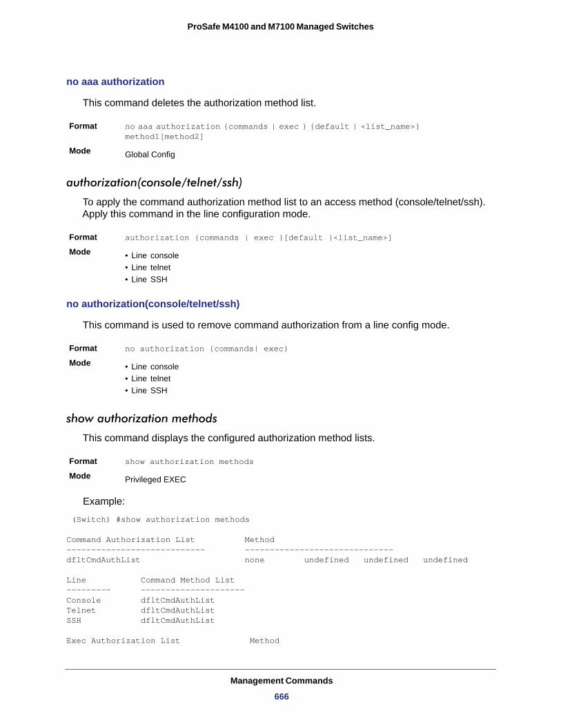
ProSafe M4100 and M7100 Managed Switches
no aaa authorization
This command deletes the authorization method list.
Format no aaa authorization {commands | exec } {default | <list_name>} method1[method2]
Mode
authorization(console/telnet/ssh)
To apply the command authorization method list to an access method (console/telnet/ssh). Apply this command in the line configuration mode.
Format authorization {commands | exec }[default |<list_name>]
Mode • Line console• Line telnet• Line SSH
no authorization(console/telnet/ssh)
This command is used to remove command authorization from a line config mode.
Format no authorization {commands| exec}
Mode • Line console• Line telnet• Line SSH
show authorization methods
This command displays the configured authorization method lists.
Format show authorization methods
Mode
Example:
(Switch) #show authorization methods
Command Authorization List Method---------------------------- ------------------------------dfltCmdAuthList none undefined undefined undefined
Line Command Method List--------- ---------------------Console dfltCmdAuthListTelnet dfltCmdAuthListSSH dfltCmdAuthList
Exec Authorization List Method
Global Config
Privileged EXEC
Management Commands
666
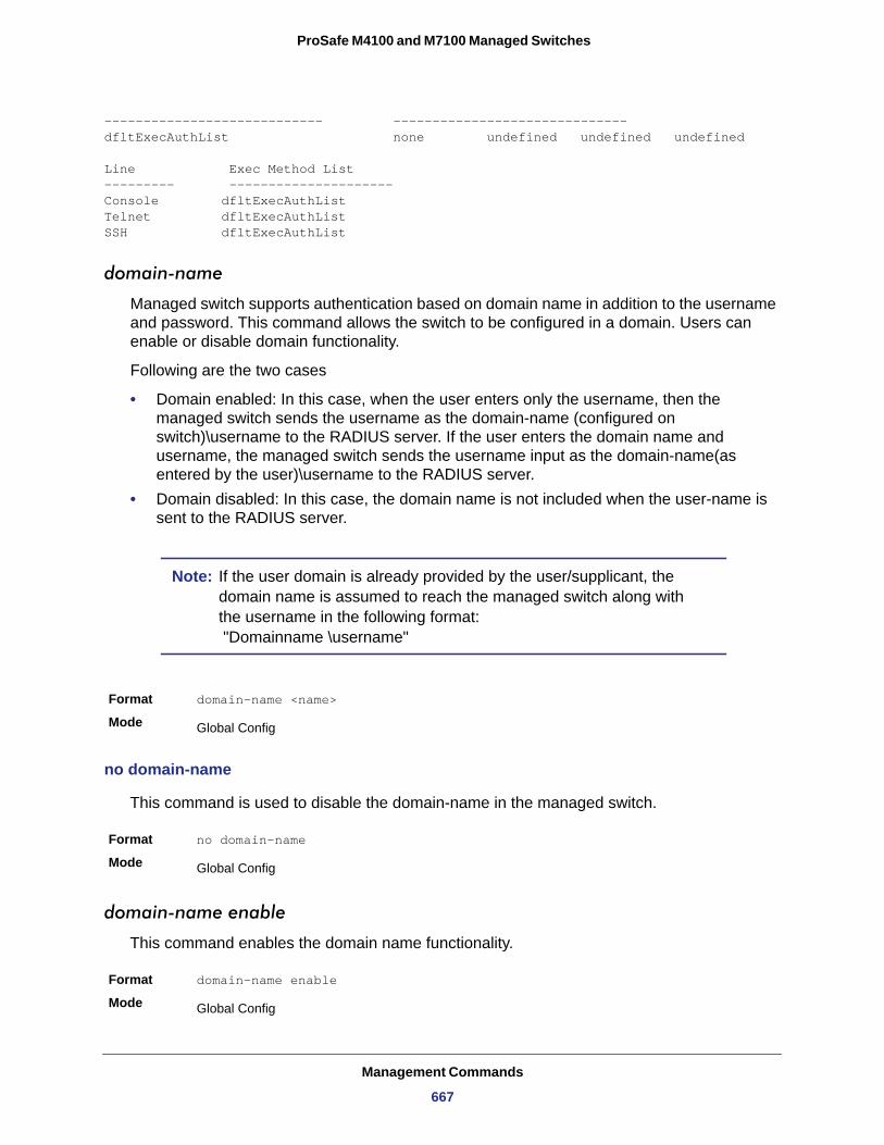
ProSafe M4100 and M7100 Managed Switches
---------------------------- ------------------------------dfltExecAuthList none undefined undefined undefined
Line Exec Method List--------- ---------------------Console dfltExecAuthListTelnet dfltExecAuthListSSH dfltExecAuthList
domain-name
Managed switch supports authentication based on domain name in addition to the username and password. This command allows the switch to be configured in a domain. Users can enable or disable domain functionality.
Following are the two cases
• Domain enabled: In this case, when the user enters only the username, then the managed switch sends the username as the domain-name (configured on switch)\username to the RADIUS server. If the user enters the domain name and username, the managed switch sends the username input as the domain-name(as entered by the user)\username to the RADIUS server.
• Domain disabled: In this case, the domain name is not included when the user-name is sent to the RADIUS server.
Note: If the user domain is already provided by the user/supplicant, the domain name is assumed to reach the managed switch along with the username in the following format: "Domainname \username"
Format domain-name <name>
Mode
no domain-name
This command is used to disable the domain-name in the managed switch.
Format no domain-name
Mode
domain-name enable
This command enables the domain name functionality.
Format domain-name enable
Mode
Global Config
Global Config
Global Config
Management Commands
667
ProSafe M4100 and M7100 Managed Switches
no domain-name enable
This command disables the domain name functionality.
Format no domain-name enable
Mode
show domain-name
This command displays the configured domain-name.
Format show domain-name
Mode
Example:
(switch) #(switch) #show domain-nameDomain : EnableDomain-name :abc
aaa ias-user username
The Internal Authentication Server (IAS) database is a dedicated internal database used for local authentication of users for network access through the IEEE 802.1X feature. Use this command to add the specified user to the internal user database. This command also changes the mode to AAA User Config mode.
Format aaa ias-username <user>
Mode
no aaa ias-user username
Use this command to remove an ias user.
Format no aaa ias-username <user>
Mode
Global Config
Privileged EXEC
Global Config
Global Config
Management Commands
668
ProSafe M4100 and M7100 Managed Switches
aaa session-id
This global aaa command specifies whether the same session-id is used for Authentication, Authorization, and Accounting service type within a session.
Default common
Format aaa session-id [common | unique]
Mode
common
unique
no aaa session-id
This command resets the aaa session-id behavior to default.
Format no aaa session-id [unique]
Mode
password (AAA IAS User Configuration)
Use this command to specify a password for a user in the IAS database.
Format password <password> [encrypted]
Mode
password
encrypted
no password(AAA IAS User Configuration)
Use this command to remove a password for a user in the IAS database.
Format no password
Mode
Global Config
Parameter Definition
Use the same session-id for all AAA Service types.
Use a unique session-id for AAA Service types.
Global Config
AAA IAS User Config
Parameter Definition
Password for this level. Range: 8-64 characters.
Encrypted password to be entered, copied from another switch configuration.
AAA IAS User Config
Management Commands
669
ProSafe M4100 and M7100 Managed Switches
clear aaa ias-users
Use this command to remove all users from the IAS database.
Format clear aaa ias-users
Mode
show aaa ias-users
Use this command to display configured IAS users and their attributes. Passwords configured are not shown in the show command output.
Format show aaa ias-users
Mode
SNMP Commands
This section describes the commands you use to configure Simple Network Management Protocol (SNMP) on the switch. You can configure the switch to act as an SNMP agent so that it can communicate with SNMP managers on your network.
snmp-server
Use this command to set the name and the physical location of the switch and the organization responsible for the network. The range for <name>, <loc> and <con> is from 1 to 31 alphanumeric characters.
Default
Format snmp-server {sysname <name> | location <loc> | contact <con>}
Mode
snmp-server community
Use this command to add (and name) a new SNMP community. A community <name> is a name associated with the switch and with a set of SNMP managers that manage it with a specified privileged level. The length of <name> can be up to 16 case-sensitive characters.
Note: Community names in the SNMP Community Table must be unique. When making multiple entries using the same community name, the first entry is kept and processed and all duplicate entries are ignored.
Privileged EXEC
Privileged EXEC
none
Global Config
Management Commands
670
ProSafe M4100 and M7100 Managed Switches
no snmp-server community
Use this command to remove this community name from the table. The <name> is the community name to be deleted.
Format no snmp-server community <name>
Mode
snmp-server community ipaddr
Use this command to set a client IP address for an SNMP community. The address is the associated community SNMP packet sending address and is used along with the client IP mask value to denote a range of IP addresses from which SNMP clients might use that community to access the device. A value of 0.0.0.0 allows access from any IP address. Otherwise, this value is ANDed with the mask to determine the range of allowed client IP addresses. The name is the applicable community name.
Default
Format snmp-server community ipaddr <ipaddr> <name>
Mode
no snmp-server community ipaddr
Use this command to set a client IP address for an SNMP community to 0.0.0.0. The name is the applicable community name.
Format no snmp-server community ipaddr <name>
Mode
snmp-server community ipmask
Use this command to set a client IP mask for an SNMP community. The address is the associated community SNMP packet sending address and is used along with the client IP address value to denote a range of IP addresses from which SNMP clients might use that community to access the device. A value of 255.255.255.255 will allow access from only one
Default • Public and private, which you can rename.• Default values for the remaining four community names are blank.
Format snmp-server community <name>
Mode Global Config
Global Config
0.0.0.0
Global Config
Global Config
Management Commands
671
ProSafe M4100 and M7100 Managed Switches
station, and will use that machine's IP address for the client IP address. A value of 0.0.0.0 will allow access from any IP address. The name is the applicable community name.
Default
Format snmp-server community ipmask <ipmask> <name>
Mode
no snmp-server community ipmask
Use this command to set a client IP mask for an SNMP community to 0.0.0.0. The name is the applicable community name. The community name might be up to 16 alphanumeric characters.
Format no snmp-server community ipmask <name>
Mode
snmp-server community mode
Use this command to activate an SNMP community. If a community is enabled, an SNMP manager associated with this community manages the switch according to its access right. If the community is disabled, no SNMP requests using this community are accepted. In this case the SNMP manager associated with this community cannot manage the switch until the Status is changed back to Enable.
Default • private and public communities - enabled• other four - disabled
Format snmp-server community mode <name>
Mode
no snmp-server community mode
Use this command to deactivate an SNMP community. If the community is disabled, no SNMP requests using this community are accepted. In this case the SNMP manager associated with this community cannot manage the switch until the Status is changed back to Enable.
Format no snmp-server community mode <name>
Mode
0.0.0.0
Global Config
Global Config
Global Config
Global Config
Management Commands
672
ProSafe M4100 and M7100 Managed Switches
snmp-server community ro
Use this command to restrict access to switch information. The access mode is read-only (also called public).
Format snmp-server community ro <name>
Mode
snmp-server community rw
Use this command to restrict access to switch information. The access mode is read/write (also called private).
Format snmp-server community rw <name>
Mode
snmp-server enable traps violation
Use this command to enable sending new violation traps designating when a packet with a disallowed MAC address is received on a locked port.
Note: For other port security commands, see Protected Ports Commands on page 64.
no snmp-server enable traps violation
Use this command to disable sending new violation traps.
Format no snmp-server enable traps violation
Mode
snmp-server enable traps
Use this command to enable the Authentication Flag.
Global Config
Global Config
Default disabled
Format snmp-server enable traps violation
Mode Interface Config
Interface Config
Default enabled
Management Commands
673
ProSafe M4100 and M7100 Managed Switches
no snmp-server enable traps
Use this command to disable the Authentication Flag.
Format no snmp-server enable traps
Mode
Note: This command might not be available on all platforms.
snmp-server enable traps linkmode
Use this command to enable Link Up/Down traps for the entire switch. When enabled, link traps are sent only if the Link Trap flag setting associated with the port is enabled. For more information, see snmp trap link-status on page 677
Default
Format snmp-server enable traps linkmode
Mode
no snmp-server enable traps linkmode
Use this command to disable Link Up/Down traps for the entire switch.
Format no snmp-server enable traps linkmode
Mode
snmp-server enable traps multiusers
Use this command to enable Multiple User traps. When the traps are enabled, a Multiple User Trap is sent when a user logs in to the terminal interface (EIA 232 or Telnet) and there is an existing terminal interface session.
Default
Format snmp-server enable traps multiusers
Mode
Format snmp-server enable traps
Mode Global Config
Global Config
enabled
Global Config
Global Config
enabled
Global Config
Management Commands
674
ProSafe M4100 and M7100 Managed Switches
no snmp-server enable traps multiusers
Use this command to disable Multiple User traps.
Format no snmp-server enable traps multiusers
Mode
snmp-server enable traps stpmode
Use this command to enable sending new root traps and topology change notification traps.
Default
Format snmp-server enable traps stpmode
Mode
no snmp-server enable traps stpmode
Use this command to disable sending new root traps and topology change notification traps.
Format no snmp-server enable traps stpmode
Mode
snmptrap
Use this command to add an SNMP trap receiver. The maximum length of <name> is 16 case-sensitive alphanumeric characters. The <snmpversion> is the version of SNMP. The version parameter options are snmpv1 or snmpv2. The SNMP trap address can be set using both an IPv4 address format as well as an IPv6 global address format.
The following shows an example of the CLI command.
(Netgear Switch)# snmptrap mytrap ip6addr 3099::2
Note: The <name> parameter does not need to be unique, however; the <name> and <ipaddr | hostname> pair must be unique. Multiple entries can exist with the same <name>, as long as they are associated with a different <ipaddr | hostname>. The reverse scenario is also acceptable. The <name> is the community name used when sending the trap to the receiver, but the <name> is not directly associated with the SNMP Community Table, See “snmp-server community” on page39.”
Global Config
enabled
Global Config
Global Config
Management Commands
675
ProSafe M4100 and M7100 Managed Switches
no snmptrap
Use this command to delete trap receivers for a community.
Format no snmptrap <name> {ipaddr <ipaddr|hostname> | ip6addr <ip6addr| hostname>}
Mode
snmptrap snmpversion
Use this command to modify the SNMP version of a trap. The maximum length of <name> is 16 case-sensitive alphanumeric characters. The <snmpversion> parameter options are snmpv1 or snmpv2.
Note: This command does not support a “no” form.
snmptrap ipaddr
Use this command to assign an IP address to a specified community name. The name can use up to 16 case-sensitive alphanumeric characters.
Note: IP addresses in the SNMP trap receiver table must be unique. If you make multiple entries using the same IP address, the first entry is retained and processed. All duplicate entries are ignored.
Default snmpv2
Format snmptrap <name> {ipaddr <ipaddr|hostname> | ip6addr <ip6addr| hostname>} [snmpversion <snmpversion>]
Mode Global Config
Global Config
Default snmpv2
Format snmptrap snmpversion <name> {<ipaddr | hostname> |<ip6addr|hostname>} {snmpv1|snmpv2}
Mode Global Config
Management Commands
676
ProSafe M4100 and M7100 Managed Switches
snmptrap mode
Use this command to activate or deactivate an SNMP trap. Enabled trap receivers are active (able to receive traps). Disabled trap receivers are inactive (not able to receive traps).
Format snmptrap mode <name> { <ipaddr | hostname> |<ip6addr |hostname>}
Mode
no snmptrap mode
Use this command to deactivate an SNMP trap. Disabled trap receivers are unable to receive traps.
Format no snmptrap mode <name> { <ipaddr | hostname> |<ip6addr |hostname>}
Mode
snmp trap link-status
Use this command to enable link status traps by interface.
Note: This command is valid only when the Link Up/Down Flag is enabled. For more information, see snmp-server enable traps linkmode on page 674.
no snmp trap link-status
Use this command to disable link status traps by interface.
Note: This command is valid only when the Link Up/Down Flag is enabled.
Format snmptrap ipaddr <name> <ipaddrold> <ipaddrnew | hostnamenew>
Mode Global Config
Global Config
Global Config
Format snmp trap link-status
Mode Interface Config
Management Commands
677
ProSafe M4100 and M7100 Managed Switches
snmp trap link-status all
Use this command to enable link status traps for all interfaces.
Note: This command is valid only when the Link Up/Down Flag is enabled. For more information, see snmp-server enable traps linkmode on page 674.
no snmp trap link-status all
Use this command to disable link status traps for all interfaces.
Note: This command is valid only when the Link Up/Down Flag is enabled. For more information, see snmp-server enable traps linkmode on page 674.
show snmpcommunity
Use this command to display SNMP community information. Six communities are supported. You can add, change, or delete communities. The switch does not need to be reset for changes to take effect.
The SNMP agent of the switch complies with SNMP Versions 1, 2 or 3. For more information about the SNMP specification, see the SNMP RFCs. The SNMP agent sends traps through
Format no snmp trap link-status
Mode Interface Config
Format snmp trap link-status all
Mode Global Config
Format no snmp trap link-status all
Mode Global Config
Management Commands
678
ProSafe M4100 and M7100 Managed Switches
TCP/IP to an external SNMP manager based on the SNMP configuration (the trap receiver and other SNMP community parameters).
Format show snmpcommunity
Mode
SNMP Community Name
Client IP Address
Client IP Mask
Access Mode
Status
show snmptrap
Use this command to display SNMP trap receivers. Trap messages are sent across a network to an SNMP Network Manager. These messages alert the manager to events occurring within the switch or on the network. Six trap receivers are simultaneously supported.
Format show snmptrap
Mode
SNMP Trap Name
IP Address
IPv6 Address
SNMP Version
Status
The following shows an example of the CLI command.
(Netgear Switch)#show snmptrap
Privileged EXEC
Term Definition
The community string to which this entry grants access. A valid entry is a case-sensitive alphanumeric string of up to 16 characters. Each row of this table must contain a unique community name.
An IP address (or portion thereof) from which this device will accept SNMP packets with the associated community. The requesting entity's IP address is ANDed with the Subnet Mask before being compared to the IP address. Note: If the Subnet Mask is set to 0.0.0.0, an IP address of 0.0.0.0 matches all IP addresses. The default value is 0.0.0.0.
A mask to be ANDed with the requesting entity's IP address before comparison with IP address. If the result matches with IP address then the address is an authenticated IP address. For example, if the IP address = 9.47.128.0 and the corresponding Subnet Mask = 255.255.255.0 a range of incoming IP addresses would match, i.e. the incoming IP address could equal 9.47.128.0 - 9.47.128.255. The default value is 0.0.0.0.
The access level for this community string.
The status of this community access entry.
Privileged EXEC
Term Definition
The community string of the SNMP trap packet sent to the trap manager. The string is case-sensitive and can be up to 16 alphanumeric characters.
The IPv4 address to receive SNMP traps from this device.
The IPv6 address to receive SNMP traps from this device.
SNMPv2
The receiver's status (enabled or disabled).
Management Commands
679
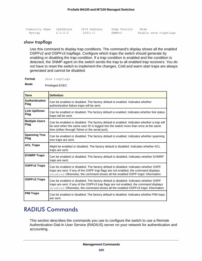
ProSafe M4100 and M7100 Managed Switches
Community Name IpAddress IPv6 Address Snmp Version Mode Mytrap 0.0.0.0 2001::1 SNMPv2 Enable show trapflags
show trapflags
Use this command to display trap conditions. The command’s display shows all the enabled OSPFv2 and OSPFv3 trapflags. Configure which traps the switch should generate by enabling or disabling the trap condition. If a trap condition is enabled and the condition is detected, the SNMP agent on the switch sends the trap to all enabled trap receivers. You do not have to reset the switch to implement the changes. Cold and warm start traps are always generated and cannot be disabled.
Format show trapflags
Mode
Authentication Flag
Link Up/Down Flag
Multiple Users Flag
Spanning Tree Flag
ACL Traps
DVMRP Traps
OSPFv2 Traps
OSPFv3 Traps
PIM Traps
RADIUS Commands
This section describes the commands you use to configure the switch to use a Remote Authentication Dial-In User Service (RADIUS) server on your network for authentication and accounting.
Privileged EXEC
Term Definition
Can be enabled or disabled. The factory default is enabled. Indicates whether authentication failure traps will be sent.
Can be enabled or disabled. The factory default is enabled. Indicates whether link status traps will be sent.
Can be enabled or disabled. The factory default is enabled. Indicates whether a trap will be sent when the same user ID is logged into the switch more than once at the same time (either through Telnet or the serial port).
Can be enabled or disabled. The factory default is enabled. Indicates whether spanning tree traps are sent.
Might be enabled or disabled. The factory default is disabled. Indicates whether ACL traps are sent.
Can be enabled or disabled. The factory default is disabled. Indicates whether DVMRP traps are sent.
Can be enabled or disabled. The factory default is disabled. Indicates whether OSPF traps are sent. If any of the OSPF trap flags are not enabled, the command displays disabled. Otherwise, the command shows all the enabled OSPF traps’ information.
Can be enabled or disabled. The factory default is disabled. Indicates whether OSPF traps are sent. If any of the OSPFv3 trap flags are not enabled, the command displays disabled. Otherwise, the command shows all the enabled OSPFv3 traps’ information.
Can be enabled or disabled. The factory default is disabled. Indicates whether PIM traps are sent.
Management Commands
680
ProSafe M4100 and M7100 Managed Switches
authorization network radius
Use this command to enable the switch to accept VLAN assignment by the radius server.
Default
Format authorization network radius
Mode
no authorization network radius
Use this command to disable the switch to accept VLAN assignment by the radius server.
Format no authorization network radius
Mode
radius accounting mode
Use this command to enable the RADIUS accounting function.
Default
Format radius accounting mode
Mode
no radius accounting mode
Use this command to set the RADIUS accounting function to the default value (disabled).
Format no radius accounting mode
Mode
radius server attribute
Use this command to specify the RADIUS client to use the NAS-IP Address attribute in the RADIUS requests. If the specific IP address is configured while enabling this attribute, the RADIUS client uses that IP address while sending NAS-IP-Address attribute in RADIUS communication.
Format radius server attribute <4> [<ipaddr>]
Mode
disable
Global Config
Global Config
disabled
Global Config
Global Config
Global Config
Term Definition
4 NAS-IP-Address attribute to be used in RADIUS requests.
ipaddr The IP address of the server.
Management Commands
681
ProSafe M4100 and M7100 Managed Switches
no radius server attribute
Use the no version of this command to disable the NAS-IP-Address attribute global parameter for RADIUS client. When this parameter is disabled, the RADIUS client does not send the NAS-IP-Address attribute in RADIUS requests.
Format no radius server attribute <4> [<ipaddr>]
Mode
The following shows an example of the command.
(Switch) (Config) #radius server attribute 4 192.168.37.60(Switch) (Config) #radius server attribute 4
radius server host
Use this command to configure the IP address or DNS name to use for communicating with the RADIUS server of a selected server type. While configuring the IP address or DNS name for the authenticating or accounting servers, you can also configure the port number and server name. If the authenticating and accounting servers are configured without a name, the command uses the ‘Default_RADIUS_Auth_Server’ and ‘Default_RADIUS_Acct_Server’ as the default names, respectively. The same name can be configured for more than one authenticating servers and the name should be unique for accounting servers. The RADIUS client allows the configuration of a maximum 32 authenticating and accounting servers.
If you use the <auth> parameter, the command configures the IP address or hostname to use to connect to a RADIUS authentication server. You can configure up to 3 servers per RADIUS client. If the maximum number of configured servers is reached, the command fails until you remove one of the servers by issuing the “no” form of the command. If you use the optional <port> parameter, the command configures the UDP port number to use when connecting to the configured RADIUS server. The <port> number range is 1 - 65535, with 1812 being the default value.
Note: To reconfigure a RADIUS authentication server to use the default UDP <port>, set the <port> parameter to 1812.
If you use the <acct> token, the command configures the IP address or hostname to use for the RADIUS accounting server. You can only configure one accounting server. If an accounting server is currently configured, use the “no” form of the command to remove it from the configuration. The IP address or hostname you specify must match that of a previously configured accounting server. If you use the optional <port> parameter, the command configures the UDP port to use when connecting to the RADIUS accounting server. If a <port> is already configured for the accounting server, the new <port> replaces the previously configured <port>. The <port> must be a value in the range 0 - 65535, with 1813 being the default.
Global Config
Management Commands
682
ProSafe M4100 and M7100 Managed Switches
Note: To reconfigure a RADIUS accounting server to use the default UDP <port>, set the <port> parameter to 1813.
no radius server host
Use the no version of this command to delete the configured server entry from the list of configured RADIUS servers. If the RADIUS authenticating server being removed is the active server in the servers that are identified by the same server name, then the RADIUS client selects another server for making RADIUS transactions. If the 'auth' token is used, the previously configured RADIUS authentication server is removed from the configuration. Similarly, if the 'acct' token is used, the previously configured RADIUS accounting server is removed from the configuration. The <ipaddr|dnsname> parameter must match the IP address or dns name of the previously configured RADIUS authentication / accounting server.
Format no radius server host {auth | acct} {<ipaddr|dnsname>}
Mode
The following shows an example of the command.
(Switch) (Config) #radius server host acct 192.168.37.60(Switch) (Config) #radius server host acct 192.168.37.60 port 1813(Switch) (Config) #radius server host auth 192.168.37.60 name Network1_RADIUS_Auth_Server port 1813
(Switch) (Config) #radius server host acct 192.168.37.60 name Network2_RADIUS_Auth_Server(Switch) (Config) #no radius server host acct 192.168.37.60
Format radius server host {auth | acct} {<ipaddr|dnsname>} [name <servername>] [port <0-65535>][server-type]
Mode Global Config
Field Description
ipaddr The IP address of the server.
dnsname The DNS name of the server.
0-65535 The port number to use to connect to the specified RADIUS server.
servername The alias name to identify the server.
Global Config
Management Commands
683
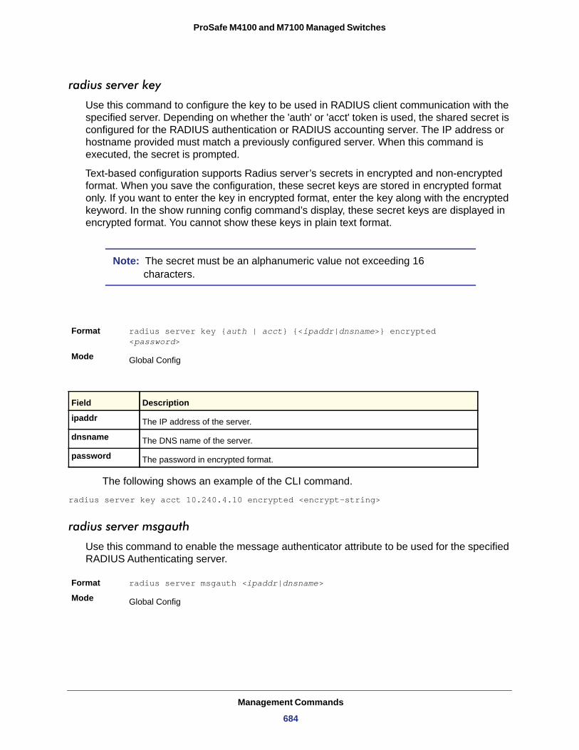
ProSafe M4100 and M7100 Managed Switches
radius server key
Use this command to configure the key to be used in RADIUS client communication with the specified server. Depending on whether the 'auth' or 'acct' token is used, the shared secret is configured for the RADIUS authentication or RADIUS accounting server. The IP address or hostname provided must match a previously configured server. When this command is executed, the secret is prompted.
Text-based configuration supports Radius server’s secrets in encrypted and non-encrypted format. When you save the configuration, these secret keys are stored in encrypted format only. If you want to enter the key in encrypted format, enter the key along with the encrypted keyword. In the show running config command’s display, these secret keys are displayed in encrypted format. You cannot show these keys in plain text format.
Note: The secret must be an alphanumeric value not exceeding 16 characters.
The following shows an example of the CLI command.
radius server key acct 10.240.4.10 encrypted <encrypt-string>
radius server msgauth
Use this command to enable the message authenticator attribute to be used for the specified RADIUS Authenticating server.
Format radius server msgauth <ipaddr|dnsname>
Mode
Format radius server key {auth | acct} {<ipaddr|dnsname>} encrypted <password>
Mode Global Config
Field Description
ipaddr The IP address of the server.
dnsname The DNS name of the server.
password The password in encrypted format.
Global Config
Management Commands
684
ProSafe M4100 and M7100 Managed Switches
no radius server msgauth
Use the no version of this command to disable the message authenticator attribute to be used for the specified RADIUS Authenticating server.
Format no radius server msgauth <ipaddr|dnsname>
Mode
radius server primary
Use this command to designate a configured server as the primary server in the group of servers that have the same server name. Multiple primary servers can be configured for each number of servers that have the same name. When the RADIUS client has to perform transactions with an authenticating RADIUS server of specified name, the client uses the primary server that has the specified server name by default. If the RADIUS client fails to communicate with the primary server for any reason, the client uses the backup servers configured with the same server name. These backup servers are identified as the ‘Secondary’ type.
Format radius server primary {<ipaddr|dnsname>}
Mode
radius server retransmit
Use this command to configure the global parameter for the RADIUS client that specifies the number of transmissions of the messages to be made before attempting the fall back server upon unsuccessful communication with the current RADIUS authenticating server. When the maximum number of retries are exhausted for the RADIUS accounting server and no response is received, the client does not communicate with any other server.
Default
Format radius server retransmit <retries>
Mode
Field Description
ip addr The IP address of the server.
dnsname The DNS name of the server.
Global Config
Global Config
Field Description
ip addr The IP address of the RADIUS Authenticating server.
dnsname The DNS name of the server.
4
Global Config
Management Commands
685
ProSafe M4100 and M7100 Managed Switches
no radius server retransmit
Use this command to set the value of this global parameter to the default value.
Format no radius server retransmit
Mode
radius server timeout
Use this command to configure the global parameter for the RADIUS client that specifies the timeout value (in seconds) after which a request must be retransmitted to the RADIUS server if no response is received. The timeout value is an integer in the range of 1–30.
Default
Format radius server timeout <seconds>
Mode
retries
no radius server timeout
Use this command to set the timeout global parameter to the default value.
Format no radius server timeout
Mode
show radius
Use this command to display the values configured for the global parameters of the RADIUS client.
Format show radius
Mode
Field Description
retries The maximum number of transmission attempts in the range of 1–15.
Global Config
5
Global Config
Field Description
Maximum number of transmission attempts in the range <1-30>.
Global Config
Privileged EXEC
Management Commands
686
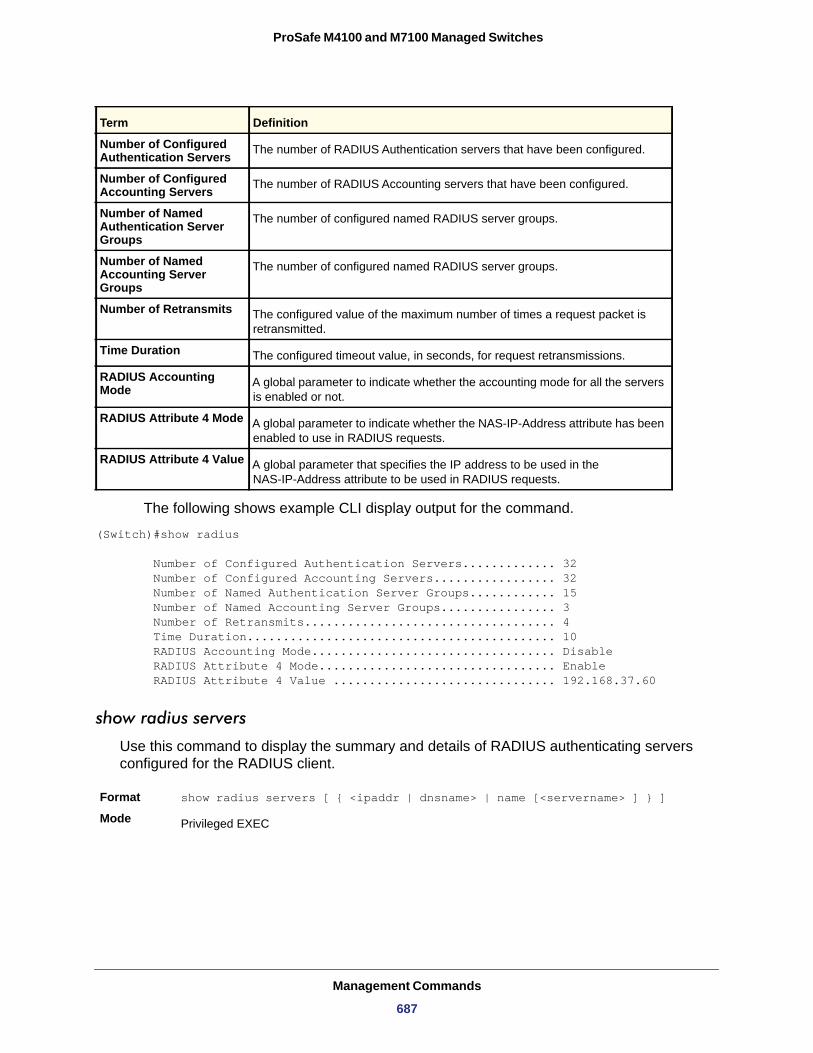
ProSafe M4100 and M7100 Managed Switches
Number of Configured Authentication Servers
Number of Configured Accounting Servers
Number of Named Authentication Server Groups
Number of Named Accounting Server Groups
Number of Retransmits
Time Duration
RADIUS Accounting Mode
RADIUS Attribute 4 Mode
RADIUS Attribute 4 Value
The following shows example CLI display output for the command.
(Switch)#show radius
Number of Configured Authentication Servers............. 32 Number of Configured Accounting Servers................. 32 Number of Named Authentication Server Groups............ 15 Number of Named Accounting Server Groups................ 3 Number of Retransmits................................... 4 Time Duration........................................... 10 RADIUS Accounting Mode.................................. Disable RADIUS Attribute 4 Mode................................. Enable RADIUS Attribute 4 Value ............................... 192.168.37.60
show radius servers
Use this command to display the summary and details of RADIUS authenticating servers configured for the RADIUS client.
Format show radius servers [ { <ipaddr | dnsname> | name [<servername> ] } ]
Mode
Term Definition
The number of RADIUS Authentication servers that have been configured.
The number of RADIUS Accounting servers that have been configured.
The number of configured named RADIUS server groups.
The number of configured named RADIUS server groups.
The configured value of the maximum number of times a request packet is retransmitted.
The configured timeout value, in seconds, for request retransmissions.
A global parameter to indicate whether the accounting mode for all the servers is enabled or not.
A global parameter to indicate whether the NAS-IP-Address attribute has been enabled to use in RADIUS requests.
A global parameter that specifies the IP address to be used in the NAS-IP-Address attribute to be used in RADIUS requests.
Privileged EXEC
Management Commands
687
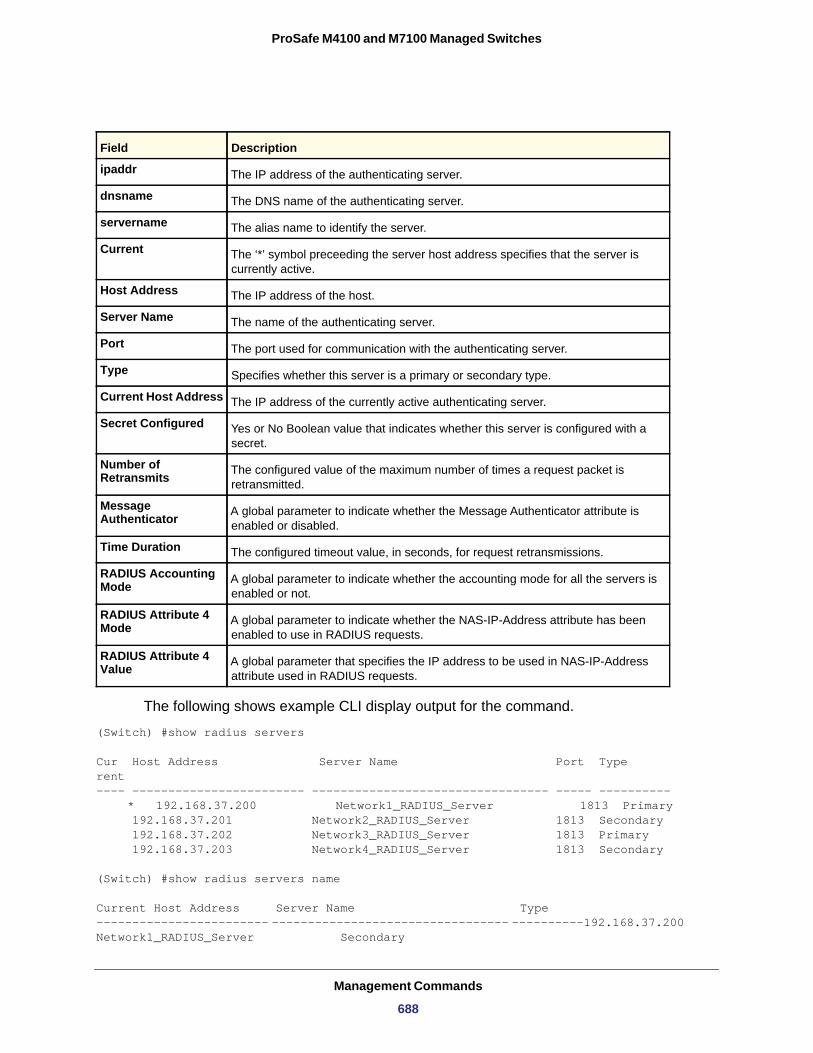
ProSafe M4100 and M7100 Managed Switches
The following shows example CLI display output for the command.
(Switch) #show radius servers
Cur Host Address Server Name Port Type rent---- ------------------------ --------------------------------- ----- ----------
* 192.168.37.200 Network1_RADIUS_Server 1813 Primary 192.168.37.201 Network2_RADIUS_Server 1813 Secondary 192.168.37.202 Network3_RADIUS_Server 1813 Primary 192.168.37.203 Network4_RADIUS_Server 1813 Secondary
(Switch) #show radius servers name
Current Host Address Server Name Type ------------------------ --------------------------------- ----------192.168.37.200 Network1_RADIUS_Server Secondary
Field Description
ipaddr The IP address of the authenticating server.
dnsname The DNS name of the authenticating server.
servername The alias name to identify the server.
Current The ‘*’ symbol preceeding the server host address specifies that the server is currently active.
Host Address The IP address of the host.
Server Name The name of the authenticating server.
Port The port used for communication with the authenticating server.
Type Specifies whether this server is a primary or secondary type.
Current Host Address The IP address of the currently active authenticating server.
Secret Configured Yes or No Boolean value that indicates whether this server is configured with a secret.
Number of Retransmits The configured value of the maximum number of times a request packet is
retransmitted.
Message Authenticator A global parameter to indicate whether the Message Authenticator attribute is
enabled or disabled.
Time Duration The configured timeout value, in seconds, for request retransmissions.
RADIUS Accounting Mode A global parameter to indicate whether the accounting mode for all the servers is
enabled or not.
RADIUS Attribute 4 Mode A global parameter to indicate whether the NAS-IP-Address attribute has been
enabled to use in RADIUS requests.
RADIUS Attribute 4 Value A global parameter that specifies the IP address to be used in NAS-IP-Address
attribute used in RADIUS requests.
Management Commands
688
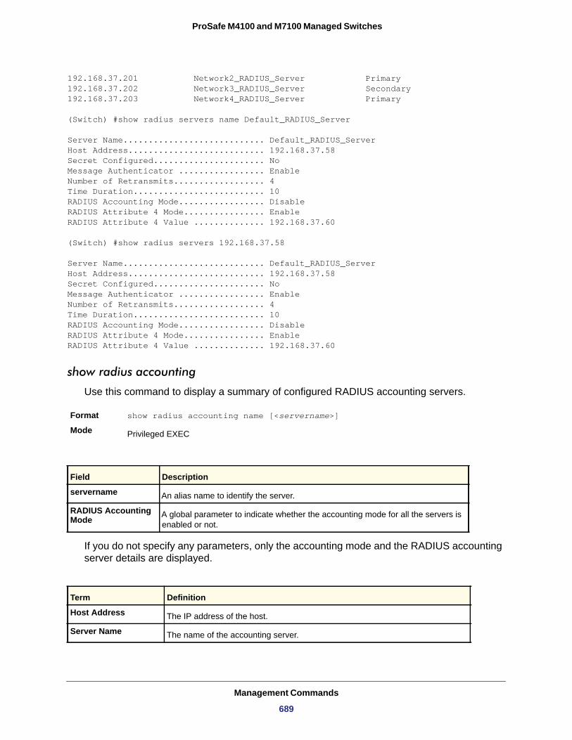
ProSafe M4100 and M7100 Managed Switches
192.168.37.201 Network2_RADIUS_Server Primary192.168.37.202 Network3_RADIUS_Server Secondary192.168.37.203 Network4_RADIUS_Server Primary
(Switch) #show radius servers name Default_RADIUS_Server
Server Name............................ Default_RADIUS_ServerHost Address........................... 192.168.37.58Secret Configured...................... NoMessage Authenticator ................. EnableNumber of Retransmits.................. 4Time Duration.......................... 10RADIUS Accounting Mode................. DisableRADIUS Attribute 4 Mode................ EnableRADIUS Attribute 4 Value .............. 192.168.37.60
(Switch) #show radius servers 192.168.37.58
Server Name............................ Default_RADIUS_ServerHost Address........................... 192.168.37.58Secret Configured...................... NoMessage Authenticator ................. EnableNumber of Retransmits.................. 4Time Duration.......................... 10RADIUS Accounting Mode................. DisableRADIUS Attribute 4 Mode................ EnableRADIUS Attribute 4 Value .............. 192.168.37.60
show radius accounting
Use this command to display a summary of configured RADIUS accounting servers.
Format show radius accounting name [<servername>]
Mode
If you do not specify any parameters, only the accounting mode and the RADIUS accounting server details are displayed.
Privileged EXEC
Field Description
servername An alias name to identify the server.
RADIUS Accounting Mode A global parameter to indicate whether the accounting mode for all the servers is
enabled or not.
Term Definition
Host Address The IP address of the host.
Server Name The name of the accounting server.
Management Commands
689
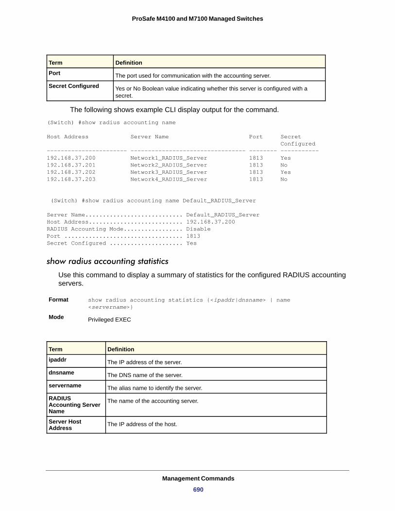
ProSafe M4100 and M7100 Managed Switches
The following shows example CLI display output for the command.
(Switch) #show radius accounting name
Host Address Server Name Port Secret Configured----------------------- --------------------------------- -------- -----------192.168.37.200 Network1_RADIUS_Server 1813 Yes192.168.37.201 Network2_RADIUS_Server 1813 No192.168.37.202 Network3_RADIUS_Server 1813 Yes192.168.37.203 Network4_RADIUS_Server 1813 No
(Switch) #show radius accounting name Default_RADIUS_Server
Server Name............................ Default_RADIUS_ServerHost Address........................... 192.168.37.200RADIUS Accounting Mode................. DisablePort .................................. 1813Secret Configured ..................... Yes
show radius accounting statistics
Use this command to display a summary of statistics for the configured RADIUS accounting servers.
Format show radius accounting statistics {<ipaddr|dnsname> | name <servername>}
Mode
Port The port used for communication with the accounting server.
Secret Configured Yes or No Boolean value indicating whether this server is configured with a secret.
Privileged EXEC
Term Definition
ipaddr The IP address of the server.
dnsname The DNS name of the server.
servername The alias name to identify the server.
RADIUS Accounting Server Name
The name of the accounting server.
Server Host Address The IP address of the host.
Term Definition
Management Commands
690
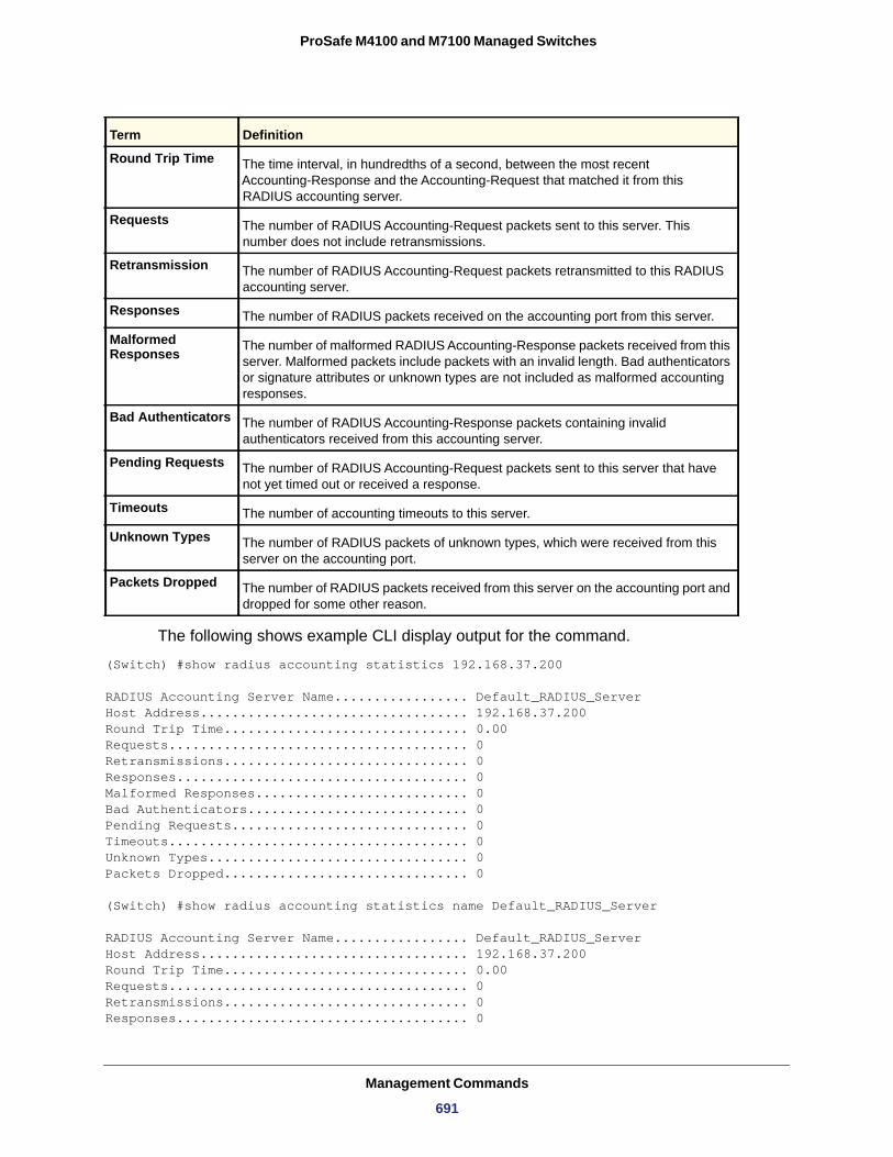
ProSafe M4100 and M7100 Managed Switches
The following shows example CLI display output for the command.
(Switch) #show radius accounting statistics 192.168.37.200
RADIUS Accounting Server Name................. Default_RADIUS_ServerHost Address.................................. 192.168.37.200Round Trip Time............................... 0.00Requests...................................... 0Retransmissions............................... 0Responses..................................... 0Malformed Responses........................... 0Bad Authenticators............................ 0Pending Requests.............................. 0Timeouts...................................... 0Unknown Types................................. 0Packets Dropped............................... 0
(Switch) #show radius accounting statistics name Default_RADIUS_Server
RADIUS Accounting Server Name................. Default_RADIUS_ServerHost Address.................................. 192.168.37.200Round Trip Time............................... 0.00Requests...................................... 0Retransmissions............................... 0Responses..................................... 0
Round Trip Time The time interval, in hundredths of a second, between the most recent Accounting-Response and the Accounting-Request that matched it from this RADIUS accounting server.
Requests The number of RADIUS Accounting-Request packets sent to this server. This number does not include retransmissions.
Retransmission The number of RADIUS Accounting-Request packets retransmitted to this RADIUS accounting server.
Responses The number of RADIUS packets received on the accounting port from this server.
Malformed Responses The number of malformed RADIUS Accounting-Response packets received from this
server. Malformed packets include packets with an invalid length. Bad authenticators or signature attributes or unknown types are not included as malformed accounting responses.
Bad Authenticators The number of RADIUS Accounting-Response packets containing invalid authenticators received from this accounting server.
Pending Requests The number of RADIUS Accounting-Request packets sent to this server that have not yet timed out or received a response.
Timeouts The number of accounting timeouts to this server.
Unknown Types The number of RADIUS packets of unknown types, which were received from this server on the accounting port.
Packets Dropped The number of RADIUS packets received from this server on the accounting port and dropped for some other reason.
Term Definition
Management Commands
691
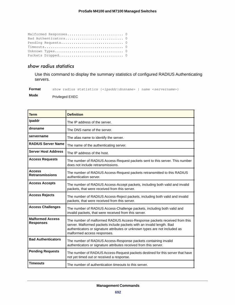
ProSafe M4100 and M7100 Managed Switches
Malformed Responses........................... 0Bad Authenticators............................ 0Pending Requests.............................. 0Timeouts...................................... 0Unknown Types................................. 0Packets Dropped............................... 0
show radius statistics
Use this command to display the summary statistics of configured RADIUS Authenticating servers.
Format show radius statistics {<ipaddr|dnsname> | name <servername>}
Mode Privileged EXEC
Term Definition
ipaddr The IP address of the server.
dnsname The DNS name of the server.
servername The alias name to identify the server.
RADIUS Server Name The name of the authenticating server.
Server Host Address The IP address of the host.
Access Requests The number of RADIUS Access-Request packets sent to this server. This number does not include retransmissions.
Access Retransmissions The number of RADIUS Access-Request packets retransmitted to this RADIUS
authentication server.
Access Accepts The number of RADIUS Access-Accept packets, including both valid and invalid packets, that were received from this server.
Access Rejects The number of RADIUS Access-Reject packets, including both valid and invalid packets, that were received from this server.
Access Challenges The number of RADIUS Access-Challenge packets, including both valid and invalid packets, that were received from this server.
Malformed Access Responses The number of malformed RADIUS Access-Response packets received from this
server. Malformed packets include packets with an invalid length. Bad authenticators or signature attributes or unknown types are not included as malformed access responses.
Bad Authenticators The number of RADIUS Access-Response packets containing invalid authenticators or signature attributes received from this server.
Pending Requests The number of RADIUS Access-Request packets destined for this server that have not yet timed out or received a response.
Timeouts The number of authentication timeouts to this server.
Management Commands
692
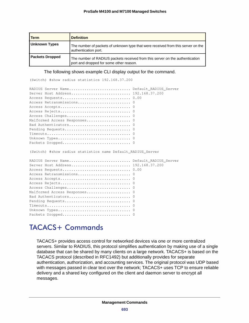
ProSafe M4100 and M7100 Managed Switches
The following shows example CLI display output for the command.
(Switch) #show radius statistics 192.168.37.200
RADIUS Server Name............................ Default_RADIUS_ServerServer Host Address........................... 192.168.37.200Access Requests............................... 0.00Access Retransmissions........................ 0Access Accepts................................ 0Access Rejects................................ 0Access Challenges............................. 0Malformed Access Responses.................... 0Bad Authenticators............................ 0Pending Requests.............................. 0Timeouts...................................... 0Unknown Types................................. 0Packets Dropped............................... 0
(Switch) #show radius statistics name Default_RADIUS_Server
RADIUS Server Name............................ Default_RADIUS_ServerServer Host Address........................... 192.168.37.200Access Requests............................... 0.00Access Retransmissions........................ 0Access Accepts................................ 0Access Rejects................................ 0Access Challenges............................. 0Malformed Access Responses.................... 0Bad Authenticators............................ 0Pending Requests.............................. 0Timeouts...................................... 0Unknown Types................................. 0Packets Dropped............................... 0
TACACS+ Commands
TACACS+ provides access control for networked devices via one or more centralized servers. Similar to RADIUS, this protocol simplifies authentication by making use of a single database that can be shared by many clients on a large network. TACACS+ is based on the TACACS protocol (described in RFC1492) but additionally provides for separate authentication, authorization, and accounting services. The original protocol was UDP based with messages passed in clear text over the network; TACACS+ uses TCP to ensure reliable delivery and a shared key configured on the client and daemon server to encrypt all messages.
Unknown Types The number of packets of unknown type that were received from this server on the authentication port.
Packets Dropped The number of RADIUS packets received from this server on the authentication port and dropped for some other reason.
Term Definition
Management Commands
693
ProSafe M4100 and M7100 Managed Switches
debug tacacs packet
Use the debug tacacs packet command to turn on TACACS+ packet debug.
Default
Format debug tacacs packet [receive | transmit]
Mode
no debug tacacs packet
Use this command to turn off TACACS+ packet debug.
Format no debug tacacs packetMode
tacacs-server host
Use the tacacs-server host command in Global Configuration mode to configure a TACACS+ server. This command enters into the TACACS+ configuration mode. The <ip-address|hostname> parameter is the IP address or hostname of the TACACS+ server. To specify multiple hosts, multiple tacacs-server host commands can be used.
Format tacacs-server host <ip-address|hostname>Mode
no tacacs-server host
Use the no tacacs-server host command to delete the specified hostname or IP address. The <ip-address|hostname> parameter is the IP address of the TACACS+ server.
Format no tacacs-server host <ip-address|hostname>Mode
tacacs-server key
Use the tacacs-server key command to set the authentication and encryption key for all TACACS+ communications between the switch and the TACACS+ daemon. The <key-string> parameter has a range of 0–128 characters and specifies the authentication and encryption key for all TACACS communications between the switch and the TACACS+ server. This key must match the key used on the TACACS+ daemon.
Text-based configuration supports TACACS server’s secrets in encrypted and non-encrypted format. When you save the configuration, these secret keys are stored in encrypted format only. If you want to enter the key in encrypted format, enter the key along with the encrypted
Disabled
Global Config
Global Config
Global Config
Global Config
Management Commands
694
ProSafe M4100 and M7100 Managed Switches
keyword. In the show running config command’s display, these secret keys are displayed in encrypted format. You cannot show these keys in plain text format.
Format tacacs-server key [<key-string> | encrypted <key-string>]Mode
no tacacs-server key
Use the no tacacs-server key command to disable the authentication and encryption key for all TACACS+ communications between the switch and the TACACS+ daemon. The <key-string> parameter has a range of 0–128 characters This key must match the key used on the TACACS+ daemon.
Format no tacacs-server key <key-string>Mode
tacacs-server keystring
Use this command to set the global authentication encryption key used for all TACACS+ communications between the TACACS+ server and the client.
Format tacacs-server keystring
Mode
tacacs-server source interface
Use this command in Global Configuration mode to configure the global source interface (Source IP selection) for all TACACS+ communications between the TACACS+ client and the server.
Format tacacs-server source-interface {<slot/port> | loopback <loopback-id> | VLAN <vlan-id>}
Mode
Global Config
Global Config
Global Config
Global Config
Parameter Description
slot/port The unit identifier assigned to the switch.
loopback-id The loopback interface. The range of the loopback ID is 0–7.
vlan-id The vlan id. The range of the vlan ID is 1–4,093.
Management Commands
695
ProSafe M4100 and M7100 Managed Switches
no tacacs-server source interface
Use this command in Global Configuration mode to remove the global source interface (Source IP selection) for all TACACS+ communications between the TACACS+ client and the server.
Format no tacacs-server source-interface
Mode
tacacs-server timeout
Use the tacacs-server timeout command to set the timeout value for communication with the TACACS+ servers. The <timeout> parameter has a range of 1-30 and is the timeout value in seconds.
Default
Format tacacs-server timeout <timeout>
Mode
no tacacs-server timeout
Use the no tacacs-server timeout command to restore the default timeout value for all TACACS servers.
Format no tacacs-server timeout
Mode
key
Use the key command in TACACS Configuration mode to specify the authentication and encryption key for all TACACS communications between the device and the TACACS server. This key must match the key used on the TACACS daemon. The <key-string> parameter specifies the key name. For an empty string use “ ”. (Range: 0 - 128 characters).
Text-based configuration supports TACACS server’s secrets in encrypted and non-encrypted format. When you save the configuration, these secret keys are stored in encrypted format only. If you want to enter the key in encrypted format, enter the key along with the encrypted keyword. In the show running config command’s display, these secret keys are displayed in encrypted format. You cannot show these keys in plain text format.
Format key [<key-string> | encrypted <key-string>]Mode
Privileged Exec
5
Global Config
Global Config
TACACS Config
Management Commands
696
ProSafe M4100 and M7100 Managed Switches
port
Use the port command in TACACS Configuration mode to specify a server port number. The server <port-number> range is 0 - 65535.
Default
Format port <port-number>Mode
priority
Use the priority command in TACACS Configuration mode to specify the order in which servers are used, where 0 (zero) is the highest priority. The <priority> parameter specifies the priority for servers. The highest priority is 0 (zero), and the range is 0 - 65535.
Default
Format priority <priority>Mode
timeout
Use the timeout command in TACACS Configuration mode to specify the timeout value in seconds. If no timeout value is specified, the global value is used. The <timeout> parameter has a range of 1-30 and is the timeout value in seconds.
Format timeout <timeout>Mode
show tacacs
Use the show tacacs command to display the configuration and statistics of a TACACS+ server.
Format show tacacs [<ip-address|hostname>]Mode
Host Address
Port
TimeOut
Priority
49
TACACS Config
0
TACACS Config
TACACS Config
Privileged EXEC
Term Definition
The IP address or hostname of the configured TACACS+ server.
The configured TACACS+ server port number.
The timeout in seconds for establishing a TCP connection.
The preference order in which TACACS+ servers are contacted. If a server connection fails, the next highest priority server is contacted.
Management Commands
697
ProSafe M4100 and M7100 Managed Switches
Configuration Scripting Commands
Configuration Scripting allows you to generate text-formatted script files representing the current configuration of a system. You can upload these configuration script files to a computer or UNIX system and edit them. Then, you can download the edited files to the system and apply the new configuration. You can apply configuration scripts to one or more switches with no or minor modifications.
Use the show running-config command (see show running-config on page 530) to capture the running configuration into a script. Use the copy command (see copy on page 553) to transfer the configuration script to or from the switch.
You should use scripts on systems with default configuration; however, you are not prevented from applying scripts on systems with non-default configurations.
Scripts must conform to the following rules:
• Script files are not distributed across the stack, and only live in the unit that is the master unit at the time of the file download.
• The file extension must be “.scr”.• A maximum of ten scripts are allowed on the switch.• The combined size of all script files on the switch shall not exceed 2048 KB.• The maximum number of configuration file command lines is 2000.
You can type single-line annotations at the command prompt to use when you write test or configuration scripts to improve script readability. The exclamation point (!) character flags the beginning of a comment. The comment flag character can begin a word anywhere on the command line, and all input following this character is ignored. Any command line that begins with the “!” character is recognized as a comment line and ignored by the parser.
The following lines show an example of a script:
! Script file for displaying management access
show telnet !Displays the information about remote connections
! Display information about direct connections
show serial
! End of the script file!
Note: To specify a blank password for a user in the configuration script, you must specify it as a space within quotes. For example, to change the password for user jane from a blank password to hello, the script entry is as follows:
users passwd jane
Management Commands
698
ProSafe M4100 and M7100 Managed Switches
" " hello hello
script apply
Use this command to apply the commands in the script to the switch. The <scriptname> parameter is the name of the script to apply.
Format script apply <scriptname>Mode
script delete
Use this command to delete a specified script, where the <scriptname> parameter is the name of the script to delete. The <all> option deletes all the scripts present on the switch.
Format script delete {<scriptname> | all} Mode
script list
Use this command to list all scripts present on the switch as well as the remaining available space.
Format script list
Mode
Configuration Script
Size
script show
Use this command to display the contents of a script file, which is named <scriptname>.
Format script show <scriptname>Mode
Output Format
Privileged EXEC
Privileged EXEC
Global Config
Term Definition
Name of the script.
Privileged EXEC
Privileged EXEC
Term Definition
line <number>: <line contents>
Management Commands
699
ProSafe M4100 and M7100 Managed Switches
script validate
Use this command to validate a script file by parsing each line in the script file, where <scriptname> is the name of the script to validate. The validate option is intended to be used as a tool for script development. Validation identifies potential problems. It might not identify all problems with a given script on any given device.
Format script validate <scriptname> Mode
Pre-Login Banner and System Prompt Commands
This section describes the commands you use to configure the pre-login banner and the system prompt. The pre-login banner is the text that displays before you login at the User: prompt.
copy (pre-login banner)
Use a copy command option to upload or download the CLI Banner to or from the switch. You can specify local URLs by using TFTP, Xmodem, Ymodem, or Zmodem.
Note: <ip6address> is also a valid parameter for routing packages that support IPv6.
set prompt
Use this command to change the name of the prompt. The length of name might be up to 64 alphanumeric characters.
Format set prompt <prompt_string>
Mode
Privileged EXEC
Format copy <url> nvram:clibannercopy nvram:clibanner <url>
Mode Privileged EXEC
Privileged EXEC
Management Commands
700
ProSafe M4100 and M7100 Managed Switches
set clibanner
Use this command to add the CLI Banner. The banner message supports up to 2000 characters.
Format set clibanner <line>
Mode
no set clibanner
Use this command to remove the CLI Banner downloaded through TFTP.
Format no set clibanner
Mode
Switch Database Management (SDM) Templates
You can use SDM templates to configure system resources in the switch and optimize support for specific features depending on how the switch is used in the network. You can select a template to provide the maximum system usage for a specific function. For example, you could use a routing template to optimize resources for IPv4 routing if the network environment does not use IPv6 routing.
Note the following:
• If you configure an SDM template, you must reload the switch for the configuration to take effect.
• If you try to configure IPv6 routing without first selecting the dual IPv4-IPv6 routing template, a warning message appears.
sdm prefer
Use this command to specify the SDM template to use on the switch.
Default
Format sdm prefer {ipv4-routing {default | data-center} | dual-ipv4-and-ipv6 {default}}
Mode
Global Config
Global Config
ipv4-routing for IPv4 only builds, dual-ipv4-ipv6 for IPv6 builds
Global Config
Management Commands
701
ProSafe M4100 and M7100 Managed Switches
ipv4-routing
dual-ipv4-and-ipv6
no sdm prefer
Use this command to return to the default template.
Format no sdm prefer
Mode
show sdm prefer
Use this command to view the currently active SDM template and its scaling parameters, or to view the scaling parameters for an inactive template. When used with no optional keywords, this command lists the currently active template and the template that will become active on the next reboot, if it is different from the currently active template. If the system boots with a non-default template and you clear the template configuration either using no sdm prefer or by deleting the startup configuration, show sdm prefer lists the default template as the next active template.
Use the optional keywords to list the scaling parameters of a specific template.
Format show sdm prefer [dual-ipv4-and-ipv6 default | ipv4-routing {default | data-center} ]
Mode
Parameter Description
Supports IPv4 routing only. -data-center: Support more ECMP next hops in IPv4 routes.-default: The routing template maximizes system resources for unicast routing, typically required for a router in the center of a network.
Supports both IPv4 and IPv6 routing.This option is visible only when the switch supports IPv6 and IPv4 routing. -default: Balance IPv4 and IPv6 Layer 2 and Layer 3 functionality.
Global Config
Privileged EXEC
Term Description
ARP Entries The maximum number of entries in the IPv4 Address Resolution Protocol (ARP) cache for routing interfaces.
IPv4 Unicast Routes The maximum number of IPv4 unicast forwarding table entries.
IPv6 NDP Entries The maximum number of IPv6 Neighbor Discovery Protocol (NDP) cache entries.
IPv6 Unicast Routes The maximum number of IPv6 unicast forwarding table entries.
ECMP Next Hops The maximum number of next hops that can be installed in the IPv4 and IPv6 unicast forwarding tables.
Management Commands
702
ProSafe M4100 and M7100 Managed Switches
Example:
#show sdm prefer Current template: Dual IPv4 and IPv6ARP Entries.................................... 4096 IPv4 Unicast Routes............................ 6112 IPv6 NDP Entries............................... 2048 IPv6 Unicast Routes............................ 3072 ECMP Next Hops................................. 4 IPv4 Multicast Routes........................... 256 IPv6 Multicast Routes.......................... 256
IPv6 Management Commands
IPv6 Management commands allow a device to be managed via an IPv6 address in a switch or IPv4 routing (that is, independent from the IPv6 Routing package). For Routing/IPv6 builds of Switch CLI dual IPv4/IPv6 operation over the service port is enabled. Switch CLI has capabilities such as:
• Static assignment of IPv6 addresses and gateways for the network ports.• The ability to ping an IPv6 link-local address over the network port. • Using IPv6 Management commands, you can send SNMP traps and queries via the
network port. • The user can manage a device via the network port (in addition to a routing interface).
network ipv6 enable
Use this command to enable IPv6 operation on the network port.
Default
Format network ipv6 enable
Mode
no network ipv6 enable
Use this command to disable IPv6 operation on the network port.
Format no network ipv6 enable
Mode
IPv4 Multicast Routes The maximum number of IPv4 multicast forwarding table entries.
IPv6 Multicast Routes The maximum number of IPv6 multicast forwarding table entries.
enabled
Privileged EXEC
Privileged EXEC
Term Description
Management Commands
703
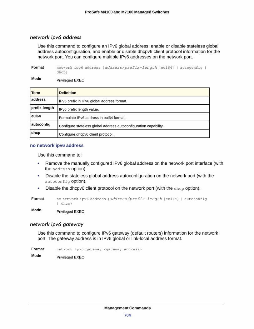
ProSafe M4100 and M7100 Managed Switches
network ipv6 address
Use this command to configure an IPv6 global address, enable or disable stateless global address autoconfiguration, and enable or disable dhcpv6 client protocol information for the network port. You can configure multiple IPv6 addresses on the network port.
Format network ipv6 address {address/prefix-length [eui64] | autoconfig | dhcp}
Mode
address
prefix-length
eui64
autoconfig
dhcp
no network ipv6 address
Use this command to:
• Remove the manually configured IPv6 global address on the network port interface (with the address option).
• Disable the stateless global address autoconfiguration on the network port (with the autoconfig option).
• Disable the dhcpv6 client protocol on the network port (with the dhcp option).
Format no network ipv6 address {address/prefix-length [eui64] | autoconfig | dhcp}
Mode
network ipv6 gateway
Use this command to configure IPv6 gateway (default routers) information for the network port. The gateway address is in IPv6 global or link-local address format.
Format network ipv6 gateway <gateway-address>
Mode
Privileged EXEC
Term Definition
IPv6 prefix in IPv6 global address format.
IPv6 prefix length value.
Formulate IPv6 address in eui64 format.
Configure stateless global address autoconfiguration capability.
Configure dhcpv6 client protocol.
Privileged EXEC
Privileged EXEC
Management Commands
704
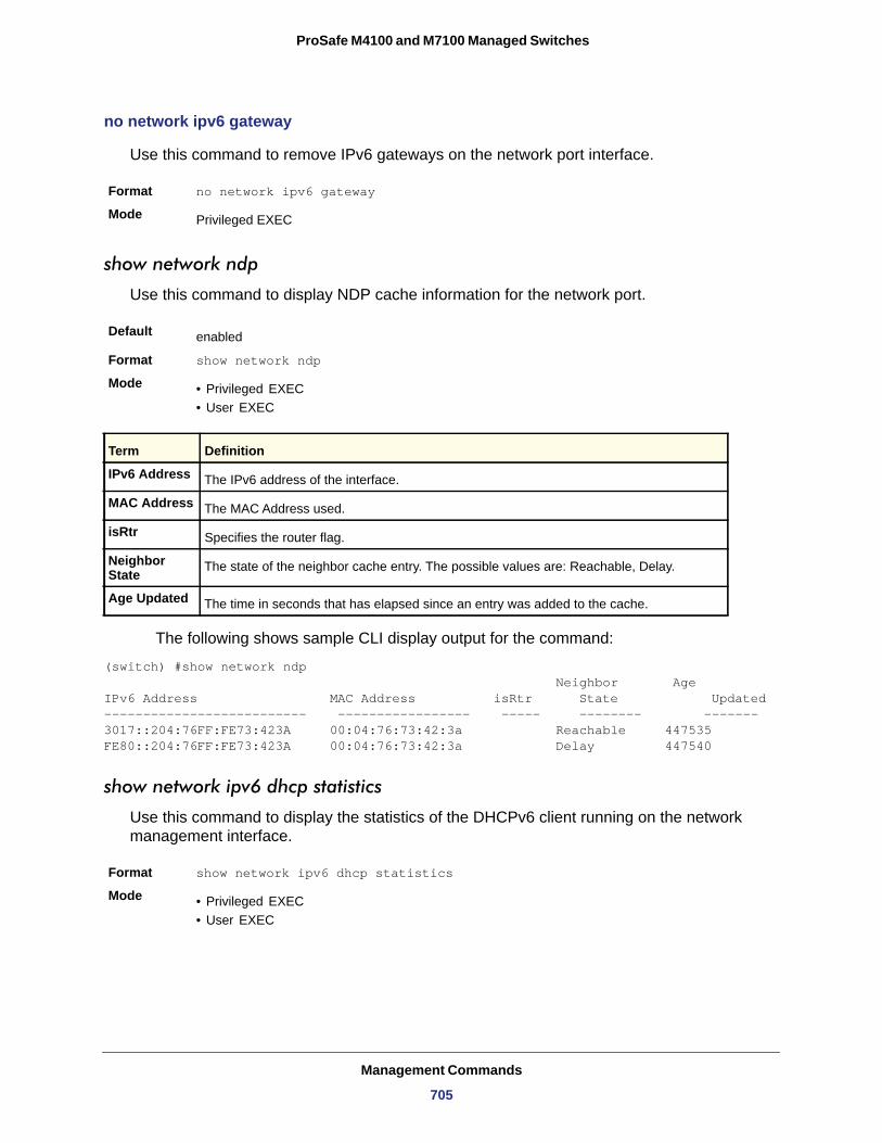
ProSafe M4100 and M7100 Managed Switches
no network ipv6 gateway
Use this command to remove IPv6 gateways on the network port interface.
Format no network ipv6 gateway
Mode
show network ndp
Use this command to display NDP cache information for the network port.
Default
Format show network ndp
Mode • Privileged EXEC• User EXEC
IPv6 Address
MAC Address
isRtr
Neighbor State
Age Updated
The following shows sample CLI display output for the command:
(switch) #show network ndp Neighbor AgeIPv6 Address MAC Address isRtr State Updated -------------------------- ----------------- ----- -------- ------- 3017::204:76FF:FE73:423A 00:04:76:73:42:3a Reachable 447535FE80::204:76FF:FE73:423A 00:04:76:73:42:3a Delay 447540
show network ipv6 dhcp statistics
Use this command to display the statistics of the DHCPv6 client running on the network management interface.
Format show network ipv6 dhcp statistics
Mode • Privileged EXEC• User EXEC
Privileged EXEC
enabled
Term Definition
The IPv6 address of the interface.
The MAC Address used.
Specifies the router flag.
The state of the neighbor cache entry. The possible values are: Reachable, Delay.
The time in seconds that has elapsed since an entry was added to the cache.
Management Commands
705
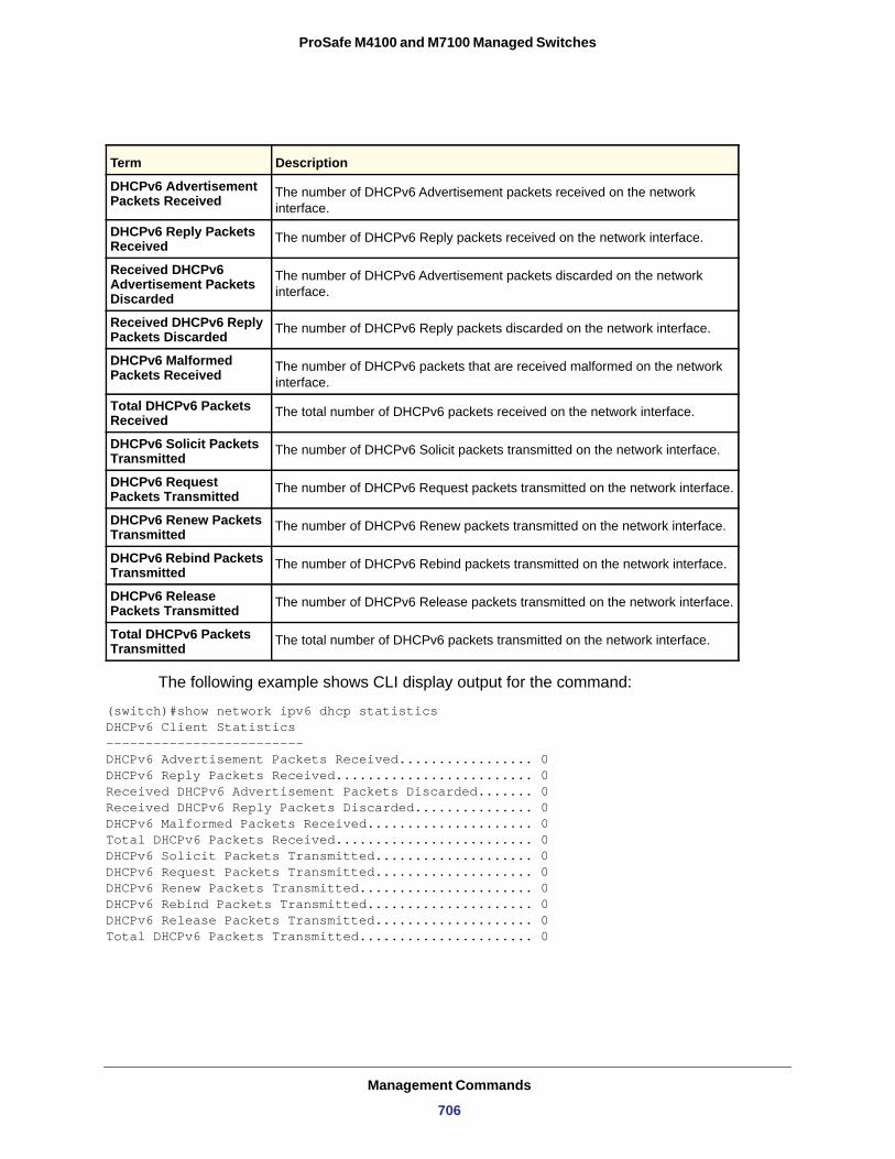
ProSafe M4100 and M7100 Managed Switches
The following example shows CLI display output for the command:
(switch)#show network ipv6 dhcp statisticsDHCPv6 Client Statistics-------------------------DHCPv6 Advertisement Packets Received................. 0DHCPv6 Reply Packets Received......................... 0Received DHCPv6 Advertisement Packets Discarded....... 0Received DHCPv6 Reply Packets Discarded............... 0DHCPv6 Malformed Packets Received..................... 0Total DHCPv6 Packets Received......................... 0DHCPv6 Solicit Packets Transmitted.................... 0DHCPv6 Request Packets Transmitted.................... 0DHCPv6 Renew Packets Transmitted...................... 0DHCPv6 Rebind Packets Transmitted..................... 0DHCPv6 Release Packets Transmitted.................... 0Total DHCPv6 Packets Transmitted...................... 0
Term Description
DHCPv6 Advertisement Packets Received The number of DHCPv6 Advertisement packets received on the network
interface.
DHCPv6 Reply Packets Received The number of DHCPv6 Reply packets received on the network interface.
Received DHCPv6 Advertisement Packets Discarded
The number of DHCPv6 Advertisement packets discarded on the network interface.
Received DHCPv6 Reply Packets Discarded The number of DHCPv6 Reply packets discarded on the network interface.
DHCPv6 Malformed Packets Received The number of DHCPv6 packets that are received malformed on the network
interface.
Total DHCPv6 Packets Received The total number of DHCPv6 packets received on the network interface.
DHCPv6 Solicit Packets Transmitted The number of DHCPv6 Solicit packets transmitted on the network interface.
DHCPv6 Request Packets Transmitted The number of DHCPv6 Request packets transmitted on the network interface.
DHCPv6 Renew Packets Transmitted The number of DHCPv6 Renew packets transmitted on the network interface.
DHCPv6 Rebind Packets Transmitted The number of DHCPv6 Rebind packets transmitted on the network interface.
DHCPv6 Release Packets Transmitted The number of DHCPv6 Release packets transmitted on the network interface.
Total DHCPv6 Packets Transmitted The total number of DHCPv6 packets transmitted on the network interface.
Management Commands
706
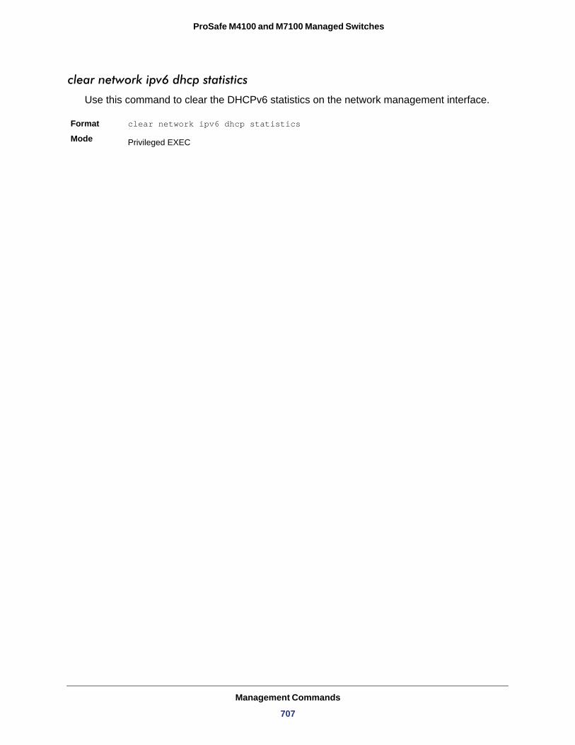
ProSafe M4100 and M7100 Managed Switches
clear network ipv6 dhcp statistics
Use this command to clear the DHCPv6 statistics on the network management interface.
Format clear network ipv6 dhcp statistics
Mode Privileged EXEC
Management Commands
707
2
112. Log MessagesThis chapter lists common log messages, along with information regarding the cause of each message. There is no specific action that can be taken per message. When there is a problem being diagnosed, a set of these messages in the event log, along with an understanding of the system configuration and details of the problem will assist NETGEAR, Inc. in determining the root cause of such a problem.
Note: This chapter does not contain a complete list of all syslog messages.
This chapter contains the following sections:
• Core • Utilities • Management • Switching • QoS • Routing/IPv6 Routing • Multicast • Stacking • Technologies • O/S Support
708
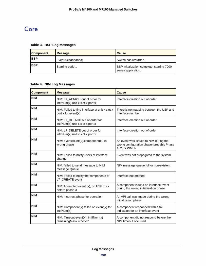
ProSafe M4100 and M7100 Managed Switches
Core
Table 3. BSP Log Messages
Component Message Cause
BSP Event(0xaaaaaaaa) Switch has restarted.
BSP Starting code... BSP initialization complete, starting 7000 series application.
Table 4. NIM Log Messages
Component Message Cause
NIM NIM: L7_ATTACH out of order for intIfNum(x) unit x slot x port x
Interface creation out of order
NIM NIM: Failed to find interface at unit x slot x port x for event(x)
There is no mapping between the USP and Interface number
NIM NIM: L7_DETACH out of order for intIfNum(x) unit x slot x port x
Interface creation out of order
NIM NIM: L7_DELETE out of order for intIfNum(x) unit x slot x port x
Interface creation out of order
NIM NIM: event(x),intf(x),component(x), in wrong phase
An event was issued to NIM during the wrong configuration phase (probably Phase 1, 2, or WMU)
NIM NIM: Failed to notify users of interface change
Event was not propagated to the system
NIM NIM: failed to send message to NIM message Queue.
NIM message queue full or non-existent
NIM NIM: Failed to notify the components of L7_CREATE event
Interface not created
NIM NIM: Attempted event (x), on USP x.x.x before phase 3
A component issued an interface event during the wrong initialization phase
NIM NIM: incorrect phase for operation An API call was made during the wrong initialization phase
NIM NIM: Component(x) failed on event(x) for intIfNum(x)
A component responded with a fail indication for an interface event
NIM NIM: Timeout event(x), intIfNum(x) remainingMask = “xxxx”
A component did not respond before the NIM timeout occurred
Log Messages
709
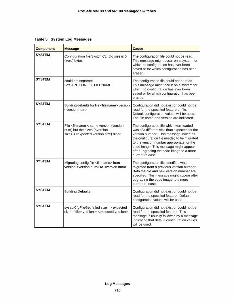
ProSafe M4100 and M7100 Managed Switches
Table 5. System Log Messages
Component Message Cause
SYSTEM Configuration file Switch CLI.cfg size is 0 (zero) bytes
The configuration file could not be read. This message might occur on a system for which no configuration has ever been saved or for which configuration has been erased.
SYSTEM could not separate SYSAPI_CONFIG_FILENAME
The configuration file could not be read. This message might occur on a system for which no configuration has ever been saved or for which configuration has been erased.
SYSTEM Building defaults for file <file name> version <version num>
Configuration did not exist or could not be read for the specified feature or file. Default configuration values will be used. The file name and version are indicated.
SYSTEM File <filename>: same version (version num) but the sizes (<version size>-><expected version size) differ
The configuration file which was loaded was of a different size than expected for the version number. This message indicates the configuration file needed to be migrated to the version number appropriate for the code image. This message might appear after upgrading the code image to a more current release.
SYSTEM Migrating config file <filename> from version <version num> to <version num>
The configuration file identified was migrated from a previous version number. Both the old and new version number are specified. This message might appear after upgrading the code image to a more current release.
SYSTEM Building Defaults Configuration did not exist or could not be read for the specified feature. Default configuration values will be used.
SYSTEM sysapiCfgFileGet failed size = <expected size of file> version = <expected version>
Configuration did not exist or could not be read for the specified feature. This message is usually followed by a message indicating that default configuration values will be used.
Log Messages
710
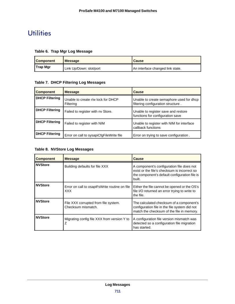
ProSafe M4100 and M7100 Managed Switches
Utilities
Table 6. Trap Mgr Log Message
Component Message Cause
Trap Mgr Link Up/Down: slot/port An interface changed link state.
Table 7. DHCP Filtering Log Messages
Component Message Cause
DHCP Filtering Unable to create r/w lock for DHCP Filtering
Unable to create semaphore used for dhcp filtering configuration structure .
DHCP Filtering Failed to register with nv Store. Unable to register save and restore functions for configuration save
DHCP Filtering Failed to register with NIM Unable to register with NIM for interface callback functions
DHCP Filtering Error on call to sysapiCfgFileWrite file Error on trying to save configuration .
Table 8. NVStore Log Messages
Component Message Cause
NVStore Building defaults for file XXX A component’s configuration file does not exist or the file’s checksum is incorrect so the component’s default configuration file is built.
NVStore Error on call to osapiFsWrite routine on file XXX
Either the file cannot be opened or the OS’s file I/O returned an error trying to write to the file.
NVStore File XXX corrupted from file system. Checksum mismatch.
The calculated checksum of a component’s configuration file in the file system did not match the checksum of the file in memory.
NVStore Migrating config file XXX from version Y to Z
A configuration file version mismatch was detected so a configuration file migration has started.
Log Messages
711
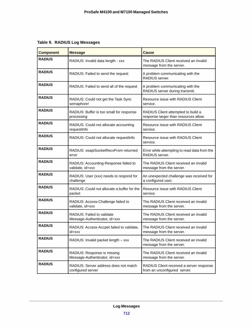
ProSafe M4100 and M7100 Managed Switches
Table 9. RADIUS Log Messages
Component Message Cause
RADIUS RADIUS: Invalid data length - xxx The RADIUS Client received an invalid message from the server.
RADIUS RADIUS: Failed to send the request A problem communicating with the RADIUS server.
RADIUS RADIUS: Failed to send all of the request A problem communicating with the RADIUS server during transmit.
RADIUS RADIUS: Could not get the Task Sync semaphore!
Resource issue with RADIUS Client service.
RADIUS RADIUS: Buffer is too small for response processing
RADIUS Client attempted to build a response larger than resources allow.
RADIUS RADIUS: Could not allocate accounting requestInfo
Resource issue with RADIUS Client service.
RADIUS RADIUS: Could not allocate requestInfo Resource issue with RADIUS Client service.
RADIUS RADIUS: osapiSocketRecvFrom returned error
Error while attempting to read data from the RADIUS server.
RADIUS RADIUS: Accounting-Response failed to validate, id=xxx
The RADIUS Client received an invalid message from the server.
RADIUS RADIUS: User (xxx) needs to respond for challenge
An unexpected challenge was received for a configured user.
RADIUS RADIUS: Could not allocate a buffer for the packet
Resource issue with RADIUS Client service.
RADIUS RADIUS: Access-Challenge failed to validate, id=xxx
The RADIUS Client received an invalid message from the server.
RADIUS RADIUS: Failed to validate Message-Authenticator, id=xxx
The RADIUS Client received an invalid message from the server.
RADIUS RADIUS: Access-Accpet failed to validate, id=xxx
The RADIUS Client received an invalid message from the server.
RADIUS RADIUS: Invalid packet length – xxx The RADIUS Client received an invalid message from the server.
RADIUS RADIUS: Response is missing Message-Authenticator, id=xxx
The RADIUS Client received an invalid message from the server.
RADIUS RADIUS: Server address does not match configured server
RADIUS Client received a server response from an unconfigured server.
Log Messages
712
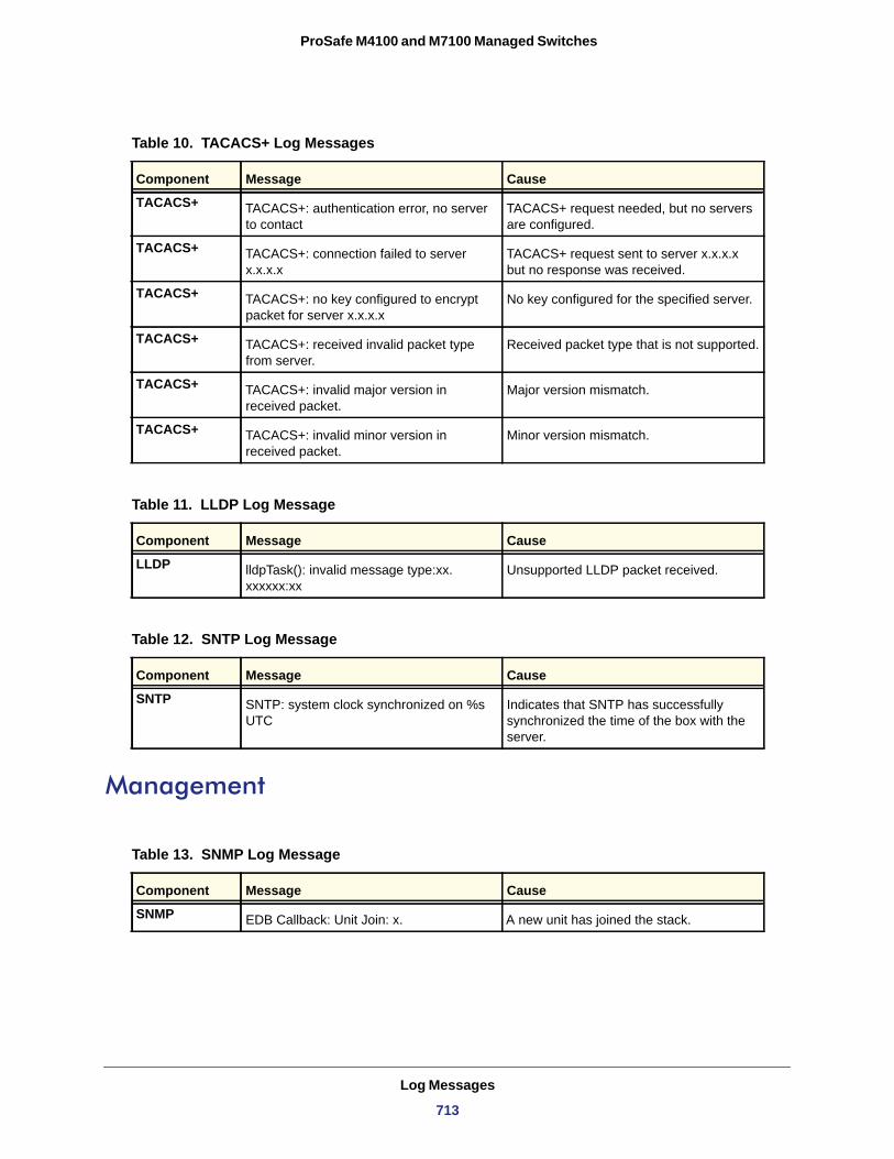
ProSafe M4100 and M7100 Managed Switches
Management
Table 10. TACACS+ Log Messages
Component Message Cause
TACACS+ TACACS+: authentication error, no server to contact
TACACS+ request needed, but no servers are configured.
TACACS+ TACACS+: connection failed to server x.x.x.x
TACACS+ request sent to server x.x.x.x but no response was received.
TACACS+ TACACS+: no key configured to encrypt packet for server x.x.x.x
No key configured for the specified server.
TACACS+ TACACS+: received invalid packet type from server.
Received packet type that is not supported.
TACACS+ TACACS+: invalid major version in received packet.
Major version mismatch.
TACACS+ TACACS+: invalid minor version in received packet.
Minor version mismatch.
Table 11. LLDP Log Message
Component Message Cause
LLDP lldpTask(): invalid message type:xx. xxxxxx:xx
Unsupported LLDP packet received.
Table 12. SNTP Log Message
Component Message Cause
SNTP SNTP: system clock synchronized on %s UTC
Indicates that SNTP has successfully synchronized the time of the box with the server.
Table 13. SNMP Log Message
Component Message Cause
SNMP EDB Callback: Unit Join: x. A new unit has joined the stack.
Log Messages
713
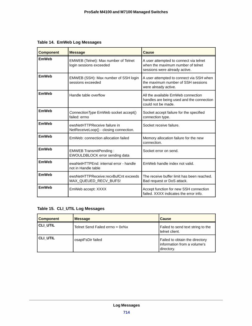
ProSafe M4100 and M7100 Managed Switches
Table 14. EmWeb Log Messages
Component Message Cause
EmWeb EMWEB (Telnet): Max number of Telnet login sessions exceeded
A user attempted to connect via telnet when the maximum number of telnet sessions were already active.
EmWeb EMWEB (SSH): Max number of SSH login sessions exceeded
A user attempted to connect via SSH when the maximum number of SSH sessions were already active.
EmWeb Handle table overflow All the available EmWeb connection handles are being used and the connection could not be made.
EmWeb ConnectionType EmWeb socket accept() failed: errno
Socket accept failure for the specified connection type.
EmWeb ewsNetHTTPReceive failure in NetReceiveLoop() - closing connection.
Socket receive failure.
EmWeb EmWeb: connection allocation failed Memory allocation failure for the new connection.
EmWeb EMWEB TransmitPending : EWOULDBLOCK error sending data
Socket error on send.
EmWeb ewaNetHTTPEnd: internal error - handle not in Handle table
EmWeb handle index not valid.
EmWeb ewsNetHTTPReceive:recvBufCnt exceeds MAX_QUEUED_RECV_BUFS!
The receive buffer limit has been reached. Bad request or DoS attack.
EmWeb EmWeb accept: XXXX Accept function for new SSH connection failed. XXXX indicates the error info.
Table 15. CLI_UTIL Log Messages
Component Message Cause
CLI_UTIL Telnet Send Failed errno = 0x%x Failed to send text string to the telnet client.
CLI_UTIL osapiFsDir failed Failed to obtain the directory information from a volume's directory.
Log Messages
714
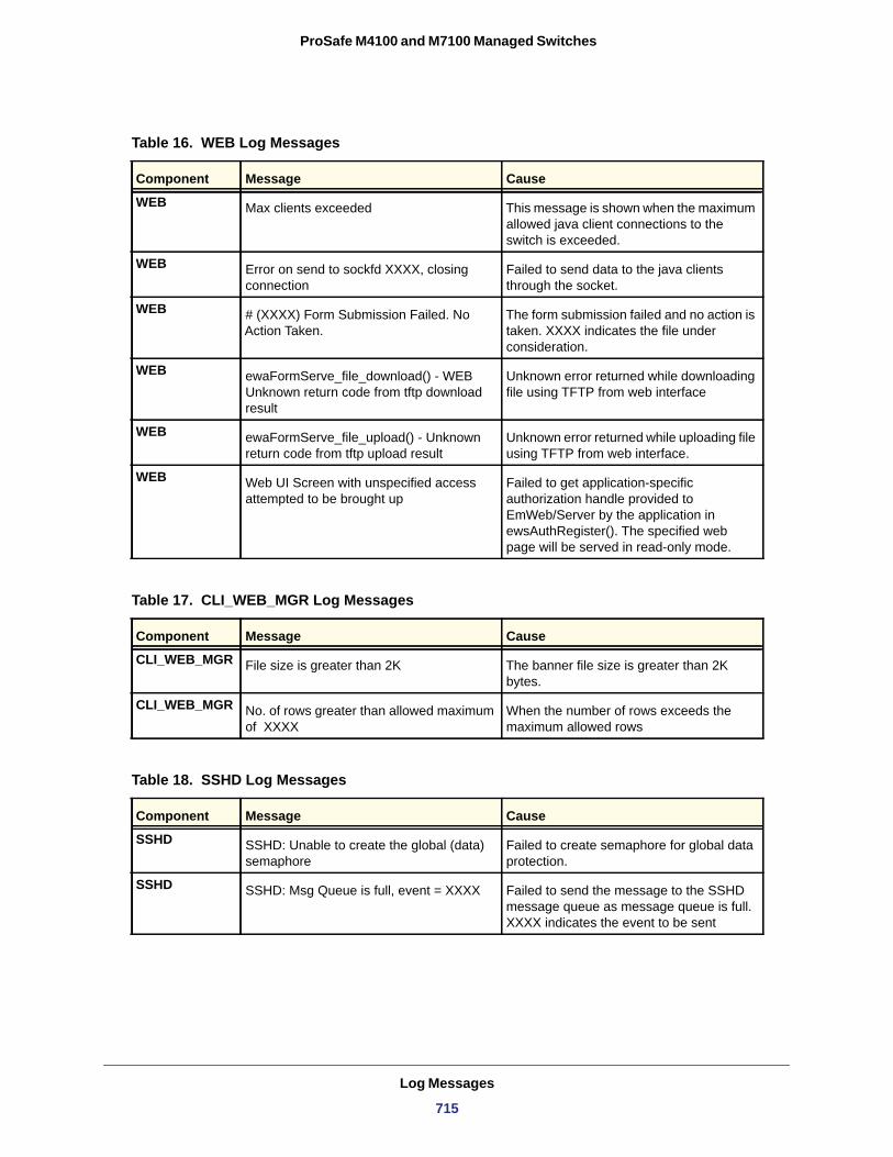
ProSafe M4100 and M7100 Managed Switches
Table 16. WEB Log Messages
Component Message Cause
WEB Max clients exceeded This message is shown when the maximum allowed java client connections to the switch is exceeded.
WEB Error on send to sockfd XXXX, closing connection
Failed to send data to the java clients through the socket.
WEB # (XXXX) Form Submission Failed. No Action Taken.
The form submission failed and no action is taken. XXXX indicates the file under consideration.
WEB ewaFormServe_file_download() - WEB Unknown return code from tftp download result
Unknown error returned while downloading file using TFTP from web interface
WEB ewaFormServe_file_upload() - Unknown return code from tftp upload result
Unknown error returned while uploading file using TFTP from web interface.
WEB Web UI Screen with unspecified access attempted to be brought up
Failed to get application-specific authorization handle provided to EmWeb/Server by the application in ewsAuthRegister(). The specified web page will be served in read-only mode.
Table 17. CLI_WEB_MGR Log Messages
Component Message Cause
CLI_WEB_MGR File size is greater than 2K The banner file size is greater than 2K bytes.
CLI_WEB_MGR No. of rows greater than allowed maximum of XXXX
When the number of rows exceeds the maximum allowed rows
Table 18. SSHD Log Messages
Component Message Cause
SSHD SSHD: Unable to create the global (data) semaphore
Failed to create semaphore for global data protection.
SSHD SSHD: Msg Queue is full, event = XXXX Failed to send the message to the SSHD message queue as message queue is full. XXXX indicates the event to be sent
Log Messages
715
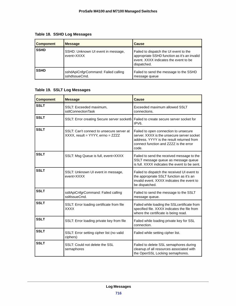
ProSafe M4100 and M7100 Managed Switches
SSHD SSHD: Unknown UI event in message, event=XXXX
Failed to dispatch the UI event to the appropriate SSHD function as it’s an invalid event. XXXX indicates the event to be dispatched.
SSHD sshdApiCnfgrCommand: Failed calling sshdIssueCmd.
Failed to send the message to the SSHD message queue
Table 19. SSLT Log Messages
Component Message Cause
SSLT SSLT: Exceeded maximum, ssltConnectionTask
Exceeded maximum allowed SSLT connections.
SSLT SSLT: Error creating Secure server socket6 Failed to create secure server socket for IPV6.
SSLT SSLT: Can't connect to unsecure server at XXXX, result = YYYY, errno = ZZZZ
Failed to open connection to unsecure server. XXXX is the unsecure server socket address. YYYY is the result returned from connect function and ZZZZ is the error code.
SSLT SSLT: Msg Queue is full, event=XXXX Failed to send the received message to the SSLT message queue as message queue is full. XXXX indicates the event to be sent.
SSLT SSLT: Unknown UI event in message, event=XXXX
Failed to dispatch the received UI event to the appropriate SSLT function as it’s an invalid event. XXXX indicates the event to be dispatched.
SSLT ssltApiCnfgrCommand: Failed calling ssltIssueCmd.
Failed to send the message to the SSLT message queue.
SSLT SSLT: Error loading certificate from file XXXX
Failed while loading the SSLcertificate from specified file. XXXX indicates the file from where the certificate is being read.
SSLT SSLT: Error loading private key from file Failed while loading private key for SSL connection.
SSLT SSLT: Error setting cipher list (no valid ciphers)
Failed while setting cipher list.
SSLT SSLT: Could not delete the SSL semaphores
Failed to delete SSL semaphores during cleanup.of all resources associated with the OpenSSL Locking semaphores.
Table 18. SSHD Log Messages
Component Message Cause
Log Messages
716
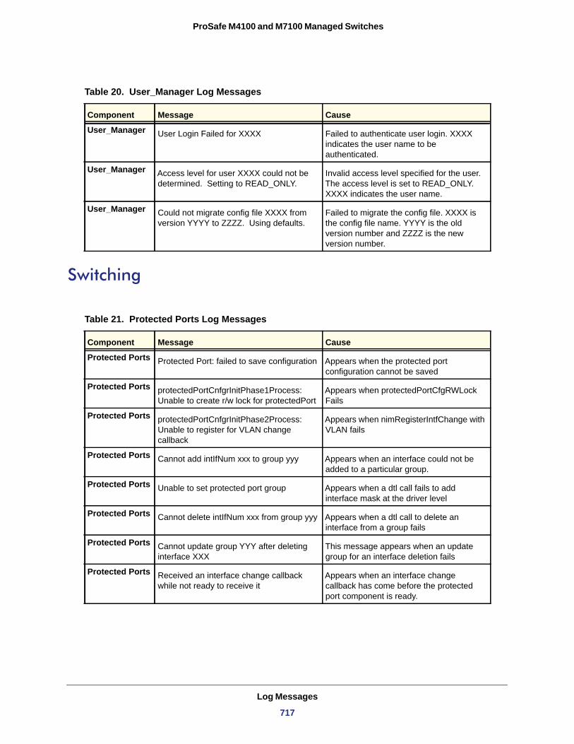
ProSafe M4100 and M7100 Managed Switches
Switching
Table 20. User_Manager Log Messages
Component Message Cause
User_Manager User Login Failed for XXXX Failed to authenticate user login. XXXX indicates the user name to be authenticated.
User_Manager Access level for user XXXX could not be determined. Setting to READ_ONLY.
Invalid access level specified for the user. The access level is set to READ_ONLY. XXXX indicates the user name.
User_Manager Could not migrate config file XXXX from version YYYY to ZZZZ. Using defaults.
Failed to migrate the config file. XXXX is the config file name. YYYY is the old version number and ZZZZ is the new version number.
Table 21. Protected Ports Log Messages
Component Message Cause
Protected Ports Protected Port: failed to save configuration Appears when the protected port configuration cannot be saved
Protected Ports protectedPortCnfgrInitPhase1Process: Unable to create r/w lock for protectedPort
Appears when protectedPortCfgRWLock Fails
Protected Ports protectedPortCnfgrInitPhase2Process: Unable to register for VLAN change callback
Appears when nimRegisterIntfChange with VLAN fails
Protected Ports Cannot add intIfNum xxx to group yyy Appears when an interface could not be added to a particular group.
Protected Ports Unable to set protected port group Appears when a dtl call fails to add interface mask at the driver level
Protected Ports Cannot delete intIfNum xxx from group yyy Appears when a dtl call to delete an interface from a group fails
Protected Ports Cannot update group YYY after deleting interface XXX
This message appears when an update group for an interface deletion fails
Protected Ports Received an interface change callback while not ready to receive it
Appears when an interface change callback has come before the protected port component is ready.
Log Messages
717
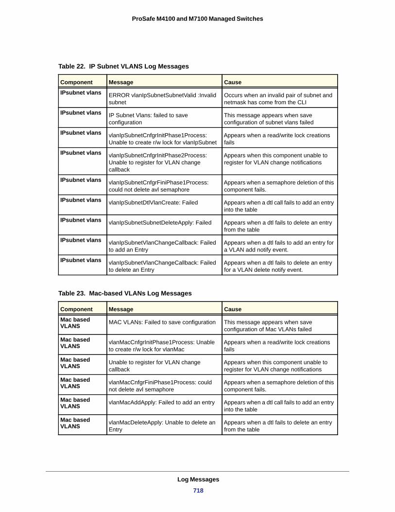
ProSafe M4100 and M7100 Managed Switches
Table 22. IP Subnet VLANS Log Messages
Component Message Cause
IPsubnet vlans ERROR vlanIpSubnetSubnetValid :Invalid subnet
Occurs when an invalid pair of subnet and netmask has come from the CLI
IPsubnet vlans IP Subnet Vlans: failed to save configuration
This message appears when save configuration of subnet vlans failed
IPsubnet vlans vlanIpSubnetCnfgrInitPhase1Process: Unable to create r/w lock for vlanIpSubnet
Appears when a read/write lock creations fails
IPsubnet vlans vlanIpSubnetCnfgrInitPhase2Process: Unable to register for VLAN change callback
Appears when this component unable to register for VLAN change notifications
IPsubnet vlans vlanIpSubnetCnfgrFiniPhase1Process: could not delete avl semaphore
Appears when a semaphore deletion of this component fails.
IPsubnet vlans vlanIpSubnetDtlVlanCreate: Failed Appears when a dtl call fails to add an entry into the table
IPsubnet vlans vlanIpSubnetSubnetDeleteApply: Failed Appears when a dtl fails to delete an entry from the table
IPsubnet vlans vlanIpSubnetVlanChangeCallback: Failed to add an Entry
Appears when a dtl fails to add an entry for a VLAN add notify event.
IPsubnet vlans vlanIpSubnetVlanChangeCallback: Failed to delete an Entry
Appears when a dtl fails to delete an entry for a VLAN delete notify event.
Table 23. Mac-based VLANs Log Messages
Component Message Cause
Mac based VLANS MAC VLANs: Failed to save configuration This message appears when save
configuration of Mac VLANs failed
Mac based VLANS vlanMacCnfgrInitPhase1Process: Unable
to create r/w lock for vlanMacAppears when a read/write lock creations fails
Mac based VLANS Unable to register for VLAN change
callbackAppears when this component unable to register for VLAN change notifications
Mac based VLANS vlanMacCnfgrFiniPhase1Process: could
not delete avl semaphoreAppears when a semaphore deletion of this component fails.
Mac based VLANS vlanMacAddApply: Failed to add an entry Appears when a dtl call fails to add an entry
into the table
Mac based VLANS vlanMacDeleteApply: Unable to delete an
EntryAppears when a dtl fails to delete an entry from the table
Log Messages
718
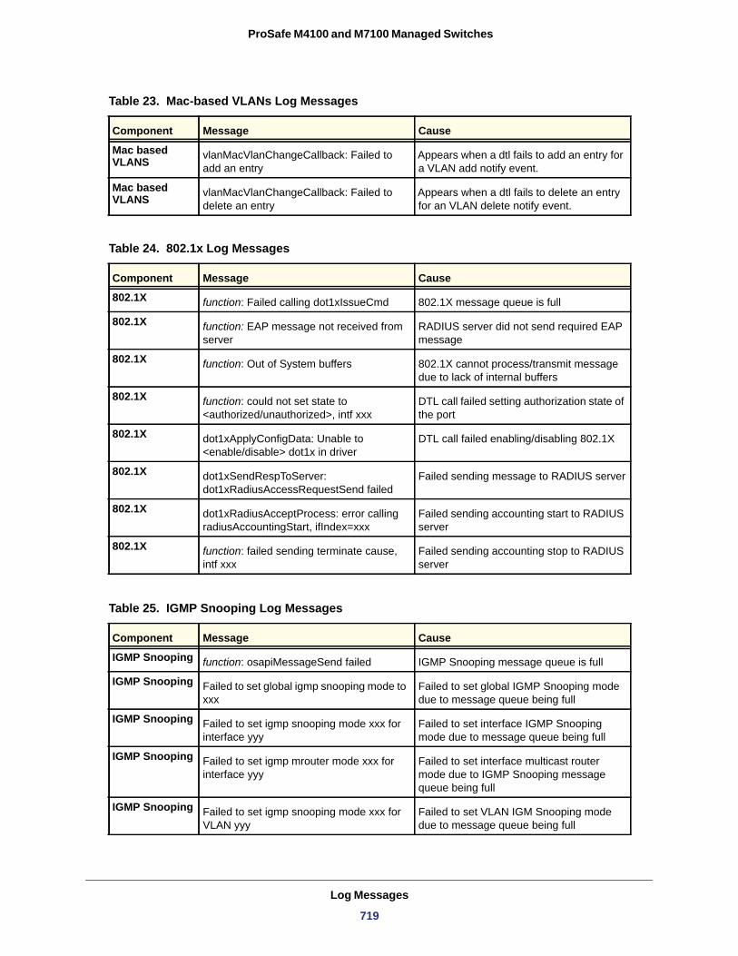
ProSafe M4100 and M7100 Managed Switches
Mac based VLANS vlanMacVlanChangeCallback: Failed to
add an entryAppears when a dtl fails to add an entry for a VLAN add notify event.
Mac based VLANS vlanMacVlanChangeCallback: Failed to
delete an entryAppears when a dtl fails to delete an entry for an VLAN delete notify event.
Table 24. 802.1x Log Messages
Component Message Cause
802.1X function: Failed calling dot1xIssueCmd 802.1X message queue is full
802.1X function: EAP message not received from server
RADIUS server did not send required EAP message
802.1X function: Out of System buffers 802.1X cannot process/transmit message due to lack of internal buffers
802.1X function: could not set state to <authorized/unauthorized>, intf xxx
DTL call failed setting authorization state of the port
802.1X dot1xApplyConfigData: Unable to <enable/disable> dot1x in driver
DTL call failed enabling/disabling 802.1X
802.1X dot1xSendRespToServer: dot1xRadiusAccessRequestSend failed
Failed sending message to RADIUS server
802.1X dot1xRadiusAcceptProcess: error calling radiusAccountingStart, ifIndex=xxx
Failed sending accounting start to RADIUS server
802.1X function: failed sending terminate cause, intf xxx
Failed sending accounting stop to RADIUS server
Table 25. IGMP Snooping Log Messages
Component Message Cause
IGMP Snooping function: osapiMessageSend failed IGMP Snooping message queue is full
IGMP Snooping Failed to set global igmp snooping mode to xxx
Failed to set global IGMP Snooping mode due to message queue being full
IGMP Snooping Failed to set igmp snooping mode xxx for interface yyy
Failed to set interface IGMP Snooping mode due to message queue being full
IGMP Snooping Failed to set igmp mrouter mode xxx for interface yyy
Failed to set interface multicast router mode due to IGMP Snooping message queue being full
IGMP Snooping Failed to set igmp snooping mode xxx for VLAN yyy
Failed to set VLAN IGM Snooping mode due to message queue being full
Table 23. Mac-based VLANs Log Messages
Component Message Cause
Log Messages
719
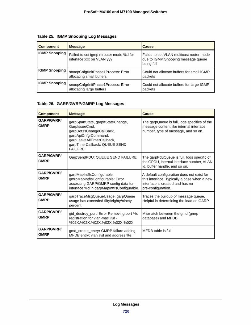
ProSafe M4100 and M7100 Managed Switches
IGMP Snooping Failed to set igmp mrouter mode %d for interface xxx on VLAN yyy
Failed to set VLAN multicast router mode due to IGMP Snooping message queue being full
IGMP Snooping snoopCnfgrInitPhase1Process: Error allocating small buffers
Could not allocate buffers for small IGMP packets
IGMP Snooping snoopCnfgrInitPhase1Process: Error allocating large buffers
Could not allocate buffers for large IGMP packets
Table 26. GARP/GVRP/GMRP Log Messages
Component Message Cause
GARP/GVRP/GMRP
garpSpanState, garpIfStateChange, GarpIssueCmd, garpDot1sChangeCallBack, garpApiCnfgrCommand, garpLeaveAllTimerCallback, garpTimerCallback: QUEUE SEND FAILURE:
The garpQueue is full, logs specifics of the message content like internal interface number, type of message, and so on.
GARP/GVRP/GMRP
GarpSendPDU: QUEUE SEND FAILURE The garpPduQueue is full, logs specific of the GPDU, internal interface number, VLAN id, buffer handle, and so on.
GARP/GVRP/GMRP
garpMapIntfIsConfigurable, gmrpMapIntfIsConfigurable: Error accessing GARP/GMRP config data for interface %d in garpMapIntfIsConfigurable.
A default configuration does not exist for this interface. Typically a case when a new interface is created and has no pre-configuration.
GARP/GVRP/GMRP
garpTraceMsgQueueUsage: garpQueue usage has exceeded fifty/eighty/ninety percent
Traces the buildup of message queue. Helpful in determining the load on GARP.
GARP/GVRP/GMRP
gid_destroy_port: Error Removing port %d registration for vlan-mac %d - %02X:%02X:%02X:%02X:%02X:%02X
Mismatch between the gmd (gmrp database) and MFDB.
GARP/GVRP/GMRP
gmd_create_entry: GMRP failure adding MFDB entry: vlan %d and address %s
MFDB table is full.
Table 25. IGMP Snooping Log Messages
Component Message Cause
Log Messages
720
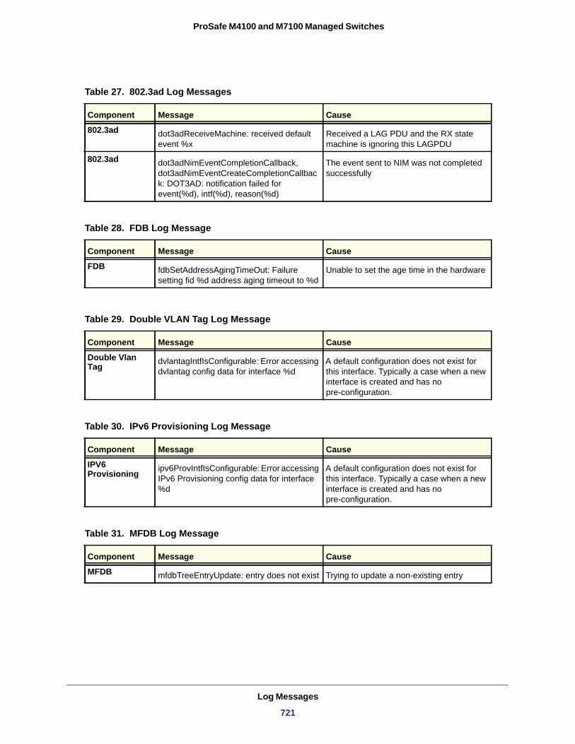
ProSafe M4100 and M7100 Managed Switches
Table 27. 802.3ad Log Messages
Component Message Cause
802.3ad dot3adReceiveMachine: received default event %x
Received a LAG PDU and the RX state machine is ignoring this LAGPDU
802.3ad dot3adNimEventCompletionCallback, dot3adNimEventCreateCompletionCallback: DOT3AD: notification failed for event(%d), intf(%d), reason(%d)
The event sent to NIM was not completed successfully
Table 28. FDB Log Message
Component Message Cause
FDB fdbSetAddressAgingTimeOut: Failure setting fid %d address aging timeout to %d
Unable to set the age time in the hardware
Table 29. Double VLAN Tag Log Message
Component Message Cause
Double Vlan Tag dvlantagIntfIsConfigurable: Error accessing
dvlantag config data for interface %dA default configuration does not exist for this interface. Typically a case when a new interface is created and has no pre-configuration.
Table 30. IPv6 Provisioning Log Message
Component Message Cause
IPV6 Provisioning ipv6ProvIntfIsConfigurable: Error accessing
IPv6 Provisioning config data for interface %d
A default configuration does not exist for this interface. Typically a case when a new interface is created and has no pre-configuration.
Table 31. MFDB Log Message
Component Message Cause
MFDB mfdbTreeEntryUpdate: entry does not exist Trying to update a non-existing entry
Log Messages
721
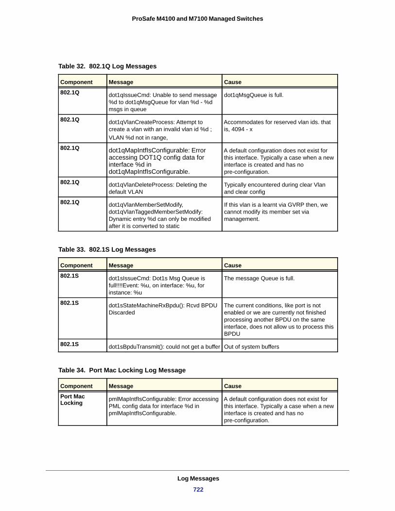
ProSafe M4100 and M7100 Managed Switches
Table 32. 802.1Q Log Messages
Component Message Cause
802.1Q dot1qIssueCmd: Unable to send message %d to dot1qMsgQueue for vlan %d - %d msgs in queue
dot1qMsgQueue is full.
802.1Q dot1qVlanCreateProcess: Attempt to create a vlan with an invalid vlan id %d ;VLAN %d not in range,
Accommodates for reserved vlan ids. that is, 4094 - x
802.1Q dot1qMapIntfIsConfigurable: Error accessing DOT1Q config data for interface %d in dot1qMapIntfIsConfigurable.
A default configuration does not exist for this interface. Typically a case when a new interface is created and has no pre-configuration.
802.1Q dot1qVlanDeleteProcess: Deleting the default VLAN
Typically encountered during clear Vlan and clear config
802.1Q dot1qVlanMemberSetModify, dot1qVlanTaggedMemberSetModify: Dynamic entry %d can only be modified after it is converted to static
If this vlan is a learnt via GVRP then, we cannot modify its member set via management.
Table 33. 802.1S Log Messages
Component Message Cause
802.1S dot1sIssueCmd: Dot1s Msg Queue is full!!!!Event: %u, on interface: %u, for instance: %u
The message Queue is full.
802.1S dot1sStateMachineRxBpdu(): Rcvd BPDU Discarded
The current conditions, like port is not enabled or we are currently not finished processing another BPDU on the same interface, does not allow us to process this BPDU
802.1S dot1sBpduTransmit(): could not get a buffer Out of system buffers
Table 34. Port Mac Locking Log Message
Component Message Cause
Port Mac Locking pmlMapIntfIsConfigurable: Error accessing
PML config data for interface %d in pmlMapIntfIsConfigurable.
A default configuration does not exist for this interface. Typically a case when a new interface is created and has no pre-configuration.
Log Messages
722
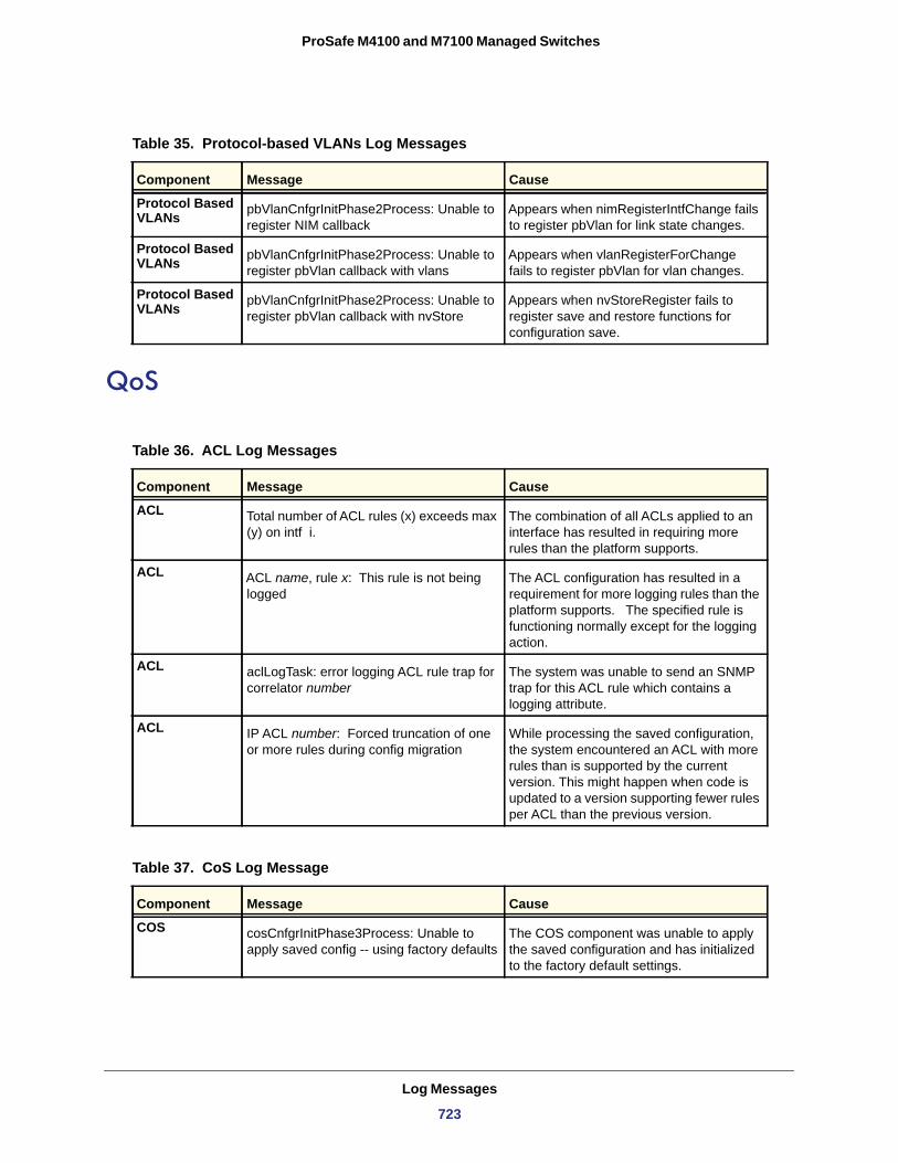
ProSafe M4100 and M7100 Managed Switches
QoS
Table 35. Protocol-based VLANs Log Messages
Component Message Cause
Protocol Based VLANs pbVlanCnfgrInitPhase2Process: Unable to
register NIM callbackAppears when nimRegisterIntfChange fails to register pbVlan for link state changes.
Protocol Based VLANs pbVlanCnfgrInitPhase2Process: Unable to
register pbVlan callback with vlansAppears when vlanRegisterForChange fails to register pbVlan for vlan changes.
Protocol Based VLANs pbVlanCnfgrInitPhase2Process: Unable to
register pbVlan callback with nvStoreAppears when nvStoreRegister fails to register save and restore functions for configuration save.
Table 36. ACL Log Messages
Component Message Cause
ACL Total number of ACL rules (x) exceeds max (y) on intf i.
The combination of all ACLs applied to an interface has resulted in requiring more rules than the platform supports.
ACL ACL name, rule x: This rule is not being logged
The ACL configuration has resulted in a requirement for more logging rules than the platform supports. The specified rule is functioning normally except for the logging action.
ACL aclLogTask: error logging ACL rule trap for correlator number
The system was unable to send an SNMP trap for this ACL rule which contains a logging attribute.
ACL IP ACL number: Forced truncation of one or more rules during config migration
While processing the saved configuration, the system encountered an ACL with more rules than is supported by the current version. This might happen when code is updated to a version supporting fewer rules per ACL than the previous version.
Table 37. CoS Log Message
Component Message Cause
COS cosCnfgrInitPhase3Process: Unable to apply saved config -- using factory defaults
The COS component was unable to apply the saved configuration and has initialized to the factory default settings.
Log Messages
723
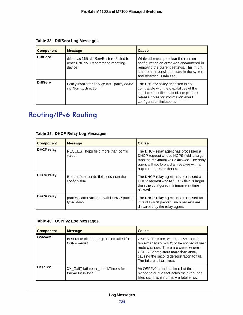
ProSafe M4100 and M7100 Managed Switches
Routing/IPv6 Routing
Table 38. DiffServ Log Messages
Component Message Cause
DiffServ diffserv.c 165: diffServRestore Failed to reset DiffServ. Recommend resetting device
While attempting to clear the running configuration an error was encountered in removing the current settings. This might lead to an inconsistent state in the system and resetting is advised.
DiffServ Policy invalid for service intf: "policy name, intIfNum x, direction y
The DiffServ policy definition is not compatible with the capabilities of the interface specified. Check the platform release notes for information about configuration limitations.
Table 39. DHCP Relay Log Messages
Component Message Cause
DHCP relay REQUEST hops field more than config value
The DHCP relay agent has processed a DHCP request whose HOPS field is larger than the maximum value allowed. The relay agent will not forward a message with a hop count greater than 4.
DHCP relay Request's seconds field less than the config value
The DHCP relay agent has processed a DHCP request whose SECS field is larger than the configured minimum wait time allowed.
DHCP relay processDhcpPacket: invalid DHCP packet type: %u\n
The DHCP relay agent has processed an invalid DHCP packet. Such packets are discarded by the relay agent.
Table 40. OSPFv2 Log Messages
Component Message Cause
OSPFv2 Best route client deregistration failed for OSPF Redist
OSPFv2 registers with the IPv4 routing table manager (“RTO”) to be notified of best route changes. There are cases where OSPFv2 deregisters more than once, causing the second deregistration to fail. The failure is harmless.
OSPFv2 XX_Call() failure in _checkTimers for thread 0x869bcc0
An OSPFv2 timer has fired but the message queue that holds the event has filled up. This is normally a fatal error.
Log Messages
724
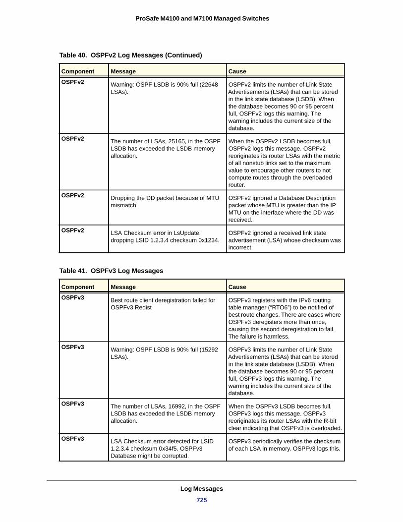
ProSafe M4100 and M7100 Managed Switches
OSPFv2 Warning: OSPF LSDB is 90% full (22648 LSAs).
OSPFv2 limits the number of Link State Advertisements (LSAs) that can be stored in the link state database (LSDB). When the database becomes 90 or 95 percent full, OSPFv2 logs this warning. The warning includes the current size of the database.
OSPFv2 The number of LSAs, 25165, in the OSPF LSDB has exceeded the LSDB memory allocation.
When the OSPFv2 LSDB becomes full, OSPFv2 logs this message. OSPFv2 reoriginates its router LSAs with the metric of all nonstub links set to the maximum value to encourage other routers to not compute routes through the overloaded router.
OSPFv2 Dropping the DD packet because of MTU mismatch
OSPFv2 ignored a Database Description packet whose MTU is greater than the IP MTU on the interface where the DD was received.
OSPFv2 LSA Checksum error in LsUpdate, dropping LSID 1.2.3.4 checksum 0x1234.
OSPFv2 ignored a received link state advertisement (LSA) whose checksum was incorrect.
Table 41. OSPFv3 Log Messages
Component Message Cause
OSPFv3 Best route client deregistration failed for OSPFv3 Redist
OSPFv3 registers with the IPv6 routing table manager (“RTO6”) to be notified of best route changes. There are cases where OSPFv3 deregisters more than once, causing the second deregistration to fail. The failure is harmless.
OSPFv3 Warning: OSPF LSDB is 90% full (15292 LSAs).
OSPFv3 limits the number of Link State Advertisements (LSAs) that can be stored in the link state database (LSDB). When the database becomes 90 or 95 percent full, OSPFv3 logs this warning. The warning includes the current size of the database.
OSPFv3 The number of LSAs, 16992, in the OSPF LSDB has exceeded the LSDB memory allocation.
When the OSPFv3 LSDB becomes full, OSPFv3 logs this message. OSPFv3 reoriginates its router LSAs with the R-bit clear indicating that OSPFv3 is overloaded.
OSPFv3 LSA Checksum error detected for LSID 1.2.3.4 checksum 0x34f5. OSPFv3 Database might be corrupted.
OSPFv3 periodically verifies the checksum of each LSA in memory. OSPFv3 logs this.
Table 40. OSPFv2 Log Messages (Continued)
Component Message Cause
Log Messages
725
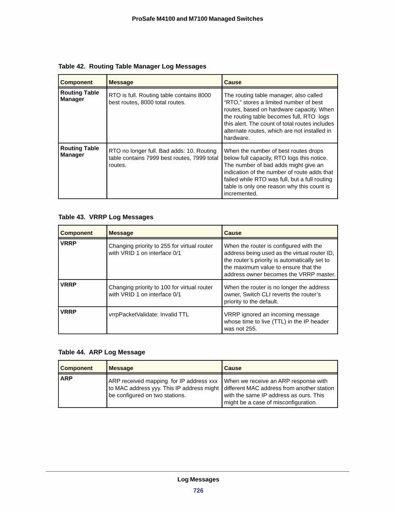
ProSafe M4100 and M7100 Managed Switches
Table 42. Routing Table Manager Log Messages
Component Message Cause
Routing Table Manager RTO is full. Routing table contains 8000
best routes, 8000 total routes.The routing table manager, also called “RTO,” stores a limited number of best routes, based on hardware capacity. When the routing table becomes full, RTO logs this alert. The count of total routes includes alternate routes, which are not installed in hardware.
Routing Table Manager RTO no longer full. Bad adds: 10. Routing
table contains 7999 best routes, 7999 total routes.
When the number of best routes drops below full capacity, RTO logs this notice. The number of bad adds might give an indication of the number of route adds that failed while RTO was full, but a full routing table is only one reason why this count is incremented.
Table 43. VRRP Log Messages
Component Message Cause
VRRP Changing priority to 255 for virtual router with VRID 1 on interface 0/1
When the router is configured with the address being used as the virtual router ID, the router’s priority is automatically set to the maximum value to ensure that the address owner becomes the VRRP master.
VRRP Changing priority to 100 for virtual router with VRID 1 on interface 0/1
When the router is no longer the address owner, Switch CLI reverts the router’s priority to the default.
VRRP vrrpPacketValidate: Invalid TTL VRRP ignored an incoming message whose time to live (TTL) in the IP header was not 255.
Table 44. ARP Log Message
Component Message Cause
ARP ARP received mapping for IP address xxx to MAC address yyy. This IP address might be configured on two stations.
When we receive an ARP response with different MAC address from another station with the same IP address as ours. This might be a case of misconfiguration.
Log Messages
726
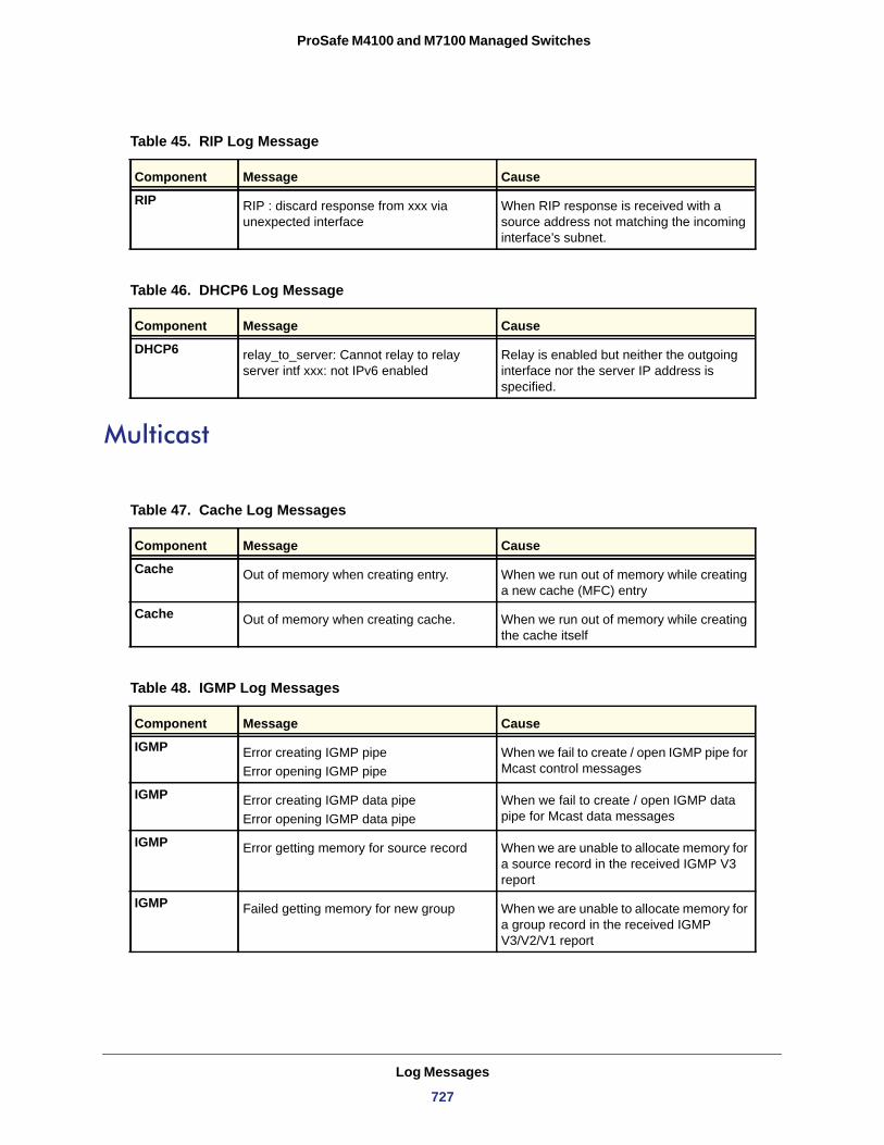
ProSafe M4100 and M7100 Managed Switches
Multicast
Table 45. RIP Log Message
Component Message Cause
RIP RIP : discard response from xxx via unexpected interface
When RIP response is received with a source address not matching the incoming interface’s subnet.
Table 46. DHCP6 Log Message
Component Message Cause
DHCP6 relay_to_server: Cannot relay to relay server intf xxx: not IPv6 enabled
Relay is enabled but neither the outgoing interface nor the server IP address is specified.
Table 47. Cache Log Messages
Component Message Cause
Cache Out of memory when creating entry. When we run out of memory while creating a new cache (MFC) entry
Cache Out of memory when creating cache. When we run out of memory while creating the cache itself
Table 48. IGMP Log Messages
Component Message Cause
IGMP Error creating IGMP pipeError opening IGMP pipe
When we fail to create / open IGMP pipe for Mcast control messages
IGMP Error creating IGMP data pipeError opening IGMP data pipe
When we fail to create / open IGMP data pipe for Mcast data messages
IGMP Error getting memory for source record When we are unable to allocate memory for a source record in the received IGMP V3 report
IGMP Failed getting memory for new group When we are unable to allocate memory for a group record in the received IGMP V3/V2/V1 report
Log Messages
727
ProSafe M4100 and M7100 Managed Switches
Table 49. IGMP-Proxy Log Messages
Component Message Cause
IGMP-Proxy Error getting memory for igmp host group record
When we are unable to allocate memory for the IGMP group record in the Host (Proxy) table
IGMP-Proxy Error getting memory for source record When we are unable to allocate memory for the IGMP source record in the Host (Proxy) table
Table 50. PIM-SM Log Messages
Component Message Cause
PIM-SM PIM-SM not initialized This message arises when trying to activate pimsm interfaces or receiving pimsm packets when pimsm component is not initialized.
PIM-SM Unable to take xxx semaphore This message is logged when failed to acquire semaphore to access source list or group list or candidate Rp list or virtual interface list. The xxx specifies the list for which the access is denied.
PIM-SM Warning : Could not send packet type xxx (pimsm packet type) on rtrIfNum
this warning is logged when failed to send a pimsm control packet on the specified router interface.
PIM-SM add_kernel_cache : memory allocation failed
This message is logged when there is insufficient memory to add a mroute entry into cache.
PIM_SM Config error. Trying to add static RP. Dynamic RP with same ip addr exists
Router learns RP-group mapping through Bootstrap messages received.This message pops when the static RP is configured which conflicts the mapping learnt dynamically through Bootstrap messages.
PIM-SM Inner xxx(source/group) address of register message is invalid
This log message appears when a register message is received with invalid inner ip source or group address.
Log Messages
728
ProSafe M4100 and M7100 Managed Switches
Stacking
Table 51. PIM-DM Log Messages
Component Message Cause
PIM-DM Out of memory when creating xxx This message is logged when there is insufficient memory to accommodate a new neighbor/(S,G) Entry, Prune, Graft, Join etc.
PIM-DM Error entry->ll_xxx LL creation error This message is logged when the SLL creation is Failed.
PIM-DM pim_interface_set: Could not give taskSema
This message is logged when Task synchronization Semaphore release fails.
PIM-DM Error initializing CACHE This message is logged when the PIM-DM (S,G) entry Cache table initialization fails.
PIM-DM Error creating PIM-DM pipe This message is logged when the PIM-DM Pipe (that receives control messages) creation fails.
Table 52. DVMRP Log Messages
Component Message Cause
DVMRP dvmrp_send_graft: failed getting memory for graft
Failed to allocate memory while sending a graft
DVMRP dvmrp_register_neighbor: failed getting memory for nbr
Failed to allocate memory while registering a neighbor
DVMRP dvmrp_recv_prune: failed getting memory for prune
Failed to allocate memory while receiving a prune
DVMRP dvmrp_new_route: failed getting memory for route
Failed to get memory for a new route entry
DVMRP dvmrp_prepare_routes: failed getting memory for dvmrp_ann_rt
Failed to get memory while announcing a new route entry
Table 53. EDB Log Message
Component Message Cause
EDB EDB Callback: Unit Join: <num>. Unit <num> has joined the stack.
Log Messages
729
ProSafe M4100 and M7100 Managed Switches
Technologies
Table 54. System General Error Messages
Component Message Cause
OS Invalid USP unit = x, slot = x, port =x A port was not able to be translated correctly during the receive.
OS In hapiBroadSystemMacAddress call to 'bcm_l2_addr_add' - FAILED : x
Failed to add an L2 address to the MAC table. This should only happen when a hash collision occurs or the table is full.
OS Failed installing mirror action - rest of the policy applied successfully
A previously configured probe port is not being used in the policy. The release notes state that only a single probe port can be configured
OS Policy x does not contain rule x The rule was not added to the policy due to a discrepancy in the rule count for this specific policy . Additionally, the message can be displayed when an old rule is being modified, but the old rule is not in the policy
OS ERROR: policy x, tmpPolicy x, size x, data x x x x x x x x
An issue installing the policy due to a possible duplicate hash
OS ACL x not found in internal table Attempting to delete a non-existent ACL
OS ACL internal table overflow Attempting to add an ACL to a full table
OS In hapiBroadQosCosQueueConfig, Failed to configure minimum bandwidth. Available bandwidth x
Attempting to configure the bandwidth beyond its capabilities
OS USL: failed to put sync response on queue A response to a sync request was not enqueued. This could indicate that a previous sync request was received after it was timed out
OS USL: failed to sync ipmc table on unit=x Either the transport failed or the message was dropped
OS usl_task_ipmc_msg_send(): failed to send with x
Either the transport failed or the message was dropped
OS USL: No available entries in the STG table The Spanning Tree Group table is full in USL
OS USL: failed to sync stg table on unit=x Could not synchronize unit x due to a transport failure or API issue on remote unit. A synchronization retry will be issued
OS USL: A Trunk doesn't exist in USL Attempting to modify a Trunk that doesn’t exist
Log Messages
730
ProSafe M4100 and M7100 Managed Switches
OS USL: A Trunk being created by bcmx already existed in USL
Possible synchronization issue between the application, hardware, and sync layer
OS USL: A Trunk being destroyed doesn't exist in USL
Possible synchronization issue between the application, hardware, and sync layer.
OS USL: A Trunk being set doesn't exist in USL
Possible synchronization issue between the application, hardware, and sync layer.
OS USL: failed to sync trunk table on unit=x Could not synchronize unit x due to a transport failure or API issue on remote unit. A synchronization retry will be issued
OS USL: Mcast entry not found on a join Possible synchronization issue between the application, hardware, and sync layer
OS USL: Mcast entry not found on a leave Possible synchronization issue between the application, hardware, and sync layer
OS USL: failed to sync dvlan data on unit=x Could not synchronize unit x due to a transport failure or API issue on remote unit. A synchronization retry will be issued
OS USL: failed to sync policy table on unit=x Could not synchronize unit x due to a transport failure or API issue on remote unit. A synchronization retry will be issued
OS USL: failed to sync VLAN table on unit=x Could not synchronize unit x due to a transport failure or API issue on remote unit. A synchronization retry will be issued
OS Invalid LAG id x Possible synchronization issue between the BCM driver and HAPI
OS Invalid uport calculated from the BCM uport bcmx_l2_addr->lport = x
Uport not valid from BCM driver.
OS Invalid USP calculated from the BCM uport\nbcmx_l2_addr->lport = x
USP not able to be calculated from the learn event for BCM driver.
OS Unable to insert route R/P Route ‘R’ with prefix ‘P’ could not be inserted in the hardware route table. A retry will be issued.
OS Unable to Insert host H Host ‘H’ could not be inserted in hardware host table. A retry will be issued.
OS USL: failed to sync L3 Intf table on unit=x Could not synchronize unit x due to a transport failure or API issue on remote unit. A synchronization retry will be issued
OS USL: failed to sync L3 Host table on unit=x Could not synchronize unit x due to a transport failure or API issue on remote unit. A synchronization retry will be issued
Table 54. System General Error Messages
Component Message Cause
Log Messages
731
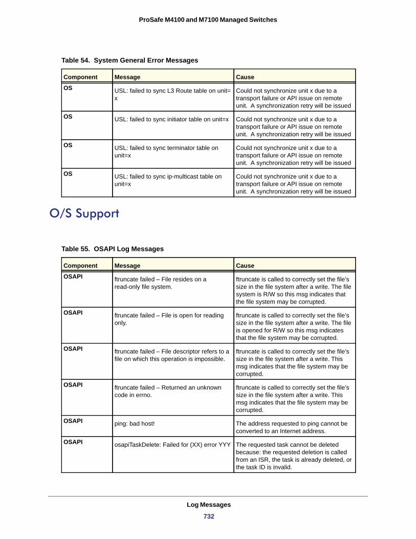
ProSafe M4100 and M7100 Managed Switches
O/S Support
OS USL: failed to sync L3 Route table on unit=x
Could not synchronize unit x due to a transport failure or API issue on remote unit. A synchronization retry will be issued
OS USL: failed to sync initiator table on unit=x Could not synchronize unit x due to a transport failure or API issue on remote unit. A synchronization retry will be issued
OS USL: failed to sync terminator table on unit=x
Could not synchronize unit x due to a transport failure or API issue on remote unit. A synchronization retry will be issued
OS USL: failed to sync ip-multicast table on unit=x
Could not synchronize unit x due to a transport failure or API issue on remote unit. A synchronization retry will be issued
Table 55. OSAPI Log Messages
Component Message Cause
OSAPI ftruncate failed – File resides on a read-only file system.
ftruncate is called to correctly set the file’s size in the file system after a write. The file system is R/W so this msg indicates that the file system may be corrupted.
OSAPI ftruncate failed – File is open for reading only.
ftruncate is called to correctly set the file’s size in the file system after a write. The file is opened for R/W so this msg indicates that the file system may be corrupted.
OSAPI ftruncate failed – File descriptor refers to a file on which this operation is impossible.
ftruncate is called to correctly set the file’s size in the file system after a write. This msg indicates that the file system may be corrupted.
OSAPI ftruncate failed – Returned an unknown code in errno.
ftruncate is called to correctly set the file’s size in the file system after a write. This msg indicates that the file system may be corrupted.
OSAPI ping: bad host! The address requested to ping cannot be converted to an Internet address.
OSAPI osapiTaskDelete: Failed for (XX) error YYY The requested task cannot be deleted because: the requested deletion is called from an ISR, the task is already deleted, or the task ID is invalid.
Table 54. System General Error Messages
Component Message Cause
Log Messages
732
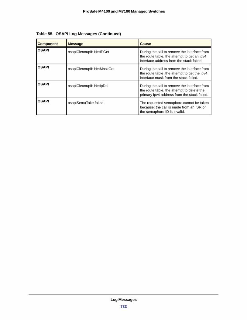
ProSafe M4100 and M7100 Managed Switches
OSAPI osapiCleanupIf: NetIPGet During the call to remove the interface from the route table, the attempt to get an ipv4 interface address from the stack failed.
OSAPI osapiCleanupIf: NetMaskGet During the call to remove the interface from the route table ,the attempt to get the ipv4 interface mask from the stack failed.
OSAPI osapiCleanupIf: NetIpDel During the call to remove the interface from the route table, the attempt to delete the primary ipv4 address from the stack failed.
OSAPI osapiSemaTake failed The requested semaphore cannot be taken because: the call is made from an ISR or the semaphore ID is invalid.
Table 55. OSAPI Log Messages (Continued)
Component Message Cause
Log Messages
733
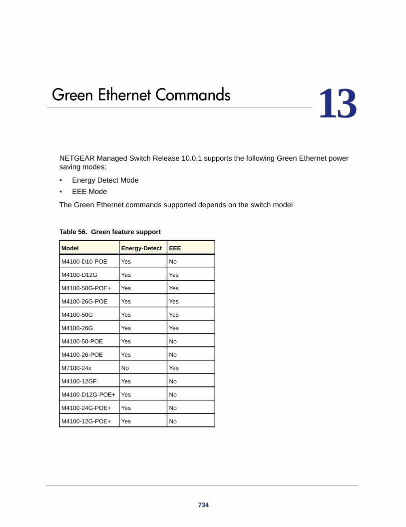
3
113. Green Ethernet CommandsNETGEAR Managed Switch Release 10.0.1 supports the following Green Ethernet power saving modes:
• Energy Detect Mode• EEE Mode
The Green Ethernet commands supported depends on the switch model
Table 56. Green feature support
Model Energy-Detect EEE
M4100-D10-POE Yes No
M4100-D12G Yes Yes
M4100-50G-POE+ Yes Yes
M4100-26G-POE Yes Yes
M4100-50G Yes Yes
M4100-26G Yes Yes
M4100-50-POE Yes No
M4100-26-POE Yes No
M7100-24x No Yes
M4100-12GF Yes No
M4100-D12G-POE+ Yes No
M4100-24G-POE+ Yes No
M4100-12G-POE+ Yes No
734
ProSafe M4100 and M7100 Managed Switches
Energy-Detect Mode
When Energy-Detect mode is enabled, if communication on a port stops, the port circuitry automatically shuts down for a short period. The port wakes up periodically to check for link activity. If activity is detected, the port circuitry remains active. This allows performing autonegotiation and saving power when there is no active link.
Note: Combination ports support both copper and fiber media. Energy Detect mode only applies to copper media. If Energy Detect mode is configured on a combination port, it will only function when a copper media is active.
Energy Efficient Ethernet (EEE)
Energy Efficient Ethernet (EEE) combines MAC with ports that support operation in a Low-Power Mode. This feature is defined by the IEEE 802.3az Energy Efficient Ethernet Task Force. Lower Power Mode enables both send and receive sides of a link to disable some port functionality to save power when the port is lightly loaded. Transition to Low-Power Mode does not change the link status. Frames in transit are not dropped or corrupted during transition to and from Low-Power Mode. This transition time is transparent to upper layer protocols and applications.
EEE operation is subject to the following conditions:
• Autonegotiation must be enabled to use any of the EEE modes. EEE mode is disabled automatically when autonegotiation is disabled.
• Enabling or Disabling EEE mode causes the port link to flap once as EEE capability needs to be advertised. This restarts autonegotiation.
• EEE must be disabled while running hardware or software cable diagnostics. • Combo (Combination) ports: Combo ports support both copper and fiber media. EEE
mode only applies to copper media. If Energy Detect mode is configured on a combination port, it will only function when a copper media is active. EEE LPI statistics are only collected if a copper media is used on the port. If the media on a port changes from copper to fiber while EEE is enabled, LPI statistics collection stops until the media changes back to copper. The show green-mode <u/s/p> and show green-mode eee-lpi-history interface <u/s/p> commands display updated LPI statistics only if the medium is copper.
Green Ethernet Commands
735
ProSafe M4100 and M7100 Managed Switches
green-mode energy-detect
Use this command enables energy-detect mode on an interface or on all the interfaces.
Format green-mode energy-detect
Mode
Default
no green-mode energy-detect
This command disables energy-detect mode on an interface or on all the interfaces.
Format no green-mode energy-detect
Mode
green-mode eee
This command enables EEE low-power idle mode on an interface or on all interfaces. It allows both send and receive sides of a link to disable some functionality for power savings when the port is lightly loaded. Transition to Low-Power Mode does not change the link status. Frames in transit are not dropped or corrupted in transition to and from Low-Power Mode.
Format green-mode eee
Mode
Default
no green-mode eee
This command disables EEE.
Format no green-mode eee
Mode
Interface ConfigInterface Range Config
Disabled
Interface ConfigInterface Range Config
Interface ConfigInterface Range Config
Disabled
Interface ConfigInterface Range Config
Green Ethernet Commands
736
ProSafe M4100 and M7100 Managed Switches
clear green-mode statistics
This command to clears the following for a specified <slot/port>, or for all ports:
• EEE LPI event count, and LPI duration• EEE LPI history table entries• Cumulative Power savings estimates
Format clear green-mode statistics {<slot/port> | all}
Mode
Example
(switch) #clear green-mode statistics 0/1Are you sure you want to clear the green mode port stats? (y/n)yGreen Mode Stats Cleared.(switch) #clear green-mode statistics allAre you sure you want to clear the green mode port stats? (y/n)yGreen Mode Stats Cleared.
show green-mode <slot/port>
This command displays green mode configuration and operational status of a port. This command can also display the per port configuration and operational status of the green-mode. The status is shown only for the modes supported on the switch.
Format show green-mode <slot/port>
Mode
Privileged Exec
Privileged Exec
Table 57. Green-Mode status terms
Term Definition
Energy-detect admin mode
Energy-detect mode is enabled or disabled.
Energy-detect operational status
Energy detect mode is currently active or inactive. The energy detect mode might be administratively enabled, but the operational status might be inactive. The reasons for the same are described below.
Reason for Energy-detect current operational status
The energy detect mode might be administratively enabled, but the operational status might be inactive. The reasons for the same are:
- Port is currently operating in the fiber mode- Link is up. - Admin Mode Disabled - Interface Not Attached
If the energy-detect operational status is active, the reason field displays No energy Detected
Green Ethernet Commands
737
ProSafe M4100 and M7100 Managed Switches
EEE
EEE Admin Mode EEE Admin Mode is enabled or disabled.
Transmit Idle Time It is the time for which condition to move to LPI state is satisfied, at the end of which MAC TX transitions to LPI state. The Range is (0 to 0xffffffff).The default value is 0.
Transmit Wake Time It is the time for which MAC / switch has to wait to go back to ACTIVE state from LPI state when it receives packet for transmission. The Range is (0 to 0xffff).The default value is 0.
Rx Low Power Idle Event Count
This field is incremented each time MAC RX enters LP IDLE state. Shows the total number of Rx LPI Events since EEE counters are last cleared
Rx Low Power Idle Duration (microsec)
This field indicates duration of Rx LPI state in 10-microsecond increments. Shows the total duration of Rx LPI since the EEE counters are last cleared.
Tx Low Power Idle Event Count
This field is incremented each time MAC TX enters LP IDLE state. Shows the total number of Tx LPI Events since EEE counters are last cleared.
Tx Low Power Idle Duration (microsec)
This field indicates duration of Tx LPI state in 10us increments. Shows the total duration of Tx LPI since the EEE counters are last cleared.
Tw_sys_tx (microsec) Integer that indicates the value of Tw_sys that the local system can support. This value is updated by the EEE DLL Transmitter state diagram. This variable maps into the aLldpXdot3LocTxTwSys attribute.
Tw_sys Echo (microsec) Integer that indicates the remote system's Transmit Tw_sys that was used by the local system to compute the Tw_sys that it wants to request from the remote system. This value maps into the aLldpXdot3LocTxTwSysEcho attribute.
Tw_sys_rx (microsec) Integer that indicates the value of Tw_sys that the local system requests from the remote system. This value is updated by the EEE Receiver L2 state diagram. This variable maps into the aLldpXdot3LocRxTwSys attribute.
Tw_sys_rx Echo (microsec)
Integer that indicates the remote systems Receive Tw_sys that was used by the local system to compute the Tw_sys that it can support. This value maps into the aLldpXdot3LocRxTwSysEcho attribute.
Fallback Tw_sys (microsec)
Integer that indicates the value of fallback Tw_sys that the local system requests from the remote system. This value is updated by the local system software.
Remote Tw_sys_tx (microsec)
Integer that indicates the value of Tw_sys that the remote system can support. This value maps from the aLldpXdot3RemTxTwSys attribute.
Remote Tw_sys Echo (microsec)
Integer that indicates the value Transmit Tw_sys echoed back by the remote system. This value maps from the aLldpXdot3RemTxTwSysEcho attribute.
Remote Tw_sys_rx (microsec)
Integer that indicates the value of Tw_sys that the remote system requests from the local system. This value maps from the aLldpXdot3RemRxTwSys attribute.
Remote Tw_sys_rx Echo (microsec)
Integer that indicates the value of Receive Tw_sys echoed back by the remote system. This value maps from the aLldpXdot3RemRxTwSysEcho attribute.
Remote Fallback Tw_sys (microsec)
Integer that indicates the value of fallback Tw_sys that the remote system is advertising. This attribute maps to the variable RemFbSystemValue as defined in 78.4.2.3.
Tx_dll_enabled Initialization status of the EEE transmit Data Link Layer management function on the local system.
Table 57. Green-Mode status terms
Term Definition
Green Ethernet Commands
738
ProSafe M4100 and M7100 Managed Switches
Note: Executing 'clear green-mode statistics' only clears the EEE Transmit, Receive LPI event count, LPI duration, and Cumulative Energy Savings Estimates of the port. Other status parameters listed in above table will remain unaffected after 'clear green-mode statistics'.
Example:
The output of 'show green-mode <s/p>' is indicated below.
(switch) #show green-mode 0/25
EEE Admin Mode................................. Enabled Transmit Idle Time......................... 0 Transmit Wake Time......................... 0 Rx Low Power Idle Event Count.............. 0 Rx Low Power Idle Duration (uSec).......... 0 Tx Low Power Idle Event Count.............. 0 Tx Low Power Idle Duration (uSec).......... 0 Tw_sys_tx (usec)........................... XX Tw_sys_tx Echo (usec)...................... XX Tw_sys_rx (usec)........................... XX Tw_sys_rx Echo (usec)...................... XX Fallback Tw_sys (usec)..................... XX Tx DLL enabled............................. Yes Tx DLL ready............................... Yes Rx DLL enabled............................. Yes Rx DLL ready............................... Yes
Tx_dll_ready Data Link Layer ready: This variable indicates that the tx system initialization is complete and is ready to update/receive LLDPDU containing EEE TLV. This variable is updated by the local system software.
Rx_dll_enabled Status of the EEE capability negotiation on the local system.
Rx_dll_ready Data Link Layer ready: This variable indicates that the rx system initialization is complete and is ready to update/receive LLDPDU containing EEE TLV. This variable is updated by the local system software.
Cumulative Energy Saving
Estimated Cumulative energy saved on this port in (Watts * hours) due to all green modes enabled
Time Since Counters Last Cleared
Time Since Counters Last Cleared (since the time of power up, or after 'clear eee counters' is executed)
Table 57. Green-Mode status terms
Term Definition
Green Ethernet Commands
739
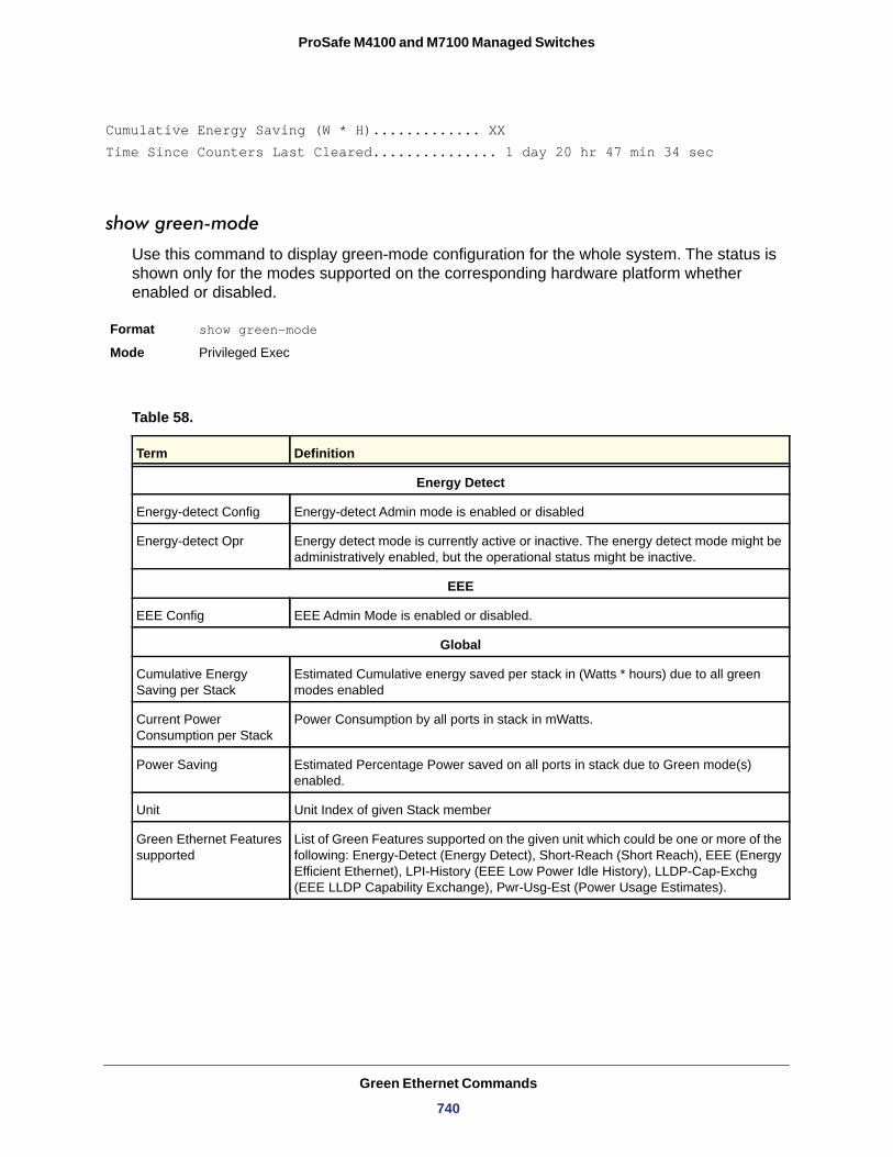
ProSafe M4100 and M7100 Managed Switches
Cumulative Energy Saving (W * H)............. XX Time Since Counters Last Cleared............... 1 day 20 hr 47 min 34 sec
show green-mode
Use this command to display green-mode configuration for the whole system. The status is shown only for the modes supported on the corresponding hardware platform whether enabled or disabled.
Format show green-mode
Mode
Table 58.
Privileged Exec
Term Definition
Energy Detect
Energy-detect Config Energy-detect Admin mode is enabled or disabled
Energy-detect Opr Energy detect mode is currently active or inactive. The energy detect mode might be administratively enabled, but the operational status might be inactive.
EEE
EEE Config EEE Admin Mode is enabled or disabled.
Global
Cumulative Energy Saving per Stack
Estimated Cumulative energy saved per stack in (Watts * hours) due to all green modes enabled
Current Power Consumption per Stack
Power Consumption by all ports in stack in mWatts.
Power Saving Estimated Percentage Power saved on all ports in stack due to Green mode(s) enabled.
Unit Unit Index of given Stack member
Green Ethernet Features supported
List of Green Features supported on the given unit which could be one or more of the following: Energy-Detect (Energy Detect), Short-Reach (Short Reach), EEE (Energy Efficient Ethernet), LPI-History (EEE Low Power Idle History), LLDP-Cap-Exchg (EEE LLDP Capability Exchange), Pwr-Usg-Est (Power Usage Estimates).
Green Ethernet Commands
740
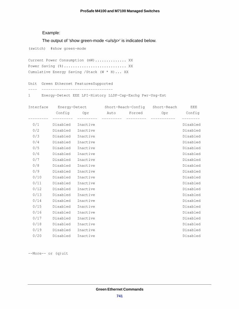
ProSafe M4100 and M7100 Managed Switches
Example:
The output of 'show green-mode <u/s/p>' is indicated below.
(switch) #show green-mode
Current Power Consumption (mW).............. XX Power Saving (%)............................ XX Cumulative Energy Saving /Stack (W * H)... XX
Unit Green Ethernet FeaturesSupported---- --------------------------------1 Energy-Detect EEE LPI-History LLDP-Cap-Exchg Pwr-Usg-Est
Interface Energy-Detect Short-Reach-Config Short-Reach EEE Config Opr Auto Forced Opr Config
--------- --------- --------- --------- --------- ----------- -------- 0/1 Disabled Inactive Disabled 0/2 Disabled Inactive Disabled 0/3 Disabled Inactive Disabled 0/4 Disabled Inactive Disabled 0/5 Disabled Inactive Disabled 0/6 Disabled Inactive Disabled 0/7 Disabled Inactive Disabled 0/8 Disabled Inactive Disabled 0/9 Disabled Inactive Disabled 0/10 Disabled Inactive Disabled 0/11 Disabled Inactive Disabled 0/12 Disabled Inactive Disabled 0/13 Disabled Inactive Disabled 0/14 Disabled Inactive Disabled 0/15 Disabled Inactive Disabled 0/16 Disabled Inactive Disabled 0/17 Disabled Inactive Disabled 0/18 Disabled Inactive Disabled 0/19 Disabled Inactive Disabled 0/20 Disabled Inactive Disabled
--More-- or (q)uit
Green Ethernet Commands
741
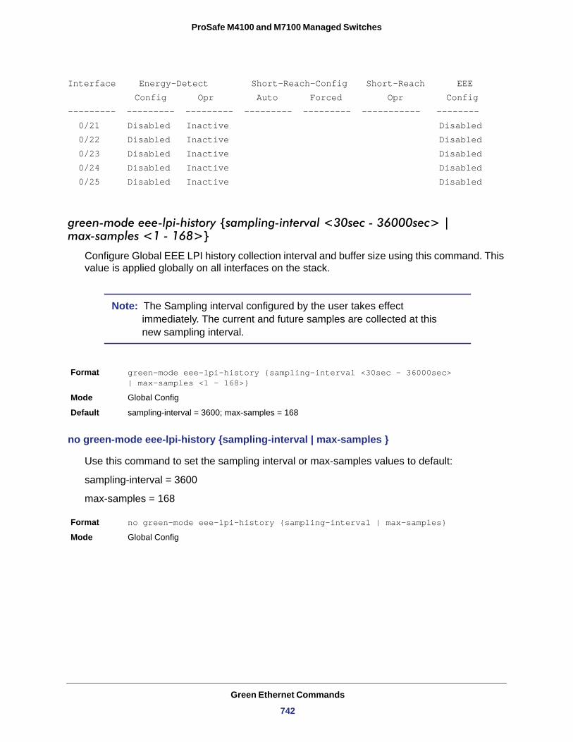
ProSafe M4100 and M7100 Managed Switches
Interface Energy-Detect Short-Reach-Config Short-Reach EEE Config Opr Auto Forced Opr Config--------- --------- --------- --------- --------- ----------- -------- 0/21 Disabled Inactive Disabled 0/22 Disabled Inactive Disabled 0/23 Disabled Inactive Disabled 0/24 Disabled Inactive Disabled 0/25 Disabled Inactive Disabled
green-mode eee-lpi-history {sampling-interval <30sec - 36000sec> | max-samples <1 - 168>}
Configure Global EEE LPI history collection interval and buffer size using this command. This value is applied globally on all interfaces on the stack.
Note: The Sampling interval configured by the user takes effect immediately. The current and future samples are collected at this new sampling interval.
Format green-mode eee-lpi-history {sampling-interval <30sec - 36000sec> | max-samples <1 - 168>}
Mode
Default
no green-mode eee-lpi-history {sampling-interval | max-samples }
Use this command to set the sampling interval or max-samples values to default:
sampling-interval = 3600
max-samples = 168
Format no green-mode eee-lpi-history {sampling-interval | max-samples}
Mode
Global Config
sampling-interval = 3600; max-samples = 168
Global Config
Green Ethernet Commands
742
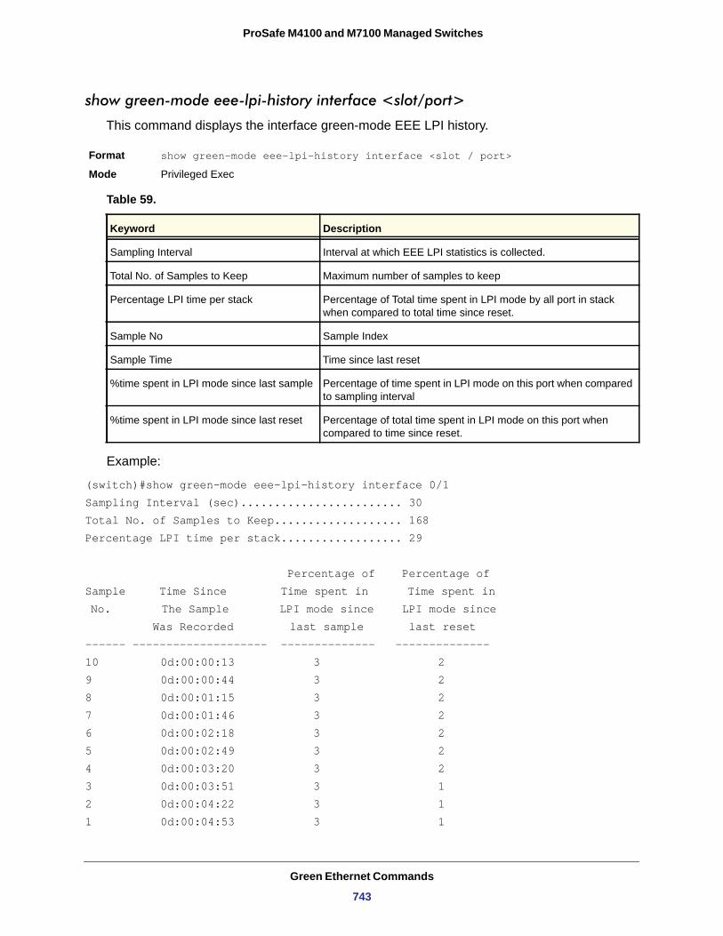
ProSafe M4100 and M7100 Managed Switches
show green-mode eee-lpi-history interface <slot/port>
This command displays the interface green-mode EEE LPI history.
Format show green-mode eee-lpi-history interface <slot / port>
Mode
Table 59.
Example:
(switch)#show green-mode eee-lpi-history interface 0/1Sampling Interval (sec)........................ 30Total No. of Samples to Keep................... 168Percentage LPI time per stack.................. 29
Percentage of Percentage of Sample Time Since Time spent in Time spent in No. The Sample LPI mode since LPI mode since Was Recorded last sample last reset------ -------------------- -------------- --------------10 0d:00:00:13 3 29 0d:00:00:44 3 28 0d:00:01:15 3 27 0d:00:01:46 3 26 0d:00:02:18 3 25 0d:00:02:49 3 24 0d:00:03:20 3 23 0d:00:03:51 3 12 0d:00:04:22 3 11 0d:00:04:53 3 1
Privileged Exec
Keyword Description
Sampling Interval Interval at which EEE LPI statistics is collected.
Total No. of Samples to Keep Maximum number of samples to keep
Percentage LPI time per stack Percentage of Total time spent in LPI mode by all port in stack when compared to total time since reset.
Sample No Sample Index
Sample Time Time since last reset
%time spent in LPI mode since last sample Percentage of time spent in LPI mode on this port when compared to sampling interval
%time spent in LPI mode since last reset Percentage of total time spent in LPI mode on this port when compared to time since reset.
Green Ethernet Commands
743
4
114. Command Listip vrrp (Global Config) . . . . . . . . . . . . . . . . . . . . . . . . . . . . . . . . . . . . . . . . . . . . . . . . . . . . . . . . 249{deny | permit} (IP ACL) . . . . . . . . . . . . . . . . . . . . . . . . . . . . . . . . . . . . . . . . . . . . . . . . . . . . . . 480{deny | permit} (IPv6) . . . . . . . . . . . . . . . . . . . . . . . . . . . . . . . . . . . . . . . . . . . . . . . . . . . . . . . . 485{deny | permit} (MAC ACL) . . . . . . . . . . . . . . . . . . . . . . . . . . . . . . . . . . . . . . . . . . . . . . . . . . . . 4741583compatibility . . . . . . . . . . . . . . . . . . . . . . . . . . . . . . . . . . . . . . . . . . . . . . . . . . . . . . . . . . . 264aaa accounting . . . . . . . . . . . . . . . . . . . . . . . . . . . . . . . . . . . . . . . . . . . . . . . . . . . . . . . . . . . . . 662aaa authentication dot1x . . . . . . . . . . . . . . . . . . . . . . . . . . . . . . . . . . . . . . . . . . . . . . . . . . . . . . 661aaa authentication enable . . . . . . . . . . . . . . . . . . . . . . . . . . . . . . . . . . . . . . . . . . . . . . . . . . . . . 660aaa authentication login . . . . . . . . . . . . . . . . . . . . . . . . . . . . . . . . . . . . . . . . . . . . . . . . . . . . . . 659aaa authorization . . . . . . . . . . . . . . . . . . . . . . . . . . . . . . . . . . . . . . . . . . . . . . . . . . . . . . . . . . . 665aaa ias-user username . . . . . . . . . . . . . . . . . . . . . . . . . . . . . . . . . . . . . . . . . . . . . . . . . . . . . . . 668aaa session-id . . . . . . . . . . . . . . . . . . . . . . . . . . . . . . . . . . . . . . . . . . . . . . . . . . . . . . . . . . . . . . 669absolute . . . . . . . . . . . . . . . . . . . . . . . . . . . . . . . . . . . . . . . . . . . . . . . . . . . . . . . . . . . . . . . . . . 488access-list . . . . . . . . . . . . . . . . . . . . . . . . . . . . . . . . . . . . . . . . . . . . . . . . . . . . . . . . . . . . . . . . . 478accounting (Console/Telnet/SSH) . . . . . . . . . . . . . . . . . . . . . . . . . . . . . . . . . . . . . . . . . . . . . . . 663acl-trapflags . . . . . . . . . . . . . . . . . . . . . . . . . . . . . . . . . . . . . . . . . . . . . . . . . . . . . . . . . . . . . . . 482addport . . . . . . . . . . . . . . . . . . . . . . . . . . . . . . . . . . . . . . . . . . . . . . . . . . . . . . . . . . . . . . . . . . . 106area default-cost (OSPF) . . . . . . . . . . . . . . . . . . . . . . . . . . . . . . . . . . . . . . . . . . . . . . . . . . . . . 265area default-cost (OSPFv3) . . . . . . . . . . . . . . . . . . . . . . . . . . . . . . . . . . . . . . . . . . . . . . . . . . . 384area nssa (OSPF) . . . . . . . . . . . . . . . . . . . . . . . . . . . . . . . . . . . . . . . . . . . . . . . . . . . . . . . . . . . 265area nssa (OSPFv3) . . . . . . . . . . . . . . . . . . . . . . . . . . . . . . . . . . . . . . . . . . . . . . . . . . . . . . . . . 384area nssa default-info-originate (OSPF) . . . . . . . . . . . . . . . . . . . . . . . . . . . . . . . . . . . . . . . . . . 265area nssa default-info-originate (OSPFv3) . . . . . . . . . . . . . . . . . . . . . . . . . . . . . . . . . . . . . . . . 385area nssa no-redistribute (OSPF) . . . . . . . . . . . . . . . . . . . . . . . . . . . . . . . . . . . . . . . . . . . . . . . 266area nssa no-redistribute (OSPFv3) . . . . . . . . . . . . . . . . . . . . . . . . . . . . . . . . . . . . . . . . . . . . . 385area nssa no-summary (OSPF) . . . . . . . . . . . . . . . . . . . . . . . . . . . . . . . . . . . . . . . . . . . . . . . . 266area nssa no-summary (OSPFv3) . . . . . . . . . . . . . . . . . . . . . . . . . . . . . . . . . . . . . . . . . . . . . . 386area nssa translator-role (OSPF) . . . . . . . . . . . . . . . . . . . . . . . . . . . . . . . . . . . . . . . . . . . . . . . 266area nssa translator-role (OSPFv3) . . . . . . . . . . . . . . . . . . . . . . . . . . . . . . . . . . . . . . . . . . . . . 386area nssa translator-stab-intv (OSPF) . . . . . . . . . . . . . . . . . . . . . . . . . . . . . . . . . . . . . . . . . . . 267area nssa translator-stab-intv (OSPFv3) . . . . . . . . . . . . . . . . . . . . . . . . . . . . . . . . . . . . . . . . . 386area range (OSPF) . . . . . . . . . . . . . . . . . . . . . . . . . . . . . . . . . . . . . . . . . . . . . . . . . . . . . . . . . . 267area range (OSPFv3) . . . . . . . . . . . . . . . . . . . . . . . . . . . . . . . . . . . . . . . . . . . . . . . . . . . . . . . . 387area stub (OSPF) . . . . . . . . . . . . . . . . . . . . . . . . . . . . . . . . . . . . . . . . . . . . . . . . . . . . . . . . . . . 268area stub (OSPFv3) . . . . . . . . . . . . . . . . . . . . . . . . . . . . . . . . . . . . . . . . . . . . . . . . . . . . . . . . . 387area stub no-summary (OSPF) . . . . . . . . . . . . . . . . . . . . . . . . . . . . . . . . . . . . . . . . . . . . . . . . . 269area stub no-summary (OSPFv3) . . . . . . . . . . . . . . . . . . . . . . . . . . . . . . . . . . . . . . . . . . . . . . . 388area virtual-link (OSPF) . . . . . . . . . . . . . . . . . . . . . . . . . . . . . . . . . . . . . . . . . . . . . . . . . . . . . . 269area virtual-link (OSPFv3) . . . . . . . . . . . . . . . . . . . . . . . . . . . . . . . . . . . . . . . . . . . . . . . . . . . . 388
744
ProSafe M4100 and M7100 Managed Switches
area virtual-link authentication . . . . . . . . . . . . . . . . . . . . . . . . . . . . . . . . . . . . . . . . . . . . . . . . . 269area virtual-link dead-interval (OSPF) . . . . . . . . . . . . . . . . . . . . . . . . . . . . . . . . . . . . . . . . . . . 270area virtual-link dead-interval (OSPFv3) . . . . . . . . . . . . . . . . . . . . . . . . . . . . . . . . . . . . . . . . . 388area virtual-link hello-interval (OSPF) . . . . . . . . . . . . . . . . . . . . . . . . . . . . . . . . . . . . . . . . . . . . 271area virtual-link hello-interval (OSPFv3) . . . . . . . . . . . . . . . . . . . . . . . . . . . . . . . . . . . . . . . . . . 389area virtual-link retransmit-interval (OSPF) . . . . . . . . . . . . . . . . . . . . . . . . . . . . . . . . . . . . . . . 271area virtual-link retransmit-interval (OSPFv3) . . . . . . . . . . . . . . . . . . . . . . . . . . . . . . . . . . . . . 389area virtual-link transmit-delay (OSPF) . . . . . . . . . . . . . . . . . . . . . . . . . . . . . . . . . . . . . . . . . . 272area virtual-link transmit-delay (OSPFv3) . . . . . . . . . . . . . . . . . . . . . . . . . . . . . . . . . . . . . . . . . 390arp . . . . . . . . . . . . . . . . . . . . . . . . . . . . . . . . . . . . . . . . . . . . . . . . . . . . . . . . . . . . . . . . . . . . . . 222arp access-list . . . . . . . . . . . . . . . . . . . . . . . . . . . . . . . . . . . . . . . . . . . . . . . . . . . . . . . . . . . . . . 144arp cachesize . . . . . . . . . . . . . . . . . . . . . . . . . . . . . . . . . . . . . . . . . . . . . . . . . . . . . . . . . . . . . . 223arp dynamicrenew . . . . . . . . . . . . . . . . . . . . . . . . . . . . . . . . . . . . . . . . . . . . . . . . . . . . . . . . . . 223arp purge . . . . . . . . . . . . . . . . . . . . . . . . . . . . . . . . . . . . . . . . . . . . . . . . . . . . . . . . . . . . . . . . . 224arp resptime . . . . . . . . . . . . . . . . . . . . . . . . . . . . . . . . . . . . . . . . . . . . . . . . . . . . . . . . . . . . . . . 224arp retries . . . . . . . . . . . . . . . . . . . . . . . . . . . . . . . . . . . . . . . . . . . . . . . . . . . . . . . . . . . . . . . . . 224arp timeout . . . . . . . . . . . . . . . . . . . . . . . . . . . . . . . . . . . . . . . . . . . . . . . . . . . . . . . . . . . . . . . . 225assign-queue . . . . . . . . . . . . . . . . . . . . . . . . . . . . . . . . . . . . . . . . . . . . . . . . . . . . . . . . . . . . . . 461authorization network radius . . . . . . . . . . . . . . . . . . . . . . . . . . . . . . . . . . . . . . . . . . . . . . . . . . . 681authorization(console/telnet/ssh) . . . . . . . . . . . . . . . . . . . . . . . . . . . . . . . . . . . . . . . . . . . . . . . 666auto-cost (OSPF) . . . . . . . . . . . . . . . . . . . . . . . . . . . . . . . . . . . . . . . . . . . . . . . . . . . . . . . . . . . 272auto-cost (OSPFv3) . . . . . . . . . . . . . . . . . . . . . . . . . . . . . . . . . . . . . . . . . . . . . . . . . . . . . . . . . 390auto-negotiate . . . . . . . . . . . . . . . . . . . . . . . . . . . . . . . . . . . . . . . . . . . . . . . . . . . . . . . . . . . . . . . 21auto-negotiate all . . . . . . . . . . . . . . . . . . . . . . . . . . . . . . . . . . . . . . . . . . . . . . . . . . . . . . . . . . . . 22auto-summary . . . . . . . . . . . . . . . . . . . . . . . . . . . . . . . . . . . . . . . . . . . . . . . . . . . . . . . . . . . . . . 312auto-voip {protocol-based | oui-based} . . . . . . . . . . . . . . . . . . . . . . . . . . . . . . . . . . . . . . . . . . . 491auto-voip oui . . . . . . . . . . . . . . . . . . . . . . . . . . . . . . . . . . . . . . . . . . . . . . . . . . . . . . . . . . . . . . . 491auto-voip oui-based priority . . . . . . . . . . . . . . . . . . . . . . . . . . . . . . . . . . . . . . . . . . . . . . . . . . . 492auto-voip protocol-based {remark | traffic-class} . . . . . . . . . . . . . . . . . . . . . . . . . . . . . . . . . . . 492auto-voip vlan . . . . . . . . . . . . . . . . . . . . . . . . . . . . . . . . . . . . . . . . . . . . . . . . . . . . . . . . . . . . . . 492bandwidth . . . . . . . . . . . . . . . . . . . . . . . . . . . . . . . . . . . . . . . . . . . . . . . . . . . . . . . . . . . . . . . . . 273boot autoinstall start . . . . . . . . . . . . . . . . . . . . . . . . . . . . . . . . . . . . . . . . . . . . . . . . . . . . . . . . . 514boot autoinstall stop . . . . . . . . . . . . . . . . . . . . . . . . . . . . . . . . . . . . . . . . . . . . . . . . . . . . . . . . . 514boot host auto-save . . . . . . . . . . . . . . . . . . . . . . . . . . . . . . . . . . . . . . . . . . . . . . . . . . . . . . . . . 514boot host dhcp . . . . . . . . . . . . . . . . . . . . . . . . . . . . . . . . . . . . . . . . . . . . . . . . . . . . . . . . . . . . . 515boot host retry-count . . . . . . . . . . . . . . . . . . . . . . . . . . . . . . . . . . . . . . . . . . . . . . . . . . . . . . . . . 514boot system . . . . . . . . . . . . . . . . . . . . . . . . . . . . . . . . . . . . . . . . . . . . . . . . . . . . . . . . . . . . . . . 516bootfile . . . . . . . . . . . . . . . . . . . . . . . . . . . . . . . . . . . . . . . . . . . . . . . . . . . . . . . . . . . . . . . . . . . 567bootpdhcprelay cidoptmode . . . . . . . . . . . . . . . . . . . . . . . . . . . . . . . . . . . . . . . . . . . . . . . . . . . 257bootpdhcprelay maxhopcount . . . . . . . . . . . . . . . . . . . . . . . . . . . . . . . . . . . . . . . . . . . . . . . . . 258bootpdhcprelay minwaittime . . . . . . . . . . . . . . . . . . . . . . . . . . . . . . . . . . . . . . . . . . . . . . . . . . . 258bridge aging-time . . . . . . . . . . . . . . . . . . . . . . . . . . . . . . . . . . . . . . . . . . . . . . . . . . . . . . . . . . . 203cablestatus . . . . . . . . . . . . . . . . . . . . . . . . . . . . . . . . . . . . . . . . . . . . . . . . . . . . . . . . . . . . . . . . 604capability opaque . . . . . . . . . . . . . . . . . . . . . . . . . . . . . . . . . . . . . . . . . . . . . . . . . . . . . . . . . . . 273capture {file|remote|line} . . . . . . . . . . . . . . . . . . . . . . . . . . . . . . . . . . . . . . . . . . . . . . . . . . . . . . 581capture {start|stop} . . . . . . . . . . . . . . . . . . . . . . . . . . . . . . . . . . . . . . . . . . . . . . . . . . . . . . . . . . 580capture file size . . . . . . . . . . . . . . . . . . . . . . . . . . . . . . . . . . . . . . . . . . . . . . . . . . . . . . . . . . . . . 582capture line wrap . . . . . . . . . . . . . . . . . . . . . . . . . . . . . . . . . . . . . . . . . . . . . . . . . . . . . . . . . . . 582capture remote port . . . . . . . . . . . . . . . . . . . . . . . . . . . . . . . . . . . . . . . . . . . . . . . . . . . . . . . . . 582class . . . . . . . . . . . . . . . . . . . . . . . . . . . . . . . . . . . . . . . . . . . . . . . . . . . . . . . . . . . . . . . . . . . . . 463class-map . . . . . . . . . . . . . . . . . . . . . . . . . . . . . . . . . . . . . . . . . . . . . . . . . . . . . . . . . . . . . . . . . 453class-map rename . . . . . . . . . . . . . . . . . . . . . . . . . . . . . . . . . . . . . . . . . . . . . . . . . . . . . . . . . . 454
Command List
745
ProSafe M4100 and M7100 Managed Switches
classofservice dot1p-mapping . . . . . . . . . . . . . . . . . . . . . . . . . . . . . . . . . . . . . . . . . . . . . . . . . 444classofservice ip-dscp-mapping . . . . . . . . . . . . . . . . . . . . . . . . . . . . . . . . . . . . . . . . . . . . . . . . 444classofservice trust . . . . . . . . . . . . . . . . . . . . . . . . . . . . . . . . . . . . . . . . . . . . . . . . . . . . . . . . . . 445clear aaa ias-users . . . . . . . . . . . . . . . . . . . . . . . . . . . . . . . . . . . . . . . . . . . . . . . . . . . . . . . . . . 670clear arp-cache . . . . . . . . . . . . . . . . . . . . . . . . . . . . . . . . . . . . . . . . . . . . . . . . . . . . . . . . . . . . . 225clear arp-switch . . . . . . . . . . . . . . . . . . . . . . . . . . . . . . . . . . . . . . . . . . . . . . . . . . . . . . . . . . . . 225clear config . . . . . . . . . . . . . . . . . . . . . . . . . . . . . . . . . . . . . . . . . . . . . . . . . . . . . . . . . . . . . . . . 548clear counters . . . . . . . . . . . . . . . . . . . . . . . . . . . . . . . . . . . . . . . . . . . . . . . . . . . . . . . . . . . . . . 549clear dot1x authentication-history . . . . . . . . . . . . . . . . . . . . . . . . . . . . . . . . . . . . . . . . . . . . . . . . 84clear dot1x statistics . . . . . . . . . . . . . . . . . . . . . . . . . . . . . . . . . . . . . . . . . . . . . . . . . . . . . . . . . . 78clear eventlog . . . . . . . . . . . . . . . . . . . . . . . . . . . . . . . . . . . . . . . . . . . . . . . . . . . . . . . . . . . . . . 548clear green-mode statistics . . . . . . . . . . . . . . . . . . . . . . . . . . . . . . . . . . . . . . . . . . . . . . . . . . . . 737clear host . . . . . . . . . . . . . . . . . . . . . . . . . . . . . . . . . . . . . . . . . . . . . . . . . . . . . . . . . . . . . . . . . 579clear igmpsnooping . . . . . . . . . . . . . . . . . . . . . . . . . . . . . . . . . . . . . . . . . . . . . . . . . . . . . . . . . 549clear ip address-conflict-detect . . . . . . . . . . . . . . . . . . . . . . . . . . . . . . . . . . . . . . . . . . . . . . . . . 611clear ip arp inspection statistics . . . . . . . . . . . . . . . . . . . . . . . . . . . . . . . . . . . . . . . . . . . . . . . . 146clear ip dhcp binding . . . . . . . . . . . . . . . . . . . . . . . . . . . . . . . . . . . . . . . . . . . . . . . . . . . . . . . . 572clear ip dhcp conflict . . . . . . . . . . . . . . . . . . . . . . . . . . . . . . . . . . . . . . . . . . . . . . . . . . . . . . . . . 572clear ip dhcp server statistics . . . . . . . . . . . . . . . . . . . . . . . . . . . . . . . . . . . . . . . . . . . . . . . . . . 572clear ip dhcp snooping binding . . . . . . . . . . . . . . . . . . . . . . . . . . . . . . . . . . . . . . . . . . . . . . . . . 139clear ip dhcp snooping statistics . . . . . . . . . . . . . . . . . . . . . . . . . . . . . . . . . . . . . . . . . . . . . . . . 139clear ip helper statistics . . . . . . . . . . . . . . . . . . . . . . . . . . . . . . . . . . . . . . . . . . . . . . . . . . . . . . 259clear ip ospf . . . . . . . . . . . . . . . . . . . . . . . . . . . . . . . . . . . . . . . . . . . . . . . . . . . . . . . . . . . . . . . 273clear ip ospf configuration . . . . . . . . . . . . . . . . . . . . . . . . . . . . . . . . . . . . . . . . . . . . . . . . . . . . 274clear ip ospf counters . . . . . . . . . . . . . . . . . . . . . . . . . . . . . . . . . . . . . . . . . . . . . . . . . . . . . . . . 274clear ip ospf neighbor . . . . . . . . . . . . . . . . . . . . . . . . . . . . . . . . . . . . . . . . . . . . . . . . . . . . . . . . 274clear ip ospf neighbor interface . . . . . . . . . . . . . . . . . . . . . . . . . . . . . . . . . . . . . . . . . . . . . . . . 274clear ip ospf redistribution . . . . . . . . . . . . . . . . . . . . . . . . . . . . . . . . . . . . . . . . . . . . . . . . . . . . . 274clear ip ospf stub-router . . . . . . . . . . . . . . . . . . . . . . . . . . . . . . . . . . . . . . . . . . . . . . . . . . . . . . 274clear ip route all . . . . . . . . . . . . . . . . . . . . . . . . . . . . . . . . . . . . . . . . . . . . . . . . . . . . . . . . . . . . 234clear ip route counters . . . . . . . . . . . . . . . . . . . . . . . . . . . . . . . . . . . . . . . . . . . . . . . . . . . . . . . 234clear ipv6 dhcp . . . . . . . . . . . . . . . . . . . . . . . . . . . . . . . . . . . . . . . . . . . . . . . . . . . . . . . . . . . . . 418clear ipv6 neighbors . . . . . . . . . . . . . . . . . . . . . . . . . . . . . . . . . . . . . . . . . . . . . . . . . . . . . . . . . 370clear ipv6 ospf . . . . . . . . . . . . . . . . . . . . . . . . . . . . . . . . . . . . . . . . . . . . . . . . . . . . . . . . . . . . . 391clear ipv6 ospf configuration . . . . . . . . . . . . . . . . . . . . . . . . . . . . . . . . . . . . . . . . . . . . . . . . . . . 391clear ipv6 ospf counters . . . . . . . . . . . . . . . . . . . . . . . . . . . . . . . . . . . . . . . . . . . . . . . . . . . . . . 391clear ipv6 ospf neighbor . . . . . . . . . . . . . . . . . . . . . . . . . . . . . . . . . . . . . . . . . . . . . . . . . . . . . . 391clear ipv6 ospf neighbor interface . . . . . . . . . . . . . . . . . . . . . . . . . . . . . . . . . . . . . . . . . . . . . . . 392clear ipv6 ospf redistribution . . . . . . . . . . . . . . . . . . . . . . . . . . . . . . . . . . . . . . . . . . . . . . . . . . . 392clear ipv6 route counters . . . . . . . . . . . . . . . . . . . . . . . . . . . . . . . . . . . . . . . . . . . . . . . . . . . . . 379clear ipv6 statistics . . . . . . . . . . . . . . . . . . . . . . . . . . . . . . . . . . . . . . . . . . . . . . . . . . . . . . . . . . 380clear isdp counters . . . . . . . . . . . . . . . . . . . . . . . . . . . . . . . . . . . . . . . . . . . . . . . . . . . . . . . . . . 207clear isdp table . . . . . . . . . . . . . . . . . . . . . . . . . . . . . . . . . . . . . . . . . . . . . . . . . . . . . . . . . . . . . 207clear lldp remote-data . . . . . . . . . . . . . . . . . . . . . . . . . . . . . . . . . . . . . . . . . . . . . . . . . . . . . . . . 178clear lldp statistics . . . . . . . . . . . . . . . . . . . . . . . . . . . . . . . . . . . . . . . . . . . . . . . . . . . . . . . . . . 178clear logging buffered . . . . . . . . . . . . . . . . . . . . . . . . . . . . . . . . . . . . . . . . . . . . . . . . . . . . . . . . 548clear logging email statistics . . . . . . . . . . . . . . . . . . . . . . . . . . . . . . . . . . . . . . . . . . . . . . . . . . . 544clear mac-addr-table . . . . . . . . . . . . . . . . . . . . . . . . . . . . . . . . . . . . . . . . . . . . . . . . . . . . . . . . . 548clear network ipv6 dhcp statistics . . . . . . . . . . . . . . . . . . . . . . . . . . . . . . . . . . . . . . . . . . . . . . . 707clear pass . . . . . . . . . . . . . . . . . . . . . . . . . . . . . . . . . . . . . . . . . . . . . . . . . . . . . . . . . . . . . . . . . 549clear port-channel . . . . . . . . . . . . . . . . . . . . . . . . . . . . . . . . . . . . . . . . . . . . . . . . . . . . . . . . . . . 549clear radius statistics . . . . . . . . . . . . . . . . . . . . . . . . . . . . . . . . . . . . . . . . . . . . . . . . . . . . . . . . . 78
Command List
746
ProSafe M4100 and M7100 Managed Switches
clear traplog . . . . . . . . . . . . . . . . . . . . . . . . . . . . . . . . . . . . . . . . . . . . . . . . . . . . . . . . . . . . . . . 549clear vlan . . . . . . . . . . . . . . . . . . . . . . . . . . . . . . . . . . . . . . . . . . . . . . . . . . . . . . . . . . . . . . . . . 549client-identifier . . . . . . . . . . . . . . . . . . . . . . . . . . . . . . . . . . . . . . . . . . . . . . . . . . . . . . . . . . . . . 564client-name . . . . . . . . . . . . . . . . . . . . . . . . . . . . . . . . . . . . . . . . . . . . . . . . . . . . . . . . . . . . . . . . 565clock set . . . . . . . . . . . . . . . . . . . . . . . . . . . . . . . . . . . . . . . . . . . . . . . . . . . . . . . . . . . . . . . . . . 560clock summer-time date . . . . . . . . . . . . . . . . . . . . . . . . . . . . . . . . . . . . . . . . . . . . . . . . . . . . . . 560clock summer-time recurring . . . . . . . . . . . . . . . . . . . . . . . . . . . . . . . . . . . . . . . . . . . . . . . . . . 560clock timezone . . . . . . . . . . . . . . . . . . . . . . . . . . . . . . . . . . . . . . . . . . . . . . . . . . . . . . . . . . . . . 559configuration . . . . . . . . . . . . . . . . . . . . . . . . . . . . . . . . . . . . . . . . . . . . . . . . . . . . . . . . . . . . . . . 629conform-color . . . . . . . . . . . . . . . . . . . . . . . . . . . . . . . . . . . . . . . . . . . . . . . . . . . . . . . . . . . . . . 462copy . . . . . . . . . . . . . . . . . . . . . . . . . . . . . . . . . . . . . . . . . . . . . . . . . . . . . . . . . . . . . . . . . . . . . 553copy (pre-login banner) . . . . . . . . . . . . . . . . . . . . . . . . . . . . . . . . . . . . . . . . . . . . . . . . . . . . . . 700cos-queue min-bandwidth . . . . . . . . . . . . . . . . . . . . . . . . . . . . . . . . . . . . . . . . . . . . . . . . . . . . 445cos-queue random-detect . . . . . . . . . . . . . . . . . . . . . . . . . . . . . . . . . . . . . . . . . . . . . . . . . . . . . 446cos-queue strict . . . . . . . . . . . . . . . . . . . . . . . . . . . . . . . . . . . . . . . . . . . . . . . . . . . . . . . . . . . . 446crypto certificate generate . . . . . . . . . . . . . . . . . . . . . . . . . . . . . . . . . . . . . . . . . . . . . . . . . . . . 639crypto key generate dsa . . . . . . . . . . . . . . . . . . . . . . . . . . . . . . . . . . . . . . . . . . . . . . . . . . . . . . 640crypto key generate rsa . . . . . . . . . . . . . . . . . . . . . . . . . . . . . . . . . . . . . . . . . . . . . . . . . . . . . . 639Dampening . . . . . . . . . . . . . . . . . . . . . . . . . . . . . . . . . . . . . . . . . . . . . . . . . . . . . . . . . . . . . . . . 309datacenter-bridging . . . . . . . . . . . . . . . . . . . . . . . . . . . . . . . . . . . . . . . . . . . . . . . . . . . . . . . . . . 211debug aaa accounting . . . . . . . . . . . . . . . . . . . . . . . . . . . . . . . . . . . . . . . . . . . . . . . . . . . . . . . 603debug aaa authorization . . . . . . . . . . . . . . . . . . . . . . . . . . . . . . . . . . . . . . . . . . . . . . . . . . . . . . 603debug arp . . . . . . . . . . . . . . . . . . . . . . . . . . . . . . . . . . . . . . . . . . . . . . . . . . . . . . . . . . . . . . . . . 583debug auto-voip . . . . . . . . . . . . . . . . . . . . . . . . . . . . . . . . . . . . . . . . . . . . . . . . . . . . . . . . . . . . 584debug clear . . . . . . . . . . . . . . . . . . . . . . . . . . . . . . . . . . . . . . . . . . . . . . . . . . . . . . . . . . . . . . . . 584debug console . . . . . . . . . . . . . . . . . . . . . . . . . . . . . . . . . . . . . . . . . . . . . . . . . . . . . . . . . . . . . 584debug crashlog . . . . . . . . . . . . . . . . . . . . . . . . . . . . . . . . . . . . . . . . . . . . . . . . . . . . . . . . . . . . . 585debug dhcp packet . . . . . . . . . . . . . . . . . . . . . . . . . . . . . . . . . . . . . . . . . . . . . . . . . . . . . . . . . . 586debug dot1x packet . . . . . . . . . . . . . . . . . . . . . . . . . . . . . . . . . . . . . . . . . . . . . . . . . . . . . . . . . 586debug igmpsnooping packet . . . . . . . . . . . . . . . . . . . . . . . . . . . . . . . . . . . . . . . . . . . . . . . . . . . 586debug igmpsnooping packet receive . . . . . . . . . . . . . . . . . . . . . . . . . . . . . . . . . . . . . . . . . . . . 588debug igmpsnooping packet transmit . . . . . . . . . . . . . . . . . . . . . . . . . . . . . . . . . . . . . . . . . . . . 587debug ip acl . . . . . . . . . . . . . . . . . . . . . . . . . . . . . . . . . . . . . . . . . . . . . . . . . . . . . . . . . . . . . . . 589debug ip dvmrp packet . . . . . . . . . . . . . . . . . . . . . . . . . . . . . . . . . . . . . . . . . . . . . . . . . . . . . . . 589debug ip igmp packet . . . . . . . . . . . . . . . . . . . . . . . . . . . . . . . . . . . . . . . . . . . . . . . . . . . . . . . . 590debug ip mcache packet . . . . . . . . . . . . . . . . . . . . . . . . . . . . . . . . . . . . . . . . . . . . . . . . . . . . . . 590debug ip pimdm packet . . . . . . . . . . . . . . . . . . . . . . . . . . . . . . . . . . . . . . . . . . . . . . . . . . . . . . 591debug ip pimsm packet . . . . . . . . . . . . . . . . . . . . . . . . . . . . . . . . . . . . . . . . . . . . . . . . . . . . . . . 591debug ip vrrp . . . . . . . . . . . . . . . . . . . . . . . . . . . . . . . . . . . . . . . . . . . . . . . . . . . . . . . . . . . . . . . 591debug ipv6 dhcp . . . . . . . . . . . . . . . . . . . . . . . . . . . . . . . . . . . . . . . . . . . . . . . . . . . . . . . . . . . . 592debug ipv6 mcache packet . . . . . . . . . . . . . . . . . . . . . . . . . . . . . . . . . . . . . . . . . . . . . . . . . . . . 592debug ipv6 mld packet . . . . . . . . . . . . . . . . . . . . . . . . . . . . . . . . . . . . . . . . . . . . . . . . . . . . . . . 593debug ipv6 ospfv3 packet . . . . . . . . . . . . . . . . . . . . . . . . . . . . . . . . . . . . . . . . . . . . . . . . . . . . . 597debug ipv6 pimdm packet . . . . . . . . . . . . . . . . . . . . . . . . . . . . . . . . . . . . . . . . . . . . . . . . . . . . . 593debug ipv6 pimsm packet . . . . . . . . . . . . . . . . . . . . . . . . . . . . . . . . . . . . . . . . . . . . . . . . . . . . . 593debug isdp packet . . . . . . . . . . . . . . . . . . . . . . . . . . . . . . . . . . . . . . . . . . . . . . . . . . . . . . . . . . 210debug lacp packet . . . . . . . . . . . . . . . . . . . . . . . . . . . . . . . . . . . . . . . . . . . . . . . . . . . . . . . . . . 594debug mldsnooping packet . . . . . . . . . . . . . . . . . . . . . . . . . . . . . . . . . . . . . . . . . . . . . . . . . . . . 594debug ospf packet . . . . . . . . . . . . . . . . . . . . . . . . . . . . . . . . . . . . . . . . . . . . . . . . . . . . . . . . . . 595debug ping packet . . . . . . . . . . . . . . . . . . . . . . . . . . . . . . . . . . . . . . . . . . . . . . . . . . . . . . . . . . 597debug rip packet . . . . . . . . . . . . . . . . . . . . . . . . . . . . . . . . . . . . . . . . . . . . . . . . . . . . . . . . . . . . 598debug sflow packet . . . . . . . . . . . . . . . . . . . . . . . . . . . . . . . . . . . . . . . . . . . . . . . . . . . . . . . . . . 599
Command List
747
ProSafe M4100 and M7100 Managed Switches
debug spanning-tree bpdu . . . . . . . . . . . . . . . . . . . . . . . . . . . . . . . . . . . . . . . . . . . . . . . . . . . . 600debug spanning-tree bpdu receive . . . . . . . . . . . . . . . . . . . . . . . . . . . . . . . . . . . . . . . . . . . . . . 600debug spanning-tree bpdu transmit . . . . . . . . . . . . . . . . . . . . . . . . . . . . . . . . . . . . . . . . . . . . . 601debug tacacs packet . . . . . . . . . . . . . . . . . . . . . . . . . . . . . . . . . . . . . . . . . . . . . . . . . . . . . . . . 694debug udld packet . . . . . . . . . . . . . . . . . . . . . . . . . . . . . . . . . . . . . . . . . . . . . . . . . . . . . . . . . . 602debug udld packet receive . . . . . . . . . . . . . . . . . . . . . . . . . . . . . . . . . . . . . . . . . . . . . . . . . . . . 602debug udld packet transmit . . . . . . . . . . . . . . . . . . . . . . . . . . . . . . . . . . . . . . . . . . . . . . . . . . . 602default-information originate (OSPF) . . . . . . . . . . . . . . . . . . . . . . . . . . . . . . . . . . . . . . . . . . . . 275default-information originate (OSPFv3) . . . . . . . . . . . . . . . . . . . . . . . . . . . . . . . . . . . . . . . . . . 392default-information originate (RIP) . . . . . . . . . . . . . . . . . . . . . . . . . . . . . . . . . . . . . . . . . . . . . . 312default-metric (OSPF) . . . . . . . . . . . . . . . . . . . . . . . . . . . . . . . . . . . . . . . . . . . . . . . . . . . . . . . . 275default-metric (OSPFv3) . . . . . . . . . . . . . . . . . . . . . . . . . . . . . . . . . . . . . . . . . . . . . . . . . . . . . . 392default-metric (RIP) . . . . . . . . . . . . . . . . . . . . . . . . . . . . . . . . . . . . . . . . . . . . . . . . . . . . . . . . . 313default-router . . . . . . . . . . . . . . . . . . . . . . . . . . . . . . . . . . . . . . . . . . . . . . . . . . . . . . . . . . . . . . 565delete . . . . . . . . . . . . . . . . . . . . . . . . . . . . . . . . . . . . . . . . . . . . . . . . . . . . . . . . . . . . . . . . . . . . 516deleteport (Global Config) . . . . . . . . . . . . . . . . . . . . . . . . . . . . . . . . . . . . . . . . . . . . . . . . . . . . 106deleteport (Interface Config) . . . . . . . . . . . . . . . . . . . . . . . . . . . . . . . . . . . . . . . . . . . . . . . . . . . 106description . . . . . . . . . . . . . . . . . . . . . . . . . . . . . . . . . . . . . . . . . . . . . . . . . . . . . . . . . . . . . . . . . 22dhcp client vendor-id-option . . . . . . . . . . . . . . . . . . . . . . . . . . . . . . . . . . . . . . . . . . . . . . . . . . . 131dhcp client vendor-id-option-string . . . . . . . . . . . . . . . . . . . . . . . . . . . . . . . . . . . . . . . . . . . . . . 131dhcp l2relay . . . . . . . . . . . . . . . . . . . . . . . . . . . . . . . . . . . . . . . . . . . . . . . . . . . . . . . . . . . . . . . 127dhcp l2relay circuit-id vlan . . . . . . . . . . . . . . . . . . . . . . . . . . . . . . . . . . . . . . . . . . . . . . . . . . . . 127dhcp l2relay remote-id vlan . . . . . . . . . . . . . . . . . . . . . . . . . . . . . . . . . . . . . . . . . . . . . . . . . . . 128dhcp l2relay trust . . . . . . . . . . . . . . . . . . . . . . . . . . . . . . . . . . . . . . . . . . . . . . . . . . . . . . . . . . . 129dhcp l2relay vlan . . . . . . . . . . . . . . . . . . . . . . . . . . . . . . . . . . . . . . . . . . . . . . . . . . . . . . . . . . . 128diffserv . . . . . . . . . . . . . . . . . . . . . . . . . . . . . . . . . . . . . . . . . . . . . . . . . . . . . . . . . . . . . . . . . . . 452dir usb . . . . . . . . . . . . . . . . . . . . . . . . . . . . . . . . . . . . . . . . . . . . . . . . . . . . . . . . . . . . . . . . . . . . 621disconnect . . . . . . . . . . . . . . . . . . . . . . . . . . . . . . . . . . . . . . . . . . . . . . . . . . . . . . . . . . . . . . . . 647distance ospf (OSPF) . . . . . . . . . . . . . . . . . . . . . . . . . . . . . . . . . . . . . . . . . . . . . . . . . . . . . . . . 275distance ospf (OSPFv3) . . . . . . . . . . . . . . . . . . . . . . . . . . . . . . . . . . . . . . . . . . . . . . . . . . . . . . 393distance rip . . . . . . . . . . . . . . . . . . . . . . . . . . . . . . . . . . . . . . . . . . . . . . . . . . . . . . . . . . . . . . . . 313distribute-list out (OSPF) . . . . . . . . . . . . . . . . . . . . . . . . . . . . . . . . . . . . . . . . . . . . . . . . . . . . . 276distribute-list out (RIP) . . . . . . . . . . . . . . . . . . . . . . . . . . . . . . . . . . . . . . . . . . . . . . . . . . . . . . . 313dns-server . . . . . . . . . . . . . . . . . . . . . . . . . . . . . . . . . . . . . . . . . . . . . . . . . . . . . . . . . . . . . . . . 565dns-server (IPv6) . . . . . . . . . . . . . . . . . . . . . . . . . . . . . . . . . . . . . . . . . . . . . . . . . . . . . . . . . . . 415domain-name . . . . . . . . . . . . . . . . . . . . . . . . . . . . . . . . . . . . . . . . . . . . . . . . . . . . . . . . . . . . . . 568domain-name . . . . . . . . . . . . . . . . . . . . . . . . . . . . . . . . . . . . . . . . . . . . . . . . . . . . . . . . . . . . . . 667domain-name (IPv6) . . . . . . . . . . . . . . . . . . . . . . . . . . . . . . . . . . . . . . . . . . . . . . . . . . . . . . . . . 415domain-name enable . . . . . . . . . . . . . . . . . . . . . . . . . . . . . . . . . . . . . . . . . . . . . . . . . . . . . . . . 667dos-control all . . . . . . . . . . . . . . . . . . . . . . . . . . . . . . . . . . . . . . . . . . . . . . . . . . . . . . . . . . . . . . 194dos-control firstfrag . . . . . . . . . . . . . . . . . . . . . . . . . . . . . . . . . . . . . . . . . . . . . . . . . . . . . . . . . . 195dos-control icmp . . . . . . . . . . . . . . . . . . . . . . . . . . . . . . . . . . . . . . . . . . . . . . . . . . . . . . . . . . . . 197dos-control icmpfrag . . . . . . . . . . . . . . . . . . . . . . . . . . . . . . . . . . . . . . . . . . . . . . . . . . . . . . . . . 202dos-control icmpv4 . . . . . . . . . . . . . . . . . . . . . . . . . . . . . . . . . . . . . . . . . . . . . . . . . . . . . . . . . . 201dos-control icmpv6 . . . . . . . . . . . . . . . . . . . . . . . . . . . . . . . . . . . . . . . . . . . . . . . . . . . . . . . . . . 201dos-control l4port . . . . . . . . . . . . . . . . . . . . . . . . . . . . . . . . . . . . . . . . . . . . . . . . . . . . . . . . . . . 196dos-control sipdip . . . . . . . . . . . . . . . . . . . . . . . . . . . . . . . . . . . . . . . . . . . . . . . . . . . . . . . . . . . 195dos-control smacdmac . . . . . . . . . . . . . . . . . . . . . . . . . . . . . . . . . . . . . . . . . . . . . . . . . . . . . . . 197dos-control tcpfinurgpsh . . . . . . . . . . . . . . . . . . . . . . . . . . . . . . . . . . . . . . . . . . . . . . . . . . . . . . 200dos-control tcpflag . . . . . . . . . . . . . . . . . . . . . . . . . . . . . . . . . . . . . . . . . . . . . . . . . . . . . . . . . . 196dos-control tcpflagseq . . . . . . . . . . . . . . . . . . . . . . . . . . . . . . . . . . . . . . . . . . . . . . . . . . . . . . . 199dos-control tcpfrag . . . . . . . . . . . . . . . . . . . . . . . . . . . . . . . . . . . . . . . . . . . . . . . . . . . . . . . . . . 196
Command List
748
ProSafe M4100 and M7100 Managed Switches
dos-control tcpoffset . . . . . . . . . . . . . . . . . . . . . . . . . . . . . . . . . . . . . . . . . . . . . . . . . . . . . . . . . 199dos-control tcpport . . . . . . . . . . . . . . . . . . . . . . . . . . . . . . . . . . . . . . . . . . . . . . . . . . . . . . . . . . 198dos-control tcpsyn . . . . . . . . . . . . . . . . . . . . . . . . . . . . . . . . . . . . . . . . . . . . . . . . . . . . . . . . . . 200dos-control tcpsynfin . . . . . . . . . . . . . . . . . . . . . . . . . . . . . . . . . . . . . . . . . . . . . . . . . . . . . . . . . 200dos-control udpport . . . . . . . . . . . . . . . . . . . . . . . . . . . . . . . . . . . . . . . . . . . . . . . . . . . . . . . . . . 198dot1x dynamic-vlan enable . . . . . . . . . . . . . . . . . . . . . . . . . . . . . . . . . . . . . . . . . . . . . . . . . . . . . 84dot1x eapolflood . . . . . . . . . . . . . . . . . . . . . . . . . . . . . . . . . . . . . . . . . . . . . . . . . . . . . . . . . . . . . 78dot1x guest-vlan . . . . . . . . . . . . . . . . . . . . . . . . . . . . . . . . . . . . . . . . . . . . . . . . . . . . . . . . . . . . . 78dot1x initialize . . . . . . . . . . . . . . . . . . . . . . . . . . . . . . . . . . . . . . . . . . . . . . . . . . . . . . . . . . . . . . . 79dot1x mac-auth-bypass . . . . . . . . . . . . . . . . . . . . . . . . . . . . . . . . . . . . . . . . . . . . . . . . . . . . . . . 79dot1x max-req . . . . . . . . . . . . . . . . . . . . . . . . . . . . . . . . . . . . . . . . . . . . . . . . . . . . . . . . . . . . . . . 79dot1x max-users . . . . . . . . . . . . . . . . . . . . . . . . . . . . . . . . . . . . . . . . . . . . . . . . . . . . . . . . . . . . . 80dot1x pae . . . . . . . . . . . . . . . . . . . . . . . . . . . . . . . . . . . . . . . . . . . . . . . . . . . . . . . . . . . . . . . . . . 91dot1x port-control . . . . . . . . . . . . . . . . . . . . . . . . . . . . . . . . . . . . . . . . . . . . . . . . . . . . . . . . . . . . 80dot1x port-control all . . . . . . . . . . . . . . . . . . . . . . . . . . . . . . . . . . . . . . . . . . . . . . . . . . . . . . . . . . 81dot1x re-authenticate . . . . . . . . . . . . . . . . . . . . . . . . . . . . . . . . . . . . . . . . . . . . . . . . . . . . . . . . . 81dot1x re-authentication . . . . . . . . . . . . . . . . . . . . . . . . . . . . . . . . . . . . . . . . . . . . . . . . . . . . . . . . 81dot1x supplicant max-start . . . . . . . . . . . . . . . . . . . . . . . . . . . . . . . . . . . . . . . . . . . . . . . . . . . . . 92dot1x supplicant port-control . . . . . . . . . . . . . . . . . . . . . . . . . . . . . . . . . . . . . . . . . . . . . . . . . . . 92dot1x supplicant timeout auth-period . . . . . . . . . . . . . . . . . . . . . . . . . . . . . . . . . . . . . . . . . . . . . 93dot1x supplicant timeout held-period . . . . . . . . . . . . . . . . . . . . . . . . . . . . . . . . . . . . . . . . . . . . . 93dot1x supplicant timeout start-period . . . . . . . . . . . . . . . . . . . . . . . . . . . . . . . . . . . . . . . . . . . . . 93dot1x supplicant user . . . . . . . . . . . . . . . . . . . . . . . . . . . . . . . . . . . . . . . . . . . . . . . . . . . . . . . . . 94dot1x system-auth-control . . . . . . . . . . . . . . . . . . . . . . . . . . . . . . . . . . . . . . . . . . . . . . . . . . . . . 82dot1x system-auth-control monitor . . . . . . . . . . . . . . . . . . . . . . . . . . . . . . . . . . . . . . . . . . . . . . . 85dot1x timeout . . . . . . . . . . . . . . . . . . . . . . . . . . . . . . . . . . . . . . . . . . . . . . . . . . . . . . . . . . . . . . . 82dot1x unauthenticated-vlan . . . . . . . . . . . . . . . . . . . . . . . . . . . . . . . . . . . . . . . . . . . . . . . . . . . . 83dot1x user . . . . . . . . . . . . . . . . . . . . . . . . . . . . . . . . . . . . . . . . . . . . . . . . . . . . . . . . . . . . . . . . . . 84drop . . . . . . . . . . . . . . . . . . . . . . . . . . . . . . . . . . . . . . . . . . . . . . . . . . . . . . . . . . . . . . . . . . . . . 462dvlan-tunnel ethertype . . . . . . . . . . . . . . . . . . . . . . . . . . . . . . . . . . . . . . . . . . . . . . . . . . . . . . . . 61enable (OSPF) . . . . . . . . . . . . . . . . . . . . . . . . . . . . . . . . . . . . . . . . . . . . . . . . . . . . . . . . . . . . . 263enable (OSPFv3) . . . . . . . . . . . . . . . . . . . . . . . . . . . . . . . . . . . . . . . . . . . . . . . . . . . . . . . . . . . 393enable (Privileged EXEC access) . . . . . . . . . . . . . . . . . . . . . . . . . . . . . . . . . . . . . . . . . . . . . . . 626enable (RIP) . . . . . . . . . . . . . . . . . . . . . . . . . . . . . . . . . . . . . . . . . . . . . . . . . . . . . . . . . . . . . . . 311enable authentication . . . . . . . . . . . . . . . . . . . . . . . . . . . . . . . . . . . . . . . . . . . . . . . . . . . . . . . . 631enable password . . . . . . . . . . . . . . . . . . . . . . . . . . . . . . . . . . . . . . . . . . . . . . . . . . . . . . . . . . . 550encapsulation . . . . . . . . . . . . . . . . . . . . . . . . . . . . . . . . . . . . . . . . . . . . . . . . . . . . . . . . . . . . . . 234erase startup-config . . . . . . . . . . . . . . . . . . . . . . . . . . . . . . . . . . . . . . . . . . . . . . . . . . . . . . . . . 515exit-overflow-interval (OSPF) . . . . . . . . . . . . . . . . . . . . . . . . . . . . . . . . . . . . . . . . . . . . . . . . . . 276exit-overflow-interval (OSPFv3) . . . . . . . . . . . . . . . . . . . . . . . . . . . . . . . . . . . . . . . . . . . . . . . . 394external-lsdb-limit (OSPF) . . . . . . . . . . . . . . . . . . . . . . . . . . . . . . . . . . . . . . . . . . . . . . . . . . . . 277external-lsdb-limit (OSPFv3) . . . . . . . . . . . . . . . . . . . . . . . . . . . . . . . . . . . . . . . . . . . . . . . . . . 394ezconfig . . . . . . . . . . . . . . . . . . . . . . . . . . . . . . . . . . . . . . . . . . . . . . . . . . . . . . . . . . . . . . . . . . 624filedescr . . . . . . . . . . . . . . . . . . . . . . . . . . . . . . . . . . . . . . . . . . . . . . . . . . . . . . . . . . . . . . . . . . 516flowcontrol {symmetric|asymmetric} . . . . . . . . . . . . . . . . . . . . . . . . . . . . . . . . . . . . . . . . . . . . . 104green-mode eee . . . . . . . . . . . . . . . . . . . . . . . . . . . . . . . . . . . . . . . . . . . . . . . . . . . . . . . . . . . . 736green-mode eee-lpi-history {sampling-interval <30sec - 36000sec> | max-samples <1 - 168>} 742green-mode energy-detect . . . . . . . . . . . . . . . . . . . . . . . . . . . . . . . . . . . . . . . . . . . . . . . . . . . . 736hardware-address . . . . . . . . . . . . . . . . . . . . . . . . . . . . . . . . . . . . . . . . . . . . . . . . . . . . . . . . . . . 566host . . . . . . . . . . . . . . . . . . . . . . . . . . . . . . . . . . . . . . . . . . . . . . . . . . . . . . . . . . . . . . . . . . . . . . 566hostroutesaccept . . . . . . . . . . . . . . . . . . . . . . . . . . . . . . . . . . . . . . . . . . . . . . . . . . . . . . . . . . . 315interface . . . . . . . . . . . . . . . . . . . . . . . . . . . . . . . . . . . . . . . . . . . . . . . . . . . . . . . . . . . . . . . . . . . 21
Command List
749
ProSafe M4100 and M7100 Managed Switches
interface lag . . . . . . . . . . . . . . . . . . . . . . . . . . . . . . . . . . . . . . . . . . . . . . . . . . . . . . . . . . . . . . . . 21interface loopback . . . . . . . . . . . . . . . . . . . . . . . . . . . . . . . . . . . . . . . . . . . . . . . . . . . . . . . . . . . 28interface tunnel . . . . . . . . . . . . . . . . . . . . . . . . . . . . . . . . . . . . . . . . . . . . . . . . . . . . . . . . . . . . . 356interface vlan . . . . . . . . . . . . . . . . . . . . . . . . . . . . . . . . . . . . . . . . . . . . . . . . . . . . . . . . . . . . . . . 21ip access-group . . . . . . . . . . . . . . . . . . . . . . . . . . . . . . . . . . . . . . . . . . . . . . . . . . . . . . . . . . . . 481ip access-list . . . . . . . . . . . . . . . . . . . . . . . . . . . . . . . . . . . . . . . . . . . . . . . . . . . . . . . . . . . . . . . 479ip access-list rename . . . . . . . . . . . . . . . . . . . . . . . . . . . . . . . . . . . . . . . . . . . . . . . . . . . . . . . . 480ip address . . . . . . . . . . . . . . . . . . . . . . . . . . . . . . . . . . . . . . . . . . . . . . . . . . . . . . . . . . . . . . . . . 228ip address dhcp . . . . . . . . . . . . . . . . . . . . . . . . . . . . . . . . . . . . . . . . . . . . . . . . . . . . . . . . . . . . 229ip address-conflict-detect run . . . . . . . . . . . . . . . . . . . . . . . . . . . . . . . . . . . . . . . . . . . . . . . . . . 610ip arp inspection filter . . . . . . . . . . . . . . . . . . . . . . . . . . . . . . . . . . . . . . . . . . . . . . . . . . . . . . . . 143ip arp inspection limit . . . . . . . . . . . . . . . . . . . . . . . . . . . . . . . . . . . . . . . . . . . . . . . . . . . . . . . . 143ip arp inspection trust . . . . . . . . . . . . . . . . . . . . . . . . . . . . . . . . . . . . . . . . . . . . . . . . . . . . . . . . 142ip arp inspection validate . . . . . . . . . . . . . . . . . . . . . . . . . . . . . . . . . . . . . . . . . . . . . . . . . . . . . 142ip arp inspection vlan . . . . . . . . . . . . . . . . . . . . . . . . . . . . . . . . . . . . . . . . . . . . . . . . . . . . . . . . 141ip arp inspection vlan logging . . . . . . . . . . . . . . . . . . . . . . . . . . . . . . . . . . . . . . . . . . . . . . . . . . 142ip default-gateway . . . . . . . . . . . . . . . . . . . . . . . . . . . . . . . . . . . . . . . . . . . . . . . . . . . . . . . . . . 229ip dhcp bootp automatic . . . . . . . . . . . . . . . . . . . . . . . . . . . . . . . . . . . . . . . . . . . . . . . . . . . . . . 571ip dhcp conflict logging . . . . . . . . . . . . . . . . . . . . . . . . . . . . . . . . . . . . . . . . . . . . . . . . . . . . . . . 572ip dhcp excluded-address . . . . . . . . . . . . . . . . . . . . . . . . . . . . . . . . . . . . . . . . . . . . . . . . . . . . 570ip dhcp ping packets . . . . . . . . . . . . . . . . . . . . . . . . . . . . . . . . . . . . . . . . . . . . . . . . . . . . . . . . . 570ip dhcp pool . . . . . . . . . . . . . . . . . . . . . . . . . . . . . . . . . . . . . . . . . . . . . . . . . . . . . . . . . . . . . . . 564ip dhcp snooping . . . . . . . . . . . . . . . . . . . . . . . . . . . . . . . . . . . . . . . . . . . . . . . . . . . . . . . . . . . 132ip dhcp snooping binding . . . . . . . . . . . . . . . . . . . . . . . . . . . . . . . . . . . . . . . . . . . . . . . . . . . . . 134ip dhcp snooping database . . . . . . . . . . . . . . . . . . . . . . . . . . . . . . . . . . . . . . . . . . . . . . . . . . . 133ip dhcp snooping database write-delay . . . . . . . . . . . . . . . . . . . . . . . . . . . . . . . . . . . . . . . . . . 133ip dhcp snooping limit . . . . . . . . . . . . . . . . . . . . . . . . . . . . . . . . . . . . . . . . . . . . . . . . . . . . . . . . 134ip dhcp snooping log-invalid . . . . . . . . . . . . . . . . . . . . . . . . . . . . . . . . . . . . . . . . . . . . . . . . . . . 135ip dhcp snooping trust . . . . . . . . . . . . . . . . . . . . . . . . . . . . . . . . . . . . . . . . . . . . . . . . . . . . . . . 135ip dhcp snooping verify mac-address . . . . . . . . . . . . . . . . . . . . . . . . . . . . . . . . . . . . . . . . . . . . 133ip dhcp snooping vlan . . . . . . . . . . . . . . . . . . . . . . . . . . . . . . . . . . . . . . . . . . . . . . . . . . . . . . . . 132ip domain list . . . . . . . . . . . . . . . . . . . . . . . . . . . . . . . . . . . . . . . . . . . . . . . . . . . . . . . . . . . . . . 576ip domain lookup . . . . . . . . . . . . . . . . . . . . . . . . . . . . . . . . . . . . . . . . . . . . . . . . . . . . . . . . . . . 576ip domain name . . . . . . . . . . . . . . . . . . . . . . . . . . . . . . . . . . . . . . . . . . . . . . . . . . . . . . . . . . . . 576ip domain retry . . . . . . . . . . . . . . . . . . . . . . . . . . . . . . . . . . . . . . . . . . . . . . . . . . . . . . . . . . . . . 578ip domain timeout . . . . . . . . . . . . . . . . . . . . . . . . . . . . . . . . . . . . . . . . . . . . . . . . . . . . . . . . . . . 579ip dvmrp . . . . . . . . . . . . . . . . . . . . . . . . . . . . . . . . . . . . . . . . . . . . . . . . . . . . . . . . . . . . . . . . . . 328ip dvmrp metric . . . . . . . . . . . . . . . . . . . . . . . . . . . . . . . . . . . . . . . . . . . . . . . . . . . . . . . . . . . . . 327ip dvmrp trapflags . . . . . . . . . . . . . . . . . . . . . . . . . . . . . . . . . . . . . . . . . . . . . . . . . . . . . . . . . . . 327ip dvmrp(Global Config) . . . . . . . . . . . . . . . . . . . . . . . . . . . . . . . . . . . . . . . . . . . . . . . . . . . . . . 327ip helper enable . . . . . . . . . . . . . . . . . . . . . . . . . . . . . . . . . . . . . . . . . . . . . . . . . . . . . . . . . . . . 260ip helper-address . . . . . . . . . . . . . . . . . . . . . . . . . . . . . . . . . . . . . . . . . . . . . . . . . . . . . . . . . . . 261ip helper-address (Global Config) . . . . . . . . . . . . . . . . . . . . . . . . . . . . . . . . . . . . . . . . . . . . . . . 259ip helper-address discard . . . . . . . . . . . . . . . . . . . . . . . . . . . . . . . . . . . . . . . . . . . . . . . . . . . . . 261ip host . . . . . . . . . . . . . . . . . . . . . . . . . . . . . . . . . . . . . . . . . . . . . . . . . . . . . . . . . . . . . . . . . . . . 577ip http authentication . . . . . . . . . . . . . . . . . . . . . . . . . . . . . . . . . . . . . . . . . . . . . . . . . . . . . . . . 642ip http java . . . . . . . . . . . . . . . . . . . . . . . . . . . . . . . . . . . . . . . . . . . . . . . . . . . . . . . . . . . . . . . . 641ip http secure-port . . . . . . . . . . . . . . . . . . . . . . . . . . . . . . . . . . . . . . . . . . . . . . . . . . . . . . . . . . 645ip http secure-protocol . . . . . . . . . . . . . . . . . . . . . . . . . . . . . . . . . . . . . . . . . . . . . . . . . . . . . . . 646ip http secure-server . . . . . . . . . . . . . . . . . . . . . . . . . . . . . . . . . . . . . . . . . . . . . . . . . . . . . . . . . 641ip http secure-session hard-timeout . . . . . . . . . . . . . . . . . . . . . . . . . . . . . . . . . . . . . . . . . . . . . 644ip http secure-session maxsessions . . . . . . . . . . . . . . . . . . . . . . . . . . . . . . . . . . . . . . . . . . . . . 643
Command List
750
ProSafe M4100 and M7100 Managed Switches
ip http secure-session soft-timeout . . . . . . . . . . . . . . . . . . . . . . . . . . . . . . . . . . . . . . . . . . . . . . 644ip http server . . . . . . . . . . . . . . . . . . . . . . . . . . . . . . . . . . . . . . . . . . . . . . . . . . . . . . . . . . . . . . . 640ip http session hard-timeout . . . . . . . . . . . . . . . . . . . . . . . . . . . . . . . . . . . . . . . . . . . . . . . . . . . 641ip http session maxsessions . . . . . . . . . . . . . . . . . . . . . . . . . . . . . . . . . . . . . . . . . . . . . . . . . . . 643ip http session soft-timeout . . . . . . . . . . . . . . . . . . . . . . . . . . . . . . . . . . . . . . . . . . . . . . . . . . . . 643ip http/https accounting . . . . . . . . . . . . . . . . . . . . . . . . . . . . . . . . . . . . . . . . . . . . . . . . . . . . . . . 664ip https authentication . . . . . . . . . . . . . . . . . . . . . . . . . . . . . . . . . . . . . . . . . . . . . . . . . . . . . . . . 645ip icmp echo-reply . . . . . . . . . . . . . . . . . . . . . . . . . . . . . . . . . . . . . . . . . . . . . . . . . . . . . . . . . . 319ip icmp error-interval . . . . . . . . . . . . . . . . . . . . . . . . . . . . . . . . . . . . . . . . . . . . . . . . . . . . . . . . . 320ip igmp . . . . . . . . . . . . . . . . . . . . . . . . . . . . . . . . . . . . . . . . . . . . . . . . . . . . . . . . . . . . . . . . . . . 342ip igmp last-member-query-count . . . . . . . . . . . . . . . . . . . . . . . . . . . . . . . . . . . . . . . . . . . . . . . 343ip igmp last-member-query-interval . . . . . . . . . . . . . . . . . . . . . . . . . . . . . . . . . . . . . . . . . . . . . 343ip igmp query-interval . . . . . . . . . . . . . . . . . . . . . . . . . . . . . . . . . . . . . . . . . . . . . . . . . . . . . . . . 343ip igmp query-max-response-time . . . . . . . . . . . . . . . . . . . . . . . . . . . . . . . . . . . . . . . . . . . . . . 344ip igmp robustness . . . . . . . . . . . . . . . . . . . . . . . . . . . . . . . . . . . . . . . . . . . . . . . . . . . . . . . . . . 344ip igmp startup-query-count . . . . . . . . . . . . . . . . . . . . . . . . . . . . . . . . . . . . . . . . . . . . . . . . . . . 345ip igmp startup-query-interval . . . . . . . . . . . . . . . . . . . . . . . . . . . . . . . . . . . . . . . . . . . . . . . . . . 345ip igmp version . . . . . . . . . . . . . . . . . . . . . . . . . . . . . . . . . . . . . . . . . . . . . . . . . . . . . . . . . . . . . 342ip igmp-proxy . . . . . . . . . . . . . . . . . . . . . . . . . . . . . . . . . . . . . . . . . . . . . . . . . . . . . . . . . . . . . . 349ip igmp-proxy reset-status . . . . . . . . . . . . . . . . . . . . . . . . . . . . . . . . . . . . . . . . . . . . . . . . . . . . 350ip igmp-proxy unsolicit-rprt-interval . . . . . . . . . . . . . . . . . . . . . . . . . . . . . . . . . . . . . . . . . . . . . . 350ip irdp . . . . . . . . . . . . . . . . . . . . . . . . . . . . . . . . . . . . . . . . . . . . . . . . . . . . . . . . . . . . . . . . . . . . 245ip irdp holdtime . . . . . . . . . . . . . . . . . . . . . . . . . . . . . . . . . . . . . . . . . . . . . . . . . . . . . . . . . . . . . 245ip irdp maxadvertinterval . . . . . . . . . . . . . . . . . . . . . . . . . . . . . . . . . . . . . . . . . . . . . . . . . . . . . 246ip irdp minadvertinterval . . . . . . . . . . . . . . . . . . . . . . . . . . . . . . . . . . . . . . . . . . . . . . . . . . . . . . 246ip irdp multicast . . . . . . . . . . . . . . . . . . . . . . . . . . . . . . . . . . . . . . . . . . . . . . . . . . . . . . . . . . . . . 245ip irdp preference . . . . . . . . . . . . . . . . . . . . . . . . . . . . . . . . . . . . . . . . . . . . . . . . . . . . . . . . . . . 247ip local-proxy-arp . . . . . . . . . . . . . . . . . . . . . . . . . . . . . . . . . . . . . . . . . . . . . . . . . . . . . . . . . . . 222ip mcast boundary . . . . . . . . . . . . . . . . . . . . . . . . . . . . . . . . . . . . . . . . . . . . . . . . . . . . . . . . . . 321ip mroute . . . . . . . . . . . . . . . . . . . . . . . . . . . . . . . . . . . . . . . . . . . . . . . . . . . . . . . . . . . . . . . . . . 323ip mtu . . . . . . . . . . . . . . . . . . . . . . . . . . . . . . . . . . . . . . . . . . . . . . . . . . . . . . . . . . . . . . . . . . . . 233ip multicast . . . . . . . . . . . . . . . . . . . . . . . . . . . . . . . . . . . . . . . . . . . . . . . . . . . . . . . . . . . . . . . . 322ip multicast ttl-threshold . . . . . . . . . . . . . . . . . . . . . . . . . . . . . . . . . . . . . . . . . . . . . . . . . . . . . . 322ip name server . . . . . . . . . . . . . . . . . . . . . . . . . . . . . . . . . . . . . . . . . . . . . . . . . . . . . . . . . . . . . 577ip netdirbcast . . . . . . . . . . . . . . . . . . . . . . . . . . . . . . . . . . . . . . . . . . . . . . . . . . . . . . . . . . . . . . 233ip ospf area . . . . . . . . . . . . . . . . . . . . . . . . . . . . . . . . . . . . . . . . . . . . . . . . . . . . . . . . . . . . . . . . 264ip ospf authentication . . . . . . . . . . . . . . . . . . . . . . . . . . . . . . . . . . . . . . . . . . . . . . . . . . . . . . . . 277ip ospf cost . . . . . . . . . . . . . . . . . . . . . . . . . . . . . . . . . . . . . . . . . . . . . . . . . . . . . . . . . . . . . . . . 278ip ospf database-filter all out . . . . . . . . . . . . . . . . . . . . . . . . . . . . . . . . . . . . . . . . . . . . . . . . . . . 278ip ospf dead-interval . . . . . . . . . . . . . . . . . . . . . . . . . . . . . . . . . . . . . . . . . . . . . . . . . . . . . . . . . 279ip ospf hello-interval . . . . . . . . . . . . . . . . . . . . . . . . . . . . . . . . . . . . . . . . . . . . . . . . . . . . . . . . . 279ip ospf mtu-ignore . . . . . . . . . . . . . . . . . . . . . . . . . . . . . . . . . . . . . . . . . . . . . . . . . . . . . . . . . . . 282ip ospf network . . . . . . . . . . . . . . . . . . . . . . . . . . . . . . . . . . . . . . . . . . . . . . . . . . . . . . . . . . . . . 280ip ospf priority . . . . . . . . . . . . . . . . . . . . . . . . . . . . . . . . . . . . . . . . . . . . . . . . . . . . . . . . . . . . . . 280ip ospf retransmit-interval . . . . . . . . . . . . . . . . . . . . . . . . . . . . . . . . . . . . . . . . . . . . . . . . . . . . . 281ip ospf transmit-delay . . . . . . . . . . . . . . . . . . . . . . . . . . . . . . . . . . . . . . . . . . . . . . . . . . . . . . . . 281ip pim (Interface Config) . . . . . . . . . . . . . . . . . . . . . . . . . . . . . . . . . . . . . . . . . . . . . . . . . . . . . . 332ip pim bsr-border . . . . . . . . . . . . . . . . . . . . . . . . . . . . . . . . . . . . . . . . . . . . . . . . . . . . . . . . . . . 335ip pim bsr-candidate . . . . . . . . . . . . . . . . . . . . . . . . . . . . . . . . . . . . . . . . . . . . . . . . . . . . . . . . . 335ip pim dense (Global Config) . . . . . . . . . . . . . . . . . . . . . . . . . . . . . . . . . . . . . . . . . . . . . . . . . . 332ip pim dr-priority . . . . . . . . . . . . . . . . . . . . . . . . . . . . . . . . . . . . . . . . . . . . . . . . . . . . . . . . . . . . 336ip pim hello-interval . . . . . . . . . . . . . . . . . . . . . . . . . . . . . . . . . . . . . . . . . . . . . . . . . . . . . . . . . . 332
Command List
751
ProSafe M4100 and M7100 Managed Switches
ip pim join-prune-interval . . . . . . . . . . . . . . . . . . . . . . . . . . . . . . . . . . . . . . . . . . . . . . . . . . . . . 336ip pim rp-address . . . . . . . . . . . . . . . . . . . . . . . . . . . . . . . . . . . . . . . . . . . . . . . . . . . . . . . . . . . 336ip pim rp-candidate . . . . . . . . . . . . . . . . . . . . . . . . . . . . . . . . . . . . . . . . . . . . . . . . . . . . . . . . . . 337ip pim sparse(Global Config) . . . . . . . . . . . . . . . . . . . . . . . . . . . . . . . . . . . . . . . . . . . . . . . . . . 334ip pim ssm . . . . . . . . . . . . . . . . . . . . . . . . . . . . . . . . . . . . . . . . . . . . . . . . . . . . . . . . . . . . . . . . 338ip pim-trapflags . . . . . . . . . . . . . . . . . . . . . . . . . . . . . . . . . . . . . . . . . . . . . . . . . . . . . . . . . . . . . 338ip proxy-arp . . . . . . . . . . . . . . . . . . . . . . . . . . . . . . . . . . . . . . . . . . . . . . . . . . . . . . . . . . . . . . . 223ip redirects . . . . . . . . . . . . . . . . . . . . . . . . . . . . . . . . . . . . . . . . . . . . . . . . . . . . . . . . . . . . . . . . 319ip rip . . . . . . . . . . . . . . . . . . . . . . . . . . . . . . . . . . . . . . . . . . . . . . . . . . . . . . . . . . . . . . . . . . . . . 312ip rip authentication . . . . . . . . . . . . . . . . . . . . . . . . . . . . . . . . . . . . . . . . . . . . . . . . . . . . . . . . . 314ip rip receive version . . . . . . . . . . . . . . . . . . . . . . . . . . . . . . . . . . . . . . . . . . . . . . . . . . . . . . . . . 314ip rip send version . . . . . . . . . . . . . . . . . . . . . . . . . . . . . . . . . . . . . . . . . . . . . . . . . . . . . . . . . . 315ip route . . . . . . . . . . . . . . . . . . . . . . . . . . . . . . . . . . . . . . . . . . . . . . . . . . . . . . . . . . . . . . . . . . . 231ip route default . . . . . . . . . . . . . . . . . . . . . . . . . . . . . . . . . . . . . . . . . . . . . . . . . . . . . . . . . . . . . 232ip route distance . . . . . . . . . . . . . . . . . . . . . . . . . . . . . . . . . . . . . . . . . . . . . . . . . . . . . . . . . . . . 232ip routing . . . . . . . . . . . . . . . . . . . . . . . . . . . . . . . . . . . . . . . . . . . . . . . . . . . . . . . . . . . . . . . . . . 228ip ssh . . . . . . . . . . . . . . . . . . . . . . . . . . . . . . . . . . . . . . . . . . . . . . . . . . . . . . . . . . . . . . . . . . . . 637ip ssh protocol . . . . . . . . . . . . . . . . . . . . . . . . . . . . . . . . . . . . . . . . . . . . . . . . . . . . . . . . . . . . . 637ip ssh server enable . . . . . . . . . . . . . . . . . . . . . . . . . . . . . . . . . . . . . . . . . . . . . . . . . . . . . . . . . 637ip telnet server enable . . . . . . . . . . . . . . . . . . . . . . . . . . . . . . . . . . . . . . . . . . . . . . . . . . . . . . . 632ip unreachables . . . . . . . . . . . . . . . . . . . . . . . . . . . . . . . . . . . . . . . . . . . . . . . . . . . . . . . . . . . . 319ip verify binding . . . . . . . . . . . . . . . . . . . . . . . . . . . . . . . . . . . . . . . . . . . . . . . . . . . . . . . . . . . . 134ip verify source . . . . . . . . . . . . . . . . . . . . . . . . . . . . . . . . . . . . . . . . . . . . . . . . . . . . . . . . . . . . . 136ip vrrp (Interface Config) . . . . . . . . . . . . . . . . . . . . . . . . . . . . . . . . . . . . . . . . . . . . . . . . . . . . . . 249ip vrrp <vrid> accept-mode . . . . . . . . . . . . . . . . . . . . . . . . . . . . . . . . . . . . . . . . . . . . . . . . . . . . 254ip vrrp authentication . . . . . . . . . . . . . . . . . . . . . . . . . . . . . . . . . . . . . . . . . . . . . . . . . . . . . . . . 250ip vrrp ip . . . . . . . . . . . . . . . . . . . . . . . . . . . . . . . . . . . . . . . . . . . . . . . . . . . . . . . . . . . . . . . . . . 250ip vrrp mode . . . . . . . . . . . . . . . . . . . . . . . . . . . . . . . . . . . . . . . . . . . . . . . . . . . . . . . . . . . . . . . 250ip vrrp preempt . . . . . . . . . . . . . . . . . . . . . . . . . . . . . . . . . . . . . . . . . . . . . . . . . . . . . . . . . . . . . 251ip vrrp priority . . . . . . . . . . . . . . . . . . . . . . . . . . . . . . . . . . . . . . . . . . . . . . . . . . . . . . . . . . . . . . 251ip vrrp timers advertise . . . . . . . . . . . . . . . . . . . . . . . . . . . . . . . . . . . . . . . . . . . . . . . . . . . . . . . 252ip vrrp track interface . . . . . . . . . . . . . . . . . . . . . . . . . . . . . . . . . . . . . . . . . . . . . . . . . . . . . . . . 252ip vrrp track ip route . . . . . . . . . . . . . . . . . . . . . . . . . . . . . . . . . . . . . . . . . . . . . . . . . . . . . . . . . 253ipv6 access-list . . . . . . . . . . . . . . . . . . . . . . . . . . . . . . . . . . . . . . . . . . . . . . . . . . . . . . . . . . . . . 484ipv6 access-list rename . . . . . . . . . . . . . . . . . . . . . . . . . . . . . . . . . . . . . . . . . . . . . . . . . . . . . . 485ipv6 address . . . . . . . . . . . . . . . . . . . . . . . . . . . . . . . . . . . . . . . . . . . . . . . . . . . . . . . . . . . . . . . 359ipv6 address autoconfig . . . . . . . . . . . . . . . . . . . . . . . . . . . . . . . . . . . . . . . . . . . . . . . . . . . . . . 360ipv6 address dhcp . . . . . . . . . . . . . . . . . . . . . . . . . . . . . . . . . . . . . . . . . . . . . . . . . . . . . . . . . . 360ipv6 dhcp pool . . . . . . . . . . . . . . . . . . . . . . . . . . . . . . . . . . . . . . . . . . . . . . . . . . . . . . . . . . . . . 414ipv6 dhcp relay destination . . . . . . . . . . . . . . . . . . . . . . . . . . . . . . . . . . . . . . . . . . . . . . . . . . . . 414ipv6 dhcp server . . . . . . . . . . . . . . . . . . . . . . . . . . . . . . . . . . . . . . . . . . . . . . . . . . . . . . . . . . . . 414ipv6 enable . . . . . . . . . . . . . . . . . . . . . . . . . . . . . . . . . . . . . . . . . . . . . . . . . . . . . . . . . . . . . . . . 358ipv6 hop-limit . . . . . . . . . . . . . . . . . . . . . . . . . . . . . . . . . . . . . . . . . . . . . . . . . . . . . . . . . . . . . . 358ipv6 host . . . . . . . . . . . . . . . . . . . . . . . . . . . . . . . . . . . . . . . . . . . . . . . . . . . . . . . . . . . . . . . . . . 578ipv6 icmp error-interval . . . . . . . . . . . . . . . . . . . . . . . . . . . . . . . . . . . . . . . . . . . . . . . . . . . . . . . 366ipv6 mld last-member-query-count . . . . . . . . . . . . . . . . . . . . . . . . . . . . . . . . . . . . . . . . . . . . . . 433ipv6 mld last-member-query-interval . . . . . . . . . . . . . . . . . . . . . . . . . . . . . . . . . . . . . . . . . . . . 433ipv6 mld query-interval . . . . . . . . . . . . . . . . . . . . . . . . . . . . . . . . . . . . . . . . . . . . . . . . . . . . . . . 432ipv6 mld query-max-response-time . . . . . . . . . . . . . . . . . . . . . . . . . . . . . . . . . . . . . . . . . . . . . 432ipv6 mld router . . . . . . . . . . . . . . . . . . . . . . . . . . . . . . . . . . . . . . . . . . . . . . . . . . . . . . . . . . . . . 432ipv6 mld-proxy . . . . . . . . . . . . . . . . . . . . . . . . . . . . . . . . . . . . . . . . . . . . . . . . . . . . . . . . . . . . . 438ipv6 mld-proxy reset-status . . . . . . . . . . . . . . . . . . . . . . . . . . . . . . . . . . . . . . . . . . . . . . . . . . . 438
Command List
752
ProSafe M4100 and M7100 Managed Switches
ipv6 mld-proxy unsolicit-rprt-interval . . . . . . . . . . . . . . . . . . . . . . . . . . . . . . . . . . . . . . . . . . . . . 438ipv6 mtu . . . . . . . . . . . . . . . . . . . . . . . . . . . . . . . . . . . . . . . . . . . . . . . . . . . . . . . . . . . . . . . . . . 362ipv6 nd dad attempts . . . . . . . . . . . . . . . . . . . . . . . . . . . . . . . . . . . . . . . . . . . . . . . . . . . . . . . . 362ipv6 nd managed-config-flag . . . . . . . . . . . . . . . . . . . . . . . . . . . . . . . . . . . . . . . . . . . . . . . . . . 363ipv6 nd ns-interval . . . . . . . . . . . . . . . . . . . . . . . . . . . . . . . . . . . . . . . . . . . . . . . . . . . . . . . . . . 363ipv6 nd other-config-flag . . . . . . . . . . . . . . . . . . . . . . . . . . . . . . . . . . . . . . . . . . . . . . . . . . . . . . 363ipv6 nd ra-interval . . . . . . . . . . . . . . . . . . . . . . . . . . . . . . . . . . . . . . . . . . . . . . . . . . . . . . . . . . . 364ipv6 nd ra-lifetime . . . . . . . . . . . . . . . . . . . . . . . . . . . . . . . . . . . . . . . . . . . . . . . . . . . . . . . . . . . 364ipv6 nd reachable-time . . . . . . . . . . . . . . . . . . . . . . . . . . . . . . . . . . . . . . . . . . . . . . . . . . . . . . . 365ipv6 nd router-preference . . . . . . . . . . . . . . . . . . . . . . . . . . . . . . . . . . . . . . . . . . . . . . . . . . . . . 365ipv6 nd suppress-ra . . . . . . . . . . . . . . . . . . . . . . . . . . . . . . . . . . . . . . . . . . . . . . . . . . . . . . . . . 365ipv6 ospf . . . . . . . . . . . . . . . . . . . . . . . . . . . . . . . . . . . . . . . . . . . . . . . . . . . . . . . . . . . . . . . . . . 380ipv6 ospf area . . . . . . . . . . . . . . . . . . . . . . . . . . . . . . . . . . . . . . . . . . . . . . . . . . . . . . . . . . . . . . 380ipv6 ospf cost . . . . . . . . . . . . . . . . . . . . . . . . . . . . . . . . . . . . . . . . . . . . . . . . . . . . . . . . . . . . . . 381ipv6 ospf dead-interval . . . . . . . . . . . . . . . . . . . . . . . . . . . . . . . . . . . . . . . . . . . . . . . . . . . . . . . 381ipv6 ospf hello-interval . . . . . . . . . . . . . . . . . . . . . . . . . . . . . . . . . . . . . . . . . . . . . . . . . . . . . . . 381ipv6 ospf mtu-ignore . . . . . . . . . . . . . . . . . . . . . . . . . . . . . . . . . . . . . . . . . . . . . . . . . . . . . . . . . 382ipv6 ospf network . . . . . . . . . . . . . . . . . . . . . . . . . . . . . . . . . . . . . . . . . . . . . . . . . . . . . . . . . . . 382ipv6 ospf priority . . . . . . . . . . . . . . . . . . . . . . . . . . . . . . . . . . . . . . . . . . . . . . . . . . . . . . . . . . . . 383ipv6 ospf retransmit-interval . . . . . . . . . . . . . . . . . . . . . . . . . . . . . . . . . . . . . . . . . . . . . . . . . . . 383ipv6 ospf transmit-delay . . . . . . . . . . . . . . . . . . . . . . . . . . . . . . . . . . . . . . . . . . . . . . . . . . . . . . 384ipv6 pim (Interface Config) . . . . . . . . . . . . . . . . . . . . . . . . . . . . . . . . . . . . . . . . . . . . . . . . . . . . 424ipv6 pim bsr-border . . . . . . . . . . . . . . . . . . . . . . . . . . . . . . . . . . . . . . . . . . . . . . . . . . . . . . . . . . 427ipv6 pim bsr-candidate . . . . . . . . . . . . . . . . . . . . . . . . . . . . . . . . . . . . . . . . . . . . . . . . . . . . . . . 427ipv6 pim dense(Global Config) . . . . . . . . . . . . . . . . . . . . . . . . . . . . . . . . . . . . . . . . . . . . . . . . . 424ipv6 pim dr-priority . . . . . . . . . . . . . . . . . . . . . . . . . . . . . . . . . . . . . . . . . . . . . . . . . . . . . . . . . . 428ipv6 pim hello-interval . . . . . . . . . . . . . . . . . . . . . . . . . . . . . . . . . . . . . . . . . . . . . . . . . . . . . . . . 425ipv6 pim join-prune-interval . . . . . . . . . . . . . . . . . . . . . . . . . . . . . . . . . . . . . . . . . . . . . . . . . . . 429ipv6 pim rp-address . . . . . . . . . . . . . . . . . . . . . . . . . . . . . . . . . . . . . . . . . . . . . . . . . . . . . . . . . 429ipv6 pim rp-candidate . . . . . . . . . . . . . . . . . . . . . . . . . . . . . . . . . . . . . . . . . . . . . . . . . . . . . . . . 429ipv6 pim ssm . . . . . . . . . . . . . . . . . . . . . . . . . . . . . . . . . . . . . . . . . . . . . . . . . . . . . . . . . . . . . . . 430ipv6 route . . . . . . . . . . . . . . . . . . . . . . . . . . . . . . . . . . . . . . . . . . . . . . . . . . . . . . . . . . . . . . . . . 360ipv6 route distance . . . . . . . . . . . . . . . . . . . . . . . . . . . . . . . . . . . . . . . . . . . . . . . . . . . . . . . . . . 361ipv6 router ospf . . . . . . . . . . . . . . . . . . . . . . . . . . . . . . . . . . . . . . . . . . . . . . . . . . . . . . . . . . . . . 384ipv6 traffic-filter . . . . . . . . . . . . . . . . . . . . . . . . . . . . . . . . . . . . . . . . . . . . . . . . . . . . . . . . . . . . . 486ipv6 unicast-routing . . . . . . . . . . . . . . . . . . . . . . . . . . . . . . . . . . . . . . . . . . . . . . . . . . . . . . . . . 358ipv6 unreachables . . . . . . . . . . . . . . . . . . . . . . . . . . . . . . . . . . . . . . . . . . . . . . . . . . . . . . . . . . 366iscsi aging time . . . . . . . . . . . . . . . . . . . . . . . . . . . . . . . . . . . . . . . . . . . . . . . . . . . . . . . . . . . . . 497iscsi cos . . . . . . . . . . . . . . . . . . . . . . . . . . . . . . . . . . . . . . . . . . . . . . . . . . . . . . . . . . . . . . . . . . 496iscsi enable . . . . . . . . . . . . . . . . . . . . . . . . . . . . . . . . . . . . . . . . . . . . . . . . . . . . . . . . . . . . . . . . 495iscsi target port . . . . . . . . . . . . . . . . . . . . . . . . . . . . . . . . . . . . . . . . . . . . . . . . . . . . . . . . . . . . . 495isdp advertise-v2 . . . . . . . . . . . . . . . . . . . . . . . . . . . . . . . . . . . . . . . . . . . . . . . . . . . . . . . . . . . 206isdp enable . . . . . . . . . . . . . . . . . . . . . . . . . . . . . . . . . . . . . . . . . . . . . . . . . . . . . . . . . . . . . . . . 206isdp holdtime . . . . . . . . . . . . . . . . . . . . . . . . . . . . . . . . . . . . . . . . . . . . . . . . . . . . . . . . . . . . . . 205isdp run . . . . . . . . . . . . . . . . . . . . . . . . . . . . . . . . . . . . . . . . . . . . . . . . . . . . . . . . . . . . . . . . . . . 205isdp timer . . . . . . . . . . . . . . . . . . . . . . . . . . . . . . . . . . . . . . . . . . . . . . . . . . . . . . . . . . . . . . . . . 206key . . . . . . . . . . . . . . . . . . . . . . . . . . . . . . . . . . . . . . . . . . . . . . . . . . . . . . . . . . . . . . . . . . . . . . 696lacp actor admin . . . . . . . . . . . . . . . . . . . . . . . . . . . . . . . . . . . . . . . . . . . . . . . . . . . . . . . . . . . . 107lacp actor admin key . . . . . . . . . . . . . . . . . . . . . . . . . . . . . . . . . . . . . . . . . . . . . . . . . . . . . . . . . 108lacp actor admin state individual . . . . . . . . . . . . . . . . . . . . . . . . . . . . . . . . . . . . . . . . . . . . . . . 108lacp actor admin state longtimeout . . . . . . . . . . . . . . . . . . . . . . . . . . . . . . . . . . . . . . . . . . . . . . 108lacp actor admin state passive . . . . . . . . . . . . . . . . . . . . . . . . . . . . . . . . . . . . . . . . . . . . . . . . . 109
Command List
753
ProSafe M4100 and M7100 Managed Switches
lacp actor port priority . . . . . . . . . . . . . . . . . . . . . . . . . . . . . . . . . . . . . . . . . . . . . . . . . . . . . . . . 109lacp actor system priority . . . . . . . . . . . . . . . . . . . . . . . . . . . . . . . . . . . . . . . . . . . . . . . . . . . . . 110lacp admin key . . . . . . . . . . . . . . . . . . . . . . . . . . . . . . . . . . . . . . . . . . . . . . . . . . . . . . . . . . . . . 107lacp collector max-delay . . . . . . . . . . . . . . . . . . . . . . . . . . . . . . . . . . . . . . . . . . . . . . . . . . . . . . 107lacp partner admin key . . . . . . . . . . . . . . . . . . . . . . . . . . . . . . . . . . . . . . . . . . . . . . . . . . . . . . . 110lacp partner admin state individual . . . . . . . . . . . . . . . . . . . . . . . . . . . . . . . . . . . . . . . . . . . . . . 111lacp partner admin state longtimeout . . . . . . . . . . . . . . . . . . . . . . . . . . . . . . . . . . . . . . . . . . . . 111lacp partner admin state passive . . . . . . . . . . . . . . . . . . . . . . . . . . . . . . . . . . . . . . . . . . . . . . . 112lacp partner port id . . . . . . . . . . . . . . . . . . . . . . . . . . . . . . . . . . . . . . . . . . . . . . . . . . . . . . . . . . 112lacp partner port priority . . . . . . . . . . . . . . . . . . . . . . . . . . . . . . . . . . . . . . . . . . . . . . . . . . . . . . 112lacp partner system id . . . . . . . . . . . . . . . . . . . . . . . . . . . . . . . . . . . . . . . . . . . . . . . . . . . . . . . 113lacp partner system priority . . . . . . . . . . . . . . . . . . . . . . . . . . . . . . . . . . . . . . . . . . . . . . . . . . . 113lease . . . . . . . . . . . . . . . . . . . . . . . . . . . . . . . . . . . . . . . . . . . . . . . . . . . . . . . . . . . . . . . . . . . . . 567length . . . . . . . . . . . . . . . . . . . . . . . . . . . . . . . . . . . . . . . . . . . . . . . . . . . . . . . . . . . . . . . . . . . . 533line . . . . . . . . . . . . . . . . . . . . . . . . . . . . . . . . . . . . . . . . . . . . . . . . . . . . . . . . . . . . . . . . . . . . . . 629lldp med . . . . . . . . . . . . . . . . . . . . . . . . . . . . . . . . . . . . . . . . . . . . . . . . . . . . . . . . . . . . . . . . . . 184lldp med all . . . . . . . . . . . . . . . . . . . . . . . . . . . . . . . . . . . . . . . . . . . . . . . . . . . . . . . . . . . . . . . . 186lldp med confignotification . . . . . . . . . . . . . . . . . . . . . . . . . . . . . . . . . . . . . . . . . . . . . . . . . . . . 184lldp med confignotification all . . . . . . . . . . . . . . . . . . . . . . . . . . . . . . . . . . . . . . . . . . . . . . . . . . 186lldp med faststartrepeatcount . . . . . . . . . . . . . . . . . . . . . . . . . . . . . . . . . . . . . . . . . . . . . . . . . . 186lldp med transmit-tlv . . . . . . . . . . . . . . . . . . . . . . . . . . . . . . . . . . . . . . . . . . . . . . . . . . . . . . . . . 185lldp med transmit-tlv all . . . . . . . . . . . . . . . . . . . . . . . . . . . . . . . . . . . . . . . . . . . . . . . . . . . . . . . 187lldp notification . . . . . . . . . . . . . . . . . . . . . . . . . . . . . . . . . . . . . . . . . . . . . . . . . . . . . . . . . . . . . 177lldp notification-interval . . . . . . . . . . . . . . . . . . . . . . . . . . . . . . . . . . . . . . . . . . . . . . . . . . . . . . . 178lldp receive . . . . . . . . . . . . . . . . . . . . . . . . . . . . . . . . . . . . . . . . . . . . . . . . . . . . . . . . . . . . . . . . 176lldp timers . . . . . . . . . . . . . . . . . . . . . . . . . . . . . . . . . . . . . . . . . . . . . . . . . . . . . . . . . . . . . . . . . 176lldp transmit . . . . . . . . . . . . . . . . . . . . . . . . . . . . . . . . . . . . . . . . . . . . . . . . . . . . . . . . . . . . . . . 175lldp transmit-mgmt . . . . . . . . . . . . . . . . . . . . . . . . . . . . . . . . . . . . . . . . . . . . . . . . . . . . . . . . . . 177lldp transmit-tlv . . . . . . . . . . . . . . . . . . . . . . . . . . . . . . . . . . . . . . . . . . . . . . . . . . . . . . . . . . . . . 176llpf blockall . . . . . . . . . . . . . . . . . . . . . . . . . . . . . . . . . . . . . . . . . . . . . . . . . . . . . . . . . . . . . . . . 611log-adjacency-changes . . . . . . . . . . . . . . . . . . . . . . . . . . . . . . . . . . . . . . . . . . . . . . . . . . . . . . 277logging buffered . . . . . . . . . . . . . . . . . . . . . . . . . . . . . . . . . . . . . . . . . . . . . . . . . . . . . . . . . . . . 534logging buffered wrap . . . . . . . . . . . . . . . . . . . . . . . . . . . . . . . . . . . . . . . . . . . . . . . . . . . . . . . . 535logging cli-command . . . . . . . . . . . . . . . . . . . . . . . . . . . . . . . . . . . . . . . . . . . . . . . . . . . . . . . . . 535logging console . . . . . . . . . . . . . . . . . . . . . . . . . . . . . . . . . . . . . . . . . . . . . . . . . . . . . . . . . . . . 535logging email . . . . . . . . . . . . . . . . . . . . . . . . . . . . . . . . . . . . . . . . . . . . . . . . . . . . . . . . . . . . . . 539logging email from-addr . . . . . . . . . . . . . . . . . . . . . . . . . . . . . . . . . . . . . . . . . . . . . . . . . . . . . . 541logging email logtime . . . . . . . . . . . . . . . . . . . . . . . . . . . . . . . . . . . . . . . . . . . . . . . . . . . . . . . . 542logging email message-type subject . . . . . . . . . . . . . . . . . . . . . . . . . . . . . . . . . . . . . . . . . . . . 541logging email message-type to-addr . . . . . . . . . . . . . . . . . . . . . . . . . . . . . . . . . . . . . . . . . . . . 540logging email test message-type . . . . . . . . . . . . . . . . . . . . . . . . . . . . . . . . . . . . . . . . . . . . . . . 542logging email urgent . . . . . . . . . . . . . . . . . . . . . . . . . . . . . . . . . . . . . . . . . . . . . . . . . . . . . . . . . 540logging host . . . . . . . . . . . . . . . . . . . . . . . . . . . . . . . . . . . . . . . . . . . . . . . . . . . . . . . . . . . . . . . 536logging host remove . . . . . . . . . . . . . . . . . . . . . . . . . . . . . . . . . . . . . . . . . . . . . . . . . . . . . . . . . 536logging persistent . . . . . . . . . . . . . . . . . . . . . . . . . . . . . . . . . . . . . . . . . . . . . . . . . . . . . . . . . . . 539logging syslog . . . . . . . . . . . . . . . . . . . . . . . . . . . . . . . . . . . . . . . . . . . . . . . . . . . . . . . . . . . . . . 536logging syslog source-interface . . . . . . . . . . . . . . . . . . . . . . . . . . . . . . . . . . . . . . . . . . . . . . . . 537logging traps . . . . . . . . . . . . . . . . . . . . . . . . . . . . . . . . . . . . . . . . . . . . . . . . . . . . . . . . . . . . . . . 542login authentication . . . . . . . . . . . . . . . . . . . . . . . . . . . . . . . . . . . . . . . . . . . . . . . . . . . . . . . . . 630logout . . . . . . . . . . . . . . . . . . . . . . . . . . . . . . . . . . . . . . . . . . . . . . . . . . . . . . . . . . . . . . . . . . . . 550mac access-group . . . . . . . . . . . . . . . . . . . . . . . . . . . . . . . . . . . . . . . . . . . . . . . . . . . . . . . . . . 476mac access-list extended . . . . . . . . . . . . . . . . . . . . . . . . . . . . . . . . . . . . . . . . . . . . . . . . . . . . . 473
Command List
754
ProSafe M4100 and M7100 Managed Switches
mac access-list extended rename . . . . . . . . . . . . . . . . . . . . . . . . . . . . . . . . . . . . . . . . . . . . . . 474mac address-table multicast forbidden-unregistered vlan . . . . . . . . . . . . . . . . . . . . . . . . . . . . 154mac address-table multicast forward-all vlan . . . . . . . . . . . . . . . . . . . . . . . . . . . . . . . . . . . . . . 154mac address-table multicast forward-unregistered vlan . . . . . . . . . . . . . . . . . . . . . . . . . . . . . . 154macfilter . . . . . . . . . . . . . . . . . . . . . . . . . . . . . . . . . . . . . . . . . . . . . . . . . . . . . . . . . . . . . . . . . . 123macfilter adddest . . . . . . . . . . . . . . . . . . . . . . . . . . . . . . . . . . . . . . . . . . . . . . . . . . . . . . . . . . . 124macfilter adddest all . . . . . . . . . . . . . . . . . . . . . . . . . . . . . . . . . . . . . . . . . . . . . . . . . . . . . . . . . 124macfilter addsrc . . . . . . . . . . . . . . . . . . . . . . . . . . . . . . . . . . . . . . . . . . . . . . . . . . . . . . . . . . . . 125macfilter addsrc all . . . . . . . . . . . . . . . . . . . . . . . . . . . . . . . . . . . . . . . . . . . . . . . . . . . . . . . . . . 125mail-server . . . . . . . . . . . . . . . . . . . . . . . . . . . . . . . . . . . . . . . . . . . . . . . . . . . . . . . . . . . . . . . . 544mark cos . . . . . . . . . . . . . . . . . . . . . . . . . . . . . . . . . . . . . . . . . . . . . . . . . . . . . . . . . . . . . . . . . . 463mark cos-as-sec-cos . . . . . . . . . . . . . . . . . . . . . . . . . . . . . . . . . . . . . . . . . . . . . . . . . . . . . . . . 464mark ip-dscp . . . . . . . . . . . . . . . . . . . . . . . . . . . . . . . . . . . . . . . . . . . . . . . . . . . . . . . . . . . . . . . 464mark ip-precedence . . . . . . . . . . . . . . . . . . . . . . . . . . . . . . . . . . . . . . . . . . . . . . . . . . . . . . . . . 464match any . . . . . . . . . . . . . . . . . . . . . . . . . . . . . . . . . . . . . . . . . . . . . . . . . . . . . . . . . . . . . . . . . 454match class-map . . . . . . . . . . . . . . . . . . . . . . . . . . . . . . . . . . . . . . . . . . . . . . . . . . . . . . . . . . . 455match cos . . . . . . . . . . . . . . . . . . . . . . . . . . . . . . . . . . . . . . . . . . . . . . . . . . . . . . . . . . . . . . . . . 455match destination-address mac . . . . . . . . . . . . . . . . . . . . . . . . . . . . . . . . . . . . . . . . . . . . . . . . 456match dstip . . . . . . . . . . . . . . . . . . . . . . . . . . . . . . . . . . . . . . . . . . . . . . . . . . . . . . . . . . . . . . . . 456match dstip6 . . . . . . . . . . . . . . . . . . . . . . . . . . . . . . . . . . . . . . . . . . . . . . . . . . . . . . . . . . . . . . . 457match dstl4port . . . . . . . . . . . . . . . . . . . . . . . . . . . . . . . . . . . . . . . . . . . . . . . . . . . . . . . . . . . . . 457match ethertype . . . . . . . . . . . . . . . . . . . . . . . . . . . . . . . . . . . . . . . . . . . . . . . . . . . . . . . . . . . . 454match ip dscp . . . . . . . . . . . . . . . . . . . . . . . . . . . . . . . . . . . . . . . . . . . . . . . . . . . . . . . . . . . . . . 457match ip precedence . . . . . . . . . . . . . . . . . . . . . . . . . . . . . . . . . . . . . . . . . . . . . . . . . . . . . . . . 458match ip tos . . . . . . . . . . . . . . . . . . . . . . . . . . . . . . . . . . . . . . . . . . . . . . . . . . . . . . . . . . . . . . . 458match ip6flowlbl . . . . . . . . . . . . . . . . . . . . . . . . . . . . . . . . . . . . . . . . . . . . . . . . . . . . . . . . . . . . 456match protocol . . . . . . . . . . . . . . . . . . . . . . . . . . . . . . . . . . . . . . . . . . . . . . . . . . . . . . . . . . . . . 459match secondary cos . . . . . . . . . . . . . . . . . . . . . . . . . . . . . . . . . . . . . . . . . . . . . . . . . . . . . . . . 456match secondary-vlan . . . . . . . . . . . . . . . . . . . . . . . . . . . . . . . . . . . . . . . . . . . . . . . . . . . . . . . 461match source-address mac . . . . . . . . . . . . . . . . . . . . . . . . . . . . . . . . . . . . . . . . . . . . . . . . . . . 459match srcip . . . . . . . . . . . . . . . . . . . . . . . . . . . . . . . . . . . . . . . . . . . . . . . . . . . . . . . . . . . . . . . . 459match srcip6 . . . . . . . . . . . . . . . . . . . . . . . . . . . . . . . . . . . . . . . . . . . . . . . . . . . . . . . . . . . . . . . 460match srcl4port . . . . . . . . . . . . . . . . . . . . . . . . . . . . . . . . . . . . . . . . . . . . . . . . . . . . . . . . . . . . . 460match vlan . . . . . . . . . . . . . . . . . . . . . . . . . . . . . . . . . . . . . . . . . . . . . . . . . . . . . . . . . . . . . . . . 460maximum-paths (OSPF) . . . . . . . . . . . . . . . . . . . . . . . . . . . . . . . . . . . . . . . . . . . . . . . . . . . . . . 283maximum-paths (OSPFv3) . . . . . . . . . . . . . . . . . . . . . . . . . . . . . . . . . . . . . . . . . . . . . . . . . . . . 395max-metric router-lsa . . . . . . . . . . . . . . . . . . . . . . . . . . . . . . . . . . . . . . . . . . . . . . . . . . . . . . . . 308memory free low-watermark processor . . . . . . . . . . . . . . . . . . . . . . . . . . . . . . . . . . . . . . . . . . 534mirror . . . . . . . . . . . . . . . . . . . . . . . . . . . . . . . . . . . . . . . . . . . . . . . . . . . . . . . . . . . . . . . . . . . . 462mode dot1q-tunnel . . . . . . . . . . . . . . . . . . . . . . . . . . . . . . . . . . . . . . . . . . . . . . . . . . . . . . . . . . . 61mode dvlan-tunnel . . . . . . . . . . . . . . . . . . . . . . . . . . . . . . . . . . . . . . . . . . . . . . . . . . . . . . . . . . . 61monitor session . . . . . . . . . . . . . . . . . . . . . . . . . . . . . . . . . . . . . . . . . . . . . . . . . . . . . . . . . . . . 121mtu . . . . . . . . . . . . . . . . . . . . . . . . . . . . . . . . . . . . . . . . . . . . . . . . . . . . . . . . . . . . . . . . . . . . . . . 22mvr . . . . . . . . . . . . . . . . . . . . . . . . . . . . . . . . . . . . . . . . . . . . . . . . . . . . . . . . . . . . . . . . . . . . . . 214mvr group . . . . . . . . . . . . . . . . . . . . . . . . . . . . . . . . . . . . . . . . . . . . . . . . . . . . . . . . . . . . . . . . . 214mvr immediate . . . . . . . . . . . . . . . . . . . . . . . . . . . . . . . . . . . . . . . . . . . . . . . . . . . . . . . . . . . . . 216mvr mode . . . . . . . . . . . . . . . . . . . . . . . . . . . . . . . . . . . . . . . . . . . . . . . . . . . . . . . . . . . . . . . . . 215mvr querytime . . . . . . . . . . . . . . . . . . . . . . . . . . . . . . . . . . . . . . . . . . . . . . . . . . . . . . . . . . . . . . 215mvr type . . . . . . . . . . . . . . . . . . . . . . . . . . . . . . . . . . . . . . . . . . . . . . . . . . . . . . . . . . . . . . . . . . 217mvr vlan . . . . . . . . . . . . . . . . . . . . . . . . . . . . . . . . . . . . . . . . . . . . . . . . . . . . . . . . . . . . . . . . . . 216mvr vlan group . . . . . . . . . . . . . . . . . . . . . . . . . . . . . . . . . . . . . . . . . . . . . . . . . . . . . . . . . . . . . 217netbios-name-server . . . . . . . . . . . . . . . . . . . . . . . . . . . . . . . . . . . . . . . . . . . . . . . . . . . . . . . . . 568
Command List
755
ProSafe M4100 and M7100 Managed Switches
netbios-node-type . . . . . . . . . . . . . . . . . . . . . . . . . . . . . . . . . . . . . . . . . . . . . . . . . . . . . . . . . . . 569network (DHCP Pool Config) . . . . . . . . . . . . . . . . . . . . . . . . . . . . . . . . . . . . . . . . . . . . . . . . . . 567network area (OSPF) . . . . . . . . . . . . . . . . . . . . . . . . . . . . . . . . . . . . . . . . . . . . . . . . . . . . . . . . 263network ipv6 address . . . . . . . . . . . . . . . . . . . . . . . . . . . . . . . . . . . . . . . . . . . . . . . . . . . . . . . . 704network ipv6 enable . . . . . . . . . . . . . . . . . . . . . . . . . . . . . . . . . . . . . . . . . . . . . . . . . . . . . . . . . 703network ipv6 gateway . . . . . . . . . . . . . . . . . . . . . . . . . . . . . . . . . . . . . . . . . . . . . . . . . . . . . . . . 704network javamode . . . . . . . . . . . . . . . . . . . . . . . . . . . . . . . . . . . . . . . . . . . . . . . . . . . . . . . . . . 627network mac-address . . . . . . . . . . . . . . . . . . . . . . . . . . . . . . . . . . . . . . . . . . . . . . . . . . . . . . . . 626network mac-type . . . . . . . . . . . . . . . . . . . . . . . . . . . . . . . . . . . . . . . . . . . . . . . . . . . . . . . . . . . 627network mgmt_vlan . . . . . . . . . . . . . . . . . . . . . . . . . . . . . . . . . . . . . . . . . . . . . . . . . . . . . . . . . . 48network parms . . . . . . . . . . . . . . . . . . . . . . . . . . . . . . . . . . . . . . . . . . . . . . . . . . . . . . . . . . . . . 626network protocol . . . . . . . . . . . . . . . . . . . . . . . . . . . . . . . . . . . . . . . . . . . . . . . . . . . . . . . . . . . . 626next-server . . . . . . . . . . . . . . . . . . . . . . . . . . . . . . . . . . . . . . . . . . . . . . . . . . . . . . . . . . . . . . . . 569no [ietf] nsf restart-interval (OSPFv3) . . . . . . . . . . . . . . . . . . . . . . . . . . . . . . . . . . . . . . . . . . . . 413no clock summer-time . . . . . . . . . . . . . . . . . . . . . . . . . . . . . . . . . . . . . . . . . . . . . . . . . . . . . . . 561no cos-queue random-detect . . . . . . . . . . . . . . . . . . . . . . . . . . . . . . . . . . . . . . . . . . . . . . . . . . 446no ip vrrp vrid accept-mode . . . . . . . . . . . . . . . . . . . . . . . . . . . . . . . . . . . . . . . . . . . . . . . . . . . 254no llpf . . . . . . . . . . . . . . . . . . . . . . . . . . . . . . . . . . . . . . . . . . . . . . . . . . . . . . . . . . . . . . . . . . . . 611no monitor . . . . . . . . . . . . . . . . . . . . . . . . . . . . . . . . . . . . . . . . . . . . . . . . . . . . . . . . . . . . . . . . 122no nsf . . . . . . . . . . . . . . . . . . . . . . . . . . . . . . . . . . . . . . . . . . . . . . . . . . . . . . . . . . . . . . . . . . . . 305no nsf [ietf] (OSPFv3) . . . . . . . . . . . . . . . . . . . . . . . . . . . . . . . . . . . . . . . . . . . . . . . . . . . . . . . . 411no nsf [ietf] helper strict-lsa-checking . . . . . . . . . . . . . . . . . . . . . . . . . . . . . . . . . . . . . . . . . . . . 307no nsf [ietf] helper strict-lsa-checking (OSPFv3) . . . . . . . . . . . . . . . . . . . . . . . . . . . . . . . . . . . 413no nsf helper . . . . . . . . . . . . . . . . . . . . . . . . . . . . . . . . . . . . . . . . . . . . . . . . . . . . . . . . . . . . . . . 306no nsf helper (OSPFv3) . . . . . . . . . . . . . . . . . . . . . . . . . . . . . . . . . . . . . . . . . . . . . . . . . . . . . . 412no nsfrestart-interval . . . . . . . . . . . . . . . . . . . . . . . . . . . . . . . . . . . . . . . . . . . . . . . . . . . . . . . . . 306no random-detect exponential weighting-constant . . . . . . . . . . . . . . . . . . . . . . . . . . . . . . . . . . 447no sdm prefer . . . . . . . . . . . . . . . . . . . . . . . . . . . . . . . . . . . . . . . . . . . . . . . . . . . . . . . . . . . . . . 702no set mld querier . . . . . . . . . . . . . . . . . . . . . . . . . . . . . . . . . . . . . . . . . . . . . . . . . . . . . . . . . . . 169no set mld querier election participate . . . . . . . . . . . . . . . . . . . . . . . . . . . . . . . . . . . . . . . . . . . 170no set mld querier query_interval . . . . . . . . . . . . . . . . . . . . . . . . . . . . . . . . . . . . . . . . . . . . . . . 169no set mld querier timer expiry . . . . . . . . . . . . . . . . . . . . . . . . . . . . . . . . . . . . . . . . . . . . . . . . . 169nsf (OSPFv3) . . . . . . . . . . . . . . . . . . . . . . . . . . . . . . . . . . . . . . . . . . . . . . . . . . . . . . . . . . . . . . 411nsf helper (OSPFv3) . . . . . . . . . . . . . . . . . . . . . . . . . . . . . . . . . . . . . . . . . . . . . . . . . . . . . . . . . 411nsf helper strict-lsa-checking (OSPFv3) . . . . . . . . . . . . . . . . . . . . . . . . . . . . . . . . . . . . . . . . . . 412nsf ietf helper disable (OSPFv3) . . . . . . . . . . . . . . . . . . . . . . . . . . . . . . . . . . . . . . . . . . . . . . . . 412nsf restart-interval (OSPFv3) . . . . . . . . . . . . . . . . . . . . . . . . . . . . . . . . . . . . . . . . . . . . . . . . . . 413option . . . . . . . . . . . . . . . . . . . . . . . . . . . . . . . . . . . . . . . . . . . . . . . . . . . . . . . . . . . . . . . . . . . . 569passive-interface (OSPF) . . . . . . . . . . . . . . . . . . . . . . . . . . . . . . . . . . . . . . . . . . . . . . . . . . . . . 284passive-interface (OSPFv3) . . . . . . . . . . . . . . . . . . . . . . . . . . . . . . . . . . . . . . . . . . . . . . . . . . . 395passive-interface default (OSPF) . . . . . . . . . . . . . . . . . . . . . . . . . . . . . . . . . . . . . . . . . . . . . . . 283passive-interface default (OSPFv3) . . . . . . . . . . . . . . . . . . . . . . . . . . . . . . . . . . . . . . . . . . . . . 395password (AAA IAS User Configuration) . . . . . . . . . . . . . . . . . . . . . . . . . . . . . . . . . . . . . . . . . 669password . . . . . . . . . . . . . . . . . . . . . . . . . . . . . . . . . . . . . . . . . . . . . . . . . . . . . . . . . . . . . . . . . 545passwords aging . . . . . . . . . . . . . . . . . . . . . . . . . . . . . . . . . . . . . . . . . . . . . . . . . . . . . . . . . . . 654passwords history . . . . . . . . . . . . . . . . . . . . . . . . . . . . . . . . . . . . . . . . . . . . . . . . . . . . . . . . . . . 653passwords lock-out . . . . . . . . . . . . . . . . . . . . . . . . . . . . . . . . . . . . . . . . . . . . . . . . . . . . . . . . . . 654passwords min-length . . . . . . . . . . . . . . . . . . . . . . . . . . . . . . . . . . . . . . . . . . . . . . . . . . . . . . . . 653passwords strength exclude-keyword . . . . . . . . . . . . . . . . . . . . . . . . . . . . . . . . . . . . . . . . . . . 658passwords strength maximum consecutive-characters . . . . . . . . . . . . . . . . . . . . . . . . . . . . . . 656passwords strength maximum repeated-characters . . . . . . . . . . . . . . . . . . . . . . . . . . . . . . . . . 657passwords strength minimum character-classes . . . . . . . . . . . . . . . . . . . . . . . . . . . . . . . . . . . 657
Command List
756
ProSafe M4100 and M7100 Managed Switches
passwords strength minimum lowercase-letters . . . . . . . . . . . . . . . . . . . . . . . . . . . . . . . . . . . . 655passwords strength minimum numeric-characters . . . . . . . . . . . . . . . . . . . . . . . . . . . . . . . . . . 656passwords strength minimum special-characters . . . . . . . . . . . . . . . . . . . . . . . . . . . . . . . . . . . 656passwords strength minimum uppercase-letters . . . . . . . . . . . . . . . . . . . . . . . . . . . . . . . . . . . 655passwords strength-check . . . . . . . . . . . . . . . . . . . . . . . . . . . . . . . . . . . . . . . . . . . . . . . . . . . . 654periodic {start|end} time . . . . . . . . . . . . . . . . . . . . . . . . . . . . . . . . . . . . . . . . . . . . . . . . . . . . . . 490periodic . . . . . . . . . . . . . . . . . . . . . . . . . . . . . . . . . . . . . . . . . . . . . . . . . . . . . . . . . . . . . . . . . . . 489permit ip host mac host . . . . . . . . . . . . . . . . . . . . . . . . . . . . . . . . . . . . . . . . . . . . . . . . . . . . . . 144ping . . . . . . . . . . . . . . . . . . . . . . . . . . . . . . . . . . . . . . . . . . . . . . . . . . . . . . . . . . . . . . . . . . . . . . 550ping ipv6 . . . . . . . . . . . . . . . . . . . . . . . . . . . . . . . . . . . . . . . . . . . . . . . . . . . . . . . . . . . . . . . . . 551ping ipv6 interface . . . . . . . . . . . . . . . . . . . . . . . . . . . . . . . . . . . . . . . . . . . . . . . . . . . . . . . . . . 552poe . . . . . . . . . . . . . . . . . . . . . . . . . . . . . . . . . . . . . . . . . . . . . . . . . . . . . . . . . . . . . . . . . . . . . . 502poe detection . . . . . . . . . . . . . . . . . . . . . . . . . . . . . . . . . . . . . . . . . . . . . . . . . . . . . . . . . . . . . . 502poe high-power . . . . . . . . . . . . . . . . . . . . . . . . . . . . . . . . . . . . . . . . . . . . . . . . . . . . . . . . . . . . . 503poe power limit . . . . . . . . . . . . . . . . . . . . . . . . . . . . . . . . . . . . . . . . . . . . . . . . . . . . . . . . . . . . . 503poe power management . . . . . . . . . . . . . . . . . . . . . . . . . . . . . . . . . . . . . . . . . . . . . . . . . . . . . . 504poe priority . . . . . . . . . . . . . . . . . . . . . . . . . . . . . . . . . . . . . . . . . . . . . . . . . . . . . . . . . . . . . . . . 505poe reset . . . . . . . . . . . . . . . . . . . . . . . . . . . . . . . . . . . . . . . . . . . . . . . . . . . . . . . . . . . . . . . . . . 505poe timer schedule name . . . . . . . . . . . . . . . . . . . . . . . . . . . . . . . . . . . . . . . . . . . . . . . . . . . . . 506poe traps . . . . . . . . . . . . . . . . . . . . . . . . . . . . . . . . . . . . . . . . . . . . . . . . . . . . . . . . . . . . . . . . . . 507poe usagethreshold . . . . . . . . . . . . . . . . . . . . . . . . . . . . . . . . . . . . . . . . . . . . . . . . . . . . . . . . . 507police-simple . . . . . . . . . . . . . . . . . . . . . . . . . . . . . . . . . . . . . . . . . . . . . . . . . . . . . . . . . . . . . . . 465police-two-rate . . . . . . . . . . . . . . . . . . . . . . . . . . . . . . . . . . . . . . . . . . . . . . . . . . . . . . . . . . . . . 465policy-map . . . . . . . . . . . . . . . . . . . . . . . . . . . . . . . . . . . . . . . . . . . . . . . . . . . . . . . . . . . . . . . . 466policy-map rename . . . . . . . . . . . . . . . . . . . . . . . . . . . . . . . . . . . . . . . . . . . . . . . . . . . . . . . . . . 466port . . . . . . . . . . . . . . . . . . . . . . . . . . . . . . . . . . . . . . . . . . . . . . . . . . . . . . . . . . . . . . . . . . . . . . 697port lacpmode . . . . . . . . . . . . . . . . . . . . . . . . . . . . . . . . . . . . . . . . . . . . . . . . . . . . . . . . . . . . . . 115port lacpmode enable all . . . . . . . . . . . . . . . . . . . . . . . . . . . . . . . . . . . . . . . . . . . . . . . . . . . . . 115port lacptimeout (Global Config) . . . . . . . . . . . . . . . . . . . . . . . . . . . . . . . . . . . . . . . . . . . . . . . . 116port lacptimeout (Interface Config) . . . . . . . . . . . . . . . . . . . . . . . . . . . . . . . . . . . . . . . . . . . . . . 115port . . . . . . . . . . . . . . . . . . . . . . . . . . . . . . . . . . . . . . . . . . . . . . . . . . . . . . . . . . . . . . . . . . . . . . 545port-channel adminmode . . . . . . . . . . . . . . . . . . . . . . . . . . . . . . . . . . . . . . . . . . . . . . . . . . . . . 116port-channel linktrap . . . . . . . . . . . . . . . . . . . . . . . . . . . . . . . . . . . . . . . . . . . . . . . . . . . . . . . . . 117port-channel load-balance . . . . . . . . . . . . . . . . . . . . . . . . . . . . . . . . . . . . . . . . . . . . . . . . . . . . 117port-channel local-preference . . . . . . . . . . . . . . . . . . . . . . . . . . . . . . . . . . . . . . . . . . . . . . . . . . 114port-channel name . . . . . . . . . . . . . . . . . . . . . . . . . . . . . . . . . . . . . . . . . . . . . . . . . . . . . . . . . . 118port-channel static . . . . . . . . . . . . . . . . . . . . . . . . . . . . . . . . . . . . . . . . . . . . . . . . . . . . . . . . . . 114port-channel system priority . . . . . . . . . . . . . . . . . . . . . . . . . . . . . . . . . . . . . . . . . . . . . . . . . . . 118port-security . . . . . . . . . . . . . . . . . . . . . . . . . . . . . . . . . . . . . . . . . . . . . . . . . . . . . . . . . . . . . . . 172port-security mac-address . . . . . . . . . . . . . . . . . . . . . . . . . . . . . . . . . . . . . . . . . . . . . . . . . . . . 173port-security mac-address move . . . . . . . . . . . . . . . . . . . . . . . . . . . . . . . . . . . . . . . . . . . . . . . 173port-security mac-address sticky . . . . . . . . . . . . . . . . . . . . . . . . . . . . . . . . . . . . . . . . . . . . . . . 173port-security max-dynamic . . . . . . . . . . . . . . . . . . . . . . . . . . . . . . . . . . . . . . . . . . . . . . . . . . . . 172port-security max-static . . . . . . . . . . . . . . . . . . . . . . . . . . . . . . . . . . . . . . . . . . . . . . . . . . . . . . 172prefix-delegation (IPv6) . . . . . . . . . . . . . . . . . . . . . . . . . . . . . . . . . . . . . . . . . . . . . . . . . . . . . . 416priority . . . . . . . . . . . . . . . . . . . . . . . . . . . . . . . . . . . . . . . . . . . . . . . . . . . . . . . . . . . . . . . . . . . . 697priority-flow-control mode . . . . . . . . . . . . . . . . . . . . . . . . . . . . . . . . . . . . . . . . . . . . . . . . . . . . . 211priority-flow-control priority . . . . . . . . . . . . . . . . . . . . . . . . . . . . . . . . . . . . . . . . . . . . . . . . . . . . 211private-vlan . . . . . . . . . . . . . . . . . . . . . . . . . . . . . . . . . . . . . . . . . . . . . . . . . . . . . . . . . . . . . . . . . 70process cpu threshold . . . . . . . . . . . . . . . . . . . . . . . . . . . . . . . . . . . . . . . . . . . . . . . . . . . . . . . 528protocol group . . . . . . . . . . . . . . . . . . . . . . . . . . . . . . . . . . . . . . . . . . . . . . . . . . . . . . . . . . . . . . . 54protocol vlan group . . . . . . . . . . . . . . . . . . . . . . . . . . . . . . . . . . . . . . . . . . . . . . . . . . . . . . . . . . . 55
Command List
757
ProSafe M4100 and M7100 Managed Switches
protocol vlan group all . . . . . . . . . . . . . . . . . . . . . . . . . . . . . . . . . . . . . . . . . . . . . . . . . . . . . . . . 55quit . . . . . . . . . . . . . . . . . . . . . . . . . . . . . . . . . . . . . . . . . . . . . . . . . . . . . . . . . . . . . . . . . . . . . . 553radius accounting mode . . . . . . . . . . . . . . . . . . . . . . . . . . . . . . . . . . . . . . . . . . . . . . . . . . . . . . 681radius server attribute . . . . . . . . . . . . . . . . . . . . . . . . . . . . . . . . . . . . . . . . . . . . . . . . . . . . . . . . 681radius server host . . . . . . . . . . . . . . . . . . . . . . . . . . . . . . . . . . . . . . . . . . . . . . . . . . . . . . . . . . . 682radius server key . . . . . . . . . . . . . . . . . . . . . . . . . . . . . . . . . . . . . . . . . . . . . . . . . . . . . . . . . . . 684radius server msgauth . . . . . . . . . . . . . . . . . . . . . . . . . . . . . . . . . . . . . . . . . . . . . . . . . . . . . . . 684radius server primary . . . . . . . . . . . . . . . . . . . . . . . . . . . . . . . . . . . . . . . . . . . . . . . . . . . . . . . . 685radius server retransmit . . . . . . . . . . . . . . . . . . . . . . . . . . . . . . . . . . . . . . . . . . . . . . . . . . . . . . 685radius server timeout . . . . . . . . . . . . . . . . . . . . . . . . . . . . . . . . . . . . . . . . . . . . . . . . . . . . . . . . 686random-detect exponential weighting-constant . . . . . . . . . . . . . . . . . . . . . . . . . . . . . . . . . . . . 447random-detect queue-parms . . . . . . . . . . . . . . . . . . . . . . . . . . . . . . . . . . . . . . . . . . . . . . . . . . 447redirect . . . . . . . . . . . . . . . . . . . . . . . . . . . . . . . . . . . . . . . . . . . . . . . . . . . . . . . . . . . . . . . . . . . 462redistribute (OSPF) . . . . . . . . . . . . . . . . . . . . . . . . . . . . . . . . . . . . . . . . . . . . . . . . . . . . . . . . . . 282redistribute (OSPFv3) . . . . . . . . . . . . . . . . . . . . . . . . . . . . . . . . . . . . . . . . . . . . . . . . . . . . . . . . 396redistribute (RIP) . . . . . . . . . . . . . . . . . . . . . . . . . . . . . . . . . . . . . . . . . . . . . . . . . . . . . . . . . . . 316release dhcp . . . . . . . . . . . . . . . . . . . . . . . . . . . . . . . . . . . . . . . . . . . . . . . . . . . . . . . . . . . . . . . 230reload . . . . . . . . . . . . . . . . . . . . . . . . . . . . . . . . . . . . . . . . . . . . . . . . . . . . . . . . . . . . . . . . . . . . 553renew dhcp . . . . . . . . . . . . . . . . . . . . . . . . . . . . . . . . . . . . . . . . . . . . . . . . . . . . . . . . . . . . . . . . 230RFC 2819 . . . . . . . . . . . . . . . . . . . . . . . . . . . . . . . . . . . . . . . . . . . . . . . . . . . . . . . . . . . . . . . . . 612RFC 3273 . . . . . . . . . . . . . . . . . . . . . . . . . . . . . . . . . . . . . . . . . . . . . . . . . . . . . . . . . . . . . . . . . 613RFC 3434 . . . . . . . . . . . . . . . . . . . . . . . . . . . . . . . . . . . . . . . . . . . . . . . . . . . . . . . . . . . . . . . . . 613rmon alarm . . . . . . . . . . . . . . . . . . . . . . . . . . . . . . . . . . . . . . . . . . . . . . . . . . . . . . . . . . . . . . . . 613rmon collection history . . . . . . . . . . . . . . . . . . . . . . . . . . . . . . . . . . . . . . . . . . . . . . . . . . . . . . . 616rmon event . . . . . . . . . . . . . . . . . . . . . . . . . . . . . . . . . . . . . . . . . . . . . . . . . . . . . . . . . . . . . . . . 615rmon hcalarm . . . . . . . . . . . . . . . . . . . . . . . . . . . . . . . . . . . . . . . . . . . . . . . . . . . . . . . . . . . . . . 614router ospf . . . . . . . . . . . . . . . . . . . . . . . . . . . . . . . . . . . . . . . . . . . . . . . . . . . . . . . . . . . . . . . . 263router rip . . . . . . . . . . . . . . . . . . . . . . . . . . . . . . . . . . . . . . . . . . . . . . . . . . . . . . . . . . . . . . . . . . 311router-id (OSPF) . . . . . . . . . . . . . . . . . . . . . . . . . . . . . . . . . . . . . . . . . . . . . . . . . . . . . . . . . . . . 282router-id (OSPFv3) . . . . . . . . . . . . . . . . . . . . . . . . . . . . . . . . . . . . . . . . . . . . . . . . . . . . . . . . . . 396routing . . . . . . . . . . . . . . . . . . . . . . . . . . . . . . . . . . . . . . . . . . . . . . . . . . . . . . . . . . . . . . . . . . . 227save . . . . . . . . . . . . . . . . . . . . . . . . . . . . . . . . . . . . . . . . . . . . . . . . . . . . . . . . . . . . . . . . . . . . . 553script apply . . . . . . . . . . . . . . . . . . . . . . . . . . . . . . . . . . . . . . . . . . . . . . . . . . . . . . . . . . . . . . . . 699script delete . . . . . . . . . . . . . . . . . . . . . . . . . . . . . . . . . . . . . . . . . . . . . . . . . . . . . . . . . . . . . . . 699script list . . . . . . . . . . . . . . . . . . . . . . . . . . . . . . . . . . . . . . . . . . . . . . . . . . . . . . . . . . . . . . . . . . 699script show . . . . . . . . . . . . . . . . . . . . . . . . . . . . . . . . . . . . . . . . . . . . . . . . . . . . . . . . . . . . . . . . 699script validate . . . . . . . . . . . . . . . . . . . . . . . . . . . . . . . . . . . . . . . . . . . . . . . . . . . . . . . . . . . . . . 700sdm prefer . . . . . . . . . . . . . . . . . . . . . . . . . . . . . . . . . . . . . . . . . . . . . . . . . . . . . . . . . . . . . . . . 701security . . . . . . . . . . . . . . . . . . . . . . . . . . . . . . . . . . . . . . . . . . . . . . . . . . . . . . . . . . . . . . . . . . . 544serial baudrate . . . . . . . . . . . . . . . . . . . . . . . . . . . . . . . . . . . . . . . . . . . . . . . . . . . . . . . . . . . . . 629serial timeout . . . . . . . . . . . . . . . . . . . . . . . . . . . . . . . . . . . . . . . . . . . . . . . . . . . . . . . . . . . . . . 630service dhcp . . . . . . . . . . . . . . . . . . . . . . . . . . . . . . . . . . . . . . . . . . . . . . . . . . . . . . . . . . . . . . . 571service dhcpv6 . . . . . . . . . . . . . . . . . . . . . . . . . . . . . . . . . . . . . . . . . . . . . . . . . . . . . . . . . . . . . 413service-policy . . . . . . . . . . . . . . . . . . . . . . . . . . . . . . . . . . . . . . . . . . . . . . . . . . . . . . . . . . . . . . 467session-limit . . . . . . . . . . . . . . . . . . . . . . . . . . . . . . . . . . . . . . . . . . . . . . . . . . . . . . . . . . . . . . . 633session-timeout . . . . . . . . . . . . . . . . . . . . . . . . . . . . . . . . . . . . . . . . . . . . . . . . . . . . . . . . . . . . 634set clibanner . . . . . . . . . . . . . . . . . . . . . . . . . . . . . . . . . . . . . . . . . . . . . . . . . . . . . . . . . . . . . . . 701set garp timer join . . . . . . . . . . . . . . . . . . . . . . . . . . . . . . . . . . . . . . . . . . . . . . . . . . . . . . . . . . . . 71set garp timer leave . . . . . . . . . . . . . . . . . . . . . . . . . . . . . . . . . . . . . . . . . . . . . . . . . . . . . . . . . . 72set garp timer leaveall . . . . . . . . . . . . . . . . . . . . . . . . . . . . . . . . . . . . . . . . . . . . . . . . . . . . . . . . 72set gmrp adminmode . . . . . . . . . . . . . . . . . . . . . . . . . . . . . . . . . . . . . . . . . . . . . . . . . . . . . . . . . 75set gmrp interfacemode . . . . . . . . . . . . . . . . . . . . . . . . . . . . . . . . . . . . . . . . . . . . . . . . . . . . . . . 76
Command List
758
ProSafe M4100 and M7100 Managed Switches
set gvrp adminmode . . . . . . . . . . . . . . . . . . . . . . . . . . . . . . . . . . . . . . . . . . . . . . . . . . . . . . . . . . 73set gvrp interfacemode . . . . . . . . . . . . . . . . . . . . . . . . . . . . . . . . . . . . . . . . . . . . . . . . . . . . . . . . 74set igmp . . . . . . . . . . . . . . . . . . . . . . . . . . . . . . . . . . . . . . . . . . . . . . . . . . . . . . . . . . . . . . . . . . 148set igmp fast-leave . . . . . . . . . . . . . . . . . . . . . . . . . . . . . . . . . . . . . . . . . . . . . . . . . . . . . . . . . . 149set igmp groupmembership-interval . . . . . . . . . . . . . . . . . . . . . . . . . . . . . . . . . . . . . . . . . . . . . 150set igmp header-validation . . . . . . . . . . . . . . . . . . . . . . . . . . . . . . . . . . . . . . . . . . . . . . . . . . . . 153set igmp interfacemode . . . . . . . . . . . . . . . . . . . . . . . . . . . . . . . . . . . . . . . . . . . . . . . . . . . . . . 149set igmp maxresponse . . . . . . . . . . . . . . . . . . . . . . . . . . . . . . . . . . . . . . . . . . . . . . . . . . . . . . . 150set igmp mcrtrexpiretime . . . . . . . . . . . . . . . . . . . . . . . . . . . . . . . . . . . . . . . . . . . . . . . . . . . . . 151set igmp mrouter . . . . . . . . . . . . . . . . . . . . . . . . . . . . . . . . . . . . . . . . . . . . . . . . . . . . . . . . . . . . 152set igmp mrouter interface . . . . . . . . . . . . . . . . . . . . . . . . . . . . . . . . . . . . . . . . . . . . . . . . . . . . 152set igmp querier . . . . . . . . . . . . . . . . . . . . . . . . . . . . . . . . . . . . . . . . . . . . . . . . . . . . . . . . . . . . 158set igmp querier election participate . . . . . . . . . . . . . . . . . . . . . . . . . . . . . . . . . . . . . . . . . . . . . 159set igmp querier query-interval . . . . . . . . . . . . . . . . . . . . . . . . . . . . . . . . . . . . . . . . . . . . . . . . . 158set igmp querier timer expiry . . . . . . . . . . . . . . . . . . . . . . . . . . . . . . . . . . . . . . . . . . . . . . . . . . 159set igmp querier version . . . . . . . . . . . . . . . . . . . . . . . . . . . . . . . . . . . . . . . . . . . . . . . . . . . . . . 159set igmp report-suppression . . . . . . . . . . . . . . . . . . . . . . . . . . . . . . . . . . . . . . . . . . . . . . . . . . . 153set mld . . . . . . . . . . . . . . . . . . . . . . . . . . . . . . . . . . . . . . . . . . . . . . . . . . . . . . . . . . . . . . . . . . . 161set mld fast-leave . . . . . . . . . . . . . . . . . . . . . . . . . . . . . . . . . . . . . . . . . . . . . . . . . . . . . . . . . . . 163set mld groupmembership-interval . . . . . . . . . . . . . . . . . . . . . . . . . . . . . . . . . . . . . . . . . . . . . . 163set mld interfacemode . . . . . . . . . . . . . . . . . . . . . . . . . . . . . . . . . . . . . . . . . . . . . . . . . . . . . . . 162set mld maxresponse . . . . . . . . . . . . . . . . . . . . . . . . . . . . . . . . . . . . . . . . . . . . . . . . . . . . . . . . 164set mld mcrtexpiretime . . . . . . . . . . . . . . . . . . . . . . . . . . . . . . . . . . . . . . . . . . . . . . . . . . . . . . . 164set mld mrouter . . . . . . . . . . . . . . . . . . . . . . . . . . . . . . . . . . . . . . . . . . . . . . . . . . . . . . . . . . . . . 165set mld mrouter interface . . . . . . . . . . . . . . . . . . . . . . . . . . . . . . . . . . . . . . . . . . . . . . . . . . . . . 165set prompt . . . . . . . . . . . . . . . . . . . . . . . . . . . . . . . . . . . . . . . . . . . . . . . . . . . . . . . . . . . . . . . . . 700sflow poller . . . . . . . . . . . . . . . . . . . . . . . . . . . . . . . . . . . . . . . . . . . . . . . . . . . . . . . . . . . . . . . . 606sflow receiver . . . . . . . . . . . . . . . . . . . . . . . . . . . . . . . . . . . . . . . . . . . . . . . . . . . . . . . . . . . . . . 604sflow sampler . . . . . . . . . . . . . . . . . . . . . . . . . . . . . . . . . . . . . . . . . . . . . . . . . . . . . . . . . . . . . . 605show aaa ias-users . . . . . . . . . . . . . . . . . . . . . . . . . . . . . . . . . . . . . . . . . . . . . . . . . . . . . . . . . . 670show access-lists . . . . . . . . . . . . . . . . . . . . . . . . . . . . . . . . . . . . . . . . . . . . . . . . . . . . . . . . . . . 484show accounting . . . . . . . . . . . . . . . . . . . . . . . . . . . . . . . . . . . . . . . . . . . . . . . . . . . . . . . . . . . . 664show accounting methods . . . . . . . . . . . . . . . . . . . . . . . . . . . . . . . . . . . . . . . . . . . . . . . . . . . . 664show arp . . . . . . . . . . . . . . . . . . . . . . . . . . . . . . . . . . . . . . . . . . . . . . . . . . . . . . . . . . . . . . . . . . 226show arp access-list . . . . . . . . . . . . . . . . . . . . . . . . . . . . . . . . . . . . . . . . . . . . . . . . . . . . . . . . . 147show arp brief . . . . . . . . . . . . . . . . . . . . . . . . . . . . . . . . . . . . . . . . . . . . . . . . . . . . . . . . . . . . . . 226show arp switch . . . . . . . . . . . . . . . . . . . . . . . . . . . . . . . . . . . . . . . . . . . . . . . . . . . . . . . . . . . . 227show arp switch . . . . . . . . . . . . . . . . . . . . . . . . . . . . . . . . . . . . . . . . . . . . . . . . . . . . . . . . . . . . 517show authentication methods . . . . . . . . . . . . . . . . . . . . . . . . . . . . . . . . . . . . . . . . . . . . . . . . . . . 86show authorization methods . . . . . . . . . . . . . . . . . . . . . . . . . . . . . . . . . . . . . . . . . . . . . . . . . . . 666show autoinstall . . . . . . . . . . . . . . . . . . . . . . . . . . . . . . . . . . . . . . . . . . . . . . . . . . . . . . . . . . . . 513show auto-voip . . . . . . . . . . . . . . . . . . . . . . . . . . . . . . . . . . . . . . . . . . . . . . . . . . . . . . . . . . . . . 493show auto-voip oui-table . . . . . . . . . . . . . . . . . . . . . . . . . . . . . . . . . . . . . . . . . . . . . . . . . . . . . . 494show bootpdhcprelay . . . . . . . . . . . . . . . . . . . . . . . . . . . . . . . . . . . . . . . . . . . . . . . . . . . . . . . . 259show bootvar . . . . . . . . . . . . . . . . . . . . . . . . . . . . . . . . . . . . . . . . . . . . . . . . . . . . . . . . . . . . . . 516show capture packets . . . . . . . . . . . . . . . . . . . . . . . . . . . . . . . . . . . . . . . . . . . . . . . . . . . . . . . . 583show class-map . . . . . . . . . . . . . . . . . . . . . . . . . . . . . . . . . . . . . . . . . . . . . . . . . . . . . . . . . . . . 468show classofservice dot1p-mapping . . . . . . . . . . . . . . . . . . . . . . . . . . . . . . . . . . . . . . . . . . . . . 448show classofservice ip-dscp-mapping . . . . . . . . . . . . . . . . . . . . . . . . . . . . . . . . . . . . . . . . . . . 449show classofservice ip-precedence-mapping . . . . . . . . . . . . . . . . . . . . . . . . . . . . . . . . . . . . . . 449show classofservice trust . . . . . . . . . . . . . . . . . . . . . . . . . . . . . . . . . . . . . . . . . . . . . . . . . . . . . 449show clock . . . . . . . . . . . . . . . . . . . . . . . . . . . . . . . . . . . . . . . . . . . . . . . . . . . . . . . . . . . . . . . . 563
Command List
759
ProSafe M4100 and M7100 Managed Switches
show dampening interface . . . . . . . . . . . . . . . . . . . . . . . . . . . . . . . . . . . . . . . . . . . . . . . . . . . . 310show dhcp client vendor-id-option . . . . . . . . . . . . . . . . . . . . . . . . . . . . . . . . . . . . . . . . . . . . . . 132show dhcp l2relay agent-option vlan . . . . . . . . . . . . . . . . . . . . . . . . . . . . . . . . . . . . . . . . . . . . 130show dhcp l2relay all . . . . . . . . . . . . . . . . . . . . . . . . . . . . . . . . . . . . . . . . . . . . . . . . . . . . . . . . 129show dhcp l2relay interface . . . . . . . . . . . . . . . . . . . . . . . . . . . . . . . . . . . . . . . . . . . . . . . . . . . 130show dhcp l2relay stats interface . . . . . . . . . . . . . . . . . . . . . . . . . . . . . . . . . . . . . . . . . . . . . . . 130show dhcp lease . . . . . . . . . . . . . . . . . . . . . . . . . . . . . . . . . . . . . . . . . . . . . . . . . . . . . . . . . . . . 230show diffserv . . . . . . . . . . . . . . . . . . . . . . . . . . . . . . . . . . . . . . . . . . . . . . . . . . . . . . . . . . . . . . . 469show diffserv service . . . . . . . . . . . . . . . . . . . . . . . . . . . . . . . . . . . . . . . . . . . . . . . . . . . . . . . . 471show diffserv service brief . . . . . . . . . . . . . . . . . . . . . . . . . . . . . . . . . . . . . . . . . . . . . . . . . . . . 471show domain-name . . . . . . . . . . . . . . . . . . . . . . . . . . . . . . . . . . . . . . . . . . . . . . . . . . . . . . . . . 668show dos-control . . . . . . . . . . . . . . . . . . . . . . . . . . . . . . . . . . . . . . . . . . . . . . . . . . . . . . . . . . . 202show dot1q-tunnel . . . . . . . . . . . . . . . . . . . . . . . . . . . . . . . . . . . . . . . . . . . . . . . . . . . . . . . . . . . 62show dot1x . . . . . . . . . . . . . . . . . . . . . . . . . . . . . . . . . . . . . . . . . . . . . . . . . . . . . . . . . . . . . . . . . 86show dot1x authentication-history . . . . . . . . . . . . . . . . . . . . . . . . . . . . . . . . . . . . . . . . . . . . . . . 85show dot1x clients . . . . . . . . . . . . . . . . . . . . . . . . . . . . . . . . . . . . . . . . . . . . . . . . . . . . . . . . . . . 90show dot1x users . . . . . . . . . . . . . . . . . . . . . . . . . . . . . . . . . . . . . . . . . . . . . . . . . . . . . . . . . . . . 91show dvlan-tunnel . . . . . . . . . . . . . . . . . . . . . . . . . . . . . . . . . . . . . . . . . . . . . . . . . . . . . . . . . . . 62show eventlog . . . . . . . . . . . . . . . . . . . . . . . . . . . . . . . . . . . . . . . . . . . . . . . . . . . . . . . . . . . . . 517show flowcontrol . . . . . . . . . . . . . . . . . . . . . . . . . . . . . . . . . . . . . . . . . . . . . . . . . . . . . . . . . . . . 105show forwardingdb agetime . . . . . . . . . . . . . . . . . . . . . . . . . . . . . . . . . . . . . . . . . . . . . . . . . . . 204show garp . . . . . . . . . . . . . . . . . . . . . . . . . . . . . . . . . . . . . . . . . . . . . . . . . . . . . . . . . . . . . . . . . . 73show gmrp configuration . . . . . . . . . . . . . . . . . . . . . . . . . . . . . . . . . . . . . . . . . . . . . . . . . . . . . . 76show green-mode . . . . . . . . . . . . . . . . . . . . . . . . . . . . . . . . . . . . . . . . . . . . . . . . . . . . . . . . . . . 740show green-mode <slot/port> . . . . . . . . . . . . . . . . . . . . . . . . . . . . . . . . . . . . . . . . . . . . . . . . . . 737show green-mode eee-lpi-history interface <slot/port> . . . . . . . . . . . . . . . . . . . . . . . . . . . . . . 743show gvrp configuration . . . . . . . . . . . . . . . . . . . . . . . . . . . . . . . . . . . . . . . . . . . . . . . . . . . . . . . 74show hardware . . . . . . . . . . . . . . . . . . . . . . . . . . . . . . . . . . . . . . . . . . . . . . . . . . . . . . . . . . . . . 518show hosts . . . . . . . . . . . . . . . . . . . . . . . . . . . . . . . . . . . . . . . . . . . . . . . . . . . . . . . . . . . . . . . . 579show igmpsnooping . . . . . . . . . . . . . . . . . . . . . . . . . . . . . . . . . . . . . . . . . . . . . . . . . . . . . . . . . 155show igmpsnooping mrouter interface . . . . . . . . . . . . . . . . . . . . . . . . . . . . . . . . . . . . . . . . . . . 156show igmpsnooping mrouter vlan . . . . . . . . . . . . . . . . . . . . . . . . . . . . . . . . . . . . . . . . . . . . . . . 156show igmpsnooping querier . . . . . . . . . . . . . . . . . . . . . . . . . . . . . . . . . . . . . . . . . . . . . . . . . . . 160show interface . . . . . . . . . . . . . . . . . . . . . . . . . . . . . . . . . . . . . . . . . . . . . . . . . . . . . . . . . . . . . 519show interface counters . . . . . . . . . . . . . . . . . . . . . . . . . . . . . . . . . . . . . . . . . . . . . . . . . . . . . . 520show interface dampening . . . . . . . . . . . . . . . . . . . . . . . . . . . . . . . . . . . . . . . . . . . . . . . . . . . . 310show interface ethernet . . . . . . . . . . . . . . . . . . . . . . . . . . . . . . . . . . . . . . . . . . . . . . . . . . . . . . 521show interface ethernet <slot/port > switchport . . . . . . . . . . . . . . . . . . . . . . . . . . . . . . . . . . . . . 71show interface loopback . . . . . . . . . . . . . . . . . . . . . . . . . . . . . . . . . . . . . . . . . . . . . . . . . . . . . . . 28show interface priority-flow-control . . . . . . . . . . . . . . . . . . . . . . . . . . . . . . . . . . . . . . . . . . . . . . 212show interface tunnel . . . . . . . . . . . . . . . . . . . . . . . . . . . . . . . . . . . . . . . . . . . . . . . . . . . . . . . . 357show interfaces cos-queue . . . . . . . . . . . . . . . . . . . . . . . . . . . . . . . . . . . . . . . . . . . . . . . . . . . . 450show interfaces random-detect . . . . . . . . . . . . . . . . . . . . . . . . . . . . . . . . . . . . . . . . . . . . . . . . 451show interfaces switchport . . . . . . . . . . . . . . . . . . . . . . . . . . . . . . . . . . . . . . . . . . . . . . . . . . . . . 67show ip access-lists . . . . . . . . . . . . . . . . . . . . . . . . . . . . . . . . . . . . . . . . . . . . . . . . . . . . . . . . . 483show ip address-conflict . . . . . . . . . . . . . . . . . . . . . . . . . . . . . . . . . . . . . . . . . . . . . . . . . . . . . . 610show ip arp inspection . . . . . . . . . . . . . . . . . . . . . . . . . . . . . . . . . . . . . . . . . . . . . . . . . . . . . . . 144show ip arp inspection interfaces . . . . . . . . . . . . . . . . . . . . . . . . . . . . . . . . . . . . . . . . . . . . . . . 146show ip arp inspection statistics . . . . . . . . . . . . . . . . . . . . . . . . . . . . . . . . . . . . . . . . . . . . . . . . 145show ip brief . . . . . . . . . . . . . . . . . . . . . . . . . . . . . . . . . . . . . . . . . . . . . . . . . . . . . . . . . . . . . . . 235show ip dhcp binding . . . . . . . . . . . . . . . . . . . . . . . . . . . . . . . . . . . . . . . . . . . . . . . . . . . . . . . . 573show ip dhcp conflict . . . . . . . . . . . . . . . . . . . . . . . . . . . . . . . . . . . . . . . . . . . . . . . . . . . . . . . . 575
Command List
760
ProSafe M4100 and M7100 Managed Switches
show ip dhcp global configuration . . . . . . . . . . . . . . . . . . . . . . . . . . . . . . . . . . . . . . . . . . . . . . 573show ip dhcp pool configuration . . . . . . . . . . . . . . . . . . . . . . . . . . . . . . . . . . . . . . . . . . . . . . . . 573show ip dhcp server statistics . . . . . . . . . . . . . . . . . . . . . . . . . . . . . . . . . . . . . . . . . . . . . . . . . . 574show ip dhcp snooping . . . . . . . . . . . . . . . . . . . . . . . . . . . . . . . . . . . . . . . . . . . . . . . . . . . . . . . 136show ip dhcp snooping binding . . . . . . . . . . . . . . . . . . . . . . . . . . . . . . . . . . . . . . . . . . . . . . . . 137show ip dhcp snooping database . . . . . . . . . . . . . . . . . . . . . . . . . . . . . . . . . . . . . . . . . . . . . . . 138show ip dhcp snooping interfaces . . . . . . . . . . . . . . . . . . . . . . . . . . . . . . . . . . . . . . . . . . . . . . 138show ip dhcp snooping statistics . . . . . . . . . . . . . . . . . . . . . . . . . . . . . . . . . . . . . . . . . . . . . . . 138show ip dvmrp . . . . . . . . . . . . . . . . . . . . . . . . . . . . . . . . . . . . . . . . . . . . . . . . . . . . . . . . . . . . . 328show ip dvmrp interface . . . . . . . . . . . . . . . . . . . . . . . . . . . . . . . . . . . . . . . . . . . . . . . . . . . . . . 329show ip dvmrp neighbor . . . . . . . . . . . . . . . . . . . . . . . . . . . . . . . . . . . . . . . . . . . . . . . . . . . . . . 329show ip dvmrp nexthop . . . . . . . . . . . . . . . . . . . . . . . . . . . . . . . . . . . . . . . . . . . . . . . . . . . . . . . 330show ip dvmrp prune . . . . . . . . . . . . . . . . . . . . . . . . . . . . . . . . . . . . . . . . . . . . . . . . . . . . . . . . 331show ip dvmrp route . . . . . . . . . . . . . . . . . . . . . . . . . . . . . . . . . . . . . . . . . . . . . . . . . . . . . . . . . 331show ip helper statistics . . . . . . . . . . . . . . . . . . . . . . . . . . . . . . . . . . . . . . . . . . . . . . . . . . . . . . 262show ip helper-address . . . . . . . . . . . . . . . . . . . . . . . . . . . . . . . . . . . . . . . . . . . . . . . . . . . . . . 261show ip http . . . . . . . . . . . . . . . . . . . . . . . . . . . . . . . . . . . . . . . . . . . . . . . . . . . . . . . . . . . . . . . 646show ip igmp . . . . . . . . . . . . . . . . . . . . . . . . . . . . . . . . . . . . . . . . . . . . . . . . . . . . . . . . . . . . . . . 345show ip igmp groups . . . . . . . . . . . . . . . . . . . . . . . . . . . . . . . . . . . . . . . . . . . . . . . . . . . . . . . . . 346show ip igmp interface . . . . . . . . . . . . . . . . . . . . . . . . . . . . . . . . . . . . . . . . . . . . . . . . . . . . . . . 347show ip igmp interface membership . . . . . . . . . . . . . . . . . . . . . . . . . . . . . . . . . . . . . . . . . . . . . 348show ip igmp interface stats . . . . . . . . . . . . . . . . . . . . . . . . . . . . . . . . . . . . . . . . . . . . . . . . . . . 348show ip igmp-proxy . . . . . . . . . . . . . . . . . . . . . . . . . . . . . . . . . . . . . . . . . . . . . . . . . . . . . . . . . . 350show ip igmp-proxy groups . . . . . . . . . . . . . . . . . . . . . . . . . . . . . . . . . . . . . . . . . . . . . . . . . . . . 352show ip igmp-proxy groups detail . . . . . . . . . . . . . . . . . . . . . . . . . . . . . . . . . . . . . . . . . . . . . . . 353show ip igmp-proxy interface . . . . . . . . . . . . . . . . . . . . . . . . . . . . . . . . . . . . . . . . . . . . . . . . . . 351show ip interface . . . . . . . . . . . . . . . . . . . . . . . . . . . . . . . . . . . . . . . . . . . . . . . . . . . . . . . . . . . . 235show ip interface brief . . . . . . . . . . . . . . . . . . . . . . . . . . . . . . . . . . . . . . . . . . . . . . . . . . . . . . . . 237show ip irdp . . . . . . . . . . . . . . . . . . . . . . . . . . . . . . . . . . . . . . . . . . . . . . . . . . . . . . . . . . . . . . . 247show ip mcast . . . . . . . . . . . . . . . . . . . . . . . . . . . . . . . . . . . . . . . . . . . . . . . . . . . . . . . . . . . . . . 323show ip mcast boundary . . . . . . . . . . . . . . . . . . . . . . . . . . . . . . . . . . . . . . . . . . . . . . . . . . . . . . 324show ip mcast interface . . . . . . . . . . . . . . . . . . . . . . . . . . . . . . . . . . . . . . . . . . . . . . . . . . . . . . 324show ip mcast mroute . . . . . . . . . . . . . . . . . . . . . . . . . . . . . . . . . . . . . . . . . . . . . . . . . . . . . . . . 324show ip mcast mroute group . . . . . . . . . . . . . . . . . . . . . . . . . . . . . . . . . . . . . . . . . . . . . . . . . . 325show ip mcast mroute source . . . . . . . . . . . . . . . . . . . . . . . . . . . . . . . . . . . . . . . . . . . . . . . . . . 326show ip ospf . . . . . . . . . . . . . . . . . . . . . . . . . . . . . . . . . . . . . . . . . . . . . . . . . . . . . . . . . . . . . . . 288show ip ospf abr . . . . . . . . . . . . . . . . . . . . . . . . . . . . . . . . . . . . . . . . . . . . . . . . . . . . . . . . . . . . 291show ip ospf area . . . . . . . . . . . . . . . . . . . . . . . . . . . . . . . . . . . . . . . . . . . . . . . . . . . . . . . . . . . 291show ip ospf asbr . . . . . . . . . . . . . . . . . . . . . . . . . . . . . . . . . . . . . . . . . . . . . . . . . . . . . . . . . . . 293show ip ospf database . . . . . . . . . . . . . . . . . . . . . . . . . . . . . . . . . . . . . . . . . . . . . . . . . . . . . . . 293show ip ospf database database-summary . . . . . . . . . . . . . . . . . . . . . . . . . . . . . . . . . . . . . . . 294show ip ospf interface . . . . . . . . . . . . . . . . . . . . . . . . . . . . . . . . . . . . . . . . . . . . . . . . . . . . . . . . 295show ip ospf interface brief . . . . . . . . . . . . . . . . . . . . . . . . . . . . . . . . . . . . . . . . . . . . . . . . . . . . 296show ip ospf interface stats . . . . . . . . . . . . . . . . . . . . . . . . . . . . . . . . . . . . . . . . . . . . . . . . . . . 297show ip ospf neighbor . . . . . . . . . . . . . . . . . . . . . . . . . . . . . . . . . . . . . . . . . . . . . . . . . . . . . . . . 299show ip ospf range . . . . . . . . . . . . . . . . . . . . . . . . . . . . . . . . . . . . . . . . . . . . . . . . . . . . . . . . . . 301show ip ospf statistics . . . . . . . . . . . . . . . . . . . . . . . . . . . . . . . . . . . . . . . . . . . . . . . . . . . . . . . . 301show ip ospf stub table . . . . . . . . . . . . . . . . . . . . . . . . . . . . . . . . . . . . . . . . . . . . . . . . . . . . . . . 302show ip ospf traffic . . . . . . . . . . . . . . . . . . . . . . . . . . . . . . . . . . . . . . . . . . . . . . . . . . . . . . . . . . 302show ip ospf virtual-link . . . . . . . . . . . . . . . . . . . . . . . . . . . . . . . . . . . . . . . . . . . . . . . . . . . . . . 303show ip ospf virtual-link brief . . . . . . . . . . . . . . . . . . . . . . . . . . . . . . . . . . . . . . . . . . . . . . . . . . 304show ip pim . . . . . . . . . . . . . . . . . . . . . . . . . . . . . . . . . . . . . . . . . . . . . . . . . . . . . . . . . . . . . . . . 338
Command List
761
ProSafe M4100 and M7100 Managed Switches
show ip pim bsr-router . . . . . . . . . . . . . . . . . . . . . . . . . . . . . . . . . . . . . . . . . . . . . . . . . . . . . . . 340show ip pim interface . . . . . . . . . . . . . . . . . . . . . . . . . . . . . . . . . . . . . . . . . . . . . . . . . . . . . . . . 333show ip pim neighbor . . . . . . . . . . . . . . . . . . . . . . . . . . . . . . . . . . . . . . . . . . . . . . . . . . . . . . . . 334show ip pim rp mapping . . . . . . . . . . . . . . . . . . . . . . . . . . . . . . . . . . . . . . . . . . . . . . . . . . . . . . 341show ip pim rp-hash . . . . . . . . . . . . . . . . . . . . . . . . . . . . . . . . . . . . . . . . . . . . . . . . . . . . . . . . . 340show ip pim ssm . . . . . . . . . . . . . . . . . . . . . . . . . . . . . . . . . . . . . . . . . . . . . . . . . . . . . . . . . . . . 339show ip protocols . . . . . . . . . . . . . . . . . . . . . . . . . . . . . . . . . . . . . . . . . . . . . . . . . . . . . . . . . . . 237show ip rip . . . . . . . . . . . . . . . . . . . . . . . . . . . . . . . . . . . . . . . . . . . . . . . . . . . . . . . . . . . . . . . . 317show ip rip interface . . . . . . . . . . . . . . . . . . . . . . . . . . . . . . . . . . . . . . . . . . . . . . . . . . . . . . . . . 318show ip rip interface brief . . . . . . . . . . . . . . . . . . . . . . . . . . . . . . . . . . . . . . . . . . . . . . . . . . . . . 317show ip route . . . . . . . . . . . . . . . . . . . . . . . . . . . . . . . . . . . . . . . . . . . . . . . . . . . . . . . . . . . . . . 239show ip route ecmp-groups . . . . . . . . . . . . . . . . . . . . . . . . . . . . . . . . . . . . . . . . . . . . . . . . . . . 240show ip route preferences . . . . . . . . . . . . . . . . . . . . . . . . . . . . . . . . . . . . . . . . . . . . . . . . . . . . 243show ip route summary . . . . . . . . . . . . . . . . . . . . . . . . . . . . . . . . . . . . . . . . . . . . . . . . . . . . . . 241show ip source binding . . . . . . . . . . . . . . . . . . . . . . . . . . . . . . . . . . . . . . . . . . . . . . . . . . . . . . . 140show ip ssh . . . . . . . . . . . . . . . . . . . . . . . . . . . . . . . . . . . . . . . . . . . . . . . . . . . . . . . . . . . . . . . . 638show ip stats . . . . . . . . . . . . . . . . . . . . . . . . . . . . . . . . . . . . . . . . . . . . . . . . . . . . . . . . . . . . . . . 244show ip verify source . . . . . . . . . . . . . . . . . . . . . . . . . . . . . . . . . . . . . . . . . . . . . . . . . . . . . . . . 140show ip vlan . . . . . . . . . . . . . . . . . . . . . . . . . . . . . . . . . . . . . . . . . . . . . . . . . . . . . . . . . . . . . . . 248show ip vrrp . . . . . . . . . . . . . . . . . . . . . . . . . . . . . . . . . . . . . . . . . . . . . . . . . . . . . . . . . . . . . . . 255show ip vrrp interface . . . . . . . . . . . . . . . . . . . . . . . . . . . . . . . . . . . . . . . . . . . . . . . . . . . . . . . . 256show ip vrrp interface . . . . . . . . . . . . . . . . . . . . . . . . . . . . . . . . . . . . . . . . . . . . . . . . . . . . . . . . 257show ip vrrp interface stats . . . . . . . . . . . . . . . . . . . . . . . . . . . . . . . . . . . . . . . . . . . . . . . . . . . . 254show ipv6 access-lists . . . . . . . . . . . . . . . . . . . . . . . . . . . . . . . . . . . . . . . . . . . . . . . . . . . . . . . 487show ipv6 brief . . . . . . . . . . . . . . . . . . . . . . . . . . . . . . . . . . . . . . . . . . . . . . . . . . . . . . . . . . . . . 367show ipv6 dhcp . . . . . . . . . . . . . . . . . . . . . . . . . . . . . . . . . . . . . . . . . . . . . . . . . . . . . . . . . . . . . 416show ipv6 dhcp binding . . . . . . . . . . . . . . . . . . . . . . . . . . . . . . . . . . . . . . . . . . . . . . . . . . . . . . 419show ipv6 dhcp interface . . . . . . . . . . . . . . . . . . . . . . . . . . . . . . . . . . . . . . . . . . . . . . . . . . . . . 418show ipv6 dhcp pool . . . . . . . . . . . . . . . . . . . . . . . . . . . . . . . . . . . . . . . . . . . . . . . . . . . . . . . . . 419show ipv6 dhcp statistics . . . . . . . . . . . . . . . . . . . . . . . . . . . . . . . . . . . . . . . . . . . . . . . . . . . . . 416show ipv6 interface . . . . . . . . . . . . . . . . . . . . . . . . . . . . . . . . . . . . . . . . . . . . . . . . . . . . . . . . . . 368show ipv6 mld groups . . . . . . . . . . . . . . . . . . . . . . . . . . . . . . . . . . . . . . . . . . . . . . . . . . . . . . . . 434show ipv6 mld interface . . . . . . . . . . . . . . . . . . . . . . . . . . . . . . . . . . . . . . . . . . . . . . . . . . . . . . 435show ipv6 mld traffic . . . . . . . . . . . . . . . . . . . . . . . . . . . . . . . . . . . . . . . . . . . . . . . . . . . . . . . . . 437show ipv6 mld-proxy . . . . . . . . . . . . . . . . . . . . . . . . . . . . . . . . . . . . . . . . . . . . . . . . . . . . . . . . . 439show ipv6 mld-proxy groups . . . . . . . . . . . . . . . . . . . . . . . . . . . . . . . . . . . . . . . . . . . . . . . . . . . 440show ipv6 mld-proxy groups detail . . . . . . . . . . . . . . . . . . . . . . . . . . . . . . . . . . . . . . . . . . . . . . 441show ipv6 mld-proxy interface . . . . . . . . . . . . . . . . . . . . . . . . . . . . . . . . . . . . . . . . . . . . . . . . . 440show ipv6 mroute . . . . . . . . . . . . . . . . . . . . . . . . . . . . . . . . . . . . . . . . . . . . . . . . . . . . . . . . . . . 422show ipv6 mroute group . . . . . . . . . . . . . . . . . . . . . . . . . . . . . . . . . . . . . . . . . . . . . . . . . . . . . . 423show ipv6 mroute source . . . . . . . . . . . . . . . . . . . . . . . . . . . . . . . . . . . . . . . . . . . . . . . . . . . . . 423show ipv6 neighbor . . . . . . . . . . . . . . . . . . . . . . . . . . . . . . . . . . . . . . . . . . . . . . . . . . . . . . . . . 370show ipv6 ospf . . . . . . . . . . . . . . . . . . . . . . . . . . . . . . . . . . . . . . . . . . . . . . . . . . . . . . . . . . . . . 398show ipv6 ospf abr . . . . . . . . . . . . . . . . . . . . . . . . . . . . . . . . . . . . . . . . . . . . . . . . . . . . . . . . . . 401show ipv6 ospf area . . . . . . . . . . . . . . . . . . . . . . . . . . . . . . . . . . . . . . . . . . . . . . . . . . . . . . . . . 401show ipv6 ospf asbr . . . . . . . . . . . . . . . . . . . . . . . . . . . . . . . . . . . . . . . . . . . . . . . . . . . . . . . . . 402show ipv6 ospf database . . . . . . . . . . . . . . . . . . . . . . . . . . . . . . . . . . . . . . . . . . . . . . . . . . . . . 403show ipv6 ospf database database-summary . . . . . . . . . . . . . . . . . . . . . . . . . . . . . . . . . . . . . 404show ipv6 ospf interface . . . . . . . . . . . . . . . . . . . . . . . . . . . . . . . . . . . . . . . . . . . . . . . . . . . . . . 404show ipv6 ospf interface brief . . . . . . . . . . . . . . . . . . . . . . . . . . . . . . . . . . . . . . . . . . . . . . . . . . 405show ipv6 ospf interface stats . . . . . . . . . . . . . . . . . . . . . . . . . . . . . . . . . . . . . . . . . . . . . . . . . 406show ipv6 ospf neighbor . . . . . . . . . . . . . . . . . . . . . . . . . . . . . . . . . . . . . . . . . . . . . . . . . . . . . . 407
Command List
762
ProSafe M4100 and M7100 Managed Switches
show ipv6 ospf range . . . . . . . . . . . . . . . . . . . . . . . . . . . . . . . . . . . . . . . . . . . . . . . . . . . . . . . . 409show ipv6 ospf stub table . . . . . . . . . . . . . . . . . . . . . . . . . . . . . . . . . . . . . . . . . . . . . . . . . . . . . 409show ipv6 ospf virtual-link . . . . . . . . . . . . . . . . . . . . . . . . . . . . . . . . . . . . . . . . . . . . . . . . . . . . . 410show ipv6 ospf virtual-link brief . . . . . . . . . . . . . . . . . . . . . . . . . . . . . . . . . . . . . . . . . . . . . . . . . 410show ipv6 pim . . . . . . . . . . . . . . . . . . . . . . . . . . . . . . . . . . . . . . . . . . . . . . . . . . . . . . . . . . . . . . 425show ipv6 pim bsr-router . . . . . . . . . . . . . . . . . . . . . . . . . . . . . . . . . . . . . . . . . . . . . . . . . . . . . 430show ipv6 pim interface . . . . . . . . . . . . . . . . . . . . . . . . . . . . . . . . . . . . . . . . . . . . . . . . . . . . . . 426show ipv6 pim neighbor . . . . . . . . . . . . . . . . . . . . . . . . . . . . . . . . . . . . . . . . . . . . . . . . . . . . . . 426show ipv6 pim rp mapping . . . . . . . . . . . . . . . . . . . . . . . . . . . . . . . . . . . . . . . . . . . . . . . . . . . . 431show ipv6 pim rp-hash . . . . . . . . . . . . . . . . . . . . . . . . . . . . . . . . . . . . . . . . . . . . . . . . . . . . . . . 431show ipv6 route . . . . . . . . . . . . . . . . . . . . . . . . . . . . . . . . . . . . . . . . . . . . . . . . . . . . . . . . . . . . 370show ipv6 route ecmp-groups . . . . . . . . . . . . . . . . . . . . . . . . . . . . . . . . . . . . . . . . . . . . . . . . . 372show ipv6 route preferences . . . . . . . . . . . . . . . . . . . . . . . . . . . . . . . . . . . . . . . . . . . . . . . . . . 373show ipv6 route summary . . . . . . . . . . . . . . . . . . . . . . . . . . . . . . . . . . . . . . . . . . . . . . . . . . . . . 373show ipv6 traffic . . . . . . . . . . . . . . . . . . . . . . . . . . . . . . . . . . . . . . . . . . . . . . . . . . . . . . . . . . . . 376show ipv6 vlan . . . . . . . . . . . . . . . . . . . . . . . . . . . . . . . . . . . . . . . . . . . . . . . . . . . . . . . . . . . . . 375show iscsi . . . . . . . . . . . . . . . . . . . . . . . . . . . . . . . . . . . . . . . . . . . . . . . . . . . . . . . . . . . . . . . . . 498show iscsi sessions . . . . . . . . . . . . . . . . . . . . . . . . . . . . . . . . . . . . . . . . . . . . . . . . . . . . . . . . . 499show isdp . . . . . . . . . . . . . . . . . . . . . . . . . . . . . . . . . . . . . . . . . . . . . . . . . . . . . . . . . . . . . . . . . 207show isdp entry . . . . . . . . . . . . . . . . . . . . . . . . . . . . . . . . . . . . . . . . . . . . . . . . . . . . . . . . . . . . . 208show isdp interface . . . . . . . . . . . . . . . . . . . . . . . . . . . . . . . . . . . . . . . . . . . . . . . . . . . . . . . . . . 208show isdp neighbors . . . . . . . . . . . . . . . . . . . . . . . . . . . . . . . . . . . . . . . . . . . . . . . . . . . . . . . . . 208show isdp traffic . . . . . . . . . . . . . . . . . . . . . . . . . . . . . . . . . . . . . . . . . . . . . . . . . . . . . . . . . . . . 209show lacp actor . . . . . . . . . . . . . . . . . . . . . . . . . . . . . . . . . . . . . . . . . . . . . . . . . . . . . . . . . . . . . 119show lacp partner . . . . . . . . . . . . . . . . . . . . . . . . . . . . . . . . . . . . . . . . . . . . . . . . . . . . . . . . . . . 119show license . . . . . . . . . . . . . . . . . . . . . . . . . . . . . . . . . . . . . . . . . . . . . . . . . . . . . . . . . . . . . . . 609show license features . . . . . . . . . . . . . . . . . . . . . . . . . . . . . . . . . . . . . . . . . . . . . . . . . . . . . . . . 610show lldp . . . . . . . . . . . . . . . . . . . . . . . . . . . . . . . . . . . . . . . . . . . . . . . . . . . . . . . . . . . . . . . . . . 179show lldp interface . . . . . . . . . . . . . . . . . . . . . . . . . . . . . . . . . . . . . . . . . . . . . . . . . . . . . . . . . . 179show lldp local-device . . . . . . . . . . . . . . . . . . . . . . . . . . . . . . . . . . . . . . . . . . . . . . . . . . . . . . . . 183show lldp local-device detail . . . . . . . . . . . . . . . . . . . . . . . . . . . . . . . . . . . . . . . . . . . . . . . . . . . 183show lldp med . . . . . . . . . . . . . . . . . . . . . . . . . . . . . . . . . . . . . . . . . . . . . . . . . . . . . . . . . . . . . . 187show lldp med interface . . . . . . . . . . . . . . . . . . . . . . . . . . . . . . . . . . . . . . . . . . . . . . . . . . . . . . 188show lldp med local-device detail . . . . . . . . . . . . . . . . . . . . . . . . . . . . . . . . . . . . . . . . . . . . . . . 189show lldp med remote-device . . . . . . . . . . . . . . . . . . . . . . . . . . . . . . . . . . . . . . . . . . . . . . . . . . 191show lldp med remote-device detail . . . . . . . . . . . . . . . . . . . . . . . . . . . . . . . . . . . . . . . . . . . . . 191show lldp remote-device . . . . . . . . . . . . . . . . . . . . . . . . . . . . . . . . . . . . . . . . . . . . . . . . . . . . . . 181show lldp remote-device detail . . . . . . . . . . . . . . . . . . . . . . . . . . . . . . . . . . . . . . . . . . . . . . . . . 182show lldp statistics . . . . . . . . . . . . . . . . . . . . . . . . . . . . . . . . . . . . . . . . . . . . . . . . . . . . . . . . . . 180show llpf interface all . . . . . . . . . . . . . . . . . . . . . . . . . . . . . . . . . . . . . . . . . . . . . . . . . . . . . . . . 612show logging . . . . . . . . . . . . . . . . . . . . . . . . . . . . . . . . . . . . . . . . . . . . . . . . . . . . . . . . . . . . . . . 537show logging buffered . . . . . . . . . . . . . . . . . . . . . . . . . . . . . . . . . . . . . . . . . . . . . . . . . . . . . . . 538show logging email config . . . . . . . . . . . . . . . . . . . . . . . . . . . . . . . . . . . . . . . . . . . . . . . . . . . . 543show logging email statistics . . . . . . . . . . . . . . . . . . . . . . . . . . . . . . . . . . . . . . . . . . . . . . . . . . 543show logging hosts . . . . . . . . . . . . . . . . . . . . . . . . . . . . . . . . . . . . . . . . . . . . . . . . . . . . . . . . . . 538show logging traplogs . . . . . . . . . . . . . . . . . . . . . . . . . . . . . . . . . . . . . . . . . . . . . . . . . . . . . . . . 538show loginsession . . . . . . . . . . . . . . . . . . . . . . . . . . . . . . . . . . . . . . . . . . . . . . . . . . . . . . . . . . 647show mac access-lists . . . . . . . . . . . . . . . . . . . . . . . . . . . . . . . . . . . . . . . . . . . . . . . . . . . . . . . 477show mac address-table multicast filtering . . . . . . . . . . . . . . . . . . . . . . . . . . . . . . . . . . . . . . . . 157show mac-address-table gmrp . . . . . . . . . . . . . . . . . . . . . . . . . . . . . . . . . . . . . . . . . . . . . . . . . . 77show mac-address-table igmpsnooping . . . . . . . . . . . . . . . . . . . . . . . . . . . . . . . . . . . . . . . . . . 157show mac-address-table mldsnooping . . . . . . . . . . . . . . . . . . . . . . . . . . . . . . . . . . . . . . . . . . . 167
Command List
763
ProSafe M4100 and M7100 Managed Switches
show mac-address-table multicast . . . . . . . . . . . . . . . . . . . . . . . . . . . . . . . . . . . . . . . . . . . . . . 204show mac-address-table static . . . . . . . . . . . . . . . . . . . . . . . . . . . . . . . . . . . . . . . . . . . . . . . . . 126show mac-address-table staticfiltering . . . . . . . . . . . . . . . . . . . . . . . . . . . . . . . . . . . . . . . . . . . 126show mac-address-table stats . . . . . . . . . . . . . . . . . . . . . . . . . . . . . . . . . . . . . . . . . . . . . . . . . 205show mac-addr-table . . . . . . . . . . . . . . . . . . . . . . . . . . . . . . . . . . . . . . . . . . . . . . . . . . . . . . . . 527show mail-server config . . . . . . . . . . . . . . . . . . . . . . . . . . . . . . . . . . . . . . . . . . . . . . . . . . . . . . 545show mbuf total . . . . . . . . . . . . . . . . . . . . . . . . . . . . . . . . . . . . . . . . . . . . . . . . . . . . . . . . . . . . 530show mldsnooping . . . . . . . . . . . . . . . . . . . . . . . . . . . . . . . . . . . . . . . . . . . . . . . . . . . . . . . . . . 166show mldsnooping mrouter interface . . . . . . . . . . . . . . . . . . . . . . . . . . . . . . . . . . . . . . . . . . . . 167show mldsnooping mrouter vlan . . . . . . . . . . . . . . . . . . . . . . . . . . . . . . . . . . . . . . . . . . . . . . . . 167show monitor session . . . . . . . . . . . . . . . . . . . . . . . . . . . . . . . . . . . . . . . . . . . . . . . . . . . . . . . . 122show mvr . . . . . . . . . . . . . . . . . . . . . . . . . . . . . . . . . . . . . . . . . . . . . . . . . . . . . . . . . . . . . . . . . 217show mvr interface . . . . . . . . . . . . . . . . . . . . . . . . . . . . . . . . . . . . . . . . . . . . . . . . . . . . . . . . . . 219show mvr members . . . . . . . . . . . . . . . . . . . . . . . . . . . . . . . . . . . . . . . . . . . . . . . . . . . . . . . . . 218show mvr traffic . . . . . . . . . . . . . . . . . . . . . . . . . . . . . . . . . . . . . . . . . . . . . . . . . . . . . . . . . . . . 220show network . . . . . . . . . . . . . . . . . . . . . . . . . . . . . . . . . . . . . . . . . . . . . . . . . . . . . . . . . . . . . . 627show network ipv6 dhcp statistics . . . . . . . . . . . . . . . . . . . . . . . . . . . . . . . . . . . . . . . . . . . . . . 705show network ndp . . . . . . . . . . . . . . . . . . . . . . . . . . . . . . . . . . . . . . . . . . . . . . . . . . . . . . . . . . 705show passwords configuration . . . . . . . . . . . . . . . . . . . . . . . . . . . . . . . . . . . . . . . . . . . . . . . . . 658show passwords result . . . . . . . . . . . . . . . . . . . . . . . . . . . . . . . . . . . . . . . . . . . . . . . . . . . . . . . 659show poe . . . . . . . . . . . . . . . . . . . . . . . . . . . . . . . . . . . . . . . . . . . . . . . . . . . . . . . . . . . . . . . . . 508show poe pd . . . . . . . . . . . . . . . . . . . . . . . . . . . . . . . . . . . . . . . . . . . . . . . . . . . . . . . . . . . . . . . 511show poe port configuration . . . . . . . . . . . . . . . . . . . . . . . . . . . . . . . . . . . . . . . . . . . . . . . . . . . 509show poe port info . . . . . . . . . . . . . . . . . . . . . . . . . . . . . . . . . . . . . . . . . . . . . . . . . . . . . . . . . . 510show policy-map . . . . . . . . . . . . . . . . . . . . . . . . . . . . . . . . . . . . . . . . . . . . . . . . . . . . . . . . . . . . 469show policy-map interface . . . . . . . . . . . . . . . . . . . . . . . . . . . . . . . . . . . . . . . . . . . . . . . . . . . . 472show port . . . . . . . . . . . . . . . . . . . . . . . . . . . . . . . . . . . . . . . . . . . . . . . . . . . . . . . . . . . . . . . . . . 25show port advertise . . . . . . . . . . . . . . . . . . . . . . . . . . . . . . . . . . . . . . . . . . . . . . . . . . . . . . . . . . 25show port description . . . . . . . . . . . . . . . . . . . . . . . . . . . . . . . . . . . . . . . . . . . . . . . . . . . . . . . . . 27show port protocol . . . . . . . . . . . . . . . . . . . . . . . . . . . . . . . . . . . . . . . . . . . . . . . . . . . . . . . . . . . 26show port status . . . . . . . . . . . . . . . . . . . . . . . . . . . . . . . . . . . . . . . . . . . . . . . . . . . . . . . . . . . . . 27show port-channel . . . . . . . . . . . . . . . . . . . . . . . . . . . . . . . . . . . . . . . . . . . . . . . . . . . . . . . . . . 120show port-channel brief . . . . . . . . . . . . . . . . . . . . . . . . . . . . . . . . . . . . . . . . . . . . . . . . . . . . . . 120show port-channel system priority . . . . . . . . . . . . . . . . . . . . . . . . . . . . . . . . . . . . . . . . . . . . . . 121show port-security . . . . . . . . . . . . . . . . . . . . . . . . . . . . . . . . . . . . . . . . . . . . . . . . . . . . . . . . . . 174show port-security dynamic . . . . . . . . . . . . . . . . . . . . . . . . . . . . . . . . . . . . . . . . . . . . . . . . . . . 174show port-security static . . . . . . . . . . . . . . . . . . . . . . . . . . . . . . . . . . . . . . . . . . . . . . . . . . . . . . 175show port-security violation . . . . . . . . . . . . . . . . . . . . . . . . . . . . . . . . . . . . . . . . . . . . . . . . . . . 175show process cpu . . . . . . . . . . . . . . . . . . . . . . . . . . . . . . . . . . . . . . . . . . . . . . . . . . . . . . . . . . . 529show radius . . . . . . . . . . . . . . . . . . . . . . . . . . . . . . . . . . . . . . . . . . . . . . . . . . . . . . . . . . . . . . . 686show radius accounting . . . . . . . . . . . . . . . . . . . . . . . . . . . . . . . . . . . . . . . . . . . . . . . . . . . . . . 689show radius accounting statistics . . . . . . . . . . . . . . . . . . . . . . . . . . . . . . . . . . . . . . . . . . . . . . . 690show radius servers . . . . . . . . . . . . . . . . . . . . . . . . . . . . . . . . . . . . . . . . . . . . . . . . . . . . . . . . . 687show radius statistics . . . . . . . . . . . . . . . . . . . . . . . . . . . . . . . . . . . . . . . . . . . . . . . . . . . . . . . . 692show rmon . . . . . . . . . . . . . . . . . . . . . . . . . . . . . . . . . . . . . . . . . . . . . . . . . . . . . . . . . . . . . . . . 616show rmon {hcalarms | hcalarm <alarm index>} . . . . . . . . . . . . . . . . . . . . . . . . . . . . . . . . . . . 618show rmon collection history . . . . . . . . . . . . . . . . . . . . . . . . . . . . . . . . . . . . . . . . . . . . . . . . . . 616show rmon events . . . . . . . . . . . . . . . . . . . . . . . . . . . . . . . . . . . . . . . . . . . . . . . . . . . . . . . . . . 616show rmon history . . . . . . . . . . . . . . . . . . . . . . . . . . . . . . . . . . . . . . . . . . . . . . . . . . . . . . . . . . 617show rmon log . . . . . . . . . . . . . . . . . . . . . . . . . . . . . . . . . . . . . . . . . . . . . . . . . . . . . . . . . . . . . 617show rmon statistics interface . . . . . . . . . . . . . . . . . . . . . . . . . . . . . . . . . . . . . . . . . . . . . . . . . 617show routing heap summary . . . . . . . . . . . . . . . . . . . . . . . . . . . . . . . . . . . . . . . . . . . . . . . . . . 244
Command List
764
ProSafe M4100 and M7100 Managed Switches
show running-config . . . . . . . . . . . . . . . . . . . . . . . . . . . . . . . . . . . . . . . . . . . . . . . . . . . . . . . . . 530show running-config interface . . . . . . . . . . . . . . . . . . . . . . . . . . . . . . . . . . . . . . . . . . . . . . . . . . 531show sdm prefer . . . . . . . . . . . . . . . . . . . . . . . . . . . . . . . . . . . . . . . . . . . . . . . . . . . . . . . . . . . . 702show serial . . . . . . . . . . . . . . . . . . . . . . . . . . . . . . . . . . . . . . . . . . . . . . . . . . . . . . . . . . . . . . . . 631show service-policy . . . . . . . . . . . . . . . . . . . . . . . . . . . . . . . . . . . . . . . . . . . . . . . . . . . . . . . . . 473show sflow agent . . . . . . . . . . . . . . . . . . . . . . . . . . . . . . . . . . . . . . . . . . . . . . . . . . . . . . . . . . . 607show sflow pollers . . . . . . . . . . . . . . . . . . . . . . . . . . . . . . . . . . . . . . . . . . . . . . . . . . . . . . . . . . 607show sflow receivers . . . . . . . . . . . . . . . . . . . . . . . . . . . . . . . . . . . . . . . . . . . . . . . . . . . . . . . . 608show sflow samplers . . . . . . . . . . . . . . . . . . . . . . . . . . . . . . . . . . . . . . . . . . . . . . . . . . . . . . . . 608show snmpcommunity . . . . . . . . . . . . . . . . . . . . . . . . . . . . . . . . . . . . . . . . . . . . . . . . . . . . . . . 678show snmptrap . . . . . . . . . . . . . . . . . . . . . . . . . . . . . . . . . . . . . . . . . . . . . . . . . . . . . . . . . . . . . 679show sntp . . . . . . . . . . . . . . . . . . . . . . . . . . . . . . . . . . . . . . . . . . . . . . . . . . . . . . . . . . . . . . . . . 561show sntp client . . . . . . . . . . . . . . . . . . . . . . . . . . . . . . . . . . . . . . . . . . . . . . . . . . . . . . . . . . . . 562show sntp server . . . . . . . . . . . . . . . . . . . . . . . . . . . . . . . . . . . . . . . . . . . . . . . . . . . . . . . . . . . 562show spanning-tree . . . . . . . . . . . . . . . . . . . . . . . . . . . . . . . . . . . . . . . . . . . . . . . . . . . . . . . . . . 40show spanning-tree brief . . . . . . . . . . . . . . . . . . . . . . . . . . . . . . . . . . . . . . . . . . . . . . . . . . . . . . 41show spanning-tree interface . . . . . . . . . . . . . . . . . . . . . . . . . . . . . . . . . . . . . . . . . . . . . . . . . . . 42show spanning-tree mst port detailed . . . . . . . . . . . . . . . . . . . . . . . . . . . . . . . . . . . . . . . . . . . . . 42show spanning-tree mst port summary . . . . . . . . . . . . . . . . . . . . . . . . . . . . . . . . . . . . . . . . . . . 45show spanning-tree mst port summary active . . . . . . . . . . . . . . . . . . . . . . . . . . . . . . . . . . . . . . 45show spanning-tree mst summary . . . . . . . . . . . . . . . . . . . . . . . . . . . . . . . . . . . . . . . . . . . . . . . 46show spanning-tree summary . . . . . . . . . . . . . . . . . . . . . . . . . . . . . . . . . . . . . . . . . . . . . . . . . . 46show spanning-tree vlan . . . . . . . . . . . . . . . . . . . . . . . . . . . . . . . . . . . . . . . . . . . . . . . . . . . . . . . 47show storm-control . . . . . . . . . . . . . . . . . . . . . . . . . . . . . . . . . . . . . . . . . . . . . . . . . . . . . . . . . . 103show switchport protected . . . . . . . . . . . . . . . . . . . . . . . . . . . . . . . . . . . . . . . . . . . . . . . . . . . . . 67show sysinfo . . . . . . . . . . . . . . . . . . . . . . . . . . . . . . . . . . . . . . . . . . . . . . . . . . . . . . . . . . . . . . . 531show tacacs . . . . . . . . . . . . . . . . . . . . . . . . . . . . . . . . . . . . . . . . . . . . . . . . . . . . . . . . . . . . . . . 697show tech-support . . . . . . . . . . . . . . . . . . . . . . . . . . . . . . . . . . . . . . . . . . . . . . . . . . . . . . . . . . 532show tech-support techsupport . . . . . . . . . . . . . . . . . . . . . . . . . . . . . . . . . . . . . . . . . . . . . . . . 532show telnet . . . . . . . . . . . . . . . . . . . . . . . . . . . . . . . . . . . . . . . . . . . . . . . . . . . . . . . . . . . . . . . . 635show telnetcon . . . . . . . . . . . . . . . . . . . . . . . . . . . . . . . . . . . . . . . . . . . . . . . . . . . . . . . . . . . . . 636show terminal length . . . . . . . . . . . . . . . . . . . . . . . . . . . . . . . . . . . . . . . . . . . . . . . . . . . . . . . . . 533show time-range . . . . . . . . . . . . . . . . . . . . . . . . . . . . . . . . . . . . . . . . . . . . . . . . . . . . . . . . . . . . 490show trapflags . . . . . . . . . . . . . . . . . . . . . . . . . . . . . . . . . . . . . . . . . . . . . . . . . . . . . . . . . . . . . 680show udld . . . . . . . . . . . . . . . . . . . . . . . . . . . . . . . . . . . . . . . . . . . . . . . . . . . . . . . . . . . . . . . . . 620show udld <slot/port> . . . . . . . . . . . . . . . . . . . . . . . . . . . . . . . . . . . . . . . . . . . . . . . . . . . . . . . . 620show usb device . . . . . . . . . . . . . . . . . . . . . . . . . . . . . . . . . . . . . . . . . . . . . . . . . . . . . . . . . . . . 621show users . . . . . . . . . . . . . . . . . . . . . . . . . . . . . . . . . . . . . . . . . . . . . . . . . . . . . . . . . . . . . . . . 651show users accounts . . . . . . . . . . . . . . . . . . . . . . . . . . . . . . . . . . . . . . . . . . . . . . . . . . . . . . . . 651show users accounts detail . . . . . . . . . . . . . . . . . . . . . . . . . . . . . . . . . . . . . . . . . . . . . . . . . . . 652show users login-history . . . . . . . . . . . . . . . . . . . . . . . . . . . . . . . . . . . . . . . . . . . . . . . . . . . . . . 652show users long . . . . . . . . . . . . . . . . . . . . . . . . . . . . . . . . . . . . . . . . . . . . . . . . . . . . . . . . . . . . 652show version . . . . . . . . . . . . . . . . . . . . . . . . . . . . . . . . . . . . . . . . . . . . . . . . . . . . . . . . . . . . . . . 518show vlan . . . . . . . . . . . . . . . . . . . . . . . . . . . . . . . . . . . . . . . . . . . . . . . . . . . . . . . . . . . . . . . . . . 57show vlan . . . . . . . . . . . . . . . . . . . . . . . . . . . . . . . . . . . . . . . . . . . . . . . . . . . . . . . . . . . . . . . . . . 70show vlan <vlanid> . . . . . . . . . . . . . . . . . . . . . . . . . . . . . . . . . . . . . . . . . . . . . . . . . . . . . . . . . . . 58show vlan association mac . . . . . . . . . . . . . . . . . . . . . . . . . . . . . . . . . . . . . . . . . . . . . . . . . . . . . 60show vlan association subnet . . . . . . . . . . . . . . . . . . . . . . . . . . . . . . . . . . . . . . . . . . . . . . . . . . . 60show vlan brief . . . . . . . . . . . . . . . . . . . . . . . . . . . . . . . . . . . . . . . . . . . . . . . . . . . . . . . . . . . . . . 59show vlan port . . . . . . . . . . . . . . . . . . . . . . . . . . . . . . . . . . . . . . . . . . . . . . . . . . . . . . . . . . . . . . 59show voice vlan . . . . . . . . . . . . . . . . . . . . . . . . . . . . . . . . . . . . . . . . . . . . . . . . . . . . . . . . . . . . . 64shutdown . . . . . . . . . . . . . . . . . . . . . . . . . . . . . . . . . . . . . . . . . . . . . . . . . . . . . . . . . . . . . . . . . . 23
Command List
765
ProSafe M4100 and M7100 Managed Switches
shutdown all . . . . . . . . . . . . . . . . . . . . . . . . . . . . . . . . . . . . . . . . . . . . . . . . . . . . . . . . . . . . . . . . 23snmp trap link-status . . . . . . . . . . . . . . . . . . . . . . . . . . . . . . . . . . . . . . . . . . . . . . . . . . . . . . . . 677snmp trap link-status all . . . . . . . . . . . . . . . . . . . . . . . . . . . . . . . . . . . . . . . . . . . . . . . . . . . . . . 678snmp-server . . . . . . . . . . . . . . . . . . . . . . . . . . . . . . . . . . . . . . . . . . . . . . . . . . . . . . . . . . . . . . . 670snmp-server community . . . . . . . . . . . . . . . . . . . . . . . . . . . . . . . . . . . . . . . . . . . . . . . . . . . . . . 670snmp-server community ipaddr . . . . . . . . . . . . . . . . . . . . . . . . . . . . . . . . . . . . . . . . . . . . . . . . 671snmp-server community ipmask . . . . . . . . . . . . . . . . . . . . . . . . . . . . . . . . . . . . . . . . . . . . . . . . 671snmp-server community mode . . . . . . . . . . . . . . . . . . . . . . . . . . . . . . . . . . . . . . . . . . . . . . . . . 672snmp-server community ro . . . . . . . . . . . . . . . . . . . . . . . . . . . . . . . . . . . . . . . . . . . . . . . . . . . . 673snmp-server community rw . . . . . . . . . . . . . . . . . . . . . . . . . . . . . . . . . . . . . . . . . . . . . . . . . . . 673snmp-server enable traps . . . . . . . . . . . . . . . . . . . . . . . . . . . . . . . . . . . . . . . . . . . . . . . . . . . . . 673snmp-server enable traps linkmode . . . . . . . . . . . . . . . . . . . . . . . . . . . . . . . . . . . . . . . . . . . . . 674snmp-server enable traps multiusers . . . . . . . . . . . . . . . . . . . . . . . . . . . . . . . . . . . . . . . . . . . . 674snmp-server enable traps stpmode . . . . . . . . . . . . . . . . . . . . . . . . . . . . . . . . . . . . . . . . . . . . . 675snmp-server enable traps violation . . . . . . . . . . . . . . . . . . . . . . . . . . . . . . . . . . . . . . . . . . . . . . 673snmptrap . . . . . . . . . . . . . . . . . . . . . . . . . . . . . . . . . . . . . . . . . . . . . . . . . . . . . . . . . . . . . . . . . 675snmptrap ipaddr . . . . . . . . . . . . . . . . . . . . . . . . . . . . . . . . . . . . . . . . . . . . . . . . . . . . . . . . . . . . 676snmptrap mode . . . . . . . . . . . . . . . . . . . . . . . . . . . . . . . . . . . . . . . . . . . . . . . . . . . . . . . . . . . . 677snmptrap snmpversion . . . . . . . . . . . . . . . . . . . . . . . . . . . . . . . . . . . . . . . . . . . . . . . . . . . . . . . 676sntp broadcast client poll-interval . . . . . . . . . . . . . . . . . . . . . . . . . . . . . . . . . . . . . . . . . . . . . . . 556sntp client mode . . . . . . . . . . . . . . . . . . . . . . . . . . . . . . . . . . . . . . . . . . . . . . . . . . . . . . . . . . . . 557sntp client port . . . . . . . . . . . . . . . . . . . . . . . . . . . . . . . . . . . . . . . . . . . . . . . . . . . . . . . . . . . . . 557sntp server . . . . . . . . . . . . . . . . . . . . . . . . . . . . . . . . . . . . . . . . . . . . . . . . . . . . . . . . . . . . . . . . 559sntp unicast client poll-interval . . . . . . . . . . . . . . . . . . . . . . . . . . . . . . . . . . . . . . . . . . . . . . . . . 557sntp unicast client poll-retry . . . . . . . . . . . . . . . . . . . . . . . . . . . . . . . . . . . . . . . . . . . . . . . . . . . 558sntp unicast client poll-timeout . . . . . . . . . . . . . . . . . . . . . . . . . . . . . . . . . . . . . . . . . . . . . . . . . 558spanning-tree . . . . . . . . . . . . . . . . . . . . . . . . . . . . . . . . . . . . . . . . . . . . . . . . . . . . . . . . . . . . . . . 30spanning-tree auto-edge . . . . . . . . . . . . . . . . . . . . . . . . . . . . . . . . . . . . . . . . . . . . . . . . . . . . . . 30spanning-tree bpdufilter . . . . . . . . . . . . . . . . . . . . . . . . . . . . . . . . . . . . . . . . . . . . . . . . . . . . . . . 30spanning-tree bpdufilter default . . . . . . . . . . . . . . . . . . . . . . . . . . . . . . . . . . . . . . . . . . . . . . . . . 31spanning-tree bpduflood . . . . . . . . . . . . . . . . . . . . . . . . . . . . . . . . . . . . . . . . . . . . . . . . . . . . . . . 31spanning-tree bpduforwarding . . . . . . . . . . . . . . . . . . . . . . . . . . . . . . . . . . . . . . . . . . . . . . . . . . 40spanning-tree bpduguard . . . . . . . . . . . . . . . . . . . . . . . . . . . . . . . . . . . . . . . . . . . . . . . . . . . . . . 32spanning-tree bpdumigrationcheck . . . . . . . . . . . . . . . . . . . . . . . . . . . . . . . . . . . . . . . . . . . . . . 32spanning-tree configuration name . . . . . . . . . . . . . . . . . . . . . . . . . . . . . . . . . . . . . . . . . . . . . . . 32spanning-tree configuration revision . . . . . . . . . . . . . . . . . . . . . . . . . . . . . . . . . . . . . . . . . . . . . . 33spanning-tree edgeport . . . . . . . . . . . . . . . . . . . . . . . . . . . . . . . . . . . . . . . . . . . . . . . . . . . . . . . 33spanning-tree edgeport all . . . . . . . . . . . . . . . . . . . . . . . . . . . . . . . . . . . . . . . . . . . . . . . . . . . . . 39spanning-tree forceversion . . . . . . . . . . . . . . . . . . . . . . . . . . . . . . . . . . . . . . . . . . . . . . . . . . . . . 33spanning-tree forward-time . . . . . . . . . . . . . . . . . . . . . . . . . . . . . . . . . . . . . . . . . . . . . . . . . . . . . 34spanning-tree guard . . . . . . . . . . . . . . . . . . . . . . . . . . . . . . . . . . . . . . . . . . . . . . . . . . . . . . . . . . 34spanning-tree max-age . . . . . . . . . . . . . . . . . . . . . . . . . . . . . . . . . . . . . . . . . . . . . . . . . . . . . . . 35spanning-tree max-hops . . . . . . . . . . . . . . . . . . . . . . . . . . . . . . . . . . . . . . . . . . . . . . . . . . . . . . . 35spanning-tree mst . . . . . . . . . . . . . . . . . . . . . . . . . . . . . . . . . . . . . . . . . . . . . . . . . . . . . . . . . . . . 36spanning-tree mst instance . . . . . . . . . . . . . . . . . . . . . . . . . . . . . . . . . . . . . . . . . . . . . . . . . . . . 37spanning-tree mst priority . . . . . . . . . . . . . . . . . . . . . . . . . . . . . . . . . . . . . . . . . . . . . . . . . . . . . . 37spanning-tree mst vlan . . . . . . . . . . . . . . . . . . . . . . . . . . . . . . . . . . . . . . . . . . . . . . . . . . . . . . . . 38spanning-tree port mode . . . . . . . . . . . . . . . . . . . . . . . . . . . . . . . . . . . . . . . . . . . . . . . . . . . . . . 39spanning-tree port mode all . . . . . . . . . . . . . . . . . . . . . . . . . . . . . . . . . . . . . . . . . . . . . . . . . . . . 39spanning-tree tcnguard . . . . . . . . . . . . . . . . . . . . . . . . . . . . . . . . . . . . . . . . . . . . . . . . . . . . . . . 35speed . . . . . . . . . . . . . . . . . . . . . . . . . . . . . . . . . . . . . . . . . . . . . . . . . . . . . . . . . . . . . . . . . . . . . 24speed all . . . . . . . . . . . . . . . . . . . . . . . . . . . . . . . . . . . . . . . . . . . . . . . . . . . . . . . . . . . . . . . . . . . 24
Command List
766

ProSafe M4100 and M7100 Managed Switches
split-horizon . . . . . . . . . . . . . . . . . . . . . . . . . . . . . . . . . . . . . . . . . . . . . . . . . . . . . . . . . . . . . . . 316sshcon maxsessions . . . . . . . . . . . . . . . . . . . . . . . . . . . . . . . . . . . . . . . . . . . . . . . . . . . . . . . . 637sshcon timeout . . . . . . . . . . . . . . . . . . . . . . . . . . . . . . . . . . . . . . . . . . . . . . . . . . . . . . . . . . . . . 638storm-control broadcast . . . . . . . . . . . . . . . . . . . . . . . . . . . . . . . . . . . . . . . . . . . . . . . . . . . . . . . 95storm-control broadcast (Global) . . . . . . . . . . . . . . . . . . . . . . . . . . . . . . . . . . . . . . . . . . . . . . . . 96storm-control broadcast level . . . . . . . . . . . . . . . . . . . . . . . . . . . . . . . . . . . . . . . . . . . . . . . . . . . 95storm-control broadcast level (Global) . . . . . . . . . . . . . . . . . . . . . . . . . . . . . . . . . . . . . . . . . . . . 97storm-control broadcast rate . . . . . . . . . . . . . . . . . . . . . . . . . . . . . . . . . . . . . . . . . . . . . . . . . . . . 96storm-control broadcast rate (Global) . . . . . . . . . . . . . . . . . . . . . . . . . . . . . . . . . . . . . . . . . . . . . 97storm-control multicast . . . . . . . . . . . . . . . . . . . . . . . . . . . . . . . . . . . . . . . . . . . . . . . . . . . . . . . . 98storm-control multicast (Global) . . . . . . . . . . . . . . . . . . . . . . . . . . . . . . . . . . . . . . . . . . . . . . . . . 99storm-control multicast level . . . . . . . . . . . . . . . . . . . . . . . . . . . . . . . . . . . . . . . . . . . . . . . . . . . . 98storm-control multicast level (Global) . . . . . . . . . . . . . . . . . . . . . . . . . . . . . . . . . . . . . . . . . . . . . 99storm-control multicast rate . . . . . . . . . . . . . . . . . . . . . . . . . . . . . . . . . . . . . . . . . . . . . . . . . . . . 98storm-control multicast rate (Global) . . . . . . . . . . . . . . . . . . . . . . . . . . . . . . . . . . . . . . . . . . . . 100storm-control unicast . . . . . . . . . . . . . . . . . . . . . . . . . . . . . . . . . . . . . . . . . . . . . . . . . . . . . . . . 100storm-control unicast (Global) . . . . . . . . . . . . . . . . . . . . . . . . . . . . . . . . . . . . . . . . . . . . . . . . . 102storm-control unicast level . . . . . . . . . . . . . . . . . . . . . . . . . . . . . . . . . . . . . . . . . . . . . . . . . . . . 101storm-control unicast level (Global) . . . . . . . . . . . . . . . . . . . . . . . . . . . . . . . . . . . . . . . . . . . . . 102storm-control unicast rate . . . . . . . . . . . . . . . . . . . . . . . . . . . . . . . . . . . . . . . . . . . . . . . . . . . . . 101storm-control unicast rate (Global) . . . . . . . . . . . . . . . . . . . . . . . . . . . . . . . . . . . . . . . . . . . . . . 103switchport mode private-vlan . . . . . . . . . . . . . . . . . . . . . . . . . . . . . . . . . . . . . . . . . . . . . . . . . . . 69switchport private-vlan . . . . . . . . . . . . . . . . . . . . . . . . . . . . . . . . . . . . . . . . . . . . . . . . . . . . . . . . 68switchport protected (Global Config) . . . . . . . . . . . . . . . . . . . . . . . . . . . . . . . . . . . . . . . . . . . . . 66switchport protected (Interface Config) . . . . . . . . . . . . . . . . . . . . . . . . . . . . . . . . . . . . . . . . . . . . 66tacacs-server host . . . . . . . . . . . . . . . . . . . . . . . . . . . . . . . . . . . . . . . . . . . . . . . . . . . . . . . . . . 694tacacs-server key . . . . . . . . . . . . . . . . . . . . . . . . . . . . . . . . . . . . . . . . . . . . . . . . . . . . . . . . . . . 694tacacs-server keystring . . . . . . . . . . . . . . . . . . . . . . . . . . . . . . . . . . . . . . . . . . . . . . . . . . . . . . . 695tacacs-server source interface . . . . . . . . . . . . . . . . . . . . . . . . . . . . . . . . . . . . . . . . . . . . . . . . . 695tacacs-server timeout . . . . . . . . . . . . . . . . . . . . . . . . . . . . . . . . . . . . . . . . . . . . . . . . . . . . . . . . 696telnet . . . . . . . . . . . . . . . . . . . . . . . . . . . . . . . . . . . . . . . . . . . . . . . . . . . . . . . . . . . . . . . . . . . . . 632telnetcon maxsessions . . . . . . . . . . . . . . . . . . . . . . . . . . . . . . . . . . . . . . . . . . . . . . . . . . . . . . . 634telnetcon timeout . . . . . . . . . . . . . . . . . . . . . . . . . . . . . . . . . . . . . . . . . . . . . . . . . . . . . . . . . . . 635terminal length . . . . . . . . . . . . . . . . . . . . . . . . . . . . . . . . . . . . . . . . . . . . . . . . . . . . . . . . . . . . . 533timeout . . . . . . . . . . . . . . . . . . . . . . . . . . . . . . . . . . . . . . . . . . . . . . . . . . . . . . . . . . . . . . . . . . . 697time-range . . . . . . . . . . . . . . . . . . . . . . . . . . . . . . . . . . . . . . . . . . . . . . . . . . . . . . . . . . . . . . . . 488timers pacing flood . . . . . . . . . . . . . . . . . . . . . . . . . . . . . . . . . . . . . . . . . . . . . . . . . . . . . . . . . . 284timers pacing lsa-group . . . . . . . . . . . . . . . . . . . . . . . . . . . . . . . . . . . . . . . . . . . . . . . . . . . . . . 285timers spf . . . . . . . . . . . . . . . . . . . . . . . . . . . . . . . . . . . . . . . . . . . . . . . . . . . . . . . . . . . . . . . . . 285traceroute . . . . . . . . . . . . . . . . . . . . . . . . . . . . . . . . . . . . . . . . . . . . . . . . . . . . . . . . . . . . . . . . . 546traceroute ipv6 . . . . . . . . . . . . . . . . . . . . . . . . . . . . . . . . . . . . . . . . . . . . . . . . . . . . . . . . . . . . . 547traffic-shape . . . . . . . . . . . . . . . . . . . . . . . . . . . . . . . . . . . . . . . . . . . . . . . . . . . . . . . . . . . . . . . 448transport input telnet . . . . . . . . . . . . . . . . . . . . . . . . . . . . . . . . . . . . . . . . . . . . . . . . . . . . . . . . . 632transport output telnet . . . . . . . . . . . . . . . . . . . . . . . . . . . . . . . . . . . . . . . . . . . . . . . . . . . . . . . . 633trapflags (OSPF) . . . . . . . . . . . . . . . . . . . . . . . . . . . . . . . . . . . . . . . . . . . . . . . . . . . . . . . . . . . . 286trapflags (OSPFv3) . . . . . . . . . . . . . . . . . . . . . . . . . . . . . . . . . . . . . . . . . . . . . . . . . . . . . . . . . . 397tunnel destination . . . . . . . . . . . . . . . . . . . . . . . . . . . . . . . . . . . . . . . . . . . . . . . . . . . . . . . . . . . 356tunnel mode ipv6ip . . . . . . . . . . . . . . . . . . . . . . . . . . . . . . . . . . . . . . . . . . . . . . . . . . . . . . . . . . 357tunnel source . . . . . . . . . . . . . . . . . . . . . . . . . . . . . . . . . . . . . . . . . . . . . . . . . . . . . . . . . . . . . . 356udld enable . . . . . . . . . . . . . . . . . . . . . . . . . . . . . . . . . . . . . . . . . . . . . . . . . . . . . . . . . . . . . . . . 618udld enable . . . . . . . . . . . . . . . . . . . . . . . . . . . . . . . . . . . . . . . . . . . . . . . . . . . . . . . . . . . . . . . . 619udld message time . . . . . . . . . . . . . . . . . . . . . . . . . . . . . . . . . . . . . . . . . . . . . . . . . . . . . . . . . . 618
Command List
767
ProSafe M4100 and M7100 Managed Switches
udld port . . . . . . . . . . . . . . . . . . . . . . . . . . . . . . . . . . . . . . . . . . . . . . . . . . . . . . . . . . . . . . . . . . 619udld reset . . . . . . . . . . . . . . . . . . . . . . . . . . . . . . . . . . . . . . . . . . . . . . . . . . . . . . . . . . . . . . . . . 619udld timeout interval . . . . . . . . . . . . . . . . . . . . . . . . . . . . . . . . . . . . . . . . . . . . . . . . . . . . . . . . . 619update bootcode . . . . . . . . . . . . . . . . . . . . . . . . . . . . . . . . . . . . . . . . . . . . . . . . . . . . . . . . . . . . 517username . . . . . . . . . . . . . . . . . . . . . . . . . . . . . . . . . . . . . . . . . . . . . . . . . . . . . . . . . . . . . . . . . 648username <username> unlock . . . . . . . . . . . . . . . . . . . . . . . . . . . . . . . . . . . . . . . . . . . . . . . . . 649username name nopassword . . . . . . . . . . . . . . . . . . . . . . . . . . . . . . . . . . . . . . . . . . . . . . . . . . 649username snmpv3 accessmode . . . . . . . . . . . . . . . . . . . . . . . . . . . . . . . . . . . . . . . . . . . . . . . . 649username snmpv3 authentication . . . . . . . . . . . . . . . . . . . . . . . . . . . . . . . . . . . . . . . . . . . . . . . 650username snmpv3 encryption . . . . . . . . . . . . . . . . . . . . . . . . . . . . . . . . . . . . . . . . . . . . . . . . . 650username . . . . . . . . . . . . . . . . . . . . . . . . . . . . . . . . . . . . . . . . . . . . . . . . . . . . . . . . . . . . . . . . . 545vlan . . . . . . . . . . . . . . . . . . . . . . . . . . . . . . . . . . . . . . . . . . . . . . . . . . . . . . . . . . . . . . . . . . . . . . . 48vlan . . . . . . . . . . . . . . . . . . . . . . . . . . . . . . . . . . . . . . . . . . . . . . . . . . . . . . . . . . . . . . . . . . . . . . . 70vlan acceptframe . . . . . . . . . . . . . . . . . . . . . . . . . . . . . . . . . . . . . . . . . . . . . . . . . . . . . . . . . . . . 49vlan association mac . . . . . . . . . . . . . . . . . . . . . . . . . . . . . . . . . . . . . . . . . . . . . . . . . . . . . . . . . 57vlan association subnet . . . . . . . . . . . . . . . . . . . . . . . . . . . . . . . . . . . . . . . . . . . . . . . . . . . . . . . 57vlan database . . . . . . . . . . . . . . . . . . . . . . . . . . . . . . . . . . . . . . . . . . . . . . . . . . . . . . . . . . . . . . . 48vlan ingressfilter . . . . . . . . . . . . . . . . . . . . . . . . . . . . . . . . . . . . . . . . . . . . . . . . . . . . . . . . . . . . . 49vlan makestatic . . . . . . . . . . . . . . . . . . . . . . . . . . . . . . . . . . . . . . . . . . . . . . . . . . . . . . . . . . . . . . 50vlan name . . . . . . . . . . . . . . . . . . . . . . . . . . . . . . . . . . . . . . . . . . . . . . . . . . . . . . . . . . . . . . . . . . 50vlan participation . . . . . . . . . . . . . . . . . . . . . . . . . . . . . . . . . . . . . . . . . . . . . . . . . . . . . . . . . . . . 50vlan participation all . . . . . . . . . . . . . . . . . . . . . . . . . . . . . . . . . . . . . . . . . . . . . . . . . . . . . . . . . . 51vlan port acceptframe all . . . . . . . . . . . . . . . . . . . . . . . . . . . . . . . . . . . . . . . . . . . . . . . . . . . . . . 51vlan port ingressfilter all . . . . . . . . . . . . . . . . . . . . . . . . . . . . . . . . . . . . . . . . . . . . . . . . . . . . . . . 52vlan port priority all . . . . . . . . . . . . . . . . . . . . . . . . . . . . . . . . . . . . . . . . . . . . . . . . . . . . . . . . . . . 65vlan port pvid all . . . . . . . . . . . . . . . . . . . . . . . . . . . . . . . . . . . . . . . . . . . . . . . . . . . . . . . . . . . . . 52vlan port tagging all . . . . . . . . . . . . . . . . . . . . . . . . . . . . . . . . . . . . . . . . . . . . . . . . . . . . . . . . . . 53vlan priority . . . . . . . . . . . . . . . . . . . . . . . . . . . . . . . . . . . . . . . . . . . . . . . . . . . . . . . . . . . . . . . . . 65vlan protocol group . . . . . . . . . . . . . . . . . . . . . . . . . . . . . . . . . . . . . . . . . . . . . . . . . . . . . . . . . . . 53vlan protocol group add protocol . . . . . . . . . . . . . . . . . . . . . . . . . . . . . . . . . . . . . . . . . . . . . . . . 54vlan protocol group name . . . . . . . . . . . . . . . . . . . . . . . . . . . . . . . . . . . . . . . . . . . . . . . . . . . . . . 53vlan pvid . . . . . . . . . . . . . . . . . . . . . . . . . . . . . . . . . . . . . . . . . . . . . . . . . . . . . . . . . . . . . . . . . . . 56vlan routing . . . . . . . . . . . . . . . . . . . . . . . . . . . . . . . . . . . . . . . . . . . . . . . . . . . . . . . . . . . . . . . . 248vlan tagging . . . . . . . . . . . . . . . . . . . . . . . . . . . . . . . . . . . . . . . . . . . . . . . . . . . . . . . . . . . . . . . . 56voice vlan (Global Config) . . . . . . . . . . . . . . . . . . . . . . . . . . . . . . . . . . . . . . . . . . . . . . . . . . . . . 63voice vlan (Interface Config) . . . . . . . . . . . . . . . . . . . . . . . . . . . . . . . . . . . . . . . . . . . . . . . . . . . . 63voice vlan data priority . . . . . . . . . . . . . . . . . . . . . . . . . . . . . . . . . . . . . . . . . . . . . . . . . . . . . . . . 64write memory . . . . . . . . . . . . . . . . . . . . . . . . . . . . . . . . . . . . . . . . . . . . . . . . . . . . . . . . . . . . . . 556
Command List
768