Embed Size (px)
Citation preview
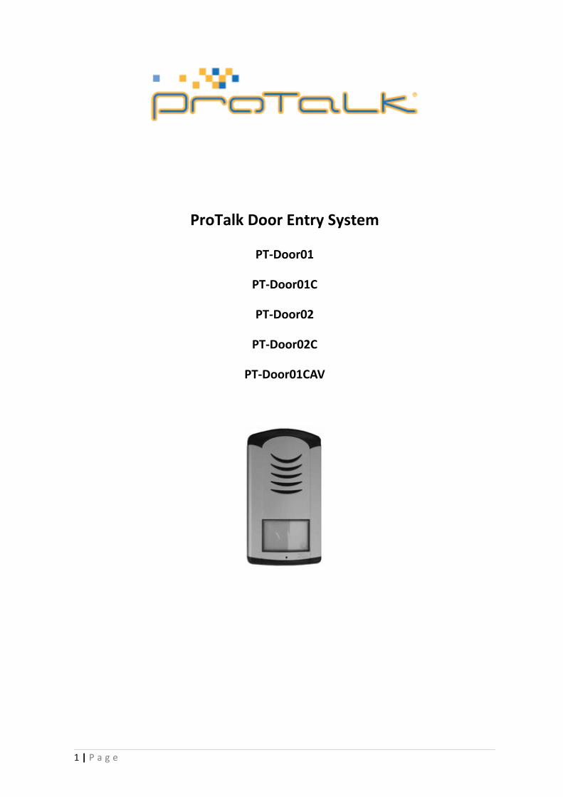
ProTalk Door Entry System
PT-Door01
PT-Door01C
PT-Door02
PT-Door02C
PT-Door01CAV
1 | P a g e
Installation and User Manual
WELCOME
Congratulations on purchasing the ‘ProTalk Door Entry’ system. This system will fulfil all your
business, and home, door entry communication needs. The ProTalk Door Entry system connects to
your computer network and allows either peer to peer (P2P) calls (calls direct to an IP address of
another VoIP device) or calls to another number via the SIP server.
There are several basic models to choose from; a one button system, a two buttons system or a
system with an integrated colour camera. There is also an Anti-vandal system in anodized
aluminium.
The unit is powered by either an AC/DC 12V power supply, which can also power an electric door
lock, or via a ‘Power over Ethernet’ (PoE) system.
The basic ProTalk Door Entry system includes an option to open, up to, two doors with electric
locks. The system is easily programmed via a user interface which is accessed via a web browser.
The manufacturer constantly improves the firmware of this product. The system can
download the latest version at any time with the help of an ordinary computer, the latest
firmware is available at http://protalk.provu.co.uk/firmware/
You will find the instructions how to do this on page 22 of this manual. We recommend that
you always download the latest version available to get the best out of the product features.
2 | P a g e
TABLE OF CONTENTS 1 BASIC DESCRIPTION 5
1.1 Features 5
1.2 Terminology 5
1.3 Modules 7
1.4 Unit features 7
1.4.1 Door Entry System - Basic Unit 7
1.5 Door Entry System assembly 11
1.5.1 Front cover assembly and disassembly 11
1.5.2 Name tag back lighting disassembly 12
1.5.3 Wall mounting 12
1.5.4 Return of name tags after wall mounting 13
1.5.5 Name tag change 13
2 DOOR ENTRY SYSTEM OPERATION 14
2.1 Signalling 14
2.2 Caller at the door 14
2.3 Person in the building 15
2.3.1 Outbound call 15
2.3.2 Incoming call 15
3 PARAMETER PROGRAMMING 16
3.1 Basic VoIP settings 16
3.1.1 Choice of mode and sign in 16
3.1.2 Language setting 17
3.1.3 Network settings 18
3.1.4 Peer to peer or SIP server connection 19
3.1.5 Audio codec setting 21
3.1.6 Video setting 22
3.1.7 Video viewing (programme Pop-Up) 22
3.1.8 Day intervals 23
3.1.9 User interface 24
3.1.10 Service settings 25
3.1.11 Restart 26
3.1.12 Preparation style, language support 26
3.2 Door Entry System parameter setting 27
3.2.1 Basic Parameters 27
3.2.2 All about relays 28
3.2.3 Time Parameters 30
3.2.4 Direct Dialling – Memory numbers 31
3 | P a g e

4 TECHNICAL PARAMETERS 32
4.1 Electrical parameters 32
4.2 Mechanical parameters 32
4.3 Video parameters 32
4 | P a g e
1 BASIC DESCRIPTION
1.1 Basic Features
Door Entry Control Unit:
• Buttons to dial extensions or groups;
• Options for single/double buttoned which call different numbers/groups
• Backlit buttons;
• Two internal SPDT relays for controlling a door opener or light etc.
• Relays controlled individually by DTMF tones; and
• SIP Protocol.
Unit with IP camera (as above with):
• Optional real-time IP camera viewed via a computer terminal;
• View and talk to callers as well as opening the door remotely; and
• Camera permanently operational, not just during calls.
ProTalk Support Kits:
• A range of electronically controlled door devices to connect to the door phone;
• 12v power supplies with battery backup option;
• Exit Relays; or
• Bundles [of above] as complete door entry kits.
1.2 Terminology
• Ethernet is a family of frame-based computer networking technologies for local area
networks (LANs).
• A local area network (LAN) is a computer network covering a small physical area, such as
home, office or small group of buildings, such as a school or an airport
• 10BASE-T runs over four wires (two twisted pairs) on a Category 3 or Category 5 cable.
• 100BASE-TX Uses two pairs, but requires Category 5 cable (FastEthernet)
• Twisted pair cabling is a form of wiring in which two conductors (the forward and return
conductors of a single circuit) are twisted together for the purposes of cancelling out
electromagnetic interference (EMI) from external sources.
5 | P a g e
• UTP (unshielded twisted pair) cable is not surrounded by any shielding.
• STP (shielded twisted pair) cables are often shielded in attempt to prevent electromagnetic
interference.
• The World Wide Web (commonly abbreviated as the "Web") is a system of interlinked
hypertext documents accessed via the Internet.
• Hypertext Transfer Protocol (HTTP) is an application-level protocol for distributed,
collaborative, hypermedia information systems.
• Universal Serial Bus (USB) is a serial bus standard to connect devices to a host computer.
• A video codec is a device or software that enables video compression and/or decompression
for digital video. H.264 is a standard for video compression, and is equivalent to MPEG-4 AVC.
H.263 is a video codec standard originally designed as a low-bitrate compressed format for
videoconferencing. MPEG-4 is collection of methods defining compression of audio and visual
(AV) digital data.
• JPEG is a commonly used method of compression for photographic images.
• Voice over Internet Protocol (VoIP) is a general term for a family of transmission
technologies for delivery of voice communications over IP networks such as the Internet.
• The Internet Protocol Suite (commonly known as TCP/IP) is the set of communications
protocols used for the Internet
• An Internet Protocol (IP) address is a numerical identification and logical address that is
assigned to devices participating in a computer network utilizing the Internet Protocol for
communication between its nodes.
• Dynamic Host Configuration Protocol (DHCP) is a network application protocol used by
devices (DHCP clients) to obtain configuration information for operation in an Internet
Protocol network.
• The Internet is a global system of interconnected computer networks that use the
standardized Internet Protocol Suite (TCP/IP).
• An intranet is a private computer network that uses Internet technologies
• Power over Ethernet or PoE technology describes a system to transfer electrical power, along
with data, to remote devices over standard twisted-pair cable in an Ethernet network
• Network Time Protocol (NTP), a means of synchronizing clocks over a computer network.
6 | P a g e
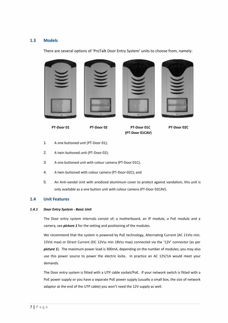
1.3 Models
There are several options of ‘ProTalk Door Entry System’ units to choose from, namely:
PT-Door 01 PT-Door 02 PT-Door 01C PT-Door 02C(PT-Door 01CAV)
1. A one buttoned unit (PT-Door 01);
2. A twin buttoned unit (PT-Door 02);
3. A one buttoned unit with colour camera (PT-Door 01C);
4. A twin buttoned with colour camera (PT-Door-02C); and
5. An Anti-vandal Unit with anodized aluminium cover to protect against vandalism, this unit is
only available as a one button unit with colour camera (PT-Door 02CAV).
1.4 Unit Features
1.4.1 Door Entry System - Basic Unit
The Door entry system internals consist of; a motherboard, an IP module, a PoE module and a
camera, see picture 1 for the setting and positioning of the modules.
We recommend that the system is powered by PoE technology, Alternating Current (AC 11Vts min.
15Vst max) or Direct Current (DC 12Vss min 18Vss max) connected via the ‘12V’ connector (as per
picture 1). The maximum power load is 300mA, depending on the number of modules; you may also
use this power source to power the electric locks. In practice an AC 12V/1A would meet your
demands.
The Door entry system is fitted with a UTP cable socket/PoE. If your network switch is fitted with a
PoE power supply or you have a separate PoE power supply (usually a small box, the size of network
adaptor at the end of the UTP cable) you won’t need the 12V supply as well.
7 | P a g e
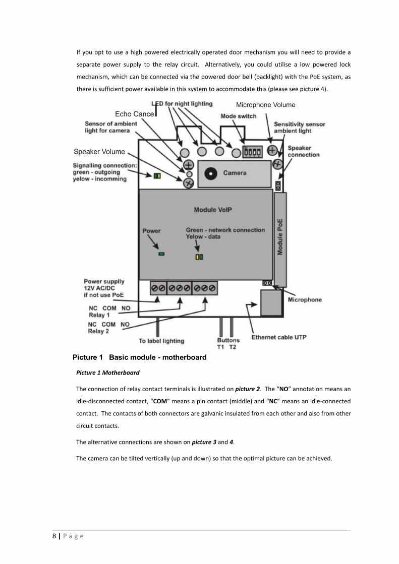
If you opt to use a high powered electrically operated door mechanism you will need to provide a
separate power supply to the relay circuit. Alternatively, you could utilise a low powered lock
mechanism, which can be connected via the powered door bell (backlight) with the PoE system, as
there is sufficient power available in this system to accommodate this (please see picture 4).
Picture 1 Motherboard
The connection of relay contact terminals is illustrated on picture 2. The “NO” annotation means an
idle-disconnected contact, “COM” means a pin contact (middle) and “NC” means an idle-connected
contact. The contacts of both connectors are galvanic insulated from each other and also from other
circuit contacts.
The alternative connections are shown on picture 3 and 4.
The camera can be tilted vertically (up and down) so that the optimal picture can be achieved.
8 | P a g e
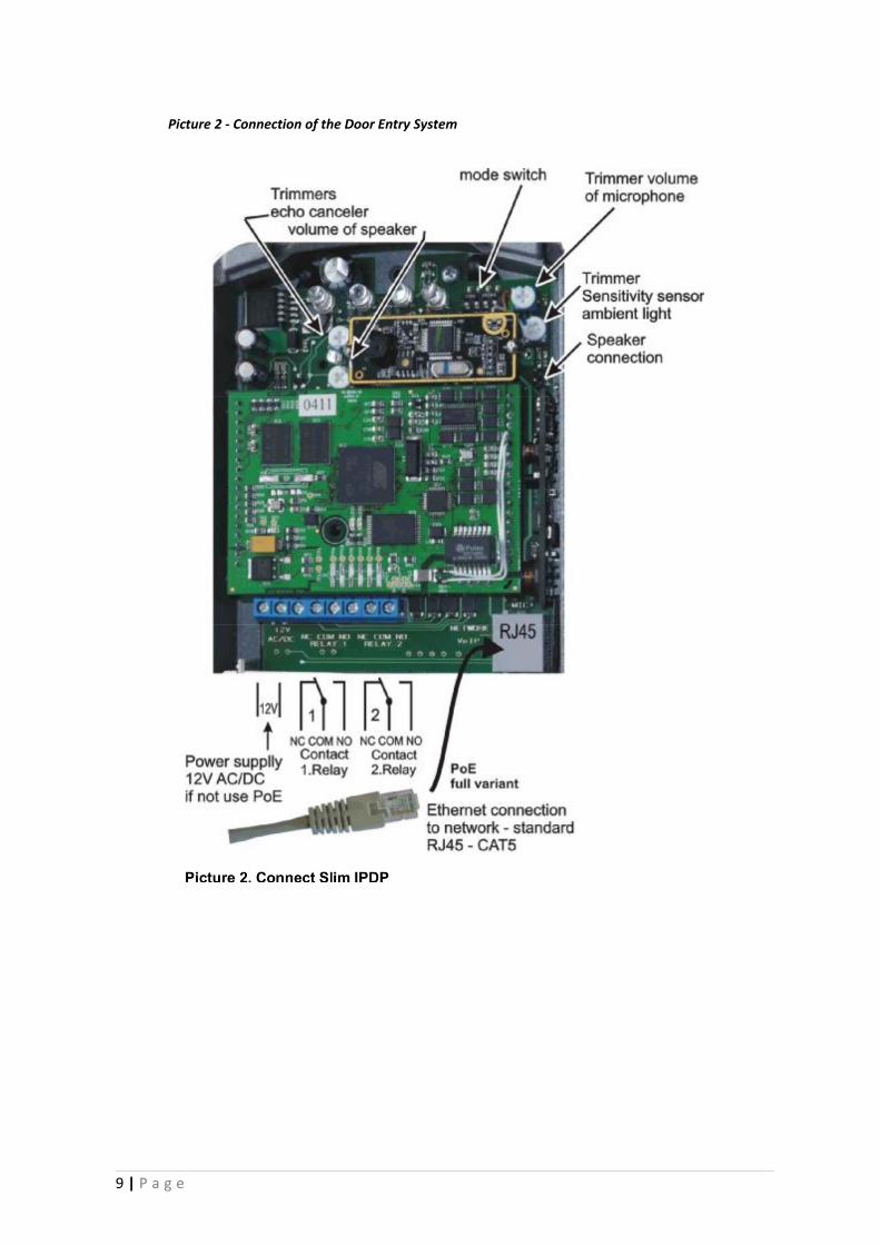
Picture 2 - Connection of the Door Entry System
9 | P a g e
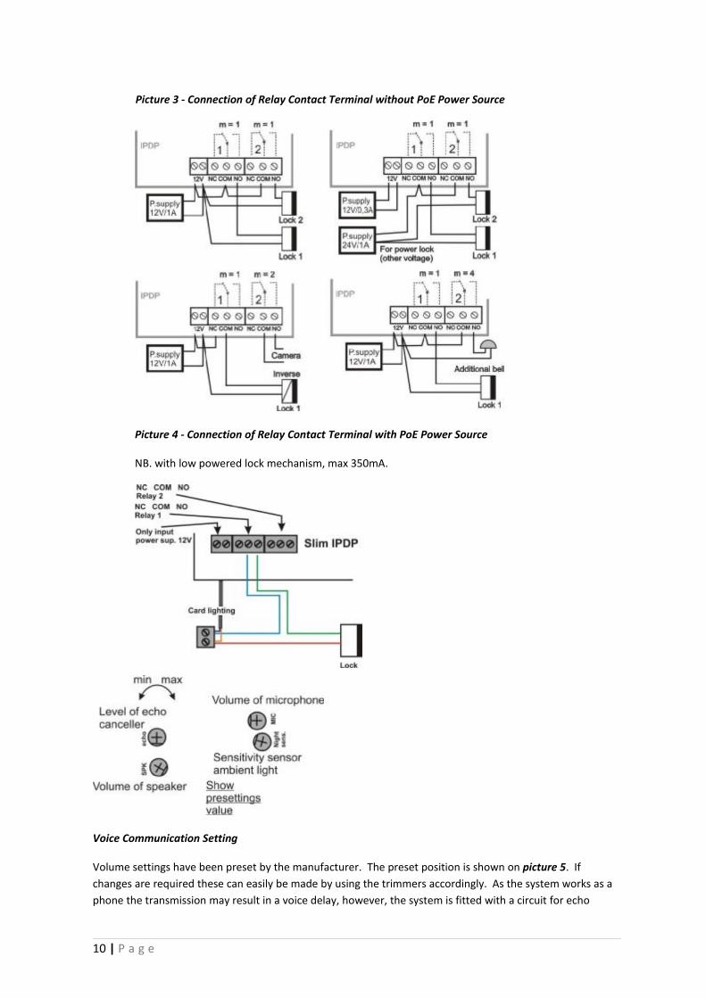
Picture 3 - Connection of Relay Contact Terminal without PoE Power Source
Picture 4 - Connection of Relay Contact Terminal with PoE Power Source
NB. with low powered lock mechanism, max 350mA.
Voice Communication Setting
Volume settings have been preset by the manufacturer. The preset position is shown on picture 5. If changes are required these can easily be made by using the trimmers accordingly. As the system works as a phone the transmission may result in a voice delay, however, the system is fitted with a circuit for echo
10 | P a g e
attenuation which can also be trimmed. The volume level is set such that the microphone will automatically switch off so that the voice does not result in an echo, see picture 5.
The light sensitivity trimmer allows you to set the level of light that triggers when the LED lights come on.
These lights shed additional lighting so that the camera will work at night. The light sensitive sensor is only
active during the call and automatically switches off at the end.
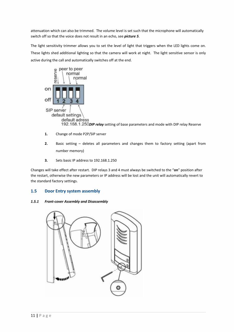
DIP relay setting of base parameters and mode with DIP relay Reserve
1. Change of mode P2P/SIP server
2. Basic setting – deletes all parameters and changes them to factory setting (apart from
number memory)
3. Sets basic IP address to 192.168.1.250
Changes will take effect after restart. DIP relays 3 and 4 must always be switched to the “on” position after the restart, otherwise the new parameters or IP address will be lost and the unit will automatically revert to the standard factory settings.
1.5 Door Entry system assembly
1.5.1 Front-cover Assembly and Disassembly
11 | P a g e
1.5.2 Name Tag Back Lighting Disassembly
1.5.3 Wall Mounting
The unit can be Wall mounted with the enclosed screws and wall plugs (screw driver diameter
5mm).
12 | P a g e
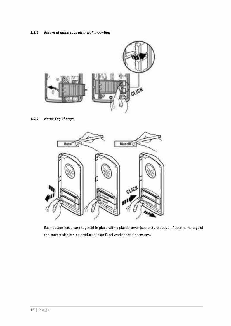
1.5.4 Return of name tags after wall mounting
1.5.5 Name Tag Change
Each button has a card tag held in place with a plastic cover (see picture above). Paper name tags of
the correct size can be produced in an Excel worksheet if necessary.
13 | P a g e
2 DOOR ENTRY SYSTEM OPERATION
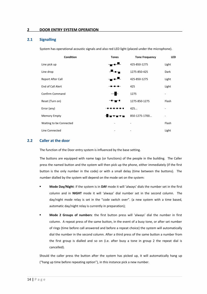
2.1 Signalling
System has operational acoustic signals and also red LED light (placed under the microphone).
Condition Tones Tone Frequency LED
Line pick up 425-850-1275 Light
Line drop 1275-850-425 Dark
Report After Call 425-850-1275 Light
End of Call Alert 425 Light
Confirm Command 1275 -
Reset (Turn on) 1275-850-1275 Flash
Error (any) 425... -
Memory Empty 850-1275-1700... -
Waiting to be Connected - - Flash
Line Connected - - Light
2.2 Caller at the door
The function of the Door entry system is influenced by the base setting.
The buttons are equipped with name tags (or functions) of the people in the building. The Caller
press the named button and the system will then pick up the phone, either immediately (if the first
button is the only number in the code) or with a small delay (time between the buttons). The
number dialled by the system will depend on the mode set on the system:
• Mode Day/Night: if the system is in DAY mode it will ‘always’ dials the number set in the first
column and in NIGHT mode it will ‘always’ dial number set in the second column. The
day/night mode relay is set in the “code switch over”. (a new system with a time based,
automatic day/night relay is currently in preparation);
• Mode 2 Groups of numbers: the first button press will ‘always’ dial the number in first
column. A repeat press of the same button, in the event of a busy tone, or after set number
of rings (time before call answered and before a repeat choice) the system will automatically
dial the number in the second column. After a third press of the same button a number from
the first group is dialled and so on (i.e. after busy a tone in group 2 the repeat dial is
cancelled).
Should the caller press the button after the system has picked up, it will automatically hang up
(“hang up time before repeating option”), in this instance pick a new number.
14 | P a g e
From the System dial it is possible to control the door relay (code lock). If the caller presses buttons
in the previously programmed combination and in a time previously set in the parameters, the
System will trip the appropriate relay (if it is set in modes m=1 to m=5) for a given time, previously
set in parameters.
2.3 Person(s) Inside the Building
‘Person(s) inside the building’ means anyone who is in telephone contact with the Door Entry
System.
2.3.1 Outbound Calls
An ‘outbound call’ is any call from the door entry System (i.e. from a visitor). When the phone rings
and is pick-up it will be possible to speak with the visitor at the door, by choosing one of the modes
(m=1 to m=5, Day/Night mode, hang up etc). 10 seconds into any conversation the system will issue
an end of call alert, by choosing ‘*/#’ it is possible to prolong the call; the call will then be ended by
hanging up.
There are two ways for information to be transmitted (door lock opening, Day/Night modes,
prolonging the call, command for hang-up etc); either by “RTP channel” or by “SIP info”, the variant
“in-band DTMF” isn’t available in this Door Entry System.
2.3.2 Incoming Calls
An ‘incoming call’ is call from the System (i.e. from a visitor). After selecting the number of the
branch or IP address where the system is connected, the System rings (and the LED light will flash).
After set number of rings the system will automatically pick up the call and it is then possible for the
visitor to speak. Otherwise the options are the same as with the outbound calls.
15 | P a g e
3 PARAMETER PROGRAMMING
3.1 Basic VoIP Settings
3.1.1 Choice of Mode and Sign-in
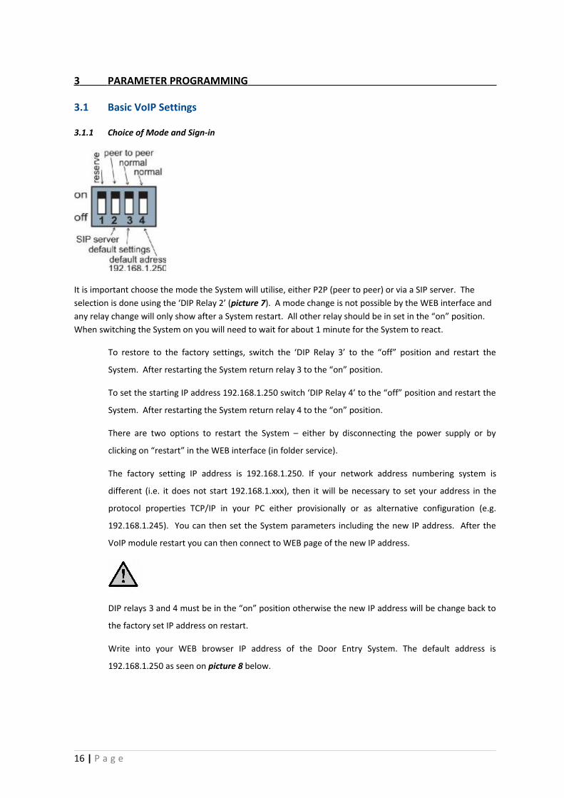
It is important choose the mode the System will utilise, either P2P (peer to peer) or via a SIP server. The selection is done using the ‘DIP Relay 2’ (picture 7). A mode change is not possible by the WEB interface and any relay change will only show after a System restart. All other relay should be in set in the “on” position. When switching the System on you will need to wait for about 1 minute for the System to react.
To restore to the factory settings, switch the ‘DIP Relay 3’ to the “off” position and restart the
System. After restarting the System return relay 3 to the “on” position.
To set the starting IP address 192.168.1.250 switch ‘DIP Relay 4’ to the “off” position and restart the
System. After restarting the System return relay 4 to the “on” position.
There are two options to restart the System – either by disconnecting the power supply or by
clicking on “restart” in the WEB interface (in folder service).
The factory setting IP address is 192.168.1.250. If your network address numbering system is
different (i.e. it does not start 192.168.1.xxx), then it will be necessary to set your address in the
protocol properties TCP/IP in your PC either provisionally or as alternative configuration (e.g.
192.168.1.245). You can then set the System parameters including the new IP address. After the
VoIP module restart you can then connect to WEB page of the new IP address.
DIP relays 3 and 4 must be in the “on” position otherwise the new IP address will be change back to
the factory set IP address on restart.
Write into your WEB browser IP address of the Door Entry System. The default address is
192.168.1.250 as seen on picture 8 below.
16 | P a g e
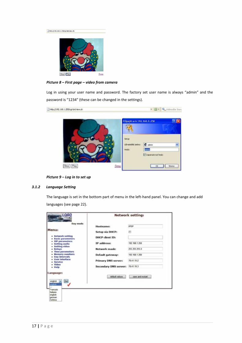
Picture 8 – First page – video from camera
Log in using your user name and password. The factory set user name is always “admin” and the
password is “1234” (these can be changed in the settings).
Picture 9 – Log in to set up
3.1.2 Language Setting
The language is set in the bottom part of menu in the left-hand panel. You can change and add
languages (see page 22).
17 | P a g e
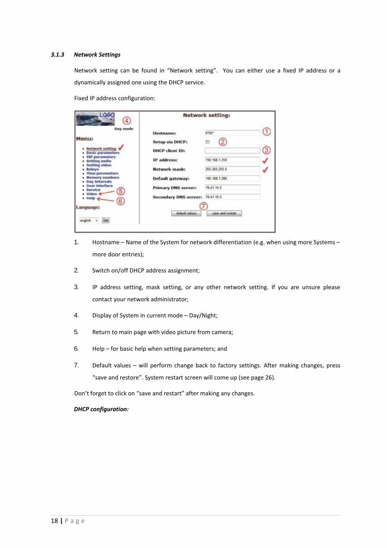
3.1.3 Network Settings
Network setting can be found in “Network setting”. You can either use a fixed IP address or a
dynamically assigned one using the DHCP service.
Fixed IP address configuration:
1. Hostname – Name of the System for network differentiation (e.g. when using more Systems –
more door entries);
2. Switch on/off DHCP address assignment;
3. IP address setting, mask setting, or any other network setting. If you are unsure please
contact your network administrator;
4. Display of System in current mode – Day/Night;
5. Return to main page with video picture from camera;
6. Help – for basic help when setting parameters; and
7. Default values – will perform change back to factory settings. After making changes, press
“save and restore”. System restart screen will come up (see page 26).
Don’t forget to click on “save and restart” after making any changes.
DHCP configuration:
18 | P a g e
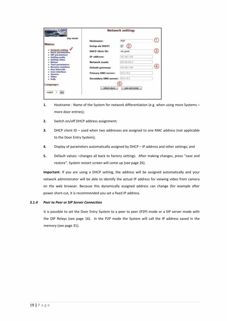
1. Hostname - Name of the System for network differentiation (e.g. when using more Systems –
more door entries);
2. Switch on/off DHCP address assignment;
3. DHCP client ID – used when two addresses are assigned to one MAC address (not applicable
to the Door Entry System);
4. Display of parameters automatically assigned by DHCP – IP address and other settings; and
5. Default values –changes all back to factory settings. After making changes, press “save and
restore”. System restart screen will come up (see page 26).
Important: If you are using a DHCP setting, the address will be assigned automatically and your
network administrator will be able to identify the actual IP address for viewing video from camera
on the web browser. Because this dynamically assigned address can change (for example after
power short-cut, it is recommended you set a fixed IP address.
3.1.4 Peer to Peer or SIP Server Connection
It is possible to set the Door Entry System to a peer to peer (P2P) mode or a SIP server mode with
the DIP Relays (see page 16). In the P2P mode the System will call the IP address saved in the
memory (see page 31).
19 | P a g e
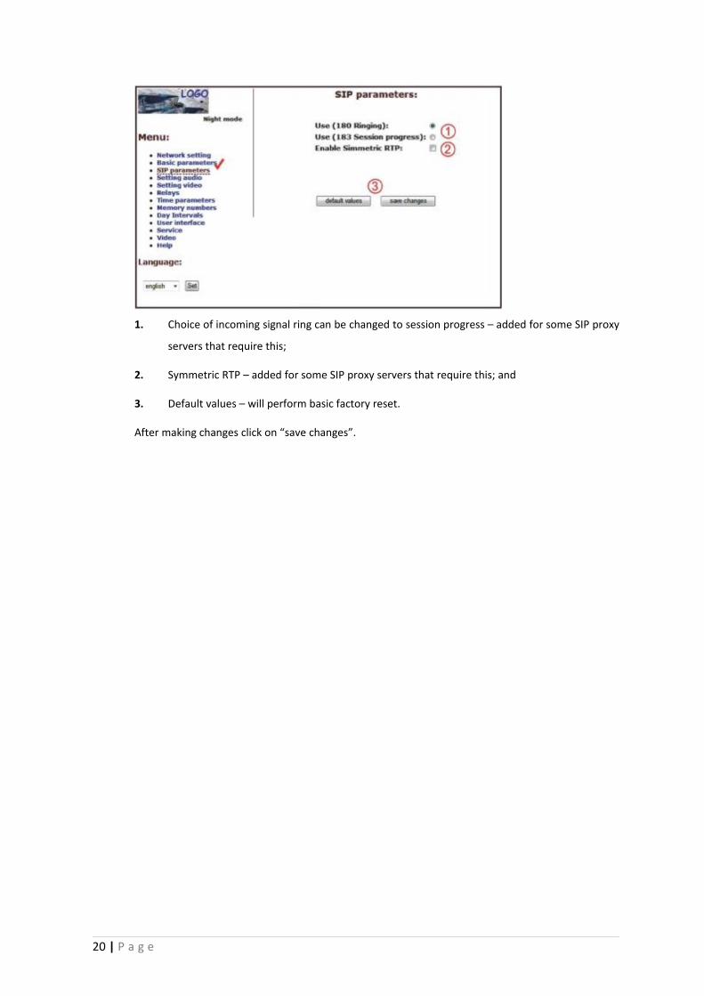
1. Choice of incoming signal ring can be changed to session progress – added for some SIP proxy
servers that require this;
2. Symmetric RTP – added for some SIP proxy servers that require this; and
3. Default values – will perform basic factory reset.
After making changes click on “save changes”.
20 | P a g e
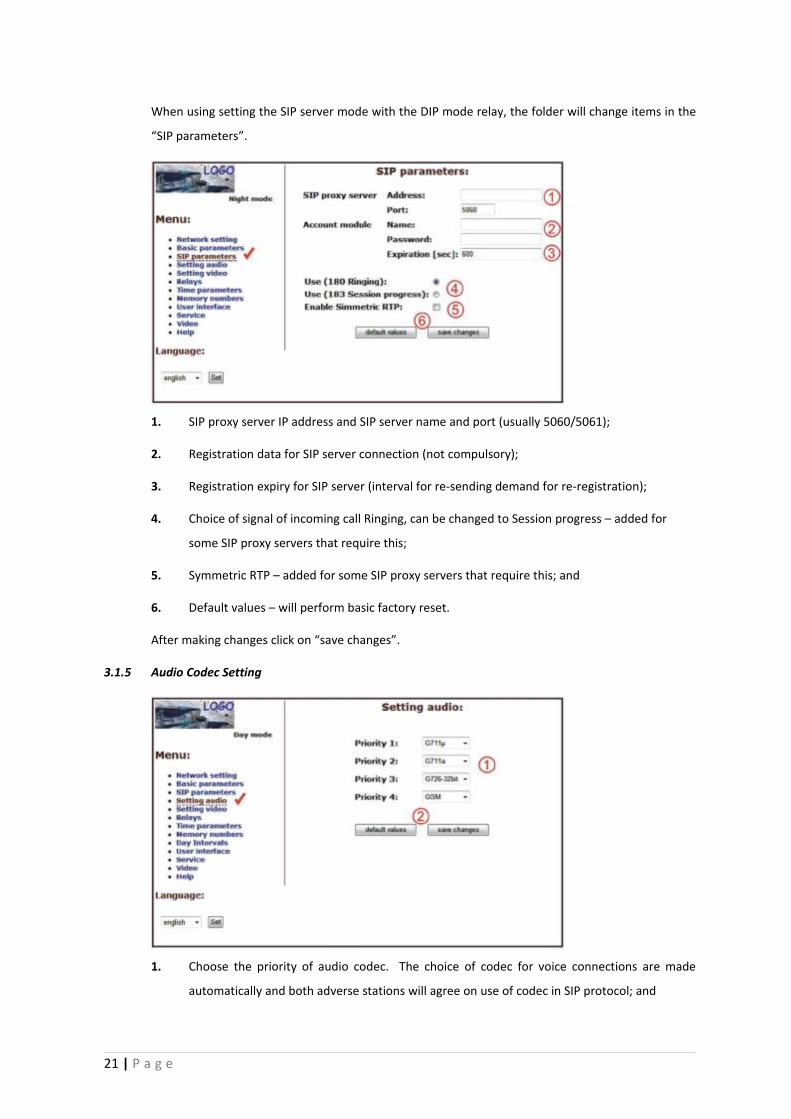
When using setting the SIP server mode with the DIP mode relay, the folder will change items in the
“SIP parameters”.
1. SIP proxy server IP address and SIP server name and port (usually 5060/5061);
2. Registration data for SIP server connection (not compulsory);
3. Registration expiry for SIP server (interval for re-sending demand for re-registration);
4. Choice of signal of incoming call Ringing, can be changed to Session progress – added for
some SIP proxy servers that require this;
5. Symmetric RTP – added for some SIP proxy servers that require this; and
6. Default values – will perform basic factory reset.
After making changes click on “save changes”.
3.1.5 Audio Codec Setting
1. Choose the priority of audio codec. The choice of codec for voice connections are made
automatically and both adverse stations will agree on use of codec in SIP protocol; and
21 | P a g e
2. Default values – will perform basic factory reset.
After making changes click on “save changes”.
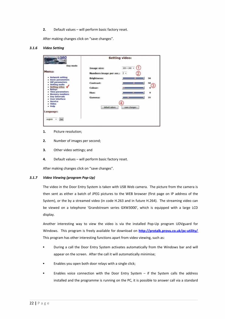
3.1.6 Video Setting
1. Picture resolution;
2. Number of images per second;
3. Other video settings; and
4. Default values – will perform basic factory reset.
After making changes click on “save changes”.
3.1.7 Video Viewing (program Pop-Up)
The video in the Door Entry System is taken with USB Web camera. The picture from the camera is
then sent as either a batch of JPEG pictures to the WEB browser (first page on IP address of the
System), or the by a streamed video (in code H.263 and in future H.264). The streaming video can
be viewed on a telephone ‘Grandstream series GXW3000’, which is equipped with a large LCD
display.
Another interesting way to view the video is via the installed Pop-Up program UDVguard for
Windows. This program is freely available for download on http://protalk.provu.co.uk/pc-utility/
This program has other interesting functions apart from video viewing, such as:
• During a call the Door Entry System activates automatically from the Windows bar and will
appear on the screen. After the call it will automatically minimise;
• Enables you open both door relays with a single click;
• Enables voice connection with the Door Entry System – if the System calls the address
installed and the programme is running on the PC, it is possible to answer call via a standard
22 | P a g e
PC sound card. By clicking on icon of the Door Entry System it is also possible to call the
System;
• The program can be installed on up to 100 PCs on the network. If the connection with the
System is active, the window with the video will appear on all of the PCs installed. In this
program the IP address of the System is set.
• You can run several Door Entry Systems in one network and the different Door Entry Systems
can be differentiated with a “nametag” (see page 18), the name can be shown in the header
of Pop-Up program.
Video parameters are explained on page 32.
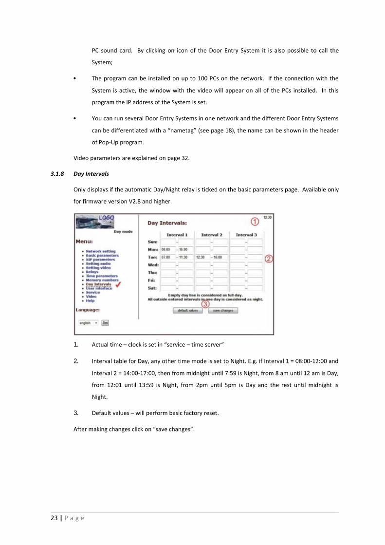
3.1.8 Day Intervals
Only displays if the automatic Day/Night relay is ticked on the basic parameters page. Available only
for firmware version V2.8 and higher.
1. Actual time – clock is set in “service – time server”
2. Interval table for Day, any other time mode is set to Night. E.g. if Interval 1 = 08:00-12:00 and
Interval 2 = 14:00-17:00, then from midnight until 7:59 is Night, from 8 am until 12 am is Day,
from 12:01 until 13:59 is Night, from 2pm until 5pm is Day and the rest until midnight is
Night.
3. Default values – will perform basic factory reset.
After making changes click on “save changes”.
23 | P a g e
3.1.9 User Interface
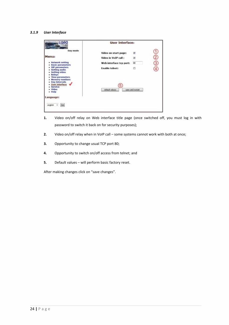
1. Video on/off relay on Web interface title page (once switched off, you must log in with
password to switch it back on for security purposes);
2. Video on/off relay when in VoIP call – some systems cannot work with both at once;
3. Opportunity to change usual TCP port 80;
4. Opportunity to switch on/off access from telnet; and
5. Default values – will perform basic factory reset.
After making changes click on “save changes”.
24 | P a g e
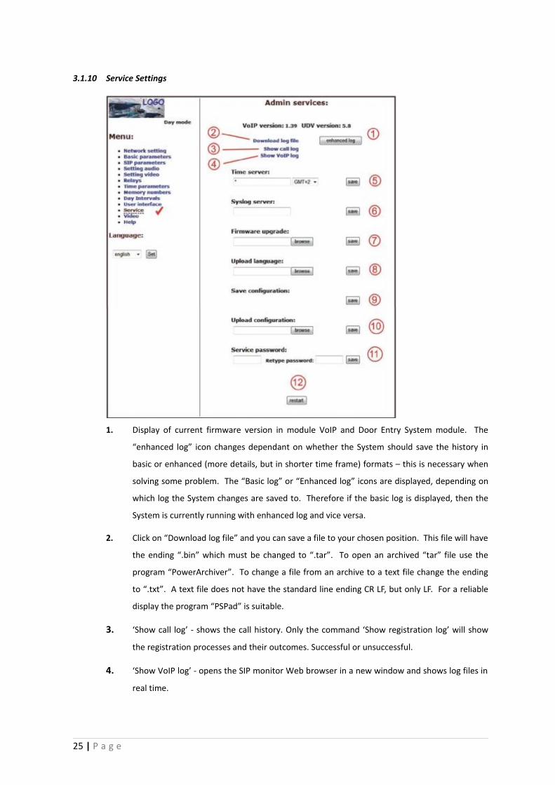
3.1.10 Service Settings
1. Display of current firmware version in module VoIP and Door Entry System module. The
“enhanced log” icon changes dependant on whether the System should save the history in
basic or enhanced (more details, but in shorter time frame) formats – this is necessary when
solving some problem. The “Basic log” or “Enhanced log” icons are displayed, depending on
which log the System changes are saved to. Therefore if the basic log is displayed, then the
System is currently running with enhanced log and vice versa.
2. Click on “Download log file” and you can save a file to your chosen position. This file will have
the ending “.bin” which must be changed to “.tar”. To open an archived “tar” file use the
program “PowerArchiver”. To change a file from an archive to a text file change the ending
to “.txt”. A text file does not have the standard line ending CR LF, but only LF. For a reliable
display the program “PSPad” is suitable.
3. ‘Show call log’ - shows the call history. Only the command ‘Show registration log’ will show
the registration processes and their outcomes. Successful or unsuccessful.
4. ‘Show VoIP log’ - opens the SIP monitor Web browser in a new window and shows log files in
real time.
25 | P a g e
5. IP address of NTP server – accurate time setting off the internet (automatic Day/Night mode
clock for registering log files to the ‘syslog’ server). If you don’t know the address, use * and
the system will select an appropriate address (input * and click on save).
6. Syslog server – IP address of server where system events are recorded (when syslog
application is running).
7. Latest firmware version upgrade for VoIP and Door Entry System modules. New firmware
upgrades will be automatically detected according to the file header. This can also be used to
download new graphic styles from the Web interface (i.e. colours, fonts, logos etc).
8. Upload language – uploads or rewrites language support files. It is not possible to edit the
two basic languages (Czech and English).
9. Save configuration – all files.
10. Restore configuration – restores parameters to previously settings.
11. Change access password, the default is 1234.
12. Restart VoIP module – necessary after firmware upgrade.
3.1.11 Restart
3.1.12 Preparation Style, Language Support
Style
The style file consists of three zipped files in the “.tar” archive. To unzip this “.tar” archive, use a
programme such as “PowerArchiver”.
The first file will be headed “upload_fw.sh”, please do not change this file.
The second file is in syntax HTML, and enables you to change fonts, font sizes, font colours and lines,
background colour etc. For a reliable display the “PSPad” programme would be suitable.
26 | P a g e
The third file is a picture (i.e. company logo). This file can be in either GIF or JPG format and up to
200x200px. in size. GIF files are more preferable with the background set to opaque (see through)
as this will enable you to eliminate any frame around the logo. Rename the picture file as
“logo.img”.
To zip the archive use the “PowerArchiver” program, by setting the “tared” option in the “tar”
archive.
Language support
A basic file, which allows the basic languages of English or Czech to be translated into other
languages. Any translation will also include Help text. The name of these files will be the name of
language; therefore do not use an extension for editing the name use the program “PSPad”. Only
translate the terms in quotation marks, and ensure that notations are kept in the HTML format.
3.2 Door Entry System parameter setting
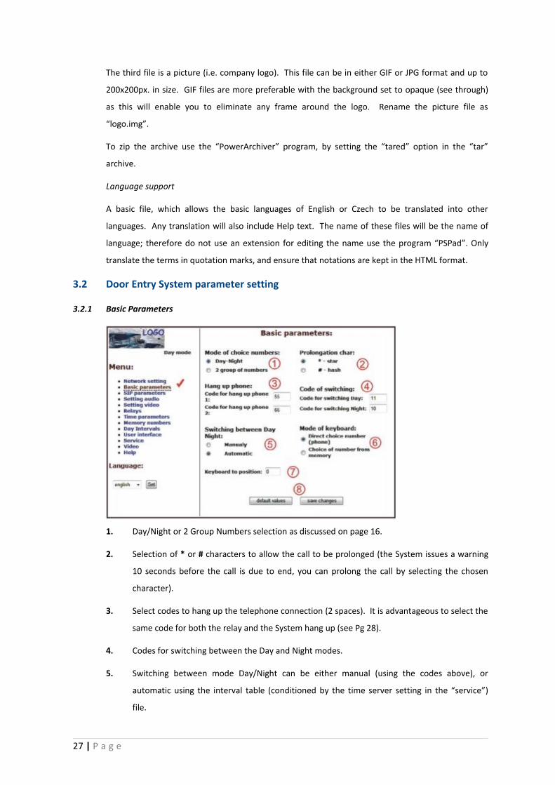
3.2.1 Basic Parameters
1. Day/Night or 2 Group Numbers selection as discussed on page 16.
2. Selection of * or # characters to allow the call to be prolonged (the System issues a warning
10 seconds before the call is due to end, you can prolong the call by selecting the chosen
character).
3. Select codes to hang up the telephone connection (2 spaces). It is advantageous to select the
same code for both the relay and the System hang up (see Pg 28).
4. Codes for switching between the Day and Night modes.
5. Switching between mode Day/Night can be either manual (using the codes above), or
automatic using the interval table (conditioned by the time server setting in the “service”)
file.
27 | P a g e
6. NOT USED in this version of the Door Entry System.
7. NOT USED in this version of the Door Entry System.
8. Default values – will perform basic factory reset.
After making changes don’t forget to click on “save changes.
Setting these parameters may fundamentally changes the functions of the System.
3.2.2 All about Relays
1. Relay modes:
=1 Switch mode –switches on by either command or password for a given time, set in
“relay closing” (used for electric locks, gate opening etc);
=2 Camera mode – switches the camera on when the System is activated and off
when the connection is terminated (hung up).
=3 Light mode – switches the LED light on when the System is activated (pick up) for
specified time (as set in “relay closing”).
28 | P a g e
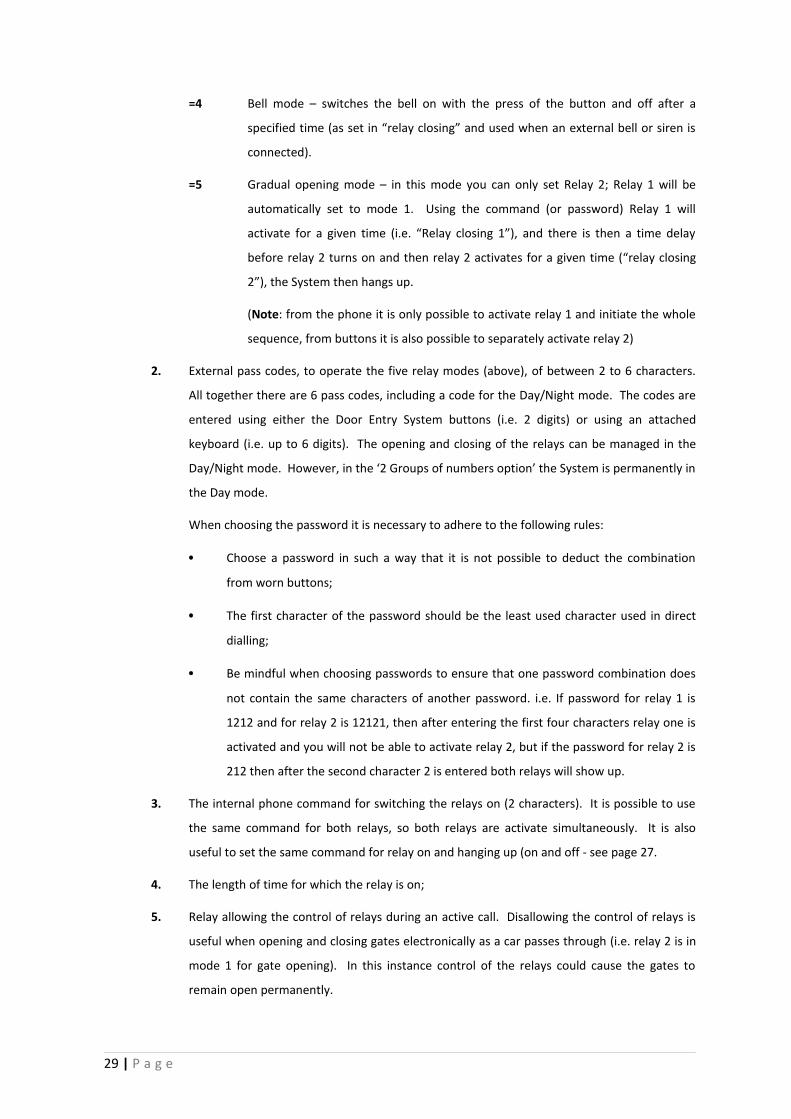
=4 Bell mode – switches the bell on with the press of the button and off after a
specified time (as set in “relay closing” and used when an external bell or siren is
connected).
=5 Gradual opening mode – in this mode you can only set Relay 2; Relay 1 will be
automatically set to mode 1. Using the command (or password) Relay 1 will
activate for a given time (i.e. “Relay closing 1”), and there is then a time delay
before relay 2 turns on and then relay 2 activates for a given time (“relay closing
2”), the System then hangs up.
(Note: from the phone it is only possible to activate relay 1 and initiate the whole
sequence, from buttons it is also possible to separately activate relay 2)
2. External pass codes, to operate the five relay modes (above), of between 2 to 6 characters.
All together there are 6 pass codes, including a code for the Day/Night mode. The codes are
entered using either the Door Entry System buttons (i.e. 2 digits) or using an attached
keyboard (i.e. up to 6 digits). The opening and closing of the relays can be managed in the
Day/Night mode. However, in the ‘2 Groups of numbers option’ the System is permanently in
the Day mode.
When choosing the password it is necessary to adhere to the following rules:
• Choose a password in such a way that it is not possible to deduct the combination
from worn buttons;
• The first character of the password should be the least used character used in direct
dialling;
• Be mindful when choosing passwords to ensure that one password combination does
not contain the same characters of another password. i.e. If password for relay 1 is
1212 and for relay 2 is 12121, then after entering the first four characters relay one is
activated and you will not be able to activate relay 2, but if the password for relay 2 is
212 then after the second character 2 is entered both relays will show up.
3. The internal phone command for switching the relays on (2 characters). It is possible to use
the same command for both relays, so both relays are activate simultaneously. It is also
useful to set the same command for relay on and hanging up (on and off - see page 27.
4. The length of time for which the relay is on;
5. Relay allowing the control of relays during an active call. Disallowing the control of relays is
useful when opening and closing gates electronically as a car passes through (i.e. relay 2 is in
mode 1 for gate opening). In this instance control of the relays could cause the gates to
remain open permanently.
29 | P a g e
6. Time delay between relay closing 1 and 2 in mode m=5 (gradual opening) [2 characters 01-99]
7. Default values – will perform basic factory reset.
After making any changes click on “save changes”.
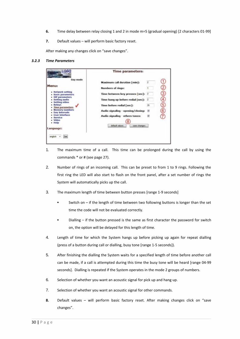
3.2.3 Time Parameters
1. The maximum time of a call. This time can be prolonged during the call by using the
commands * or # (see page 27).
2. Number of rings of an incoming call. This can be preset to from 1 to 9 rings. Following the
first ring the LED will also start to flash on the front panel, after a set number of rings the
System will automatically picks up the call.
3. The maximum length of time between button presses [range 1-9 seconds]
• Switch on – if the length of time between two following buttons is longer than the set
time the code will not be evaluated correctly.
• Dialling – if the button pressed is the same as first character the password for switch
on, the option will be delayed for this length of time.
4. Length of time for which the System hangs up before picking up again for repeat dialling
(press of a button during call or dialling, busy tone [range 1-5 seconds]).
5. After finishing the dialling the System waits for a specified length of time before another call
can be made, if a call is attempted during this time the busy tone will be heard [range 04-99
seconds]. Dialling is repeated if the System operates in the mode 2 groups of numbers.
6. Selection of whether you want an acoustic signal for pick up and hang up.
7. Selection of whether you want an acoustic signal for other commands.
8. Default values – will perform basic factory reset. After making changes click on “save
changes”.
30 | P a g e
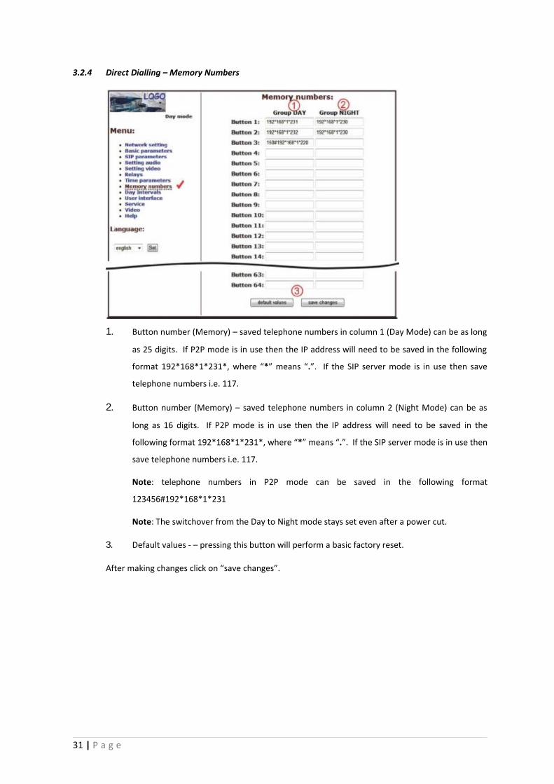
3.2.4 Direct Dialling – Memory Numbers
1. Button number (Memory) – saved telephone numbers in column 1 (Day Mode) can be as long
as 25 digits. If P2P mode is in use then the IP address will need to be saved in the following
format 192*168*1*231*, where “*” means “.”. If the SIP server mode is in use then save
telephone numbers i.e. 117.
2. Button number (Memory) – saved telephone numbers in column 2 (Night Mode) can be as
long as 16 digits. If P2P mode is in use then the IP address will need to be saved in the
following format 192*168*1*231*, where “*” means “.”. If the SIP server mode is in use then
save telephone numbers i.e. 117.
Note: telephone numbers in P2P mode can be saved in the following format
123456#192*168*1*231
Note: The switchover from the Day to Night mode stays set even after a power cut.
3. Default values - – pressing this button will perform a basic factory reset.
After making changes click on “save changes”.
31 | P a g e
4 TECHNICAL PARAMETERS
4.1. Electric Parameters
4.2. Mechanical Measurements
The covers of all the Door Entry System covers are IP44 to protect against water intrusion.
4.3. Video Parameters
Video for WEB
Internet Explorer - (series of JPEG pictures-Port 80) uses constantly repeated http request
address/video.jpg.
Mozilla, Opera, Firefox (a program PopUp, UDVguard) – (MJPEG stream – Port80) uses http
request address/video.mjpg (sometimes it is necessary to reload before it starts running properly).
These browsers are preferable to Internet Explorer because the video viewing is smoother and has
less impact on the network load.
Streaming video for IP phones
• H.263 formatting is set automatically between the Door Entry System and the videophone via
a SIP/SDP protocol on a standard SIP port and video (and sound) which then runs via RTP
protocol on ports agreed via SIP (usually 9078).
Video parameters
• JPG pictures are created in the camera and for all transmitting protocols are the same.
• The size (resolution) of video is selected in “Video setting” on the WEB.
• Maximum size depends on the USB camera type but is usually 640x480.
32 | P a g e
• Streaming H.263 only recognises CIF resolution (352x288) so bigger JPEGs will be reduced to
fill the screen however; smaller JPEGs will not be increased to fill the screen.
• JPG picture count (1-4 pictures/second) is set in “Video setting” on the WEB.
• The picture count of both MJPG and Stream H.263 is set by the camera type used however
this is normally between 7-12 pictures/second.
Ports
• Port 80 for http (WEB pages and JPG/MJPG on them).
• Port 5060 for SIP.
• Ports RTP are agreed with opposite side via SIP, usually is selected Port 7078 for audio and
Port 9078 for video.
33 | P a g e
WARRANTY
Each and every product has been tested before it leaves the factory.
The manufacturer guarantees that the product and its features will work in accordance with description in
this manual as long as the customer uses the product in accordance with the manufacturer’s instructions.
Warranties will be extended when a warranty repair has been undertaken.
Although all warranty repairs will be handled by the manufacturer it is important that warranty claims are
handled through your dealer. Warranty claims should be accompanied by;
• The product in question;
• a description of the problem;
• proof of purchase; and
• your full name and address.
The warranty does not cover:
• Mechanical, chemical, thermal or any other faults caused by the user;
• Faults caused by natural disasters;
• Faults caused by repairs or changes made by the user or any other authorised or unauthorised
person(s);
• Purposely done damage;
• Incorrect use of the product, caused by incorrect installation, programming etc; and
• Damages caused during the transport of the product to and from the purchaser.
Manufacturer:
Dealer:
Date of sale:
34 | P a g e


![PT Programming Manual - Voice Communications Inc. · PT Programming Manual. Introduction About this Programming Manual ... [006] Operator Assignment ... 22 [207] Door Unlock](https://img.pdfslide.net/doc/110x75/5ad2aba37f8b9a72118d679b/pt-programming-manual-voice-communications-inc-programming-manual-introduction.jpg)