Embed Size (px)
Citation preview
MSG 075 (11-0688) - GAP FILLER REMOVAL TASK SUMMARY NOTES Page 1 of 12
Page 1 of 12, MSG 075 (11-0688)
EVA Information for Gap Filler Task I. Background
We have been looking at the 2 protruding gap filler locations near the nose and working on a plan for how best to eliminate them, if required. Here is some background information, a brief summary of our evaluations thus far and some big picture words on our gap filler removal plan if it had to be implemented.
Protruding Gap Fillers The gap fillers protruding from both the port and stbd locations are the Ames type gap filler which is a thin layer (~0.020 in) of Nextel fabric coated with a light gray ceramic material. It is fairly flexible with a brittle coating. These gap fillers are bonded to the filler bar (pad bonded to Orbiter surface between tile gaps) with red RTV adhesive. The gap fillers are installed with one to five fillers per gap. When multiple gap fillers are used, the gap fillers are first bonded to each other and then bonded between the tiles. Because there is a small bond area and the gap filler has to match the exact curvature of the OML to produce a strong bond, it is not uncommon for an occasional gap filler to release and protrude a small amount. Tiles around the nose landing gear region “chatter” during ascent which further strains the bond and increases the chance of gap filler protrusion. Ground Experience with Protruding Gap Fillers Post flight experience with protruding Ames gap fillers has shown that these gap fillers typically release (pull-free) with 1 lb or less. Thermal environment affects the tile gaps and can affect the ease of removing the gap filler. When the Orbiter’s skin is colder, it
Protruding Gap Fillers
Figure 1 Location Overview
MSG 075 (11-0688) - GAP FILLER REMOVAL TASK SUMMARY NOTES Page 2 of 12
Page 2 of 12, MSG 075 (11-0688)
shrinks, pulling the tiles and gaps closer together. Discovery’s skin temperature is around 24F which is believed to be fairly benign, so it is believed that the gap fillers can be pulled out easily.
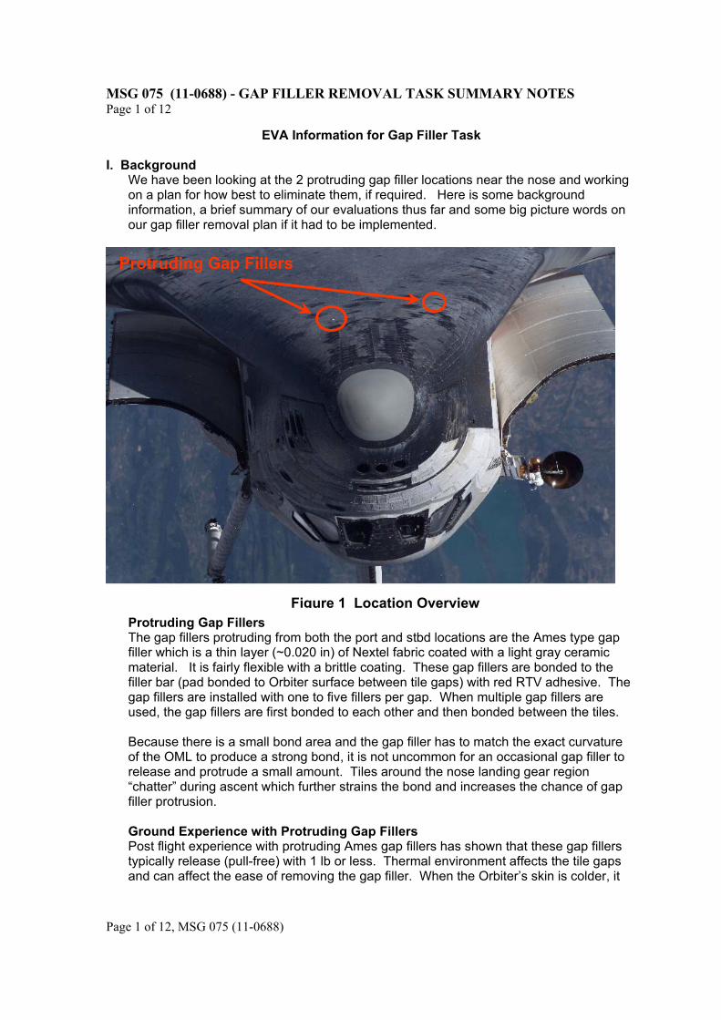
II. Port (Triangular) Gap Filler Site Details
This site is 4 tiles aft of the port edge of the NLGD. The protruding gap filler is a single layer, ~1.9 in x 3.0 in and has the port corner protruding ~1.1 in above the tile. There is a ceramic shim (tile extension) bonded to the tile that’s on the aft side of the protruding gap filler. Originally we thought the shim was protruding, but after closer inspection we are confident it is the gap filler only and the shim is still attach to the tile on it’s aft side (tile number -327).
FWD
PORT
Ceramic Shim 0.080 in thick attached to -327 tile
Protruding Gap Filler Single layer 1.9 in x 3.0 in
(protruding by 1.1 in)
Gap Filler – 1 layer (not attached to protruding gap filler)
When cutting, stroke ONLY in aft direction, pushing shim towards tile
391035 071
391035 327
MSG 075 (11-0688) - GAP FILLER REMOVAL TASK SUMMARY NOTES Page 3 of 12
Page 3 of 12, MSG 075 (11-0688)
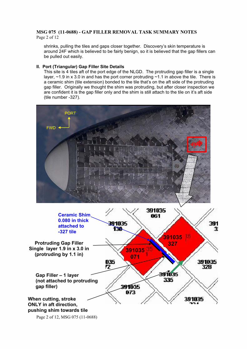
Figure 3 Port Gap Filler Close Up View III. Starboard Chine (Rectangular) Gap Filler Details
The starboard chine location is estimated to have 3 or 4 gap fillers. Because multiple gap fillers are bonded together, protrusions in these regions usually include the entire group of gap fillers. It is suspected that all of the gap fillers in this region are protruding,
Protruding Gap Filler 1 layer 1.9 in x 3.0 in
Cut ONLY in this direction
Ground Repair (dark area on corner of tile)
Figure 2: Port Gap Filler Location and Tile Layout View from EV APFR perspective
Fwd
MSG 075 (11-0688) - GAP FILLER REMOVAL TASK SUMMARY NOTES Page 4 of 12
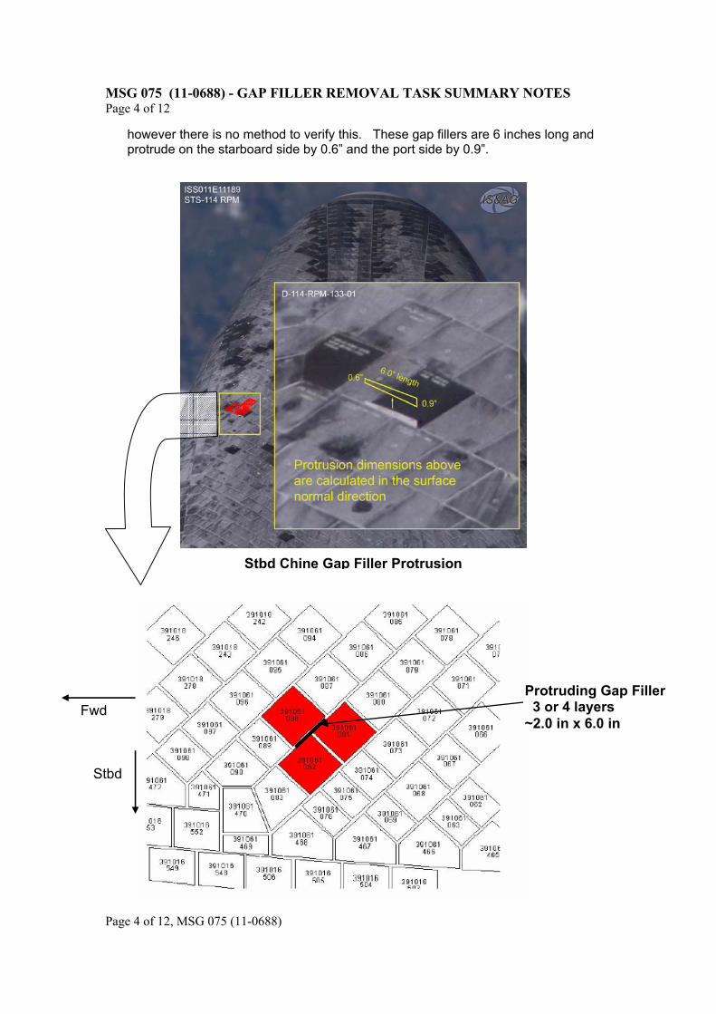
Page 4 of 12, MSG 075 (11-0688)
however there is no method to verify this. These gap fillers are 6 inches long and protrude on the starboard side by 0.6” and the port side by 0.9”.
Fwd
Stbd
Stbd Chine Gap Filler Protrusion
Protruding Gap Filler 3 or 4 layers ~2.0 in x 6.0 in
MSG 075 (11-0688) - GAP FILLER REMOVAL TASK SUMMARY NOTES Page 5 of 12
Page 5 of 12, MSG 075 (11-0688)
IV. EVA Removal of Protruding Gap Fillers – General Information 1. As you can imagine, we’ve put a lot of thought into whether to pull, push, or cut the gap
fillers. We think the gap fillers should pull out easily. Although pushing might also be easy, we think that if you push the gap filler in, it might come out again before/during entry even if it is currently in tightly (due to thermal fluctuations in the orbiter structure). Therefore, the preference and order for removing the gap filler protrusion is:
a. Remove the gap filler by pulling using fingers b. Remove the gap filler using EVA forceps c. Cut the gap filler using a gap filler cutter (modified IFM hacksaw) d. Last resort (gap filler cutter lost or broken): Cut the gap filler using the EVA
scissors (from EMU LTA pocket) and try to push in any excess with finger. 2. This task will require one EV on the SSRMS. The SSRMS is planned to be based from
MBS WS4 which provides good access and clearance. The SSRMS wraps around from the stbd side of the orbiter and gives access to both the stbd and port gap fillers. We do not want the free-floater on the SSRMS due to concerns with incidental TPS contact.
3. You should have good EV comm under the orbiter through ISS UHF. Comm to the shuttle IVA crew will be via hardline (docked icom) from ISS. A separate note will address the specific comm configuration. To be conservative, we want you to provide frequent comm with the SSRMS operator or GCA with comments like ‘move me in 1 foot’, etc. The frequent comm will allow for quickly identifying a loss of comm followed by stopping SSRMS motion.
4. WVS from shuttle is unliklely. We may have some WVS from ISS. The plan is to have helmet cameras controlled from ISS. We will have you pre-configure the WVS for the task before going under the orbiter.
5. We have done a 1G evaluation of the gap filler task (MOD, Dave Wolf, Joe Tanner, Jerry Ross, Scott Parazynski, TPS experts, etc.), some thermal testing of the modified hacksaw tool and we are in the process of performing an NBL run with the 121 crew. The task itself should be fairly simple and straightforward assuming the configuration of the gap fillers is as we expect. Even if cutting is required, the task is not too difficult.
6. In order to protect the tiles from inadvertent tool contact, we are trying to minimize the quantity of tools you need to wear, making your MWS as clean as possible. In addition, the SSRMS position and your body position will be optimized your body to avoid tool contact with the TPS.
7. Retaining the gap filler (with fingers or forceps) or gap filler pieces if cut and putting it in the trash bag is desired. However, we understand that it might not be possible Loss of this debris is acceptable and will not cause a re-contact or significant debris concern.
8. A small amount of fine powder and small fibers are expected to come off when sawing. This is only about 1/8th of a teaspoon total. In the event that it clings to your gloves (static electricity generated by the sawing), we’ll have a recommendation for wiping the gloves either EVA or IVA (with wet wipes) to prevent free fibers in the cabin. The fibers are a skin irritant in smaller quantities and an inhalant irritant in large quantities. It is highly unlikely that the cabin quantity will be significant enough to cause an inhalant irritant.
8. Expected new pre-EVA 3 tasks:
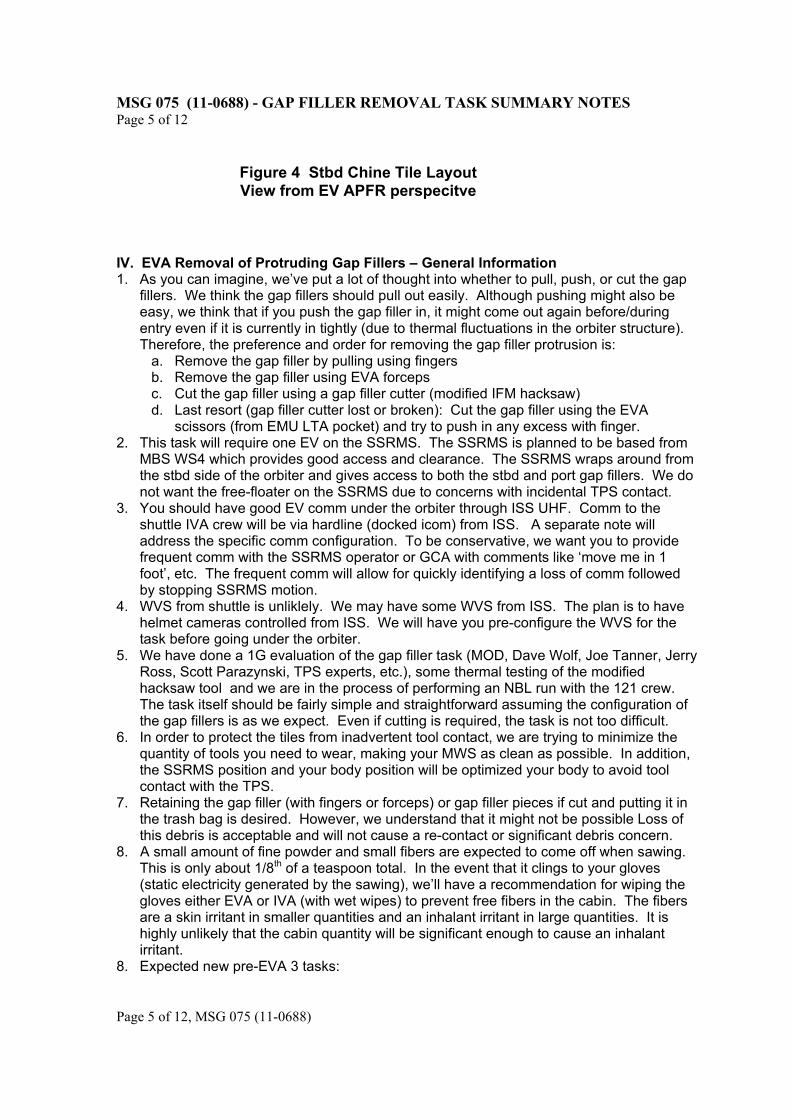
Figure 4 Stbd Chine Tile Layout View from EV APFR perspecitve
MSG 075 (11-0688) - GAP FILLER REMOVAL TASK SUMMARY NOTES Page 6 of 12
Page 6 of 12, MSG 075 (11-0688)
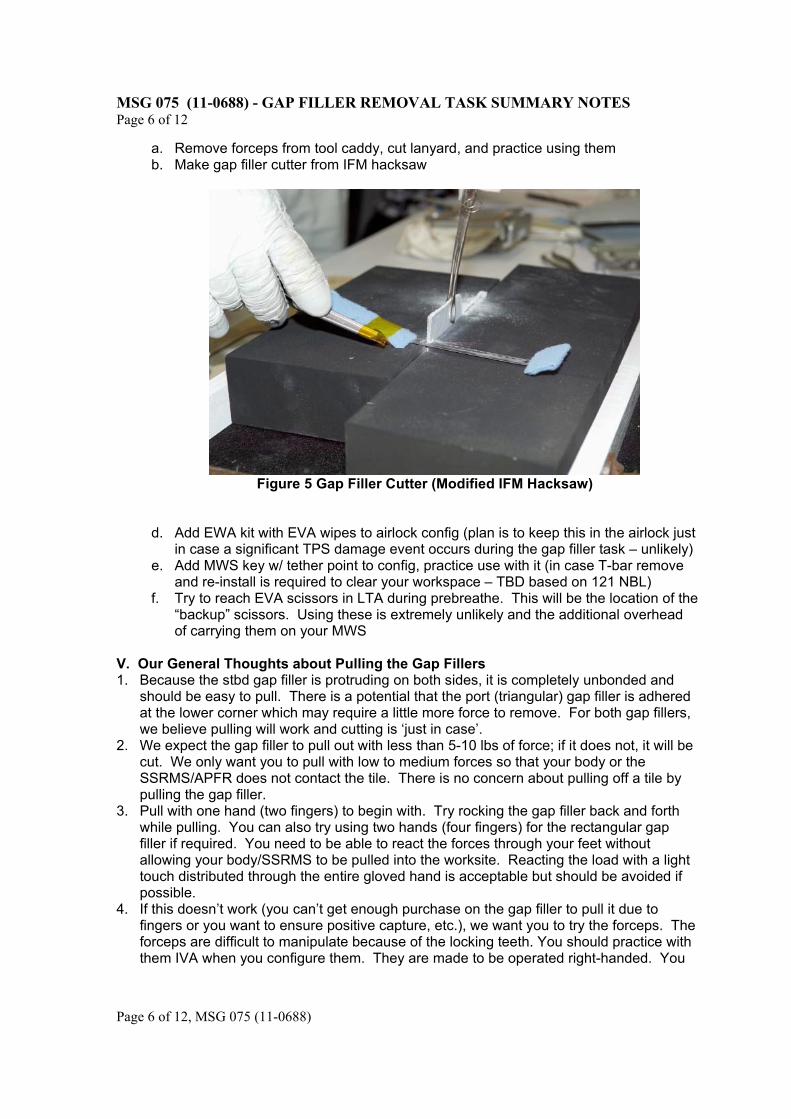
a. Remove forceps from tool caddy, cut lanyard, and practice using them b. Make gap filler cutter from IFM hacksaw
Figure 5 Gap Filler Cutter (Modified IFM Hacksaw)
d. Add EWA kit with EVA wipes to airlock config (plan is to keep this in the airlock just in case a significant TPS damage event occurs during the gap filler task – unlikely)
e. Add MWS key w/ tether point to config, practice use with it (in case T-bar remove and re-install is required to clear your workspace – TBD based on 121 NBL)
f. Try to reach EVA scissors in LTA during prebreathe. This will be the location of the “backup” scissors. Using these is extremely unlikely and the additional overhead of carrying them on your MWS
V. Our General Thoughts about Pulling the Gap Fillers 1. Because the stbd gap filler is protruding on both sides, it is completely unbonded and
should be easy to pull. There is a potential that the port (triangular) gap filler is adhered at the lower corner which may require a little more force to remove. For both gap fillers, we believe pulling will work and cutting is ‘just in case’.
2. We expect the gap filler to pull out with less than 5-10 lbs of force; if it does not, it will be cut. We only want you to pull with low to medium forces so that your body or the SSRMS/APFR does not contact the tile. There is no concern about pulling off a tile by pulling the gap filler.
3. Pull with one hand (two fingers) to begin with. Try rocking the gap filler back and forth while pulling. You can also try using two hands (four fingers) for the rectangular gap filler if required. You need to be able to react the forces through your feet without allowing your body/SSRMS to be pulled into the worksite. Reacting the load with a light touch distributed through the entire gloved hand is acceptable but should be avoided if possible.
4. If this doesn’t work (you can’t get enough purchase on the gap filler to pull it due to fingers or you want to ensure positive capture, etc.), we want you to try the forceps. The forceps are difficult to manipulate because of the locking teeth. You should practice with them IVA when you configure them. They are made to be operated right-handed. You
MSG 075 (11-0688) - GAP FILLER REMOVAL TASK SUMMARY NOTES Page 7 of 12
Page 7 of 12, MSG 075 (11-0688)
need to squeeze them together and engage the tightest locking setting, then use the rings to pull (versus continuing to squeeze the handle). The gap filler will stay in their grips for something on the order of 10 -15 lbs worth of force until they slip off (with the tightest lock setting). If pulling doesn’t work, we’ll have you cut it.
VI. Our General Thoughts about Cutting the Gap Fillers 1. The goal is to get the gap filler such that it isn’t protruding more than ¼-inch (under
review to increase this). Several tools were evaluated and the Gap Filler Cutting tool (modified IFM hacksaw) was selected for producing a close cut and ease of use. Multiple subjects performed the cutting (with 4 layers) and consistently achieved between 0.03 and 0.10 inches of protuberance. Because the hacksaw method of cutting is repeatable and straightforward, a post cut measurement via EV is not required.
2. The serrated edge of the Gap Filler Cutting tool WILL nick the EMU gloves if enough pressure and a swiping motion is used (incidental contact and light sawing doesn’t knick an EMU swatch of RTV). Even if the RTV were nicked, it is not credible to cause enough damage to create a glove leak. Needless to say, do not grip the serrated parts or touch the blade.
3. The tile RCG is pretty robust (doesn’t tend to chip) when sawing over it with the blade flat. Note that the modified hacksaw will have a 10 to 15 degree bend which provides you with gloved hand clearance and allows you to keep the blade level with the tile OML. See video at C:\OCA-UP\OTHER\Saw_on_RCG.wmv. The most likely means for chipping the RCG is if the blade is angled (serrated edge towards tile) and pulled across a damaged RCG location (could snag RCG and cause additional chipping). Survey the tiles for an obvious step and avoid directly sawing into the side of a tile. It is easy to slightly change the blade’s angle of attack to avoid the tile step. Steps in these regions are expected to be around 0.030 (very small).
4. It is really easy to cut the single (triangle) gap filler and the saw should go through it very quickly. The thicker (rectangular) gap filler that is 3-4 layers thick will take more strokes.
5. When sawing, longer strokes are better. Joe T. suggested that you could try for a cleaner cut (fewer dangling fibers) with smaller strokes as you near the end of the cut.
VII. Other General Thoughts
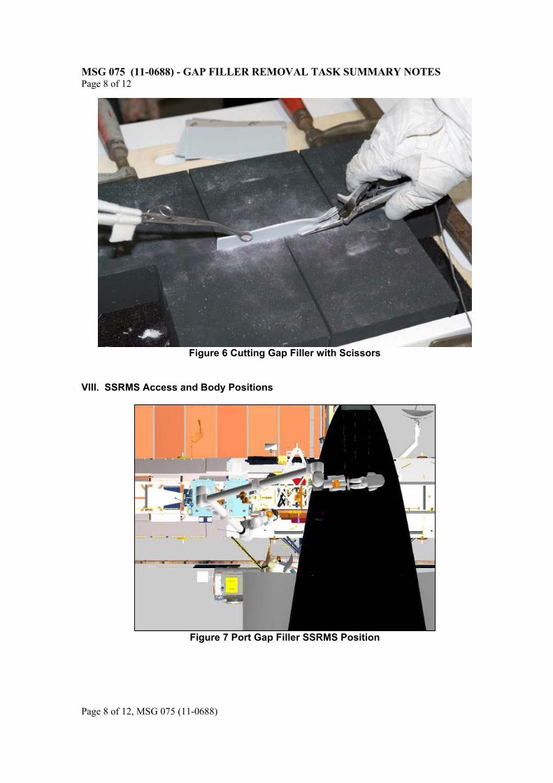
1. EMU Scissors - The hacksaw has performed well in testing, so we don’t really think you will need to use the scissors. But, in case you do, here’s what to expect:
a. Scissors cannot cut as close as the gap filler cutter and result in a jagged cut because of the blade angle required for glove clearance. The best protuberance we got in testing was around 0.25 in, with a range up to 0.5 in
b. Scissors are harder to cut with and require significant hand force, especially for the starboard site with multiple layers of gap filler
c. As you cut, the tip of the scissors tend to slant down towards the tile, so you’ll have to make sure you don’t damage the tile at the end of the stroke. This often requires removing the gap filler in triangular segments (resulting in the saw-tooth pattern).
MSG 075 (11-0688) - GAP FILLER REMOVAL TASK SUMMARY NOTES Page 8 of 12
Page 8 of 12, MSG 075 (11-0688)
Figure 6 Cutting Gap Filler with Scissors
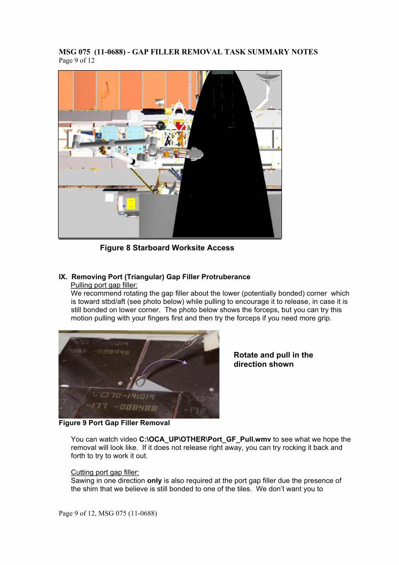
VIII. SSRMS Access and Body Positions
Figure 7 Port Gap Filler SSRMS Position
MSG 075 (11-0688) - GAP FILLER REMOVAL TASK SUMMARY NOTES Page 9 of 12
Page 9 of 12, MSG 075 (11-0688)
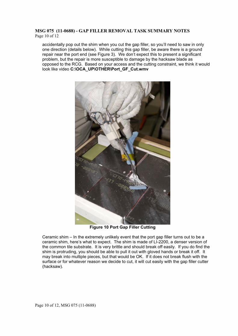
IX. Removing Port (Triangular) Gap Filler Protruberance Pulling port gap filler:
We recommend rotating the gap filler about the lower (potentially bonded) corner which is toward stbd/aft (see photo below) while pulling to encourage it to release, in case it is still bonded on lower corner. The photo below shows the forceps, but you can try this motion pulling with your fingers first and then try the forceps if you need more grip.
Figure 9 Port Gap Filler Removal
You can watch video C:\OCA_UP\OTHER\Port_GF_Pull.wmv to see what we hope the removal will look like. If it does not release right away, you can try rocking it back and forth to try to work it out. Cutting port gap filler: Sawing in one direction only is also required at the port gap filler due the presence of the shim that we believe is still bonded to one of the tiles. We don’t want you to
Rotate and pull in the direction shown
Figure 8 Starboard Worksite Access
MSG 075 (11-0688) - GAP FILLER REMOVAL TASK SUMMARY NOTES Page 10 of 12
Page 10 of 12, MSG 075 (11-0688)
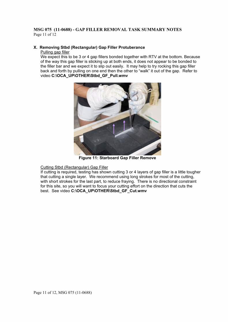
accidentally pop out the shim when you cut the gap filler, so you’ll need to saw in only one direction (details below). While cutting this gap filler, be aware there is a ground repair near the port end (see Figure 3). We don’t expect this to present a significant problem, but the repair is more susceptible to damage by the hacksaw blade as opposed to the RCG. Based on your access and the cutting constraint, we think it would look like video C:\OCA_UP\OTHER\Port_GF_Cut.wmv
Figure 10 Port Gap Filler Cutting
Ceramic shim – In the extremely unlikely event that the port gap filler turns out to be a ceramic shim, here’s what to expect. The shim is made of LI-2200, a denser version of the common tile substrate. It is very brittle and should break off easily. If you do find the shim is protruding, you should be able to pull it out with gloved hands or break it off. It may break into multiple pieces, but that would be OK. If it does not break flush with the surface or for whatever reason we decide to cut, it will cut easily with the gap filler cutter (hacksaw).
MSG 075 (11-0688) - GAP FILLER REMOVAL TASK SUMMARY NOTES Page 11 of 12
Page 11 of 12, MSG 075 (11-0688)
X. Removing Stbd (Rectangular) Gap Filler Protuberance
Pulling gap filler We expect this to be 3 or 4 gap fillers bonded together with RTV at the bottom. Because of the way this gap filler is sticking up at both ends, it does not appear to be bonded to the filler bar and we expect it to slip out easily. It may help to try rocking this gap filler back and forth by pulling on one end then the other to “walk” it out of the gap. Refer to video C:\OCA_UP\OTHER\Stbd_GF_Pull.wmv
Figure 11: Starboard Gap Filler Remove
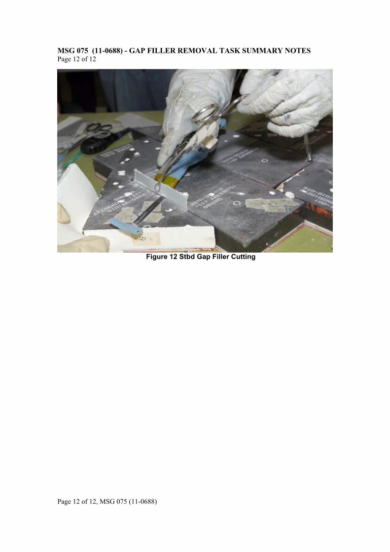
Cutting Stbd (Rectangular) Gap Filler If cutting is required, testing has shown cutting 3 or 4 layers of gap filler is a little tougher that cutting a single layer. We recommend using long strokes for most of the cutting, with short strokes for the last part, to reduce fraying. There is no directional constraint for this site, so you will want to focus your cutting effort on the direction that cuts the best. See video C:\OCA_UP\OTHER\Stbd_GF_Cut.wmv
MSG 075 (11-0688) - GAP FILLER REMOVAL TASK SUMMARY NOTES Page 12 of 12
Page 12 of 12, MSG 075 (11-0688)
Figure 12 Stbd Gap Filler Cutting