Embed Size (px)
Citation preview
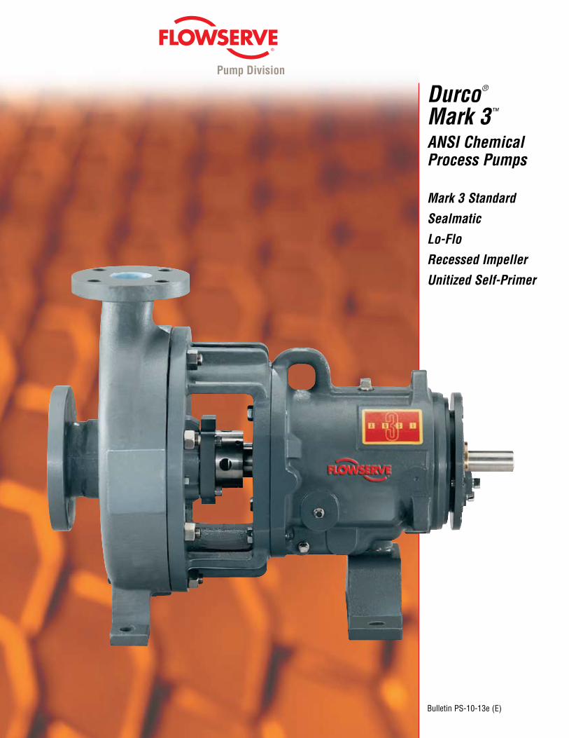
Durco® Mark 3™ ANSI Chemical Process Pumps
Mark 3 Standard
Sealmatic
Lo-Flo
Recessed Impeller
Unitized Self-Primer
Bulletin PS-10-13e (E)
Pump Division
© TriComB2B, 2009, All Rights Reserved.
Pump Division
Pump Supplier To The WorldFlowserve is the
driving force in the global industrial
pump marketplace. No other pump company in the
world has the depth or breadth of
expertise in the successful application of
pre-engineered, engineered and special purpose
pumps and systems.
Pumping SolutionsFlowserve is providing pumping solutions which permit custom-ers to continuously improve productivity, profitability and pumping system reliability.
Market Focused Customer SupportProduct and industry specialists develop effective proposals and solutions directed toward market and customer preferences. They offer technical advice and assistance throughout each stage of the product life cycle, beginning with the inquiry.
Dynamic TechnologiesFlowserve is without peer in the development and application of pump technology, including:•Hydraulicengineering•Mechanicaldesign•Materialsscience• Intelligentpumping•Manufacturingtechnology
Broad Product LinesFlowserve offers a wide range of complementary pump types, from pre-engineered process pumps, to highly engineered and special purpose pumps and systems. Pumps are built to recognized global standards and customer specifications.Pump designs include:
•Singlestageprocess•Betweenbearing single stage•Betweenbearing multistage•Vertical•Submersiblemotor•Rotary•Reciprocating•Nuclear•Specialty
© TriComB2B, 2009, All Rights Reserved.
© TriComB2B, 2009, All Rights Reserved.
Pump Division
3
Table of Contents
Mark 3 Standard Pump ............................4-5 Performance Curves ...... 6
Features and Enhancements Parts Interchangeability ........... 7 PROS+............................ 7 Power Ends .................... 8 Shaft and Bearings Design ............. 9
SealSentry ...............10-11 Impellers .................12-13 ShaftOptions ............... 14 Pump Parts .................. 15 AlloyMaterials.............. 15 Baseplates ...............16-19 Options ....................20-21 Pump Power Monitor ........................ 33
Mark 3 Lo-Flo Pump ........................22-23
Mark 3 SealmaticPump ........................24-25
Mark 3 Self-Priming Pump ........................26-27
Mark 3 Recessed Impeller Pump .........28-29 Complementary Pumps Mark3In-Line.............. 30 Non-MetallicPumps ..... 31 MagneticDrive Pumps .......................... 32 CPXFamilyofISO Pumps .......................... 34
Engineered Services ..... 35
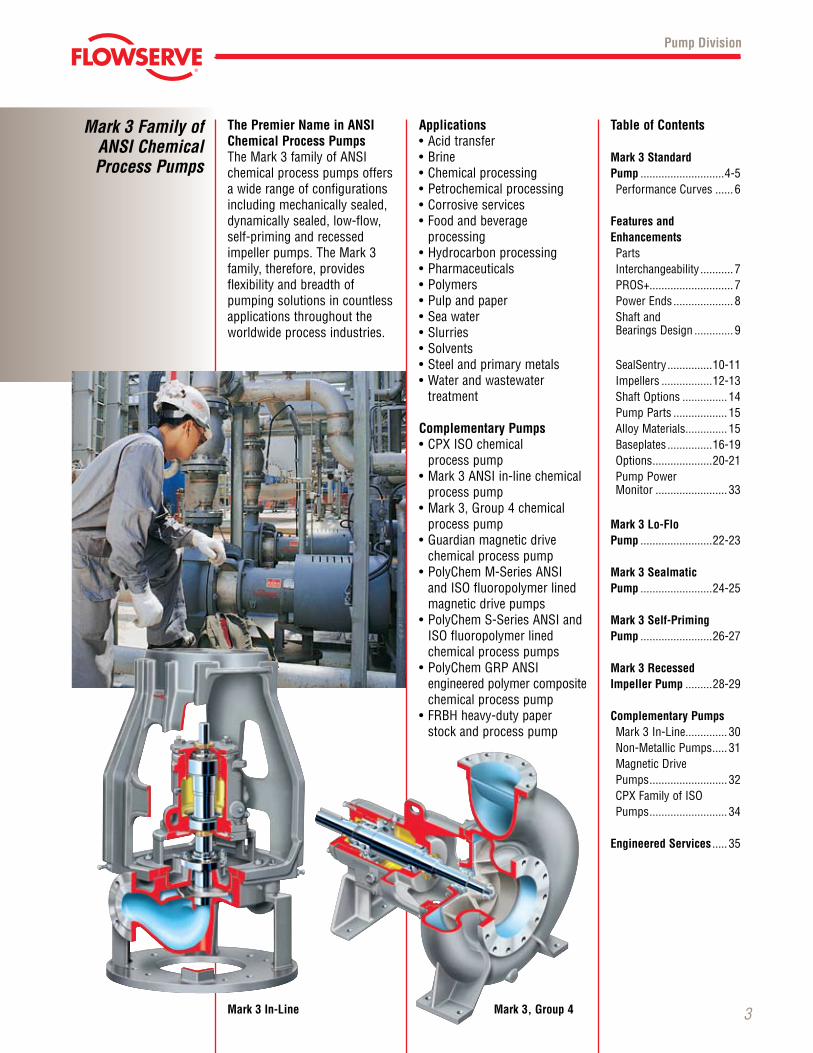
The Premier Name in ANSI Chemical Process PumpsTheMark3familyofANSIchemical process pumps offers a wide range of configurations including mechanically sealed, dynamically sealed, low-flow, self-priming and recessed impellerpumps.TheMark3family, therefore, providesflexibility and breadth of pumping solutions in countless applications throughout the worldwide process industries.
Applications•Acidtransfer•Brine•Chemicalprocessing•Petrochemicalprocessing•Corrosiveservices•Foodandbeverage
processing •Hydrocarbonprocessing•Pharmaceuticals•Polymers•Pulpandpaper•Seawater•Slurries•Solvents•Steelandprimarymetals•Waterandwastewater
treatment
Complementary Pumps •CPXISOchemical
process pump•Mark3ANSIin-linechemical
process pump•Mark3,Group4chemical
process pump•Guardianmagneticdrive
chemical process pump•PolyChemM-SeriesANSI andISOfluoropolymerlined magnetic drive pumps
•PolyChemS-SeriesANSIandISOfluoropolymerlinedchemical process pumps
•PolyChemGRPANSI engineered polymer composite chemical process pump
•FRBHheavy-dutypaper stock and process pump
Mark 3 Family of ANSI Chemical Process Pumps
Mark 3 In-Line Mark 3, Group 4
© TriComB2B, 2009, All Rights Reserved.
Mark 3 Standard ANSI Chemical Process Pump
4
Pump Division
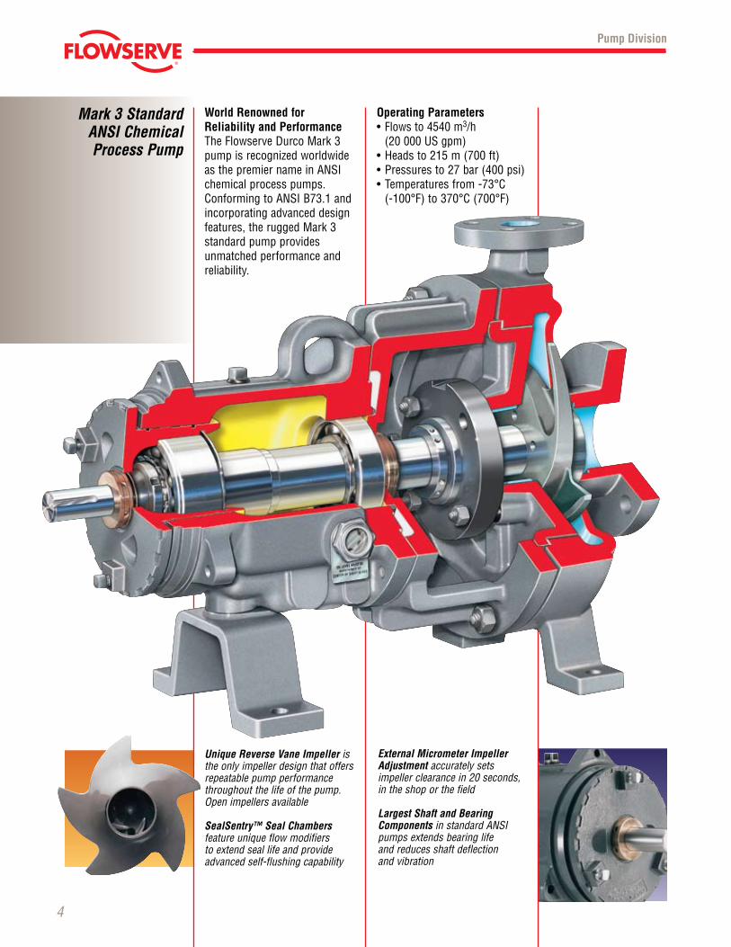
World Renowned for Reliability and PerformanceTheFlowserveDurcoMark3pump is recognized worldwide asthepremiernameinANSIchemical process pumps. ConformingtoANSIB73.1andincorporating advanced design features,theruggedMark3standard pump provides unmatched performance and reliability.
Operating Parameters•Flows to 4540 m3/h
(20 000 US gpm)•Headsto215m(700ft)•Pressuresto27bar(400psi)•Temperaturesfrom-73°C (-100°F)to370°C(700°F)
External Micrometer Impeller Adjustment accurately sets impeller clearance in 20 seconds, in the shop or the field
Largest Shaft and Bearing Components in standard ANSI pumps extends bearing life and reduces shaft deflection and vibration
Unique Reverse Vane Impeller is the only impeller design that offers repeatable pump performance throughout the life of the pump. Open impellers available
SealSentry™ Seal Chambers feature unique flow modifiers to extend seal life and provide advanced self-flushing capability
© TriComB2B, 2009, All Rights Reserved.
5
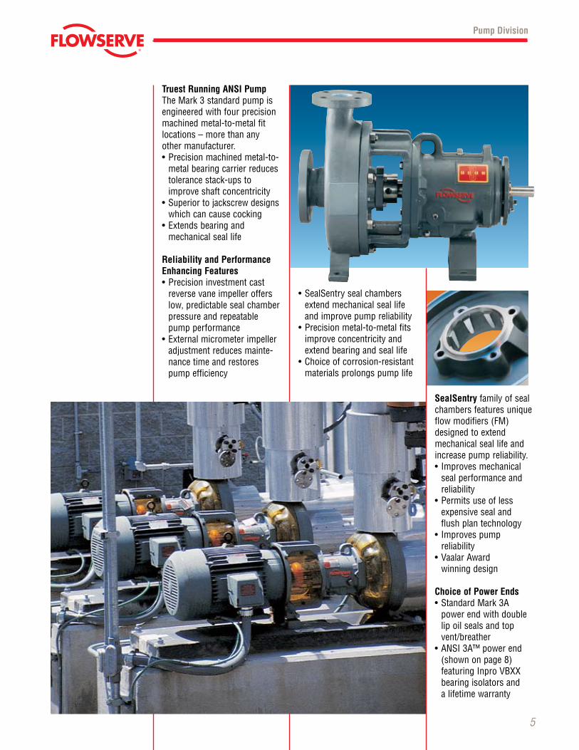
Truest Running ANSI Pump TheMark3standardpumpisengineered with four precision machined metal-to-metal fit locations – more than any other manufacturer.•Precisionmachinedmetal-to-
metal bearing carrier reduces tolerance stack-ups to improve shaft concentricity
•Superior to jackscrew designs which can cause cocking
•Extendsbearingand mechanical seal life
Reliability and Performance Enhancing Features•Precisioninvestmentcast
reverse vane impeller offers low, predictable seal chamber pressure and repeatable pump performance
•Externalmicrometerimpelleradjustment reduces mainte-nance time and restores pump efficiency
•SealSentrysealchambersextend mechanical seal life and improve pump reliability
•Precisionmetal-to-metalfitsimprove concentricity and extend bearing and seal life
•Choiceofcorrosion-resistantmaterials prolongs pump life
Pump Division
SealSentry family of seal chambers features unique flowmodifiers(FM)designed to extend mechanical seal life and increase pump reliability.• Improvesmechanical
seal performance and reliability
•Permitsuseoflessexpensive seal and flush plan technology
• Improvespump reliability•VaalarAward winning design
Choice of Power Ends •StandardMark3A power end with double
lip oil seals and top vent/breather
•ANSI3A™powerend(shown on page 8) featuringInproVBXXbearing isolators and a lifetime warranty
© TriComB2B, 2009, All Rights Reserved.
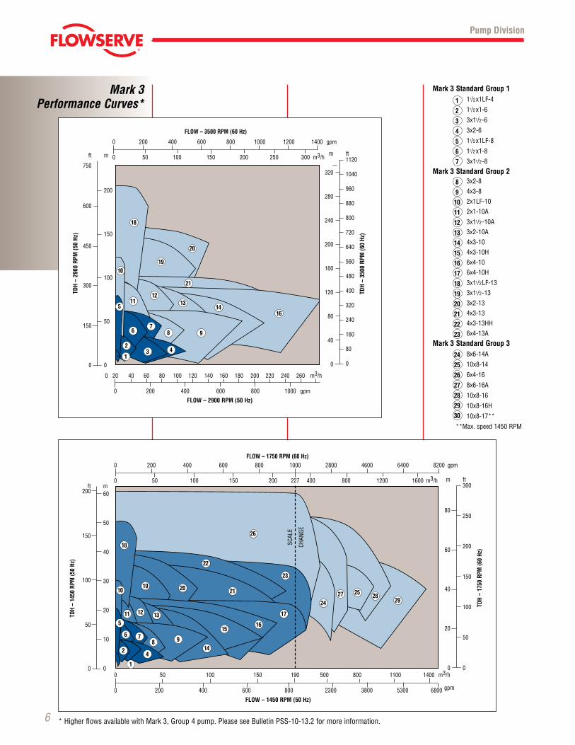
Mark 3Performance Curves*
6
Pump Division
Mark 3 Standard Group 1 11/2x1LF-4
11/2x1-6
3x11/2-6
3x2-6
11/2x1LF-8
11/2x1-8
3x11/2-8
Mark 3 Standard Group 2 3x2-8
4x3-8
2x1LF-10
2x1-10A
3x11/2-10A
3x2-10A
4x3-10
4x3-10H
6x4-10
6x4-10H
3x11/2LF-13
3x11/2-13
3x2-13
4x3-13
4x3-13HH
6x4-13A
Mark 3 Standard Group 3 8x6-14A
10x8-14
6x4-16
8x6-16A
10x8-16
10x8-16H
10x8-17**
**Max.speed1450RPM
1
2
3
4
5
6
7
8
9
10
11
12
13
14
15
16
17
18
19
20
21
22
23
24
25
26
27
28
29
30
*HigherflowsavailablewithMark3,Group4pump.PleaseseeBulletinPSS-10-13.2formoreinformation.
0 20 40 60 80 100 120 140 160 180 200 220 240 260 m3/h
0 200 400 600 800 1000 gpm
ft
750
600
450
300
150
0
m
200
150
100
50
0
TDH
– 29
00 R
PM (5
0 Hz
)
0 200 400 600 800 1000 1200 1400 gpm
0 50 100 150 200 250 300 m3/h
1
23 4
987
6
5
10
1112
1314
16
21
19
20
18
m
320
280
240
200
160
120
80
40
0
ft1120
1040
960
880
800
720
640
560
480
400
320
240
160
80
0TD
H –
3500
RPM
(60
Hz)
FLOW – 3500 RPM (60 Hz)
FLOW – 2900 RPM (50 Hz)
m
80
60
40
20
0
ft300
250
200
150
100
50
0
TDH
– 17
50 R
PM (6
0 Hz
)
ft200
150
100
50
0
m60
50
40
30
20
10
0
TDH
– 14
50 R
PM (5
0 Hz
)
0 200 400 600 800 1000 2800 4600 6400 8200 gpm
0 50 100 150 200 227 400 800 1200 1600 m3/h
FLOW – 1750 RPM (60 Hz)
0 50 100 150 190 500 800 1100 1400 m3/h
0 200 400 600 800 2300 3800 5300 6800 gpm
FLOW – 1450 RPM (50 Hz)
SCAL
E
CHAN
GE
1
2 4
9876
5
10
11 12 13
14
1516
17
21
22
23
26
19 20
18
2427 25 28
29
0 20 40 60 80 100 120 140 160 180 200 220 240 260 m3/h
0 200 400 600 800 1000 gpm
ft
750
600
450
300
150
0
m
200
150
100
50
0
TDH
– 29
00 R
PM (5
0 Hz
)
0 200 400 600 800 1000 1200 1400 gpm
0 50 100 150 200 250 300 m3/h
1
23 4
987
6
5
10
1112
1314
16
21
19
20
18
m
320
280
240
200
160
120
80
40
0
ft1120
1040
960
880
800
720
640
560
480
400
320
240
160
80
0
TDH
– 35
00 R
PM (6
0 Hz
)
FLOW – 3500 RPM (60 Hz)
FLOW – 2900 RPM (50 Hz)
m
80
60
40
20
0
ft300
250
200
150
100
50
0
TDH
– 17
50 R
PM (6
0 Hz
)ft
200
150
100
50
0
m60
50
40
30
20
10
0
TDH
– 14
50 R
PM (5
0 Hz
)
0 200 400 600 800 1000 2800 4600 6400 8200 gpm
0 50 100 150 200 227 400 800 1200 1600 m3/h
FLOW – 1750 RPM (60 Hz)
0 50 100 150 190 500 800 1100 1400 m3/h
0 200 400 600 800 2300 3800 5300 6800 gpm
FLOW – 1450 RPM (50 Hz)
SCAL
E
CHAN
GE
1
2 4
9876
5
10
11 12 13
14
1516
17
21
22
23
26
19 20
18
2427 25 28
29
© TriComB2B, 2009, All Rights Reserved.
7
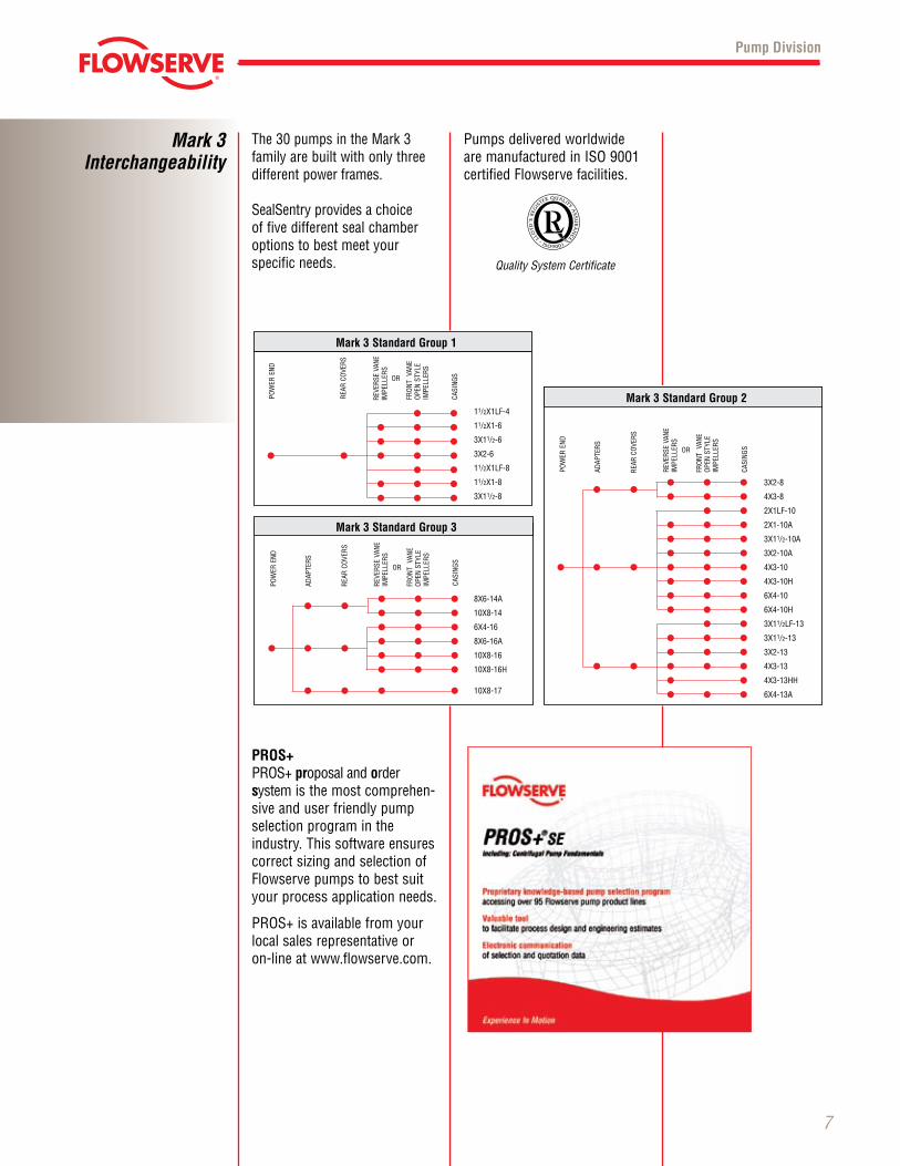
The30pumpsintheMark3 family are built with only three differ ent power frames.
SealSentry pro vides a choice of five different seal chamber options to best meet yourspecific needs.
Pump Division
Mark 3Interchangeability
PROS+PROS+proposal and order system is the most comprehen-sive and user friendly pump selection program in the industry. This software ensures correct sizing and selection of Flowserve pumps to best suit your process application needs.
PROS+isavailablefromyourlocal sales representative or on-line at www.flowserve.com.
Quality System Certificate
MARK III Standard Group II
• • •• • • • •• •• • •• • •• • •• • • • • •• • •• • •• • •• •• • •• • •• • • • •• •• • •
POWEREND
REARCOVERS
ADAPTERS
REVERSEVANE
IMPELLERS
FRONT
VANE
OPENSTYLE
IMPELLERS
CASINGS
3X2-8
4X3-8
2X1LF-10
2X1-10A
3X11/2-10A
3X2-10A
4X3-10
4X3-10H
6X4-10
6X4-10H
3X11/2LF-13
3X11/2-13
3X2-13
4X3-13
4X3-13HH
6X4-13A
OR
Mark 3 Standard Group 2
• •• • •• • •• • • • •• •• • •• • •
POWEREND
REARCOVERS
REVERSEVANE
IMPELLERS
FRONTVANE
OPENSTYLE
IMPELLERS
CASINGS
11/2X1LF-4
11/2X1-6
3X11/2-6
3X2-6
11/2X1LF-8
11/2X1-8
3X11/2-8
OR
POWEREND
REARCOVERS
ADAPTERS
REVERSEVANE
IMPELLERS
FRONTVANE
OPENSTYLE
IMPELLERS
CASINGS
8X6-14A
10X8-14
6X4-16
8X6-16A
10X8-16
10X8-16H
10X8-17
OR
• • •• • • • •• • •• • •• • • • • •• • •• • • •
Mark 3 Standard Group 3
Mark 3 Standard Group 1
Pumps delivered worldwide aremanufacturedinISO9001certified Flowserve facilities.
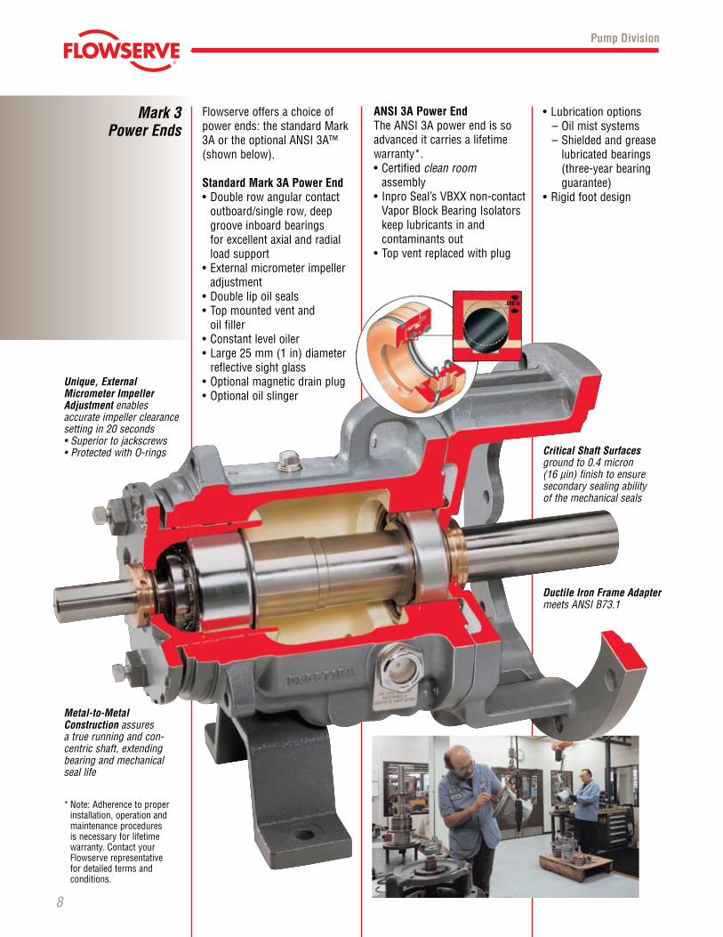
Flowserve offers a choice of powerends:thestandardMark3AortheoptionalANSI3A™(shown below).
Standard Mark 3A Power End•Doublerowangularcontact
outboard/single row, deep groove inboard bearings for excellent axial and radial load support
•Externalmicrometerimpelleradjustment
•Doublelipoilseals•Topmountedventand oil filler•Constantleveloiler•Large25mm(1in)diameter
reflective sight glass•Optionalmagneticdrainplug•Optionaloilslinger
Mark 3 Power Ends
8
ANSI 3A Power EndTheANSI3Apowerendissoadvanced it carries a lifetime warranty*.•Certifiedclean room
assembly• InproSeal’sVBXXnon-contactVaporBlockBearingIsolatorskeep lubricants in and
contaminants out•Topventreplacedwithplug
Unique, External Micrometer Impeller Adjustment enables accurate impeller clearance setting in 20 seconds•Superiortojackscrews•ProtectedwithO-rings
Metal-to-Metal Construction assures a true running and con- centric shaft, extending bearing and mechanicalseal life
*Note:Adherencetoproperinstallation, operation and maintenance procedures is necessary for lifetime warranty. Contact your Flowserve representative for detailed terms and conditions.
•Lubricationoptions–Oilmistsystems– Shielded and grease
lubricated bearings (three-year bearing guarantee)
•Rigidfootdesign
Critical Shaft Surfaces ground to 0.4 micron (16 µin) finish to ensure secondary sealing ability of the mechanical seals
Ductile Iron Frame Adapter meets ANSI B73.1
Pump Division
© TriComB2B, 2009, All Rights Reserved.
.010 in
© TriComB2B, 2009, All Rights Reserved.
9
The Heart of the Pump: Shaft and Bearing DesignFlowserve offers the largest shaft and bearing com po nents availableinstandardANSIpumps. The follow ing comparisonofaMark3 Group2powerendwith that of a major competitor demonstrates the benefits of heavy-duty design.
Pump Division
Mark 3Heavy-Duty
Shaft and Bearings
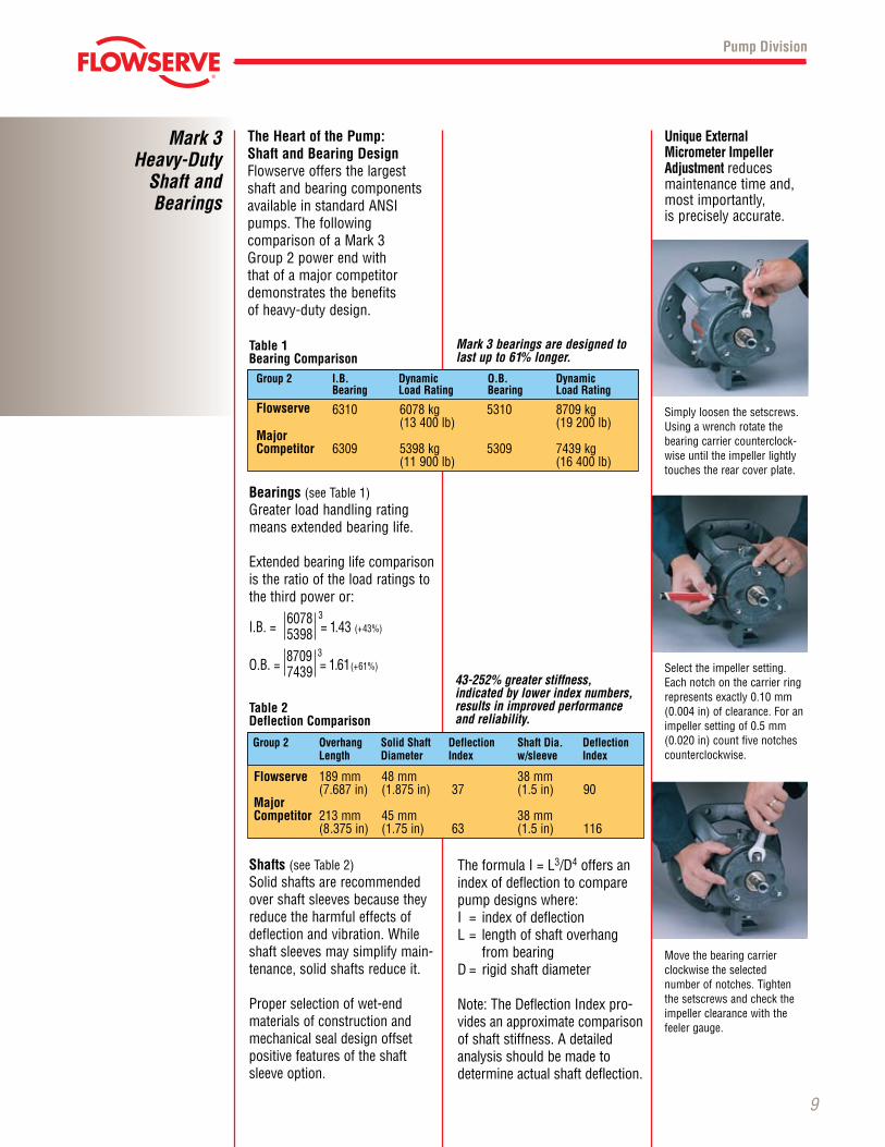
Unique External Micrometer Impeller Adjustment reduces maintenance time and, most impor tantly, is precisely accurate.
Simply loosen the setscrews. Using a wrench rotate the bear ing carrier counter clock-wise until the impeller lightly touches the rear cover plate.
Select the impeller setting. Each notch on the carrier ring represents exactly 0.10 mm (0.004 in) of clearance. For an impeller setting of 0.5 mm(0.020 in) count five notches counterclockwise.
Movethebearingcarrier clock wise the selected number of notches. Tighten the setscrews and check the impeller clearance with the feeler gauge.
Bearings (see Table 1)Greaterloadhandlingratingmeans extended bearing life.
Extended bearing life comparison is the ratio of the load ratings to the third power or:
I.B.= 6078 3= 1.43 (+43%) 5398
O.B.= 8709 3= 1.61(+61%) 7439
Shafts (see Table 2)Solid shafts are recom mend ed over shaft sleeves because they reduce the harmful effects of deflectionandvibration.Whileshaft sleeves may simplify main-tenance, solid shafts reduce it.
Proper selection of wet-end materials of con struc tion and mechan ical seal design offset posi tive features of the shaft sleeve option.
Table 1Bearing Comparison
Mark 3 bearings are designed to last up to 61% longer.
Flowserve 189 mm 48 mm 38 mm (7.687 in) (1.875 in) 37 (1.5 in) 90 Major Competitor 213 mm 45 mm 38 mm (8.375 in) (1.75 in) 63 (1.5 in) 116
Table 2Deflection Comparison
43-252% greater stiffness, indicated by lower index numbers, results in improved performance and reliability.
Group 2 Overhang Solid Shaft Deflection Shaft Dia. Deflection Length Diameter Index w/sleeve Index
TheformulaI=L3/D4 offers an index of deflection to compare pump designs where:I = indexofdeflectionL= lengthofshaftoverhang
from bearingD= rigidshaftdiameter
Note:TheDeflectionIndexpro-vides an approxi mate compari son of shaft stiff ness. A detailed analysis should be made to deter mine actual shaft deflection.
Flowserve 6310 6078 kg 5310 8709 kg (13 400 lb) (19 200 lb) Major Competitor 6309 5398 kg 5309 7439 kg (11 900 lb) (16 400 lb)
Group 2 I.B. Dynamic O.B. Dynamic Bearing Load Rating Bearing Load Rating
© TriComB2B, 2009, All Rights Reserved.
Advanced Mark 3 SealSentry Design TechnologySealSentry chambers maximize seal life, reduce pump operat-ing costs and improve pump reliability.•Extendseallife
– Self-flushing– Self-venting– Self-draining
•Reducemaintenanceandrepair costs
•Permituseoflessexpensiveseals and flush plans– Flush plans 11, 32, 52, 53,
etc. can be eliminated• Increasemechanicalseallife•Provideasaferenvironment
for personnel
Mark 3 SealSentry Chambers
10
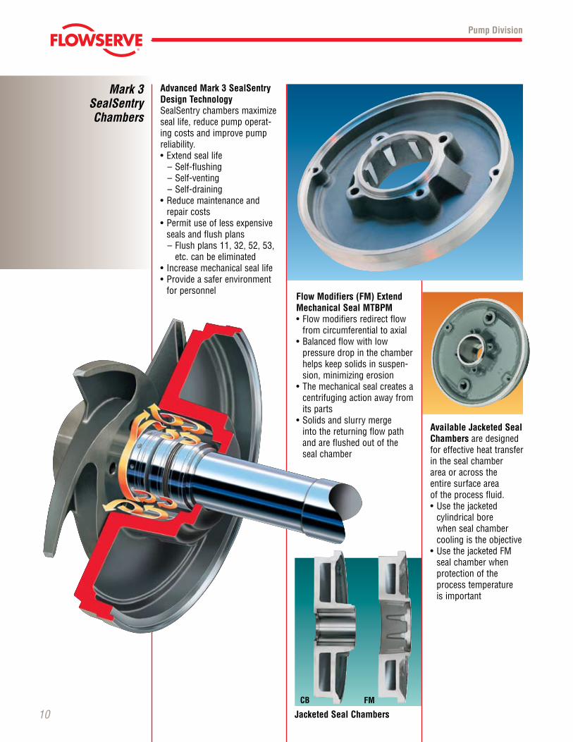
Flow Modifiers (FM) Extend Mechanical Seal MTBPM•Flowmodifiersredirectflow
from circumferential to axial •Balancedflowwithlow
pressure drop in the chamber helps keep solids in suspen-sion, minimizing erosion
•Themechanicalsealcreatesacentrifuging action away from its parts
•Solidsandslurrymerge into the returning flow path and are flushed out of the seal chamber
Available Jacketed Seal Chambers are designed for effective heat transfer in the seal chamber area or across the entire surface areaof the process fluid.•Usethejacketed
cylindrical bore when seal chamber cooling is the objective
•UsethejacketedFMseal chamber when protection of the process temperature is important
Pump Division
FMCB
Jacketed Seal Chambers
© TriComB2B, 2009, All Rights Reserved.
11
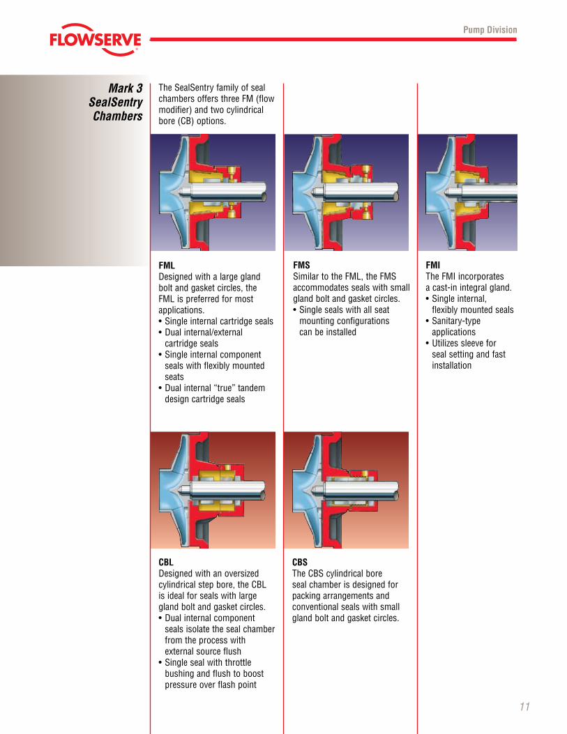
The SealSentry family of seal chambersoffersthreeFM(flowmodifier) and two cylindrical bore (CB) options.
FMLDesigned with a large gland bolt and gasket circles, the FMLispreferredformostapplications.•Singleinternalcartridgeseals•Dualinternal/external
cartridge seals•Singleinternalcomponent
seals with flexibly mounted seats
•Dualinternal“true”tandemdesign cartridge seals
FMSSimilartotheFML,theFMSaccommodates seals with small gland bolt and gasket circles.•Singlesealswithallseat
mounting configurations can be installed
FMITheFMIincorporates a cast-in integral gland.•Singleinternal,
flexibly mounted seals•Sanitary-type
applications•Utilizessleevefor
seal setting and fast installation
Pump Division
Mark 3 SealSentry Chambers
CBLDesigned with an oversized cylindricalstepbore,theCBL is ideal for seals with large gland bolt and gasket circles.•Dualinternalcomponent
seals isolate the seal chamber from the process with external source flush
•Singlesealwiththrottle bushing and flush to boost pressure over flash point
CBSThe CBS cylindrical bore seal chamber is designed for packing arrangements and conventional seals with small gland bolt and gasket circles.
© TriComB2B, 2009, All Rights Reserved.
Mark 3Impellers
12
Pump Division
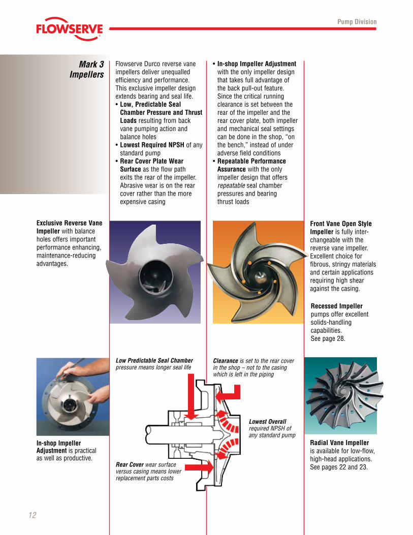
Radial Vane Impeller is available for low-flow, high-head applications. See pages 22 and 23.
Exclusive Reverse Vane Impeller with balance holes offers important performance enhancing, mainte nance-reducing advantages.
Front Vane Open Style Impeller is fully inter-changeable with the reverse vane impeller. Excellent choice for fibrous, stringy materials and certain applications requiring high shear against the casing.
In-shop Impeller Adjustment is practical as well as productive.
Flowserve Durco reverse vane impellers deliver unequalled efficiency and perfor mance. This exclu sive impeller design ex tends bearing and seal life.•Low, Predictable Seal
Chamber Pressure and Thrust Loads resulting from back vane pump ing action and balance holes
•Lowest Required NPSH of any standard pump
•Rear Cover Plate Wear Surface as the flow path exits the rear of the impeller. Abra sive wear is on the rear cover rather than the more expensive casing
Recessed Impeller pumps offer excellent solids-handling capa bilities. See page 28.
• In-shop Impeller Adjust ment with the only impeller design that takes full advan tage of the back pull-out feature. Since the criti cal running clear ance is set between the rear of the impel ler and the rear cover plate, both impeller and mechan ical seal set tings canbedoneintheshop,“onthebench,”insteadofunderadverse field conditions
•Repeatable Perfor mance Assurance with the only impeller design that offers repeatable seal chamber
pres sures and bearing thrust loads
Low Predictable Seal Chamber pressure means longer seal life
Rear Cover wear surfaceversus casing means lower replacement parts costs
Clearance is set to the rear cover in the shop – not to the casing which is left in the piping
Lowest Overall requiredNPSHof any standard pump
© TriComB2B, 2009, All Rights Reserved.
13
Pump Division
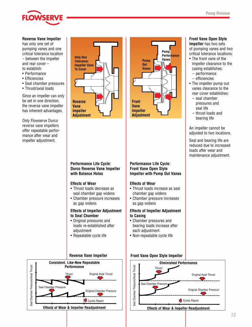
Performance Life Cycle:Durco Reverse Vane Impeller with Balance Holes Effects of Wear•Thrustloadsdecreaseas
seal chamber gap widens•Chamberpressureincreases
as gap widens
Effects of Impeller Adjustment to Seal Chamber•Originalpressuresand
loads re-established after adjustment
•Repeatablecyclelife
Performance Life Cycle:Front Vane Open Style Impeller with Pump Out Vanes Effects of Wear•Thrustloadsincreaseasseal
chamber gap widens•Chamberpressureincreases
as gap widens
Effects of Impeller Adjustment to Casing•Chamberpressuresand
bearing loads increase after each adjust ment
•Non-repeatablecyclelife
Reverse Vane Impeller has only one set of pumping vanes and one critical toler ance location – between the impeller and rear cover – to establish:•Performance•Efficiencies•Sealchamberpressures•Thrust/axialloads
Since an impeller can only be set in one direction, the reverse vane impeller has inherent advantages.
OnlyFlowserveDurcoreverse vane impellers offer repeatable perfor-mance after wear and impeller adjustment.
Front Vane Open Style Impeller has two sets of pumping vanes and two critical tolerance locations:•Thefrontvaneofthe
impeller clearance to the casing establishes:– performance – efficiencies
•Theimpellerpumpoutvanes clearance to the rear cover establishes:– seal chamber
pressures and seal life
– thrust loads and bearing life
An impeller cannot be adjusted to two locations.
Seal and bearing life are reduced due to increased loads after wear and maintenance adjustment.
ReverseVaneImpellerAdjustment
FrontVaneImpellerAdjustment
Only One Tolerance: Impeller Vane To Cover
Pump- Out Vanes
Pump Performance Vanes
Seal
Cha
mbe
r Pr
essu
re/A
xial
Thr
ust
Seal
Cha
mbe
r Pr
essu
re/A
xial
Thr
ust
Reverse Vane Impeller Front Vane Open Style Impeller
Consistent, Like-New RepeatablePerformance
Thrust OriginalAxialThrust
Seal Chamber Pressure OriginalChamberPressure
CyclesRepart
Effects of Wear & Impeller Readjustment
Diminished Performance Thrust
OriginalAxialThrust
Seal Chamber Pressure
OriginalChamberPressure
CyclesRepart
Effects of Wear & Impeller Readjustment
© TriComB2B, 2009, All Rights Reserved.
Mark 3Shafts and
Sleeves
14
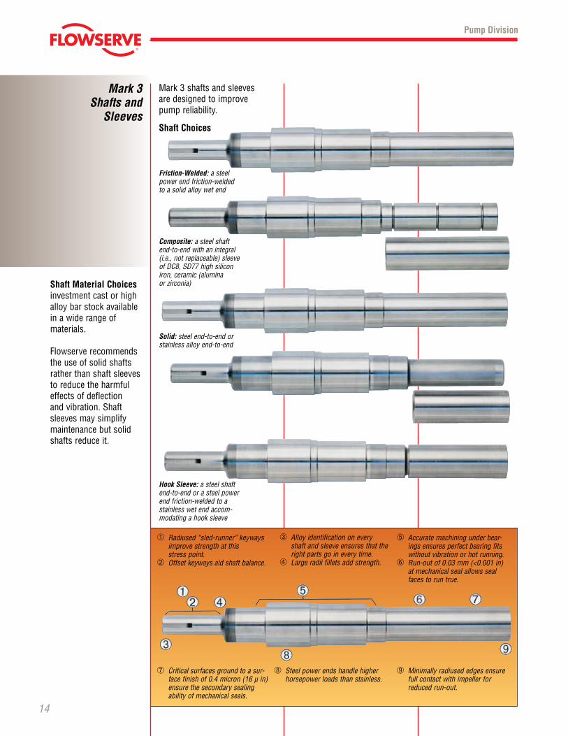
Shaft Material Choices investment cast or high alloy bar stock available in a wide range of materi als.
Flowserve recommends the use of solid shafts rather than shaft sleeves to reduce the harmful effects of deflec tion and vibra tion. Shaft sleeves may simplify main te nance but solid shafts reduce it.
Pump Division
Shaft Choices
Friction-Welded: a steel power end fric tion-welded to a solid alloy wet end
Composite: a steel shaft end-to-end with an inte gral (i.e., not replaceable) sleeve of DC8, SD77 high silicon iron, ceramic (alumina or zirconia)
Solid: steel end-to-end or stainless alloy end-to-end
Hook Sleeve: a steel shaft end-to-end or a steel power end friction-welded to a stain less wet end accom-modatingahooksleeve
Mark3shaftsandsleeves are designed to improve pump reliability.
➄ Accurate machining under bear-ings ensures perfect bearing fits without vibration or hot running.
➅ Run-out of 0.03 mm (<0.001 in) at mechanical seal allows seal faces to run true.
➆ Critical surfaces ground to a sur-face finish of 0.4 micron (16 µ in) ensure the secondary sealing ability of mechanical seals.
➇ Steel power ends handle higher horse power loads than stainless.
➀ Radiused“sled-runner”keywaysimprove strength at this
stress point.➁ Offsetkeywaysaidshaftbalance.
➂ Alloy identification on every shaft and sleeve ensures that the right parts go in every time.
➃ Large radii fillets add strength.
➈ Minimally radiused edges ensure full contact with impeller for reduced run-out.
© TriComB2B, 2009, All Rights Reserved.
15
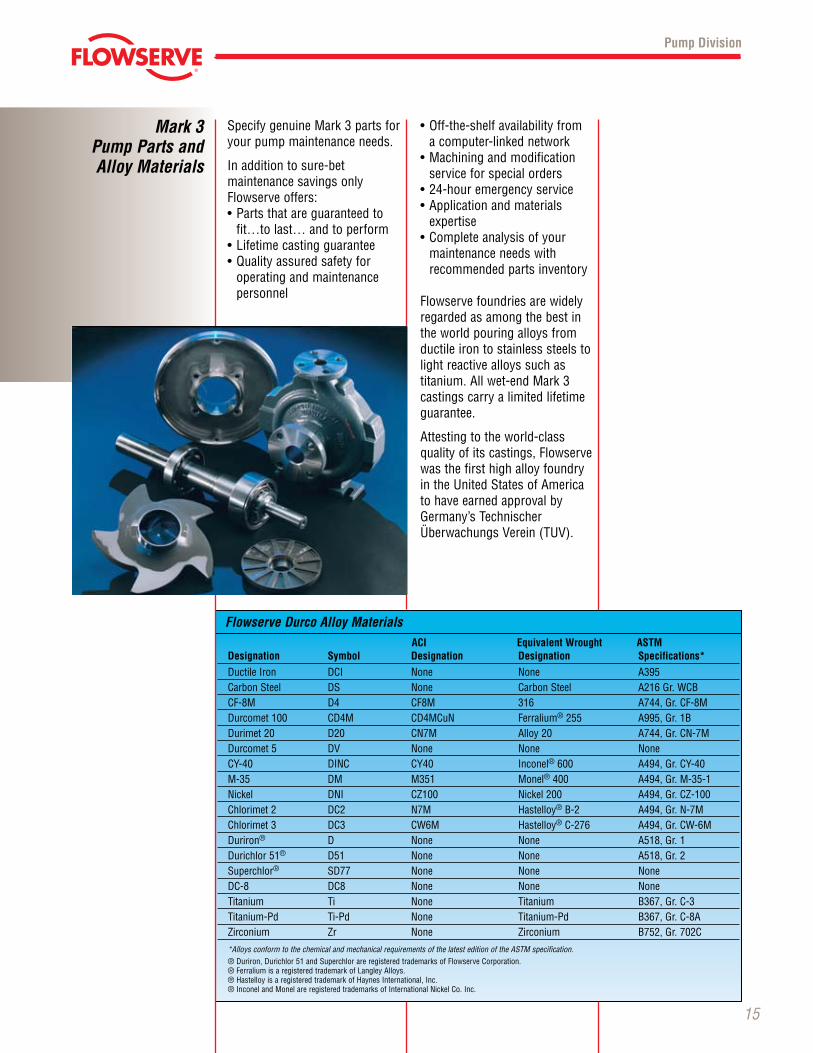
SpecifygenuineMark3partsforyour pump maintenance needs.
Inadditiontosure-bet maintenance sav ings only Flowserve offers:•Partsthatareguaranteedto
fit…to last… and to perform•Lifetimecastingguarantee•Qualityassuredsafetyfor operating and main te nance
personnel
•Off-the-shelfavailabilityfrom a computer-linked network•Machiningandmodification
service for special orders•24-houremergencyservice•Applicationandmaterials
expertise •Completeanalysisofyour
maintenance needs with recom mended parts inventory
Flowserve foundries are widely regarded as among the best in the world pouring alloys from ductile iron to stainless steels to light reactive alloys such as titanium.Allwet-endMark3cast ings carry a limited lifetime guarantee.
Attesting to the world-class quality of its cast ings, Flowserve was the first high alloy foundry in the United States of America to have earned approval by Germany’sTechnischerÜberwachungsVerein(TUV).
Pump Division
ACI Equivalent Wrought ASTM D esignation Symbol Designation Designation Specifications*
DuctileIron DCI None None A395 CarbonSteel DS None CarbonSteel A216Gr.WCB CF-8M D4 CF8M 316 A744,Gr.CF-8M Durcomet100 CD4M CD4MCuN Ferralium®255 A995,Gr.1B Durimet20 D20 CN7M Alloy20 A744,Gr.CN-7M Durcomet5 DV None None None CY-40 DINC CY40 Inconel®600 A494,Gr.CY-40 M-35 DM M351 Monel®400 A494,Gr.M-35-1 Nickel DNI CZ100 Nickel200 A494,Gr.CZ-100 Chlorimet2 DC2 N7M Hastelloy®B-2 A494,Gr.N-7M Chlorimet3 DC3 CW6M Hastelloy®C-276 A494,Gr.CW-6M Duriron® D None None A518,Gr.1 Durichlor 51® D51 None None A518,Gr.2 Superchlor® SD77 None None None DC-8 DC8 None None None Titanium Ti None Titanium B367,Gr.C-3 Titanium-Pd Ti-Pd None Titanium-Pd B367,Gr.C-8A Zirconium Zr None Zirconium B752,Gr.702C
*Alloys conform to the chemical and mechanical requirements of the latest edition of the ASTM specification. ® Duriron, Durichlor 51 and Superchlor are registered trademarks of Flowserve Corporation. ®FerraliumisaregisteredtrademarkofLangleyAlloys. ®HastelloyisaregisteredtrademarkofHaynesInternational,Inc. ®InconelandMonelareregisteredtrademarksofInternationalNickelCo.Inc.
Flowserve Durco Alloy Materials
Mark 3 Pump Parts and Alloy Materials
© TriComB2B, 2009, All Rights Reserved.
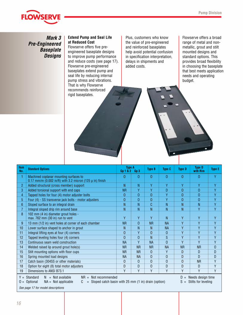
Extend Pump and Seal Life at Reduced Cost Flowserve offers five pre-engineered baseplate designs to improve pump performance and reduce costs (see page 17). Flowserve pre-engineered baseplates extend pump and seal life by reducing internal pump stress and vibrations. That is why Flowserve recommends reinforced rigid baseplates.
Mark 3Pre-Engineered
BaseplateDesigns
16
Plus, customers who know the value of pre-engineered and rein forced base plates help avoid potential con fusion in specifi ca tion inter pre tation, delays in ship ments and added costs.
Flowserve offers a broad range of metal and non-metallic, grout and stilt mounted designs and standard options. This provides broad flexi bility in choos ing the baseplate that best meets appli ca tion needs and operating budget.
Pump Division
1 Machinedcoplanarmountingsurfacesto O O O O O O Y 0.17 mm/m (0.002 in/ft) with 3.2 micron (125 µ in) finish 2 Addedstructural(crossmember)support N N Y Y Y Y Y 3 Addedtorsionalsupportwithendcaps NR Y Y D O O Y 4 Tappedholesforfour(4)motoradjusterbolts O O O Y O O Y 5 Four(4)-SStransversejackbolts-motoradjusters O O O Y O O Y 6 Slopedsurfacetoanintegraldrain N N C N N N Y 7 Integralslopeddriprimaroundbase N N N N N Y Y 8 102 mm (4 in) diameter grout holes - max.762mm(30in)runtovent Y Y Y N Y Y Y 9 13mm(1/2in)ventholesatcornerofeachchamber NR O NR NA Y Y Y 10 Lowersurfaceshapedtoanchoringrout N N N NA Y Y Y 11 Integralliftingeyesatfour(4)corners O Y O O Y Y Y 12 Tappedlevelingholesfour(4)corners O O N S Y Y Y 13 Continuousseamweldconstruction NA Y NA O Y Y Y 14 Weldedraisedliparoundgrouthole(s) NR NR NR NA NR NR O 15 Stiltmountingoptionswithfloorcups NR NR O Y D D D 16 Springmountedloaddesigns NA NA O O D D D 17 Catchbasin(304SSorothermaterials) O O O O O NR Y 18 Optionforeight(8)totalmotoradjusters D D O D D D Y 19 DimensionstoANSIB73.1 Y Y Y Y Y Y Y
Y= Standard N = Notavailable NR = Notrecommended D = NeedsdesigntimeO= Optional NA= Notapplicable C = Slopedcatchbasinwith25mm(1in)drain(option) S = Stiltsforleveling
See page 17 for model descriptions
Item Standard Options Type A Type B Type C Type D Type D Type E No. Gp 1 & 2 Gp 3 with Rim
© TriComB2B, 2009, All Rights Reserved.
17
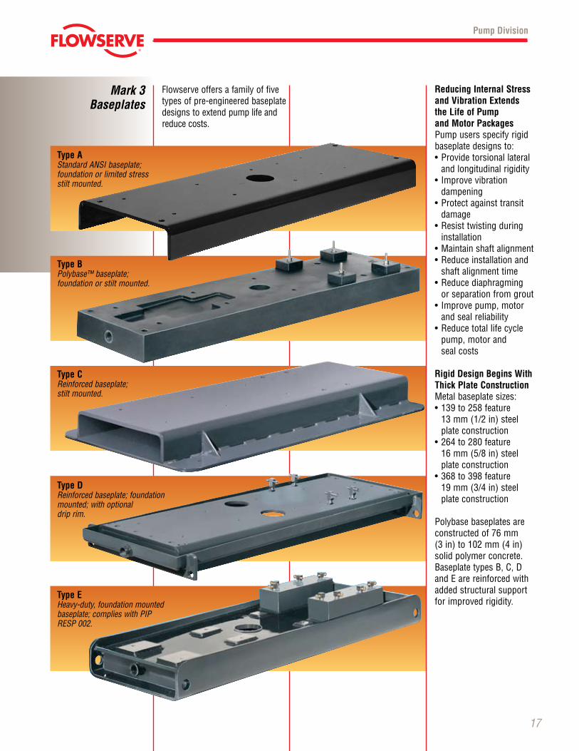
Flowserve offers a family of five types of pre-engineered baseplate designs to extend pump life and reduce costs.
Pump Division
Reducing Internal Stress and Vibration Extends the Life of Pump and Motor PackagesPump users specify rigid baseplate designs to:•Providetorsionallateral
and longitudinal rigidity• Improvevibration dampening•Protectagainsttransit
damage•Resisttwistingduring
installation•Maintainshaftalignment•Reduceinstallationand
shaft alignment time•Reducediaphragming
or separation from grout• Improvepump,motor
and seal reliability•Reducetotallifecycle
pump, motor and seal costs
Rigid Design Begins With Thick Plate ConstructionMetalbaseplatesizes:•139to258feature
13 mm (1/2 in) steel plate construction
•264to280feature 16 mm (5/8 in) steel plate construction
•368to398feature 19 mm (3/4 in) steel plate construction
Polybase baseplates are constructed of 76 mm (3 in) to 102 mm (4 in) solid polymer concrete. Base plate types B, C, D and E are reinforced with added structural support for improved rigidity.
Mark 3Baseplates
Type AStandard ANSI baseplate; founda tion or limited stress stilt mounted.
Type BPolybase™baseplate;foundation or stilt mounted.
Type CRein forced base plate; stilt mounted.
Type DReinforced base plate; foundation mounted; with optional drip rim.
Type EHeavy-duty,foundationmountedbaseplate;complieswithPIPRESP002.
© TriComB2B, 2009, All Rights Reserved.
Polybase™ SolidPolymer Concrete
Baseplate
18
Pump Division
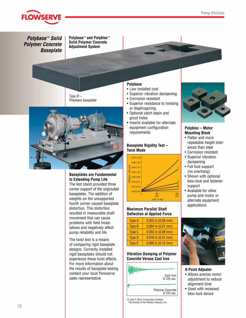
Polybase™ and Polybloc™ Solid Polymer Concrete Adjustment System
Polybloc – MotorMounting Block•Flatterandmore
repeatable height toler-ances than steel
•Corrosionresistant•Superiorvibration
dampening•Fullfootsupport
(no overhang)•Shownwithoptional
bloc-lock and fastener support
•Availableforotherpump and motor or alternate equipment applications
8-Point Adjuster•Allowsprecisemotor
adjustment to reduce alignment time
•Usedwithrecessedbloc-lock device
Baseplates are Fundamental to Extending Pump LifeThe test stand provided three corner support of the ungrouted base plates. The addition of weights on the unsupported fourth corner caused baseplate distor tion. This distortion resulted in measurable shaft move ment that can cause problems with field instal-lations and nega tively affect pump reliability and life.
The twist test is a means of comparing rigid base plate designs. Correct ly installed rigid baseplates should not experience these twist effects. For more infor ma tion about the results of base plate test ing contact your local Flowserve sales representative.
Type B – Polybasebaseplate
Polybase•Lowinstalledcost•Superiorvibrationdampening•Corrosionresistant•Superiorresistancetotwisting
or diaphragming•Optionalcatchbasinand grout holes• Insertsavailableforalternate
equip ment con figuration requirements
CastIron0.125 sec.
Polymer Concrete0.125 sec.
©JohnF.Kane,CompositesInstitute,TheSocietyofthePlasticsIndustry,Inc.
Baseplate Rigidity Test – Twist Mode
0.070 (1.78)
0.060 (1.52)
0.050 (1.27)
0.040 (1.02)
0.030 (0.08)
0.020 (0.51)
0.010 (0.25)
0.000 (0.00)
A
D
E
BC
0 100 200 (45) (91)
Load-lb(kg)
Defle
ctio
n –
inch
(mm
)
Type A 0.022 in (0.56 mm)
Type B 0.004 in (0.01 mm)
Type C 0.003 in (0.08 mm)
Type D 0.016 in (0.41 mm)
Type E 0.005 in (0.13 mm)
Maximum Parallel Shaft Deflection at Applied Force
Vibration Damping of Polymer Concrete Versus Cast Iron
© TriComB2B, 2009, All Rights Reserved.
19
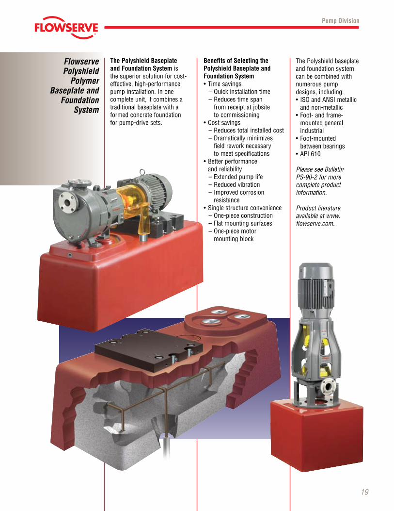
The Polyshield Baseplate and Foundation System is the superior solution for cost- effective, high-performance pumpinstallation.Inone complete unit, it combines a traditional baseplate with a formed concrete foundation for pump-drive sets.
Benefits of Selecting the Polyshield Baseplate and Foundation System•Timesavings–Quickinstallationtime–Reducestimespan
from receipt at jobsite to commissioning
•Costsavings–Reducestotalinstalledcost– Dramatically minimizes
field rework necessary to meet specifications
•Betterperformance and reliability– Extended pump life–Reducedvibration–Improvedcorrosion
resistance•Singlestructureconvenience–One-piececonstruction– Flat mounting surfaces–One-piecemotor
mounting block
The Polyshield baseplate and foundation system can be combined with numerous pump designs, including:• ISOandANSImetallic
and non-metallic•Foot-andframe-
mounted general industrial
•Foot-mounted between bearings
•API610
PleaseseeBulletin PS-90-2formore complete product information.
Productliterature available at www.flowserve.com.
Pump Division
Flowserve Polyshield
Polymer Baseplate and
Foundation System
© TriComB2B, 2009, All Rights Reserved.
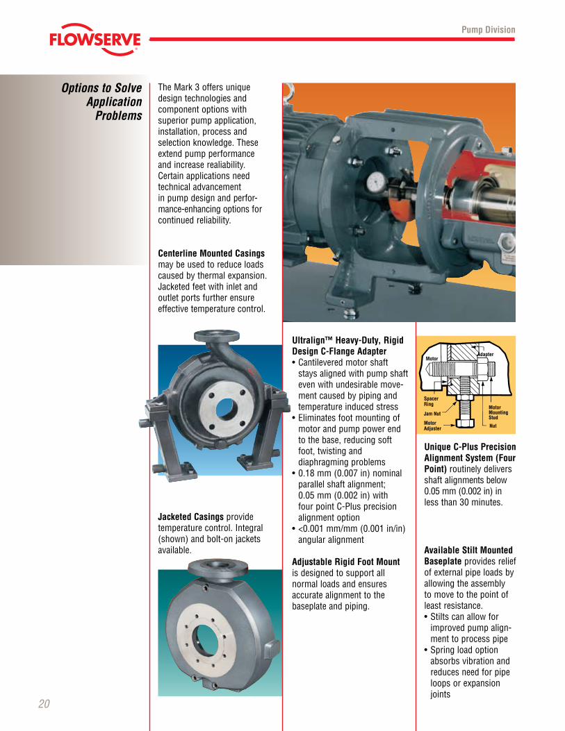
TheMark3offersuniquedesign technologies and component options with superior pump application, installation, process and selection knowledge. These extend pump performance and increase realiability.Certain applications need technical advancement in pump design and perfor-mance-enhancing options for continued reliability.
Centerline Mounted Casings may be used to reduce loads caused by thermal expansion. Jacketed feet with inlet and outlet ports further ensure effective temperature control.
Options to Solve Application
Problems
20
Ultralign™ Heavy-Duty, Rigid Design C-Flange Adapter •Cantileveredmotorshaft
stays aligned with pump shaft even with undesirable move-ment caused by piping and temperature induced stress
•Eliminatesfootmountingofmotor and pump power end to the base, reducing soft foot, twisting and diaphragming problems
•0.18mm(0.007in)nominalparallel shaft alignment; 0.05 mm (0.002 in) with four point C-Plus precision alignment option
•<0.001mm/mm(0.001in/in)angular alignment
Adjustable Rigid Foot Mountis designed to support allnormal loads and ensures accurate alignment to the baseplate and piping.
Unique C-Plus Precision Alignment System (Four Point) routinely delivers shaft alignments below 0.05 mm (0.002 in) in less than 30 minutes.
Available Stilt Mounted Baseplate provides relief of external pipe loads by allowing the assembly to move to the point of least resistance.•Stiltscanallowfor
improved pump align-ment to process pipe
•Springloadoptionabsorbs vibration and reduces need for pipe loops or expansion joints
Pump Division
Jacketed Casings provide temperaturecontrol.Integral(shown) and bolt-on jackets available.
MotorAdapter
Motor Mounting Stud
Nut
Spacer Ring
Jam Nut
Motor Adjuster
© TriComB2B, 2009, All Rights Reserved.
21
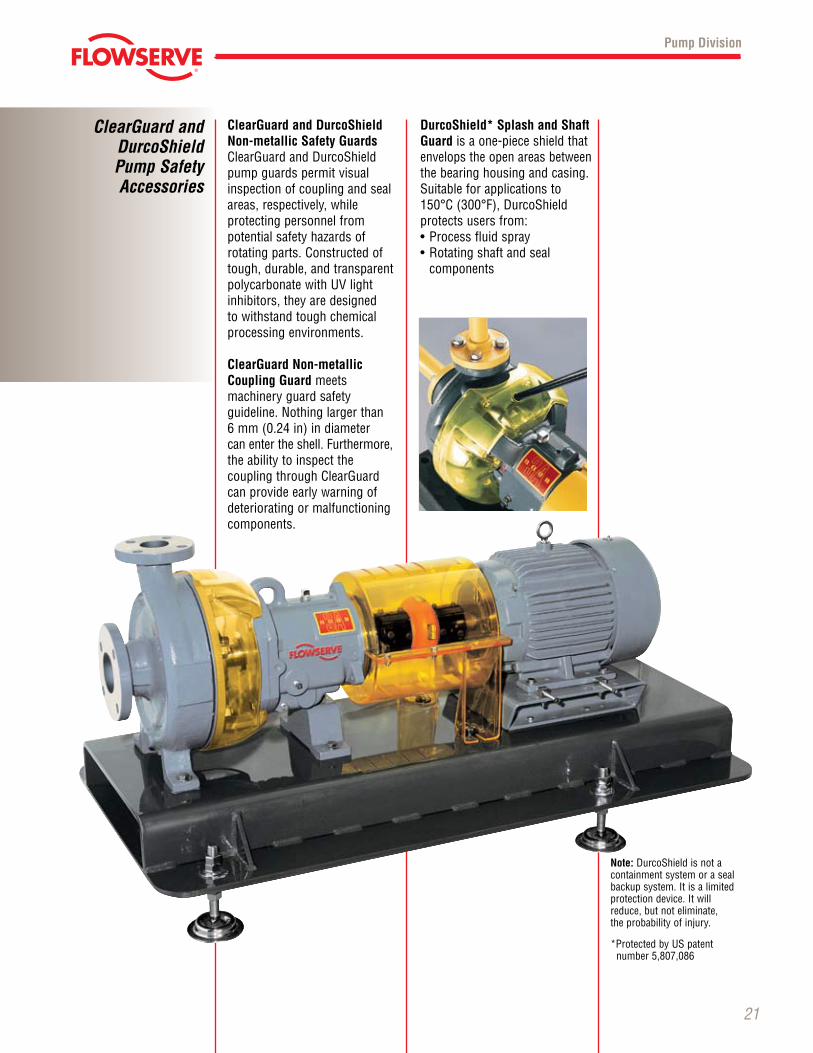
ClearGuard and DurcoShield Non-metallic Safety GuardsClearGuardandDurcoShieldpump guards permit visual inspection of coupling and seal areas, respectively, while protecting personnel from potential safety hazards of rotating parts. Constructed of tough, durable, and transparent polycarbonatewithUVlightinhibitors, they are designed to withstand tough chemical processing environments.
ClearGuard Non-metallic Coupling Guard meets machinery guard safety guideline.Nothinglargerthan 6 mm (0.24 in) in diameter can enter the shell. Furthermore, the ability to inspect the couplingthroughClearGuardcan provide early warning of deteriorating or malfunctioning components.
DurcoShield* Splash and Shaft Guard is a one-piece shield that envelops the open areas between the bearing housing and casing. Suitable for applications to 150°C(300°F),DurcoShield protects users from:•Processfluidspray•Rotatingshaftandseal
components
Note: DurcoShield is not a containment system or a seal backupsystem.Itisalimitedprotectiondevice.Itwillreduce, but not eliminate, the probability of injury.
*Protected by US patent number 5,807,086
Pump Division
ClearGuard and DurcoShield Pump Safety Accessories
© TriComB2B, 2009, All Rights Reserved.
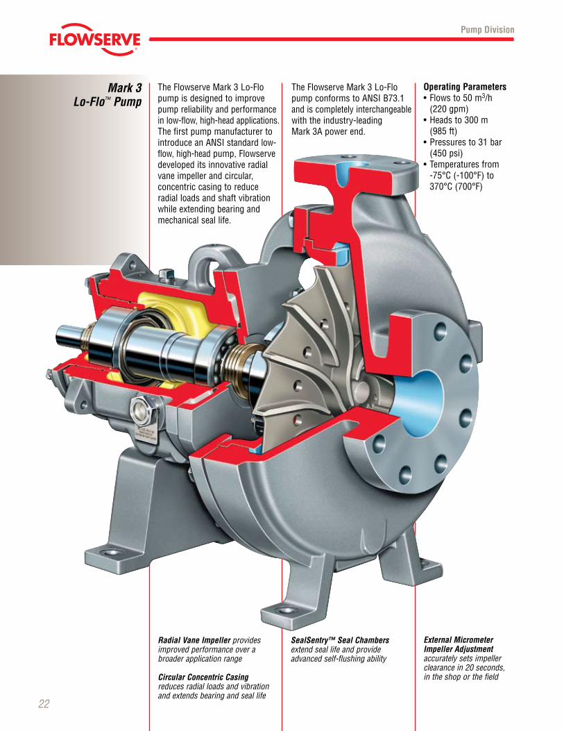
TheFlowserveMark3Lo-Flopump is designed to improve pump reliability and performance in low-flow, high-head applications. The first pump manufacturer to introduceanANSIstandardlow-flow, high-head pump, Flowserve developed its innovative radial vane impeller and circular, concentric casing to reduce radial loads and shaft vibration while extending bearing and mechanical seal life.
Mark 3Lo-Flo™ Pump
22
TheFlowserveMark3Lo-FlopumpconformstoANSIB73.1and is completely interchangeable with the industry-leading Mark3Apowerend.
Operating Parameters•Flowsto50m3/h
(220 gpm) •Headsto300m
(985 ft) •Pressuresto31bar
(450 psi) •Temperaturesfrom -75°C(-100°F)to370°C(700°F)
Pump Division
Radial Vane Impeller provides improved performance over a broader application range
Circular Concentric Casing reduces radial loads and vibration and extends bearing and seal life
SealSentry™ Seal Chambers extend seal life and provide advanced self-flushing ability
External Micrometer Impeller Adjustment accurately sets impeller clearance in 20 seconds, in the shop or the field
© TriComB2B, 2009, All Rights Reserved.
23
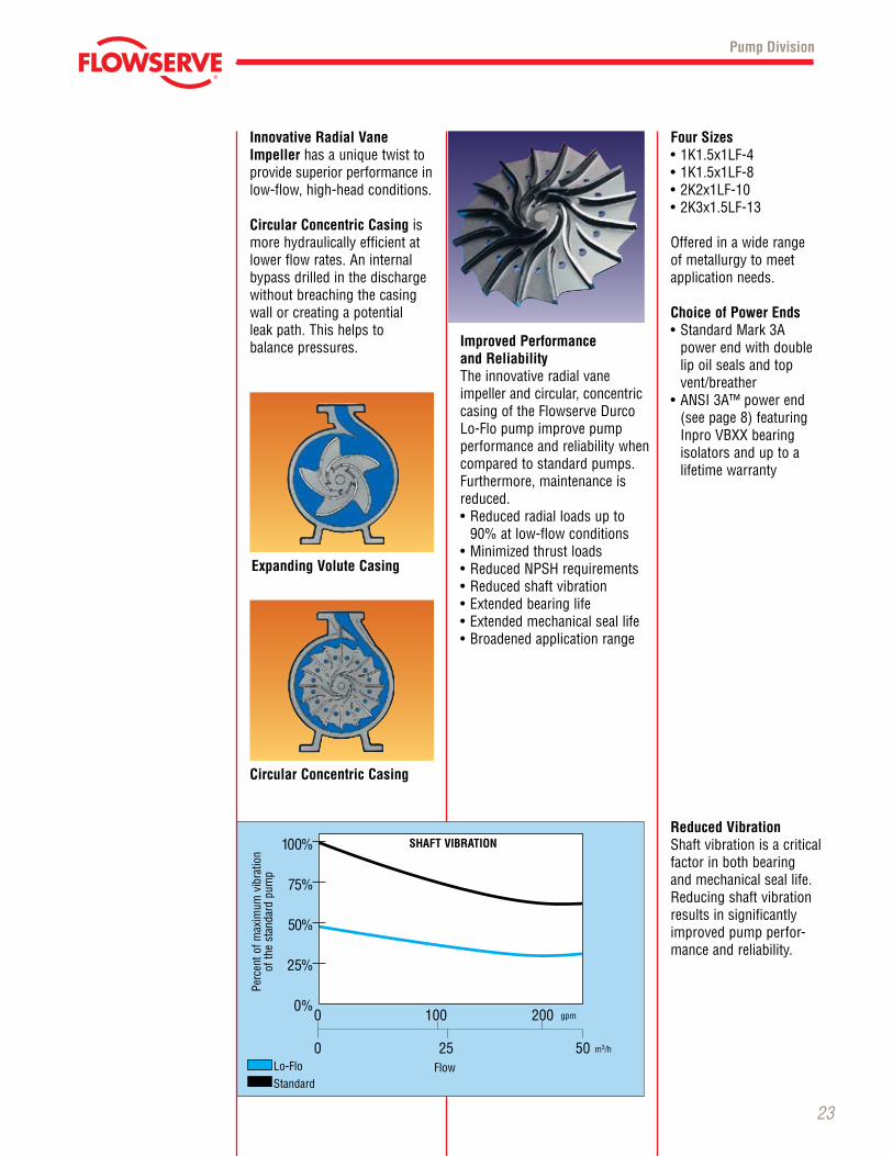
Innovative Radial Vane Impeller has a unique twist to provide superior performance in low-flow, high-head conditions.
Circular Concentric Casing is more hydraulically efficient at lower flow rates. An internal bypass drilled in the discharge without breaching the casing wall or creating a potential leak path. This helps to balance pressures. Improved Performance
and ReliabilityThe innovative radial vane impeller and circular, concentric casing of the Flowserve Durco Lo-Flopumpimprovepumpperformance and reliability when compared to standard pumps. Furthermore, maintenance is reduced.•Reducedradialloadsupto
90% at low-flow conditions•Minimizedthrustloads•ReducedNPSHrequirements•Reducedshaftvibration•Extendedbearinglife•Extendedmechanicalseallife•Broadenedapplicationrange
Four Sizes•1K1.5x1LF-4•1K1.5x1LF-8•2K2x1LF-10•2K3x1.5LF-13
Offeredinawiderangeof metallurgy to meet application needs.
Choice of Power Ends•StandardMark3A
power end with double lip oil seals and top vent/breather
•ANSI3A™powerend(see page 8) featuring InproVBXXbearingisolators and up to a lifetime warranty
Pump Division
Expanding Volute Casing
Circular Concentric Casing
100%
75%
50%
25%
0% 0 100 200
0 25 50 Lo-Flo Standard
Flow
Perc
ent o
f max
imum
vib
ratio
nof
the
stan
dard
pum
p
gpm
m3/h
SHAFT VIBRATIONReduced VibrationShaft vibration is a critical factor in both bearing and mechanical seal life. Reducingshaftvibrationresults in significantly improved pump perfor-mance and reliability.
© TriComB2B, 2009, All Rights Reserved.
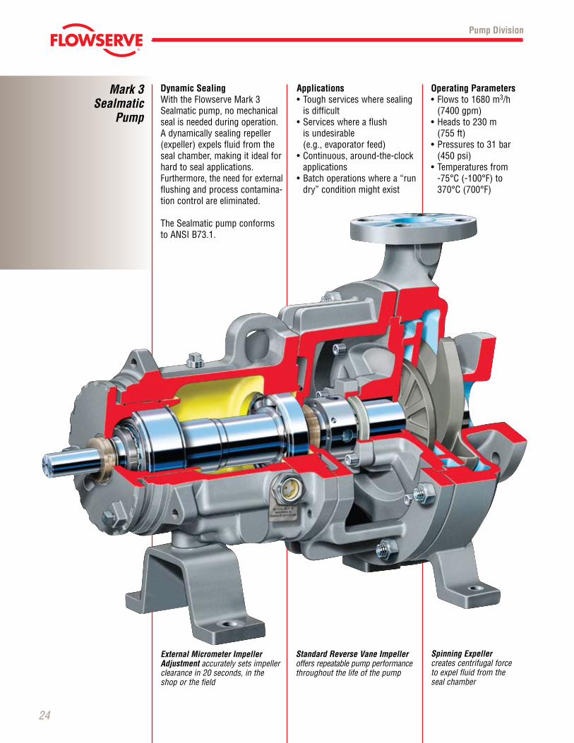
Dynamic SealingWiththeFlowserveMark3Sealmatic pump, no mechanical seal is needed during operation. A dynamically sealing repeller (expeller) expels fluid from the seal chamber, making it ideal for hard to seal applications. Furthermore, the need for external flushing and process contamina-tion control are eliminated.
The Sealmatic pump conforms toANSIB73.1.
Mark 3Sealmatic
Pump
24
Applications•Toughserviceswheresealing
is difficult•Serviceswhereaflush is undesirable (e.g., evaporator feed)•Continuous,around-the-clock
applications•Batchoperationswherea“rundry”conditionmightexist
Operating Parameters•Flowsto1680m3/h
(7400 gpm) •Headsto230m
(755 ft) •Pressuresto31bar
(450 psi) •Temperaturesfrom -75°C(-100°F)to370°C(700°F)
Pump Division
Standard Reverse Vane Impeller offers repeatable pump performance throughout the life of the pump
Spinning Expeller creates centrifugal force to expel fluid from the seal chamber
External Micrometer Impeller Adjustment accurately sets impeller clearance in 20 seconds, in the shop or the field
© TriComB2B, 2009, All Rights Reserved.
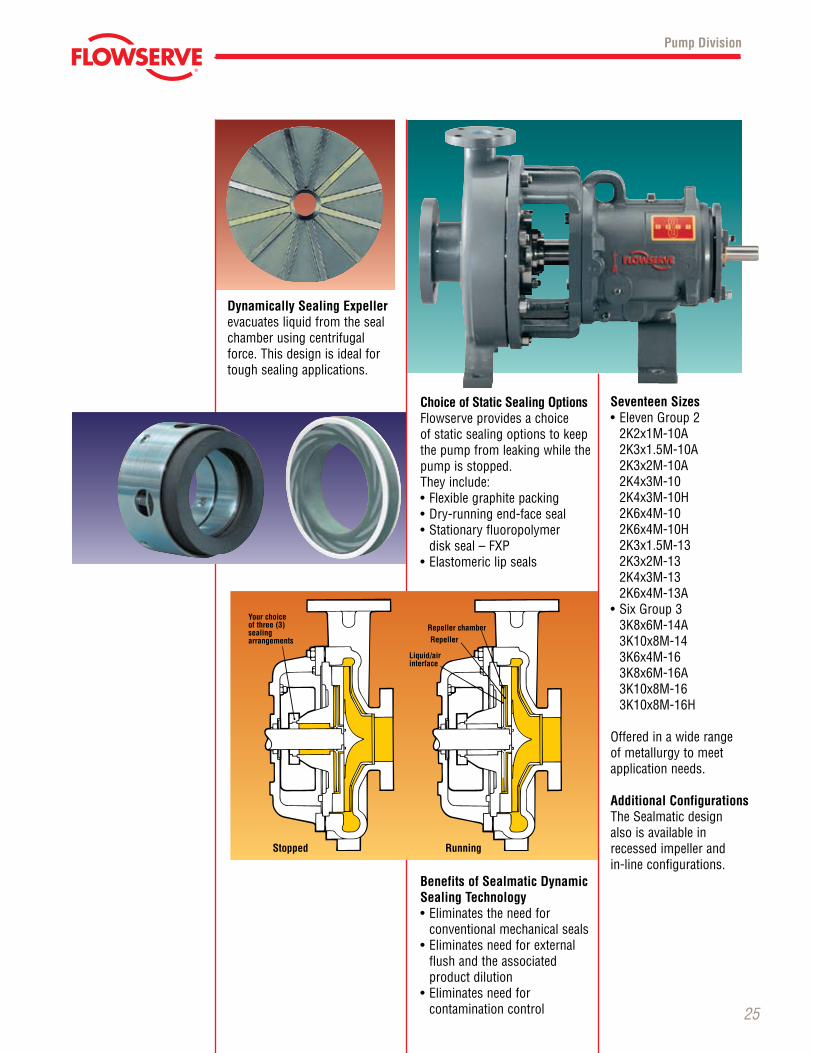
Your choice of three (3) sealing arrangements
Repeller chamber
Liquid/air interface
Repeller
RunningStopped
25
Choice of Static Sealing OptionsFlowserve provides a choice of static sealing options to keep the pump from leaking while the pump is stopped. They include: •Flexiblegraphitepacking•Dry-runningend-faceseal•Stationaryfluoropolymer
disk seal – FXP•Elastomericlipseals
Benefits of Sealmatic Dynamic Sealing Technology•Eliminatestheneedfor conventional mechanical seals•Eliminatesneedforexternal
flush and the associated product dilution
•Eliminatesneedfor contamination control
Dynamically Sealing Expeller evacuates liquid from the seal chamber using centrifugal force. This design is ideal for tough sealing applications.
Seventeen Sizes•ElevenGroup2 2K2x1M-10A 2K3x1.5M-10A 2K3x2M-10A 2K4x3M-10 2K4x3M-10H 2K6x4M-10 2K6x4M-10H 2K3x1.5M-13 2K3x2M-13 2K4x3M-13 2K6x4M-13A
•SixGroup3 3K8x6M-14A 3K10x8M-14 3K6x4M-16 3K8x6M-16A 3K10x8M-16 3K10x8M-16H
Offeredinawiderangeof metallurgy to meet application needs.
Additional Configurations The Sealmatic design also is available in recessed impeller and in-line configurations.
Pump Division
© TriComB2B, 2009, All Rights Reserved.
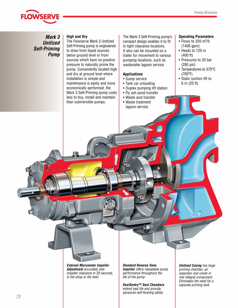
Unitized Casing has large priming chamber, air separator and volute in one integral component. Eliminates the need for a separateprimingtank
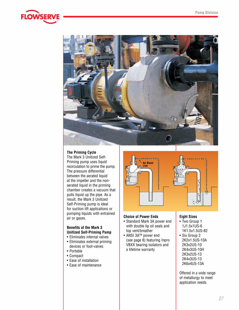
High and DryTheFlowserveMark3UnitizedSelf-Priming pump is engineered to draw from liquid sources below ground level or from sources which have no positive pressure to naturally prime the pump. Conveniently located high and dry at ground level where installation is simple and maintenance is easily and more economically performed, the Mark3Self-Primingpumpcostsless to buy, install and maintain than submersible pumps.
Mark 3Unitized
Self-Priming Pump
26
TheMark3Self-Primingpump’scompact design enables it to fit in tight clearance locations. Italsocanbemountedonatrailer for movement to various pumping locations, such as wastewater lagoon service.
Applications•Sumpservice•Tankcarunloading•Duplexpumpingliftstation•Flyashpondtransfer•Wasteacidtransfer•Wastetreatment
lagoon service
Operating Parameters•Flowsto320m3/h
(1400 gpm) •Headsto120m
(400 ft) •Pressuresto20bar
(285 psi) •Temperaturesto370°C(700°F)
•Staticsuctionliftto 6 m (20 ft)
Pump Division
Standard Reverse Vane Impeller offers repeatable pump performance throughout the life of the pump
SealSentry™ Seal Chambers extend seal life and provide advanced self-flushing ability
External Micrometer Impeller Adjustment accurately sets impeller clearance in 20 seconds, in the shop or the field
© TriComB2B, 2009, All Rights Reserved.
27
The Priming CycleTheMark3UnitizedSelf-Priming pump uses liquid recirculation to prime the pump. The pressure differential between the aerated liquid at the impeller and the non- aerated liquid in the priming chamber creates a vacuum that pulls liquid up the pipe. As a result,theMark3Unitized Self-Priming pump is ideal for suction lift applications or pumping liquids with entrained air or gases.
Benefits of the Mark 3 Unitized Self-Priming Pump•Eliminatesinternalvalves•Eliminatesexternalpriming
devices or foot-valves•Portable•Compact•Easeofinstallation•Easeofmaintenance
Choice of Power Ends •StandardMark3Apowerend
with double lip oil seals and top vent/breather
•ANSI3A™powerend (seepage8)featuringInproVBXXbearingisolatorsand a lifetime warranty
Eight Sizes•TwoGroup1
1J1.5x1US-6 1K1.5x1.5US-82
•SixGroup2 2K2x1.5US-10A 2K3x2US-10 2K4x3US-10H 2K3x2US-13 2K4x3US-13 2K6x4US-13A
Offeredinawiderangeof metallurgy to meet application needs.
Pump Division
Air Bleed Line
© TriComB2B, 2009, All Rights Reserved.
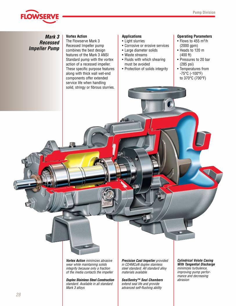
Vortex ActionTheFlowserveMark3RecessedImpellerpump combines the best design featuresoftheMark3ANSIStandard pump with the vortex action of a recessed impeller. These specific purpose features along with thick wall wet-end components offer extended service life when handling solid, stringy or fibrous slurries.
Mark 3Recessed
Impeller Pump
28
Applications•Lightslurries•Corrosiveorerosiveservices•Largediametersolids•Wastestreams•Fluidswithwhichshearing
must be avoided•Protectionofsolidsintegrity
Operating Parameters•Flowsto455m3/h
(2000 gpm) •Headsto120m
(400 ft) •Pressuresto20bar
(285 psi) •Temperaturesfrom -75°C(-100°F) to370°C(700°F)
Pump Division
Vortex Action minimizes abrasive wear while maintaining solids integrity because only a fraction of the media contacts the impeller
Duplex Stainless Steel Construction standard. Available in all standard Mark3alloys
Precision Cast Impeller provided in CD4MCuN duplex stainless steel standard. All standard alloy materials available
SealSentry™ Seal Chambers extend seal life and provide advanced self-flushing ability
Cylindrical Volute Casing With Tangential Discharge minimizes turbulence, improving pump perfor-mance and decreasing abrasion
© TriComB2B, 2009, All Rights Reserved.
29
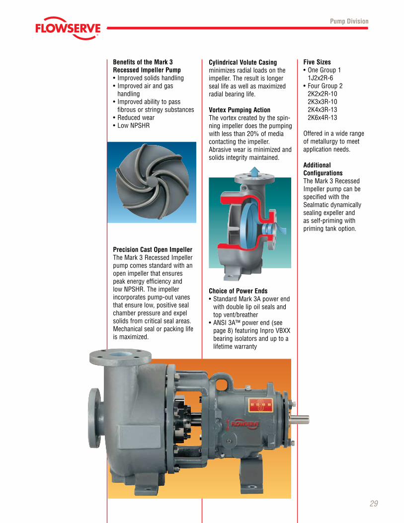
Precision Cast Open ImpellerTheMark3RecessedImpellerpump comes standard with an open impeller that ensures peak energy efficiency and lowNPSHR.Theimpellerincorporates pump-out vanes that ensure low, positive seal chamber pressure and expel solids from critical seal areas. Mechanicalsealorpackinglifeis maximized.
Cylindrical Volute Casing minimizes radial loads on the impeller. The result is longer seal life as well as maximized radial bearing life.
Vortex Pumping ActionThe vortex created by the spin-ning impeller does the pumping with less than 20% of media contacting the impeller. Abrasive wear is minimized and solids integrity maintained.
Choice of Power Ends •StandardMark3Apowerend
with double lip oil seals and top vent/breather
•ANSI3A™powerend(seepage8)featuringInproVBXXbearing isolators and up to a lifetime warranty
Pump Division
Benefits of the Mark 3 Recessed Impeller Pump• Improvedsolidshandling• Improvedairandgas
handling• Improvedabilitytopass
fibrous or stringy substances•Reducedwear•LowNPSHR
Five Sizes•OneGroup1 1J2x2R-6
•FourGroup2 2K2x2R-10 2K3x3R-10 2K4x3R-13 2K6x4R-13
Offeredinawiderangeof metallurgy to meet application needs.
Additional Configurations TheMark3RecessedImpellerpumpcanbespecified with the Sealmatic dynamically sealing expeller and as self-priming with priming tank option.
© TriComB2B, 2009, All Rights Reserved.
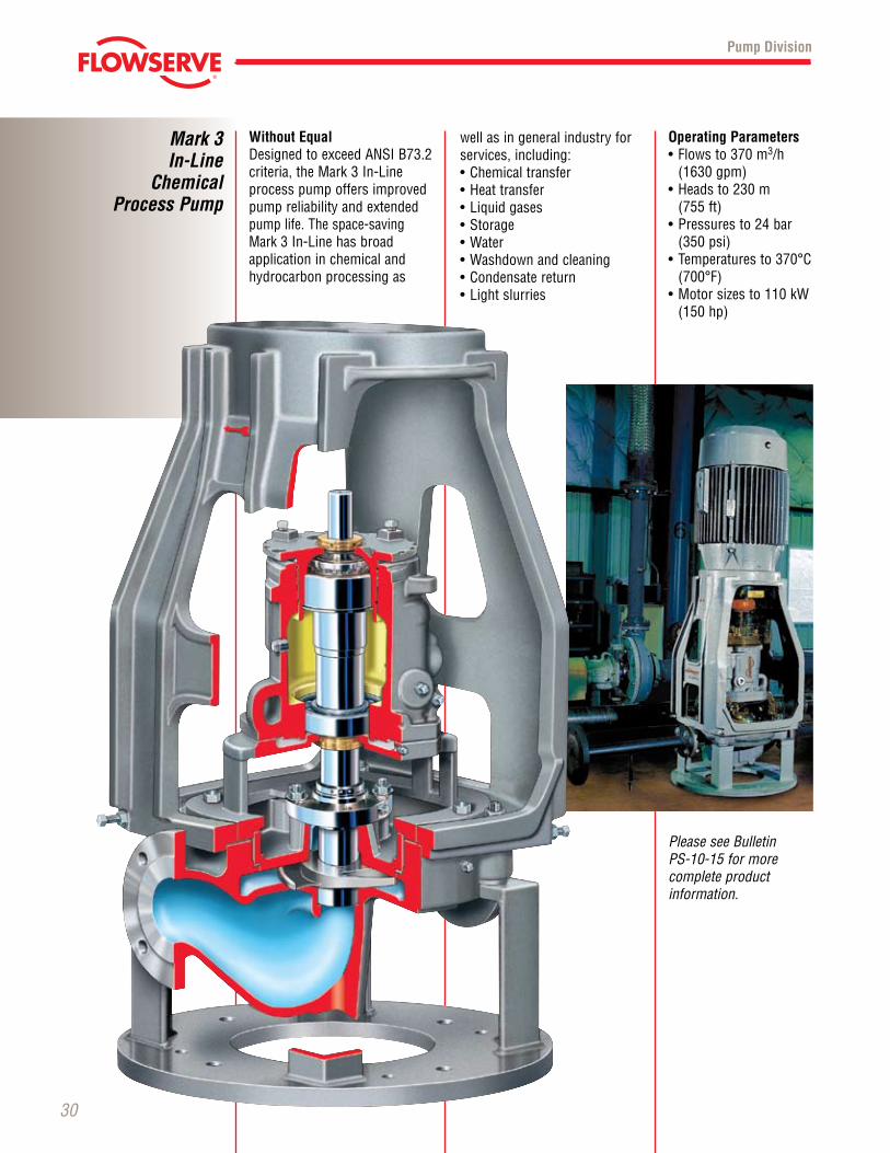
Without EqualDesignedtoexceedANSIB73.2criteria,theMark3In-Line process pump offers improved pump reliability and extended pump life. The space-saving Mark3In-Linehasbroad application in chemical and hydrocarbon processing as
Mark 3 In-Line
Chemical Process Pump
30
well as in general industry for services, including:•Chemicaltransfer•Heattransfer•Liquidgases•Storage•Water•Washdownandcleaning•Condensatereturn•Lightslurries
Operating Parameters•Flowsto370m3/h
(1630 gpm)•Headsto230m (755 ft)•Pressuresto24bar
(350 psi)•Temperaturesto370°C(700°F)
•Motorsizesto110kW(150 hp)
Pump Division
PleaseseeBulletin PS-10-15formore complete productinformation.
© TriComB2B, 2009, All Rights Reserved.
31
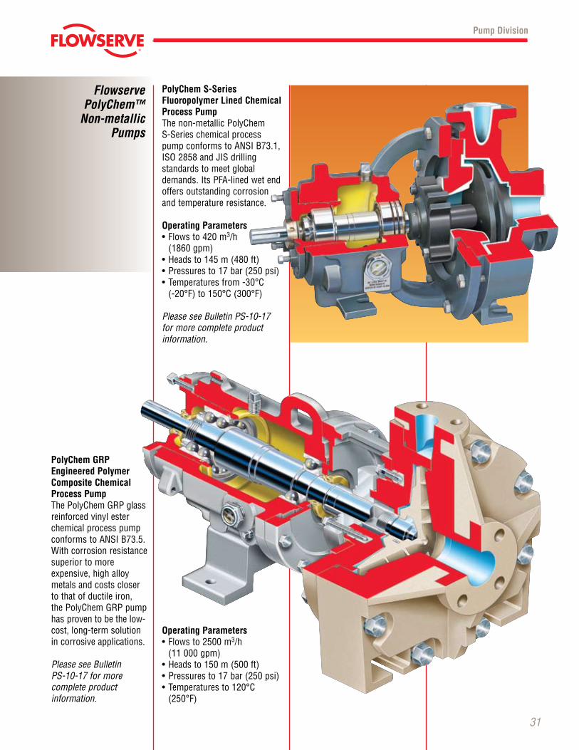
PolyChem S-Series Fluoropolymer Lined Chemical Process PumpThe non-metallic PolyChem S-Series chemical process pumpconformstoANSIB73.1,ISO2858andJISdrilling standards to meet global demands.ItsPFA-linedwetendoffers outstanding corrosion and temperature resistance.
Operating Parameters•Flowsto420m3/h
(1860 gpm)•Headsto145m(480ft)•Pressuresto17bar(250psi)•Temperaturesfrom-30°C (-20°F)to150°C(300°F)
PleaseseeBulletinPS-10-17 for more complete product information.
Operating Parameters•Flowsto2500m3/h
(11 000 gpm)•Headsto150m(500ft)•Pressuresto17bar(250psi)•Temperaturesto120°C(250°F)
PolyChem GRP Engineered Polymer Composite Chemical Process PumpThePolyChemGRPglass reinforced vinyl ester chemical process pump conformstoANSIB73.5.Withcorrosionresistancesuperior to more expensive, high alloy metals and costs closer to that of ductile iron, thePolyChemGRPpumphas proven to be the low-cost, long-term solution in corrosive applications.
PleaseseeBulletin PS-10-17formore complete product information.
Pump Division
FlowservePolyChem™
Non-metallic Pumps
© TriComB2B, 2009, All Rights Reserved.
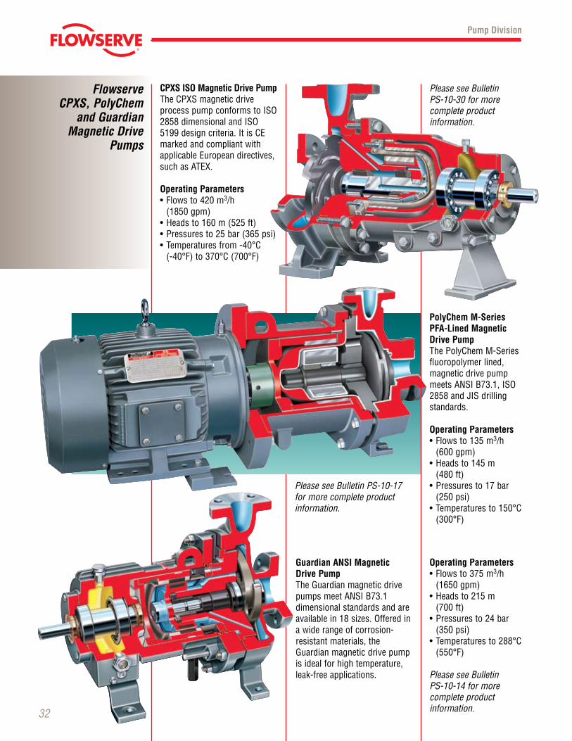
CPXS ISO Magnetic Drive PumpThe CPXS magnetic drive processpumpconformstoISO2858dimensionalandISO5199designcriteria.ItisCEmarked and compliant with applicable European directives, such as ATEX.
Operating Parameters•Flowsto420m3/h
(1850 gpm)•Headsto160m(525ft)•Pressuresto25bar(365psi)•Temperaturesfrom-40°C (-40°F)to370°C(700°F)
Guardian ANSI Magnetic Drive PumpTheGuardianmagneticdrivepumpsmeetANSIB73.1dimensional standards and are availablein18sizes.Offeredina wide range of corrosion- resistant materials, the Guardianmagneticdrivepumpis ideal for high temperature, leak-free applications.
PolyChem M-Series PFA-Lined Magnetic Drive PumpThePolyChemM-Seriesfluoropolymer lined, magnetic drive pump meetsANSIB73.1,ISO2858andJISdrillingstandards.
Operating Parameters•Flowsto135m3/h
(600 gpm)•Headsto145m
(480 ft)•Pressuresto17bar
(250 psi)•Temperaturesto150°C(300°F)
Operating Parameters•Flowsto375m3/h
(1650 gpm)•Headsto215m
(700 ft)•Pressuresto24bar
(350 psi)•Temperaturesto288°C(550°F)
PleaseseeBulletin PS-10-14formorecomplete productinformation.
Flowserve CPXS, PolyChem
and Guardian Magnetic Drive
Pumps
32
Pump Division
PleaseseeBulletin PS-10-30formore complete product information.
PleaseseeBulletinPS-10-17for more complete product information.
© TriComB2B, 2009, All Rights Reserved.
33
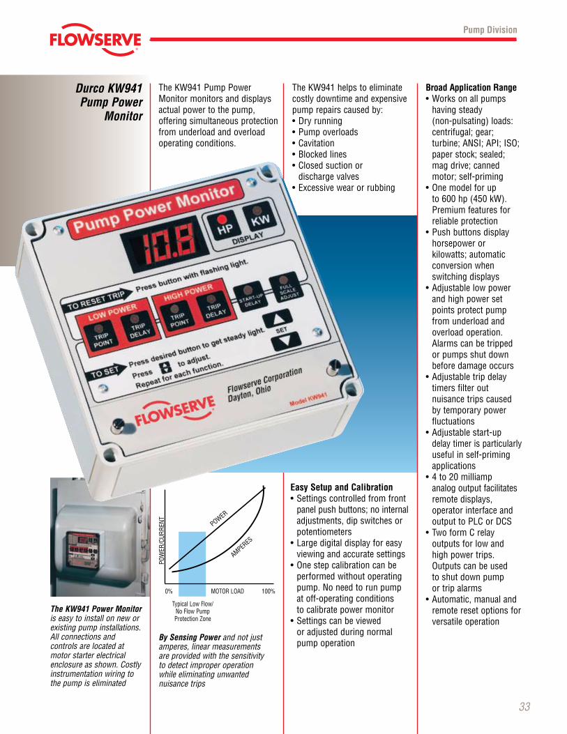
TheKW941PumpPowerMonitormonitorsanddisplaysactual power to the pump, offering simul taneous protection from underload and overload operating conditions.
Pump Division
Durco KW941Pump Power
Monitor
Broad Application Range•Worksonallpumps
having steady (non-pulsating) loads: cen trifu gal; gear; turbine;ANSI;API;ISO;paper stock; sealed; mag drive; canned motor; self-priming
•Onemodelforup to600hp(450kW).Premium features for reliable protection
•Pushbuttonsdisplayhorse power or kilo watts; automatic conversion when switching displays
•Adjustablelowpowerand high power set points protect pump from underload and over load operation. Alarms can be tripped or pumps shut down before damage occurs
•Adjustabletripdelaytimers filter out nuisance trips caused by tem po rary power fluctuations
•Adjustablestart-updelay timer is particularly useful in self-priming applications
•4to20milliamp analog output facilitates remote displays, operator inter face and outputtoPLCorDCS
•TwoformCrelay out puts for low and high power trips. Outputscanbeused to shut down pump or trip alarms
•Automatic,manualandremote reset options for versatile operation
TheKW941helpstoeliminatecostly down time and expensive pump repairs caused by:•Dryrunning•Pumpoverloads•Cavitation•Blockedlines•Closedsuctionor
discharge valves•Excessivewearorrubbing
The KW941 Power Monitor is easy to install on new or existing pump installations. All connections and con trols are located at motor starter electrical enclosure as shown. Costly instrumenta tion wiring to the pump is eliminated
POWER
AMPERES
0% MOTORLOAD100%
TypicalLowFlow/NoFlowPumpProtectionZone
POWER/CURRENT
By Sensing Powerandnotjustamperes, linear measurements are pro vided with the sensitivity to detect improper opera tion while eliminating unwanted nuisance trips
Easy Setup and Calibration•Settingscontrolledfromfront
panel push buttons; no internal adjustments, dip switches or potentio meters
•Largedigitaldisplayforeasyviewing and accurate settings
•Onestepcalibrationcanbeperformed without operat ing pump.Noneedtorunpumpat off-operating conditions to calibrate power monitor
•Settingscanbeviewed or adjusted during normal pump operation
© TriComB2B, 2009, All Rights Reserved.
Flowserve CPX and FRBH
Process Pumps
34
Pump Division
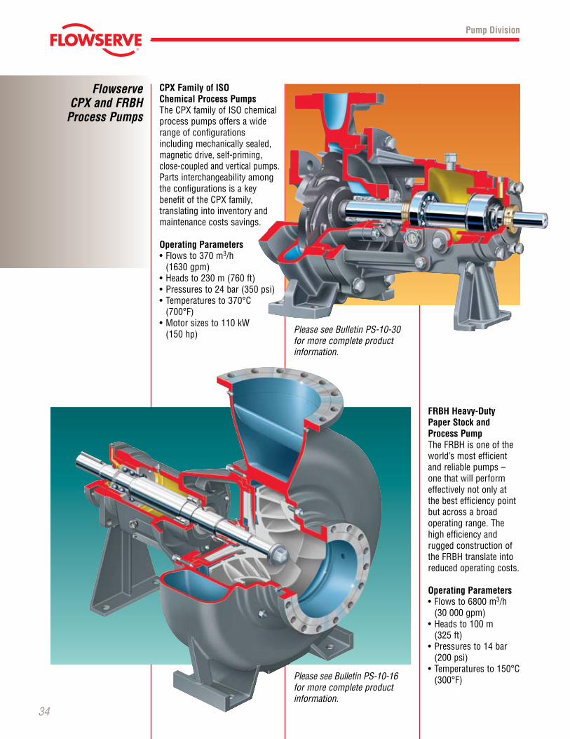
CPX Family of ISO Chemical Process PumpsTheCPXfamilyofISOchemicalprocess pumps offers a wide range of configurations including mechanically sealed, magnetic drive, self-priming, close-coupled and vertical pumps. Parts interchangeability among the configurations is a key benefit of the CPX family, translating into inventory and maintenance costs savings.
Operating Parameters•Flowsto370m3/h
(1630 gpm)•Headsto230m(760ft)•Pressuresto24bar(350psi)•Temperaturesto370°C(700°F)
•Motorsizesto110kW (150 hp)
FRBH Heavy-Duty Paper Stock and Process PumpTheFRBHisoneoftheworld’smostefficientand reliable pumps – one that will perform effectively not only at the best efficiency point but across a broad operating range. The high efficiency and rugged construction of theFRBHtranslateintoreduced operating costs.
Operating Parameters•Flowsto6800m3/h
(30 000 gpm)•Headsto100m
(325 ft)•Pressuresto14bar
(200 psi)•Temperaturesto150°C(300°F)
PleaseseeBulletinPS-10-30for more complete product information.
PleaseseeBulletinPS-10-16for more complete product information.
© TriComB2B, 2009, All Rights Reserved.
Pump Division
Global Engineered Services
and Support
Total Cost Reduction
Asset Management
ProductLifeCycle
PerformanceRe-rates
Site Diagnostics
Repair Services
Energy Management
SpareParts
Maintenance Contracts
Materials Upgrades
TurnkeyServices
Field Repairs
Installation
ProjectSupervision
Commissioning
Equipment Upgrades
Condition Monitoring
Systems Analysis
Field Machining
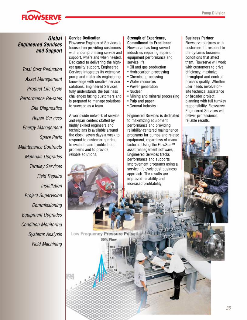
Service DedicationFlowserve Engineered Services is focused on providing customers with uncompromising service and support, where and when needed. Dedicated to delivering the high-est quality support, Engineered Services integrates its extensive pump and materials engineering knowledge with creative service solutions. Engineered Services fully understands the business challenges facing customers and is prepared to manage solutions to succeed as a team.
A worldwide network of service and repair centers staffed by highly skilled engineers and technicians is available around the clock, seven days a week to respond to customer queries, to evaluate and troubleshoot problems and to provide reliable solutions.
Business Partner Flowserve partners with customers to respond to the dynamic business conditions that affect them. Flowserve will work with customers to drive efficiency, maximize throughput and control processquality.Whetheruser needs involve on- site technical assistance or broader project planning with full turnkey responsibility, Flowserve Engineered Services will deliver professional, reliable results.
35
Strength of Experience, Commitment to ExcellenceFlowserve has long served industries requiring superior equipment performance and service life.•Oilandgasproduction•Hydrocarbonprocessing•Chemicalprocessing•Waterresources•Powergeneration•Nuclear•Miningandmineralprocessing•Pulpandpaper•Generalindustry
Engineered Services is dedicated to maximizing equipment performance and providing reliability-centered maintenance programs for pumps and related equipment, regardless of manu-facturer.UsingtheFlowStar™asset management software, Engineered Services tracks performance and supports improvement programs using a service life cycle cost business approach. The results areimproved reliability and increased profitability.
Printed in U.S.A.December 2009
© Flowserve Corporation
© TriComB2B, 2009, All Rights Reserved.
To find your local Flowserve representative please use the Sales Support Locator System
found at www.flowserve.com
Or call toll free: 1 800 728 PUMP (7867)
Your local Flowserve representative:
Pump Division
USA and CanadaFlowserve Corporation5215 North O’Connor Blvd.Suite 2300Irving, Texas 75039-5421 USATelephone: 1 937 890 5839
Europe, Middle East, Africa Flowserve CorporationGebouw HagepointWestbroek 39-514822 ZX Breda NetherlandsTelephone: 31 76 502 8920
Latin America Flowserve CorporationBoulevard del Cafetal Edificio Ninina, Local 7 El Cafetal - Caracas Venezuela 1061 Telephone: 58 212 985 3092 Telefax: 58 212 985 1007
Asia Pacific Flowserve Pte. Ltd.10 Tuas Loop Singapore 637345 Telephone: 65 6771 0600Telefax: 65 6779 4607
Flowserve... Supporting Our CustomersWith The World’s LeadingPump Brands
Jeumont-Schneider™Jeumont-Schneider™


![NORTA MIT PRESENTATION.pptx [Read-Only] · • Centrifugal pumps • Side channel pumps • Gear pumps • Screw pumps • Single screw pumps • Piston pumps • Vacuum pumps •](https://img.pdfslide.net/doc/110x75/5ec27ab9e3ef591d10504c3a/norta-mit-read-only-a-centrifugal-pumps-a-side-channel-pumps-a-gear-pumps.jpg)