Embed Size (px)
DESCRIPTION
tomberlin punisher go kart
Citation preview
Tomberlin OutdoorPunisher Service Manual
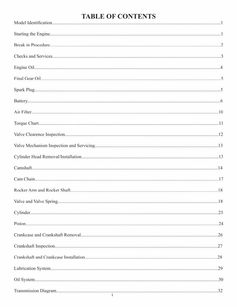
TABLE OF CONTENTSModel Identifi cation.................................................................................................................................................1
Starting the Engine...................................................................................................................................................1
Break in Procedure...................................................................................................................................................2
Checks and Services.................................................................................................................................................3
Engine Oil................................................................................................................................................................4
Final Gear Oil...........................................................................................................................................................5
Spark Plug................................................................................................................................................................5
Battery......................................................................................................................................................................6
Air Filter.................................................................................................................................................................10
Torque Chart...........................................................................................................................................................11
Valve Clearence Inspection....................................................................................................................................12
Valve Mechanism Inspection and Servicing..........................................................................................................13
Cylinder Head Removal/Installation......................................................................................................................13
Camshaft................................................................................................................................................................14
Cam Chain..............................................................................................................................................................17
Rocker Arm and Rocker Shaft...............................................................................................................................18
Valve and Valve Spring..........................................................................................................................................18
Cylinder..................................................................................................................................................................23
Piston......................................................................................................................................................................24
Crankcase and Crankshaft Removal......................................................................................................................26
Crankshaft Inspection............................................................................................................................................27
Crankshaft and Crankcase Installation..................................................................................................................28
Lubrication System................................................................................................................................................29
Oil System..............................................................................................................................................................30
Transmission Diagram...........................................................................................................................................32i
Transmission Diagram...........................................................................................................................................32i
Transmission Diagram...........................................................................................................................................32
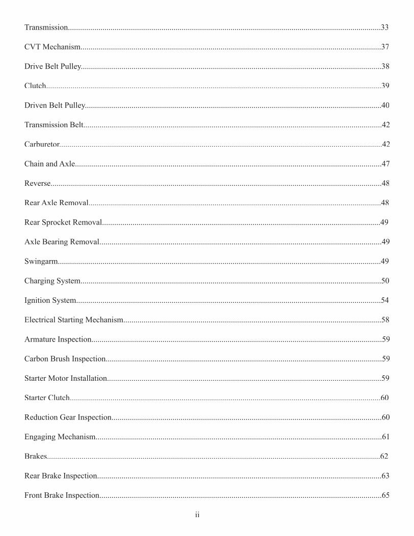
Transmission..........................................................................................................................................................33
CVT Mechanism....................................................................................................................................................37
Drive Belt Pulley....................................................................................................................................................38
Clutch.....................................................................................................................................................................39
Driven Belt Pulley..................................................................................................................................................40
Transmission Belt...................................................................................................................................................42
Carburetor...............................................................................................................................................................42
Chain and Axle.......................................................................................................................................................47
Reverse...................................................................................................................................................................48
Rear Axle Removal................................................................................................................................................48
Rear Sprocket Removal.........................................................................................................................................49
Axle Bearing Removal...........................................................................................................................................49
Swingarm...............................................................................................................................................................49
Charging System....................................................................................................................................................50
Ignition System......................................................................................................................................................54
Electrical Starting Mechanism...............................................................................................................................58
Armature Inspection...............................................................................................................................................59
Carbon Brush Inspection........................................................................................................................................59
Starter Motor Installation.......................................................................................................................................59
Starter Clutch.........................................................................................................................................................60
Reduction Gear Inspection.....................................................................................................................................60
Engaging Mechanism.............................................................................................................................................61
Brakes....................................................................................................................................................................62
Rear Brake Inspection............................................................................................................................................63
Front Brake Inspection...........................................................................................................................................65
ii
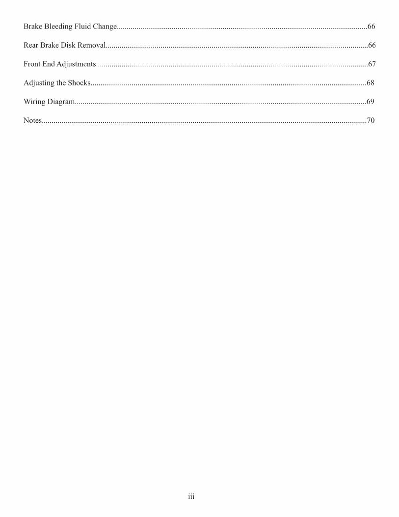
Brake Bleeding Fluid Change................................................................................................................................66
Rear Brake Disk Removal......................................................................................................................................66
Front End Adjustments...........................................................................................................................................67
Adjusting the Shocks.............................................................................................................................................68
Wiring Diagram.....................................................................................................................................................69
Notes......................................................................................................................................................................70
iii
MODEL IDENTIFICATION
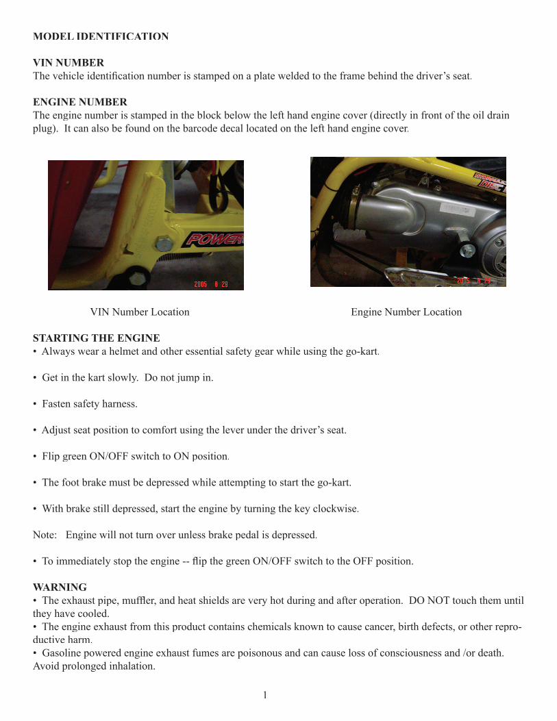
VIN NUMBERThe vehicle identifi cation number is stamped on a plate welded to the frame behind the driver’s seat.
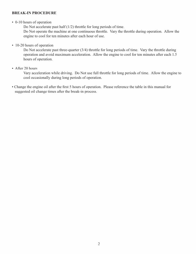
ENGINE NUMBERThe engine number is stamped in the block below the left hand engine cover (directly in front of the oil drain plug). It can also be found on the barcode decal located on the left hand engine cover.
VIN Number Location Engine Number Location
STARTING THE ENGINE• Always wear a helmet and other essential safety gear while using the go-kart.
• Get in the kart slowly. Do not jump in.
• Fasten safety harness.
• Adjust seat position to comfort using the lever under the driver’s seat.
• Flip green ON/OFF switch to ON position.
• The foot brake must be depressed while attempting to start the go-kart.
• With brake still depressed, start the engine by turning the key clockwise.
Note: Engine will not turn over unless brake pedal is depressed.
• To immediately stop the engine -- fl ip the green ON/OFF switch to the OFF position.
WARNING • The exhaust pipe, muffl er, and heat shields are very hot during and after operation. DO NOT touch them until they have cooled.• The engine exhaust from this product contains chemicals known to cause cancer, birth defects, or other repro-ductive harm.• Gasoline powered engine exhaust fumes are poisonous and can cause loss of consciousness and /or death. Avoid prolonged inhalation.
1
BREAK-IN PROCEDURE
• 0-10 hours of operation Do Not accelerate past half (1/2) throttle for long periods of time. Do Not operate the machine at one continuous throttle. Vary the throttle during operation. Allow the engine to cool for ten minutes after each hour of use.
• 10-20 hours of operation Do Not accelerate past three-quarter (3/4) throttle for long periods of time. Vary the throttle during operation and avoid maximum acceleration. Allow the engine to cool for ten minutes after each 1.5 hours of operation.
• After 20 hours Vary acceleration while driving. Do Not use full throttle for long periods of time. Allow the engine to cool occasionally during long periods of operation.
• Change the engine oil after the fi rst 5 hours of operation. Please reference the table in this manual for suggested oil change times after the break-in process.
2
CHECKS AND SERVICESThe maintenance intervals in the following table are based upon average riding conditions. Riding in unusually dusty areas require more frequent servicing.
Items Initial Service
Daily Monthly Quarterly Yearly
Tire Pressure Inspect InspectChassis Inspect InspectFasteners Inspect InspectBrake Performance Inspect InspectBrake Fluid InspectAir Filter ChangeCarburetor Inspect InspectSpark Plug ChangeDrive Chain Inspect Inspect Inspect AdjustEngine Oil Replace Inspect ReplaceGearbox Oil Inspect ReplaceValve Clearance AdjustFuel Line Inspect Inspect InspectExhaust Inspect InspectBattery Inspect Inspect
Interval(Months)
ServiceDate
Service Performed By: Type of Service
136121824303642485460
MAINTENANCE AND TUNE-UP PROCEDUREThis section describes the servicing procedures for each item in the CHECKS and SERVICES table.
ENGINE OIL API Classifi cation SF – SG (SAE 15W – 40)
It is important to inspect the engine oil before each period of operation. The engine oil should be changed every 50 hours.
CHECKING THE ENGINE OIL:• Place unit on fl at surface.
• Remove dipstick and wipe off with a clean cloth.
• Return the dipstick to the hole. Push the dipstick in until the threads prevent it from going any farther. Do Not screw the dipstick into place while attempting to check the oil. Doing so will cause a false reading.
• Check oil level to see if it is between min and max indicators.
• Add oil as necessary to reach the required level.
- Return the dipstick to its original position. Be sure to tighten the cap into place after checking the oil.
CHANGING THE ENGINE OIL:• Run unit for at least 5 minutes or until warm, shut off.
• Place suitable container for draining oil beneath engine.
- Container should be capable of holding at least 1 gallon.
- Warning - Engine components may be hot. Use caution while attempting to change the oil.
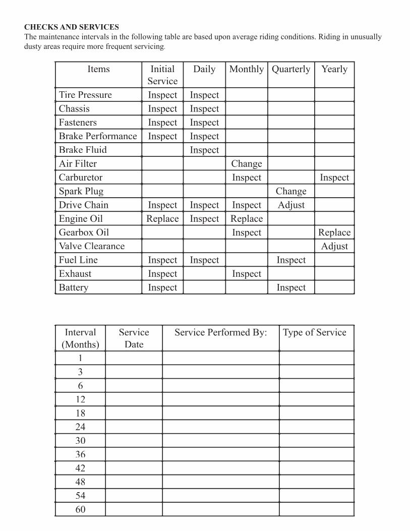
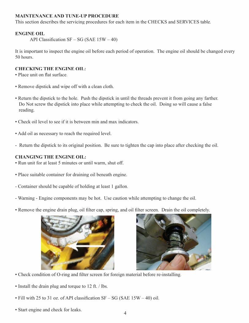
• Remove the engine drain plug, oil fi lter cap, spring, and oil fi lter screen. Drain the oil completely.
• Check condition of O-ring and fi lter screen for foreign material before re-installing.
• Install the drain plug and torque to 12 ft. / lbs.
• Fill with 25 to 31 oz. of API classifi cation SF – SG (SAE 15W – 40) oil.
• Start engine and check for leaks.4
• Shut off engine and check the oil level with dipstick, do NOT screw the dipstick in when taking this reading, doing so may cause a false reading. Add oil if necessary to reach safe amount; Do Not overfi ll.
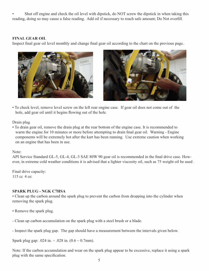
FINAL GEAR OILInspect fi nal gear oil level monthly and change fi nal gear oil according to the chart on the previous page..
• To check level, remove level screw on the left rear engine case. If gear oil does not come out of the hole, add gear oil until it begins fl owing out of the hole.
Drain plug• To drain gear oil, remove the drain plug at the rear bottom of the engine case. It is recommended to warm the engine for 10 minutes or more before attempting to drain fi nal gear oil. Warning - Engine components will be extremely hot after the kart has been running. Use extreme caution when working on an engine that has been in use.
Note:API Service Standard GL-5, GL-4, GL-3 SAE 80W 90 gear oil is recommended in the fi nal drive case. How-ever, in extreme cold weather conditions it is advised that a lighter viscosity oil, such as 75 weight oil be used .
Final drive capacity: 115 cc 4 oz.
SPARK PLUG - NGK C7HSA• Clean up the carbon around the spark plug to prevent the carbon from dropping into the cylinder when removing the spark plug.
• Remove the spark plug.
- Clean up carbon accumulation on the spark plug with a steel brush or a blade.
- Inspect the spark plug gap. The gap should have a measurement between the intervals given below.
Spark plug gap: .024 in. ~ .028 in. (0.6 ~ 0.7mm).
Note: If the carbon accumulation and wear on the spark plug appear to be excessive, replace it using a spark plug with the same specifi cation.
5
FILLING THE BATTERYThe following procedure should only be performed by an adult utilizing extreme caution. While attempting this procedure, individuals should wear rubber gloves, eye protection, and have water available in case the electrolyte solution comes into contact with skin or eyes. Children should not attempt to complete this procedure, and should NOT be allowed near the area when attempting to fi ll the battery. This procedure should be completed fi rst so that the battery is charged when the kart assembly is complete
WARNING: POISON - CAUSES SEVERE BURNSContains sulfuric acid. Avoid contact with skin, eyes, and clothing. To prevent accidents, rinse the empty electrolyte solution container with water after use. - If solution comes in contact with the skin, fl ush the area with water. - If solution is swallowed contact a physician immediately. - If solution comes in contact with the eyes fl ush with water for fi fteen minutes. Get immediate medical attention. KEEP OUT OF REACH OF CHILDREN
PROCEDURE- This procedure should be performed in a location out of reach of children and animals.
- Remove the battery and the electrolyte solution from the shipping crate.
- Place the battery on a level surface and remove the metallic sealing from the top.
- Holding the electrolyte container upside down so the sealed openings are facing the ground, align each sealed opening of the bottles with the corresponding openings on top of the battery terminal.
- Strongly push the electrolyte container into the openings of the battery terminal so that the all of the seals on the electrolyte container break, allowing electrolyte solution to fl ow into the battery. Do NOT attempt to puncture the electrolyte container unless the six sealed openings are properly aligned with the six openings on the top of the battery terminal.
- Air bubbles will begin rising from each opening of the electrolyte solution when they are punctured.
- If air bubbles are not rising in each individual tube, tap the top side of the electrolyte bottles.
- Leave the electrolyte bottles in their draining position until all of the electrolyte solution has drained. Do NOT attempt to remove the electrolyte bottles while they are draining.
- Do NOT attempt to puncture or cut any part of the electrolyte container.
- Do NOT allow children near the battery at any point during the installation process.
- When the electrolyte solution has fi nished draining, pull the bottles gently from the top of the battery terminal and properly discard in a location out of reach of children or animals.
6
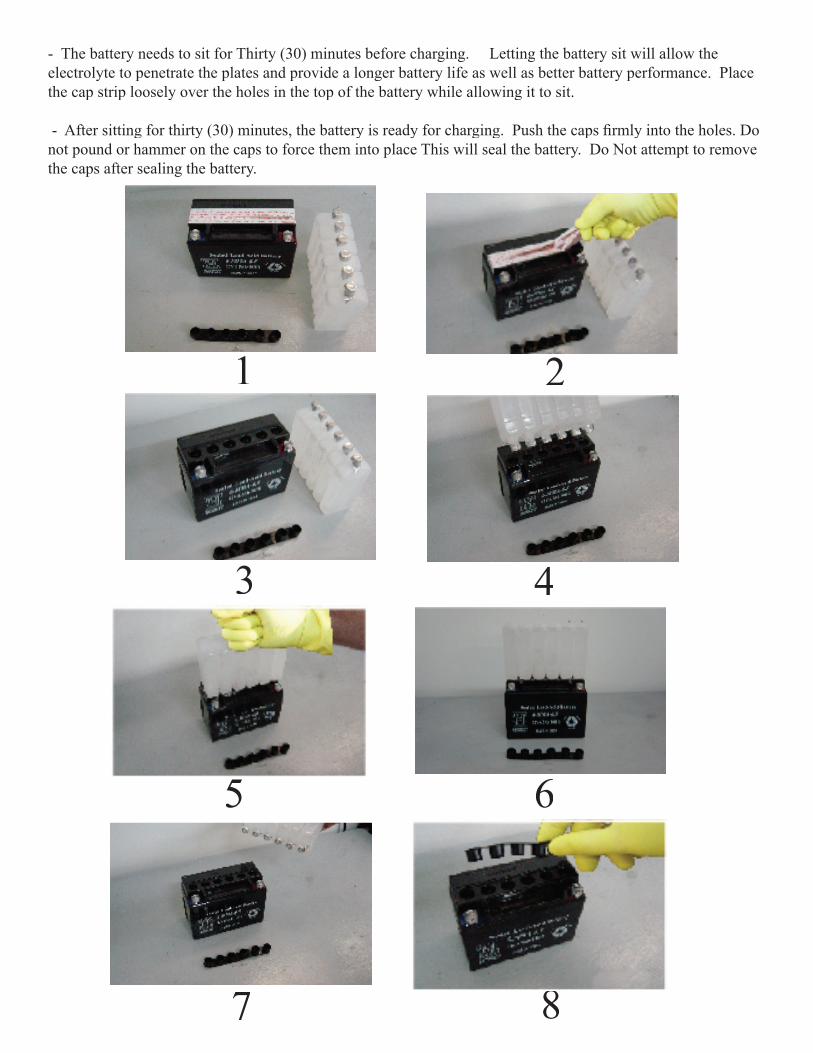
- The battery needs to sit for Thirty (30) minutes before charging. Letting the battery sit will allow the electrolyte to penetrate the plates and provide a longer battery life as well as better battery performance. Place the cap strip loosely over the holes in the top of the battery while allowing it to sit.
- After sitting for thirty (30) minutes, the battery is ready for charging. Push the caps fi rmly into the holes. Do not pound or hammer on the caps to force them into place This will seal the battery. Do Not attempt to remove the caps after sealing the battery.
1 2
3 4
5 6
7 8
WARNING: Do NOT open sealed caps to add water to the battery.- Batteries contain sulfuric acid. Eye protection should ALWAYS be used when working around battery acid. - While attaching the red and black cables for charging, be sure that the charger is not plugged into the outlet.- Charge the battery in a well ventilated area out of reach of children and animals.- Do NOT smoke around batteries- Do NOT expose batteries to open fl ames
CHARGING THE BATTERY- The battery must be charged before use.
- Connect the positive (+) red clamp from the battery charger to the positive (+) pole of the battery.
- Connect the negative (-) black clamp from the battery charger to the negative pole of the battery.
- Do NOT plug the charger into the outlet until the clamps have been placed in their proper location on the battery.
- The battery should charge between 500-700 milliampere for 6-10 hours.
- When the battery has fi nished charging, unplug the charger from the outlet, then proceed to remove the clamps from the charger.
Note: Always keep the battery clean. Apply dielectric grease around the battery terminals to prevent corrosion.
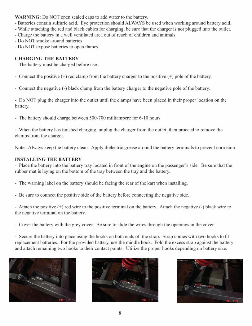
INSTALLING THE BATTERY- Place the battery into the battery tray located in front of the engine on the passenger’s side. Be sure that the rubber mat is laying on the bottom of the tray between the tray and the battery.
- The warning label on the battery should be facing the rear of the kart when installing.
- Be sure to connect the positive side of the battery before connecting the negative side.
- Attach the positive (+) red wire to the positive terminal on the battery. Attach the negative (-) black wire to the negative terminal on the battery.
- Cover the battery with the grey cover. Be sure to slide the wires through the openings in the cover.
- Secure the battery into place using the hooks on both ends of the strap. Strap comes with two hooks to fi t replacement batteries. For the provided battery, use the middle hook. Fold the excess strap against the battery and attach remaining two hooks to their contact points. Utilize the proper hooks depending on battery size.
8
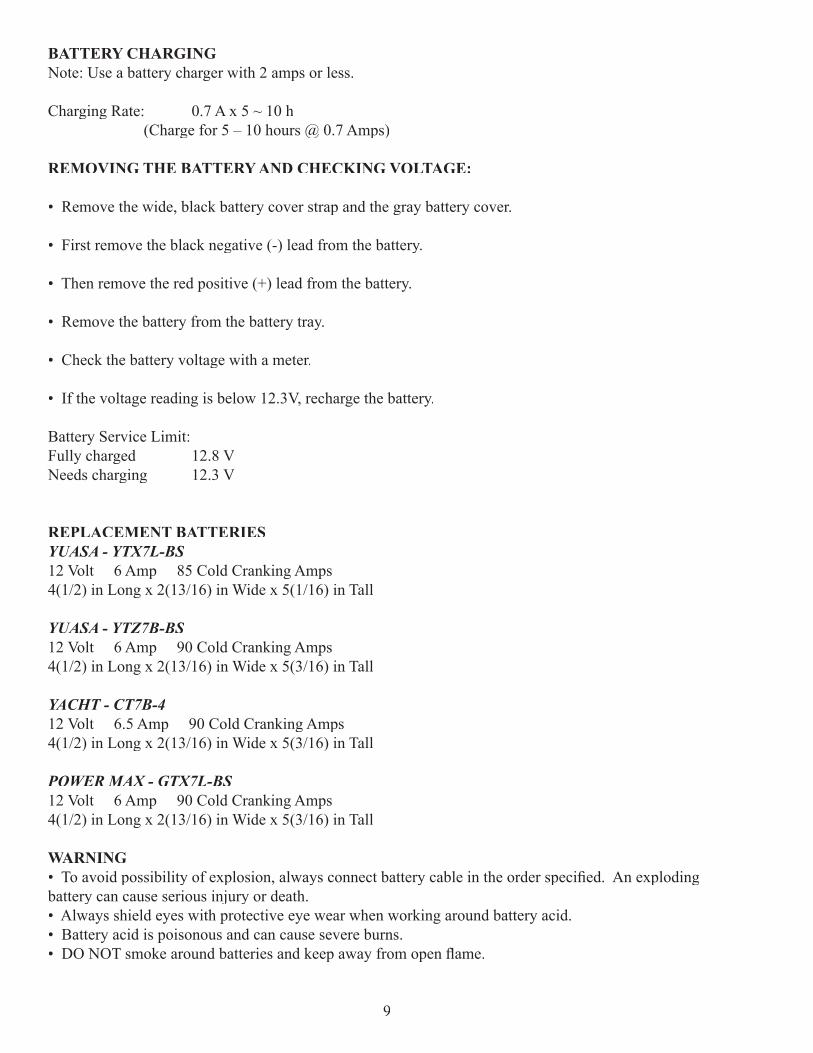
BATTERY CHARGINGNote: Use a battery charger with 2 amps or less.
Charging Rate: 0.7 A x 5 ~ 10 h (Charge for 5 – 10 hours @ 0.7 Amps)
REMOVING THE BATTERY AND CHECKING VOLTAGE:
• Remove the wide, black battery cover strap and the gray battery cover.
• First remove the black negative (-) lead from the battery.
• Then remove the red positive (+) lead from the battery.
• Remove the battery from the battery tray.
• Check the battery voltage with a meter.
• If the voltage reading is below 12.3V, recharge the battery.
Battery Service Limit:Fully charged 12.8 VNeeds charging 12.3 V
REPLACEMENT BATTERIESYUASA - YTX7L-BS12 Volt 6 Amp 85 Cold Cranking Amps4(1/2) in Long x 2(13/16) in Wide x 5(1/16) in Tall
YUASA - YTZ7B-BS12 Volt 6 Amp 90 Cold Cranking Amps4(1/2) in Long x 2(13/16) in Wide x 5(3/16) in Tall
YACHT - CT7B-412 Volt 6.5 Amp 90 Cold Cranking Amps4(1/2) in Long x 2(13/16) in Wide x 5(3/16) in Tall
POWER MAX - GTX7L-BS12 Volt 6 Amp 90 Cold Cranking Amps4(1/2) in Long x 2(13/16) in Wide x 5(3/16) in Tall
WARNING• To avoid possibility of explosion, always connect battery cable in the order specifi ed. An exploding battery can cause serious injury or death.• Always shield eyes with protective eye wear when working around battery acid.• Battery acid is poisonous and can cause severe burns.• DO NOT smoke around batteries and keep away from open fl ame.
9
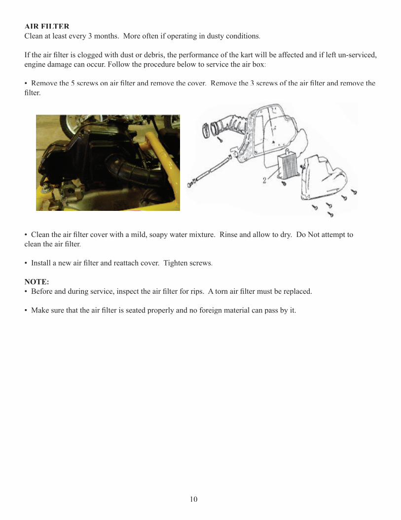
AIR FILTERClean at least every 3 months. More often if operating in dusty conditions.
If the air fi lter is clogged with dust or debris, the performance of the kart will be affected and if left un-serviced, engine damage can occur. Follow the procedure below to service the air box:
• Remove the 5 screws on air fi lter and remove the cover. Remove the 3 screws of the air fi lter and remove the fi lter.
• Clean the air fi lter cover with a mild, soapy water mixture. Rinse and allow to dry. Do Not attempt to clean the air fi lter.
• Install a new air fi lter and reattach cover. Tighten screws.
NOTE:• Before and during service, inspect the air fi lter for rips. A torn air fi lter must be replaced.
• Make sure that the air fi lter is seated properly and no foreign material can pass by it.
10

NUTS AND BOLTSNuts and bolts should be checked to ensure that they are tight before every ride..
Because frequent operation can cause the kart’s nuts and bolts to loosen, they should be checked and tightened often. When tightening nuts/bolts, please reference the chart below.TIGHTENING TORQUE CHART
TablesFASTENERThread Size
TORQUE(ft/lbs/in lbs)
T O R Q U E (Nm)
5 mm bolts and nuts 39-52 in lbs 4.5-6 Nm6mm bolts and nuts 69-104 in lbs 8-12 Nm8mm bolts and nuts 13-18 ft lbs 18-25 Nm
10 mm bolts and nuts 22-29 ft lbs 30-40 Nm12 mm bolts and nuts 36-43 ft lbs 50-60 Nm
4 mm screws 22-30 in lbs 2.5-3.4 Nm5mm screws 30-43 in lbs 3.5-5 Nm
6 mm hex bolts 87-121 in lbs 10-14 Nm8 mm hex bolts 17-22 ft lbs 24-30 Nm10 mm hex bolts 25-32 ft lbs 35-45 Nm
11
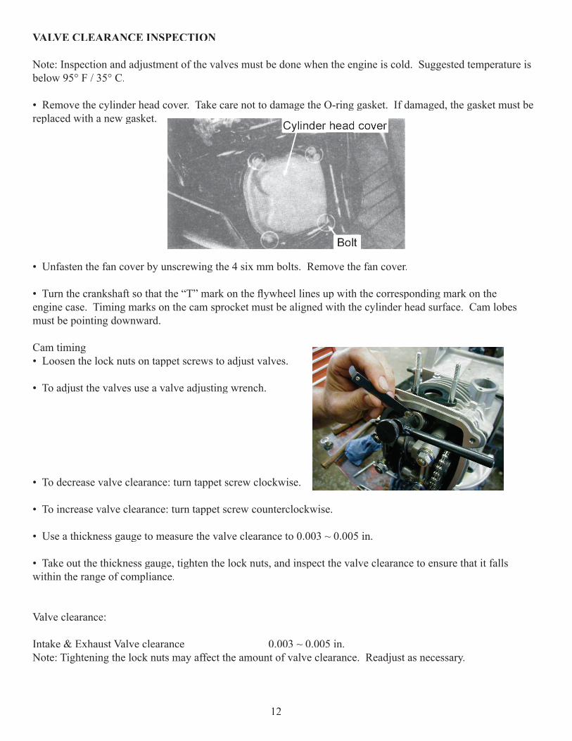
VALVE CLEARANCE INSPECTION
Note: Inspection and adjustment of the valves must be done when the engine is cold. Suggested temperature is below 95° F / 35° C.
• Remove the cylinder head cover. Take care not to damage the O-ring gasket. If damaged, the gasket must be replaced with a new gasket.
• Unfasten the fan cover by unscrewing the 4 six mm bolts. Remove the fan cover.
• Turn the crankshaft so that the “T” mark on the fl ywheel lines up with the corresponding mark on the engine case. Timing marks on the cam sprocket must be aligned with the cylinder head surface. Cam lobes must be pointing downward. Cam timing• Loosen the lock nuts on tappet screws to adjust valves.
• To adjust the valves use a valve adjusting wrench.
• To decrease valve clearance: turn tappet screw clockwise.
• To increase valve clearance: turn tappet screw counterclockwise.
• Use a thickness gauge to measure the valve clearance to 0.003 ~ 0.005 in.
• Take out the thickness gauge, tighten the lock nuts, and inspect the valve clearance to ensure that it falls within the range of compliance.
Valve clearance:
Intake & Exhaust Valve clearance 0.003 ~ 0.005 in.Note: Tightening the lock nuts may affect the amount of valve clearance. Readjust as necessary.
12
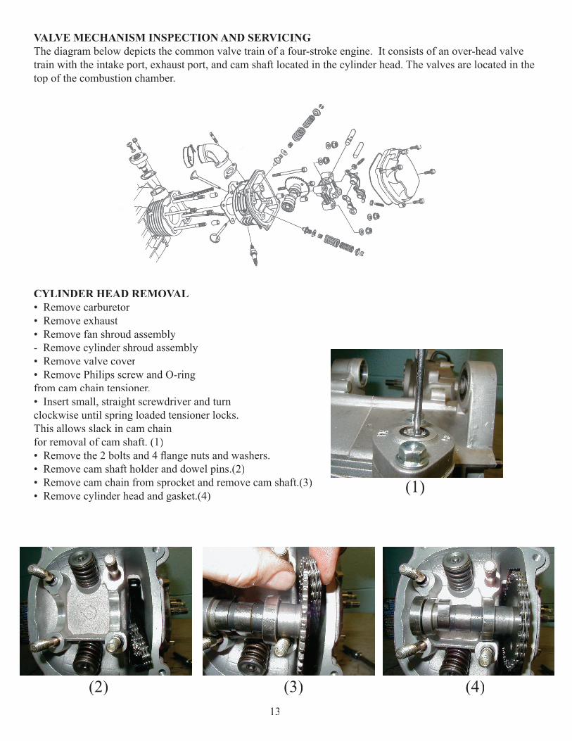
VALVE MECHANISM INSPECTION AND SERVICINGThe diagram below depicts the common valve train of a four-stroke engine. It consists of an over-head valve train with the intake port, exhaust port, and cam shaft located in the cylinder head. The valves are located in the top of the combustion chamber.
CYLINDER HEAD REMOVAL• Remove carburetor• Remove exhaust• Remove fan shroud assembly- Remove cylinder shroud assembly• Remove valve cover• Remove Philips screw and O-ring from cam chain tensioner. • Insert small, straight screwdriver and turn clockwise until spring loaded tensioner locks. This allows slack in cam chain for removal of cam shaft. (1)• Remove the 2 bolts and 4 fl ange nuts and washers.• Remove cam shaft holder and dowel pins.(2)• Remove cam chain from sprocket and remove cam shaft.(3)• Remove cylinder head and gasket.(4) (1)
(2) (3) (4)13
CYLINDER HEAD INSTALLATION• Install new gasket and dowel pins onto cylinder.• Install cam chain guide.• Install cylinder head.
• Align the “T” mark on the fl ywheel with the index mark on the engine case by turning the fl ywheel.
• Position the camshaft gear with cam chain so that timing marks on sprocket align with the cylinder head surface and the large hole is on the top. (The lobes of the camshaft should be pointing downward.)
• Install the dowel pins.
• Install camshaft holder with “EX” pointing towards exhaust.
Note: Apply some oil on the thread part of the camshaft holder bolt.
The camshaft holder nuts should be tightened gradually in 2 ~ 3 times diagonally.After installing, adjust the valve clearance.
• Torque the cylinder head nuts and bolts. Bolts: 95 in. / lbs. Nuts: 16 ft. / lbs.
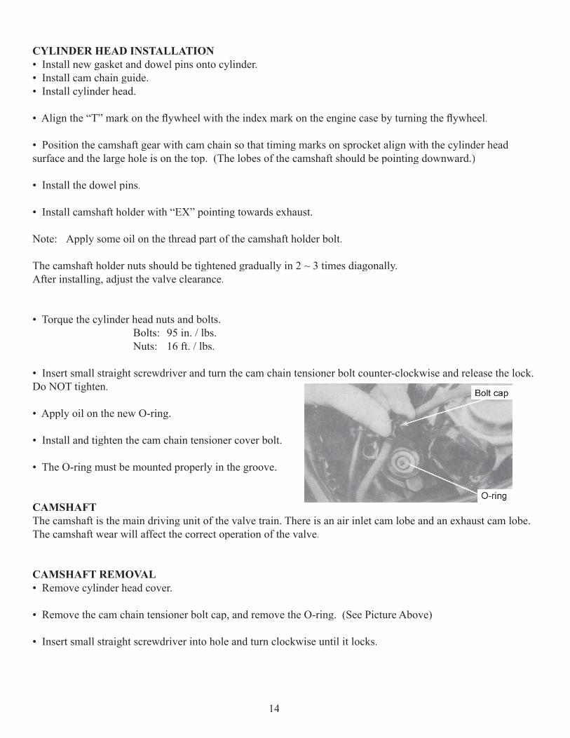
• Insert small straight screwdriver and turn the cam chain tensioner bolt counter-clockwise and release the lock. Do NOT tighten.
• Apply oil on the new O-ring.
• Install and tighten the cam chain tensioner cover bolt.
• The O-ring must be mounted properly in the groove.
CAMSHAFTThe camshaft is the main driving unit of the valve train. There is an air inlet cam lobe and an exhaust cam lobe. The camshaft wear will affect the correct operation of the valve.
CAMSHAFT REMOVAL• Remove cylinder head cover.
• Remove the cam chain tensioner bolt cap, and remove the O-ring. (See Picture Above)
• Insert small straight screwdriver into hole and turn clockwise until it locks.
14
• Turn the fl ywheel counter-clockwise to make the “T” mark on the fl ywheel align with the mark on the crank-case.
• When the hole on the cam chain sprocket is pointing upwards and cam lobes are pointing down, it is at top dead center position.
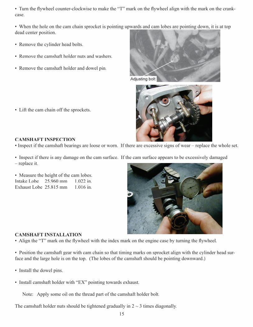
• Remove the cylinder head bolts.
• Remove the camshaft holder nuts and washers.
• Remove the camshaft holder and dowel pin.
• Lift the cam chain off the sprockets.
CAMSHAFT INSPECTION• Inspect if the camshaft bearings are loose or worn. If there are excessive signs of wear – replace the whole set.
• Inspect if there is any damage on the cam surface. If the cam surface appears to be excessively damaged – replace it.
• Measure the height of the cam lobes. Intake Lobe 25.960 mm 1.022 in.Exhaust Lobe 25.815 mm 1.016 in.
CAMSHAFT INSTALLATION• Align the “T” mark on the fl ywheel with the index mark on the engine case by turning the fl ywheel.
• Position the camshaft gear with cam chain so that timing marks on sprocket align with the cylinder head sur-face and the large hole is on the top. (The lobes of the camshaft should be pointing downward.)
• Install the dowel pins.
• Install camshaft holder with “EX” pointing towards exhaust.
Note: Apply some oil on the thread part of the camshaft holder bolt.
The camshaft holder nuts should be tightened gradually in 2 ~ 3 times diagonally.15
After installing, adjust the valve clearance.
• Torque the cylinder head nuts and bolts. Bolts: 95 in. / lbs. Nuts: 16 ft. / lbs.
• Insert small straight screwdriver and turn the cam chain tensioner bolt counter-clockwise and release the lock. Do NOT tighten.
• Apply oil on the new O-ring.
• Install and tighten the cam chain tensioner cover bolt.
• The O-ring must be mounted properly in the groove.
16
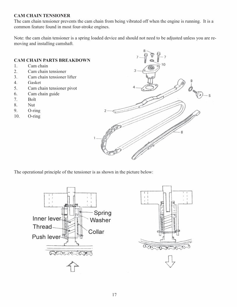
CAM CHAIN TENSIONERThe cam chain tensioner prevents the cam chain from being vibrated off when the engine is running. It is a common feature found in most four-stroke engines.
Note: the cam chain tensioner is a spring loaded device and should not need to be adjusted unless you are re-moving and installing camshaft.
CAM CHAIN PARTS BREAKDOWN 1. Cam chain2. Cam chain tensioner3. Cam chain tensioner lifter4. Gasket5. Cam chain tensioner pivot6. Cam chain guide7. Bolt8. Nut9. O-ring10. O-ring
The operational principle of the tensioner is as shown in the picture below:
17
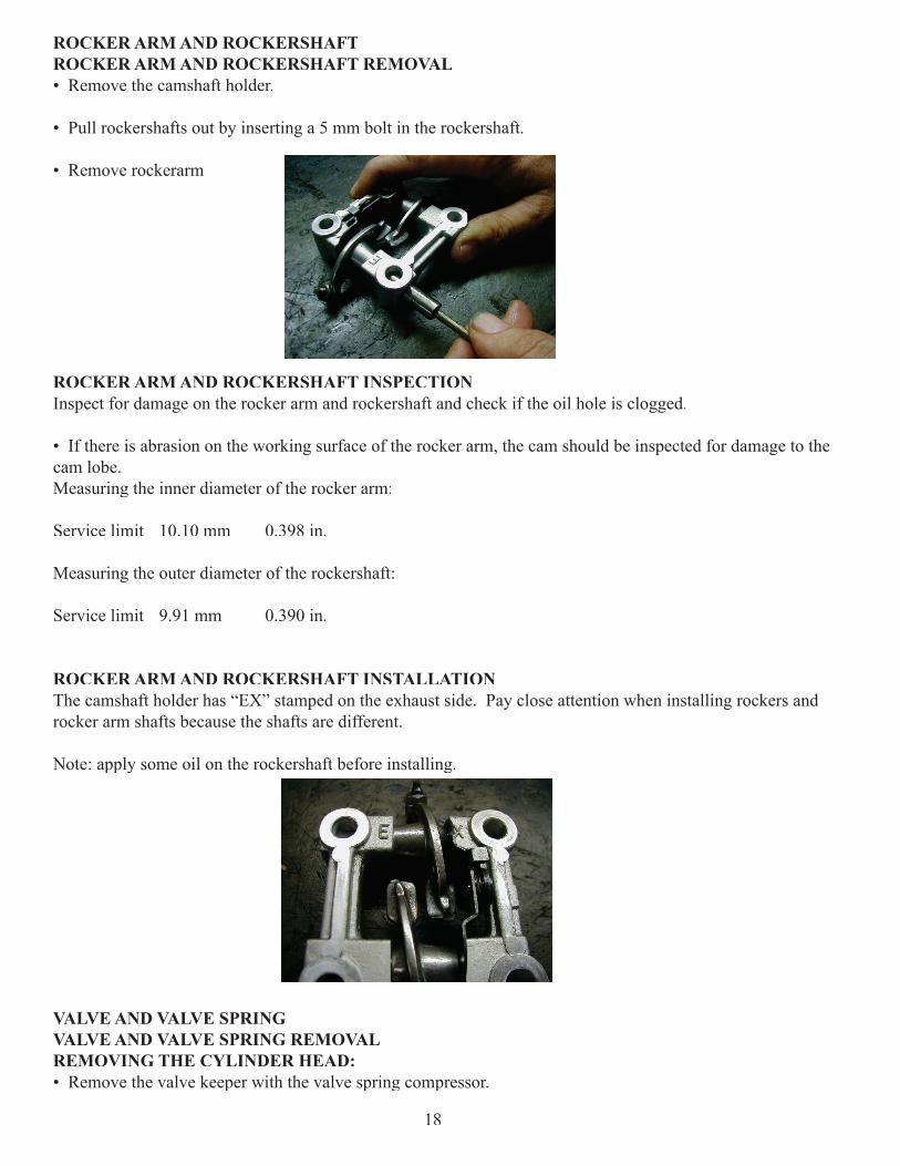
ROCKER ARM AND ROCKERSHAFTROCKER ARM AND ROCKERSHAFT REMOVAL• Remove the camshaft holder.
• Pull rockershafts out by inserting a 5 mm bolt in the rockershaft.
• Remove rockerarm
ROCKER ARM AND ROCKERSHAFT INSPECTIONInspect for damage on the rocker arm and rockershaft and check if the oil hole is clogged.
• If there is abrasion on the working surface of the rocker arm, the cam should be inspected for damage to the cam lobe.Measuring the inner diameter of the rocker arm:
Service limit 10.10 mm 0.398 in.
Measuring the outer diameter of the rockershaft:
Service limit 9.91 mm 0.390 in.
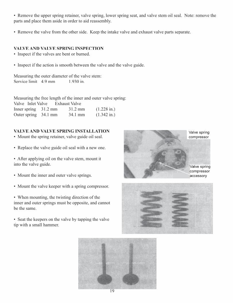
ROCKER ARM AND ROCKERSHAFT INSTALLATIONThe camshaft holder has “EX” stamped on the exhaust side. Pay close attention when installing rockers and rocker arm shafts because the shafts are different.
Note: apply some oil on the rockershaft before installing.
VALVE AND VALVE SPRINGVALVE AND VALVE SPRING REMOVALREMOVING THE CYLINDER HEAD:• Remove the valve keeper with the valve spring compressor.
18
• Remove the upper spring retainer, valve spring, lower spring seat, and valve stem oil seal. Note: remove the parts and place them aside in order to aid reassembly.
• Remove the valve from the other side. Keep the intake valve and exhaust valve parts separate.
VALVE AND VALVE SPRING INSPECTION• Inspect if the valves are bent or burned.
• Inspect if the action is smooth between the valve and the valve guide.
Measuring the outer diameter of the valve stem:Service limit 4.9 mm 1.930 in.
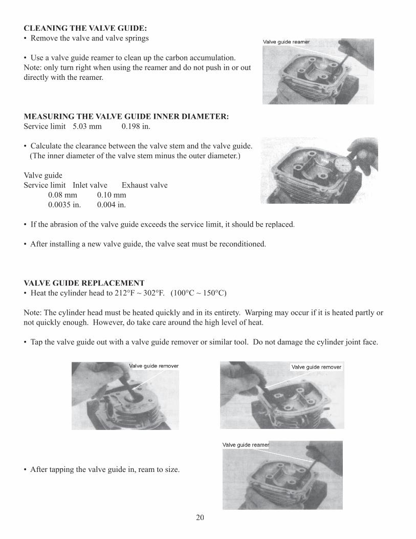
Measuring the free length of the inner and outer valve spring:Valve Inlet Valve Exhaust Valve Inner spring 31.2 mm 31.2 mm (1.228 in.)Outer spring 34.1 mm 34.1 mm (1.342 in.)
VALVE AND VALVE SPRING INSTALLATION• Mount the spring retainer, valve guide oil seal.
• Replace the valve guide oil seal with a new one.
• After applying oil on the valve stem, mount it into the valve guide.
• Mount the inner and outer valve springs.
• Mount the valve keeper with a spring compressor. 3-1-91
• When mounting, the twisting direction of the inner and outer springs must be opposite, and cannot be the same.
• Seat the keepers on the valve by tapping the valve tip with a small hammer.
19
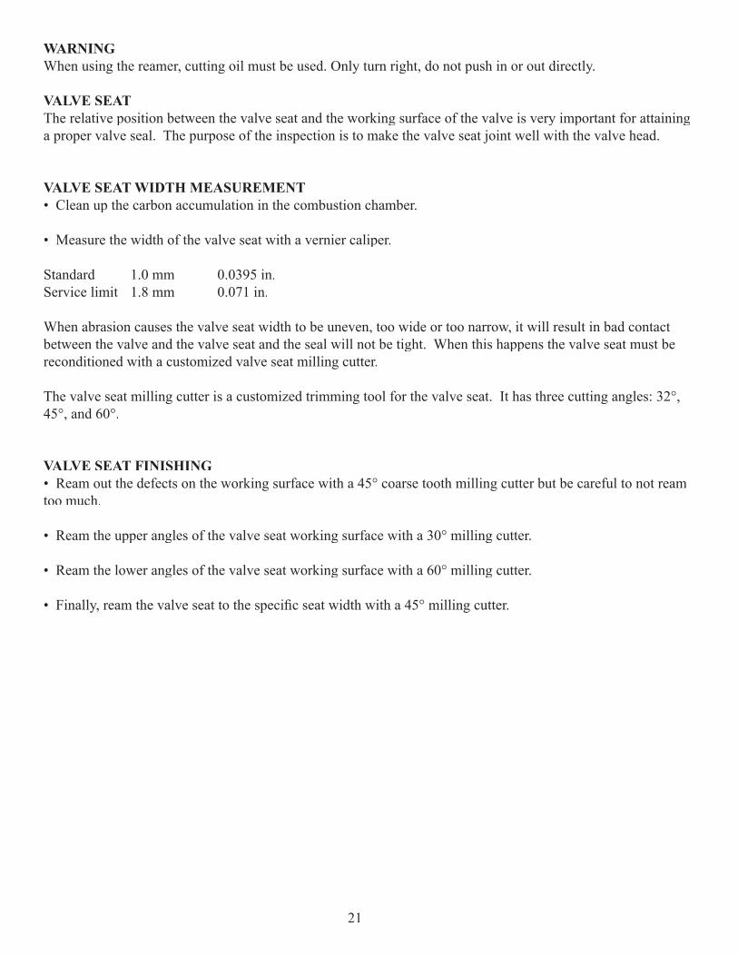
CLEANING THE VALVE GUIDE:• Remove the valve and valve springs
• Use a valve guide reamer to clean up the carbon accumulation. Note: only turn right when using the reamer and do not push in or out directly with the reamer.
MEASURING THE VALVE GUIDE INNER DIAMETER:Service limit 5.03 mm 0.198 in.
• Calculate the clearance between the valve stem and the valve guide. (The inner diameter of the valve stem minus the outer diameter.)
Valve guideService limit Inlet valve Exhaust valve 0.08 mm 0.10 mm 0.0035 in. 0.004 in.
• If the abrasion of the valve guide exceeds the service limit, it should be replaced.
• After installing a new valve guide, the valve seat must be reconditioned.
VALVE GUIDE REPLACEMENT• Heat the cylinder head to 212°F ~ 302°F. (100°C ~ 150°C)
Note: The cylinder head must be heated quickly and in its entirety. Warping may occur if it is heated partly or not quickly enough. However, do take care around the high level of heat.
• Tap the valve guide out with a valve guide remover or similar tool. Do not damage the cylinder joint face.
• After tapping the valve guide in, ream to size.
20
WARNING When using the reamer, cutting oil must be used. Only turn right, do not push in or out directly.
VALVE SEATThe relative position between the valve seat and the working surface of the valve is very important for attaining a proper valve seal. The purpose of the inspection is to make the valve seat joint well with the valve head.
VALVE SEAT WIDTH MEASUREMENT• Clean up the carbon accumulation in the combustion chamber.
• Measure the width of the valve seat with a vernier caliper.
Standard 1.0 mm 0.0395 in.Service limit 1.8 mm 0.071 in.
When abrasion causes the valve seat width to be uneven, too wide or too narrow, it will result in bad contact between the valve and the valve seat and the seal will not be tight. When this happens the valve seat must be reconditioned with a customized valve seat milling cutter.
The valve seat milling cutter is a customized trimming tool for the valve seat. It has three cutting angles: 32°, 45°, and 60°.
VALVE SEAT FINISHING• Ream out the defects on the working surface with a 45° coarse tooth milling cutter but be careful to not ream too much.
• Ream the upper angles of the valve seat working surface with a 30° milling cutter.
• Ream the lower angles of the valve seat working surface with a 60° milling cutter.
• Finally, ream the valve seat to the specifi c seat width with a 45° milling cutter.
21
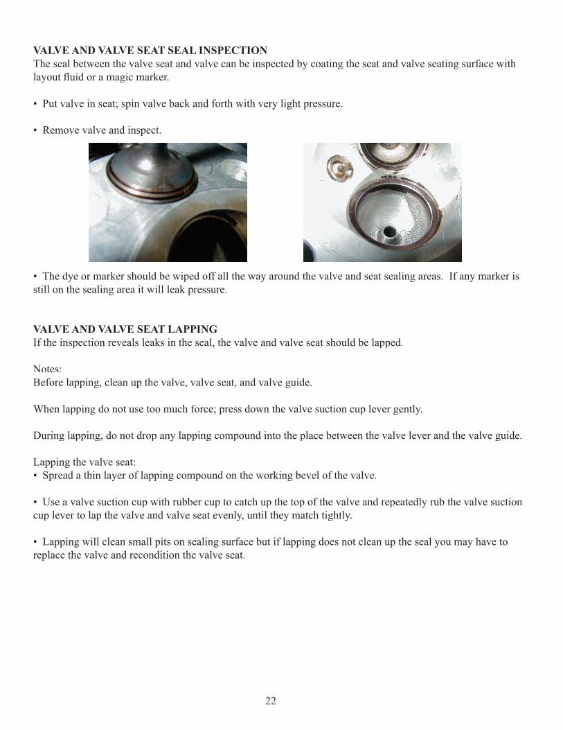
VALVE AND VALVE SEAT SEAL INSPECTIONThe seal between the valve seat and valve can be inspected by coating the seat and valve seating surface with layout fl uid or a magic marker.
• Put valve in seat; spin valve back and forth with very light pressure.
• Remove valve and inspect.
• The dye or marker should be wiped off all the way around the valve and seat sealing areas. If any marker is still on the sealing area it will leak pressure.
VALVE AND VALVE SEAT LAPPINGIf the inspection reveals leaks in the seal, the valve and valve seat should be lapped.
Notes:Before lapping, clean up the valve, valve seat, and valve guide.
When lapping do not use too much force; press down the valve suction cup lever gently.
During lapping, do not drop any lapping compound into the place between the valve lever and the valve guide.
Lapping the valve seat:• Spread a thin layer of lapping compound on the working bevel of the valve.
• Use a valve suction cup with rubber cup to catch up the top of the valve and repeatedly rub the valve suction cup lever to lap the valve and valve seat evenly, until they match tightly.
• Lapping will clean small pits on sealing surface but if lapping does not clean up the seal you may have to replace the valve and recondition the valve seat.
22
ENGINE COMPONENTS INSPECTION AND SERVICINGINSPECTION AND SERVICING: ENGINE COMPONENTS AND CRANK CONNECTING ROD MECHANISM
CYLINDERCYLINDER REMOVAL:• Remove cylinder head (See Cylinder Head Removal under Valve Mechanism Inspection).
• Remove cylinder
• Clean gasket surface
CYLINDER BORE INSPECTION:• Remove all gasket material from the cylinder sealing surfaces.
• Inspect the top of the cylinder for evidence of warping using a straight edge and feeler gauge.
Service Limit 0.04 mm 0.002 in.
• Inspect cylinder for wear, scratches, or damage.
• Inspect cylinder for taper and out of round. Measure in two different directions, front-to-back and side-to-side, on three different levels:
1. 1/2” down from top2. in the middle 3. 1/2” up from bottom
• Record measurements. If cylinder is tapered or out of round beyond 0.04 mm or 0.002 in., the cylinder must be replaced.
CYLINDER BORE Service Limit 52.05 mm 2.049 in.Cylinder Taper 0.05 mm 0.002 in.Cylinder Out of Round 0.05 mm 0.002 in.
23
PISTON SETPISTON PIN INSPECTION AND SERVICING:• Insert the piston pin horizontally into the piston pin hole, and inspect the clearance between piston and piston pin.
Service limit 0.02 mm 0.001 in.
MEASURING THE EXTERNAL DIAMETER OF PISTON PIN:• If the measurement is less than the service limit, the piston pin should be replaced.Service limit 14.96 mm 0.589 in.
• After replacement, the clearance between piston pin and piston pin hole should be checked again to ensure compliance with the proper diameter.
MEASURING THE INNER DIAMETER OF PISTON PIN HOLE: Service limit 15.04 mm 0.5925 in.
• If the result is more than the service limit, replace the piston.
INSPECTION AND SERVICING PISTON RINGS:• Measure piston ring-to-groove clearance by placing the ring in the ring core and measuring with a thickness gauge.
• Replace piston and rings if ring-to-groove clearance exceeds service limits.
First Ring Service limit 0.09 mm 0.0035 in.
Second RingService limit 0.09 mm 0.0035 in.
Oil RingService limit 0.12 mm .0045 in.
24
CONNECTING ROD END INSPECTION:• Measure the inner diameter of the connecting rod at the small end. Service limit 15.06mm 0.593 in.
• If the connecting rod is damaged beyond the service limit, the crankshaft should be replaced.
PISTON RING INSTALLATION GAP:• Apply oil on every piston ring.
• Enlarge piston rings, while placing them on the piston and move downwards gradually, until piston rings fall into ring groove.
PISTON INSTALLATION• Mount piston onto the small end of the connecting rod.
• Apply oil on the piston pin to lubricate it.
• Place a piece of cloth on the crank case port to prevent the piston pin clip from dropping into the crankcase.
25
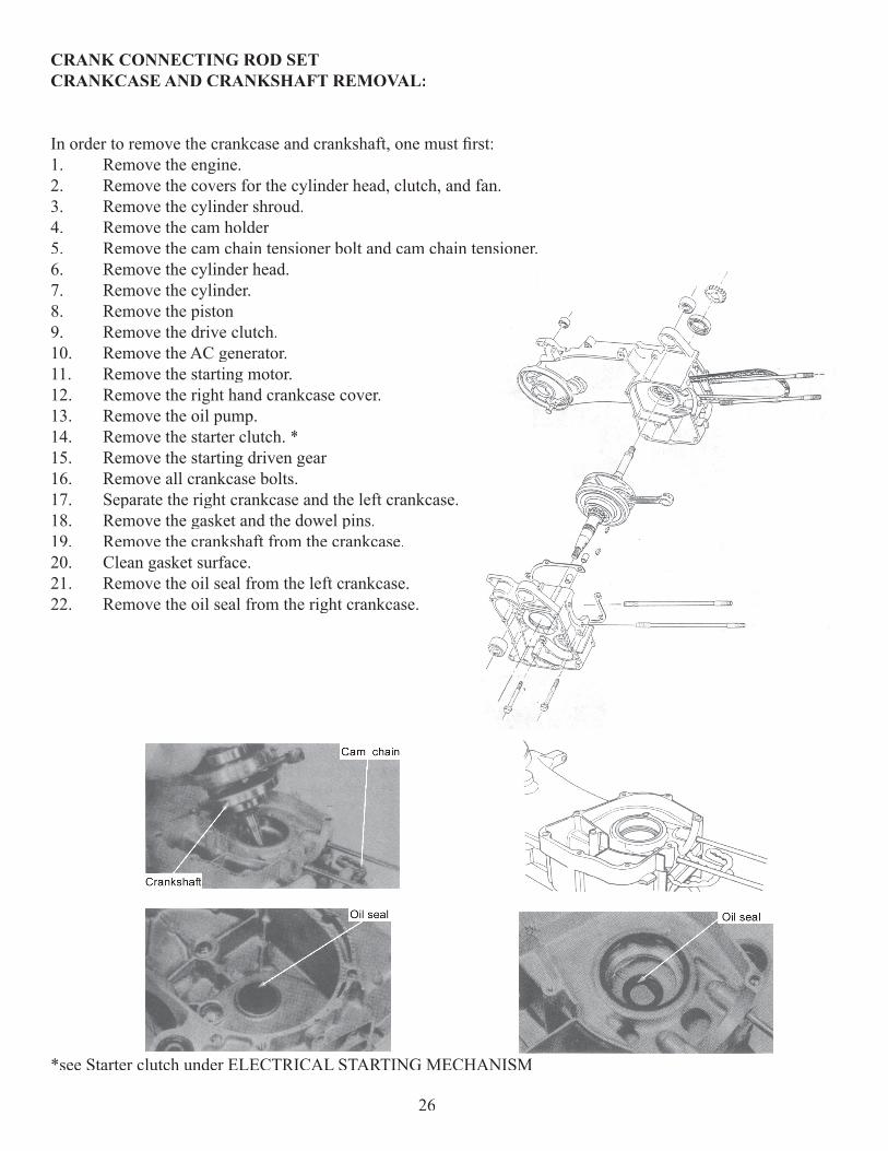
CRANK CONNECTING ROD SETCRANKCASE AND CRANKSHAFT REMOVAL:
In order to remove the crankcase and crankshaft, one must fi rst:1. Remove the engine.2. Remove the covers for the cylinder head, clutch, and fan.3. Remove the cylinder shroud.4. Remove the cam holder5. Remove the cam chain tensioner bolt and cam chain tensioner.6. Remove the cylinder head.7. Remove the cylinder.8. Remove the piston9. Remove the drive clutch.10. Remove the AC generator.11. Remove the starting motor.12. Remove the right hand crankcase cover.13. Remove the oil pump.14. Remove the starter clutch. *15. Remove the starting driven gear16. Remove all crankcase bolts.17. Separate the right crankcase and the left crankcase.18. Remove the gasket and the dowel pins.19. Remove the crankshaft from the crankcase.20. Clean gasket surface.21. Remove the oil seal from the left crankcase. 22. Remove the oil seal from the right crankcase.
*see Starter clutch under ELECTRICAL STARTING MECHANISM
26
CRANKSHAFT INSPECTION
CONNECTING ROD SIDE CLEARANCE:• Measure connecting rod big end side clearance with a feeler gauge. • Compare to specifi cations.• If the clearance is greater than service limit the crankshaft assembly must be replaced.
Service limit 0.55 mm 0.022 in.
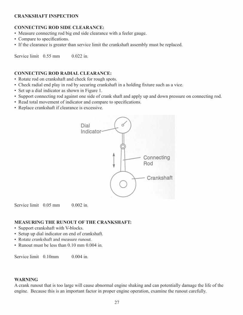
CONNECTING ROD RADIAL CLEARANCE:• Rotate rod on crankshaft and check for rough spots. • Check radial end play in rod by securing crankshaft in a holding fi xture such as a vice. • Set up a dial indicator as shown in Figure 1.• Support connecting rod against one side of crank shaft and apply up and down pressure on connecting rod. • Read total movement of indicator and compare to specifi cations. • Replace crankshaft if clearance is excessive.
Service limit 0.05 mm 0.002 in.
MEASURING THE RUNOUT OF THE CRANKSHAFT:• Support crankshaft with V-blocks. • Setup up dial indicator on end of crankshaft.• Rotate crankshaft and measure runout. • Runout must be less than 0.10 mm 0.004 in.
Service limit 0.10mm 0.004 in.
WARNING A crank runout that is too large will cause abnormal engine shaking and can potentially damage the life of the engine. Because this is an important factor in proper engine operation, examine the runout carefully.
27
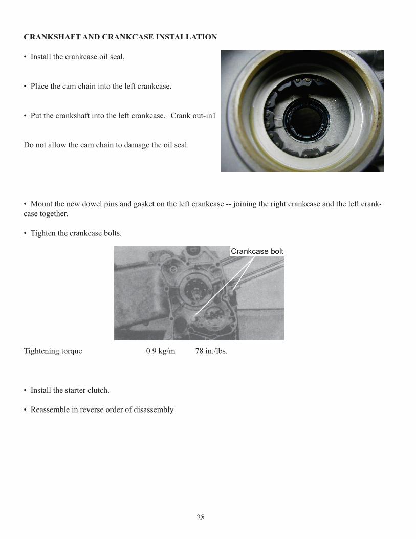
CRANKSHAFT AND CRANKCASE INSTALLATION
• Install the crankcase oil seal.
• Place the cam chain into the left crankcase.
• Put the crankshaft into the left crankcase. Crank out-in1
Do not allow the cam chain to damage the oil seal.
• Mount the new dowel pins and gasket on the left crankcase -- joining the right crankcase and the left crank-case together.
• Tighten the crankcase bolts.
Tightening torque 0.9 kg/m 78 in./lbs.
• Install the starter clutch.
• Reassemble in reverse order of disassembly.
28
LUBRICATION SYSTEM INSPECTION AND SERVICING
Explanation of lubrication system process:
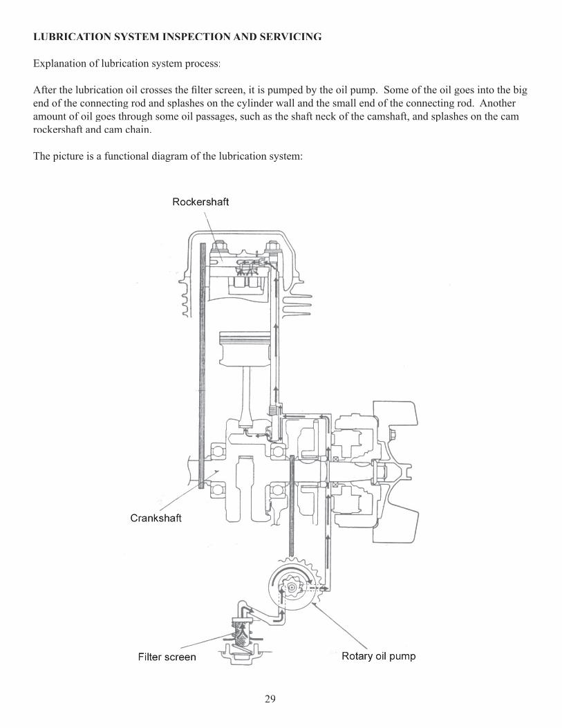
After the lubrication oil crosses the fi lter screen, it is pumped by the oil pump. Some of the oil goes into the big end of the connecting rod and splashes on the cylinder wall and the small end of the connecting rod. Another amount of oil goes through some oil passages, such as the shaft neck of the camshaft, and splashes on the cam rockershaft and cam chain.
The picture is a functional diagram of the lubrication system:
29
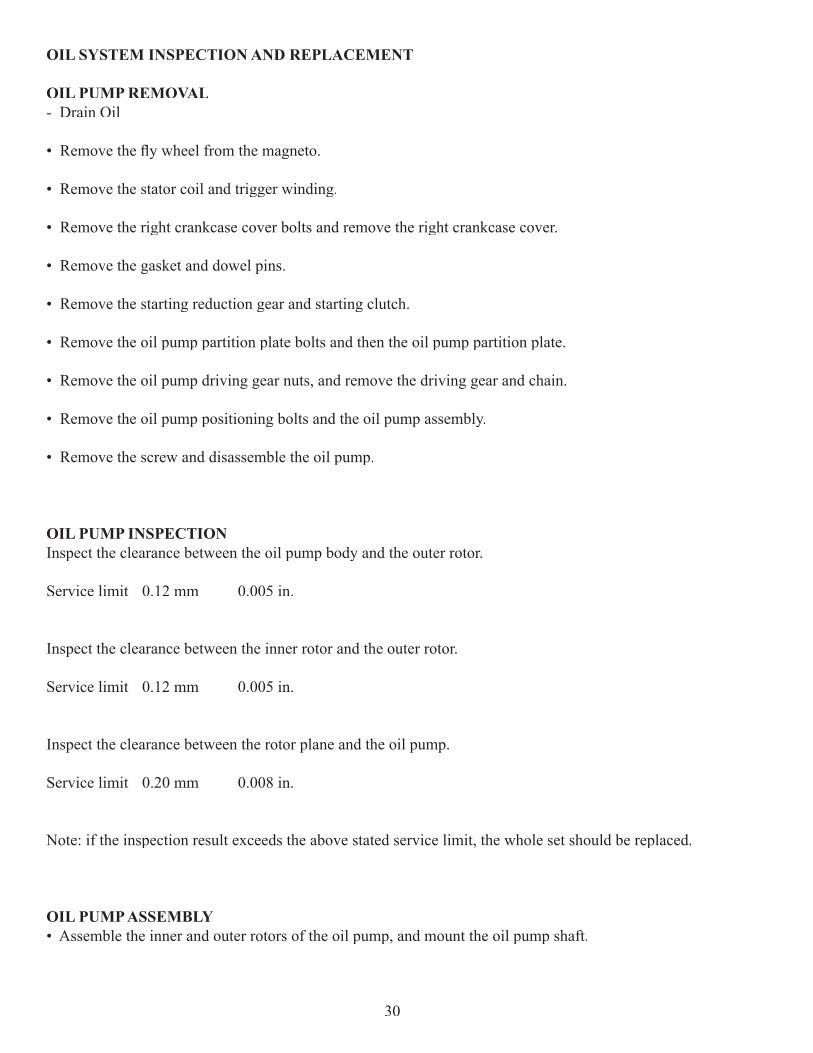
OIL SYSTEM INSPECTION AND REPLACEMENT
OIL PUMP REMOVAL- Drain Oil
• Remove the fl y wheel from the magneto.
• Remove the stator coil and trigger winding.
• Remove the right crankcase cover bolts and remove the right crankcase cover.
• Remove the gasket and dowel pins.
• Remove the starting reduction gear and starting clutch.
• Remove the oil pump partition plate bolts and then the oil pump partition plate.
• Remove the oil pump driving gear nuts, and remove the driving gear and chain.
• Remove the oil pump positioning bolts and the oil pump assembly.
• Remove the screw and disassemble the oil pump.
OIL PUMP INSPECTIONInspect the clearance between the oil pump body and the outer rotor.
Service limit 0.12 mm 0.005 in.
Inspect the clearance between the inner rotor and the outer rotor.
Service limit 0.12 mm 0.005 in.
Inspect the clearance between the rotor plane and the oil pump.
Service limit 0.20 mm 0.008 in.
Note: if the inspection result exceeds the above stated service limit, the whole set should be replaced.
OIL PUMP ASSEMBLY• Assemble the inner and outer rotors of the oil pump, and mount the oil pump shaft.
30
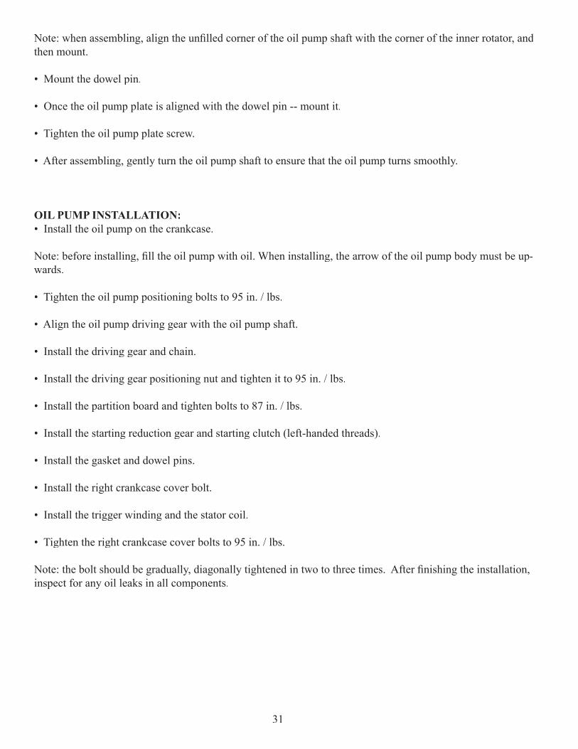
Note: when assembling, align the unfi lled corner of the oil pump shaft with the corner of the inner rotator, and then mount.
• Mount the dowel pin.
• Once the oil pump plate is aligned with the dowel pin -- mount it.
• Tighten the oil pump plate screw.
• After assembling, gently turn the oil pump shaft to ensure that the oil pump turns smoothly.
OIL PUMP INSTALLATION:• Install the oil pump on the crankcase.
Note: before installing, fi ll the oil pump with oil. When installing, the arrow of the oil pump body must be up-wards.
• Tighten the oil pump positioning bolts to 95 in. / lbs.
• Align the oil pump driving gear with the oil pump shaft.
• Install the driving gear and chain.
• Install the driving gear positioning nut and tighten it to 95 in. / lbs.
• Install the partition board and tighten bolts to 87 in. / lbs.
• Install the starting reduction gear and starting clutch (left-handed threads).
• Install the gasket and dowel pins.
• Install the right crankcase cover bolt.
• Install the trigger winding and the stator coil.
• Tighten the right crankcase cover bolts to 95 in. / lbs.
Note: the bolt should be gradually, diagonally tightened in two to three times. After fi nishing the installation, inspect for any oil leaks in all components.
31
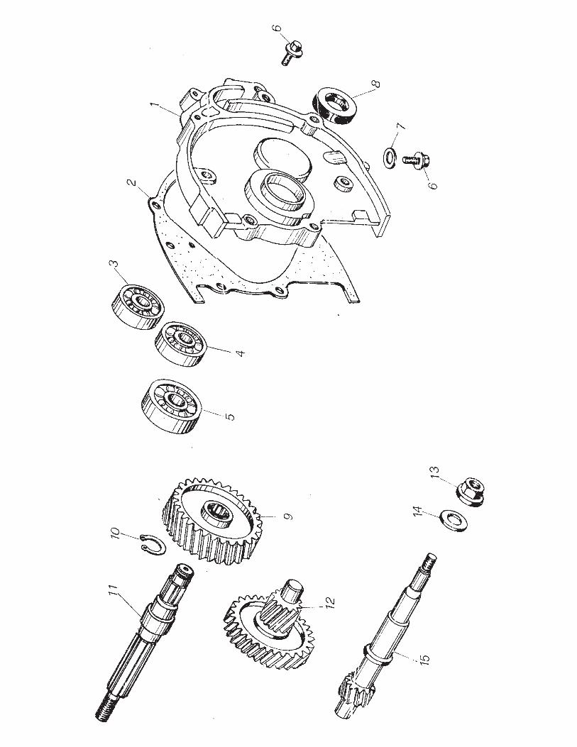
REAR TRANSMISSION MECHANISM INSPECTION AND SERVICING
The structure of the rear transmission mechanism is shown in the picture on the previous page.1. Cover Transmission2. Gasket Transmission Cover3. Radial Ball Bearing 4. Radial Ball Bearing 5. Radial Ball Bearing6. Fill and Drain Plug 7. Sealing Washer 8. Oil Seal 9. Final Gear10. External Circlip 11. Output Shaft12. Counter Shaft13. Nut14. Washer15. Input Shaft
TRANSMISSION CASE OIL INSPECTIONNote: Use a level surface when inspecting the oil level of the transmission case.
• Inspect if there is oil leaking around the transmission case.
• After the engine stops, remove the transmission case oil viewing bolt.
• Observe the oil level when the oil level is parallel with the observing hole.
• When the oil level is too low, use the appropriate oil and add until oil fl ows from the level screw.
• Mount the transmission case oil viewing bolt and washer.
• Assure that the bolt oil seal is undamaged.
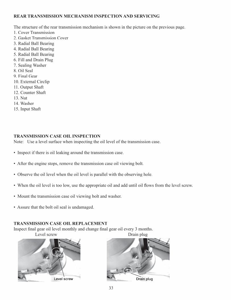
TRANSMISSION CASE OIL REPLACEMENTInspect fi nal gear oil level monthly and change fi nal gear oil every 3 months. Level screw Drain plug
33
• To check level, remove level screw on the left rear engine case. If gear oil does not come out of hole, add until it does.
• To drain gear oil, remove the drain plug at the rear bottom of the engine case. It is recommended to warm the engine for 10 minutes or more before draining fi nal gear oil.
Note:API Service Standard GL-5, GL-4, GL-3 SAE 80W 90 gear oil is recommended in the fi nal drive case. How-ever, in extreme cold weather conditions it is then advised to use lighter viscosity oil, such as 75 wt. Final drive capacity: 115 cc 4 oz.
TRANSMISSION CASETRANSMISSION CASE REMOVAL
• Remove the driven belt pulley.
• Drain the oil from the transmission case.
• Remove the drive sprocket.
• Remove the bolts and remove the transmission case cover.
• Remove the gasket and dowel pin.
• Remove the fi nal gear from the output shaft, and remove the counter shaft.
TRANSMISSION CASE GEAR INSPECTION
• Inspect the counter shaft gear for damage.
• Inspect the fi nal gear and the output shaft for damage.
TRANSMISSION CASE COVER BEARING REPLACEMENT
• Press the driven belt pulley shaft to make it separate with the transmission cover.
• Remove the oil seal and drive out the bearing.
34
• Remove the fi nal gear shaft bearing.
• Remove the sub shaft bearing.
• Drive in the new fi nal gear shaft and bearing.
Note: When driving in the fi nal gear shaft bearing, keep the bearing parallel. Do the same and keep the bearing parallel when installing the sub shaft bearing and the driven pulley shaft bearing.
• Drive in the new sub shaft bearing.
• Drive in the driven pulley shaft bearing.
LEFT CRANKCASE BODY BEARING REPLACEMENT• Replace the bearing and oil seal on the left crankcase if it is worn or damaged.
• Remove the oil seal.
• Drive out the fi nal gear shaft bearing.
• Remove the sub shaft bearing.
• Remove the driven belt pulley shaft bearing.
• Drive in the new driven belt pulley shaft bearing.
• Drive in the new sub shaft bearing.
• Drive in the new fi nal gear shaft bearing.
• Install the driven belt pulley shaft on the transmission case cover.
• Drive in the transmission case cover oil seal.
• Install the sub shaft/sub shaft gear and the fi nal gear shaft into the left crankcase.
• Mount the fi nal gear on the fi nal gear shaft.
• Install the new dowel pin and gasket.
• Install the transmission case cover and torque bolt to 85in. / lbs.
• Mount the driven pulley / clutch set.
35

• Mount the drive pulley, the transmission belt, and the left crankcase cover.
• Add 80W-90 gear oil in the transmission case until it gets to the proper level.
Gear Oil Amount: 115 cc ml 4 oz.
36
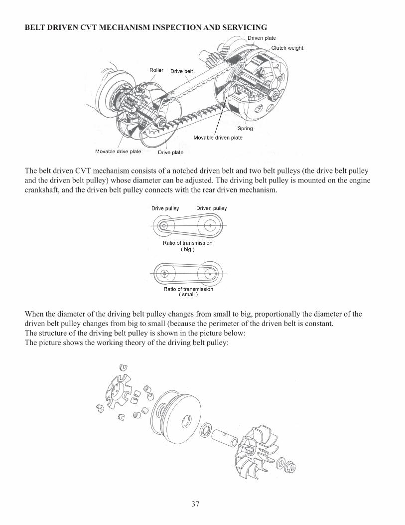
BELT DRIVEN CVT MECHANISM INSPECTION AND SERVICING
The belt driven CVT mechanism consists of a notched driven belt and two belt pulleys (the drive belt pulley and the driven belt pulley) whose diameter can be adjusted. The driving belt pulley is mounted on the engine crankshaft, and the driven belt pulley connects with the rear driven mechanism.
When the diameter of the driving belt pulley changes from small to big, proportionally the diameter of the driven belt pulley changes from big to small (because the perimeter of the driven belt is constant.The structure of the driving belt pulley is shown in the picture below:The picture shows the working theory of the driving belt pulley:
37
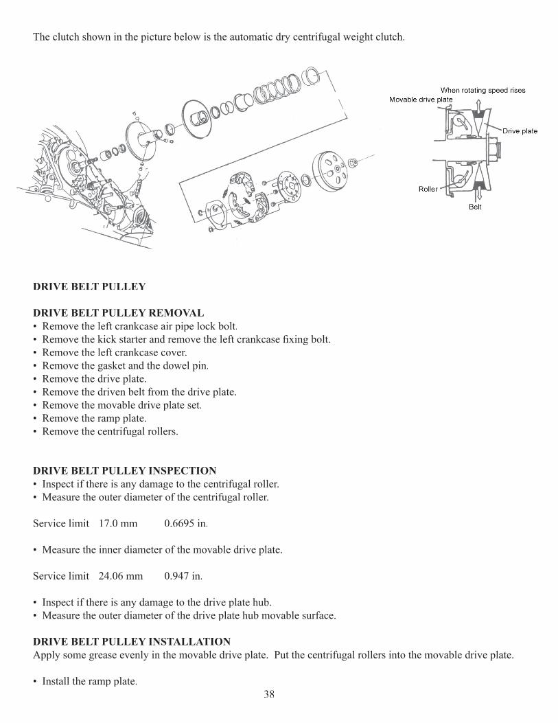
The clutch shown in the picture below is the automatic dry centrifugal weight clutch.
DRIVE BELT PULLEY
DRIVE BELT PULLEY REMOVAL• Remove the left crankcase air pipe lock bolt.• Remove the kick starter and remove the left crankcase fi xing bolt. • Remove the left crankcase cover. • Remove the gasket and the dowel pin.• Remove the drive plate.• Remove the driven belt from the drive plate.• Remove the movable drive plate set.• Remove the ramp plate.• Remove the centrifugal rollers.
DRIVE BELT PULLEY INSPECTION• Inspect if there is any damage to the centrifugal roller.• Measure the outer diameter of the centrifugal roller.
Service limit 17.0 mm 0.6695 in.
• Measure the inner diameter of the movable drive plate.
Service limit 24.06 mm 0.947 in.
• Inspect if there is any damage to the drive plate hub.• Measure the outer diameter of the drive plate hub movable surface.
DRIVE BELT PULLEY INSTALLATIONApply some grease evenly in the movable drive plate. Put the centrifugal rollers into the movable drive plate.
• Install the ramp plate.38
• Put the drive plate hub into the drive plate.
• Install the movable drive plate on the crankshaft.
• Enlarge the driven plate belt groove, and mount on the driven belt. Mount the other end of the driven belt on the drive plate hub.
• Mount the drive plate, the drive plate washer, and nut.
• Torque nut to 40 ft. / lbs.
CLUTCH
CLUTCH REMOVAL• Remove the left crankcase cover.
• Remove the drive plate and the driven belt.
• Remove the clutch drum plate.
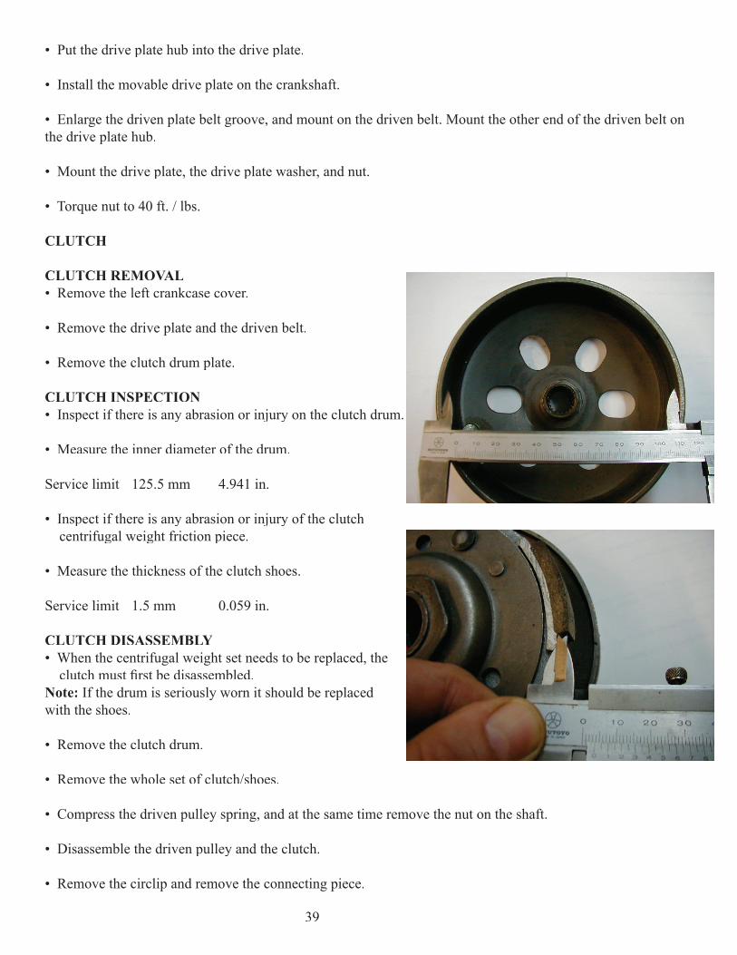
CLUTCH INSPECTION• Inspect if there is any abrasion or injury on the clutch drum.
• Measure the inner diameter of the drum.
Service limit 125.5 mm 4.941 in.
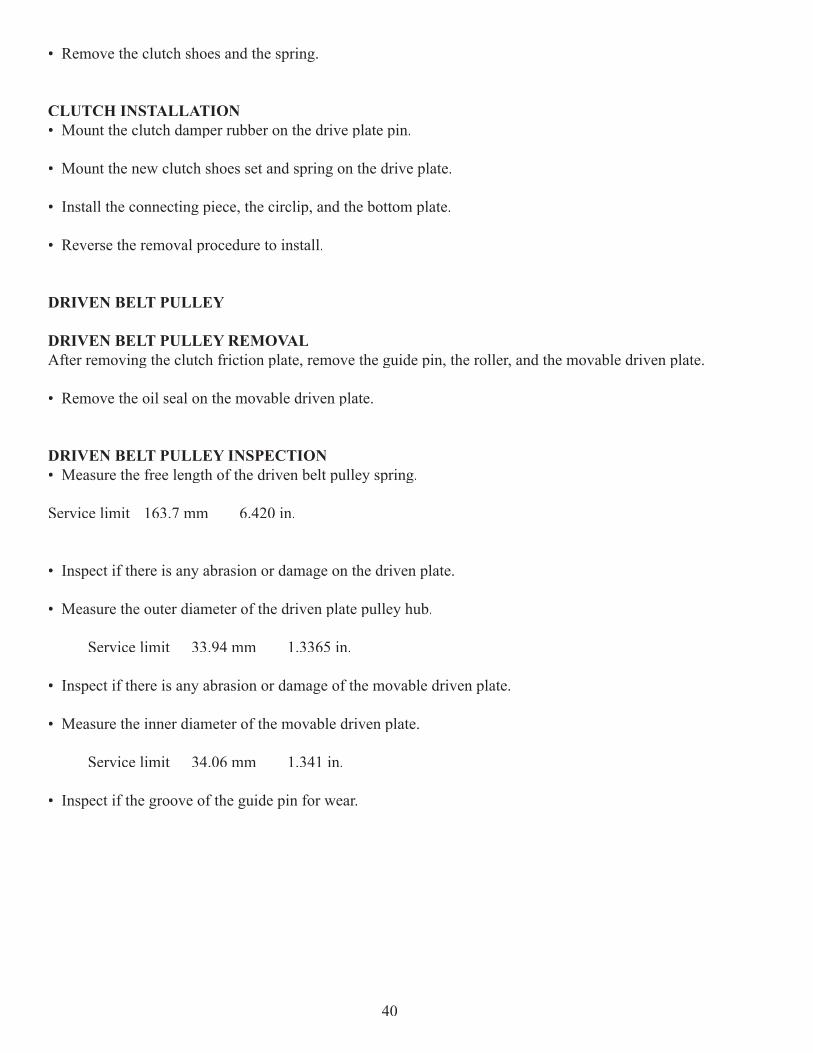
• Inspect if there is any abrasion or injury of the clutch centrifugal weight friction piece.
• Measure the thickness of the clutch shoes.
Service limit 1.5 mm 0.059 in.
CLUTCH DISASSEMBLY• When the centrifugal weight set needs to be replaced, the clutch must fi rst be disassembled.Note: If the drum is seriously worn it should be replaced with the shoes.
• Remove the clutch drum.
• Remove the whole set of clutch/shoes.
• Compress the driven pulley spring, and at the same time remove the nut on the shaft.
• Disassemble the driven pulley and the clutch.
• Remove the circlip and remove the connecting piece.
39
• Remove the clutch shoes and the spring.
CLUTCH INSTALLATION• Mount the clutch damper rubber on the drive plate pin.
• Mount the new clutch shoes set and spring on the drive plate.
• Install the connecting piece, the circlip, and the bottom plate.
• Reverse the removal procedure to install.
DRIVEN BELT PULLEY
DRIVEN BELT PULLEY REMOVALAfter removing the clutch friction plate, remove the guide pin, the roller, and the movable driven plate.
• Remove the oil seal on the movable driven plate.
DRIVEN BELT PULLEY INSPECTION• Measure the free length of the driven belt pulley spring.
Service limit 163.7 mm 6.420 in.
• Inspect if there is any abrasion or damage on the driven plate.
• Measure the outer diameter of the driven plate pulley hub.
Service limit 33.94 mm 1.3365 in.
• Inspect if there is any abrasion or damage of the movable driven plate.
• Measure the inner diameter of the movable driven plate.
Service limit 34.06 mm 1.341 in.
• Inspect if the groove of the guide pin for wear.
40
DRIVEN PLATE BEARING REPLACEMENTNote: If the driven plate needle bearing and the ball bearing are loose, damaged, or have some unusual sound, they should be replaced.
• Remove the needle bearing from the driven plate.
Note: The removed bearing cannot be reused.
• Remove the circlip from the driven plate.
• Drive the ball bearing out.
Note: The removed bearing cannot be reused.
• Apply some grease on the new ball bearing.
• Drive the ball bearing into the driven plate with its front face upwards.
• Mount the circlip.
• Using the appropriate grease, apply lubricant evenly on the inner wall of the driven plate.
• Drive the new needle bearing in with its mark pointing upwards.
• Apply grease around the bearing.
DRIVEN BELT PULLEY INSTALLATION• Clean the driven plate of grease.
• Install the oil seal.
• Apply a small amount of grease on the O-ring.
• Install the movable driven plate into the driven plate.
• After applying some grease on the roller and the guide pin, install them into the driven plate hole.
• Install the oil seal collar.
• Clean away the excessive grease.
• Assemble with the clutch and install on the left crankcase.
41
TRANSMISSION BELT
TRANSMISSION BELT INSPECTION• Remove the left crankcase cover.
• Inspect if the transmission belt is worn.
• Measure the width of the belt.
• Replace the belt if its width is less than the service limit below:
Service limit 19.0 mm 0.748 in.
• Refer to the drive pulley removal and installation procedure for replacement. Only use a brand identical belt when replacing.
DENI CARBURETOR – PD24JH
CARBURETOR REMOVAL• Turn fuel to OFF position
• Remove throttle cable, choke wire, fuel line, and vacuum line.
• Loosen clamps on intake manifold and air fi lter.
• Remove carburetor.
CARBURETOR DISASSEMBLY AND INSPECTION • Remove the four screws on fl oat bowl and remove fl oat bowl.
• Check fl oat bowl for dirt and fuel residue.
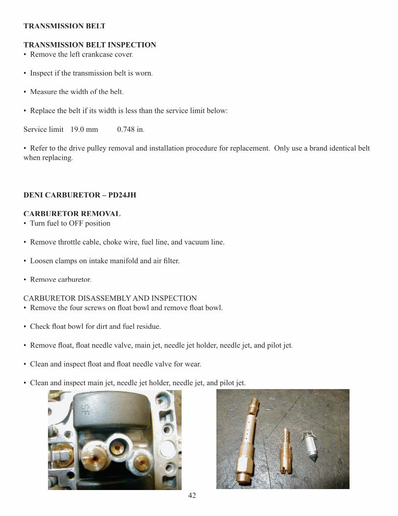
• Remove fl oat, fl oat needle valve, main jet, needle jet holder, needle jet, and pilot jet.
• Clean and inspect fl oat and fl oat needle valve for wear.
• Clean and inspect main jet, needle jet holder, needle jet, and pilot jet.
42
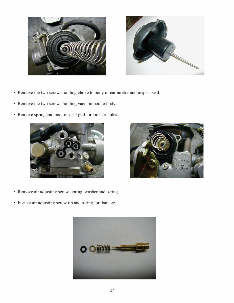
• Remove the two screws holding choke to body of carburetor and inspect seal.
• Remove the two screws holding vacuum pod to body.
• Remove spring and pod; inspect pod for tares or holes.
• Remove air adjusting screw, spring, washer and o-ring.
• Inspect air adjusting screw tip and o-ring for damage.
43
CARBURETOR CLEANINGWARNING Always wear eye protection when working with cleaning agents.
• Clean the carburetor body, jets, and all the air passages in body with carburetor cleaner.
Note: It may be necessary to soak parts in a high caustic carburetor cleaner.Do not soak rubber parts. (O-rings, needle valve, vacuum slide diaphragm etc.) Instead, clean rubber parts with mild detergent and hot water.
• Use carburetor cleaner or contact cleaner to check passages in body making sure that they are not obstructed.
• Use low-pressure air to dry all components.
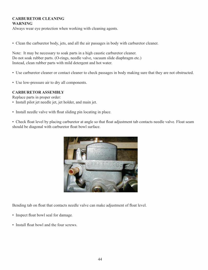
CARBURETOR ASSEMBLY Replace parts in proper order:• Install pilot jet needle jet, jet holder, and main jet.
• Install needle valve with fl oat sliding pin locating in place.
• Check fl oat level by placing carburetor at angle so that fl oat adjustment tab contacts needle valve. Float seam should be diagonal with carburetor fl oat bowl surface.
Bending tab on fl oat that contacts needle valve can make adjustment of fl oat level.
• Inspect fl oat bowl seal for damage.
• Install fl oat bowl and the four screws.
44
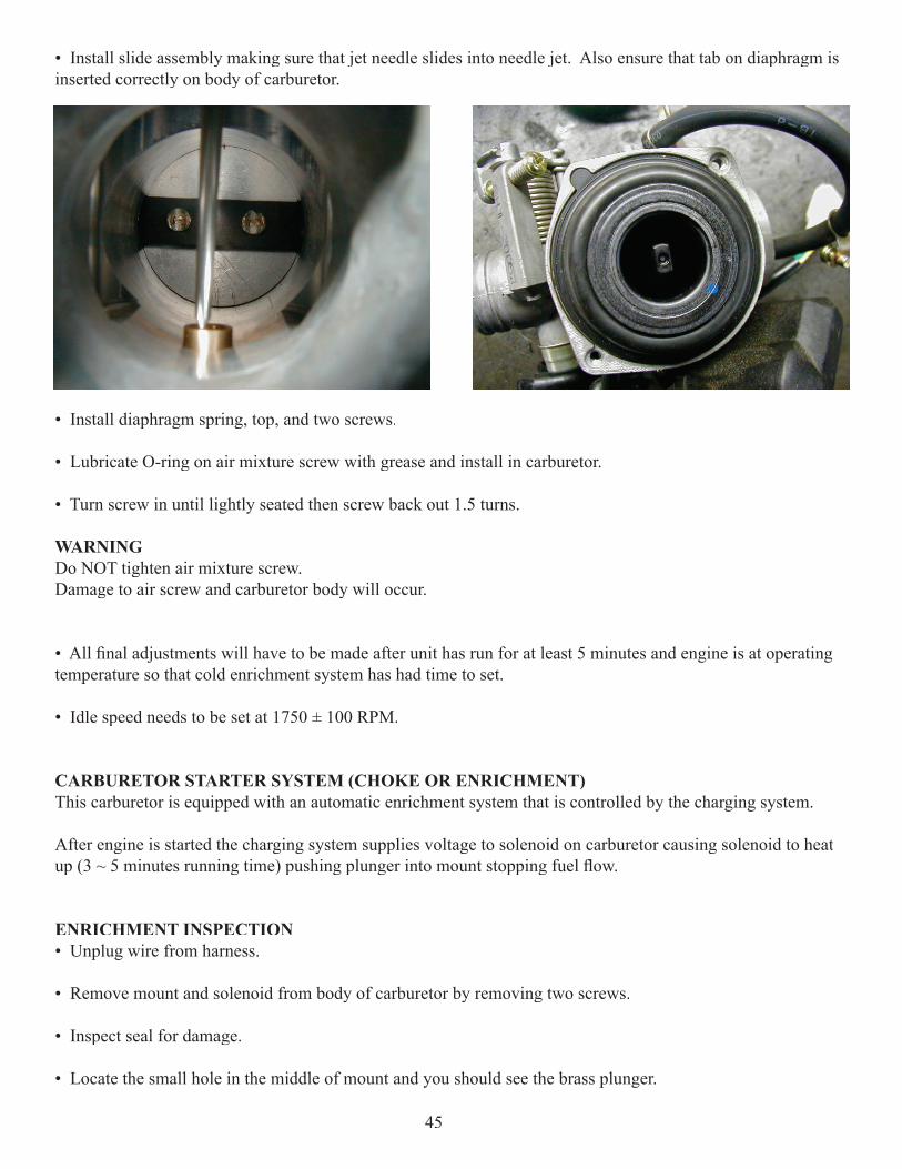
• Install slide assembly making sure that jet needle slides into needle jet. Also ensure that tab on diaphragm is inserted correctly on body of carburetor.
• Install diaphragm spring, top, and two screws.
• Lubricate O-ring on air mixture screw with grease and install in carburetor.
• Turn screw in until lightly seated then screw back out 1.5 turns.
WARNING Do NOT tighten air mixture screw. Damage to air screw and carburetor body will occur.
• All fi nal adjustments will have to be made after unit has run for at least 5 minutes and engine is at operating temperature so that cold enrichment system has had time to set.
• Idle speed needs to be set at 1750 ± 100 RPM.
CARBURETOR STARTER SYSTEM (CHOKE OR ENRICHMENT)This carburetor is equipped with an automatic enrichment system that is controlled by the charging system.
After engine is started the charging system supplies voltage to solenoid on carburetor causing solenoid to heat up (3 ~ 5 minutes running time) pushing plunger into mount stopping fuel fl ow.
ENRICHMENT INSPECTION• Unplug wire from harness.
• Remove mount and solenoid from body of carburetor by removing two screws.
• Inspect seal for damage.
• Locate the small hole in the middle of mount and you should see the brass plunger.
45
• When plunger is covering hole completely the fuel fl ow is shut off.
ENRICHMENT TESTING• Remove the two screws and clamp that secure the solenoid to mount.
• Pull solenoid out of mount.
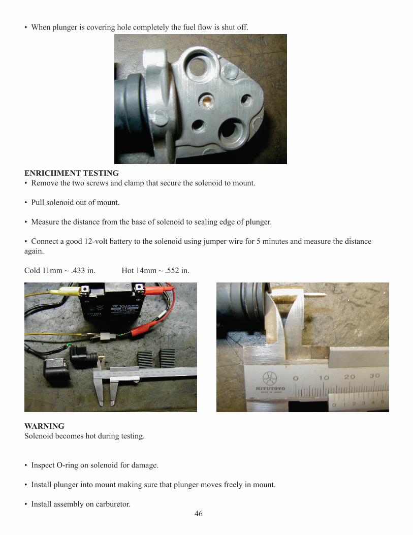
• Measure the distance from the base of solenoid to sealing edge of plunger.
• Connect a good 12-volt battery to the solenoid using jumper wire for 5 minutes and measure the distance again.
Cold 11mm ~ .433 in. Hot 14mm ~ .552 in.
WARNING Solenoid becomes hot during testing.
• Inspect O-ring on solenoid for damage.
• Install plunger into mount making sure that plunger moves freely in mount.
• Install assembly on carburetor. 46
CARBURETOR TROUBLESHOOTING
RICH MIXTURE Symptoms: Fouls spark plug, black exhaust smoke, rough idle, skipping, poor performance, bog, backfi re.
Possible causes:• Air fi lter dirty or plugged• Air intake restricted• Choke plunger stuck• Float level to high• Faulty fl oat needle valve• Loose jets• Worn jet needle or needle jet• Dirt in air passages
LEAN MIXTURESymptoms: Hard starting, popping through intake, low power, runs hot, detonation, surging, idle speed erratic.
Possible causes:• No fuel in tank.• Fuel tank not venting.• Carburetor vent restricted.• Clogged jets or air passage.• Float level to high.• Air fi lter not sealing.• Intake leaking.• Air mixture screw adjustment.
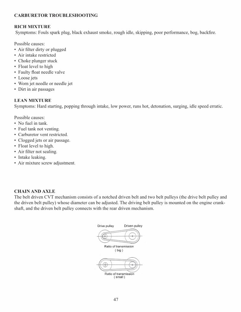
CHAIN AND AXLE The belt driven CVT mechanism consists of a notched driven belt and two belt pulleys (the drive belt pulley and the driven belt pulley) whose diameter can be adjusted. The driving belt pulley is mounted on the engine crank-shaft, and the driven belt pulley connects with the rear driven mechanism.
47
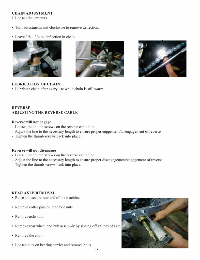
CHAIN ADJUSTMENT• Loosen the jam nuts
• Turn adjustments nut clockwise to remove defl ection.
• Leave 3/8 – 3/4 in. defl ection in chain.
LUBRICATION OF CHAIN• Lubricate chain after every use while chain is still warm
REVERSEADJUSTING THE REVERSE CABLE
Reverse will not engage- Loosen the thumb screws on the reverse cable line. - Adjust the line to the necessary length to ensure proper enggement/disengagement of reverse.- Tighten the thumb screws back into place.
Reverse will not disengage- Loosen the thumb screws on the reverse cable line.- Adjust the line to the necessary length to ensure proper disengagement/engagement of reverse.- Tighten the thumb screws back into place.
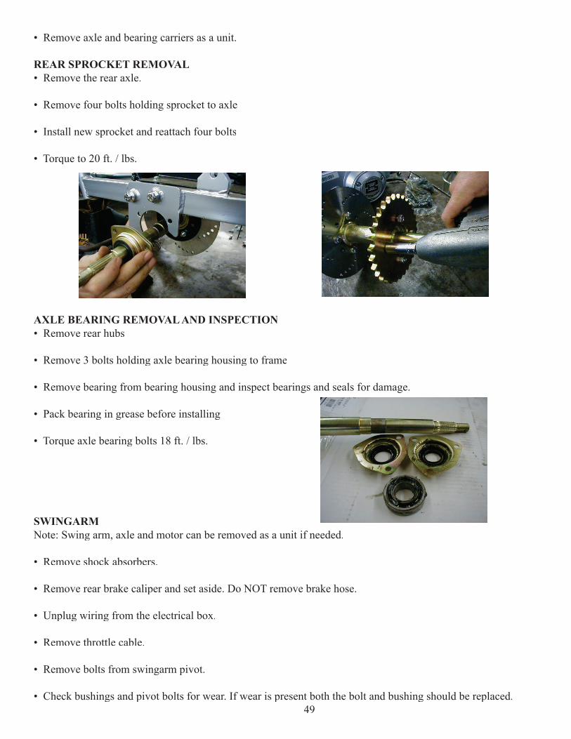
REAR AXLE REMOVAL• Raise and secure rear end of the machine.
• Remove cotter pins on rear axle nuts.
• Remove axle nuts.
• Remove rear wheel and hub assembly by sliding off splines of axle.
• Remove the chain.
• Loosen nuts on bearing carrier and remove bolts. 48
• Remove axle and bearing carriers as a unit.
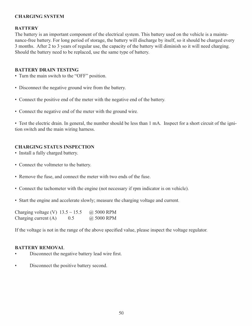
REAR SPROCKET REMOVAL• Remove the rear axle.
• Remove four bolts holding sprocket to axle
• Install new sprocket and reattach four bolts
• Torque to 20 ft. / lbs.
AXLE BEARING REMOVAL AND INSPECTION• Remove rear hubs
• Remove 3 bolts holding axle bearing housing to frame
• Remove bearing from bearing housing and inspect bearings and seals for damage.
• Pack bearing in grease before installing
• Torque axle bearing bolts 18 ft. / lbs.
SWINGARMNote: Swing arm, axle and motor can be removed as a unit if needed.
• Remove shock absorbers.
• Remove rear brake caliper and set aside. Do NOT remove brake hose.
• Unplug wiring from the electrical box.
• Remove throttle cable.
• Remove bolts from swingarm pivot.
• Check bushings and pivot bolts for wear. If wear is present both the bolt and bushing should be replaced.49
CHARGING SYSTEM
BATTERYThe battery is an important component of the electrical system. This battery used on the vehicle is a mainte-nance-free battery. For long period of storage, the battery will discharge by itself, so it should be charged every 3 months. After 2 to 3 years of regular use, the capacity of the battery will diminish so it will need charging. Should the battery need to be replaced, use the same type of battery.
BATTERY DRAIN TESTING• Turn the main switch to the “OFF” position.
• Disconnect the negative ground wire from the battery.
• Connect the positive end of the meter with the negative end of the battery.
• Connect the negative end of the meter with the ground wire.
• Test the electric drain. In general, the number should be less than 1 mA. Inspect for a short circuit of the igni-tion switch and the main wiring harness.
CHARGING STATUS INSPECTION• Install a fully charged battery.
• Connect the voltmeter to the battery.
• Remove the fuse, and connect the meter with two ends of the fuse.
• Connect the tachometer with the engine (not necessary if rpm indicator is on vehicle).
• Start the engine and accelerate slowly; measure the charging voltage and current.
Charging voltage (V) 13.5 ~ 15.5 @ 5000 RPMCharging current (A) 0.5 @ 5000 RPM
If the voltage is not in the range of the above specifi ed value, please inspect the voltage regulator.
BATTERY REMOVAL• Disconnect the negative battery lead wire fi rst.
• Disconnect the positive battery second.
50
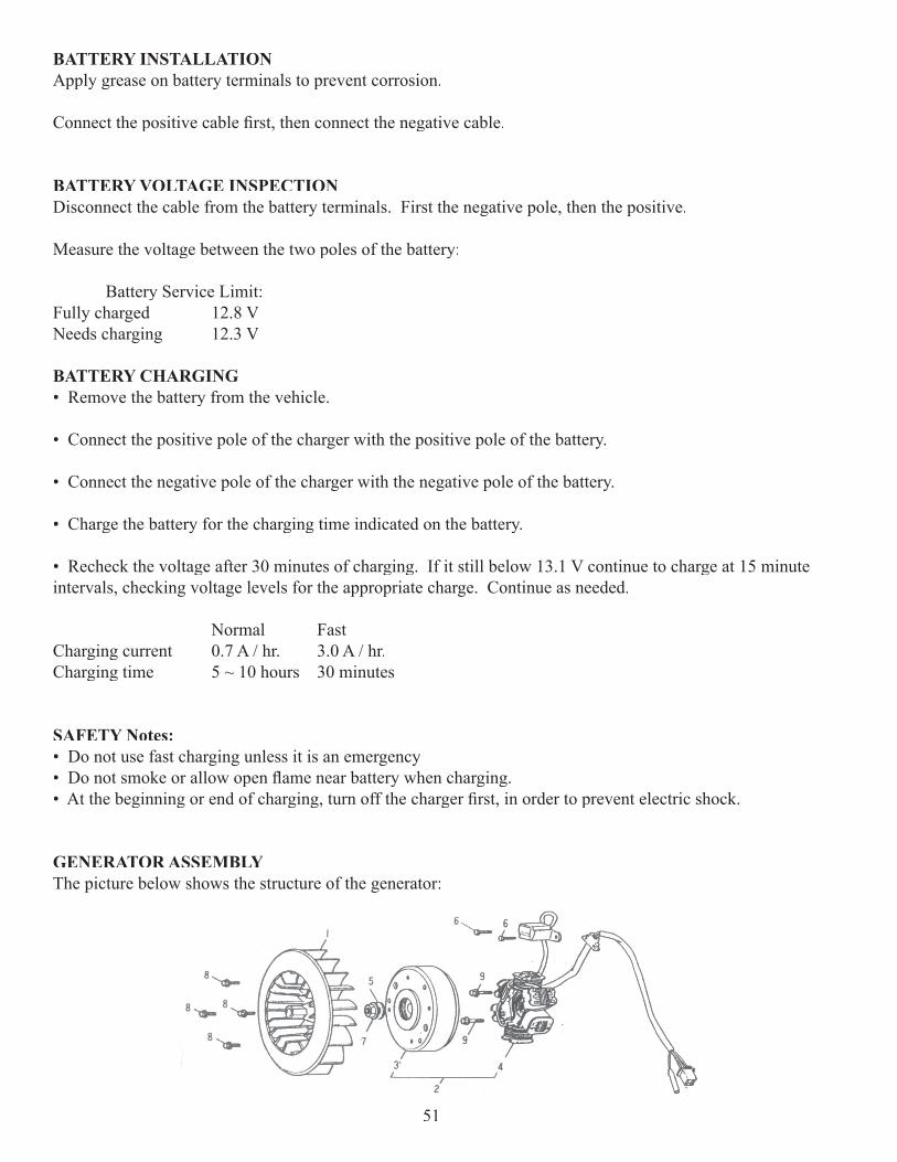
BATTERY INSTALLATIONApply grease on battery terminals to prevent corrosion.
Connect the positive cable fi rst, then connect the negative cable.
BATTERY VOLTAGE INSPECTIONDisconnect the cable from the battery terminals. First the negative pole, then the positive.
Measure the voltage between the two poles of the battery:
Battery Service Limit:Fully charged 12.8 VNeeds charging 12.3 V
BATTERY CHARGING• Remove the battery from the vehicle.
• Connect the positive pole of the charger with the positive pole of the battery.
• Connect the negative pole of the charger with the negative pole of the battery.
• Charge the battery for the charging time indicated on the battery.
• Recheck the voltage after 30 minutes of charging. If it still below 13.1 V continue to charge at 15 minute intervals, checking voltage levels for the appropriate charge. Continue as needed.
Normal FastCharging current 0.7 A / hr. 3.0 A / hr.Charging time 5 ~ 10 hours 30 minutes
SAFETY Notes:• Do not use fast charging unless it is an emergency• Do not smoke or allow open fl ame near battery when charging.• At the beginning or end of charging, turn off the charger fi rst, in order to prevent electric shock.
GENERATOR ASSEMBLYThe picture below shows the structure of the generator:
51
GENERATOR ASSEMBLY COMPONENTS1. Cooling fan2. Generator assembly3. Flywheel comp.4. Stator comp.5. Washer6. Bolt7. Nut8. Bolt9. Bolt
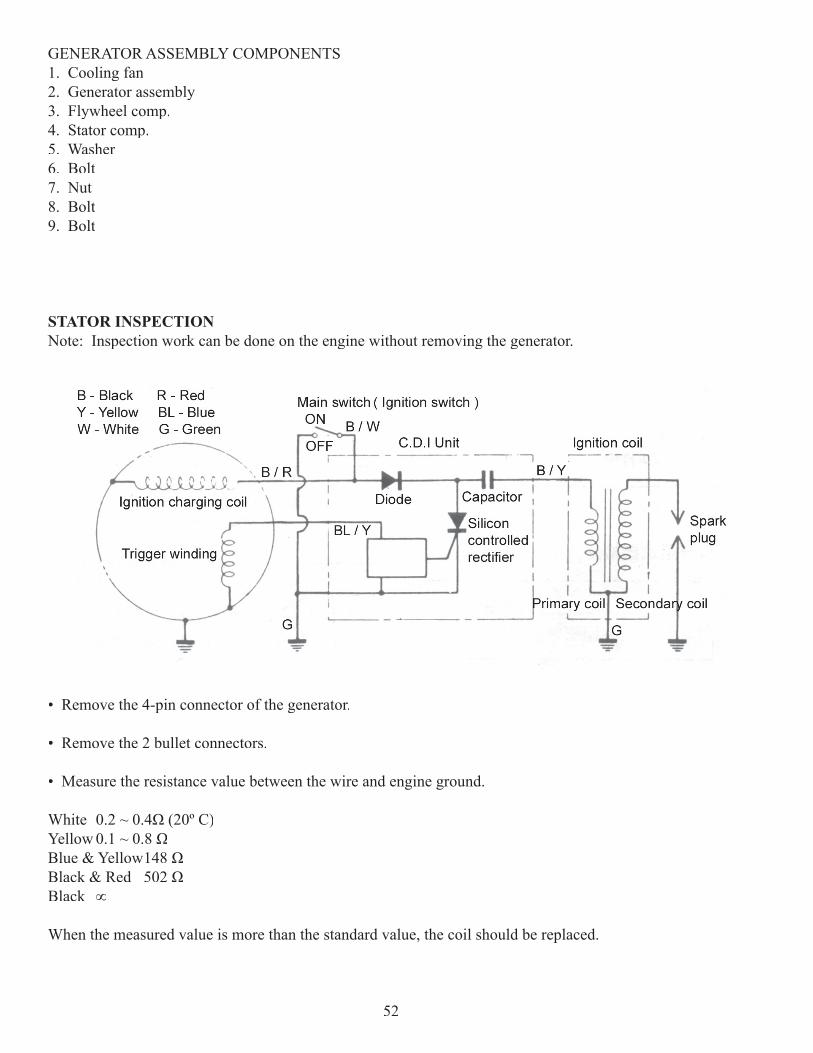
STATOR INSPECTIONNote: Inspection work can be done on the engine without removing the generator.
• Remove the 4-pin connector of the generator.
• Remove the 2 bullet connectors.
• Measure the resistance value between the wire and engine ground.
White 0.2 ~ 0.4Ω (20º C)Yellow 0.1 ~ 0.8 ΩBlue & Yellow 148 ΩBlack & Red 502 ΩBlack ∞
When the measured value is more than the standard value, the coil should be replaced.
52
GENERATOR REMOVAL AND INSPECTION
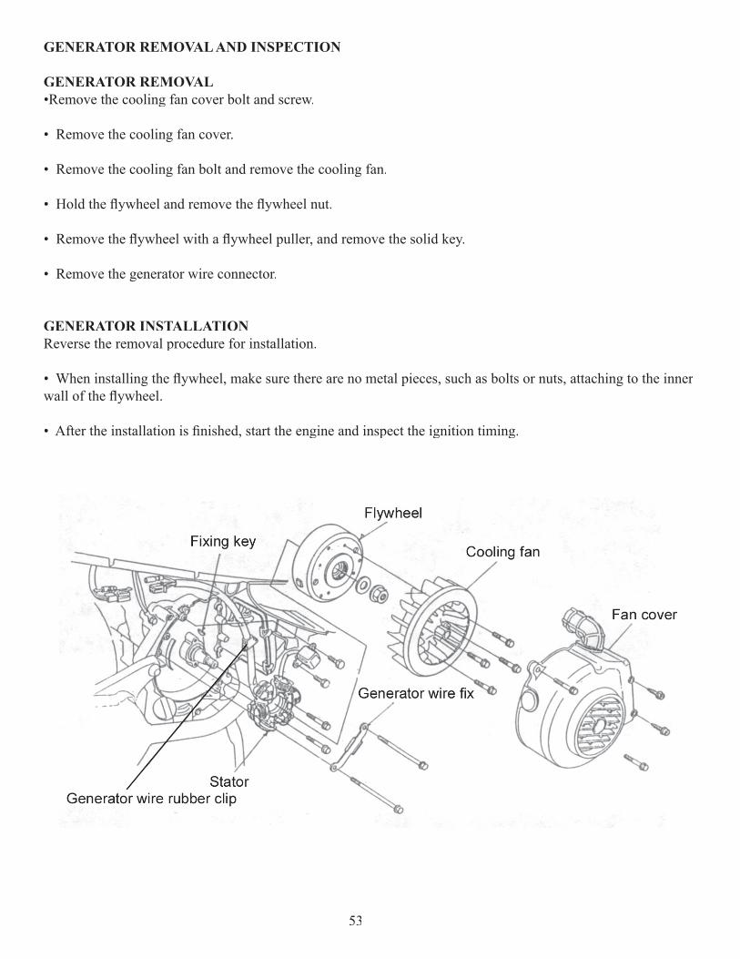
GENERATOR REMOVAL•Remove the cooling fan cover bolt and screw.
• Remove the cooling fan cover.
• Remove the cooling fan bolt and remove the cooling fan.
• Hold the fl ywheel and remove the fl ywheel nut.
• Remove the fl ywheel with a fl ywheel puller, and remove the solid key.
• Remove the generator wire connector.
GENERATOR INSTALLATIONReverse the removal procedure for installation.
• When installing the fl ywheel, make sure there are no metal pieces, such as bolts or nuts, attaching to the inner wall of the fl ywheel.
• After the installation is fi nished, start the engine and inspect the ignition timing.
53
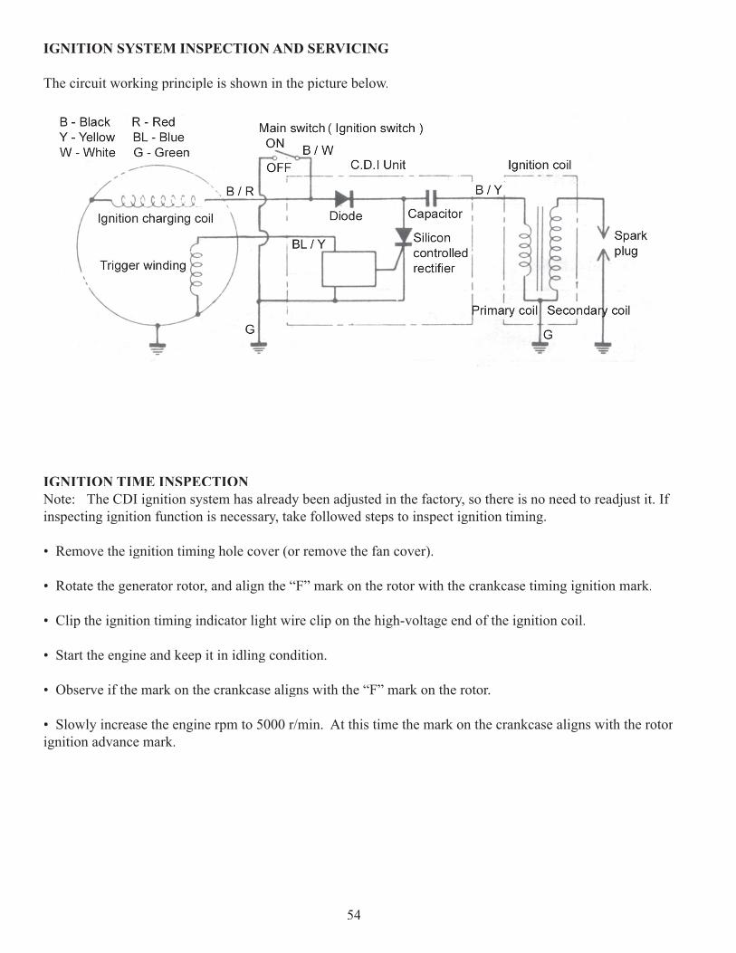
IGNITION SYSTEM INSPECTION AND SERVICING
The circuit working principle is shown in the picture below.
IGNITION TIME INSPECTIONNote: The CDI ignition system has already been adjusted in the factory, so there is no need to readjust it. If inspecting ignition function is necessary, take followed steps to inspect ignition timing.
• Remove the ignition timing hole cover (or remove the fan cover).
• Rotate the generator rotor, and align the “F” mark on the rotor with the crankcase timing ignition mark.
• Clip the ignition timing indicator light wire clip on the high-voltage end of the ignition coil.
• Start the engine and keep it in idling condition.
• Observe if the mark on the crankcase aligns with the “F” mark on the rotor.
• Slowly increase the engine rpm to 5000 r/min. At this time the mark on the crankcase aligns with the rotor ignition advance mark.
54
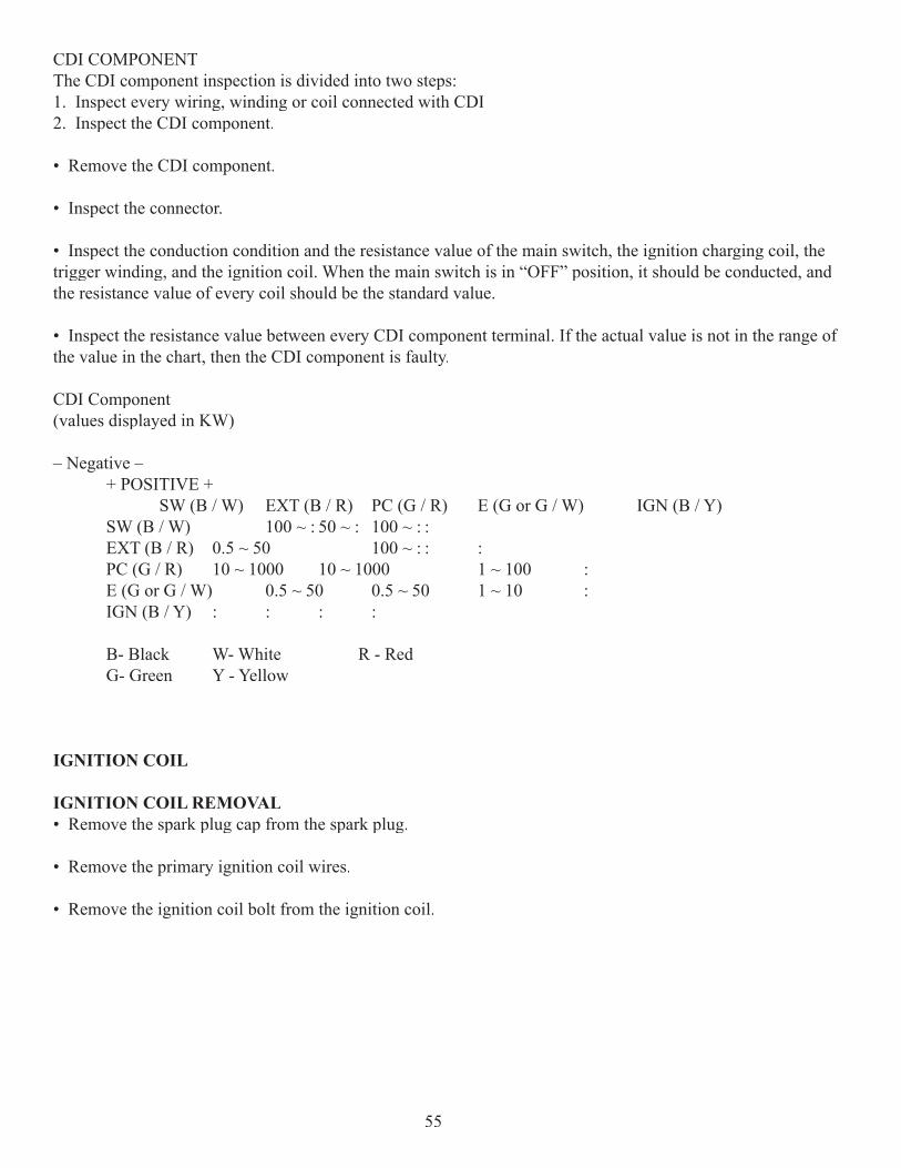
CDI COMPONENTThe CDI component inspection is divided into two steps:1. Inspect every wiring, winding or coil connected with CDI2. Inspect the CDI component.
• Remove the CDI component.
• Inspect the connector.
• Inspect the conduction condition and the resistance value of the main switch, the ignition charging coil, the trigger winding, and the ignition coil. When the main switch is in “OFF” position, it should be conducted, and the resistance value of every coil should be the standard value.
• Inspect the resistance value between every CDI component terminal. If the actual value is not in the range of the value in the chart, then the CDI component is faulty.
CDI Component(values displayed in KW)
– Negative – + POSITIVE + SW (B / W) EXT (B / R) PC (G / R) E (G or G / W) IGN (B / Y) SW (B / W) 100 ~ : 50 ~ : 100 ~ : : EXT (B / R) 0.5 ~ 50 100 ~ : : : PC (G / R) 10 ~ 1000 10 ~ 1000 1 ~ 100 : E (G or G / W) 0.5 ~ 50 0.5 ~ 50 1 ~ 10 : IGN (B / Y) : : : :
B- Black W- White R - Red G- Green Y - Yellow
IGNITION COIL
IGNITION COIL REMOVAL• Remove the spark plug cap from the spark plug.
• Remove the primary ignition coil wires.
• Remove the ignition coil bolt from the ignition coil.
55
IGNITION COIL INSTALLATION•Reverse the removal procedure for installation.
Note: When installing, connect the blue wire from the CDI to the green terminal of the ignition coil, and con-nect the black wire to the second terminal.
PRIMARY IGNITION COIL INSPECTIONStandard Value 0.1 ~ 1.0 Ω (20º C)
If the resistance value is -, it indicates the coil is broken and should be replaced.
SECONDARY IGNITION COIL INSPECTIONInstall the spark plug cap, and measure the resistance value of the secondary ignition coil.Standard Value 7 ~ 9Ω (20º C)
The resistance value is in the standard range indicates it is good; however, - indicates the coil is broken.Remove the spark plug cap, and measure the resistance value of the secondary ignition coil. Standard Value 2 ~ 4Ω (20º C)
SPARK PLUG – NGK C7HSA
• Clean up the carbon around the spark plug to prevent it from dropping into the cylinder when removing the spark plug.
• Remove the spark plug.
Note: When installing, connect the black/yellow wire of the primary ignition coil with the black/yellow connec-tor of CDI, and the green wire with the green connector of CDI.
• Clean up the fi lth and carbon accumulation on the spark plug with a steel brush or a blade.
• Inspect the spark plug gap, in general it should be about:
0.6 ~ 0.7mm 0.024 ~ 0.028 in.
• When the carbon accumulation and wear of the spark plug are too serious, replace the spark plug. Replace with the spark plug of the same specifi cation.
56
REGULATOR RECTIFIER
MAIN WIRING – SUB ELECTRIC CIRCUIT CONDITION INSPECTION• Remove the 4-pin connector of the regulate rectifi er.
• Measure the conducting status between the main wiring terminals according to the previous wiring diagram.
To check the wiring harness:
Positive lead on battery + (red wire) – Negative to ground (black wire) Measures battery voltagePositive lead + (black wire) – Negative to ground Tests Conductivity
Lighting coil + (yellow wire) – Negative to ground• (remove the resistor and the side auto-starter plug) Generally 0.1 ~ 0.8 �
Charging coil + (the white wire) – Negative to ground Generally 0.2 ~ 2.0 �
To check the regulator rectifi er: W(White) Y(Yellow) R(Red) G(Green)W(White) : 3 ~ 100 K� :Y(Yellow) : : 5 ~ 100 K�R(Red) : : :G(Green) : 5 ~ 100 K� :
REGULATOR RECTIFIER INSPECTION• Inspect the regulator rectifi er connection.
• Measure the resistance value between every regulator rectifi er terminal.
If the resistance value between the terminals does not match the value in the table above, replace the regulator rectifi er.
RESISTOR
RESISTOR RESISTANCE VALUE MEASUREMENTMeasure the resistance value between the resistor wire and the vehicle body. It is normal when the actual value is in the range of �1� value marked on the resistor. If the resistance value is out of the �1�range then it needs to be replaced
57
ELECTRICAL STARTING MECHANISM
CONTROLLING MECHANISMSTARTER RELAY INSPECTION
Turn the main switch to the “ON” position, and press the starting motor button, and listen for a “click” sound. If there is, it is normal; if there isn’t, follow the procedures below:
Inspect if the brake switch is conductive. Turn the main switch on and hold the brake lever.
Measure the voltage between the inlet line (the green/yellow line) starting relay and the ground wire of the body.
The voltmeter reading should be close to the battery voltage. If not, then the brake switch is bad.
Inspect if the start button is conductive. At this time, remove the starting relay inlet line (the green/yellow line).
Connect the yellow/red line with the ground wire, and press the start button. It should be conductive between the yellow/red line and the ground wire, or the start button, is bad.
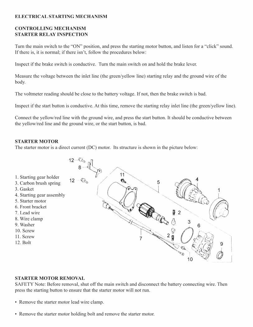
STARTER MOTORThe starter motor is a direct current (DC) motor. Its structure is shown in the picture below:
1. Starting gear holder3. Carbon brush spring3. Gasket4. Starting gear assembly5. Starter motor6. Front bracket7. Lead wire8. Wire clamp9. Washer10. Screw11. Screw12. Bolt
STARTER MOTOR REMOVALSAFETY Note: Before removal, shut off the main switch and disconnect the battery connecting wire. Then press the starting button to ensure that the starter motor will not run.
• Remove the starter motor lead wire clamp.
• Remove the starter motor holding bolt and remove the starter motor.
• Roll up the rubber, water-resistant, cover and remove the starter motor joint.
• Remove the motor case bolt, the carbon brush seat, and the motor case.
ARMATURE INSPECTIONInspect the armature surface for uneven wear, damage, or a change in color caused by high temperatures.
Note: Do not use sandpaper to grind. Do not wash with any solvent which can damage insulation.
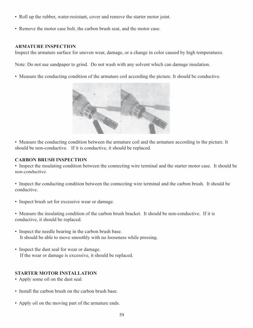
• Measure the conducting condition of the armature coil according the picture. It should be conductive.
• Measure the conducting condition between the armature coil and the armature according to the picture. It should be non-conductive. If it is conductive, it should be replaced.
CARBON BRUSH INSPECTION• Inspect the insulating condition between the connecting wire terminal and the starter motor case. It should be non-conductive.
• Inspect the conducting condition between the connecting wire terminal and the carbon brush. It should be conductive.
• Inspect brush set for excessive wear or damage.
• Measure the insulating condition of the carbon brush bracket. It should be non-conductive. If it is conductive, it should be replaced.
• Inspect the needle bearing in the carbon brush base. It should be able to move smoothly with no looseness while pressing.
• Inspect the dust seal for wear or damage. If the wear or damage is excessive, it should be replaced.
STARTER MOTOR INSTALLATION• Apply some oil on the dust seal.
• Install the carbon brush on the carbon brush base.
• Apply oil on the moving part of the armature ends.
59
• Put the carbon brush into the bracket, and then install the carbon brush base.
Note: Do not damage the contact area of the carbon brush and the armature. While installing, do not damage the lip of the dust seal.
• Mount the new O-ring on the carbon brush base.
• Install armature into starter motor case, making sure not to disturb the carbon brushes.
• Tighten motor case bolts.
Note: Because motor case is magnetic, make sure the starter motor case is free of metal particles.Before install the starter motor on the vehicle after assemble it, fi rst connect the lead wires and inspect if the motor can run normally.
• Apply oil on the O-ring, and install the starter motor.
• Tighten holding bolts.
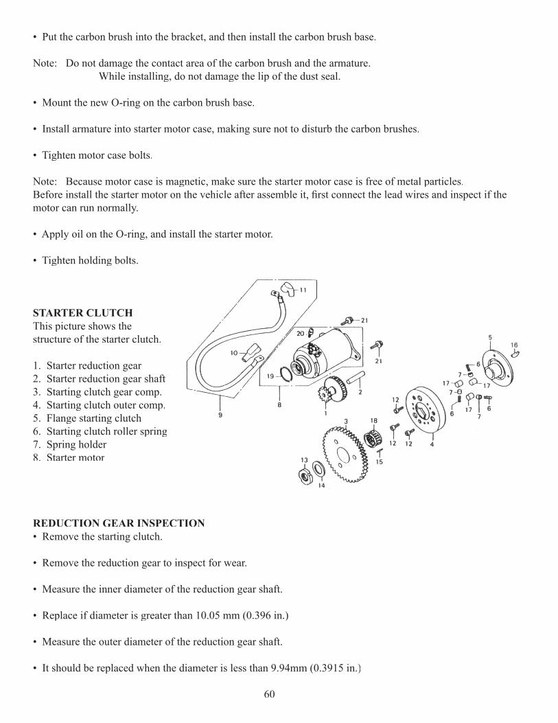
STARTER CLUTCHThis picture shows the structure of the starter clutch.
1. Starter reduction gear2. Starter reduction gear shaft3. Starting clutch gear comp.4. Starting clutch outer comp.5. Flange starting clutch6. Starting clutch roller spring7. Spring holder8. Starter motor
REDUCTION GEAR INSPECTION• Remove the starting clutch.
• Remove the reduction gear to inspect for wear.
• Measure the inner diameter of the reduction gear shaft.
• Replace if diameter is greater than 10.05 mm (0.396 in.)
• Measure the outer diameter of the reduction gear shaft.
• It should be replaced when the diameter is less than 9.94mm (0.3915 in.)
60
ENGAGING MECHANISM
STARTING CLUTCH REMOVAL• Remove fan.
• Remove fl ywheel.
• Remove stator plate assembly.
• Remove the right crankcase cover.
• Remove the left crankcase cover.
• Remove the starting clutch nut.
Note: The nut is a left-handed thread.
• Remove the starting clutch set.
STARTING CLUTCH INSPECTION• Inspect if the movement between the clutch and the driving gear is normal.- When turning clockwise, the driving gear should turn smoothly. - The driving gear should lock when turned counterclockwise.
• Inspect if there is any abrasion or damage on the surface between the driving gear and the needle bearing. It should be replaced when the surface is unusual.
• Measure the inner diameter of the driving gear. It should be replaced when the diameter is more than the ser-vice limit.
Service limit 32.06 mm 1.2625 in.
• Inspect the condition of the needle bearing. If damage is extensive it should be replaced.
• Inspect if there is any damage to the surface between the outer clutch component and the roller.
• Inspect for damage to the roller.
• Inspect for damage to the spring.
61
• Measure the inner diameter of the fl ange clutch. It should be replaced when the diameter is more than the service limit.
Service limit 27.94mm 1.100 in.
STARTING CLUTCH INSTALLATION• Install the spring, the roller, and the top pin on the body of the clutch.
• Align the dowel pin on the fl ange clutch with the hole on the clutch body, then install.
• Apply Loctite 242 on the outer clutch component bolt and fasten.
• Apply some oil on the needle bearing and the driving gear and put the outer clutch component on.
• Align the groove of the woodruff key on the crank and install the starting clutch.
• Apply some oil on the reduction gear and the reduction gear shaft, then install.
• Hold the drive while simultaneously fastening the clutch nut.
• Install the right crankcase cover.
• Install the left crankcase cover.
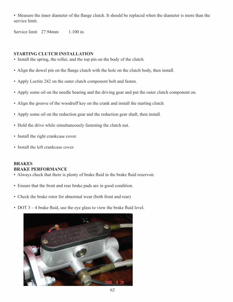
BRAKESBRAKE PERFORMANCE• Always check that there is plenty of brake fl uid in the brake fl uid reservoir.
• Ensure that the front and rear brake pads are in good condition.
• Check the brake rotor for abnormal wear (both front and rear).
• DOT 3 – 4 brake fl uid, use the eye glass to view the brake fl uid level.
62
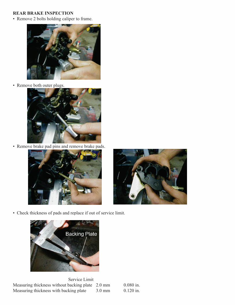
REAR BRAKE INSPECTION• Remove 2 bolts holding caliper to frame.
• Remove both outer plugs.
• Remove brake pad pins and remove brake pads.
• Check thickness of pads and replace if out of service limit.
Service LimitMeasuring thickness without backing plate 2.0 mm 0.080 in.Measuring thickness with backing plate 3.0 mm 0.120 in.
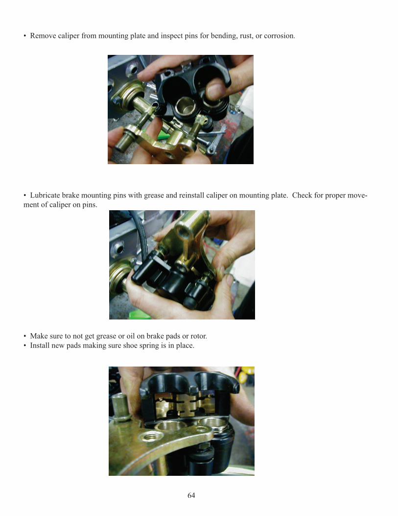
• Remove caliper from mounting plate and inspect pins for bending, rust, or corrosion.
• Lubricate brake mounting pins with grease and reinstall caliper on mounting plate. Check for proper move-ment of caliper on pins.
• Make sure to not get grease or oil on brake pads or rotor.• Install new pads making sure shoe spring is in place.
64
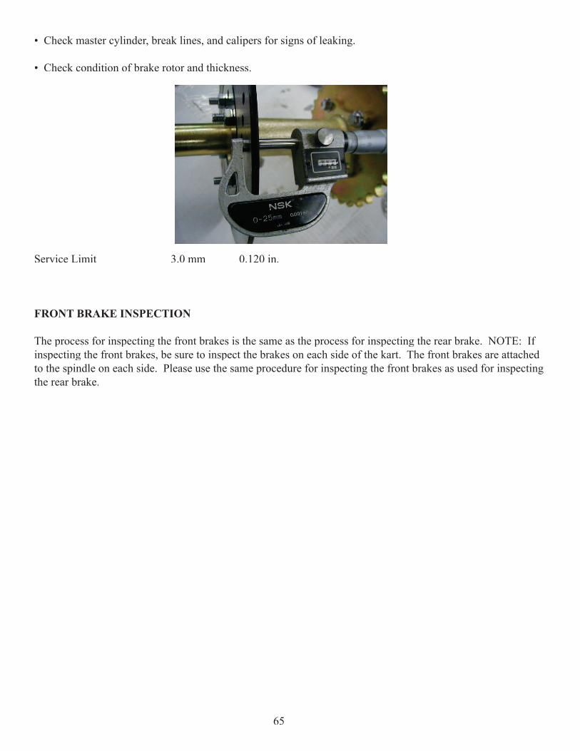
• Check master cylinder, break lines, and calipers for signs of leaking.
• Check condition of brake rotor and thickness.
Service Limit 3.0 mm 0.120 in.
FRONT BRAKE INSPECTION
The process for inspecting the front brakes is the same as the process for inspecting the rear brake. NOTE: If inspecting the front brakes, be sure to inspect the brakes on each side of the kart. The front brakes are attached to the spindle on each side. Please use the same procedure for inspecting the front brakes as used for inspecting the rear brake.
65
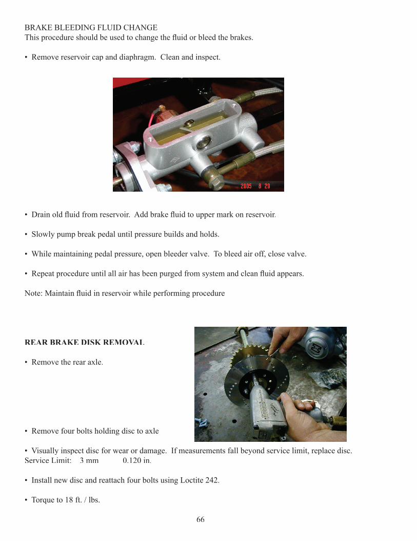
BRAKE BLEEDING FLUID CHANGEThis procedure should be used to change the fl uid or bleed the brakes.
• Remove reservoir cap and diaphragm. Clean and inspect.
• Drain old fl uid from reservoir. Add brake fl uid to upper mark on reservoir.
• Slowly pump break pedal until pressure builds and holds.
• While maintaining pedal pressure, open bleeder valve. To bleed air off, close valve.
• Repeat procedure until all air has been purged from system and clean fl uid appears.
Note: Maintain fl uid in reservoir while performing procedure
REAR BRAKE DISK REMOVAL
• Remove the rear axle.
• Remove four bolts holding disc to axle
• Visually inspect disc for wear or damage. If measurements fall beyond service limit, replace disc. Service Limit: 3 mm 0.120 in.
• Install new disc and reattach four bolts using Loctite 242.
• Torque to 18 ft. / lbs.
66
FRONT END ADJUSTMENTS
CASTER (1 Degree Negative)
CAMBER (1 Degree Negative)
TOW- The cart should have (1 Inch) of toe in after the front tires have been centered.
To ensure that the tires have been centered, turn the steering wheel all the way to the right. Measure the distance from the edge of the tire to the top A-Arm. After obtaining this measurement, turn the wheel all the way to the left and take the same measurement. The two measurements should be the same.
67
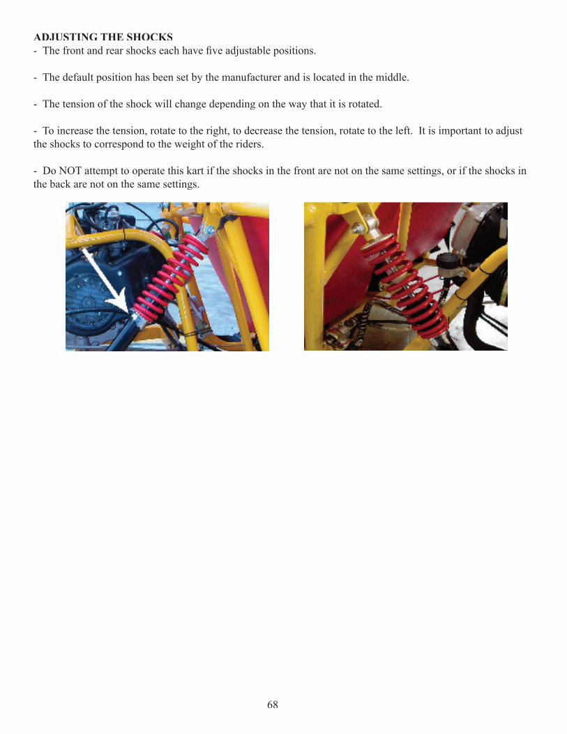
ADJUSTING THE SHOCKS- The front and rear shocks each have fi ve adjustable positions.
- The default position has been set by the manufacturer and is located in the middle.
- The tension of the shock will change depending on the way that it is rotated.
- To increase the tension, rotate to the right, to decrease the tension, rotate to the left. It is important to adjust the shocks to correspond to the weight of the riders.
- Do NOT attempt to operate this kart if the shocks in the front are not on the same settings, or if the shocks in the back are not on the same settings.
68
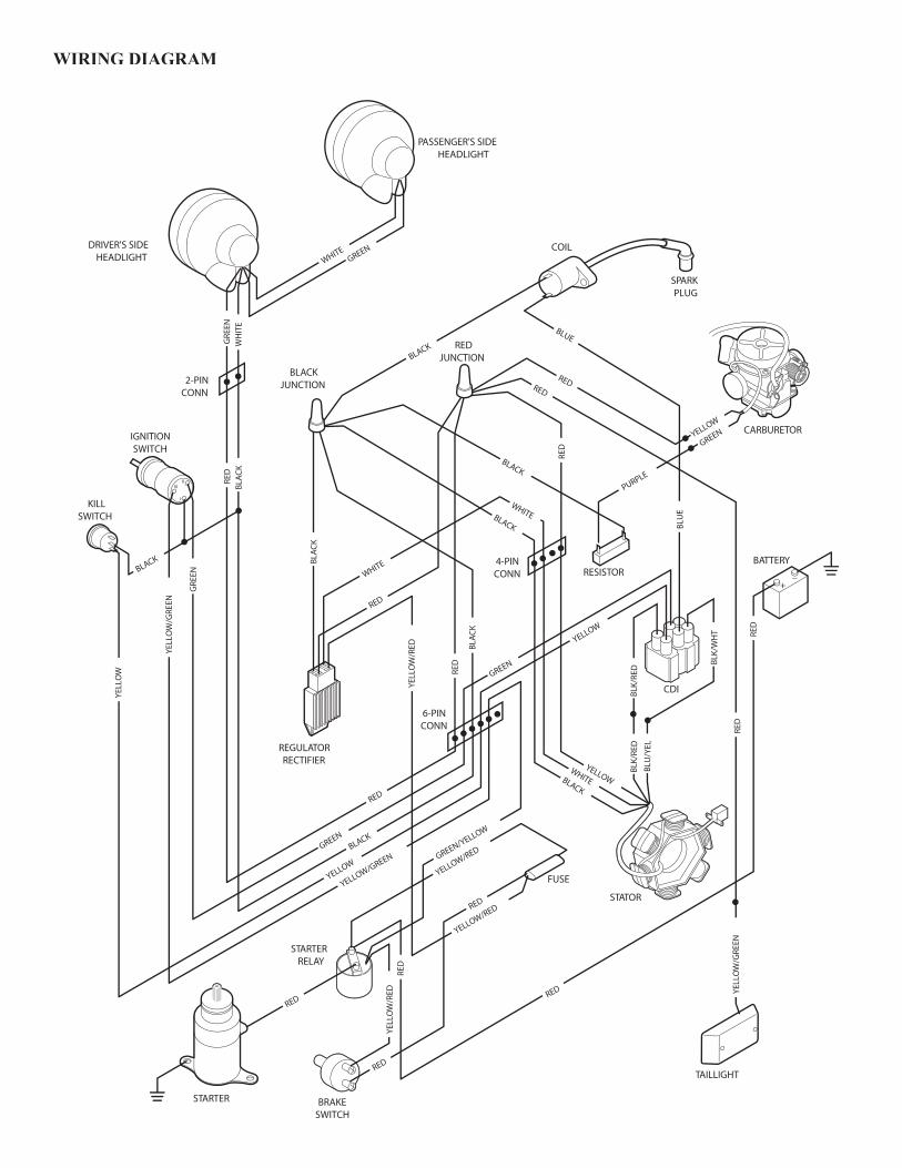
����������������������
�������������������������
�������������
�����������
��������������
�����������
������
����������
������������
�������
������������������
����������
���������
���������
���������
���������
����
���
�������
����
���������
�
�����
����������
���
���
���
���
����
��
���
���
����
����������
����������
���
���
����
������������
���
���
����
��
������������
������
������
������
������
���
���
���
���
���
���
���
���
���
���
���
������
���
���
�
������
�����
�����
�����
���
��
�����
���
����
���
���
�
���
����
���
����
�����
�����
����
�����
�����
�����
�����
������
���
��
����
���
��
���
��
���
��
�����
�����
�����
WIRING DIAGRAM

Notes
70

Notes

Tomberlin Outdoor3123 Washington Road
Augusta, GA 30907