Embed Size (px)
Citation preview
0r A142 042 PURDUE PLANE STRUCTURES ANALYZER 11A COMPUTERIZED WOOD 1/ENGINEERING SYSTEM 1983 VERSIONU) FOREST PRODUCTS LAB
UNLSIIDMADISONWI SIK<SUDDARHET AL MAY 84FSGTR-FPL40
NJ D
a" l~?ingj ,
MICROCOPY RESOLUTION TEST CHARTNATIONAL BUREAU OF SIANDARDS, 1963 A
N'~jm
0Nq~aYintm
~ I0
.4,
I
p.
............
Preface Table of Contents
This manuscript was written as a guide to the use of Pagethe updated version of the Purdue Plane Structures Introduction ................................. 1Analyzer (PPSA II) computer program. For convenience, Program Objectives .......................... 1it has been divided into five sections. The first section, Input Requirements .......................... 2for those unfamiliar with PPSA, is a basic introduction Structural Analog .......................... 2to its background, use, and versatility. The second sec- Loads .................................... 4tion provides instruction for the preparation of required Program Operation .......................... 4data input. The third section presents a sample output Preparation of Program Input ................... 5and the fourth discusses the significance of the in- Identification ............................... 5teraction analysis. The final section, entitled Special Problem Size ............................... 6Topics, provides guidelines for modeling more complex Member Properties .......................... 6structural systems. Stress Adjustment Factor .................... 7
Point Coordinates ........................... 7For those interested in copying, updating, or modifying Structural Assembly ......................... 8the program, Appendices A and B provide information Reactions .................................. 9regarding array dimensions and input format. Load Information and Interaction Interpretation.. 10
Concentrated Loads ... ...................... 10Arr g ents c mad onbtain c y of PPA I Uniform Loads .......................... 11b on cting Nodal Loads ................................ 11
Example of Program Output 12U. D.A. re Se ce Analog Summary ............................ 12S te an ate res Analysis Summary .......................... 16c Fore oduc La orato Significance of Output in Table IX ............... 21
Bo 5 Interaction Analysis ......................... 21is s.5 05 Effective Column Length ..................... 22
)2 57 Lateral Support of a Member .................. 22Interaction Indices .......................... 23
Special Topics ............................... 24FIRL Reaction .............................. 24Further Application Flexibility ................. 25
Acknowledgments ........................... 27Literature Cited .............................. 27Appendix A .................. ............... 28Appendix B .................................. 36
DTICELECTE..
JUN 1 4 1984
Accessicn For ~L C ENTTS GF BDTI7 TUB H /Jus 1 f C;X.t~ - -."
By- Purdue Plane Structures Analyzer 11Di.t r i hut I on/ 1983 Version
Availabllit7 Codes This program is intended to facilitate the analysis ofAv ,il a:nd/or wood structures. It gives an accurate report of struc-
Dist Special tural response of the input analog. Accuracy of theanalog and Interpretation cf structural adequacy arethe responsibility of the user.
r P~WON STATEMENTA! Apvw,,d 1=Vubieeial
.......... .................. .. ...".............. .dli =
Purdue PlaneStructuresAnalyzer I1:A Computerized WoodEngineering System'Stanley K. Suddarth, Professor of Wood Engineering,School of Forestry, Purdue UniversityandRonald W. Wolfe, Research EngineerForest Products Laboratory
Introduction
The Purdue Plane Structures Analyzer (PPSA) is a The question of memory storage requirementscomputer program for the analysis of wood structures, frequently governs the usefulness of a computerIt is a tool for accurate prediction of the behavior of any program. PPSA II allows for changes to be made tostable wood truss or frame that can be represented by a accommodate computer memory or problem sizetwo-dimensional analog. Introduced by Suddarth in limitations. As the program is presently set up, it and1972, it has found repeated application in areas of data storage require 27 K words of memory on adesign and research. Its most frequest use has been UNIVAC 1110 computer.the analysis of wood trusses.
Over the 10 years from 1972 to 1982, a number of Program Objectivesdesign changes have been Implemented in the National The PPSA II program performs an analysis of an analogDesign Specification (NDS) for Wood Construction of a real structure. It must be recognized that(NFPA 1982). Design changes for member stability, computers do not substitute for engineers; computerscombined compression-bending loads, and buckling are only a tool. It is the engineer's responsibility tostiffness of sheathed compression members recognize the limitations of the output to meet all thenecessitated modification of PPSA, giving rise to the needs of a total design and to judge the adequacy ofdevelopment of PPSA II. This program incorporates the analog in modeling real performance.these NDS changes as well as providing addedversatility for more effective analog modeling. Structural design requires awareness of various analog
assumptions. These assumptions include both detailsInput and output formats for PPSA II are basically the of the analog configuration and the loadingsame as those used in the original version (Suddarth arrangement. Analog configuration assumptions that1972). They have undergone minor changes to provide may affect structural response include reactions andadded versatility in modeling actual structures. end fixity as well as elastic properties of individual
members. Load assumptions include magnitude,The program has been set up to use a single unit of location, and direction of applied loads. To vary theforce--the pound--and a single unit of length-the inch. analog configuration, the entire set of input data mustAny other units may be used if the same basic rule is be reread. Load variations, however, require only thatfollowed in the input data. The heading labels in the the new loads, along with indices that control theprinted output indicate pounds and inches, however, stress adjustment factor and interaction analysisand must be changed to reflect any change In unit. option, be Included as additional cases.
'Prepared In coopeation with Purdue University; the paper Is JournalPo 9532 of the Purdue Agricultural Experiment Station.
(
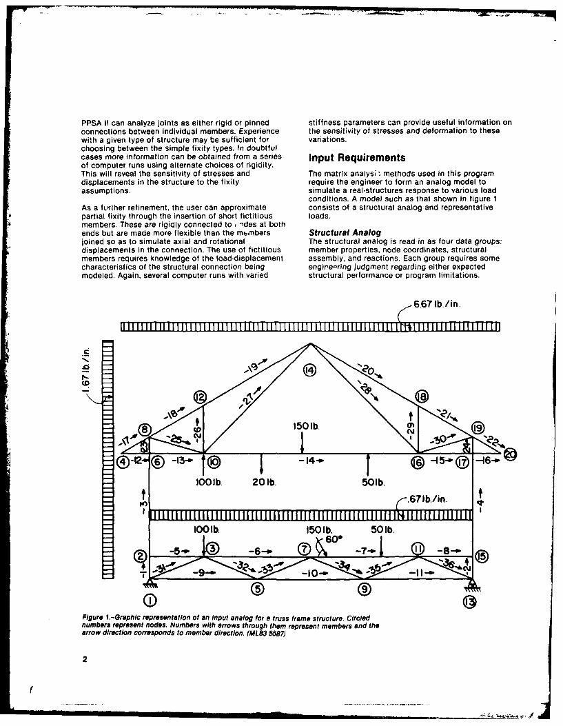
PPSA II can analyze joints as either rigid or pinned stiffness parameters can provide useful information onconnections between individual members. Experience the sensitivity of stresses and deformation to thesewith a given type of structure may be sufficient for variations.choosing between the simple fixity types. In doubtfulcases more information can be obtained from a series Input Requirementsof computer runs using alternate choices of rigidity.This will reveal the sensitivity of stresses and The matrix analys; - methods used in this programdisplacements in the structure to the fixity require the engineer to form an analog model toassumptions, simulate a real-structures response to various load
conditions. A model such as that shown in figure 1As a further refinement, the user can approximate consists of a structural analog and representativepartial fixity through the insertion of short fictitious loads.members. These are rigidly connected to, )des at bothends but are made more flexible than the mt,'nbers Structural Analogjoined so as to simulate axial and rotational The structural analog is read in as four data groups:displacements in the connection. The use of fictitious member properties, node coordinates, structuralmembers requires knowledge of the load-displacement assembly, and reactions. Each group requires somecharacteristics of the structural connection being engire,-ring judgment regarding either expectedmodeled. Again, several computer runs with varied structural performance or program limitations.
6.67 lb./in.
I-.
1501b.
IO01b. 20 lb. 501b.
-.671b/in.
1OO lb. 150 1b. 50 1b.600--.o 3 -6- 7.© --
0 9Figure 1.-Graphic representation of an input analog for a truss frame structure. Circlednumbers represent nodes. Numbers with arrows through them represent members and thearrow direction corresponds to member direction. (ML83 5587)
2
(
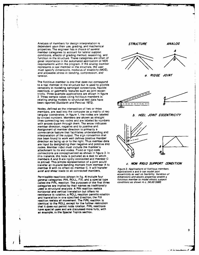
Analysis of members for design interpretation is STRUCTURE ANALOGdependent upon their use, grading, and mechanicalproperties. The engineer has a choice of severalAmember categories to account for lateral supportAconditions, effects of grading method, seasoning, andfunction in the structure. These categories are often ofBgreat importance in the automated application of NDSrequirements within the program. If the analog memberrepresents a real member in the structure, the usermust specify dimensions, modulus of elasticity (MOE),and allowable stress in bending, compression, andtension,.a RID GE JOINT
The fictitious member is one that does not correspondto a real member in the structure but is used to provideversatility in modeling semirigid connections, flexiblereactions, or geometric features such as joint eccen--tricity. Three example applications are shown in figure2. Three sample cases using fictitious members inArelating analog models to structural test data haveB
Nodes, defined as the intersection of two or moremembers, are read into the computer as a matrix of rec-tangular coordinates. In figure 1, the nodes are labeled b. HEEL JOINT ExENTRICI7Yby circled numbers. Members are shown as straightlines connecting two nodes and are labeled by numberswith arrows drawn through them. The arrow indicatesmember direction, negative end to positive end.Assignment of member direction is primarily a/convenience feature that facilitates understanding andinterpretation of the output. The sign convention thatI -has been found to work well defines positive memberI -
* direction as being up or to the right. Thus member dataare input by designating their negative and positive endnodes. Member input must include the member's Aattachment to its end nodes. Fixed or rigid nodeconnections are conceptualized as shown in figure 3. InBthis instance, the node is pictured as a disk to whichmembers A and B are rigidly connected and member Cis pinned. This simple representation of a joint wouldtransfer an in-plane bending moment from member A to c. AVW R#I/D SUPPrT C~ODIOWmember B with no effect on member C. It will transfer Figure 2.--Applications of fictitious members.axial and shear loads to all connected members. Applications a and b can model joint
eccentricity as well as flexibility. Variation ofPermissible reactions (shown in fig. 4) include four dimensions and elastic properties enable ageneral categories: PIN, ROLL, FIX, and a special type fictitious member to model elastic supportcalled the FIRL reaction. The purposes of the first three conditions as shown in c. (A1L83 5588)categories are implied by their names as traditionallyused In structural analysis: A PIN reaction resistshorizontal and vertical translation but offers noresistance to rotation; a ROLL reaction permits rotationand translation in one specified direction; the FIXreaction resists all movement. The FIRL reaction IsIdentical to the ROLL except for the further restrictionthat It does not permit node rotation. FIRL reactionshave special uses and are discussed more fully, withan example, In the Special Topics section.
3
'I~~ ~~~ __ _ __ _ _ __ _ _
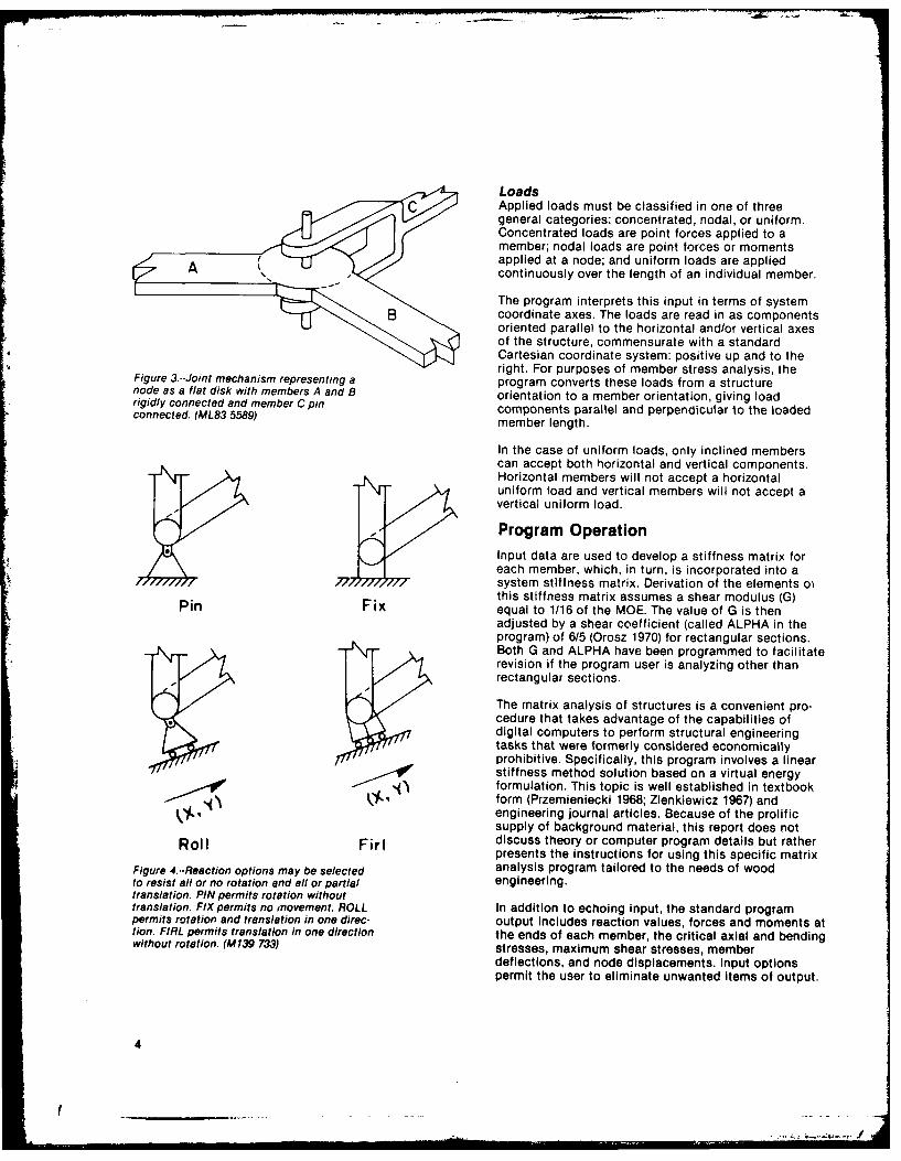
LoadsApplied loads must be classified in one of threegeneral categories: concentrated, nodal, or uniform.Concentrated loads are point forces applied to amember; nodal loads are point forces or momentsapplied at a node; and uniform loads are applied
A continuously over the length of an individual member.
The program interprets this input in terms of systemB coordinate axes. The loads are read in as components
oriented parallel to the horizontal and/or vertical axesof the structure, commensurate with a standardCartesian coordinate system: positive up and to theright. For purposes of member stress analysis, theFigure 3--Joint mechanism representing a program converts these loads from a structure
node as a flat disk with members A and B orientation to a member orientation, giving loadrigidly connected and member C pin components parallel and perpendicular to the loadedconnected. (ML83 559) member length.
In the case of uniform loads, only inclined memberscan accept both horizontal and vertical components.Horizontal members will not accept a horizontaluniform load and vertical members will not accept avertical uniform load.
Program OperationInput data are used to develop a stiffness matrix foreach member, which, in turn, is incorporated into asystem stiffness matrix. Derivation of the elements oithis stiffness matrix assumes a shear modulus (G)Pin Fix equal to 1/16 of the MOE. The value of G is thenadjusted by a shear coefficient (called ALPHA in theprogram) of 6/5 (Orosz 1970) for rectangular sections.Both G and ALPHA have been programmed to facilitaterevision if the program user is analyzing other thanrectangular sections.
The matrix analysis of structures is a convenient pro-cedure that takes advantage of the capabilities ofdigital computers to perform structural engineeringtasks that were formerly considered economicallyprohibitive. Specifically, this program involves a linearstiffness method solution based on a virtual energyformulation. This topic is well established in textbookform (Przemieniecki 1968; Zienkiewicz 1967) andengineering journal articles. Because of the prolificsupply of background material, this report does not
Roll Firl discuss theory or computer program details but ratherpresents the instructions for using this specific matrix
Figure 4--Reaction options may be selected analysis program tailored to the needs of woodto resist all or no rotation and all or partial engineering.translation. PIN permits rotation withouttranslation. FIX permits no movement. ROLL In addition to echoing input, the standard programpermits rotation and translation in one direc- output Includes reaction values, forces and moments attion. FIRL permits translation in one direction the ends of each member, the critical axial and bendingwithout rotation. (M139 733) stresses, maximum shear stresses, member
deflections, and node displacements. Input optionspermit the user to eliminate unwanted items of output.
4
Preparation of Program Input
User-computer communications may make use of either 5.0 Ib/ina keyboard computer terminal or cards for entering the Ibanalog data. In the following discussions, the term II I I II l m i m lI IIinput line or line refers to the data recorded on onecard or one line of type. The PPSA II program isformatted to read input data one line at a time and toidentify individual values by line sequence and locationin the input line. Appendix A shows input data coding 128.8 lb.forms that may be used to facilitate the input process.
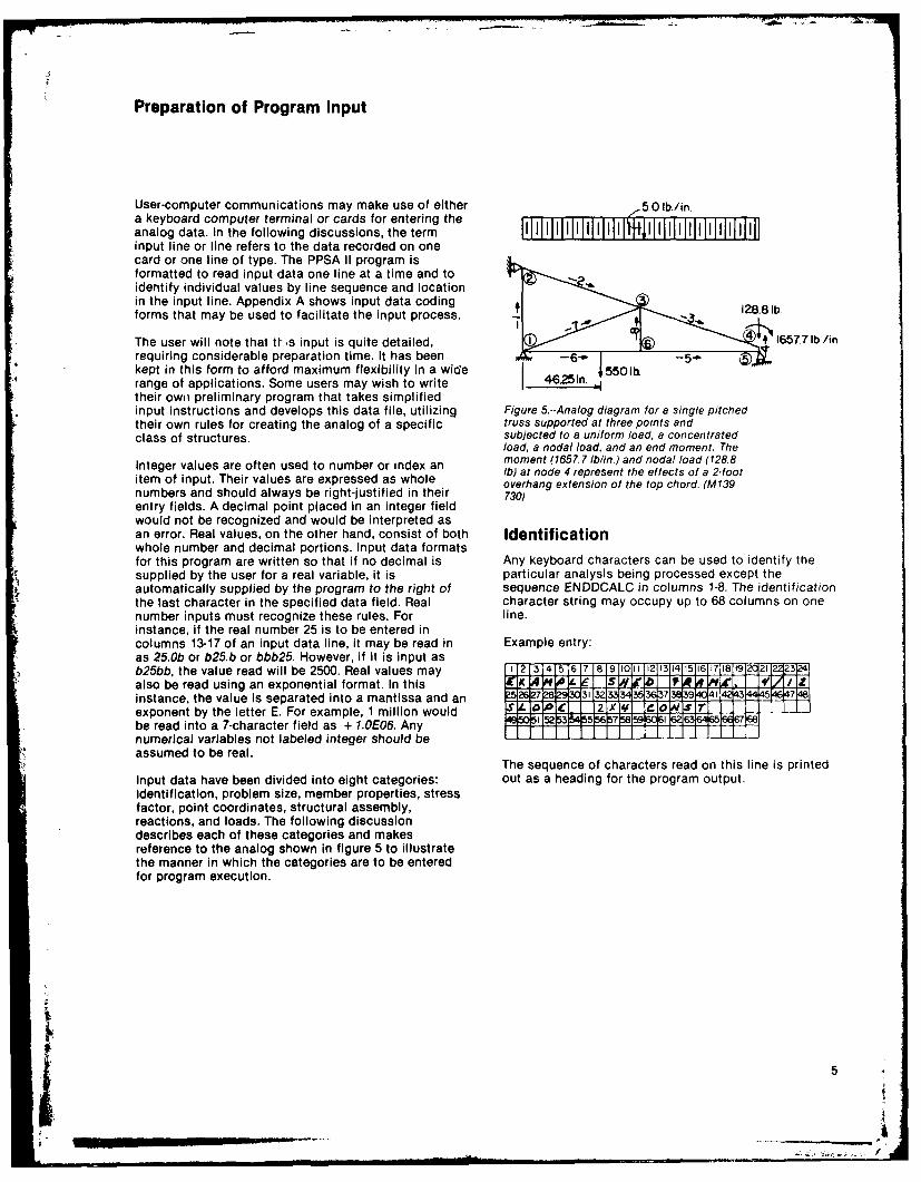
The user will note that tW-s input is quite detailed, 16577 lb./inrequiring considerable preparation time. It has beenkept in this form to afford maximum flexibility in a wide 46 5501hrange of applications. Some users may wish to write 4.5n ..
their own preliminary program that takes simplifiedinput instructions and develops this data file, utilizing Figure 5--Analog diagram for a single pitchedtheir own rules for creating the analog of a specific truss supported at three points andclass of structures. subjected to a uniform load, a concentrated
load, a nodal load, and an end moment. TheInteger values are often used to number or index an moment (1657.7 lb/in.) and nodal load (128.8itegerw Ib) at node 4 represent the effects of a 2-footitem of input. Their values are expressed as whole overhang extension of the top chord. (M139numbers and should always be right-justified in their 730)entry fields. A decimal point placed in an integer fieldwould not be recognized and would be interpreted asan error. Real values, on the other hand, consist of both Identificationwhole number and decimal portions. Input data formatsfor this program are written so that if no decimal is Any keyboard characters can be used to identify thesupplied by the user for a real variable, it is particular analysis being processed except theautomatically supplied by the program to the right of sequence ENDDCALC in columns 1-8. The identificationthe last character in the specified data field. Real character string may occupy up to 68 columns on onenumber inputs must recognize these rules. For line.instance, if the real number 25 is to be entered incolumns 13-17 of an input data line, it may be read in Example entry:as 25.Ob or b25.b or bbb25. However, if it is input asb25bb, the value read will be 2500. Real values may 121 1314 151,67118191221Jl23124also be read using an exponential format. In this X JA& L1 ] 4 P . I /1instance, the value is separated into a mantissa and an 15 l 3,132 33 35 3373894 43 44 s5exponent by the letter E. For example, 1 million would J1 Ijqltsrbe read into a 7-character field as + 1.0E06. Any
numerical variables not labeled integer should beassumed to be real.
The sequence of characters read on this line is printedInput data have been divided into eight categories: out as a heading for the program output.Identification, problem size, member properties, stressfactor, point coordinates, structural assembly,reactions, and loads. The following discussiondescribes each of these categories and makesreference to the analog shown in figure 5 to illustratethe manner in which the categories are to be enteredfor program execution.
S _ _ _ _ .. 5
Problem Size Member PropertiesThe Problem Size line tells the computer the size of the Member Property lines describe the memberstructure being analyzed, the amount of output wanted, mechanical properties, sizes, and type of use.and the number of load situations to be considered.
Line format:Line format:Columns 1-2--Integer: Member group number beginning
Columns 1-2--Integer: Number of points (NP) used in the with bl.Each variation in member size, strength, oranalog, type of use creates a so-called member group and
Columns 3-4--Integer: Number of members (NM) in the thus requires a separate input line.analog. Columns 3-7--Thickness, in inches, of the member in the
Columns 5-6--Integer: Number of Roll (NR) reactions direction perpendicular to the plane of the structure.used in the analog. Columns 8-12--Depth, in inches, in the plane of the
Columns 7-8--Integer: Number of Pin (NPIN) reactions in structure.the analog. Columns 13-18--MOE, in pounds per square inch, of the
Columns 9-10--Integer: Number of FIRL (NFIR) reactions member material. Because of the magnitude of thisused in the analog, number, all MOE values are read in using an ex-
Columns 11-12--Integer: Number of FIX (NFX) reactions ponential format. An MOE of 1,760,000 could be writ-used in the analog, ten 1.76 x 10⁸: The computer recognizes this number
Column 13 written as 1.76E6 in the six-column field.0 or blank = List all input (tables I-VI). Columns 19-22--Normal duration allowable bending1 = Do not list input. stress in pounds per square inch (ASIGM). This and
Column 14 the following two entries come from lumber grade0 or blank = List all output (tables VII-XII). stress tables such as are found in the NDS (NFPA1 = List only tables VII and VIII--reactions and 1982) and are entered as whole numbers with the
member end actions. decimal supplied by the machine at the right-hand2 = List only table IX--analysis. side of the field. When a special stress adjustment is3 = List only tables IX and X--interaction and shear pertinent to only one category of stress, the adjusted
stresses. value should be used in the appropriate field. An ex-4 = List only tables Xl and XIl--deformations and ample for bending stress is the 15 percent increase
displacements. for repetitive member use (table 4A of NDS). Since5 = List only tables IX-XII. this factor is applicable only to bending stress (Fb),
Columns 15-16--Integer: Number of load cases (NLOAD). the adjustment should be made prior to entry in thisIf only one load case is to be considered, this may be field. The program estimates this adjustment factorleft blank. The purpose of this input is to permit on the basis of the effective bending length overriderepeated analyses of a structural configuration under entry discussed later under Structural Assembly
different loads without the added time and expense input.
of reentering member and joint information andrecalculating the structural stiffness matrix. Subse- The ASIGM field is left blank if the member is fic-quent load cases operate at higher speed at a frac- titious and not subject to shear deflection. If sheartion of the computing time cost of the initial load deflection is to be included in a fictitious member,
case. any nonzero entry will suffice, although it is conve-Columns 17-18--Integer: Number of locations checked nient to use a number like 9,000, which is obviously
for stress and deformation along each member. if left not a wood stress value.
blank, 24 points will be checked along each member. olumns 23-26--Normal duration allowable compression
Example entry: stress, in pounds per square inch. This field is leftblank if the member is fictitious.
Columns 27-30--Normal duration allowable tensileZstress, in pounds per square inch. This field is left
NP i NM NR IiN N F1R NFX - - blank if the member is fictitious.l3145 6 78e 911i21314itl5 1617
4 16 t Zl I 1 I1J I
6t
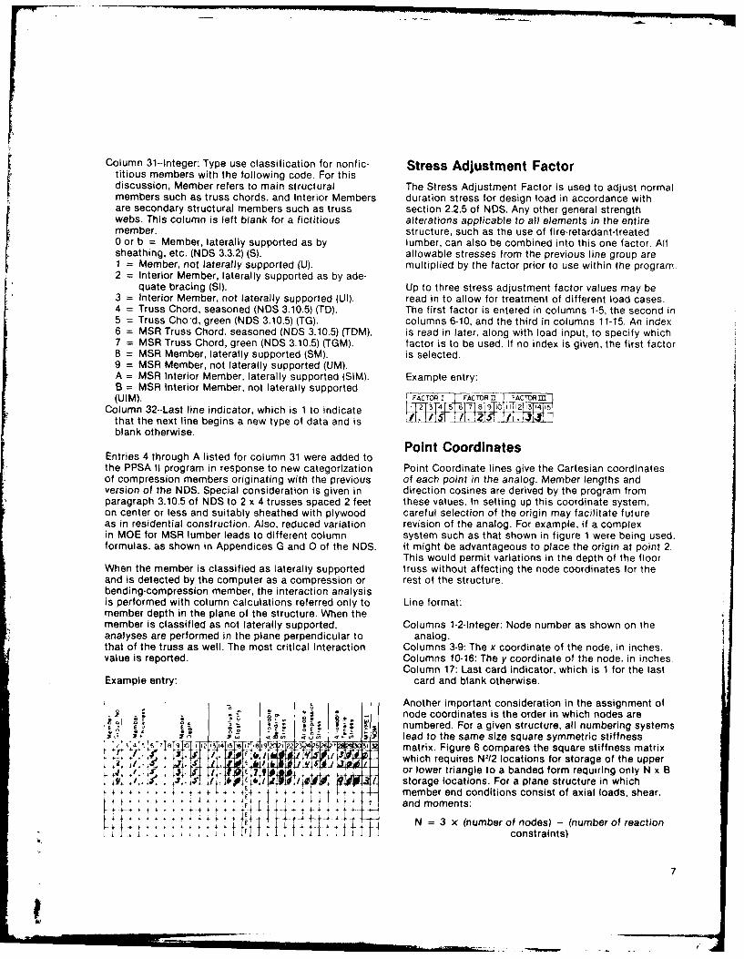
Column 31--Integer: Type use classification for nonfic- Stress Adjustment Factortitious members with the following code. For thisdiscussion, Member refers to main structural The Stress Adjustment Factor is used to adjust normalmembers such as truss chords, and Interior Members duration stress for design load in accordance withare secondary structural members such as truss section 2.2.5 of NDS. Any other general strengthwebs. This column is left blank for a fictitious alterations applicable to all elements in the entiremember. structure, such as the use of fire-retardant-treated0 or b = Member, laterally supported as by lumber, can also be combined into this one factor. Allsheathing, etc. (NDS 3.3.2) (S). allowable stresses from the previous line group areI = Member, not laterally supported (U). multiplied by the factor prior to use within the program.2 = Interior Member, laterally supported as by ade-
quate bracing (SI). Up to three stress adjustment factor values may be3 = Interior Member, not laterally supported (UI). read in to allow for treatment of different load cases.4 = Truss Chord, seasoned (NDS 3.10.5) (TD). The first factor is entered in columns 1-5. the second in5 = Truss Cho'd, green (NDS 3.10.5) (TG). columns 6-10, and the third in columns 11-15. An index6 = MSR Truss Chord, seasoned (NDS 3.10.5) (TDM). is read in later, along with load input, to specify which7 = MSR Truss Chord, green (NDS 3.10.5) (TGM). factor is to be used. If no index is given, the first factor8 = MSR Member, laterally supported (SM). is selected.9 = MSR Member, not laterally supported (UM).A = MSR Interior Member, laterally supported (SIM). Example entry:B = MSR Interior Member, not laterally supported(U IM). FACOR FCT -1 FCTR
Column 32--Last line indicator, which is 1 to indicate 12 1 1415
that the next line begins a new type of data and is L __
blank otherwise.Point Coordinates
Entries 4 through A listed for column 31 were added tothe PPSA II program in response to new categorization Point Coordinate lines give the Cartesian coordinatesof compression members originating with the previous of each point in the analog. Member lengths andversion of the NDS. Special consideration is given in direction cosines are derived by the program fromparagraph 3.10.5 of NDS to 2 x 4 trusses spaced 2 feet these values. In setting up this coordinate system,on center or less and suitably sheathed with plywood careful selection of the origin may facilitate futureas in residential construction. Also, reduced variation revision of the analog. For example, if a complexin MOE for MSR lumber leads to different column system such as that shown in figure 1 were being used.formulas, as shown in Appendices G and 0 of the NDS. it might be advantageous to place the origin at point 2.
This would permit variations in the depth of the floorWhen the member is classified as laterally supported truss without affecting the node coordinates for theand is detected by the computer as a compression or rest of the structure.bending-compression member, the interaction analysisis performed with column calculations referred only to Line format:member depth in the plane of the structure. When themember is classified as not laterally supported, Columns 1-2-Integer: Node number as shown on theanalyses are performed in the plane perpendicular to analog.that of the truss as well. The most critical interaction Columns 3-9: The x coordinate of the node, in inches.value is reported. Columns 10-16: The y coordinate of the node, in inches.
Column 17: Last card indicator, which is 1 for the lastExample entry: card and blank otherwise.
o Another important consideration in the assignment of- node coordinates is the order in which nodes are
S . numbered. For a given structure, all numbering systems•, .73 .- lead to the same size square symmetric stiffness
,-, - ,,, ,j? 3... matrix. Figure 6 compares the square stiffness matrixa, : 1-:. 1. ;which requires N12 locations for storage of the upper
S jE I 759 If or lower triangle to a banded form requiring only N x B+,i *f:;*.t ,, .* ,,v* +.1 storage locations. For a plane structure in which
f+ 4 member end conditions consist of axial loads, shear,+ . and moments:
4 Irt N = 3 x (number of nodes) - (number of reactionI I:::::. , . hut Iconstraints)
7
- .
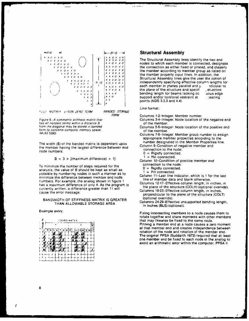
k-,--86 -1 Structural AssemblyX .X 0 A XV0 AX X X l
X x X 0 x X x o The Structural Assembly lines identify the two endt V 0 X X a x 0X x 0 nodes to which each member is connected, designate
x o xx X Ox A' the connection as either fixed or pinned, and classify" x o X x x X x 0 the member according to member group as listed on
X k 0 X X x A 0 X x X the member property input lines. In addition, theXA A0V V 0' x x A 0 x 0 Structural Assembly lines give the user the option of
A , x 0 , N5 X V X X A independently specifying effective column lengths forX X 0 X X 0 0 V X 0 V each member in planes parallel and p idicular to
X k x V x x x V x the plane of the structure and specif etectiveA T A X x X x x bending length for beams lacking cc uous edge
A x V Ix x 0 support and/or torsional restraint at .)earingX A points (NDS 3.3.3 and 4.4).
Line format:'JLL VfTR/X x -NON ZERO TEAM B4NOEO ST6rW4GE
f CRM Columns 1-2--Integer: Member number.Figure 6.--A symmetric stiffness matrix that Columns 3-4--Integer: Node location of the negative endhas all nonzero terms within a distance B of the member.from ihe diagonal may be stored in banded Columns 5-6--Integer: Node location of the positive endform to conserve computer memory space. of the member.(ML83 5590) Columns 7-8--Integer: Member group number to assign
appropriate member properties according to thenumber designated in the Member Properties line.
The width (B) of the banded matrix is dependent upon Column 9--Condition of negative member end
the member having the largest difference between end Conecon to h nenodenumbrs:connection to the node:
node numbers: 0 = Rigidly connected.
B = 3 x [(maximum difference) + 1]J 1 = Pin connected.
Column 10--Condition of positive member end
To minimize the number of steps required for the connection to the node:
analysis, the value of B should be kept as small as 0 = Rigidly connected.
possible by numbering nodes in such a manner as to 1 = Pin connected.
minimize the difference between member end node Column 11--Last line indicator, which is 1 for the last
numbers. For example, the analog shown in figure 1 line of member data and blank otherwise.
has a maximum difference of only 4. As the program is Columns 12-17--Effective column length, in inches. incurrently written. a difference greater than 11 will the plane of the structure (COLH) (optional override).cure ten a fere: gColumns 18-23--Effective column length, in inches,cause the error message: perpendicular to the plane of the structure (COLT)
BANDWIDTH OF STIFFNESS MATRIX IS GREATER (optional override).
THAN ALLOWABLE STORAGE AREA Columns 24-29--Effective unsupported bending length,in inches (BLE) (optional).
Example entry: Fixing intersecting members to a node causes them to
rotate together and share moments with other membersCOORDINATES that may likewise be fixed to the same node.
S -1Pinning a member end at a node causes a zero momentat that member end and creates independence between
Vt3-4456 7 8TTB910o-[,1 ,1 617T rotation of the node and rotation of the member end.The original PPSA (Suddarth 1972) required that at leastone member end be fixed to each node in the analog to
:ili$ A avoid an arithmetic error within the computer. PPSA II
8 a J Ad
8 Ii ~ I
01
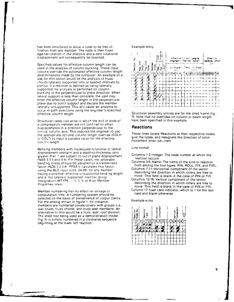
has been structured to allow a node to be tree of Example entry.fixation from any member. The node is then fixedagainst rotation in the analysis and a zero rotational ' z
displacement will consequently be reported. o Effecl,e ,CU.mn _ n's Effec?,e
iEngkneer C Gede Opbaw E.ndng _e 1
Specified values for effective column length can be c I
used in the analysis of column buckling. These input I n-Plr IPer l, Pontoptions override the autom ated effective colum n length _& 3 TZ
'Z 5 103t ,1,,. , ,ToT 2
determinations made by the computer. An example of a 4' J i ?T8 9 -- ..use for this option would be the analysis of truss --chords laterally supported only at spaced intervals by -- 4-4 -
purlins. If a member is defined as being laterally +.. .. .supported, no analysis is performed on column I _ ' _ -,Ibuckling in the perpendicular-to-plane direction. When , J - ilateral support is less than complete, the user may LJr _ -,enter the effective column length in the perpendicular .
- _ - - - .__ ,. __.. --
plane due to purlin support and declare the member +-laterally unsupported. This will cause an analysis to 4 4'44occur in both directions using the engineer's specifiedeffective column length. Structural assembly entries are for the shed frame (fig.
5). Note that no overrides on column or beam lengthStructural cases can arise in which the end or ends of have been specified in this example.a compression member are not confined to smalldisplacements in a direction perpendicular to the Reactionscritical column axis. This requires the engineer to usethe appropriate optional column length override (COLH These lines locate Reactions at their respective nodes.
or COLT) to input a suitable value for the eftective give the types, and designate the direction of roller
column length movement when per ,nent.
Bending members with inadequate rotational or lateral Line format:
displacement restraint and a depth-to-thickness ratiogreater than 1 are sublect to out-of-plane displacement Columns 1-2--nteger: The node number at which the
(NDS 3.3 3 and 4.41. For these cases, the allowable con reactinccurs.
bending stress should be adjusted by a slenderness Columns 3o6--Name: The name of the kind o reaction
factor (NDS 3 33.4). PPSA I1 calculates this factor, from among the four types: PIN, ROLL, FIX, and FIRL.
using the BLE input (cols 24-29). for any member Columns 7-11--Horizontal component of the vector
having a positive 'effective unsupported bending length' describing the direction in which rollers are free to
and a 'not laterally supported member group move. This field is blank in the case of PIN or FIX.
designation IMTYPE = 1.3.9. or B on Member Columns 12-16--Vertical component o! the vectorProperties lines) describing the direction in which rollers are free to
move. This field is blank in the case of PIN or FIX.Member numbering has no effect on storage or Column 17--Last card indicator, which is 1 for the lastcomputation time A numbering system should be card and blank otherwise.selected on the basis of convenience of output clarity.For the analog shown in figure 1. for instance. Example ehtry
members are numbered consecutively with groups (i.e.,wall studs, truss chords, and truss web members). An _E
alternative to this would be a floor, wall, roof division. Oa 9 oThe shed roof being used as a demonstration model , , E
(fig. 51 is simply numbered in a clockwise sequence j, 5 6 7 6 9ho , 45 i,
beginning at the lower left reaction.,6 89
.4-4 4 -
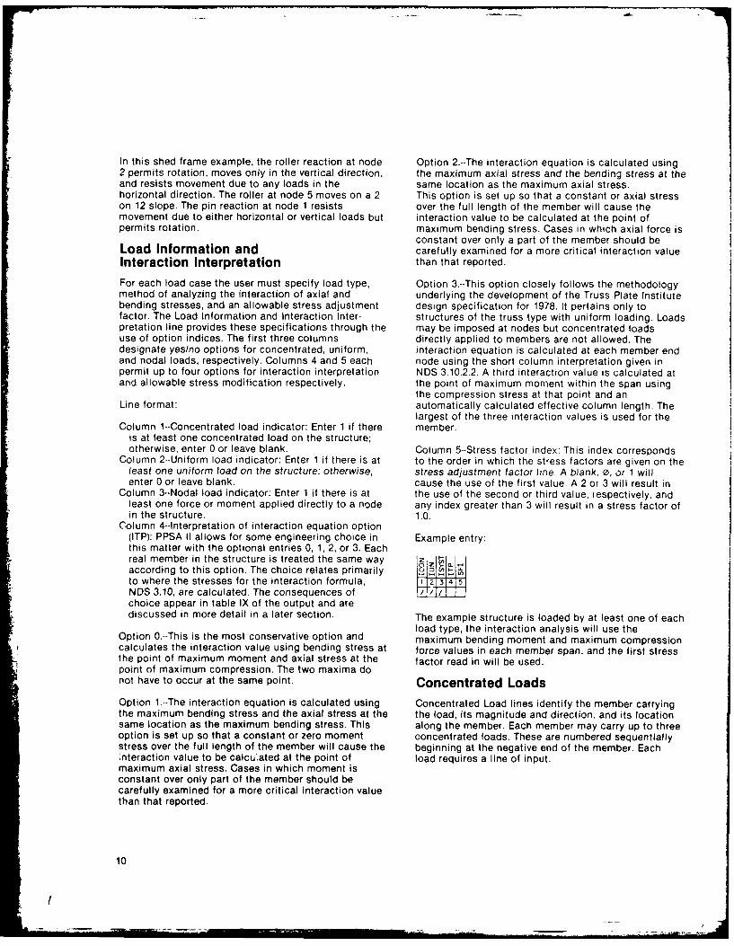
In this shed frame example, the roller reaction at node Option 2.--The interaction equation is calculated using2 permits rotation, moves only in the vertical direction, the maximum axial stress and the bending stress at theand resists movement due to any loads in the same location as the maximum axial stress.horizontal direction. The roller at node 5 moves on a 2 This option is set up so that a constant or axial stresson 12 slope. The pin reaction at node 1 resists over the full length of the member will cause themovement due to either horizontal or vertical loads but interaction value to be calculated at the point ofpermits rotation. maximum bending stress. Cases in which axial force is
constant over only a part of the member should beLoad Information and carefully examined for a more critical interaction valueInteraction Interpretation than that reported.
For each load case the user must specify load type, Option 3.--This option closely follows the methodologymethod of analyzing the interaction of axial and underlying the development of the Truss Plate Institutebending stresses, and an allowable stress adjustment design specification for 1978. It pertains only tofactor. The Load Information and Interaction Inter- structures of the truss type with uniform loading. Loadspretation line provides these specifications through the may be imposed at nodes but concentrated loadsuse of option indices. The first three columns directly applied to members are not allowed. Thedesignate yes/no options for concentrated, uniform, interaction equation is calculated at each member endand nodal loads, respectively. Columns 4 and 5 each node using the short column interpretation given inpermit up to four options for interaction interpretation NDS 3.10.2.2. A third interaction value is calculated atand allowable stress modification respectively, the point of maximum moment within the span using
the compression stress at that point and anLine format: automatically calculated effective column length. The
largest of the three interaction values is used for theColumn 1--Concentrated load indicator: Enter 1 if there member.
is at least one concentrated load on the structure;otherwise, enter 0 or leave blank. Column 5--Stress factor index: This index corresponds
Column 2--Uniform load indicator: Enter 1 if there is at to the order in which the stress factors are given on theleast one uniform load on the structure; otherwise, stress adjustment factor line. A blank, 0, or 1 willenter 0 or leave blank. cause the use of the first value. A 2 or 3 will result in
Column 3--Nodal load indicator: Enter 1 if there is at the use of the second or third value, respectively, andleast one force or moment applied directly to a node any index greater than 3 will result in a stress factor ofin the structure. 1.0.
Column 4--Interpretation of interaction equation option(ITP): PPSA II allows for some engineering choice in Example entry:this matter with the optional entries 0, 1, 2, or 3. Eachreal member in the structure is treated the same way I jIIaccording to this option, The choice relates primarilyto where the stresses for the interaction formula,NDS 3.10, are calculated. The consequences ofchoice appear in table IX of the output and arediscussed in more detail in a later section. The example structure is loaded by at least one of each
load type, the interaction analysis will use theOption 0.--This is the most conservative option and maximum bending moment and maximum compressioncalculates the interaction value using bending stress at force values in each member span, and the first stressthe point of maximum moment and axial stress at the factor read in will be used.point of maximum compression. The two maxima donot have to occur at the same point. Concentrated LoadsOption 1--The interaction equation is calculated using Concentrated Load lines identify the member carryingthe maximum bending stress and the axial stress at the the load, its magnitude and direction, and its locationsame location as the maximum bending stress. This along the member. Each member may carry up to threeoption is set up so that a constant or zero moment concentrated loads. These are numbered sequentiallystress over the full length of the member will cause the beginning at the negative end of the member. Each:nteraction value to be calcu'ated at the point of load requires a line of input.maximum axial stress. Cases in which moment isconstant over only part of the member should becarefully examined for a more critical interaction valuethan that reported.
10
I
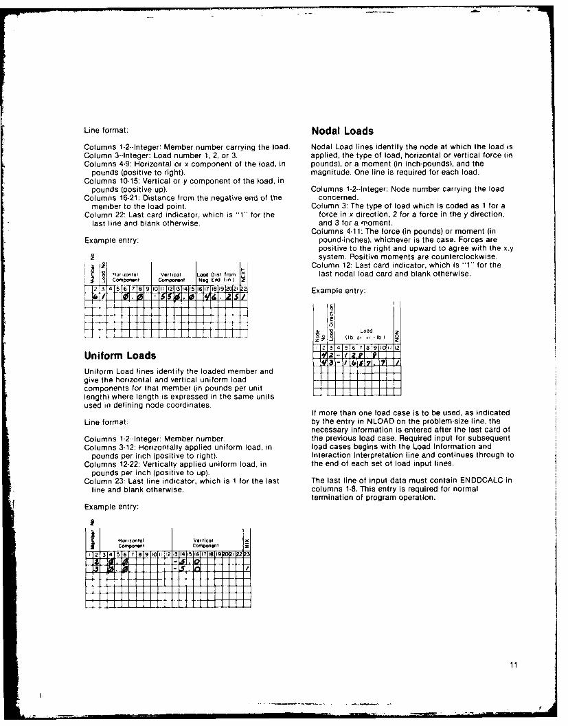
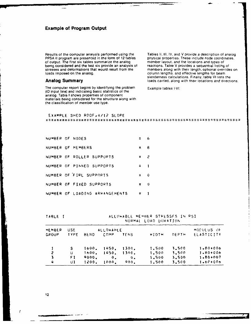
Line format: Nodal LoadsColumns 1-2--Integer: Member number carrying the load. Nodal Load lines identify the node at which the load isColumn 3--Integer: Load number 1, 2, or 3. applied, the type of load, horizontal or vertical force (inColumns 4-9: Horizontal or x component of the load, in pounds), or a moment (in inch-pounds), and the
pounds (positive to right), magnitude. One line is required for each load.Columns 10-15: Vertical or y component of the load, in
pounds (positive up). Columns 1-2--Integer: Node number carrying the loadColumns 16-21: Distance from the negative end of the concerned.
member to the load point. Column 3: The type of load which is coded as 1 for aColumn 22: Last card indicator, which is 1" for the force in x direction, 2 for a force in the y direction,
last line and blank otherwise. and 3 for a moment.Columns 4-11: The force (in pounds) or moment (in
Example entry: pound-inches), whichever is the case. Forces arepositive to the right and upward to agree with the x.y
Z_ system. Positive moments are counterclockwise.
SI Column 12: Last card indicator, which is "1" for ther I Ho,,zontai Vertical iood ist from last nodal load card and blank otherwise.
S Componen Componion Nag End (in)
2 3 45617 89 10111112113114115 16 17 18 19 122 2. Example entry:
F -tt1 VLoadj (Ib 1
lb)
1F213 4 5 6 7 8T91I011 12
Uniform Loads -
Uniform Load lines identify the loaded member and 4]give the horizontal and vertical uniform loadcomponents for that member (in pounds per unitlength) where length is expressed in the same units
used in defining node coordinates.If more than one load case is to be used, as indicated
Line format: by the entry in NLOAD on the problem-size line, thenecessary information is entered after the last card of
Columns 1-2--Integer: Member number. the previous load case. Required input for subsequentColumns 3-12: Horizontally applied uniform load, in load cases begins with the Load Information and
pounds per inch (positive to right). Interaction Interpretation line and continues through toColumns 12-22: Vertically applied uniform load, in the end of each set of load input lines.
pounds per inch (positive to up).Column 23: Last line indicator, which is 1 for the last The last line of input data must contain ENDDCALC in
line and blank otherwise. columns 1-8. This entry is required for normaltermination of program operation.
Example entry:
2] 314516171619 10C 11 12 13 14 15 16 17 18 1912b1 22.22
Sl. 10 1 11
Example of Program Output
Results of the computer analysis performed using the Tables II, Ill, IV, and V provide a description of analogPPSA II program are presented in the form of 12 tables physical properties. These include node coordinates.of output. The first six tables summarize the analog member layout, and the locations and types ofbeing considered and the last six provide an analysis of reactions. Table V provides a sequential listing ofstresses and deformations that would result from the members along with their length, optional overrides onloads imposed on the analog, column lengths, and effective lengths for beam
slenderness calculations. Finally, table VI lists the
Analog Summary loads carried, along with their locations and directions.
The computer report begins by identifying the problem Example tables -VI:(ID input line) and indicating basic statistics of the
analog. Table I shows properties of componentmaterials being considered for the structure along withthe classification of member use type.
EXAMPLE SHED ROOF,U/t2 SLOPE
NUMBER OF NODES 6
NUMBER OF MEMBERS 8
NUMBER OF ROLLER SUPPORTS 2
NUMBER OF PINNED SUPPORTS I
NUMBER OF FIRL SUPP(IRTS 0
NUMBER OF FIXED SUPPORTS 0
NUMBER OF LOADING ARPANGEMENTS 1
TABLE I ALL( .ABLE MEMtHER STRESSFS IN PSINORMAL LOAD DIJRATION
MEMBER USE ALLOWARLE MOrULUS OF
GROUP TYPE BEND CRMP TENS WIDTH DEPTH ELASTICITY
I S bO00. 1l450. 1300. 1.500 ".500 1.80+00
2 U 1thO0, 1450, 1300. 1.500 3,500 1.80+00b
3 FI QOOO. 0. 0, 1.500 3.500 1.80+007
4 u1 1200. 1000. Qoo, 1,500 3.500 1.60+00b
12
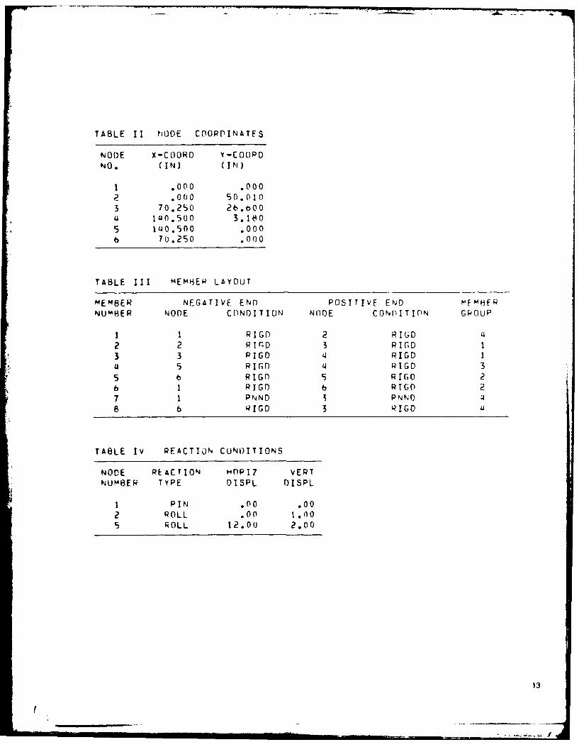
TABLE 11 NUDE COORPINATFS
NODE X-COORD Y-COOPD
NO. (IN) (pl)
I .0o0 .0002 oo0 50.010
3 70.2S0 26.bO0(1 1un.500 3.11 O
5 1uo.500 .000b 70.250 oo00
TABLE III mEm6ER LAYOUT
MEMBER NEGATIVE END POSITIVE END MFmHFPNUM*BER NODE CONDITION NnDE CONPITION GkOUP
I 1 R I GD 2 RI16D 142 2 R I G 3 R I GD I3 3 PIGD 41 RIGD 1
'35 R IGD '3 RIGO 35 b RIGn 5 R IG 2h I PRI GD b RGo 27 1 PNND 3PNND £3
8 b41G RIG iC '
TABLE IV PEACTION CUNIOITIONS
NODE REACTION Hn~pIZ VEPTNUMBER TYPE DISPL DISPL
1 P IN .00 .002ROLL .00 1.00
5 ROLL 12.00 2.00
13
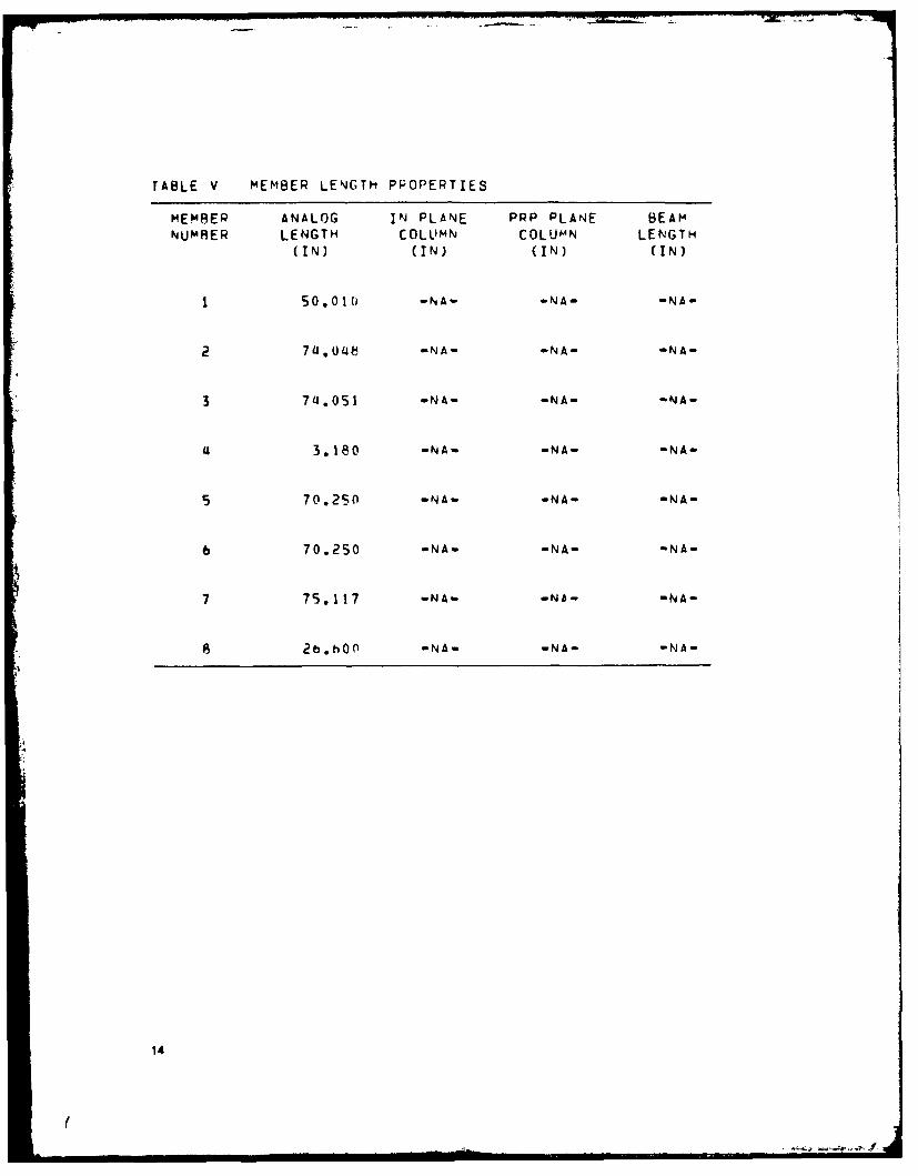
TABLE V MEMBER LENGTH PPOPERTIES
MEMBER ANALOG IN PLANE PRP PLANE BEAM
NUMRER LENGTH COLUMN COLUMN LENGTH(IN) (IN) (IN) (IN)
1 50.010 -NA- -NA- -NA-
2 744 -NA- -NA- -NA-
3 7,.051 -NA- -NA- -NA-
3.180 -NA- -NA- -NA-
5 70.250 -NA- -NA- -NA-
6 70.250 -NA- -NA- -NA-
7 75.117 -NAw -Nb- -NA-
8 2b.bo0 -NA- -NA- -NA-
14
I,
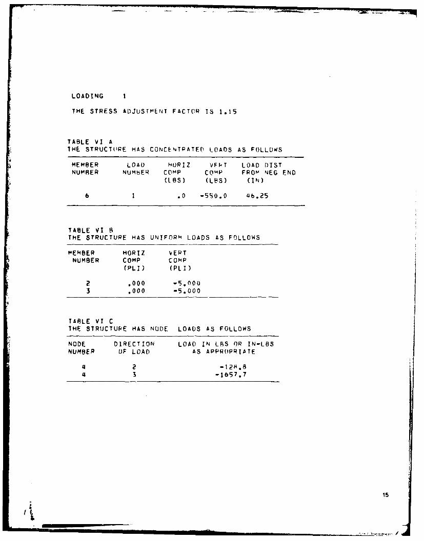
LOADING I
THE STRESS ADJUSTMEN4T FACTOR IS 1.15
TABLE VI ATHE STRUCTURE HAS CONCENTPATE LOADS AS FOLLOWS
MEMBER LOAD HORIZ VFI-T LOAD DISTNUMBER NUMbER COMP Comp FROM NEG END
(IBS) (LBS) (IN)
6 1 .0 -5S0.0 46.25
TABLE VI BTHE STRUCTURE HAS UNIFORM LOADS AS FOLLOWS
MEMBER HORIZ VEPTNUMBER COMP COMP
(PLI) (PLI)
2 ,000 -5,0003 .000 -5.000
TABLE VI CTHE STRUCTURE HAS NODE LOADS AS FOLLOWS
NODE DIRECTION LOAD IN LBS OR IN-LBSNUMBER OF LOAD AS APPROPRIATE
2 -12 8
4 3 -1657.7
15
A _______
,£
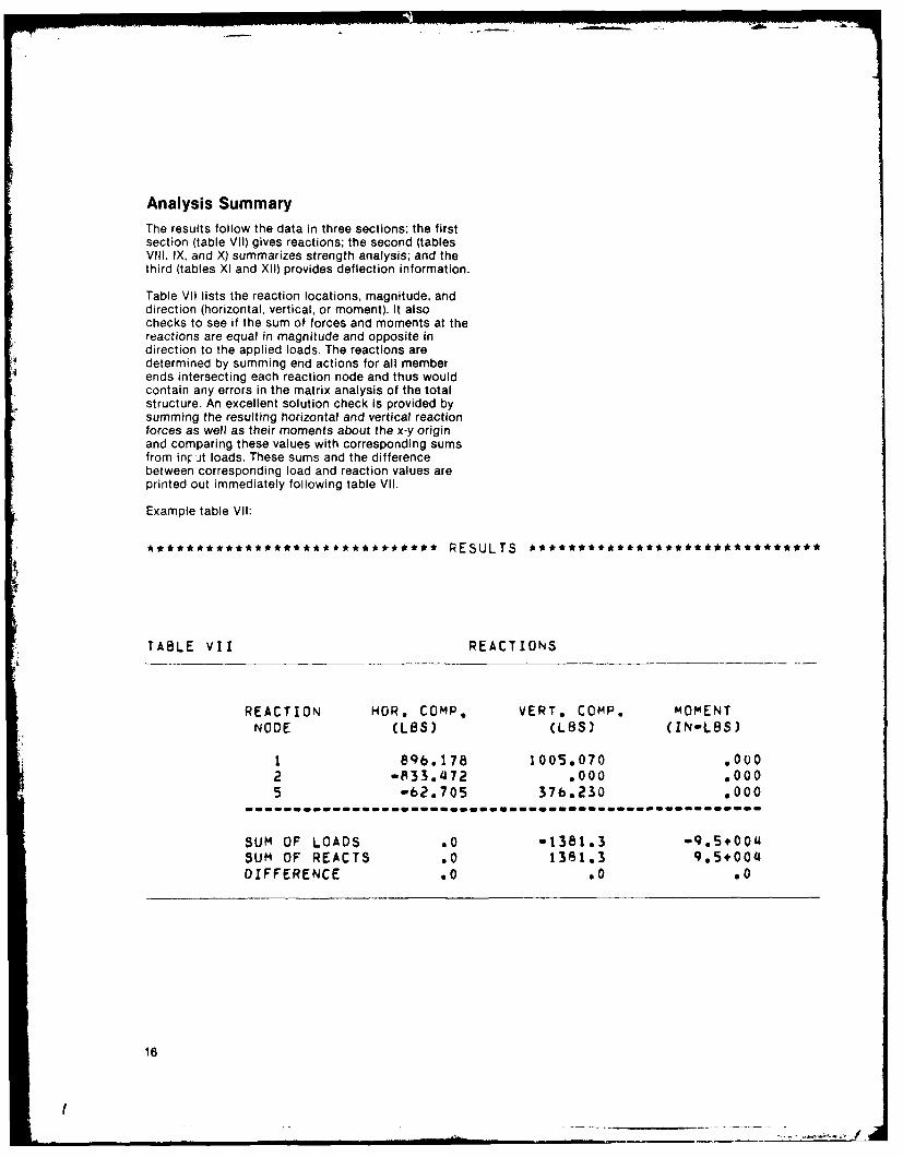
Analysis SummaryThe results follow the data in three sections; the firstsection (table VII) gives reactions; the second (tablesVili, IX, and X) summarizes strength analysis; and thethird (tables Xl and XII) provides deflection information.
Table VII lists the reaction locations, magnitude, anddirection (horizontal, vertical, or moment). It alsochecks to see if the sum of forces and moments at thereactions are equal in magnitude and opposite indirection to the applied loads. The reactions aredetermined by summing end actions for all memberends intersecting each reaction node and thus wouldcontain any errors in the matrix analysis of the totalstructure. An excellent solution check is provided bysumming the resulting horizontal and vertical reactionforces as well as their moments about the x-y originand comparing these values with corresponding sumsfrom inr Jt loads. These sums and the differencebetween corresponding load and reaction values areprinted out immediately following table VII.
Example table VII:
***************************** ~ESULTS ****************************
TABLE VII REACTIONS
REACTION HOR. COMP. VERT. COMP. MOMENT
NODE (LBS) (LBS) (IN-LBS)
1 896.178 1005.070 ,0002 -833.a72 .000 .000
5 -62.705 376.230 .000--i------ ---e-epl------i-e en - cone - -o e W nnnflnnflfl -
SUM OF LOADS .0 -1381.3 -9.5+O00SUM OF REACTS .0 1381.3 9.5+00DIFFERENCE .0 .0 .0
16
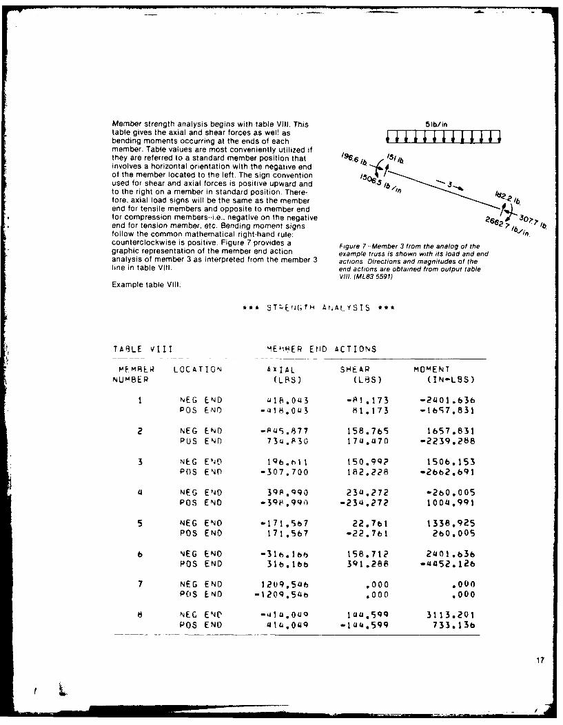
Member strength analysis begins with table VIII. This 51b/intable gives the axial and shear forces as wel! as ____________________________
bending moments occurring at the ends of eachmember. Table values are most conveniently utilized ifthey are referred to a standard member position that 196"6 .involves a horizontal orientation with the negative endof the member located to the left. The sign conventionused for shear and axial forces is positive upward and i5/to the right on a member in standard position. There-fore, axial load signs will be the same as the memberend for tensile members and opposite to member endfor compression members--i.e., negative on the negative 0?end for tension member, etc. Bending moment signs 6 ??1ji ?b
follow the common mathematical right-hand rule:counterclockwise is positive. Figure 7 provides a Figure 7 --Member 3 from the analog of thegraphic representation of the member end action example truss is shown with its load and endanalysis of member 3 as interpreted from the member 3 actions. Directions and magnitudes of theline in table VIII. end actions are obtained from output table
VIII (ML83 5591)Example table VIII:
*** STLEriGjTH ArALYSIS ***
TABLE VIII 4E IHER END ACTIONS
MF MIER LOCATION AXIAL SHEAR MOMENT
NUMBER (L0S) (LBS) (IN-LBS)
I NEG END J18.043 -PI.173 -2401.636POS END -418.043 81.173 -t657,831
2 NEG END -P45.877 158.765 1657.831PUS END 73a.P30 174U70 -2239.288
3 NEG END Iqb.,ll 150.99? 1506.153POS END -307.700 182.2268 -2662.691
4 NEG END 39P.qg9 234.272 -2b0.005
POS END -39FP*qo -234.272 1004.991
5 NEG END -171.5b7 22.7b1 1338,925POS END 171.567 -22.71 2b0.005
6 NEG END -31.16b 158.712 2401.b3b
P0S END 31b.1b 391.288 -44152.126
7 NEG END 1209.5L6 .000 .000
POS END -120q.54b .000 .000
8 NEC END -,41LjOIQ ILI.sqq 3113.201PO END 41t J,O4q -1I,.599 733.136
17
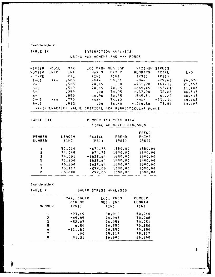
Table IX of the output gives the results of the Stresses reported in the table are the values requiredinteraction analysis. This analysis is dependent upon for the interaction option selected. They have algebraicthe member type, the loads it carries, its length-to- signs following the convention that axial tension isdepth ratios in or normal to the plane of the structure, positive and bending is positive when the tensile stressand the interaction analysis option (ITP) chosen on the is along the bottom edge of a member placed inLoad Information and Interaction Interpretation input standard position (horizontal with the negative end toline, the left).
The first three columns provide preliminary information. Table IXA has been included to give supplementaryColumn 1 identifies the member by its number and information including analog length and the finalgroup classification. Column 2 provides space for a adjusted allowable stresses used in the calculation offootnote reference if additional information is needed the combined stress index reported in table IX.to evaluate member design. The third column, labeledMAX INT VAL, gives the maximum value of the Table X reports maximum shear stress in each memberinteraction equation (combined stress index) within the from analyses made at the same points where bendingmember if both axial and bending stresses are present, and axial stresses have been determined, If the sameIf only axial or bending stress is present, the maximum is repeated, the location reported is thatinteraction column contains the ratio of actual stress nearest the positive end of the member.to allowable stress. The interaction concept is treatedin NDS 3.10 and is discussed in more detail in thefollowing section.
To find the maximum interaction value and themaximum shear stresses, bending, axial, and shearstresses are calculated at equally spaced locationsalong the length of each nonfictitious member. Thenumber of locations analyzed is determined by thevalue read into columns 15-16 of the Problem Size inputline. The input default in this case results in analysis at24 locations. Maximum values along with theirlocations are then printed out in tables IX and X of theoutput report. If a maximum stress value occurs morethan once, the location reported is usually that nearestthe positive end of the member.
The designer will note that many useful facts can bederived from table IX. For instance, the member 6portion of the lower chord (fig. 2) is more heavilyloaded, having an interaction value of 0.88 (table IX). Inthe upper chord, on the other hand, members 2 and 3have relatively low interaction values--0.491 and0.509--suggesting that a lower quality lumber may beused at these locations.
Footnotes such as that referenced for member 7 alsoprovide additional information. In the case of member7. the footnote tells the user that the critical stresscase occurs perpendicular to the plane of the structure.
18
Example table IX:
TABLE IX INTERACTION ANALYSIS
USING MAX MOMENT AND MAX FORCE
mEMBER ADON;L MAX LOC FROM NEf, END MAXIhUM STRESS
NUMBER INFL) INT MAX M MAX P HENOING AXIAL L/D- TYPE VAL (IN) (IN) (PSI) (PSI)I-UI *** b8b -NA- 50.01 -NA- -79.63 26.b722-3 .5(9 7 a.05 .00 -731.20 161.12 21.1573-S ,50q 7L.05 7j .05 -869.45 -58.b 11.005-u .259 .00 7.25 -437.20 32.68 ub.Q3b-U ,880 4UA.Qb 70.?5 1545.81 0. 22 Lbb.t33
7-UI *** ,770 -NA- 75.12 -NA- -230.39 ao.Ob38-U. ,813 .00 2b.hO -I01b.5b 78.87 la.1E7
***INTERACTION vALUE CRITICAL FOR PERPENdICULAR PLANE
TABLE IXA MEMPER AA:ALYSIS DATA
FINAL ADJUSTED STRESSES
FBENDMEMBER LENGTH FAXIAL FBEND PRIMENUMBER (IN) (PSI) (PSI) (PSI)
1 50.010 -b74.73 1380.00 1380.002 74.048 674.73 18'0.00 180,003 74.051 -1627.b 1bo0.00 18u0,005 70.250 1627.b 1 10.00 1840100b 70.250 1627.bi 1840.00 1840.007 75.117 -2q9.Ob 1380.00 1380.008 2b.bO0 299.06 1380.00 1380.00
Example table X:
TABLE X SHEAR STRESS ANALYSIS
MAX, SHEAR LOC. FROM MEMBER
STRESS NEG. END LENGTH
MEMBER (PSI) (IN) (IN)
1 -23.19 50.010 50.0102 -49.85 74.048 74.0483 -52.07 74.051 74.0515 b.50 70,250 70.2506 -111.80 70,290 70.2507 100 75,117 75.1178 41.31 2bbO0 26.600
19
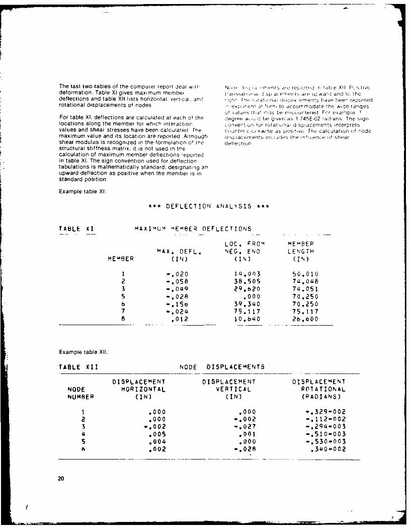
The last two tables of the computer report deal with ,i, r erijs ie repo ,nrtd ir, tibie X1i Psiti,,odeformation. Table Xl gives maximum member tlitr iid. Jispiat enents are upward and 1c, !hedeflections and table XII lists horizontal, vertical, and rtght The ,t ali(,nai displa rements hadve been reportedrotational displacements of nodes . egrn.l torn, to accommodate Ine wide ranges
I vdtlue5 lnaI ray bie ericountered For evample. 1For table Xl, deflections are calculated at each of the degree WOU1j0 be given as 1 745E-02 radians The signlocations along the member for which interaction convention tot rotational dispiacements interpretsvalues and shear stresses have been calculated The counter clockwise as positive The calculation of nodemaximum value and its location are reported Although dtspiacements includes the nlienCe of shearshear modulus is recognized in the formulation of the deflectionstructural stiffness matrix, it is not used in thecalculation of maximum member deflections reportedin table X1. The sign convention used for deflectiontabulations is mathematically standard, designating anupward deflection as positive when the member is instandard position.
Example table Xl:
*** DEFLECTION ANALYSIS *tt
TABLE XI MAXIMUM MEMBER DEFLECTIONS
LOC. FROM MEMBEPMAX. DEFL. NEG. END LENGTH
MEMBER (IN) (IN) (IN)
1 -. 020 14.003 50.0102 -. 058 38.505 74,0483 -. 049 2Q.620 74.0515 -. 028 .000 70.250b -. 15b 39.340 70.2507 -. 024 75.117 75.1178 .012 10.b640 26.bO0
Example table XI:
TABLE XII NODE DISPLACEMENTS
DISPLACEMENT DISPLACEMENT DISPLACEMENT
NODE HORIZONTAL VERTICAL ROTATIONALNUMBER (IN) (IN) (RADIANS)
1 .000 .000 -. 329-002
2 .000 -. 002 -. 112-0023 .002 -. 027 -. 294-003
.005 .001 -. 510-0035 .004 .000 -.530-003
.002 -. 028 .340-002
20
I-- a
Significance of Output in Table IX
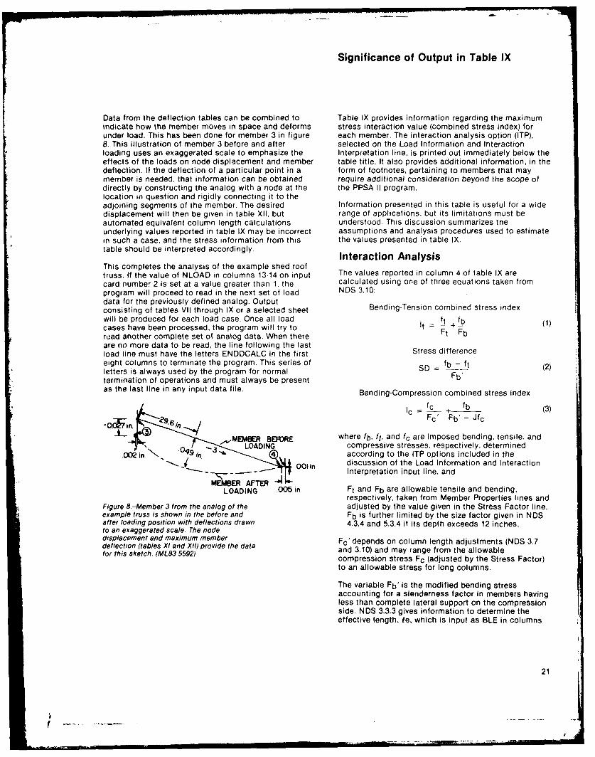
Data from the deflection tables can be combined to Table IX provides information regarding the maximumindicate how the member moves in space and deforms stress interaction value (combined stress index) forunder load. This has been done for member 3 in figure each member. The interaction analysis option (ITP),8. This illustration of member 3 before and after selected on the Load Information and Interactionloading uses an exaggerated scale to emphasize the Interpretation line, is printed out immediately below theeffects of the loads on node displacement and member table title. It also provides additional information, in thedeflection. If the deflection of a particular point in a form of footnotes, pertaining to members that maymember is needed, that information can be obtained require additional consideration beyond the scope ofdirectly by constructing the analog with a node at the the PPSA II program,location in question and rigidly connecting it to theadjoining segments of the member. The desired Information presented in this table is useful for a widedisplacement will then be given in table XII, but range of applications, but its limitations must beautomated equivalent column length calculations understood. This discussion summarizes tneunderlying values reported in table IX may be incorrect assumptions and analysis procedures used to estimatein such a case, and the stress information from this the values presented in table IX.table should be interpreted accordingly. Interaction AnalysisThis completes the analysis of the example shed rooftruss. If the value of NLOAD in columns 13-14 on input The values reported in column 4 of table IX arecard number 2 is set at a value greater than 1. the calculated using one of three equations taken fromprogram will proceed to read in the next set of load NDS 3.10:
data for the previously defined analog. Outputconsisting of tables VII through IX or a selected sheet Bending-Tension combined stress index
will be produced for each load case. Once all load ft fbcases have been processed, the program will try to It = ft + fb (1)road another complete set of analog data. When there Ft Fbare no more data to be read, the line following the lastload line must have the letters ENDDCALC in the first Stress difference
eight columns to terminate the program. This series of fb - ftletters is always used by the program for normal SD - b(2)termination of operations and must always be present F'as the last line in any input data file. Bending-Compression combined stress index
I _f_ + (3)Fc' Fb'- Jfc
MEMBER BEFORE where fb, ft, and fc are imposed bending, tensile, and-. LOADING compressive stresses, respectively, determined
.002in. 9 i according to the ITP options included in thediscussion of the Load Information and Interaction
O-- - 1 Interpretation input line, and
LOADING 005 in Ft and Fb are allowable tensile and bending,respectively, taken from Member Properties lines and
Figure 8--Member 3 from the analog of the adjusted by the value given in the Stress Factor line.example truss is shown in the before and Fb is further limited by the size factor given in NDSafter loading position with deflections drawn 4.3.4 and 5.3.4 if its depth exceeds 12 inches.to an exaggerated scale. The nodedisplacement and maximum member Fc'depends on column length adjustments (NDS 3.7deflection (tables Xl and XII) provide the data and 3.10) and may range from the allowablefor this sketch. (ML83 5592) compression stress Fc (adjusted by the Stress Factor)
to an allowable stress for long columns.
The variable Fb' is the modified bending stressaccounting for a slenderness factor in members havingless than complete lateral support on the compressionside. NDS 3.3.3 gives information to determine theeffective length. le, which is input as BLE in columns
21
24-29 of the Structural Assembly lines. Fb' may be A value for effective column length may also be neededequal to or less than Fb depending on the value of the perpendicular to the plane of the structure. If theeffective length, beam cross-sectional dimensions, and r. !mber is declared laterally supported, this columnMOE. A further requirement is that Fb'determined in length is automatically set at 11 (short category). Ifthis manner is also limited not to exceed Fb adjusted COLT in the Structural Assembly input for a laterallyby the size factor given in NDS 4.3.4 and 5.3.4. This is unsupported member is given a nonzero value, it isautomated within the program utilizing the inputs of used for the effective length in the perpendicular plane.member width, depth, and BLE. An appropriate value of Otherwise. the analysis of a laterally unsupportedFb' is produced for use in equations (2) and (3). If no member will use the analog length of a Member or 0.8value is entered for BLE, it is taken as zero. times the analog length of an Interior Member.
The variable J (NDS 3.10.2) is an interpolation value PPSA II can perform analyses of a wide variety of planeused to modify equation (3) for intermediate columns. structures providing useful values of member endIntermediate columns have lid ratios between 11 and k. actions and displacements but it cannct detect, withinin which k is the transition ratio between intermediate itself, cases in which the automated treatment, ofand long columns (NDS 3.10.5). Within this range. J effective member length are inappropriate. This isvaries as a linear function of f/d ratio from zero for particularly the case when effective member lengthsshort columns (lid < 11) to 1 for long columns (lid > k) should be longer than the analog member length. In(NDS 3.7, 3.10.5 and appendix G). such cases the user must supply suitable estimates of
effective length through the use of COLH and COLT iftable IX values are to be utilized.
effective column length Lateral Support of a MemberThe effective column length, as defined in NDtS
appendix N, is the distance between two points along Lateral support conditions can affect the analysis ofthe length of a compression member between which it any load-carrying member. It is thus important that theis assumed to buckle in the shape of a sine wave. lateral support of members be given careful attention in
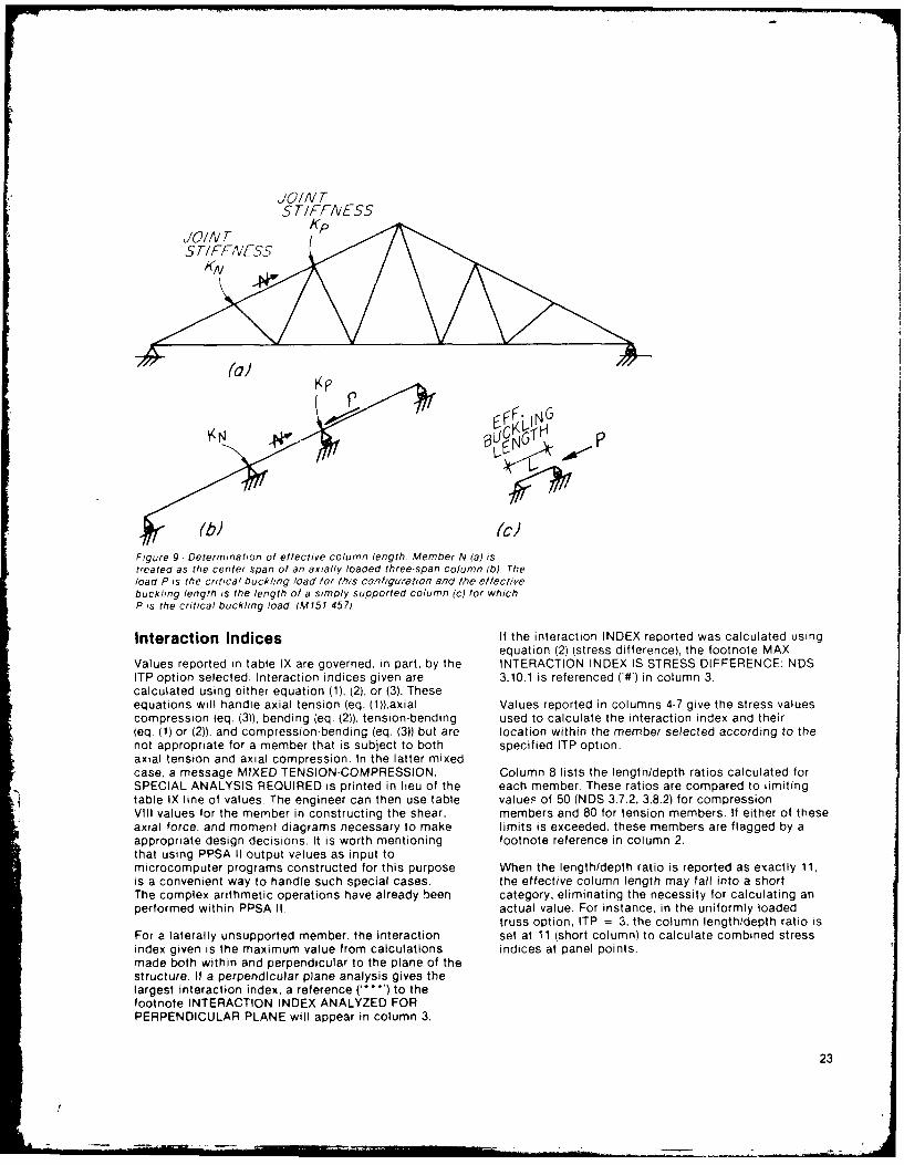
the column 31 entry in the Member Properties lines.A value for effective column length is needed in the This entry, labeled MTYPE1, offers 10 options.plane of the structures for all members subjected tocompression stress. It may be supplied as COLH in the The classification "Member" pertains to a mainStructural Assembly input by the user. If COLH is member in the structure such as a truss chord. It willentered as zero or blank, an automated procedure likely carry primary bending loads and will often bedetermines an effective column length limited to the framed as co.'inuing through a joint. An 'Interioraralog length of a Member or 0.8 times the analog Member' is secondary in the structure such as a trusslength of an Interior Member. The procedure assumes web framing into a chord. It will likely not carry primarythat the member ends are constrained against bending loads and. since it is usually jointed to ansignificant translational displacement so as to restrict edge of a member, will often have a longer analogthe effective column length within the analog member length than its actual lengthlength. Truss chord and web members usually fall intothis category. The method deals with each compression MTYPE1 classes 0 through 3 relate to visually gradedmember in the example fashion given for member N in lumber or any other prismatic wood member that wouldfigure 9. The location of N within the structure is require the use of column formulae as given in NDS 3 7shown in figure 9a along with its end rotational and beam slenderness factors as given in NDS 3 3 3stiffnesses, KN and Kp, which are quantities MTYPE1 classes 8 through B are similar but pertain todetermined within the matrix structural analysis. An MSR and herein use column formulae as given in NDSequivalent beam structure on one pin and three roller G 9 and beam slenderness formulae as given in NDSsupports places member N in a similar end restraint 0 6 MTYPE1 classes 4 through 7 are for a specialcondition (fig. 9b). The values KN and Kp are duplicated class of trusses as given in NDS 3.10.5. Of all of theseby suitable lengths for the end spans. An axial load, P, MTYPE1 classes, 1, 3. 9, and B are not laterallyis placed at the roller end of N acting against the pin supported These may require entry of effective lengthsupport at its other end. A stability analysis of the BLE in columns 24-29 of the Structural Assembly linesfigure 9b structure yields the buckling load. P. Finally,a simple column is created (fig. 9c) of such length. L.that P is the buckling load. L is then utilized as theeffective column length for in-plane analysis ofmember N.
22
(
JO/N T5 TIFFIVESS1/0//V TKp
STIFFNESS /\
(Ga)
(b) ('c)
Figure 9 Determination of effective column length. Member N (a) istreated as the center span of an axially loaded three-span column (b), Thetoad( P is the criticae buckling load lor this configura/ron and the eflectivebuckling length is the length of a simply supported column (c) for whichP is the critical buckling load. (M151 457)
Interaction Indices If the interaction INDEX reported was calculated usingequation (2) (stress difference), the footnote MAX
Values reported in table IX are governed, in part, by the INTERACTION INDEX IS STRESS DIFFERENCE: NDSITP option selected. Interaction indices given are 3.10.1 is referenced ('#) in column 3.calculated using either equation (1). (2), or (3). Theseequations will handle axial tension (eq. (1)),axial Values reported in columns 4-7 give the stress valuescompression (eq. (3)), bending (eq. (2)), tension-bending used to calculate the interaction index and their(eq. (1) or (2)). and compression-bending (eq. (3)) but are location within the member selected according to thenot appropriate for a member that is subject to both specified ITP option.axial tension and axial compression. In the latter mixedcase, a message MIXED TENSION-COMPRESSION, Column 8 lists the length/depth ratios calculated forSPECIAL ANALYSIS REQUIRED is printed in lieu of the each member. These ratios are compared to limitingtable IX line of values. The engineer can then use table values of 50 (NDS 3.7.2, 3.8.2) for compressionVIII values for the member in constructing the shear, members and 80 for tension members. If either of theseaxial force, and moment diagrams necessary to make limits is exceeded, these members are flagged by aappropriate design decisions. It is worth mentioning footnote reference in column 2.that using PPSA II output values as input tomicrocomputer programs constructed for this purpose When the length/depth ratio is reported as exactly 11,is a convenient way to handle such special cases. the effective column length may fall into a shortThe complex arithmetic operations have already been category, eliminating the necessity for calculating anperformed within PPSA I1. actual value. For instance, in the uniformly loaded
truss option, ITP = 3, the column length/depth ratio isFor a laterally unsupported member, the interaction set at 11 (short column) to calculate combined stressindex given is the maximum value from calculations indices at panel points.made both within and perpendicular to the plane of thestructure. If a perpendicular plane analysis gives thelargest interaction index, a reference (" * ) to thefootnote INTERACTION INDEX ANALYZED FORPERPENDICULAR PLANE will appear in column 3.
23
Special Topics
The PPSA 11 program provides options for handlinglarge symmetric structures or odd shapes. Thefollowing discussion describes techniques for handlingthese special cases.
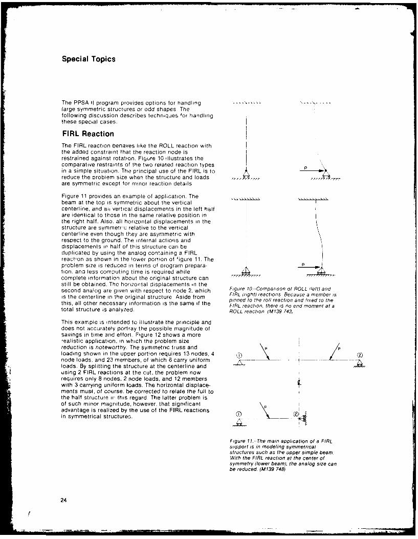
FIRL ReactionThe FIRL reaction behaves like the ROLL reaction withthe added constraint that the reaction node isrestrained against rotation. Figure 10 illustrates thecomparative restraints of the two related reaction types Pin a simple situation. The principal use of the FIRL is toreduce the problem size when the structure and loadsare symmetric except for minor reaction details.
Figure 11 provides an example of application. Thebeam at the top is symmetric about the verticalcenterline, and ah vertical displacements in the left halfare identical to those in the same relative position inthe right half. Also, all horizontal displacements in thestructure are symmetric relative to the verticalcenterline even though they are asymmetric withrespect to the ground. The internal actions anddisplacements in half of this structure can beduplicated by using the analog containing a FIRLreaction as shown in the lower portion of figure 11. Theproblem size is reduced in terms of orogram prepara- A
tion. and less computing time is required whilecomplete information about the original structure canstill be obtained. The horizontal displacements in thesecond analog are given with respect to node 2, which Figure 10.-Comparison of ROLL (left) andis the centerline in the original structure Aside from FIRL (right) reactions. Because a member is
pinned to the roll reaction and fixed to thethis, all other necessary information is the same if the FIRL reaction, there is no end moment at atotal structure is analyzed. ROLL reaction. (M139 743)
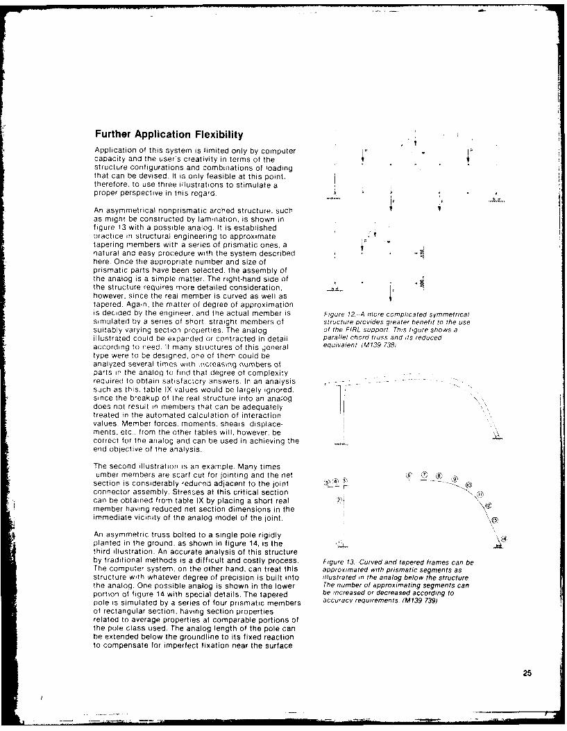
This example is intended to illustrate the principle anddoes not accurately portray the possible magnitude ofsavings in time and effort. Figure 12 shows a morerealistic application, in which the problem sizereduction is noteworthy. The symmetric truss and Pploading shown in the upper portion requires 13 nodes, 4node loads, and 23 members, of which 6 carry uniform t- - iloads. By splitting the structure at the centerline andusing 2 FIRL reactions at the cut, the problem nowrequires only 8 nodes, 2 node loads, and 12 memberswith 3 carrying uniform loads. The horizontal displace-ments must, of course, be corrected to relate the full tothe half structure in this regard. The latter problem isof such minor magnitude, however, that significant \advantage is realized by the use of the FIRL reactionsin symmetrical structures.
Figure 11--The main application of a FIRLsupport is in modeling symmetricalstructures such as the upper simple beam.With the FIRL reaction at the center ofsymmetry (lower beam), the analog size canbe reduced. (M139 748)
24
(
Further Application FlexibilityApplication of this system is limited only by computercapacity and the user's creativity in terms of thestructure configurations and combinations of loadingthat can be devised. It is only feasible at this point,therefore, to use three illustrations to stimulate aproper perspective in this regard.
An asymmetrical nonprismatic arched structure, suchas might be constructed by lamination, is shown infigure 13 with a possible analog. It is establishedpractice in structural engineering to approximatetapering members with a series of prismatic ones, anatural and easy procedure with the system described -here. Once the appropriate number and size ofprismatic parts have been selected, the assembly ofthe analog is a simple matter. The right-hand side ofthe structure requires more detailed consideration,however, since the real member is curved as well astapered. Again, the matter of degree of approximationis decided by the engineer, and the actual member is Figure 12.-A more compicated symmetricalsimulated by a series of short. straight members of structure provides greater benefit to the usesuitably varying section properties. The analog of the FIRL support. This figure shows aillustrated could be expanded or contracted in detail parallel chord tiuss and its reducedaccording to need. If many structures of this general equivalent (M139 738,type were to be designed, one of them could beanalyzed several times with increasing numbers ofparts in the analog to find that degree of complexityrequired to obtain satistactory answers. In an analysissuch as this, table IX values would be largely ignored.since the breakup of the real structure into an analogdoes not result in members that can be adequatelytreated in the automated calculation of interactionvalues. Member forces, moments, shears displace-ments. etc. from the other tables will, however, be .correct for the analog and can be used in achieving theend objective of the analysis.
The second illustration is an example. Many timeslumber members are scarf cut for jointing and the netsection is considerably reduced adjacent to the joint 0)connector assembly. Stresses at this critical sectioncan be obtained from table IX by placing a short realmember having reduced net section dimensions in theimmediate vicinity ot the analog model of the joint.p
An asymmetric truss bolted to a single pole rigidlyplanted in the ground. as shown in figure 14, is thethird illustration. An accurate analysis of this structureby traditional methods is a difficult and costly process. Figure 13- Curved and tapered frames can beThe computer system, on the other hand, can treat this approximated with prismatic segments asstructure with whatever degree of precision is built into illustrated in the analog below the structure.the analog. One possible analog is shown in the lower The number of approximating segments canportion of figure 14 with special details. The tapered be increased or decreased according topole is simulated by a series of four prismatic members acucyrqrent.(3939of rectangular se,;tion. having section propertiesrelated to average properties at comparable portions ofthe pole class used. The analog length of the pole canbe extended below the groundline to its fixed reactionto compensate for imperfect fixation near the surface
25
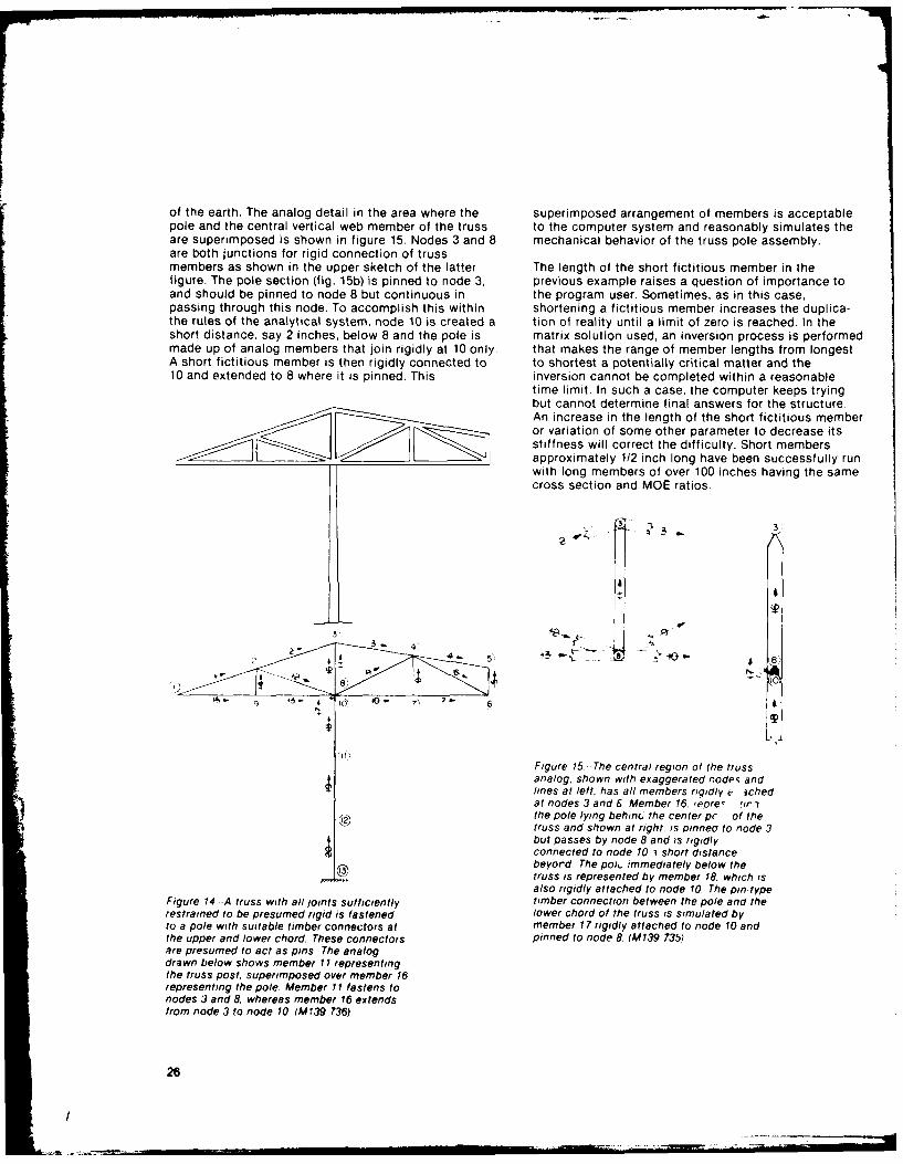
of the earth. The analog detail in the area where the superimposed arrangement of members is acceptablepole and the central vertical web member of the truss to the computer system and reasonably simulates theare superimposed is shown in figure 15. Nodes 3 and 8 mechanical behavior of the truss pole assembly.are both junctions for rigid connection of trussmembers as shown in the upper sketch of the latter The length of the short fictitious member in thefigure. The pole section (fig. 15b) is pinned to node 3, previous example raises a question of importance toand should be pinned to node 8 but continuous in the program user. Sometimes, as in this case,passing through this node. To accomplish this within shortening a fictitious member increases the duplica-the rules of the analytical system, node 10 is created a tion of reality until a limit of zero is reached. In theshort distance, say 2 inches, below 8 and the pole is matrix solution used, an inversion process is performedmade up of analog members that join rigidly at 10 only. that makes the range of member lengths from longestA short fictitious member is then rigidly connected to to shortest a potentially critical matter and the10 and extended to 8 where it is pinned. This inversion cannot be completed within a reasonable
time limit. In such a case, the computer keeps tryingbut cannot determine final answers for the structure.An increase in the length of the short fictitious memberor variation of some other parameter to decrease itsstiffness will correct the difficulty. Short members
___________________ approximately 112 inch long have been successfully runwith long members of over 100 inches having the samecross section and MOE ratios.
3.
44
101
Figure 15. -The central region of the trussanalog, shown with exaggerated nodes andlines at left, has all members rigidly e' ichedat nodes 3 and 6 Member 16, repre, !irthe pole lying behinc the center pr of thetruss and shown at right, is pinneo to node 3but passes by node 8 and is rigidlyconnected to node 10 1short distance
C13) beyord. The poh. immediately below thetruss is represented by member 18. which isalso rigidly attached to node 10. The pin-type
Figure 14 --A truss with all joints sufficiently timber connection between the pole and therestrained to be presumed rigid is fastened lower chord of the truss is simulated byto a pole with suitable timber connectors at member 17 rigidly attached to node 10 andthe upper and lower chord. These connectors pinned to node 8. (M139 735)are presumed to act as pins The analogdrawn below shows member 11 representingthe truss post, superimposed over member 16representing the pole Member ItI fastens tonodes 3 and 8. whereas member 16 extendsfrom node 3 to node 10. 1I39 736)
26
Acknowledgments Literature Cited
The PPSA II program is the result of contributions by National Forest Products Association. National designmany people beginning with Gregory F. Reardon of specification for wood construction. Washington, DC:CSIRO, Melbourne, Australia. Initial formulation and National Forest Products Association; 1982 edition.programming began during his residence at PurdueUniversity, Lafayette, Ind., in 1966 as a visiting Orosz, Ivan. Simplified method for calculating shearscientist. Since that time many others have contributed deflection of beams. Res. Note FPL-0210. Madison, WI:to system refinement. At Purdue Quentin B. Comus, U.S. Department of Agriculture, Forest Service, ForestForrest E. Goodrick, Larry A. Beineke, Philip J. Products Laboratory; 1970.Przestrzelski, Michael H. Triche, and Frank E. Woesteare among those who have made significant contri- Przemienlecki, J. S. Theory of matrix structuralbutions. Roy Adams, while a graduate student at analysis. New York: McGraw-Hill; 1968.Washington State University, performed a majorreorganization of the program which greatly increased Suddarth, S. K. A computerized wood engineeringits speed of operation and made its functional under- system: Purdue plane structures analyzer. Res. Pap.standing easier through an improved reorganization of FPL 168. Madison, WI: U.S. Department of Agriculture,subroutines. Forest Service, Forest Products Laboratory; 1972.
This reorganized program includes condensed versions Suddarth, S. K.; Percival, D. H.. Increasing theof subroutines developed at the Argonne National application efficiency of performance tests withLaboratory, Chicago, Ill., to calculate eigenvalues and analytic procedures. Performance concept in buildings.has been the foundation for further development during Spec. Publ. 361, vol. 1. Washington, DC: U.S.the past several years. The authors are also grateful for Department of Commerce, National Bureau ofthe cooperation of member companies of the Truss Standards; 1972.Plate Institute. Engineers and systems analysts inthese companies have made many trial runs of develop- Zlenkiewicz, 0. C. The finite element method inmental versions of PPSA II. Their findings and structural and continuum mechanics. New York:comments have led to many refinements and improve- McGraw-Hill; 1967.ments in the program.
27
Appendix AInput Data
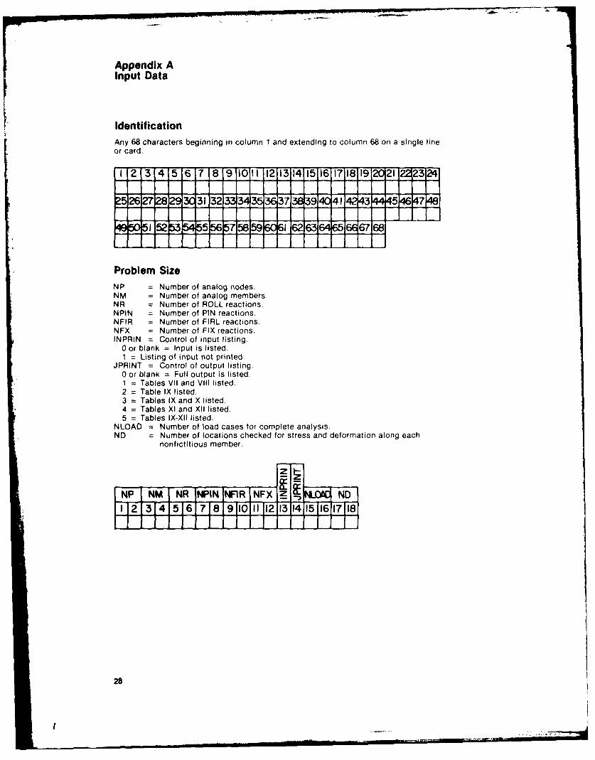
IdentificationAny 68 characters beginning in column 1 and extending to column 68 on a single lineor card.
I 213 415 6 7 8 9 1011 12131415161718 19 2 21 231:
25ziz 25 ZT 9ea31 32 3334r35 3 ,37 8 40 11 43 4,5* 7
501525 5 575 9 6345166 68
Problem SizeNP = Number of analog nodes.NM = Number of analog members.NR = Number of ROLL reactions.NPIN = Number of PIN reactions.NFIR = Number of FIRL reactions,NFX = Number of FIX reactions.INPRIN = Control of input listing.
0 or blank = Input is listed.1 = Listing of input not printed.
JPRINT = Control of output listing.0 or blank = Full output is listed.1 = Tables VII and VIII listed.2 = Table IX listed.3 = Tables IX and X listed.4 = Tables XI and XII listed.5 = Tables IX-XII listed.
NLOAD = Number of load cases for complete analysis.ND = Number of locations checked for stress and deformation along each
nonfictitious member.
INP INM NR ININ NFIR INFX Z ND1.28 L1 5 61718 o '13]14 t6178
28
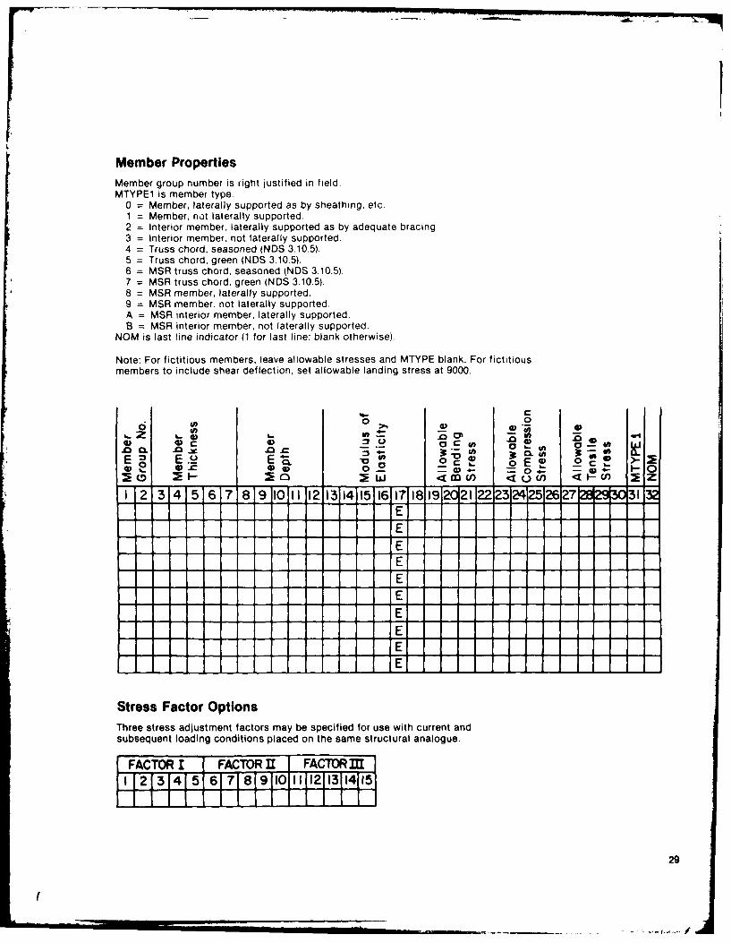
Member PropertiesMember group number is right justified in field.MTYPE1 is member type.
0 = Member, laterally supported as by sheathing, etc.1 = Member, not laterally supported.2 = Interior member, laterally supported as by adequate bracing.3 = Interior member, not laterally supported.4 = Truss chord, seasoned (NDS 3.10.5).5 = Truss chord, green (NDS 3.10.5).6 = MSR truss chord, seasoned (NDS 3.10.5).7 = MSR truss chord, green (NDS 3.10.5).8 = MSR member, laterally supported.9 = MSR member, not laterally supported.A = MSR interior member, laterally supported.B = MSR interior member, not laterally supported.
NOM is last line indicator (1 for last line; blank otherwise).
Note: For fictitious members, leave allowable stresses and MTYPE blank. For fictitiousmembers to include shear deflection, set allowable landing stress at 9000.
%4-00 0
4-4.
0 0 0 .-
1 2 3 4 5 6 7 8 9 10 12 1314 15116 17 1819 _21 22-2324252627'2901EEEEEEEE]
EE
Stress Factor OptionsThree stress adjustment factors may be specified for use with current andsubsequent loading conditions placed on the same structural analogue.
FACTOR I FACTOR 311 FACTOR MS1213 41 5 61 7 81911011 1112113114115
29
,( .. . ... ... .. .. . . '
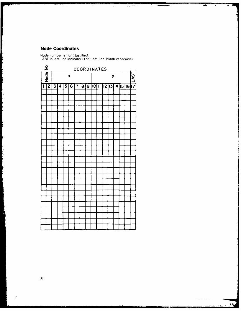
Node CoordinatesNode number is right justified.LAST is last line indicator (1 for last line; blank otherwise).
COORDINATES0V x y C,
1 2 314 5 6 71819 1011 1213141511617
30
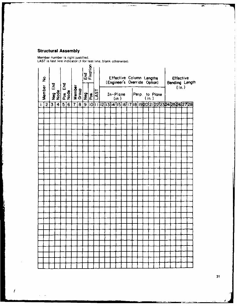
Structural AssemblyMember number is right justified.LAST is last line indicator (1 for last line blank otherwise).
w.Effective Column Lengths Effective(Engineer's Override Option) Bending Length
E o 00 eo a In-Plane Perp to Plane.zZ a. z 6i (in.) (in.)
I 234 5 6 789 iO ll 1213 14IlIr117I819 20212223P 252 2128
31
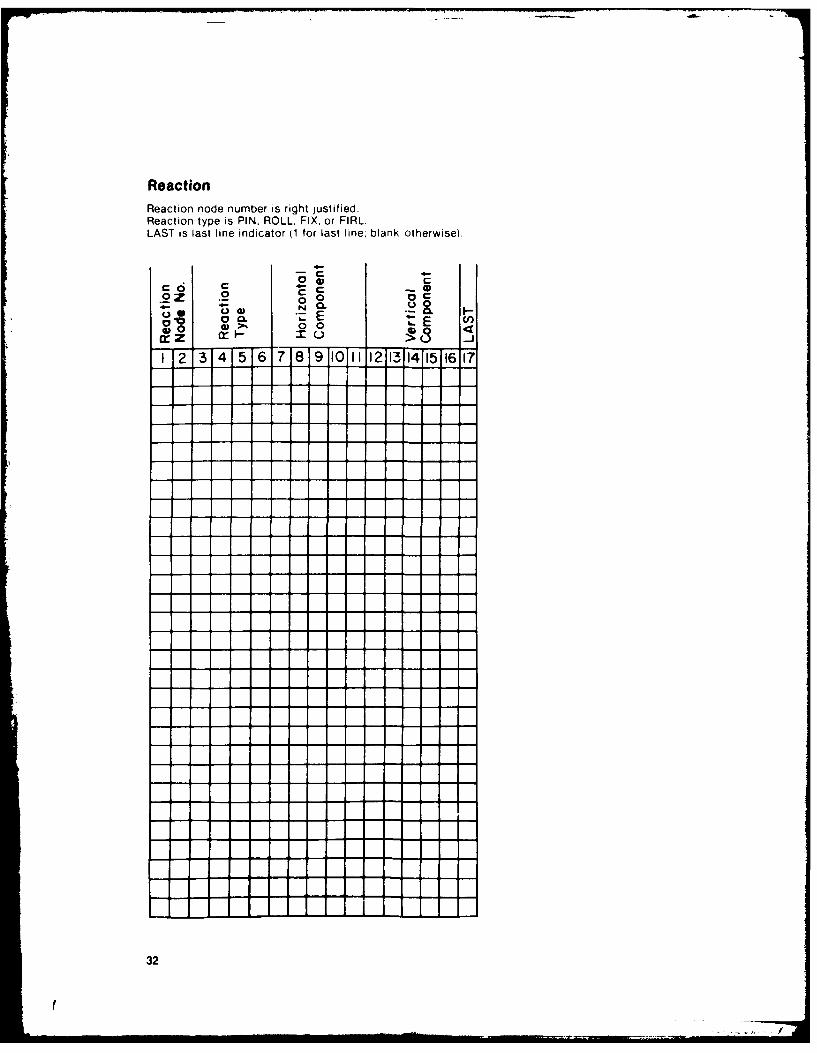
ReactionReaction node number is right justified.Reaction type is PIN. ROLL. FIX, or FIRL.LAST is last line indicator (1 for last line: blank otherwise).
C ~4- 4
.2 .2.2~~ .0zE - (
IV000 ECrz ir 10M (
1T234156789011 12131415 6 17
32
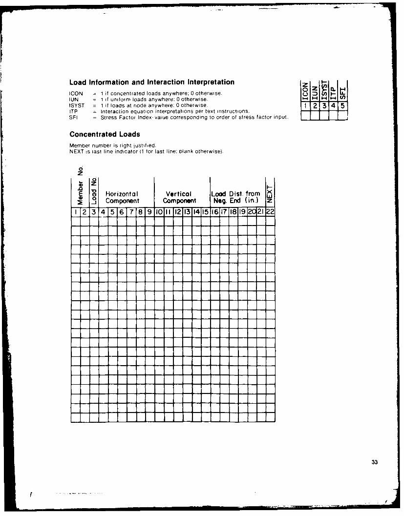
Load Information and Interaction Interpretation zICON = 1 if concentrated loads anywhere; 0 otherwise.UN = 1 if uniform loads anywhere: 0 otherwise.ISYST = 1 if loads at node anywhere: 0 otherwise. II 12131415ITP = Interaclion equation interpretations per text instructions.SF1 = Stress Factor Index--value corresponding to order of stress factor input. jTIj -J,Concentrated LoadsMember number is right justified.NEXT is last line indicator (1 for last line; blank otherwise).
0zZ
E a Horizontal Vertical Load Dist. from x0 Component Component Neg. End (in.) z
1 23 4 5 6 7 8 9 I0 I 12 1314115 1617 1811912 21.22
33
l .. I ... -I'r% : " ". . '
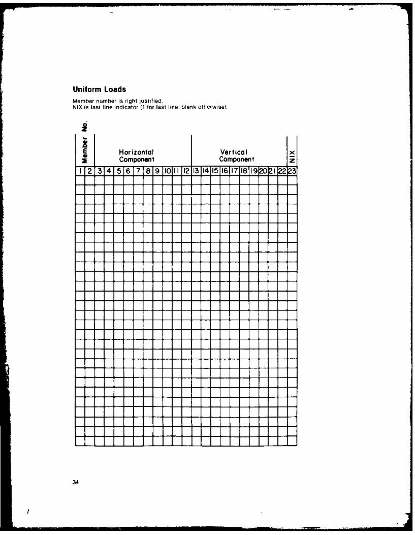
Uniform LoadsMember number is right justified.NIX is last line indicator (1 for last line; blank otherwise).
E Horizontal Vertical _
Component Component
I 2 3 4 5 6 7 8 9 011 121314 15 1611718 1920 21 222
!3
i
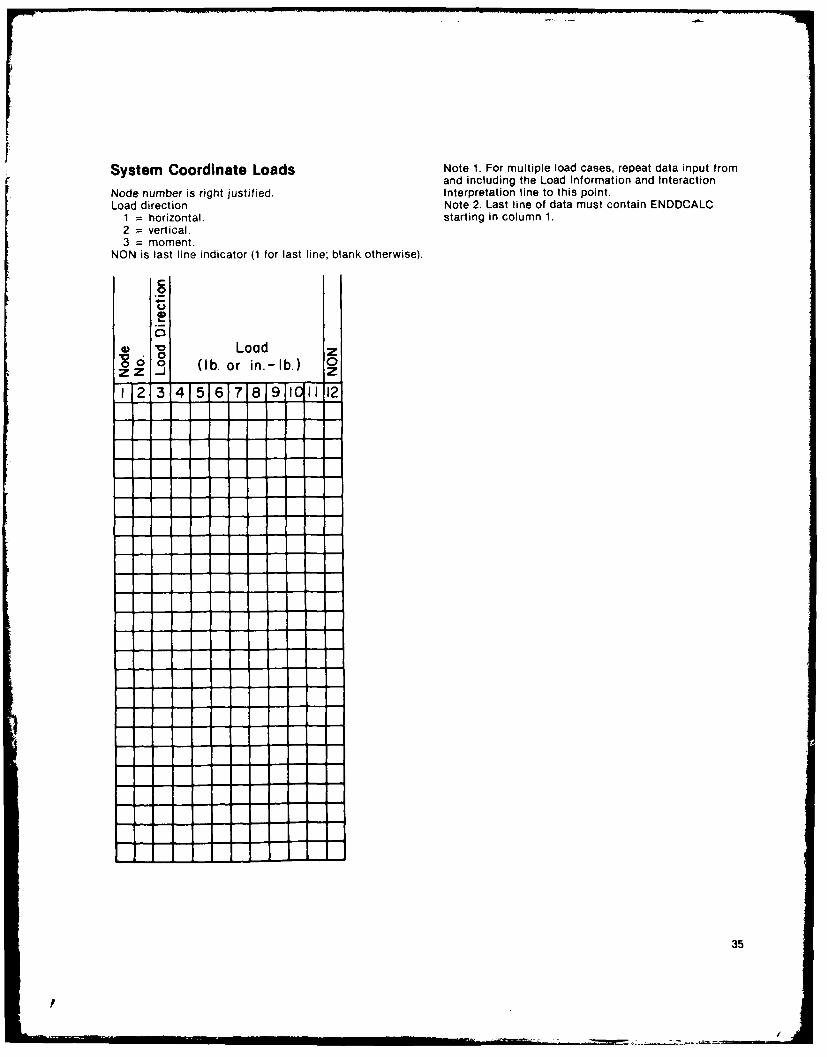
System Coordinate Loads Note 1. For multiple load cases, repeat data input fromand including the Load Information and Interaction
Node number is right justified. Interpretation line to this point.Load direction Note 2. Last line of data must contain ENDDCALC
1 = horizontal, starting in column 1.2 = vertical.3 = moment.
NON is last line indicator (1 for last line; blank otherwise).
0 Load Zo (b. or in.-lb.) 0
zz -J Z1 -2 314 5 6 718 9 101112
35
p
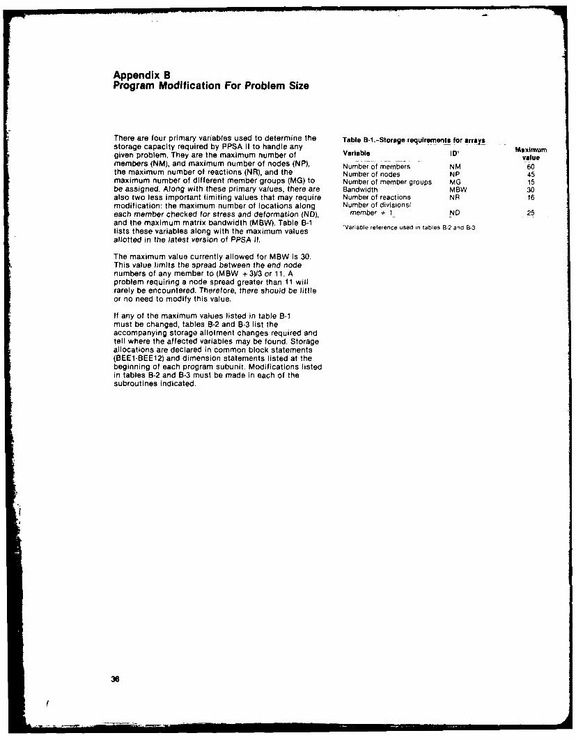
Appendix BProgram Modification For Problem Size
There are four primary variables used to determine the Table B-1...Storage requirements for arraysstorage capacity required by PPSA II to handle any Maximumgiven problem. They are the maximum number of Variable ID' valuemembers (NM), and maximum number of nodes (NP), Number of members NM 60the maximum number of reactions (NR), and the Number of nodes NP 45maximum number of different member groups (MG) to Number of member groups MG 15be assigned. Along with these primary values, there are Bandwidth MBW 30also two less important limiting values that may require Number of reactions NR 16modification: the maximum number of locations along Number of divisions/each member checked for stress and deformation (ND), member + 1 ND 25and the maximum matrix bandwidth (MBW). Table B-1 Variable reference used in tables B-2 and B-3.lists these variables along with the maximum valuesallotted in the latest version of PPSA I1.
The maximum value currently allowed for MBW is 30.This value limits the spread between the end nodenumbers of any member to (MBW + 3)/3 or 11. Aproblem requiring a node spread greater than 11 willrarely be encountered. Therefore, there should be littleor no need to modify this value.
If any of the maximum values listed in table B-1must be changed, tables B-2 and B-3 list theaccompanying storage allotment changes required andtell where the affected variables may be found. Storageallocations are declared in common block statements(BEE1-BEE12) and dimension statements listed at thebeginning of each program subunit. Modifications listedin tables B-2 and B-3 must be made in each of thesubroutines indicated.
3e
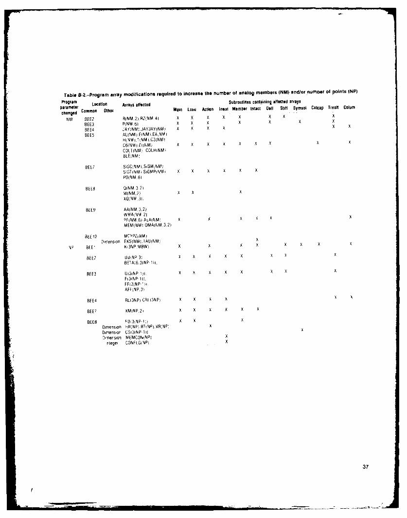
Table 8-2..Program array modifications required to increase the number of analog members (NM) and/or numoer of points (NP)
Program Location Arrays affected Subroutines containinj affected arraysparameterchanqed Common Other Main Loam Action Inout Member Intact Deti Stift Symsoi Caicap Trnsit Coium
NIA BEE? R(NM 2).RZfNM,4) X X X X X X x x
BEE3 P(NM.6) X x X x X x x
BEE4 JAY(NM).JAYJAY(NM) x X x x x x
BEES AL(NM).E(NM).EA(NM)H)NM ,TiNM .C3)NM)C6(NM).E)(NM) x x X X X X X x x
COLT(NML, COLHtNM)BLE)NM)
BEE? SIGC)NMi.SIGMiNM)S1GT(NM).SIGMP(NM) x X X x X XPO(NM. 6)
BEES O(NM,3,2WINMI,2), X x XXO(NM .3i.
BEE9 AA)NM.3 2)WMA)NM.2)PF(NM.6).ALA(NM) x x x X X x
MEMINM) OMANM,3,2)
BEE10 MITYPE(NM)Dimension EKS)NM).TAU(NM) x
NP BEE1 K13NP.MBW) x x X X x X X
BEE2 JU(NP 3 X X )( X X X X x
BETA)6.3(NP- 1)).
BEE3 U(31NP-l. 1)) X x x X x x X xF(3(NP- 1)FF(3)NP 1)),AFF(NP,3)
BEE4 RL)3NP) CRL)3NP) x x x x
BEE? XM)NP.21 x x x x x x
BEES FOD3NP-1) x x xDimension HR)NPi.RT)NP).VR(NP) xDimension CS3)NP-1)) x
Dimension MEMCON(NP) x
Integer CONFLG(NP) -
37
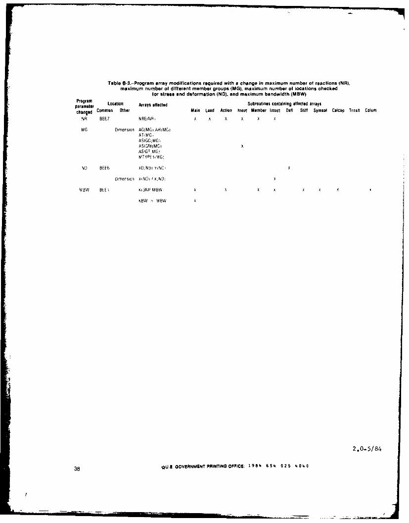
Table 8-3..Program array modifications required with a change in maximum number of reactions tNR),maximum number of different member groups (MG), maximum number of locations checked
for stress and deformation (ND), and maximum bandwidth (MBW)Program Location Array% affected Subroutines containing affected arrays
parameter
changed Common Other Main Load Action Inouf Member Intact Dofti Stiff Symsot Calcap Trnstt Colum
MG Dimension AG(MG.,AHtMGiATiMGiASIGC(MG iASIGM MG) XAS IG 1MGDM TYPE 1 MG
NO BEE6 XDiNDi Y1ND, X
Dimension XiN~p FXNLIp
MBW BEE 1K13NP MBWi X X X X X X X
KBW MBW X
2.0-5/84
38 *u.S. GOVERNMENT PRINTING OFFICE; 1 9 84 6 54 025 4.04a.0