Embed Size (px)
Citation preview
1
PureWatts Elite Power Inverter
Instruction Manual
1000 / 2000 WATTS
www.sinergex.com
2
CONTENTS
Introduction _____________________________________ 3 Important Safety Information _________________________ 3 Features & Applications _____________________________ 4 Electrical Performance _____________________________ 5 Mechanical Drawings _____________________________ 7 DC Wiring Connections _____________________________ 9 Battery to Inverter Cable Connection _________________ 10 Installation _____________________________________ 11 Troubleshooting _________________________________ 12
Maintenance & Warranty _____________________________ 13
3
INTRODUCTION WARNING! Before you install and use your Nitro Battery Charger, be sure to read and save these safety instructions. INTRODUCTION Thanks for choosing Sinergex to help you with your power needs. The Sinergex PureWatts Elite inverters are members of the family of advanced mobile power products manufactured by Sinergex Technologies. PureWatts inverters will deliver you efficient AC power allowing you to run your equipment anywhere, anytime. Please carefully read and follow the following safety and operating instructions.
IMPORTANT SAFETY INFORMATION
1. General Safety Precautions 1-1. Do not expose the inverter to liquid, mist, snow, or dust. To reduce the risk of fire, do
not cover or obstruct the air flow vents. Do not install the inverter in a zero-clearance compartment as overheating may occur.
1-2. To avoid the risk of fire and electric shock, make sure that existing wiring is in good
electrical condition and not undersized. Do not operate the inverter with damaged or substandard wiring.
1-3. There are some components of the inverter that can cause arcs and sparks. To prevent fire or explosion, install and operate the inverter in an area that is free from the batteries, flammable materials, or anything which should be ignition-protected.
2. Precautions When Working with Batteries 2-1. If battery acid contacts your skin or clothing, wash the contacted area with soap and
water immediately. If battery acid contacts your eyes, you wash eyes with cold running water for at least 20 minutes and get medical attention immediately.
2-2. Never smoke, make a spark or flame in the vicinity of the battery or the engine. 2-3. Avoid dropping any metal object on the battery. The resulting sparks or short-circuit
from the battery or other electrical parts may cause an explosion. 2-4. Remove personal metal items such as rings, bracelets, necklaces, and watches when
operating with lead-acid batteries. Failing to do so may cause a short circuit and very high temperatures, which can melt metal items and cause burning.
WARNING! Before using the Inverter, read and save the safety instructions.
1
4
FEATURES & APPLICATIONS
Regulated Modified Sine Wave Output
Output frequency:50 / 60Hz
Input & Output Fully Isolated
High Efficiency >80%
LED Power and Protection Display
Load Controlled Cooling Fan
Protection: Input Low Voltage Short Circuit Reverse Polarity (Fuse) Input over voltage Over Temperature Overload Applications 1. Power Tools – circular saws, drills, grinders, sanders, weed and hedge trimmers, etc. 2. Office Equipment – computers, printers, monitors, facsimile machines, and scanners, etc. 3. Household Appliances – small vacuum cleaners, fans, incandescent lights, shavers, sewing
machines, etc. 4. Kitchen Appliances – coffee makers, blenders, ice makers, food processors, etc. 6. Home Entertainment & Electronics – television, VCRs, video games, stereos, musical
instruments and satellite equipment, etc. 5. Other – control equipment, cars, boots, solar energy driven, weekend homes, camping
activities.etc.
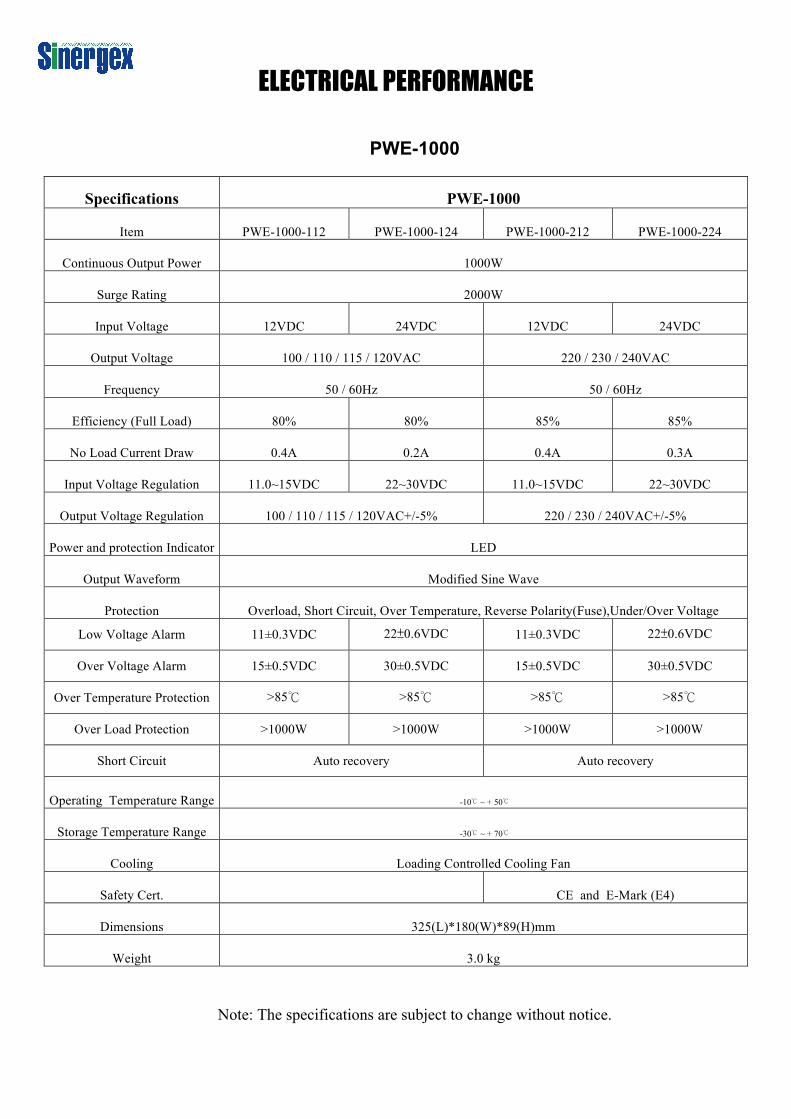
ELECTRICAL PERFORMANCE
PWE-1000
Specifications PWE-1000
Item PWE-1000-112 PWE-1000-124 PWE-1000-212 PWE-1000-224
Continuous Output Power 1000W
Surge Rating 2000W
Input Voltage 12VDC 24VDC 12VDC 24VDC
Output Voltage 100 / 110 / 115 / 120VAC 220 / 230 / 240VAC
Frequency 50 / 60Hz 50 / 60Hz
Efficiency (Full Load) 80% 80% 85% 85%
No Load Current Draw 0.4A 0.2A 0.4A 0.3A
Input Voltage Regulation 11.0~15VDC 22~30VDC 11.0~15VDC 22~30VDC
Output Voltage Regulation 100 / 110 / 115 / 120VAC+/-5% 220 / 230 / 240VAC+/-5%
Power and protection Indicator LED
Output Waveform Modified Sine Wave
Protection Overload, Short Circuit, Over Temperature, Reverse Polarity(Fuse),Under/Over Voltage
Low Voltage Alarm 11±0.3VDC 22±0.6VDC 11±0.3VDC 22±0.6VDC
Over Voltage Alarm 15±0.5VDC 30±0.5VDC 15±0.5VDC 30±0.5VDC
Over Temperature Protection >85℃ >85℃ >85℃ >85℃
Over Load Protection >1000W >1000W >1000W >1000W
Short Circuit Auto recovery Auto recovery
Operating Temperature Range -10℃ ~ + 50℃
Storage Temperature Range -30℃ ~ + 70℃
Cooling Loading Controlled Cooling Fan
Safety Cert. CE and E-Mark (E4)
Dimensions 325(L)*180(W)*89(H)mm
Weight 3.0 kg
Note: The specifications are subject to change without notice.
6
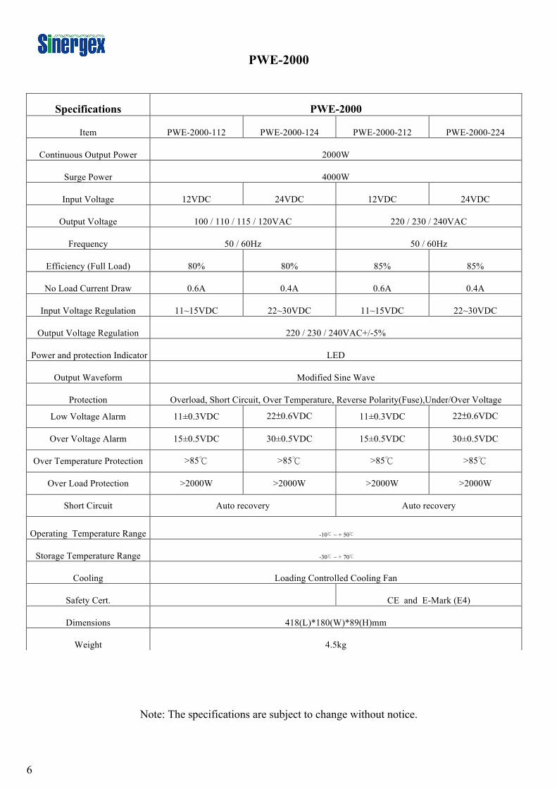
PWE-2000
Note: The specifications are subject to change without notice.
Specifications PWE-2000
Item PWE-2000-112 PWE-2000-124 PWE-2000-212 PWE-2000-224
Continuous Output Power 2000W
Surge Power 4000W
Input Voltage 12VDC 24VDC 12VDC 24VDC
Output Voltage 100 / 110 / 115 / 120VAC 220 / 230 / 240VAC
Frequency 50 / 60Hz 50 / 60Hz
Efficiency (Full Load) 80% 80% 85% 85%
No Load Current Draw 0.6A 0.4A 0.6A 0.4A
Input Voltage Regulation 11~15VDC 22~30VDC 11~15VDC 22~30VDC
Output Voltage Regulation 220 / 230 / 240VAC+/-5%
Power and protection Indicator LED
Output Waveform Modified Sine Wave
Protection Overload, Short Circuit, Over Temperature, Reverse Polarity(Fuse),Under/Over Voltage
Low Voltage Alarm 11±0.3VDC 22±0.6VDC 11±0.3VDC 22±0.6VDC
Over Voltage Alarm 15±0.5VDC 30±0.5VDC 15±0.5VDC 30±0.5VDC
Over Temperature Protection >85℃ >85℃ >85℃ >85℃
Over Load Protection >2000W >2000W >2000W >2000W
Short Circuit Auto recovery Auto recovery
Operating Temperature Range -10℃ ~ + 50℃
Storage Temperature Range -30℃ ~ + 70℃
Cooling Loading Controlled Cooling Fan
Safety Cert. CE and E-Mark (E4)
Dimensions 418(L)*180(W)*89(H)mm
Weight 4.5kg
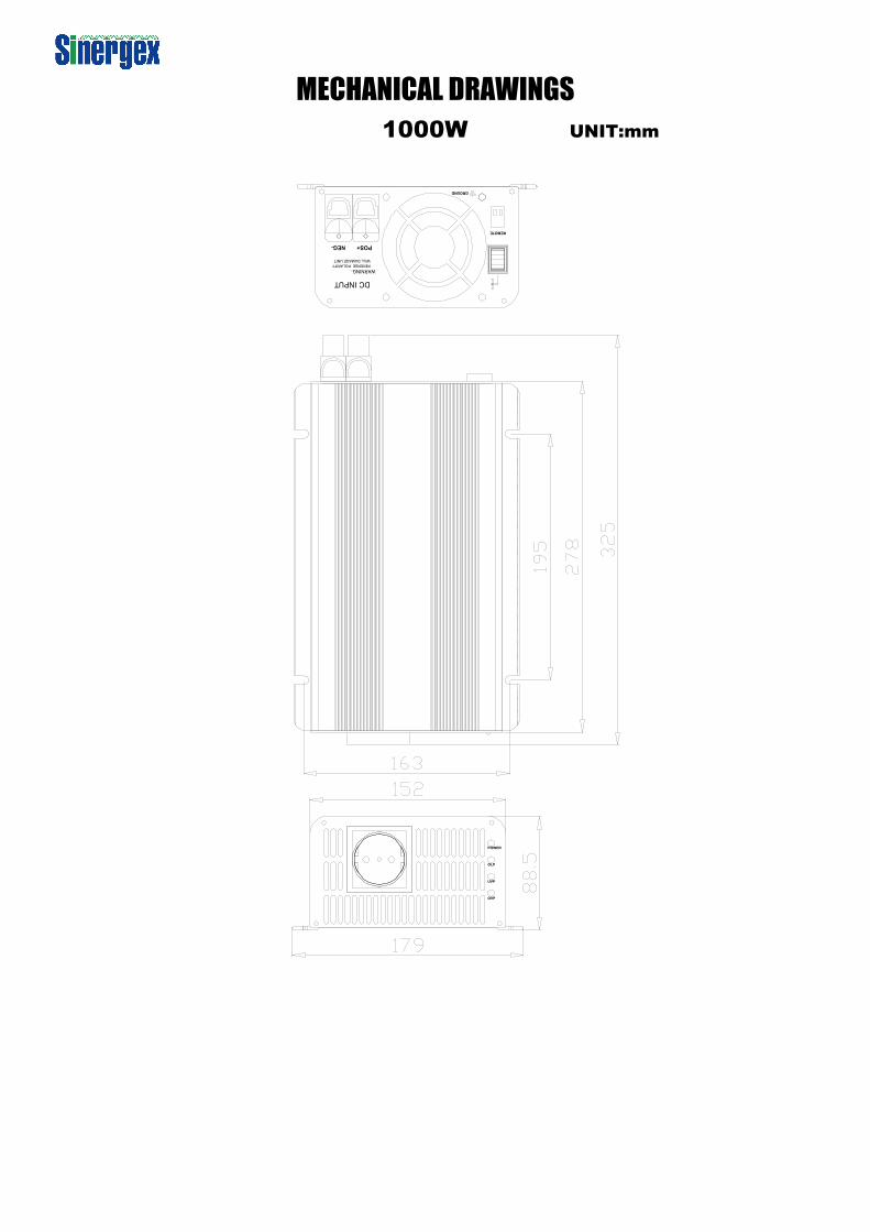
MECHANICAL DRAWINGS 1000W UNIT:mm
8
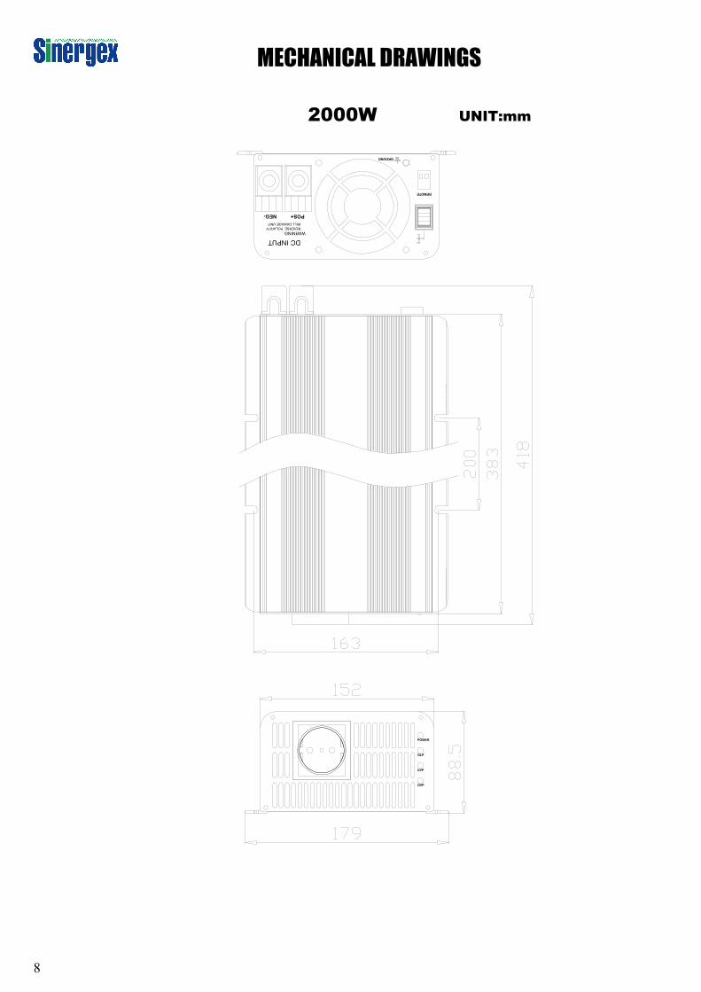
MECHANICAL DRAWINGS
2000W UNIT:mm
9
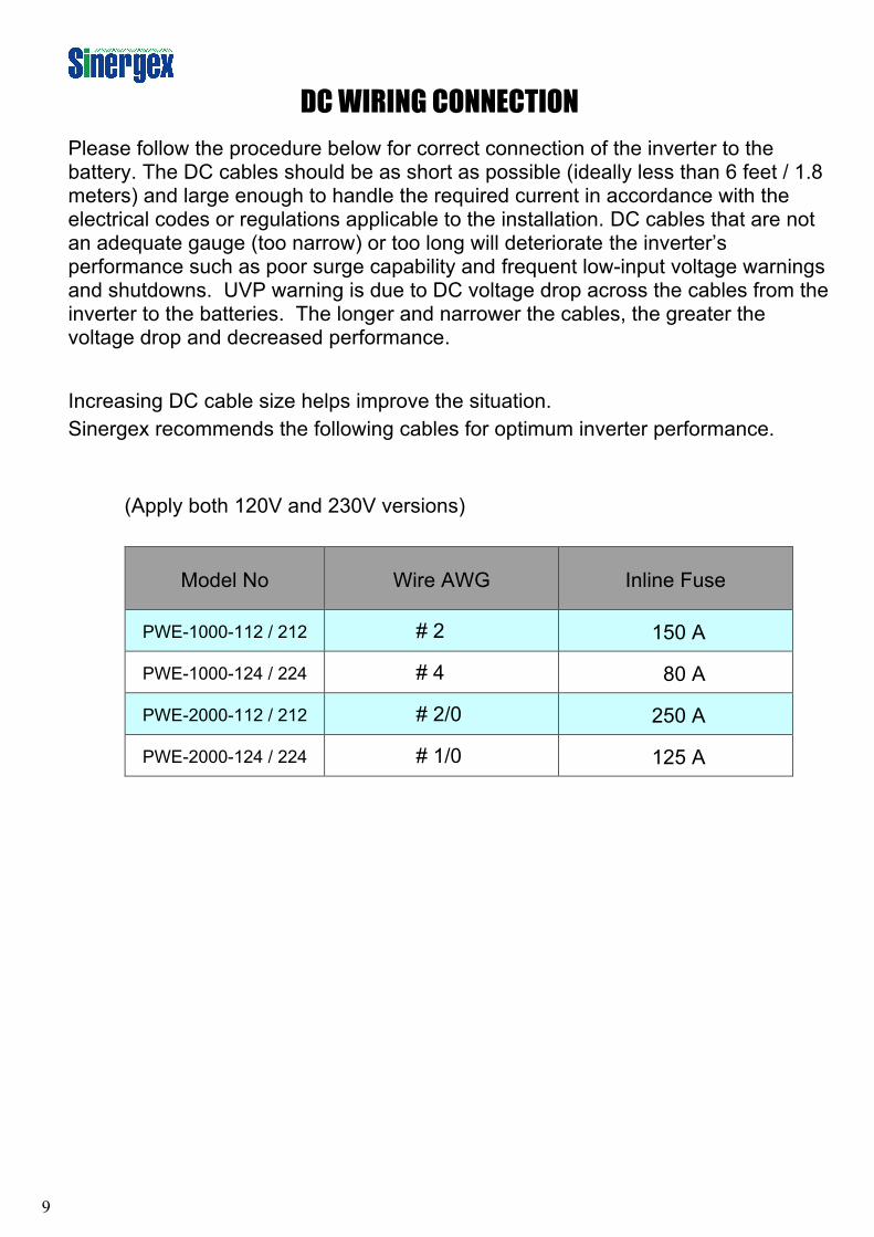
DC WIRING CONNECTION Please follow the procedure below for correct connection of the inverter to the battery. The DC cables should be as short as possible (ideally less than 6 feet / 1.8 meters) and large enough to handle the required current in accordance with the electrical codes or regulations applicable to the installation. DC cables that are not an adequate gauge (too narrow) or too long will deteriorate the inverter’s performance such as poor surge capability and frequent low-input voltage warnings and shutdowns. UVP warning is due to DC voltage drop across the cables from the inverter to the batteries. The longer and narrower the cables, the greater the voltage drop and decreased performance.
Increasing DC cable size helps improve the situation. Sinergex recommends the following cables for optimum inverter performance.
(Apply both 120V and 230V versions)
Model No Wire AWG Inline Fuse
PWE-1000-112 / 212 # 2 150 A
PWE-1000-124 / 224 # 4 80 A
PWE-2000-112 / 212 # 2/0 250 A
PWE-2000-124 / 224 # 1/0 125 A
10
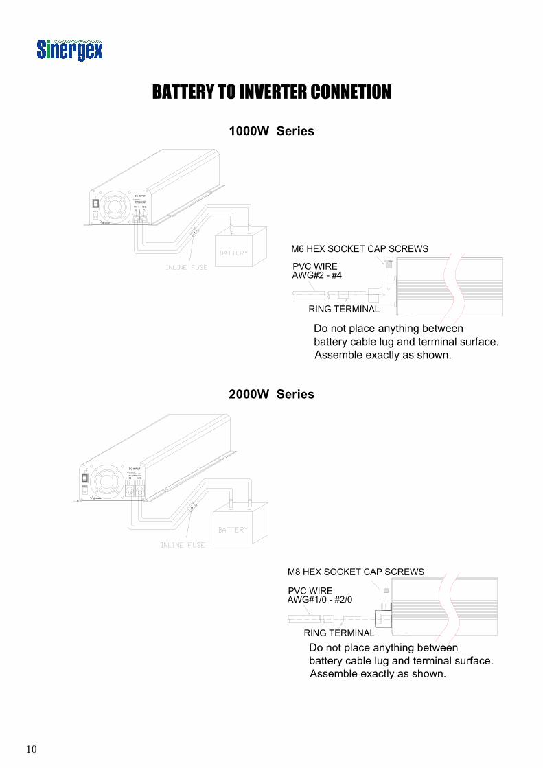
BATTERY TO INVERTER CONNETION
1000W Series
2000W Series
11
INSTALLATION
1. The Sinergex PureWatts Elite inverters are some of the most advanced mobile AC power
systems available. To ensure the power inverter functions correctly, please read and follow these instructions before and during installation.
2. Before installing the inverter, ensure the inverter’s power switch is “OFF”. Connect the DC
cables to the 12V / 24V battery or the other DC power source. 【+】RED represents positive,【-】BLACK represents negative. Ensure you connect the positive terminal of the inverter to the positive terminal of the battery. Do the same with the negative DC cable. Reverse polarity connection will blow internal fuse and may damage the inverter permanently. Ensure all the DC connections are tight and secure (torque to 9 – 10 ft-lbs, 11.7 – 13 Nm) or overheating may occur. Chassis Ground: use # 8 AWG wire to connect the vehicle’s chassis. Operating the inverter without a proper ground connection may result in an electrical safety hazard.
3. Close to Batteries – Avoid excessive cable lengths. Do not install the inverter in the same
compartment as batteries. Use the recommended wire lengths and sizes (see page 9). Do not mount the inverter where it will be exposed to the gases produced by the battery. These gases are very corrosive and prolonged exposure may damage the inverter. Shock Hazard. Before proceeding further, carefully check that the inverter is NOT connected to any batteries, and that all wiring is disconnected from any electrical sources. Do not connect the output terminals of the inverter to an incoming AC source.
4. To operate the power inverter, turn the main switch ON. The power inverter is now ready to
deliver AC power to your loads. If there are several loads used, turn them on separately after the inverter is “ON” in order to prevent over voltage.
6. ON / OFF/ REMOTE switch:Leave the Power ON / OFF / REMOTE switch in the OFF
position during installation. Remote Port: Placing 0.75mm2 and Screw type cable between remote port and panel.
12
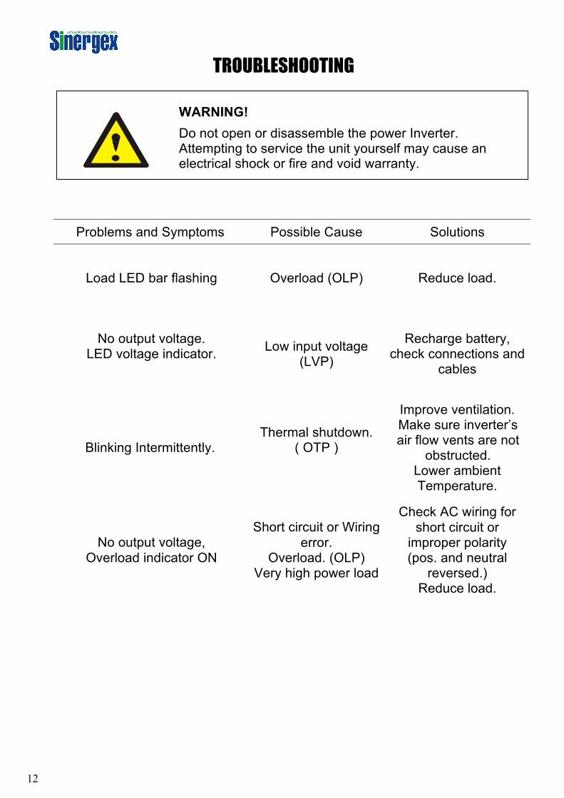
TROUBLESHOOTING
Problems and Symptoms Possible Cause Solutions
Load LED bar flashing Overload (OLP) Reduce load.
No output voltage. LED voltage indicator.
Low input voltage (LVP)
Recharge battery, check connections and
cables
Blinking Intermittently. Thermal shutdown.
( OTP )
Improve ventilation. Make sure inverter’s air flow vents are not
obstructed. Lower ambient Temperature.
No output voltage, Overload indicator ON
Short circuit or Wiring error.
Overload. (OLP) Very high power load
Check AC wiring for short circuit or
improper polarity (pos. and neutral
reversed.) Reduce load.
WARNING! Do not open or disassemble the power Inverter. Attempting to service the unit yourself may cause an electrical shock or fire and void warranty.
13
MAINTANENCE Very little maintenance is required to keep your inverter operating properly. You should clean the exterior of the unit periodically with a damp cloth to prevent accumulation of dust and dirt. Always ensure the connecting screws at the battery and inverter terminals are tight and secure.
WARRANTY
Sinergex Technologies warrants this product for a period of 2 years from the date of purchase to the original purchaser. Warranty is not transferable. Warranty covers defect against workmanship and materials only. To obtain warranty service, please return the unit to the place of purchase or authorized Sinergex dealer together with your proof of purchase. The warranty is void if the product has been damaged or not used as described in this manual. Warranty is void if a non-authorized repair has been performed. Sinergex Technologies makes no other warranty expressed or implied. Sinergex Technologies is only responsible for repair or replacement (at Sinergex Technologies’ Discretion) of the defective product and is not responsible for any consequential damage or inconvenience caused by the defect
Sinergex Technologies L.L.C.