Embed Size (px)
Citation preview
172
Pvc-U Ball valveS - Pn 10 SerieS válvulaS de bola Pvc-u - Serie Pn 10
Sizes Solvent cement D16 - D110 (DN10-DN100)Threaded ⅜” - 4”
Standards Solvent socket - MetricThreaded - BSPCompression - metric, IPS, CTS
EN ISO 1452, EN ISO 15493ISO 228-1
Working pressure @ 20ºC (73ºF)
D16 - D110 (3/8” - 4”): PN 10 (150 psi)
Materials O-rings: EPDM Ball seats: HDPE
Characteristics • “Antiblock” system that avoids ball blockage.• 100% factory tested.• Minimal pressure drop.• Low operating torque.• Resistance to many inorganic chemicals.• Excellent flow characteristics.
• Sistema “Antiblock” que evita el bloqueo de la bola.• Probadas al 100% en fábrica.• Mínima pérdida de carga.• Bajo par de apertura y cierre.• Resistencia a múltiples substancias químicas inorgánicas.• Excelentes características de conducción.
Certifications / regulations Ball valve design regulation - EN ISO 16135
PVC-U BALL VALVE PN10 SERIES
173
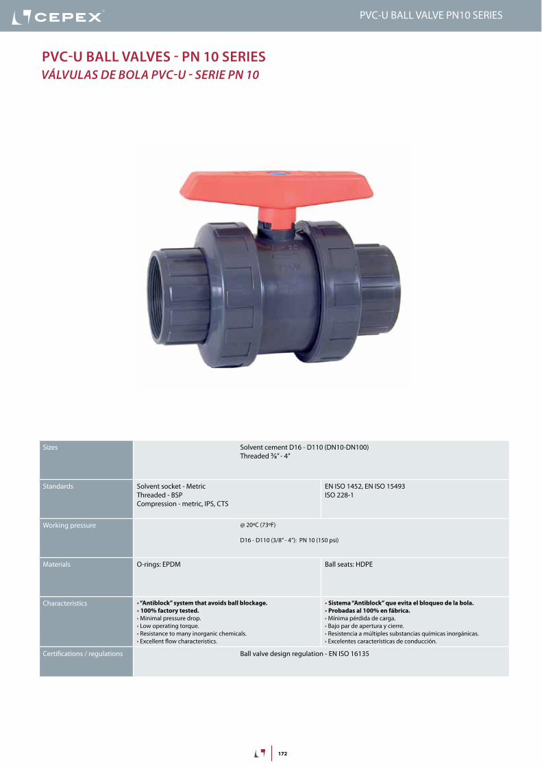
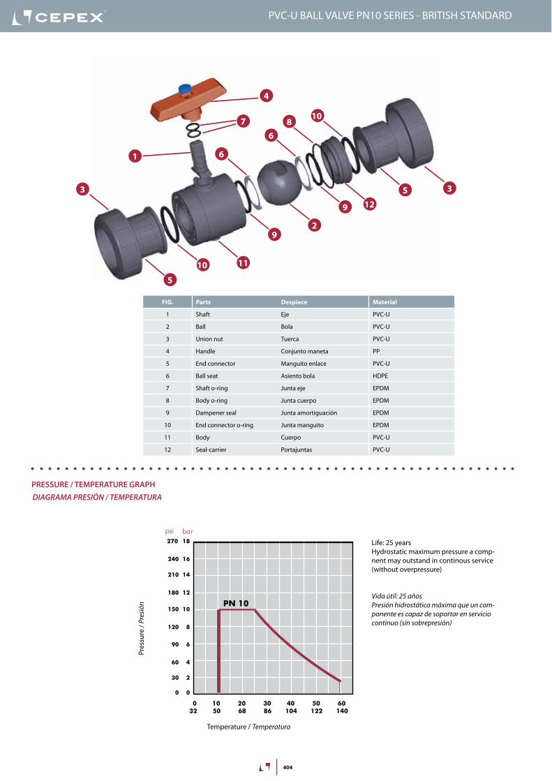
FIG. Parts Despiece Material
1 Shaft Eje PVC-U
2 Ball Bola PVC-U
3 Union nut Tuerca PVC-U
4 Handle Conjunto maneta PP
5 End connector Manguito enlace PVC-U
6 Ball seat Asiento bola HDPE
7 Shaft o-ring Junta eje EPDM
8 Body o-ring Junta cuerpo EPDM
9 Dampener seal Junta amortiguación EPDM
10 End connector o-ring Junta manguito EPDM
11 Body Cuerpo PVC-U
12 Seal-carrier Portajuntas PVC-U
1
2
3
4
9
6
7
9
5
810
3
5
6
11
12
10
DN
40
-1½
”DN
50
-2”
0,1
10 (l/min)
bar
Kv (l/min , p = 1 bar)
0,01
0,001
1
100 1.000 10.000
(GPM)26,42 264 2.642
1,50
0,15
0,01
15,0
psi
Flow / Débit / Caudal / Caudal
Pres
sure
loss
/Per
tede
char
ge/
Pérd
ida
deca
rga
/Per
dasd
eca
rga
20 years / water flow20 années / fluide de l�eau20 años / fluido de agua20 anos / caudal de água
18
16
14
12
10
8
6
4
2
0
0 10 20 30 40 50 60
Temperature / Température / Temperatura / Temperatura
Pres
sure
/Pre
ssio
n/ P
resió
n/ P
ress
ão
°C32 50 68 86 104 122 140 °F
barpsi270
240
210
180
150
120
90
60
30
0
2,64
PN 10
PreSSUre / teMPeratUre graPhdiaGraMa PreSión / TeMPeraTura
Pres
sure
/ Pr
esió
n
Temperature / Temperatura
vida útil: 25 añosPresión hidrostática máxima que un com-ponente es capaz de soportar en servicio continuo (sin sobrepresión)
PVC-U BALL VALVE PN10 SERIES
Life: 25 yearsHydrostatic maximum pressure a comp-nent may outstand in continous service (without overpressure)
174
DN
40
-1½
”DN
50
-2”
0,1
10 (l/min)
bar
Kv (l/min , p = 1 bar)
0,01
0,001
1
100 1.000 10.000
(GPM)26,42 264 2.642
1,50
0,15
0,01
15,0
psi
Flow / Débit / Caudal / Caudal
Pres
sure
loss
/Per
tede
char
ge/
Pérd
ida
deca
rga
/Per
dasd
eca
rga
20 years / water flow20 années / fluide de l�eau20 años / fluido de agua20 anos / caudal de água
18
16
14
12
10
8
6
4
2
0
0 10 20 30 40 50 60
Temperature / Température / Temperatura / Temperatura
Pres
sure
/Pre
ssio
n/ P
resió
n/ P
ress
ão
°C32 50 68 86 104 122 140 °F
barpsi270
240
210
180
150
120
90
60
30
0
2,64
PN 10
PVC-U BALL VALVE PN10 SERIES
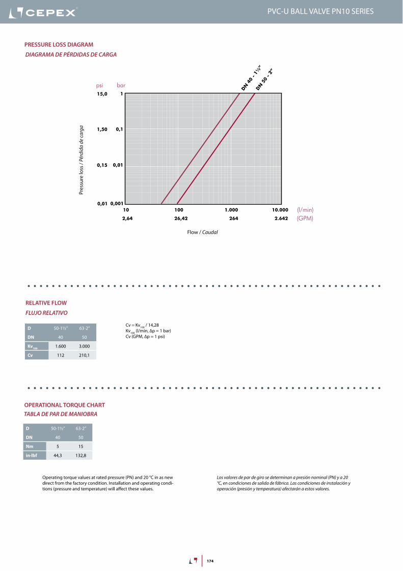
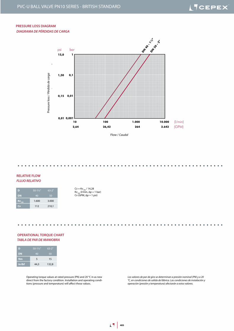
PreSSUre lOSS DiagraM
diaGraMa de PÉrdidaS de carGa
Pres
sure
loss
/ Pé
rdid
a de
carg
a
Flow / caudal
Cv = Kv100 / 14,28Kv100 (l/min, ∆p = 1 bar)Cv (GPM, ∆p = 1 psi)
D 50-1½” 63-2”
DN 40 50
Kv100 1.600 3.000
Cv 112 210,1
relative FlOW
FluJo relaTivo
OPeratiOnal tOrQUe chartTabla de Par de Maniobra
Operating torque values at rated pressure (PN) and 20 °C in as new direct from the factory condition. Installation and operating condi-tions (pressure and temperature) will affect these values.
Los valores de par de giro se determinan a presión nominal (Pn) y a 20 °c, en condiciones de salida de fábrica. Las condiciones de instalación y operación (presión y temperatura) afectarán a estos valores.
D 50-1½” 63-2”
DN 40 50
Nm 5 15
in·lbf 44,3 132,8
175
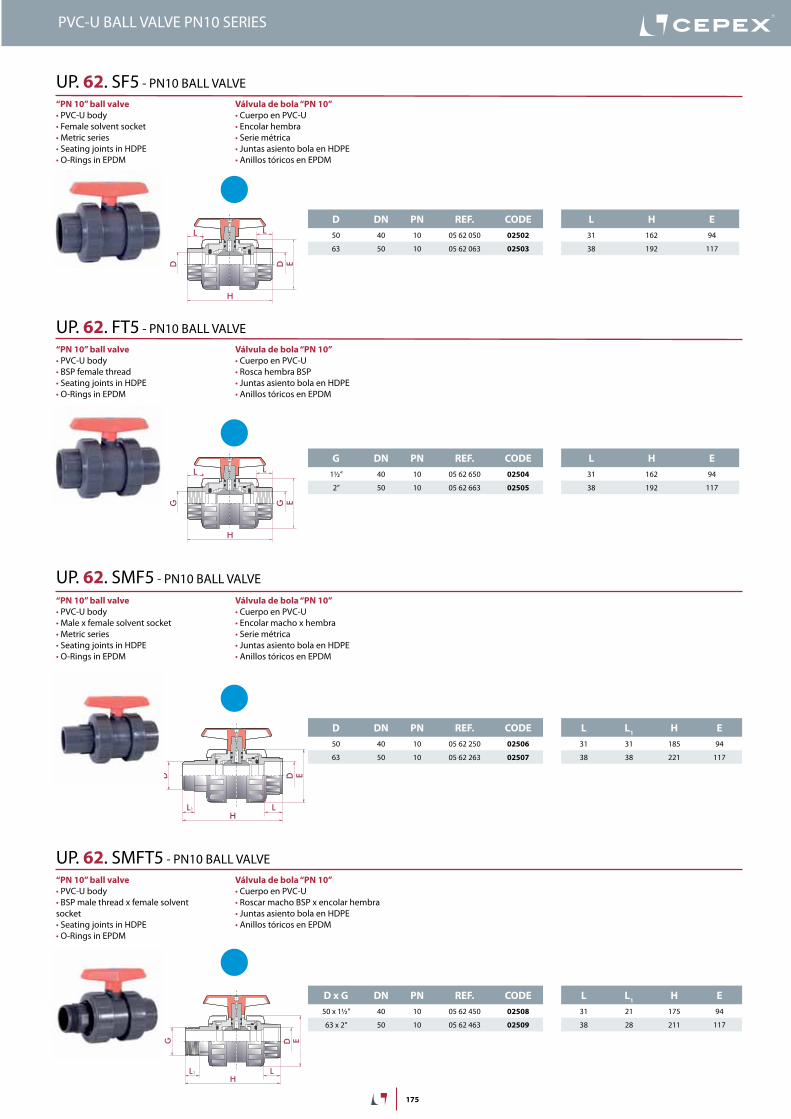
D DN PN REF. CODE50 40 10 05 62 050 02502
63 50 10 05 62 063 02503
L H E31 162 94
38 192 117
G DN PN REF. CODE1½” 40 10 05 62 650 02504
2” 50 10 05 62 663 02505
L H E31 162 94
38 192 117
D DN PN REF. CODE50 40 10 05 62 250 02506
63 50 10 05 62 263 02507
L L1 H E31 31 185 94
38 38 221 117
D x G DN PN REF. CODE50 x 1½” 40 10 05 62 450 02508
63 x 2” 50 10 05 62 463 02509
L L1 H E31 21 175 94
38 28 211 117
D D
H
E
L L
G G
H
E
L L
L
ED
L
H
D
1
Válvula de bola “PN 10”• Cuerpo en PVC-U• Encolar hembra• Serie métrica• Juntas asiento bola en HDPE• Anillos tóricos en EPDM
“PN 10” ball valve• PVC-U body• Female solvent socket• Metric series• Seating joints in HDPE• O-Rings in EPDM
UP. 62. SF5 - PN10 BALL VALVE
Válvula de bola “PN 10”• Cuerpo en PVC-U• Rosca hembra BSP• Juntas asiento bola en HDPE• Anillos tóricos en EPDM
“PN 10” ball valve• PVC-U body• BSP female thread• Seating joints in HDPE• O-Rings in EPDM
UP. 62. FT5 - PN10 BALL VALVE
Válvula de bola “PN 10”• Cuerpo en PVC-U• Encolar macho x hembra• Serie métrica• Juntas asiento bola en HDPE• Anillos tóricos en EPDM
“PN 10” ball valve• PVC-U body• Male x female solvent socket• Metric series• Seating joints in HDPE• O-Rings in EPDM
UP. 62. SMF5 - PN10 BALL VALVE
Válvula de bola “PN 10”• Cuerpo en PVC-U• Roscar macho BSP x encolar hembra • Juntas asiento bola en HDPE• Anillos tóricos en EPDM
“PN 10” ball valve• PVC-U body• BSP male thread x female solvent socket• Seating joints in HDPE• O-Rings in EPDM
UP. 62. SMFT5 - PN10 BALL VALVE
PVC-U BALL VALVE PN10 SERIES
176
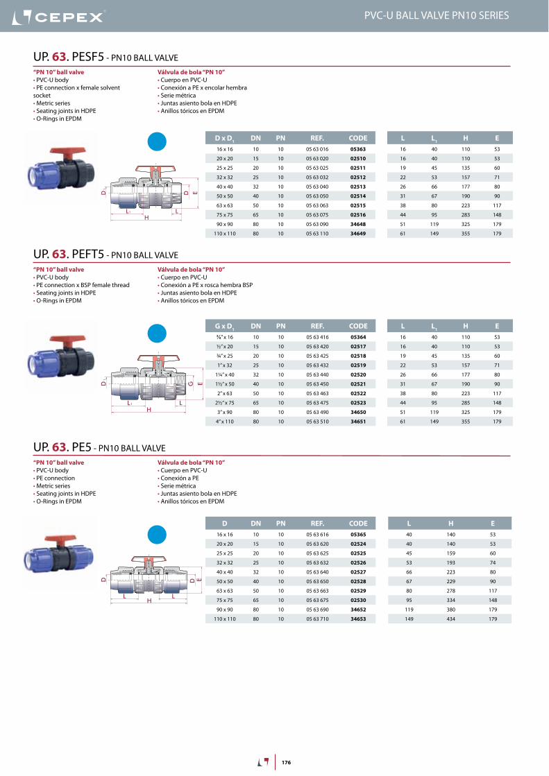
D x D1 DN PN REF. CODE16 x 16 10 10 05 63 016 05363
20 x 20 15 10 05 63 020 02510
25 x 25 20 10 05 63 025 02511
32 x 32 25 10 05 63 032 02512
40 x 40 32 10 05 63 040 02513
50 x 50 40 10 05 63 050 02514
63 x 63 50 10 05 63 063 02515
75 x 75 65 10 05 63 075 02516
90 x 90 80 10 05 63 090 34648
110 x 110 80 10 05 63 110 34649
L L1 H E16 40 110 53
16 40 110 53
19 45 135 60
22 53 157 71
26 66 177 80
31 67 190 90
38 80 223 117
44 95 283 148
51 119 325 179
61 149 355 179
G x D1 DN PN REF. CODE⅜” x 16 10 10 05 63 416 05364
½” x 20 15 10 05 63 420 02517
¾” x 25 20 10 05 63 425 02518
1” x 32 25 10 05 63 432 02519
1¼” x 40 32 10 05 63 440 02520
1½” x 50 40 10 05 63 450 02521
2” x 63 50 10 05 63 463 02522
2½” x 75 65 10 05 63 475 02523
3” x 90 80 10 05 63 490 34650
4” x 110 80 10 05 63 510 34651
L L1 H E16 40 110 53
16 40 110 53
19 45 135 60
22 53 157 71
26 66 177 80
31 67 190 90
38 80 223 117
44 95 285 148
51 119 325 179
61 149 355 179
D DN PN REF. CODE16 x 16 10 10 05 63 616 05365
20 x 20 15 10 05 63 620 02524
25 x 25 20 10 05 63 625 02525
32 x 32 25 10 05 63 632 02526
40 x 40 32 10 05 63 640 02527
50 x 50 40 10 05 63 650 02528
63 x 63 50 10 05 63 663 02529
75 x 75 65 10 05 63 675 02530
90 x 90 80 10 05 63 690 34652
110 x 110 80 10 05 63 710 34653
L H E40 140 53
40 140 53
45 159 60
53 193 74
66 223 80
67 229 90
80 278 117
95 334 148
119 380 179
149 434 179
LL
H
ED
1
1
D
LL
H
ED
1
1
G
LLH
ED D
Válvula de bola “PN 10”• Cuerpo en PVC-U• Conexión a PE x encolar hembra• Serie métrica• Juntas asiento bola en HDPE• Anillos tóricos en EPDM
“PN 10” ball valve• PVC-U body• PE connection x female solvent socket• Metric series• Seating joints in HDPE• O-Rings in EPDM
UP. 63. PESF5 - PN10 BALL VALVE
Válvula de bola “PN 10”• Cuerpo en PVC-U• Conexión a PE x rosca hembra BSP• Juntas asiento bola en HDPE• Anillos tóricos en EPDM
“PN 10” ball valve• PVC-U body• PE connection x BSP female thread• Seating joints in HDPE• O-Rings in EPDM
UP. 63. PEFT5 - PN10 BALL VALVE
Válvula de bola “PN 10”• Cuerpo en PVC-U• Conexión a PE• Serie métrica• Juntas asiento bola en HDPE• Anillos tóricos en EPDM
“PN 10” ball valve• PVC-U body• PE connection • Metric series• Seating joints in HDPE• O-Rings in EPDM
UP. 63. PE5 - PN10 BALL VALVE
PVC-U BALL VALVE PN10 SERIES
403
PVC-U BALL VALVE PN10 SERIES - BRITISH STANDARD
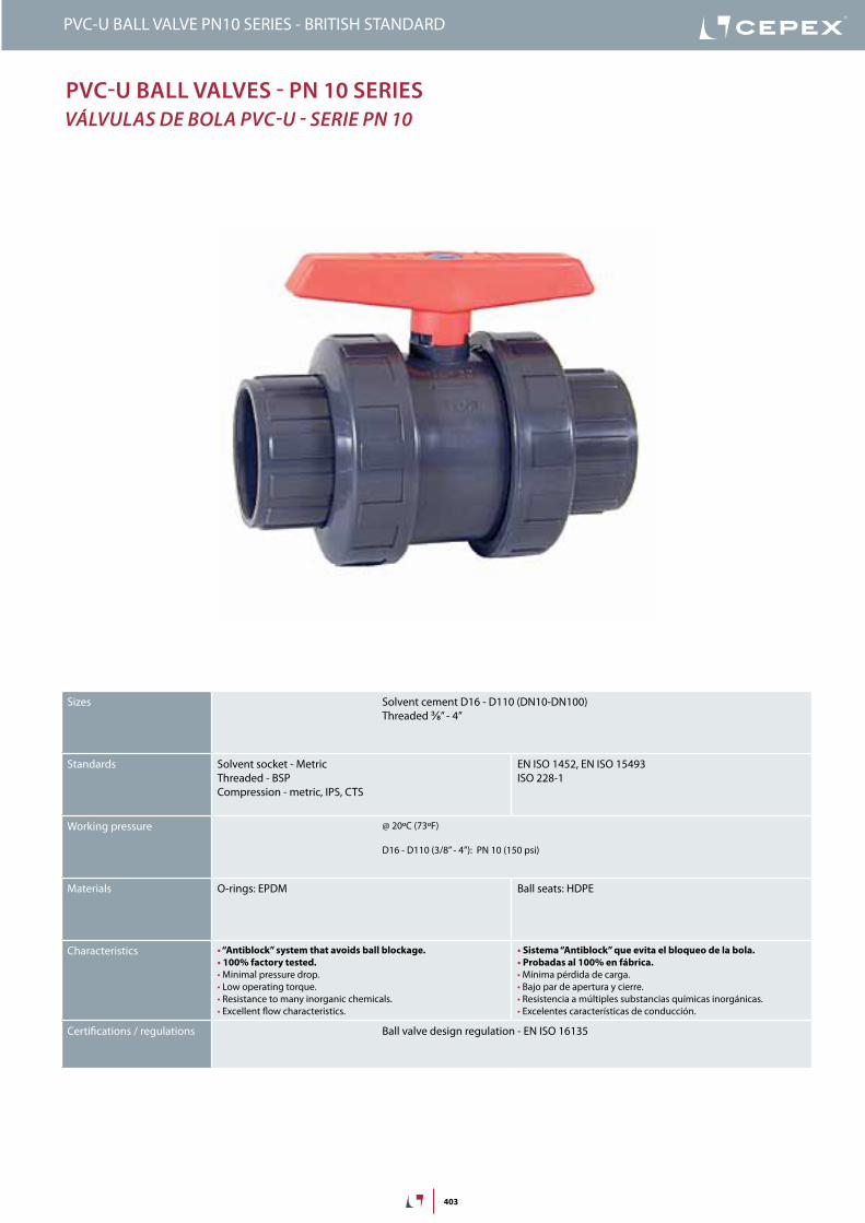
PVC-U Ball ValVes - Pn 10 series VálVulas de bola PVC-u - serie PN 10
Sizes Solvent cement D16 - D110 (DN10-DN100)Threaded ⅜” - 4”
Standards Solvent socket - MetricThreaded - BSPCompression - metric, IPS, CTS
EN ISO 1452, EN ISO 15493ISO 228-1
Working pressure @ 20ºC (73ºF)
D16 - D110 (3/8” - 4”): PN 10 (150 psi)
Materials O-rings: EPDM Ball seats: HDPE
Characteristics • “Antiblock” system that avoids ball blockage.• 100% factory tested.• Minimal pressure drop.• Low operating torque.• Resistance to many inorganic chemicals.• Excellent flow characteristics.
• Sistema “Antiblock” que evita el bloqueo de la bola.• Probadas al 100% en fábrica.• Mínima pérdida de carga.• Bajo par de apertura y cierre.• Resistencia a múltiples substancias químicas inorgánicas.• Excelentes características de conducción.
Certifications / regulations Ball valve design regulation - EN ISO 16135
404
FIG. Parts Despiece Material
1 Shaft Eje PVC-U
2 Ball Bola PVC-U
3 Union nut Tuerca PVC-U
4 Handle Conjunto maneta PP
5 End connector Manguito enlace PVC-U
6 Ball seat Asiento bola HDPE
7 Shaft o-ring Junta eje EPDM
8 Body o-ring Junta cuerpo EPDM
9 Dampener seal Junta amortiguación EPDM
10 End connector o-ring Junta manguito EPDM
11 Body Cuerpo PVC-U
12 Seal-carrier Portajuntas PVC-U
1
2
3
4
9
6
7
9
5
810
3
5
6
11
12
10
DN
40
-1½
”DN
50
-2”
0,1
10 (l/min)
bar
Kv (l/min , p = 1 bar)
0,01
0,001
1
100 1.000 10.000
(GPM)26,42 264 2.642
1,50
0,15
0,01
15,0
psi
Flow / Débit / Caudal / Caudal
Pres
sure
loss
/Per
tede
char
ge/
Pérd
ida
deca
rga
/Per
dasd
eca
rga
20 years / water flow20 années / fluide de l�eau20 años / fluido de agua20 anos / caudal de água
18
16
14
12
10
8
6
4
2
0
0 10 20 30 40 50 60
Temperature / Température / Temperatura / Temperatura
Pres
sure
/Pre
ssio
n/ P
resió
n/ P
ress
ão
°C32 50 68 86 104 122 140 °F
barpsi270
240
210
180
150
120
90
60
30
0
2,64
PN 10
PressUre / TeMPeraTUre GraPHdiaGraMa PresiÓN / TeMPeraTura
Pres
sure
/ Pr
esió
n
Temperature / Temperatura
Vida útil: 25 añosPresión hidrostática máxima que un com-ponente es capaz de soportar en servicio continuo (sin sobrepresión)
Life: 25 yearsHydrostatic maximum pressure a comp-nent may outstand in continous service (without overpressure)
PVC-U BALL VALVE PN10 SERIES - BRITISH STANDARD
405
PVC-U BALL VALVE PN10 SERIES - BRITISH STANDARD
DN
40
-1½
”DN
50
-2”
0,1
10 (l/min)
bar
Kv (l/min , p = 1 bar)
0,01
0,001
1
100 1.000 10.000
(GPM)26,42 264 2.642
1,50
0,15
0,01
15,0
psi
Flow / Débit / Caudal / Caudal
Pres
sure
loss
/Per
tede
char
ge/
Pérd
ida
deca
rga
/Per
dasd
eca
rga
20 years / water flow20 années / fluide de l�eau20 años / fluido de agua20 anos / caudal de água
18
16
14
12
10
8
6
4
2
0
0 10 20 30 40 50 60
Temperature / Température / Temperatura / Temperatura
Pres
sure
/Pre
ssio
n/ P
resió
n/ P
ress
ão
°C32 50 68 86 104 122 140 °F
barpsi270
240
210
180
150
120
90
60
30
0
2,64
PN 10
PressUre lOss DiaGraMdiaGraMa de PÉrdidas de CarGa
Pres
sure
loss
/ Pé
rdid
a de
carg
a
Flow / Caudal
Cv = Kv100 / 14,28Kv100 (l/min, ∆p = 1 bar)Cv (GPM, ∆p = 1 psi)
D 50-1½” 63-2”
DN 40 50
Kv100 1.600 3.000
Cv 112 210,1
relaTiVe FlOWFluJo relaTiVo
OPeraTiOnal TOrQUe CHarTTabla de Par de MaNiobra
Operating torque values at rated pressure (PN) and 20 °C in as new direct from the factory condition. Installation and operating condi-tions (pressure and temperature) will affect these values.
Los valores de par de giro se determinan a presión nominal (PN) y a 20 °C, en condiciones de salida de fábrica. Las condiciones de instalación y operación (presión y temperatura) afectarán a estos valores.
D 50-1½” 63-2”
DN 40 50
Nm 5 15
in·lbf 44,3 132,8
406
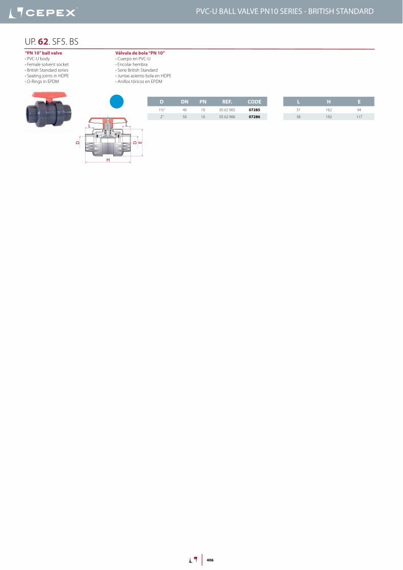
L H E31 162 94
38 192 117
D DN PN REF. CODE1½” 40 10 05 62 905 07285
2” 50 10 05 62 906 07286
D D
H
E
L L
Válvula de bola “PN 10”• Cuerpo en PVC-U• Encolar hembra• Serie British Standard• Juntas asiento bola en HDPE• Anillos tóricos en EPDM
“PN 10” ball valve• PVC-U body• Female solvent socket• British Standard series• Seating joints in HDPE• O-Rings in EPDM
UP. 62. SF5. BS
PVC-U BALL VALVE PN10 SERIES - BRITISH STANDARD
485
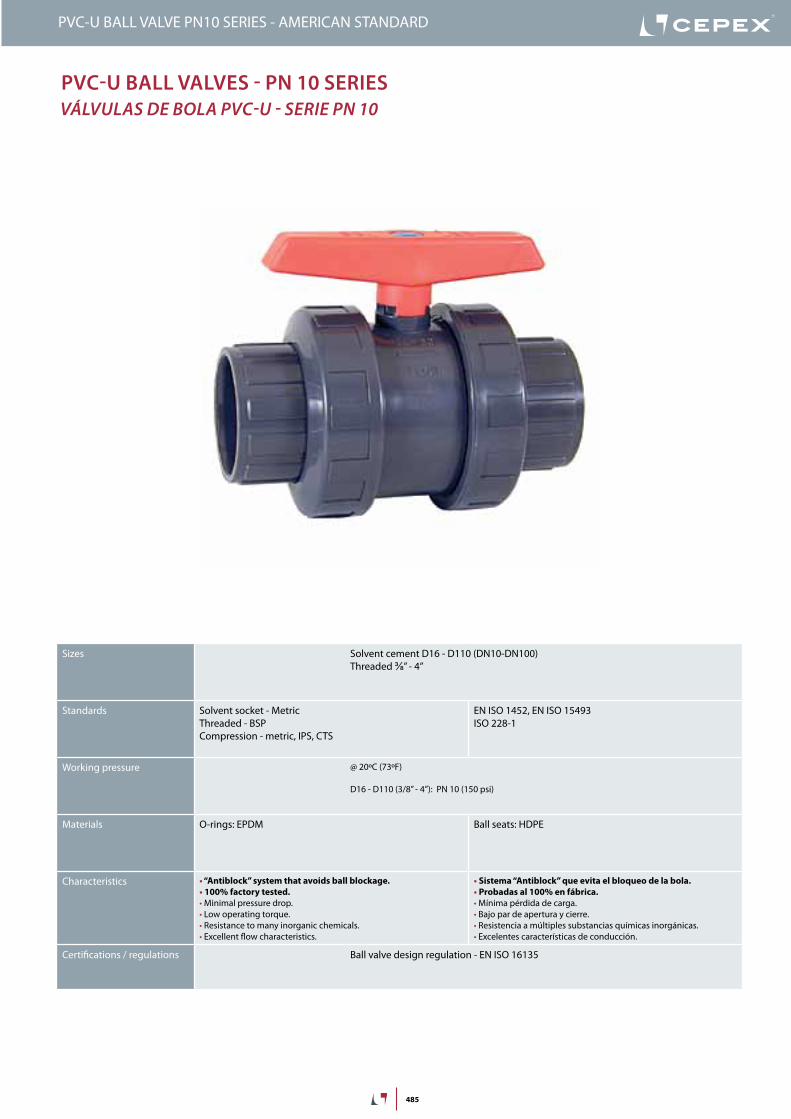
PVC-U Ball ValVes - Pn 10 series VálVulas de bola PVC-u - serie PN 10
PVC-U BALL VALVE PN10 SERIES - AMERICAN STANDARD
Sizes Solvent cement D16 - D110 (DN10-DN100)Threaded ⅜” - 4”
Standards Solvent socket - MetricThreaded - BSPCompression - metric, IPS, CTS
EN ISO 1452, EN ISO 15493ISO 228-1
Working pressure @ 20ºC (73ºF)
D16 - D110 (3/8” - 4”): PN 10 (150 psi)
Materials O-rings: EPDM Ball seats: HDPE
Characteristics • “Antiblock” system that avoids ball blockage.• 100% factory tested.• Minimal pressure drop.• Low operating torque.• Resistance to many inorganic chemicals.• Excellent flow characteristics.
• Sistema “Antiblock” que evita el bloqueo de la bola.• Probadas al 100% en fábrica.• Mínima pérdida de carga.• Bajo par de apertura y cierre.• Resistencia a múltiples substancias químicas inorgánicas.• Excelentes características de conducción.
Certifications / regulations Ball valve design regulation - EN ISO 16135
486
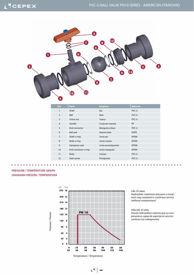
FIG. Parts Despiece Material
1 Shaft Eje PVC-U
2 Ball Bola PVC-U
3 Union nut Tuerca PVC-U
4 Handle Conjunto maneta PP
5 End connector Manguito enlace PVC-U
6 Ball seat Asiento bola HDPE
7 Shaft o-ring Junta eje EPDM
8 Body o-ring Junta cuerpo EPDM
9 Dampener seal Junta amortiguación EPDM
10 End connector o-ring Junta manguito EPDM
11 Body Cuerpo PVC-U
12 Seal-carrier Portajuntas PVC-U
1
2
3
4
9
6
7
9
5
810
3
5
6
11
12
10
DN
40
-1½
”DN
50
-2”
0,1
10 (l/min)
bar
Kv (l/min , p = 1 bar)
0,01
0,001
1
100 1.000 10.000
(GPM)26,42 264 2.642
1,50
0,15
0,01
15,0
psi
Flow / Débit / Caudal / Caudal
Pres
sure
loss
/Per
tede
char
ge/
Pérd
ida
deca
rga
/Per
dasd
eca
rga
20 years / water flow20 années / fluide de l�eau20 años / fluido de agua20 anos / caudal de água
18
16
14
12
10
8
6
4
2
0
0 10 20 30 40 50 60
Temperature / Température / Temperatura / Temperatura
Pres
sure
/Pre
ssio
n/ P
resió
n/ P
ress
ão
°C32 50 68 86 104 122 140 °F
barpsi270
240
210
180
150
120
90
60
30
0
2,64
PN 10
PressUre / TeMPeraTUre GraPHdiaGraMa PresiÓN / TeMPeraTura
Pres
sure
/ Pr
esió
n
Temperature / Temperatura
Vida útil: 25 añosPresión hidrostática máxima que un com-ponente es capaz de soportar en servicio continuo (sin sobrepresión)
Life: 25 yearsHydrostatic maximum pressure a comp-nent may outstand in continous service (without overpressure)
PVC-U BALL VALVE PN10 SERIES - AMERICAN STANDARD
487
PVC-U BALL VALVE PN10 SERIES - AMERICAN STANDARD
DN
40
-1½
”DN
50
-2”
0,1
10 (l/min)
bar
Kv (l/min , p = 1 bar)
0,01
0,001
1
100 1.000 10.000
(GPM)26,42 264 2.642
1,50
0,15
0,01
15,0
psi
Flow / Débit / Caudal / Caudal
Pres
sure
loss
/Per
tede
char
ge/
Pérd
ida
deca
rga
/Per
dasd
eca
rga
20 years / water flow20 années / fluide de l�eau20 años / fluido de agua20 anos / caudal de água
18
16
14
12
10
8
6
4
2
0
0 10 20 30 40 50 60
Temperature / Température / Temperatura / Temperatura
Pres
sure
/Pre
ssio
n/ P
resió
n/ P
ress
ão
°C32 50 68 86 104 122 140 °F
barpsi270
240
210
180
150
120
90
60
30
0
2,64
PN 10
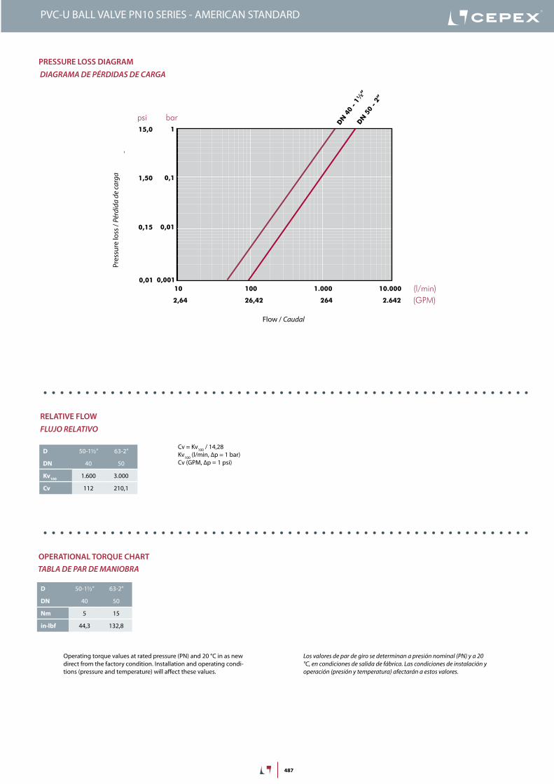
PressUre lOss DiaGraMdiaGraMa de PÉrdidas de CarGa
Pres
sure
loss
/ Pé
rdid
a de
carg
a
Flow / Caudal
Cv = Kv100 / 14,28Kv100 (l/min, ∆p = 1 bar)Cv (GPM, ∆p = 1 psi)
D 50-1½” 63-2”
DN 40 50
Kv100 1.600 3.000
Cv 112 210,1
relaTiVe FlOWFluJo relaTiVo
OPeraTiOnal TOrQUe CHarTTabla de Par de MaNiobra
Operating torque values at rated pressure (PN) and 20 °C in as new direct from the factory condition. Installation and operating condi-tions (pressure and temperature) will affect these values.
Los valores de par de giro se determinan a presión nominal (PN) y a 20 °C, en condiciones de salida de fábrica. Las condiciones de instalación y operación (presión y temperatura) afectarán a estos valores.
D 50-1½” 63-2”
DN 40 50
Nm 5 15
in·lbf 44,3 132,8
488
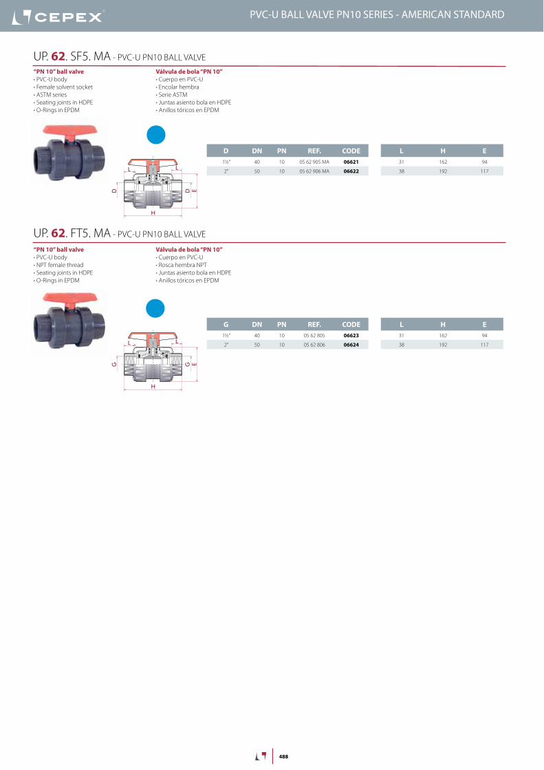
D DN PN REF. CODE1½” 40 10 05 62 905 MA 06621
2” 50 10 05 62 906 MA 06622
L H E31 162 94
38 192 117
G DN PN REF. CODE1½” 40 10 05 62 805 06623
2” 50 10 05 62 806 06624
L H E31 162 94
38 192 117
D D
H
E
L L
G G
H
E
L L
Válvula de bola “PN 10”• Cuerpo en PVC-U• Encolar hembra• Serie ASTM• Juntas asiento bola en HDPE• Anillos tóricos en EPDM
“PN 10” ball valve• PVC-U body• Female solvent socket• ASTM series• Seating joints in HDPE• O-Rings in EPDM
UP. 62. SF5. MA - PVC-U PN10 BALL VALVE
Válvula de bola “PN 10”• Cuerpo en PVC-U• Rosca hembra NPT• Juntas asiento bola en HDPE• Anillos tóricos en EPDM
“PN 10” ball valve• PVC-U body• NPT female thread• Seating joints in HDPE• O-Rings in EPDM
UP. 62. FT5. MA - PVC-U PN10 BALL VALVE
PVC-U BALL VALVE PN10 SERIES - AMERICAN STANDARD