Embed Size (px)
Citation preview
177
PVC-U BALL VALVES - UNIBLOCK SERIES
VÁLVULAS DE BOLA PVC-U - SERIE UNIBLOCK
Sizes Solvent cement D20 - D110 (DN15-DN100)Threaded ½” - 4”
Standards
Compression - metric, IPS, CTSISO 228-1, ASTM D 2464
Working pressure @ 20ºC (73ºF)
D20 - D110 (1/2” - 4”): PN 10 (150 psi)
Materials O-rings: EPDM
Characteristics “Antiblock” system that avoids ball blockage.
100% factory tested.
Low maintenance.
Fast replacement of O-Rings and ball seat without additional tools. Excellent flow characteristics. Easy to install. Light weight. Ideally suited for irrigation and swimming pools.
Sistema “Antiblock” que evita el bloqueo de la bola.
Probadas al 100% en fábrica.
Larga vida sin mantenimiento.
Reemplazo rápido de las juntas y de la junta de asiento de la bola sin herramientas adicionales. Excelentes características de conducción. Fácil de instalar. Ligera. Especialmente indicada para riego y piscina.
Certifications / regulations
NSF National Sanitation Foundation (USA)Only products bearing the NSF Mark are certifiedNSF 611½” thru 2” Socketed1½” thru 2” ThreadedASTM F1970
178
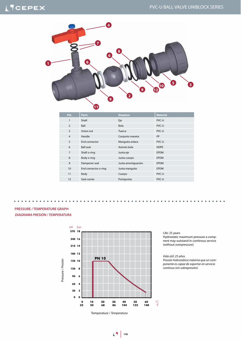
FIG. Parts Despiece Material
1 Shaft Eje PVC-U
2 PVC-U
3 Union nut Tuerca PVC-U
4 Handle Conjunto maneta PP
5 End connector Manguito enlace PVC-U
6 Asiento bola HDPE
7 Shaft o-ring Junta eje EPDM
8 Junta cuerpo EPDM
9 Dampener seal Junta amortiguación EPDM
10 End connector o-ring Junta manguito EPDM
11 Cuerpo PVC-U
12 Seal-carrier Portajuntas PVC-U
1
2
4
9
6
7
9
5
8
3
6
11
1210
20 years / w
20 années /
20 años / flu
20 anos / ca
18
16
14
12
10
8
6
4
2
0
0 10 20 30 40 50 60°C
32 50 68 86 104 122 140°F
bar
psi
270
240
210
180
150
120
90
60
30
0
PN 10
PRESSURE / TEMPERATURE GRAPH
DIAGRAMA PRESIÓN / TEMPERATURA
Pres
sure
/ Pr
esió
n
Temperature / Temperatura
Vida útil: 25 añosPresión hidrostática máxima que un com-ponente es capaz de soportar en servicio continuo (sin sobrepresión)
Life: 25 yearsHydrostatic maximum pressure a comp-nent may outstand in continous service (without overpressure)
179
DN15-½”
DN20-¾”
DN25-1”
DN32-1¼”
DN40-1½”
DN50-2”
DN65-2½”
0,1
10(l/min)
bar
0,01
0,001
1
100 1.000 10.000
DN80-3”
2,64(GPM)
26,4 264 2.642
1,50
0,15
0,01
15,0
psi
DN100-4”
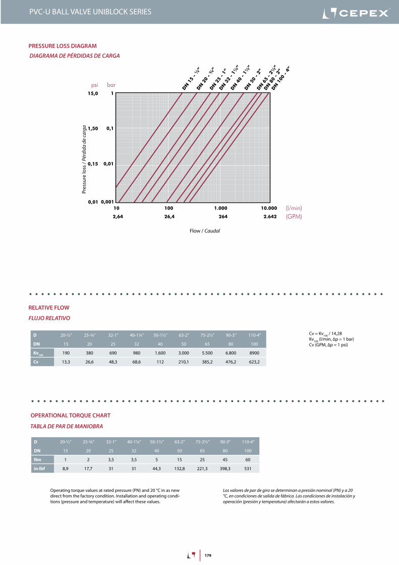
PRESSURE LOSS DIAGRAM
DIAGRAMA DE PÉRDIDAS DE CARGA
Pres
sure
loss
/ Pé
rdid
a de
carg
a
Flow / Caudal
100 / 14,28
100 (l/min, Δp = 1 bar)Cv (GPM, Δp = 1 psi)
D 20-½” 25-¾” 32-1” 40-1¼” 50-1½” 63-2” 75-2½” 90-3” 110-4”
DN 15 20 25 32 40 50 65 80 100
Kv100
190 380 690 980 1.600 3.000 5.500 6.800 8900
Cv 13,3 26,6 48,3 68,6 112 210,1 385,2 476,2 623,2
RELATIVE FLOW
FLUJO RELATIVO
OPERATIONAL TORQUE CHART
TABLA DE PAR DE MANIOBRA
Operating torque values at rated pressure (PN) and 20 °C in as new direct from the factory condition. Installation and operating condi-tions (pressure and temperature) will affect these values.
Los valores de par de giro se determinan a presión nominal (PN) y a 20 °C, en condiciones de salida de fábrica. Las condiciones de instalación y operación (presión y temperatura) afectarán a estos valores.
D 20-½” 25-¾” 32-1” 40-1¼” 50-1½” 63-2” 75-2½” 90-3” 110-4”
DN 15 20 25 32 40 50 65 80 100
Nm 1 2 3,5 3,5 5 15 25 45 60
in·lbf 8,9 17,7 31 31 44,3 132,8 221,3 398,3 531
180
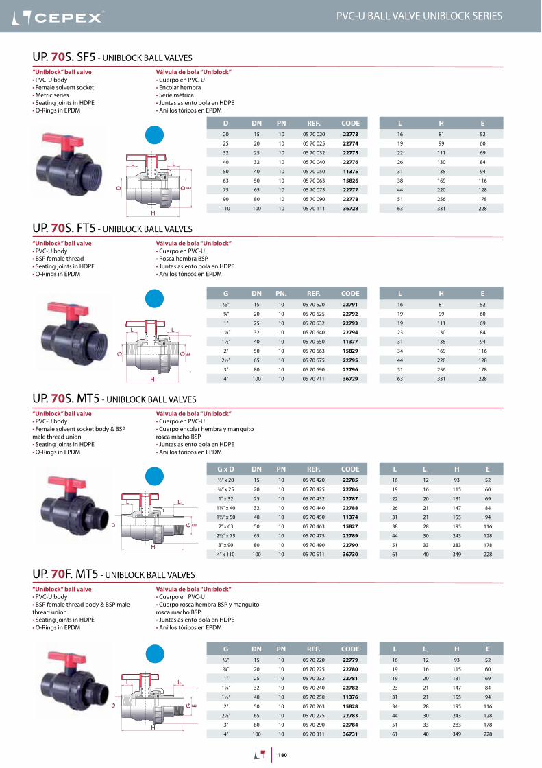
D DN PN REF. CODE
20 15 10 05 70 020 22773
25 20 10 05 70 025 22774
32 25 10 05 70 032 22775
40 32 10 05 70 040 22776
50 40 10 05 70 050 11375
63 50 10 05 70 063 15826
75 65 10 05 70 075 22777
90 80 10 05 70 090 22778
110 100 10 05 70 111 36728
L H E
16 81 52
19 99 60
22 111 69
26 130 84
31 135 94
38 169 116
44 220 128
51 256 178
63 331 228
G DN PN. REF. CODE
½” 15 10 05 70 620 22791
¾” 20 10 05 70 625 22792
1” 25 10 05 70 632 22793
1¼” 32 10 05 70 640 22794
1½” 40 10 05 70 650 11377
2” 50 10 05 70 663 15829
2½” 65 10 05 70 675 22795
3” 80 10 05 70 690 22796
4” 100 10 05 70 711 36729
L H E
16 81 52
19 99 60
19 111 69
23 130 84
31 135 94
34 169 116
44 220 128
51 256 178
63 331 228
G x D DN PN REF. CODE
½” x 20 15 10 05 70 420 22785
¾” x 25 20 10 05 70 425 22786
1” x 32 25 10 05 70 432 22787
1¼” x 40 32 10 05 70 440 22788
1½” x 50 40 10 05 70 450 11374
2” x 63 50 10 05 70 463 15827
2½” x 75 65 10 05 70 475 22789
3” x 90 80 10 05 70 490 22790
4” x 110 100 10 05 70 511 36730
L L1
H E
16 12 93 52
19 16 115 60
22 20 131 69
26 21 147 84
31 21 155 94
38 28 195 116
44 30 243 128
51 33 283 178
61 40 349 228
G DN PN REF. CODE
½” 15 10 05 70 220 22779
¾” 20 10 05 70 225 22780
1” 25 10 05 70 232 22781
1¼” 32 10 05 70 240 22782
1½” 40 10 05 70 250 11376
2” 50 10 05 70 263 15828
2½” 65 10 05 70 275 22783
3” 80 10 05 70 290 22784
4” 100 10 05 70 311 36731
L L1
H E
16 12 93 52
19 16 115 60
19 20 131 69
23 21 147 84
31 21 155 94
34 28 195 116
44 30 243 128
51 33 283 178
61 40 349 228
H
L
ED D
L
GG
H
L
E
L1
H
L L
G ED
1
H
L L
G EG
1
Válvula de bola “Uniblock”
Cuerpo en PVC-UEncolar hembraSerie métricaJuntas asiento bola en HDPEAnillos tóricos en EPDM
“Uniblock” ball valve
PVC-U bodyFemale solvent socketMetric seriesSeating joints in HDPEO-Rings in EPDM
UP. 70S. SF5
Válvula de bola “Uniblock”
Cuerpo en PVC-U
Juntas asiento bola en HDPEAnillos tóricos en EPDM
“Uniblock” ball valve
PVC-U body
Seating joints in HDPE O-Rings in EPDM
UP. 70S. FT5
Válvula de bola “Uniblock”
Cuerpo en PVC-UCuerpo encolar hembra y manguito
Juntas asiento bola en HDPEAnillos tóricos en EPDM
“Uniblock” ball valve
PVC-U body
male thread unionSeating joints in HDPEO-Rings in EPDM
UP. 70S. MT5
Válvula de bola “Uniblock”
Cuerpo en PVC-U
Juntas asiento bola en HDPEAnillos tóricos en EPDM
“Uniblock” ball valve
PVC-U body
thread unionSeating joints in HDPEO-Rings in EPDM
UP. 70F. MT5
181
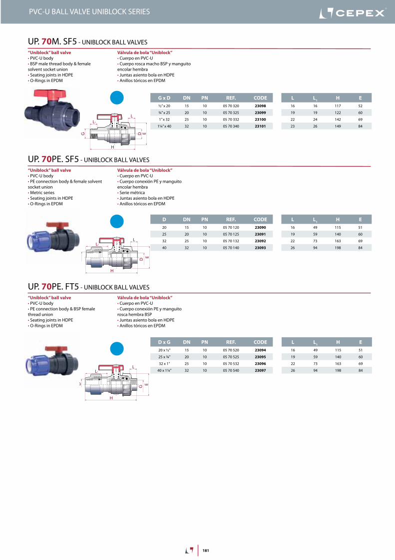
G x D DN PN REF. CODE
½” x 20 15 10 05 70 320 23098
¾” x 25 20 10 05 70 325 23099
1” x 32 25 10 05 70 332 23100
1¼” x 40 32 10 05 70 340 23101
L L1
H E
16 16 117 52
19 19 122 60
22 24 142 69
23 26 149 84
D DN PN REF. CODE
20 15 10 05 70 120 23090
25 20 10 05 70 125 23091
32 25 10 05 70 132 23092
40 32 10 05 70 140 23093
L L1
H E
16 49 115 51
19 59 140 60
22 73 163 69
26 94 198 84
D x G DN PN REF. CODE
20 x ½” 15 10 05 70 520 23094
25 x ¾” 20 10 05 70 525 23095
32 x 1” 25 10 05 70 532 23096
40 x 1¼” 32 10 05 70 540 23097
L L1
H E
16 49 115 51
19 59 140 60
22 73 163 69
26 94 198 84
G
L
L
H
E
1
D
Válvula de bola “Uniblock”
Cuerpo en PVC-U
encolar hembraJuntas asiento bola en HDPEAnillos tóricos en EPDM
“Uniblock” ball valve
PVC-U body
solvent socket unionSeating joints in HDPEO-Rings in EPDM
UP. 70M. SF5
Válvula de bola “Uniblock”
Cuerpo en PVC-U Cuerpo conexión PE y manguito
encolar hembra Serie métricaJuntas asiento bola en HDPEAnillos tóricos en EPDM
“Uniblock” ball valve
PVC-U body PE connection body & female solvent
socket unionMetric seriesSeating joints in HDPEO-Rings in EPDM
UP. 70PE. SF5
Válvula de bola “Uniblock”
Cuerpo en PVC-UCuerpo conexión PE y manguito
Juntas asiento bola en HDPEAnillos tóricos en EPDM
“Uniblock” ball valve
PVC-U body
thread unionSeating joints in HDPE O-Rings in EPDM
UP. 70PE. FT5
407
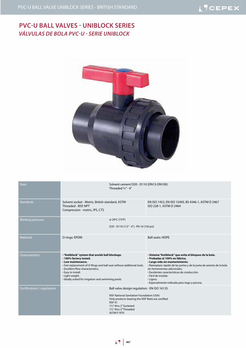
PVC-U BALL VALVES - UNIBLOCK SERIES
VÁLVULAS DE BOLA PVC-U - SERIE UNIBLOCK
Sizes Solvent cement D20 - D110 (DN15-DN100)Threaded ½” - 4”
Standards Solvent socket - Metric, British standard, ASTMThreaded - BSP, NPTCompression - metric, IPS, CTS
EN ISO 1452, EN ISO 15493, BS 4346-1, ASTM D 2467ISO 228-1, ASTM D 2464
Working pressure @ 20ºC (73ºF)
D20 - D110 (1/2” - 4”): PN 10 (150 psi)
Materials O-rings: EPDM Ball seats: HDPE
Characteristics “Antiblock” system that avoids ball blockage.
100% factory tested.
Low maintenance.
Fast replacement of O-Rings and ball seat without additional tools. Excellent flow characteristics. Easy to install. Light weight. Ideally suited for irrigation and swimming pools.
Sistema “Antiblock” que evita el bloqueo de la bola.
Probadas al 100% en fábrica.
Larga vida sin mantenimiento.
Reemplazo rápido de las juntas y de la junta de asiento de la bola sin herramientas adicionales. Excelentes características de conducción. Fácil de instalar. Ligera. Especialmente indicada para riego y piscina.
Certifications / regulations Ball valve design regulation - EN ISO 16135
NSF National Sanitation Foundation (USA)Only products bearing the NSF Mark are certifiedNSF 611½” thru 2” Socketed1½” thru 2” ThreadedASTM F1970
PVC-U BALL VALVE UNIBLOCK SERIES - BRITISH STANDARD
408
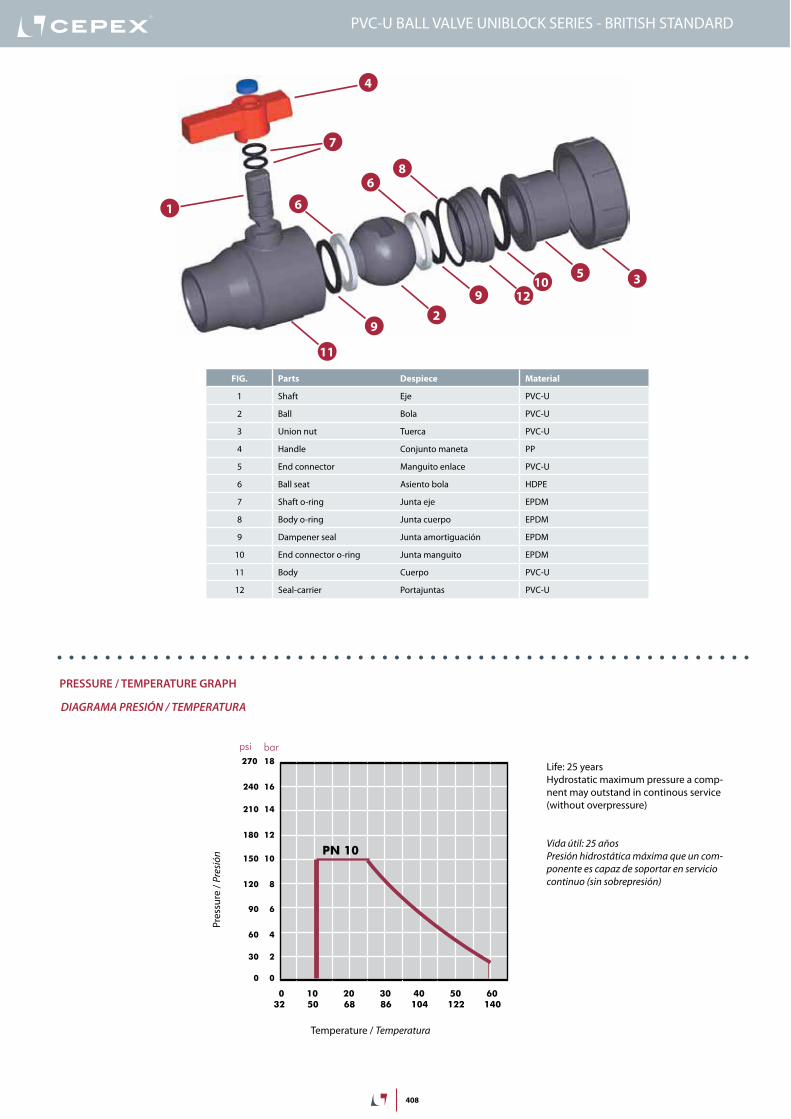
FIG. Parts Despiece Material
1 Shaft Eje PVC-U
2 Ball Bola PVC-U
3 Union nut Tuerca PVC-U
4 Handle Conjunto maneta PP
5 End connector Manguito enlace PVC-U
6 Ball seat Asiento bola HDPE
7 Shaft o-ring Junta eje EPDM
8 Body o-ring Junta cuerpo EPDM
9 Dampener seal Junta amortiguación EPDM
10 End connector o-ring Junta manguito EPDM
11 Body Cuerpo PVC-U
12 Seal-carrier Portajuntas PVC-U
1
2
4
9
6
7
9
5
8
3
6
11
1210
18
16
14
12
10
8
6
4
2
0
0 10 20 30 40 50 60
32 50 68 86 104 122 140
bar
psi
270
240
210
180
150
120
90
60
30
0
PN 10
PRESSURE / TEMPERATURE GRAPH
DIAGRAMA PRESIÓN / TEMPERATURA
Pres
sure
/ Pr
esió
n
Temperature / Temperatura
Vida útil: 25 añosPresión hidrostática máxima que un com-ponente es capaz de soportar en servicio continuo (sin sobrepresión)
Life: 25 yearsHydrostatic maximum pressure a comp-nent may outstand in continous service (without overpressure)
PVC-U BALL VALVE UNIBLOCK SERIES - BRITISH STANDARD
409
DN15-½”
DN20-¾”
DN25-1”
DN32-1¼”
DN40-1½”
DN50-2”
DN65-2½”
0,1
10(l/min)
bar
0,01
0,001
1
100 1.000 10.000
DN80-3”
2,64(GPM)
26,4 264 2.642
1,50
0,15
0,01
15,0
psi
DN100-4”
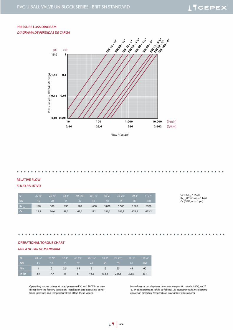
PRESSURE LOSS DIAGRAM
DIAGRAMA DE PÉRDIDAS DE CARGA
Pres
sure
loss
/ Pé
rdid
a de
carg
a
Flow / Caudal
Cv = Kv100 / 14,28Kv100 (l/min, Δp = 1 bar)Cv (GPM, Δp = 1 psi)
D 20-½” 25-¾” 32-1” 40-1¼” 50-1½” 63-2” 75-2½” 90-3” 110-4”
DN 15 20 25 32 40 50 65 80 100
Kv100
190 380 690 980 1.600 3.000 5.500 6.800 8900
Cv 13,3 26,6 48,3 68,6 112 210,1 385,2 476,2 623,2
RELATIVE FLOW
FLUJO RELATIVO
OPERATIONAL TORQUE CHART
TABLA DE PAR DE MANIOBRA
Operating torque values at rated pressure (PN) and 20 °C in as new direct from the factory condition. Installation and operating condi-tions (pressure and temperature) will affect these values.
Los valores de par de giro se determinan a presión nominal (PN) y a 20 °C, en condiciones de salida de fábrica. Las condiciones de instalación y operación (presión y temperatura) afectarán a estos valores.
D 20-½” 25-¾” 32-1” 40-1¼” 50-1½” 63-2” 75-2½” 90-3” 110-4”
DN 15 20 25 32 40 50 65 80 100
Nm 1 2 3,5 3,5 5 15 25 45 60
in·lbf 8,9 17,7 31 31 44,3 132,8 221,3 398,3 531
PVC-U BALL VALVE UNIBLOCK SERIES - BRITISH STANDARD
410
D DN PN REF. CODE
½” 15 10 05 70 901 27273
¾” 20 10 05 70 902 27274
1” 25 10 05 70 903 27275
1¼” 32 10 05 70 904 27276
1½” 40 10 05 70 905 16519
2” 50 10 05 70 906 16520
2½” 65 10 05 70 075M 22777
3” 80 10 05 70 908 27277
L H E
16 85 52
19 103 60
22 117 69
26 135 84
31 135 94
38 169 116
44 240 128
51 270 178
L L1
H E
16 12 97 52
19 16 119 60
22 20 137 69
26 21 152 84
31 21 155 94
38 28 195 116
44 30 263 128
51 33 297 178
H
L
ED DL
H
L L
G ED
1
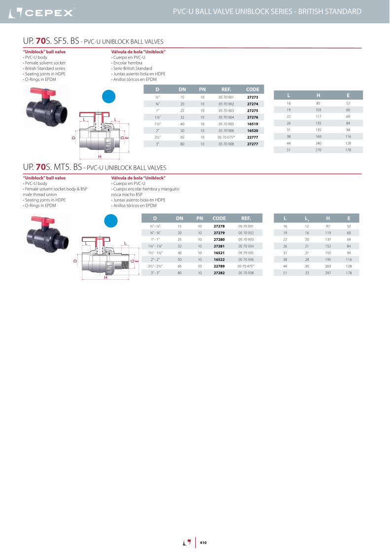
Válvula de bola “Uniblock”
Cuerpo en PVC-U
Encolar hembra
Serie British Standard
Juntas asiento bola en HDPE
Anillos tóricos en EPDM
“Uniblock” ball valve
PVC-U body
Female solvent socket
British Standard series
Seating joints in HDPE
O-Rings in EPDM
UP. 70S. SF5. BS - PVC-U UNIBLOCK BALL VALVES
Válvula de bola “Uniblock”
Cuerpo en PVC-U
Cuerpo encolar hembra y manguito
rosca macho BSP
Juntas asiento bola en HDPE
Anillos tóricos en EPDM
“Uniblock” ball valve
PVC-U body
Female solvent socket body & BSP
male thread union
Seating joints in HDPE
O-Rings in EPDM
UP. 70S. MT5. BS - PVC-U UNIBLOCK BALL VALVES
D DN PN CODE REF.
½” - ½” 15 10 27278 05 70 931
¾” - ¾” 20 10 27279 05 70 932
1” - 1” 25 10 27280 05 70 933
1¼” - 1¼” 32 10 27281 05 70 934
1½” - 1½” 40 10 16521 05 70 935
2” - 2” 50 10 16522 05 70 936
2½” - 2½” 65 10 22789 05 70 475M
3” - 3” 80 10 27282 05 70 938
PVC-U BALL VALVE UNIBLOCK SERIES - BRITISH STANDARD
489
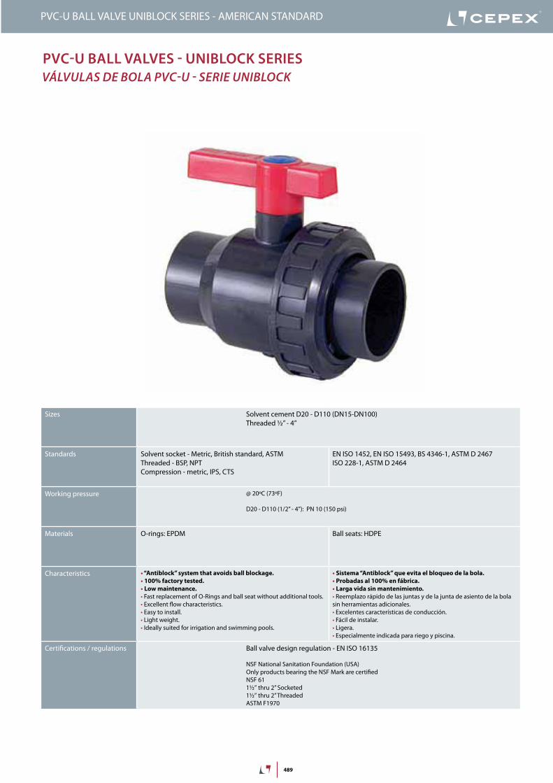
PVC-U BALL VALVES - UNIBLOCK SERIES
VÁLVULAS DE BOLA PVC-U - SERIE UNIBLOCK
PVC-U BALL VALVE UNIBLOCK SERIES - AMERICAN STANDARD
Sizes Solvent cement D20 - D110 (DN15-DN100)Threaded ½” - 4”
Standards Solvent socket - Metric, British standard, ASTMThreaded - BSP, NPTCompression - metric, IPS, CTS
EN ISO 1452, EN ISO 15493, BS 4346-1, ASTM D 2467ISO 228-1, ASTM D 2464
Working pressure @ 20ºC (73ºF)
D20 - D110 (1/2” - 4”): PN 10 (150 psi)
Materials O-rings: EPDM Ball seats: HDPE
Characteristics “Antiblock” system that avoids ball blockage.
100% factory tested.
Low maintenance.
Fast replacement of O-Rings and ball seat without additional tools. Excellent flow characteristics. Easy to install. Light weight. Ideally suited for irrigation and swimming pools.
Sistema “Antiblock” que evita el bloqueo de la bola.
Probadas al 100% en fábrica.
Larga vida sin mantenimiento.
Reemplazo rápido de las juntas y de la junta de asiento de la bola sin herramientas adicionales. Excelentes características de conducción. Fácil de instalar. Ligera. Especialmente indicada para riego y piscina.
Certifications / regulations Ball valve design regulation - EN ISO 16135
NSF National Sanitation Foundation (USA)Only products bearing the NSF Mark are certifiedNSF 611½” thru 2” Socketed1½” thru 2” ThreadedASTM F1970

490
FIG. Parts Despiece Material
1 Shaft Eje PVC-U
2 Ball Bola PVC-U
3 Union nut Tuerca PVC-U
4 Handle Conjunto maneta PP
5 End connector Manguito enlace PVC-U
6 Ball seat Asiento bola HDPE
7 Shaft o-ring Junta eje EPDM
8 Body o-ring Junta cuerpo EPDM
9 Dampener seal Junta amortiguación EPDM
10 End connector o-ring Junta manguito EPDM
11 Body Cuerpo PVC-U
12 Seal-carrier Portajuntas PVC-U
1
2
4
9
6
7
9
5
8
3
6
11
1210
18
16
14
12
10
8
6
4
2
0
0 10 20 30 40 50 60
32 50 68 86 104 122 140
bar
psi
270
240
210
180
150
120
90
60
30
0
PN 10
PVC-U BALL VALVE UNIBLOCK SERIES - AMERICAN STANDARD
PRESSURE / TEMPERATURE GRAPH
DIAGRAMA PRESIÓN / TEMPERATURA
Pres
sure
/ Pr
esió
n
Temperature / Temperatura
Vida útil: 25 añosPresión hidrostática máxima que un com-ponente es capaz de soportar en servicio continuo (sin sobrepresión)
Life: 25 yearsHydrostatic maximum pressure a comp-nent may outstand in continous service (without overpressure)
491
PVC-U BALL VALVE UNIBLOCK SERIES - AMERICAN STANDARD
DN15-½”
DN20-¾”
DN25-1”
DN32-1¼”
DN40-1½”
DN50-2”
DN65-2½”
0,1
10(l/min)
bar
0,01
0,001
1
100 1.000 10.000
DN80-3”
2,64(GPM)
26,4 264 2.642
1,50
0,15
0,01
15,0
psi
DN100-4”
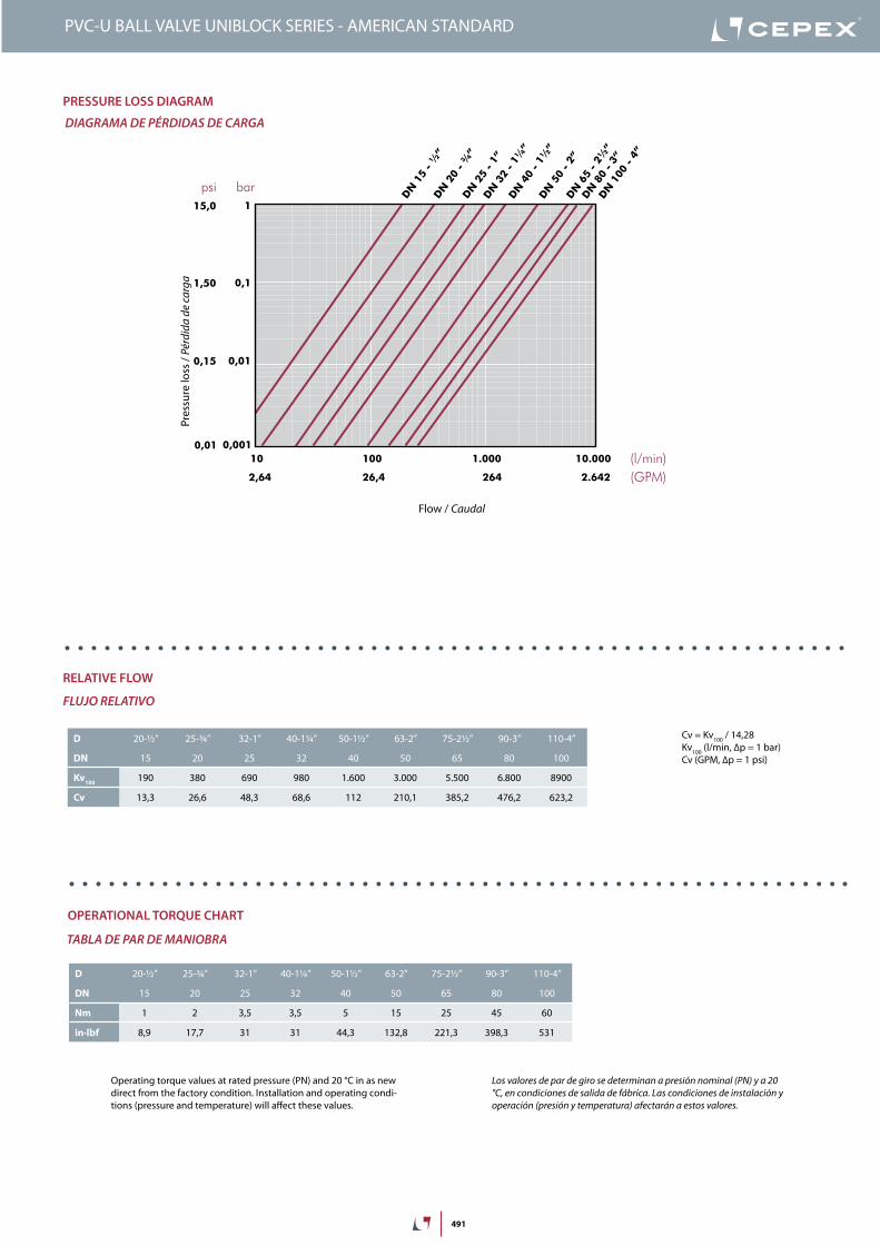
PRESSURE LOSS DIAGRAM
DIAGRAMA DE PÉRDIDAS DE CARGA
Pres
sure
loss
/ Pé
rdid
a de
carg
a
Flow / Caudal
Cv = Kv100 / 14,28Kv100 (l/min, Δp = 1 bar)Cv (GPM, Δp = 1 psi)
D 20-½” 25-¾” 32-1” 40-1¼” 50-1½” 63-2” 75-2½” 90-3” 110-4”
DN 15 20 25 32 40 50 65 80 100
Kv100
190 380 690 980 1.600 3.000 5.500 6.800 8900
Cv 13,3 26,6 48,3 68,6 112 210,1 385,2 476,2 623,2
RELATIVE FLOW
FLUJO RELATIVO
OPERATIONAL TORQUE CHART
TABLA DE PAR DE MANIOBRA
Operating torque values at rated pressure (PN) and 20 °C in as new direct from the factory condition. Installation and operating condi-tions (pressure and temperature) will affect these values.
Los valores de par de giro se determinan a presión nominal (PN) y a 20 °C, en condiciones de salida de fábrica. Las condiciones de instalación y operación (presión y temperatura) afectarán a estos valores.
D 20-½” 25-¾” 32-1” 40-1¼” 50-1½” 63-2” 75-2½” 90-3” 110-4”
DN 15 20 25 32 40 50 65 80 100
Nm 1 2 3,5 3,5 5 15 25 45 60
in·lbf 8,9 17,7 31 31 44,3 132,8 221,3 398,3 531
492
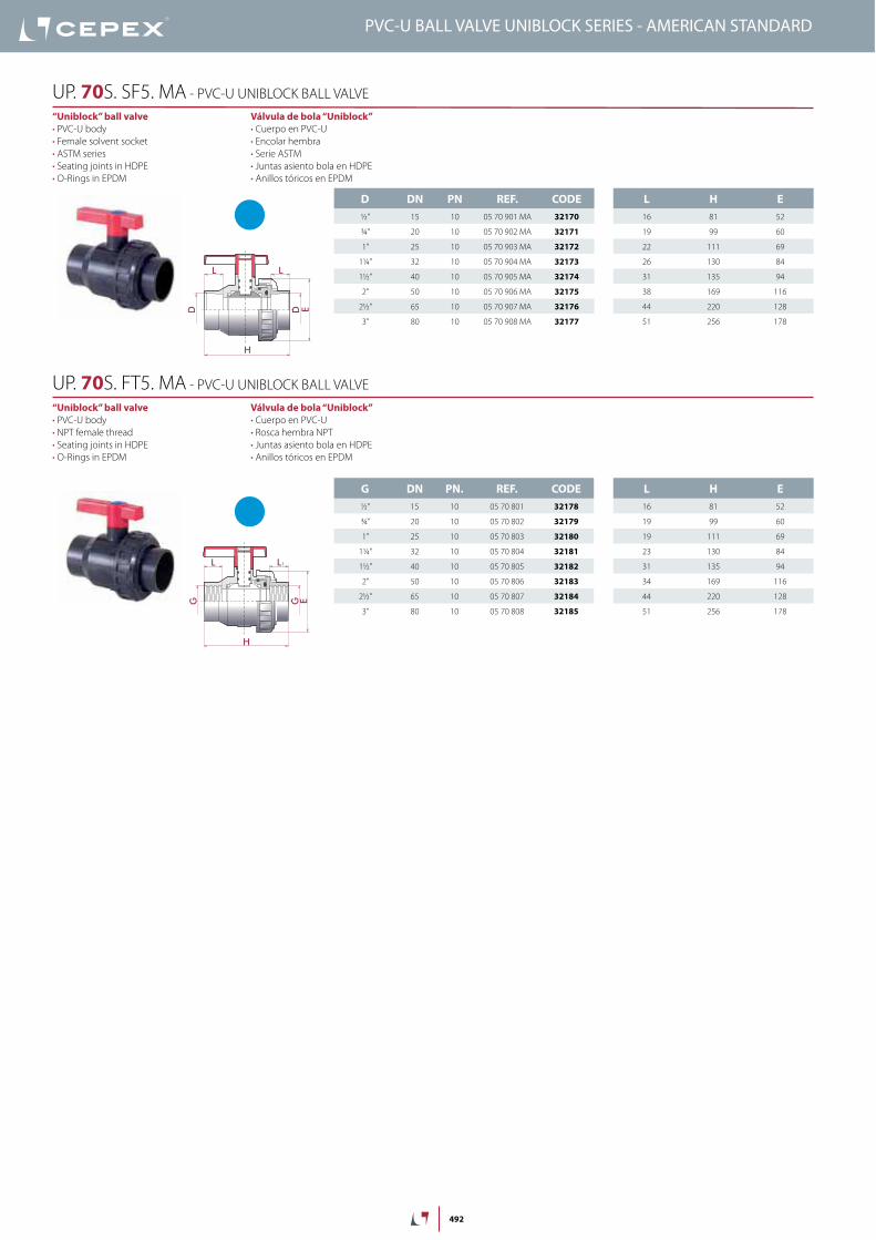
D DN PN REF. CODE
½” 15 10 05 70 901 MA 32170
¾” 20 10 05 70 902 MA 32171
1” 25 10 05 70 903 MA 32172
1¼” 32 10 05 70 904 MA 32173
1½” 40 10 05 70 905 MA 32174
2” 50 10 05 70 906 MA 32175
2½” 65 10 05 70 907 MA 32176
3” 80 10 05 70 908 MA 32177
L H E
16 81 52
19 99 60
22 111 69
26 130 84
31 135 94
38 169 116
44 220 128
51 256 178
G DN PN. REF. CODE
½” 15 10 05 70 801 32178
¾” 20 10 05 70 802 32179
1” 25 10 05 70 803 32180
1¼” 32 10 05 70 804 32181
1½” 40 10 05 70 805 32182
2” 50 10 05 70 806 32183
2½” 65 10 05 70 807 32184
3” 80 10 05 70 808 32185
L H E
16 81 52
19 99 60
19 111 69
23 130 84
31 135 94
34 169 116
44 220 128
51 256 178
H
L
ED D
L
GG
H
L
E
L1
Válvula de bola “Uniblock”
Cuerpo en PVC-U
Encolar hembra
Serie ASTM
Juntas asiento bola en HDPE
Anillos tóricos en EPDM
“Uniblock” ball valve
PVC-U body
Female solvent socket
ASTM series
Seating joints in HDPE
O-Rings in EPDM
UP. 70S. SF5. MA - PVC-U UNIBLOCK BALL VALVE
Válvula de bola “Uniblock”
Cuerpo en PVC-U
Rosca hembra NPT
Juntas asiento bola en HDPE
Anillos tóricos en EPDM
“Uniblock” ball valve
PVC-U body
NPT female thread
Seating joints in HDPE
O-Rings in EPDM
UP. 70S. FT5. MA - PVC-U UNIBLOCK BALL VALVE
PVC-U BALL VALVE UNIBLOCK SERIES - AMERICAN STANDARD
493
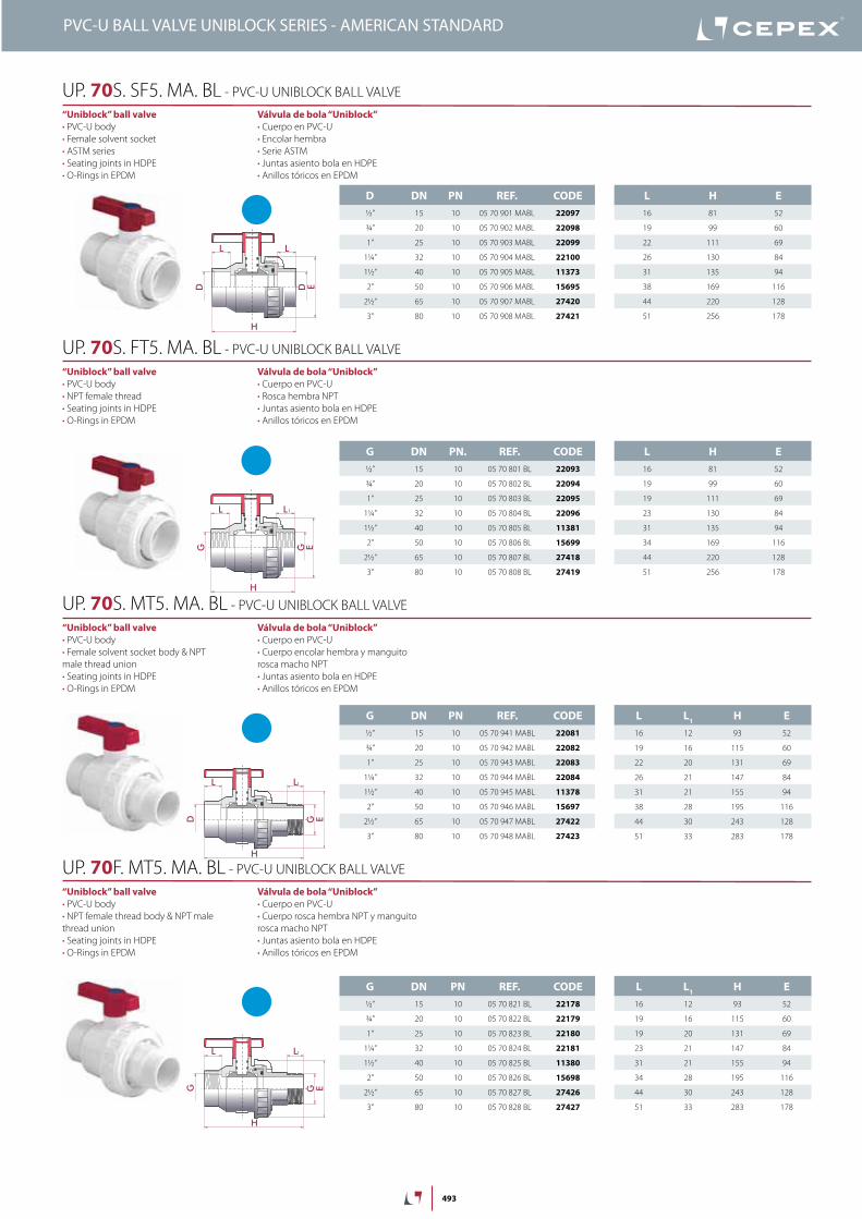
D DN PN REF. CODE
½” 15 10 05 70 901 MABL 22097
¾” 20 10 05 70 902 MABL 22098
1” 25 10 05 70 903 MABL 22099
1¼” 32 10 05 70 904 MABL 22100
1½” 40 10 05 70 905 MABL 11373
2” 50 10 05 70 906 MABL 15695
2½” 65 10 05 70 907 MABL 27420
3” 80 10 05 70 908 MABL 27421
L H E
16 81 52
19 99 60
22 111 69
26 130 84
31 135 94
38 169 116
44 220 128
51 256 178
G DN PN. REF. CODE
½” 15 10 05 70 801 BL 22093
¾” 20 10 05 70 802 BL 22094
1” 25 10 05 70 803 BL 22095
1¼” 32 10 05 70 804 BL 22096
1½” 40 10 05 70 805 BL 11381
2” 50 10 05 70 806 BL 15699
2½” 65 10 05 70 807 BL 27418
3” 80 10 05 70 808 BL 27419
L H E
16 81 52
19 99 60
19 111 69
23 130 84
31 135 94
34 169 116
44 220 128
51 256 178
G DN PN REF. CODE
½” 15 10 05 70 941 MABL 22081
¾” 20 10 05 70 942 MABL 22082
1” 25 10 05 70 943 MABL 22083
1¼” 32 10 05 70 944 MABL 22084
1½” 40 10 05 70 945 MABL 11378
2” 50 10 05 70 946 MABL 15697
2½” 65 10 05 70 947 MABL 27422
3” 80 10 05 70 948 MABL 27423
L L1
H E
16 12 93 52
19 16 115 60
22 20 131 69
26 21 147 84
31 21 155 94
38 28 195 116
44 30 243 128
51 33 283 178
G DN PN REF. CODE
½” 15 10 05 70 821 BL 22178
¾” 20 10 05 70 822 BL 22179
1” 25 10 05 70 823 BL 22180
1¼” 32 10 05 70 824 BL 22181
1½” 40 10 05 70 825 BL 11380
2” 50 10 05 70 826 BL 15698
2½” 65 10 05 70 827 BL 27426
3” 80 10 05 70 828 BL 27427
L L1
H E
16 12 93 52
19 16 115 60
19 20 131 69
23 21 147 84
31 21 155 94
34 28 195 116
44 30 243 128
51 33 283 178
H
L
ED D
L
GG
H
L
E
L1
H
L L
G ED
1
H
L L
G EG
1
Válvula de bola “Uniblock”
Cuerpo en PVC-U
Encolar hembra
Serie ASTM
Juntas asiento bola en HDPE
Anillos tóricos en EPDM
“Uniblock” ball valve
PVC-U body
Female solvent socket
ASTM series
Seating joints in HDPE
O-Rings in EPDM
UP. 70S. SF5. MA. BL - PVC-U UNIBLOCK BALL VALVE
Válvula de bola “Uniblock”
Cuerpo en PVC-U
Rosca hembra NPT
Juntas asiento bola en HDPE
Anillos tóricos en EPDM
“Uniblock” ball valve
PVC-U body
NPT female thread
Seating joints in HDPE
O-Rings in EPDM
UP. 70S. FT5. MA. BL - PVC-U UNIBLOCK BALL VALVE
Válvula de bola “Uniblock”
Cuerpo en PVC-U
Cuerpo encolar hembra y manguito
rosca macho NPT
Juntas asiento bola en HDPE
Anillos tóricos en EPDM
“Uniblock” ball valve
PVC-U body
Female solvent socket body & NPT
male thread union
Seating joints in HDPE
O-Rings in EPDM
UP. 70S. MT5. MA. BL - PVC-U UNIBLOCK BALL VALVE
Válvula de bola “Uniblock”
Cuerpo en PVC-U
Cuerpo rosca hembra NPT y manguito
rosca macho NPT
Juntas asiento bola en HDPE
Anillos tóricos en EPDM
“Uniblock” ball valve
PVC-U body
NPT female thread body & NPT male
thread union
Seating joints in HDPE
O-Rings in EPDM
UP. 70F. MT5. MA. BL - PVC-U UNIBLOCK BALL VALVE
PVC-U BALL VALVE UNIBLOCK SERIES - AMERICAN STANDARD


![INDEX PVC-U BALL VALVES BALL VALVES … · 135 ball valves vÁlvulas de bola 01 industrial series [std] series standard series connectit system e-qua series pn10 series uniblock series](https://img.pdfslide.net/doc/110x75/5bb23b8209d3f2e82b8c356e/index-pvc-u-ball-valves-ball-valves-135-ball-valves-valvulas-de-bola-01-industrial.jpg)