Embed Size (px)
Citation preview
Tra
nsfo
rmin
g E
xtre
miti
es™
PyroTITAN™ Humeral Resurfacing Arthroplasty
surgical technique
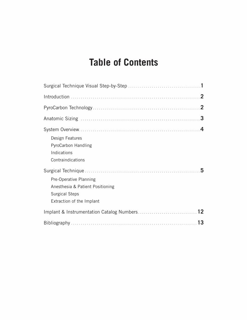
Table of Contents
Surgical Technique Visual Step-by-Step . . . . . . . . . . . . . . . . . . . . . . . . . . . . . . . . . . . . .1
Introduction . . . . . . . . . . . . . . . . . . . . . . . . . . . . . . . . . . . . . . . . . . . . . . . . . . . . . . . . . . . . . . . . . .2
PyroCarbon Technology . . . . . . . . . . . . . . . . . . . . . . . . . . . . . . . . . . . . . . . . . . . . . . . . . . . . . . .2
Anatomic Sizing . . . . . . . . . . . . . . . . . . . . . . . . . . . . . . . . . . . . . . . . . . . . . . . . . . . . . . . . . . . . .3
System Overview . . . . . . . . . . . . . . . . . . . . . . . . . . . . . . . . . . . . . . . . . . . . . . . . . . . . . . . . . . . . . .4
Design Features
PyroCarbon Handling
Indications
Contraindications
Surgical Technique . . . . . . . . . . . . . . . . . . . . . . . . . . . . . . . . . . . . . . . . . . . . . . . . . . . . . . . . . . .5
Pre-Operative Planning
Anesthesia & Patient Positioning
Surgical Steps
Extraction of the Implant
Implant & Instrumentation Catalog Numbers . . . . . . . . . . . . . . . . . . . . . . . . . . . . . . 12
Bibliography . . . . . . . . . . . . . . . . . . . . . . . . . . . . . . . . . . . . . . . . . . . . . . . . . . . . . . . . . . . . . . . . 13
surg
ical
tec
hniq
ue
Pyr
oTIT
AN
Hum
eral
Res
urfa
cing
Art
hrop
last
y
1
ONE: ACCESS & INCISION TWO: APPROACH
THREE: SIZING HUMERAL HEAD FOUR: CENTRALIZATION OF GUIDE PIN
FIVE: SHAPING HEAD
EIGHT: INSERTION OF IMPLANTSEVEN: BROACHING
PyroTITAN™ SURGICAL TECHNIQUE VISUAL STEP-BY-STEP
SIX: TRIALING
2
surg
ical
tec
hniq
ue
Pyr
oTIT
AN
Hum
eral
Res
urfa
cing
Art
hrop
last
y
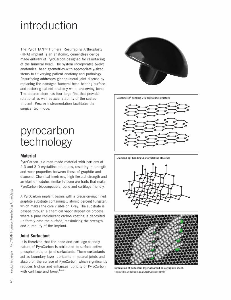
introduction The PyroTITAN™ Humeral Resurfacing Arthroplasty (HRA) implant is an anatomic, cementless device made entirely of PyroCarbon designed for resurfacing of the humeral head. The system incorporates twelve anatomical head geometries with appropriately-sized stems to fit varying patient anatomy and pathology. Resurfacing addresses glenohumeral joint disease by replacing the damaged humeral head bearing surface and restoring patient anatomy while preserving bone. The tapered stem has four large fins that provide rotational as well as axial stability of the seated implant. Precise instrumentation facilitates the surgical technique.
pyrocarbon technologyMaterialPyroCarbon is a man-made material with portions of 2-D and 3-D crystalline structures, resulting in strength and wear properties between those of graphite and diamond. Chemical inertness, high flexural strength and an elastic modulus similar to bone are traits that make PyroCarbon biocompatible, bone and cartilage friendly.
A PyroCarbon implant begins with a precision-machined graphite substrate containing 1 atomic percent tungsten, which makes the core visible on X-ray. The substrate is passed through a chemical vapor deposition process, where a pure radiolucent carbon coating is deposited uniformly onto the surface, maximizing the strength and durability of the implant.
Joint SurfactantIt is theorized that the bone and cartilage friendly nature of PyroCarbon is attributed to surface-active phospholipids, or joint surfactants. These surfactants act as boundary layer lubricants in natural joints and absorb on the surface of PyroCarbon, which significantly reduces friction and enhances lubricity of PyroCarbon with cartilage and bone.1,2,3
Graphite sp2 bonding 2-D crystalline structure
Simulation of surfactant layer absorbed on a graphite sheet.(http://ikc.unileoben.ac.at/ResCont5b.html)
Diamond sp2 bonding 3-D crystalline structure
surg
ical
tec
hniq
ue
Pyr
oTIT
AN
Hum
eral
Res
urfa
cing
Art
hrop
last
y
3
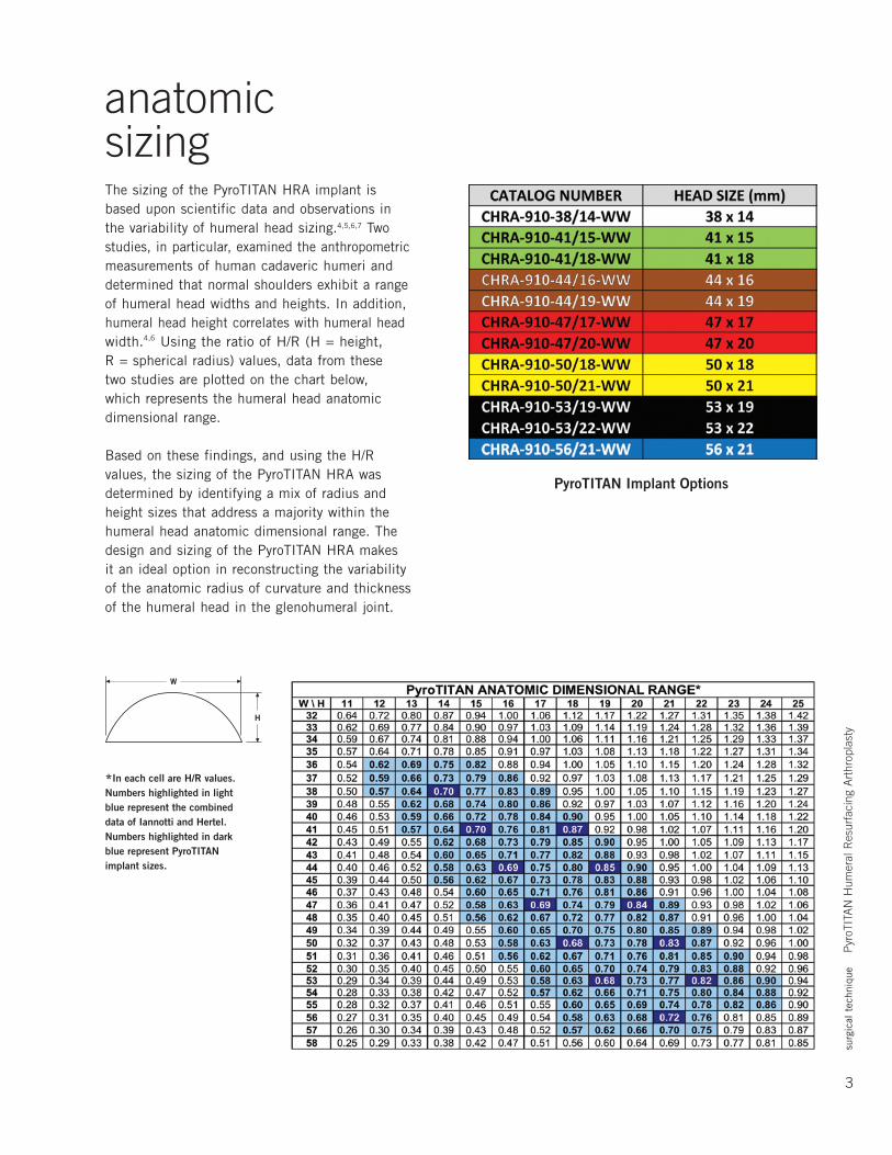
anatomic sizingThe sizing of the PyroTITAN HRA implant is based upon scientific data and observations in the variability of humeral head sizing.4,5,6,7 Two studies, in particular, examined the anthropometric measurements of human cadaveric humeri and determined that normal shoulders exhibit a range of humeral head widths and heights. In addition, humeral head height correlates with humeral head width.4,6 Using the ratio of H/R (H = height, R = spherical radius) values, data from these two studies are plotted on the chart below, which represents the humeral head anatomic dimensional range.
Based on these findings, and using the H/R values, the sizing of the PyroTITAN HRA was determined by identifying a mix of radius and height sizes that address a majority within the humeral head anatomic dimensional range. The design and sizing of the PyroTITAN HRA makes it an ideal option in reconstructing the variability of the anatomic radius of curvature and thickness of the humeral head in the glenohumeral joint.
*In each cell are H/R values. Numbers highlighted in light blue represent the combined data of Iannotti and Hertel. Numbers highlighted in dark blue represent PyroTITAN implant sizes.
PyroTITAN Implant Options
4
surg
ical
tec
hniq
ue
Pyr
oTIT
AN
Hum
eral
Res
urfa
cing
Art
hrop
last
y
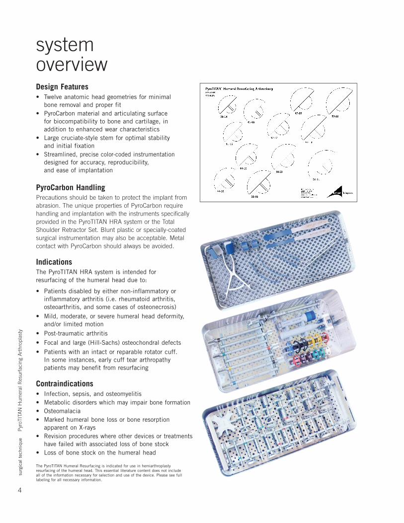
system overviewDesign Features• Twelve anatomic head geometries for minimal
bone removal and proper fit• PyroCarbonmaterialandarticulatingsurface
for biocompatibility to bone and cartilage, in addition to enhanced wear characteristics
• Largecruciate-stylestemforoptimalstability and initial fixation
• Streamlined,precisecolor-codedinstrumentationdesigned for accuracy, reproducibility, and ease of implantation
PyroCarbon HandlingPrecautions should be taken to protect the implant from abrasion. The unique properties of PyroCarbon require handling and implantation with the instruments specifically provided in the PyroTITAN HRA system or the Total Shoulder Retractor Set. Blunt plastic or specially-coated surgical instrumentation may also be acceptable. Metal contact with PyroCarbon should always be avoided.
IndicationsThe PyroTITAN HRA system is intended for resurfacing of the humeral head due to:
• Patients disabled by either non-inflammatory or inflammatory arthritis (i.e. rheumatoid arthritis, osteoarthritis, and some cases of osteonecrosis)
• Mild,moderate,orseverehumeralheaddeformity,and/or limited motion
• Post-traumaticarthritis• Focal and large (Hill-Sachs) osteochondral defects• Patientswithanintactorreparablerotatorcuff.
In some instances, early cuff tear arthropathy patients may benefit from resurfacing
Contraindications• Infection, sepsis, and osteomyelitis• Metabolicdisorderswhichmayimpairboneformation• Osteomalacia• Markedhumeralbonelossorboneresorption
apparent on X-rays• Revisionprocedureswhereotherdevicesortreatments
have failed with associated loss of bone stock• Lossofbonestockonthehumeralhead
The PyroTITAN Humeral Resurfacing is indicated for use in hemiarthroplasty resurfacing of the humeral head. This essential literature content does not include all of the information necessary for selection and use of the device. Please see full labeling for all necessary information.
surg
ical
tec
hniq
ue
Pyr
oTIT
AN
Hum
eral
Res
urfa
cing
Art
hrop
last
y
5
surgical techniqueRecognizing that a successful shoulder arthroplasty is critically dependent on soft tissue balancing, this document provides a detailed surgical exposure.
Pre-Operative PlanningTemplate the X-rays to select the appropriately sized implant (be wary of varying radiographic magnifications). Humeral head size is verified intra-operatively by measuring the head after osteophyte removal, if present.
Anesthesia and Patient PositioningProximal humeral resurfacing using the PyroTITAN implant can be performed using general anesthesia, regional anesthesia (i.e., interscalene block), or a combination of the two.
Place the patient in beach chair position (see right). Ensure that the involved shoulder extends laterally over the top corner of the table so that the arm can be brought into extension and adduction, which is essential for good exposure of the humeral head.
Step 1: Access and IncisionDepending on surgeon preference, either the deltopectoral or the anterosuperior approach (commonly known as Mackenzie)canbeused.
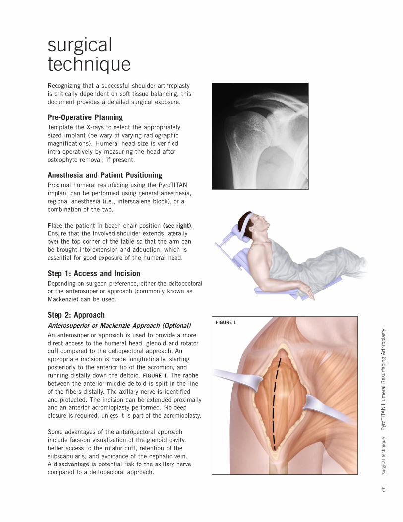
Step 2: ApproachAnterosuperior or Mackenzie Approach (Optional)An anterosuperior approach is used to provide a more direct access to the humeral head, glenoid and rotator cuff compared to the deltopectoral approach. An appropriate incision is made longitudinally, starting posteriorly to the anterior tip of the acromion, and running distally down the deltoid. FIGURE 1. The raphe between the anterior middle deltoid is split in the line of the fibers distally. The axillary nerve is identified and protected. The incision can be extended proximally and an anterior acromioplasty performed. No deep closure is required, unless it is part of the acromioplasty.
Some advantages of the anteropectoral approach include face-on visualization of the glenoid cavity, better access to the rotator cuff, retention of the subscapularis, and avoidance of the cephalic vein. A disadvantage is potential risk to the axillary nerve compared to a deltopectoral approach.
FIGURE 1
6
surg
ical
tec
hniq
ue
Pyr
oTIT
AN
Hum
eral
Res
urfa
cing
Art
hrop
last
y
Deltopectoral ApproachSince the deltopectoral approach is the most typical approach for this procedure, the surgical technique will highlight this approach only. The advantages of the deltopectoral approach include preservation of the deltoid origin and insertion, utilization of an extensile exposure, and internervous plane.
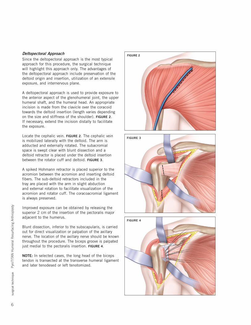
A deltopectoral approach is used to provide exposure to the anterior aspect of the glenohumeral joint, the upper humeral shaft, and the humeral head. An appropriate incision is made from the clavicle over the coracoid towards the deltoid insertion (length varies depending on the size and stiffness of the shoulder). FIGURE 2. If necessary, extend the incision distally to facilitate the exposure.
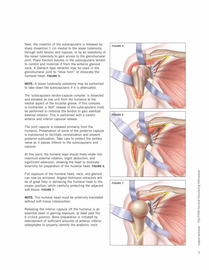
Locatethecephalicvein.FIGURE 2. The cephalic vein is mobilized laterally with the deltoid. The arm is adducted and externally rotated. The subacromial space is swept clear with blunt dissection and a deltoid retractor is placed under the deltoid insertion between the rotator cuff and deltoid. FIGURE 3.
A spiked Hohmann retractor is placed superior to the acromion between the acromion and inserting deltoid fibers. The sub-deltoid retractors included in the tray are placed with the arm in slight abduction and external rotation to facilitate visualization of the acromion and rotator cuff. The coracoacromial ligament is always preserved.
Improved exposure can be obtained by releasing the superior 2 cm of the insertion of the pectoralis major adjacent to the humerus.
Blunt dissection, inferior to the subscapularis, is carried out for direct visualization or palpation of the axillary nerve. The location of the axillary nerve should be known throughout the procedure. The biceps groove is palpated just medial to the pectoralis insertion. FIGURE 4.
NOTE: In selected cases, the long head of the biceps tendon is transected at the transverse humeral ligament and later tenodesed or left tenotomized.
FIGURE 2
FIGURE 3
FIGURE 4
surg
ical
tec
hniq
ue
Pyr
oTIT
AN
Hum
eral
Res
urfa
cing
Art
hrop
last
y
7
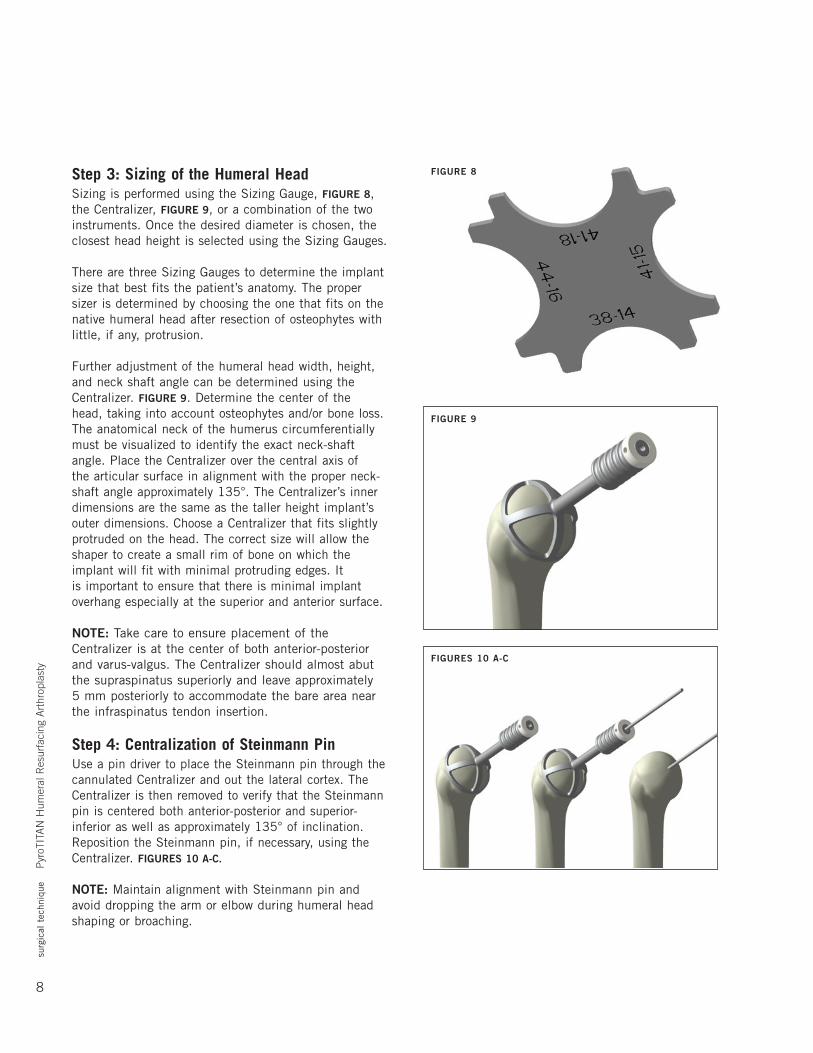
Next, the insertion of the subscapularis is released by sharp dissection 1 cm medial to the lesser tuberosity, through both tendon and capsule, or by an osteotomy of the lesser tuberosity to gain access to the glenohumeral joint. Place traction sutures in the subscapularis tendon to control and mobilize it from the anterior glenoid neck. A Darrach type retractor may be used in the glenohumeral joint to “shoe horn” or dislocate the humeral head. FIGURE 5.
NOTE: A lesser tuberosity osteotomy may be performed to take down the subscapularis if it is attenuated.
The ‘subscapularis tendon-capsule complex’ is dissected and elevated as one unit from the humerus at the medial aspect of the bicipital groove. If this complex is contracted, a 360° release of the subscapularis must be performed to mobilize the tendon to gain eventual external rotation. This is performed with a careful anterior and inferior capsular release.
The joint capsule is released primarily from the humerus. Preservation of some of the posterior capsule is maintained to facilitate centralization and prevent posterior subluxation. Take care to protect the axillary nerve as it passes inferior to the subscapularis and capsule.
At this point, the humeral head should freely rotate into maximum external rotation, slight abduction, and significant extension, allowing the head to dislocate anteriorly for preparation of the humeral head. FIGURE 6.
Full exposure of the humeral head, neck, and glenoid can now be achieved. Angled Hohmann retractors will be of great help in delivering the humeral head to the proper position, while carefully protecting the adjacent soft tissue. FIGURE 7.
NOTE: The humeral head must be anteriorly translated without soft tissue interposition.
Releasing the inferior capsule off the humerus is an essential pearl in gaining exposure, at least past the 6 o'clock position. Bone preparation is initiated by debridement of sufficient amounts of anterior inferior osteophytes to properly identify the anatomic neck.
FIGURE 5
FIGURE 6
FIGURE 7
8
surg
ical
tec
hniq
ue
Pyr
oTIT
AN
Hum
eral
Res
urfa
cing
Art
hrop
last
y
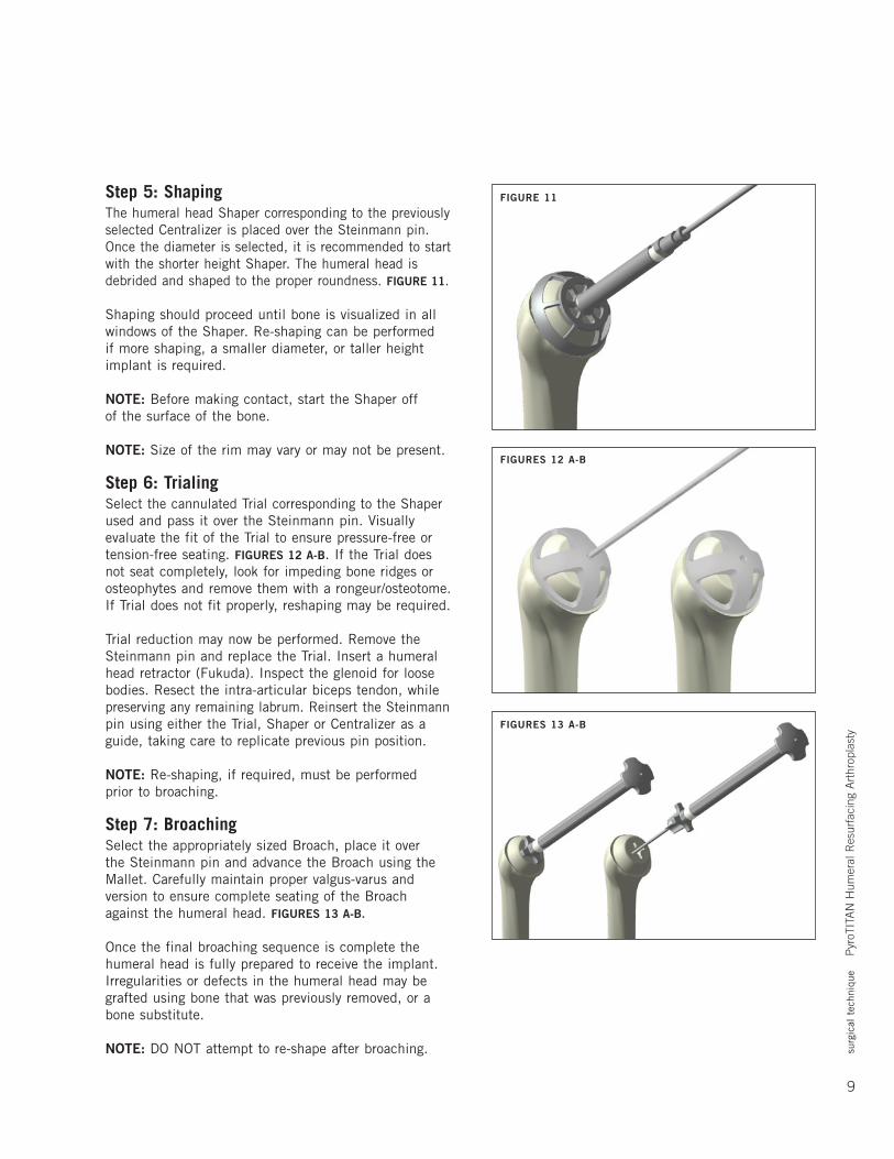
Step 3: Sizing of the Humeral HeadSizing is performed using the Sizing Gauge, FIGURE 8, the Centralizer, FIGURE 9, or a combination of the two instruments. Once the desired diameter is chosen, the closest head height is selected using the Sizing Gauges.
There are three Sizing Gauges to determine the implant size that best fits the patient’s anatomy. The proper sizer is determined by choosing the one that fits on the native humeral head after resection of osteophytes with little, if any, protrusion.
Further adjustment of the humeral head width, height, and neck shaft angle can be determined using the Centralizer. FIGURE 9. Determine the center of the head, taking into account osteophytes and/or bone loss. The anatomical neck of the humerus circumferentially must be visualized to identify the exact neck-shaft angle. Place the Centralizer over the central axis of the articular surface in alignment with the proper neck-shaft angle approximately 135°. The Centralizer’s inner dimensions are the same as the taller height implant’s outer dimensions. Choose a Centralizer that fits slightly protruded on the head. The correct size will allow the shaper to create a small rim of bone on which the implant will fit with minimal protruding edges. It is important to ensure that there is minimal implant overhang especially at the superior and anterior surface.
NOTE: Take care to ensure placement of the Centralizer is at the center of both anterior-posterior and varus-valgus. The Centralizer should almost abut the supraspinatus superiorly and leave approximately 5 mm posteriorly to accommodate the bare area near the infraspinatus tendon insertion.
Step 4: Centralization of Steinmann PinUse a pin driver to place the Steinmann pin through the cannulated Centralizer and out the lateral cortex. The Centralizer is then removed to verify that the Steinmann pin is centered both anterior-posterior and superior-inferior as well as approximately 135° of inclination. Reposition the Steinmann pin, if necessary, using the Centralizer. FIGURES 10 A-C.
NOTE: MaintainalignmentwithSteinmannpinandavoid dropping the arm or elbow during humeral head shaping or broaching.
FIGURES 10 A-C
FIGURE 9
FIGURE 8
surg
ical
tec
hniq
ue
Pyr
oTIT
AN
Hum
eral
Res
urfa
cing
Art
hrop
last
y
9
Step 5: ShapingThe humeral head Shaper corresponding to the previously selected Centralizer is placed over the Steinmann pin. Once the diameter is selected, it is recommended to start with the shorter height Shaper. The humeral head is debrided and shaped to the proper roundness. FIGURE 11.
Shaping should proceed until bone is visualized in all windows of the Shaper. Re-shaping can be performed if more shaping, a smaller diameter, or taller height implant is required.
NOTE: Before making contact, start the Shaper off of the surface of the bone.
NOTE: Size of the rim may vary or may not be present.
Step 6: TrialingSelect the cannulated Trial corresponding to the Shaper used and pass it over the Steinmann pin. Visually evaluate the fit of the Trial to ensure pressure-free or tension-free seating. FIGURES 12 A-B. If the Trial does not seat completely, look for impeding bone ridges or osteophytes and remove them with a rongeur/osteotome. If Trial does not fit properly, reshaping may be required.
Trial reduction may now be performed. Remove the Steinmann pin and replace the Trial. Insert a humeral head retractor (Fukuda). Inspect the glenoid for loose bodies. Resect the intra-articular biceps tendon, while preserving any remaining labrum. Reinsert the Steinmann pin using either the Trial, Shaper or Centralizer as a guide, taking care to replicate previous pin position.
NOTE: Re-shaping, if required, must be performed prior to broaching.
Step 7: BroachingSelect the appropriately sized Broach, place it over the Steinmann pin and advance the Broach using the Mallet.Carefullymaintainpropervalgus-varusandversion to ensure complete seating of the Broach against the humeral head. FIGURES 13 A-B.
Once the final broaching sequence is complete the humeral head is fully prepared to receive the implant. Irregularities or defects in the humeral head may be grafted using bone that was previously removed, or a bone substitute.
NOTE: DO NOT attempt to re-shape after broaching.
FIGURES 13 A-B
FIGURES 12 A-B
FIGURE 11
10
surg
ical
tec
hniq
ue
Pyr
oTIT
AN
Hum
eral
Res
urfa
cing
Art
hrop
last
y
If the subscapularis tendon-capsule is contracted, a 360° release of the subscapularis must be performed to mobilize the tendon to gain eventual external rotation. This is performed with a careful anterior and inferior capsular release.
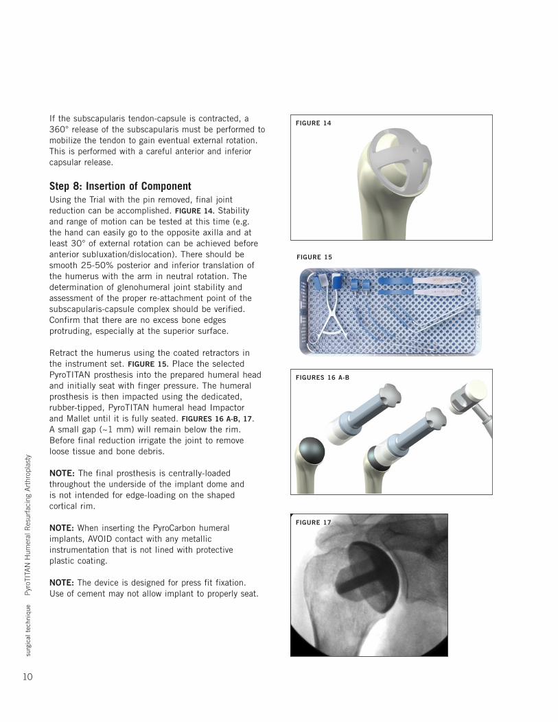
Step 8: Insertion of ComponentUsing the Trial with the pin removed, final joint reduction can be accomplished. FIGURE 14. Stability and range of motion can be tested at this time (e.g. the hand can easily go to the opposite axilla and at least 30° of external rotation can be achieved before anterior subluxation/dislocation). There should be smooth 25-50% posterior and inferior translation of the humerus with the arm in neutral rotation. The determination of glenohumeral joint stability and assessment of the proper re-attachment point of the subscapularis-capsule complex should be verified. Confirm that there are no excess bone edges protruding, especially at the superior surface.
Retract the humerus using the coated retractors in the instrument set. FIGURE 15. Place the selected PyroTITAN prosthesis into the prepared humeral head and initially seat with finger pressure. The humeral prosthesis is then impacted using the dedicated, rubber-tipped, PyroTITAN humeral head Impactor andMalletuntilitisfullyseated.FIGURES 16 A-B, 17. A small gap (~1 mm) will remain below the rim. Before final reduction irrigate the joint to remove loose tissue and bone debris.
NOTE: The final prosthesis is centrally-loaded throughout the underside of the implant dome and is not intended for edge-loading on the shaped cortical rim.
NOTE: When inserting the PyroCarbon humeral implants, AVOID contact with any metallic instrumentation that is not lined with protective plastic coating.
NOTE: The device is designed for press fit fixation. Use of cement may not allow implant to properly seat.
FIGURE 14
FIGURE 15
FIGURES 16 A-B
FIGURE 17
surg
ical
tec
hniq
ue
Pyr
oTIT
AN
Hum
eral
Res
urfa
cing
Art
hrop
last
y
11
Extraction of the ImplantIndications for revision may include infection, glenoid wear, implant loosening or dislocation. Additionally, in rare cases, removal of the implant may be required during revision surgery. Attain exposure as described previously.
Attach the extractor to the implant that is to be removed. This may require removal of a small amount of bone at the edge of the implant to allow the tips of the extractor to be attached to the edge of the implant. Extract the implant by impacting the underside of the extractor strike plate using the slotted mallet. Retighten the extractor onto the implant as it is backed out of the humerus to ensure the implant is secured onto the extractor. If the implant is well-fixed and cannot be easily extracted, a saw can be used to cut the periphery of the humerus at the bone-implant junction. The implant and the contained humeral bone can then be removed together. The surface of the remaining humerus can then be prepared for conversion to a stemmed humeral component.
NOTE: To prevent accidental scoring and/or damage to the PyroCarbon implant, assure that all edges of the extractor are fully secured under the edge of the implant before extraction attempts.
NOTE: For instances of a well-fixed implant, avoid direct contact of the saw to the implant. Only cut the cortical bone near the peripheral edges of the humeral head.
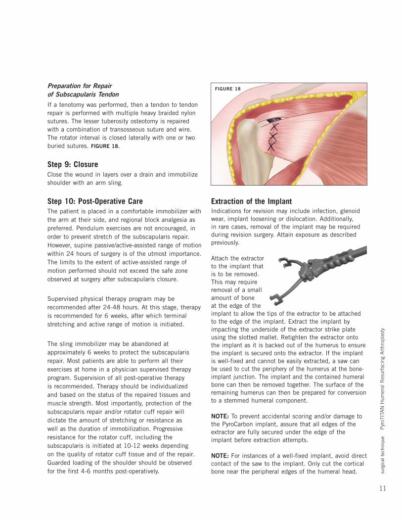
Preparation for Repair of Subscapularis TendonIf a tenotomy was performed, then a tendon to tendon repair is performed with multiple heavy braided nylon sutures. The lesser tuberosity osteotomy is repaired with a combination of transosseous suture and wire. The rotator interval is closed laterally with one or two buried sutures. FIGURE 18.
Step 9: ClosureClose the wound in layers over a drain and immobilize shoulder with an arm sling.
Step 10: Post-Operative CareThe patient is placed in a comfortable immobilizer with the arm at their side, and regional block analgesia as preferred. Pendulum exercises are not encouraged, in order to prevent stretch of the subscapularis repair. However, supine passive/active-assisted range of motion within 24 hours of surgery is of the utmost importance. The limits to the extent of active-assisted range of motion performed should not exceed the safe zone observed at surgery after subscapularis closure.
Supervised physical therapy program may be recommended after 24-48 hours. At this stage, therapy is recommended for 6 weeks, after which terminal stretching and active range of motion is initiated.
The sling immobilizer may be abandoned at approximately 6 weeks to protect the subscapularis repair.Mostpatientsareabletoperformalltheirexercises at home in a physician supervised therapy program. Supervision of all post-operative therapy is recommended. Therapy should be individualized and based on the status of the repaired tissues and musclestrength.Mostimportantly,protectionofthesubscapularis repair and/or rotator cuff repair will dictate the amount of stretching or resistance as well as the duration of immobilization. Progressive resistance for the rotator cuff, including the subscapularis is initiated at 10-12 weeks depending on the quality of rotator cuff tissue and of the repair. Guarded loading of the shoulder should be observed for the first 4-6 months post-operatively.
FIGURE 18
12
surg
ical
tec
hniq
ue
Pyr
oTIT
AN
Hum
eral
Res
urfa
cing
Art
hrop
last
y
iteM/deSCRiPtiOn CataLOgnuMbeR
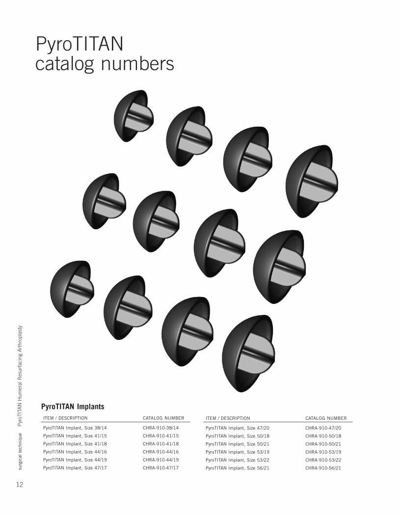
PyroTITAN Implant, Size 47/20 CHRA-910-47/20
PyroTITAN Implant, Size 50/18 CHRA-910-50/18
PyroTITAN Implant, Size 50/21 CHRA-910-50/21
PyroTITAN Implant, Size 53/19 CHRA-910-53/19
PyroTITAN Implant, Size 53/22 CHRA-910-53/22
PyroTITAN Implant, Size 56/21 CHRA-910-56/21
PyroTITANcatalog numbers
PyroTITAN Implants iteM/deSCRiPtiOn CataLOgnuMbeR
PyroTITAN Implant, Size 38/14 CHRA-910-38/14
PyroTITAN Implant, Size 41/15 CHRA-910-41/15
PyroTITAN Implant, Size 41/18 CHRA-910-41/18
PyroTITAN Implant, Size 44/16 CHRA-910-44/16
PyroTITAN Implant, Size 44/19 CHRA-910-44/19
PyroTITAN Implant, Size 47/17 CHRA-910-47/17
surg
ical
tec
hniq
ue
Pyr
oTIT
AN
Hum
eral
Res
urfa
cing
Art
hrop
last
y
13
iteM/deSCRiPtiOn CataLOgnuMbeR
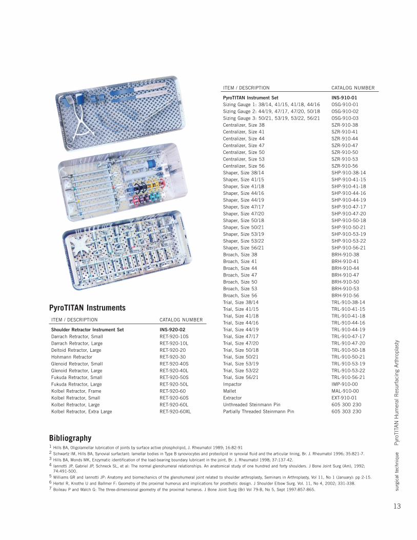
PyroTITAN Instrument Set INS-910-01 Sizing Gauge 1: 38/14, 41/15, 41/18, 44/16 OSG-910-01 Sizing Gauge 2: 44/19, 47/17, 47/20, 50/18 OSG-910-02 Sizing Gauge 3: 50/21, 53/19, 53/22, 56/21 OSG-910-03 Centralizer, Size 38 SZR-910-38 Centralizer, Size 41 SZR-910-41 Centralizer, Size 44 SZR-910-44 Centralizer, Size 47 SZR-910-47 Centralizer, Size 50 SZR-910-50 Centralizer, Size 53 SZR-910-53 Centralizer, Size 56 SZR-910-56 Shaper, Size 38/14 SHP-910-38-14 Shaper, Size 41/15 SHP-910-41-15 Shaper, Size 41/18 SHP-910-41-18 Shaper, Size 44/16 SHP-910-44-16 Shaper, Size 44/19 SHP-910-44-19 Shaper, Size 47/17 SHP-910-47-17 Shaper, Size 47/20 SHP-910-47-20 Shaper, Size 50/18 SHP-910-50-18 Shaper, Size 50/21 SHP-910-50-21 Shaper, Size 53/19 SHP-910-53-19 Shaper, Size 53/22 SHP-910-53-22 Shaper, Size 56/21 SHP-910-56-21 Broach, Size 38 BRH-910-38 Broach, Size 41 BRH-910-41 Broach, Size 44 BRH-910-44 Broach, Size 47 BRH-910-47 Broach, Size 50 BRH-910-50 Broach, Size 53 BRH-910-53 Broach, Size 56 BRH-910-56trial,Size38/14 tRL-910-38-14trial,Size41/15 tRL-910-41-15trial,Size41/18 tRL-910-41-18trial,Size44/16 tRL-910-44-16trial,Size44/19 tRL-910-44-19trial,Size47/17 tRL-910-47-17trial,Size47/20 tRL-910-47-20trial,Size50/18 tRL-910-50-18trial,Size50/21 tRL-910-50-21trial,Size53/19 tRL-910-53-19trial,Size53/22 tRL-910-53-22trial,Size56/21 tRL-910-56-21 impactor iMP-910-00Mallet MaL-910-00 Extractor EXT-910-01 Unthreaded Steinmann Pin 605 300 230 Partially Threaded Steinmann Pin 605 303 230
PyroTITAN Instruments iteM/deSCRiPtiOn CataLOgnuMbeR
Shoulder Retractor Instrument Set INS-920-02 Darrach Retractor, Small RET-920-10SdarrachRetractor,Large Ret-920-10LdeltoidRetractor,Large Ret-920-20 Hohmann Retractor RET-920-30 Glenoid Retractor, Small RET-920-40SglenoidRetractor,Large Ret-920-40L Fukuda Retractor, Small RET-920-50SFukudaRetractor,Large Ret-920-50L Kolbel Retractor, Frame RET-920-60 Kolbel Retractor, Small RET-920-60SKolbelRetractor,Large Ret-920-60LKolbelRetractor,extraLarge Ret-920-60XL
Bibliography1 Hills BA, Oligolamellar lubrication of joints by surface active phospholipid, J. Rheumatol 1989; 16:82-912 SchwartziM,Hillsba,Synovialsurfactant:lamellarbodiesintypebsynoviocytesandproteolipidinsynovialfluidandthearticularlining,br.J.Rheumatol1996;35:821-7.3 Hillsba,MondsMK,enzymaticidentificationoftheload-bearingboundarylubricantinthejoint,br.J.Rheumatol1998;37:137-42.4 iannottiJP,gabrielJP,SchneckSL,etal:thenormalglenohumeralrelationships.ananatomicalstudyofonehundredandfortyshoulders.JboneJointSurg(am),1992;
74:491-500.5 Williams GR and Iannotti JP: Anatomy and biomechanics of the glenohumeral joint related to shoulder arthroplasty, Seminars in Arthroplasty, Vol 11, No 1 (January): pp 2-15.6 Hertel R, Knothe U and Ballmer F: Geometry of the proximal humerus and implications for prosthetic design. J Shoulder Elbow Surg. Vol. 11, No 4, 2002; 331-338.7 Boileau P and Walch G: The three-dimensional geometry of the proximal humerus. J Bone Joint Surg (Br) Vol 79-B, No 5, Sept 1997:857-865.

At Ascension Orthopedics, we are dedicated to transforming the surgical experience.
Ascension Orthopedics, Inc.8700 Cameron RoadAustin, Texas 78754
512.836.5001 Ph 877.370.5001 TFP 512.836.6933 Fax 888.508.8081 TFF
Transforming Extremities™
Additional upper extremity solutions:
Ascension®
CoCr TITAN™ HumeralResurfacing
Ascension® Radial Head Fixation System
First Choice® DRUJ System
Ascension® PyroCarbon CMC Arthroplasty
Ascension® MCP/PIP PyroCarbon Total Joints
Ascension® MCP/PIP Silicone Joints
Caution: U.S. federal law restricts this device to sale by or on the order of a physician.
LC-04-917-001 rev B©2010


![Humeral Resurfacing Head - University of Washingtonfaculty.washington.edu/alexbert/Shoulder/Surgery/...head [ Fig. 12 ] and through to the lateral cortex to provide stability. The](https://img.pdfslide.net/doc/110x75/60a585dbb9021c2b170943fa/humeral-resurfacing-head-university-of-head-fig-12-and-through-to-the.jpg)