Embed Size (px)
Citation preview
QoS for WiMAX Mesh
Minor Project Report
Eshan Nanda
2010MCS3489
Under the Guidance of
Dr. Vinay Joseph Ribeiro
Department of Computer Science & Engineering
Indian Institute of Technology Delhi
1
Abstract
This project aims at providing Quality of Service (Qos) for a WiMAX(IEEE 802.16
standard) based relay network which is currently implemented on WARP (Wireless Open
Access Research Platform) boards. With the help of priority based queues, data will be
handled on the basis of its corresponding priority. Basically TCP and UDP classes of
data has been considered and di�erentiated services for those classes have been provided.
Thus the network are expected to provide much better quality of service than the already
built network (which have no provision for QoS reservations). Di�erentiated services on
the basis of the subscriber station have also been implemented. The implementation
testbed WARP from Rice university is a FPGA based software radio which provides a
scalable and congurable platform for prototyping wireless communication algorithms. Its
programmability and exibility makes it easy to implement various physical and network
layer protocols and standards.
2
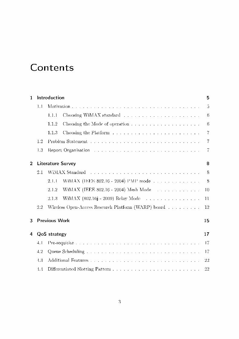
Contents
1 Introduction 5
1.1 Motivation . . . . . . . . . . . . . . . . . . . . . . . . . . . . . . . . . . . 5
1.1.1 Choosing WiMAX standard . . . . . . . . . . . . . . . . . . . . . 6
1.1.2 Choosing the Mode of operation . . . . . . . . . . . . . . . . . . . 6
1.1.3 Choosing the Platform . . . . . . . . . . . . . . . . . . . . . . . . 7
1.2 Problem Statement . . . . . . . . . . . . . . . . . . . . . . . . . . . . . . 7
1.3 Report Organisation . . . . . . . . . . . . . . . . . . . . . . . . . . . . . 7
2 Literature Survey 8
2.1 WiMAX Standard . . . . . . . . . . . . . . . . . . . . . . . . . . . . . . 8
2.1.1 WiMAX (IEEE 802.16 - 2004) PMP mode . . . . . . . . . . . . . 8
2.1.2 WiMAX (IEEE 802.16 - 2004) Mesh Mode . . . . . . . . . . . . 10
2.1.3 WiMAX (802.16j - 2009) Relay Mode . . . . . . . . . . . . . . . 11
2.2 Wireless Open-Access Research Platform (WARP) board . . . . . . . . . 12
3 Previous Work 15
4 QoS strategy 17
4.1 Pre-requisite . . . . . . . . . . . . . . . . . . . . . . . . . . . . . . . . . . 17
4.2 Queue Scheduling . . . . . . . . . . . . . . . . . . . . . . . . . . . . . . . 17
4.3 Additional Features . . . . . . . . . . . . . . . . . . . . . . . . . . . . . . 22
4.4 Di�erentiated Slotting Pattern . . . . . . . . . . . . . . . . . . . . . . . . 22
3
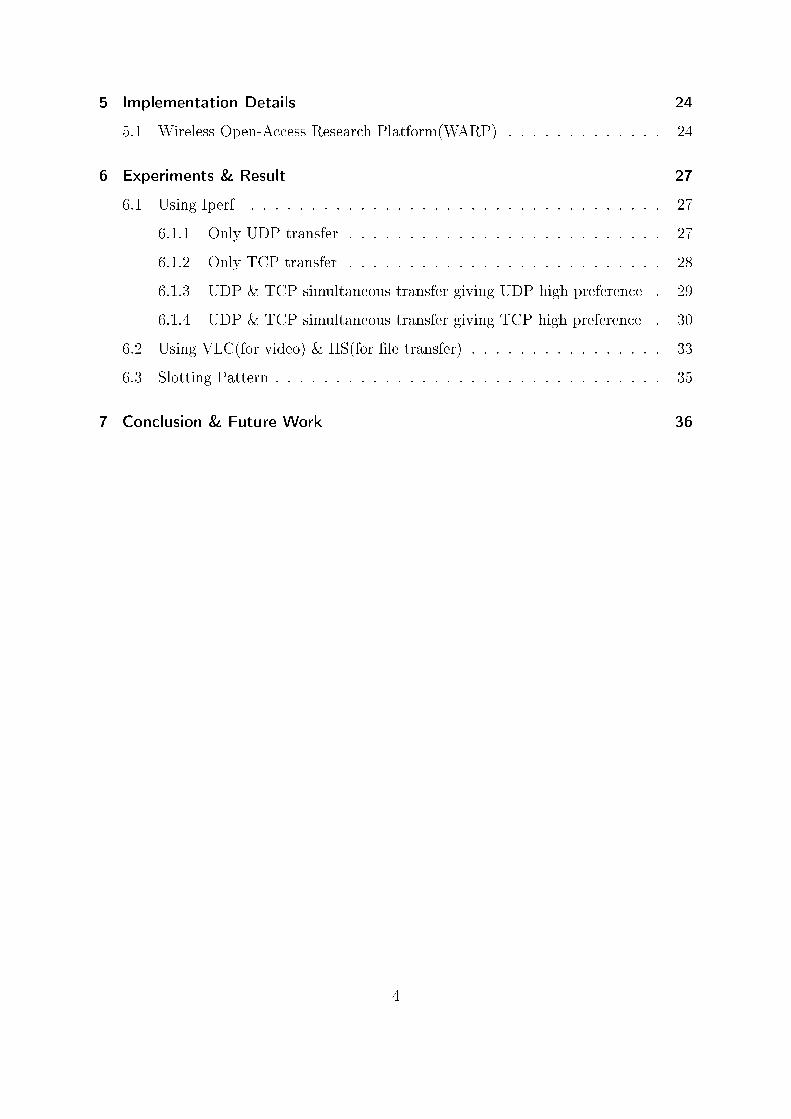
5 Implementation Details 24
5.1 Wireless Open-Access Research Platform(WARP) . . . . . . . . . . . . . 24
6 Experiments & Result 27
6.1 Using Iperf . . . . . . . . . . . . . . . . . . . . . . . . . . . . . . . . . . 27
6.1.1 Only UDP transfer . . . . . . . . . . . . . . . . . . . . . . . . . . 27
6.1.2 Only TCP transfer . . . . . . . . . . . . . . . . . . . . . . . . . . 28
6.1.3 UDP & TCP simultaneous transfer giving UDP high preference . 29
6.1.4 UDP & TCP simultaneous transfer giving TCP high preference . 30
6.2 Using VLC(for video) & IIS(for �le transfer) . . . . . . . . . . . . . . . . 33
6.3 Slotting Pattern . . . . . . . . . . . . . . . . . . . . . . . . . . . . . . . . 35
7 Conclusion & Future Work 36
4
1 Introduction
WiMAX, means "Worldwide Interoperability for Microwave Access" and is a telecommu-
nications technology that provides wireless transmission of data using a variety of trans-
mission modes. It is based on the IEEE 802.16 standard (also called Broadband Wireless
Access). The WiMAX standard species three modes of operation: a point-to-multipoint
(PMP) mode a, a MeSH mode and relay mode of operation. A wireless mesh network
is basically a multihop ad hoc network where each node behaves as a router. Mesh
networks have two kinds of nodes: mesh routers and mesh clients. Mesh routers are
usually non mobile and both conventional and mesh clients can connect to them. Both
mesh clients and mesh routers can act as routers. Also, there are mesh portal points
which connect the mesh network to the outside world, for example, the Internet. Thus
the network possesses self organizing, self healing and self conguring capabilities. This
provides robustness, reliability and ease of maintenance to wireless mesh networks. The
network built previously didnt have any facility for providing di�erentiated services.
Thus to provide priority based transmission of important data QoS is required.
1.1 Motivation
The need of an hour is to provide a self-con�gurable, rapid deployable and robust network
to be made available in case of an emergency or warfare when the currently existing
infrastructure becomes unmanageable or damaged.
5
1.1.1 Choosing WiMAX standard
It is often impossible to access remote databases, use web-based applications, and com-
municate with headquarters and other command centres by making use of video confer-
encing and other collaborative tools in case of an emergency situation. The communi-
cation plays a very important role in saving crucial lives in those situation. So, in such
scenarios there is a need of communication infrastructure that is rapidly deployable,
self-con�gurable and provides high performance in terms of throughput and latency to
enable triple-play (voice, video, and data) applications. Such a network can be best de-
ployed as Multi-Hop WiMAX based network owing to its longer range (few Kms), QoS
provisions in the standard and state-of the art technologies (MIMO, OFDM). WiMAX
satisfy all those requirements from every aspect.
1.1.2 Choosing the Mode of operation
• Point to Multipoint (PMP) mode : In this several Subscriber station(SS) are
connected to a central Base station(BS). All SS are within one hop of the BS hence
the size of the network possible is restricted
• Mesh mode : It is a topology for subscriber-to-subscriber communication in
non-line of sight conditions. This mode allows the network to operate even if an
SS is not within direct range of the BS. The frame structure of this mode is not
compatible with the PMP mode.
• Relay mode : It is used to provide coverage extension and throughput enhance-
ment by introducing the Relay stations(RS) in an access network. It is based on
a tree structure. The RS, thus, relays tra�c between the SS and MR-BS(which is
the main Base Station) extending the coverage and performance of the system in
areas where RSs are deployed. The frame structure is PMP compatible. So, the
legacy 802.16 subscriber stations are able to communicate with the Relay stations.
The network being built use this mode of operation. Other advantages of the relay
6
approach are a less complex design and construction than typical base stations,
lower total system cost, and enabling rapid deployment
1.1.3 Choosing the Platform
Wireless Open-Access Research Platform (WARP) designed and developed at Rice Uni-
versity, USA is a scalable and extensible programmable wireless platform, built from the
ground up, to prototype advanced wireless networks. It has been designed for prototyp-
ing and implementing physical layer, MAC layer protocols thus providing a cross layer
development platform.
1.2 Problem Statement
The projects aims to provide the Quality of service (QoS) to the WiMAX (IEEE 802.16
standard) based relay network which is already being implemented on WARP (Wireless
Open Access Research Platform) boards by WiMAX group.
1.3 Report Organisation
• Chapter 2 describes Background reading (WiMAX technology and its modes,
WARP understanding)
• Chapter 3 describes the previous work done on WiMAX project
• Chapter 4 describes the strategy used for providing QoS
• Chapter 5 describes the implementation platform
• Chapter 6 describes the experiment and result obtained
• Chapter 7 gives the conclusion
7
2 Literature Survey
This chapter summarised the knowledge gained from reading material available.
2.1 WiMAX Standard
The IEEE 802.16 Wireless MAN standard which has emerged as Broad-band Wireless
Access (BWA) solution is quite promising to meet the requirements of highbandwidth
and realtime application. WiMAX is based on wireless metropolitan area networking
(WMAN) standards developed by the IEEE 802.16 group and is widely adopted by
IEEE. There are three di�erent modes in which WiMAX can operate which will be
explained one by one in the following section
2.1.1 WiMAX (IEEE 802.16 - 2004) PMP mode
In this mode all subscriber stations (SS) are within one hop from the base station (BS).
In this various user share the channel using Time Division Multiplexing Access (TDMA).
The BS controls the scheduling by alloting slots to a subscriber station. In this mode all
SS are required to be present within one hop distance from the BS as all communication
occurs through the base station.
The Frame structure has a Downlink (DL) subframe and an uplink(UL) subframe
with the DL subframe always preceding the UL subframe. The DL subframe is made
up of a preamble, Frame Control Header (FCH), and a number of data bursts.
8
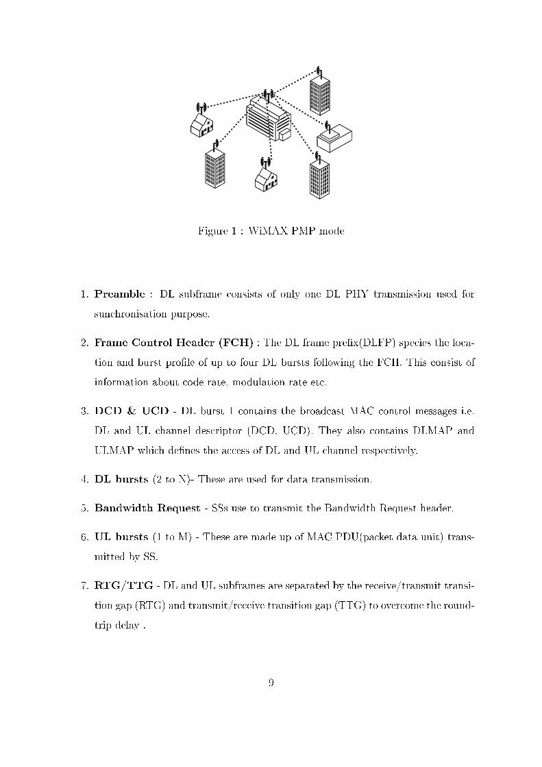
Figure 1 : WiMAX PMP mode
1. Preamble : DL subframe consists of only one DL PHY transmission used for
sunchronisation purpose.
2. Frame Control Header (FCH) : The DL frame pre�x(DLFP) species the loca-
tion and burst pro�le of up to four DL bursts following the FCH. This consist of
information about code rate, modulation rate etc.
3. DCD & UCD - DL burst 1 contains the broadcast MAC control messages i.e.
DL and UL channel descriptor (DCD, UCD). They also contains DLMAP and
ULMAP which de�nes the access of DL and UL channel respectively.
4. DL bursts (2 to N)- These are used for data transmission.
5. Bandwidth Request - SSs use to transmit the Bandwidth Request header.
6. UL bursts (1 to M) - These are made up of MAC PDU(packet data unit) trans-
mitted by SS.
7. RTG/TTG - DL and UL subframes are separated by the receive/transmit transi-
tion gap (RTG) and transmit/receive transition gap (TTG) to overcome the round-
trip delay .
9
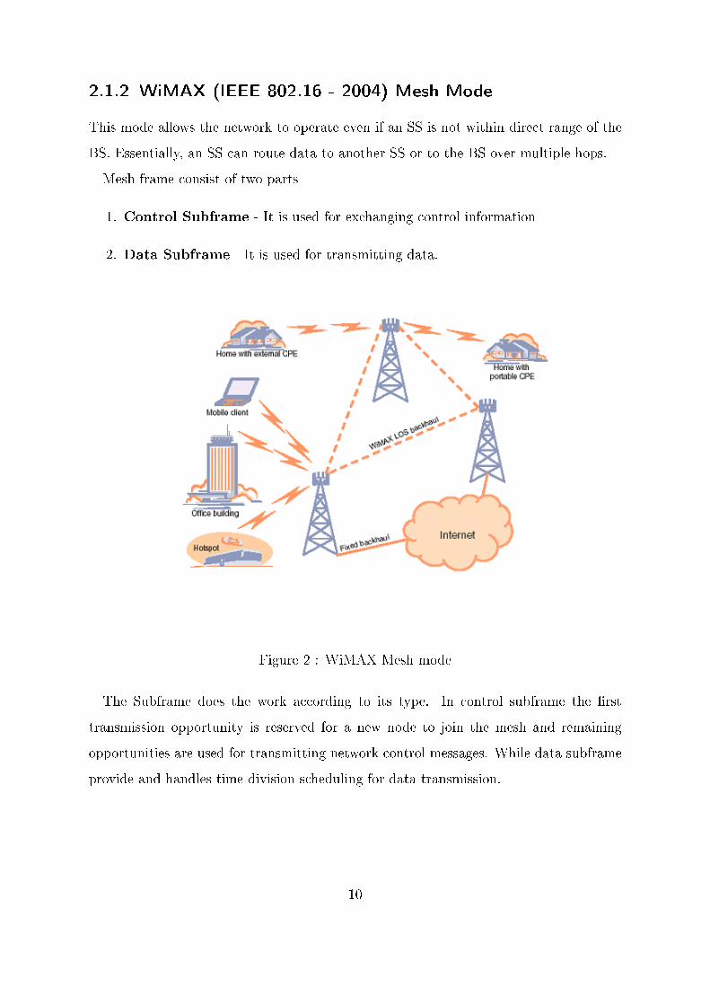
2.1.2 WiMAX (IEEE 802.16 - 2004) Mesh Mode
This mode allows the network to operate even if an SS is not within direct range of the
BS. Essentially, an SS can route data to another SS or to the BS over multiple hops.
Mesh frame consist of two parts
1. Control Subframe - It is used for exchanging control information
2. Data Subframe - It is used for transmitting data.
Figure 2 : WiMAX Mesh mode
The Subframe does the work according to its type. In control subframe the �rst
transmission opportunity is reserved for a new node to join the mesh and remaining
opportunities are used for transmitting network control messages. While data subframe
provide and handles time division scheduling for data transmission.
10
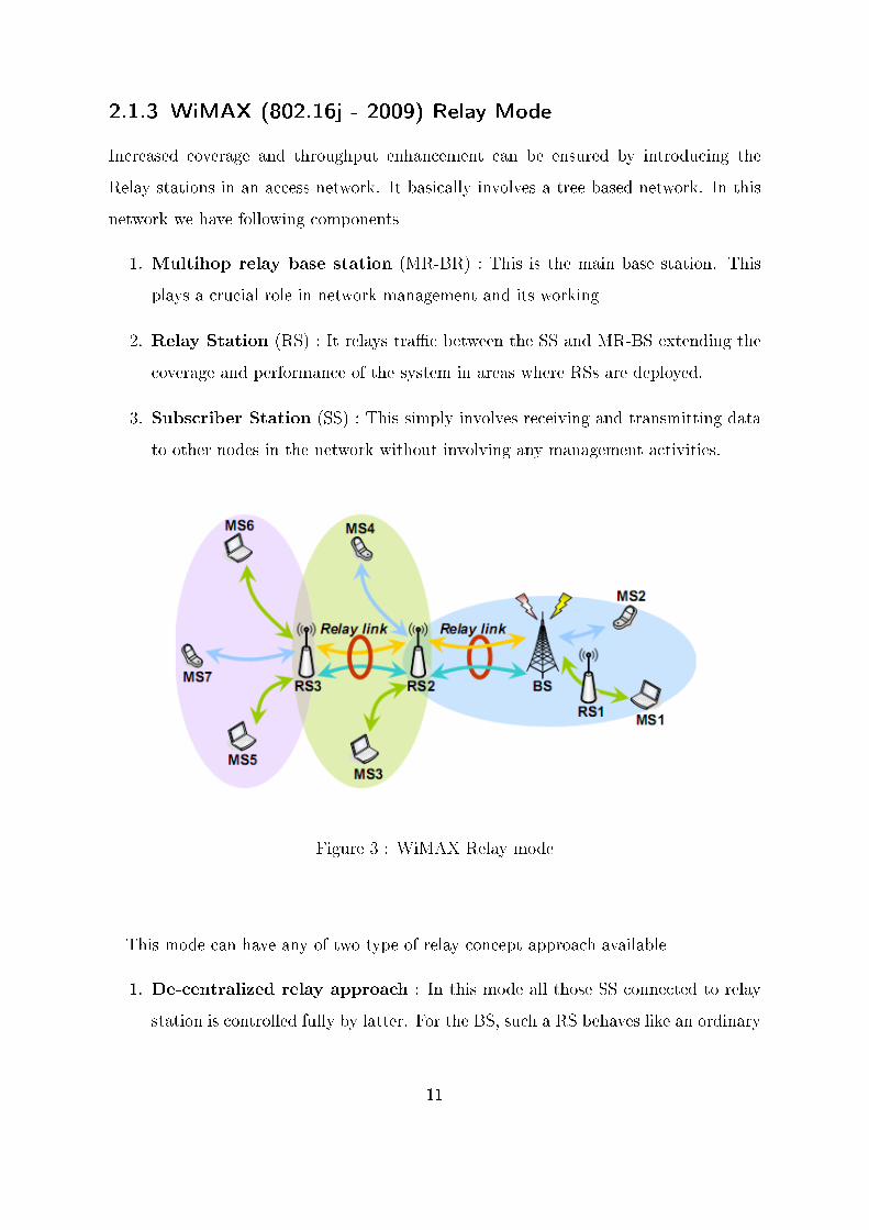
2.1.3 WiMAX (802.16j - 2009) Relay Mode
Increased coverage and throughput enhancement can be ensured by introducing the
Relay stations in an access network. It basically involves a tree based network. In this
network we have following components
1. Multihop relay base station (MR-BR) : This is the main base station. This
plays a crucial role in network management and its working
2. Relay Station (RS) : It relays tra�c between the SS and MR-BS extending the
coverage and performance of the system in areas where RSs are deployed.
3. Subscriber Station (SS) : This simply involves receiving and transmitting data
to other nodes in the network without involving any management activities.
Figure 3 : WiMAX Relay mode
This mode can have any of two type of relay concept approach available
1. De-centralized relay approach : In this mode all those SS connected to relay
station is controlled fully by latter. For the BS, such a RS behaves like an ordinary
11
SS. For other SSs at the same level, this relay appears like an ordinary SS. For SSs
which are subscribed to this relay it appears to be a regular BS.
2. Centralized relay approach : In this mode the BS completely controls all the
nodes in the network even those nodes connected directly to RS.
The network being implemented uses a centralised approach as they involve greater
control in terms of priorities and QoS. TDMA based approach is used in network as
they have been proved to be deterministic.
2.2 Wireless Open-Access Research Platform
(WARP) board
Extensive tutorials are available on the WARP Rice University website[2] which gives
large amount of detail for gaining knowledge of the platform. Development of MAC
layer for WARP board can be done. The knowledge of OFDM reference design can be
better understood by executing the CSMA code available.
CSMA MAC working has been described using the following state diagram which
completely describe its working.
12
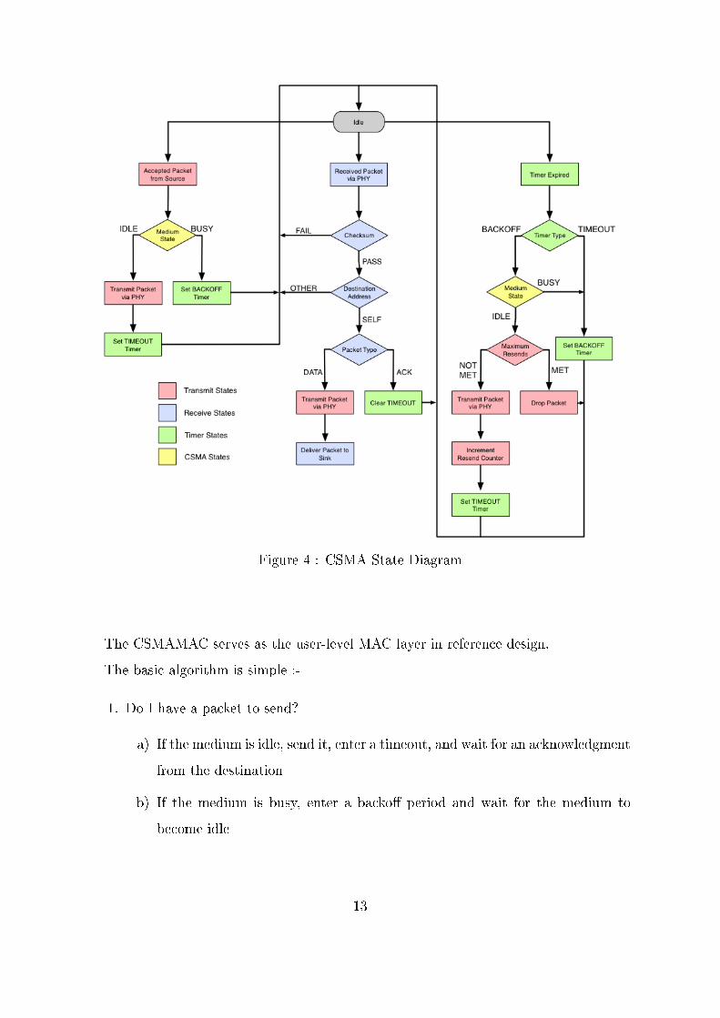
Figure 4 : CSMA State Diagram
The CSMAMAC serves as the user-level MAC layer in reference design.
The basic algorithm is simple :-
1. Do I have a packet to send?
a) If the medium is idle, send it, enter a timeout, and wait for an acknowledgment
from the destination
b) If the medium is busy, enter a backo� period and wait for the medium to
become idle
13

2. Did I receive a data packet?
a) If the packet pass checksum and is addressed to me, send an acknowledgment
3. Did no know acknowledgment happen during a timeout period?
a) If the maximum number of retransmits has not occurred, enter a backo� and
try retransmitting
b) If the maximum number of retransmits has occurred, drop the packet
4. Did I wait through a backo� period?
a) If the medium is busy, retransmit, increment the total number of resends,
enter a timeout, and wait for an acknowledgment from the destination
b) If the medium is busy, enter a backo� period and wait for the medium to
become idle
14
3 Previous Work
The next step after getting the feel of WARP board was getting acquainted with the
code already being developed. These involve reading of MTP reports of WiMAX group
students[3, 4]. The reports desrcibe in detail the state diagram of various components
of the WiMAX ie BS, SS and RS.
The following have been described in the reports
1. Design of the Frame structure
2. Developement of TDMA based slotting pattern
3. Implementation of multihop communication using RS
4. Frequency �ipping by RS
5. Network Entry protocol which de�ned the entry of the new node into the network
6. Improve E�ciency by polling in a de�ned manner
7. Extensive testing on four nodes available
8. Various experiments with guard intervals, bandwidths and modulation schemes
were also performed
The network topology already implemented can be better understand from the following
visualisation
15
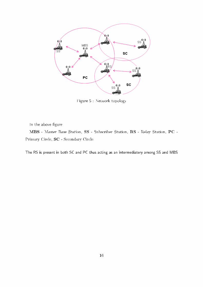
Figure 5 : Network topology
In the above �gure
MBS - Master Base Station, SS - Subscriber Station, RS - Relay Station, PC -
Primary Circle, SC - Secondary Circle
The RS is present in both SC and PC thus acting as an intermediatery among SS and MBS
16
4 QoS strategy
In this chapter, details of our QoS strategy will be discussed
4.1 Pre-requisite
1. Understanding of iperf command and its manipulation to test the Strategy em-
ployed
2. Setting and extraction of TOS or protocol bits from the IP header using various
WARP mac functions
3. Understanding of the transmitter bu�er functionality
4. Knowledge of packet transmission path through the MAC and PHY layer
4.2 Queue Scheduling
Di�erentiated services facility has not been developed for the WiMAX network, so the re-
quirement of the QoS is very essential for such a network which should handle voice,video
and data.
The steps implemented are :-
1. A Queue for a particular protocol is created eg two queues are created, one for
storing
2. Extract the Protocol/Type of Service(TOS) value from the IP header
17
3. The value can be
a) 6 - Representing TCP data, so it is transferred to TCP queue
b) 17 - Representing UDP data, so it is trans�ered to UDP queue
4. The High priority data type can be set dynamically by the user but by default
UDP have been given high preference among TCP and UDP
5. Checking of the high priority queue is done
6. If high priority queue is not empty then data packets are transmitted from it
7. Else data from the other queue is transmitted
8. The transmission depends on
a) If strict queueing strategy is employed, then data from high priority data
queue is transmitted unless it is empty. Then we move on to the next queue
b) If weighted queueing strategy is used, then some 3x number of packets are
transferred from the high priority queue, then x number of packets are trans-
ferred from the less priority queue. Then we move back to �rst queue.
Number of queues implemented for di�erent components are
1. Base station : Queues for transmission to every other node connected
2. Relay Station : Queues for every SS which is connected to it.
3. Subscriber Station : One Queue for outgoing packets
Queue represented in the above points refer to di�erent queues for di�erent data type.
The following Strategy for transmitted data from queues have been tried
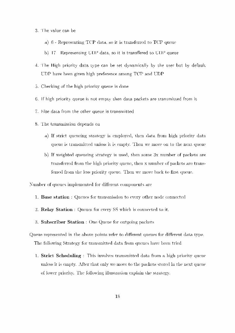
1. Strict Scheduling : This involves transmitted data from a high priority queue
unless it is empty. After that only we move to the packets stored in the next queue
of lower priority. The following illustration explain the strategy.
18
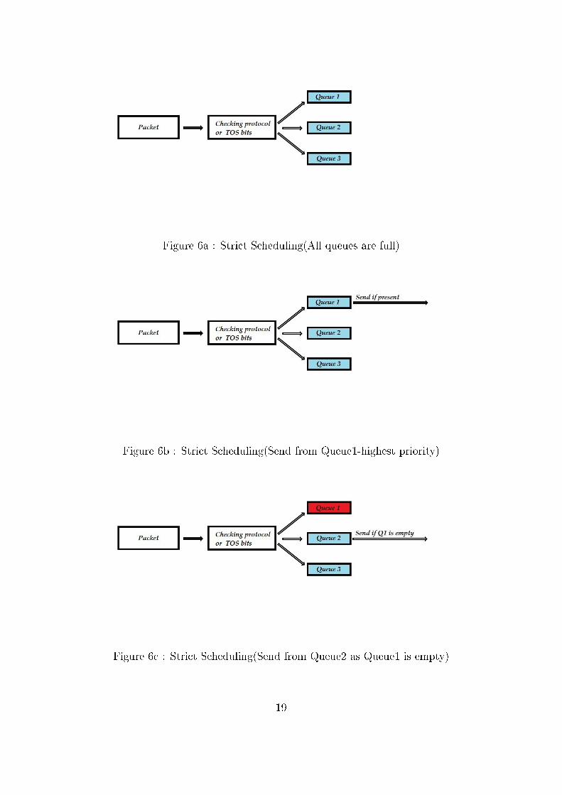
Figure 6a : Strict Scheduling(All queues are full)
Figure 6b : Strict Scheduling(Send from Queue1-highest priority)
Figure 6c : Strict Scheduling(Send from Queue2 as Queue1 is empty)
19
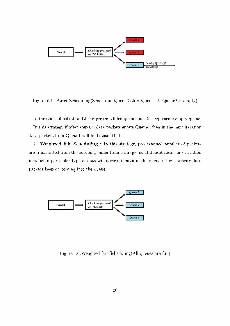
Figure 6d : Strict Scheduling(Send from Queue3 after Queue1 & Queue2 is empty)
In the above illustration Blue represents �lled queue and Red represents empty queue.
In this strategy if after step 6c, data packets enters Queue1 then in the next iteration
data packets from Queue1 will be transmitted.
2. Weighted fair Scheduling : In this strategy, predermined number of packets
are transmitted from the outgoing bu�er from each queue. It doesnt result in starvation
in which a particular type of data will always remain in the queue if high priority data
packets keep on coming into the queue.
Figure 7a :Weighted fair Scheduling(All queues are full)
20
Figure 7b : Weighted fair Scheduling(Send say 3x number of packets from
Queue1-highest priority)
Figure 7c : Weighted fair Scheduling(Send 2x packets from Queue2 )
Figure 7d : Weighted fair Scheduling(Send x packets from Queue3)
21
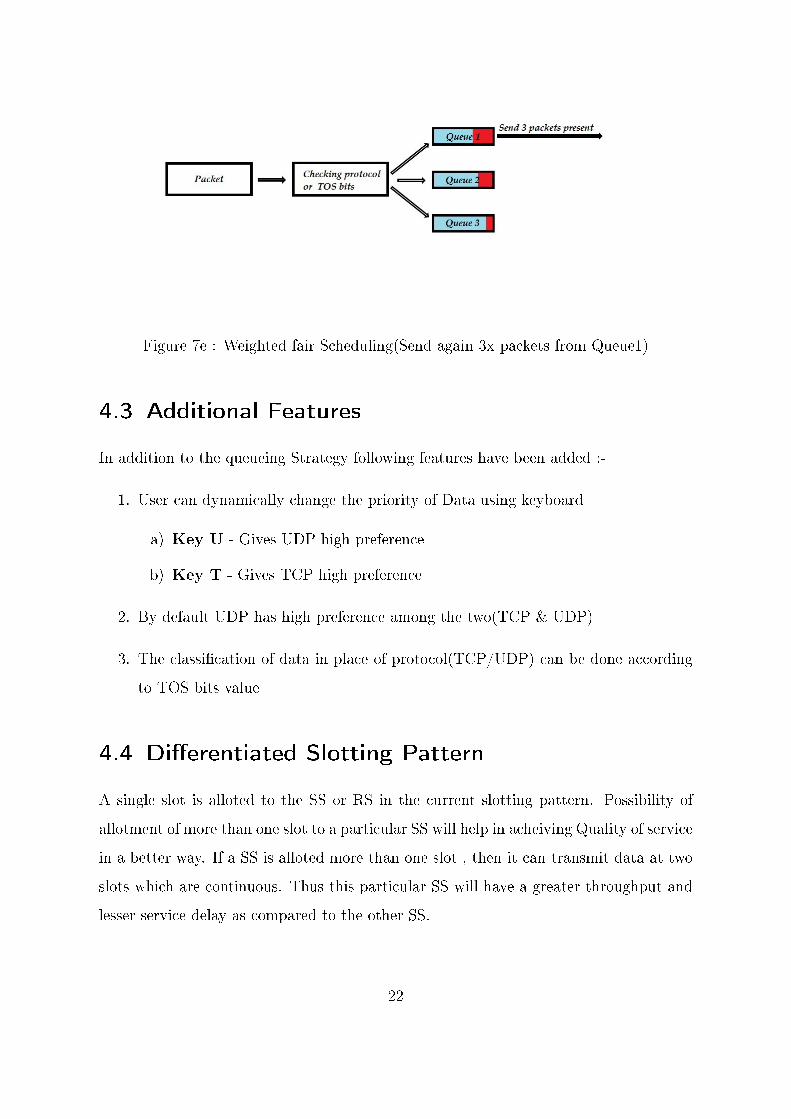
Figure 7e : Weighted fair Scheduling(Send again 3x packets from Queue1)
4.3 Additional Features
In addition to the queueing Strategy following features have been added :-
1. User can dynamically change the priority of Data using keyboard
a) Key U - Gives UDP high preference
b) Key T - Gives TCP high preference
2. By default UDP has high preference among the two(TCP & UDP)
3. The classi�cation of data in place of protocol(TCP/UDP) can be done according
to TOS bits value
4.4 Di�erentiated Slotting Pattern
A single slot is alloted to the SS or RS in the current slotting pattern. Possibility of
allotment of more than one slot to a particular SS will help in acheiving Quality of service
in a better way. If a SS is alloted more than one slot , then it can transmit data at two
slots which are continuous. Thus this particular SS will have a greater throughput and
lesser service delay as compared to the other SS.
22

The current slotting pattern implemented is static, that is we are beforehand deciding
which SS will enjoy this facility. This involves hardcoding the SS id in the code. Further
to this, a dynamic approach for di�erentiated slot allotment can be implemented.
23
5 Implementation Details
This chapter covers the Implementation Platform ie WARP boards in detail
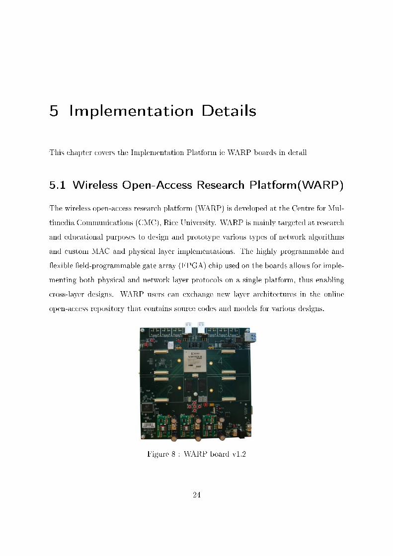
5.1 Wireless Open-Access Research Platform(WARP)
The wireless open-access research platform (WARP) is developed at the Centre for Mul-
timedia Communications (CMC), Rice University. WARP is mainly targeted at research
and educational purposes to design and prototype various types of network algorithms
and custom MAC and physical layer implementations. The highly programmable and
�exible �eld-programmable gate array (FPGA) chip used on the boards allows for imple-
menting both physical and network layer protocols on a single platform, thus enabling
cross-layer designs. WARP users can exchange new layer architectures in the online
open-access repository that contains source codes and models for various designs.
Figure 8 : WARP board v1.2
24
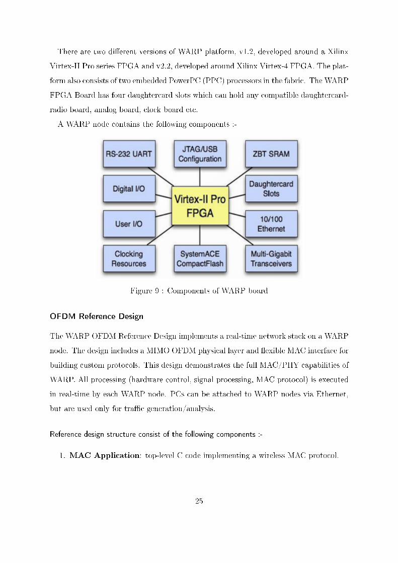
There are two di�erent versions of WARP platform, v1.2, developed around a Xilinx
Virtex-II Pro series FPGA and v2.2, developed around Xilinx Virtex-4 FPGA. The plat-
form also consists of two embedded PowerPC (PPC) processors in the fabric. The WARP
FPGA Board has four daughtercard slots which can hold any compatible daughtercard-
radio board, analog board, clock board etc.
A WARP node contains the following components :-
Figure 9 : Components of WARP board
OFDM Reference Design
The WARP OFDM Reference Design implements a real-time network stack on a WARP
node. The design includes a MIMO OFDM physical layer and �exible MAC interface for
building custom protocols. This design demonstrates the full MAC/PHY capabilities of
WARP. All processing (hardware control, signal processing, MAC protocol) is executed
in real-time by each WARP node. PCs can be attached to WARP nodes via Ethernet,
but are used only for tra�c generation/analysis.
Reference design structure consist of the following components :-
1. MAC Application: top-level C code implementing a wireless MAC protocol.
25
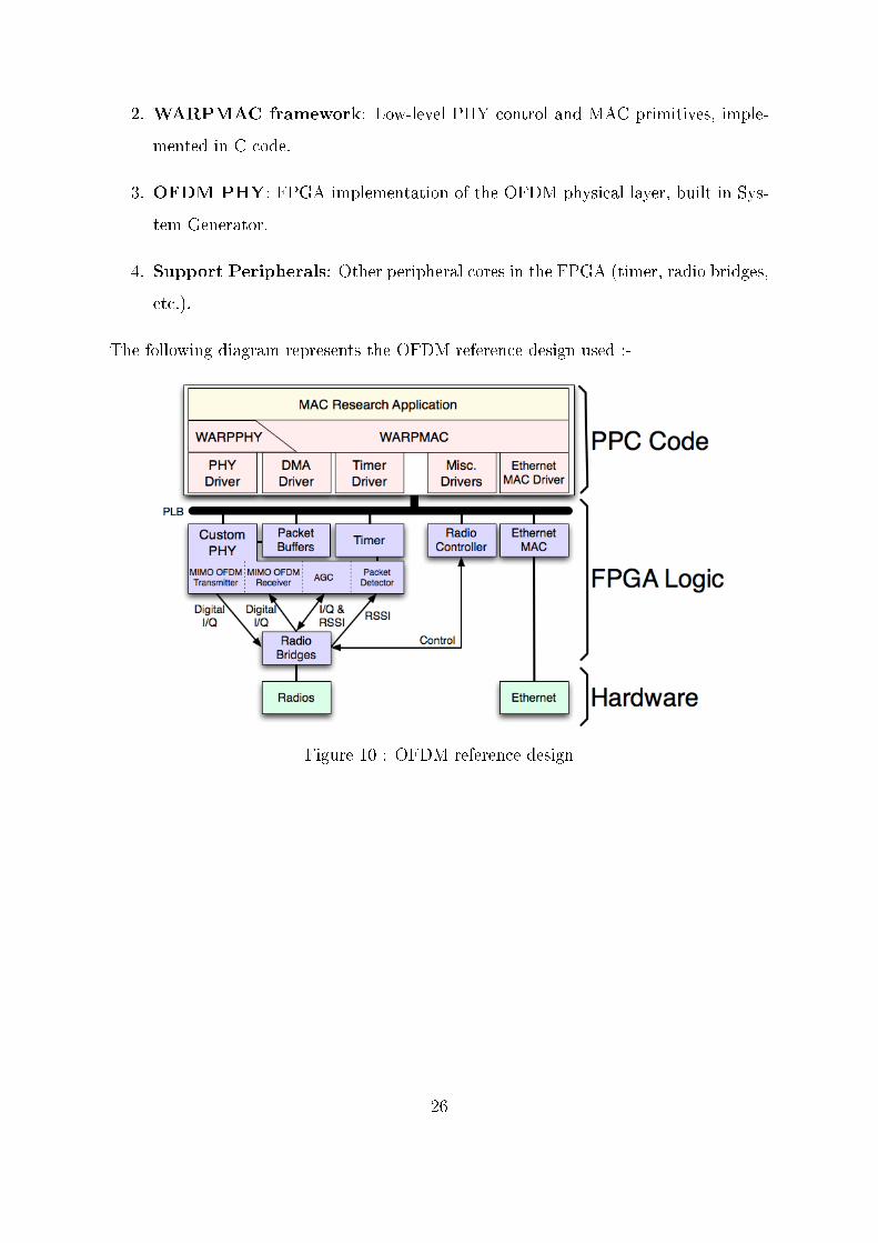
2. WARPMAC framework: Low-level PHY control and MAC primitives, imple-
mented in C code.
3. OFDM PHY: FPGA implementation of the OFDM physical layer, built in Sys-
tem Generator.
4. Support Peripherals: Other peripheral cores in the FPGA (timer, radio bridges,
etc.).
The following diagram represents the OFDM reference design used :-
Figure 10 : OFDM reference design
26
6 Experiments & Result
6.1 Using Iperf
The following experiments were performed by creating Iperf server on SS and Iperf client
on the BS. Similar results were obtained when we do the reverse
Following experiments were performed :-
1. UDP Transfer comparisions at di�erent bandwidth
2. TCP Transfer comparisions
3. UDP and TCP simultaneous transfer considering UDP as high priority
4. UDP and TCP simultaneous transfer considering TCP as high priority
For experiment 1 and 2 at a time either UDP or TCP transfer was done. The scenario
considered was SS acting as server and BS acting as client. Similar results were obtain
on role reversal. The jitter, throughput and loss of UDP transfer were almost similar
for previous and Qos code. TCP result were also found to be similar. This ensures that
the code implemented do not have any additional visible overhead. These experiment
was done to ensure the correct working of the network as required.
The observation made have been presented in a tabulated and graphical format
6.1.1 Only UDP transfer
This experiment involves transfer of only UDP packets in the network. The bandwidth
was varied to �nd out the throughput, jitter and loss. After some limit of bandwidth
27
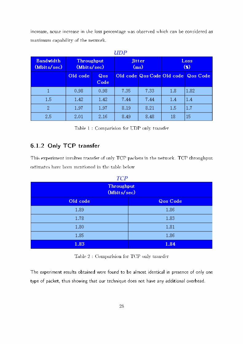
increase, acute increase in the loss percentage was observed which can be considered as
maximum capability of the network.
Table 1 : Comparision for UDP only transfer
6.1.2 Only TCP transfer
This experiment involves transfer of only TCP packets in the network. TCP throughput
estimates have been mentioned in the table below
Table 2 : Comparision for TCP only transfer
The experiment results obtained were found to be almost identical in presence of only one
type of packet, thus showing that our technique does not have any additional overhead.
28
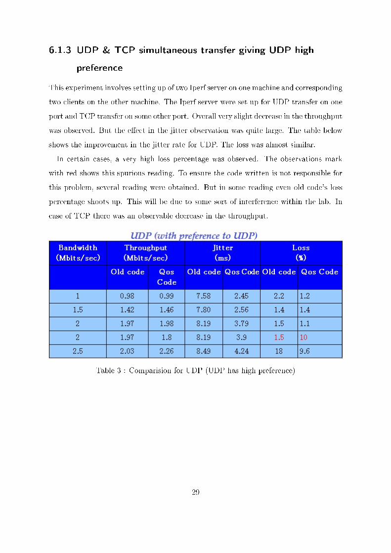
6.1.3 UDP & TCP simultaneous transfer giving UDP high
preference
This experiment involves setting up of two Iperf server on one machine and corresponding
two clients on the other machine. The Iperf server were set up for UDP transfer on one
port and TCP transfer on some other port. Overall very slight decrease in the throughput
was observed. But the e�ect in the jitter observation was quite large. The table below
shows the improvement in the jitter rate for UDP. The loss was almost similar.
In certain cases, a very high loss percentage was observed. The observations mark
with red shows this spurious reading. To ensure the code written is not responsible for
this problem, several reading were obtained. But in some reading even old code's loss
percentage shoots up. This will be due to some sort of interference within the lab. In
case of TCP there was an observable decrease in the throughput.
Table 3 : Comparision for UDP (UDP has high preference)
29
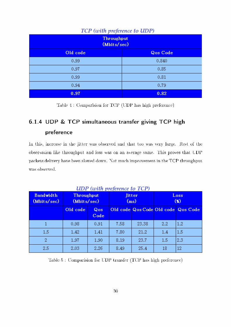
Table 4 : Comparision for TCP (UDP has high preference)
6.1.4 UDP & TCP simultaneous transfer giving TCP high
preference
In this, increase in the jitter was observed and that too was very large. Rest of the
observation like throughput and loss was on an average same. This proves that UDP
packets delivery have been slowed down. Not much improvement in the TCP throughput
was observed.
Table 5 : Comparision for UDP transfer (TCP has high preference)
30
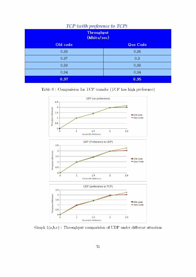
Table 6 : Comparision for TCP transfer (TCP has high preference)
Graph 1(a,b,c) : Throughput comparision of UDP under di�erent situation
31
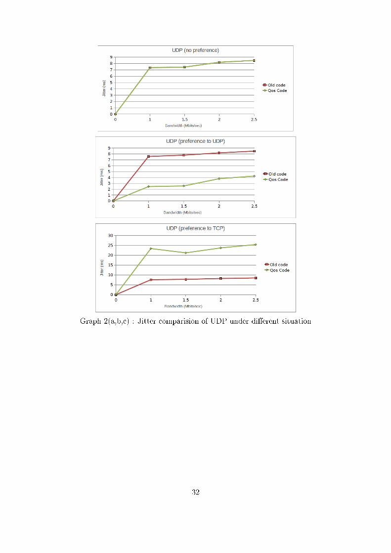
Graph 2(a,b,c) : Jitter comparision of UDP under di�erent situation
32
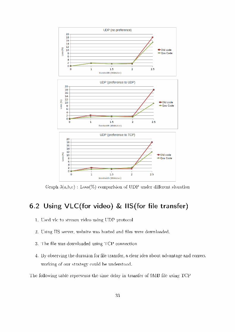
Graph 3(a,b,c) : Loss(%) comparision of UDP under di�erent situation
6.2 Using VLC(for video) & IIS(for �le transfer)
1. Used vlc to stream video using UDP protocol
2. Using IIS server, website was hosted and �les were downloaded.
3. The �le was downloaded using TCP connection
4. By observing the duration for �le transfer, a clear idea about advantage and correct
working of our strategy could be understood.
The following table represents the time delay in transfer of 9MB �le using TCP
33
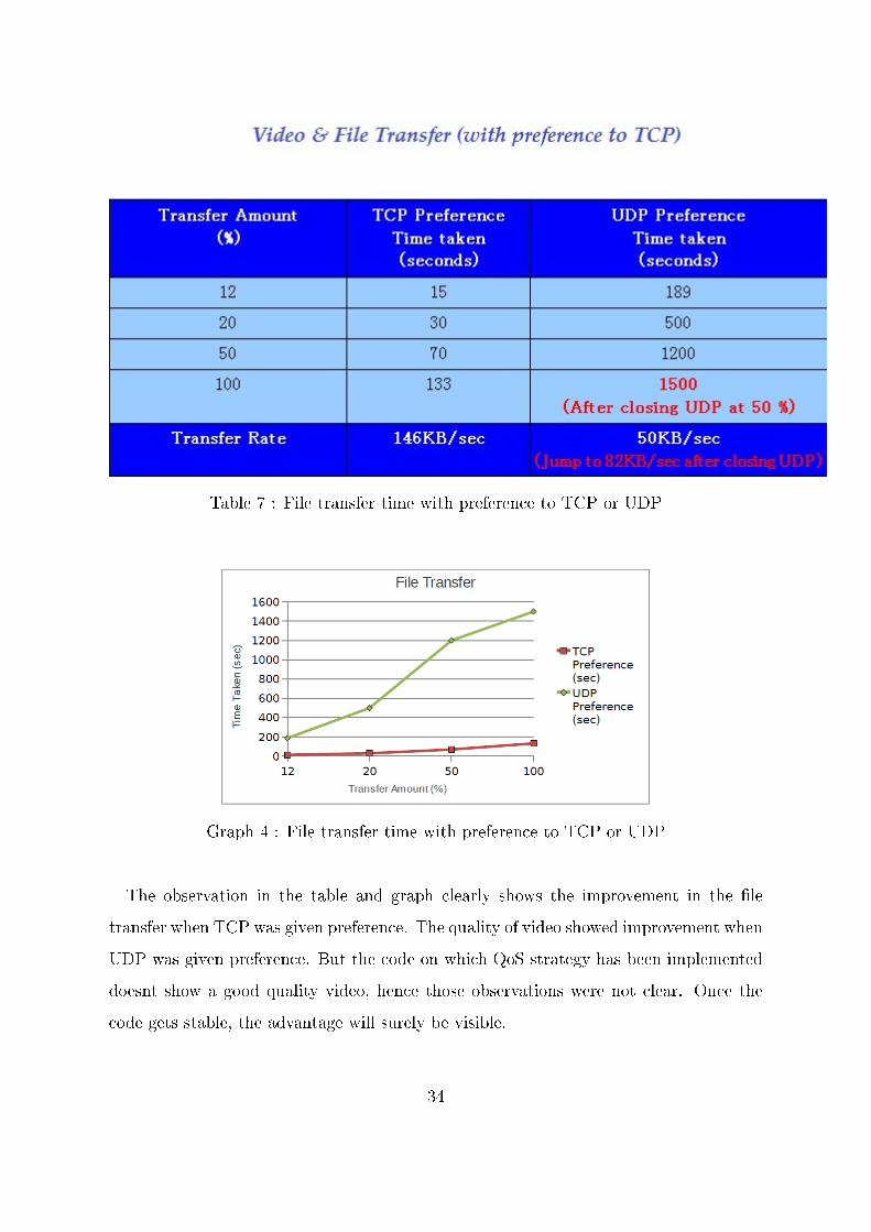
Table 7 : File transfer time with preference to TCP or UDP
Graph 4 : File transfer time with preference to TCP or UDP
The observation in the table and graph clearly shows the improvement in the �le
transfer when TCP was given preference. The quality of video showed improvement when
UDP was given preference. But the code on which QoS strategy has been implemented
doesnt show a good quality video, hence those observations were not clear. Once the
code gets stable, the advantage will surely be visible.
34
6.3 Slotting Pattern
Di�erentiated slotting pattern was also implemented and currently to a single SS, two
continuous slots have been alloted. The result could not be veri�ed because of some hard-
ware issues(connectors) as the experimentation on this kind of setup requires atleast 3
node. But when testing was done for 2 nodes the result were found to be encouraging. A
single SS transmit in both the slots and these results could be veri�ed through wireshark.
35
7 Conclusion & Future Work
The following can be concluded from the experiments done :-
1. QoS strategy developed provides di�erentiated services
2. Priority are on the basis of type of data
3. Experiments done specially using video and �le transfer clearly shows the e�ec-
tiveness of the strategy
4. Priority on the basis of Subscriber Station has been provided
5. TCP �le transfer took very less time when TCP has high preference as compared
to UDP having high preference
6. Weighted fair Queue strategy doesnt show much improvement in observation which
are observable. But this strategy can also be employed depeding on the require-
ment
7. Strict Queue strategy code is currently integrated with the WiMAX code.
8. The strategy for dynamically allotment of di�erentiated service is the next goal to
be completed.
36
Bibliography
[1] Jerey G. Andrews et. al., �Fundamentals of WiMAX�,Prentice Hall Publications
[2] �http://warp.rice.edu/trac/wiki�, Rice University - Wireless Open Access Research
Platform
[3] Vinay Yadav, �SCMax : Design & Implementation of MAC layer for WiMAX based
Relay Network�, MTP report
[4] Vasu Dev Sharma, �RD WiReNet : Design and Implementation of a Rapidly De-
ployable WiMAX Relay Network�, MTP report
[5] Wu Lin,Zhang Luyuong & Wang Rui, �A novel and E�ective Qos Guarantee Scheme
in Wimax System �,IEEE,2010
[6] Vishal Sevani, �Optimizing QoS In FRACTEL:A TDMA Based Wi� Mesh Network
for rural Digital connectivity�, IIT Bombay
37