Embed Size (px)
Citation preview
E-blocks TM Quad Band GSM/GPRS board
Document code: EB066-30-1
Copyright © 2011 Matrix Multimedia Limited 1
Quad Band GSM/GPRS board datasheet Quad Band GSM/GPRS board datasheet Quad Band GSM/GPRS board datasheet Quad Band GSM/GPRS board datasheet EB066EB066EB066EB066----00000000----1111
CONTENTSCONTENTSCONTENTSCONTENTS
1. About this document………………………………………………………. 2 2. General Information……………………………………………………….. 3 3. Board layout………………………………………………………………... 3 4. Testing this product………………………………………………………... 4 5. Circuit description………………………………………………………….. 4
Appendix 1 Circuit diagram.
E-blocks TM Quad Band GSM/GPRS board
Document code: EB066-30-1
Copyright © 2011 Matrix Multimedia Limited 2
1. 1. 1. 1. About This DocumentAbout This DocumentAbout This DocumentAbout This Document This document concerns the Matrix Multimedia Quad Band GSM/GPRS board, order code EB066-00-1.
1. Trademarks and Trademarks and Trademarks and Trademarks and copyrightcopyrightcopyrightcopyright
PIC and PICmicro are registered trademarks of Arizona Microchip Inc. E-blocks is a trademark of Matrix Multimedia Limited. EB066 and associated software and documentation are Copyright ©2011 Matrix Multimedia Limited.
2. Other Sources of InformaOther Sources of InformaOther Sources of InformaOther Sources of Informationtiontiontion
There are various other documents and sources that you may find useful: Getting Started with EGetting Started with EGetting Started with EGetting Started with E----Blocks.pdfBlocks.pdfBlocks.pdfBlocks.pdf This describes the E-block system and how it can be used to develop complete systems for learning electronics and for PICmicro programming. PPPPPP Help FilePP Help FilePP Help FilePP Help File This describes the PPP software and its functionality. PPP software is used for transferring hex code to a PICmicro microcontroller. C and Assembly StrategiesC and Assembly StrategiesC and Assembly StrategiesC and Assembly Strategies For strategy information for creating ‘C’ and Assembly code for the Quad relay board see members area. This can be found at www.matrixmultimedia.com/eblocks
3. DisclaimerDisclaimerDisclaimerDisclaimer
The information provided within this document was correct at the time of going to press. Matrix Multimedia reserves the right to change specifications from time to time.
4. Technical SupportTechnical SupportTechnical SupportTechnical Support If you have any problems operating this product then please refer to the troubleshooting section of this document first. You will find the latest software updates, FAQs and other information on our web site: www.matrixmultimedia.co.uk.
E-blocks TM Quad Band GSM/GPRS board
Document code: EB066-30-1
Copyright © 2011 Matrix Multimedia Limited 3
1.1.1.1. General informationGeneral informationGeneral informationGeneral information
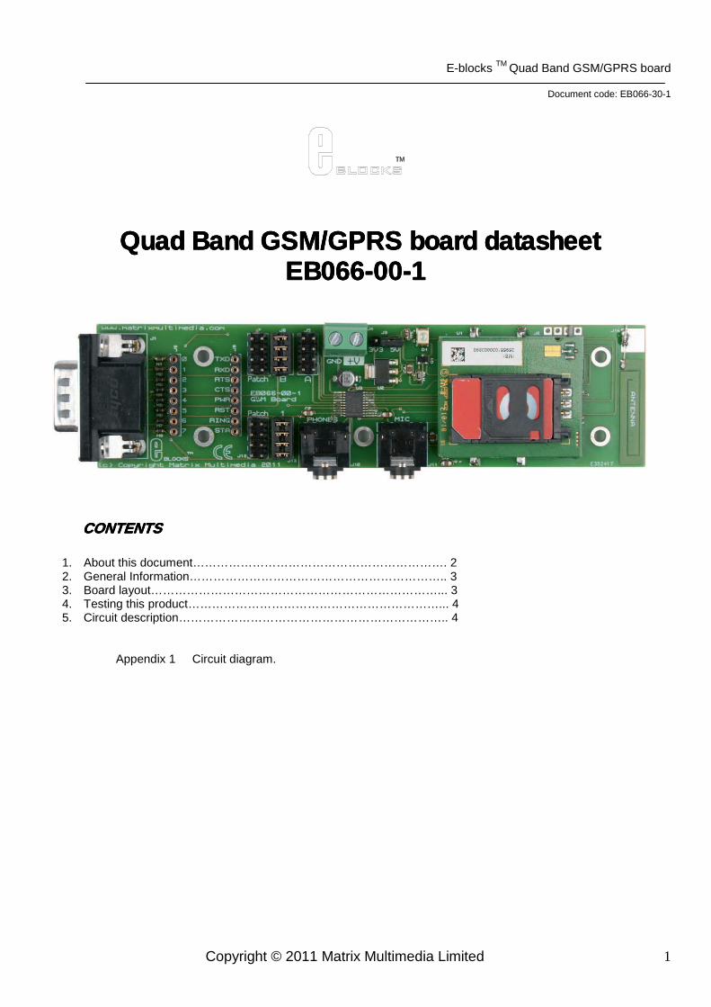
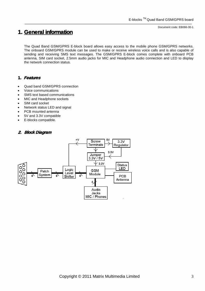
The Quad Band GSM/GPRS E-block board allows easy access to the mobile phone GSM/GPRS networks. The onboard GSM/GPRS module can be used to make or receive wireless voice calls and is also capable of sending and receiving SMS text messages. The GSM/GPRS E-block comes complete with onboard PCB antenna, SIM card socket, 2.5mm audio jacks for MIC and Headphone audio connection and LED to display the network connection status.
1. 1. 1. 1. FeaturesFeaturesFeaturesFeatures
• Quad band GSM/GPRS connection • Voice communications • SMS text based communications • MIC and Headphone sockets • SIM card socket • Network status LED and signal • PCB mounted antenna • 5V and 3.3V compatible • E-blocks compatible. 2.2.2.2. Block DiagramBlock DiagramBlock DiagramBlock Diagram
E-blocks TM Quad Band GSM/GPRS board
Document code: EB066-30-1
Copyright © 2011 Matrix Multimedia Limited 4
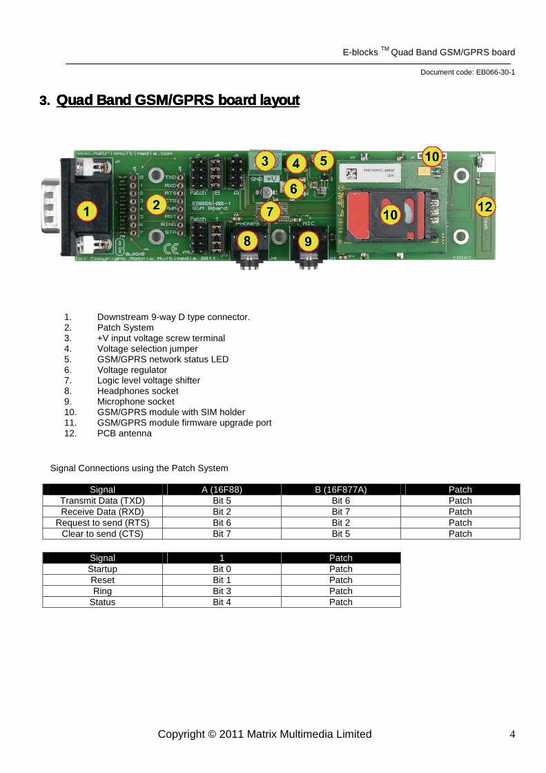
3.3.3.3. Quad Band GSM/GPRS board layoutQuad Band GSM/GPRS board layoutQuad Band GSM/GPRS board layoutQuad Band GSM/GPRS board layout
1. Downstream 9-way D type connector. 2. Patch System 3. +V input voltage screw terminal 4. Voltage selection jumper 5. GSM/GPRS network status LED 6. Voltage regulator 7. Logic level voltage shifter 8. Headphones socket 9. Microphone socket 10. GSM/GPRS module with SIM holder 11. GSM/GPRS module firmware upgrade port 12. PCB antenna
Signal Connections using the Patch System
Signal A (16F88) B (16F877A) Patch Transmit Data (TXD) Bit 5 Bit 6 Patch Receive Data (RXD) Bit 2 Bit 7 Patch
Request to send (RTS) Bit 6 Bit 2 Patch Clear to send (CTS) Bit 7 Bit 5 Patch
Signal 1 Patch Startup Bit 0 Patch Reset Bit 1 Patch Ring Bit 3 Patch
Status Bit 4 Patch
E-blocks TM Quad Band GSM/GPRS board
Document code: EB066-30-1
Copyright © 2011 Matrix Multimedia Limited 5
4.4.4.4. Testing This ProduTesting This ProduTesting This ProduTesting This Productctctct
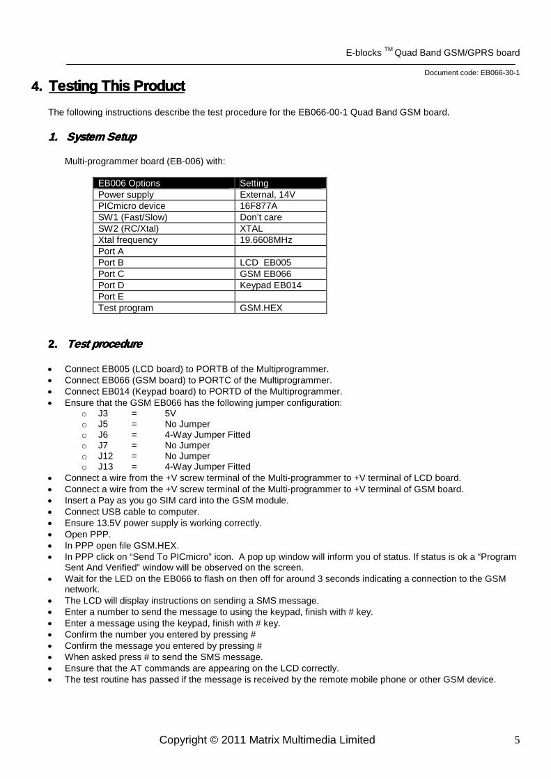
The following instructions describe the test procedure for the EB066-00-1 Quad Band GSM board. 1.1.1.1. System SetupSystem SetupSystem SetupSystem Setup
Multi-programmer board (EB-006) with:
EB006 Options Setting Power supply External, 14V PICmicro device 16F877A SW1 (Fast/Slow) Don’t care SW2 (RC/Xtal) XTAL Xtal frequency 19.6608MHz Port A Port B LCD EB005 Port C GSM EB066 Port D Keypad EB014 Port E Test program GSM.HEX
2. 2. 2. 2. Test procedureTest procedureTest procedureTest procedure
• Connect EB005 (LCD board) to PORTB of the Multiprogrammer. • Connect EB066 (GSM board) to PORTC of the Multiprogrammer. • Connect EB014 (Keypad board) to PORTD of the Multiprogrammer. • Ensure that the GSM EB066 has the following jumper configuration:
o J3 = 5V o J5 = No Jumper o J6 = 4-Way Jumper Fitted o J7 = No Jumper o J12 = No Jumper o J13 = 4-Way Jumper Fitted
• Connect a wire from the +V screw terminal of the Multi-programmer to +V terminal of LCD board. • Connect a wire from the +V screw terminal of the Multi-programmer to +V terminal of GSM board. • Insert a Pay as you go SIM card into the GSM module. • Connect USB cable to computer. • Ensure 13.5V power supply is working correctly. • Open PPP. • In PPP open file GSM.HEX. • In PPP click on “Send To PICmicro” icon. A pop up window will inform you of status. If status is ok a “Program
Sent And Verified” window will be observed on the screen. • Wait for the LED on the EB066 to flash on then off for around 3 seconds indicating a connection to the GSM
network. • The LCD will display instructions on sending a SMS message. • Enter a number to send the message to using the keypad, finish with # key. • Enter a message using the keypad, finish with # key. • Confirm the number you entered by pressing # • Confirm the message you entered by pressing # • When asked press # to send the SMS message. • Ensure that the AT commands are appearing on the LCD correctly. • The test routine has passed if the message is received by the remote mobile phone or other GSM device.
E-blocks TM Quad Band GSM/GPRS board
Document code: EB066-30-1
Copyright © 2011 Matrix Multimedia Limited 6
5. 5. 5. 5. Circuit DescriptionCircuit DescriptionCircuit DescriptionCircuit Description
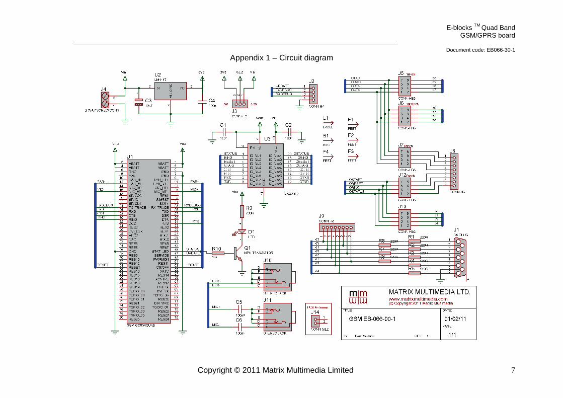
The EB066 Quad Band GSM circuit can be observed in Appendix1.
1. AT Commands
The GSM module uses a serial connection to transfer commands and data to and from the microcontroller. To do this there is a standard called AT commands which the microcontroller uses to perform functions on the GSM. AT commands are simply strings of serial data starting with the characters “AT” standing for “Attention”. Here are some of the more generic AT commands available on the GSM module. ATD07712345678; - dial the number specified ATA - answer an incoming call ATH - disconnect an active call For a list of all the supported AT commands please refer to the datasheet available from here. http://www.telit.com/module/infopool/download.php?id=542
2. 5V / 3.3V Operation
The GSM module requires a supply voltage of 3.3V and I/O signal voltage of 3.3V. To allow the module to work with 5V systems a voltage shifting circuit has been fitted onto the board. Care must be taken to ensure the voltage selection jumper is in the 5V position before powering up the board with a supply voltage greater then 3.3V. NoteNoteNoteNote:::: Running the board with the voltage jumper in the 3.3V position with any other input voltage then 3.3V is likely to cause irreversible damage to the GSM module and level shifting circuitry.
3. SIM Card socket
SIM cards used with the module must be pre-pay (“Pay As You Go”) rather then contract based as contract based SIM cards are normally heavily encrypted by the service provider.
4. Start / Reset Signals
Driving the reset signal low will cause the module to reset and require starting up again. To allow the GSM module to start up the reset signal and start signal must be driven high by the microcontroller. Once the start and reset signals have been driven high the start signal must be driven low for at least 3 seconds before being driven high again. This procedure must be followed every time the module is reset to allow it to come back online and allow communications. The module should be active on power on without requiring a reset.
5. Status LED
The LED on the board will flash every second when the GSM module is trying to establish communications with the GSM network. Once the communications have been established and a good signal is being received the LED will flash quickly and then remain off for around 3 seconds. The GSM network status is also available via one of the data lines so the microcontroller controlling the system can detect if the module has a valid signal or not. When the module is in a call or communicating with the GSM network the LED will remain lit.
6. Onboard Antenna The onboard antenna is fairly low gain and is provided to allow simple GSM communications in strong signal areas. For weaker signal areas it is advisable to remove the GSM module from the E-block, disconnect the onboard antenna from the module and then connect a high gain quad band GSM antenna to the module. The antenna socket on the GSM module is a Murata GSC type wireless connector.
E-blocks TM Quad Band GSM/GPRS board
Document code: EB066-30-1
Copyright © 2011 Matrix Multimedia Limited 7
Appendix 1 – Circuit diagram


![DATA SHEET SKY77328 iPAC™ PAM for Quad-Band GSM / GPRS · 2019-02-14 · DATA SHEET SKY77328 iPAC™ PAM FOR QUAD-BAND GSM / GPRS Skyworks Solutions, Inc. • Phone [781] 376-3000](https://img.pdfslide.net/doc/110x75/5ea4f8f67c359e00513582f8/data-sheet-sky77328-ipaca-pam-for-quad-band-gsm-gprs-2019-02-14-data-sheet.jpg)