Embed Size (px)
Citation preview
www.matrixmultimedia.com
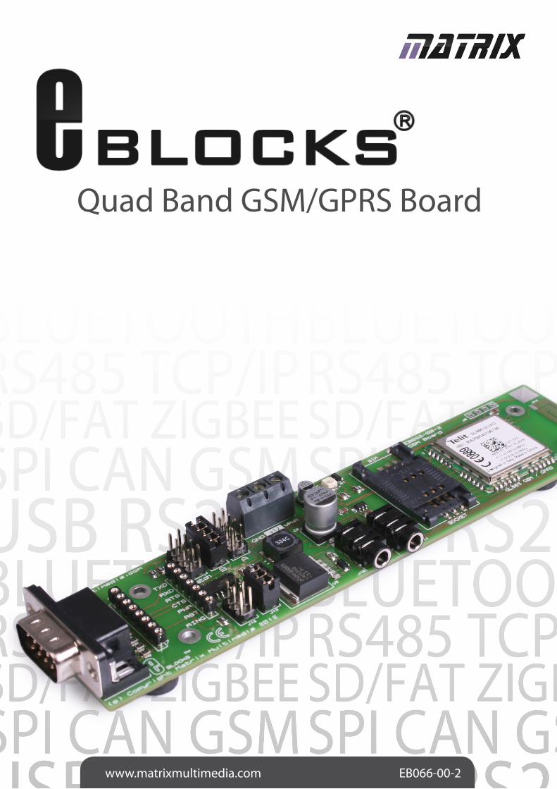
Quad Band GSM/GPRS Board
EB066-00-2
2 Copyright © Matrix Multimedia Ltd.
Contents
About This Document 2General Information 3Board Layout 4Testing This Product 5Circuit Description 6Circuit Diagram 7
This document concerns the Matrix Multimedia Quad Band GSM/GPRS board, order code EB066-00-2.
1. Trademarks and copyrightPIC and PICmicro are registered trademarks of Arizona Microchip Inc. E-blocks is a trademark of Matrix Multimedia Ltd.
2. DisclaimerThe information provided within this document is correct at the time of going to press. Matrix Multimedia reserves the right to change specifications from time to time.
• How to get started with E-blocks - if you are new to E-blocks and wish to learn how to use them from the beginning there are resources available to help.
• Relevant software and hardware that allow you to use your E-blocks product better.
• Example files and programs.• Ways to get technical support for your product, either
via the forums or by contacting us directly.
3. Testing this productIt is advisable to test the product upon receiving it to ensure it works correctly. Matrix provides test procedures for all E-blocks, which can be found in the Support section of the website.
4. Product supportIf you require support for this product then please visit the Matrix website, which contains many learning resources for the E-blocks series. On our website you will find:
About This Document
3 Copyright © Matrix Multimedia Ltd.
General Information
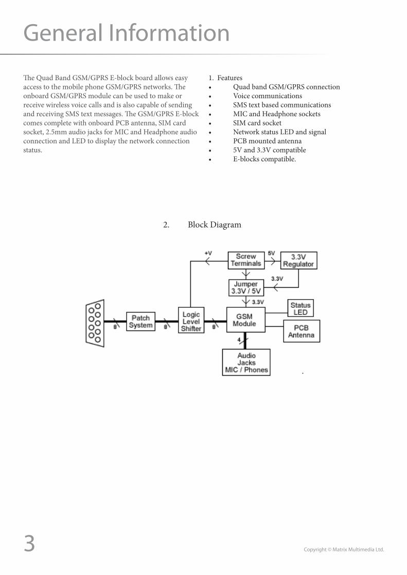
The Quad Band GSM/GPRS E-block board allows easy access to the mobile phone GSM/GPRS networks. The onboard GSM/GPRS module can be used to make or receive wireless voice calls and is also capable of sending and receiving SMS text messages. The GSM/GPRS E-block comes complete with onboard PCB antenna, SIM card socket, 2.5mm audio jacks for MIC and Headphone audio connection and LED to display the network connection status.
1. Features • QuadbandGSM/GPRSconnection• Voicecommunications• SMStextbasedcommunications• MICandHeadphonesockets• SIMcardsocket• NetworkstatusLEDandsignal• PCBmountedantenna• 5Vand3.3Vcompatible• E-blockscompatible.
2. Block Diagram
Copyright © Matrix Multimedia Ltd.4
Board Layout
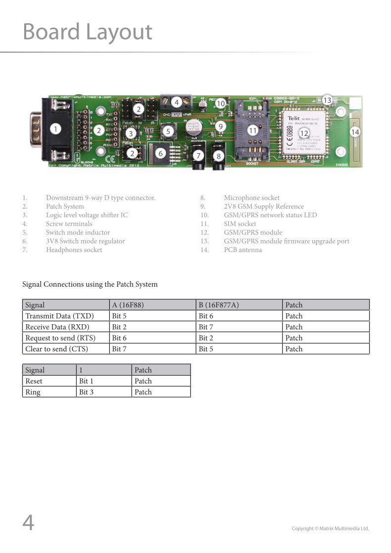
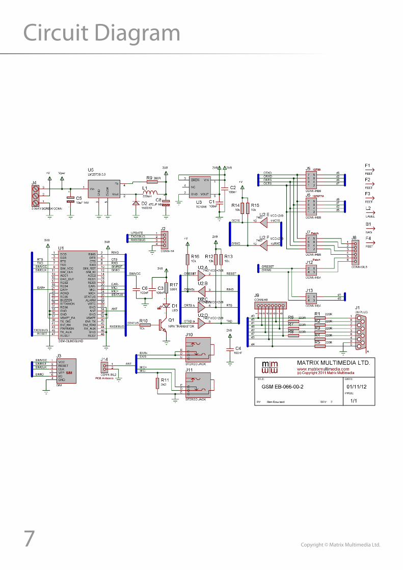
1. Downstream 9-way D type connector. 2. Patch System3. LogiclevelvoltageshifterIC4. Screw terminals5. Switch mode inductor6. 3V8Switchmoderegulator7. Headphones socket
8. Microphonesocket9. 2V8GSMSupplyReference10. GSM/GPRS network status LED 11. SIM socket12. GSM/GPRS module13. GSM/GPRSmodulefirmwareupgradeport14. PCB antenna
1 2 3
2
2
6
5
4
7 8
9
10
11 12
13
14
Signal Connections using the Patch System
Signal A(16F88) B(16F877A) PatchTransmitData(TXD) Bit 5 Bit 6 PatchReceiveData(RXD) Bit 2 Bit 7 PatchRequesttosend(RTS) Bit 6 Bit 2 PatchCleartosend(CTS) Bit 7 Bit 5 Patch
Signal 1 PatchReset Bit 1 PatchRing Bit3 Patch
5 Copyright © Matrix Multimedia Ltd.
Testing This Product
The following instructions describe the test procedure for the EB066-00-2 Quad Band GSM board.
1. System Setup
Multi-programmerboard(EB-006)with:
EB006 Options SettingPower supply External,14VPICmicro device 16F877ASW1(Fast/Slow) Don’t careSW2(RC/Xtal) XTALXtal frequency 19.6608MHzPort APort B LCD EB005Port C GSM EB066Port D Keypad EB014Port ETest program GSM.HEX
2. Test procedure
• ConnectEB005(LCDboard)toPORTBoftheMultiprogrammer.• ConnectEB066(GSMboard)toPORTCoftheMultiprogrammer.• ConnectEB014(Keypadboard)toPORTDoftheMultiprogrammer.• EnsurethattheGSMEB066hasthefollowingjumperconfiguration:o J5 = NoJumpero J6 = 4-Way Jumper Fittedo J7 = NoJumpero J12 = NoJumpero J13 = 4-WayJumperFitted
• Connectawirefromthe+VscrewterminaloftheMulti-programmerto+VterminalofLCDboard.• Connectawirefromthe+VscrewterminaloftheMulti-programmerto+VterminalofGSMboard.• Connectawirefromthe14VscrewterminaloftheMulti-programmerto+VPWRterminalofGSMboard.• Inserta“Payasyougo”typeSIMcardintotheGSM module (contract SIMs are encrypted and won’t work).• ConnectUSBcabletocomputer.• Ensure13.5Vpowersupplyisworkingcorrectly.• OpenPPP.• InPPPopenfileGSM.HEX.• InPPPclickon“SendToPICmicro”icon.Apopupwindowwillinformyouofstatus.Ifstatusisoka“Pro-gramSentAndVerified”windowwillbeobservedonthescreen.• WaitfortheLEDontheEB066toflashonthenoffforaround3secondsindicatingaconnectiontotheGSM network.• TheLCDwilldisplayinstructionsonsendingaSMS message.• Enteranumbertosendthemessagetousingthekeypad,finishwith#key.• Enteramessageusingthekeypad,finishwith#key.• Confirmthenumberyouenteredbypressing#• Confirmthemessageyouenteredbypressing#• Whenaskedpress#tosendtheSMSmessage.• EnsurethattheATcommandsareappearingonthe LCD correctly.• Thetestroutinehaspassedifthemessageisre-ceived by the remote mobile phone or other GSM device.
6 Copyright © Matrix Multimedia Ltd.
Circuit Description
1. AT Commands
The GSM module uses a serial connection to transfer commands and data to and from the microcontroller. To do this there is a standard called AT commands which the microcontroller uses to perform functions on the GSM. AT commands are simply strings of serial data starting withthecharacters“AT”standingfor“Attention”.
Here are some of the more generic AT commands avail-able on the GSM module.
ATD07712345678; -dialthenumberspecifiedATA - answer an incoming callATH - disconnect an active call
For a list of all the supported AT commands please refer to the datasheet available from here.http://www.telit.com/module/infopool/download.php?id=542
2. 5V/3.3VOperation
TheGSMmodulerequiresasupplyvoltageof3.8VandI/Osignalvoltageof2.8V.Toallowthemoduletoworkwith3V3and5Vsystemsavoltageshiftingcircuithasbeenfittedontotheboard.Caremustbetakentoconnectthe correct screw terminal to the correct voltage source.
Note:Poweringtheboardwiththeexternalvoltagessetupincorrectly is likely to cause irreversible damage to the module. Please take care when wiring up the external volt-ages to unplug your power supply and double check your connections before plugging it back in.
3. SIMCardsocket
SIMcardsusedwiththemodulemustbepre-pay(“PayAsYouGo”)ratherthencontractbasedascontractbasedSIM cards are normally heavily encrypted by the service provider.
4. Status LED
TheLEDontheboardwillflasheverysecondwhentheGSM module is trying to establish communications with the GSM network. Once the communications have been established and a good signal is being received the LEDwillflashquicklyandthenremainoffforaround3seconds. When the module is in a call or communicating with the GSM network the LED will remain constantly lit.
5. Onboard Antenna
The on-board antenna provides good signal strength even in weaker area’s so no external antenna connection has been provided.
7 Copyright © Matrix Multimedia Ltd.
Circuit Diagram
Matrix Ltd.The Factory
33 Gibbet StreetHalifax, HX1 5BA, UK
t: +44 (0)1422 252380e: [email protected]
www.matrixmultimedia.com
EB066-30-2


![DATA SHEET SKY77500 iPAC™ FEM for Quad-Band GSM · PDF fileDATA SHEET • SKY77500 IPAC™ FEM FOR QUAD-BAND GSM / GPRS Skyworks Solutions, Inc. • Phone [781] 376-3000 • Fax](https://img.pdfslide.net/doc/110x75/5aa5b80d7f8b9a2f048dc4e1/data-sheet-sky77500-ipac-fem-for-quad-band-gsm-sheet-sky77500-ipac.jpg)