Embed Size (px)
Citation preview
1
Quadrature Amplitude Modulated Backscatter inPassive and Semi-Passive UHF RFID Systems
Stewart J. Thomas, Student Member, IEEE, Eric Wheeler, Jochen Teizer,and Matthew S. Reynolds, Senior Member, IEEE
Abstract—Passive and semi-passive UHF RFID systems havetraditionally been designed using scalar-valued differential radarcross section (DRCS) methods to model the backscattered signalfrom the tag. This paper argues that scalar-valued DRCS analysisis unnecessarily limiting because of the inherent coherence ofthe backscatter link and the complex-valued nature of load-dependent antenna-mode scattering from an RFID tag. Consider-ing modulated backscatter in terms of complex-valued scatteredfields opens the possibility of quadrature modulation of thebackscatter channel.
When compared with binary ASK or PSK based RFID systemswhich transmit one bit of data per symbol period, and thus onebit per on-chip clock oscillator period, tags employing vectorbackscatter modulation can transmit more than one bit persymbol period. This increases the data rate for a given on-chipsymbol clock rate leading to reduced on-chip power consumptionand extended read range. Alternatively, tags employing an M -ary modulator can achieve log2 M higher data throughput atessentially the same DC power consumption as a tag employingbinary ASK or PSK.
In contrast to the binary ASK or PSK backscatter modulationemployed by passive and semi-passive UHF RFID tags, such astags compliant with the widely used ISO18000-6c standard, thispaper explores a novel CMOS-compatible method for generatingM -ary QAM backscatter modulation. A new method is presentedfor designing an inductorless M -ary QAM backscatter modulatorusing only an array of switched resistances and capacitances.Device-level simulation and measurements of a 4-PSK/4-QAMmodulator are provided for a semi-passive (battery-assisted)tag operating in the 850-950 MHz band. This first prototypemodulator transmits 4-PSK/4-QAM at a symbol rate of 200kHzand a bit rate of 400kbps at a static power dissipation of only115 nW.
Index Terms—QAM backscatter, Passive RFID tags, CMOSintegrated circuits, Backscatter, Quadrature amplitude modula-tion, UHF RFID, backscatter phase rotation
I. INTRODUCTION
ULTRAHIGH frequency (UHF) radio frequency identifi-cation (RFID) systems employing modulated backscatter
communication links, such as those based on the widelydeployed ISO18000-6c or EPC Global Class 1 Generation 2specification [1], have traditionally been analyzed using tech-niques first developed to analyze radar systems. This paperdemonstrates that scalar valued differential radar cross section(RCS) techniques are unnecessarily limiting for RFID systemanalysis because of the inherent coherence of the backscatterlink and the complex-valued nature of load dependent scatter-ing from an RFID tag’s antenna.
In most commonly deployed UHF RFID systems, the UHFbackscatter link employs a simple binary modulation scheme,such as ASK or PSK backscatter generated by a two-state
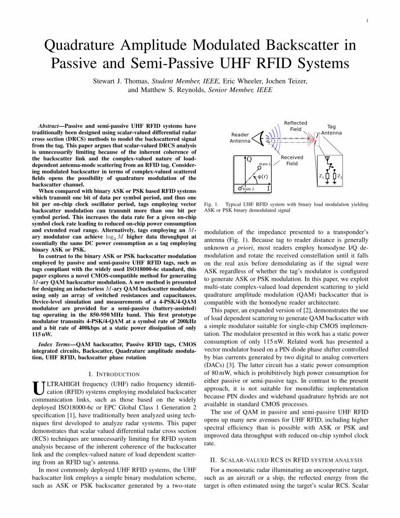
Fig. 1. Typical UHF RFID system with binary load modulation yieldingASK or PSK binary demodulated signal
modulation of the impedance presented to a transponder’santenna (Fig. 1). Because tag to reader distance is generallyunknown a priori, most readers employ homodyne I/Q de-modulation and rotate the received constellation until it fallson the real axis before demodulating as if the signal wereASK regardless of whether the tag’s modulator is configuredto generate ASK or PSK modulation. In this paper, we exploitmulti-state complex-valued load dependent scattering to yieldquadrature amplitude modulation (QAM) backscatter that iscompatible with the homodyne reader architecture.
This paper, an expanded version of [2], demonstrates the useof load dependent scattering to generate QAM backscatter witha simple modulator suitable for single-chip CMOS implemen-tation. The modulator presented in this work has a static powerconsumption of only 115 nW. Related work has presented avector modulator based on a PIN diode phase shifter controlledby bias currents generated by two digital to analog converters(DACs) [3]. The latter circuit has a static power consumptionof 80 mW, which is prohibitively high power consumption foreither passive or semi-passive tags. In contrast to the presentapproach, it is not suitable for monolithic implementationbecause PIN diodes and wideband quadrature hybrids are notavailable in standard CMOS processes.
The use of QAM in passive and semi-passive UHF RFIDopens up many new avenues for UHF RFID, including higherspectral efficiency than is possible with ASK or PSK andimproved data throughput with reduced on-chip symbol clockrate.
II. SCALAR-VALUED RCS IN RFID SYSTEM ANALYSIS
For a monostatic radar illuminating an uncooperative target,such as an aircraft or a ship, the reflected energy from thetarget is often estimated using the target’s scalar RCS. Scalar
2
RCS in this context is simply a measure of the target’sstructural scattering at a particular attitude with respect to theradar. RCS is defined in terms of incident and scattered fields
� = lim
r!1
4⇡r
2 |Es|2
|Ei|2
�(1)
where r is the radar to target separation and E
s,i are thescattered and incident electric fields at the target. Assumingfree space propagation between the radar and the target, theradar equation is then employed to estimate the magnitude ofthe received signal due to radar illumination of the target
Pr =
PTGTGR�2�
(4⇡)
3r
4(2)
where � is target RCS as previously defined, PR, PT are signalpower at the radar’s receiver and transmitter, GR, GT are thegains of the radar’s receive and transmit antennas, and � isthe radar’s wavelength.
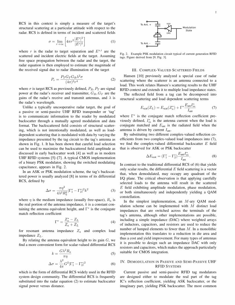
Unlike a typically uncooperative radar target, the goal ofa passive or semi-passive UHF RFID transponder or ‘tag’is to communicate information to the reader by modulatedbackscatter through a mutually agreed modulation and dataformat. The backscattered field consists of structural scatter-ing, which is not intentionally modulated, as well as load-dependent scattering that is modulated with data by varying theimpedance presented by the tag circuit to the tag’s antenna asshown in Fig. 1. It has been shown that careful load selectioncan be used to maximize the backscattered field amplitude asdiscussed in early backscatter work [4] as well as in modernUHF RFID systems [5]–[7]. A typical CMOS implementationof a binary PSK modulator, showing the switched modulatingcapacitance, appears in Fig. 2.
In an ASK or PSK modulation scheme, the tag’s backscat-tered power is usually analyzed [8] in terms of its differentialRCS, defined by
�� =
⇡⌘
2
4�
2R
2a
|�⇤1 � �
⇤2|2k2 (3)
where ⌘ is the medium impedance (usually free-space), Ra isthe real portion of the antenna impedance, k is a constant con-taining the antenna equivalent height, and �
⇤ is the conjugatematch reflection coefficient
�
⇤=
Z
⇤a � ZL
Za + ZL(4)
for resonant antenna impedance Za and complex loadimpedance ZL.
By relating the antenna equivalent height to its gain G, wefind a more convenient form for scalar-valued differential RCS
k =
G�
2Ra
⇡⌘
(5)
�� =
�
2
4⇡
G
2|�⇤1 � �
⇤2|2 (6)
which is the form of differential RCS widely used in the RFIDsystem design community. The differential RCS is frequentlysubstituted into the radar equation (2) to estimate backscattersignal power versus distance.
Fig. 2. Example PSK modulation circuit typical of current generation RFIDtags. Figure derived from [9, Fig. 3].
III. COMPLEX-VALUED SCATTERED FIELDS
Hansen [10] previously analyzed a special case of radarscattering where the scatterer is an antenna connected to aload. This work relates Hansen’s scattering results to the UHFRFID context and extends it to multiple load impedance states.
The reflected field from a tag can be decomposed intostructural scattering and load dependent scattering terms
Escat(ZL) = Escat(Z⇤a) + �
⇤EantI⇤m
Iant(7)
where �
⇤ is the conjugate match reflection coefficient pre-viously defined, I⇤m is the antenna current when the load isconjugate matched and Eant is the radiated field when theantenna is driven by current Iant.
By substituting two different complex-valued reflection co-efficients from two complex-valued load impedances into (7),we find the complex-valued differential backscatter E fieldthat is observed for ASK or PSK backscatter
�Escat = (�
⇤1 � �
⇤2)EantI
⇤m
Iant. (8)
In contrast to the traditional differential RCS of (6) that yieldsonly scalar results, the differential E field scattering is a vectorthat, when demodulated, may occupy any quadrant of theI/Q plane. The critical observation is that applying carefullyselected loads to the antenna will result in the scatteredE field exhibiting amplitude modulation, phase modulation,or both simultaneously and independently yielding a QAMconstellation.
In the simplest implementation, an M -ary QAM mod-ulation scheme can be implemented with M distinct loadimpedances that are switched across the terminals of thetag’s antenna, although other implementations are possible,including a simple impedance (DAC) where weighted arraysof inductors, capacitors, and resistors are used to reduce thenumber of lumped elements to fewer than M . In a monolithicimplementation this translates to a reduction in die area andthus a cost and yield improvement. For many types of antennasit is possible to design such an impedance DAC with onlyresistors and capacitors, which makes the approach particularlysuitable for CMOS integration.
IV. DEMODULATION IN PASSIVE AND SEMI-PASSIVE UHFRFID SYSTEMS
Current passive and semi-passive RFID tag modulatorsare designed either to modulate the real part of the tagIC’s reflection coefficient, yielding ASK backscatter, or theimaginary part, yielding PSK backscatter. The most common

3
circuit implementation of ASK for passive devices switchesbetween a matched state, which maximizes power delivered tothe passive tag’s power rectifier circuitry, and a load resistancethat introduces a deliberate mismatch to produce a backscattersignal. A binary PSK modulation circuit is shown in Fig. 2where the modulating transistor switches a capacitance acrossthe antenna’s terminals to introduce a phase shift in thescattered field.
Because typical RFID readers employ homodyne receivers,the backscatter link is coherent to the reader’s transmit localoscillator. Due to this coherence, the phase of the backscatteras observed in the demodulated baseband changes with tagto reader distance. As the tag moves radially outward froma reader, the phase of the backscatter field incident on thereceiver rotates at a rate of 2⇡ radians per half-wavelength ofdistance. At the 860-950 MHz frequencies typically used forUHF RFID, this leads to a rotation of 2⇡ every ⇡ 16 cm. Sincethe reader to tag distance r is usually initially unknown andboth ASK and PSK modulation schemes are permitted by mostRFID standards [1], the reader must be able to demodulatetag signals arriving at any phase. For binary modulationschemes such as ASK or PSK, the reader’s baseband signalprocessing software typically rotates the received signal vectorfrom its arrival angle in the I/Q plane back to the in-phaseaxis prior to data slicing to demodulate the tag’s binarydata. Most existing RFID reader hardware is therefore notrestricted to binary ASK/PSK backscatter modulation. Whileupgraded reader baseband signal processing software would berequired to demodulate M -ary QAM data with some increasein computational complexity, QAM demodulation is supportedby the existing RFID reader architecture.
V. RECEIVED SIGNALS IN THE PRESENCE OF MULTIPATHAND TAG MOTION
The E field at the reader’s receiving antenna is composedof three components
Ercv = Eenv + E
0scat(ZL) +N (9)
where distance-induced attenuation and phase shift of thescattered field from the tag is E
0scat, Eenv represents scattering
of the transmitted signal from stationary objects in the envi-ronment, and N represents all environmental sources of noise,including scattering of the transmitted signal due to reflectiveobjects in the environment. After expanding this expressioninto its constituent parts, we note that the received signal Efield
Ercv = Eenv + E
0scat(Z
⇤a) + �
⇤E0antI
0⇤m
I
0ant
+N (10)
can be treated as a sum of vector components
Ercv =
~
A+
~
B +
~
C +
~
N (11)
composed of contributions from environmental multipath ( ~A),antenna structural scattering ( ~B), and load-dependent antennamode scattering (~C).
Since the data rate of existing UHF RFID tags is typicallymuch greater than the rate of tag physical motion or nearbyobject motion, and load-dependent vector ~
C changes with the
data rate, the contributions from environmental scattering andstructural scattering ( ~A+
~
B) may be assumed constant duringa particular symbol. The received field (10) then reduces to
Ercv = Eenv + E
0scat(Z
⇤a)| {z }
Estationary
+�
⇤E0antI
0⇤m
I
0ant| {z }
Emodulated
+N.
(12)
The stationary field component is mixed down to DC by thereader’s homodyne receiver and rejected by the receiver’s AC-coupling or DC offset compensation loop leaving only thedesired modulated field containing data. Homodyne detectionand DC rejection demodulates the load dependent scatteringcomponent ~
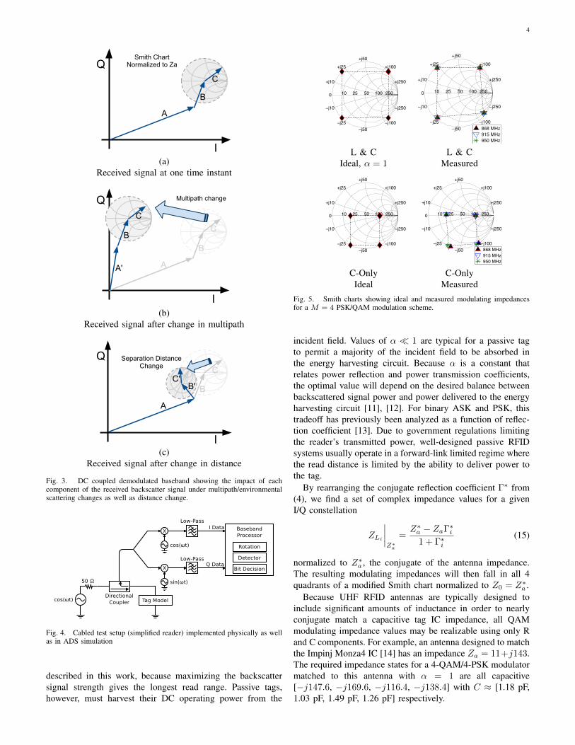
C to yield the desired data.The noise-free case is shown in Fig. 3(a). In this figure, a
modified Smith chart normalized to Z0 = Z
⇤a is positioned to
show the range of the load-dependent antenna-mode scatteringcontribution (~C) when only passive load impedances areconsidered.
Movement of nearby scatterers results in a change in theenvironmental multipath contribution. This translates the tag’stotal scattered field (
~
B+
~
C) within the I/Q plane as representedin Fig. 3(b). In contrast, as shown in Fig. 3(c), changing thetag-to-reader separation distance rotates total scattered field(
~
B +
~
C) due to the distance-dependent phase shift and scalesit in amplitude because of changing path loss. In the multipathcase, as well as the moving-tag case, there is a fixed phaserelationship between the structural scattering and antenna-mode scattering which is desirable because it preserves thetransmitted constellation.
This model has been confirmed experimentally throughmeasurements described below.
VI. QAM TAG MODULATOR DESIGN AND SIMULATION
Based on the observation from (7) that a careful choiceof modulating load impedance ZL can yield a scattered E-field component in any quadrant of the complex plane, aseries of modeling exercises were conducted to simulate apractical backscatter QAM modulator. Component choiceswere validated using Agilent ADS with the simplified readersystem model shown in Fig. 4.
Modulating impedance values can be chosen by first writingeach symbol of the desired I/Q constellation in the form
Si = xi + jyi (13)
where xi represents the in-phase component and yi representsthe quadrature component of the i-th symbol. In order toproduce impedance values realizable with passive components,all reflection coefficients are confined within a circle aboutthe conjugate match with magnitude 1. These reflectioncoefficients are then scaled by a constant 0 < ↵ 1.
�
⇤i = ↵ · Si
max |S| (14)
Values of ↵ closer to 1 reflect increasing amounts of theincident RF power back to the reader and thus result inhigher backscatter signal strength. This is the typical casefor a semi-passive (battery-assisted) tag, such as the one
4
4
,
$
%
&
6PLWK�&KDUW1RUPDOL]HG�WR�=D
(a)Received signal at one time instant
4
,
$
%
&%
&
$
0XOWLSDWK�FKDQJH
(b)Received signal after change in multipath
4
,
$
%
&
%&
6HSDUDWLRQ�'LVWDQFH&KDQJH
(c)Received signal after change in distance
Fig. 3. DC coupled demodulated baseband showing the impact of eachcomponent of the received backscatter signal under multipath/environmentalscattering changes as well as distance change.
Fig. 4. Cabled test setup (simplified reader) implemented physically as wellas in ADS simulation
described in this work, because maximizing the backscattersignal strength gives the longest read range. Passive tags,however, must harvest their DC operating power from the
0
+j10
−j10
+j25
−j25
+j50
−j50
+j100
−j100
+j250
−j250
10 25 50 100 250 0
+j10
!j10
+j25
!j25
+j50
!j50
+j100
!j100
+j250
!j250
10 25 50 100 250
868 MHz
915 MHz
950 MHz
L & C L & CIdeal, ↵ = 1 Measured
0
+j10
−j10
+j25
−j25
+j50
−j50
+j100
−j100
+j250
−j250
10 25 50 100 250 0
+j10
−j10
+j25
−j25
+j50
−j50
+j100
−j100
+j250
−j250
10 25 50 100 250
868 MHz 915 MHz 950 MHz
C-Only C-OnlyIdeal Measured
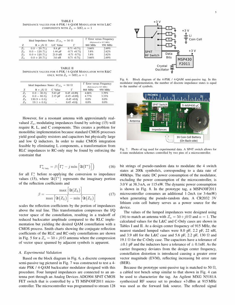
Fig. 5. Smith charts showing ideal and measured modulating impedancesfor a M = 4 PSK/QAM modulation scheme.
incident field. Values of ↵ ⌧ 1 are typical for a passive tagto permit a majority of the incident field to be absorbed inthe energy harvesting circuit. Because ↵ is a constant thatrelates power reflection and power transmission coefficients,the optimal value will depend on the desired balance betweenbackscattered signal power and power delivered to the energyharvesting circuit [11], [12]. For binary ASK and PSK, thistradeoff has previously been analyzed as a function of reflec-tion coefficient [13]. Due to government regulations limitingthe reader’s transmitted power, well-designed passive RFIDsystems usually operate in a forward-link limited regime wherethe read distance is limited by the ability to deliver power tothe tag.
By rearranging the conjugate reflection coefficient �⇤ from(4), we find a set of complex impedance values for a givenI/Q constellation
ZLi
����Z⇤
a
=
Z
⇤a � Za�
⇤i
1 + �
⇤i
(15)
normalized to Z
⇤a , the conjugate of the antenna impedance.
The resulting modulating impedances will then fall in all 4quadrants of a modified Smith chart normalized to Z0 = Z
⇤a .
Because UHF RFID antennas are typically designed toinclude significant amounts of inductance in order to nearlyconjugate match a capacitive tag IC impedance, all QAMmodulating impedance values may be realizable using only Rand C components. For example, an antenna designed to matchthe Impinj Monza4 IC [14] has an impedance Za = 11+j143.The required impedance states for a 4-QAM/4-PSK modulatormatched to this antenna with ↵ = 1 are all capacitive[�j147.6, �j169.6, �j116.4, �j138.4] with C ⇡ [1.18 pF,1.03 pF, 1.49 pF, 1.26 pF] respectively.
5
TABLE IIMPEDANCE VALUES FOR 4-PSK / 4-QAM MODULATOR WITH L&C
COMPONENTS WITH Za = 50⌦,↵ = 1
Ideal Impedance States: Z|Za = 50 ⌦� Error versus Frequency
(Referenced to 915 MHz)
Z R + jX ⌦ L/C Value � 860 MHz 950 MHzZ1 0.0 � 20.71j 8.4 pF 0.71 +0.71j 3.66% 2.69%Z2 0.0 � 120.71j 1.44 pF -0.71 +0.71j 3.8% 2.62%Z3 0.0 + 120.71j 21.0 nH -0.71 -0.71j 3.8% 2.62%Z4 0.0 + 20.71j 3.6 nH 0.71 -0.71j 3.66% 2.69%
TABLE IIIMPEDANCE VALUES FOR 4-PSK / 4-QAM MODULATOR WITH R&C
ONLY, WITH Za = 50⌦,↵ = 1
Ideal Impedance States: Z|Za = 50 ⌦� Error versus Frequency
(Referenced to 915 MHz)
Z R + jX ⌦ C Value � 868 MHz 950 MHzZ1 0.0 � 30.9j 5.63 pF 0.45 +0.89j 4.66% 3.39%Z2 0.0 � 80.9j 2.15 pF -0.45 +0.89j 4.77% 3.33%Z3 130.9 + 0.0j - -0.45 +0.0j 0.0% 0.0%Z4 19.1 + 0.0j - 0.45 +0.0j 0.0% 0.0%
However, for a resonant antenna with approximately real-valued Za, modulating impedances found by solving (15) willrequire R, L, and C components. This creates a problem formonolithic implementation because standard CMOS processesyield good quality resistors and capacitors but physically largeand low Q inductors. In order to make CMOS integrationfeasible by eliminating L components, a transformation fromRLC impedances to RC-only may be found by enforcing theconstraint that
�
⇤iC Only
= �
⇣�
⇤i � jmin
h=��
⇤�i⌘
(16)
for all �
⇤i before re-applying the conversion to impedance
values (15), where =��
⇤� represents the imaginary portionof the reflection coefficients and
� =
max
h=�ZL
�i
max
h=�ZL
�i�min
h=�ZL
�i (17)
scales the reflection coefficients by the portion of impedancesabove the real line. This transformation compresses the I/Qvector space of the constellation, resulting in a tradeoff ofreduced backscatter amplitude compared to the RLC imple-mentation but yielding the desired QAM constellation with aCMOS process. Smith charts showing the conjugate reflectioncoefficients of the RLC and RC-only constellations are shownin Fig. 5 for a Za = 50+j0⌦ antenna where the compressionof vector space spanned by adjacent symbols is apparent.
A. Experimental ValidationBased on the block diagram in Fig. 6, a discrete component
semi-passive tag pictured in Fig. 7 was constructed to test a 4-state PSK / 4-QAM backscatter modulator designed with thisprocedure. Four lumped impedances are connected to an an-tenna port through an Analog Devices ADG904 SP4T CMOSFET switch that is controlled by a TI MSP430F2011 micro-controller. The microcontroller was programmed to stream 128
Fig. 6. Block diagram of the 4-PSK / 4-QAM semi-passive tag. In thismodulator implementation, the number of discrete impedance states is equalto the number of symbols.
!"#$%!&'()*% $+,-!"#./%01%
23(4335%
.6%17'3%1488%95:4;<%=>3%95)?,@'A4B%
+CD4A53)4@%
Fig. 7. Photo of tag used for experimental data. A SP4T switch allows for4-state modulation schemes controlled by two pins of a microcontroller.
bit strings of pseudo-random data to modulate the 4 switchstates at 200k symbols/s, corresponding to a data rate of400kbps. The static DC power consumption of the modulator,excluding the power consumption of the microcontroller, is3.0 V at 38.3 nA, or 115 nW. The dynamic power consumptionis shown in Fig. 8. In the prototype tag, a MSP430F2011microcontroller consumes an additional 1-2mA (or 3-6mW)when generating the pseudo-random data. A CR2032 3Vlithium coin cell battery serves as a power source for thedevice.
The values of the lumped impedances were designed using(16) to match an antenna with Za = 50+j0⌦ and ↵ = 1. Thecalculated values for the L&C and C-Only cases are shown inTables I and II. At a design center frequency of 915 MHz, thenearest standard lumped values were 8.0 pF, 2.2 pF, 22 nH,and 3.9 nH for the L&C case and 5.6 pF, 2.2 pF, 130 ⌦ and19.1 ⌦ for the C-Only case. The capacitors have a tolerance of±0.1 pF and the inductors have a tolerance of ± 0.1nH. As thecarrier frequency deviates from the design center frequency,constellation distortion is introduced causing a greater errorvector magnitude (EVM), reflecting increasing bit error rate(BER).
Because the prototype semi-passive tag is matched to 50 ⌦,a cabled test bench setup similar to that shown in Fig. 4 canbe used to characterize the tag. An Agilent MXG N5181Asynthesized RF source set to produce +3 dBm at 915 MHzwas used as the forward link source. The reflected signal
6
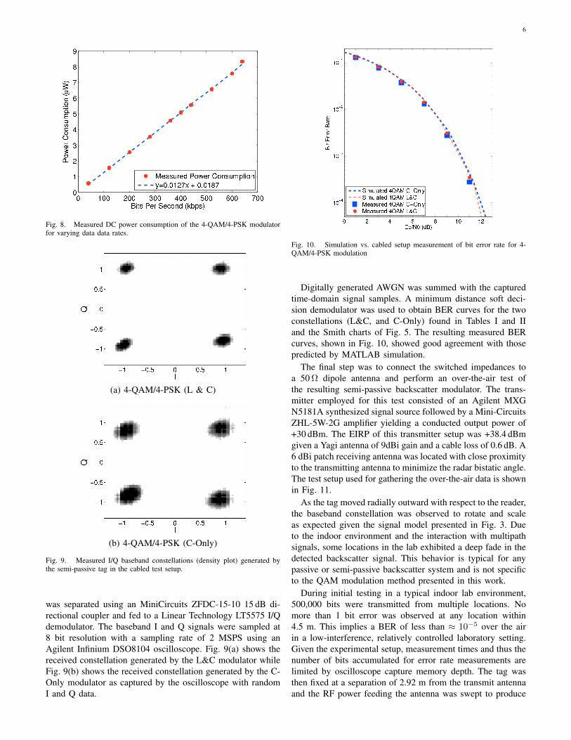
Fig. 8. Measured DC power consumption of the 4-QAM/4-PSK modulatorfor varying data data rates.
(a) 4-QAM/4-PSK (L & C)
(b) 4-QAM/4-PSK (C-Only)
Fig. 9. Measured I/Q baseband constellations (density plot) generated bythe semi-passive tag in the cabled test setup.
was separated using an MiniCircuits ZFDC-15-10 15 dB di-rectional coupler and fed to a Linear Technology LT5575 I/Qdemodulator. The baseband I and Q signals were sampled at8 bit resolution with a sampling rate of 2 MSPS using anAgilent Infinium DSO8104 oscilloscope. Fig. 9(a) shows thereceived constellation generated by the L&C modulator whileFig. 9(b) shows the received constellation generated by the C-Only modulator as captured by the oscilloscope with randomI and Q data.
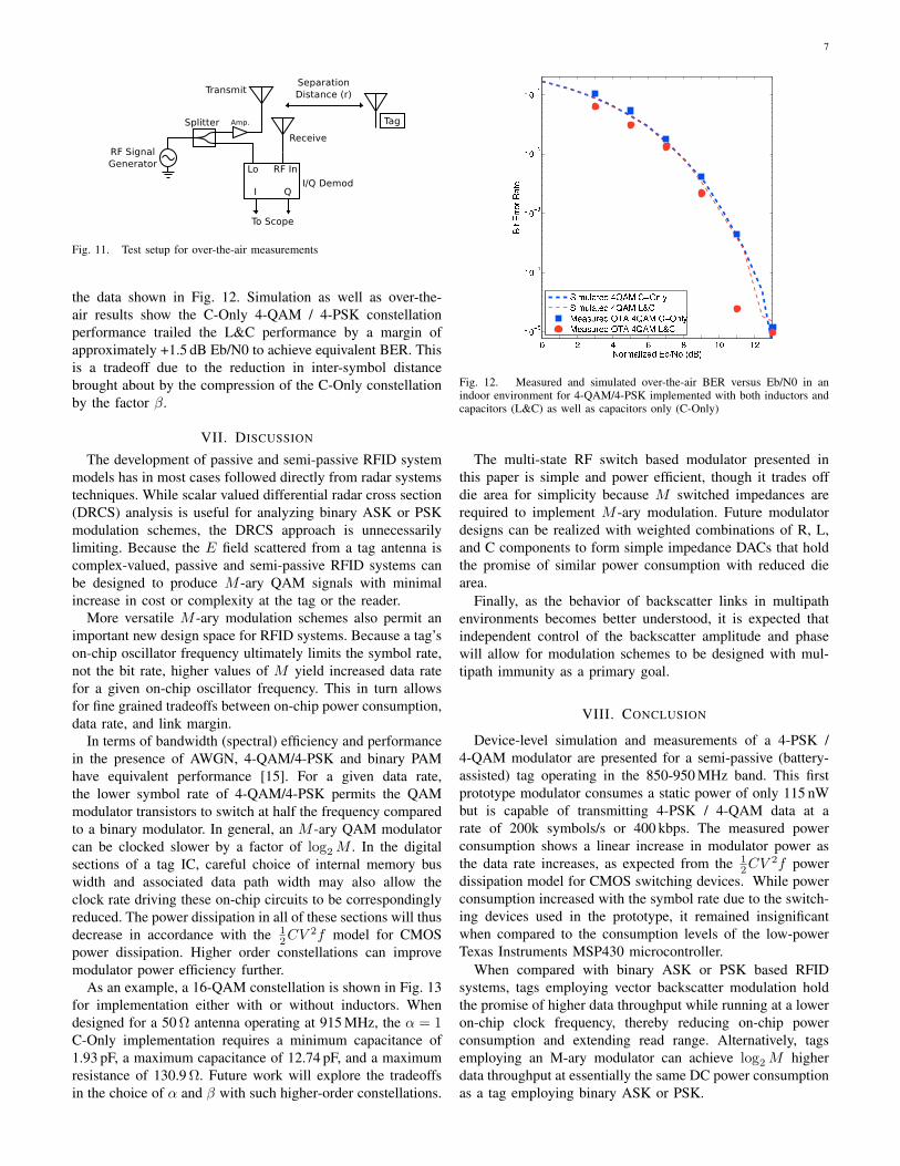
Fig. 10. Simulation vs. cabled setup measurement of bit error rate for 4-QAM/4-PSK modulation
Digitally generated AWGN was summed with the capturedtime-domain signal samples. A minimum distance soft deci-sion demodulator was used to obtain BER curves for the twoconstellations (L&C, and C-Only) found in Tables I and IIand the Smith charts of Fig. 5. The resulting measured BERcurves, shown in Fig. 10, showed good agreement with thosepredicted by MATLAB simulation.
The final step was to connect the switched impedances toa 50⌦ dipole antenna and perform an over-the-air test ofthe resulting semi-passive backscatter modulator. The trans-mitter employed for this test consisted of an Agilent MXGN5181A synthesized signal source followed by a Mini-CircuitsZHL-5W-2G amplifier yielding a conducted output power of+30 dBm. The EIRP of this transmitter setup was +38.4 dBmgiven a Yagi antenna of 9dBi gain and a cable loss of 0.6 dB. A6 dBi patch receiving antenna was located with close proximityto the transmitting antenna to minimize the radar bistatic angle.The test setup used for gathering the over-the-air data is shownin Fig. 11.
As the tag moved radially outward with respect to the reader,the baseband constellation was observed to rotate and scaleas expected given the signal model presented in Fig. 3. Dueto the indoor environment and the interaction with multipathsignals, some locations in the lab exhibited a deep fade in thedetected backscatter signal. This behavior is typical for anypassive or semi-passive backscatter system and is not specificto the QAM modulation method presented in this work.
During initial testing in a typical indoor lab environment,500,000 bits were transmitted from multiple locations. Nomore than 1 bit error was observed at any location within4.5 m. This implies a BER of less than ⇡ 10
�5 over the airin a low-interference, relatively controlled laboratory setting.Given the experimental setup, measurement times and thus thenumber of bits accumulated for error rate measurements arelimited by oscilloscope capture memory depth. The tag wasthen fixed at a separation of 2.92 m from the transmit antennaand the RF power feeding the antenna was swept to produce
7
Fig. 11. Test setup for over-the-air measurements
the data shown in Fig. 12. Simulation as well as over-the-air results show the C-Only 4-QAM / 4-PSK constellationperformance trailed the L&C performance by a margin ofapproximately +1.5 dB Eb/N0 to achieve equivalent BER. Thisis a tradeoff due to the reduction in inter-symbol distancebrought about by the compression of the C-Only constellationby the factor �.
VII. DISCUSSION
The development of passive and semi-passive RFID systemmodels has in most cases followed directly from radar systemstechniques. While scalar valued differential radar cross section(DRCS) analysis is useful for analyzing binary ASK or PSKmodulation schemes, the DRCS approach is unnecessarilylimiting. Because the E field scattered from a tag antenna iscomplex-valued, passive and semi-passive RFID systems canbe designed to produce M -ary QAM signals with minimalincrease in cost or complexity at the tag or the reader.
More versatile M -ary modulation schemes also permit animportant new design space for RFID systems. Because a tag’son-chip oscillator frequency ultimately limits the symbol rate,not the bit rate, higher values of M yield increased data ratefor a given on-chip oscillator frequency. This in turn allowsfor fine grained tradeoffs between on-chip power consumption,data rate, and link margin.
In terms of bandwidth (spectral) efficiency and performancein the presence of AWGN, 4-QAM/4-PSK and binary PAMhave equivalent performance [15]. For a given data rate,the lower symbol rate of 4-QAM/4-PSK permits the QAMmodulator transistors to switch at half the frequency comparedto a binary modulator. In general, an M -ary QAM modulatorcan be clocked slower by a factor of log2 M . In the digitalsections of a tag IC, careful choice of internal memory buswidth and associated data path width may also allow theclock rate driving these on-chip circuits to be correspondinglyreduced. The power dissipation in all of these sections will thusdecrease in accordance with the 1
2CV
2f model for CMOS
power dissipation. Higher order constellations can improvemodulator power efficiency further.
As an example, a 16-QAM constellation is shown in Fig. 13for implementation either with or without inductors. Whendesigned for a 50⌦ antenna operating at 915 MHz, the ↵ = 1
C-Only implementation requires a minimum capacitance of1.93 pF, a maximum capacitance of 12.74 pF, and a maximumresistance of 130.9⌦. Future work will explore the tradeoffsin the choice of ↵ and � with such higher-order constellations.
Fig. 12. Measured and simulated over-the-air BER versus Eb/N0 in anindoor environment for 4-QAM/4-PSK implemented with both inductors andcapacitors (L&C) as well as capacitors only (C-Only)
The multi-state RF switch based modulator presented inthis paper is simple and power efficient, though it trades offdie area for simplicity because M switched impedances arerequired to implement M -ary modulation. Future modulatordesigns can be realized with weighted combinations of R, L,and C components to form simple impedance DACs that holdthe promise of similar power consumption with reduced diearea.
Finally, as the behavior of backscatter links in multipathenvironments becomes better understood, it is expected thatindependent control of the backscatter amplitude and phasewill allow for modulation schemes to be designed with mul-tipath immunity as a primary goal.
VIII. CONCLUSION
Device-level simulation and measurements of a 4-PSK /4-QAM modulator are presented for a semi-passive (battery-assisted) tag operating in the 850-950 MHz band. This firstprototype modulator consumes a static power of only 115 nWbut is capable of transmitting 4-PSK / 4-QAM data at arate of 200k symbols/s or 400 kbps. The measured powerconsumption shows a linear increase in modulator power asthe data rate increases, as expected from the 1
2CV
2f power
dissipation model for CMOS switching devices. While powerconsumption increased with the symbol rate due to the switch-ing devices used in the prototype, it remained insignificantwhen compared to the consumption levels of the low-powerTexas Instruments MSP430 microcontroller.
When compared with binary ASK or PSK based RFIDsystems, tags employing vector backscatter modulation holdthe promise of higher data throughput while running at a loweron-chip clock frequency, thereby reducing on-chip powerconsumption and extending read range. Alternatively, tagsemploying an M-ary modulator can achieve log2 M higherdata throughput at essentially the same DC power consumptionas a tag employing binary ASK or PSK.

8
0
+j10
!j10
+j25
!j25
+j50
!j50
+j100
!j100
+j250
!j250
10 25 50 100 250 0
+j10
!j10
+j25
!j25
+j50
!j50
+j100
!j100
+j250
!j250
10 25 50 100 250
16-QAM L & C 16-QAM C-OnlyFig. 13. Ideal impedances for a M = 16 QAM modulator with Za = 50⌦and ↵ = 1, with and without inductors
Data in this paper was obtained using a discrete componentsemi-passive tag, but the methods are equally applicable tofully passive tags. Future work will expand upon this systemby implementing higher order constellations, improvementsto signal processing for multipath robustness, and finallyimplementing a fully passive, battery-free tag.
This material is based in part upon work supported by theNational Science Foundation under Grant Numbers CBET-0931924 and CMMI-0800858. Additional support has beenprovided by the Howard Hughes Medical Institute’s JaneliaFarm Research Campus.
REFERENCES
[1] EPC Global US, “Class 1 Generation 2 UHF RFID protocol for op-eration at 860MHz-960MHz, version 1.0.9,” Available online,http://www.epcglobalus.org/.
[2] S. Thomas and M. Reynolds, “QAM backscatter for passive UHF RFIDtags,” in 2010 IEEE International Conference on RFID, April 2010, pp.210 – 214.
[3] M. Winkler, T. Faseth, H. Arthaber, and G. Magerl, “An UHF RFID tagemulator for preceise emulation of the physical layer,” in 2010 EuropeanWireless Technology Conference (EuWIT), Sept. 2010, pp. 273–276.
[4] R. B. Green, “The general theory of antenna scattering,” Ph.D. disser-tation, The Ohio State University, United States – Ohio, 1963.
[5] C.-C. Yen, A. Gutierrez, D. Veeramani, and D. van der Weide, “Radarcross-section analysis of backscattering RFID tags,” IEEE Antennas andPropagation Letters, vol. 6, pp. 279–281, 2007.
[6] S. Shrestha, M. Balachandran, M. Agarwal, L.-H. Zou, andK. Varahramyan, “A method to measure radar cross section parametersof antennas,” IEEE Transactions on Antennas and Propagation, vol. 56,no. 11, pp. 3494 – 3500, Nov. 2008.
[7] A. Bletsas, A. G. Dimitriou, and J. Sahalos, “Improving backscatterradio tag efficiency,” IEEE Transactions on Microwave Theory andTechniques, vol. 58, no. 6, pp. 1502 – 1509, June 2010.
[8] P. Nikitin, K. Rao, and R. Martinez, “Differential RCS of RFID tag,”Electronics Letters, vol. 43, no. 8, pp. 431 – 432, April 2007.
[9] U. Karthaus and M. Fischer, “Fully integrated passive UHF RFIDtransponder IC with 16.7-µW minimum RF input power,” IEEE Journalof Solid-State Circuits, vol. 38, no. 10, pp. 1602–1608, October 2003.
[10] R. Hansen, “Relationships between antennas as scatterers and as radia-tors,” Proceedings of the IEEE, vol. 77, no. 5, pp. 659–662, May 1989.
[11] P. Nikitin, K. Rao, S. Lam, V. Pillai, R. Martinez, and H. Heinrich,“Power reflection coefficient analysis for complex impedances in RFIDtag design,” IEEE Transactions on Microwave Theory and Techniques,vol. 53, no. 9, pp. 2721–2725, Sept. 2005.
[12] K. Rao, P. Nikitin, and S. Lam, “Impedance matching concepts inRFID transponder design,” in Fourth IEEE Workshop on AutomaticIdentification Advanced Technologies, 2005., 17 – 18 2005, pp. 39 –42.
[13] J.-P. Curty, M. Declercq, C. Dehollain, and N. Joehl, Design andOptimization of passive UHF RFID Systems. Springer, 2007.
[14] Monza 4 tag chip datasheet. Impinj Inc. [Online]. Available: http://www.impinj.com/Documents/Tag Chips/Monza 4 Tag Chip Datasheet/
[15] J. G. Proakis and M. Salehi, Communication Systems Engineering,2nd ed. Upper Saddle River, New Jersey: Prentice-Hall, Inc., 2002.
Stewart J. Thomas (S’06) received the B.S. (cumlaude) and M.Eng. (magna cum laude) degrees inelectrical and computer engineering from the Uni-versity of Louisville, Louisville, KY in 2006 and2008, respectively. He is currently working towardshis Ph.D. degree in electrical and computer engineer-ing at Duke University. His research interests includewireless power transfer, backscatter communication,and innovations to UHF RFID technology.
Eric Wheeler received the B.S. (summa cum laude)and M.S. degrees in electrical and computer engi-neering from Duke University, Durham, NC in 2010and 2011 respectively. His research interests includelow-power signal processing and wireless networktechnologies. He is currently employed with GoogleInc. on the Android team.
Jochen Teizer is an Assistant Professor in theSchool of Civil and Environmental Engineering atthe Georgia Institute of Technology. He receivedthe Vor-Diplom (B.S.) and Dipl.-Ing. (M.S.) degreesfrom the University of Karlsruhe, Germany, and thePh.D. from the University of Texas, Austin in 2006.He is currently the founder and director of the Real-time Project Information and Decision Systems Lab-oratory (RAPIDS) at Georgia Tech. He has servedas an elected member of the Board of Directorsof the International Association on Automation and
Robotics in Construction (IAARC) since 2007. Dr. Teizer is currently servingas an Associate Specialty Editor of the American Society of Civil Engineering(ASCE) Journal of Construction Engineering and Management (JCEM).
Matthew S. Reynolds (S’01-M’02-SM’10) receivedthe S.B., M.Eng., and Ph.D. degrees from the Mas-sachusetts Institute of Technology in 1998, 1999,and 2003, respectively. He is currently the Nor-tel Networks Assistant Professor of Electrical andComputer Engineering at Duke University. He is acofounder of the RFID systems firm ThingMagicInc. and the demand-side energy conservation tech-nology firm Zensi. His research interests include thephysics of sensors and actuators, RFID, and signalprocessing. He is a member of the Signal Processing
and Communications Group and the Computer Engineering Group at Duke,as well as the IEEE Microwave Theory and Techniques Society.