Embed Size (px)
Citation preview
1
Quadrocopter projectTU/e - Embedded Visual Control - 5HC99 - Group 2 - Summer 2012
Okke Hendriks0758134
Koen Hausmans0661622
Richard van Berkel0753933
Douwe van Nijnatten0732553
Abstract—This document describes the progress and designdecisions made for the quadrocopter project in the embeddedvisual control course. A Pandaboard is used to run the localcontrol. The local control allows the quadrocopter to stabilizein mid air as well as to process directional commands. Onecan communicate with the board via wifi. For the visualaspect of the project, a LIDAR system has been designed.Further research is required to determine the feasibility ofthe implementation.
Index Terms—Embedded, visual, control, PID, DCM,LIDAR
INTRODUCTION
For the Embedded Visual Control (EVC) course we wereasked to design and build a quadrocopter. The project iscomprised out of four main goals. The first goal is to buildthe quadrocopter itself. Secondly to design and implementa local control such that the vehicle can fly in a stablemanner. Stable is defined in this context as not crashingand preferably hovering in more or less the same spot in thex, y, z plane. Thirdly a unit should be implemented whichallows the quadrocopter to “discover” its environment. Thisis implemented using a LIDAR system of our own design.Fourth and last, the vehicle should use the knowledge of itssurroundings to navigate its way through a room or corridor.During the course of the project the goals have been revisedsuch that the project only covers the first two and partiallythe third due to time limits.
The remainder of the report is organised as follows. First,the design choices made during the construction of the quad-rocopter are explained. The second chapter is devoted to theembedded part of the project. The hardware architectureand the power and motor schematics are introduced andexplained. The visual aspect of the project is treated in thethird chapter while the local control software is treated inthe fourth. In the fifth chapter the conclusions are drawnwhile the sixth concludes the report with future researchtopics.
I. DESIGN CHOICES
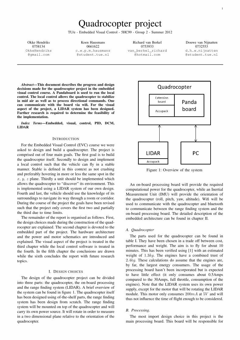
The design of the quadrocopter project can be dividedinto three parts: the quadrocopter, the on-board processingand the range finding system (LIDAR). A brief overview ofthe system can be found in figure 1. The quadrocopter itselfhas been designed using of-the-shelf parts, the range findingsystem has been design from scratch. The range findingsystem will be mounted on top of the quadrocopter and willcarry its own power source. It will rotate in order to measurein a two dimensional plane relative to the orientation of thequadrocopter.
Figure 1: Overview of the system
An on-board processing board will provide the requiredcomputational power for the quadrocopter, while an InertialMeasurement Unit (IMU) will provide the orientation ofthe quadrocopter (roll, pitch, yaw, altitude). Wifi will beused to communicate with the quadrocopter and bluetoothto communicate between the range finding system and theon-board processing board. The detailed description of theembedded architecture can be found in chapter II.
A. Quadrocopter
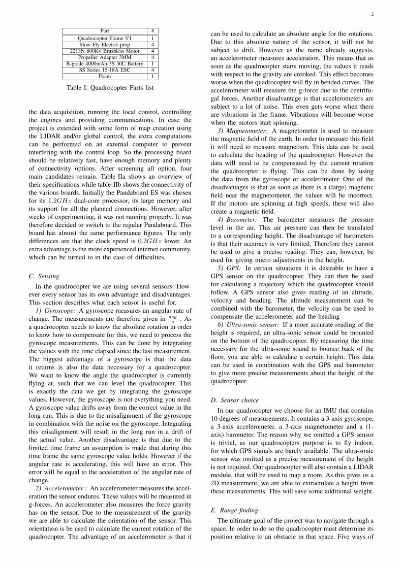
The parts used for the quadrocopter can be found intable I. They have been chosen in a trade off between cost,performance and weight. The aim is to fly for about 10minutes. This has been verified using [1] with an estimatedweight of 1.3kg. The engines have a combined trust of2.4kg. These calculations do assume that the engines are,by far, the largest energy consumers. The usage of theprocessing board hasn’t been incorporated but is expectedto have little effect (it only consumes about 0.5Ampscompared to the 30Amps, full throttle, consumption of theengines). Note that the LIDAR system uses its own powersupply, except for the motor that will be rotating the LIDARmodule. This motor only consumes 200mA at 5V and willthus not influence the time of flight enough to be considered.
B. Processing.
The most import design choice in this project is themain processing board. This board will be responsible for
2
Part #Quadrocopter Frame V1 1Slow Fly Electric prop 4
2213N 800Kv Brushless Motor 4Propeller Adapter 3MM 4
B-grade 4000mAh 3S 30C Battery 1SS Series 15-18A ESC 4
Foam 1
Table I: Quadrocopter Parts list
the data acquisition, running the local control, controllingthe engines and providing communications. In case theproject is extended with some form of map creation usingthe LIDAR and/or global control, the extra computationscan be performed on an external computer to preventinterfering with the control loop. So the processing boardshould be relatively fast, have enough memory and plentyof connectivity options. After screening all option, fourmain candidates remain. Table IIa shows an overview oftheir specifications while table IIb shows the connectivity ofthe various boards. Initially the Pandaboard ES was chosenfor its 1.2GHz dual-core processor, its large memory andits support for all the planned connections. However, afterweeks of experimenting, it was not running properly. It wastherefore decided to switch to the regular Pandaboard. Thisboard has almost the same performance figures. The onlydifferences are that the clock speed is 0.2GHz lower. Anextra advantage is the more experienced internet community,which can be turned to in the case of difficulties.
C. Sensing
In the quadrocopter we are using several sensors. How-ever every sensor has its own advantage and disadvantages.This section describes what each sensor is useful for.
1) Gyroscope: A gyroscope measures an angular rate ofchange. The measurements are therefore given in deg
s . Asa quadrocopter needs to know the absolute rotation in orderto know how to compensate for this, we need to process thegyroscope measurements. This can be done by integratingthe values with the time elapsed since the last measurement.The biggest advantage of a gyroscope is that the datait returns is also the data necessary for a quadrocopter.We want to know the angle the quadrocopter is currentlyflying at, such that we can level the quadrocopter. Thisis exactly the data we get by integrating the gyroscopevalues. However, the gyroscope is not everything you need.A gyroscope value drifts away from the correct value in thelong run. This is due to the misalignment of the gyroscopein combination with the noise on the gyroscope. Integratingthis misalignment will result in the long run in a drift ofthe actual value. Another disadvantage is that due to thelimited time frame an assumption is made that during thistime frame the same gyroscope value holds. However if theangular rate is accelerating, this will have an error. Thiserror will be equal to the acceleration of the angular rate ofchange.
2) Accelerometer : An accelerometer measures the accel-eration the sensor endures. These values will be measured ing-forces. An accelerometer also measures the force gravityhas on the sensor. Due to the measurement of the gravitywe are able to calculate the orientation of the sensor. Thisorientation is be used to calculate the current rotation of thequadrocopter. The advantage of an accelerometer is that it
can be used to calculate an absolute angle for the rotations.Due to this absolute nature of the sensor, it will not besubject to drift. However as the name already suggests,an accelerometer measures acceleration. This means that assoon as the quadrocopter starts moving, the values it readswith respect to the gravity are crooked. This effect becomesworse when the quadrocopter will fly in bended curves. Theaccelerometer will measure the g-force due to the centrifu-gal forces. Another disadvantage is that accelerometers aresubject to a lot of noise. This even gets worse when thereare vibrations in the frame. Vibrations will become worsewhen the motors start spinning.
3) Magnetometer: A magnetometer is used to measurethe magnetic field of the earth. In order to measure this fieldit will need to measure magnetism. This data can be usedto calculate the heading of the quadrocopter. However thedata will need to be compensated by the current rotationthe quadrocopter is flying. This can be done by usingthe data from the gyroscope or accelerometer. One of thedisadvantages is that as soon as there is a (large) magneticfield near the magnetometer, the values will be incorrect.If the motors are spinning at high speeds, these will alsocreate a magnetic field.
4) Barometer: The barometer measures the pressurelevel in the air. This air pressure can then be translatedto a corresponding height. The disadvantage of barometersis that their accuracy is very limited. Therefore they cannotbe used to give a precise reading. They can, however, beused for giving micro adjustments in the height.
5) GPS: In certain situations it is desirable to have aGPS sensor on the quadrocopter. They can then be usedfor calculating a trajectory which the quadrocopter shouldfollow. A GPS sensor also gives reading of an altitude,velocity and heading. The altitude measurement can becombined with the barometer, the velocity can be used tocompensate the accelerometer and the heading
6) Ultra-sonic sensor: If a more accurate reading of theheight is required, an ultra-sonic sensor could be mountedon the bottom of the quadrocopter. By measuring the timenecessary for the ultra-sonic sound to bounce back of thefloor, you are able to calculate a certain height. This datacan be used in combination with the GPS and barometerto give more precise measurements about the height of thequadrocopter.
D. Sensor choice
In our quadrocopter we choose for an IMU that contains10 degrees of measurements. It contains a 3-axis gyroscope,a 3-axis accelerometer, a 3-axis magnetometer and a (1-axis) barometer. The reason why we omitted a GPS sensoris trivial, as our quadrocopters purpose is to fly indoor,for which GPS signals are barely available. The ultra-sonicsensor was omitted as a precise measurement of the heightis not required. Our quadrocopter will also contain a LIDARmodule, that will be used to map a room. As this gives us a2D measurement, we are able to extractulate a height fromthese measurements. This will save some additional weight.
E. Range finding
The ultimate goal of the project was to navigate through aspace. In order to do so the quadrocopter must determine itsposition relative to an obstacle in that space. Five ways of
3
Processor Core Speed Graphics support Memory Weight size CostPandaboard OMAP4430 Dual-core ARM Cortex-A9 1.0[GHz] PowerVR 1GB DDR2 74g 4.45’x4.00’ C 143,55
Pandaboard ES OMAP4460 Dual-core ARM Cortex-A9 1.2 [GHz] PowerVR 1GB DDR2 81.5g 4.50’x4.00’ C 152,63BeagleBoard OMAP3530 ARM Cortex-A8 0.6[GHz] DSP 128 MB DDR2 TBW 3.00’x3.10’ C 103,13
BeagleBoard -xM DM3730CBP ARM Cortex-A8 1.0[GHz] DSP 512 MB DDR2 TBW 3.35’x4.35’ C 122,93
(a) Processor specifications
WIFI Bluetooth Ethernet USB JTAG UART GPIO (micro) SD-slot Camera support
Pandaboard ! ! ! ! ! ! ! ! !
Pandaboard ES ! ! ! ! ! ! ! ! !
BeagleBoard # # # ! ! ! ! ! #
BeagleBoard -xM # # ! ! ! ! ! ! !
(b) Processor connections table
Table II: Comparing processing boards
detection have been considered: Touch, ultrasound, infra-red, LIDAR and vision using a camera. Touch has beendiscarded because of the risk to damage the quadrocopterand/or environment. The biggest downside of ultrasoundand infra-red is that their accuracy is very bad at longerdistance and therefore have a very limited range. Sensitivityto respectively temperature, pressure or other light/soundsources are other disadvantages. LIDAR is accurate buthas difficulties detecting reflecting objects (windows/metalplates) and of the shelf solutions are expensive. A camera re-quires excessive computational power, advanced algorithmsand is sensitive to changes in light. Overall the LIDAR isthe best option if a way is found to keep the cost low.Therefore, it will be designed from scratch.
The design process of the LIDAR and the LIDAR specificdesign choices can be found in chapter III.
II. EMBEDDED
The quadrocopter is equipped with on-board embeddedintelligence. As described in section I-B, the Pandaboard isused as the base for the quadrocopter’s intelligence. How-ever, the Pandaboard does not contain any sensors (such asaccelerometers), so called PWM outputs for controlling themotors, power supply etc. To meet all those requirements,an extension had to be realized on top of the Pandaboard.
A. Pandaboard extension
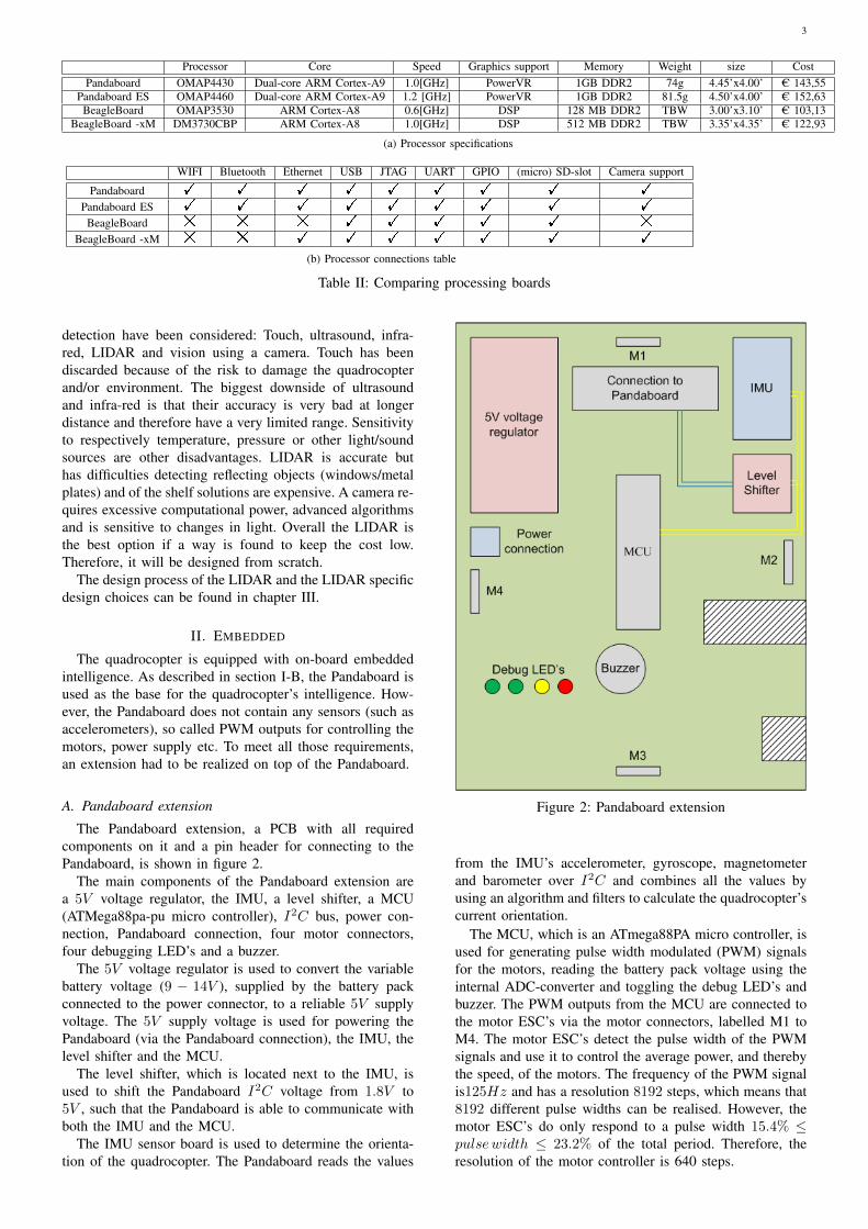
The Pandaboard extension, a PCB with all requiredcomponents on it and a pin header for connecting to thePandaboard, is shown in figure 2.
The main components of the Pandaboard extension area 5V voltage regulator, the IMU, a level shifter, a MCU(ATMega88pa-pu micro controller), I2C bus, power con-nection, Pandaboard connection, four motor connectors,four debugging LED’s and a buzzer.
The 5V voltage regulator is used to convert the variablebattery voltage (9 − 14V ), supplied by the battery packconnected to the power connector, to a reliable 5V supplyvoltage. The 5V supply voltage is used for powering thePandaboard (via the Pandaboard connection), the IMU, thelevel shifter and the MCU.
The level shifter, which is located next to the IMU, isused to shift the Pandaboard I2C voltage from 1.8V to5V , such that the Pandaboard is able to communicate withboth the IMU and the MCU.
The IMU sensor board is used to determine the orienta-tion of the quadrocopter. The Pandaboard reads the values
Figure 2: Pandaboard extension
from the IMU’s accelerometer, gyroscope, magnetometerand barometer over I2C and combines all the values byusing an algorithm and filters to calculate the quadrocopter’scurrent orientation.
The MCU, which is an ATmega88PA micro controller, isused for generating pulse width modulated (PWM) signalsfor the motors, reading the battery pack voltage using theinternal ADC-converter and toggling the debug LED’s andbuzzer. The PWM outputs from the MCU are connected tothe motor ESC’s via the motor connectors, labelled M1 toM4. The motor ESC’s detect the pulse width of the PWMsignals and use it to control the average power, and therebythe speed, of the motors. The frequency of the PWM signalis125Hz and has a resolution 8192 steps, which means that8192 different pulse widths can be realised. However, themotor ESC’s do only respond to a pulse width 15.4% ≤pulsewidth ≤ 23.2% of the total period. Therefore, theresolution of the motor controller is 640 steps.
4
B. Software architecture
The software of the quadrocopter consists out of twoparts, the software running on the Pandaboard and thesoftware running on the MCU at the extension board. Thesoftware for the Pandaboard is written in C + + while thesoftware for the MCU is written in C.
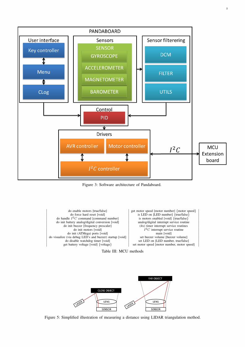
1) Pandaboard: The software of the Pandaboard is buildup from classes that are interacting with each other. In figure3 a schematic representation of the software structure isprovided. Five main blocks can be seen, User interface,Sensors, Sensor filtering, Control and Drivers.
The User interface is provided through an SSH con-nection to an users PC. The provided menu knows twotypes of items, displays and edit fields. The displays can beconfigured such, by a programmer, that it displays a certainvariable in the program. The edit fields can be configuredsuch that a user can selected a field, using the arrow-keys,and alter the connected variable by pressing the + and -keys.
The Sensors consist out of four classes that inherent the’Sensor’ class. The classes provide all functionality thatis needed to initialize, calibrate and extract measurementsfrom the different sensors. These classes are instantiated andused by the Sensor filtering.
The Sensor filtering combines the raw data from thedifferent sensors to the current roll, pitch and yaw andalso applies DCM filtering on them. The DCM filtering isdescribed in detail in section IV-C.
The Control section contains the PID class, it takes inputfrom the user interface in the form of a wanted roll, pitchand yaw values. In the future these values should come fromthe global control. It also takes the current roll, pitch andyaw from the Sensor filtering and produced a percentagefrom 0 − 100% for each motor, again this is described indetail in section IV-C.
The drivers form a two level control. Both the AVRcontroller and the Motor controller use the I2C controllerto communicate with the MCU on the extension board. TheAVR controller is used for general purpose communicationwith the MCU such as toggling LEDs, retrieving batteryvoltage, etc. The Motor controller takes the motor percent-age from the PID control, calculates the timer values forthe MCU and communicates them to the MCU.
2) MCU: For the MCU no class structure is used,there are a number of functions and interrupt routines thatprovide the desired functionality. In table III, an overviewof the MCU’s software methods is given. The MCU isprogrammed such that it listens to the I2C bus for I2Ccommands. Each time the MCU receives an I2C command,an interrupt will occur and the I2C interrupt service routineis executed. The I2C interrupt routine analyses the receivedmessage and executes one of the do-, is-, get- or set-methods, depending on the message, for example set motorspeed [1, 80]. Next to the I2C interrupt routine, there arefour timer interrupt routines with a higher priority which areresponsible for generating the actual PWM signals whichare always active when MCU is switched on. Furthermore,there is one interrupt service routine that measures thebattery voltage, which can be activated on request.
III. VISUAL
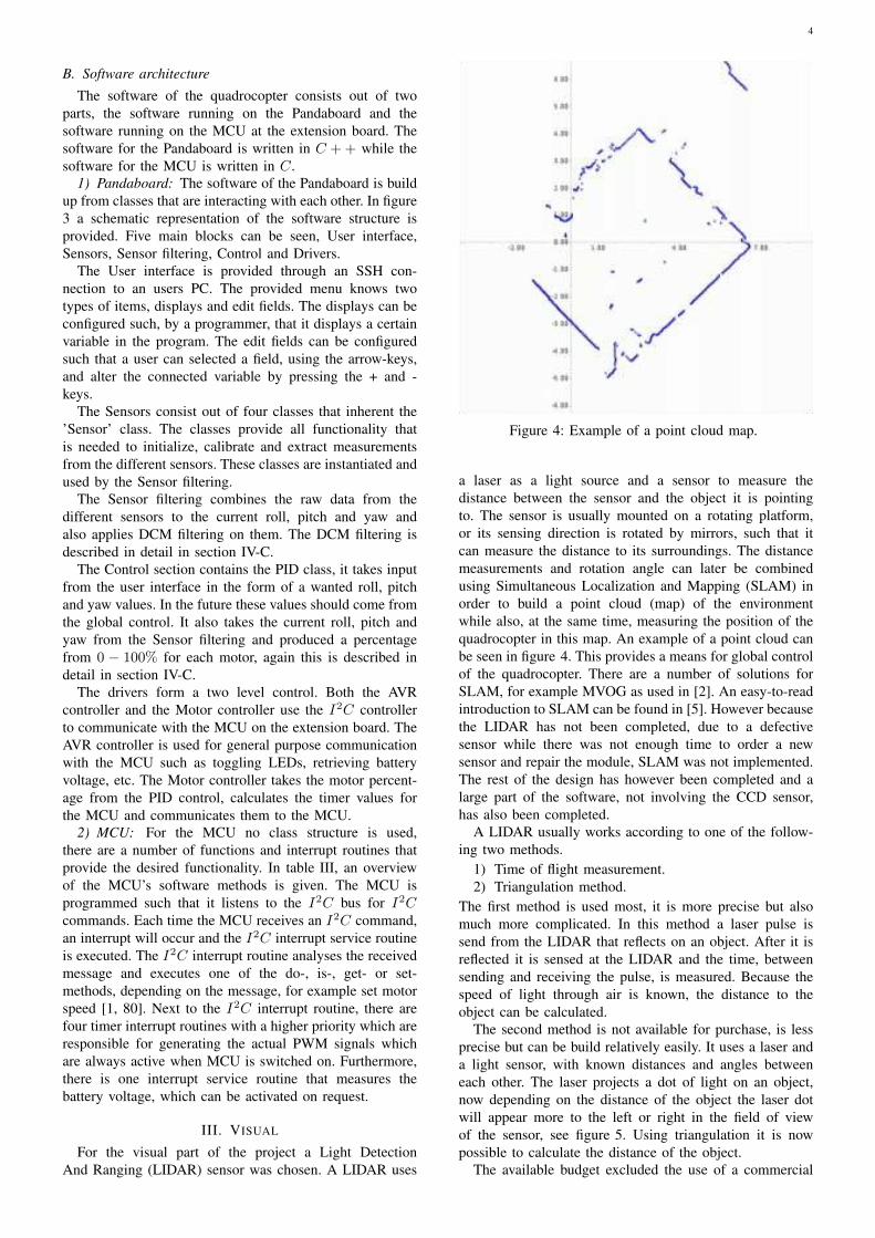
For the visual part of the project a Light DetectionAnd Ranging (LIDAR) sensor was chosen. A LIDAR uses
Figure 4: Example of a point cloud map.
a laser as a light source and a sensor to measure thedistance between the sensor and the object it is pointingto. The sensor is usually mounted on a rotating platform,or its sensing direction is rotated by mirrors, such that itcan measure the distance to its surroundings. The distancemeasurements and rotation angle can later be combinedusing Simultaneous Localization and Mapping (SLAM) inorder to build a point cloud (map) of the environmentwhile also, at the same time, measuring the position of thequadrocopter in this map. An example of a point cloud canbe seen in figure 4. This provides a means for global controlof the quadrocopter. There are a number of solutions forSLAM, for example MVOG as used in [2]. An easy-to-readintroduction to SLAM can be found in [5]. However becausethe LIDAR has not been completed, due to a defectivesensor while there was not enough time to order a newsensor and repair the module, SLAM was not implemented.The rest of the design has however been completed and alarge part of the software, not involving the CCD sensor,has also been completed.
A LIDAR usually works according to one of the follow-ing two methods.
1) Time of flight measurement.2) Triangulation method.
The first method is used most, it is more precise but alsomuch more complicated. In this method a laser pulse issend from the LIDAR that reflects on an object. After it isreflected it is sensed at the LIDAR and the time, betweensending and receiving the pulse, is measured. Because thespeed of light through air is known, the distance to theobject can be calculated.
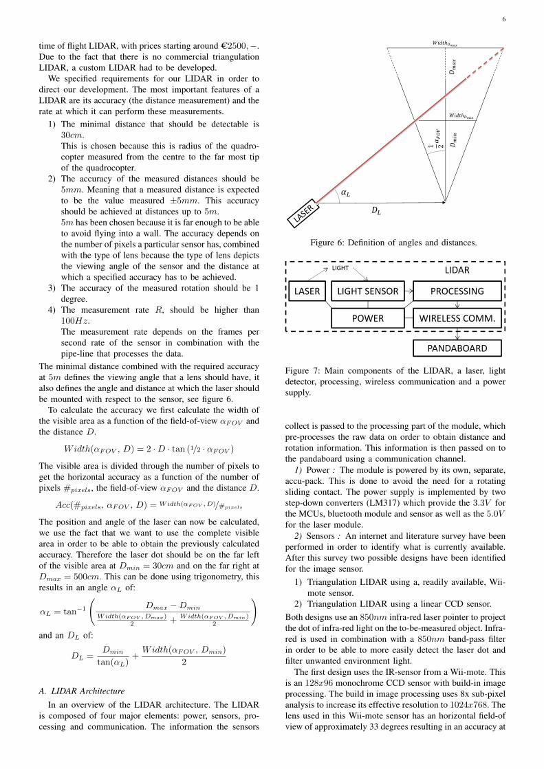
The second method is not available for purchase, is lessprecise but can be build relatively easily. It uses a laser anda light sensor, with known distances and angles betweeneach other. The laser projects a dot of light on an object,now depending on the distance of the object the laser dotwill appear more to the left or right in the field of viewof the sensor, see figure 5. Using triangulation it is nowpossible to calculate the distance of the object.
The available budget excluded the use of a commercial
5
Figure 3: Software architecture of Pandaboard.
do enable motors [true/false] get motor speed [motor number] {motor speed}do force hard reset [void] is LED on [LED number] {true/false}
do handle I2C command [command number] is motors enabled [void] {true/false}do init battery analog/digital conversion [void] analog/digital interrupt service routine
do init buzzer [frequency prescaler] (4x) timer interrupt service routinesdo init motors [void] I2C interrupt service routine
do init (ATMega) ports [void] main [void]do visualize (via debug LED’s and buzzer) startup [void] set buzzer volume [buzzer volume]
do disable watchdog timer [void] set LED on [LED number, true/false]get battery voltage [void] {voltage} set motor speed [motor number, motor speed]
Table III: MCU methods
Figure 5: Simplified illustration of measuring a distance using LIDAR triangulation method.
6
time of flight LIDAR, with prices starting around C2500,−.Due to the fact that there is no commercial triangulationLIDAR, a custom LIDAR had to be developed.
We specified requirements for our LIDAR in order todirect our development. The most important features of aLIDAR are its accuracy (the distance measurement) and therate at which it can perform these measurements.
1) The minimal distance that should be detectable is30cm.This is chosen because this is radius of the quadro-copter measured from the centre to the far most tipof the quadrocopter.
2) The accuracy of the measured distances should be5mm. Meaning that a measured distance is expectedto be the value measured ±5mm. This accuracyshould be achieved at distances up to 5m.5m has been chosen because it is far enough to be ableto avoid flying into a wall. The accuracy depends onthe number of pixels a particular sensor has, combinedwith the type of lens because the type of lens depictsthe viewing angle of the sensor and the distance atwhich a specified accuracy has to be achieved.
3) The accuracy of the measured rotation should be 1degree.
4) The measurement rate R, should be higher than100Hz.The measurement rate depends on the frames persecond rate of the sensor in combination with thepipe-line that processes the data.
The minimal distance combined with the required accuracyat 5m defines the viewing angle that a lens should have, italso defines the angle and distance at which the laser shouldbe mounted with respect to the sensor, see figure 6.
To calculate the accuracy we first calculate the width ofthe visible area as a function of the field-of-view αFOV andthe distance D.
Width(αFOV , D) = 2 ·D · tan (1/2 · αFOV )
The visible area is divided through the number of pixels toget the horizontal accuracy as a function of the number ofpixels #pixels, the field-of-view αFOV and the distance D.
Acc(#pixels, αFOV , D) = Width(αFOV , D)/#pixels
The position and angle of the laser can now be calculated,we use the fact that we want to use the complete visiblearea in order to be able to obtain the previously calculatedaccuracy. Therefore the laser dot should be on the far leftof the visible area at Dmin = 30cm and on the far right atDmax = 500cm. This can be done using trigonometry, thisresults in an angle αL of:
αL = tan−1
(Dmax −Dmin
Width(αFOV , Dmax)2 + Width(αFOV , Dmin)
2
)and an DL of:
DL =Dmin
tan(αL)+Width(αFOV , Dmin)
2
A. LIDAR Architecture
In an overview of the LIDAR architecture. The LIDARis composed of four major elements: power, sensors, pro-cessing and communication. The information the sensors
Figure 6: Definition of angles and distances.
���������� �� �����
��������� �������
��������
�����
�����
�����
Figure 7: Main components of the LIDAR, a laser, lightdetector, processing, wireless communication and a powersupply.
collect is passed to the processing part of the module, whichpre-processes the raw data on order to obtain distance androtation information. This information is then passed on tothe pandaboard using a communication channel.
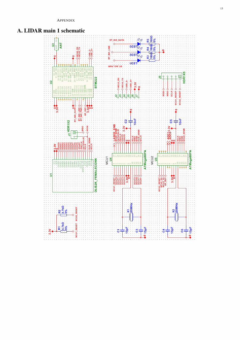
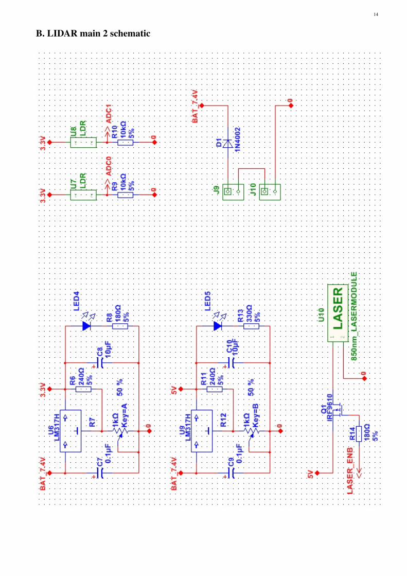
1) Power : The module is powered by its own, separate,accu-pack. This is done to avoid the need for a rotatingsliding contact. The power supply is implemented by twostep-down converters (LM317) which provide the 3.3V forthe MCUs, bluetooth module and sensor as well as the 5.0Vfor the laser module.
2) Sensors : An internet and literature survey have beenperformed in order to identify what is currently available.After this survey two possible designs have been identifiedfor the image sensor.
1) Triangulation LIDAR using a, readily available, Wii-mote sensor.
2) Triangulation LIDAR using a linear CCD sensor.Both designs use an 850nm infra-red laser pointer to projectthe dot of infra-red light on the to-be-measured object. Infra-red is used in combination with a 850nm band-pass filterin order to be able to more easily detect the laser dot andfilter unwanted environment light.
The first design uses the IR-sensor from a Wii-mote. Thisis an 128x96 monochrome CCD sensor with build-in imageprocessing. The build in image processing uses 8x sub-pixelanalysis to increase its effective resolution to 1024x768. Thelens used in this Wii-mote sensor has an horizontal field-ofview of approximately 33 degrees resulting in an accuracy at
7
Dmax = 500cm of Acc(1024, 33, 500) = 0.289cm whichis indeed smaller than the required 0.5cm. Experiments haveshown that this sensor can be operated at refresh rate ofabout 200Hz when operated in I2C mode. This is not thestandard mode it is operated in, and thus it is necessaryto dismantle a Wii-mote and communicate with the sensordirectly. Instructions on how to communicate with the IR-sensor directly can be found online, see [4].
Because of the simplicity and availability of the Wii-motecompared to the DLIS-2K the decision was made to go forthe first design. We succeeded in dismantling the Wii-mote,retrieving the IR-sensor and read detected IR-spots usingI2C in an experimental breadboard setting. However thesensitivity of the sensor at the used 850nm laser IR-lightproofed to be too low to be useful. The maximal range atwhich laser dots were detected was about 20cm. The optionto buy a laser pointer with another bandwidth (950nm)was considered but it proofed to be impossible to get alaser module, and filter, for a price that fitted our budget.Therefore a switch to the second design was made.
The second design is inspired by [6]. In this paper theDLIS-2K linear CCD sensor is used. After an evaluationof linear sensors the only affordable and available sensorsproofed to be either the ELIS-2K or the DLIS-2K fromPanavision. These sensors have about the same properties,but the ELIS-2K has an analogue output and all controlsignals have to be generated externally. The DLIS-2Khowever, has an internal controller and ADC converter thatgenerates all control signals and the pixel data is outputteddigitally. Because an MCU as processor will be used, seethe section ’Processing’ below, and this processor is alreadyat 100% utilization the DLIS-2K has been used. Thereforethe MCU will only need to provide a clock signal and startsignal to the sensor. The DLIS-2K sensor has an horizontalresolution of 2081 pixels. Together with a lens (BL-D/N-16-350-950nm-1MP) from Stock Optics with a field-of-view of 23.3 degrees we can calculate the accuracy atDmax = 500cm Acc(2081, 23.3, 500) = 0.099cm. Whichindeed conforms to the requirement of 0.5cm. The framerate is, in our implementation, limited by the processing.
In order to detect the angle of the LIDAR module thefollowing two methods have been considered.
1) Rotary encoder on axle of motor rotating the LIDARmodule.
2) LEDs on the quadrocopter, LDRs on the LIDARmodule.
Option one has not been chosen because it implied thedevelopment and implementation of another controller andbecause it was an more expensive option. Therefore methodtwo has been implemented. There are two LDRs on theLIDAR module. LEDS are placed in such manner on thequadrocopter that on of the LDRs only gets a signal atrotation αLIDAR = 0. Assuming the motor speed, ofthe motor rotating the module, is perfectly constant thissingle LED is enough to determine the angle of the LIDARmodule. This can be done by measuring the time betweentwo stimulations of the LDR and then interpolating theangle such that we derive the angle of the module at acertain moment in time. The second LDR can be used toincrease accuracy when there is a slight variance in motorspeed. An array of LEDS should be placed in a circlebelow this second LDR. The first LDR is than only used todetermine the start position of zero degrees and the second
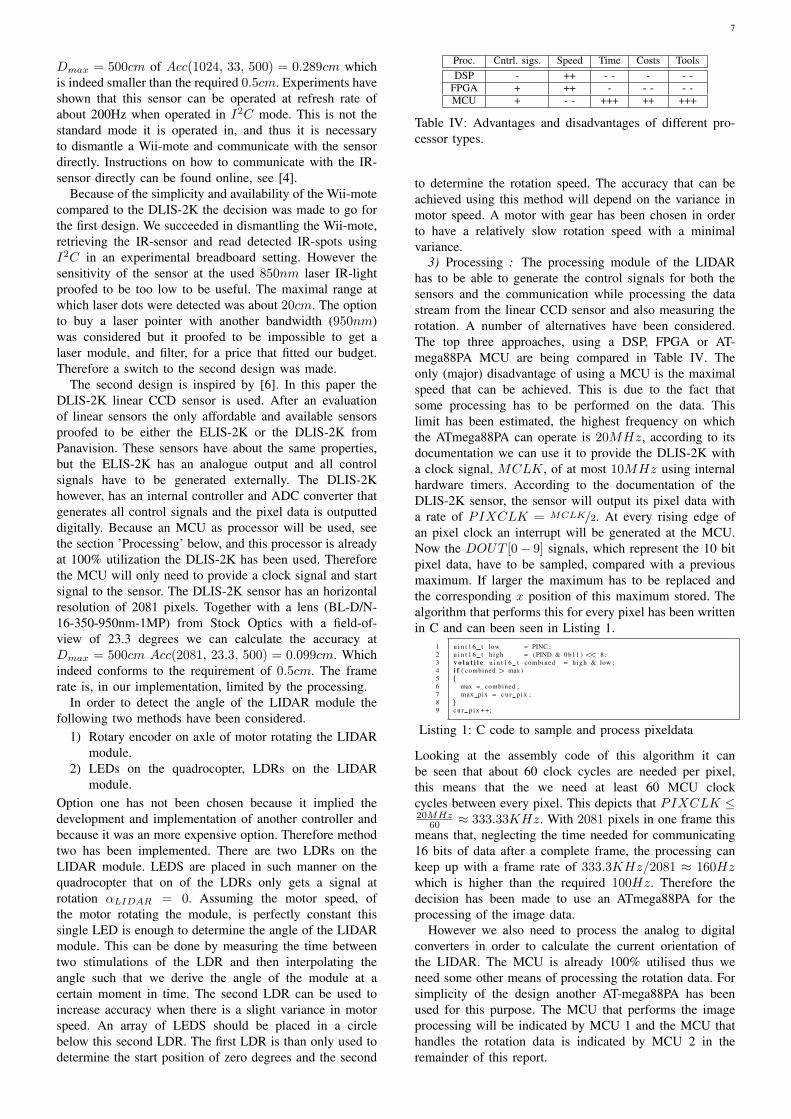
Proc. Cntrl. sigs. Speed Time Costs ToolsDSP - ++ - - - - -
FPGA + ++ - - - - -MCU + - - +++ ++ +++
Table IV: Advantages and disadvantages of different pro-cessor types.
to determine the rotation speed. The accuracy that can beachieved using this method will depend on the variance inmotor speed. A motor with gear has been chosen in orderto have a relatively slow rotation speed with a minimalvariance.
3) Processing : The processing module of the LIDARhas to be able to generate the control signals for both thesensors and the communication while processing the datastream from the linear CCD sensor and also measuring therotation. A number of alternatives have been considered.The top three approaches, using a DSP, FPGA or AT-mega88PA MCU are being compared in Table IV. Theonly (major) disadvantage of using a MCU is the maximalspeed that can be achieved. This is due to the fact thatsome processing has to be performed on the data. Thislimit has been estimated, the highest frequency on whichthe ATmega88PA can operate is 20MHz, according to itsdocumentation we can use it to provide the DLIS-2K witha clock signal, MCLK, of at most 10MHz using internalhardware timers. According to the documentation of theDLIS-2K sensor, the sensor will output its pixel data witha rate of PIXCLK = MCLK/2. At every rising edge ofan pixel clock an interrupt will be generated at the MCU.Now the DOUT [0 − 9] signals, which represent the 10 bitpixel data, have to be sampled, compared with a previousmaximum. If larger the maximum has to be replaced andthe corresponding x position of this maximum stored. Thealgorithm that performs this for every pixel has been writtenin C and can been seen in Listing 1.
1 u i n t 1 6 t low = PINC ;2 u i n t 1 6 t h igh = ( PIND & 0b11 ) << 8 ;3 v o l a t i l e u i n t 1 6 t combined = h igh & low ;4 i f ( combined > max )5 {6 max = combined ;7 max pix = c u r p i x ;8 }9 c u r p i x ++;
Listing 1: C code to sample and process pixeldata
Looking at the assembly code of this algorithm it canbe seen that about 60 clock cycles are needed per pixel,this means that the we need at least 60 MCU clockcycles between every pixel. This depicts that PIXCLK ≤20MHz
60 ≈ 333.33KHz. With 2081 pixels in one frame thismeans that, neglecting the time needed for communicating16 bits of data after a complete frame, the processing cankeep up with a frame rate of 333.3KHz/2081 ≈ 160Hzwhich is higher than the required 100Hz. Therefore thedecision has been made to use an ATmega88PA for theprocessing of the image data.
However we also need to process the analog to digitalconverters in order to calculate the current orientation ofthe LIDAR. The MCU is already 100% utilised thus weneed some other means of processing the rotation data. Forsimplicity of the design another AT-mega88PA has beenused for this purpose. The MCU that performs the imageprocessing will be indicated by MCU 1 and the MCU thathandles the rotation data is indicated by MCU 2 in theremainder of this report.
8
����
����
�������
��� ���
� ���
�������
����
������ ���
�� �� ���������
���
�!��
!�� "
#���������
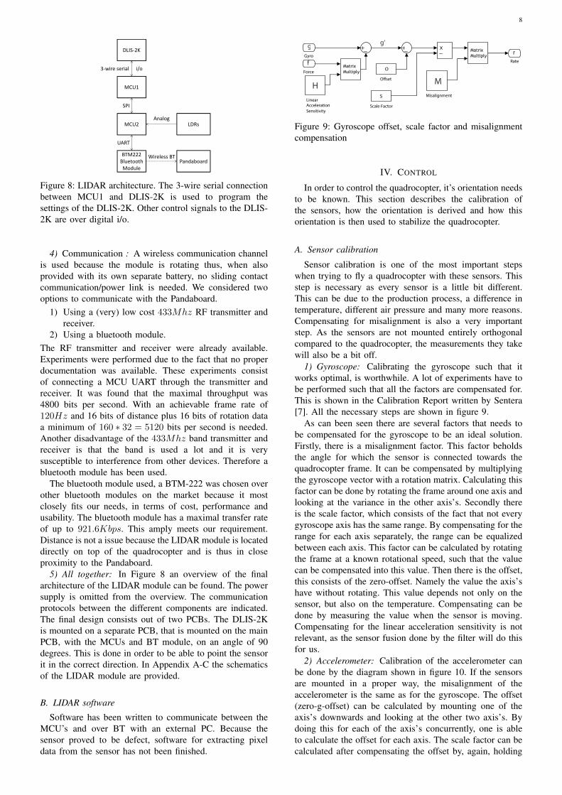
Figure 8: LIDAR architecture. The 3-wire serial connectionbetween MCU1 and DLIS-2K is used to program thesettings of the DLIS-2K. Other control signals to the DLIS-2K are over digital i/o.
4) Communication : A wireless communication channelis used because the module is rotating thus, when alsoprovided with its own separate battery, no sliding contactcommunication/power link is needed. We considered twooptions to communicate with the Pandaboard.
1) Using a (very) low cost 433Mhz RF transmitter andreceiver.
2) Using a bluetooth module.The RF transmitter and receiver were already available.Experiments were performed due to the fact that no properdocumentation was available. These experiments consistof connecting a MCU UART through the transmitter andreceiver. It was found that the maximal throughput was4800 bits per second. With an achievable frame rate of120Hz and 16 bits of distance plus 16 bits of rotation dataa minimum of 160 ∗ 32 = 5120 bits per second is needed.Another disadvantage of the 433Mhz band transmitter andreceiver is that the band is used a lot and it is verysusceptible to interference from other devices. Therefore abluetooth module has been used.
The bluetooth module used, a BTM-222 was chosen overother bluetooth modules on the market because it mostclosely fits our needs, in terms of cost, performance andusability. The bluetooth module has a maximal transfer rateof up to 921.6Kbps. This amply meets our requirement.Distance is not a issue because the LIDAR module is locateddirectly on top of the quadrocopter and is thus in closeproximity to the Pandaboard.
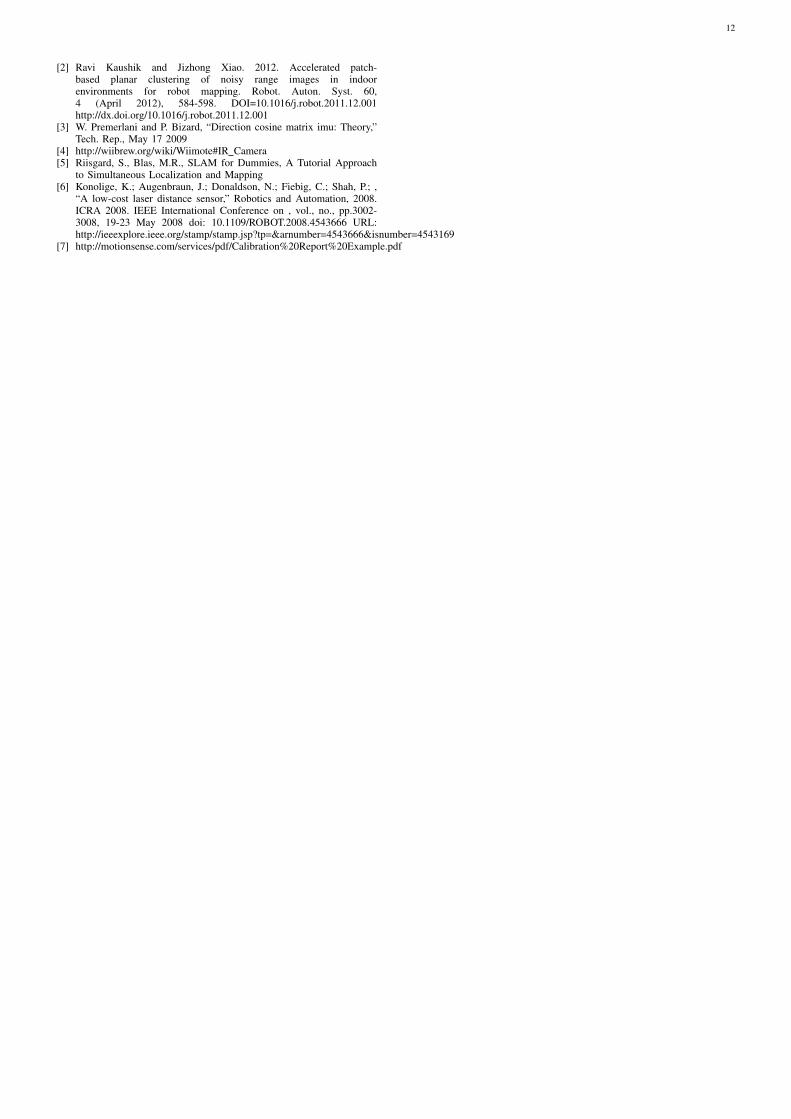
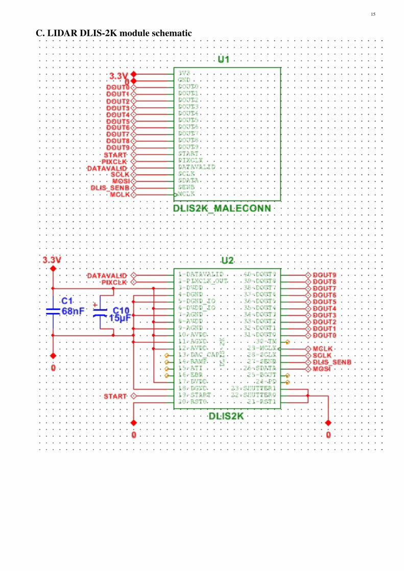
5) All together: In Figure 8 an overview of the finalarchitecture of the LIDAR module can be found. The powersupply is omitted from the overview. The communicationprotocols between the different components are indicated.The final design consists out of two PCBs. The DLIS-2Kis mounted on a separate PCB, that is mounted on the mainPCB, with the MCUs and BT module, on an angle of 90degrees. This is done in order to be able to point the sensorit in the correct direction. In Appendix A-C the schematicsof the LIDAR module are provided.
B. LIDAR software
Software has been written to communicate between theMCU’s and over BT with an external PC. Because thesensor proved to be defect, software for extracting pixeldata from the sensor has not been finished.
g' g r
f
H
o
s
M
Gyro
O�set
Misalignment
Matrix Multiply
Rate Matrix Multiply
Linear Acceleration Sensitivity
Scale Factor
Force
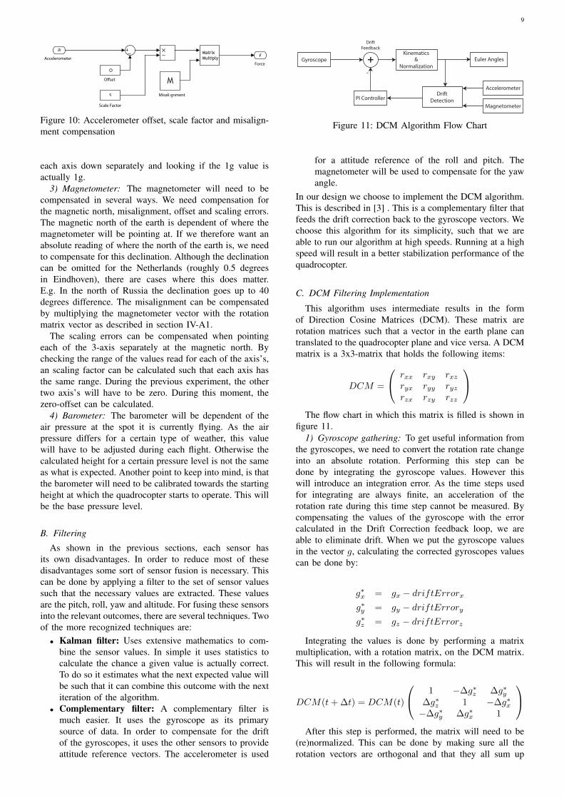
Figure 9: Gyroscope offset, scale factor and misalignmentcompensation
IV. CONTROL
In order to control the quadrocopter, it’s orientation needsto be known. This section describes the calibration ofthe sensors, how the orientation is derived and how thisorientation is then used to stabilize the quadrocopter.
A. Sensor calibration
Sensor calibration is one of the most important stepswhen trying to fly a quadrocopter with these sensors. Thisstep is necessary as every sensor is a little bit different.This can be due to the production process, a difference intemperature, different air pressure and many more reasons.Compensating for misalignment is also a very importantstep. As the sensors are not mounted entirely orthogonalcompared to the quadrocopter, the measurements they takewill also be a bit off.
1) Gyroscope: Calibrating the gyroscope such that itworks optimal, is worthwhile. A lot of experiments have tobe performed such that all the factors are compensated for.This is shown in the Calibration Report written by Sentera[7]. All the necessary steps are shown in figure 9.
As can been seen there are several factors that needs tobe compensated for the gyroscope to be an ideal solution.Firstly, there is a misalignment factor. This factor beholdsthe angle for which the sensor is connected towards thequadrocopter frame. It can be compensated by multiplyingthe gyroscope vector with a rotation matrix. Calculating thisfactor can be done by rotating the frame around one axis andlooking at the variance in the other axis’s. Secondly thereis the scale factor, which consists of the fact that not everygyroscope axis has the same range. By compensating for therange for each axis separately, the range can be equalizedbetween each axis. This factor can be calculated by rotatingthe frame at a known rotational speed, such that the valuecan be compensated into this value. Then there is the offset,this consists of the zero-offset. Namely the value the axis’shave without rotating. This value depends not only on thesensor, but also on the temperature. Compensating can bedone by measuring the value when the sensor is moving.Compensating for the linear acceleration sensitivity is notrelevant, as the sensor fusion done by the filter will do thisfor us.
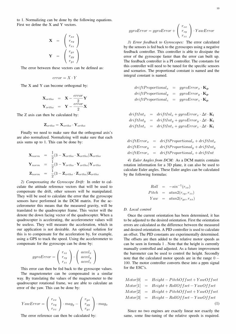
2) Accelerometer: Calibration of the accelerometer canbe done by the diagram shown in figure 10. If the sensorsare mounted in a proper way, the misalignment of theaccelerometer is the same as for the gyroscope. The offset(zero-g-offset) can be calculated by mounting one of theaxis’s downwards and looking at the other two axis’s. Bydoing this for each of the axis’s concurrently, one is ableto calculate the offset for each axis. The scale factor can becalculated after compensating the offset by, again, holding
9
Scale Factor
a
o
s
f Accelerometer
O�set
Misali gnment
Matrix Multiply
Force
M
Figure 10: Accelerometer offset, scale factor and misalign-ment compensation
each axis down separately and looking if the 1g value isactually 1g.
3) Magnetometer: The magnetometer will need to becompensated in several ways. We need compensation forthe magnetic north, misalignment, offset and scaling errors.The magnetic north of the earth is dependent of where themagnetometer will be pointing at. If we therefore want anabsolute reading of where the north of the earth is, we needto compensate for this declination. Although the declinationcan be omitted for the Netherlands (roughly 0.5 degreesin Eindhoven), there are cases where this does matter.E.g. In the north of Russia the declination goes up to 40degrees difference. The misalignment can be compensatedby multiplying the magnetometer vector with the rotationmatrix vector as described in section IV-A1.
The scaling errors can be compensated when pointingeach of the 3-axis separately at the magnetic north. Bychecking the range of the values read for each of the axis’s,an scaling factor can be calculated such that each axis hasthe same range. During the previous experiment, the othertwo axis’s will have to be zero. During this moment, thezero-offset can be calculated.
4) Barometer: The barometer will be dependent of theair pressure at the spot it is currently flying. As the airpressure differs for a certain type of weather, this valuewill have to be adjusted during each flight. Otherwise thecalculated height for a certain pressure level is not the sameas what is expected. Another point to keep into mind, is thatthe barometer will need to be calibrated towards the startingheight at which the quadrocopter starts to operate. This willbe the base pressure level.
B. Filtering
As shown in the previous sections, each sensor hasits own disadvantages. In order to reduce most of thesedisadvantages some sort of sensor fusion is necessary. Thiscan be done by applying a filter to the set of sensor valuessuch that the necessary values are extracted. These valuesare the pitch, roll, yaw and altitude. For fusing these sensorsinto the relevant outcomes, there are several techniques. Twoof the more recognized techniques are:
• Kalman filter: Uses extensive mathematics to com-bine the sensor values. In simple it uses statistics tocalculate the chance a given value is actually correct.To do so it estimates what the next expected value willbe such that it can combine this outcome with the nextiteration of the algorithm.
• Complementary filter: A complementary filter ismuch easier. It uses the gyroscope as its primarysource of data. In order to compensate for the driftof the gyroscopes, it uses the other sensors to provideattitude reference vectors. The accelerometer is used
Gyroscope
Accelerometer
Euler Angles
Magnetometer
Kinematics&
Normalization
DriftDetectionPI Controller
DriftFeedback
+-
Figure 11: DCM Algorithm Flow Chart
for a attitude reference of the roll and pitch. Themagnetometer will be used to compensate for the yawangle.
In our design we choose to implement the DCM algorithm.This is described in [3] . This is a complementary filter thatfeeds the drift correction back to the gyroscope vectors. Wechoose this algorithm for its simplicity, such that we areable to run our algorithm at high speeds. Running at a highspeed will result in a better stabilization performance of thequadrocopter.
C. DCM Filtering Implementation
This algorithm uses intermediate results in the formof Direction Cosine Matrices (DCM). These matrix arerotation matrices such that a vector in the earth plane cantranslated to the quadrocopter plane and vice versa. A DCMmatrix is a 3x3-matrix that holds the following items:
DCM =
rxx rxy rxzryx ryy ryzrzx rzy rzz
The flow chart in which this matrix is filled is shown in
figure 11.1) Gyroscope gathering: To get useful information from
the gyroscopes, we need to convert the rotation rate changeinto an absolute rotation. Performing this step can bedone by integrating the gyroscope values. However thiswill introduce an integration error. As the time steps usedfor integrating are always finite, an acceleration of therotation rate during this time step cannot be measured. Bycompensating the values of the gyroscope with the errorcalculated in the Drift Correction feedback loop, we areable to eliminate drift. When we put the gyroscope valuesin the vector g, calculating the corrected gyroscopes valuescan be done by:
g∗x = gx − driftErrorx
g∗y = gy − driftErrory
g∗z = gz − driftErrorz
Integrating the values is done by performing a matrixmultiplication, with a rotation matrix, on the DCM matrix.This will result in the following formula:
DCM(t+ ∆t) = DCM(t)
1 −∆g∗z ∆g∗y∆g∗z 1 −∆g∗x−∆g∗y ∆g∗x 1
After this step is performed, the matrix will need to be
(re)normalized. This can be done by making sure all therotation vectors are orthogonal and that they all sum up
10
to 1. Normalizing can be done by the following equations.First we define the X and Y vectors.
X =
rxxrxyrxz
Y =
ryxryyryz
The error between these vectors can be defined as:
error = X · Y
The X and Y can become orthogonal by:
Xortho = X− error
2Y
Yortho = Y − error
2X
The Z axis can then be calculated by:
Zortho = Xortho ·Yortho
Finally we need to make sure that the orthogonal axis’sare also normalized. Normalizing will make sure that eachaxis sums up to 1. This can be done by:
Xnorm =1
2(3 −Xortho ·Xortho)Xortho
Ynorm =1
2(3 −Yortho ·Yortho)Yortho
Znorm =1
2(3 − Zortho · Zortho)Zortho
2) Compensating the Gyroscope Drift: In order to cal-culate the attitude reference vectors that will be used tocompensate the drift, other sensors will be manipulated.They will be used to calculate the error that the gyroscopesensors have performed in the DCM matrix. For the ac-celerometer this means that the measured gravity, will betranslated to the quadrocopter frame. This vector will thedenote the down facing vector of the quadrocopter. When aquadrocopter is accelerating, the accelerometer values willbe useless. They will measure the acceleration, which inour application is not desirable. An optional solution forthis is to compensate for the acceleration by, for example,using a GPS to track the speed. Using the accelerometer tocompensate for the gyroscope can be done by:
gyroError =
rzxrzyrzz
·
accelxaccelyaccelz
This error can then be fed back to the gyroscope values.The magnetometer can be compensated in a similar
way. By translating the values of the magnetometer to thequadrocopter rotational frame, we are able to calculate anerror of the yaw. This can be done by:
Y awError =
rxxrxyrxz
·magy −
ryxryyryz
·magx
The error reference can then be calculated by:
gyroError = gyroError +
rzxrzyrzz
· Y awError
3) Error feedback to Gyroscopes: The error calculatedby the sensors is fed back to the gyroscopes using a negativefeedback controller. This controller is able to dissipate theerror of the gyroscope faster than the error can built up.The feedback controller is a PI controller. The constants forthis controller will need to be tuned for the specific sensorsand scenarios. The proportional constant is named and theintegral constant is named.
driftProportionalx = gyroErrorx ·Kp
driftProportionaly = gyroErrory ·Kp
driftProportionalz = gyroErrorz ·Kp
driftIntx = driftInlx + gyroErrorx · ∆t ·Ki
driftInty = driftInty + gyroErrory · ∆t ·Ki
driftIntz = driftIntz + gyroErrorz · ∆t ·Ki
driftErrorx = driftProportionalx + driftIntx
driftErrory = driftProportionaly + driftInty
driftErrorz = driftProportionalz + driftInt
4) Euler Angles from DCM: As a DCM matrix containsrotation information for a 3D plane, it can also be used tocalculate Euler angles. These Euler angles can be calculatedby the following formulas:
Roll = −sin−1(rzx)
Pitch = atan2(rzy, rzz)
Y aw = atan2(ryx, rxx)
D. Local control
Once the current orientation has been determined, it hasto be adjusted to the desired orientation. First the orientationerrors are calculated as the difference between the measuredand desired orientation. A PID controller is used to calculatean offset. The PID constants are experimentally determined.The offsets are then added to the relative motor speeds ascan be seen in formula 1 . Note that the height is currentlymanually controlled and adjusted. As a future improvementthe barometer can be used to control the height. Secondlynote that the calculated motor speeds are in the range 0 −100. The motor controller converts these into a ppm signalfor the ESC’s.
Motor[0] = Height− PitchOffset+ Y awOffset
Motor[1] = Height+RollOffset− Y awOffset
Motor[2] = Height+ PitchOffset+ Y awOffset
Motor[3] = Height−RollOffset− Y awOffset
(1)
Since no two engines are exactly linear nor exactly thesame, some fine-tuning of the relative speeds is required.
11
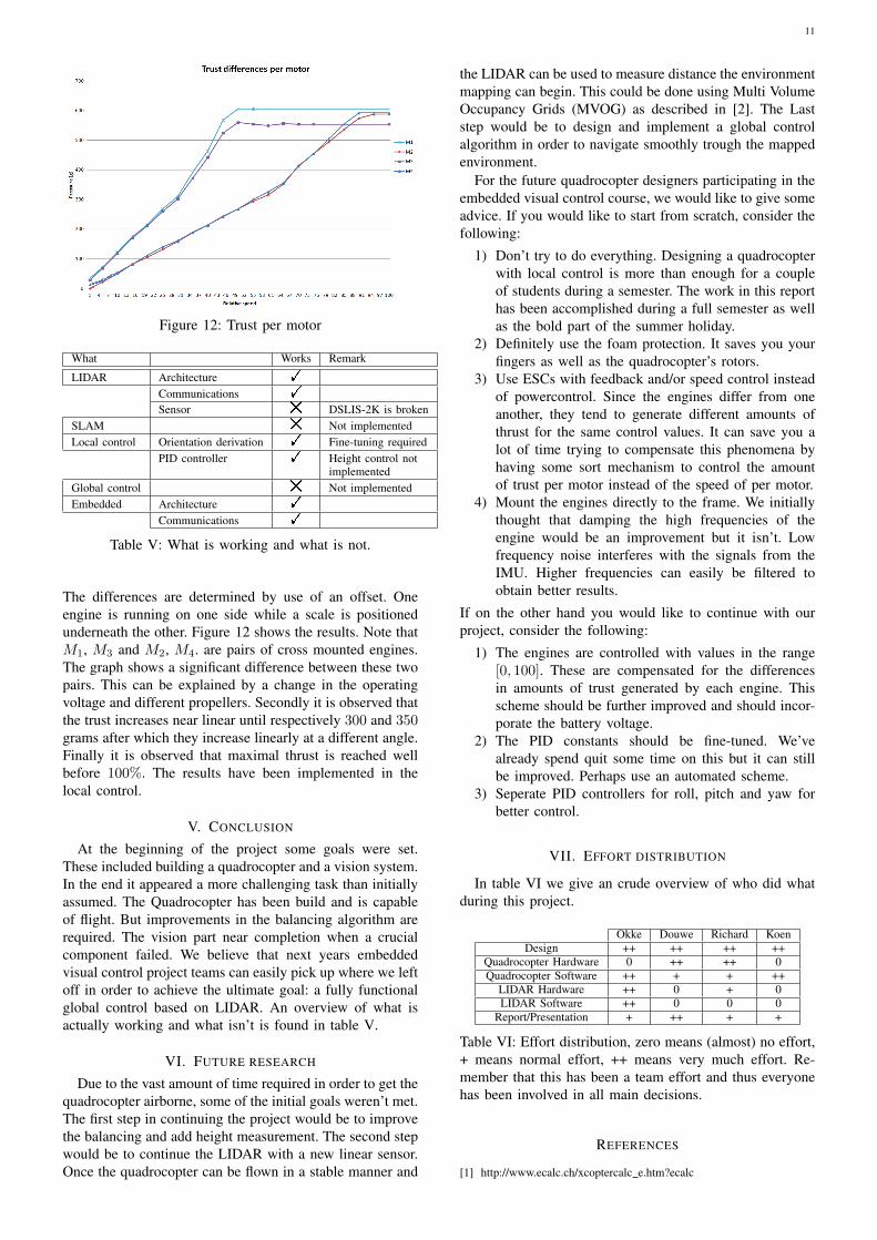
Figure 12: Trust per motor
What Works Remark
LIDAR Architecture !
Communications !
Sensor # DSLIS-2K is brokenSLAM # Not implementedLocal control Orientation derivation ! Fine-tuning required
PID controller ! Height control notimplemented
Global control # Not implementedEmbedded Architecture !
Communications !
Table V: What is working and what is not.
The differences are determined by use of an offset. Oneengine is running on one side while a scale is positionedunderneath the other. Figure 12 shows the results. Note thatM1, M3 and M2, M4. are pairs of cross mounted engines.The graph shows a significant difference between these twopairs. This can be explained by a change in the operatingvoltage and different propellers. Secondly it is observed thatthe trust increases near linear until respectively 300 and 350grams after which they increase linearly at a different angle.Finally it is observed that maximal thrust is reached wellbefore 100%. The results have been implemented in thelocal control.
V. CONCLUSION
At the beginning of the project some goals were set.These included building a quadrocopter and a vision system.In the end it appeared a more challenging task than initiallyassumed. The Quadrocopter has been build and is capableof flight. But improvements in the balancing algorithm arerequired. The vision part near completion when a crucialcomponent failed. We believe that next years embeddedvisual control project teams can easily pick up where we leftoff in order to achieve the ultimate goal: a fully functionalglobal control based on LIDAR. An overview of what isactually working and what isn’t is found in table V.
VI. FUTURE RESEARCH
Due to the vast amount of time required in order to get thequadrocopter airborne, some of the initial goals weren’t met.The first step in continuing the project would be to improvethe balancing and add height measurement. The second stepwould be to continue the LIDAR with a new linear sensor.Once the quadrocopter can be flown in a stable manner and
the LIDAR can be used to measure distance the environmentmapping can begin. This could be done using Multi VolumeOccupancy Grids (MVOG) as described in [2]. The Laststep would be to design and implement a global controlalgorithm in order to navigate smoothly trough the mappedenvironment.
For the future quadrocopter designers participating in theembedded visual control course, we would like to give someadvice. If you would like to start from scratch, consider thefollowing:
1) Don’t try to do everything. Designing a quadrocopterwith local control is more than enough for a coupleof students during a semester. The work in this reporthas been accomplished during a full semester as wellas the bold part of the summer holiday.
2) Definitely use the foam protection. It saves you yourfingers as well as the quadrocopter’s rotors.
3) Use ESCs with feedback and/or speed control insteadof powercontrol. Since the engines differ from oneanother, they tend to generate different amounts ofthrust for the same control values. It can save you alot of time trying to compensate this phenomena byhaving some sort mechanism to control the amountof trust per motor instead of the speed of per motor.
4) Mount the engines directly to the frame. We initiallythought that damping the high frequencies of theengine would be an improvement but it isn’t. Lowfrequency noise interferes with the signals from theIMU. Higher frequencies can easily be filtered toobtain better results.
If on the other hand you would like to continue with ourproject, consider the following:
1) The engines are controlled with values in the range[0, 100]. These are compensated for the differencesin amounts of trust generated by each engine. Thisscheme should be further improved and should incor-porate the battery voltage.
2) The PID constants should be fine-tuned. We’vealready spend quit some time on this but it can stillbe improved. Perhaps use an automated scheme.
3) Seperate PID controllers for roll, pitch and yaw forbetter control.
VII. EFFORT DISTRIBUTION
In table VI we give an crude overview of who did whatduring this project.
Okke Douwe Richard KoenDesign ++ ++ ++ ++
Quadrocopter Hardware 0 ++ ++ 0Quadrocopter Software ++ + + ++
LIDAR Hardware ++ 0 + 0LIDAR Software ++ 0 0 0
Report/Presentation + ++ + +
Table VI: Effort distribution, zero means (almost) no effort,+ means normal effort, ++ means very much effort. Re-member that this has been a team effort and thus everyonehas been involved in all main decisions.
REFERENCES
[1] http://www.ecalc.ch/xcoptercalc e.htm?ecalc
12
[2] Ravi Kaushik and Jizhong Xiao. 2012. Accelerated patch-based planar clustering of noisy range images in indoorenvironments for robot mapping. Robot. Auton. Syst. 60,4 (April 2012), 584-598. DOI=10.1016/j.robot.2011.12.001http://dx.doi.org/10.1016/j.robot.2011.12.001
[3] W. Premerlani and P. Bizard, “Direction cosine matrix imu: Theory,”Tech. Rep., May 17 2009
[4] http://wiibrew.org/wiki/Wiimote#IR Camera[5] Riisgard, S., Blas, M.R., SLAM for Dummies, A Tutorial Approach
to Simultaneous Localization and Mapping[6] Konolige, K.; Augenbraun, J.; Donaldson, N.; Fiebig, C.; Shah, P.; ,
“A low-cost laser distance sensor,” Robotics and Automation, 2008.ICRA 2008. IEEE International Conference on , vol., no., pp.3002-3008, 19-23 May 2008 doi: 10.1109/ROBOT.2008.4543666 URL:http://ieeexplore.ieee.org/stamp/stamp.jsp?tp=&arnumber=4543666&isnumber=4543169
[7] http://motionsense.com/services/pdf/Calibration%20Report%20Example.pdf
13
APPENDIX
A. LIDAR main 1 schematic
14
B. LIDAR main 2 schematic
15
C. LIDAR DLIS-2K module schematic
16
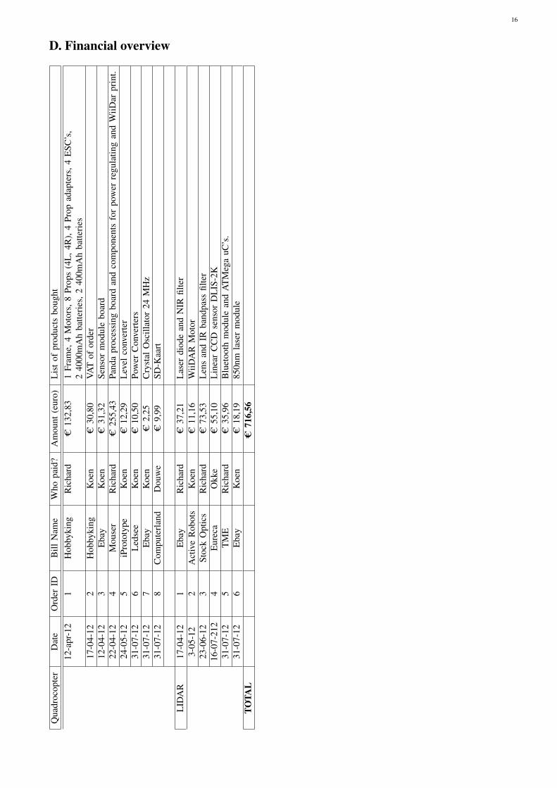
D. Financial overviewQ
uadr
ocop
ter
Dat
eO
rder
IDB
illN
ame
Who
paid
?A
mou
nt(e
uro)
Lis
tof
prod
ucts
boug
ht12
-apr
-12
1H
obby
king
Ric
hard
C13
2,83
1Fr
ame,
4M
otor
s,8
Prop
s(4
L,4
R),
4Pr
opad
apte
rs,4
ESC
’s,
240
00m
Ah
batte
ries
,240
0mA
hba
tteri
es17
-04-
122
Hob
byki
ngK
oen
C30
,80
VAT
ofor
der
12-0
4-12
3E
bay
Koe
nC
31,3
2Se
nsor
mod
ule
boar
d22
-04-
124
Mou
ser
Ric
hard
C25
5,43
Pand
apr
oces
sing
boar
dan
dco
mpo
nent
sfo
rpo
wer
regu
latin
gan
dW
iiDar
prin
t.24
-05-
125
iPro
toty
peK
oen
C12
,29
Lev
elco
nver
ter
31-0
7-12
6L
edse
eK
oen
C10
,50
Pow
erC
onve
rter
s31
-07-
127
Eba
yK
oen
C2,
25C
ryst
alO
scill
ator
24M
Hz
31-0
7-12
8C
ompu
terl
and
Dou
we
C9,
99SD
-Kaa
rt
LID
AR
17-0
4-12
1E
bay
Ric
hard
C37
,21
Las
erdi
ode
and
NIR
filte
r3-
05-1
22
Act
ive
Rob
ots
Koe
nC
11,1
6W
iiDA
RM
otor
23-0
6-12
3St
ock
Opt
ics
Ric
hard
C73
,53
Len
san
dIR
band
pass
filte
r16
-07-
212
4E
urec
aO
kke
C55
,10
Lin
ear
CC
Dse
nsor
DL
IS-2
K31
-07-
125
TM
ER
icha
rdC
35,9
6B
luet
ooth
mod
ule
and
AT
Meg
auC
’s.
31-0
7-12
6E
bay
Koe
nC
18,1
985
0nm
lase
rm
odul
eTO
TAL
C71
6,56