Embed Size (px)
Citation preview
Quality Crimp Handbook
Order No: TM-638000029 Release Date: 09-04-03 UNCONTROLLED COPY Page 1 of 24
Revision: D Revision Date: 12-23-09
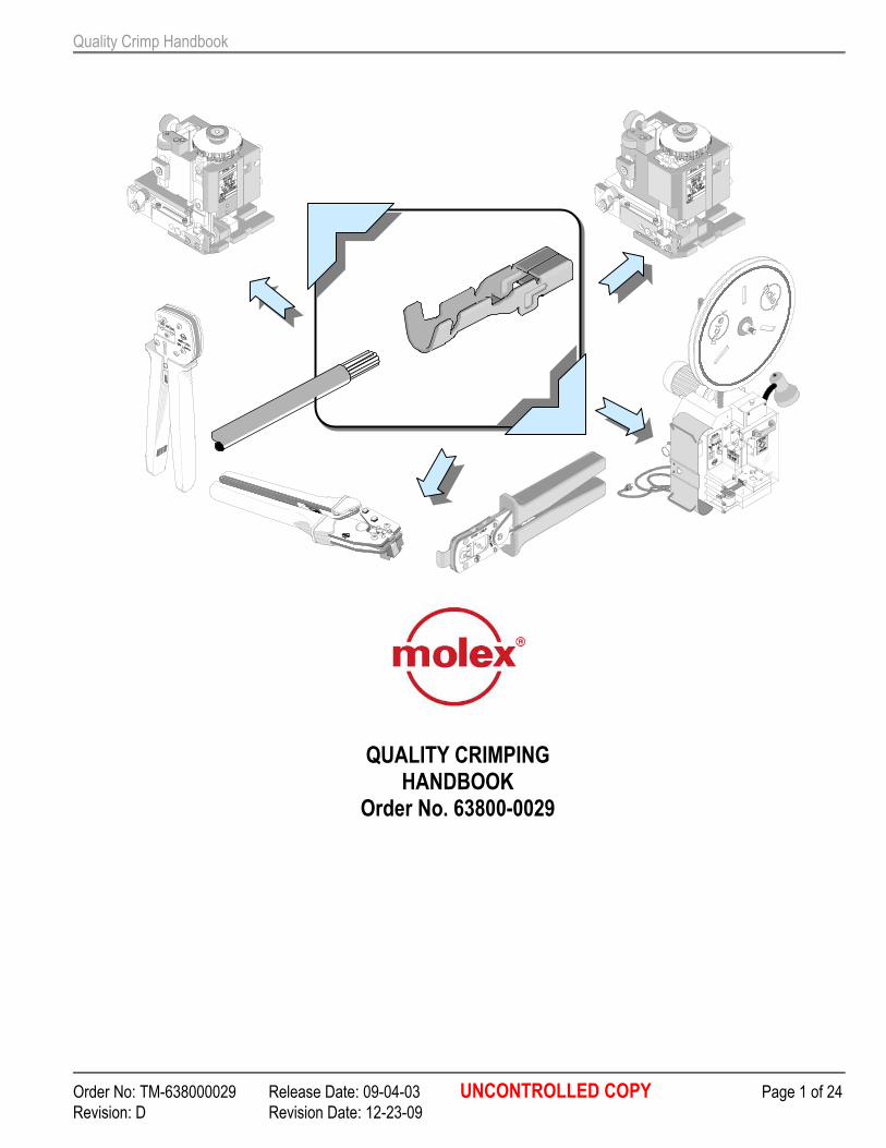
QUALITY CRIMPING HANDBOOK
Order No. 63800-0029

Quality Crimp Handbook
Order No: TM-638000029 Release Date: 09-04-03 UNCONTROLLED COPY Page 2 of 24
Revision: D Revision Date: 12-23-09
Table of Contents
SECTION
1 Introduction to Crimp Technology
2 Purpose
3 Scope
4 Definitions
5 Associated Materials
6 Procedures
7 Measurement
8 Crimp Process Control
9 Troubleshooting
10 Wire Gauge Chart
Quality Crimp Handbook
Order No: TM-638000029 Release Date: 09-04-03 UNCONTROLLED COPY Page 3 of 24
Revision: D Revision Date: 12-23-09
SECTION 1
INTRODUCTION TO CRIMP TECHNOLOGY Developed to replace the need to solder terminations, crimping technology provides a high quality connection between a terminal and a wire at a relatively low applied cost. The methods for applying crimp terminations depend on the application and volume, and range from hand-held devices to fully automated systems. The application methods include a basic hand tool, a press and die set, a stripper crimper, or a fully automatic wire processing system. However, no matter what method is used, the setup of each tool is critical for achieving a quality crimp. Today, many OEM companies are using Statistical Process Control (SPC) to continuously improve their crimp terminations. Crimp termination is a complex process and to ensure consistent quality it is necessary to understand the variability and inter-relational interactions that the technology involves. Without a thorough understanding of the crimping process, and all the factors that can affect it, the result may not meet expectations. The three key elements in the crimping process are the terminal, the wire, and the tooling. Terminal For most applications, it is not economically practical for connector manufacturers to design a terminal to accept one wire size, one wire stranding, and one insulation diameter (UL type). Most terminals accommodate many wire sizes, stranding, and a range of insulation diameters, and the terminals are designed to meet acceptable levels over this entire range.
Wire The wire stranding and insulation type can vary widely within one wire size. For example, there is more than 18% more material in an 18 AWG by 19-strand wire than an 18 AWG by 16-strand wire. The insulation diameter of an 18 AWG wire can range from 1.78mm (.070") to over 4.57mm (.180"). Wire strands can be copper, tinned, over coated, or top coated. Wire insulation materials, thickness, and durometers vary from application to application.
Tooling What type of tooling does the application require? Does the application require hand stripping of the wire or does the volume dictate an automatic wire-stripping machine? Does the application and volume require hand tools, press and die, or fully automatic wire process machines? Crimping with a manual hand tool, semi-automatic press and die, or fully automatic wire processor, all involve different levels of variability. The terminal, wire, and type of application tooling all affect the quality of the completed terminations.
Quality Crimp Handbook
Order No: TM-638000029 Release Date: 09-04-03 UNCONTROLLED COPY Page 4 of 24
Revision: D Revision Date: 12-23-09
SECTION 2
PURPOSE This handbook provides general guidelines and procedures for understanding and achieving acceptable crimp terminations. A glossary in Section 4 lists common terms and definitions. Section 5 lists the tools that are necessary to take accurate measurements and evaluate the crimp's acceptability. The tooling setup is critical in determining the quality of the finished crimp. The attributes that need to be considered include crimp height, conductor brush, bell mouth, and cut-off tab and strip length and insulation position. Variability in one or more of these attributes can reduce the measured pull force. It can be difficult to establish acceptable variability limits because the attributes all interact with one another. For example, a track adjustment for bell mouth also will change the cut-off tab length and the insulation wire position while strip length and wire locations affect the conductor brush and insulation position. Adjusting the insulation crimp height may result in a slight change to the conductor crimp height measurement. It may be necessary for the setup person to make multiple adjustments before establishing an optimal setup. The order the setup is done may help reduce the number of repetitions required for an optimum setup. Section 6 has a flowchart for a process setup while Section 9 is a troubleshooting guide for common problems. Using Statistical Process Control (SPC) during the crimping process can help minimize the amount of defects. Section 8 provides a general explanation of the benefits of using SPC. This handbook is structured so that parts, or all, of its contents can be used as a procedural guide for ISO requirements.
Quality Crimp Handbook
Order No: TM-638000029 Release Date: 09-04-03 UNCONTROLLED COPY Page 5 of 24
Revision: D Revision Date: 12-23-09
SECTION 3
SCOPE
This handbook is intended for Molex customers who are crimping Molex open barrel crimp terminals and are using Molex tooling, primarily in semiautomatic or automatic wire processing termination methods.
The handbook's contents may slightly differ from other connector manufacturers' guidelines or individual company procedures. This handbook provides a basic overview of what to look for in an acceptable crimp. It is not intended to replace individual product and/or tooling specifications. Individual terminals or applications may have special requirements. Tooling limitations also may not permit an attribute to be adjusted to meet optimum requirements.
Quality Crimp Handbook
Order No: TM-638000029 Release Date: 09-04-03 UNCONTROLLED COPY Page 6 of 24
Revision: D Revision Date: 12-23-09
INSULATION CRIMP
BRUSH
STRIP LENGTH
BELL MOUTH
CRIMP HEIGHT
CONDUCTOR CRIMP
CUT-OFF TAB
SEAM
EXTRUSIONS
EXTRUSION EXTRUSION
TERMINAL CROSS SECTION VIEW
Figure 4-1
BEND DOWN
BEND UP
ROLLING
TWISTING
SECTION 4
DEFINITIONS
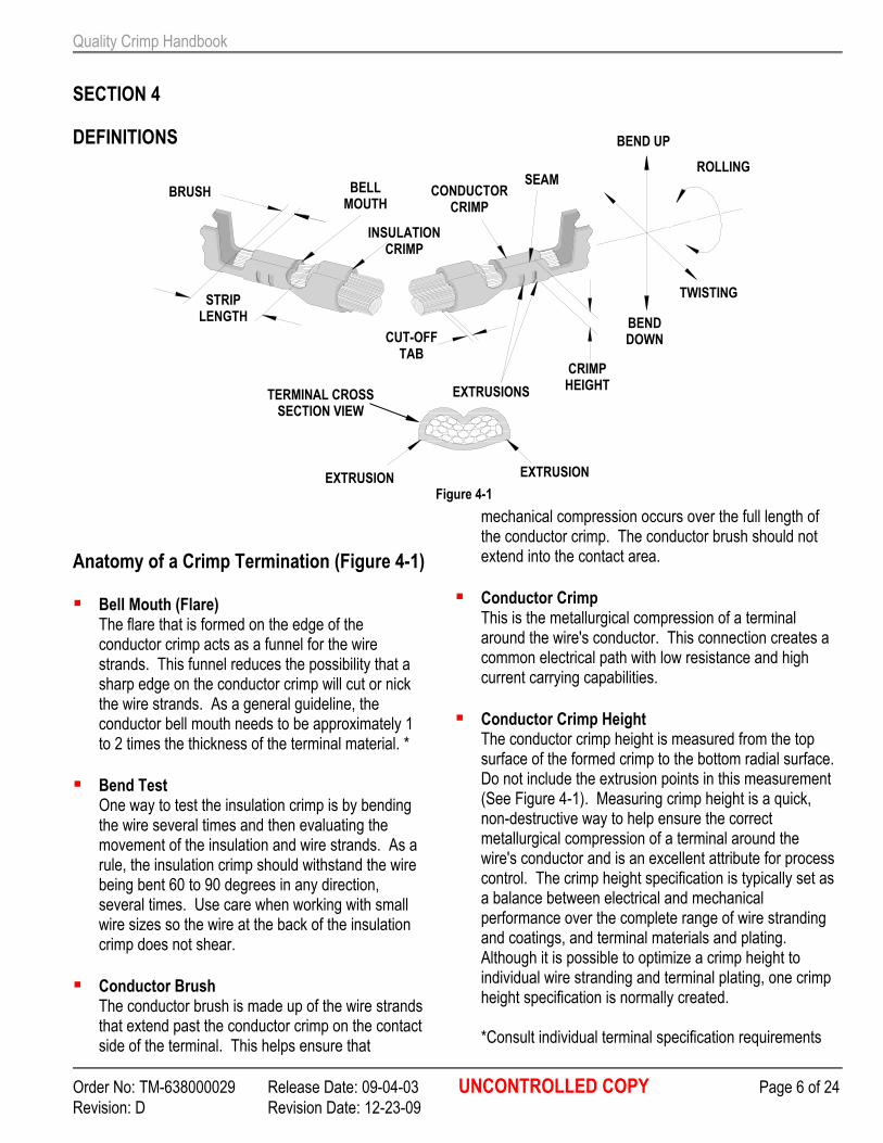
Anatomy of a Crimp Termination (Figure 4-1)
� Bell Mouth (Flare) The flare that is formed on the edge of the conductor crimp acts as a funnel for the wire strands. This funnel reduces the possibility that a sharp edge on the conductor crimp will cut or nick the wire strands. As a general guideline, the conductor bell mouth needs to be approximately 1 to 2 times the thickness of the terminal material. *
� Bend Test One way to test the insulation crimp is by bending the wire several times and then evaluating the movement of the insulation and wire strands. As a rule, the insulation crimp should withstand the wire being bent 60 to 90 degrees in any direction, several times. Use care when working with small wire sizes so the wire at the back of the insulation crimp does not shear.
� Conductor Brush The conductor brush is made up of the wire strands that extend past the conductor crimp on the contact side of the terminal. This helps ensure that
mechanical compression occurs over the full length of the conductor crimp. The conductor brush should not extend into the contact area.
� Conductor Crimp This is the metallurgical compression of a terminal around the wire's conductor. This connection creates a common electrical path with low resistance and high current carrying capabilities.
� Conductor Crimp Height The conductor crimp height is measured from the top surface of the formed crimp to the bottom radial surface. Do not include the extrusion points in this measurement (See Figure 4-1). Measuring crimp height is a quick, non-destructive way to help ensure the correct metallurgical compression of a terminal around the wire's conductor and is an excellent attribute for process control. The crimp height specification is typically set as a balance between electrical and mechanical performance over the complete range of wire stranding and coatings, and terminal materials and plating. Although it is possible to optimize a crimp height to individual wire stranding and terminal plating, one crimp height specification is normally created. *Consult individual terminal specification requirements
Quality Crimp Handbook
Order No: TM-638000029 Release Date: 09-04-03 UNCONTROLLED COPY Page 7 of 24
Revision: D Revision Date: 12-23-09
28.5
29.5
30.5
31.5
Th
ou
sa
nd
ths
Measurements
Cri
mp
He
igh
t
1 2 3 4 5 6 7 8 9 10 11 12 13 14 15 16 17 18 19 20 21 22 23 24 25
Sample
Contol Limit
Control Limit
Upper Specification
Lower Specification
Example Control Chart
Figure 4-3
Figure 4-2
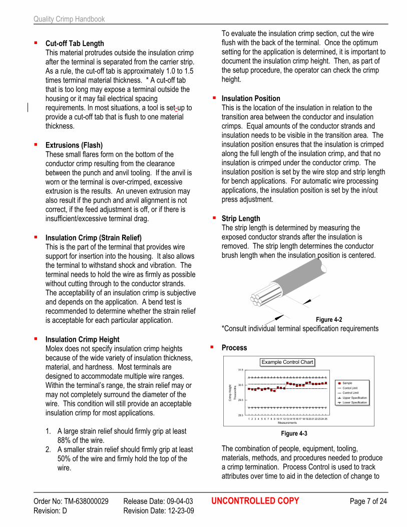
� Cut-off Tab Length This material protrudes outside the insulation crimp after the terminal is separated from the carrier strip. As a rule, the cut-off tab is approximately 1.0 to 1.5 times terminal material thickness. * A cut-off tab that is too long may expose a terminal outside the housing or it may fail electrical spacing requirements. In most situations, a tool is set-up to provide a cut-off tab that is flush to one material thickness.
� Extrusions (Flash) These small flares form on the bottom of the conductor crimp resulting from the clearance between the punch and anvil tooling. If the anvil is worn or the terminal is over-crimped, excessive extrusion is the results. An uneven extrusion may also result if the punch and anvil alignment is not correct, if the feed adjustment is off, or if there is insufficient/excessive terminal drag.
� Insulation Crimp (Strain Relief) This is the part of the terminal that provides wire support for insertion into the housing. It also allows the terminal to withstand shock and vibration. The terminal needs to hold the wire as firmly as possible without cutting through to the conductor strands. The acceptability of an insulation crimp is subjective and depends on the application. A bend test is recommended to determine whether the strain relief is acceptable for each particular application.
� Insulation Crimp Height Molex does not specify insulation crimp heights because of the wide variety of insulation thickness, material, and hardness. Most terminals are designed to accommodate multiple wire ranges. Within the terminal’s range, the strain relief may or may not completely surround the diameter of the wire. This condition will still provide an acceptable insulation crimp for most applications. 1. A large strain relief should firmly grip at least
88% of the wire. 2. A smaller strain relief should firmly grip at least
50% of the wire and firmly hold the top of the wire.
To evaluate the insulation crimp section, cut the wire flush with the back of the terminal. Once the optimum setting for the application is determined, it is important to document the insulation crimp height. Then, as part of the setup procedure, the operator can check the crimp height.
� Insulation Position This is the location of the insulation in relation to the transition area between the conductor and insulation crimps. Equal amounts of the conductor strands and insulation needs to be visible in the transition area. The insulation position ensures that the insulation is crimped along the full length of the insulation crimp, and that no insulation is crimped under the conductor crimp. The insulation position is set by the wire stop and strip length for bench applications. For automatic wire processing applications, the insulation position is set by the in/out press adjustment.
� Strip Length The strip length is determined by measuring the exposed conductor strands after the insulation is removed. The strip length determines the conductor brush length when the insulation position is centered. *Consult individual terminal specification requirements
� Process The combination of people, equipment, tooling, materials, methods, and procedures needed to produce a crimp termination. Process Control is used to track attributes over time to aid in the detection of change to
Quality Crimp Handbook
Order No: TM-638000029 Release Date: 09-04-03 UNCONTROLLED COPY Page 8 of 24
Revision: D Revision Date: 12-23-09
Figure 4-4
Figure 4-6
PUNCHES
WIRE
ANVILS TERMINALS
Figure 4-5
RAM
PRESS BASE PLATE
SHUT HEIGHT GAUGE
the process. Detecting a process change when it happens helps prevent many thousands of bad crimps.
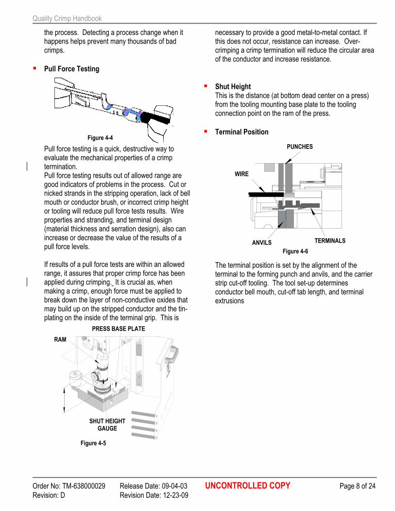
� Pull Force Testing Pull force testing is a quick, destructive way to evaluate the mechanical properties of a crimp termination. Pull force testing results out of allowed range are good indicators of problems in the process. Cut or nicked strands in the stripping operation, lack of bell mouth or conductor brush, or incorrect crimp height or tooling will reduce pull force tests results. Wire properties and stranding, and terminal design (material thickness and serration design), also can increase or decrease the value of the results of a pull force levels. If results of a pull force tests are within an allowed range, it assures that proper crimp force has been applied during crimping. It is crucial as, when making a crimp, enough force must be applied to break down the layer of non-conductive oxides that may build up on the stripped conductor and the tin-plating on the inside of the terminal grip. This is
necessary to provide a good metal-to-metal contact. If this does not occur, resistance can increase. Over-crimping a crimp termination will reduce the circular area of the conductor and increase resistance.
� Shut Height This is the distance (at bottom dead center on a press) from the tooling mounting base plate to the tooling connection point on the ram of the press.
� Terminal Position The terminal position is set by the alignment of the terminal to the forming punch and anvils, and the carrier strip cut-off tooling. The tool set-up determines conductor bell mouth, cut-off tab length, and terminal extrusions
Quality Crimp Handbook
Order No: TM-638000029 Release Date: 09-04-03 UNCONTROLLED COPY Page 9 of 24
Revision: D Revision Date: 12-23-09
SECTION 5
ASSOCIATED MATERIALS
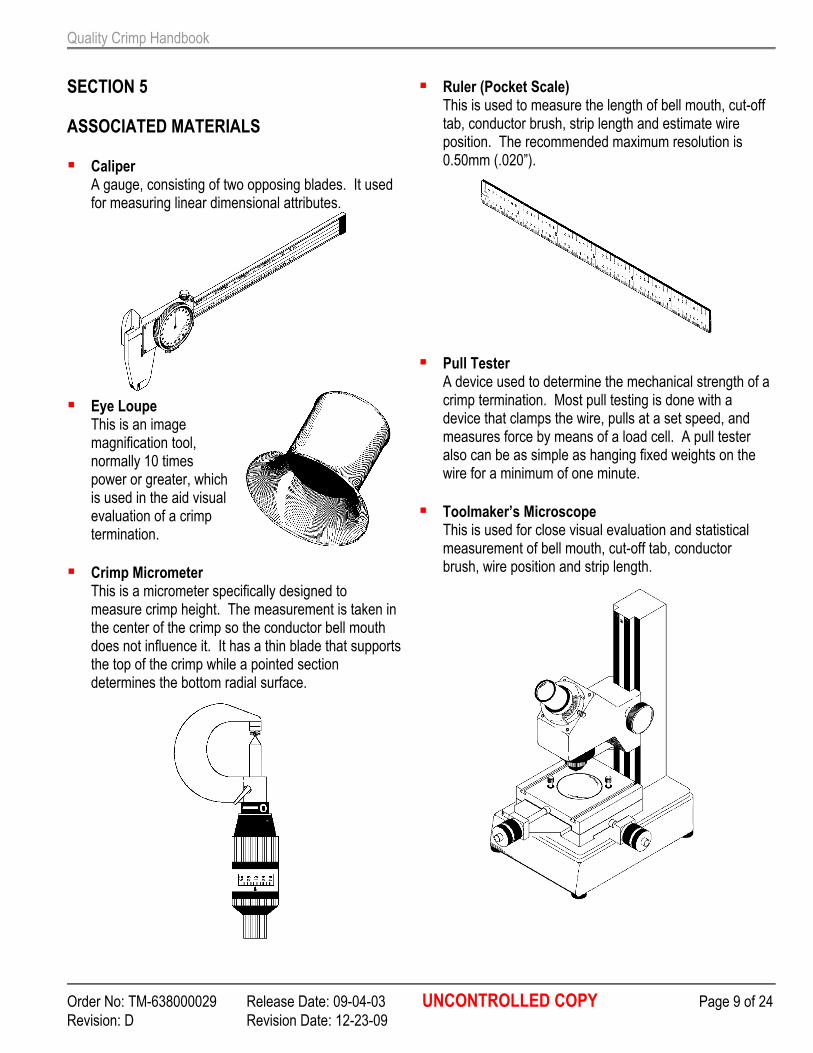
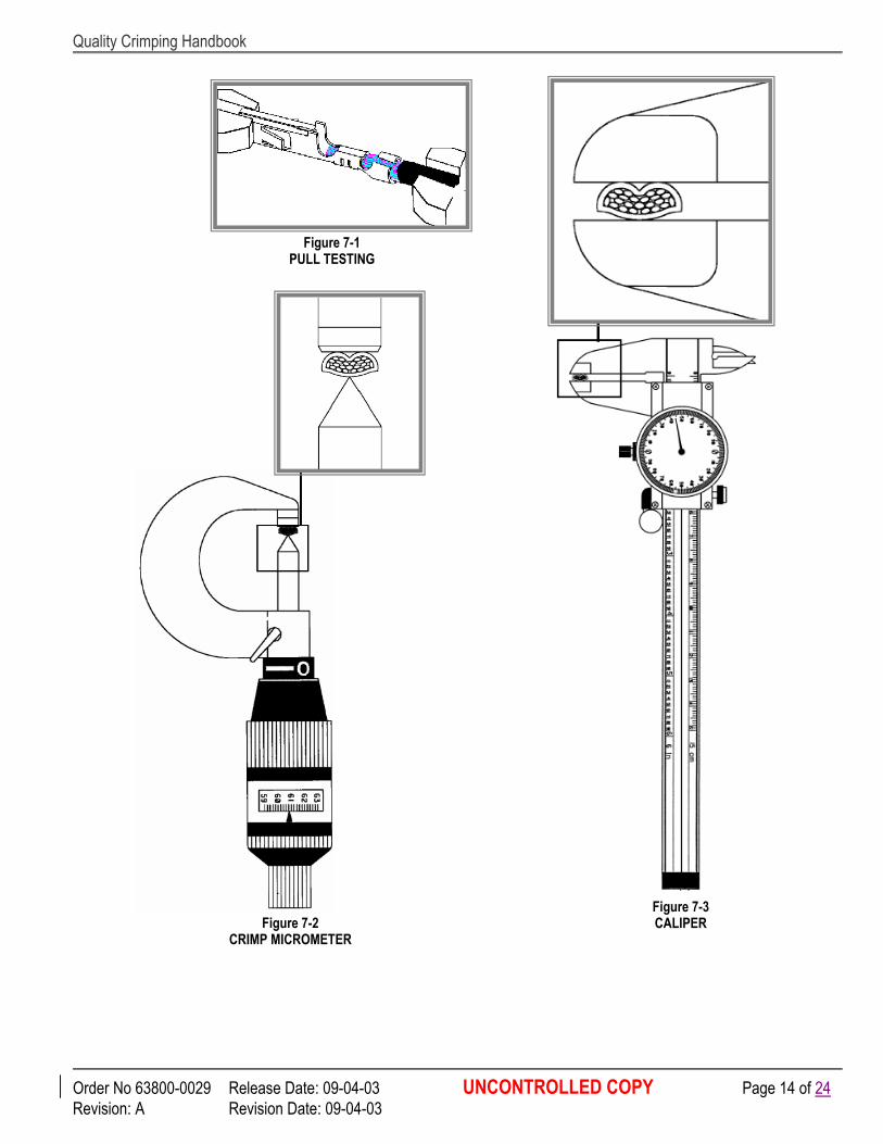
� Caliper A gauge, consisting of two opposing blades. It used for measuring linear dimensional attributes.
� Eye Loupe This is an image magnification tool, normally 10 times power or greater, which is used in the aid visual evaluation of a crimp termination.
� Crimp Micrometer This is a micrometer specifically designed to measure crimp height. The measurement is taken in the center of the crimp so the conductor bell mouth does not influence it. It has a thin blade that supports the top of the crimp while a pointed section determines the bottom radial surface.
� Ruler (Pocket Scale) This is used to measure the length of bell mouth, cut-off tab, conductor brush, strip length and estimate wire position. The recommended maximum resolution is 0.50mm (.020”).
� Pull Tester A device used to determine the mechanical strength of a crimp termination. Most pull testing is done with a device that clamps the wire, pulls at a set speed, and measures force by means of a load cell. A pull tester also can be as simple as hanging fixed weights on the wire for a minimum of one minute.
� Toolmaker’s Microscope This is used for close visual evaluation and statistical measurement of bell mouth, cut-off tab, conductor brush, wire position and strip length.
Quality Crimp Handbook
Order No: TM-638000029 Release Date: 09-04-03 UNCONTROLLED COPY Page 10 of 24
Revision: D Revision Date: 12-23-09
SECTION 6
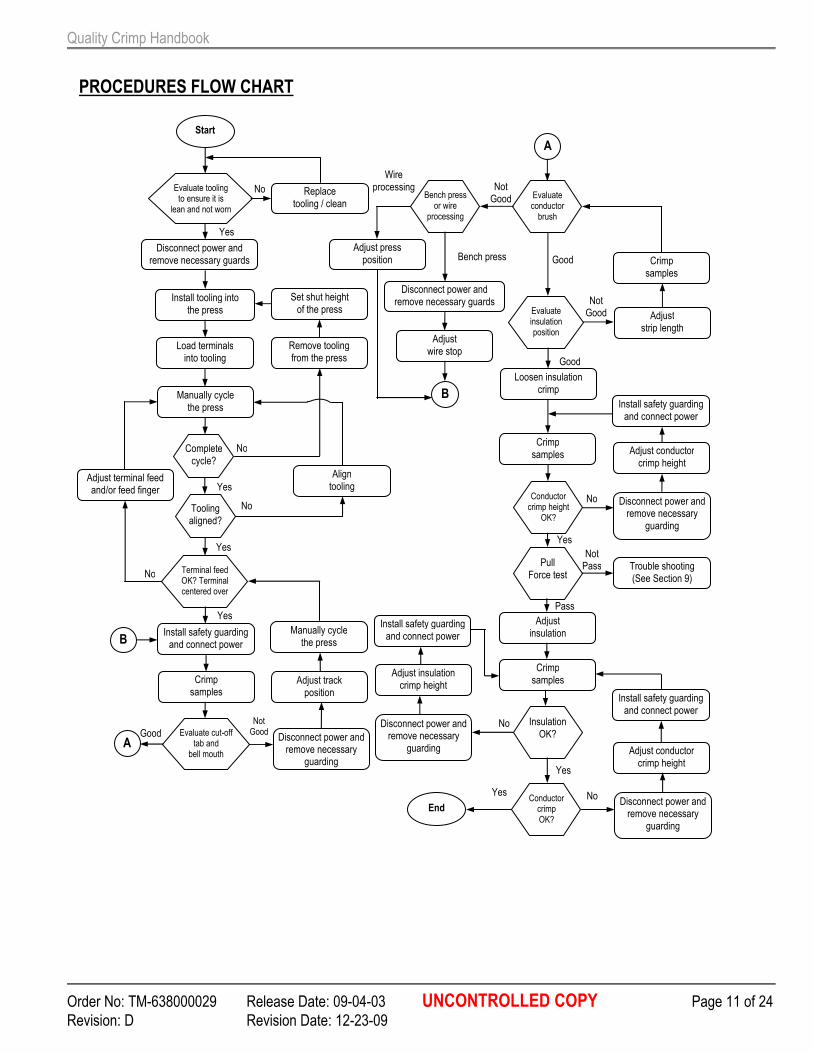
PROCEDURES Tool Setup (Reference Procedures Flow Chart) 1. Check that tooling is clean and not worn. If
necessary, clean and replace worn tooling. 2. Disconnect power to the press and remove
guarding devices. 3. Install the appropriate tooling into the press. 4. Load terminals into the tooling so that the first
terminal is located over the anvil. 5. Manually cycle the press to help ensure a complete
cycle can be made without interference. If it cannot, remove tooling and check press shut height. Go to procedure 3.
6. Check that the tooling is aligned. Check the impression on the bottom of the crimp that was made by the anvil tooling. Check that the extrusions and crimp form are centered. If not, align tooling and go to procedure 5.
7. Check that the terminal feed locates the next terminal over the center of the anvil tooling. If not, adjust terminal feed and feed finger and go to procedure 5.
8. Re-install all safety devices that were removed during the set-up. (Follow all safety requirements listed in individual press and/or tooling manuals.)
9. Crimp sample terminals under power. 10. Evaluate cut-off tab length and conductor bell
mouth. If adjustment is necessary, disconnect
power to the press and remove guarding. Adjust track position. Manually cycle the press and check the feed finger for feed location, go to procedure 7.
11. Evaluate conductor brush. If adjustment is necessary, disconnect power to the press and remove guarding. Adjust wire stop for bench applications or press position on automatic wire processing equipment. Go to procedure 8.
12. Evaluate insulation position. If necessary, adjust strip length, crimp new samples, and go to procedure 11.
13. Loosen insulation crimp height. 14. Crimp sample terminals. 15. Measure conductor crimp height and compare to
specification. If necessary, disconnect power and remove guarding. Adjust conductor crimp height, install guards, connect power, and go to procedure 14.
16. Perform a pull force test. Refer to troubleshooting (Section 9) if this test fails.
17. Adjust insulation crimp. 18. Crimp sample terminals. 19. Evaluate insulation crimp. If necessary, disconnect
power and remove guarding. Adjust insulation crimp height, install guards, connect power, and go to procedure 18.
20. Measure crimp height and compare to specification. If necessary, disconnect power and remove guarding. Adjust conductor crimp height, install guards, connect power, and go to procedure 18.
21. Document measurements.
Please Work Safely At All Times.
Quality Crimp Handbook
Order No: TM-638000029 Release Date: 09-04-03 UNCONTROLLED COPY Page 11 of 24
Revision: D Revision Date: 12-23-09
PROCEDURES FLOW CHART
Disconnect power and remove necessary guards
Install tooling into the press
Load terminals into tooling
Manually cycle the press
Evaluate tooling to ensure it is
lean and not worn
Replace tooling / clean
Set shut height of the press
Remove tooling from the press
Start
Complete cycle?
Tooling aligned?
Terminal feed OK? Terminal centered over
anvil?
Evaluate cut-off tab and bell mouth
Install safety guarding and connect power
Crimp samples
B
Adjust terminal feed and/or feed finger
Align tooling
A
Adjust track position
Manually cycle the press
Disconnect power and remove necessary
guarding
Crimp samples
Adjust press position
Evaluate conductor brush
Disconnect power and remove necessary guards
Adjust wire stop
Loosen insulation crimp
A
Bench press or wire
processing
B
Evaluate insulation position
Crimp samples
Adjust strip length
Install safety guarding and connect power
Adjust conductor crimp height
Adjust insulation
Trouble shooting (See Section 9)
Disconnect power and remove necessary
guarding
Conductor crimp height
OK?
Pull Force test
Crimp samples
Insulation OK?
Conductor crimp OK?
Install safety guarding and connect power
Adjust conductor crimp height
Disconnect power and remove necessary
guarding
Disconnect power and remove necessary
guarding
Adjust insulation crimp height
Install safety guarding and connect power
End
Wire processing
Bench press
No
No
Yes
Yes
Yes
No
No
Yes
Good
Not Good
No
No
Yes
Good
Not Pass
Yes
Pass
Good
Not Good
Not Good
No
Yes
Quality Crimp Handbook
Order No: TM-638000029 Release Date: 09-04-03 UNCONTROLLED COPY Page 12 of 24
Revision: D Revision Date: 12-23-09
SECTION 7
MEASUREMENT Pull Force Testing 1. Cut wire length to approximately 150mm (6”) long. 2. Strip one end to 13mm (.50”), or long enough so no
wire insulation is under the insulation grip, or loosen the insulation crimp so it has no grip on the insulation of the wire.
3. Terminate the appropriate terminal to the wire to the nominal crimp height.
4. Visually inspect the termination for bell mouth, wire brush and cut strands.
5. Set pull tester to 254mm per minute (1.00" per minute). For most applications, a higher rate will not have a significant impact on the data. The slower rate prevents a sudden application of force or jerking that snaps strands. Verify higher pull rates with data taken at 1.00” per minute.
6. If necessary, knot the un-terminated end of the wire (If insulation slips on wire).
7. Regardless of pull tester type, both wire and terminated end must be securely clamped. (Note: Clamp terminal contact interface, do not clamp conductor crimp)
8. Activate pull test. a. Record pull force readings. A minimum of five
pull force measurements should be done to confirm each set-up. A minimum of 25 readings should be taken for determining process capability.
b. Compare lowest reading to minimum pull force specification.
Note: High variability and lower value of Cpk (see section 8 for explanation of Cpk) are common when two wires are crimped together. The variability is due to more variation in conductor brush, conductor bell mouth and fewer strands of one wire being in contact with the serrations on the terminal barrel. A double wire crimp is considered no better than the smallest wire crimped. Higher pull force readings can be seen if both wires are gripped and pulled exactly together. Pulling each wire individually will result in a much lower pull force reading. If both wires are of the same size,
the top wire will normally result in a lower reading than the bottom wire due to the effects of the terminal serrations.
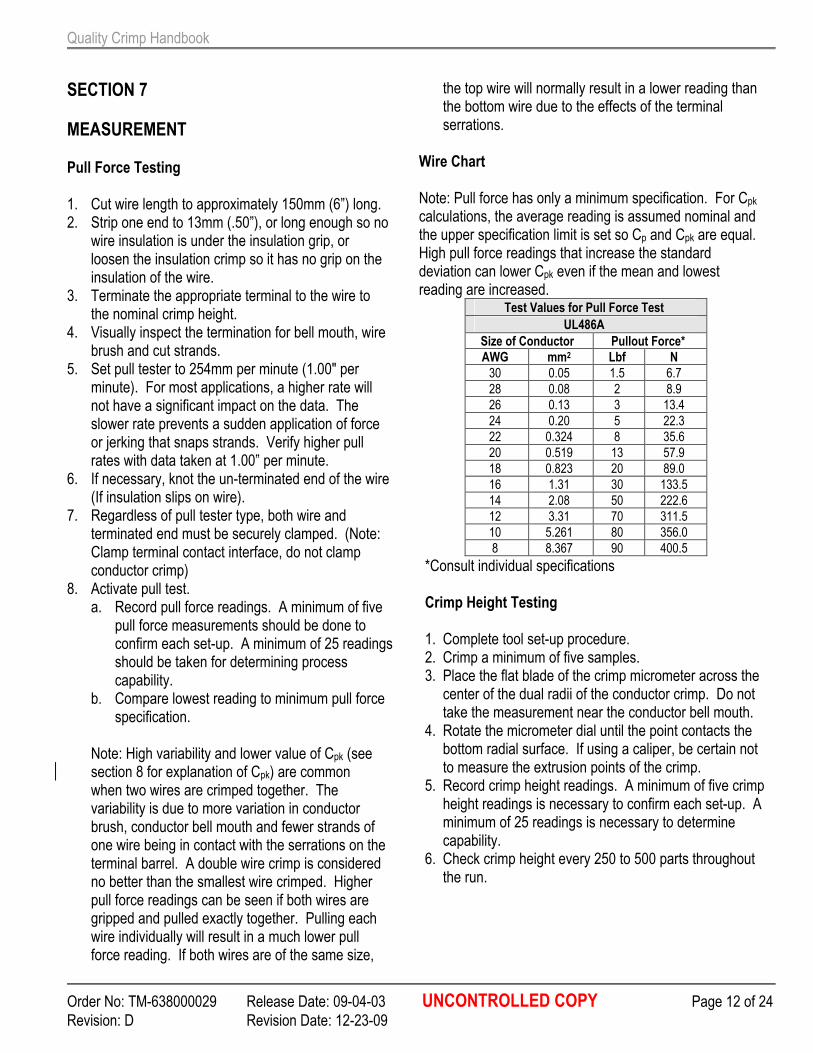
Wire Chart Note: Pull force has only a minimum specification. For Cpk calculations, the average reading is assumed nominal and the upper specification limit is set so Cp and Cpk are equal. High pull force readings that increase the standard deviation can lower Cpk even if the mean and lowest reading are increased.
Test Values for Pull Force Test
UL486A
Size of Conductor Pullout Force*
AWG mm2 Lbf N
30 0.05 1.5 6.7
28 0.08 2 8.9
26 0.13 3 13.4
24 0.20 5 22.3
22 0.324 8 35.6
20 0.519 13 57.9
18 0.823 20 89.0
16 1.31 30 133.5
14 2.08 50 222.6
12 3.31 70 311.5
10 5.261 80 356.0
8 8.367 90 400.5
*Consult individual specifications Crimp Height Testing
1. Complete tool set-up procedure. 2. Crimp a minimum of five samples. 3. Place the flat blade of the crimp micrometer across the center of the dual radii of the conductor crimp. Do not take the measurement near the conductor bell mouth.
4. Rotate the micrometer dial until the point contacts the bottom radial surface. If using a caliper, be certain not to measure the extrusion points of the crimp.
5. Record crimp height readings. A minimum of five crimp height readings is necessary to confirm each set-up. A minimum of 25 readings is necessary to determine capability.
6. Check crimp height every 250 to 500 parts throughout the run.
Quality Crimp Handbook
Order No: TM-638000029 Release Date: 09-04-03 UNCONTROLLED COPY Page 13 of 24
Revision: D Revision Date: 12-23-09
Note: Crimp height is usually control charted because it is a quick, nondestructive measurement and is critical for the termination's electrical and mechanical reliability. There are three primary purposes for control charting. One, the number of setup samples is normally small, and its statistical value is limited. Two, since special cause/effects on a process are irregular and unpredictable; it is necessary to have a means of catching changes in the process as soon as they occur. This prevents having to scrap thousands of terminations after the run is over. Three and this is most important, the data is necessary to assess and improve the crimp process.
Quality Crimping Handbook
Order No 63800-0029 Release Date: 09-04-03 UNCONTROLLED COPY Page 14 of 24
Revision: A Revision Date: 09-04-03
Figure 7-3 CALIPER Figure 7-2
CRIMP MICROMETER
Figure 7-1 PULL TESTING
Quality Crimp Handbook
Order No: TM-638000029 Release Date: 09-04-03 UNCONTROLLED COPY Page 15 of 24
Revision: D Revision Date: 12-23-09
SECTION 8
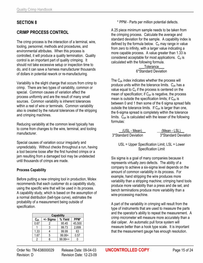
CRIMP PROCESS CONTROL The crimp process is the interaction of a terminal, wire, tooling, personnel, methods and procedures, and environmental attributes. When this process is controlled, it will produce a quality termination. Quality control is an important part of quality crimping. It should not take excessive setup or inspection time to do, and it can save a harness manufacturer thousands of dollars in potential rework or re-manufacturing. Variability is the slight change that occurs from crimp to crimp. There are two types of variability, common or special. Common causes of variation affect the process uniformly and are the result of many small sources. Common variability is inherent tolerances within a reel of wire or terminals. Common variability also is created by the natural tolerances of the stripping and crimping machines. Reducing variability at the common level typically has to come from changes to the wire, terminal, and tooling manufacturer. Special causes of variation occur irregularly and unpredictably. Without checks throughout a run, having a tool become loose after the first hundred crimps or a jam resulting from a damaged tool may be undetected until thousands of crimps are made. Process Capability
Before putting a new crimping tool in production, Molex recommends that each customer do a capability study, using the specific wire that will be used in its process. A capability study, which is based on the assumption of a normal distribution (bell-type curve), estimates the probability of a measurement being outside of specification.
Capability
Cpk +/- Sigma % Yield PPM*
0.67 2 95.45 45,500
1 3 99.73 2,699
1.33 4 99.99 63
1.67 5 99.99+ 0.57
2 6 99.99++ 0
* PPM - Parts per million potential defects.
A 25 piece minimum sample needs to be taken from the crimping process. Calculate the average and standard deviation for the sample. A capability index is defined by the formula below. Cp may range in value from zero to infinity, with a larger value indicating a more capable process. A value greater than 1.33 is considered acceptable for most applications. Cp is calculated with the following formula.
___Tolerance___ 6*Standard Deviation
The Cpk index indicates whether the process will produce units within the tolerance limits. Cpk has a value equal to Cp if the process is centered on the mean of specification; if Cpk is negative, the process mean is outside the specification limits; if Cpk is between 0 and 1 then some of the 6 sigma spread falls outside the tolerance limits. If Cpk is larger than one, the 6-sigma spread is completely within the tolerance limits. Cpk is calculated with the lesser of the following formulas:
__(USL - Mean)__ __ (Mean - LSL)__ 3*Standard Deviation 3*Standard Deviation
USL = Upper Specification Limit, LSL = Lower
Specification Limit Six sigma is a goal of many companies because it represents virtually zero defects. The ability of a company to achieve a six-sigma level depends on the amount of common variability in its process. For example, hand stripping the wire produces more variability than a stripping machine; crimping hand tools produce more variability than a press and die set, and bench terminations produce more variability than a wire-processing machine. A part of the variability in crimping will result from the type of instruments that are used to measure the parts and the operator's ability to repeat the measurement. A crimp micrometer will measure more accurately than a dial caliper. An automatic pull force system will measure better than a hook type scale. It is important that the measurement gauge has enough resolution.
Quality Crimp Handbook
Order No: TM-638000029 Release Date: 09-04-03 UNCONTROLLED COPY Page 16 of 24
Revision: D Revision Date: 12-23-09
Two operators may measure the same part differently, or the same operator may measure the part differently when using two types of gauges. Molex recommends a gauge capability study to identify what part of the variability is coming from measurement error. Micro-terminals crimped to small wire sizes need a tight crimp height range to maintain pull force. The variability from measurement error can keep Cpk values low.
The capability of the crimping tools needs to be re-confirmed if the production data is significantly different from the capability study. Production Before the tool is ready for production, the level of capability needs to be established. Many harness manufacturers run only a few hundred or few thousand wires at one time. In this case, it is not practical or economical to run a twenty-five-piece capability with every set-up. Visual Inspection It needs to be standard operating procedure for the operator to manually fan each bundle of crimped wires and visually check bell mouth, conductor brush, insulation position, cut-off tab length, and insulation crimp. Control Charting Crimp height is typically control charted because it is a quick nondestructive measurement and is critical for the termination's electrical and mechanical reliability. There are three primary purposes for control charting. One, the number of setup samples is usually small, with limited statistical value. Two, since special cause effects on a process are irregular and unpredictable; it is necessary to be able to catch changes in the process as soon as they occur. This prevents thousands of terminations from being scrapped after the run is over. Three, and most important, this data is necessary to assess and improve the crimp process. Once the tooling process is setup and the wire size does not change, keep one control chart for wire color changes, wire length changes, terminal material
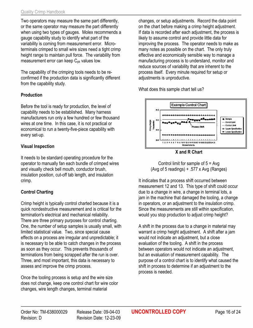
changes, or setup adjustments. Record the data point on the chart before making a crimp height adjustment. If data is recorded after each adjustment, the process is likely to assume control and provide little data for improving the process. The operator needs to make as many notes as possible on the chart. The only truly effective and economically sensible way to manage a manufacturing process is to understand, monitor and reduce sources of variability that are inherent to the process itself. Every minute required for setup or adjustments is unproductive. What does this sample chart tell us?
X and R Chart
Control limit for sample of 5 = Avg (Avg of 5 readings) + .577 x Avg (Ranges)
It indicates that a process shift occurred between measurement 12 and 13. This type of shift could occur due to a change in wire, a change in terminal lots, a jam in the machine that damaged the tooling, a change in operators, or an adjustment to the insulation crimp. Since the measurements are still within specification, would you stop production to adjust crimp height? A shift in the process due to a change in material may warrant a crimp height adjustment. A shift after a jam would not indicate an adjustment, but a close evaluation of the tooling. A shift in the process between operators would not indicate an adjustment, but an evaluation of measurement capability. The purpose of a control chart is to identify what caused the shift in process to determine if an adjustment to the process is needed.
Quality Crimp Handbook
Order No: TM-638000029 Release Date: 09-04-03 UNCONTROLLED COPY Page 17 of 24
Revision: D Revision Date: 12-23-09
SECTION 9
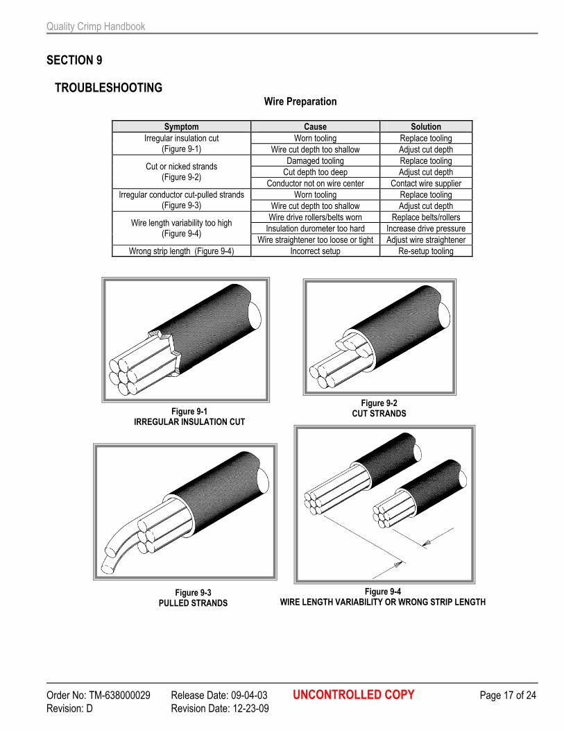
TROUBLESHOOTING Wire Preparation
Symptom Cause Solution
Worn tooling Replace tooling Irregular insulation cut (Figure 9-1) Wire cut depth too shallow Adjust cut depth
Damaged tooling Replace tooling
Cut depth too deep Adjust cut depth Cut or nicked strands
(Figure 9-2) Conductor not on wire center Contact wire supplier
Worn tooling Replace tooling Irregular conductor cut-pulled strands (Figure 9-3) Wire cut depth too shallow Adjust cut depth
Wire drive rollers/belts worn Replace belts/rollers
Insulation durometer too hard Increase drive pressure Wire length variability too high
(Figure 9-4) Wire straightener too loose or tight Adjust wire straightener
Wrong strip length (Figure 9-4) Incorrect setup Re-setup tooling
Figure 9-1 IRREGULAR INSULATION CUT
Figure 9-2 CUT STRANDS
Figure 9-3 PULLED STRANDS
Figure 9-4 WIRE LENGTH VARIABILITY OR WRONG STRIP LENGTH
Quality Crimp Handbook
Order No: TM-638000029 Release Date: 09-04-03 UNCONTROLLED COPY Page 18 of 24
Revision: D Revision Date: 12-23-09
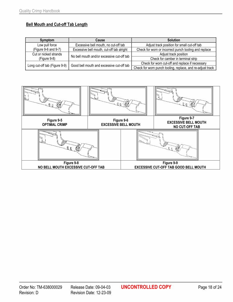
Bell Mouth and Cut-off Tab Length
Symptom Cause Solution
Excessive bell mouth, no cut-off tab Adjust track position for small cut-off tab Low pull force (Figure 9-6 and 9-7) Excessive bell mouth, cut-off tab alright Check for worn or incorrect punch tooling and replace
Adjust track position Cut or nicked strands (Figure 9-8)
No bell mouth and/or excessive cut-off tab Check for camber in terminal strip
Check for worn cut-off and replace if necessary Long cut-off tab (Figure 9-9) Good bell mouth and excessive cut-off tab
Check for worn punch tooling, replace, and re-adjust track
Figure 9-5 OPTIMAL CRIMP
Figure 9-6 EXCESSIVE BELL MOUTH
Figure 9-7 EXCESSIVE BELL MOUTH
NO CUT-OFF TAB
Figure 9-8
NO BELL MOUTH EXCESSIVE CUT-OFF TAB Figure 9-9
EXCESSIVE CUT-OFF TAB GOOD BELL MOUTH
Quality Crimp Handbook
Order No: TM-638000029 Release Date: 09-04-03 UNCONTROLLED COPY Page 19 of 24
Revision: D Revision Date: 12-23-09
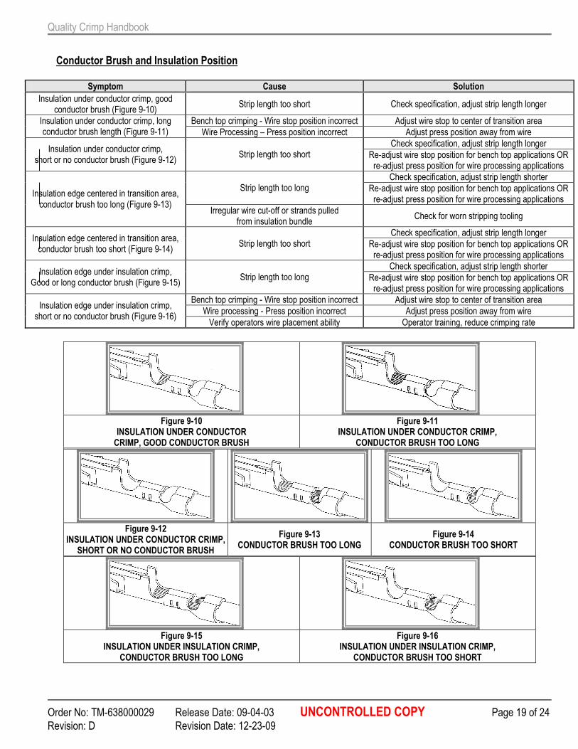
Conductor Brush and Insulation Position
Symptom Cause Solution
Insulation under conductor crimp, good conductor brush (Figure 9-10)
Strip length too short Check specification, adjust strip length longer
Bench top crimping - Wire stop position incorrect Adjust wire stop to center of transition area Insulation under conductor crimp, long conductor brush length (Figure 9-11) Wire Processing – Press position incorrect Adjust press position away from wire
Check specification, adjust strip length longer Insulation under conductor crimp,
short or no conductor brush (Figure 9-12) Strip length too short Re-adjust wire stop position for bench top applications OR
re-adjust press position for wire processing applications
Check specification, adjust strip length shorter Strip length too long Re-adjust wire stop position for bench top applications OR
re-adjust press position for wire processing applications Insulation edge centered in transition area, conductor brush too long (Figure 9-13)
Irregular wire cut-off or strands pulled from insulation bundle
Check for worn stripping tooling
Check specification, adjust strip length longer Insulation edge centered in transition area, conductor brush too short (Figure 9-14)
Strip length too short Re-adjust wire stop position for bench top applications OR re-adjust press position for wire processing applications
Check specification, adjust strip length shorter Insulation edge under insulation crimp,
Good or long conductor brush (Figure 9-15) Strip length too long Re-adjust wire stop position for bench top applications OR
re-adjust press position for wire processing applications
Bench top crimping - Wire stop position incorrect Adjust wire stop to center of transition area
Wire processing - Press position incorrect Adjust press position away from wire Insulation edge under insulation crimp, short or no conductor brush (Figure 9-16)
Verify operators wire placement ability Operator training, reduce crimping rate
Figure 9-10
INSULATION UNDER CONDUCTOR CRIMP, GOOD CONDUCTOR BRUSH
Figure 9-11 INSULATION UNDER CONDUCTOR CRIMP,
CONDUCTOR BRUSH TOO LONG
Figure 9-12
INSULATION UNDER CONDUCTOR CRIMP, SHORT OR NO CONDUCTOR BRUSH
Figure 9-13 CONDUCTOR BRUSH TOO LONG
Figure 9-14 CONDUCTOR BRUSH TOO SHORT
Figure 9-15
INSULATION UNDER INSULATION CRIMP, CONDUCTOR BRUSH TOO LONG
Figure 9-16 INSULATION UNDER INSULATION CRIMP,
CONDUCTOR BRUSH TOO SHORT
Quality Crimp Handbook
Order No: TM-638000029 Release Date: 09-04-03 UNCONTROLLED COPY Page 20 of 24
Revision: D Revision Date: 12-23-09
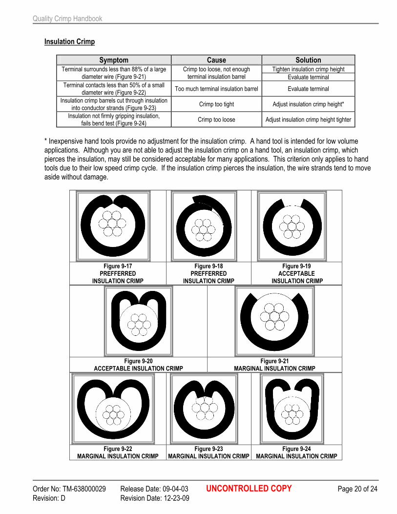
Insulation Crimp
Symptom Cause Solution Tighten insulation crimp height Terminal surrounds less than 88% of a large
diameter wire (Figure 9-21) Crimp too loose, not enough terminal insulation barrel Evaluate terminal
Terminal contacts less than 50% of a small diameter wire (Figure 9-22)
Too much terminal insulation barrel Evaluate terminal
Insulation crimp barrels cut through insulation into conductor strands (Figure 9-23)
Crimp too tight Adjust insulation crimp height*
Insulation not firmly gripping insulation, fails bend test (Figure 9-24)
Crimp too loose Adjust insulation crimp height tighter
* Inexpensive hand tools provide no adjustment for the insulation crimp. A hand tool is intended for low volume applications. Although you are not able to adjust the insulation crimp on a hand tool, an insulation crimp, which pierces the insulation, may still be considered acceptable for many applications. This criterion only applies to hand tools due to their low speed crimp cycle. If the insulation crimp pierces the insulation, the wire strands tend to move aside without damage.
Figure 9-17
PREFFERRED INSULATION CRIMP
Figure 9-18 PREFFERRED
INSULATION CRIMP
Figure 9-19 ACCEPTABLE
INSULATION CRIMP
Figure 9-20
ACCEPTABLE INSULATION CRIMP Figure 9-21
MARGINAL INSULATION CRIMP
Figure 9-22
MARGINAL INSULATION CRIMP Figure 9-23
MARGINAL INSULATION CRIMP Figure 9-24
MARGINAL INSULATION CRIMP
Quality Crimp Handbook
Order No: TM-638000029 Release Date: 09-04-03 UNCONTROLLED COPY Page 21 of 24
Revision: D Revision Date: 12-23-09
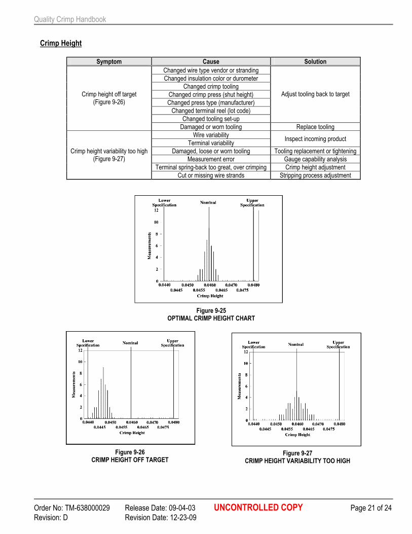
Figure 9-25 OPTIMAL CRIMP HEIGHT CHART
Figure 9-26 CRIMP HEIGHT OFF TARGET
Figure 9-27 CRIMP HEIGHT VARIABILITY TOO HIGH
Crimp Height
Symptom Cause Solution
Changed wire type vendor or stranding
Changed insulation color or durometer
Changed crimp tooling
Changed crimp press (shut height)
Changed press type (manufacturer)
Changed terminal reel (lot code)
Changed tooling set-up
Adjust tooling back to target Crimp height off target (Figure 9-26)
Damaged or worn tooling Replace tooling
Wire variability
Terminal variability Inspect incoming product
Damaged, loose or worn tooling Tooling replacement or tightening
Measurement error Gauge capability analysis
Terminal spring-back too great, over crimping Crimp height adjustment
Crimp height variability too high (Figure 9-27)
Cut or missing wire strands Stripping process adjustment
Quality Crimp Handbook
Order No: TM-638000029 Release Date: 09-04-03 UNCONTROLLED COPY Page 22 of 24
Revision: D Revision Date: 12-23-09
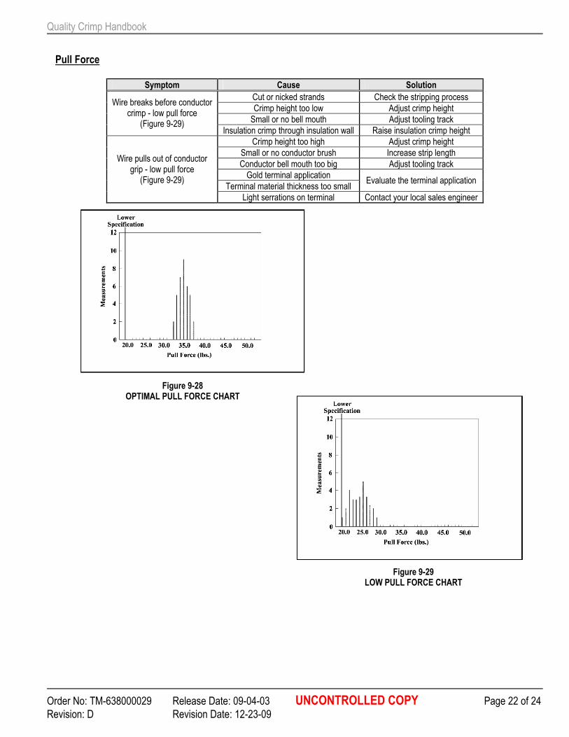
Pull Force
Symptom Cause Solution
Cut or nicked strands Check the stripping process
Crimp height too low Adjust crimp height
Small or no bell mouth Adjust tooling track
Wire breaks before conductor crimp - low pull force
(Figure 9-29) Insulation crimp through insulation wall Raise insulation crimp height
Crimp height too high Adjust crimp height
Small or no conductor brush Increase strip length
Conductor bell mouth too big Adjust tooling track
Gold terminal application
Terminal material thickness too small Evaluate the terminal application
Wire pulls out of conductor grip - low pull force (Figure 9-29)
Light serrations on terminal Contact your local sales engineer
Figure 9-28 OPTIMAL PULL FORCE CHART
Figure 9-29 LOW PULL FORCE CHART
Quality Crimp Handbook
Order No: TM-638000029 Release Date: 09-04-03 UNCONTROLLED COPY Page 23 of 24
Revision: D Revision Date: 12-23-09
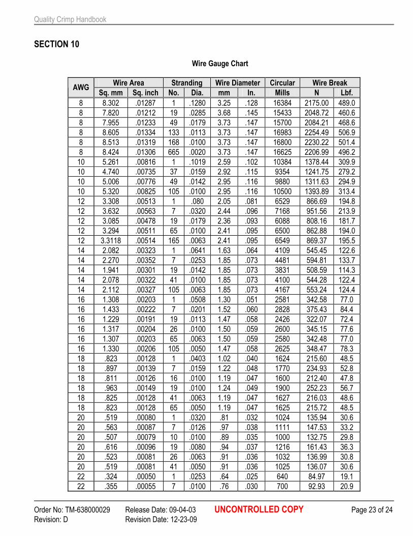
SECTION 10
Wire Gauge Chart
Wire Area Stranding Wire Diameter Circular Wire Break AWG
Sq. mm Sq. inch No. Dia. mm In. Mills N Lbf.
8 8.302 .01287 1 .1280 3.25 .128 16384 2175.00 489.0
8 7.820 .01212 19 .0285 3.68 .145 15433 2048.72 460.6
8 7.955 .01233 49 .0179 3.73 .147 15700 2084.21 468.6
8 8.605 .01334 133 .0113 3.73 .147 16983 2254.49 506.9
8 8.513 .01319 168 .0100 3.73 .147 16800 2230.22 501.4
8 8.424 .01306 665 .0020 3.73 .147 16625 2206.99 496.2
10 5.261 .00816 1 .1019 2.59 .102 10384 1378.44 309.9
10 4.740 .00735 37 .0159 2.92 .115 9354 1241.75 279.2
10 5.006 .00776 49 .0142 2.95 .116 9880 1311.63 294.9
10 5.320 .00825 105 .0100 2.95 .116 10500 1393.89 313.4
12 3.308 .00513 1 .080 2.05 .081 6529 866.69 194.8
12 3.632 .00563 7 .0320 2.44 .096 7168 951.56 213.9
12 3.085 .00478 19 .0179 2.36 .093 6088 808.16 181.7
12 3.294 .00511 65 .0100 2.41 .095 6500 862.88 194.0
12 3.3118 .00514 165 .0063 2.41 .095 6549 869.37 195.5
14 2.082 .00323 1 .0641 1.63 .064 4109 545.45 122.6
14 2.270 .00352 7 .0253 1.85 .073 4481 594.81 133.7
14 1.941 .00301 19 .0142 1.85 .073 3831 508.59 114.3
14 2.078 .00322 41 .0100 1.85 .073 4100 544.28 122.4
14 2.112 .00327 105 .0063 1.85 .073 4167 553.24 124.4
16 1.308 .00203 1 .0508 1.30 .051 2581 342.58 77.0
16 1.433 .00222 7 .0201 1.52 .060 2828 375.43 84.4
16 1.229 .00191 19 .0113 1.47 .058 2426 322.07 72.4
16 1.317 .00204 26 .0100 1.50 .059 2600 345.15 77.6
16 1.307 .00203 65 .0063 1.50 .059 2580 342.48 77.0
16 1.330 .00206 105 .0050 1.47 .058 2625 348.47 78.3
18 .823 .00128 1 .0403 1.02 .040 1624 215.60 48.5
18 .897 .00139 7 .0159 1.22 .048 1770 234.93 52.8
18 .811 .00126 16 .0100 1.19 .047 1600 212.40 47.8
18 .963 .00149 19 .0100 1.24 .049 1900 252.23 56.7
18 .825 .00128 41 .0063 1.19 .047 1627 216.03 48.6
18 .823 .00128 65 .0050 1.19 .047 1625 215.72 48.5
20 .519 .00080 1 .0320 .81 .032 1024 135.94 30.6
20 .563 .00087 7 .0126 .97 .038 1111 147.53 33.2
20 .507 .00079 10 .0100 .89 .035 1000 132.75 29.8
20 .616 .00096 19 .0080 .94 .037 1216 161.43 36.3
20 .523 .00081 26 .0063 .91 .036 1032 136.99 30.8
20 .519 .00081 41 .0050 .91 .036 1025 136.07 30.6
22 .324 .00050 1 .0253 .64 .025 640 84.97 19.1
22 .355 .00055 7 .0100 .76 .030 700 92.93 20.9
Quality Crimp Handbook
Order No: TM-638000029 Release Date: 09-04-03 UNCONTROLLED COPY Page 24 of 24
Revision: D Revision Date: 12-23-09
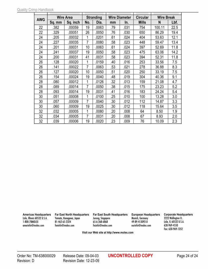
Wire Area Stranding Wire Diameter Circular Wire Break AWG
Sq. mm Sq. inch No. Dia. mm In. Mills N Lbf.
22 .382 .00059 19 .0063 .79 .031 754 100.11 22.5
22 .329 .00051 26 .0050 .76 .030 650 86.29 19.4
24 .205 .00032 1 .0201 .61 .024 404 53.63 12.1
24 .227 .00035 7 .0080 .58 .023 448 59.47 13.4
24 .201 .00031 10 .0063 .61 .024 397 52.69 11.8
24 .241 .00037 19 .0050 .58 .023 475 63.06 14.2
24 .200 .00031 41 .0031 .58 .023 394 52.31 11.8
26 .128 .00020 1 .0159 .40 .016 253 33.56 7.5
26 .141 .00022 7 .0063 .53 .021 278 36.88 8.3
26 .127 .00020 10 .0050 .51 .020 250 33.19 7.5
26 .154 .00024 19 .0040 .48 .019 304 40.36 9.1
28 .080 .00012 1 .0126 .32 .013 159 21.08 4.7
28 .089 .00014 7 .0050 .38 .015 175 23.23 5.2
28 .093 .00014 19 .0031 .41 .016 183 24.24 5.4
30 .051 .00008 1 .0100 .25 .010 100 13.28 3.0
30 .057 .00009 7 .0040 .30 .012 112 14.87 3.3
30 .060 .00009 19 .0025 .30 .012 118 15.64 3.5
32 .032 .00005 1 .0080 .20 .008 64 8.50 1.9
32 .034 .00005 7 .0031 .20 .008 67 8.93 2.0
32 .039 .00006 19 .0020 .23 .009 76 10.09 2.3
Americas Headquarters
Lisle, Illinois 60532 U.S.A. 1-800-78MOLEX [email protected]
Far East North Headquarters
Yamato, Kanagawa, Japan 81-462-65-2324 [email protected]
Far East South Headquarters
Jurong, Singapore 65-6-268-6868 [email protected]
European Headquarters
Munich, Germany 49-89-413092-0 [email protected]
Corporate Headquarters
2222 Wellington Ct. Lisle, IL 60532 U.S.A. 630-969-4550 Fax: 630-969-1352
Visit our Web site at http://www.molex.com