Embed Size (px)
Citation preview
quality handbookHandbook of production tolerances and the visual assessment of glass products3rd edition 2020/5

contents
1. Foreword 4
physical characteristics
2. Basic glass 5
2.1 Glass thickness 5
3. Processed glass, single pane 5
3.1 Definitionedgetypes 6
3.2 Dimensions 7
3.3 Drill-holes and cut-outs 7
3.4 Tolerances for thermally treated glass
(heat-strengthened, fully tempered,
heat-soaked fully tempered and others) 8
3.5 Tolerances of bent glass 9
4. Laminated glass 10
4.1 Dimensions 10
4.2 Edge offset 10
4.3 Thickness tolerance 10
4.4 Bent glass 10
5. Insulating glass 11
5.1 Thickness tolerance of insulating glass 11
5.2 Offset of the edge seal 11
5.3 Flatness of the glass panes 11
5.4 Spacer 11
5.5 Glass spacer 11
5.5 Butyl sealing 11
5.6 Edgeseal 12
5.7 Glass coatings 12
visual characteristics
6. Assessment of the visual quality
of single glass panes and glass laminates 13
6.1 Sphereofvalidity 13
6.2 Inspection 13
6.2.1Assessmentofthevisualquality 14
6.2.2Assessmentoftemperedglass 15
6.2.3Assessmentofglassedges 15
7. Assessment of the visual quality
of printed glass 16
7.1 Sphereofvalidity 16
7.2 Installationareas 16
7.3 Inspectionofprintedglass 16
7.3.1 Assessmentofcolortransitionsand
color deviations 18
7.4 Production technology of printing glass 19
7.4.1 Roller application technology 19
7.4.2 Digital printing technology 19
7.4.3 Thermal treatment 19
7.4.4 Laminated glass 19
4
1 foreword
This handbook serves as a basis for the assessment of products manufacturedandsoldbysedakGmbH&Co.KG.Itsupple-mentsagreed tolerancessubject toorderspecificationsandprovides a basis if such agreed tolerances do not exist. This tolerance handbook is based on the here mentioned stand-ards, regulations and data sheets as well as the latest state of technology. Unless otherwise agreed, the state of the under-lying document at the time of the offer is valid. Should some parts of the handbook have been replaced by order-specificarrangements, the residual content remains in force.
This handbook constitutes part of the latest version of our General terms and Conditions. By accepting them you also accept our handbook.
Ifvaluesordimensionsarenotspecifiedhereorshouldindi-cated objects for comparison be exceeded, they are treated as notdefinedandaretobeagreedwhenanorderisplaced.
ThestatedvaluesrefertofloatglassaccordingtoDINEN572for low-iron glass. For different glass types, the values must be arranged.
Shouldvaluesor testmethodsnotbedefinedby thishand-book, the versions of the mentioned standards, regulations, datasheetsandreferencesarevalid.Ifacertainfeatureisstillnotdefinedorcharacterized, thefeature isdeemedasnot definedandhastobearrangedbeforeanorderisplaced.
sedakGmbH&Co.KGiscertifiedaccordingtoISO9001:2015.Ourcertificatecanbedownloadedonourwebsite.
The latest version is only guaranteed by obtaining it by sedak GmbH & Co. KG. Please download the latest version on www.sedak.com or contact your sales contact person at sedak GmbH & Co. KG. They will also be pleased to be at your disposalforquestionsandcomments.
5
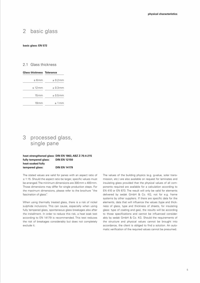
2 basic glass
basic glass: EN 572
2.1 Glass thickness
Glass thickness Tolerance
≤6mm ± 0.2 mm
≤12mm ± 0.3 mm
15 mm ± 0.5 mm
19 mm ± 1 mm
3 processed glass, single pane
heat strengthened glass: DIN EN 1863, ABZ Z-70.4-215fully tempered glass: DIN EN 12150heat-soaked fully tempered glass: DIN EN 14179
The stated values are valid for panes with an aspect ratio of ≤1:15.Shouldtheaspectratiobelarger,specificvaluesmustbe arranged. The minimum dimensions are 300 mm x 400 mm. Those dimensions may differ for single production steps. For the maximum dimensions, please refer to the brochure “the fascination of glass”.
When using thermally treated glass, there is a risk of nickel sulphide inclusions. This can cause, especially when using fully tempered glass, spontaneous glass breakages also after theinstallment.Inordertoreducethisrisk,aheatsoaktestaccordingtoEN14179 is recommended.This test reduces the risk of breakages considerably but does not completely exclude it.
The values of the building physics (e.g. g-value, solar trans-mission,etc.)arealsoavailableonrequestforlaminatesandinsulating glass provided that the physical values of all com-ponents required are available for a calculation according toEN410orEN673.Theresultwillonlybevalidforelementsdelivered by sedak GmbH & Co. KG, not for e.g. frame systemsbyothersuppliers. Iftherearespecificdatafortheelements,datathatwill influencethevalues(typeandthick-ness of glass, type and thickness of sheets, for insulating glass:typeofcoatingandgas),theresultswillbeaccordingto those specifications and cannot be influenced consider- ablybysedakGmbH&Co.KG.Should the requirementsof the structure and physical values cannot be brought into accordance, theclient isobliged tofindasolution.Anauto-maticverificationoftherequiredvaluescannotbepresumed.
physical characteristics
6
top view
Glasdicke
1000 mm
B
V V
B bzw H
top view
a
b
c 3500 mm
300 mm
3500 mm
300 mm
S
45
S
D+-tdi
45 45
90
2b
6b P
2b
d
B
PK
PG
PB
PV
PC
PC
t1t2
t3
t4B – t
B + t
top view
H –
t
H +
t
2a
ax
B bzw H 300 mm
B, H V i
i i
PSS +
DMin
Randzone (R)
Falzzone (F)
Hauptzone Breite
Lichte Breite (b)
Scheibenbreite
b/10 b/10
F F
Hauptzone Breite
Randzone (min. 15 mm umlaufend)
1000 mm
td
Id
2 mm
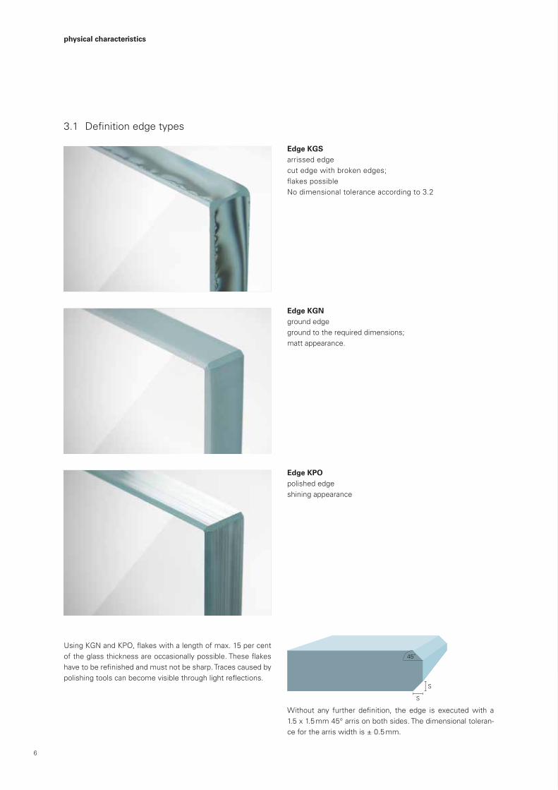
3.1 Definitionedgetypes
Edge KGSarrissed edge cut edge with broken edges;flakespossibleNodimensionaltoleranceaccordingto3.2
Edge KGN ground edge groundtotherequireddimensions;matt appearance.
Edge KPO polished edge shining appearance
physical characteristics
UsingKGNandKPO,flakeswithalengthofmax.15percentoftheglassthicknessareoccasionallypossible.Theseflakeshavetoberefinishedandmustnotbesharp.Tracescausedbypolishingtoolscanbecomevisiblethroughlightreflections.
Without any further definition, the edge is executedwith a 1.5 x 1.5 mm 45° arris on both sides. The dimensional toleran-ce for the arris width is ± 0.5 mm.
7
top view
Glasdicke
1000 mm
B
V V
B bzw H
top view
a
b
c 3500 mm
300 mm
3500 mm
300 mm
S
45
S
D+-tdi
45 45
90
2b
6b P
2b
d
B
PK
PG
PB
PV
PC
PC
t1t2
t3
t4B – t
B + t
top view
H –
t
H +
t
2a
ax
B bzw H 300 mm
B, H V i
i i
PSS +
DMin
Randzone (R)
Falzzone (F)
Hauptzone Breite
Lichte Breite (b)
Scheibenbreite
b/10 b/10
F F
Hauptzone Breite
Randzone (min. 15 mm umlaufend)
1000 mm
td
Id
2 mm
top view
Glasdicke
1000 mm
B
V V
B bzw H
top view
a
b
c 3500 mm
300 mm
3500 mm
300 mm
S
45
S
D+-tdi
45 45
90
2b
6b P
2b
d
B
PK
PG
PB
PV
PC
PC
t1t2
t3
t4B – t
B + t
top view
H –
t
H +
t
2a
ax
B bzw H 300 mm
B, H V i
i i
PSS +
DMin
Randzone (R)
Falzzone (F)
Hauptzone Breite
Lichte Breite (b)
Scheibenbreite
b/10 b/10
F F
Hauptzone Breite
Randzone (min. 15 mm umlaufend)
1000 mm
td
Id
2 mm
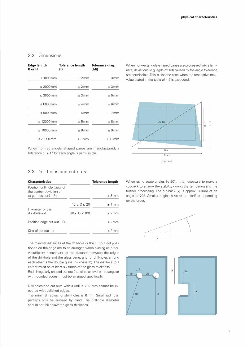
3.2 Dimensions
Edge lengthB or H
Tolerance length (t)
Tolerance diag. (tdi)
≤1000mm ± 2 mm ±3 mm
≤2000mm ± 2 mm ± 3 mm
≤3000mm ± 3 mm ± 5 mm
≤6000mm ± 4 mm ±6 mm
≤9000mm ± 4 mm ± 7 mm
≤12000 mm ± 5 mm ± 8 mm
≤16000 mm ±6 mm ± 9 mm
≤20000 mm ± 8 mm ± 11 mm
When non-rectangular-shaped panes are manufactured, a tolerance of ± 1° for each angle is permissible.
When non-rectangular-shaped panes are processed into a lami-nate, deviations (e.g. egde offset) caused by the angle tolerance are permissible. This is also the case when the respective max. value stated in the table of 4.2 is exceeded.
3.3 Drill-holes and cut-outs
Characteristics Tolerance length
Position drill-hole (view of the center, deviation of target position) – PB ± 3 mm
Diameter of the drill-hole – d
12≤Ø≤20 ± 1 mm
20<Ø≤100 ± 2 mm
Position edge cut-out – Pk ± 2 mm
Sizeofcut-out–a ± 2 mm
The minimal distances of the drill-hole or the cut-out not posi-tioned on the edge are to be arranged when placing an order. Asufficientbenchmark for thedistancebetween theedgesof the drill-hole and the glass pane, and for drill-holes among each other is the double glass thickness (b). The distance to a corner must be at least six times of the glass thickness. Each irregularly shaped cut-out (not circular, oval or rectangular withroundededges)mustbearrangedspecifically.
Drill-holes and cut-outs with a radius < 13 mm cannot be ex- ecuted with polished edges.Theminimal radius for drill-holes is 6mm. Small radii canperhaps only be arrissed by hand. The drill-hole diameter should not fall below the glass thickness.
When using acute angles (< 20°), it is necessary to make a cut-back to ensure the stability during the tempering and the further processing. The cut-back (x) is approx. 30 mm at an angle of 20°. Smaller angles have to be clarified dependingon the order.
physical characteristics
8
top
view
Gla
sdic
ke
1000
mm
B
VV
B b
zw H
top
view
ab
c35
00 m
m
300
mm
3500
mm
300
mm
S
45
S
D+
-tdi
4545
90
2b
6bP
2b
d
B
P K
P G
P B
P V
P C
P C
t 1t 2
t 3
t 4
B –
t
B +
t
top
view
H – t
H + t
2a
ax
B b
zw H
300
mm
B, H
V
i
ii
P SS
+
DM
in
Ran
dzon
e (R
)
Falz
zone
(F)
Hau
ptzo
ne B
reite
Lich
te B
reite
(b)
Sch
eibe
nbre
ite
b/10
b/10
FF
Hau
ptzo
ne B
reite
Ran
dzon
e (m
in. 1
5 m
m u
mla
ufen
d)
1000
mm
t d I d
2 m
m
top view
Glasdicke
1000 mm
B
V V
B bzw H
top view
a
b
c 3500 mm
300 mm
3500 mm
300 mm
S
45
S
D+-tdi
45 45
90
2b
6b P
2b
d
B
PK
PG
PB
PV
PC
PC
t1t2
t3
t4B – t
B + t
top view
H –
t
H +
t
2a
ax
B bzw H 300 mm
B, H V i
i i
PSS +
DMin
Randzone (R)
Falzzone (F)
Hauptzone Breite
Lichte Breite (b)
Scheibenbreite
b/10 b/10
F F
Hauptzone Breite
Randzone (min. 15 mm umlaufend)
1000 mm
td
Id
2 mm
top view
Glasdicke
1000 mm
B
V V
B bzw H
top view
a
b
c 3500 mm
300 mm
3500 mm
300 mm
S
45
S
D+-tdi
45 45
90
2b
6b P
2b
d
B
PK
PG
PB
PV
PC
PC
t1t2
t3
t4B – t
B + t
top view
H –
t
H +
t
2a
ax
B bzw H 300 mm
B, H V i
i i
PSS +
DMin
Randzone (R)
Falzzone (F)
Hauptzone Breite
Lichte Breite (b)
Scheibenbreite
b/10 b/10
F F
Hauptzone Breite
Randzone (min. 15 mm umlaufend)
1000 mm
td
Id
2 mm
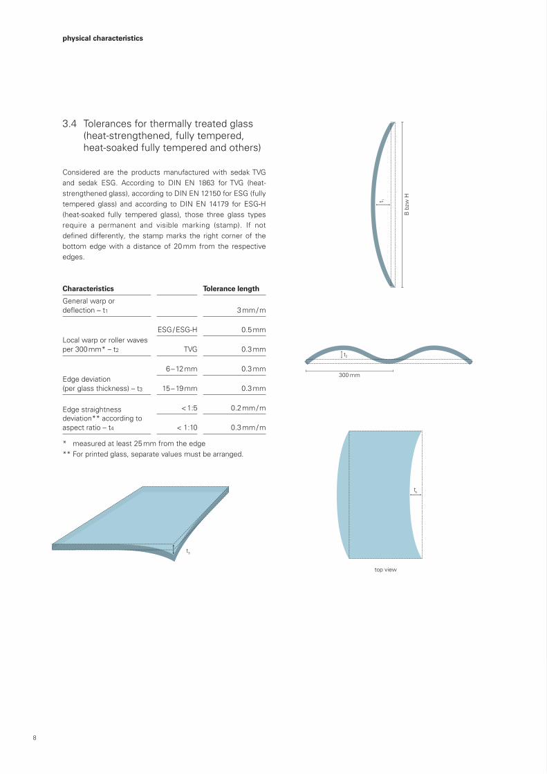
3.4 Tolerances for thermally treated glass (heat-strengthened, fully tempered, heat-soaked fully tempered and others)
Considered are the products manufactured with sedak TVG and sedak ESG. According to DIN EN 1863 forTVG (heat-strengthenedglass),accordingtoDINEN12150forESG(fullytempered glass) and according toDINEN 14179 for ESG-H(heat-soaked fully tempered glass), those three glass types require a permanent and visible marking (stamp). If not defineddifferently, the stampmarks the right corner of thebottom edge with a distance of 20 mm from the respective edges.
Characteristics Tolerance length
General warp or deflection–t1 3 mm / m
Local warp or roller waves per 300 mm* – t2
ESG / ESG-H 0.5 mm
TVG 0.3 mm
Edge deviation (per glass thickness) – t3
6–12mm 0.3 mm
15 – 19 mm 0.3 mm
Edge straightness deviation** according to aspect ratio – t4
<1:5 0.2 mm / m
<1:10 0.3 mm / m
* measured at least 25 mm from the edge** For printed glass, separate values must be arranged.
physical characteristics
9
top view
Glasdicke
1000 mm
B
V V
B bzw H
top view
a
b
c 3500 mm
300 mm
3500 mm
300 mm
S
45
S
D+-tdi
45 45
90
2b
6b P
2b
d
B
PK
PG
PB
PV
PC
PC
t1t2
t3
t4B – t
B + t
top view
H –
t
H +
t
2a
ax
B bzw H 300 mm
B, H V i
i i
PSS +
DMin
Randzone (R)
Falzzone (F)
Hauptzone Breite
Lichte Breite (b)
Scheibenbreite
b/10 b/10
F F
Hauptzone Breite
Randzone (min. 15 mm umlaufend)
1000 mm
td
Id
2 mm
top view
Glasdicke
1000 mm
B
V V
B bzw H
top view
a
b
c 3500 mm
300 mm
3500 mm
300 mm
S
45
S
D+-tdi
45 45
90
2b
6b P
2b
d
B
PK
PG
PB
PV
PC
PC
t1t2
t3
t4B – t
B + t
top view
H –
t
H +
t
2a
ax
B bzw H 300 mm
B, H V i
i i
PSS +
DMin
Randzone (R)
Falzzone (F)
Hauptzone Breite
Lichte Breite (b)
Scheibenbreite
b/10 b/10
F F
Hauptzone Breite
Randzone (min. 15 mm umlaufend)
1000 mm
td
Id
2 mm
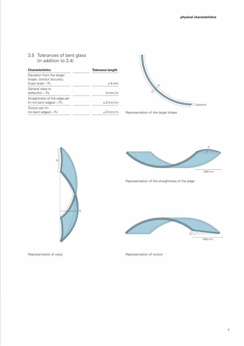
3.5 Tolerances of bent glass (in addition to 3.4)
Characteristics Tolerance length
Deviation from the target shape, contour accuracy (main area) – PC ± 4 mm
General warp or deflection–PB 4 mm / m
Straightness of the edge per lm (no bent edges) – PG ± 3 mm / m
Torsion per lm (no bent edges) – PV ± 3 mm / m
Representation of the straightness of the edge
Representation of torsionRepresentation of warp
Representation of the target shape
physical characteristics
10
top view
Glasdicke
1000 mm
B
V V
B bzw H
top view
a
b
c 3500 mm
300 mm
3500 mm
300 mm
S
45
S
D+-tdi
45 45
90
2b
6b P
2b
d
B
PK
PG
PB
PV
PC
PC
t1t2
t3
t4B – t
B + t
top view
H –
t
H +
t
2a
ax
B bzw H 300 mm
B, H V i
i i
PSS +
DMin
Randzone (R)
Falzzone (F)
Hauptzone Breite
Lichte Breite (b)
Scheibenbreite
b/10 b/10
F F
Hauptzone Breite
Randzone (min. 15 mm umlaufend)
1000 mm
td
Id
2 mm
top view
Glasdicke
1000 mm
B
V V
B bzw H
top view
a
b
c 3500 mm
300 mm
3500 mm
300 mm
S
45
S
D+-tdi
45 45
90
2b
6b P
2b
d
B
PK
PG
PB
PV
PC
PC
t1t2
t3
t4B – t
B + t
top view
H –
t
H +
t
2a
ax
B bzw H 300 mm
B, H V i
i i
PSS +
DMin
Randzone (R)
Falzzone (F)
Hauptzone Breite
Lichte Breite (b)
Scheibenbreite
b/10 b/10
F F
Hauptzone Breite
Randzone (min. 15 mm umlaufend)
1000 mm
td
Id
2 mm
physical characteristics
4 laminated glass
Laminated glass: DIN EN 12543, DIN EN 14449GlasCobond®: ABZ Z-70.3-153, Z-70.3-175
This chapter refers to the products sedak VSG, sedak secusun®, sedak secusound®, sedak secuprotect®, sedak secucolor®, sedak secudecor®, sedak clear-edge, GlasCobond®, GLY-Mari-neCobond® and all further laminates being manufactured with
usual lamination sheets (SentryGlas®, PVB, EVA, etc.).Thischapter does not apply to units laminated with e.g. casting resin or being UV-bonded.
4.1 Dimensions(total dimensions of the laminated element)
Edge length Tolerance length (tL) Tolerance diag. (tD)
≤1000mm ± 2.5 mm ± 3 mm
≤2000mm ± 3 mm ± 5 mm
≤3000mm ± 4 mm ± 7 mm
≤6000mm ±6mm ± 8 mm
≤9000mm ±6mm ± 9 mm
≤12000 mm ± 8 mm ± 11 mm
≤16000mm ± 9 mm ± 13 mm
≤20000 mm ± 10 mm ± 15 mm
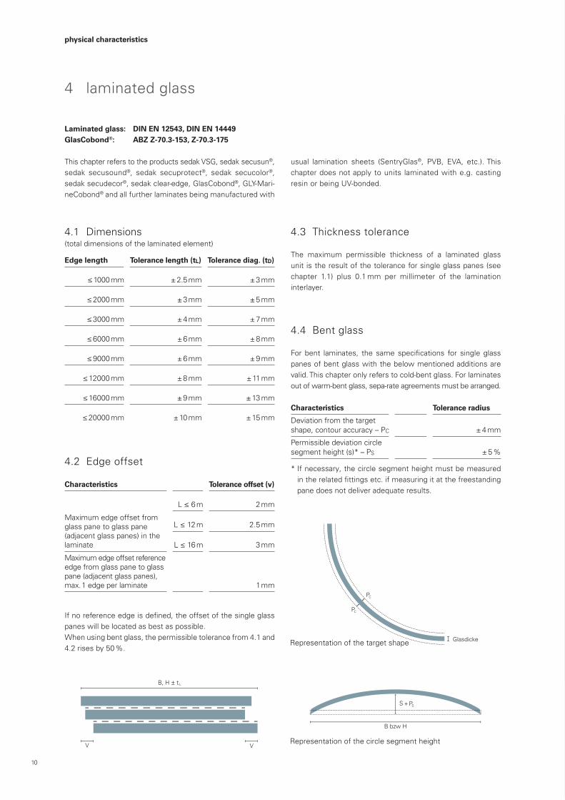
4.2 Edge offset
Characteristics Tolerance offset (v)
Maximum edge offset from glass pane to glass pane (adjacent glass panes) in the laminate
L≤6m 2 mm
L≤12m 2.5 mm
L≤16m 3 mm
Maximum edge offset reference edge from glass pane to glass pane (adjacent glass panes), max. 1 edge per laminate 1 mm
Ifnoreferenceedgeisdefined,theoffsetofthesingleglasspanes will be located as best as possible.When using bent glass, the permissible tolerance from 4.1 and 4.2 rises by 50 %.
4.3 Thickness tolerance
The maximum permissible thickness of a laminated glass unit is the result of the tolerance for single glass panes (see chapter 1.1) plus 0.1 mm per millimeter of the lamination interlayer.
4.4 Bent glass
For bent laminates, the same specifications for single glasspanes of bent glass with the below mentioned additions are valid. This chapter only refers to cold-bent glass. For laminates out of warm-bent glass, sepa-rate agreements must be arranged.
Characteristics Tolerance radius
Deviation from the target shape, contour accuracy – PC ± 4 mm
Permissible deviation circle segment height (s)* – PS ± 5 %
*Ifnecessary,thecirclesegmentheightmustbemeasuredintherelatedfittingsetc.ifmeasuringitatthefreestandingpanedoesnotdeliveradequateresults.
Representation of the target shape
Representation of the circle segment height
11
top view
Glasdicke
1000 mm
B
V V
B bzw H
top view
a
b
c 3500 mm
300 mm
3500 mm
300 mm
S
45
S
D+-tdi
45 45
90
2b
6b P
2b
d
B
PK
PG
PB
PV
PC
PC
t1t2
t3
t4B – t
B + t
top view
H –
t
H +
t
2a
ax
B bzw H 300 mm
B, H V i
i i
PSS +
DMin
Randzone (R)
Falzzone (F)
Hauptzone Breite
Lichte Breite (b)
Scheibenbreite
b/10 b/10
F F
Hauptzone Breite
Randzone (min. 15 mm umlaufend)
1000 mm
td
Id
2 mm
top view
Glasdicke
1000 mm
B
V V
B bzw H
top view
a
b
c 3500 mm
300 mm
3500 mm
300 mm
S
45
S
D+-tdi
45 45
90
2b
6b P
2b
d
B
PK
PG
PB
PV
PC
PC
t1t2
t3
t4B – t
B + t
top view
H –
t
H +
t
2a
ax
B bzw H 300 mm
B, H V i
i i
PSS +
DMin
Randzone (R)
Falzzone (F)
Hauptzone Breite
Lichte Breite (b)
Scheibenbreite
b/10 b/10
F F
Hauptzone Breite
Randzone (min. 15 mm umlaufend)
1000 mm
td
Id
2 mm
physical characteristics
5 insulating glass
Insulating glass: DIN EN 1279, Hadamar Guidline (BF-Bulletin 006-2009)
This chapter refers to the products sedak isotherm®, sedak isosun®, sedak isosound®, sedak isosecure®, sedak isocolor®, sedak isodecor®, sedak isopure® and those insulating glass products that are manufactured with a gas-proof spacer.
5.1 Thickness tolerance of insulating glass
The permissible total thickness is the result of the single tolerances (see chapters 1.1 and 3.3) plus ± 0.1 mm per 1 mm thickness of the edge seal.
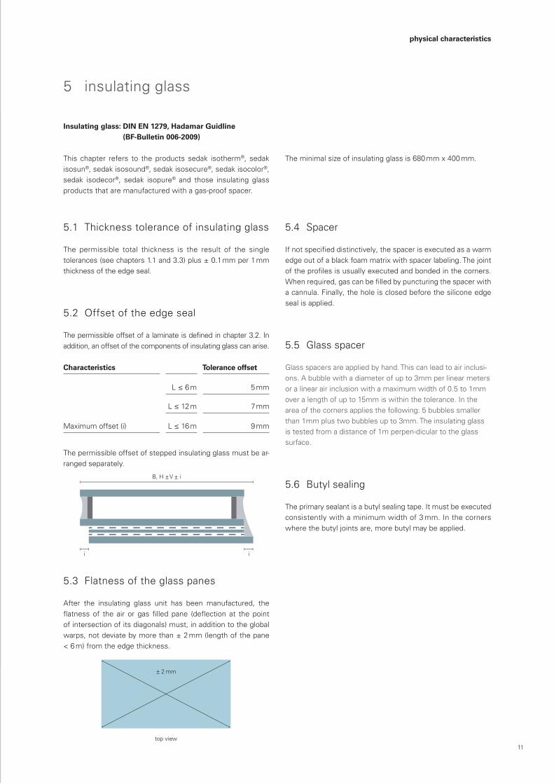
5.2 Offset of the edge seal
Thepermissibleoffsetofalaminateisdefinedinchapter3.2.Inaddition, an offset of the components of insulating glass can arise.
Characteristics Tolerance offset
Maximum offset (i)
L≤6m 5 mm
L≤12m 7 mm
L≤16m 9 mm
The permissible offset of stepped insulating glass must be ar-ranged separately.
5.3 Flatness of the glass panes
After the insulating glass unit has been manufactured, theflatnessof the air or gas filled pane (deflection at thepointof intersection of its diagonals) must, in addition to the global warps, not deviate by more than ± 2 mm (length of the pane <6m)fromtheedgethickness.
5.4 Spacer
Ifnotspecifieddistinctively,thespacerisexecutedasawarmedge out of a black foam matrix with spacer labeling. The joint oftheprofilesisusuallyexecutedandbondedinthecorners.Whenrequired,gascanbefilledbypuncturingthespacerwitha cannula. Finally, the hole is closed before the silicone edge seal is applied.
5.5 Glass spacer
Glass spacers are applied by hand. This can lead to air inclusi-ons.Abubblewithadiameterofupto3mmperlinearmetersor a linear air inclusion with a maximum width of 0.5 to 1mm overalengthofupto15mmiswithinthetolerance.Intheareaofthecornersappliesthefollowing:5bubblessmallerthan 1mm plus two bubbles up to 3mm. The insulating glass is tested from a distance of 1m perpen-dicular to the glass surface.
5.6 Butylsealing
Theprimarysealantisabutylsealingtape.Itmustbeexecuted consistentlywithaminimumwidthof3mm.Inthecornerswhere the butyl joints are, more butyl may be applied.
Theminimalsizeofinsulatingglassis680mmx400mm.
12
5.7 Edge seal
The width of the secondary sealant (silicone edge sealant) is usually8mm.Ifadistinctivewidthofthesiliconeedgesealantisrequired,theclientisobligedtospecifythat.The client is also responsible for the dimensioning of the in-sulating glass pane (static load, climatic load, etc.). Provided that no other agreement has been arranged, the edge seal is executedwithblack2Ksilicone(DC993orequivalent).Theclient is obliged to verify the compatibility with adjacent materials that are not part of the order with sedak GmbH & Co. KG.Variations and deviations regarding the spacer or the edge seal must be arranged before an order is placed.
physical characteristics
5.8 Glass coatings
Coatings (e.g. low-e or solar control coatings) are executed accordingtotheregulationsofDINEN1096.Thepermissible sizesandtypesofdefectsarealsodefinedaccordingtothatstandard. The permissible defects of the coating are to be seen additionally to the permissible defects of the single glass pane or the laminate.
13
top view
Glasdicke
1000 mm
B
V V
B bzw H
top view
a
b
c 3500 mm
300 mm
3500 mm
300 mm
S
45
S
D+-tdi
45 45
90
2b
6b P
2b
d
B
PK
PG
PB
PV
PC
PC
t1t2
t3
t4B – t
B + t
top view
H –
t
H +
t
2a
ax
B bzw H 300 mm
B, H V i
i i
PSS +
DMin
Randzone (R)
Falzzone (F)
Hauptzone Breite
Lichte Breite (b)
Scheibenbreite
b/10 b/10
F F
Hauptzone Breite
Randzone (min. 15 mm umlaufend)
1000 mm
td
Id
2 mm
visual characteristics
6.1 Sphereofvalidity
Thischapterreferstofortheassessmentofthevisualqualityoftheexposedsurfaceofaglasspaneaftertheinstallment.Itis valid for clear glass, coated glass, and glass colored through- out the mass, for both single glass panes (including heat-strengthened glass and fully tempered glass) and laminates. Restrictions are valid for glass with inserts, patterned or cast glass,andattack-resistantandfireprotectiveglazings.Whenusingthoseproducts,thematerialsrequiredmustbeconsidered.
Thequality isassessedaccording to the futureuseand theinstallationsituation.Iftheclientdoesnotspecifyanyfutureuse, the glass is considered to be used as a vertical façade glass without any special approval requirements andwithcovered edges. The view and assessment direction is always the direction of the exterior view.
6.2 Inspection
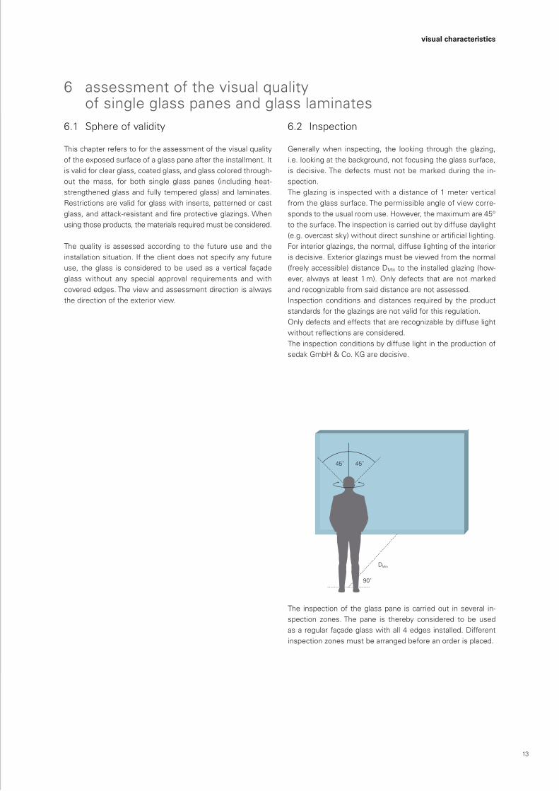
Generallywhen inspecting, the looking through the glazing,i.e. looking at the background, not focusing the glass surface, is decisive. The defects must not be marked during the in-spection.Theglazingisinspectedwithadistanceof1meterverticalfrom the glass surface. The permissible angle of view corre-sponds to the usual room use. However, the maximum are 45° to the surface. The inspection is carried out by diffuse daylight (e.g.overcastsky)withoutdirectsunshineorartificiallighting.Forinteriorglazings,thenormal,diffuselightingoftheinteriorisdecisive.Exteriorglazingsmustbeviewedfromthenormal(freely accessible) distance DMintotheinstalledglazing(how-ever, always at least 1 m). Only defects that are not marked andrecognizablefromsaiddistancearenotassessed.Inspectionconditionsanddistances requiredby theproductstandardsfortheglazingsarenotvalidforthisregulation.Onlydefectsandeffectsthatarerecognizablebydiffuselightwithoutreflectionsareconsidered.The inspection conditions by diffuse light in the production of sedak GmbH & Co. KG are decisive.
The inspection of the glass pane is carried out in several in-spection zones.The pane is thereby considered to be usedas a regular façade glass with all 4 edges installed. Different inspectionzonesmustbearrangedbeforeanorderisplaced.
6 assessmentofthevisualquality of single glass panes and glass laminates
14
top view
Glasdicke
1000 mm
B
V V
B bzw H
top view
a
b
c 3500 mm
300 mm
3500 mm
300 mm
S
45
S
D+-tdi
45 45
90
2b
6b P
2b
d
B
PK
PG
PB
PV
PC
PC
t1t2
t3
t4B – t
B + t
top view
H –
t
H +
t
2a
ax
B bzw H 300 mm
B, H V i
i i
PSS +
DMin
Randzone (R)
Falzzone (F)
Hauptzone Breite
Lichte Breite (b)
Scheibenbreite
b/10 b/10
F F
Hauptzone Breite
Randzone (min. 15 mm umlaufend)
1000 mm
td
Id
2 mm
visual characteristics
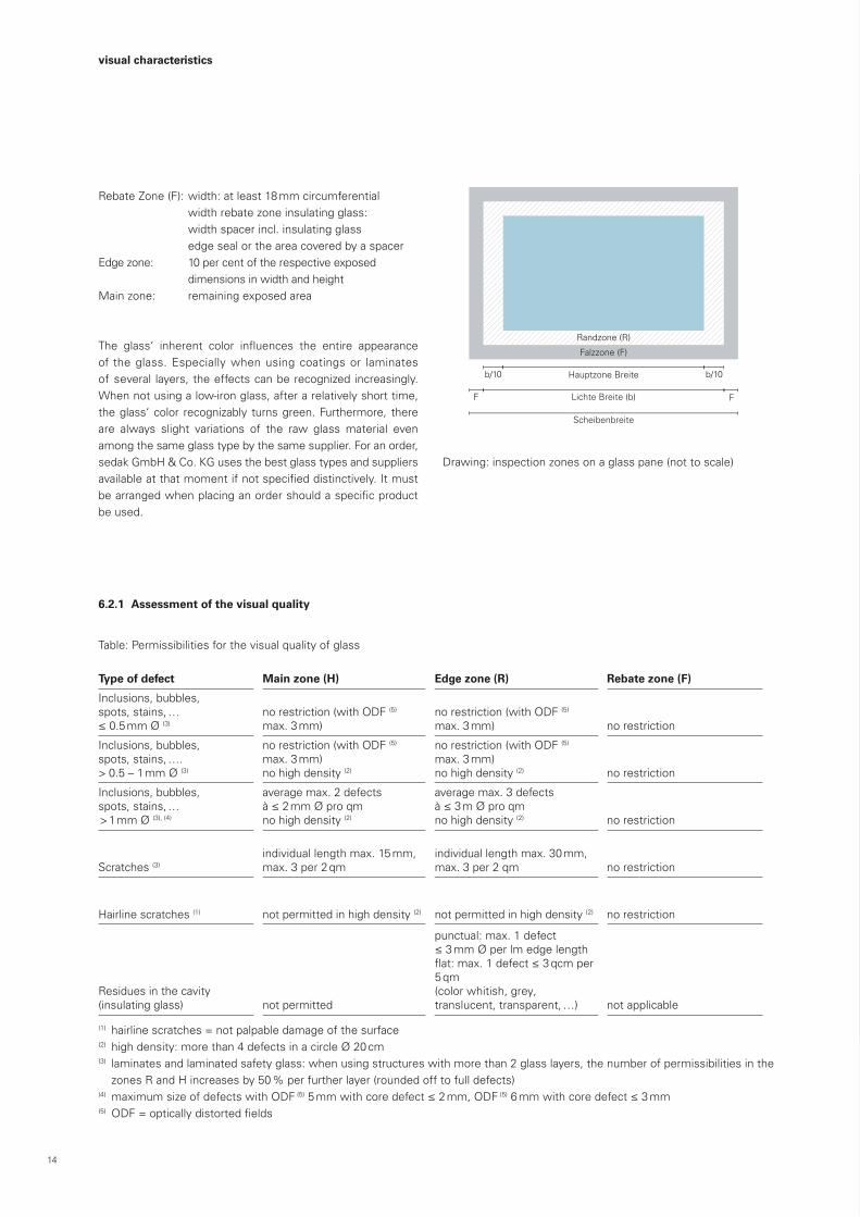
RebateZone(F):width:atleast18mmcircumferential widthrebatezoneinsulatingglass:
width spacer incl. insulating glass edge seal or the area covered by a spacerEdgezone: 10 per cent of the respective exposed
dimensions in width and heightMainzone: remainingexposedarea
The glass‘ inherent color influences the entire appearanceof the glass. Especially when using coatings or laminates ofseveral layers,theeffectscanberecognizedincreasingly.When not using a low-iron glass, after a relatively short time, theglass‘color recognizably turnsgreen.Furthermore, thereare always slight variations of the raw glass material even among the same glass type by the same supplier. For an order, sedak GmbH & Co. KG uses the best glass types and suppliers availableatthatmomentifnotspecifieddistinctively.Itmustbearrangedwhenplacinganordershouldaspecificproductbe used.
6.2.1 Assessment of the visual quality
Table:Permissibilitiesforthevisualqualityofglass
Drawing:inspectionzonesonaglasspane(nottoscale)
Type of defect Main zone (H) Edge zone (R) Rebate zone (F)
Inclusions,bubbles, spots, stains, … ≤0.5mmØ(3)
no restriction (with ODF (5) max. 3 mm)
no restriction (with ODF (5) max. 3 mm) no restriction
Inclusions,bubbles, spots, stains, …. >0.5–1mmØ(3)
no restriction (with ODF (5) max. 3 mm)no high density (2)
no restriction (with ODF (5) max. 3 mm)no high density (2) no restriction
Inclusions,bubbles, spots, stains, … >1mmØ(3), (4)
average max. 2 defects à≤2mmØproqmno high density (2)
average max. 3 defects à≤3mØproqmno high density (2) no restriction
Scratches (3)individual length max. 15 mm, max.3per2qm
individual length max. 30 mm, max.3per2qm no restriction
Hairline scratches (1) not permitted in high density (2) not permitted in high density (2) no restriction
Residues in the cavity (insulating glass) not permitted
punctual:max.1defect ≤3mmØperlmedgelengthflat:max.1defect≤3qcmper5qm(color whitish, grey, translucent, transparent, …) not applicable
(1) hairline scratches = not palpable damage of the surface(2) highdensity:morethan4defectsinacircleØ20cm(3) laminatesandlaminatedsafetyglass:whenusingstructureswithmorethan2glasslayers,thenumberofpermissibilitiesinthezonesRandHincreasesby50%perfurtherlayer(roundedofftofulldefects)
(4) maximumsizeofdefectswithODF (5)5mmwithcoredefect≤2mm,ODF (5)6mmwithcoredefect≤3mm(5) ODF=opticallydistortedfields
15
visual characteristics
6.2.2 Assessment of tempered glass
The surface of tempered glass is further influenced.The as-sessmentaccordingtothelistinchapter6.2.1remainsvalid.Additionally,thecriteriamentionedbelowareconsidered.Thisis valid for all types of thermally treated glass, especially for heat-strengthened glass (TVG) as well as fully tempered glass (ESG) and heat-soaked fully tempered glass (ESG-H).
Tempered glass is subject to several physical characteristics that do not represent any reason for complaints. The most im-portantcharacteristicsarelistedbelow:
Rollerwaves(localwarps):Duetothetransportoftheglassonthe rolls of the furnace, the glass surface may become wavy (roller waves). Besides the warps, this can also lead to marginal visual damages.
Anisotropies:Theyarecausedbytheinternalstressdistributionthat occurs during the tempering process. Under polarizedlight, the birefringence (tiger pattern) becomes visual. The amountofpolarizedlightvariesdependingonthetimeofdayand the season. The effect increases with a higher glass thick-ness. However, the effect cannot be avoided basically.
Wettabilityofthesurface:Duetomarkscausedbyrolls,labels,suction cups, etc., the wettability of the surface can vary. This only becomes visual when the surface is exposed to humidity. The appearance of the dry glass pane is decisive.
During the production of tempered glass, marks, so called “heat marks” or “orange peel”, on the glass surface might be caused. These defects are assessed according to the table in chapter6.2.1.
6.2.3 Assessment of glass edges
sedakGmbH&Co.KGoffersseveralhighqualityedges.Whenexposedorvisualedgesarerequired,aconsultancyregardingtheaccurateedgequalityshouldtakeplacebeforeanorderisplaced.Iftheclientdoesnotdefineanyedgequality,theedgesarepolished.Temperedglassrequiresatleastagroundedge(KGN)toavoidanydamagesoftheedgeduringthetemperingprocess.
Depending on the edge quality and the production process,tool traces might be more or less visual on the edge. These traces may be periodically repetitive. They do not represent any reason forcomplaints.Fora reliableclarification,asample isrecommended.
Edgesmustbefreeofopenflakesorbreaks.Fromtheedgetype KG on, the edges may not be sharp.
16
top view
Glasdicke
1000 mm
B
V V
B bzw H
top view
a
b
c 3500 mm
300 mm
3500 mm
300 mm
S
45
S
D+-tdi
45 45
90
2b
6b P
2b
d
B
PK
PG
PB
PV
PC
PC
t1t2
t3
t4B – t
B + t
top view
H –
t
H +
t
2a
ax
B bzw H 300 mm
B, H V i
i i
PSS +
DMin
Randzone (R)
Falzzone (F)
Hauptzone Breite
Lichte Breite (b)
Scheibenbreite
b/10 b/10
F F
Hauptzone Breite
Randzone (min. 15 mm umlaufend)
1000 mm
td
Id
2 mm
top view
Glasdicke
1000 mm
B
V V
B bzw H
top view
a
b
c 3500 mm
300 mm
3500 mm
300 mm
S
45
S
D+-tdi
45 45
90
2b
6b P
2b
d
B
PK
PG
PB
PV
PC
PC
t1t2
t3
t4B – t
B + t
top view
H –
t
H +
t
2a
ax
B bzw H 300 mm
B, H V i
i i
PSS +
DMin
Randzone (R)
Falzzone (F)
Hauptzone Breite
Lichte Breite (b)
Scheibenbreite
b/10 b/10
F F
Hauptzone Breite
Randzone (min. 15 mm umlaufend)
1000 mm
td
Id
2 mm
visual characteristics
7 assessment of the visual qualityofprintedglass7.1 Sphere of validity
Thischapterreferstotheassessmentofthevisualqualityoffull-surface and partial-surface enameled and screen-printed (e.g. sedak secudecor®, sedak secucolor®, sedak isodecor®, sedak isocolor®) glass units which are manufactured as fully tempered or heat-strengthened glass by the applying and the subsequentburninginofceramicinks.Itisalsovalidforfull-surface and partial-surface varnished plane glass units (with shiningormattsurface).Thevisualqualityofthecolorcoatedsurface is assessed according to the tables of this chapter when a viewing from one side of the non-coated or non-varnished surface is carried out.
This regulation cannot be consulted for the visual assessment of glass defects of the respectively used glass type.
For the used glass types and products, separate product-spe-cific,visualassessmentregulationsarevalid.Theassessmentis carried out according to the following described inspection principles by means of the permissibilities stated in the tables.The exposed glass surface remaining after the installment is assessed by viewing the non-coated or non-varnished glass surface (through the glass). This regulation is not valid for custom- madeglasslikeattack-resistantglazings,fireprotectiveglazings and sandblasted surfaces.
Thequality isassessedaccording to the futureuseand theinstallationsituation.Iftheclientdoesnotspecifyanyfutureuse, the glass is considered to be used as a vertical façade glasswithoutanyspecialapprovalrequirementswithinstallededges. The view and assessment direction is always the direc-tion of the non-printed glass side.
7.2 Installationareas
Enameled glass can be manufactured both as monolithic panes and laminates. However, it must be borne in mind that the staticvaluesofaprintedglassmustberecognizedlowerthanthose of non-printed glass.Ifprintedglass isused in laminates, it isrecommendabletoclarify the future use in order to determine whether the print shouldbewithinthelaminateorontheexteriorside.Itmustbe taken into account that environmental conditions (particularly the exposure to SO2, NO2, flue dust and further aggressivesubstances) can affect an exterior print and its visual appear-ance noticeably.
7.3 Inspectionofprintedglass
Theinspectioniscarriedoutwiththeviewoftheglazing’snon-coated or non-varnished surface. Defects must not be marked. The measuring of the homogeneity of color is carried out on the printed side of the glass.The visual quality of colorcoated glass is assessed from adistance of at least 3 m and vertically to the surface (deviation max. 30°).The viewing level for bent glass is the tangent to the viewing point. The assessment is carried out by diffuse daylight (e.g. overcast sky), without direct sunshine or artificial lighting, without a lit background or a covering of the printed layer.Defects that are not recognizable from this distance are notassessed.Theglazing in rooms (interiorglazings) is tobe inspectedbynormal (diffuse) lighting being planned for the room use.Further visual criteria like e.g. degree of shine, degree of re-flection,temperingdefects,anisotropies,...aretobeassessedinadditionaccording tochapter6.Theeffectscanbeaddedtogether.
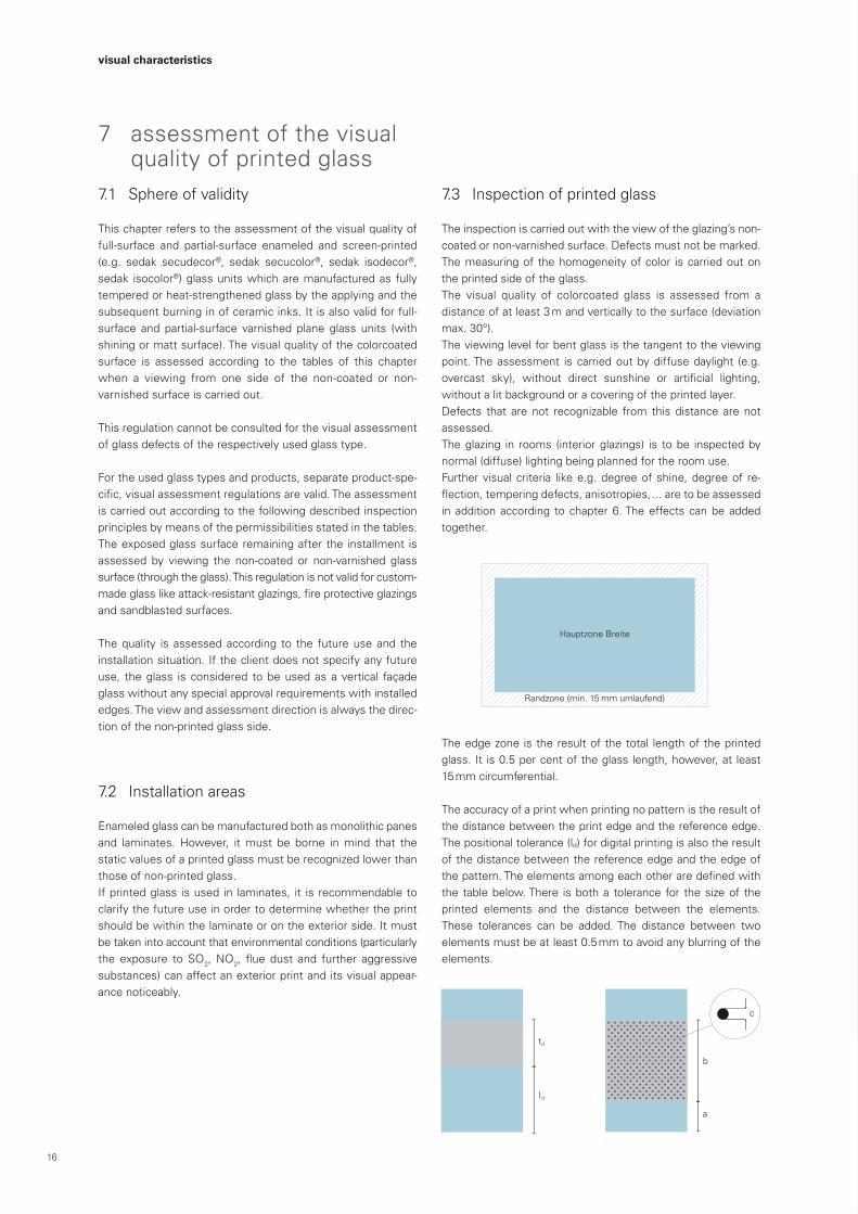
Theedgezone istheresultofthetotal lengthoftheprintedglass.It is0.5percentoftheglasslength,however,at least 15 mm circumferential.
The accuracy of a print when printing no pattern is the result of the distance between the print edge and the reference edge. The positional tolerance (ld) for digital printing is also the result of the distance between the reference edge and the edge of thepattern.Theelementsamongeachotheraredefinedwiththe tablebelow.There isbotha tolerance for thesizeof theprinted elements and the distance between the elements. These tolerances can be added. The distance between two elements must be at least 0.5 mm to avoid any blurring of the elements.
17
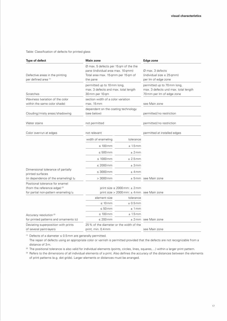
Table:Classificationofdefectsforprintedglass
Type of defect Main zone Edge zone
Defective areas in the printing perdefinedarea(1)
Ømax.5defectsper15qmofthethepane(individualareamax.10qmm)Totalareamax.15qmmper15qmofthe pane
Ømax.3defects (individualsize≤25qmm) perlmofedgezone
Scratches
permitted up to 10 mm long, max. 3 defects and max. total length 30mmper10qm
permitted up to 70 mm long, max. 3 defects und max. total length 70mmperlmofedgezone
Waviness (variation of the color within the same color shade)
section width of a color variation max. 15 mm seeMainzone
Clouding / misty areas / shadowingdependent on the coating technology (see below) permitted / no restriction
Water stains not permitted permitted / no restriction
Color over-run at edges not relevant permitted at installed edges
Dimensional tolerance of partially printed surfaces(in dependence of the enameling) td
width of enameling tolerance
seeMainzone
≤100mm ± 1.5 mm
≤500mm ± 2 mm
≤1000mm ± 2.5 mm
≤2000mm ± 3 mm
≤3000mm ± 4 mm
> 3000 mm ± 5 mm
Positional tolerance for enamel (from the reference edge) (2) for partial non-pattern enameling ld
printsize≤2000mm:±2mmprintsize>2000mm:±4mm seeMainzone
Accuracyresolution (3) for printed patterns and ornaments (c)
elementsize tolerance
seeMainzone
≤10mm ± 0.5 mm
≤50mm ± 1 mm
≤100mm ± 1.5 mm
≤200mm ± 2 mm
Deviating superposition with prints of several paint-layers
25 % of the diameter or the width of the print, min. 0.4 mm seeMainzone
(1) Defectsofadiameter≤0.5mmaregenerallypermitted. Therepairofdefectsusinganappropriatecolororvarnishispermittedprovidedthatthedefectsarenotrecognizablefroma
distance of 3 m.(2) Thepositionaltoleranceisalsovalidforindividualelements(points,circles,lines,squares,...)withinalargerprintpattern.(3) Referstothedimensionsofallindividualelementsofaprint.Alsodefinestheaccuracyofthedistancesbetweentheelements
of print patterns (e.g. dot grids). Larger elements or distances must be arranged.
visual characteristics
18
visual characteristics
– When printing patterns with narrow grids (partial areas or distances of partial areas < 5 mm) a so called “Moiré Pattern” may occur. This is no deviation and due to the ornament’snature.
– The human eye reacts very critically when it is confronted withfigures,shapesanddistances<3mm,orcolor tran- sitions. Even the slightest tolerances are already perceived as a gross deviation. If this effect is to be avoided, the details must be settled before the beginning of the fabri-cation.
– Furthermore, the subjective perception of a color differs de-pending on the color shade. Color differences of blue tones e.g. are observed more clearly than green tones. This factor must be considered when assessing such color differences.
Color deviations can also occur within the same production unit due to diverse factors. That might be caused by varia-tions of the basic glass‘ inherent color, of inorganic basic substances of the color, of the exact burning temperature during the burning process, of the color mixing (particularly withorder-specificmixedcolors),andmechanicinfluencesduringtheapplicationoftheenamelcolor.Thepane’ssizeandthicknessalsohaveaninfluencetothefinalproduct.Ifcolordeviationsoccur, theyareverifiedbycomparing themanufacturedpanetoadeterminedreferencesample.Asan indicator for a comparative measurement for standard colors,areflectionmeasurementatfivemeasuringpointswith Ø ΔE<4 can be considered permissible (exception:blue tones and acid-etch tones).
Thiscorrespondstotheclassificationofacolordifferencethat is visible to the naked eye by the same light conditions (decisive are the conditions of the production hall).
Itmustalsobeborneinmindthatdifferencesbetweenasmallsampleandalargefinishedpanemayoccurandthatnot all surfaces and colors are suitable for a measurement of theΔE value.This is especially the casewithmetalliccolors and coatings.
– For digital prints and printed patterns, a color difference can only be assessed with the naked eye for technical reasons. Such a technical measurement is carried out with a Konica Minolta colorimeter.
– When using acid-etch tones (regardless of whether it is a color print or the surface is treated with caustic agents), color variations may occur, particularly under backlight con-ditions. Such color variations may appear as a formation of stains. These are caused by variations of the glass mass and in the surface, and cannot always be excluded.
– The light transmission and therefore the opaqueness de-cisively depend on the used printing technology and the chosen color. Light colors and thin paint-layers (e.g. digital print of one layer) naturally have higher light transmission values and provide therefore a lower opaqueness. If thatvalue is important for the future use, it is essential to settle thedetailsbeforeanorderisplaced.Thehighertheopaque-ness the more changes the appearance of the print on the non-printedglassside.A100percentopaquenesscanonlybeofferedafterthetechnicaldetailshavebeenclarifiedanda sample has been produced.
– The light conditions during the viewing of the glass vary depending on the daytime and the season. Every layer of the surface absorbs and reflects a part of the light.Thelight that meets the color or its pigments is absorbed or re- flectedbythiscolor.Therefore,thecolorappearsdifferentlydepending on the light source.
– Only a print on glass can be compared with a print on glass. Comparing it to a print on paper is not possible.
7.3.1 Assessment of color transitions and color deviations
19
7.4 Production technology of printing glass
7.4.1 Roller application technology
When using the roller application technology, the glass pane is printed by a rubber-covered printing roller. The roller has grooves that allow an even application. After the printing, these grooves are still visible on the color side of the print. The layer is thicker with the roller application technology than with the digital printing technology. The layer thickness can only bechangedundercertaincircumstances.Acolorover-run ispossibleespeciallywithnon-rectangularshapedpanes.Atthepane’sedgesperpendiculartothedirectioninwhichtheroller is applying, color over-runs can occur. The roller application technology is particularly suitable when the glass surface is largely and monochromatically printed.
7.4.2 Digital printing technology
When using the digital printing technology, a mobile print head moves over the pane. During the printing process, the print head can mix colors or apply previously mixed colors. Shapes and pictures almost of all kinds are possible. The paint-layer is usually not as thick as when using the roller application tech-nology.Attheedgesofaprint,afinespraymistmayoccur.The available colors base on a special color system. Therefore, the details about whether the required color can be shownwithin the system must be arranged. The digital printing tech-nology is especially suitable for glass panes that are to be printed with patterns, pictures, or different colors. For the print- ing, the client must make an appropriate printing template.
7.4.3 Thermal treatment
Enameled and printed glass can only be produced as fully tem-pered glass (ESG), heat-soaked fully tempered glass (ESG-H) or heat-strengthened glass (TVG). Only the side of the glass that is averted from the rolls of the tempering furnace can be printed. During the tempering process, the glass may change duetotheproduction(seechapter3).Itmustbeconsideredthat the static values (e.g. bending tensile strength, mechanic values, etc) of printed enameled glass and non-printed glass cannot be compared.
7.4.4 Laminated glass
When using printed glass to the lamination side, the use and the appearance must be arranged. Particularly with acid-etch tones, the color shape may be “swallowed” as a result of reducing the optical density of the printing.
For further information and details please contact our sales department.
visual characteristics

sedak GmbH & Co. KGEinsteinring 186368GersthofenGermany
Phone +49 821 2494-222Fax +49 821 2494-777