Embed Size (px)
DESCRIPTION
A step towards the quantum computer!
Citation preview
Observation of quantum jumps in a superconducting artificial atom
R. Vijay∗, D. H. Slichter∗, and I. SiddiqiQuantum Nanoelectronics Laboratory, Department of Physics, University of California, Berkeley CA 94720
(Dated: September 16, 2010)
A continuously monitored quantum system pre-pared in an excited state will decay to its groundstate with an abrupt jump. The jump occursstochastically on a characteristic time scale T1,the lifetime of the excited state. These quan-tum jumps, originally envisioned by Bohr, havebeen observed in trapped atoms and ions1–3, sin-gle molecules4, photons5, and single electrons incyclotrons6. Here we report the first observa-tion of quantum jumps in a macroscopic quantumsystem, in our case a superconducting “artificialatom” or quantum bit (qubit)7 coupled to a su-perconducting microwave cavity8. We use a fast,ultralow-noise parametric amplifier9 to amplifythe microwave photons used to probe the qubitstate, enabling continuous high-fidelity monitor-ing of the qubit. This technique represents a ma-jor step forward for solid state quantum infor-mation processing, potentially enabling quantumerror correction and feedback10, which are essen-tial for building a quantum computer. Our tech-nology can also be readily integrated into hybridcircuits involving molecular magnets, nitrogen va-cancies in diamond, or semiconductor quantumdots.
Quantum error correction, an essential component ofa practical quantum computer, requires real-time, high-fidelity readout to accurately determine the quantumstate of the system and to allow rapid feedback10. Thereadout must also be quantum non-demolition (QND),that is, it must leave the system in an eigenstate of themeasured observable11, thus allowing repeated measure-ments. To fulfill these requirements, we use the circuitquantum electrodynamics (cQED) architecture, wherethe superconducting qubit is dispersively coupled to asuperconducting cavity12, in analogy to an atom in aFabry-Perot cavity. The cavity decouples the qubit fromits environment, improving coherence times8,13 while alsoenabling a continuous, high visibility, QND measurementof the qubit state by probing the resonant frequency ofthe cavity14. These properties make the cQED architec-ture an ideal system for observing quantum jumps15.
Despite successfully demonstrating QND measure-ment with several kinds of superconducting qubits8,13,16,cQED implementations with linear cavities have typicallysuffered from low single-shot fidelity, precluding the ob-servation of quantum jumps. This is primarily due to in-efficient amplification of the photons leaving the cavity.State of the art cryogenic semiconductor microwave am-plifiers add about 30 photons of noise, necessitating manyaverages to see the few-photon readout signal14. Using
more readout photons induces qubit state mixing17, thuslimiting the fidelity. Other high fidelity readout schemesimplemented for superconducting qubits are either tooslow18 or scramble the qubit state19. Josephson para-metric amplifiers20,21 with near quantum limited noiseperformance can potentially enable single shot readoutin the cQED architecture, but most existing designs havean instantaneous bandwidth below 1 MHz, too small toenable real time monitoring of the qubit state. Since su-perconducting qubit lifetimes are typically around 1 µs,one would need a bandwidth of order 10 MHz to resolvequantum jumps between qubit states with high fidelity.We achieve this by using a low quality factor (Q) nonlin-ear resonator as a parametric amplifier9.
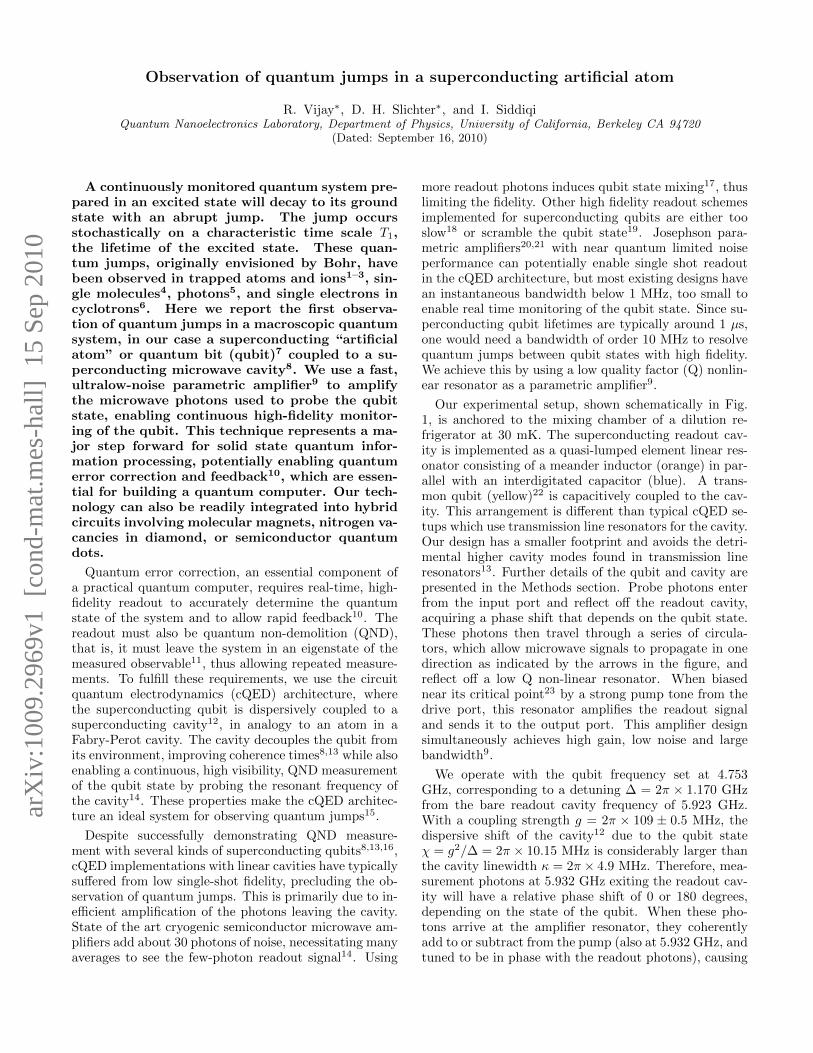
Our experimental setup, shown schematically in Fig.1, is anchored to the mixing chamber of a dilution re-frigerator at 30 mK. The superconducting readout cav-ity is implemented as a quasi-lumped element linear res-onator consisting of a meander inductor (orange) in par-allel with an interdigitated capacitor (blue). A trans-mon qubit (yellow)22 is capacitively coupled to the cav-ity. This arrangement is different than typical cQED se-tups which use transmission line resonators for the cavity.Our design has a smaller footprint and avoids the detri-mental higher cavity modes found in transmission lineresonators13. Further details of the qubit and cavity arepresented in the Methods section. Probe photons enterfrom the input port and reflect off the readout cavity,acquiring a phase shift that depends on the qubit state.These photons then travel through a series of circula-tors, which allow microwave signals to propagate in onedirection as indicated by the arrows in the figure, andreflect off a low Q non-linear resonator. When biasednear its critical point23 by a strong pump tone from thedrive port, this resonator amplifies the readout signaland sends it to the output port. This amplifier designsimultaneously achieves high gain, low noise and largebandwidth9.
We operate with the qubit frequency set at 4.753GHz, corresponding to a detuning ∆ = 2π × 1.170 GHzfrom the bare readout cavity frequency of 5.923 GHz.With a coupling strength g = 2π × 109 ± 0.5 MHz, thedispersive shift of the cavity12 due to the qubit stateχ = g2/∆ = 2π × 10.15 MHz is considerably larger thanthe cavity linewidth κ = 2π × 4.9 MHz. Therefore, mea-surement photons at 5.932 GHz exiting the readout cav-ity will have a relative phase shift of 0 or 180 degrees,depending on the state of the qubit. When these pho-tons arrive at the amplifier resonator, they coherentlyadd to or subtract from the pump (also at 5.932 GHz, andtuned to be in phase with the readout photons), causing
arX
iv:1
009.
2969
v1 [
cond
-mat
.mes
-hal
l] 1
5 Se
p 20
10
2
b
InputDrive
Output
c
Readout cavity + qubit
Amplifier resonatora
FIG. 1: Experimental setup. In (a), readout photons (black arrow) enter from the input port and are directed through amicrowave circulator to a 180◦ hybrid, which converts the single-ended microwave signal into a differential one. The photonsinteract with the readout cavity and the reflected signal (purple arrows) carries information about the qubit state toward thenon-linear resonator through three circulators, which isolate the readout and qubit from the strong pump of the amplifierresonator. A directional coupler combines this signal with pump photons (green arrow) from the drive port. The pumpednonlinear resonator amplifies the readout signal, and the amplified signal (red arrows) is reflected and sent through the thirdcirculator to the output port. The signal is further amplified by cryogenic and room temperature amplifiers before beingmixed down to zero frequency, digitized, and stored in a computer. Qubit manipulation pulses enter on the same line as thereadout pulses. (b) false-color optical image of the readout resonator, formed by a meander inductor (orange) shunted by aninterdigitated capacitor (blue). The transmon qubit (yellow) is capacitively coupled to the resonator. The detail view showsthe qubit loop. Scale bars are 100 µm (main view) and 10 µm (detail view). (c) false-color optical image of the amplifierresonator showing the superconducting loop (pink) and junctions (black), shunted by large parallel-plate capacitors (cyan) ona SiNx-coated Nb ground plane (brown). Scale bars are 100 µm (main view) and 5 µm (detail view).
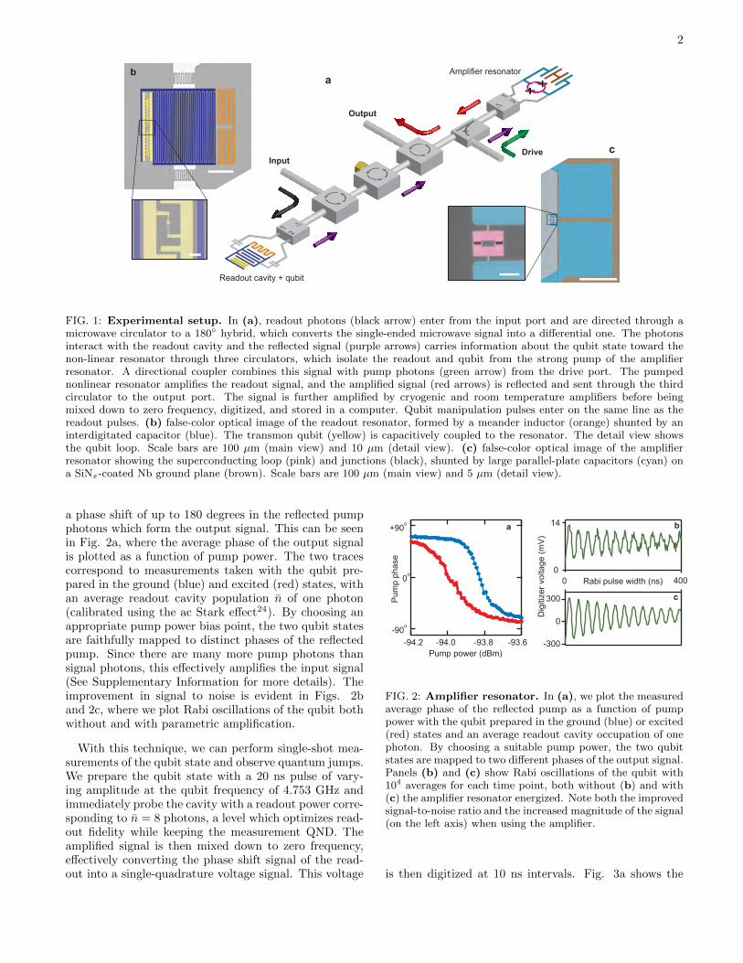
a phase shift of up to 180 degrees in the reflected pumpphotons which form the output signal. This can be seenin Fig. 2a, where the average phase of the output signalis plotted as a function of pump power. The two tracescorrespond to measurements taken with the qubit pre-pared in the ground (blue) and excited (red) states, withan average readout cavity population n̄ of one photon(calibrated using the ac Stark effect24). By choosing anappropriate pump power bias point, the two qubit statesare faithfully mapped to distinct phases of the reflectedpump. Since there are many more pump photons thansignal photons, this effectively amplifies the input signal(See Supplementary Information for more details). Theimprovement in signal to noise is evident in Figs. 2band 2c, where we plot Rabi oscillations of the qubit bothwithout and with parametric amplification.
With this technique, we can perform single-shot mea-surements of the qubit state and observe quantum jumps.We prepare the qubit state with a 20 ns pulse of vary-ing amplitude at the qubit frequency of 4.753 GHz andimmediately probe the cavity with a readout power corre-sponding to n̄ = 8 photons, a level which optimizes read-out fidelity while keeping the measurement QND. Theamplified signal is then mixed down to zero frequency,effectively converting the phase shift signal of the read-out into a single-quadrature voltage signal. This voltage
e s a h p p m
u
P
Pump power (dBm)
a
-94.2 -94.0 -93.8 -93.6 -90 o
+90 o
0 o
) V
m
( e g a t l o v r e z i t i g i
D
Rabi pulse width (ns)
b
c
400 0
14
300
-300
0
0
FIG. 2: Amplifier resonator. In (a), we plot the measuredaverage phase of the reflected pump as a function of pumppower with the qubit prepared in the ground (blue) or excited(red) states and an average readout cavity occupation of onephoton. By choosing a suitable pump power, the two qubitstates are mapped to two different phases of the output signal.Panels (b) and (c) show Rabi oscillations of the qubit with104 averages for each time point, both without (b) and with(c) the amplifier resonator energized. Note both the improvedsignal-to-noise ratio and the increased magnitude of the signal(on the left axis) when using the amplifier.
is then digitized at 10 ns intervals. Fig. 3a shows the
3
a b c
-150 -100 -50 0 50 100Time (ns)
qubi
tex
cita
tion
read
out
10008006004002000Time (ns)
-0.5 0 0.5 1.0Digitizer voltage (V)
Dig
itize
r vol
tage
(V)
8006004002000Time (ns)
0.8
0.4
0.0
-0.4
1086420-2Time
Digitizer voltage (V)-0.5 0 0.5
(μs)
-0.6
-0.4
-0.2
0.0
0.2
0.4
Dig
itize
r vol
tage
(V)
1086420-2Time (μs)
-3 0 3 6 9 12Time (μs)
qubi
tex
cita
tion
read
out
d e f
0
π
2π
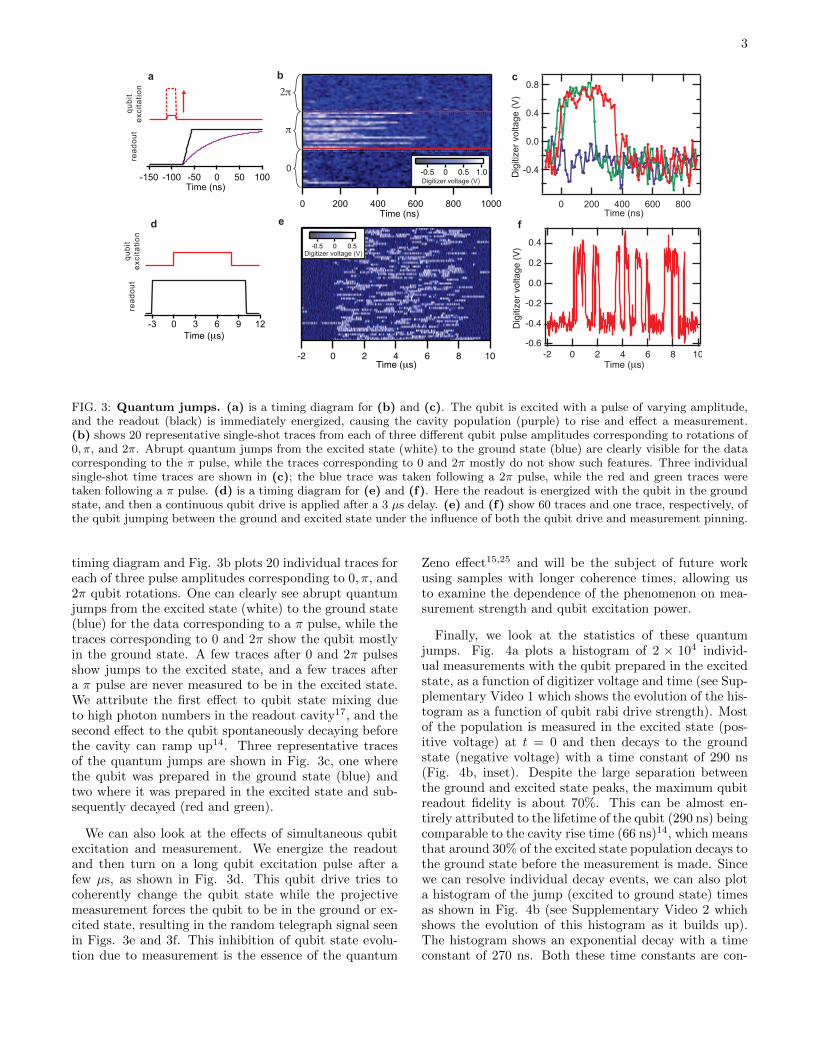
FIG. 3: Quantum jumps. (a) is a timing diagram for (b) and (c). The qubit is excited with a pulse of varying amplitude,and the readout (black) is immediately energized, causing the cavity population (purple) to rise and effect a measurement.(b) shows 20 representative single-shot traces from each of three different qubit pulse amplitudes corresponding to rotations of0, π, and 2π. Abrupt quantum jumps from the excited state (white) to the ground state (blue) are clearly visible for the datacorresponding to the π pulse, while the traces corresponding to 0 and 2π mostly do not show such features. Three individualsingle-shot time traces are shown in (c); the blue trace was taken following a 2π pulse, while the red and green traces weretaken following a π pulse. (d) is a timing diagram for (e) and (f). Here the readout is energized with the qubit in the groundstate, and then a continuous qubit drive is applied after a 3 µs delay. (e) and (f) show 60 traces and one trace, respectively, ofthe qubit jumping between the ground and excited state under the influence of both the qubit drive and measurement pinning.
timing diagram and Fig. 3b plots 20 individual traces foreach of three pulse amplitudes corresponding to 0, π, and2π qubit rotations. One can clearly see abrupt quantumjumps from the excited state (white) to the ground state(blue) for the data corresponding to a π pulse, while thetraces corresponding to 0 and 2π show the qubit mostlyin the ground state. A few traces after 0 and 2π pulsesshow jumps to the excited state, and a few traces aftera π pulse are never measured to be in the excited state.We attribute the first effect to qubit state mixing dueto high photon numbers in the readout cavity17, and thesecond effect to the qubit spontaneously decaying beforethe cavity can ramp up14. Three representative tracesof the quantum jumps are shown in Fig. 3c, one wherethe qubit was prepared in the ground state (blue) andtwo where it was prepared in the excited state and sub-sequently decayed (red and green).
We can also look at the effects of simultaneous qubitexcitation and measurement. We energize the readoutand then turn on a long qubit excitation pulse after afew µs, as shown in Fig. 3d. This qubit drive tries tocoherently change the qubit state while the projectivemeasurement forces the qubit to be in the ground or ex-cited state, resulting in the random telegraph signal seenin Figs. 3e and 3f. This inhibition of qubit state evolu-tion due to measurement is the essence of the quantum
Zeno effect15,25 and will be the subject of future workusing samples with longer coherence times, allowing usto examine the dependence of the phenomenon on mea-surement strength and qubit excitation power.
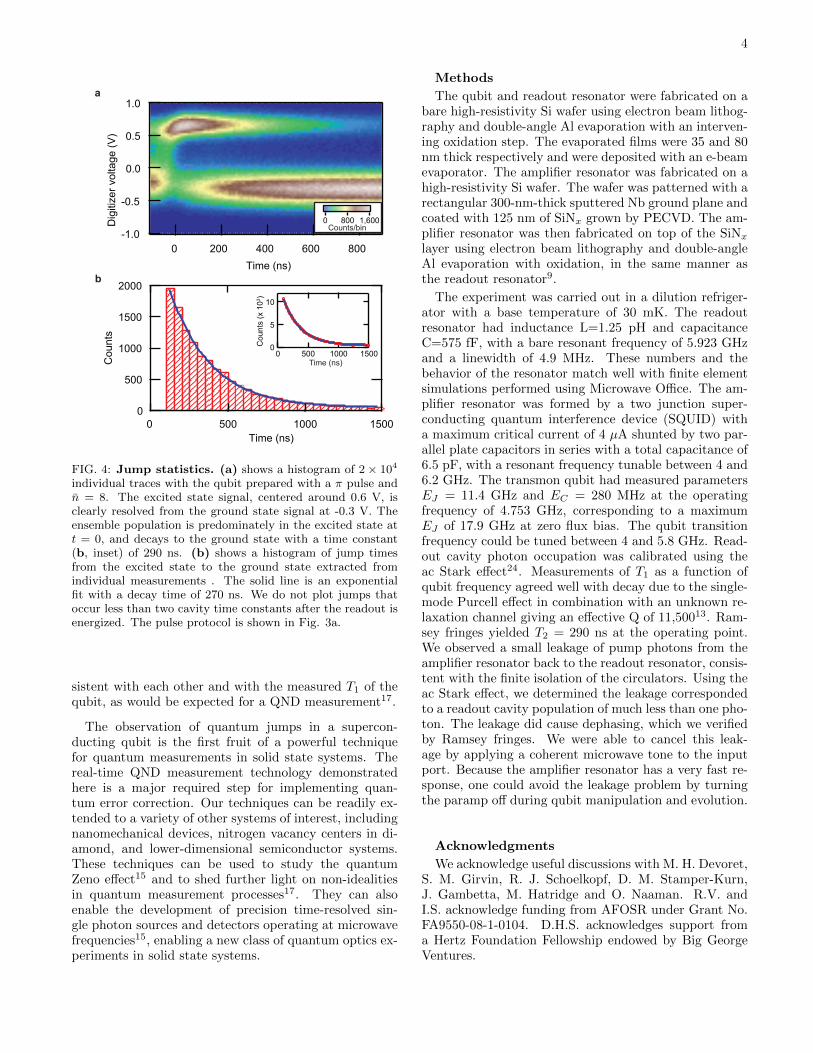
Finally, we look at the statistics of these quantumjumps. Fig. 4a plots a histogram of 2 × 10⁴ individ-ual measurements with the qubit prepared in the excitedstate, as a function of digitizer voltage and time (see Sup-plementary Video 1 which shows the evolution of the his-togram as a function of qubit rabi drive strength). Mostof the population is measured in the excited state (pos-itive voltage) at t = 0 and then decays to the groundstate (negative voltage) with a time constant of 290 ns(Fig. 4b, inset). Despite the large separation betweenthe ground and excited state peaks, the maximum qubitreadout fidelity is about 70%. This can be almost en-tirely attributed to the lifetime of the qubit (290 ns) beingcomparable to the cavity rise time (66 ns)14, which meansthat around 30% of the excited state population decays tothe ground state before the measurement is made. Sincewe can resolve individual decay events, we can also plota histogram of the jump (excited to ground state) timesas shown in Fig. 4b (see Supplementary Video 2 whichshows the evolution of this histogram as it builds up).The histogram shows an exponential decay with a timeconstant of 270 ns. Both these time constants are con-
4
2000
1500
1000
500
0
Cou
nts
150010005000Time (ns)
10
5
0
150010005000
Cou
nts
(x 1
03 )
Time (ns)
a
-1.0
-0.5
0.0
0.5
1.0D
igiti
zer v
olta
ge (V
)
8006004002000
0 800 1,600Counts/bin
Time (ns)b
FIG. 4: Jump statistics. (a) shows a histogram of 2 × 10⁴
individual traces with the qubit prepared with a π pulse andn̄ = 8. The excited state signal, centered around 0.6 V, isclearly resolved from the ground state signal at -0.3 V. Theensemble population is predominately in the excited state att = 0, and decays to the ground state with a time constant(b, inset) of 290 ns. (b) shows a histogram of jump timesfrom the excited state to the ground state extracted fromindividual measurements . The solid line is an exponentialfit with a decay time of 270 ns. We do not plot jumps thatoccur less than two cavity time constants after the readout isenergized. The pulse protocol is shown in Fig. 3a.
sistent with each other and with the measured T1 of thequbit, as would be expected for a QND measurement17.
The observation of quantum jumps in a supercon-ducting qubit is the first fruit of a powerful techniquefor quantum measurements in solid state systems. Thereal-time QND measurement technology demonstratedhere is a major required step for implementing quan-tum error correction. Our techniques can be readily ex-tended to a variety of other systems of interest, includingnanomechanical devices, nitrogen vacancy centers in di-amond, and lower-dimensional semiconductor systems.These techniques can be used to study the quantumZeno effect15 and to shed further light on non-idealitiesin quantum measurement processes17. They can alsoenable the development of precision time-resolved sin-gle photon sources and detectors operating at microwavefrequencies15, enabling a new class of quantum optics ex-periments in solid state systems.
Methods
The qubit and readout resonator were fabricated on abare high-resistivity Si wafer using electron beam lithog-raphy and double-angle Al evaporation with an interven-ing oxidation step. The evaporated films were 35 and 80nm thick respectively and were deposited with an e-beamevaporator. The amplifier resonator was fabricated on ahigh-resistivity Si wafer. The wafer was patterned with arectangular 300-nm-thick sputtered Nb ground plane andcoated with 125 nm of SiNx grown by PECVD. The am-plifier resonator was then fabricated on top of the SiNx
layer using electron beam lithography and double-angleAl evaporation with oxidation, in the same manner asthe readout resonator9.
The experiment was carried out in a dilution refriger-ator with a base temperature of 30 mK. The readoutresonator had inductance L=1.25 pH and capacitanceC=575 fF, with a bare resonant frequency of 5.923 GHzand a linewidth of 4.9 MHz. These numbers and thebehavior of the resonator match well with finite elementsimulations performed using Microwave Office. The am-plifier resonator was formed by a two junction super-conducting quantum interference device (SQUID) witha maximum critical current of 4 µA shunted by two par-allel plate capacitors in series with a total capacitance of6.5 pF, with a resonant frequency tunable between 4 and6.2 GHz. The transmon qubit had measured parametersEJ = 11.4 GHz and EC = 280 MHz at the operatingfrequency of 4.753 GHz, corresponding to a maximumEJ of 17.9 GHz at zero flux bias. The qubit transitionfrequency could be tuned between 4 and 5.8 GHz. Read-out cavity photon occupation was calibrated using theac Stark effect24. Measurements of T1 as a function ofqubit frequency agreed well with decay due to the single-mode Purcell effect in combination with an unknown re-laxation channel giving an effective Q of 11,50013. Ram-sey fringes yielded T2 = 290 ns at the operating point.We observed a small leakage of pump photons from theamplifier resonator back to the readout resonator, consis-tent with the finite isolation of the circulators. Using theac Stark effect, we determined the leakage correspondedto a readout cavity population of much less than one pho-ton. The leakage did cause dephasing, which we verifiedby Ramsey fringes. We were able to cancel this leak-age by applying a coherent microwave tone to the inputport. Because the amplifier resonator has a very fast re-sponse, one could avoid the leakage problem by turningthe paramp off during qubit manipulation and evolution.
Acknowledgments
We acknowledge useful discussions with M. H. Devoret,S. M. Girvin, R. J. Schoelkopf, D. M. Stamper-Kurn,J. Gambetta, M. Hatridge and O. Naaman. R.V. andI.S. acknowledge funding from AFOSR under Grant No.FA9550-08-1-0104. D.H.S. acknowledges support froma Hertz Foundation Fellowship endowed by Big GeorgeVentures.
5
Author ContributionsD.H.S. and R.V. designed the samples. D.H.S. fabri-
cated the samples. R.V. and D.H.S. performed the ex-
periments, analyzed the data, and wrote the manuscript.All work was carried out under the supervision of I.S.
1 Nagourney, W., Sandberg, J. & Dehmelt, H. Shelved op-tical electron amplifier: Observation of quantum jumps.Phys. Rev. Lett. 56, 2797–2799 (1986).
2 Bergquist, J. C., Hulet, R. G., Itano, W. M. & Wineland,D. J. Observation of quantum jumps in a single atom.Phys. Rev. Lett. 57, 1699–1702 (1986).
3 Sauter, T., Neuhauser, W., Blatt, R. & Toschek, P. E.Observation of quantum jumps. Phys. Rev. Lett. 57, 1696–1698 (1986).
4 Basche, T., Kummer, S. & Brauchle, C. Direct spectro-scopic observation of quantum jumps of a single molecule.Nature 373, 132–134 (1995).
5 Gleyzes, S. et al. Quantum jumps of light recording thebirth and death of a photon in a cavity. Nature 446, 297–300 (2007).
6 Peil, S. & Gabrielse, G. Observing the quantum limit ofan electron cyclotron: QND measurements of quantumjumps between Fock states. Phys. Rev. Lett. 83, 1287–1290 (1999).
7 Clarke, J. & Wilhelm, F. K. Superconducting quantumbits. Nature 453, 1031–1042 (2008).
8 Wallraff, A. et al. Strong coupling of a single photon toa superconducting qubit using circuit quantum electrody-namics. Nature 431, 162–167 (2004).
9 Hatridge, M., Vijay, R., Slichter, D. H., Clarke, J. & Sid-diqi, I. Dispersive magnetometry with a quantum lim-ited SQUID parametric amplifier (2010). URL http:
//arxiv.org/abs/1003.2466v1.10 Ahn, C., Doherty, A. C. & Landahl, A. J. Continuous
quantum error correction via quantum feedback control.Phys. Rev. A 65, 042301 (2002).
11 Braginsky, V. B. & Khalili, F. Y. Quantum nondemolitionmeasurements: the route from toys to tools. Rev. Mod.Phys. 68, 1 (1996).
12 Blais, A., Huang, R.-S., Wallraff, A., Girvin, S. M. &Schoelkopf, R. J. Cavity quantum electrodynamics for su-perconducting electrical circuits: An architecture for quan-tum computation. Phys. Rev. A 69, 062320 (2004).
13 Houck, A. A. et al. Controlling the spontaneous emission ofa superconducting transmon qubit. Phys. Rev. Lett. 101,080502 (2008).
14 Wallraff, A. et al. Approaching unit visibility for controlof a superconducting qubit with dispersive readout. Phys.Rev. Lett. 95, 060501 (2005).
15 Gambetta, J. et al. Quantum trajectory approach to cir-cuit QED: Quantum jumps and the Zeno effect. Phys. Rev.A 77, 012112 (2008).
16 Manucharyan, V. E., Koch, J., Glazman, L. I. & Devoret,M. H. Fluxonium: Single Cooper-pair circuit free of chargeoffsets. Science 326, 113–116 (2009).
17 Boissonneault, M., Gambetta, J. M. & Blais, A. Dispersiveregime of circuit QED: Photon-dependent qubit dephasingand relaxation rates. Phys. Rev. A 79, 013819 (2009).
18 Mallet, F. et al. Single-shot qubit readout in circuit quan-tum electrodynamics. Nature Phys. 5, 791–795 (2009).
19 Martinis, J. M. Superconducting phase qubits. Quant.Info. Proc. 8, 81–103 (2009).
20 Castellanos-Beltran, M. A. & Lehnert, K. W. Widelytunable parametric amplifier based on a superconductingquantum interference device array resonator. Appl. Phys.Lett. 91, 083509 (2007).
21 Bergeal, N. et al. Phase-preserving amplification near thequantum limit with a Josephson ring modulator. Nature465, 64–68 (2010).
22 Koch, J. et al. Charge-insensitive qubit design derived fromthe Cooper pair box. Phys. Rev. A 76, 042319 (2007).
23 Vijay, R., Devoret, M. H. & Siddiqi, I. Invited reviewarticle: The Josephson bifurcation amplifier. Rev. Sci. In-strum. 80, 111101 (2009).
24 Schuster, D. I. et al. AC stark shift and dephasing of asuperconducting qubit strongly coupled to a cavity field.Phys. Rev. Lett. 94, 123602 (2005).
25 Itano, W. M., Heinzen, D. J., Bollinger, J. J. & Wineland,D. J. Quantum Zeno effect. Phys. Rev. A 41, 2295–2300(1990).

Supplement to “Observation of quantum jumps in a superconducting artificial atom”
R. Vijay∗, D. H. Slichter∗, and I. SiddiqiQuantum Nanoelectronics Laboratory, Department of Physics, University of California, Berkeley CA 94720
(Dated: September 16, 2010)
I. DETAILS OF AMPLIFICATIONMECHANISM
bistable(fc,Pc)
Pum
p po
wer
Pump frequency
paramp
a
Pum
p ph
ase
Pump power
b+90o
-90o
FIG. S1: The phase diagram of the amplifier resonator isshown schematically in (a). The resonance frequency (solidline) gradually decreases with increasing drive power. Abovea critical drive power PC and below a critical frequency fCthe resonator is bistable. At powers slightly below PC , theresonator functions as a parametric amplifier (paramp). (b)shows a linecut of (a) at constant pump frequency in theparamp regime. A weak signal modulating the drive powerleads to large changes in the reflected phase of the pump.
The phase diagram of our non-linear resonator is shownschematically in Fig. S1a. The solid line indicates the
effective resonant frequency as a function of bias fre-quency and power. For drive power P > PC and drivefrequency f < fC , the system is bistable within theboundary indicated by the dotted lines. This bistabil-ity has been employed for qubit readout in the past1,2.In this work, we bias the resonator just outside thebistable regime. This bias region, marked as “paramp”in Fig. S1a, has been accessed to demonstrate paramet-ric amplification3–5. Fig. S1b explains the principle ofsmall signal degenerate parametric amplification. Thereflected pump phase is plotted as a function of pumppower, giving the transfer function of the amplifier. Aweak input signal is combined with the pump and mod-ulates its amplitude, resulting in a large change in thephase of the reflected pump. Since there are many morepump photons than signal photons, this effectively am-plifies the input signal.
Two key points should be noted here. First, this tech-nique implements a phase-sensitive amplifier6, since onlysignals in phase with the pump will be amplified. Sec-ondly, the amplifier is linear only for input signals whichkeep the bias conditions in the linear region of the trans-fer function shown in Fig. S1a. However, in this work weare only concerned with two possible cavity states corre-sponding to the two states of the qubit. Therefore, thelinearity of the amplifier is inconsequential here as longas it faithfully maps the two cavity states to two distinctoutput states.
1 Vijay, R., Devoret, M. H. & Siddiqi, I. Invited review arti-cle: The josephson bifurcation amplifier. Rev. Sci. Instrum.80, 111101 (2009).
2 Mallet, F. et al. Single-shot qubit readout in circuit quan-tum electrodynamics. Nature Phys. 5, 791–795 (2009).
3 Castellanos-Beltran, M. A. & Lehnert, K. W. Widely tun-able parametric amplifier based on a superconducting quan-tum interference device array resonator. Appl. Phys. Lett.91, 083509 (2007).
4 Vijay, R. Josephson Bifurcation Amplifier: Amplifying
quantum signals using a dynamical bifurcation. Ph.D. the-sis, Yale University (2008).
5 Hatridge, M., Vijay, R., Slichter, D. H., Clarke, J. & Siddiqi,I. Dispersive magnetometry with a quantum limited squidparametric amplifier (2010). URL http://arxiv.org/abs/
1003.2466v1.6 Caves, C. M. Quantum limits on noise in linear amplifiers.
Phys. Rev. D 26, 1817–1839 (1982).
arX
iv:1
009.
2969
v1 [
cond
-mat
.mes
-hal
l] 1
5 Se
p 20
10