Embed Size (px)
Citation preview
QUCM Elliott Flow Computer Application Manual
QUCM Elliott Flow ComputerInstallation and Programming Manual
This Manual describes the QUCM application for interfacing an Elliott Flow Computer to a Modbus/TCP system.
Effective: 27 July, 2001
Niobrara Research & Development CorporationP.O. Box 3418 Joplin, MO 64803 USA
Telephone: (800) 235-6723 or (417) 624-8918Facsimile: (417) 624-8920www.niobrara.com

POWERLOGIC, SY/MAX, and Square D are registered trademarks of Square D Com-pany.
Subject to change without notice.
© Niobrara Research & Development Corporation 2000, 2001. All Rights Reserved.
3
Contents
1 Introduction .........................................................................................................................5
2 Installation .............................................................................................................................7
Module Installation .........................................................................................................7Software Installation .......................................................................................................7Serial Connections to the QUCM-LE ............................................................................7
Port 1 to Elliott Flow Computer ..............................................................................7Port 2 to the Personal Computer .............................................................................8
Loading the Applications into the QUCM .....................................................................9
3 Modbus/TCP Operation............................................................................................11
Slave Address ...............................................................................................................11Register List .................................................................................................................11
General Status Registers........................................................................................11Current Data ..........................................................................................................1212AM Data ............................................................................................................15Latest Proof Data ...................................................................................................19Download Meter Factor ........................................................................................29
4 Web Server.........................................................................................................................31
Main Page .....................................................................................................................31Current Data Page ........................................................................................................3212AM Data Page ..........................................................................................................33Configure QUCM .........................................................................................................34
Change Elliott Master/Prover Address ..................................................................36Serial Port Configuration ......................................................................................36Save Settings to FLASH .......................................................................................37
Elliott Control ...............................................................................................................37Statistics Page ...............................................................................................................38
Figures
Figure 2-1 QUCM-LE to RS-232 Port (Screw Terminal) (CS215 Cable) ....................................8
Figure 2-2 QUCM-LE Layout ........................................................................................................8
4
Figure 2-3 QUCM-LE to RS-232 PC DCE Port (9-pin) (MM1 Cable) .......................................9
Figure 4-1 Main Web Page ...........................................................................................................32
Figure 4-2 Web Server Current Data Page ...................................................................................33
Figure 4-3 Web Server 12AM Data Page .....................................................................................34
Figure 4-4 Enter Password Page ...................................................................................................35
Figure 4-5 Configuration Page .....................................................................................................35
Figure 4-6 Elliott Slave Address ..................................................................................................36
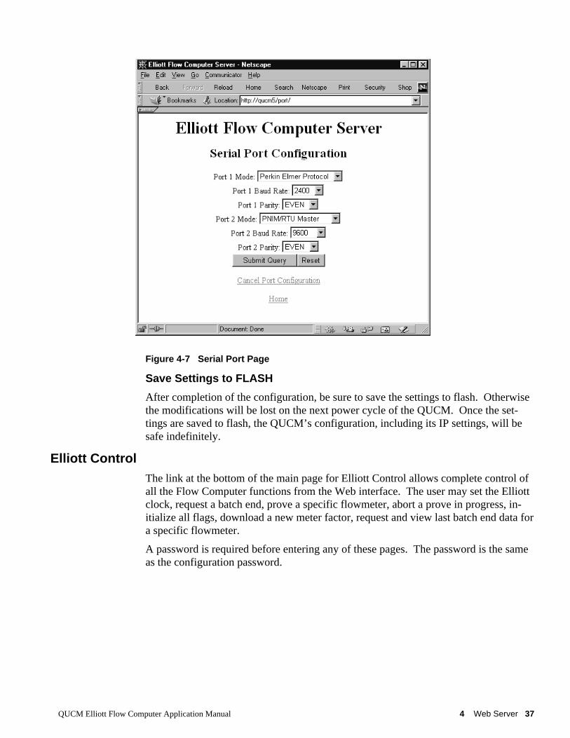
Figure 4-7 Serial Port Page ...........................................................................................................37
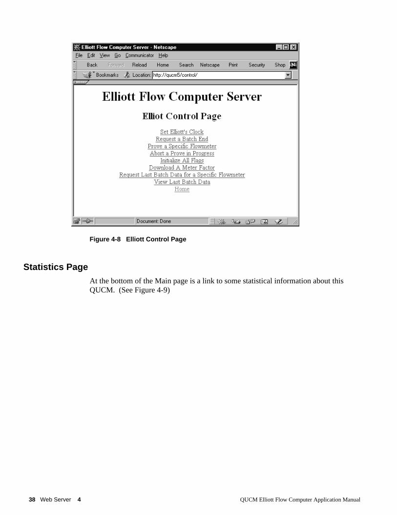
Figure 4-8 Elliott Control Page ....................................................................................................38
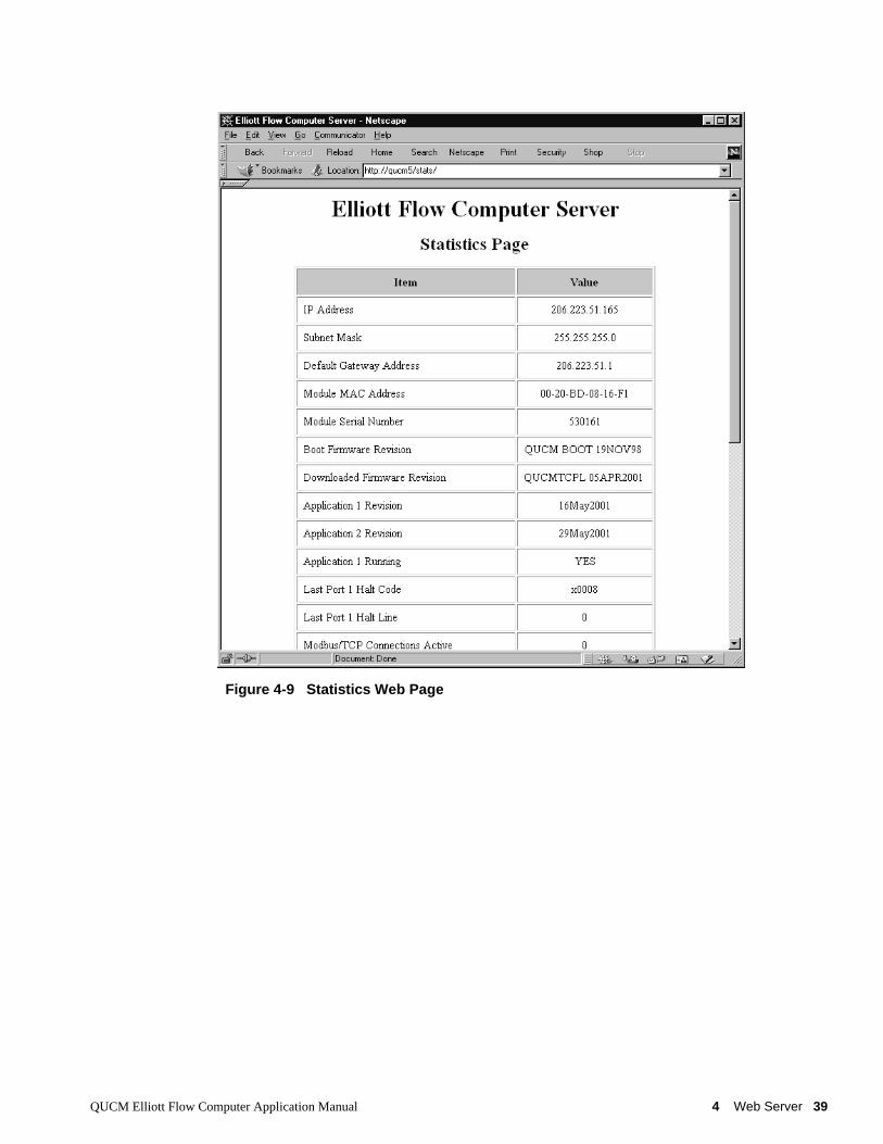
Figure 4-9 Statistics Web Page.....................................................................................................39
Tables
Table 3-1 General Status Register List .........................................................................................12
Table 3-2 Type A Current Data (N=1 to 15) ................................................................................13
Table 3-3 Type B Current Data (N=1 to 15) ................................................................................14
Table 3-4 Type A 12AM Data (N=1 to 15) ..................................................................................16
Table 3-5 Type B 12AM Data Block (N=1 through 15) ..............................................................18
Table 3-6 Latest Proof Data .........................................................................................................19
Table 3-7 Latest Proof Data (Runs 1 through 5) ..........................................................................20
Table 3-8 Clock Set ......................................................................................................................21
Table 3-9 Request Batch End .......................................................................................................22
Table 3-10 Prove A Specific Flowmeter ......................................................................................23
Table 3-11 Abort Prove in Progress .............................................................................................24
Table 3-12 Initialize All Flags ......................................................................................................25
Table 3-13 Request Last Batch End Data .....................................................................................26
Table 3-14 Type A Last Batch Data .............................................................................................27
Table 3-15 Type A Last Batch Reverse Data ...............................................................................28
Table 3-16 Type B Last Batch End Data Block ...........................................................................29
Table 3-17 Download Meter Factor .............................................................................................30
QUCM Elliott Flow Computer Application Manual 1 Introduction 5
1
Introduction
The Niobrara QUCM is a TSX Quantum® compatible module that is capable of run-ning multiple applications for performing communication translations between serialprotocols. This document covers an application that allows an Elliott Master/ProverComputer to be accessed as a Modbus/TCP compatible device. The QUCM emulatesa Perkin Elmer Computer to have controlling access to the flow computer data.
Two applications are required to be loaded into the QUCM: app1.qcm is the ElliottFlow Computer serial driver and Modbus/TCP server, app2.qcm is the web serverused for configuration and data display. Both of these applications must be runningfor the system to properly perform.
Port 1 of the QUCM is to be connected with an RS-232 cable to the Elliott Mas-ter/Prover Computer. The Elliott Flow Computer provides an ASCII serial interfaceto up to 15 flow computers. The data is accessed via Modbus/TCP by selecting theDestination Index 1.
Port 2 may be configured as a combination PNIM/Modbus RTU master to support astring of PowerLogic and/or Modbus RTU slaves. Up to 32 slaves may attached tothe QUCM. They must be assigned unique drop numbers between 1 and 32. Thesedevices are accessed by Modbus/TCP Destination Indices 101 through 132.
A Modicon two (or more) slot Quantum rack and appropriate Quantum power supplyis needed for mounting the QUCM.
The QUCM-LE will support up to 6 simultaneous Modbus/TCP clients for access tothe Elliott Flow Computer data and PowerLogic/Modbus data.

QUCM Elliott Flow Computer Application Manual 2 Installation 7
2
Installation
Module Installation1 Mount the QUCM in an available slot in the register rack. Secure the screw at the
bottom of the module.
Software InstallationThe application files for the QUCM are included in the ELLIOTT.ZIP file. This filemust be unzipped using PKUNZIP.EXE. A copy of PKUNZIP is included on thestandard NR&D software disk and is also available at www.niobrara.com. The latestversion of the ELLIOTT.ZIP file is located at
http://www.niobrara.com/ftp/qucm/elliott/elliott.zip
The latest version of this document in pdf format is located at:
http://www.niobrara.com/ftp/qucm/elliott/elliott.pdf
Serial Connections to the QUCM-LE
Port 1 to Elliott Flow Computer
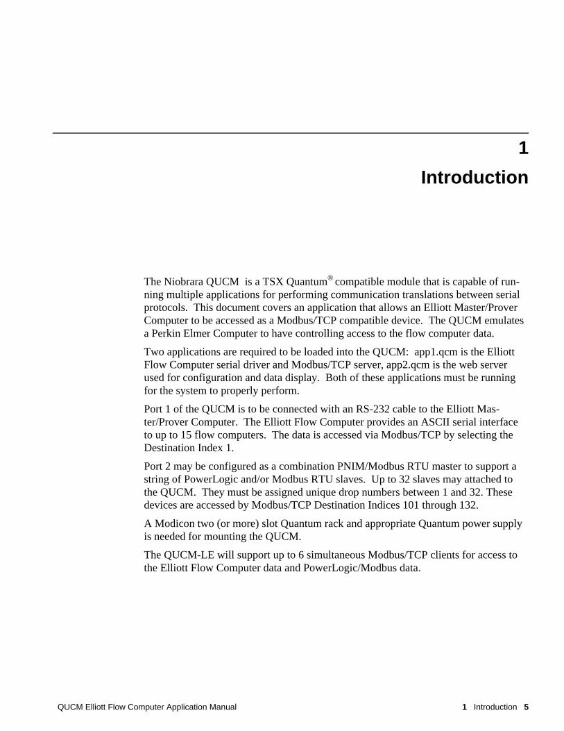
Port 1 of the QUCM-LE is set to RS-232 so a simple cable is required to connect tothe Elliott Flow Computer. Use the Niobrara CS215 cable to connect the QUCM-LEto the Elliott Flow Computer (See Figure 2-1).
8 Installation 2 QUCM Elliott Flow Computer Application Manual
Figure 2-1 QUCM-LE to RS-232 Port (Screw Terminal) (CS215 Cable)
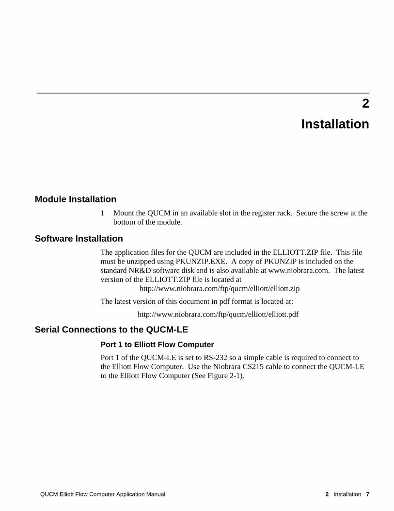
Figure 2-2 QUCM-LE Layout
Port 2 to the Personal Computer
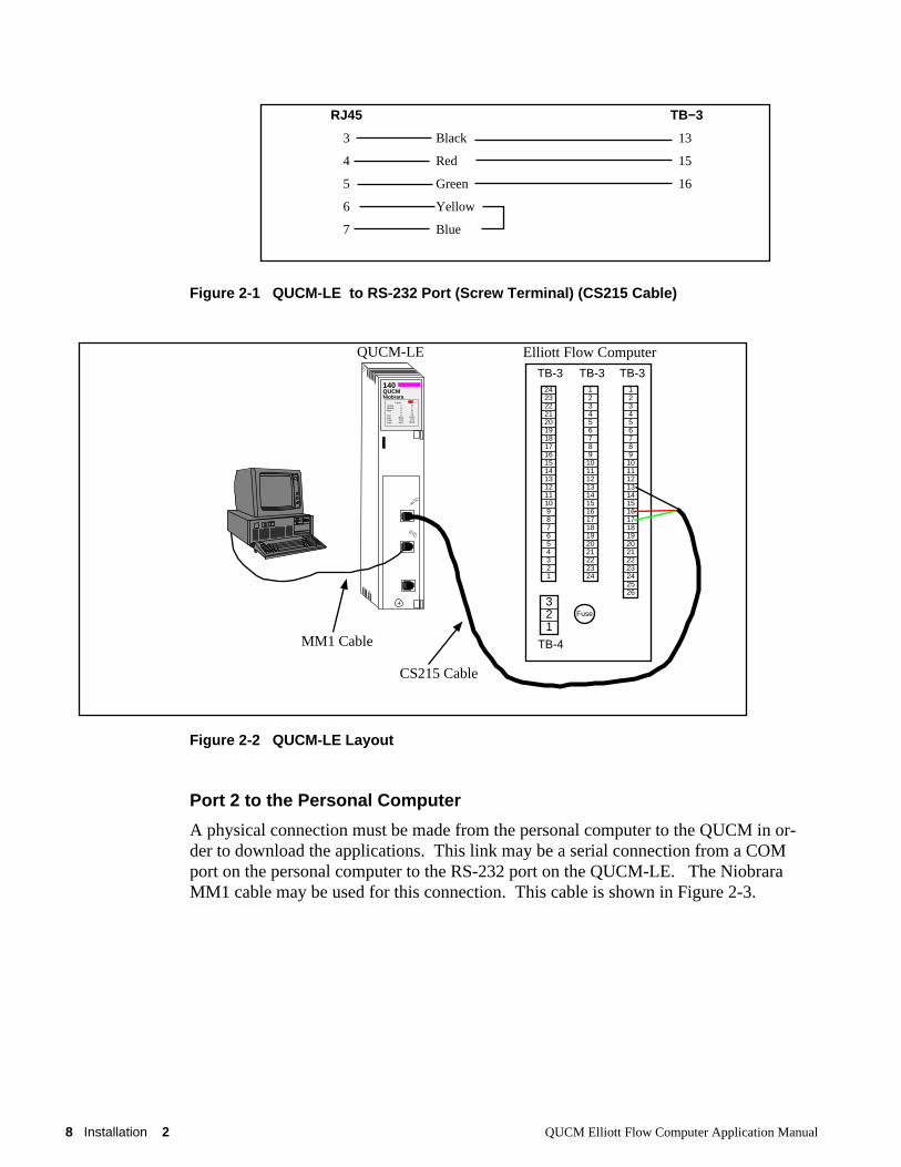
A physical connection must be made from the personal computer to the QUCM in or-der to download the applications. This link may be a serial connection from a COMport on the personal computer to the RS-232 port on the QUCM-LE. The NiobraraMM1 cable may be used for this connection. This cable is shown in Figure 2-3.
RJ45 TB−3
3 Black 13
4 Red 15
5 Green 16
6 Yellow
7 Blue
QUCM-LE
MM1 Cable
CS215 Cable
140QUCMNiobrara
ActiveReadyRun
ColLnkTXERXE
12345
RN1TX1RX1
6789
10RN2TX2RX2
Fault
123456789
1011121314151617181920212223242526
TB-3123456789
101112131415161718192021222324
TB-3242322212019181716151413121110987654321
TB-3
321
TB-4
Fuse
Elliott Flow Computer
QUCM Elliott Flow Computer Application Manual 2 Installation 9
Figure 2-3 QUCM-LE to RS-232 PC DCE Port (9-pin) (MM1 Cable)
Loading the Applications into the QUCMThe QUCM is rapidly evolving so be sure to upgrade the firmware in the module be-fore loading the latest version of APP1.QCC. Most likely the QCOMPILE.EXE hasbeen updated so be sure to use the newest version. Firmware upload is as follows:
1 Remove the module form the rack.
2 Move the RUN/LOAD switch on the back of the module to LOAD.
3 Replace the module in the rack and apply power.
4 Only the 3 light should be on. (The Link and RX E-net lights may be on if theE-net port is connected and there is traffic.)
5 Connect the PC to QUCM Port 1 with a MM1 cable.
6 From the command line enter> fwload qucmtcpl.fwl com1:
Be sure to have the colon after the PC’s com port name. The download will onlytake a few minutes and will inform when finished.
7 Remove the module from the rack and change the switch back to RUN.
8 It is a good idea to press the RESET button after a firmware change.
It is recommended to use the Ethernet capabilities of QLOAD to load APP1.QCC andAPP2.QCC into the QUCM. Set up the IP parameters of the module by the followingmethod:
1 Move Switch 1 to Halt.
2 Connect the PC to QUCM Port 1 with a MM1 cable.
3 From the command line enter>zapreg32 com1:9600,e,8,1 255 -b
This will start zapreg32 in Modbus RTU mode to slave address 255. Use the ar-row and Page Up/Down keys to move to register 46. The IP parameters are shownbelow for a unit with the IP = 206.223.51.150 subnet Mask = 255.255.255.0, De-fault Gate = 206.223.51.1, Modbus/TCP port number = 503, Telnet Port number =24:
Register DescriptionExample (decimal)
RJ45 DE9S (female)
3 2
4 3
5 5
6 4
7 6
7
8
10 Installation 2 QUCM Elliott Flow Computer Application Manual
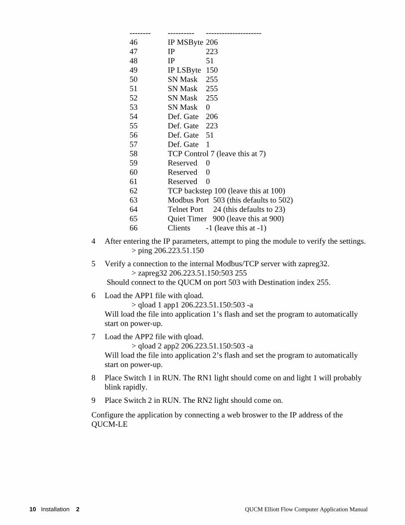
-------- ---------- ---------------------46 IP MSByte 20647 IP 22348 IP 5149 IP LSByte 15050 SN Mask 25551 SN Mask 25552 SN Mask 25553 SN Mask 054 Def. Gate 20655 Def. Gate 22356 Def. Gate 5157 Def. Gate 158 TCP Control 7 (leave this at 7)59 Reserved 060 Reserved 061 Reserved 062 TCP backstep 100 (leave this at 100)63 Modbus Port 503 (this defaults to 502)64 Telnet Port 24 (this defaults to 23)65 Quiet Timer 900 (leave this at 900)66 Clients -1 (leave this at -1)
4 After entering the IP parameters, attempt to ping the module to verify the settings. > ping 206.223.51.150
5 Verify a connection to the internal Modbus/TCP server with zapreg32. > zapreg32 206.223.51.150:503 255
Should connect to the QUCM on port 503 with Destination index 255.
6 Load the APP1 file with qload. > qload 1 app1 206.223.51.150:503 -a
Will load the file into application 1’s flash and set the program to automaticallystart on power-up.
7 Load the APP2 file with qload. > qload 2 app2 206.223.51.150:503 -a
Will load the file into application 2’s flash and set the program to automaticallystart on power-up.
8 Place Switch 1 in RUN. The RN1 light should come on and light 1 will probablyblink rapidly.
9 Place Switch 2 in RUN. The RN2 light should come on.
Configure the application by connecting a web broswer to the IP address of theQUCM-LE
QUCM Elliott Flow Computer Application Manual 3 Modbus/TCP Operation 11
3
Modbus/TCP Operation
Slave AddressThe QUCM serves the Elliott data on Modbus Slave Address 1. The QUCM will al-ways respond to slave address 1; even if it cannot communicate with the Elliott com-puter. The QUCM provides communication status registers that indicate the state ofthe flow computer.
The QUCM optionally supports a network of POWERLOGIC and/or Modbus RTUslaves on port 2. These devices are addressed as Modbus/TCP slaves 101 through132. The QUCM subtracts 100 from the slave address before it transmits the message. Therefore, address the slaves as devices 1 through 32.
Register ListThe data from the Elliott device is presented as Modbus Holding Registers (4x). Modbus function codes 03 and 100 for reading and opcodes 6 and 16 for writes.
Most data is presented as signed 16-bit integers. Values with two holding registers are32-bit integers where the first register is bits 0-15 and the second register is bits 16-31. Many items have implied fixed decimal places and are indicated by notes of (times1000) for example.
Unused registers are returned with the hex value x8000.
General Status Registers
The General Status registers are located in 4x registers 1, 2, and 3 and repeated at reg-isters 997, 998, 999, and 1997, 1998, 1999, and 2997, 2998, 2999.
12 Modbus/TCP Operation 3 QUCM Elliott Flow Computer Application Manual
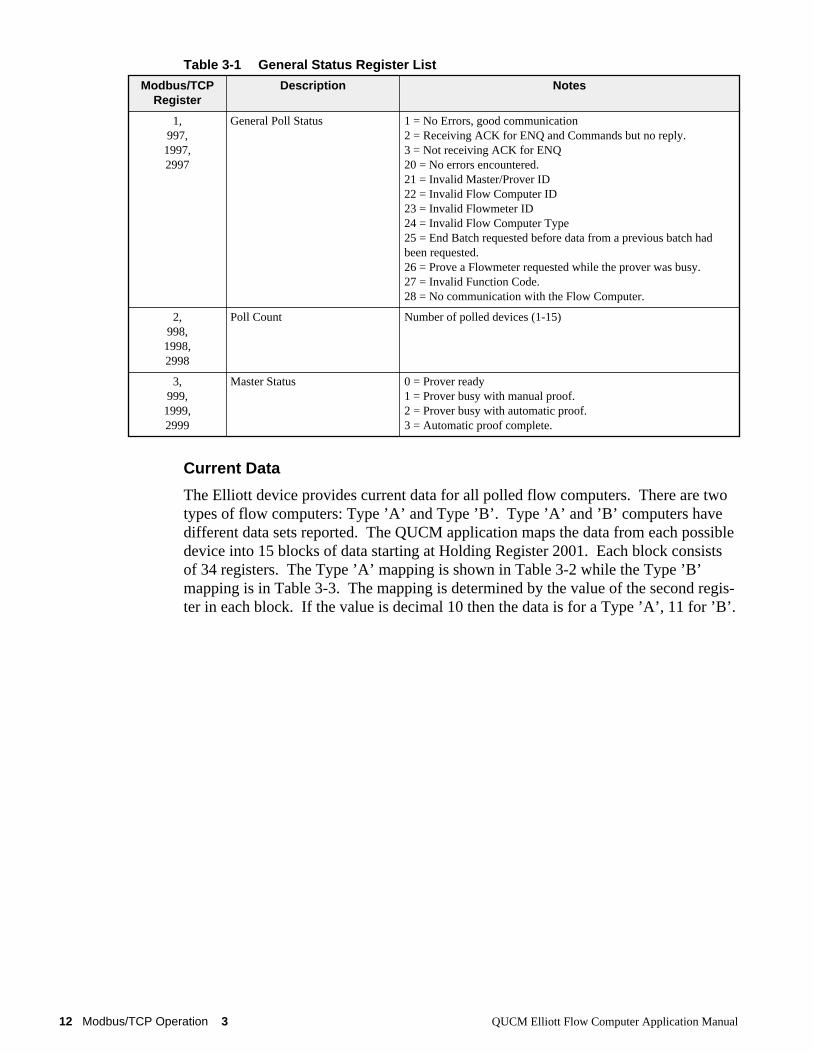
Table 3-1 General Status Register List
Current Data
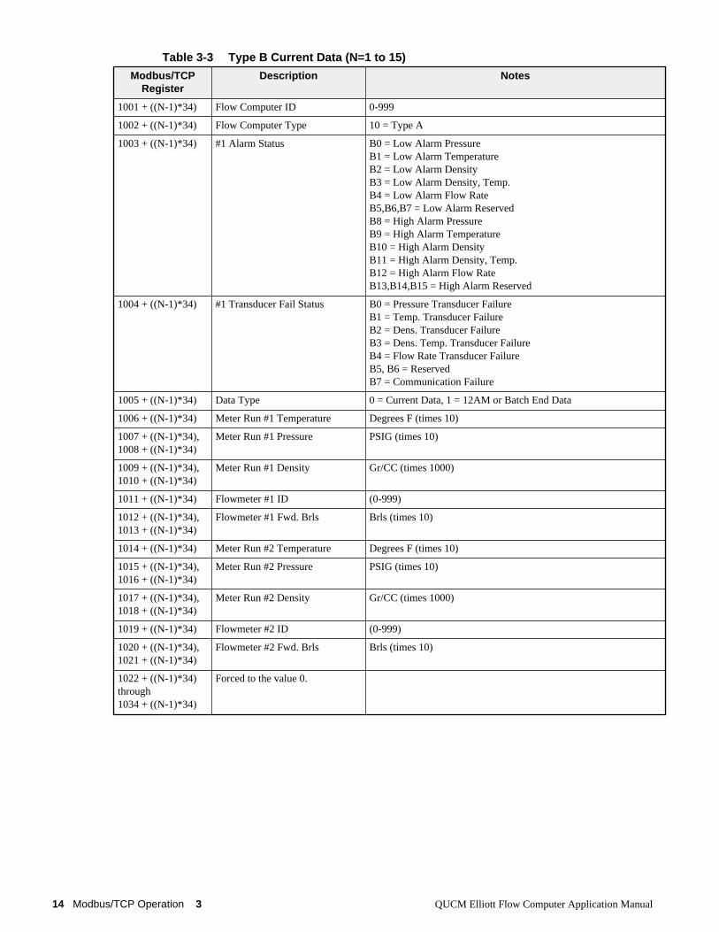
The Elliott device provides current data for all polled flow computers. There are twotypes of flow computers: Type ’A’ and Type ’B’. Type ’A’ and ’B’ computers havedifferent data sets reported. The QUCM application maps the data from each possibledevice into 15 blocks of data starting at Holding Register 2001. Each block consistsof 34 registers. The Type ’A’ mapping is shown in Table 3-2 while the Type ’B’mapping is in Table 3-3. The mapping is determined by the value of the second regis-ter in each block. If the value is decimal 10 then the data is for a Type ’A’, 11 for ’B’.
Modbus/TCPRegister
Description Notes
1,997,1997,2997
General Poll Status 1 = No Errors, good communication2 = Receiving ACK for ENQ and Commands but no reply.3 = Not receiving ACK for ENQ20 = No errors encountered.21 = Invalid Master/Prover ID22 = Invalid Flow Computer ID23 = Invalid Flowmeter ID24 = Invalid Flow Computer Type25 = End Batch requested before data from a previous batch hadbeen requested.26 = Prove a Flowmeter requested while the prover was busy.27 = Invalid Function Code.28 = No communication with the Flow Computer.
2,998,1998,2998
Poll Count Number of polled devices (1-15)
3,999,1999,2999
Master Status 0 = Prover ready1 = Prover busy with manual proof.2 = Prover busy with automatic proof.3 = Automatic proof complete.
QUCM Elliott Flow Computer Application Manual 3 Modbus/TCP Operation 13
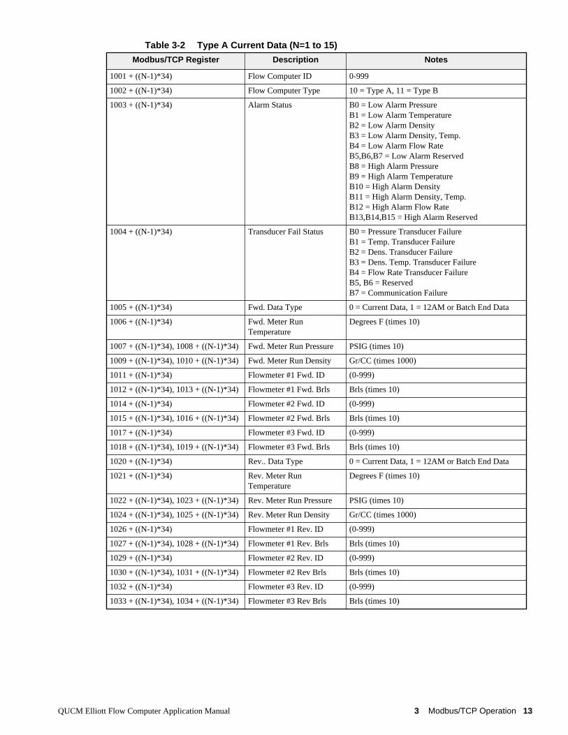
Table 3-2 Type A Current Data (N=1 to 15)
Modbus/TCP Register Description Notes
1001 + ((N-1)*34) Flow Computer ID 0-999
1002 + ((N-1)*34) Flow Computer Type 10 = Type A, 11 = Type B
1003 + ((N-1)*34) Alarm Status B0 = Low Alarm PressureB1 = Low Alarm TemperatureB2 = Low Alarm DensityB3 = Low Alarm Density, Temp.B4 = Low Alarm Flow RateB5,B6,B7 = Low Alarm ReservedB8 = High Alarm PressureB9 = High Alarm TemperatureB10 = High Alarm DensityB11 = High Alarm Density, Temp.B12 = High Alarm Flow RateB13,B14,B15 = High Alarm Reserved
1004 + ((N-1)*34) Transducer Fail Status B0 = Pressure Transducer FailureB1 = Temp. Transducer FailureB2 = Dens. Transducer FailureB3 = Dens. Temp. Transducer FailureB4 = Flow Rate Transducer FailureB5, B6 = ReservedB7 = Communication Failure
1005 + ((N-1)*34) Fwd. Data Type 0 = Current Data, 1 = 12AM or Batch End Data
1006 + ((N-1)*34) Fwd. Meter RunTemperature
Degrees F (times 10)
1007 + ((N-1)*34), 1008 + ((N-1)*34) Fwd. Meter Run Pressure PSIG (times 10)
1009 + ((N-1)*34), 1010 + ((N-1)*34) Fwd. Meter Run Density Gr/CC (times 1000)
1011 + ((N-1)*34) Flowmeter #1 Fwd. ID (0-999)
1012 + ((N-1)*34), 1013 + ((N-1)*34) Flowmeter #1 Fwd. Brls Brls (times 10)
1014 + ((N-1)*34) Flowmeter #2 Fwd. ID (0-999)
1015 + ((N-1)*34), 1016 + ((N-1)*34) Flowmeter #2 Fwd. Brls Brls (times 10)
1017 + ((N-1)*34) Flowmeter #3 Fwd. ID (0-999)
1018 + ((N-1)*34), 1019 + ((N-1)*34) Flowmeter #3 Fwd. Brls Brls (times 10)
1020 + ((N-1)*34) Rev.. Data Type 0 = Current Data, 1 = 12AM or Batch End Data
1021 + ((N-1)*34) Rev. Meter RunTemperature
Degrees F (times 10)
1022 + ((N-1)*34), 1023 + ((N-1)*34) Rev. Meter Run Pressure PSIG (times 10)
1024 + ((N-1)*34), 1025 + ((N-1)*34) Rev. Meter Run Density Gr/CC (times 1000)
1026 + ((N-1)*34) Flowmeter #1 Rev. ID (0-999)
1027 + ((N-1)*34), 1028 + ((N-1)*34) Flowmeter #1 Rev. Brls Brls (times 10)
1029 + ((N-1)*34) Flowmeter #2 Rev. ID (0-999)
1030 + ((N-1)*34), 1031 + ((N-1)*34) Flowmeter #2 Rev Brls Brls (times 10)
1032 + ((N-1)*34) Flowmeter #3 Rev. ID (0-999)
1033 + ((N-1)*34), 1034 + ((N-1)*34) Flowmeter #3 Rev Brls Brls (times 10)
14 Modbus/TCP Operation 3 QUCM Elliott Flow Computer Application Manual
Table 3-3 Type B Current Data (N=1 to 15)
Modbus/TCPRegister
Description Notes
1001 + ((N-1)*34) Flow Computer ID 0-999
1002 + ((N-1)*34) Flow Computer Type 10 = Type A
1003 + ((N-1)*34) #1 Alarm Status B0 = Low Alarm PressureB1 = Low Alarm TemperatureB2 = Low Alarm DensityB3 = Low Alarm Density, Temp.B4 = Low Alarm Flow RateB5,B6,B7 = Low Alarm ReservedB8 = High Alarm PressureB9 = High Alarm TemperatureB10 = High Alarm DensityB11 = High Alarm Density, Temp.B12 = High Alarm Flow RateB13,B14,B15 = High Alarm Reserved
1004 + ((N-1)*34) #1 Transducer Fail Status B0 = Pressure Transducer FailureB1 = Temp. Transducer FailureB2 = Dens. Transducer FailureB3 = Dens. Temp. Transducer FailureB4 = Flow Rate Transducer FailureB5, B6 = ReservedB7 = Communication Failure
1005 + ((N-1)*34) Data Type 0 = Current Data, 1 = 12AM or Batch End Data
1006 + ((N-1)*34) Meter Run #1 Temperature Degrees F (times 10)
1007 + ((N-1)*34),1008 + ((N-1)*34)
Meter Run #1 Pressure PSIG (times 10)
1009 + ((N-1)*34),1010 + ((N-1)*34)
Meter Run #1 Density Gr/CC (times 1000)
1011 + ((N-1)*34) Flowmeter #1 ID (0-999)
1012 + ((N-1)*34),1013 + ((N-1)*34)
Flowmeter #1 Fwd. Brls Brls (times 10)
1014 + ((N-1)*34) Meter Run #2 Temperature Degrees F (times 10)
1015 + ((N-1)*34),1016 + ((N-1)*34)
Meter Run #2 Pressure PSIG (times 10)
1017 + ((N-1)*34),1018 + ((N-1)*34)
Meter Run #2 Density Gr/CC (times 1000)
1019 + ((N-1)*34) Flowmeter #2 ID (0-999)
1020 + ((N-1)*34),1021 + ((N-1)*34)
Flowmeter #2 Fwd. Brls Brls (times 10)
1022 + ((N-1)*34)through 1034 + ((N-1)*34)
Forced to the value 0.

QUCM Elliott Flow Computer Application Manual 3 Modbus/TCP Operation 15
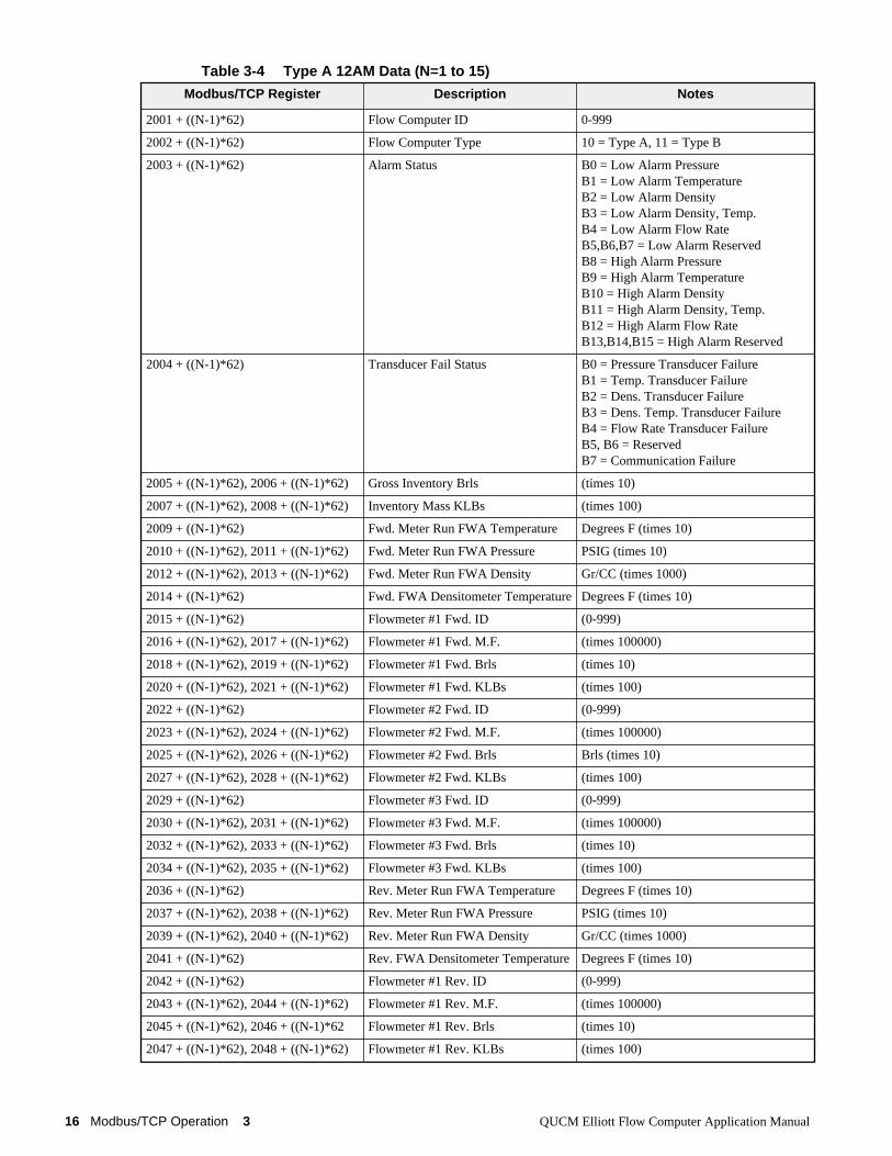
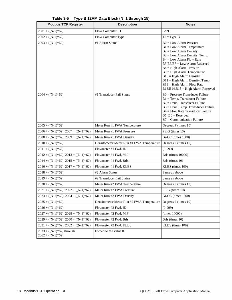
12AM Data
The Elliott device provides 12AM data for all polled flow computers. There are twotypes of flow computers: Type ’A’ and Type ’B’. Type ’A’ and ’B’ computers havedifferent data sets reported. The QUCM application maps the data from each possibledevice into 15 blocks of data starting at Holding Register 2001. Each block consistsof 62 registers. The Type ’A’ mapping is shown in Table 3-4 while the Type ’B’mapping is in Table 3-5. The mapping is determined by the value of the second regis-ter in each block. If the value is decimal 10 then the data is for a Type ’A’, 11 for ’B’.
16 Modbus/TCP Operation 3 QUCM Elliott Flow Computer Application Manual
Table 3-4 Type A 12AM Data (N=1 to 15)
Modbus/TCP Register Description Notes
2001 + ((N-1)*62) Flow Computer ID 0-999
2002 + ((N-1)*62) Flow Computer Type 10 = Type A, 11 = Type B
2003 + ((N-1)*62) Alarm Status B0 = Low Alarm PressureB1 = Low Alarm TemperatureB2 = Low Alarm DensityB3 = Low Alarm Density, Temp.B4 = Low Alarm Flow RateB5,B6,B7 = Low Alarm ReservedB8 = High Alarm PressureB9 = High Alarm TemperatureB10 = High Alarm DensityB11 = High Alarm Density, Temp.B12 = High Alarm Flow RateB13,B14,B15 = High Alarm Reserved
2004 + ((N-1)*62) Transducer Fail Status B0 = Pressure Transducer FailureB1 = Temp. Transducer FailureB2 = Dens. Transducer FailureB3 = Dens. Temp. Transducer FailureB4 = Flow Rate Transducer FailureB5, B6 = ReservedB7 = Communication Failure
2005 + ((N-1)*62), 2006 + ((N-1)*62) Gross Inventory Brls (times 10)
2007 + ((N-1)*62), 2008 + ((N-1)*62) Inventory Mass KLBs (times 100)
2009 + ((N-1)*62) Fwd. Meter Run FWA Temperature Degrees F (times 10)
2010 + ((N-1)*62), 2011 + ((N-1)*62) Fwd. Meter Run FWA Pressure PSIG (times 10)
2012 + ((N-1)*62), 2013 + ((N-1)*62) Fwd. Meter Run FWA Density Gr/CC (times 1000)
2014 + ((N-1)*62) Fwd. FWA Densitometer Temperature Degrees F (times 10)
2015 + ((N-1)*62) Flowmeter #1 Fwd. ID (0-999)
2016 + ((N-1)*62), 2017 + ((N-1)*62) Flowmeter #1 Fwd. M.F. (times 100000)
2018 + ((N-1)*62), 2019 + ((N-1)*62) Flowmeter #1 Fwd. Brls (times 10)
2020 + ((N-1)*62), 2021 + ((N-1)*62) Flowmeter #1 Fwd. KLBs (times 100)
2022 + ((N-1)*62) Flowmeter #2 Fwd. ID (0-999)
2023 + ((N-1)*62), 2024 + ((N-1)*62) Flowmeter #2 Fwd. M.F. (times 100000)
2025 + ((N-1)*62), 2026 + ((N-1)*62) Flowmeter #2 Fwd. Brls Brls (times 10)
2027 + ((N-1)*62), 2028 + ((N-1)*62) Flowmeter #2 Fwd. KLBs (times 100)
2029 + ((N-1)*62) Flowmeter #3 Fwd. ID (0-999)
2030 + ((N-1)*62), 2031 + ((N-1)*62) Flowmeter #3 Fwd. M.F. (times 100000)
2032 + ((N-1)*62), 2033 + ((N-1)*62) Flowmeter #3 Fwd. Brls (times 10)
2034 + ((N-1)*62), 2035 + ((N-1)*62) Flowmeter #3 Fwd. KLBs (times 100)
2036 + ((N-1)*62) Rev. Meter Run FWA Temperature Degrees F (times 10)
2037 + ((N-1)*62), 2038 + ((N-1)*62) Rev. Meter Run FWA Pressure PSIG (times 10)
2039 + ((N-1)*62), 2040 + ((N-1)*62) Rev. Meter Run FWA Density Gr/CC (times 1000)
2041 + ((N-1)*62) Rev. FWA Densitometer Temperature Degrees F (times 10)
2042 + ((N-1)*62) Flowmeter #1 Rev. ID (0-999)
2043 + ((N-1)*62), 2044 + ((N-1)*62) Flowmeter #1 Rev. M.F. (times 100000)
2045 + ((N-1)*62), 2046 + ((N-1)*62 Flowmeter #1 Rev. Brls (times 10)
2047 + ((N-1)*62), 2048 + ((N-1)*62) Flowmeter #1 Rev. KLBs (times 100)

QUCM Elliott Flow Computer Application Manual 3 Modbus/TCP Operation 17
2049 + ((N-1)*62) Flowmeter #2 Rev. ID (0-999)
2050 + ((N-1)*62), 2051 + ((N-1)*62) Flowmeter #2 Rev. M.F. (times 100000)
2052 + ((N-1)*62), 2053 + ((N-1)*62) Flowmeter #2 Rev Brls Brls (times 10)
2054 + ((N-1)*62), 2055 + ((N-1)*62) Flowmeter #2 Rev. KLBs (times 100)
2056 + ((N-1)*62) Flowmeter #3 Rev. ID (0-999)
2057 + ((N-1)*62), 2058 + ((N-1)*62) Flowmeter #3 Rev. M.F. (times 100000)
2059 + ((N-1)*62), 2060 + ((N-1)*62) Flowmeter #3 Rev Brls (times 10)
2061 + ((N-1)*62), 2062 + ((N-1)*62) Flowmeter #3 Rev. KLBs (times 100)
18 Modbus/TCP Operation 3 QUCM Elliott Flow Computer Application Manual
Table 3-5 Type B 12AM Data Block (N=1 through 15)
Modbus/TCP Register Description Notes
2001 + ((N-1)*62) Flow Computer ID 0-999
2002 + ((N-1)*62) Flow Computer Type 11 = Type B
2003 + ((N-1)*62) #1 Alarm Status B0 = Low Alarm PressureB1 = Low Alarm TemperatureB2 = Low Alarm DensityB3 = Low Alarm Density, Temp.B4 = Low Alarm Flow RateB5,B6,B7 = Low Alarm ReservedB8 = High Alarm PressureB9 = High Alarm TemperatureB10 = High Alarm DensityB11 = High Alarm Density, Temp.B12 = High Alarm Flow RateB13,B14,B15 = High Alarm Reserved
2004 + ((N-1)*62) #1 Transducer Fail Status B0 = Pressure Transducer FailureB1 = Temp. Transducer FailureB2 = Dens. Transducer FailureB3 = Dens. Temp. Transducer FailureB4 = Flow Rate Transducer FailureB5, B6 = ReservedB7 = Communication Failure
2005 + ((N-1)*62) Meter Run #1 FWA Temperature Degrees F (times 10)
2006 + ((N-1)*62), 2007 + ((N-1)*62) Meter Run #1 FWA Pressure PSIG (times 10)
2008 + ((N-1)*62), 2009 + ((N-1)*62) Meter Run #1 FWA Density Gr/CC (times 1000)
2010 + ((N-1)*62) Densitometer Meter Run #1 FWA Temperature Degrees F (times 10)
2011 + ((N-1)*62) Flowmeter #1 Fwd. ID (0-999)
2012 + ((N-1)*62), 2013 + ((N-1)*62) Flowmeter #1 Fwd. M.F. Brls (times 10000)
2014 + ((N-1)*62), 2015 + ((N-1)*62) Flowmeter #1 Fwd. Brls Brls (times 10)
2016 + ((N-1)*62), 2017 + ((N-1)*62) Flowmeter #1 Fwd. KLBS KLBS (times 100)
2018 + ((N-1)*62) #2 Alarm Status Same as above
2019 + ((N-1)*62) #2 Transducer Fail Status Same as above
2020 + ((N-1)*62) Meter Run #2 FWA Temperature Degrees F (times 10)
2021 + ((N-1)*62), 2022 + ((N-1)*62) Meter Run #2 FWA Pressure PSIG (times 10)
2023 + ((N-1)*62), 2024 + ((N-1)*62) Meter Run #2 FWA Density Gr/CC (times 1000)
2025 + ((N-1)*62) Densitometer Meter Run #2 FWA Temperature Degrees F (times 10)
2026 + ((N-1)*62) Flowmeter #2 Fwd. ID (0-999)
2027 + ((N-1)*62), 2028 + ((N-1)*62) Flowmeter #2 Fwd. M.F. (times 10000)
2029 + ((N-1)*62), 2030 + ((N-1)*62) Flowmeter #2 Fwd. Brls Brls (times 10)
2031 + ((N-1)*62), 2032 + ((N-1)*62) Flowmeter #2 Fwd. KLBS KLBS (times 100)
2033 + ((N-1)*62) through 2062 + ((N-1)*62)
Forced to the value 0.
QUCM Elliott Flow Computer Application Manual 3 Modbus/TCP Operation 19
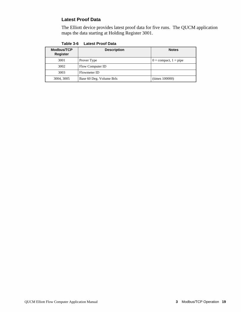
Latest Proof Data
The Elliott device provides latest proof data for five runs. The QUCM applicationmaps the data starting at Holding Register 3001.
Table 3-6 Latest Proof Data
Modbus/TCPRegister
Description Notes
3001 Prover Type 0 = compact, 1 = pipe
3002 Flow Computer ID
3003 Flowmeter ID
3004, 3005 Base 60 Deg. Volume Brls (times 100000)
20 Modbus/TCP Operation 3 QUCM Elliott Flow Computer Application Manual
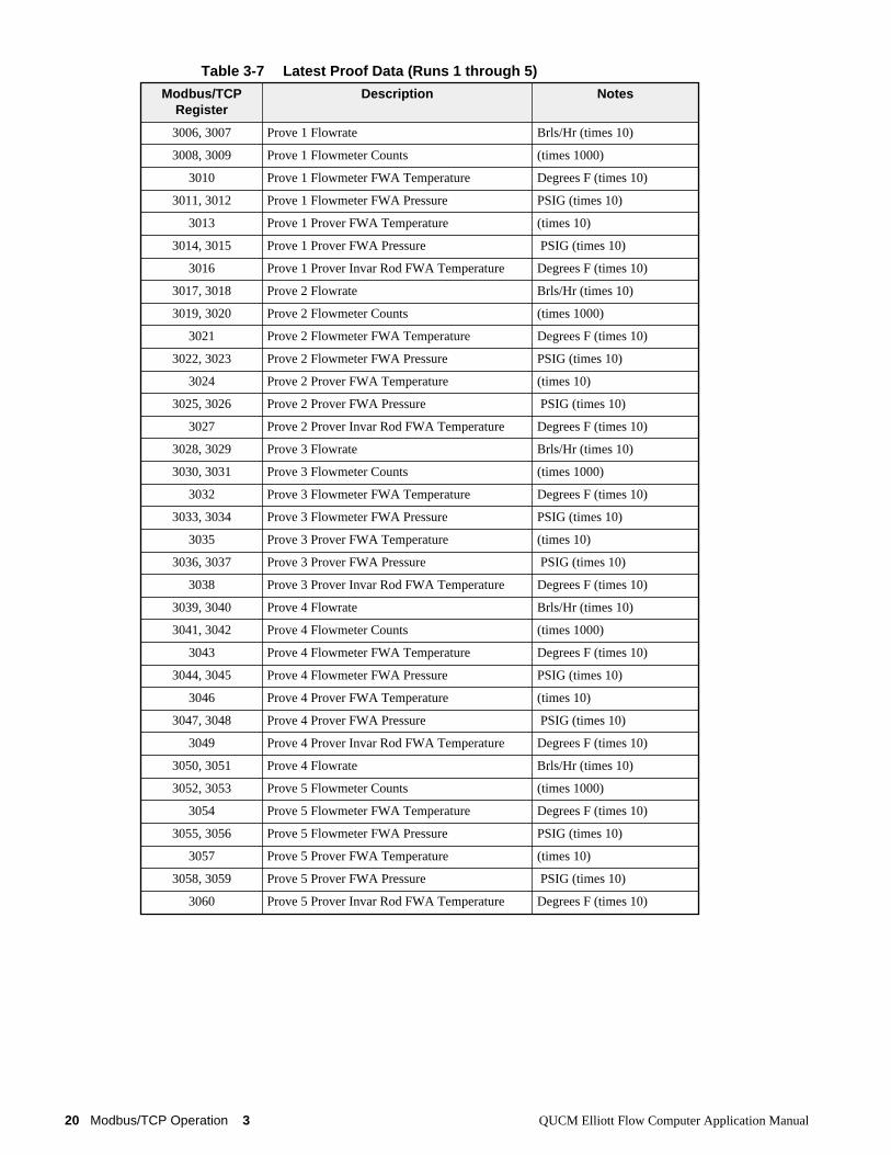
Table 3-7 Latest Proof Data (Runs 1 through 5)
Modbus/TCPRegister
Description Notes
3006, 3007 Prove 1 Flowrate Brls/Hr (times 10)
3008, 3009 Prove 1 Flowmeter Counts (times 1000)
3010 Prove 1 Flowmeter FWA Temperature Degrees F (times 10)
3011, 3012 Prove 1 Flowmeter FWA Pressure PSIG (times 10)
3013 Prove 1 Prover FWA Temperature (times 10)
3014, 3015 Prove 1 Prover FWA Pressure PSIG (times 10)
3016 Prove 1 Prover Invar Rod FWA Temperature Degrees F (times 10)
3017, 3018 Prove 2 Flowrate Brls/Hr (times 10)
3019, 3020 Prove 2 Flowmeter Counts (times 1000)
3021 Prove 2 Flowmeter FWA Temperature Degrees F (times 10)
3022, 3023 Prove 2 Flowmeter FWA Pressure PSIG (times 10)
3024 Prove 2 Prover FWA Temperature (times 10)
3025, 3026 Prove 2 Prover FWA Pressure PSIG (times 10)
3027 Prove 2 Prover Invar Rod FWA Temperature Degrees F (times 10)
3028, 3029 Prove 3 Flowrate Brls/Hr (times 10)
3030, 3031 Prove 3 Flowmeter Counts (times 1000)
3032 Prove 3 Flowmeter FWA Temperature Degrees F (times 10)
3033, 3034 Prove 3 Flowmeter FWA Pressure PSIG (times 10)
3035 Prove 3 Prover FWA Temperature (times 10)
3036, 3037 Prove 3 Prover FWA Pressure PSIG (times 10)
3038 Prove 3 Prover Invar Rod FWA Temperature Degrees F (times 10)
3039, 3040 Prove 4 Flowrate Brls/Hr (times 10)
3041, 3042 Prove 4 Flowmeter Counts (times 1000)
3043 Prove 4 Flowmeter FWA Temperature Degrees F (times 10)
3044, 3045 Prove 4 Flowmeter FWA Pressure PSIG (times 10)
3046 Prove 4 Prover FWA Temperature (times 10)
3047, 3048 Prove 4 Prover FWA Pressure PSIG (times 10)
3049 Prove 4 Prover Invar Rod FWA Temperature Degrees F (times 10)
3050, 3051 Prove 4 Flowrate Brls/Hr (times 10)
3052, 3053 Prove 5 Flowmeter Counts (times 1000)
3054 Prove 5 Flowmeter FWA Temperature Degrees F (times 10)
3055, 3056 Prove 5 Flowmeter FWA Pressure PSIG (times 10)
3057 Prove 5 Prover FWA Temperature (times 10)
3058, 3059 Prove 5 Prover FWA Pressure PSIG (times 10)
3060 Prove 5 Prover Invar Rod FWA Temperature Degrees F (times 10)
QUCM Elliott Flow Computer Application Manual 3 Modbus/TCP Operation 21
Clock Set
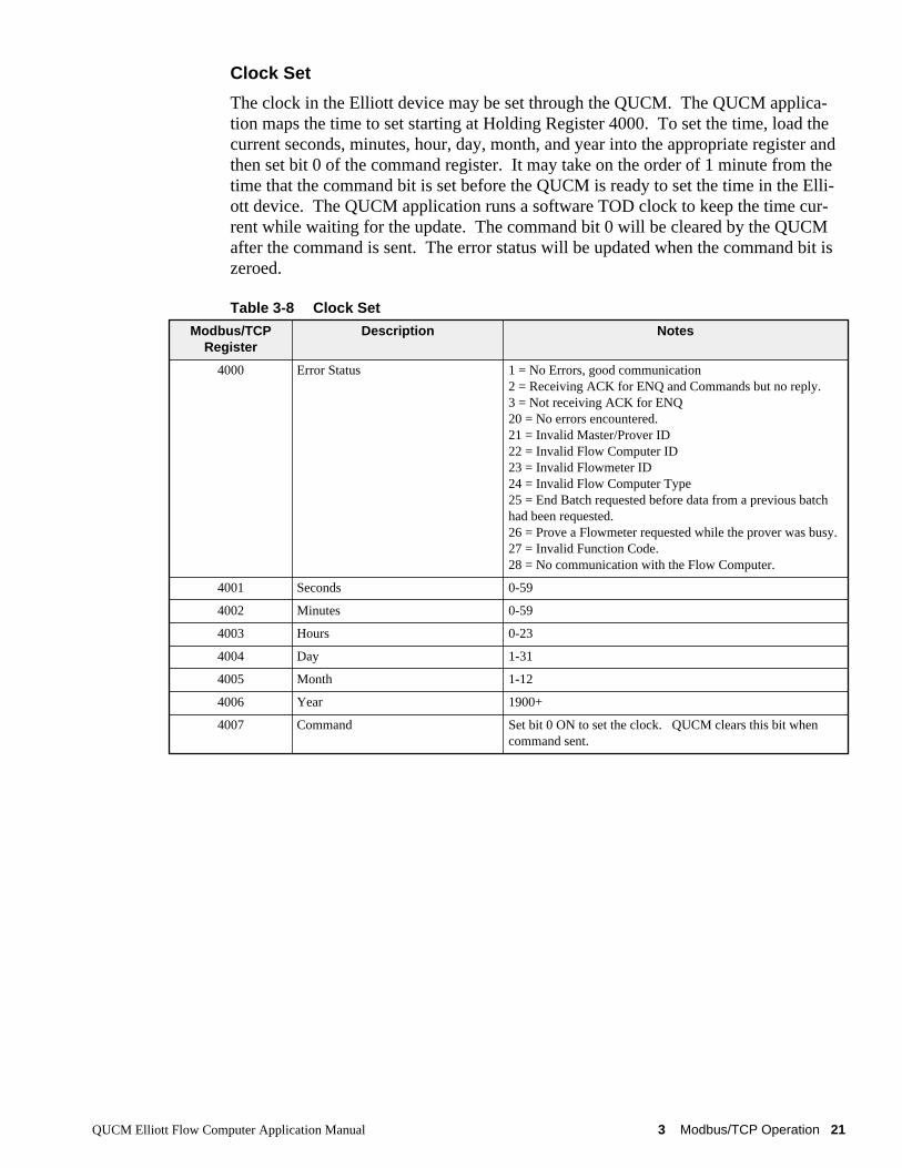
The clock in the Elliott device may be set through the QUCM. The QUCM applica-tion maps the time to set starting at Holding Register 4000. To set the time, load thecurrent seconds, minutes, hour, day, month, and year into the appropriate register andthen set bit 0 of the command register. It may take on the order of 1 minute from thetime that the command bit is set before the QUCM is ready to set the time in the Elli-ott device. The QUCM application runs a software TOD clock to keep the time cur-rent while waiting for the update. The command bit 0 will be cleared by the QUCMafter the command is sent. The error status will be updated when the command bit iszeroed.
Table 3-8 Clock Set
Modbus/TCPRegister
Description Notes
4000 Error Status 1 = No Errors, good communication2 = Receiving ACK for ENQ and Commands but no reply.3 = Not receiving ACK for ENQ20 = No errors encountered.21 = Invalid Master/Prover ID22 = Invalid Flow Computer ID23 = Invalid Flowmeter ID24 = Invalid Flow Computer Type25 = End Batch requested before data from a previous batchhad been requested.26 = Prove a Flowmeter requested while the prover was busy.27 = Invalid Function Code.28 = No communication with the Flow Computer.
4001 Seconds 0-59
4002 Minutes 0-59
4003 Hours 0-23
4004 Day 1-31
4005 Month 1-12
4006 Year 1900+
4007 Command Set bit 0 ON to set the clock. QUCM clears this bit whencommand sent.
22 Modbus/TCP Operation 3 QUCM Elliott Flow Computer Application Manual
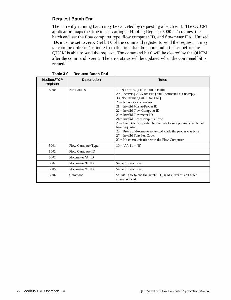
Request Batch End
The currently running batch may be canceled by requesting a batch end. The QUCMapplication maps the time to set starting at Holding Register 5000. To request thebatch end, set the flow computer type, flow computer ID, and flowmeter IDs. UnusedIDs must be set to zero. Set bit 0 of the command register to send the request. It maytake on the order of 1 minute from the time that the command bit is set before theQUCM is able to send the request. The command bit 0 will be cleared by the QUCMafter the command is sent. The error status will be updated when the command bit iszeroed.
Table 3-9 Request Batch End
Modbus/TCPRegister
Description Notes
5000 Error Status 1 = No Errors, good communication2 = Receiving ACK for ENQ and Commands but no reply.3 = Not receiving ACK for ENQ20 = No errors encountered.21 = Invalid Master/Prover ID22 = Invalid Flow Computer ID23 = Invalid Flowmeter ID24 = Invalid Flow Computer Type25 = End Batch requested before data from a previous batch hadbeen requested.26 = Prove a Flowmeter requested while the prover was busy.27 = Invalid Function Code.28 = No communication with the Flow Computer.
5001 Flow Computer Type 10 = ’A’, 11 = ’B’
5002 Flow Computer ID
5003 Flowmeter ’A’ ID
5004 Flowmeter ’B’ ID Set to 0 if not used.
5005 Flowmeter ’C’ ID Set to 0 if not used.
5006 Command Set bit 0 ON to end the batch. QUCM clears this bit whencommand sent.
QUCM Elliott Flow Computer Application Manual 3 Modbus/TCP Operation 23
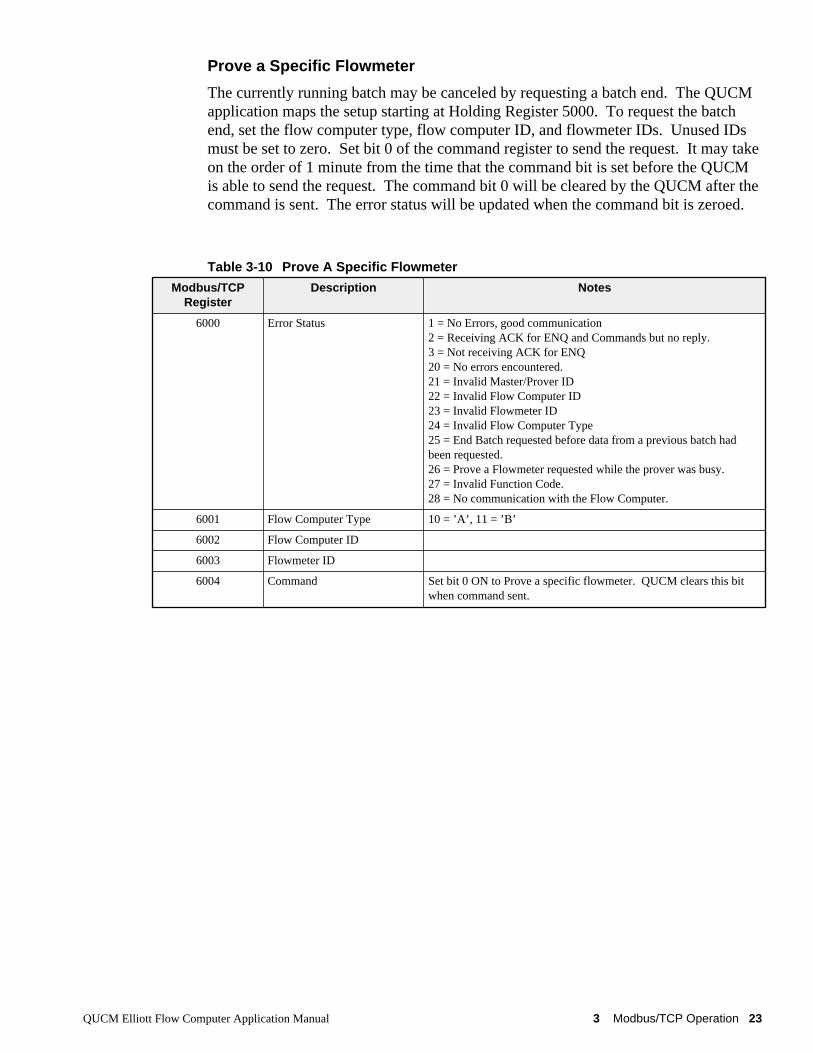
Prove a Specific Flowmeter
The currently running batch may be canceled by requesting a batch end. The QUCMapplication maps the setup starting at Holding Register 5000. To request the batchend, set the flow computer type, flow computer ID, and flowmeter IDs. Unused IDsmust be set to zero. Set bit 0 of the command register to send the request. It may takeon the order of 1 minute from the time that the command bit is set before the QUCMis able to send the request. The command bit 0 will be cleared by the QUCM after thecommand is sent. The error status will be updated when the command bit is zeroed.
Table 3-10 Prove A Specific Flowmeter
Modbus/TCPRegister
Description Notes
6000 Error Status 1 = No Errors, good communication2 = Receiving ACK for ENQ and Commands but no reply.3 = Not receiving ACK for ENQ20 = No errors encountered.21 = Invalid Master/Prover ID22 = Invalid Flow Computer ID23 = Invalid Flowmeter ID24 = Invalid Flow Computer Type25 = End Batch requested before data from a previous batch hadbeen requested.26 = Prove a Flowmeter requested while the prover was busy.27 = Invalid Function Code.28 = No communication with the Flow Computer.
6001 Flow Computer Type 10 = ’A’, 11 = ’B’
6002 Flow Computer ID
6003 Flowmeter ID
6004 Command Set bit 0 ON to Prove a specific flowmeter. QUCM clears this bitwhen command sent.
24 Modbus/TCP Operation 3 QUCM Elliott Flow Computer Application Manual
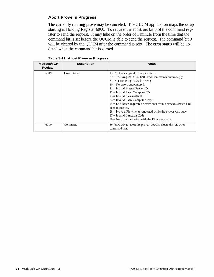
Abort Prove in Progress
The currently running prove may be canceled. The QUCM application maps the setupstarting at Holding Register 6000. To request the abort, set bit 0 of the command reg-ister to send the request. It may take on the order of 1 minute from the time that thecommand bit is set before the QUCM is able to send the request. The command bit 0will be cleared by the QUCM after the command is sent. The error status will be up-dated when the command bit is zeroed.
Table 3-11 Abort Prove in Progress
Modbus/TCPRegister
Description Notes
6009 Error Status 1 = No Errors, good communication2 = Receiving ACK for ENQ and Commands but no reply.3 = Not receiving ACK for ENQ20 = No errors encountered.21 = Invalid Master/Prover ID22 = Invalid Flow Computer ID23 = Invalid Flowmeter ID24 = Invalid Flow Computer Type25 = End Batch requested before data from a previous batch hadbeen requested.26 = Prove a Flowmeter requested while the prover was busy.27 = Invalid Function Code.28 = No communication with the Flow Computer.
6010 Command Set bit 0 ON to abort the prove. QUCM clears this bit whencommand sent.
QUCM Elliott Flow Computer Application Manual 3 Modbus/TCP Operation 25
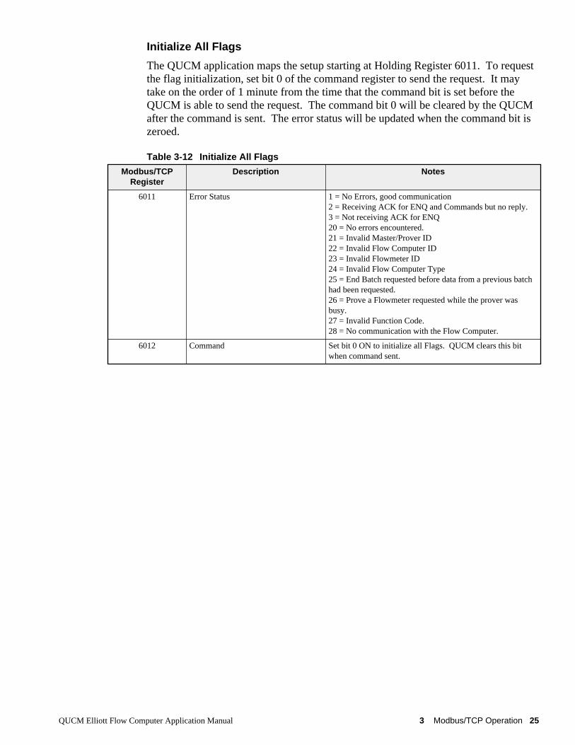
Initialize All Flags
The QUCM application maps the setup starting at Holding Register 6011. To requestthe flag initialization, set bit 0 of the command register to send the request. It maytake on the order of 1 minute from the time that the command bit is set before theQUCM is able to send the request. The command bit 0 will be cleared by the QUCMafter the command is sent. The error status will be updated when the command bit iszeroed.
Table 3-12 Initialize All Flags
Modbus/TCPRegister
Description Notes
6011 Error Status 1 = No Errors, good communication2 = Receiving ACK for ENQ and Commands but no reply.3 = Not receiving ACK for ENQ20 = No errors encountered.21 = Invalid Master/Prover ID22 = Invalid Flow Computer ID23 = Invalid Flowmeter ID24 = Invalid Flow Computer Type25 = End Batch requested before data from a previous batchhad been requested.26 = Prove a Flowmeter requested while the prover wasbusy.27 = Invalid Function Code.28 = No communication with the Flow Computer.
6012 Command Set bit 0 ON to initialize all Flags. QUCM clears this bitwhen command sent.
26 Modbus/TCP Operation 3 QUCM Elliott Flow Computer Application Manual
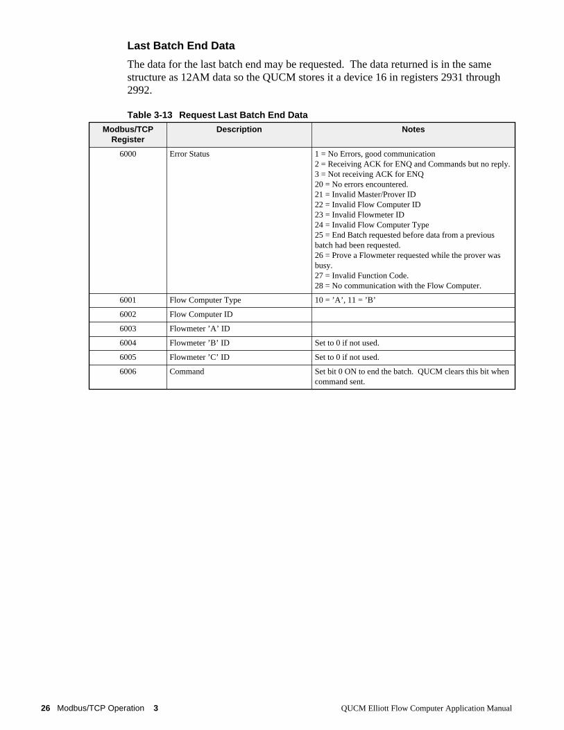
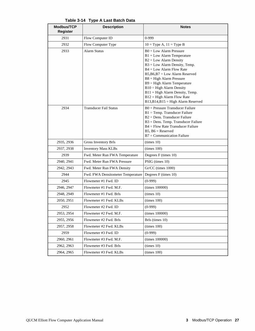
Last Batch End Data
The data for the last batch end may be requested. The data returned is in the samestructure as 12AM data so the QUCM stores it a device 16 in registers 2931 through2992.
Table 3-13 Request Last Batch End Data
Modbus/TCPRegister
Description Notes
6000 Error Status 1 = No Errors, good communication2 = Receiving ACK for ENQ and Commands but no reply.3 = Not receiving ACK for ENQ20 = No errors encountered.21 = Invalid Master/Prover ID22 = Invalid Flow Computer ID23 = Invalid Flowmeter ID24 = Invalid Flow Computer Type25 = End Batch requested before data from a previousbatch had been requested.26 = Prove a Flowmeter requested while the prover wasbusy.27 = Invalid Function Code.28 = No communication with the Flow Computer.
6001 Flow Computer Type 10 = ’A’, 11 = ’B’
6002 Flow Computer ID
6003 Flowmeter ’A’ ID
6004 Flowmeter ’B’ ID Set to 0 if not used.
6005 Flowmeter ’C’ ID Set to 0 if not used.
6006 Command Set bit 0 ON to end the batch. QUCM clears this bit whencommand sent.
QUCM Elliott Flow Computer Application Manual 3 Modbus/TCP Operation 27
Table 3-14 Type A Last Batch Data
Modbus/TCPRegister
Description Notes
2931 Flow Computer ID 0-999
2932 Flow Computer Type 10 = Type A, 11 = Type B
2933 Alarm Status B0 = Low Alarm PressureB1 = Low Alarm TemperatureB2 = Low Alarm DensityB3 = Low Alarm Density, Temp.B4 = Low Alarm Flow RateB5,B6,B7 = Low Alarm ReservedB8 = High Alarm PressureB9 = High Alarm TemperatureB10 = High Alarm DensityB11 = High Alarm Density, Temp.B12 = High Alarm Flow RateB13,B14,B15 = High Alarm Reserved
2934 Transducer Fail Status B0 = Pressure Transducer FailureB1 = Temp. Transducer FailureB2 = Dens. Transducer FailureB3 = Dens. Temp. Transducer FailureB4 = Flow Rate Transducer FailureB5, B6 = ReservedB7 = Communication Failure
2935, 2936 Gross Inventory Brls (times 10)
2937, 2938 Inventory Mass KLBs (times 100)
2939 Fwd. Meter Run FWA Temperature Degrees F (times 10)
2940, 2941 Fwd. Meter Run FWA Pressure PSIG (times 10)
2942, 2943 Fwd. Meter Run FWA Density Gr/CC (times 1000)
2944 Fwd. FWA Densitometer Temperature Degrees F (times 10)
2945 Flowmeter #1 Fwd. ID (0-999)
2946, 2947 Flowmeter #1 Fwd. M.F. (times 100000)
2948, 2949 Flowmeter #1 Fwd. Brls (times 10)
2050, 2951 Flowmeter #1 Fwd. KLBs (times 100)
2952 Flowmeter #2 Fwd. ID (0-999)
2953, 2954 Flowmeter #2 Fwd. M.F. (times 100000)
2955, 2956 Flowmeter #2 Fwd. Brls Brls (times 10)
2957, 2958 Flowmeter #2 Fwd. KLBs (times 100)
2959 Flowmeter #3 Fwd. ID (0-999)
2960, 2961 Flowmeter #3 Fwd. M.F. (times 100000)
2962, 2963 Flowmeter #3 Fwd. Brls (times 10)
2964, 2965 Flowmeter #3 Fwd. KLBs (times 100)
28 Modbus/TCP Operation 3 QUCM Elliott Flow Computer Application Manual
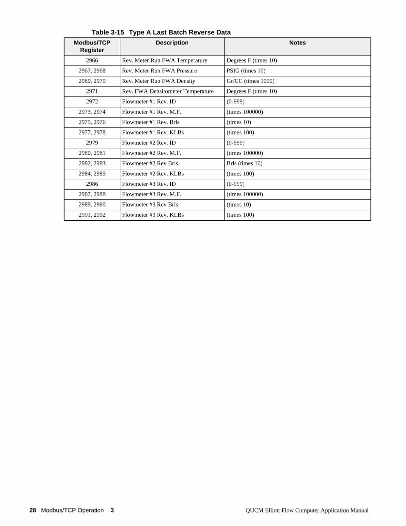
Table 3-15 Type A Last Batch Reverse Data
Modbus/TCPRegister
Description Notes
2966 Rev. Meter Run FWA Temperature Degrees F (times 10)
2967, 2968 Rev. Meter Run FWA Pressure PSIG (times 10)
2969, 2970 Rev. Meter Run FWA Density Gr/CC (times 1000)
2971 Rev. FWA Densitometer Temperature Degrees F (times 10)
2972 Flowmeter #1 Rev. ID (0-999)
2973, 2974 Flowmeter #1 Rev. M.F. (times 100000)
2975, 2976 Flowmeter #1 Rev. Brls (times 10)
2977, 2978 Flowmeter #1 Rev. KLBs (times 100)
2979 Flowmeter #2 Rev. ID (0-999)
2980, 2981 Flowmeter #2 Rev. M.F. (times 100000)
2982, 2983 Flowmeter #2 Rev Brls Brls (times 10)
2984, 2985 Flowmeter #2 Rev. KLBs (times 100)
2986 Flowmeter #3 Rev. ID (0-999)
2987, 2988 Flowmeter #3 Rev. M.F. (times 100000)
2989, 2990 Flowmeter #3 Rev Brls (times 10)
2991, 2992 Flowmeter #3 Rev. KLBs (times 100)
QUCM Elliott Flow Computer Application Manual 3 Modbus/TCP Operation 29
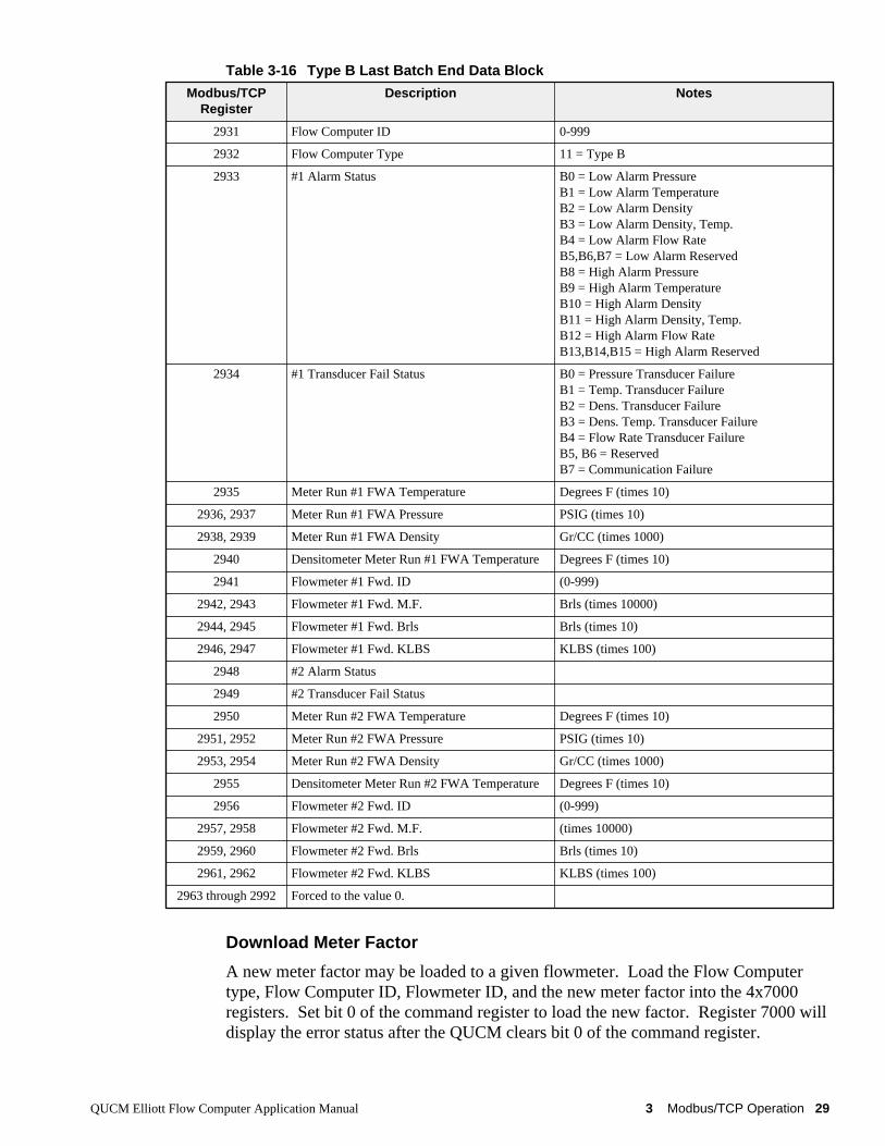
Table 3-16 Type B Last Batch End Data Block
Download Meter Factor
A new meter factor may be loaded to a given flowmeter. Load the Flow Computertype, Flow Computer ID, Flowmeter ID, and the new meter factor into the 4x7000registers. Set bit 0 of the command register to load the new factor. Register 7000 willdisplay the error status after the QUCM clears bit 0 of the command register.
Modbus/TCPRegister
Description Notes
2931 Flow Computer ID 0-999
2932 Flow Computer Type 11 = Type B
2933 #1 Alarm Status B0 = Low Alarm PressureB1 = Low Alarm TemperatureB2 = Low Alarm DensityB3 = Low Alarm Density, Temp.B4 = Low Alarm Flow RateB5,B6,B7 = Low Alarm ReservedB8 = High Alarm PressureB9 = High Alarm TemperatureB10 = High Alarm DensityB11 = High Alarm Density, Temp.B12 = High Alarm Flow RateB13,B14,B15 = High Alarm Reserved
2934 #1 Transducer Fail Status B0 = Pressure Transducer FailureB1 = Temp. Transducer FailureB2 = Dens. Transducer FailureB3 = Dens. Temp. Transducer FailureB4 = Flow Rate Transducer FailureB5, B6 = ReservedB7 = Communication Failure
2935 Meter Run #1 FWA Temperature Degrees F (times 10)
2936, 2937 Meter Run #1 FWA Pressure PSIG (times 10)
2938, 2939 Meter Run #1 FWA Density Gr/CC (times 1000)
2940 Densitometer Meter Run #1 FWA Temperature Degrees F (times 10)
2941 Flowmeter #1 Fwd. ID (0-999)
2942, 2943 Flowmeter #1 Fwd. M.F. Brls (times 10000)
2944, 2945 Flowmeter #1 Fwd. Brls Brls (times 10)
2946, 2947 Flowmeter #1 Fwd. KLBS KLBS (times 100)
2948 #2 Alarm Status
2949 #2 Transducer Fail Status
2950 Meter Run #2 FWA Temperature Degrees F (times 10)
2951, 2952 Meter Run #2 FWA Pressure PSIG (times 10)
2953, 2954 Meter Run #2 FWA Density Gr/CC (times 1000)
2955 Densitometer Meter Run #2 FWA Temperature Degrees F (times 10)
2956 Flowmeter #2 Fwd. ID (0-999)
2957, 2958 Flowmeter #2 Fwd. M.F. (times 10000)
2959, 2960 Flowmeter #2 Fwd. Brls Brls (times 10)
2961, 2962 Flowmeter #2 Fwd. KLBS KLBS (times 100)
2963 through 2992 Forced to the value 0.
30 Modbus/TCP Operation 3 QUCM Elliott Flow Computer Application Manual
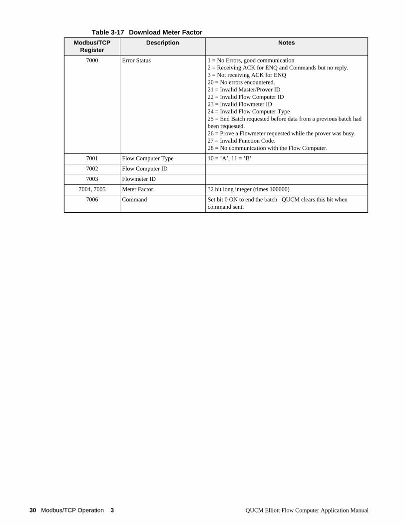
Table 3-17 Download Meter Factor
Modbus/TCPRegister
Description Notes
7000 Error Status 1 = No Errors, good communication2 = Receiving ACK for ENQ and Commands but no reply.3 = Not receiving ACK for ENQ20 = No errors encountered.21 = Invalid Master/Prover ID22 = Invalid Flow Computer ID23 = Invalid Flowmeter ID24 = Invalid Flow Computer Type25 = End Batch requested before data from a previous batch hadbeen requested.26 = Prove a Flowmeter requested while the prover was busy.27 = Invalid Function Code.28 = No communication with the Flow Computer.
7001 Flow Computer Type 10 = ’A’, 11 = ’B’
7002 Flow Computer ID
7003 Flowmeter ID
7004, 7005 Meter Factor 32 bit long integer (times 100000)
7006 Command Set bit 0 ON to end the batch. QUCM clears this bit whencommand sent.

QUCM Elliott Flow Computer Application Manual 4 Web Server 31
4
Web Server
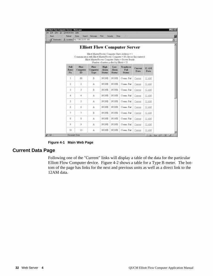
Main PageThe Main page displays a summary of the configured flowmeter devices. The tablewill display the poll entry, Flow computer ID, Flow Computer Type, High AlarmStatus, Low Alarm Status, Transducer Fail Status, links to the Current Data and 12AMdata.
Figure 4-1 shows an example page with the Elliott polling 15 devices.
At the bottom of the Main page are links to the Latest Prove data, Control for the Elli-ott, Statistics on this QUCM, and a page for configuring this QUCM.
32 Web Server 4 QUCM Elliott Flow Computer Application Manual
Figure 4-1 Main Web Page
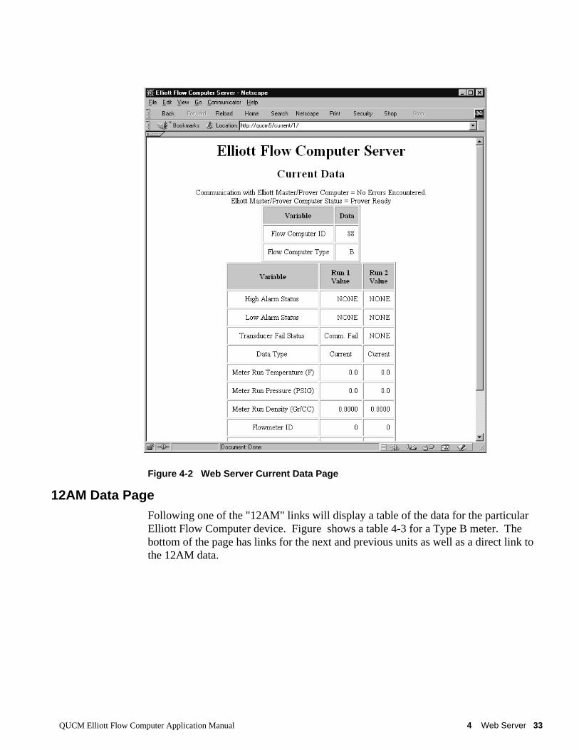
Current Data PageFollowing one of the "Current" links will display a table of the data for the particularElliott Flow Computer device. Figure 4-2 shows a table for a Type B meter. The bot-tom of the page has links for the next and previous units as well as a direct link to the12AM data.
QUCM Elliott Flow Computer Application Manual 4 Web Server 33
Figure 4-2 Web Server Current Data Page
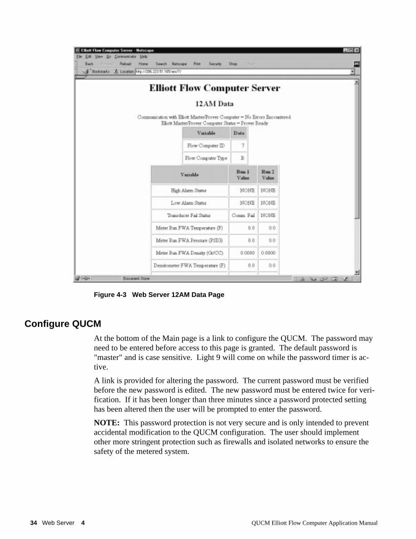
12AM Data PageFollowing one of the "12AM" links will display a table of the data for the particularElliott Flow Computer device. Figure shows a table 4-3 for a Type B meter. Thebottom of the page has links for the next and previous units as well as a direct link tothe 12AM data.
34 Web Server 4 QUCM Elliott Flow Computer Application Manual
Figure 4-3 Web Server 12AM Data Page
Configure QUCMAt the bottom of the Main page is a link to configure the QUCM. The password mayneed to be entered before access to this page is granted. The default password is"master" and is case sensitive. Light 9 will come on while the password timer is ac-tive.
A link is provided for altering the password. The current password must be verifiedbefore the new password is edited. The new password must be entered twice for veri-fication. If it has been longer than three minutes since a password protected settinghas been altered then the user will be prompted to enter the password.
NOTE: This password protection is not very secure and is only intended to preventaccidental modification to the QUCM configuration. The user should implementother more stringent protection such as firewalls and isolated networks to ensure thesafety of the metered system.
QUCM Elliott Flow Computer Application Manual 4 Web Server 35
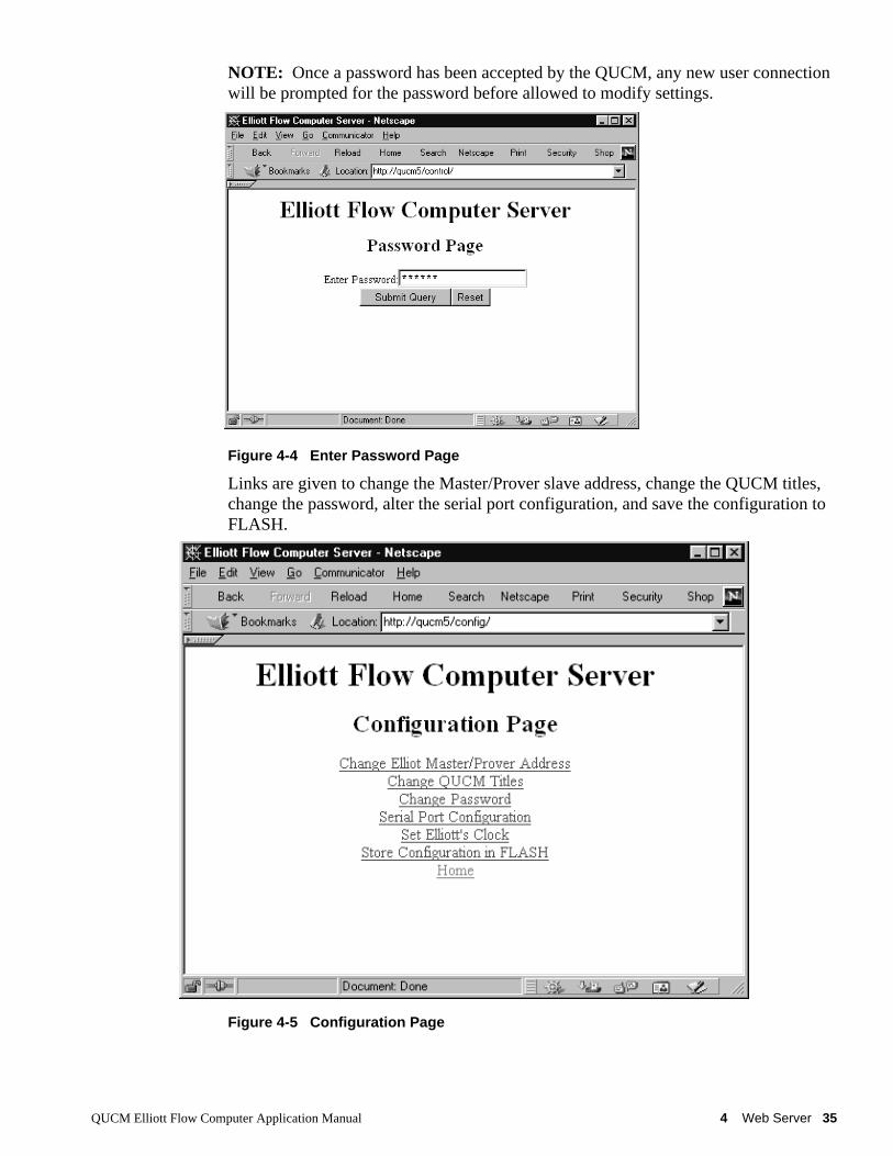
NOTE: Once a password has been accepted by the QUCM, any new user connectionwill be prompted for the password before allowed to modify settings.
Figure 4-4 Enter Password Page
Links are given to change the Master/Prover slave address, change the QUCM titles,change the password, alter the serial port configuration, and save the configuration toFLASH.
Figure 4-5 Configuration Page
36 Web Server 4 QUCM Elliott Flow Computer Application Manual
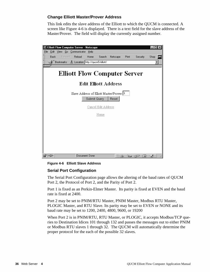
Change Elliott Master/Prover Address
This link edits the slave address of the Elliott to which the QUCM is connected. Ascreen like Figure 4-6 is displayed. There is a text field for the slave address of theMaster/Prover. The field will display the currently assigned number.
Figure 4-6 Elliott Slave Address
Serial Port Configuration
The Serial Port Configuration page allows the altering of the baud rates of QUCMPort 2, the Protocol of Port 2, and the Parity of Port 2.
Port 1 is fixed as an Perkin-Elmer Master. Its parity is fixed at EVEN and the baudrate is fixed at 2400.
Port 2 may be set to PNIM/RTU Master, PNIM Master, Modbus RTU Master,PLOGIC Master, and RTU Slave. Its parity may be set to EVEN or NONE and itsbaud rate may be set to 1200, 2400, 4800, 9600, or 19200
When Port 2 is in PNIM/RTU, RTU Master, or PLOGIC, it accepts Modbus/TCP que-ries to Destination Idices 101 through 132 and passes the messages out to either PNIMor Modbus RTU slaves 1 through 32. The QUCM will automatically determine theproper protocol for the each of the possible 32 slaves.
QUCM Elliott Flow Computer Application Manual 4 Web Server 37
Figure 4-7 Serial Port Page
Save Settings to FLASH
After completion of the configuration, be sure to save the settings to flash. Otherwisethe modifications will be lost on the next power cycle of the QUCM. Once the set-tings are saved to flash, the QUCM’s configuration, including its IP settings, will besafe indefinitely.
Elliott ControlThe link at the bottom of the main page for Elliott Control allows complete control ofall the Flow Computer functions from the Web interface. The user may set the Elliottclock, request a batch end, prove a specific flowmeter, abort a prove in progress, in-itialize all flags, download a new meter factor, request and view last batch end data fora specific flowmeter.
A password is required before entering any of these pages. The password is the sameas the configuration password.
38 Web Server 4 QUCM Elliott Flow Computer Application Manual
Figure 4-8 Elliott Control Page
Statistics PageAt the bottom of the Main page is a link to some statistical information about thisQUCM. (See Figure 4-9)
QUCM Elliott Flow Computer Application Manual 4 Web Server 39
Figure 4-9 Statistics Web Page
![ROBERT JAMES ELLIOTT CURRICULUM VITAE CITIZENSHIP ...haskayne.ucalgary.ca/.../robert-elliott-cv.pdf · R.J. Elliott – CV [September, 2006 - Page 1] ROBERT JAMES ELLIOTT CURRICULUM](https://img.pdfslide.net/doc/110x75/5fdc51cfa239fb15507e657b/robert-james-elliott-curriculum-vitae-citizenship-rj-elliott-a-cv-september.jpg)