Embed Size (px)
Citation preview
1
Application GuideEurope, Middle East,
and Africa
QuickNet™ Applications in the Data CentreQuickNet can be used for a wide variety of permanent link trunks and equipment cord harnesses that are common in data centre architectures such as Middle of Row or End of Row configurations.
QuickNet™ Copper Cabling SystemsWith the benefits of quick network deployment, assured performance, quality, and easy redeployment, the Panduit™ QuickNet™ Copper Cabling System is the perfect infrastructure solution for today’s data centres.
Available in a range of configurations from standard to fully custom, these factory terminated cable assemblies meet the unique needs of data centre projects of any scale.
This guide covers common considerations for using QuickNet Copper systems:
• Applications in the data centre• QuickNet termination options & common configurations• Specifying options, measuring for lengths and selecting QuickNet part numbers
QuickNet™ Copper Cabling in the Data Centre
Quick Reference
Common QuickNet Configurations ............ 2
How to Use QuickNet ..................... 3
How to Configure QuickNet ..................... 8
Guide for MeasuringQuickNet Lengths ..... 11
QuickNet StandardPart Numbers ........... 13
QuickNet ConfiguredPart Numbers ........... 14
QuickNet AccessoryPart Numbers ........... 15
Overhead In-Row Trunks
Switch Port Harness
Under-floor In-Row Trunks
Under-floor Row-to-Row / Pod-to-Pod Trunks
Overhead Row-to-Row / Pod-to-Pod Trunks
QuickNet Application Guide Europe, Middle East, and Africa
2
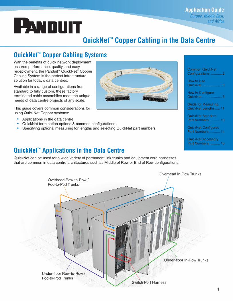
Cassette to Cassette• Cassette of six jack modules on both ends of assembly• Typically used in cabinet-to-cabinet permanent link trunks• Installs into QuickNet™ Patch Panels on both ends in common interconnect and
cross connect architectures, with cassette enabling quick installation into panels• The most common QuickNet configuration for permanent link trunks
• QuickNet Standard Parts for EMEA: UTP or STP, Cassette-Cassette, white cable, black jack modules (See p. 13 for more information on standard part numbers)
QuickNet™ Cable Assembly Components
Common QuickNet™ Cable Assembly Configurations
Jack to Jack• Six loose jack modules on both ends of assembly• Typically used in cabinet-to-cabinet permanent link trunks• Installs into Mini-Com™ Modular Patch Panels (or QuickNet™ Patch Panels with panel
adapters) on both ends in common interconnect and cross connect architectures• Compatible with PViQ™ and PanView™ intelligent modular patching systems
Cassette to Plug Pack / Cassette to Plug• Similar configuration as above, but with plug pack of six modular plugs on one end
or six loose modular plugs• Typically used for in-cabinet or cabinet-to-cabinet equipment cord harnesses• Installs into QuickNet™ Patch Panels on one end and switch ports on the other for
switch port replication applications• Plug pack enables quick installation & removal of modular plugs into switch ports
Jack to Plug Pack• Similar configuration as above, but with plug pack of six modular plugs on one end• Typically used for in-cabinet or cabinet-to-cabinet equipment cord harnesses• Installs into Mini-Com™ Modular Patch Panels on one end and switch ports on the
other for switch port replication applications• Plug pack enables quick installation & removal of modular plugs into switch ports
CableFactory-bundled trunk of six cables.
Cable types: • UTP - Cat 6, Cat 6A,
Cat 6A SD (Small Diameter)• STP - Cat 6A (S/FTP & U/FTP)
End 2End 1
Shielded CassetteUTP Cassette UTP Jack Modules UTP Modular Plugs Unterminated 6-Port Plug Pack
End 1 & End 2 Options End 2 only Options
QuickNet Application Guide Europe, Middle East, and Africa
3
How to Use QuickNet™ Cable AssembliesThe following sections illustrate and describe in greater detail how QuickNet trunks and harnesses are used in common data centre cabling configurations.
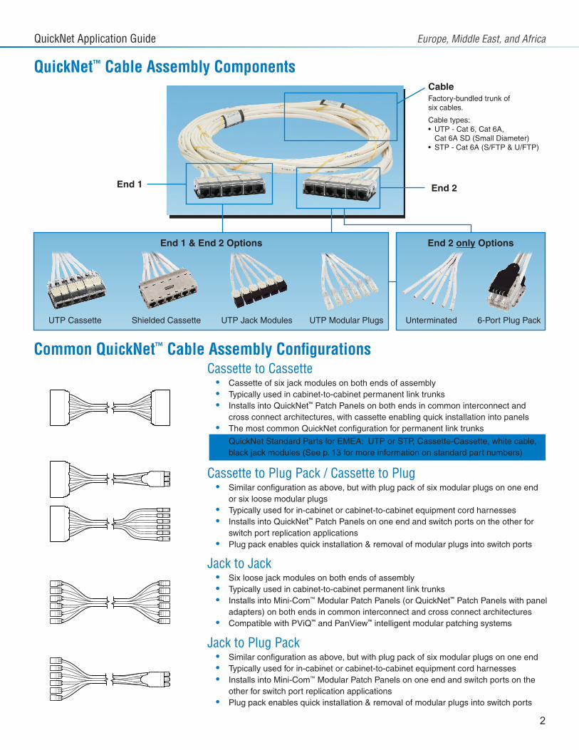
Two-Connector InterconnectIn this very common data centre cabling configuration, a permanent link trunk runs between patch panels on each end, with patch cords used to interconnect the active equipment. Often the panel on one end is in a switch (or network) cabinet, and the panel on the other end is in a server or storage cabinet.
QuickNet™ Cassette-to-Cassette
Cable Assembly
QuickNet™ PatchPanels
Patch CordsPatch Cords
Switch / NetworkCabinet
Server or StorageCabinet
Figure 1 - Two-Connector Interconnect
Best QuickNet choice: Cassette-to-Cassette cable assembly used as the permanent link trunk, mated to QuickNet™ Patch Panels at each end.
Alternative QuickNet choice: Cassette-to-Jack or Jack-to-Jack cable assemblies used as the permanent link, mating to Mini-Com™ Modular Patch Panels as appropriate.
QuickNet Application Guide Europe, Middle East, and Africa
4
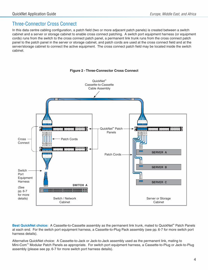
Three-Connector Cross ConnectIn this data centre cabling configuration, a patch field (two or more adjacent patch panels) is created between a switch cabinet and a server or storage cabinet to enable cross connect patching. A switch port equipment harness (or equipment cords) runs from the switch to the cross connect patch panel, a permanent link trunk runs from the cross connect patch panel to the patch panel in the server or storage cabinet, and patch cords are used at the cross connect field and at the server/storage cabinet to connect the active equipment. The cross connect patch field may be located inside the switch cabinet.
QuickNet™ PatchPanels
Patch Cords
Patch CordsCrossConnect
SwitchPortEquipmentHarness
(Seepp. 6-7for moredetails) Switch / Network
CabinetServer or Storage
Cabinet
Best QuickNet choice: A Cassette-to-Cassette assembly as the permanent link trunk, mated to QuickNet™ Patch Panels at each end. For the switch port equipment harness, a Cassette-to-Plug Pack assembly (see pp. 6-7 for more switch port harness details).
Alternative QuickNet choice: A Cassette-to-Jack or Jack-to-Jack assembly used as the permanent link, mating to Mini-Com™ Modular Patch Panels as appropriate. For switch port equipment harness, a Cassette-to-Plug or Jack-to-Plug assembly (please see pp. 6-7 for more switch port harness details).
Figure 2 - Three-Connector Cross Connect
QuickNet™ Cassette-to-Cassette
Cable Assembly
QuickNet Application Guide Europe, Middle East, and Africa
5
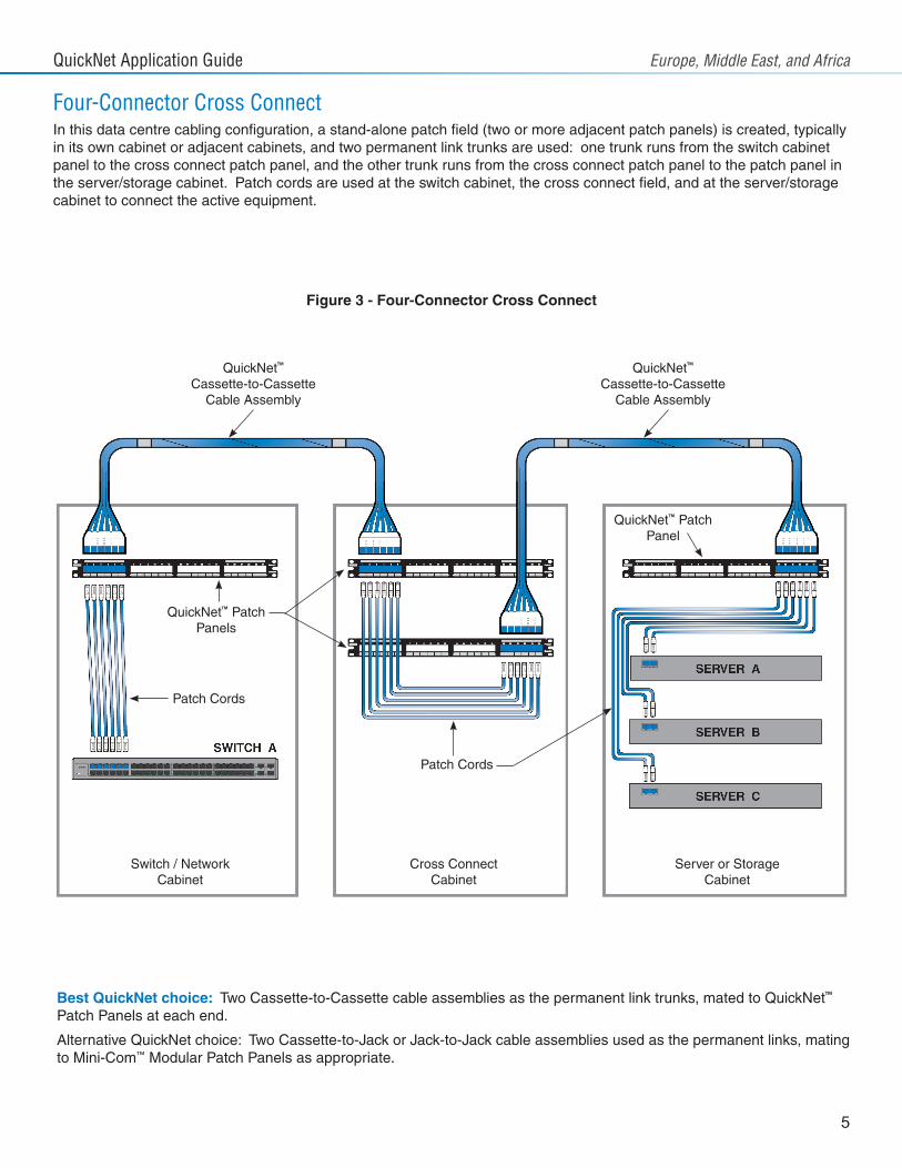
Four-Connector Cross ConnectIn this data centre cabling configuration, a stand-alone patch field (two or more adjacent patch panels) is created, typically in its own cabinet or adjacent cabinets, and two permanent link trunks are used: one trunk runs from the switch cabinet panel to the cross connect patch panel, and the other trunk runs from the cross connect patch panel to the patch panel in the server/storage cabinet. Patch cords are used at the switch cabinet, the cross connect field, and at the server/storage cabinet to connect the active equipment.
Best QuickNet choice: Two Cassette-to-Cassette cable assemblies as the permanent link trunks, mated to QuickNet™ Patch Panels at each end.
Alternative QuickNet choice: Two Cassette-to-Jack or Jack-to-Jack cable assemblies used as the permanent links, mating to Mini-Com™ Modular Patch Panels as appropriate.
QuickNet™ PatchPanels
QuickNet™ PatchPanel
Patch Cords
Patch Cords
Switch / NetworkCabinet
Cross ConnectCabinet
Server or StorageCabinet
Figure 3 - Four-Connector Cross Connect
QuickNet™ Cassette-to-Cassette
Cable Assembly
QuickNet™ Cassette-to-Cassette
Cable Assembly
QuickNet Application Guide Europe, Middle East, and Africa
6
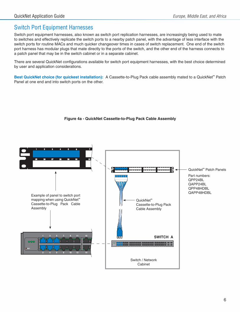
Switch Port Equipment HarnessesSwitch port equipment harnesses, also known as switch port replication harnesses, are increasingly being used to mate to switches and effectively replicate the switch ports to a nearby patch panel, with the advantage of less interface with the switch ports for routine MACs and much quicker changeover times in cases of switch replacement. One end of the switch port harness has modular plugs that mate directly to the ports of the switch, and the other end of the harness connects to a patch panel that may be in the switch cabinet or in a separate cabinet.
There are several QuickNet configurations available for switch port equipment harnesses, with the best choice determined by user and application considerations.
Best QuickNet choice (for quickest installation): A Cassette-to-Plug Pack cable assembly mated to a QuickNet™ Patch Panel at one end and into switch ports on the other.
Switch / NetworkCabinet
QuickNet™
Cassette-to-Plug PackCable Assembly
QuickNet™ Patch Panels
Part numbers:QPP24BLQAPP24BLQPP48HDBLQAPP48HDBL
Example of panel to switch port mapping when using QuickNet™ Cassette-to-Plug Pack Cable Assembly
Figure 4a - QuickNet Cassette-to-Plug Pack Cable Assembly
QuickNet Application Guide Europe, Middle East, and Africa
7
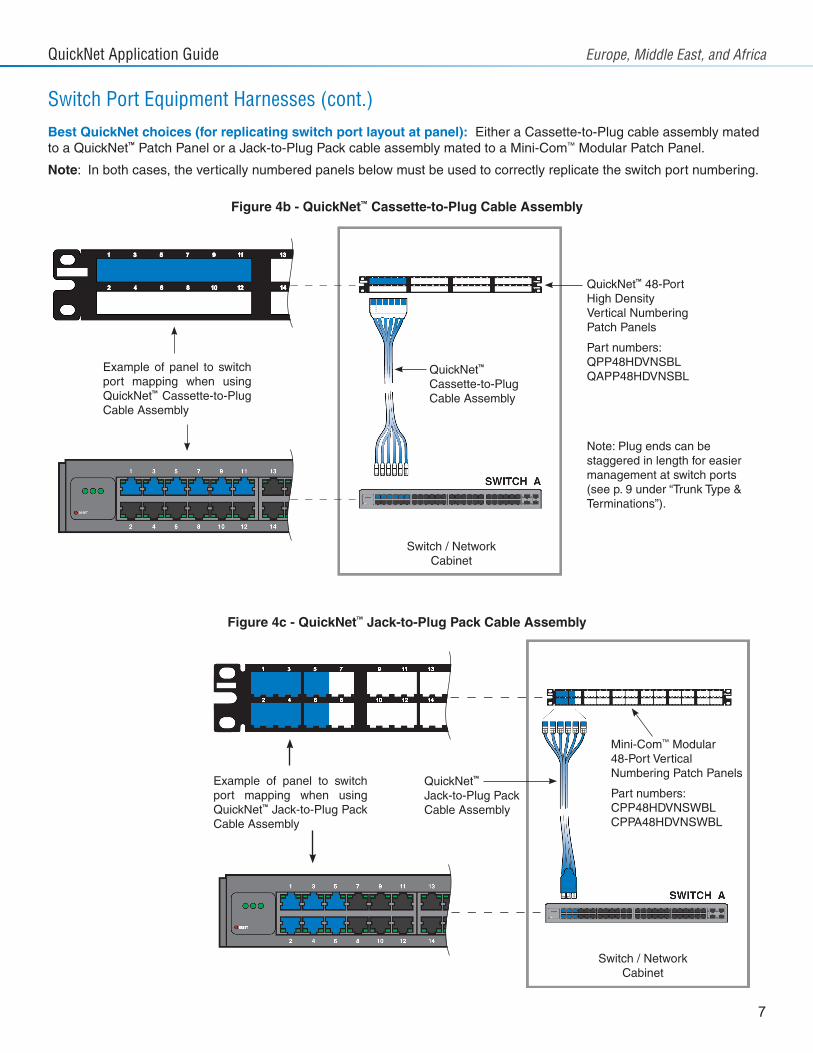
Switch Port Equipment Harnesses (cont.)
QuickNet™ 48-PortHigh DensityVertical Numbering Patch Panels
Part numbers:QPP48HDVNSBLQAPP48HDVNSBL
Note: Plug ends can be staggered in length for easier management at switch ports (see p. 9 under “Trunk Type & Terminations”).
QuickNet™
Cassette-to-PlugCable Assembly
Mini-Com™ Modular48-Port Vertical Numbering Patch Panels
Part numbers:CPP48HDVNSWBLCPPA48HDVNSWBL
QuickNet™
Jack-to-Plug PackCable Assembly
Best QuickNet choices (for replicating switch port layout at panel): Either a Cassette-to-Plug cable assembly mated to a QuickNet™ Patch Panel or a Jack-to-Plug Pack cable assembly mated to a Mini-Com™ Modular Patch Panel.
Note: In both cases, the vertically numbered panels below must be used to correctly replicate the switch port numbering.
Example of panel to switch port mapping when using QuickNet™ Cassette-to-Plug Cable Assembly
Example of panel to switch port mapping when using QuickNet™ Jack-to-Plug Pack Cable Assembly
Switch / NetworkCabinet
Switch / NetworkCabinet
Figure 4b - QuickNet™ Cassette-to-Plug Cable Assembly
Figure 4c - QuickNet™ Jack-to-Plug Pack Cable Assembly
QuickNet Application Guide Europe, Middle East, and Africa
8
The QuickNet product family has a wide range of available configuration options from standard “Cassette-to-Cassette” cable assemblies to fully custom assemblies that are user-defined in a number of areas. In this section, each of the main configuration options for QuickNet are explained and typical considerations for data centre applications are covered.
Cable Performance Level & ColourThe performance level of the cable selected in the assembly indicates the maximum data rate that the cable assembly will support and should be selected to support the active equipment speeds projected over the life of the cabling. Depending upon the performance level selected, unshielded (UTP) or shielded (STP) constructions are available. Connectivity is matched to the performance level of the cable selected.
Performance level choices are:
• UTP - Category 6, Category 6A or Category 6A SD (Small Diameter)• STP - Category 6 F/UTP, Category 6A S/FTP, Category 6A S/FTP Stranded or Category 6A U/FTP
In QuickNet™ Cable Assemblies, six channels of the selected cable are grouped together and bundled with a spiral-wrapped binder to form a factory-engineered six-cable trunk.
Category 6 cable supports Gigabit data rates, while Category 6A cables support 10 Gigabit data rates, both up to a maximum channel length of 100 metres (328 feet). Category 6A SD (Small Diameter) cable supports 10 Gigabit data rates up to a maximum channel length of 70 metres (229 feet).
UTP cabling provides the advantage of not requiring electrical bonding to the equipment and Panduit’s TX6A™ 10Gig™ UTP Copper Cable with MaTriX Technology provides 10 Gigabit performance in a UTP solution. STP cabling is often used where there are concerns about EMI/RFI noise or data security.
Cable colour choices for cable performance levels are:
• White (for all cables except Category 6 F/UTP and Category 6A S/FTP Stranded)• Dark Grey (for Category 6 F/UTP)• International Grey (for Category 6A S/FTP Stranded)
Note: Other colours may be available for given performance levels and flame ratings. Please contact Panduit customer service for assistance.
QuickNet Standard Parts: Category 6 UTP, Category 6A UTP, Category 6A SD UTP, Category 6A S/FTP, and Category 6A U/FTP performance levels are available, all with white colour cable.
Cable Flame RatingCable flame rating for all cable types is:
• Low Smoke Zero Halogen (LSZH, IEC 60332-1)
Note: “LSZH-3” (IEC 60332-3) flame rating may be available for certain cable performance levels. Please contact Panduit customer service for assistance.
QuickNet Standard Parts: LSZH (IEC 60332-1) flame rating on all cable performance levels.
How to Configure QuickNet™ Cable Assemblies
QuickNet Application Guide Europe, Middle East, and Africa
9
Assembly OptionsThe main assembly options available are:
• Pulling Eye• Braided Expandable Sleeving
A pulling eye is a loop of braided sleeve material that is applied to one end of the QuickNet assembly, over either loose jack modules or loose modular plugs, and is used to aid in laying the cable in pathways at deployment.
Note: Pulling eye cannot be used on an end that has cassette termination.
Note: Panduit recommends that all QuickNet assemblies be laid into data centre pathways during deployment; however, if pulling of the assemblies is required, care must be taken to ensure the assemblies are not pulled across sharp edges or corners which can damage the spiral binder which holds the cable bundle.
Braided expandable sleeving is available in black colour and is sleeved over the length of the assembly. The sleeving is secured to the bundle at the heat shrink located at each end of the assembly.
QuickNet Standard Parts: No assembly option is included.
Trunk Type & TerminationsBoth ends of a QuickNet™ Cable Assembly include one of a range of factory termination options – each end can be different and are selected based upon the desired application of the trunk or harness within the data centre. Colour choices are available for several of the termination types.
Termination choices are:
• Cassette with six jack modules (UTP or STP)• Six loose jack modules (UTP or STP) • Six loose modular plugs (UTP only)• Plug pack with six modular plugs (UTP, one end only)• Unterminated (one end only)
The most common QuickNet termination combinations for permanent link horizontal cable trunks are Cassette-to-Cassette or Jack-to-Jack. Cassette terminations are preferred for rapid installation and ease of later moves, adds and changes. Loose jack terminations are used when the jack modules must be separated within panels or when used with Mini-Com™ Modular Patch Panels.
For equipment cord harnesses for use in switch port replication applications, Cassette (or Jack) to loose plug (or plug pack) terminations are typically used.
Staggered configurations are available for loose jack and loose plug terminations to assist in dressing the cable trunk or harness to one side or the other.
Termination options colour choices are:
• UTP Cassette or jack modules – black, white, blue, green, red, yellow, orange, violet, electric ivory, international grey and off white.
• STP Cassettes and jack modules – all shielded cassettes are silver, and all shielded jack modules are black.• Modular plugs – all plugs are clear (no colour choice).• Plug packs – black, white, red, blue for standard plug pack. Recessed plug pack is available in silver only.
QuickNet Standard Parts: Termination on both ends is a Cassette with black jack modules (UTP or STP based on type of cable selected).
QuickNet Cable Assembly
Braided sleeving
Loose jack modules or plugs inside
Loop for pulling
Pulling Eye Option
QuickNet Application Guide Europe, Middle East, and Africa
10
Length of AssemblyLength options are:
• From 3m to 90m, in 0.5 metre increments – for all cable types, except Category 6A SD (Small Diameter) UTP cable• From 3m to 60m, in 0.5 metre increments – for Category 6A SD (Small Diameter) UTP cable
The length of a QuickNet assembly is the total distance from the terminated connector on one end to the terminated connector on the other. For staggered assemblies, the distance is measured from the longest end of the stagger.
QuickNet Standard Parts: Length options are every one metre from 3m to 30m, and 35m & 40m, for all standard QuickNet cable types.
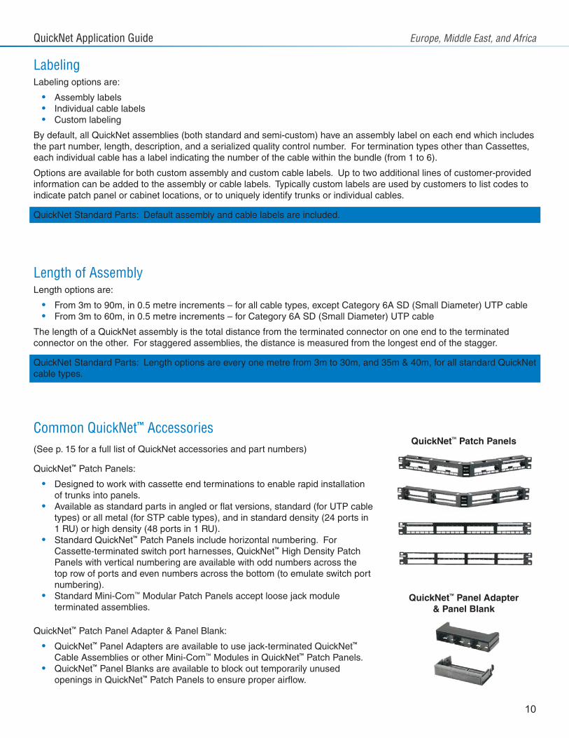
Common QuickNet™ Accessories(See p. 15 for a full list of QuickNet accessories and part numbers)
QuickNet™ Patch Panels:
• Designed to work with cassette end terminations to enable rapid installation of trunks into panels.
• Available as standard parts in angled or flat versions, standard (for UTP cable types) or all metal (for STP cable types), and in standard density (24 ports in 1 RU) or high density (48 ports in 1 RU).
• Standard QuickNet™ Patch Panels include horizontal numbering. For Cassette-terminated switch port harnesses, QuickNet™ High Density Patch Panels with vertical numbering are available with odd numbers across the top row of ports and even numbers across the bottom (to emulate switch port numbering).
• Standard Mini-Com™ Modular Patch Panels accept loose jack module terminated assemblies.
QuickNet™ Patch Panel Adapter & Panel Blank:
• QuickNet™ Panel Adapters are available to use jack-terminated QuickNet™ Cable Assemblies or other Mini-Com™ Modules in QuickNet™ Patch Panels.
• QuickNet™ Panel Blanks are available to block out temporarily unused openings in QuickNet™ Patch Panels to ensure proper airflow.
LabelingLabeling options are:
• Assembly labels• Individual cable labels• Custom labeling
By default, all QuickNet assemblies (both standard and semi-custom) have an assembly label on each end which includes the part number, length, description, and a serialized quality control number. For termination types other than Cassettes, each individual cable has a label indicating the number of the cable within the bundle (from 1 to 6).
Options are available for both custom assembly and custom cable labels. Up to two additional lines of customer-provided information can be added to the assembly or cable labels. Typically custom labels are used by customers to list codes to indicate patch panel or cabinet locations, or to uniquely identify trunks or individual cables.
QuickNet Standard Parts: Default assembly and cable labels are included.
QuickNet™ Patch Panels
QuickNet™ Panel Adapter & Panel Blank
QuickNet Application Guide Europe, Middle East, and Africa
11
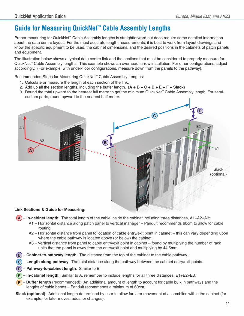
Guide for Measuring QuickNet™ Cable Assembly LengthsProper measuring for QuickNet™ Cable Assembly lengths is straightforward but does require some detailed information about the data centre layout. For the most accurate length measurements, it is best to work from layout drawings and know the specific equipment to be used, the cabinet dimensions, and the desired positions in the cabinets of patch panels and equipment.
The illustration below shows a typical data centre link and the sections that must be considered to properly measure for QuickNet™ Cable Assembly lengths. This example shows an overhead in-row installation. For other configurations, adjust accordingly. (For example, with under-floor configurations, measure down from the panels to the pathway).
Recommended Steps for Measuring QuickNet™ Cable Assembly Lengths:1. Calculate or measure the length of each section of the link.2. Add up all the section lengths, including the buffer length. (A + B + C + D + E + F + Slack)3. Round the total upward to the nearest full metre to get the minimum QuickNet™ Cable Assembly length. For semi-
custom parts, round upward to the nearest half metre.
Link Sections & Guide for Measuring:
– In-cabinet length: The total length of the cable inside the cabinet including three distances, A1+A2+A3:A1 – Horizontal distance along patch panel to vertical manager – Panduit recommends 60cm to allow for cable
routing. A2 – Horizontal distance from panel to location of cable entry/exit point in cabinet – this can vary depending upon
where the cable pathway is located above (or below) the cabinet.A3 – Vertical distance from panel to cable entry/exit point in cabinet – found by multiplying the number of rack
units that the panel is away from the entry/exit point and multiplying by 44.5mm.
– Cabinet-to-pathway length: The distance from the top of the cabinet to the cable pathway.
– Length along pathway: The total distance along the pathway between the cabinet entry/exit points.
– Pathway-to-cabinet length: Similar to B.
– In-cabinet length: Similar to A, remember to include lengths for all three distances, E1+E2+E3.
– Buffer length (recommended): An additional amount of length to account for cable bulk in pathways and the lengths of cable bends – Panduit recommends a minimum of 60cm.
Slack (optional): Additional length determined by user to allow for later movement of assemblies within the cabinet (for example, for later moves, adds, or changes).
A
B
C
D
E
F
E3E2
E1
Slack(optional)
A
A1A2
A3
B
CD
QuickNet Application Guide Europe, Middle East, and Africa
12
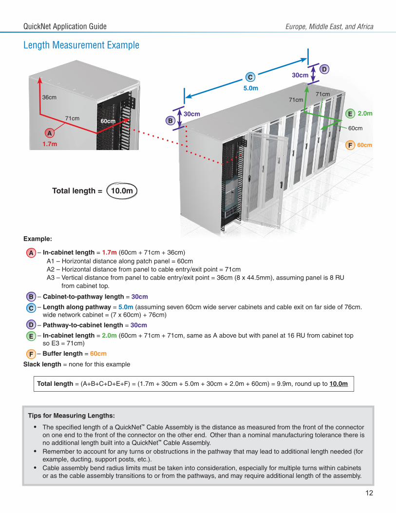
Example:
– In-cabinet length = 1.7m (60cm + 71cm + 36cm) A1 – Horizontal distance along patch panel = 60cm A2 – Horizontal distance from panel to cable entry/exit point = 71cm A3 – Vertical distance from panel to cable entry/exit point = 36cm (8 x 44.5mm), assuming panel is 8 RU from cabinet top.
– Cabinet-to-pathway length = 30cm
– Length along pathway = 5.0m (assuming seven 60cm wide server cabinets and cable exit on far side of 76cm. wide network cabinet = (7 x 60cm) + 76cm)
– Pathway-to-cabinet length = 30cm
– In-cabinet length = 2.0m (60cm + 71cm + 71cm, same as A above but with panel at 16 RU from cabinet top so E3 = 71cm)
– Buffer length = 60cm
Slack length = none for this example
Total length = (A+B+C+D+E+F) = (1.7m + 30cm + 5.0m + 30cm + 2.0m + 60cm) = 9.9m, round up to 10.0m
Length Measurement Example
A
B
C
D
E
F
A
B
CD
E
F
60cm71cm
1.7m
36cm 71cm71cm
60cm
2.0m
60cm
30cm
30cm
5.0m
Total length = 10.0m
Tips for Measuring Lengths:
• The specified length of a QuickNet™ Cable Assembly is the distance as measured from the front of the connector on one end to the front of the connector on the other end. Other than a nominal manufacturing tolerance there is no additional length built into a QuickNet™ Cable Assembly.
• Remember to account for any turns or obstructions in the pathway that may lead to additional length needed (for example, ducting, support posts, etc.).
• Cable assembly bend radius limits must be taken into consideration, especially for multiple turns within cabinets or as the cable assembly transitions to or from the pathways, and may require additional length of the assembly.
QuickNet Application Guide Europe, Middle East, and Africa
13
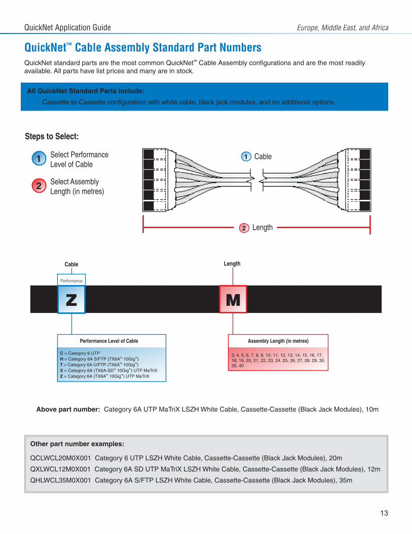
Q
QuickNet™ Cable Assembly Standard Part Numbers
L W C 1 0 0 X 10
C = Category 6 UTPH = Category 6A S/FTP (TX6A™ 10Gig™)T = Category 6A U/FTP (TX6A™ 10Gig™)X = Category 6A (TX6A-SD™ 10Gig™) UTP MaTriXZ = Category 6A (TX6A™ 10Gig™) UTP MaTriX
3, 4, 5, 6, 7, 8, 9, 10, 11, 12, 13, 14, 15, 16, 17,18, 19, 20, 21, 22, 23, 24, 25, 26, 27, 28, 29, 30,35, 40
Select Performance Level of Cable
Select Assembly Length (in metres)
0
Performance Level of Cable Assembly Length (in metres)
Cable
Performance
Length
Length2
Cable1
All QuickNet Standard Parts include:
• Cassette-to-Cassette configuration with white cable, black jack modules, and no additional options.
QuickNet standard parts are the most common QuickNet™ Cable Assembly configurations and are the most readily available. All parts have list prices and many are in stock.
Steps to Select:
Above part number: Category 6A UTP MaTriX LSZH White Cable, Cassette-Cassette (Black Jack Modules), 10m
Other part number examples:
QCLWCL20M0X001 Category 6 UTP LSZH White Cable, Cassette-Cassette (Black Jack Modules), 20m
QXLWCL12M0X001 Category 6A SD UTP MaTriX LSZH White Cable, Cassette-Cassette (Black Jack Modules), 12m
QHLWCL35M0X001 Category 6A S/FTP LSZH White Cable, Cassette-Cassette (Black Jack Modules), 35m
1
2
Z M
QuickNet Application Guide Europe, Middle East, and Africa
14
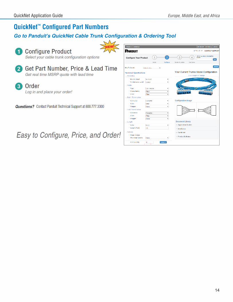
QuickNet™ Configured Part NumbersGo to Panduit’s QuickNet Cable Trunk Configuration & Ordering Tool
Visit our website or contact Panduit customer service for more information.
© Panduit Corp. 2015PN570 6/1515
QuickNet Application Guide Europe, Middle East, and Africa
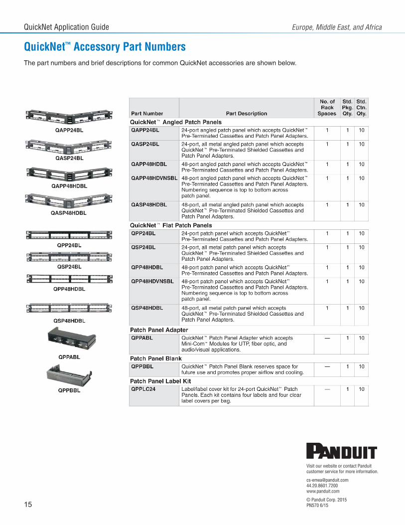
QuickNet™ Accessory Part NumbersThe part numbers and brief descriptions for common QuickNet accessories are shown below.