Embed Size (px)
Citation preview
Quiver XT Quick Intro Guide and New Feature
OutlineQuiver XT-QIG-v.1.2
3/7/16
This document describes the new feature set of the Quiver XT. It is intended for the user with some familiarity as to the basic operation of the Quiver Xcor.
2
Table of Contents Overview ....................................................................................................................................... 3 Operational modes ........................................................................................................................ 3 CPD Radar ...................................................................................................................................... 4
Zoom mode in Passive radar ........................................................................................................... 4 Active radar mode ........................................................................................................................... 5
NTC TDR ........................................................................................................................................ 6 Connecting to a line passive ............................................................................................................ 9 Connecting to an amplifier ............................................................................................................ 10 Using the TDR ................................................................................................................................ 11 Check Spectrum ............................................................................................................................ 11 Recommended TDR signal level .................................................................................................... 12 TDR run modes .............................................................................................................................. 12
Spectrum analyzer/Signal level meter modes .............................................................................. 13 Return spectrum analyzer mode ................................................................................................... 13 Forward SLM/Spectrum mode ...................................................................................................... 13 Examples of actual FWD spectrum signals .................................................................................... 15
QAM demodulator mode ............................................................................................................. 16
3
Overview Quiver XT is loaded with many new features and capabilities. These include: Network Traffic Compatible (NTC) TDR which uniquely enables accurate TDR
functionality on active plant. It is designed as a PNM field companion tool. Increased Xcor radar detection bandwidth – passive CPD detection is now
correlated over the entire return bandwidth, providing an order of magnitude increase in resolution.
Active CPD radar feature, which provides a means for CPD detection in the home and new construction certification for spans of cable without active QAM channels.
QAM demodulator and constellation. User friendly Signal Level Meter functions that automatically senses modulation
type and indicates level of analog, QAM, and OFDM signals. Increased bandwidth of return spectrum analyzer to 100 MHz.
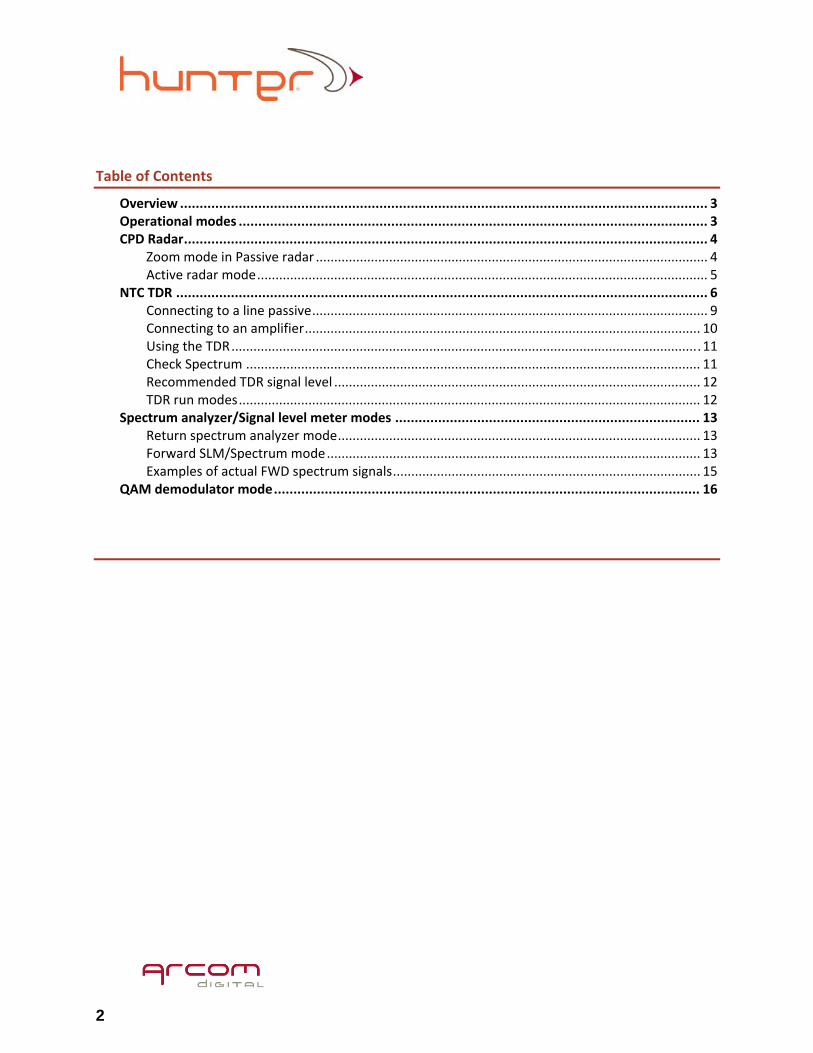
Operational modes Upon startup, all operational modes are indicated. Press the number for the desired
mode.
CPD radar mode includes both Passive and Active options
FWD and RTN spectrum analyzer is combined with the SLM presentation
4
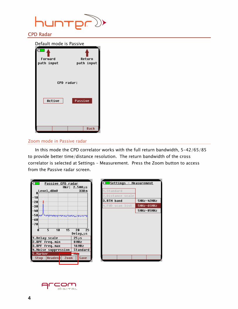
CPD Radar Default mode is Passive
Zoom mode in Passive radar
In this mode the CPD correlator works with the full return bandwidth, 5-42/65/85 to provide better time/distance resolution. The return bandwidth of the cross correlator is selected at Settings – Measurement. Press the Zoom button to access from the Passive radar screen.
5
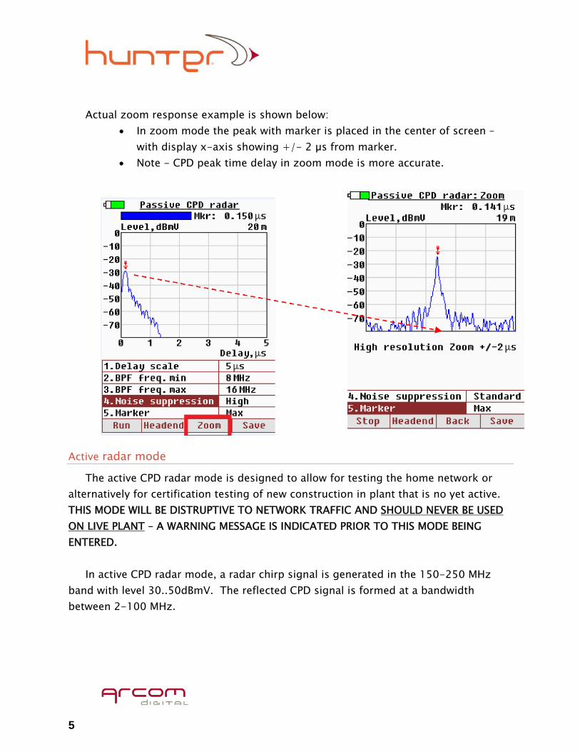
Actual zoom response example is shown below:
In zoom mode the peak with marker is placed in the center of screen – with display x-axis showing +/- 2 µs from marker.
Note - CPD peak time delay in zoom mode is more accurate.
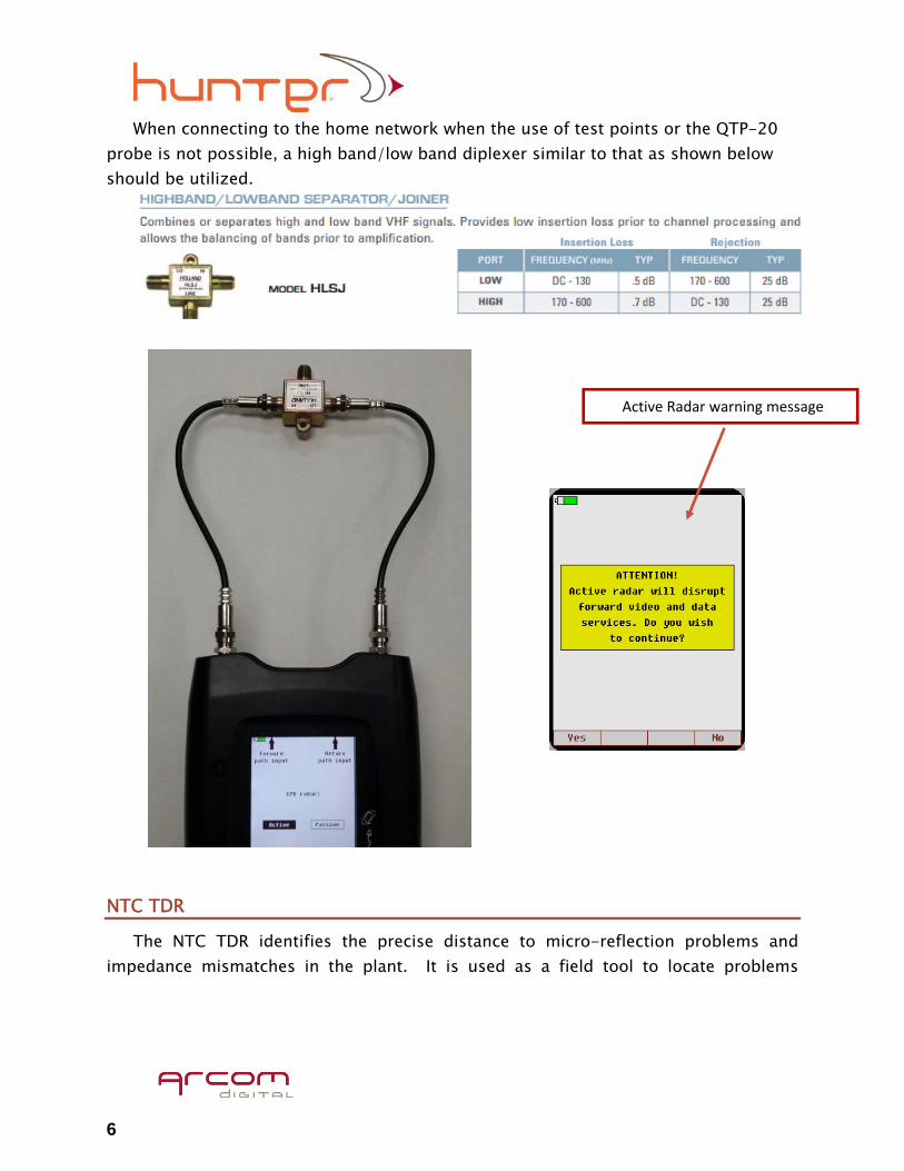
Active radar mode The active CPD radar mode is designed to allow for testing the home network or
alternatively for certification testing of new construction in plant that is no yet active. THIS MODE WILL BE DISTRUPTIVE TO NETWORK TRAFFIC AND SHOULD NEVER BE USED ON LIVE PLANT – A WARNING MESSAGE IS INDICATED PRIOR TO THIS MODE BEING ENTERED.
In active CPD radar mode, a radar chirp signal is generated in the 150-250 MHz
band with level 30..50dBmV. The reflected CPD signal is formed at a bandwidth between 2-100 MHz.
6
When connecting to the home network when the use of test points or the QTP-20 probe is not possible, a high band/low band diplexer similar to that as shown below should be utilized.
NTC TDR The NTC TDR identifies the precise distance to micro-reflection problems and
impedance mismatches in the plant. It is used as a field tool to locate problems
Active Radar warning message
7
identified from PNM initiatives. The NTC TDR is completely different from any other existing TDR. The NTC TDR calculation of the time distance and corresponding physical distance to the impedance mismatch is based on an autocorrelation process which utilizes very low level non-intrusive spread spectrum signals transmitted at return path frequencies in the forward. It is effective from the connection point to the next amplifier.
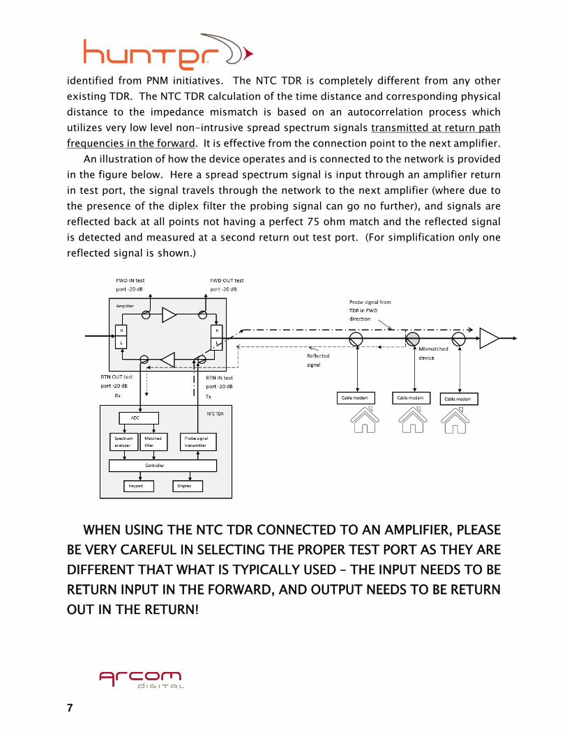
An illustration of how the device operates and is connected to the network is provided in the figure below. Here a spread spectrum signal is input through an amplifier return in test port, the signal travels through the network to the next amplifier (where due to the presence of the diplex filter the probing signal can go no further), and signals are reflected back at all points not having a perfect 75 ohm match and the reflected signal is detected and measured at a second return out test port. (For simplification only one reflected signal is shown.)
WHEN USING THE NTC TDR CONNECTED TO AN AMPLIFIER, PLEASE
BE VERY CAREFUL IN SELECTING THE PROPER TEST PORT AS THEY ARE DIFFERENT THAT WHAT IS TYPICALLY USED – THE INPUT NEEDS TO BE RETURN INPUT IN THE FORWARD, AND OUTPUT NEEDS TO BE RETURN OUT IN THE RETURN!
8
The NTC TDR output display is unique in that it provides a presentation of easily
understandable return loss across the measured span. This output format is significantly improved over that provided by status quo TDRs which just provide difficult to interpret impedance bumps indicating shorts or opens.
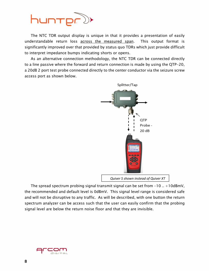
As an alternative connection methodology, the NTC TDR can be connected directly to a line passive where the forward and return connection is made by using the QTP-20, a 20dB 2 port test probe connected directly to the center conductor via the seizure screw access port as shown below.
The spread spectrum probing signal transmit signal can be set from -10 .. +10dBmV, the recommended and default level is 0dBmV. This signal level range is considered safe and will not be disruptive to any traffic. As will be described, with one button the return spectrum analyzer can be access such that the user can easily confirm that the probing signal level are below the return noise floor and that they are invisible.
Quiver S shown instead of Quiver XT
9
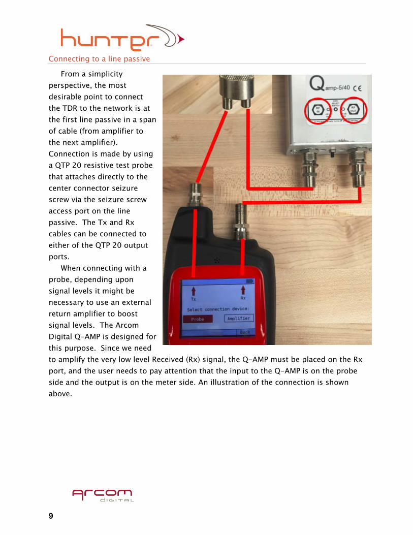
Connecting to a line passive
From a simplicity perspective, the most desirable point to connect the TDR to the network is at the first line passive in a span of cable (from amplifier to the next amplifier). Connection is made by using a QTP 20 resistive test probe that attaches directly to the center connector seizure screw via the seizure screw access port on the line passive. The Tx and Rx cables can be connected to either of the QTP 20 output ports.
When connecting with a probe, depending upon signal levels it might be necessary to use an external return amplifier to boost signal levels. The Arcom Digital Q-AMP is designed for this purpose. Since we need to amplify the very low level Received (Rx) signal, the Q-AMP must be placed on the Rx port, and the user needs to pay attention that the input to the Q-AMP is on the probe side and the output is on the meter side. An illustration of the connection is shown above.
10
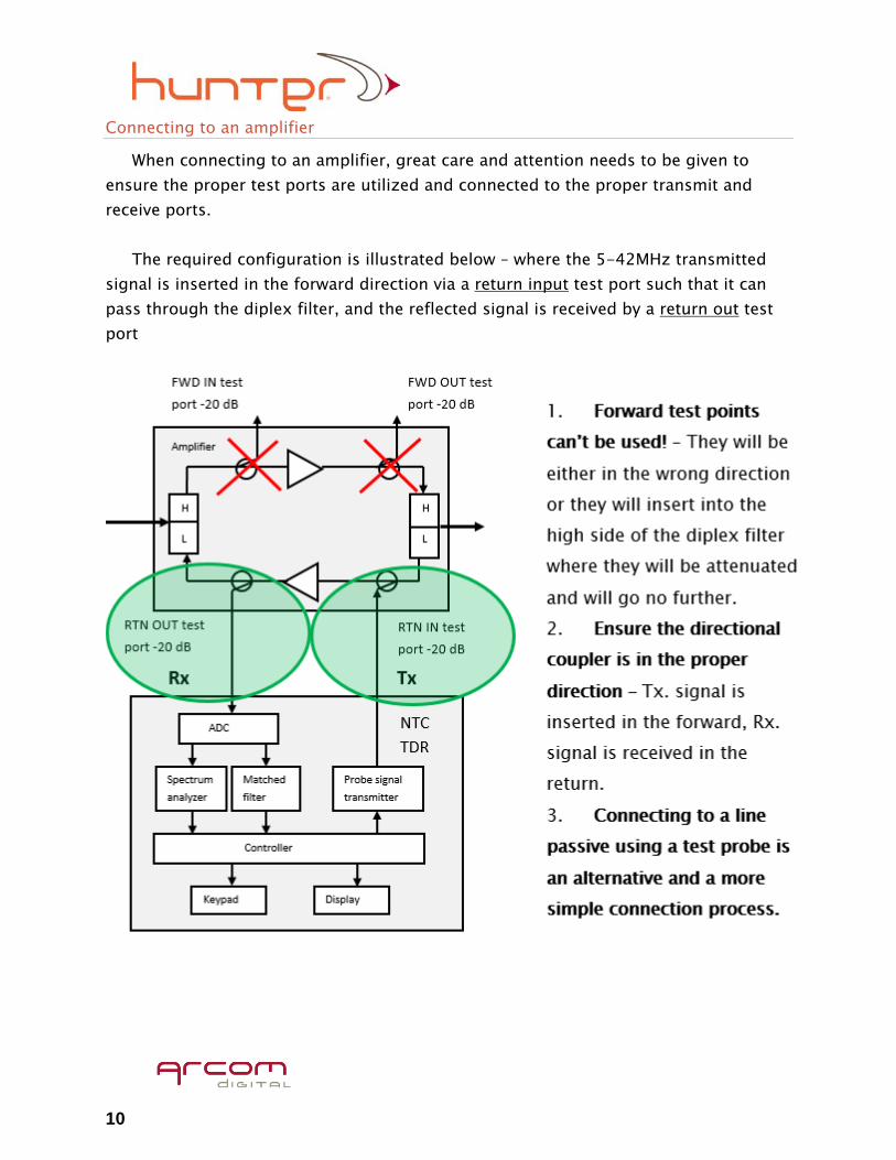
Connecting to an amplifier
When connecting to an amplifier, great care and attention needs to be given to ensure the proper test ports are utilized and connected to the proper transmit and receive ports.
The required configuration is illustrated below – where the 5-42MHz transmitted
signal is inserted in the forward direction via a return input test port such that it can pass through the diplex filter, and the reflected signal is received by a return out test port
11
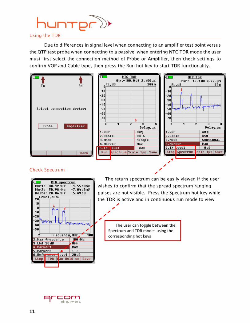
Using the TDR
Due to differences in signal level when connecting to an amplifier test point versus the QTP test probe when connecting to a passive, when entering NTC TDR mode the user must first select the connection method of Probe or Amplifier, then check settings to confirm VOP and Cable type, then press the Run hot key to start TDR functionality.
Check Spectrum
The return spectrum can be easily viewed if the user wishes to confirm that the spread spectrum ranging pulses are not visible. Press the Spectrum hot key while the TDR is active and in continuous run mode to view.
The user can toggle between the Spectrum and TDR modes using the corresponding hot keys
12
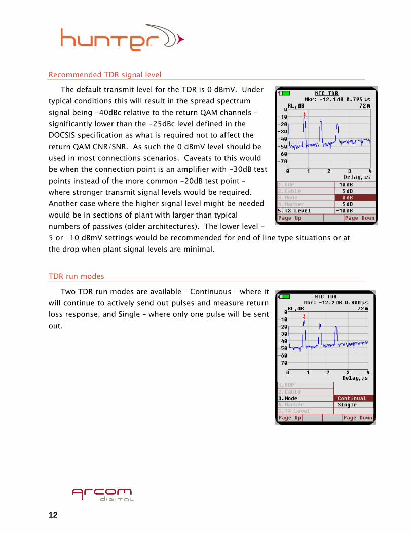
Recommended TDR signal level
The default transmit level for the TDR is 0 dBmV. Under typical conditions this will result in the spread spectrum signal being -40dBc relative to the return QAM channels – significantly lower than the -25dBc level defined in the DOCSIS specification as what is required not to affect the return QAM CNR/SNR. As such the 0 dBmV level should be used in most connections scenarios. Caveats to this would be when the connection point is an amplifier with -30dB test points instead of the more common -20dB test point – where stronger transmit signal levels would be required. Another case where the higher signal level might be needed would be in sections of plant with larger than typical numbers of passives (older architectures). The lower level -5 or -10 dBmV settings would be recommended for end of line type situations or at the drop when plant signal levels are minimal.
TDR run modes
Two TDR run modes are available – Continuous – where it will continue to actively send out pulses and measure return loss response, and Single – where only one pulse will be sent out.
13
Spectrum analyzer/Signal level meter modes
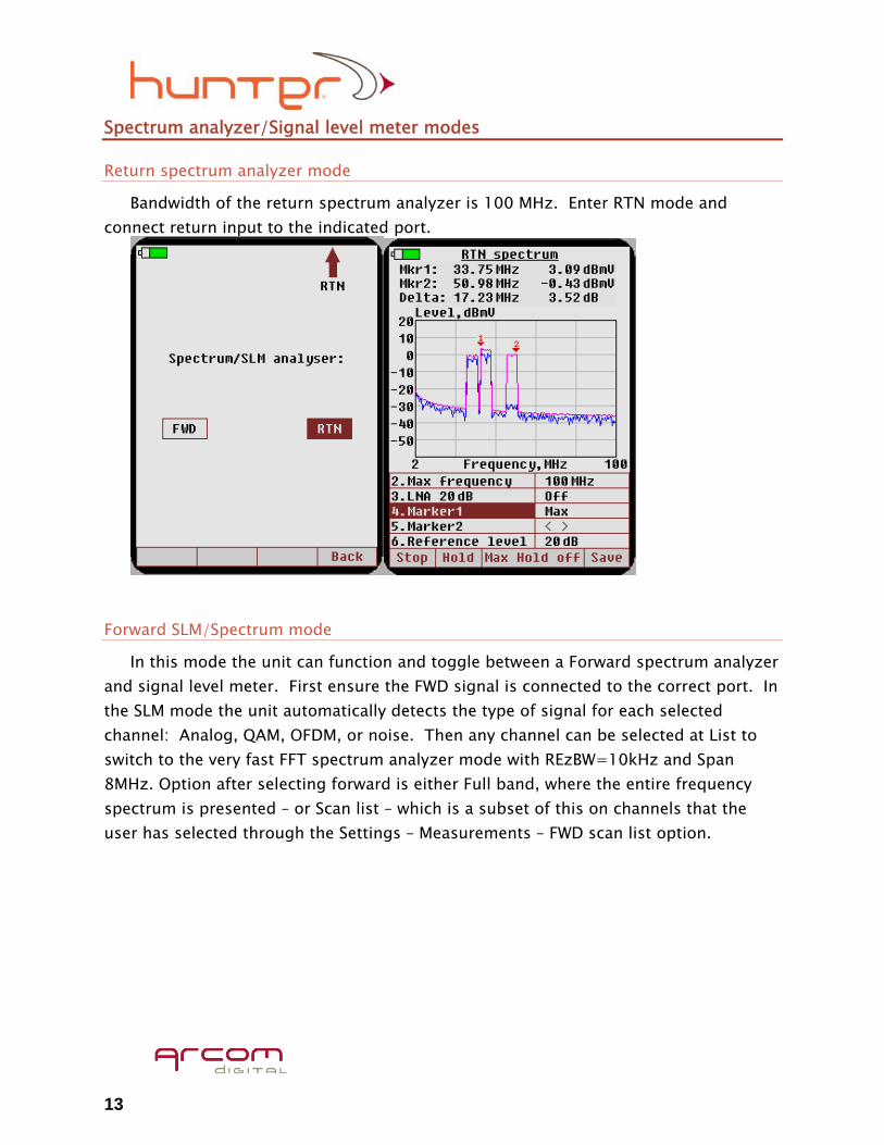
Return spectrum analyzer mode
Bandwidth of the return spectrum analyzer is 100 MHz. Enter RTN mode and connect return input to the indicated port.
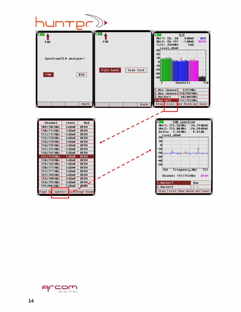
Forward SLM/Spectrum mode
In this mode the unit can function and toggle between a Forward spectrum analyzer and signal level meter. First ensure the FWD signal is connected to the correct port. In the SLM mode the unit automatically detects the type of signal for each selected channel: Analog, QAM, OFDM, or noise. Then any channel can be selected at List to switch to the very fast FFT spectrum analyzer mode with REzBW=10kHz and Span 8MHz. Option after selecting forward is either Full band, where the entire frequency spectrum is presented – or Scan list – which is a subset of this on channels that the user has selected through the Settings – Measurements – FWD scan list option.
14
15
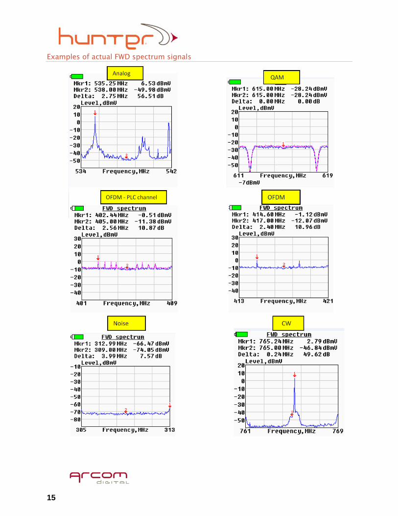
Examples of actual FWD spectrum signals
16
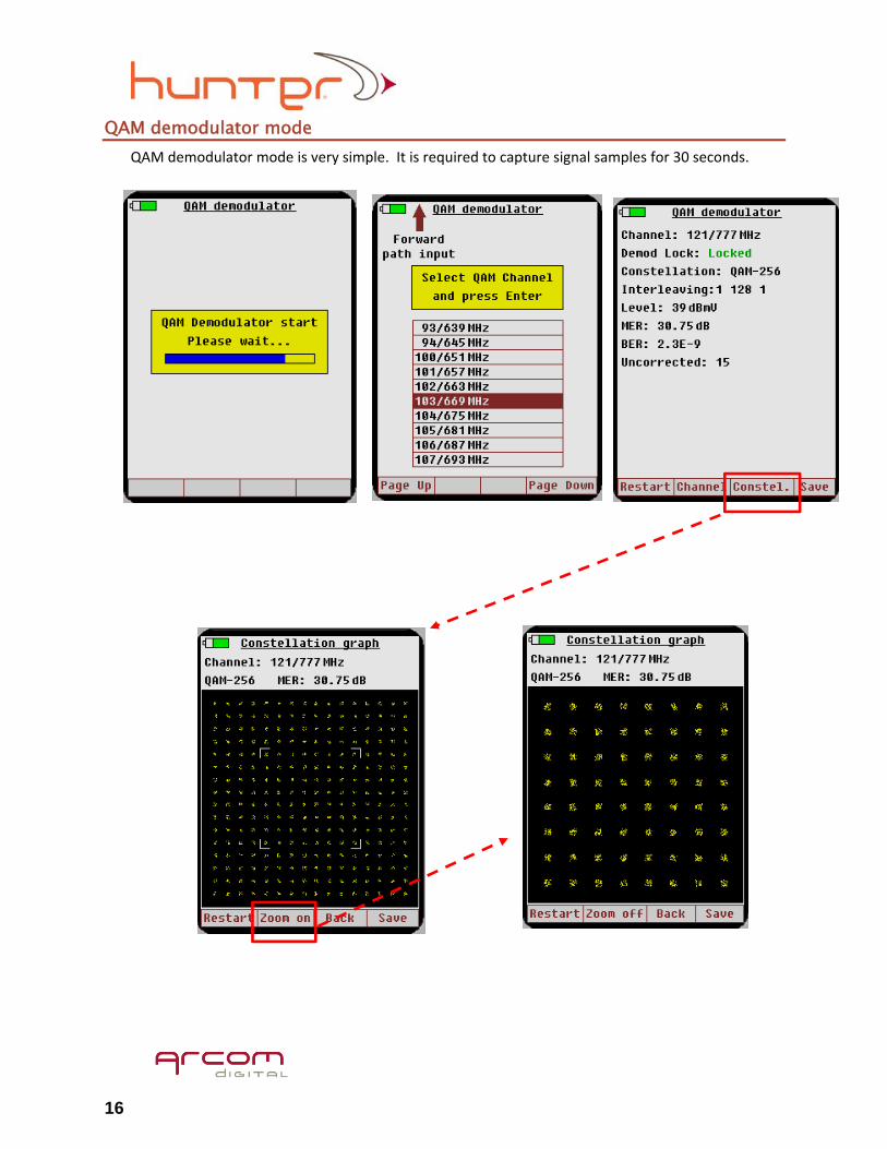
QAM demodulator mode QAM demodulator mode is very simple. It is required to capture signal samples for 30 seconds.


![A categorical action on quantized quiver varietiesA categorical action on quantized quiver varieties andthe author [BPW, 6.1-2]. Viewedcorrectly, these bimodules on the quiver varieties](https://img.pdfslide.net/doc/110x75/60816382864c6250c6675e0a/a-categorical-action-on-quantized-quiver-varieties-a-categorical-action-on-quantized.jpg)